WO2020054320A1 - 流体圧シリンダ - Google Patents
流体圧シリンダ Download PDFInfo
- Publication number
- WO2020054320A1 WO2020054320A1 PCT/JP2019/032233 JP2019032233W WO2020054320A1 WO 2020054320 A1 WO2020054320 A1 WO 2020054320A1 JP 2019032233 W JP2019032233 W JP 2019032233W WO 2020054320 A1 WO2020054320 A1 WO 2020054320A1
- Authority
- WO
- WIPO (PCT)
- Prior art keywords
- pressure chamber
- pressure
- piston
- chamber
- cylinder
- Prior art date
- Legal status (The legal status is an assumption and is not a legal conclusion. Google has not performed a legal analysis and makes no representation as to the accuracy of the status listed.)
- Ceased
Links
Images







Classifications
-
- F—MECHANICAL ENGINEERING; LIGHTING; HEATING; WEAPONS; BLASTING
- F15—FLUID-PRESSURE ACTUATORS; HYDRAULICS OR PNEUMATICS IN GENERAL
- F15B—SYSTEMS ACTING BY MEANS OF FLUIDS IN GENERAL; FLUID-PRESSURE ACTUATORS, e.g. SERVOMOTORS; DETAILS OF FLUID-PRESSURE SYSTEMS, NOT OTHERWISE PROVIDED FOR
- F15B15/00—Fluid-actuated devices for displacing a member from one position to another; Gearing associated therewith
- F15B15/08—Characterised by the construction of the motor unit
- F15B15/14—Characterised by the construction of the motor unit of the straight-cylinder type
Definitions
- the present invention relates to a fluid pressure cylinder.
- a booster piston is provided as a booster mechanism, and the thrust is increased by locking the booster piston to a piston rod during a stroke.
- a plurality of steel balls are disposed inside a coupling body accommodating chamber formed inside a booster piston, and when the booster piston advances by the action of high-pressure air, the steel balls are engaged with a piston rod.
- the booster piston is locked to the piston rod by being locked in the stop groove.
- an object of the present invention is to provide a fluid pressure cylinder capable of increasing the thrust in the latter half of a stroke with a simpler structure.
- One aspect of the present invention is a cylinder body provided with a working cylinder chamber and a booster cylinder chamber in order from the head side, and is disposed slidably in the working cylinder chamber in the axial direction, and the working cylinder chamber is connected to the head side.
- An operating piston that partitions the first pressure chamber into a second pressure chamber on the end side, a third pressure chamber disposed on the head side, and slidably disposed in the booster cylinder chamber in the axial direction.
- An intensifying piston partitioning into an end-side fourth pressure chamber, an opening formed at a predetermined distance from the end side of the working cylinder chamber, and an opening formed in the intensifying cylinder chamber;
- a communication passage for communicating the cylinder chamber with the third pressure chamber and a connection groove connected to the working piston and connected to the booster piston are formed, and an end is formed through the booster piston.
- a lock piston provided on the booster piston, and the lock piston is moved by the high-pressure air introduced from the first pressure chamber into the third pressure chamber via the communication passage.
- a lock mechanism for engaging the booster piston with the piston rod by engaging with a connection groove of the piston rod, wherein after the booster piston is connected to the piston rod, the operating piston and the booster piston have a high pressure.
- a fluid pressure cylinder for displacing the piston rod to an end side under the action of air.
- the lock mechanism is driven by the action of the high-pressure air introduced into the third pressure chamber from the first pressure chamber via the communication passage, and the booster piston is connected to the piston rod. . Therefore, the thrust of the piston rod in the latter half of the forward stroke can be increased with a simple device configuration without providing a port for controlling the lock mechanism.
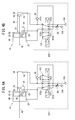
- FIG. 4A is a fluid circuit diagram of a hydraulic cylinder and a driving device thereof according to the first embodiment, showing a connection state of a switching valve at a first position
- FIG. 4B is a diagram of a switching valve at a second position of FIG. 4A.
- FIG. 4 is a fluid circuit diagram showing a connection state of FIG.
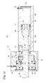
- FIG. 2 is a cross-sectional view showing an operation in a step of boosting a lock piston of the hydraulic cylinder of FIG. 1.
- FIG. 2 is a cross-sectional view illustrating an operation of a return process of the hydraulic cylinder in FIG.
- FIG. 2 is a cross-sectional view illustrating a state in which a working piston has returned to a stroke start end position in a return process of the hydraulic cylinder in FIG. 1. It is a top view of the fluid pressure cylinder concerning a 2nd embodiment.
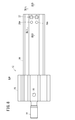
- 9A is a cross-sectional view along the line IXA-IXA of FIG. 8
- FIG. 9B is a cross-sectional view along the line IXB-IXB of FIG.
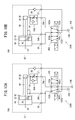
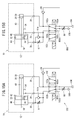
- FIG. 10A is a fluid circuit diagram of the hydraulic cylinder and its driving device of FIG. 8, showing a connection state of a switching valve at a first position
- FIG. 10B is a connection state of a switching valve of FIG. 10A at a second position
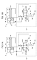
- FIG. FIG. 11A is a fluid circuit diagram of a fluid pressure cylinder and a driving device thereof according to a third embodiment, showing a connection state of a switching valve at a first position
- FIG. 11B is a diagram of a switching valve at a second position of FIG. 11A.
- FIG. 4 is a fluid circuit diagram showing a connection state of FIG.
- FIG. 11B is a cross-sectional view showing the operation of the return process of the hydraulic cylinder driven by the driving device of FIG.
- FIG. 14A is a fluid circuit diagram of the hydraulic cylinder and its driving device of FIG. 13, showing a connection state of a switching valve at a first position
- FIG. 14B is a connection state of a switching valve of FIG. 14A at a second position
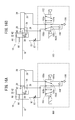
- FIG. 15A is a fluid circuit diagram of a fluid pressure cylinder and a driving device thereof according to a fifth embodiment, illustrating a connection state of a switching valve at a first position
- FIG. 15B is a diagram of a switching valve of FIG. 15A at a second position.
- FIG. 4 is a fluid circuit diagram showing a connection state of FIG. FIG.
- FIG. 16A is a fluid circuit diagram of a fluid pressure cylinder and a drive device thereof according to a sixth embodiment, showing a connection state of a switching valve at a first position
- FIG. 16B is a diagram of a switching valve of FIG. 16A at a second position
- FIG. 4 is a fluid circuit diagram showing a connection state of FIG.
- the hydraulic cylinder 10 includes a cylinder body 12 that extends in the axial direction.
- the cylinder body 12 is formed of, for example, a metal material such as an aluminum alloy, and may be, for example, a square shape.
- the cylinder body 12 includes a head-side main body portion 14 provided on the head side and an end-side main body portion 16 provided on the end side, and is fastened in the axial direction by a plurality of connecting rods or bolts 12c.
- a working cylinder chamber 14 b having a circular cross section is formed inside the head-side main body section 14, and a booster cylinder chamber 16 b having a circular cross section is formed inside the end-side main body section 16. ing.
- a head-side port 28 is formed near the head-side end of the head-side main body 14, and an operating-port exhaust port 29 is formed near the end-side end of the head-side main body 14. Are formed. Further, near the end on the end side of the end-side main body 16, a booster portion exhaust port 30 is provided.
- the hydraulic cylinder 10 supplies high-pressure air (working fluid) from the head-side port 28 and exhausts internal air from the operation part exhaust port 29 and the booster part exhaust port 30, so that the piston rod 18 Are projected.
- the head-side main body 14 generates a large stroke motion
- the end-side main body 16 is configured to generate an additional thrust in the latter half of the stroke.
- the high-pressure air refers to air having a pressure higher than the pressure (for example, the atmospheric pressure) of the atmosphere in which the fluid pressure cylinder 10 is installed.
- the head-side main body 14 of the cylinder body 12 includes a working cylinder chamber 14 b, a head-side port 28, a head cover 14 c, a flow path 34 b forming a part of a communication passage 34, An exhaust port 29 and a piston unit 21 are provided.
- the working cylinder chamber 14b is a hollow portion having a circular cross section formed inside the side wall 14a, and extends in the axial direction.
- a head cover 14c is attached to one end of the working cylinder chamber 14b. The head cover 14c seals the head side of the working cylinder chamber 14b.
- a head-side port 28 is formed near the head cover 14c so as to penetrate the side wall 14a, and communicates with the working cylinder chamber 14b.
- the head-side port 28 is formed at a position where it can communicate with the first pressure chamber 38 on the head side of the working piston 20 even when the working piston 20 described later moves to the head-end position on the head side.
- the flow path 34b is formed to extend in the axial direction inside the side wall 14a on the end side of the head-side main body 14.
- the flow path 34b extends in the axial direction by a predetermined length from the end side end of the head-side main body 14, bends inward at a substantially right angle, and communicates with the working cylinder chamber 14b at the opening 34a.
- the opening 34a is arranged at a position separated by a predetermined distance from the end side end of the working cylinder chamber 14b.
- the opening 34a is configured to be able to communicate with the first pressure chamber 38 on the head side of the working piston 20 when the working piston 20 moves to the end side.
- the operating section exhaust port 29 is provided on the top, side, or bottom of the head-side main body 14, penetrates the side wall 14a, and communicates with the operating cylinder chamber 14b.
- the operating unit exhaust port 29 is provided on a side surface of the head-side main body 14.
- the operating part exhaust port 29 is formed at a position where it can communicate with the second pressure chamber 40 on the end side of the working piston 20 even when the working piston 20 moves to the end position on the end side.
- a piston unit 21 having an operating piston 20 and a piston rod 18 connected to the operating piston 20 is disposed inside the operating cylinder chamber 14b.
- the piston unit 21 is accommodated in the working cylinder chamber 14b so as to be slidable in the axial direction, and the inside of the working cylinder chamber 14b is airtightly connected to the first pressure chamber 38 on the head side and the second pressure chamber 40 on the end side. Partitioning.
- the working piston 20 includes a circular piston body 50 protruding radially outward from the piston rod 18, a wear ring 52 attached to the outer periphery of the piston body 50, and a magnet 56 attached to the outer periphery of the piston body 50. And a circular ring-shaped packing 54 attached to the outer peripheral portion of the piston main body 50, and a sealing portion 58 extending to the end side of the piston main body 50.
- a wear ring arrangement groove 52a On the outer peripheral surface of the piston main body 50, a wear ring arrangement groove 52a, a packing mounting groove 54a, and a magnet arrangement groove 56a are provided.
- the wear ring arrangement groove 52a is provided near the base end of the piston main body 50.
- the packing mounting groove 54a is disposed adjacent to the end of the wear ring mounting groove 52a, and the magnet mounting groove 56a is further disposed on the end side of the packing mounting groove 54a.
- the wear ring arrangement groove 52a, the packing attachment groove 54a, and the magnet arrangement groove 56a are all formed in a circular ring shape extending over the entire circumference in the circumferential direction.
- a cylindrical sealing portion 58 formed around the piston rod 18 is formed.
- the sealing portion 58 has an outer diameter substantially the same as the inner diameter of the communication portion 16d, which will be described later, and is formed to be freely inserted into and removed from the communication portion 16d. When the sealing portion 58 is inserted into the communication portion 16d, it seals the communication portion 16d.
- the piston body 50 is made of, for example, a metal material such as carbon steel, stainless steel, or an aluminum alloy, or a hard resin.
- the packing 54 is a ring-shaped seal member (for example, an O-ring) made of an elastic material such as a rubber material or an elastomer material.
- the packing 54 is slidably in contact with the inner peripheral surface of the working cylinder chamber 14b.
- the packing 54 seals the gap between the working piston 20 and the inner peripheral surface of the working cylinder chamber 14b, and hermetically partitions the first pressure chamber 38 and the second pressure chamber 40 of the working cylinder chamber 14b.
- the wear ring 52 is made of, for example, a synthetic resin material having low friction and abrasion resistance, such as tetrafluoroethylene (PTFE), or a metal material (for example, bearing steel).
- the magnet 56 is made of, for example, a link-shaped ferrite magnet or a rare earth magnet. The magnet 56 may be divided in the circumferential direction.
- the piston rod 18 is connected to the working piston 20 at a connecting portion 18c provided on the head side.
- the piston rod 18 extends to the end side through the end side main body 16 and the booster piston 22.
- a connection groove 18 a for connecting to the booster piston 22 is formed on the outer peripheral portion of the piston rod 18.
- the connection groove 18a is formed at a position separated from the connection portion of the piston rod 18 with the working piston 20 by a predetermined distance toward the end side, and is formed annularly over the entire circumference of the piston rod 18 in the circumferential direction.
- An annular packing 18b for preventing air from leaking along the piston rod 18 is mounted on an outer peripheral portion of the piston rod 18 between the connection groove 18a and the working piston 20.
- the packing 18 b is disposed in a groove formed in an annular shape over the entire circumference of the piston rod 18.
- the end of the head-side main body 14 on the end side is a flat end face 14d, and the working cylinder chamber 14b and the flow path 34b are open on the end face 14d.
- the end surface 14d is in contact with the head-side end surface 16i of the end-side main body 16.
- a circular ring-shaped packing 16h is disposed between the end surface 14d of the head-side main body 14 and the end surface 16i of the end-side main body 16.
- the packing 16 h hermetically seals the connection between the head-side main body 14 and the end-side main body 16.
- the end-side main body 16 includes a booster cylinder chamber 16 b, a booster piston 22, a booster exhaust port 30, a lock mechanism 35, and a flow path 34 c forming a part of the communication passage 34.
- the booster cylinder chamber 16b is a hollow section having a circular cross section, and is formed to penetrate the end-side main body section 16 in the axial direction. An end portion on the end side of the booster cylinder chamber 16b is sealed by a rod cover 16c.
- the booster cylinder chamber 16b has, in order from the head, a connecting portion 16d, a piston housing portion 16e, a piston sliding portion 16f, and a rod cover mounting portion 16g.
- the connecting portion 16d is formed to have a larger inner diameter than the piston rod 18, and is configured to form a space in which air can move between the connecting portion 16d and the piston rod 18.
- a packing mounting groove 16j1 formed over the entire circumference in the circumferential direction is provided on the inner peripheral surface of the connecting portion 16d, and a circular ring-shaped packing 16j is mounted in the packing mounting groove 16j1. .
- the packing 16j tightly contacts the outer peripheral surface of the sealing portion 58 of the working piston 20 to hermetically seal the working cylinder chamber 14b and the booster cylinder chamber 16b.
- the piston housing portion 16e has an inner diameter slightly larger than the diameter of the small diameter portion 60b of the booster piston 22, which will be described later, and is configured to accommodate the small diameter portion 60b.
- the piston sliding portion 16f is a hollow portion formed with substantially the same inner diameter as the sliding portion 60c of the booster piston 22, and has a smooth inner peripheral surface such that the sliding portion 60c can slide in the axial direction. .
- the rod cover mounting portion 16g is provided on the end side of the booster cylinder chamber 16b, and is formed according to the outer diameter of the rod cover 16c so that the rod cover 16c is mounted.
- the locking groove 67a is a groove formed for mounting a retaining clip 67 for retaining the rod cover 16c, and is formed in a ring shape over the entire circumference in the circumferential direction.
- the retaining clip 67 is an annular plate member with a part cut off in the circumferential direction, and the retaining clip 67 inserted into the locking groove 67a engages with the locking groove 67a by elastic restoring force.
- the retaining clip 67 contacts the end side of the rod cover 16c to prevent the rod cover 16c from falling off.
- the rod cover 16c is formed in a substantially columnar shape, and has an annular groove 76a formed in an outer peripheral portion thereof.
- a circular ring-shaped packing 76 is mounted in the annular groove 76a.
- the packing 76 is disposed between the rod cover 16c and the rod cover mounting portion 16g, and hermetically seals the booster cylinder chamber 16b.
- a rod hole 71 for inserting the piston rod 18 is formed extending in the axial direction.
- the rod hole 71 is provided with a rod packing 69 for preventing air from leaking along the piston rod 18.
- the rod packing 69 is mounted in an annular groove 69 a formed on the inner peripheral surface of the rod hole 71.
- the booster piston 22 has a cylindrical booster piston main body 60. At the center of the booster piston main body 60, an insertion hole 60a formed of a circular cavity is formed.
- the insertion hole 60a has a slightly larger inner diameter than the piston rod 18, and is configured to be able to insert the piston rod 18 in the axial direction.
- a packing mounting groove 68a is formed on the inner peripheral surface of the insertion hole 60a, and a packing 68 for preventing air from leaking along the piston rod 18 is mounted in the packing mounting groove 68a.
- the booster piston main body 60 has a sliding portion 60c formed with a relatively large outer diameter and a small diameter formed on the head side of the sliding portion 60c with a smaller outer diameter than the sliding portion 60c. And a portion 60b.
- a wear ring disposing groove 62a and a packing mounting groove 64a are provided on the outer peripheral surface of the sliding portion 60c, and the wear ring 62 and the packing 64 are mounted on each of them.
- Each of the wear ring disposing groove 62a and the packing mounting groove 64a is formed in a circular ring shape extending over the entire circumference in the circumferential direction.
- the packing 64 is slidably in contact with the inner peripheral surface of the piston sliding portion 16f of the booster cylinder chamber 16b.
- the packing 64 seals between the booster piston 22 and the inner peripheral surface of the booster cylinder chamber 16b, and the booster cylinder chamber 16b is airtightly partitioned into the third pressure chamber 42 and the fourth pressure chamber 44.
- the packing 64 causes the sliding resistance of the booster piston 22, the packing 64 may be configured such that the sliding resistance is larger than the sliding resistance of the working piston 20.
- an annular mounting groove 66a is formed in the end face 60c1 on the end side of the sliding portion 60c.
- One end of the position holding means 66 is inserted into the mounting groove 66a.
- the other end of the position holding means 66 is inserted into a mounting groove 66b formed on the rod cover 16c side.
- the position holding means 66 is made of, for example, an elastic member such as a coil spring, and urges the booster piston 22 toward the head, and until the booster piston 22 is locked to the piston rod 18, the booster piston 22 starts the stroke on the head side. It is configured to remain in the position.
- the small diameter portion 60b is formed in a cylindrical shape having an outer diameter smaller than that of the sliding portion 60c, and is accommodated in the piston accommodating portion 16e of the booster cylinder chamber 16b.
- the small diameter portion 60b is provided with a lock mechanism portion 35 that engages with the connection groove 18a (see FIG. 2) of the piston rod 18 and connects the booster piston 22 to the piston rod 18.
- the lock mechanism 35 has a through hole 63 penetrating in the radial direction.
- the through hole 63 has a piston sliding portion 63a formed radially outward and a lock pin insertion portion 63b formed radially inside.
- the piston sliding portion 63a is open at the outer peripheral portion of the booster piston 22.
- a communication groove 63h extending in the axial direction is formed in the outer peripheral portion of the booster piston 22 so as to communicate with the piston sliding portion 63a.
- the piston sliding portion 63a and the third pressure chamber 42 communicate with each other via the communication groove 63h.
- an air passage 61 extending in the axial direction is formed on a side portion near the lower end of the piston sliding portion 63a.
- the ventilation passage 61 extends in the axial direction of the booster piston main body 60, and communicates with the fourth pressure chamber 44 at an opening 61b that communicates with the piston sliding portion 63a. That is, the lower end side of the piston sliding portion 63 a communicates with the fourth pressure chamber 44 via the ventilation path 61.
- a lock pin insertion portion 63b is formed at an inner end (lower end in the figure) of the piston sliding portion 63a.
- the lock pin insertion portion 63b is a circular cavity formed with an inner diameter smaller than the piston sliding portion 63a, and an inner peripheral end of the piston sliding portion 63a is open to the insertion hole 60a.
- the lock piston 36 is provided in the through hole 63.
- the lock piston 36 has a pressure-receiving portion 36a having an outer diameter substantially equal to the inner diameter of the piston sliding portion 63a, and an outer diameter smaller than the pressure-receiving portion 36a, and has substantially the same outer diameter as the inner diameter of the lock pin insertion portion 63b.
- the pressure receiving portion 36a is arranged so as to be slidable in the direction in which the piston slide portion 63a extends. As shown in FIG.
- the pressure receiving portion 36 a has a packing 36 e mounted on an outer peripheral portion thereof, and communicates the piston sliding portion 63 a with a first region 63 c that communicates with the third pressure chamber 42 and with the fourth pressure chamber 44. Partition into the second region 63d.
- the pressure receiving portion 36a generates a thrust for displacing the lock piston 36 toward the piston rod 18 by receiving the pressure of the third pressure chamber 42 on the pressure receiving surface 36c outside the pressure receiving portion 36a.
- the lock pin 36b extends from the pressure receiving portion 36a toward the center of the booster piston body 60, and has an outer diameter substantially equal to the inner diameter of the lock pin insertion portion 63b.
- the lock pin 36b is inserted to be insertable into the lock pin insertion portion 63b.
- a packing 63g is mounted on an inner peripheral portion of the lock pin insertion portion 63b. The packing 63g prevents air leakage along the lock pin 36b by being in close contact with the lock pin 36b.
- the lock pin 36b is formed to have an outer diameter substantially equal to or smaller than the axial width of the connecting groove 18a so as to be able to engage with the connecting groove 18a of the piston rod 18.
- a stopper 37 is mounted outside the lock piston 36.
- the stopper 37 is a clip-shaped member formed of an elastic material that is formed in an annular shape and partially cut out in the circumferential direction.
- the stopper 37 is engaged with a stopper mounting groove 37a formed on the inner peripheral surface of the piston sliding portion 63a, and regulates the outward movement of the lock piston 36 in the radial direction.
- An urging member 36g for urging the lock piston 36 radially outward is provided in a gap between the pressure receiving portion 36a of the lock piston 36 and the piston sliding portion 63a.
- the end-side main body 16 is provided with a flow path 34 c communicating with the flow path 34 b of the head-side main body 14.
- the flow path 34c extends in the axial direction in the end-side main body 16, and the end on the end side communicates with the head-side end of the booster cylinder chamber 16b at the opening 34e.
- the position of the opening 34e is not limited to the end of the booster cylinder chamber 16b on the head side, and is provided at a portion that becomes the third pressure chamber 42 when the booster piston 22 is located closest to the head. It should just be. That is, the communication path 34 having the flow path 34b and the flow path 34c is configured to communicate the working cylinder chamber 14b and the third pressure chamber 42.
- the hydraulic cylinder 10 is configured as described above, and the driving device 120 will be described below.
- the driving device 120 of the hydraulic cylinder 10 includes a check valve 86, a high-pressure air supply source 104, a throttle valve 88, an exhaust port 106, a switching valve 102, and predetermined piping. It becomes.
- the driving device 120 supplies high-pressure air to the first pressure chamber 38 of the working cylinder chamber 14b in the operation step, and also transfers a part of the high-pressure air accumulated in the first pressure chamber 38 to the second pressure chamber in the return step. It is configured to supply the pressure toward the pressure chamber 40 and the fourth pressure chamber 44.
- the switching valve 102 is, for example, a five-port two-position valve having first to fifth ports 102a to 102e, and is switchable between a first position and a second position.
- the switching valve 102 is switched between a first position and a second position by a pilot pressure from a high-pressure air supply source 104 or an electromagnetic valve.
- the first port 102 a of the switching valve 102 is connected to the first pressure chamber 38 by a pipe, and is connected to the upstream side of the check valve 86.
- the second port 102b is connected to the second pressure chamber 40 and the fourth pressure chamber 44 by piping.
- the third port 102c is connected to a downstream side of the check valve 86 by a pipe.
- the fourth port 102d is connected to the exhaust port 106 via a throttle valve 88 by a pipe.
- the fifth port 102e is connected to the high-pressure air supply source 104 by a pipe.
- the switching valve 102 When the switching valve 102 is at the first position, the first port 102a and the fifth port 102e are connected, and the second port 102b and the fourth port 102d are connected. Further, as shown in FIG. 4B, when the switching valve 102 is at the second position, the first port 102a and the fourth port 102d are connected, and the second port 102b and the third port 102c are connected.
- the check valve 86 When the check valve 86 is at the second position of the switching valve 102, the check valve 86 allows the flow of air from the first pressure chamber 38 to the second pressure chamber 40 and the fourth pressure chamber 44, and allows the second pressure chamber 40 and the The flow of air from the fourth pressure chamber 44 to the first pressure chamber 38 is blocked.
- the throttle valve 88 is provided to limit the amount of air exhausted from the exhaust port 106, and is configured as a variable throttle valve having a variable passage area so that the exhaust flow rate can be adjusted.
- an air tank is provided in the middle of a pipe connecting the second port 102b and the second pressure chamber 40 and the fourth pressure chamber 44 to accumulate air supplied to the second pressure chamber 40 and the fourth pressure chamber 44. You may do so.
- the air tank By providing the air tank, a sufficient amount of air can be accumulated to fill the second pressure chamber 40 at the time of the return operation, and the return operation can be reliably performed.
- the capacity of the air tank may be set to, for example, about half of the maximum capacity of the first pressure chamber 38. When the volume of the pipe can be sufficiently secured, the air tank is not required.
- the fluid pressure cylinder 10 and the drive device 120 are configured as described above, and the operation and operation will be described below.
- the operation process of the hydraulic cylinder 10 is performed with the switching valve 102 of the driving device 120 as the first position.
- the high-pressure air from the high-pressure air supply source 104 is supplied to the head-side port 28 via the first port 102a of the switching valve 102.
- the check valve 86 is connected to the third port 102c, and high-pressure air does not flow to the check valve 86 side.
- the operating section exhaust port 29 and the booster section exhaust port 30 are connected to the second port 102b of the switching valve 102, and are connected to the exhaust port 106 via the throttle valve 88.
- the high-pressure air supplied to the head-side port 28 flows into the first pressure chamber 38 of the working cylinder chamber 14b.
- the second pressure chamber 40 adjacent to the working piston 20 communicates with the third pressure chamber 42 via the communication portion 16d. Further, the second pressure chamber 40 communicates with the exhaust port 106 through the operating section exhaust port 29 and the pipe.
- a driving force corresponding to the pressure difference between the pressure in the first pressure chamber 38 and the pressure (atmospheric pressure) in the second pressure chamber 40 acts on the working piston 20, and the working piston 20 is pushed toward the stroke end.
- the piston rod 18 is displaced integrally with the working piston 20 and moves toward the stroke end.
- the air in the second pressure chamber 40 is exhausted from the exhaust port 106.
- the third pressure chamber 42 adjacent to the booster piston 22 communicates with the exhaust port 106 (see FIG. 4A) via the second pressure chamber 40, and the fourth pressure chamber 44 communicates with the exhaust port 106 via a pipe. Therefore, there is no pressure difference between the third pressure chamber 42 and the fourth pressure chamber 44 adjacent to the booster piston 22, and the booster piston 22 is held at the head-side end of the booster cylinder chamber 16b by the position holding means 66. You.
- the boosting step is started when the packing 54 of the working piston 20 moves to the end side from the opening 34 a of the communication passage 34.
- the packing 54 of the working piston 20 moves to the end side of the opening 34 a through the opening 34 a of the communication passage 34.
- the sealing portion 58 of the working piston 20 is inserted into the communication portion 16d, and the communication portion 16d is sealed.
- the second pressure chamber 40 and the third pressure chamber 42 are airtightly partitioned, and the first pressure chamber 38 and the third pressure chamber 42 communicate with each other via the communication passage 34.
- the high-pressure air in the first pressure chamber 38 flows into the third pressure chamber 42 through the communication path 34, and the pressure in the third pressure chamber 42 increases. Then, due to the pressure difference between the third pressure chamber 42 and the fourth pressure chamber 44, the lock piston 36 of the lock mechanism 35 is pushed out toward the piston rod 18, and the tip of the lock piston 36 is connected to the piston rod 18. It engages with the groove 18a. That is, the booster piston 22 is connected to the piston rod 18.
- the high-pressure air flowing into the third pressure chamber 42 generates a thrust toward the end side of the booster piston 22. Since the diameter of the boosting piston 22 is larger than the diameter of the working piston 20, the boosting piston 22 generates a larger thrust than the working piston 20. Since the thrust of the boost piston 22 is added to the thrust of the working piston 20, the thrust of the piston rod 18 increases in the latter half of the stroke.
- the boosting step is performed until the working piston 20 and the boosting piston 22 reach the stroke end. Since the stroke length (also referred to as a stroke range) of the boosting step is shorter than the stroke range of the operating step, the amount of high-pressure air required to drive the booster piston 22 in the boosting step is equal to the amount of air consumed in the operating step. Less than the quantity.
- the switching valve 102 of the driving device 120 is set to the second position.
- the first pressure chamber 38 is connected to a throttle valve 88 via a first port 102 a and a fourth port 102 d of the switching valve 102, and high-pressure air in the first pressure chamber 38 is exhausted from an exhaust port 106 via the throttle valve 88. Is done. A part of the high-pressure air in the first pressure chamber 38 is supplied to the second pressure chamber 40 and the fourth pressure chamber 44 via the check valve 86.
- the internal pressure of the third pressure chamber 42 decreases as the exhaust of the first pressure chamber 38 proceeds.
- the pressure difference between the third pressure chamber 42 and the fourth pressure chamber 44 decreases, and the lock piston 36 of the lock mechanism 35 retreats into the through hole 63 under the action of the urging member 36g.
- the connection state between the booster piston 22 and the piston rod 18 is released.
- the third pressure chamber 42 and the second pressure chamber 40 communicate with each other when the sealing portion 58 of the working piston 20 is removed by passing through the packing 16j of the communication portion 16d.
- the high-pressure air flowing into the second pressure chamber 40 and the fourth pressure chamber 44 is supplied from a part of the high-pressure air discharged from the head-side port 28. Therefore, it is not necessary to supply high-pressure air from the high-pressure air supply source 104 in the return step.
- the fluid pressure cylinder 10 according to the present embodiment has the following effects.
- the lock mechanism 35 is formed so as to penetrate in the radial direction of the booster piston 22, and has an outer side communicating with the third pressure chamber 42 and an inner side opening into an insertion hole 60 a for inserting the piston rod 18.
- the second region 63d and the fourth pressure chamber 44 communicate with the hole 63, the lock piston 36 inserted into the through hole 63 and dividing the through hole 63 into an outer first region 63c and an inner second region 63d.
- the lock piston 36 of the lock mechanism 35 protrudes inward of the booster piston 22 due to a pressure difference between the third pressure chamber 42 and the fourth pressure chamber 44 and has a connection groove for the piston rod 18. 18a.
- the booster piston 22 and the piston rod 18 can be connected with a simple device configuration.
- the communication passage 34 connects the first pressure chamber 38 and the third pressure chamber 42 to each other, and the high pressure is applied to the third pressure chamber 42. It is configured to introduce air. This makes it possible to operate the lock mechanism 35 and connect the booster piston 22 to the piston rod 18 with a simple device configuration.
- the booster piston 22 In the hydraulic cylinder 10, the booster piston 22 generates a thrust by the pressure of the high-pressure air introduced into the third pressure chamber 42 through the communication passage 34. That is, an additional thrust can be generated in the booster piston 22 at the same time as the connection between the booster piston 22 and the piston rod 18.
- the through-hole 63 may be provided with an urging member 36g for urging the lock piston 36 radially outward. Thereby, in the return step, the retracting operation of the lock piston 36 can be reliably performed.
- the cylinder body 12 may have the operating section exhaust port 29 communicating with the second pressure chamber 40.
- the air inside the second pressure chamber 40 can be exhausted.
- a connecting portion 16d formed to have a larger diameter than the piston rod 18 and communicating the second pressure chamber 40 of the working cylinder chamber 14b and the third pressure chamber 42 of the booster cylinder chamber 16b; And a sealing portion 58 which is inserted into the communication portion 16d near the stroke end of the piston rod 18 to prevent communication between the second pressure chamber 40 and the third pressure chamber 42. May be. Thereby, in the boosting step, the high-pressure air is introduced into the third pressure chamber 42, and the booster piston 22 can be reliably operated.
- high-pressure air may be supplied from the first pressure chamber 38 to the third pressure chamber 42 via the communication passage 34. Good. Thereby, the outflow of the high-pressure air through the third pressure chamber 42 can be prevented, and the usage amount of the high-pressure air can be suppressed.
- the diameter of the booster piston 22 may be larger than the diameter of the working piston 20. Thereby, the thrust in the latter half of the stroke can be further increased.
- the stroke length of the booster piston 22 may be shorter than the stroke length of the working piston.
- the amount of high-pressure air consumed in the boosting step can be reduced.
- the pressure at which the booster piston 22 starts sliding in the axial direction may be greater than the pressure at which the working piston 20 starts sliding in the axial direction.
- the movement of the booster piston 22 can be delayed until the lock mechanism 35 operates and the booster piston 22 is connected to the piston rod 18.
- the reliability of the operation of the hydraulic cylinder 10 can be improved.
- a position holding unit 66 for urging the booster piston 22 toward the head may be provided in the booster cylinder chamber 16b.
- the position of the booster piston 22 is maintained at the head side until the booster piston 22 is connected to the piston rod 18, and the thrust from the booster piston 22 can be added to the piston rod 18 before the stroke end. .
- the fluid pressure cylinder 10 further includes a driving device 120 having a switching valve 102, a high-pressure air supply source 104, a check valve 86, and an exhaust port 106.
- the first pressure chamber 38 communicates with the high-pressure air supply source 104
- the second pressure chamber 40 and the fourth pressure chamber 44 communicate with the exhaust port 106.
- the second pressure chamber 40 and the fourth pressure chamber 44 may be connected to the first pressure chamber 38 via the check valve 86 while communicating with the exhaust port 106.
- a part of the high-pressure air stored in the first pressure chamber 38 can be supplied to the second pressure chamber 40 and the fourth pressure chamber 44.
- the supply of the high-pressure air from the high-pressure air supply source 104 is not required in the return step, so that the consumption of the high-pressure air can be suppressed.
- a throttle valve 88 may be provided between the first pressure chamber 38 and the exhaust port 106 and downstream of the check valve 86.
- the hydraulic cylinder 10A of the present embodiment is different from the hydraulic cylinder 10 of FIG. 1 in that a check valve 86 and a throttle valve 88A shown in FIGS. 4A and 4B are incorporated in the cylinder body 12.
- a check valve 86 and a throttle valve 88A shown in FIGS. 4A and 4B are incorporated in the cylinder body 12.
- the hydraulic cylinder 10A of the present embodiment will be described with reference to FIGS. 8 to 10.
- the same configuration as the hydraulic cylinder 10 described with reference to FIGS. are denoted by the same reference numerals, and a detailed description thereof will be omitted.
- the operating portion exhaust port 29A, the head side port 28A, and the exhaust introduction port 27 are arranged concentrated on the head side of the cylinder body 12.
- the operating section exhaust port 29 ⁇ / b> A communicates with the second pressure chamber 40 at an end on the end side of the operating cylinder chamber 14 b via a flow path 82 formed inside the cylinder body 12. .
- An exhaust introduction port 27 is provided on the head side of the operating section exhaust port 29A.
- a check valve 86 is provided inside the exhaust introduction port 27.
- the exhaust introduction port 27 communicates with the first pressure chamber 38 via a check valve 86.
- the exhaust introduction port 27 is connected to a third port 102c of the switching valve 102 through a pipe.
- the passage 82 between the operating section exhaust port 29A and the exhaust introducing port 27 is sealed by a steel ball, and the operating section exhaust port 29A and the exhaust introducing port 27 are isolated.
- the head-side port 28A communicates with the first pressure chamber 38 via a throttle valve 88A, as shown in FIG. 9B. That is, high pressure air is supplied to the first pressure chamber 38 via the throttle valve 88A.
- a check valve (not shown) that allows high-pressure air to flow from the head-side port 28A toward the first pressure chamber 38 is built in the throttle valve 88A in parallel. Since the supply can be performed, the delivery speed of the piston rod 18 does not decrease.
- the fluid pressure cylinder 10A of the present embodiment is driven by a driving device 120A shown in FIGS. 10A and 10B.
- the driving device 120A has a switching valve 102, a high-pressure air supply source 104, and an exhaust port 106.
- the head side port 28A is connected to the first port 102a of the switching valve 102 via a pipe.
- the operating section exhaust port 29A and the booster section exhaust port 30 are connected to the second port 102b via a pipe.
- the exhaust port 27 is connected to the third port 102c via a pipe.
- An exhaust port 106 is connected to the fourth port 102d.
- the high pressure air supply source 104 is connected to the fifth port 102e.
- the first port 102a and the fifth port 102e are connected, and the high-pressure air supply source 104 and the head-side port 28A are connected. Further, the second port 102b and the fourth port 102d are connected, and the operating unit exhaust port 29A and the booster unit exhaust port 30 communicate with the exhaust port 106.
- the first port 102a and the fourth port 102d are connected, and the head-side port 28A communicates with the exhaust port 106. Further, the second port 102b and the third port 102c are connected, and the exhaust introduction port 27 communicates with the operating section exhaust port 29A and the booster section exhaust port 30.
- the hydraulic cylinder 10A of the present embodiment configured as described above operates in the same manner as the hydraulic cylinder 10 of the first embodiment.
- the hydraulic cylinder 10A has a head-side port 28A, an operating unit exhaust port 29A, and an exhaust introduction port 27 concentrated on the head side of the cylinder body 12, thereby providing piping for installing the hydraulic cylinder 10A. Connection work becomes easy.
- the throttle valve 88A and the check valve 86 are built in the cylinder body 12, so that the configuration of the driving device 120A can be simplified.
- the hydraulic cylinder 10 As shown in FIG. 11A, the hydraulic cylinder 10 according to the present embodiment is driven by a driving device 130.
- the drive device 130 is configured to supply a small amount of high-pressure air to the hydraulic cylinder 10 in a return process in order to ensure the return operation of the hydraulic cylinder 10.
- the same components as those of the fluid pressure cylinder 10 and the driving device 120 of the first embodiment are denoted by the same reference numerals, and detailed description thereof is omitted.
- the drive device 130 includes a check valve 86, a throttle valve 88, a switching valve 102, a high-pressure air supply source 104, an exhaust port 106, a second check valve 112, and a throttle valve 114.
- the driving device 130 is configured to supply high-pressure air to the first pressure chamber 38 of the operation cylinder chamber 14b in an operation process. Further, as shown in FIG. 11B, the driving device 130 supplies a part of the high-pressure air accumulated in the first pressure chamber 38 toward the second pressure chamber 40, and It is configured to supply high-pressure air from a high-pressure air supply source 104 to 44.
- the switching valve 102 is, for example, a 5-port 2-position valve, has first to fifth ports 102a to 102e, and switches between a first position (see FIG. 11A) and a second position (see FIG. 11B). It is possible. As shown in FIGS. 11A and 11B, the first port 102a is connected to the first pressure chamber 38 by a pipe. The second port 102b is connected to the fourth pressure chamber 44 and the downstream side of the second check valve 112 by piping. The third port 102c is connected to the exhaust port 106 by a pipe. The fourth port 102d is connected to a high-pressure air supply source 104 by a pipe. The fifth port 102e is connected to the exhaust port 106 via a throttle valve 88 via a pipe, and to the second pressure chamber 40 via a check valve 86.
- the switching valve 102 when the switching valve 102 is at the first position, the first port 102a and the fourth port 102d are connected, and the second port 102b and the third port 102c are connected.
- the switching valve 102 when the switching valve 102 is at the second position, the first port 102a and the fifth port 102e are connected, and the second port 102b and the fourth port 102d are connected.
- the switching valve 102 is switched between a first position and a second position by a pilot pressure from a high-pressure air supply source 104 or an electromagnetic valve.
- the check valve 86 allows the flow of air from the first pressure chamber 38 to the second pressure chamber 40, and goes from the second pressure chamber 40 to the first pressure chamber 38. Block air flow.
- the throttle valve 114 is disposed between the second port 102b and the fourth pressure chamber 44 in order to reliably operate the lock mechanism 35 of the booster piston 22.
- the fourth pressure chamber 44 is open to the atmosphere via the exhaust port 106. Further, an air tank is provided in the middle of the pipe connecting the check valve 86 and the second pressure chamber 40 so that the air supplied from the first pressure chamber 38 to the second pressure chamber 40 is accumulated in the return step. Is also good.
- the hydraulic cylinder 10 and the driving device 130 of the present embodiment are configured as described above, and the operation and operation will be described below.
- the operation step and the boosting step of the hydraulic cylinder 10 are performed with the switching valve 102 of the driving device 130 as the first position.
- the high-pressure air from the high-pressure air supply source 104 is supplied to the first pressure chamber 38 via the first port 102a of the switching valve 102.
- the air inside the second pressure chamber 40 is exhausted from the exhaust port 106 via the second check valve 112, the second port 102b and the third port 102c of the switching valve 102.
- the air inside the fourth pressure chamber 44 is exhausted from the exhaust port 106 via the second port 102b and the third port 102c.
- the return process of the hydraulic cylinder 10 is performed by setting the switching valve 102 of the driving device 130 to the second position.
- the high-pressure air from the high-pressure air supply source 104 is supplied to the fourth pressure chamber 44 via the second port 102b of the switching valve 102.
- the high-pressure air from the high-pressure air supply source 104 is blocked by the second check valve 112 and is not supplied to the second pressure chamber 40.
- the first pressure chamber 38 is connected to the throttle valve 88 via the first port 102 a and the fifth port 102 e of the switching valve 102, and the high-pressure air in the first pressure chamber 38 passes through the exhaust port 106 via the throttle valve 88. It is exhausted from. A part of the high-pressure air in the first pressure chamber 38 is supplied to the second pressure chamber 40 via the check valve 86.
- the exhaust of the first pressure chamber 38 proceeds, and the working piston 20 moves in the return direction under the action of the air pressure flowing into the second pressure chamber 40. Further, the booster piston 22 moves to the head side by the internal pressure of the fourth pressure chamber 44 and the urging force of the position holding means 66. Through the above operation, the booster piston 22 and the working piston 20 return to the starting position of the stroke, and the return process is completed.
- the air flowing into the second pressure chamber 40 is supplied from the first pressure chamber 38, so that the supply of high-pressure air is not required when the working piston 20 returns. Further, the booster piston 22 is returned by the high-pressure air from the high-pressure air supply source 104. However, since the capacity of the fourth pressure chamber 44 is smaller than the capacity of the second pressure chamber 40, a small amount of high-pressure air is required for returning the booster piston 22.
- the hydraulic cylinder 10 and the driving device 130 according to the present embodiment have the following effects.
- the fluid pressure cylinder 10 may include a driving device 130 having a switching valve 102, a high-pressure air supply source 104, a check valve 86, a second check valve 112, and an exhaust port 106.
- the driving device 130 connects the first pressure chamber 38 to the high-pressure air supply source 104 at the first position of the switching valve 102 and connects the second pressure chamber 40 to the exhaust port 106 through the second check valve 112.
- the fourth pressure chamber 44 may be communicated with the exhaust port 106.
- the first pressure chamber 38 is communicated with the exhaust port 106
- the second pressure chamber 40 is communicated with the first pressure chamber 38 via the check valve 86.
- the pressure chamber 44 may communicate with the high-pressure air supply source 104.
- a throttle valve 88 may be provided between the check valve 86 and the exhaust port 106.
- the driving device 130 since the high-pressure air from the high-pressure air supply source 104 can be supplied to the fourth pressure chamber 44 in the return step, the connection between the piston rod 18 and the booster piston 22 by the lock mechanism 35 is performed. The release of the state and the return operation of the booster piston 22 can be reliably performed. As a result, the return operation can be stabilized.
- the fluid pressure cylinder 10B includes position holding means 66A for urging the booster piston 22 toward the head.
- the configuration other than the position holding means 66A is the same as that of the fluid pressure cylinder 10 shown in FIG.
- the position holding means 66A is made of an elastic member such as a coil spring, and its urging force is higher than that of the position holding means 66 in FIG. It is preferable that the urging force of the position holding means 66A is set to a magnitude at least capable of overcoming the sliding resistance of the booster piston 22 and displacing the booster piston 22 toward the head.
- the hydraulic cylinder 10B can be driven by the driving device 140.
- This driving device 140 is different from the driving device 120 shown in FIGS. 4A and 4B in that the intensifier exhaust port 30 is open to the atmosphere and is not connected to the second port 102b of the switching valve 102. The other points are the same as those of the driving device 120.
- the fluid pressure cylinder 10B can be driven by the driving device 120.
- the hydraulic cylinder 10B of the present embodiment configured as described above operates in the same manner as the hydraulic cylinder 10 up to the operation step.
- the third pressure chamber 42 and the first pressure chamber 38 communicate with each other via the communication passage 34, and when the internal pressure of the third pressure chamber 42 increases, a force pressing the booster piston 22 toward the end acts. .
- the lock piston 36 operates to connect the booster piston 22 to the piston rod 18.
- the fluid pressure cylinder 10B can reliably apply the thrust of the booster piston 22 to the piston rod 18.
- the booster piston 22 has a larger diameter than the working piston 20, and thus starts sliding at a lower pressure. Therefore, depending on conditions, there is a possibility that the booster piston 22 may move before the lock mechanism 35 operates.
- the booster piston 22 is urged by the position holding means 66A. This makes the pressure at which the booster piston 22 starts sliding equal to or higher than the sliding start pressure of the working piston 20. As a result, it is possible to prevent incompatibility in which the booster piston 22 is displaced toward the end side before being connected to the piston rod 18.
- the urging force of the position holding means 66A displaces the booster piston 22 to the head-side end when the internal pressure of the first pressure chamber 38 and the third pressure chamber 42 decreases. Let it. Therefore, the booster piston 22 can be returned to the stroke start position without introducing exhaust air or high-pressure air from the booster section exhaust port 30.
- the lock piston 36 returns to the initial position under the action of the urging member 36g.
- the fluid pressure cylinder 10B of the present embodiment configured as described above has the following effects.
- the internal pressure of the third pressure chamber 42 when the booster piston 22 starts to move in the axial direction is equal to or higher than the internal pressure of the first pressure chamber 38 when the working piston 20 starts to move in the axial direction.
- the fluid pressure cylinder 10B even when the booster unit exhaust port 30 is opened to the atmosphere, the fluid pressure cylinder 10B operates, so that it is not necessary to connect a pipe to the booster unit exhaust port 30, and the apparatus configuration is simplified.
- the fluid pressure cylinder 10 (see FIG. 2) is driven by the driving device 150.
- the basic configuration of the driving device 150 is the same as that of the driving device 120 shown in FIG. 4A, except that a second throttle valve 87 and a check valve 87a are provided in a pipe between the booster unit exhaust port 30 and the switching valve 102. Is different.
- the check valve 87a can flow air only in a direction from the second port 102b of the switching valve 102 to the booster unit exhaust port 30.
- the check valve 87a is connected in parallel with the second throttle valve 87.
- the second throttle valve 87 is configured such that the speed of discharging air from the fourth pressure chamber 44 can be adjusted.
- the operation of the hydraulic cylinder 10 in the operation process is basically the same as that of the first embodiment described with reference to FIGS. 2 and 5. However, this embodiment is different from the first embodiment in that the exhaust air introduced into the fourth pressure chamber 44 in the return step remains due to the operation of the second throttle valve 87.
- the process is switched to the step of increasing the force.
- the exhaust air of the fourth pressure chamber 44 remains without being exhausted, and the pressure of the fourth pressure chamber 44 is higher than the atmospheric pressure (back pressure). Maintained high. Therefore, at the time of switching to the boosting step, the boosting piston 22 is biased toward the head under the action of the internal pressure of the fourth pressure chamber 44.
- the volume of the fourth pressure chamber 44 decreases with the stroke of the booster piston 22 toward the end side, and the air inside the fourth pressure chamber 44 is exhausted near the stroke end.
- a thrust corresponding to the pressure difference between the fourth pressure chamber 44, the atmospheric pressure (back pressure), and the internal pressure of the third pressure chamber 42 acts on the booster piston 22, and a large thrust is applied. Can be generated.
- the fluid pressure cylinder 10 includes a driving device 150 having a second throttle valve 87 between the fourth pressure chamber 44 and the exhaust port 106 for regulating the speed of discharging air from the fourth pressure chamber 44. ing. That is, in the hydraulic cylinder 10, the booster piston 22 is urged toward the head by the internal pressure of the air remaining in the fourth pressure chamber 44. Thus, after switching to the boosting step, the displacement of the booster piston 22 can be delayed until the booster piston 22 is connected to the piston rod 18. As a result, the booster piston 22 and the piston rod 18 can be reliably connected, and the operation reliability can be improved.
- the fluid pressure cylinder 10 and the driving device 150 of the present embodiment when the booster piston 22 strokes to the end side, the air in the fourth pressure chamber 44 that hinders the generation of the thrust of the booster piston 22 escapes. . As a result, the thrust generated at the end of the stroke of the boosting step becomes larger than when the biasing force is increased by the position holding unit 66A.
- the fluid pressure cylinder 10 (see FIG. 2) is driven by the driving device 160.
- the driving device 160 is different from the driving device 120 of FIG. 4A in that it does not have a path for introducing a part of the exhaust air exhausted from the first pressure chamber 38 to the second pressure chamber 40 during the return stroke. different.
- the driving device 160 includes a second throttle valve 87, a switching valve 102, a high-pressure air supply source 104, and an exhaust port 106.
- the switching valve 102 is a five-port two-position valve and includes a first port 102a to a fifth port 102e.
- the first port 102a is connected to the first pressure chamber 38 of the hydraulic cylinder 10 by a pipe.
- the second port 102b is connected to the second pressure chamber 40 of the fluid pressure cylinder 10 and the second throttle valve 87 by a pipe.
- the third port 102c and the fifth port 102e are connected to the exhaust port 106 by piping.
- the fourth port 102d is connected to a high-pressure air supply source 104 by a pipe.
- the switching valve 102 when the switching valve 102 is at the first position, the first port 102a is connected to the fourth port 102d. Further, the second port 102b is connected to the third port 102c. That is, the first pressure chamber 38 of the fluid pressure cylinder 10 communicates with the high-pressure air supply source 104 via the piping and the switching valve 102. Further, the second pressure chamber 40 and the fourth pressure chamber 44 of the fluid pressure cylinder 10 communicate with the exhaust port 106.
- the switching valve 102 when the switching valve 102 is at the second position, the first port 102a is connected to the fifth port 102e, and the second port 102b is connected to the fourth port 102d. That is, the first pressure chamber 38 of the fluid pressure cylinder 10 communicates with the exhaust port 106 via the piping and the switching valve 102. Further, the second pressure chamber 40 and the fourth pressure chamber 44 of the fluid pressure cylinder 10 communicate with a high-pressure air supply source 104 via a pipe and a switching valve 102.
- the return step is performed with the switching valve 102 of the driving device 160 as the second position as shown in FIG. 16B.
- the first pressure chamber 38 is connected to the exhaust port 106, and all the high-pressure air in the first pressure chamber 38 is exhausted from the exhaust port 106.
- high-pressure air from the high-pressure air supply source 104 is supplied to the fourth pressure chamber 44 via the second throttle valve 87.
- the lock of the piston rod 18 by the lock mechanism 35 of the booster piston 22 is released, and the booster piston 22 returns to the head side.
- high-pressure air from the high-pressure air supply source 104 is introduced into the second pressure chamber 40, and the working piston 20 is displaced toward the head side, and the working piston 20 returns to the stroke start position.
- the second pressure chamber 40 and the fourth pressure chamber 44 are communicated with the high-pressure air supply source 104, so that the return operation can be reliably performed. Can be.
- the present invention is not limited to this.
- Some or all of the members constituting the driving devices 120, 120A, 130, 140, 150, and 160 may be built in the cylinder body 12.
Landscapes
- Engineering & Computer Science (AREA)
- Physics & Mathematics (AREA)
- Fluid Mechanics (AREA)
- Mechanical Engineering (AREA)
- General Engineering & Computer Science (AREA)
- Actuator (AREA)
Abstract
作動ピストン(20)及びピストンロッド(18)のストロークの後半に、増力ピストン(22)をピストンロッド(18)に連結させて推力を増加させる流体圧シリンダ(10)において、増力ピストン(22)に径方向に延在し外側が第3圧力室(42)に連通した貫通孔(63)を設け、その貫通孔(63)に第3圧力室(42)の内圧の増加によってピストンロッド(18)側に突出してピストンロッド(18)の連結溝(18a)に係合するロックピストン(36)を設け、増力ピストン(22)の作動と同時に増力ピストン(22)をピストンロッド(18)に連結させる。
Description
本発明は、流体圧シリンダに関する。
クランプ装置やロック装置等の作業機械において、通常、作業工程の前半にあまり大きな駆動力を必要とせず、作業工程の後半に大きな駆動力を必要とする場合がある。このため、これらの作業機械に使用される流体圧シリンダとして、増力機構によりピストンロッドの前進ストローク後半の推力を増大させるようにした増力機構付きの流体圧シリンダが提案されている。
例えば、特開2018-17269号公報の流体圧シリンダでは、増力機構として、増力用ピストンを設け、ストロークの途中で、ピストンロッドに増力ピストンをロックさせることで推力を増加させる。
この流体圧シリンダでは、増力ピストンの内部に形成された連結体収容室の内部に複数の鋼球を配設し、高圧エアの作用で増力ピストンが前進するときに、鋼球をピストンロッドの係止溝に係止させることで、増力ピストンをピストンロッドにロックさせる。
しかし、上記の流体圧シリンダにおいて、鋼球を適切なタイミングで、ピストンロッドに係止させるために、制御用のポートを追加する等の工夫が必要となり、構造が複雑化してしまい、製造コストが高くなるとともに、動作の信頼性が低下するといった問題がある。
そこで、本発明は、より簡素な構造でストローク後半の推力を増大させることができる流体圧シリンダを提供することを目的とする。
本発明の一観点は、ヘッド側から順に作動シリンダ室と増力シリンダ室とが設けられたシリンダボディと、前記作動シリンダ室に軸方向に摺動可能に配設され、前記作動シリンダ室をヘッド側の第1圧力室とエンド側の第2圧力室とに仕切る作動ピストンと、前記増力シリンダ室に軸方向に摺動可能に配設され、前記増力シリンダ室をヘッド側の第3圧力室と、エンド側の第4圧力室とに仕切る増力ピストンと、前記作動シリンダ室のエンド側から所定距離離間した位置に形成された開口と、前記増力シリンダ室に形成された開口とを有し、前記作動シリンダ室と前記第3圧力室とを連通させる連通路と、前記作動ピストンと連結されるとともに、前記増力ピストンと連結するための連結溝が形成され、前記増力ピストンを貫通してエンド側に延在するピストンロッドと、前記増力ピストンに設けられたロックピストンを有し、前記第1圧力室から前記連通路を介して前記第3圧力室に導入された高圧エアによって前記ロックピストンを前記ピストンロッドの連結溝に係合させて前記増力ピストンを前記ピストンロッドに連結させるロック機構部と、を備え、前記増力ピストンが前記ピストンロッドに連結された後、前記作動ピストン及び前記増力ピストンが高圧エアの作用下に前記ピストンロッドをエンド側に変位させる、流体圧シリンダにある。
上記観点の流体圧シリンダによれば、第1圧力室から連通路を介して第3圧力室に導入された高圧エアの作用により、ロック機構部が駆動されて増力ピストンがピストンロッドに連結される。このため、ロック機構部の制御用のポートを設けることなく、簡素な装置構成により、前進ストローク後半のピストンロッドの推力を増大させることができる。
以下、本発明の好適な実施形態を挙げ、添付の図面を参照して詳細に説明する。なお、図面の寸法比率は、説明の都合上、誇張されて実際の比率とは異なる場合がある。また、本明細書において、ストロークの終端に向かう方向を「エンド方向」又は「エンド側」とよび、そのストロークの始端の方向を「ヘッド方向」又は「ヘッド側」と呼ぶ。また、以下の説明においては、作動流体としてエアを用いる例を示すが、以下の実施形態はこれに限定されるものではなく、エア以外の気体を用いることもできる。
(第1実施形態)
本実施形態に係る流体圧シリンダ10は、図1に示すように、軸方向に長く延びたシリンダボディ12を備えている。シリンダボディ12は、例えば、アルミニウム合金等の金属材料によって形成され、例えば、角型のものとすることができる。シリンダボディ12は、ヘッド側に設けられたヘッド側本体部14とエンド側に設けられたエンド側本体部16とを備え、複数の連結ロッド又はボルト12cにより軸方向に締結されている。
本実施形態に係る流体圧シリンダ10は、図1に示すように、軸方向に長く延びたシリンダボディ12を備えている。シリンダボディ12は、例えば、アルミニウム合金等の金属材料によって形成され、例えば、角型のものとすることができる。シリンダボディ12は、ヘッド側に設けられたヘッド側本体部14とエンド側に設けられたエンド側本体部16とを備え、複数の連結ロッド又はボルト12cにより軸方向に締結されている。
図2に示すように、ヘッド側本体部14の内部には、断面が円形の作動シリンダ室14bが形成され、エンド側本体部16の内部には、断面が円形の増力シリンダ室16bが形成されている。
図1に示すように、ヘッド側本体部14のヘッド側の端部付近には、ヘッド側ポート28が形成され、ヘッド側本体部14のエンド側の端部付近には、作動部排気ポート29が形成されている。また、エンド側本体部16のエンド側の端部付近には、増力部排気ポート30が設けられている。
流体圧シリンダ10は、作動工程において、ヘッド側ポート28から高圧エア(作動流体)を供給し、作動部排気ポート29及び増力部排気ポート30から内部のエアの排気を行うことにより、ピストンロッド18を突出させるように構成されている。その際に、ヘッド側本体部14は、大きなストローク動作を生み出し、エンド側本体部16はストローク後半において追加の推力を発生させるように構成されている。なお、高圧エアとは、流体圧シリンダ10が設置される雰囲気の圧力(例えば、大気圧)よりも高い圧力のエアをいうものとする。
図2に示すように、シリンダボディ12のヘッド側本体部14は、作動シリンダ室14bと、ヘッド側ポート28と、ヘッドカバー14cと、連通路34の一部を構成する流路34bと、作動部排気ポート29と、ピストンユニット21とを備える。作動シリンダ室14bは、側壁14aの内方に形成された断面が円形の中空部であり、軸方向に延在している。作動シリンダ室14bの一端には、ヘッドカバー14cが装着されている。ヘッドカバー14cは、作動シリンダ室14bのヘッド側を封じている。
ヘッドカバー14cの近傍には、ヘッド側ポート28が側壁14aを貫通するように形成され、作動シリンダ室14bと連通している。ヘッド側ポート28は、後述する作動ピストン20がヘッド側の始端位置に移動した場合であっても、作動ピストン20のヘッド側の第1圧力室38に連通可能な位置に形成されている。
流路34bは、ヘッド側本体部14のエンド側の側壁14aの内部に軸方向に延びて形成されている。流路34bは、ヘッド側本体部14のエンド側端部から所定の長さだけ軸方向に延び、内方に略直角に屈曲して開口部34aにおいて、作動シリンダ室14bに連通している。開口部34aは、作動シリンダ室14bのエンド側端部から所定距離離間した位置に配置されている。開口部34aは、作動ピストン20がエンド側に移動した際に、作動ピストン20のヘッド側の第1圧力室38と連通可能に構成されている。
作動部排気ポート29は、ヘッド側本体部14の上面、側面又は底面に設けられ、側壁14aを貫通して作動シリンダ室14bに連通している。なお、図示の例では、作動部排気ポート29はヘッド側本体部14の側面に設けられている。作動部排気ポート29は、作動ピストン20がエンド側の終端位置に移動した場合であっても、作動ピストン20のエンド側の第2圧力室40と連通可能な位置に形成されている。
作動シリンダ室14bの内部には、作動ピストン20と、作動ピストン20に連結されたピストンロッド18と、を備えたピストンユニット21が配設されている。ピストンユニット21は、作動シリンダ室14b内を軸方向に摺動可能に収容され、作動シリンダ室14bの内部を、ヘッド側の第1圧力室38とエンド側の第2圧力室40とに気密に仕切っている。
作動ピストン20は、ピストンロッド18から径方向外方に突出した円形のピストン本体50と、ピストン本体50の外周部に装着されたウエアリング52と、ピストン本体50の外周部に装着されたマグネット56と、ピストン本体50の外周部に装着された円形リング状のパッキン54と、ピストン本体50のエンド側に延在する封止部58とを有する。
ピストン本体50の外周面には、ウエアリング配置溝52aと、パッキン装着溝54aと、マグネット配置溝56aとが設けられている。ウエアリング配置溝52aは、ピストン本体50の基端付近に設けられている。パッキン装着溝54aは、ウエアリング配置溝52aのエンド側に隣接して配置され、マグネット配置溝56aは、パッキン装着溝54aのさらにエンド側に配置されている。ウエアリング配置溝52a、パッキン装着溝54a及びマグネット配置溝56aは、いずれも周方向の全周に亘って延在する円形リング状に形成されている。
ピストン本体50のエンド側には、ピストンロッド18の周囲に形成された円筒状の封止部58が形成されている。封止部58は、後述する、連絡部16dの内径と略同じ外径に形成されており、連絡部16d内に挿脱自在に形成されている。封止部58は、連絡部16dに挿入されると、連絡部16dを封止する。
ピストン本体50は、例えば、炭素鋼、ステンレス鋼、アルミニウム合金等の金属材料や、硬質樹脂等により形成されてなる。パッキン54は、ゴム材やエラストマー材等の弾性材料からなるリング状のシール部材(例えば、Oリング)である。パッキン54は、作動シリンダ室14bの内周面に摺動可能に接触している。パッキン54により、作動ピストン20と作動シリンダ室14bの内周面との間がシールされ、作動シリンダ室14bの第1圧力室38と第2圧力室40が気密に仕切られる。
ウエアリング52は、例えば、四フッ化エチレン(PTFE)のような低摩擦性と耐摩耗性を備えた合成樹脂材料や、金属材料(例えば、軸受鋼)等よりなる。マグネット56は、例えば、リンク状に形成されたフェライト磁石又は希土類磁石等よりなる。マグネット56は、周方向に分割されたものを用いてもよい。
ピストンロッド18は、ヘッド側に設けられた連結部18cにおいて、作動ピストン20と連結されている。ピストンロッド18は、エンド側本体部16及び増力ピストン22を貫通してエンド側に延在している。ピストンロッド18の外周部には、増力ピストン22と連結するための連結溝18aが形成されている。連結溝18aは、ピストンロッド18の作動ピストン20との連結部分からエンド側に所定距離だけ離間した位置に形成されており、ピストンロッド18の周方向の全周に亘って環状に形成されている。連結溝18aと作動ピストン20との間のピストンロッド18の外周部には、ピストンロッド18に沿ったエアの漏洩を防ぐための環状のパッキン18bが装着されている。パッキン18bは、ピストンロッド18の全周に亘って環状に形成された溝に配置されている。
ヘッド側本体部14のエンド側の端部は、平坦な端面14dとなっており、その端面14dには、作動シリンダ室14b及び流路34bが開口している。端面14dは、エンド側本体部16のヘッド側の端面16iに当接している。ヘッド側本体部14の端面14dとエンド側本体部16の端面16iとの間には、円形リング状のパッキン16hが配設されている。パッキン16hはヘッド側本体部14とエンド側本体部16との接続部を気密に封じる。
一方、エンド側本体部16は、増力シリンダ室16bと、増力ピストン22と、増力部排気ポート30と、ロック機構部35と、連通路34の一部を構成する流路34cと、を備える。
増力シリンダ室16bは、断面円形の中空部であり、エンド側本体部16を軸方向に貫通して形成されている。増力シリンダ室16bのエンド側の端部は、ロッドカバー16cにより封じられている。増力シリンダ室16bは、ヘッド側から順に、連絡部16d、ピストン収容部16e、ピストン摺動部16f、及びロッドカバー装着部16gを有している。連絡部16dは、ピストンロッド18よりも大きな内径に形成されており、ピストンロッド18との間にエアの移動可能なスペースを形成するように構成されている。
連絡部16dの内周面には、周方向の全周に亘って形成されたパッキン装着溝16j1が設けられており、そのパッキン装着溝16j1には、円形リング状のパッキン16jが装着されている。パッキン16jは、作動ピストン20の封止部58の外周面と密着することで、作動シリンダ室14bと、増力シリンダ室16bとを気密に封止する。
ピストン収容部16eは、後述する増力ピストン22の小径部60bの径よりも僅かに大きな内径を有しており、小径部60bを収容可能に構成されている。ピストン摺動部16fは、増力ピストン22の摺動部60cと略同じ内径に形成された空洞部であり、摺動部60cが軸方向に摺動可能に平滑な内周面を有している。
ロッドカバー装着部16gは、増力シリンダ室16bのエンド側に設けられており、ロッドカバー16cが装着されるようにロッドカバー16cの外径に合わせて形成されている。係止溝67aは、ロッドカバー16cの抜け止め用の抜け止めクリップ67を装着するために形成された溝であり周方向に全周に亘って環状に形成されている。抜け止めクリップ67は、周方向の一部が切り欠かれた環状の板部材であり、係止溝67aに挿入された抜け止めクリップ67は弾性復元力により係止溝67aに係合する。抜け止めクリップ67は、ロッドカバー16cのエンド側と当接してロッドカバー16cの脱落を阻止する。
[規則91に基づく訂正 13.12.2019]
ロッドカバー16cは、略円柱状に形成されており、その外周部には、環状溝76aが形成されている。その環状溝76aには円形リング状のパッキン76が装着されている。パッキン76は、ロッドカバー16cとロッドカバー装着部16gとの間に配置されて、増力シリンダ室16bを気密に封止する。
ロッドカバー16cは、略円柱状に形成されており、その外周部には、環状溝76aが形成されている。その環状溝76aには円形リング状のパッキン76が装着されている。パッキン76は、ロッドカバー16cとロッドカバー装着部16gとの間に配置されて、増力シリンダ室16bを気密に封止する。
ロッドカバー16cの径方向の中心付近には、ピストンロッド18を挿通するためのロッド孔71が軸方向に延びて形成されている。ロッド孔71には、ピストンロッド18に沿ったエアの漏えいを阻止するロッドパッキン69が設けられている。ロッドパッキン69は、ロッド孔71の内周面に形成された環状溝69aに装着される。
増力ピストン22は、円筒状の増力ピストン本体部60を有している。増力ピストン本体部60の中心部には円形に形成された空洞部よりなる挿通孔60aが形成されている。挿通孔60aは、ピストンロッド18よりも僅かに大きい内径を有しており、ピストンロッド18を軸方向に挿通可能に構成されている。また、挿通孔60aの内周面には、パッキン装着溝68aが形成されており、そのパッキン装着溝68aに、ピストンロッド18に沿ったエアの漏えいを防ぐためのパッキン68が装着されている。
[規則91に基づく訂正 13.12.2019]
また、増力ピストン本体部60は、相対的に大きな外径に形成された摺動部60cと、摺動部60cのヘッド側に形成され、摺動部60cよりも小さな外径に形成された小径部60bとを有している。
また、増力ピストン本体部60は、相対的に大きな外径に形成された摺動部60cと、摺動部60cのヘッド側に形成され、摺動部60cよりも小さな外径に形成された小径部60bとを有している。
摺動部60cの外周面には、ウエアリング配置溝62aと、パッキン装着溝64aとが設けられ、それぞれにウエアリング62及びパッキン64が装着されている。ウエアリング配置溝62a及びパッキン装着溝64aいずれも周方向の全周に亘って延在する円形リング状に形成されている。パッキン64は、増力シリンダ室16bのピストン摺動部16fの内周面に摺動可能に接触している。パッキン64により、増力ピストン22と増力シリンダ室16bの内周面との間がシールされ、増力シリンダ室16bが第3圧力室42と第4圧力室44とに気密に仕切られる。なお、パッキン64によって増力ピストン22の摺動抵抗が生じるが、パッキン64の摺動抵抗が、作動ピストン20の摺動抵抗よりも大きくなるように構成してもよい。
また、摺動部60cのエンド側の端面60c1には、円環状の装着溝66aが形成されている。装着溝66aには、位置保持手段66の一端が挿入される。位置保持手段66の他端は、ロッドカバー16c側に形成された装着溝66bに挿入される。位置保持手段66は、例えばコイルバネ等の弾性部材よりなり、増力ピストン22をヘッド側に付勢し、増力ピストン22がピストンロッド18にロックされるまでの間、増力ピストン22をヘッド側のストローク始端位置に位置し続けるように構成されている。
小径部60bは、摺動部60cよりも小さな外径を有する円筒状に形成されており、増力シリンダ室16bのピストン収容部16eに収容されている。小径部60bには、ピストンロッド18の連結溝18a(図2参照)に係合して増力ピストン22をピストンロッド18に連結させるロック機構部35が設けられている。
図3Aに示すように、ロック機構部35は、径方向に貫通する貫通孔63を有している。貫通孔63は、径方向外側に形成されたピストン摺動部63aと、径方向内側に形成されたロックピン挿通部63bとを有する。ピストン摺動部63aは、増力ピストン22の外周部で開口している。増力ピストン22の外周部には、ピストン摺動部63aと連通し、軸方向に延在する連通溝63hが形成されている。連通溝63hを介してピストン摺動部63aと第3圧力室42とが連通している。
また、ピストン摺動部63aの下端付近の側部には、軸方向に延在する通気路61が形成されている。通気路61は、増力ピストン本体部60の軸方向に延在しており、ピストン摺動部63aと連通する開口部61bにおいて第4圧力室44と連通している。すなわち、ピストン摺動部63aの下端側は、通気路61を介して第4圧力室44と連通している。ピストン摺動部63aの内側の端部(図の下端部)には、ロックピン挿通部63bが形成されている。ロックピン挿通部63bは、ピストン摺動部63aよりも小さな内径に形成された円形の空洞部であり、ピストン摺動部63aの内周側の端は挿通孔60aに開口している。
[規則91に基づく訂正 13.12.2019]
貫通孔63には、ロックピストン36が配設されている。ロックピストン36は、ピストン摺動部63aの内径と略同じ外径を有する受圧部36aと、受圧部36aよりも小さな外径であって、ロックピン挿通部63bの内径と略同じ外径に形成されたロックピン36bとを有している。受圧部36aは、ピストン摺動部63a内を、その延在方向に摺動可能に配置されている。図3Aに示すように、受圧部36aは、外周部にパッキン36eが装着されており、ピストン摺動部63aを第3圧力室42に連通する第1領域63cと第4圧力室44に連通する第2領域63dとに仕切る。受圧部36aは、受圧部36aの外側の受圧面36cで第3圧力室42の圧を受けることで、ロックピストン36をピストンロッド18側に変位させる推力を発生させる。
貫通孔63には、ロックピストン36が配設されている。ロックピストン36は、ピストン摺動部63aの内径と略同じ外径を有する受圧部36aと、受圧部36aよりも小さな外径であって、ロックピン挿通部63bの内径と略同じ外径に形成されたロックピン36bとを有している。受圧部36aは、ピストン摺動部63a内を、その延在方向に摺動可能に配置されている。図3Aに示すように、受圧部36aは、外周部にパッキン36eが装着されており、ピストン摺動部63aを第3圧力室42に連通する第1領域63cと第4圧力室44に連通する第2領域63dとに仕切る。受圧部36aは、受圧部36aの外側の受圧面36cで第3圧力室42の圧を受けることで、ロックピストン36をピストンロッド18側に変位させる推力を発生させる。
ロックピン36bは、受圧部36aから増力ピストン本体部60の中心方向に向けて長く延び出ており、その外径はロックピン挿通部63bの内径と略同じ内径に形成されている。ロックピン36bは、ロックピン挿通部63bに挿通可能に挿入されている。ロックピン挿通部63bの内周部には、パッキン63gが装着されている。パッキン63gは、ロックピン36bに密着することでロックピン36bに沿ったエアの漏えいを防ぐ。ロックピン36bは、ピストンロッド18の連結溝18aに係合可能とするべく、連結溝18aの軸方向の幅と略同じ又はこれよりも小さな外径に形成されている。
ロックピストン36の外側には、ストッパ37が装着されている。ストッパ37は、円環状に形成されるとともに周方向の一部が切り欠かれた弾性材料よりなるクリップ状の部材である。ストッパ37は、ピストン摺動部63aの内周面に形成されたストッパ装着溝37aに係合して、ロックピストン36の径方向外方への移動を規制する。また、ロックピストン36の受圧部36aと、ピストン摺動部63aとの隙間には、ロックピストン36を径方向外方に付勢する付勢部材36gが設けられている。
エンド側本体部16には、ヘッド側本体部14の流路34bに連通する流路34cが設けられている。流路34cは、エンド側本体部16内を軸方向に延在しており、そのエンド側の端は、開口部34eにおいて増力シリンダ室16bのヘッド側の端部に連通している。なお、開口部34eの位置は、増力シリンダ室16bのヘッド側の端部に限定されるものではなく、増力ピストン22が最もヘッド側に位置した際に第3圧力室42となる部分に設けられていればよい。すなわち、流路34b及び流路34cを有する連通路34は、作動シリンダ室14bと第3圧力室42とを連通させるように構成されている。
流体圧シリンダ10は、以上のように構成され、以下その駆動装置120について説明する。
図4Aに示すように、流体圧シリンダ10の駆動装置120は、チェック弁86と、高圧エア供給源104と、絞り弁88と、排気口106と、切換弁102と、所定の配管とを備えてなる。この駆動装置120は、作動工程において、作動シリンダ室14bの第1圧力室38に高圧エアを供給するとともに、復帰工程では、第1圧力室38に蓄積された高圧エアの一部を、第2圧力室40及び第4圧力室44に向けて供給するように構成されている。
切換弁102は、例えば5ポート2位置型のバルブであり、第1ポート102a~第5ポート102eを有し、第1位置と第2位置との間で切り替え可能となっている。切換弁102は、高圧エア供給源104からのパイロット圧又は電磁弁により、第1位置と第2位置とに切り替わる。
切換弁102の第1ポート102aは、配管により第1圧力室38に接続されるとともに、チェック弁86の上流側に接続されている。第2ポート102bは、配管により第2圧力室40及び第4圧力室44に接続されている。第3ポート102cは、配管によりチェック弁86の下流側に接続されている。第4ポート102dは、配管により絞り弁88を介して排気口106に接続されている。第5ポート102eは、配管により高圧エア供給源104に接続されている。
切換弁102が第1位置にあるときは、第1ポート102aと第5ポート102eがつながり、かつ、第2ポート102bと第4ポート102dとがつながる。また、図4Bに示すように、切換弁102が第2位置にあるときは、第1ポート102aと第4ポート102dとがつながり、かつ、第2ポート102bと第3ポート102cとがつながる。
チェック弁86は、切換弁102の第2位置にあるときは、第1圧力室38から第2圧力室40及び第4圧力室44に向かうエアの流れを許容し、第2圧力室40及び第4圧力室44から第1圧力室38に向かうエアの流れを阻止する。
絞り弁88は、排気口106から排出されるエアの量を制限するために設けられており、排出流量を調整することができるよう、通路面積を変更可能な可変絞り弁として構成されている。
なお、第2ポート102bと第2圧力室40及び第4圧力室44とをつなぐ配管の途中に、エアタンクを設けて、第2圧力室40及び第4圧力室44に供給されるエアを蓄積するようにしてもよい。エアタンクを設けることにより、復帰動作時に第2圧力室40を満たすのに十分な量のエアを蓄積することができ、復帰動作を確実に行なうことができる。この場合、エアタンクの容量は、例えば、第1圧力室38の最大容量の約半分に設定してもよい。なお、配管の容積が十分に確保できる場合には、エアタンクは不要である。
流体圧シリンダ10及び駆動装置120は以上のように構成されるものであり、以下、その作用及び動作について説明する。
(作動工程)
図4Aに示すように、流体圧シリンダ10の作動工程は、駆動装置120の切換弁102を第1位置として行う。高圧エア供給源104からの高圧エアは、切換弁102の第1ポート102aを介して、ヘッド側ポート28に供給される。チェック弁86は第3ポート102cに接続されており、チェック弁86側には高圧エアは流れない。作動部排気ポート29及び増力部排気ポート30は、切換弁102の第2ポート102bに接続されており、絞り弁88を介して排気口106につながっている。
図4Aに示すように、流体圧シリンダ10の作動工程は、駆動装置120の切換弁102を第1位置として行う。高圧エア供給源104からの高圧エアは、切換弁102の第1ポート102aを介して、ヘッド側ポート28に供給される。チェック弁86は第3ポート102cに接続されており、チェック弁86側には高圧エアは流れない。作動部排気ポート29及び増力部排気ポート30は、切換弁102の第2ポート102bに接続されており、絞り弁88を介して排気口106につながっている。
図2に示すように、ヘッド側ポート28に供給された高圧エアは、作動シリンダ室14bの第1圧力室38に流入する。作動ピストン20に隣接する第2圧力室40は、連絡部16dを介して第3圧力室42と連通している。また、第2圧力室40は、作動部排気ポート29及び配管を通じて排気口106に連通している。作動ピストン20には、第1圧力室38の圧力と第2圧力室40の圧力(大気圧)との圧力差に相応する駆動力が作用し、作動ピストン20がストロークエンドに向けて押し出される。ピストンロッド18は、作動ピストン20と一体的に変位し、ストロークエンドに向けて移動する。第2圧力室40のエアは排気口106から排気される。
増力ピストン22に隣接する第3圧力室42は第2圧力室40を介して、排気口106(図4A参照)に連通し、第4圧力室44は配管を介して排気口106に連通する。そのため、増力ピストン22に、隣接する第3圧力室42と第4圧力室44とに圧力差は生じず、増力ピストン22は位置保持手段66によって増力シリンダ室16bのヘッド側の端部に保持される。
(増力工程)
増力工程は、図5に示すように、作動ピストン20のパッキン54が連通路34の開口部34aよりもエンド側に移動すると開始される。増力工程では、作動ピストン20のパッキン54が連通路34の開口部34aを通過して開口部34aのエンド側に移動する。また、作動ピストン20の封止部58が連絡部16dに挿入されて、連絡部16dが封止される。その結果、第2圧力室40と、第3圧力室42とが気密に仕切られるとともに、第1圧力室38と第3圧力室42とが連通路34を介して連通する。
増力工程は、図5に示すように、作動ピストン20のパッキン54が連通路34の開口部34aよりもエンド側に移動すると開始される。増力工程では、作動ピストン20のパッキン54が連通路34の開口部34aを通過して開口部34aのエンド側に移動する。また、作動ピストン20の封止部58が連絡部16dに挿入されて、連絡部16dが封止される。その結果、第2圧力室40と、第3圧力室42とが気密に仕切られるとともに、第1圧力室38と第3圧力室42とが連通路34を介して連通する。
これにより、連通路34を介して、第3圧力室42に第1圧力室38の高圧エアが流入し、第3圧力室42の圧力が上昇する。そして、第3圧力室42の圧力と、第4圧力室44との圧力差により、ロック機構部35のロックピストン36がピストンロッド18側に押し出され、ロックピストン36の先端がピストンロッド18の連結溝18aに係合する。すなわち、増力ピストン22がピストンロッド18に連結される。
その後、第3圧力室42に流入した高圧エアにより、増力ピストン22にエンド側に向かう推力が発生する。増力ピストン22の径は作動ピストン20の径よりも大きいため、増力ピストン22は作動ピストン20よりもさらに大きな推力を発生させる。この増力ピストン22の推力が作動ピストン20の推力に付け加わるため、ストロークの後半において、ピストンロッド18の推力が増大する。
増力工程は、作動ピストン20及び増力ピストン22がストロークエンドに到達するまで行われる。増力工程のストローク長(ストローク範囲ともいう)は、作動工程のストローク範囲よりも短いため、増力工程において、増力ピストン22を駆動するために要する高圧エアの量は、作動工程で消費されるエアの量よりも少なくて済む。
(復帰工程)
図4Bに示すように、復帰工程では、駆動装置120の切換弁102を第2位置にする。第1圧力室38は切換弁102の第1ポート102a及び第4ポート102dを介して絞り弁88とつながっており、第1圧力室38の高圧エアは絞り弁88を介して排気口106から排気される。また、第1圧力室38の高圧エアの一部は、チェック弁86を介して第2圧力室40及び第4圧力室44に供給される。
図4Bに示すように、復帰工程では、駆動装置120の切換弁102を第2位置にする。第1圧力室38は切換弁102の第1ポート102a及び第4ポート102dを介して絞り弁88とつながっており、第1圧力室38の高圧エアは絞り弁88を介して排気口106から排気される。また、第1圧力室38の高圧エアの一部は、チェック弁86を介して第2圧力室40及び第4圧力室44に供給される。
その結果、図6に示すように、第1圧力室38の高圧エアが排気されて圧力が低下する一方で、第2圧力室40及び第4圧力室44に第1圧力室38から排気された高圧エアの一部が流れ込む。第1圧力室38の圧力が低下すると、作動ピストン20にヘッド側に向かう復帰方向への推力が作用し、作動ピストン20、ピストンロッド18及び増力ピストン22がヘッド側への移動を開始する。
さらに、第1圧力室38の排気が進むことで第3圧力室42の内圧が低下する。その結果、第3圧力室42と第4圧力室44との圧力差が減少し、ロック機構部35のロックピストン36が付勢部材36gの作用下に、貫通孔63内に退避する。これにより、増力ピストン22とピストンロッド18の連結状態が解除される。その後、図7に示すように、作動ピストン20の封止部58が連絡部16dのパッキン16jを通過して外れることで、第3圧力室42と第2圧力室40とが連通する。
また、第2圧力室40内に流入するエアによって、作動ピストン20及びピストンロッド18がヘッド側のストロークの始端位置に復帰して、復帰工程が終了する。
以上の復帰工程において、第2圧力室40及び第4圧力室44に流入する高圧エアは、ヘッド側ポート28から排出される高圧エアの一部から供給されるものである。したがって、復帰工程において高圧エア供給源104からの高圧エアの供給は不要となる。
本実施形態に係る流体圧シリンダ10は、以下の効果を奏する。
流体圧シリンダ10において、ロック機構部35は、増力ピストン22の径方向に貫通して形成され、外側が第3圧力室42に連通し内側がピストンロッド18を挿通させる挿通孔60aに開口した貫通孔63と、貫通孔63に挿入され貫通孔63を外側の第1領域63cと、内側の第2領域63dとに仕切るロックピストン36と、第2領域63dと第4圧力室44とを連通させる通気路61と、を有し、ロック機構部35のロックピストン36が、第3圧力室42と第4圧力室44との圧力差により増力ピストン22の内方に突出してピストンロッド18の連結溝18aに係合する、ように構成されている。これにより、簡素な装置構成で、増力ピストン22とピストンロッド18とを連結させることができる。
流体圧シリンダ10において、連通路34は、作動ピストン20が所定位置よりもエンド側に移動した際に、第1圧力室38と第3圧力室42とを連通させて第3圧力室42に高圧エアを導入するように構成されている。これにより、簡単な装置構成で、ロック機構部35を作動させて増力ピストン22をピストンロッド18に連結させることが可能となる。
流体圧シリンダ10において、増力ピストン22は、連通路34を介して第3圧力室42に導入される高圧エアの圧力により推力を生じる。すなわち、増力ピストン22とピストンロッド18との連結と同時に、増力ピストン22に追加の推力を発生させることができる。
流体圧シリンダ10において、貫通孔63にはロックピストン36を径方向外方に付勢する付勢部材36gが設けられていてもよい。これにより、復帰工程において、ロックピストン36の退避動作を確実に行うことができる。
流体圧シリンダ10において、シリンダボディ12は、第2圧力室40に連通する作動部排気ポート29を有していてもよい。これにより、作動工程において、第2圧力室40の内部のエアの排気を行うことができる。
流体圧シリンダ10において、ピストンロッド18よりも大きな径に形成され、作動シリンダ室14bの第2圧力室40と増力シリンダ室16bの第3圧力室42とを連通させる連絡部16dと、ピストンロッド18のヘッド側に設けられ、ピストンロッド18のストロークエンド付近で連絡部16dに挿入されることで第2圧力室40と第3圧力室42との連通を阻止する封止部58と、を有していてもよい。これにより、増力工程においては、第3圧力室42に高圧エアを導入させて増力ピストン22を確実に動作させることができる。
流体圧シリンダ10において、封止部58により連絡部16dが封じられた後、連通路34を介して第3圧力室42に第1圧力室38から高圧エアが供給されるように構成してもよい。これにより、第3圧力室42を介した高圧エアの流出を防ぐことができ、高圧エアの使用量を抑制できる。
[規則91に基づく訂正 13.12.2019]
流体圧シリンダ10において、増力ピストン22の径を作動ピストン20の径よりも大きくしてもよい。これにより、ストローク後半の推力をさらに増大させることができる。
流体圧シリンダ10において、増力ピストン22の径を作動ピストン20の径よりも大きくしてもよい。これにより、ストローク後半の推力をさらに増大させることができる。
流体圧シリンダ10において、増力ピストン22のストローク長さを、作動ピストンのストローク長さよりも短くしてもよい。これにより、増力工程で消費される高圧エアの量を削減できる。
流体圧シリンダ10において、増力ピストン22の軸方向への摺動開始圧力を作動ピストン20の軸方向への摺動開始圧力よりも大きくしてもよい。これにより、第3圧力室42に高圧エアが導入された際に、ロック機構部35が作動して増力ピストン22がピストンロッド18に連結されるまで、増力ピストン22の移動を遅らせることができる。その結果、流体圧シリンダ10の動作の信頼性を高めることができる。
流体圧シリンダ10において、増力シリンダ室16bには、増力ピストン22をヘッド側に付勢する位置保持手段66が設けられていてもよい。これにより、増力ピストン22がピストンロッド18に連結されるまで、増力ピストン22の位置をヘッド側に位置した状態に保たれ、ストロークエンドの手前で増力ピストン22からの推力をピストンロッド18に追加できる。
流体圧シリンダ10において、切換弁102と、高圧エア供給源104と、チェック弁86と、排気口106とを有する駆動装置120をさらに備え、駆動装置120は、切換弁102の第1位置において、第1圧力室38を高圧エア供給源104に連通させるとともに、第2圧力室40及び第4圧力室44を排気口106に連通させ、切換弁102の第2位置において、第1圧力室38を排気口106に連通させるとともに、チェック弁86を介して第2圧力室40及び第4圧力室44を第1圧力室38に連通させるように構成してもよい。これにより、復帰工程において、第1圧力室38に蓄えられた高圧エアの一部を第2圧力室40及び第4圧力室44に供給することができる。その結果、復帰工程において高圧エア供給源104から高圧エアの供給が不要となるため、高圧エアの消費量を抑制できる。
流体圧シリンダ10において、第1圧力室38と排気口106との間であってチェック弁86の下流側に絞り弁88が設けられていてもよい。これにより、排気口106から排出されるエアの量を制限することができ、排出流量を調整して必要な量のエアを復帰工程に再利用できる。
(第2実施形態)
本実施形態の流体圧シリンダ10Aは、図4A及び図4Bに示す、チェック弁86及び絞り弁88Aをシリンダボディ12に内蔵させた点で、図1の流体圧シリンダ10と異なる。以下、図8~図10を参照しつつ、本実施形態の流体圧シリンダ10Aについて説明するが、流体圧シリンダ10Aにおいて、図1~図7を参照しつつ説明した流体圧シリンダ10と同様の構成については、同一の符号を付してその詳細な説明は省略する。
本実施形態の流体圧シリンダ10Aは、図4A及び図4Bに示す、チェック弁86及び絞り弁88Aをシリンダボディ12に内蔵させた点で、図1の流体圧シリンダ10と異なる。以下、図8~図10を参照しつつ、本実施形態の流体圧シリンダ10Aについて説明するが、流体圧シリンダ10Aにおいて、図1~図7を参照しつつ説明した流体圧シリンダ10と同様の構成については、同一の符号を付してその詳細な説明は省略する。
図8に示すように、流体圧シリンダ10Aは、作動部排気ポート29Aと、ヘッド側ポート28Aと、排気導入ポート27とがシリンダボディ12のヘッド側に集中して配置されている。図9Aに示すように、作動部排気ポート29Aは、シリンダボディ12の内部に形成された流路82を介して作動シリンダ室14bのエンド側の端部で第2圧力室40に連通している。
作動部排気ポート29Aのヘッド側には、排気導入ポート27が設けられている。排気導入ポート27の内部には、チェック弁86が設けられている。排気導入ポート27は、チェック弁86を介して第1圧力室38に連通している。排気導入ポート27は、配管を通じて切換弁102の第3ポート102cに接続される。なお、作動部排気ポート29Aと排気導入ポート27との間の流路82は、鋼球により封じられており、作動部排気ポート29Aと排気導入ポート27とは隔離されている。
ヘッド側ポート28Aは、図9Bに示すように、絞り弁88Aを介して、第1圧力室38に連通している。すなわち、第1圧力室38には、絞り弁88Aを介して高圧エアが供給されるように構成されている。なお、絞り弁88Aには、ヘッド側ポート28Aから第1圧力室38に向かう方向に高圧エアを流すチェック弁(不図示)が並列に内蔵されており、第1圧力室38に素早く高圧エアを供給できるため、ピストンロッド18の送り出し速度が低下することはない。
本実施形態の流体圧シリンダ10Aは、図10A及び図10Bに示す駆動装置120Aにより駆動される。駆動装置120Aは、切換弁102と、高圧エア供給源104と、排気口106とを有する。
切換弁102の第1ポート102aには、配管を介してヘッド側ポート28Aが接続される。第2ポート102bには、配管を介して作動部排気ポート29A及び増力部排気ポート30が接続される。第3ポート102cには、配管を介して排気導入ポート27が接続される。第4ポート102dには、排気口106が接続される。第5ポート102eには、高圧エア供給源104が接続される。
図10Aに示すように、切換弁102の第1位置では、第1ポート102aと第5ポート102eとがつながり、高圧エア供給源104とヘッド側ポート28Aとが連通する。また、第2ポート102bと第4ポート102dとがつながり、作動部排気ポート29A及び増力部排気ポート30が排気口106に連通する。
図10Bに示すように、切換弁102の第2位置では、第1ポート102aと第4ポート102dとがつながり、ヘッド側ポート28Aが排気口106に連通する。また、第2ポート102bと第3ポート102cとがつながり、排気導入ポート27が作動部排気ポート29A及び増力部排気ポート30に連通する。
以上のように構成された、本実施形態の流体圧シリンダ10Aは、第1実施形態の流体圧シリンダ10と同様に動作する。
本実施形態の流体圧シリンダ10Aは、ヘッド側ポート28A、作動部排気ポート29A及び排気導入ポート27を、シリンダボディ12のヘッド側に集中させたことにより、流体圧シリンダ10Aの据付の際の配管接続作業が容易となる。
さらに、本実施形態の流体圧シリンダ10Aは、絞り弁88A及びチェック弁86をシリンダボディ12の内部に内蔵させたことにより、駆動装置120Aの構成を簡略化できる。
(第3実施形態)
図11Aに示すように、本実施形態に係る流体圧シリンダ10は駆動装置130により駆動される。駆動装置130は、流体圧シリンダ10の復帰動作を確実にするために、復帰工程において少量の高圧エアを流体圧シリンダ10に供給するように構成されている。なお、第1実施形態の流体圧シリンダ10及びその駆動装置120と同様の構成については同一の符号を付してその詳細な説明は省略する。
図11Aに示すように、本実施形態に係る流体圧シリンダ10は駆動装置130により駆動される。駆動装置130は、流体圧シリンダ10の復帰動作を確実にするために、復帰工程において少量の高圧エアを流体圧シリンダ10に供給するように構成されている。なお、第1実施形態の流体圧シリンダ10及びその駆動装置120と同様の構成については同一の符号を付してその詳細な説明は省略する。
駆動装置130は、チェック弁86と、絞り弁88と、切換弁102と、高圧エア供給源104と、排気口106と、第2チェック弁112と、絞り弁114とを備えている。この駆動装置130は、作動工程において、作動シリンダ室14bの第1圧力室38に高圧エアを供給するように構成されている。また、駆動装置130は、図11Bに示すように、復帰工程では、第1圧力室38に蓄積された高圧エアの一部を、第2圧力室40に向けて供給するとともに、第4圧力室44に高圧エア供給源104の高圧エアを供給するように構成されている。
切換弁102は、例えば5ポート2位置型のバルブであり、第1ポート102a~第5ポート102eを有し、第1位置(図11A参照)と、第2位置(図11B参照)とを切り換え可能となっている。図11A及び図11Bに示すように、第1ポート102aは、配管により第1圧力室38に接続される。第2ポート102bは、配管により第4圧力室44及び第2チェック弁112の下流側に接続される。第3ポート102cは、配管により排気口106に接続されている。第4ポート102dは、配管により高圧エア供給源104に接続されている。第5ポート102eは、配管により、絞り弁88を介して排気口106に接続されるとともに、チェック弁86を介して第2圧力室40に接続されている。
図11Aに示すように、切換弁102が第1位置にあるときは、第1ポート102aと第4ポート102dとがつながり、かつ、第2ポート102bと第3ポート102cとがつながる。
また、図11Bに示すように、切換弁102が第2位置にあるときは、第1ポート102aと第5ポート102eとがつながり、かつ第2ポート102bと第4ポート102dとがつながる。切換弁102は、高圧エア供給源104からのパイロット圧又は電磁弁により、第1位置と第2位置とに切り替わる。
チェック弁86は、切換弁102が第2位置にあるときは、第1圧力室38から第2圧力室40に向かうエアの流れを許容し、第2圧力室40から第1圧力室38に向かうエアの流れを阻止する。
絞り弁114は、増力ピストン22のロック機構部35を確実に動作させるべく、第2ポート102bと第4圧力室44との間に配置されている。
なお、第4圧力室44は、排気口106を介して大気開放されている。また、チェック弁86と、第2圧力室40とをつなぐ配管の途中に、エアタンクを設けて、復帰工程において第1圧力室38から第2圧力室40に供給されるエアを蓄積するようにしてもよい。
本実施形態の流体圧シリンダ10及び駆動装置130は、以上のように構成されるものであり、以下その作用及び動作について説明する。
(作動工程及び増力工程)
図11Aに示すように、流体圧シリンダ10の作動工程及び増力工程は、駆動装置130の切換弁102を第1位置として行う。高圧エア供給源104からの高圧エアは、切換弁102の第1ポート102aを介して第1圧力室38に供給される。第2圧力室40の内部のエアは、第2チェック弁112、切換弁102の第2ポート102b及び第3ポート102cを経由し、排気口106から排気される。第4圧力室44の内部のエアは、第2ポート102b及び第3ポート102cを経由し、排気口106から排気される。
図11Aに示すように、流体圧シリンダ10の作動工程及び増力工程は、駆動装置130の切換弁102を第1位置として行う。高圧エア供給源104からの高圧エアは、切換弁102の第1ポート102aを介して第1圧力室38に供給される。第2圧力室40の内部のエアは、第2チェック弁112、切換弁102の第2ポート102b及び第3ポート102cを経由し、排気口106から排気される。第4圧力室44の内部のエアは、第2ポート102b及び第3ポート102cを経由し、排気口106から排気される。
本実施形態の作動工程及び増力工程における流体圧シリンダ10の動作は、図2及び図5を参照しつつ説明した動作と同様であるため、その説明は省略する。
(復帰工程)
図11Bに示すように、流体圧シリンダ10の復帰工程は、駆動装置130の切換弁102を第2位置として行う。高圧エア供給源104からの高圧エアは、切換弁102の第2ポート102bを介して第4圧力室44に供給される。なお、高圧エア供給源104からの高圧エアは、第2チェック弁112によって阻止されるため、第2圧力室40には供給されない。
図11Bに示すように、流体圧シリンダ10の復帰工程は、駆動装置130の切換弁102を第2位置として行う。高圧エア供給源104からの高圧エアは、切換弁102の第2ポート102bを介して第4圧力室44に供給される。なお、高圧エア供給源104からの高圧エアは、第2チェック弁112によって阻止されるため、第2圧力室40には供給されない。
一方、第1圧力室38は切換弁102の第1ポート102a及び第5ポート102eを介して絞り弁88とつながっており、第1圧力室38の高圧エアは絞り弁88を介して排気口106から排気される。また、第1圧力室38の高圧エアの一部は、チェック弁86を介して第2圧力室40に供給される。
その結果、図12に示すように、第4圧力室44には、高圧エア供給源104からの高圧エア(矢印B)が供給され、第4圧力室44の圧力が上昇する。そして、ロック機構部35の付勢部材36gの付勢力の作用下にロックピストン36が貫通孔63内に退避することで、増力ピストン22とピストンロッド18との連結状態が解除される。
その後、第1圧力室38の排気が進むとともに、第2圧力室40に流入したエア圧の作用下に作動ピストン20が復帰方向に移動する。また、第4圧力室44の内圧及び位置保持手段66の付勢力により増力ピストン22がヘッド側に移動する。以上の動作を通じて、増力ピストン22及び作動ピストン20がストロークの始端位置に復帰して復帰工程が完了する。
以上の復帰工程において、第2圧力室40に流れ込むエアは、第1圧力室38から供給されるため、作動ピストン20の復帰に際して高圧エアの供給が不要となる。また、増力ピストン22は、高圧エア供給源104からの高圧エアにより復帰する。ただし、第4圧力室44の容積は、第2圧力室40の容積よりも小さいため、増力ピストン22の復帰に要する高圧エアは少量で済む。
本実施形態に係る流体圧シリンダ10及び駆動装置130は、以下の効果を奏する。
流体圧シリンダ10において、切換弁102と、高圧エア供給源104と、チェック弁86と、第2チェック弁112と、排気口106と、を有する駆動装置130を備えてもよい。この場合、駆動装置130は、切換弁102の第1位置において、第1圧力室38を高圧エア供給源104に連通させるとともに、第2圧力室40を第2チェック弁112を介して排気口106に連通させ、さらに、第4圧力室44を排気口106に連通させてもよい。また、切換弁102の第2位置において、第1圧力室38を排気口106に連通させるとともに、第2圧力室40をチェック弁86を介して第1圧力室38に連通させ、さらに、第4圧力室44を高圧エア供給源104に連通させてもよい。この場合、チェック弁86と排気口106との間に絞り弁88を設けてもよい。
上記の駆動装置130によれば、復帰工程において第4圧力室44に高圧エア供給源104からの高圧エアを供給することができるため、ロック機構部35によるピストンロッド18と増力ピストン22との連結状態の解除と、増力ピストン22の復帰動作を確実に行うことができる。その結果、復帰動作の安定化を図ることができる。
(第4実施形態)
本実施形態に係る流体圧シリンダ10Bは、図13に示すように、増力ピストン22をヘッド側に付勢する位置保持手段66Aを備えている。位置保持手段66A以外の構成については、図2に示す流体圧シリンダ10と同様である。位置保持手段66Aは、コイルバネ等の弾性部材よりなり、その付勢力を図2の位置保持手段66より高めたものとなっている。位置保持手段66Aの付勢力は、少なくとも、増力ピストン22の摺動抵抗に打ち勝って増力ピストン22をヘッド側に変位させることが可能な程度の大きさに設定されることが好ましい。
本実施形態に係る流体圧シリンダ10Bは、図13に示すように、増力ピストン22をヘッド側に付勢する位置保持手段66Aを備えている。位置保持手段66A以外の構成については、図2に示す流体圧シリンダ10と同様である。位置保持手段66Aは、コイルバネ等の弾性部材よりなり、その付勢力を図2の位置保持手段66より高めたものとなっている。位置保持手段66Aの付勢力は、少なくとも、増力ピストン22の摺動抵抗に打ち勝って増力ピストン22をヘッド側に変位させることが可能な程度の大きさに設定されることが好ましい。
図14Aに示すように、流体圧シリンダ10Bは、駆動装置140により駆動することができる。この駆動装置140は、増力部排気ポート30が大気開放されており、切換弁102の第2ポート102bには接続されていない点で、図4A及び図4Bの駆動装置120と異なる。その他の点は、駆動装置120と同様である。なお、流体圧シリンダ10Bは、駆動装置120で駆動させることも可能である。
以上のように構成された本実施形態の流体圧シリンダ10Bは、作動工程までは、流体圧シリンダ10と同様に動作する。
増力工程において、第3圧力室42と第1圧力室38とが連通路34を介して連通し、第3圧力室42の内圧が上昇すると、増力ピストン22にエンド側に押圧する力が作用する。その際に、位置保持手段66A(図13参照)は、より強い付勢力で増力ピストン22をヘッド側に押圧しているため、ロックピストン36が作動して増力ピストン22とピストンロッド18とが連結されるまで、増力ピストン22の変位を防ぐことができる。その結果、流体圧シリンダ10Bは、増力ピストン22の推力をピストンロッド18に確実に作用させることができる。
すなわち、図2の流体圧シリンダ10においては、増力ピストン22は、作動ピストン20よりも大きな径を有するため、より低い圧力で摺動を開始する。そのため、条件によっては、ロック機構部35が作動する前に増力ピストン22が移動してしまうおそれがある。これに対し、図13に示す本実施形態の流体圧シリンダ10Bにおいては、位置保持手段66Aにより増力ピストン22を付勢する。これにより、増力ピストン22が摺動を開始する圧力を、作動ピストン20の摺動開始圧力と同等以上にしている。その結果、増力ピストン22がピストンロッド18に連結されるより先にエンド側に変位してしまう不適合を防止できる。
また、復帰工程において、流体圧シリンダ10Bは、第1圧力室38及び第3圧力室42の内圧が低下した際に、位置保持手段66Aの付勢力が増力ピストン22をヘッド側の端部に変位させる。そのため、増力部排気ポート30から、排気エア又は高圧エアを導入しなくても、増力ピストン22をストローク始端位置に復帰させることができる。なお、復帰工程において、ロックピストン36は、付勢部材36gの作用下に、初期位置に復帰する。
以上のように構成された本実施形態の流体圧シリンダ10Bは、以下の効果を奏する。
流体圧シリンダ10Bは、増力ピストン22が軸方向に移動し始める際の第3圧力室42の内圧と、作動ピストン20が軸方向に移動し始める際の第1圧力室38の内圧とが同等以上となる力で増力ピストン22をヘッド側に付勢する位置保持手段66Aを備えている。この流体圧シリンダ10Bによれば、増力工程において、増力ピストン22とピストンロッド18との連結を確実に行うことができ、動作の信頼性が向上する。
また、流体圧シリンダ10Bによれば、増力部排気ポート30を大気開放しても動作するため、増力部排気ポート30への配管の接続が不要となり、装置構成が簡素化される。
(第5実施形態)
本実施形態では、図15Aに示すように、流体圧シリンダ10(図2参照)を駆動装置150にて駆動させる。駆動装置150の基本的な構成は図4Aに示す駆動装置120と同様であるが、増力部排気ポート30と切換弁102との間の配管に、第2絞り弁87及びチェック弁87aが設けられている点で異なる。チェック弁87aは、切換弁102の第2ポート102bから増力部排気ポート30に向かう方向にのみエアを流すことができる。チェック弁87aは、第2絞り弁87と並列に接続されている。第2絞り弁87は、第4圧力室44からのエアの排出速度を調整することができるように構成されている。
本実施形態では、図15Aに示すように、流体圧シリンダ10(図2参照)を駆動装置150にて駆動させる。駆動装置150の基本的な構成は図4Aに示す駆動装置120と同様であるが、増力部排気ポート30と切換弁102との間の配管に、第2絞り弁87及びチェック弁87aが設けられている点で異なる。チェック弁87aは、切換弁102の第2ポート102bから増力部排気ポート30に向かう方向にのみエアを流すことができる。チェック弁87aは、第2絞り弁87と並列に接続されている。第2絞り弁87は、第4圧力室44からのエアの排出速度を調整することができるように構成されている。
以下、上記の駆動装置150で駆動される流体圧シリンダ10の作用及び動作について説明する。
本実施形態の流体圧シリンダ10は、復帰工程において、図15Bに示すように、第1圧力室38から第4圧力室44に排気エアが導入される。すなわち、排気エアは、チェック弁87aを介して第4圧力室44に流入する。その後、次の作動工程に移行する。図15Aに示すように、作動工程において、第4圧力室44の排気エアは、第2絞り弁87を介して徐々に排出される。
作動工程における流体圧シリンダ10の動作は、基本的には、図2及び図5を参照しつつ説明した第1実施形態と同様となる。ただし、本実施形態においては、復帰工程において第4圧力室44に導入された排気エアが、第2絞り弁87の作用により残留している点で、第1実施形態と異なる。
その後、作動ピストン20のエンド側への変位にともない、増力工程に切り替わる。本実施形態の流体圧シリンダ10では、増力工程に切り替わった段階において、第4圧力室44の排気エアは抜けきらずに残っており、第4圧力室44の圧力が大気圧(背圧)よりも高い状態に維持される。そのため、増力工程に切り替わった時点において、増力ピストン22には、第4圧力室44の内圧の作用の下に、ヘッド側に付勢された状態となっている。
そのため、連通路34を介して第3圧力室42に高圧エアが流入された際に、ロック機構部35のロックピストン36がピストンロッド18と連結する前に増力ピストン22がエンド側に移動を開始してしまう不適合を防ぐことができる。
増力工程では、増力ピストン22のエンド側へのストロークに伴って第4圧力室44の容積が減少し、ストロークエンドの近傍では、第4圧力室44の内部のエアが抜けきる。その結果、増力工程の最後には、増力ピストン22には第4圧力室44と大気圧(背圧)と第3圧力室42の内圧との差圧に相応した推力が作用し、大きな推力を発生させることができる。
以上のように構成された流体圧シリンダ10及び駆動装置150は、以下の効果を奏する。
本実施形態において、流体圧シリンダ10は、第4圧力室44と排気口106との間に第4圧力室44からのエアの排出速度を規制する第2絞り弁87を有する駆動装置150を備えている。すなわち、流体圧シリンダ10において、第4圧力室44に残るエアの内圧により増力ピストン22がヘッド側に付勢される。これにより、増力工程に切り替わった後、増力ピストン22がピストンロッド18に連結されるまでの間、増力ピストン22の変位を遅らせることができる。その結果、確実に増力ピストン22とピストンロッド18とを連結させることができ、動作の信頼性を高めることができる。
また、本実施形態の流体圧シリンダ10及び駆動装置150によれば、増力ピストン22がエンド側にストロークした際に、増力ピストン22の推力発生の妨げとなる第4圧力室44内のエアが抜ける。その結果、増力工程のストロークの最後に発生する推力は、位置保持手段66Aで付勢力を大きくした場合よりも、さらに大きくなる。
(第6実施形態)
本実施形態では、図16A及び図16Bに示すように、流体圧シリンダ10(図2参照)を駆動装置160にて駆動させる。駆動装置160は、復帰ストロークの際に、第1圧力室38から排気された排気エアの一部を、第2圧力室40に導入する経路を有していない点で図4Aの駆動装置120と異なる。
本実施形態では、図16A及び図16Bに示すように、流体圧シリンダ10(図2参照)を駆動装置160にて駆動させる。駆動装置160は、復帰ストロークの際に、第1圧力室38から排気された排気エアの一部を、第2圧力室40に導入する経路を有していない点で図4Aの駆動装置120と異なる。
図16Aに示すように、駆動装置160は、第2絞り弁87と、切換弁102と、高圧エア供給源104と、排気口106とを備えている。切換弁102は、5ポート2位置型のバルブであり、第1ポート102a~第5ポート102eを備えている。第1ポート102aは、配管により、流体圧シリンダ10の第1圧力室38に接続されている。第2ポート102bは、配管により、流体圧シリンダ10の第2圧力室40及び第2絞り弁87に接続されている。第3ポート102c及び第5ポート102eは、配管により排気口106に接続されている。第4ポート102dは、配管により高圧エア供給源104に接続されている。
図16Aに示すように、切換弁102が第1位置にある場合には、第1ポート102aが第4ポート102dとつながる。また、第2ポート102bは第3ポート102cにつながる。すなわち、流体圧シリンダ10の第1圧力室38は、配管及び切換弁102を介して、高圧エア供給源104と連通する。また、流体圧シリンダ10の第2圧力室40及び第4圧力室44は、排気口106と連通する。
図16Bに示すように、切換弁102が第2位置にある場合には、第1ポート102aが第5ポート102eにつながり、第2ポート102bが第4ポート102dにつながる。すなわち、流体圧シリンダ10の第1圧力室38は、配管及び切換弁102を介して、排気口106と連通する。また、流体圧シリンダ10の第2圧力室40及び第4圧力室44は、配管及び切換弁102を介して高圧エア供給源104と連通する。
以下、上記の駆動装置160で駆動される流体圧シリンダ10の作用及び動作について説明する。
(作動工程及び増力工程)
流体圧シリンダ10の作動工程及び増力工程の動作は図4Aに示す駆動装置120による動作と同様であるのでその説明は省略する。
流体圧シリンダ10の作動工程及び増力工程の動作は図4Aに示す駆動装置120による動作と同様であるのでその説明は省略する。
(復帰工程)
復帰工程は、図16Bに示すように、駆動装置160の切換弁102を第2位置として行う。本実施形態では、第1圧力室38が排気口106に接続され、第1圧力室38の高圧エアは、全て排気口106から排気される。一方、第4圧力室44には、第2絞り弁87を介して高圧エア供給源104からの高圧エアが供給される。その結果、増力ピストン22のロック機構部35によるピストンロッド18のロックが解除されるとともに、増力ピストン22がヘッド側に復帰する。また、第2圧力室40には、高圧エア供給源104からの高圧エアが導入され、作動ピストン20がヘッド側に変位して作動ピストン20がストローク始端位置に復帰する。
復帰工程は、図16Bに示すように、駆動装置160の切換弁102を第2位置として行う。本実施形態では、第1圧力室38が排気口106に接続され、第1圧力室38の高圧エアは、全て排気口106から排気される。一方、第4圧力室44には、第2絞り弁87を介して高圧エア供給源104からの高圧エアが供給される。その結果、増力ピストン22のロック機構部35によるピストンロッド18のロックが解除されるとともに、増力ピストン22がヘッド側に復帰する。また、第2圧力室40には、高圧エア供給源104からの高圧エアが導入され、作動ピストン20がヘッド側に変位して作動ピストン20がストローク始端位置に復帰する。
以上のような、本実施形態の駆動装置160によれば、復帰工程において、第2圧力室40及び第4圧力室44を高圧エア供給源104に連通させることにより、確実に復帰動作を行うことができる。
上記において、本発明について好適な実施形態を挙げて説明したが、本発明は前記実施形態に限定されるものではなく、本発明の趣旨を逸脱しない範囲において、種々の改変が可能なことは言うまでもない。
例えば、上記の実施形態では、流体圧シリンダ10の駆動装置120又は駆動装置130を、流体圧シリンダ10の外部に配置する例を示したが、本発明はこれに限定されるものではない。駆動装置120、120A、130、140、150、160を構成する部材の一部又は全部を、シリンダボディ12内に内蔵させてもよい。
Claims (19)
- ヘッド側から順に作動シリンダ室(14b)と増力シリンダ室(16b)とが設けられたシリンダボディ(12)と、
前記作動シリンダ室に軸方向に摺動可能に配設され、前記作動シリンダ室をヘッド側の第1圧力室(38)とエンド側の第2圧力室(40)とに仕切る作動ピストン(20)と、
前記増力シリンダ室に軸方向に摺動可能に配設され、前記増力シリンダ室をヘッド側の第3圧力室(42)と、エンド側の第4圧力室(44)とに仕切る増力ピストン(22)と、
前記作動シリンダ室のエンド側から所定距離離間した位置に形成された開口と、前記増力シリンダ室に形成された開口とを有し、前記作動シリンダ室と前記第3圧力室とを連通させる連通路(34)と、
前記作動ピストンと連結されるとともに、前記増力ピストンと連結するための連結溝(18a)が形成され、前記増力ピストンを貫通してエンド側に延在するピストンロッド(18)と、
前記増力ピストンに設けられたロックピストン(36)を有し、前記第1圧力室から前記連通路を介して前記第3圧力室に導入された高圧エアによって前記ロックピストンを前記ピストンロッドの前記連結溝に係合させて前記増力ピストンを前記ピストンロッドに連結させるロック機構部(35)と、を備え、
前記増力ピストンが前記ピストンロッドに連結された後、前記作動ピストン及び前記増力ピストンが高圧エアの作用下に前記ピストンロッドをエンド側に変位させる、
流体圧シリンダ。 - 請求項1記載の流体圧シリンダであって、前記ロック機構部は、
前記増力ピストンの径方向に貫通して形成され、外側が前記第3圧力室に連通し内側が前記ピストンロッドを挿通させる挿通孔(60a)に開口した貫通孔(63)と、
前記貫通孔に挿入され前記貫通孔を外側の第1領域(63c)と、内側の第2領域(63d)とに仕切るロックピストン(36)と、
前記第2領域と前記第4圧力室とを連通させる通気路(61)と、を有し、
前記ロック機構部の前記ロックピストンが、前記第3圧力室と前記第4圧力室との圧力差により前記増力ピストンの内方に突出して前記ピストンロッドの前記連結溝に係合する、流体圧シリンダ。 - 請求項1記載の流体圧シリンダであって、前記連通路は、前記作動ピストンが所定位置よりもエンド側に移動した際に、前記第1圧力室と前記第3圧力室とを連通させて前記第3圧力室に高圧エアを導入する流体圧シリンダ。
- 請求項1又は2記載の流体圧シリンダであって、前記増力ピストンは、前記連通路を介して前記第3圧力室に導入される高圧エアの圧力により、推力を生じる流体圧シリンダ。
- 請求項2に記載の流体圧シリンダであって、前記貫通孔には前記ロックピストンを径方向外方に付勢する付勢部材(36g)が設けられている流体圧シリンダ。
- 請求項1~5のいずれか1項に記載の流体圧シリンダであって、前記シリンダボディは、前記第2圧力室に連通する作動部排気ポート(29)を有する流体圧シリンダ。
- 請求項1~6のいずれか1項に記載の流体圧シリンダであって、前記ピストンロッドよりも大きな径に形成され、前記作動シリンダ室の第2圧力室と前記増力シリンダ室の第3圧力室とを連通させる連絡部(16d)と、前記ピストンロッドのヘッド側に設けられ、前記ピストンロッドのストロークエンド付近で前記連絡部に挿入されることで前記第2圧力室と前記第3圧力室との連通を阻止する封止部(58)と、を有する流体圧シリンダ。
- 請求項7記載の流体圧シリンダであって、前記封止部により前記連絡部が封じられた後、前記連通路を介して前記第3圧力室に前記第1圧力室から高圧エアが供給される流体圧シリンダ。
- 請求項1~8のいずれか1項に記載の流体圧シリンダであって、前記増力ピストンの径が前記作動ピストンの径よりも大きい流体圧シリンダ。
- 請求項9記載の流体圧シリンダであって、前記増力ピストンのストローク長さは、前記作動ピストンのストローク長さよりも短い流体圧シリンダ。
- 請求項9記載の流体圧シリンダであって、前記増力ピストンの軸方向への摺動開始圧力が前記作動ピストンの軸方向への摺動開始圧力よりも大きい流体圧シリンダ。
- 請求項9記載の流体圧シリンダであって、前記増力シリンダ室には、前記増力ピストンをヘッド側に付勢する位置保持手段(66)が設けられている流体圧シリンダ。
- 請求項12記載の流体圧シリンダであって、前記位置保持手段は、前記増力ピストンが軸方向に移動し始める際の前記第3圧力室の内圧と、前記作動ピストンが軸方向に移動し始める際の前記第1圧力室の内圧と同等以上となる力で前記増力ピストンをヘッド側に付勢する流体圧シリンダ。
- 請求項1~13のいずれか1項に記載の流体圧シリンダであって、
切換弁(102)と、高圧エア供給源(104)と、チェック弁(86)と、排気口(106)とを有する駆動装置(120)をさらに備え、
前記駆動装置は、
前記切換弁の第1位置において、前記第1圧力室を前記高圧エア供給源に連通させるとともに、前記第2圧力室及び前記第4圧力室を前記排気口に連通させ、
前記切換弁の第2位置において、前記第1圧力室を前記排気口に連通させるとともに、前記チェック弁を介して前記第2圧力室及び第4圧力室を前記第1圧力室に連通させる流体圧シリンダ。 - 請求項14記載の流体圧シリンダであって、前記第1圧力室と前記排気口との間であって前記チェック弁の下流側に絞り弁(88)が設けられている流体圧シリンダ。
- 請求項1~13のいずれか1項に記載の流体圧シリンダであって、
切換弁(102)と、高圧エア供給源(104)と、チェック弁(86)と、第2チェック弁(112)と、排気口(106)と、を有する駆動装置(130)をさらに備え、
前記駆動装置は、
前記切換弁の第1位置において、前記第1圧力室を前記高圧エア供給源に連通させるとともに、前記第2圧力室を前記第2チェック弁を介して前記排気口に連通させ、さらに、前記第4圧力室を前記排気口に連通させ、
前記切換弁の第2位置において、前記第1圧力室を前記排気口に連通させるとともに、前記第2圧力室を前記チェック弁を介して前記第1圧力室に連通させ、さらに、前記第4圧力室を前記高圧エア供給源に連通させる流体圧シリンダ。 - 請求項16記載の流体圧シリンダであって、前記チェック弁と前記排気口との間に絞り弁(88)が設けられている流体圧シリンダ。
- 請求項14又は16記載の流体圧シリンダであって、前記第4圧力室と前記排気口との間に前記第4圧力室からのエアの排出速度を規制する第2絞り弁(114)が設けられている流体圧シリンダ。
- 請求項18記載の流体圧シリンダであって、前記第4圧力室に残るエアの内圧により前記増力ピストンのヘッド側への変位を阻止する流体圧シリンダ。
Applications Claiming Priority (2)
| Application Number | Priority Date | Filing Date | Title |
|---|---|---|---|
| JP2018-171899 | 2018-09-13 | ||
| JP2018171899 | 2018-09-13 |
Publications (1)
| Publication Number | Publication Date |
|---|---|
| WO2020054320A1 true WO2020054320A1 (ja) | 2020-03-19 |
Family
ID=69777982
Family Applications (1)
| Application Number | Title | Priority Date | Filing Date |
|---|---|---|---|
| PCT/JP2019/032233 Ceased WO2020054320A1 (ja) | 2018-09-13 | 2019-08-19 | 流体圧シリンダ |
Country Status (2)
| Country | Link |
|---|---|
| TW (1) | TW202016438A (ja) |
| WO (1) | WO2020054320A1 (ja) |
Cited By (1)
| Publication number | Priority date | Publication date | Assignee | Title |
|---|---|---|---|---|
| CN116045067A (zh) * | 2023-01-06 | 2023-05-02 | 宁波市奉化区诺鑫气动工程有限公司 | 一种延迟气控阀 |
Families Citing this family (1)
| Publication number | Priority date | Publication date | Assignee | Title |
|---|---|---|---|---|
| JP7447689B2 (ja) * | 2020-06-10 | 2024-03-12 | Smc株式会社 | ガスシリンダ |
Citations (3)
| Publication number | Priority date | Publication date | Assignee | Title |
|---|---|---|---|---|
| JPS62183104U (ja) * | 1986-05-14 | 1987-11-20 | ||
| JPH05164111A (ja) * | 1991-12-13 | 1993-06-29 | Akio Matsui | 増圧型流体圧シリンダ |
| JP2018054117A (ja) * | 2016-09-21 | 2018-04-05 | Smc株式会社 | 流体圧シリンダの駆動方法及び駆動装置 |
-
2019
- 2019-08-19 WO PCT/JP2019/032233 patent/WO2020054320A1/ja not_active Ceased
- 2019-09-11 TW TW108132776A patent/TW202016438A/zh unknown
Patent Citations (3)
| Publication number | Priority date | Publication date | Assignee | Title |
|---|---|---|---|---|
| JPS62183104U (ja) * | 1986-05-14 | 1987-11-20 | ||
| JPH05164111A (ja) * | 1991-12-13 | 1993-06-29 | Akio Matsui | 増圧型流体圧シリンダ |
| JP2018054117A (ja) * | 2016-09-21 | 2018-04-05 | Smc株式会社 | 流体圧シリンダの駆動方法及び駆動装置 |
Cited By (2)
| Publication number | Priority date | Publication date | Assignee | Title |
|---|---|---|---|---|
| CN116045067A (zh) * | 2023-01-06 | 2023-05-02 | 宁波市奉化区诺鑫气动工程有限公司 | 一种延迟气控阀 |
| CN116045067B (zh) * | 2023-01-06 | 2024-05-17 | 宁波市奉化区诺鑫气动工程有限公司 | 一种延迟气控阀 |
Also Published As
| Publication number | Publication date |
|---|---|
| TW202016438A (zh) | 2020-05-01 |
Similar Documents
| Publication | Publication Date | Title |
|---|---|---|
| JP6665983B2 (ja) | 増力機構付き流体圧シリンダ | |
| JPH06159303A (ja) | 油圧・空気圧系増圧器 | |
| CN104583590A (zh) | 加压空气驱动式活塞往返运动型油压泵 | |
| US3687008A (en) | Pressure fluid controlled reciprocating mechanism | |
| WO2020054320A1 (ja) | 流体圧シリンダ | |
| US11060532B2 (en) | Pressure amplifier | |
| US7063517B2 (en) | Valve apparatus and pneumatically driven diaphragm pump incorporating same | |
| JP7137163B2 (ja) | 流体圧シリンダ | |
| WO2007117099A1 (en) | Hydraulic pressure transformers | |
| TWI890773B (zh) | 流體壓力缸 | |
| WO2020054324A1 (ja) | 流体圧シリンダ | |
| JP6796291B2 (ja) | エアシリンダ | |
| JP7436426B2 (ja) | 増圧装置 | |
| JP6564225B2 (ja) | 制御弁 | |
| CN114270034B (zh) | 发动机及具备该发动机的液压泵装置 | |
| WO2019035016A1 (en) | DISTRIBUTOR WITH DRAWER | |
| WO2020054323A1 (ja) | 流体圧シリンダの駆動装置 | |
| KR20040061763A (ko) | 증압 실린더 | |
| KR20050101646A (ko) | 공압식 증압 실린더 | |
| CN110725826A (zh) | 往复活塞马达、马达-泵组件和驱动泵的方法 | |
| WO2020054321A1 (ja) | 流体圧シリンダ |
Legal Events
| Date | Code | Title | Description |
|---|---|---|---|
| 121 | Ep: the epo has been informed by wipo that ep was designated in this application |
Ref document number: 19860932 Country of ref document: EP Kind code of ref document: A1 |
|
| NENP | Non-entry into the national phase |
Ref country code: DE |
|
| 122 | Ep: pct application non-entry in european phase |
Ref document number: 19860932 Country of ref document: EP Kind code of ref document: A1 |
|
| NENP | Non-entry into the national phase |
Ref country code: JP |