WO2020050232A1 - 機能生成装置、機能生成方法及びプログラム - Google Patents
機能生成装置、機能生成方法及びプログラム Download PDFInfo
- Publication number
- WO2020050232A1 WO2020050232A1 PCT/JP2019/034494 JP2019034494W WO2020050232A1 WO 2020050232 A1 WO2020050232 A1 WO 2020050232A1 JP 2019034494 W JP2019034494 W JP 2019034494W WO 2020050232 A1 WO2020050232 A1 WO 2020050232A1
- Authority
- WO
- WIPO (PCT)
- Prior art keywords
- function
- matrix
- control
- data string
- controlled
- Prior art date
- Legal status (The legal status is an assumption and is not a legal conclusion. Google has not performed a legal analysis and makes no representation as to the accuracy of the status listed.)
- Ceased
Links
Images




Classifications
-
- G—PHYSICS
- G06—COMPUTING OR CALCULATING; COUNTING
- G06F—ELECTRIC DIGITAL DATA PROCESSING
- G06F7/00—Methods or arrangements for processing data by operating upon the order or content of the data handled
- G06F7/76—Arrangements for rearranging, permuting or selecting data according to predetermined rules, independently of the content of the data
-
- G—PHYSICS
- G05—CONTROLLING; REGULATING
- G05B—CONTROL OR REGULATING SYSTEMS IN GENERAL; FUNCTIONAL ELEMENTS OF SUCH SYSTEMS; MONITORING OR TESTING ARRANGEMENTS FOR SUCH SYSTEMS OR ELEMENTS
- G05B19/00—Program-control systems
- G05B19/02—Program-control systems electric
- G05B19/18—Numerical control [NC], i.e. automatically operating machines, in particular machine tools, e.g. in a manufacturing environment, so as to execute positioning, movement or co-ordinated operations by means of program data in numerical form
- G05B19/408—Numerical control [NC], i.e. automatically operating machines, in particular machine tools, e.g. in a manufacturing environment, so as to execute positioning, movement or co-ordinated operations by means of program data in numerical form characterised by data handling or data format, e.g. reading, buffering or conversion of data
-
- G—PHYSICS
- G06—COMPUTING OR CALCULATING; COUNTING
- G06F—ELECTRIC DIGITAL DATA PROCESSING
- G06F17/00—Digital computing or data processing equipment or methods, specially adapted for specific functions
- G06F17/10—Complex mathematical operations
- G06F17/16—Matrix or vector computation, e.g. matrix-matrix or matrix-vector multiplication, matrix factorization
-
- G—PHYSICS
- G05—CONTROLLING; REGULATING
- G05B—CONTROL OR REGULATING SYSTEMS IN GENERAL; FUNCTIONAL ELEMENTS OF SUCH SYSTEMS; MONITORING OR TESTING ARRANGEMENTS FOR SUCH SYSTEMS OR ELEMENTS
- G05B2219/00—Program-control systems
- G05B2219/30—Nc systems
- G05B2219/39—Robotics, robotics to robotics hand
- G05B2219/39063—Quick calculation of coordinates by using precalculated, stored matrixes, inverses
-
- G—PHYSICS
- G05—CONTROLLING; REGULATING
- G05B—CONTROL OR REGULATING SYSTEMS IN GENERAL; FUNCTIONAL ELEMENTS OF SUCH SYSTEMS; MONITORING OR TESTING ARRANGEMENTS FOR SUCH SYSTEMS OR ELEMENTS
- G05B2219/00—Program-control systems
- G05B2219/30—Nc systems
- G05B2219/39—Robotics, robotics to robotics hand
- G05B2219/39398—Convert hand to tool coordinates, derive transform matrix
Definitions
- the present invention relates to a function generation device, a function generation method, and a program for generating a function of a device that performs a mechanical operation.
- the mechanical behavior of a mechanism included in the device is controlled by an actuator configured by an electric motor, a hydraulic system, or the like.
- an actuator configured by an electric motor, a hydraulic system, or the like.
- the rotation (rolling) of wheels on a road surface is controlled by a motor
- the direction of the wheels is controlled by a steering device
- the movement of the wheels in the vertical direction is controlled by a suspension device.
- the movement of an object to be processed is controlled by a transport device.
- Such devices generally perform their intended function while acting on the environment through an actuator.
- Patent Document 1 defines a speed (position) set according to the function of the control target system and a coordinate conversion of the control energy to a force area, and the speed (position) is defined through the defined coordinate conversion. ) And a force / force control to realize a target function.
- Patent Literature 1 when coordinate conversion of control energy to a speed (position) and force region set according to the function of the control target system is defined, it is an object in the control target system.
- the function changes it is necessary to use a different coordinate transformation depending on the function after the change.
- the target functions in the control target system may vary in various ways, and it is not always easy to prepare coordinate transformations in accordance with these functions.
- An object of the present invention is to flexibly realize a target function in a device that performs a mechanical operation.
- a function generation device includes: Function setting means for setting a target function in a device to be controlled; Data string selecting means for selecting a data string corresponding to the function set by the function setting means from among data strings representing a plurality of combinations of parameters that can be reflected in control in the device to be controlled; , Matrix generating means for generating a transformation matrix corresponding to the target function by the data string selected by the data string selecting means, It is characterized by having.
- a target function can be more flexibly realized in a device that performs a mechanical operation.
- FIG. 3 is a schematic diagram illustrating a concept of forming a conversion matrix according to a target function in the present invention.
- FIG. 1 is a schematic diagram illustrating a configuration of a moving object according to an embodiment of the present invention. It is a schematic diagram which shows the structure of one wheel of a moving body. It is a schematic diagram which shows the row vector corresponding to all the combinations at the time of reflecting the parameter in one wheel of a mobile to control. It is a schematic diagram which shows the row vector corresponding to all the combinations at the time of reflecting the parameter in four wheels of a moving body to control.
- FIG. 2 is a block diagram illustrating a functional configuration of the vehicle control device.
- a device that performs a mechanical operation has a degree of freedom of operation (operation mode) corresponding to a mode of the environment.
- the mode of the environment is a determinant on the environment side for a parameter that can be controlled on the device side that performs the mechanical operation. That is, a device that performs a mechanical operation has a number of degrees of freedom of operation corresponding to a mode of operation combined with a mode of the environment, and a parameter corresponding to this degree of freedom is controlled by an actuator.
- the target function in the device that performs the mechanical operation is determined by controlling the respective actuators by reflecting the parameter corresponding to any one of the degrees of freedom of the operation in the device. Attached. Therefore, in the present invention, all combinations of parameters (physical quantities) serving as elements of the behavior of the device are prepared as row vectors (data columns), and from among these row vectors, a function to be performed in the device is achieved. By selecting a matching specific row vector and forming a transformation matrix, a coordinate transformation of the control energy into a velocity (position) and force region set according to a target function is defined.
- FIG. 1 is a schematic diagram showing the concept of forming a conversion matrix according to a target function in the present invention.
- the degree of freedom of the operation is 3
- parameters P1 corresponding to the first degree of freedom and parameters of the second element as parameters (parameters representing an operation) of the behavior of the device.
- a parameter P2 corresponding to the degree of freedom and a parameter P3 corresponding to the third degree of freedom are obtained.
- the fourth row (1, 1, 0) in the “candidate row vector” in FIG. 1 is selected.
- a row vector is selected as shown in FIG. 1, the same row vector can be selected in a plurality of rows.
- a conversion matrix is set to “ ⁇ ” ( ⁇ is a real number other than 0) by weighting an element “1” of a row vector of a parameter to be reflected in control. Can be configured.
- the transformation matrix configured in this manner controls a parameter corresponding to a specific degree of freedom by reflecting a predetermined parameter that is an element of behavior in a device that performs a mechanical operation. That is, an actuator corresponding to a specific degree of freedom is controlled in accordance with the state of a parameter that is a behavior element in a device that performs a mechanical operation. As a result, it is possible to configure feedback control relating to a specific behavior element (a parameter corresponding to a specific degree of freedom) in a device that performs a mechanical operation, and a desired function is realized.
- a specific row vector that matches a target function in the device is selected. Select to construct a transformation matrix. Therefore, according to the present invention, a target function can be flexibly realized in a device that performs a mechanical operation.
- a function generation device to which the present invention is applied will be specifically described.
- FIG. 2 is a schematic diagram illustrating a configuration of the moving body 1 according to an embodiment of the present invention.
- the moving body 1 is realized as an example of a function generation device to which the present invention is applied, and is described here as a vehicle in which four wheels can independently control rotation, steering, and suspension. I do.
- Specific examples of the moving body 1 include a device having a plurality of wheels, such as an automobile, an electric wheelchair, a cart for transporting articles on a production line, a forklift, a cart used in a golf course, and the like.
- the moving body 1 includes front, rear, left and right wheels W1 to W4, and a vehicle control device 10 that controls the entire moving body 1.
- the moving body 1 includes various devices necessary for configuring the moving body 1, such as a steering wheel for performing steering, an accelerator pedal for performing acceleration, and a brake pedal for performing deceleration. Is provided.
- FIG. 3 is a schematic diagram showing the configuration of one wheel (front, rear, left, and right wheels W1 to W4) of the moving body 1.
- each wheel of the moving body 1 has a configuration (three degrees of freedom) capable of controlling the rotation of the wheel, the steering of the wheel, and the position (suspension) of the wheel in the vertical direction.
- the wheels of the moving body 1 are provided with sensors D1 to D3 for detecting the wheel rotation angle ⁇ , the steering angle ⁇ , and the vertical position z, respectively. The detection results are sequentially input to the vehicle control device 10.
- FIG. 3 is a schematic diagram showing the configuration of one wheel (front, rear, left, and right wheels W1 to W4) of the moving body 1.
- each wheel of the moving body 1 has a configuration (three degrees of freedom) capable of controlling the rotation of the wheel, the steering of the wheel, and the position (suspension) of the wheel in the vertical direction.
- the wheels of the moving body 1 are provided with sensors D1 to D3 for detecting the wheel rotation angle
- row vectors corresponding to all combinations can be defined as to which of the wheel rotation angle ⁇ , the steering angle ⁇ , and the position z in the vertical direction is controlled. .
- it is also possible to obtain and input mutually replaceable parameters such as appropriately differentiating or integrating the wheel rotation angle ⁇ , the steering angle ⁇ , and the vertical position z. It is.
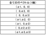
- FIG. 4 is a schematic diagram showing row vectors corresponding to all combinations when parameters in one wheel of the moving body 1 are reflected in control. Assuming that the weights for reflecting the wheel rotation angle ⁇ , the steering angle ⁇ , and the vertical position z in the control are real numbers other than 0, ⁇ 1, ⁇ 2, and ⁇ 3, respectively, as shown in FIG. There are seven combinations in all cases where parameters are reflected in control.
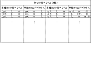
- FIG. 5 is a schematic diagram showing row vectors corresponding to all combinations when parameters in four wheels of the moving object 1 are reflected in control. In FIG.
- ⁇ 1 to ⁇ 12 are parameters of the wheel W1 (rotation angle ⁇ , steering angle ⁇ , vertical position z) and parameters of the wheel W2 (rotation angle ⁇ , steering angle ⁇ , vertical position z).
- the parameters of the wheel W3 (the rotation angle ⁇ , the steering angle ⁇ , the vertical position z), and the parameters of the wheel W4 (the rotation angle ⁇ , the steering angle ⁇ , the vertical position z) are weighted when each is reflected in the control. is there.
- the row vector shown in FIG. 5 indicates all parameters regarding which parameters of the four wheels are to be reflected in the control when controlling the rotation angle, the steering angle, and the vertical position of the wheels W1 to W4 of the moving object 1 respectively. Represents a combination.
- the vehicle control device 10 is configured by a vehicle-mounted computer (information processing device) including a processor 11, a memory 12, a storage device 13, and the like.
- the vehicle control device 10 selects a row vector corresponding to a target function in the moving object 1 from all row vectors for controlling the four wheels. In the present embodiment, which of the row vectors shown in FIG. 5 is to be selected is set in accordance with the function realized by the moving body 1.
- a row vector reflecting the steering angle ⁇ of the four wheels is selected as a row vector for calculating the steering angle ⁇ of each wheel.
- a row vector that reflects the steering angle ⁇ and the vertical position z of the four wheels in the control is selected. In this way, when a row vector is selected for each parameter corresponding to the degrees of freedom of the wheels W1 to W4, a transformation matrix X1 for realizing a target function in the moving body 1 is generated.
- the vehicle control device 10 generates a conversion matrix X2 by subjecting the generated conversion matrix X1 to block diagonalization, and controls the moving object 1 using the conversion matrix X2. Since the transformation matrix X2 is block diagonalized, the amount of calculation can be reduced, and it is also possible to perform distributed processing by a different processor for each block.
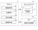
- FIG. 6 is a block diagram illustrating a functional configuration of the vehicle control device 10.
- the vehicle control device 10 includes a function setting unit 51, a row selection unit 52, a matrix generation unit 53, and a control execution unit 54 as functions of the processor 11. Further, a transformation matrix storage unit 61 is formed in the memory 12, and a row vector storage unit 71 is formed in the storage device 13.
- the conversion matrix storage unit 61 stores a conversion matrix generated in the vehicle control device 10 to realize a target function.
- the row vector storage unit 71 stores a list of row vectors representing all combinations of which parameters of the four wheels are to be reflected in the control.
- the function setting unit 51 sets a target function (a type of function) in the mobile unit 1.
- a manual setting mode in which a target function is manually set by a user and an automatic setting mode in which a target function is automatically set according to the traveling state of the mobile unit 1 are provided. It is prepared. Then, in the case of the manual setting mode, the function setting unit 51 sets the content set by the user as a target function.
- the function setting section 51 is an element that determines a traveling state such as a vehicle speed, a yaw rate, and a traveling environment (whether it is a highway or an urban area, a road surface state, or the like) of the moving body 1. The function associated in advance is set based on one or more of the above.
- the row selection unit 52 selects a row vector (function) corresponding to the set function from the list of row vectors stored in the row vector storage unit 71. (The row vector set as the one to be selected). At this time, the row selection unit 52 selects a row vector for each parameter (parameter to be controlled) corresponding to the degree of freedom of the operation of the moving object 1.
- the matrix generation unit 53 generates a transformation matrix X1 for realizing the set function based on the row vector selected by the row selection unit 52. Further, the matrix generation unit 53 sets the weight ⁇ of the element of each row vector in the generated transformation matrix.
- the state value of each parameter with respect to the input is calculated based on the row vector thus set, and the feedback control of each actuator is performed so as to follow the control target value set for the state value. For example, when steering the wheel W1 in the same phase as the wheel W2 by the same angle, the weight of the steering angle ⁇ of the wheel W1 is set to “ ⁇ 1”, and the weight of the steering angle ⁇ of the wheel W2 is set to “1”. It may be a row vector for calculating the state value of the steering angle ⁇ of the wheel W1.
- the actuator that controls the wheel W1 operates as the wheel W1. Is steered such that the steering wheel is steered in the same phase and at the same angle as the wheel W2.
- the matrix generation unit 53 generates a conversion matrix X2 by subjecting the generated conversion matrix X1 to block diagonalization.
- FIG. 7 is a schematic diagram illustrating a concept in which the transformation matrix X1 generated by the matrix generation unit 53 is block-diagonalized to generate the transformation matrix X2.
- ⁇ 1 to ⁇ 4, 11 to ⁇ 4, and Z1 to Z4 in the output are the state values of the wheel rotation angles ⁇ 1 to 44, the steering angles 11 to 44, and the vertical positions z1 to z4 in the input, respectively.
- Subscripts 1 to 4 indicate parameters corresponding to the wheels W1 to W4.
- ⁇ 1 to ⁇ 12 are input parameters of the wheel W1 ( ⁇ 1, ⁇ 1, z1), parameters of the wheel W2 ( ⁇ 2, ⁇ 2, z2), parameters of the wheel W3 ( ⁇ 3, ⁇ 3, z3), and parameters of the wheel W4 ( ⁇ 4, ⁇ 4, z4) are weights when each is reflected in control.
- the control execution unit 54 calculates a state value for each input parameter using the transformation matrix X2 generated by the matrix generation unit 53. As described above, a control target value is set for each of these state values, and the control execution unit 54 controls the input to each of the actuators so that the state value of each of the sequentially input parameters follows the control target value. (Current command value, etc.). That is, the control execution unit 54 performs feedback control on the elements of the behavior (parameters corresponding to the degrees of freedom) of the moving object 1 via the transformation matrix X2 that realizes the target function. Note that the control execution unit 54 may perform control using the transformation matrix X1 instead of the transformation matrix X2.
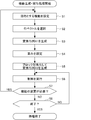
- FIG. 8 is a flowchart illustrating a flow of a function generation / execution process executed by the mobile unit 1.
- the function generation / execution processing is started in response to the mobile object 1 being turned on.
- step S1 the function setting unit 51 sets a target function in the mobile unit 1.
- step S2 the row selection unit 52 is associated with the set function from the list of row vectors stored in the row vector storage unit 71 based on the function set by the function setting unit 51. Select a row vector (a row vector set to be selected according to the function).
- step S3 the matrix generation unit 53 generates a transformation matrix X1 for realizing the set function based on the row vector selected by the row selection unit 52.
- step S4 the matrix generation unit 53 sets weights ⁇ k (k is a number representing a parameter corresponding to the degree of freedom) of each row vector element in the generated transformation matrix.
- step S5 the matrix generation unit 53 generates a conversion matrix X2 by subjecting the generated conversion matrix X1 to block diagonalization.
- step S6 the control execution unit 54 calculates a state value for each input parameter using the transformation matrix X2 generated by the matrix generation unit 53, and executes control of the mobile unit 1.
- step S7 the function setting unit 51 determines whether or not a function set in the mobile unit 1 needs to be changed. Whether the function set in the mobile unit 1 needs to be changed is determined, for example, by switching between the manual setting mode and the automatic setting mode, or by checking the running state of the mobile unit 1 in the automatic setting mode. It can be determined based on whether or not it has changed. If the function set in the moving object 1 needs to be changed, “YES” is determined in the step S7, and the process shifts to the step S1. On the other hand, when it is not necessary to change the function set in the mobile unit 1, NO is determined in step S7, and the process proceeds to step S8.
- step S8 the control execution unit 54 determines whether termination of the function generation / execution processing has been instructed. Whether or not the end of the function generation / execution processing has been instructed can be determined, for example, based on whether or not the mobile object 1 has been turned off. If the end of the function generation / execution processing is not instructed, NO is determined in step S8, and the processing shifts to step S6. On the other hand, when the end of the function generation / execution processing is instructed, YES is determined in step S8, and the function generation / execution processing ends.
- a row vector corresponding to a target function is selected from among row vectors corresponding to all combinations in a case where parameters of each wheel are reflected in control. Then, weights according to the target function are set for the elements of the transformation matrix formed by the selected row vectors, and the transformation matrix X1 is generated.
- the transformation matrix X1 is block-diagonalized, a transformation matrix X2 is generated, and the control of the moving object 1 is executed using the transformation matrix X2. Therefore, it is possible to dynamically generate a conversion matrix for realizing the target function set in the mobile unit 1. Therefore, a target function can be more flexibly realized in a device that performs a mechanical operation.
- the moving body 1 such as an automobile has been described as a specific example of the function generation device.
- the function generation device can be realized in the form of a work body that works on an object.
- FIG. 9 is a schematic diagram illustrating a configuration of the work body 2 according to an embodiment of the present invention.
- the work body 2 is realized as an example of a function generation device to which the present invention is applied, and is described here as a transport device that transports an object to be processed.
- Specific examples of the work body 1 include a transport device such as a sewing machine or a printer.
- the work body 2 can realize a function of transporting an object to be processed (such as cloth or paper) while squeezing, and a function of controlling the position of the object to be processed while applying tension thereto.
- the work body 2 can be an assembling machine or a power tool that rotates an object to be processed such as a screw, in addition to a transport device that transports an object to be processed.
- the work body 2 includes a first roller 101, a second roller 102, and a work control device 103.
- the first roller 101 and the second roller 102 include actuators according to the degree of freedom of operation.
- actuators for example, as illustrated in FIG. 9, rotation of each of the first roller 101 and the second roller 102 around the rotation axis, vertical translation when viewed from the rotation axis direction, and left and right It is possible to control the parallel movement in the directions, the relative movement in the torsional direction between the rotation axes of the first roller 101 and the second roller 102, and the like.
- the first roller 101 comes into contact with a first surface (for example, an upper surface) of the object to be processed, and rotates around a rotation axis to generate an object to be processed at a speed according to a rotation torque and a speed according to a rotation speed. Is moved on the first surface side. Further, the first roller 101 has a vertical parallel movement and a horizontal parallel movement when viewed from the rotation axis direction, and a relative movement of the rotation axis of the first roller 101 with respect to the rotation axis of the second roller 102 in the torsional direction. Each operation can be performed, and a parameter representing each operation can be reflected in control.
- a first surface for example, an upper surface
- the second roller 102 comes into contact with a second surface (for example, a lower surface) of the object to be processed, and rotates around a rotation axis to generate an object to be processed at a speed and a speed corresponding to a rotational torque. Is moved on the second surface side. Further, the second roller 102 is configured to perform a vertical parallel movement and a horizontal parallel movement when viewed from the rotation axis direction, and a relative movement of the rotation axis of the second roller 102 in the torsion direction with respect to the rotation axis of the first roller 101. Each operation can be performed, and a parameter representing each operation can be reflected in control.
- a second surface for example, a lower surface
- the work control device 103 is configured by a microcomputer (information processing device) including the processor 11, the memory 12, the storage device 13, and the like.
- the work control device 103 is, like the vehicle control device 10 in the above-described embodiment, selected from among all row vectors for controlling each actuator that operates the first roller 101 and each actuator that operates the second roller 102.
- a row vector corresponding to a desired function in the work body 2 is selected.
- the rotation angle of the first roller 101 and the second roller All combinations of whether the rotation angle of 102 is reflected in the control are (1, 0), (0, 1), and (1, 1).
- the rotation speeds of the first roller 101 and the second roller 102 are controlled in the same direction, and the first roller 101 and the second roller
- the rotation torque of the roller 102 needs to be controlled in the opposite direction.
- the transformation matrix X3 shown in FIG. 9 is generated.
- a state value with respect to the input parameters (the rotation angle of the first roller 101 and the rotation angle of the second roller 102) is calculated so that the state value follows the control target value set for the state value.
- the function of the work body 2 transporting the object to be processed while ironing it can be realized. With such a function, for example, a task of picking up and conveying only one sheet to be fed from a bundle of printing sheets set in the printer can be more reliably executed.
- a transformation matrix can be dynamically generated by selecting a row vector corresponding to a target function.
- a conversion matrix for performing the straight stitching is generated, the straight stitching is performed, and the mode is changed to the mode in which the decorative stitching is performed.
- the functional configuration of the work control device 106 and the operation of the work body 2 are almost the same as those of the above-described embodiment except that the specific example of the target function is different.
- the basic principle of the present invention can be applied to various devices such as the work body 2 that works on an object, in addition to the moving body 1 such as an automobile, and specific device forms to which the present invention is applied.
- the target function can be more flexibly realized in the device that performs the mechanical operation.
- the moving object 1 includes the function setting unit 51, the row selection unit 52, and the matrix generation unit 53.
- the function setting unit 51 sets a target function in a device to be controlled.
- the row selection unit 52 selects a data string corresponding to the function set by the function setting unit 51 from among data strings representing a plurality of combinations of parameters that can be reflected in control in the device to be controlled.
- the matrix generation unit 53 generates a conversion matrix corresponding to a target function, using the data string selected by the row selection unit 52 as an element.
- a target function can be flexibly realized in a device that performs a mechanical operation.
- the matrix generation unit 53 sets weights on the elements of the transformation matrix according to the desired function. With this, various reflection methods can be set for the parameters to be reflected in the control, so that various functions can be realized.
- the matrix generation unit 53 performs block diagonalization on the transformation matrix. Thereby, when controlling the device to be controlled, the calculation becomes simple, so that the amount of calculation can be reduced. Further, distributed processing can be performed by a different processor for each block in the transformation matrix.
- the mobile unit 1 includes a control execution unit 54.
- the control execution unit 54 controls the device to be controlled based on the transformation matrix generated by the matrix generation unit 53. This makes it possible to execute control of a device to be controlled by using a transformation matrix dynamically generated to realize a target function.
- the function setting unit 51 determines whether the target function needs to be changed in the device to be controlled, and changes the target function when it determines that the target function needs to be changed. Thus, when it becomes necessary to change a target function in a device to be controlled, it becomes possible to perform control by switching necessary functions as appropriate.
- the present invention is not limited to the above-described embodiment, but includes modifications and improvements as long as the object of the present invention can be achieved.
- the function generation device is realized as a moving body such as an automobile
- the present invention is not limited to this. That is, the present invention can be applied to a case where a physical quantity such as a position, a speed, or a force is controlled in a device that performs a mechanical operation.
- the present invention can be applied to a case where various functions are realized in an apparatus that performs various mechanical operations such as a drone, an aircraft, a submarine, and a ship.
- row vector candidates are stored in advance, but the present invention is not limited to this. That is, row vector candidates may be appropriately generated at necessary timing, and a row vector suitable for a target function may be selected from the generated row vectors.
- the processing in the above-described embodiment can be executed by any of hardware and software. That is, it is only necessary that the function generating apparatus has a function capable of executing the above-described processing, and what kind of functional configuration and hardware configuration are required to realize this function is not limited to the above-described example.
- a program constituting the software is installed on a computer from a network or a storage medium.
- the storage medium for storing the program is constituted by a removable medium distributed separately from the apparatus main body, a storage medium incorporated in the apparatus main body in advance, or the like.
- the removable medium is constituted by, for example, a magnetic disk, an optical disk, a magneto-optical disk, or the like.
- the optical disc is composed of, for example, a CD-ROM (Compact Disc-Read Only Memory), a DVD (Digital Versatile Disc), a Blu-ray Disc (registered trademark), and the like.
- the magneto-optical disk is composed of an MD (Mini-Disk) or the like.
- the storage medium pre-installed in the apparatus main body is constituted by, for example, a ROM (Read Only Memory) in which a program is stored, a hard disk, or the like.
Landscapes
- Engineering & Computer Science (AREA)
- Physics & Mathematics (AREA)
- General Physics & Mathematics (AREA)
- Theoretical Computer Science (AREA)
- Mathematical Physics (AREA)
- General Engineering & Computer Science (AREA)
- Pure & Applied Mathematics (AREA)
- Computational Mathematics (AREA)
- Data Mining & Analysis (AREA)
- Mathematical Analysis (AREA)
- Mathematical Optimization (AREA)
- Software Systems (AREA)
- Databases & Information Systems (AREA)
- Algebra (AREA)
- Computing Systems (AREA)
- Automation & Control Theory (AREA)
- Manufacturing & Machinery (AREA)
- Human Computer Interaction (AREA)
- Steering Control In Accordance With Driving Conditions (AREA)
- Feedback Control In General (AREA)
- Control Of Position, Course, Altitude, Or Attitude Of Moving Bodies (AREA)
- Health & Medical Sciences (AREA)
- Artificial Intelligence (AREA)
- Computer Vision & Pattern Recognition (AREA)
- Evolutionary Computation (AREA)
- Medical Informatics (AREA)
Abstract
Description
このような装置は、例えば、電動モータや油圧システム等によって構成されるアクチュエータにより、装置が備える機構の機械的な挙動が制御される。
例えば、自動車においては、車輪の路面に対する回転(転動)がモータによって制御されると共に、車輪の向きが操舵装置によって制御され、さらに、車輪の鉛直方向の動きがサスペンション装置によって制御される。
また、同様に、ミシンあるいはプリンタ等においては、処理対象の物体(布や紙等)の移動が搬送装置によって制御される。
このような装置は、概して、アクチュエータによって環境に作用しながら、目的とする機能を発揮するものである。
即ち、装置が有する動作の自由度に対応してアクチュエータが備えられ、このアクチュエータによって制御される機械要素が環境に作用することで、装置の挙動を表す特定のパラメータが決定付けられる。
そのため、機械的な動作を行う装置においては、いずれのアクチュエータをどのように制御するかによって、その装置において実現される機能が変化することとなる。
ここで、特許文献1には、制御対象システムの機能に応じて設定される速度(位置)及び力の領域への制御エネルギーの座標変換を定義し、定義された座標変換を介して速度(位置)及び力の制御を行うことで、目的とする機能を実現する位置・力制御装置が開示されている。
一方、制御対象システムにおいて目的とする機能は、多様に変化する可能性があり、これらに応じた座標変換を予め用意しておくことは必ずしも容易ではない。
このように、従来、機械的な動作を行う装置において、目的とする機能を柔軟に実現することは困難であった。
本発明の課題は、機械的な動作を行う装置において、目的とする機能を柔軟に実現することである。
制御対象となる装置における目的とする機能を設定する機能設定手段と、
前記制御対象となる装置において制御に反映させることが可能なパラメータの複数の組み合わせを表すデータ列の中から、前記機能設定手段によって設定された機能に対応するデータ列を選択するデータ列選択手段と、
前記データ列選択手段によって選択されたデータ列によって前記目的とする機能に対応する変換行列を生成する行列生成手段と、
を備えることを特徴とする。
初めに、本発明に係る機能生成装置、機能生成方法及びプログラムに適用される基本的原理について説明する。
本発明においては、目的とする機能に応じた速度(位置)及び力の領域への制御エネルギーの座標変換を定義し、定義された座標変換を介して速度(位置)及び力の少なくともいずれかの制御を行うことで、機械的な動作を行う装置において目的とする機能を実現することを前提としている。即ち、本発明においては、例えば、国際公開第2015/041046号に記載されている速度(位置)及び力の制御手法に基づく制御を用いることができる。
そこで、本発明においては、当該装置の挙動の要素となるパラメータ(物理量)の全ての組み合わせを行ベクトル(データ列)として用意し、これらの行ベクトルの中から、当該装置において目的とする機能に適合する特定の行ベクトルを選択して変換行列を構成することで、目的とする機能に応じて設定される速度(位置)及び力の領域への制御エネルギーの座標変換を定義する。
機械的な動作を行う装置において、動作の自由度が3である場合、当該装置の挙動の要素となるパラメータ(動作を表すパラメータ)として、第1の自由度に対応するパラメータP1、第2の自由度に対応するパラメータP2及び第3の自由度に対応するパラメータP3が取得される。
これら全ての行ベクトルのうち、例えば、パラメータP1のみを制御に反映させ、パラメータP2,P3を制御に反映させない場合、図1の「行ベクトルの候補」における第1行(1,0,0)が選択される。
また、例えば、パラメータP1,P2を制御に反映させ、パラメータP3を制御に反映させない場合、図1の「行ベクトルの候補」における第4行(1,1,0)が選択される。
なお、図1に示すように行ベクトルを選択する場合、複数の行において同一の行ベクトルを選択することも可能である。
また、実際に制御のための処理を実行する場合には、制御に反映させるパラメータの行ベクトルの要素「1」に重みを設定して「α」(αは0以外の実数)とした変換行列を構成することができる。
即ち、機械的な動作を行う装置において挙動の要素となるパラメータの状態に対応して、特定の自由度に対応するアクチュエータが制御される。
この結果、機械的な動作を行う装置における特定の挙動の要素(特定の自由度に対応するパラメータ)に関するフィードバック制御を構成することができ、目的とする機能が実現されることとなる。
したがって、本発明によれば、機械的な動作を行う装置において、目的とする機能を柔軟に実現することが可能となる。
以下、本発明を適用した機能生成装置の実施形態について具体的に説明する。
図2は、本発明の一実施形態に係る移動体1の構成を示す模式図である。
移動体1は、本発明を適用した機能生成装置の一例として実現されるものであり、ここでは4輪が独立して回転、操舵及びサスペンションの制御を行うことが可能な車両であるものとして説明する。移動体1の具体例としては、自動車、電動車椅子、製造ラインで物品を運搬する台車、フォークリフト、ゴルフ場等で使用されるカート等、複数の車輪を有する装置を挙げることができる。
図2に示すように、移動体1は、前後左右の車輪W1~W4と、移動体1全体を制御する車両制御装置10とを備えている。なお、図示は省略するが、移動体1には、操舵を行うためのハンドル、加速を行うためのアクセルペダル、減速を行うためのブレーキペダル等、移動体1を構成するために必要な各種装置が備えられている。
図3に示すように、移動体1の各車輪は、車輪の回転、車輪の操舵、車輪の鉛直方向の位置(サスペンション)をそれぞれ制御可能な構成(3自由度)を有している。
図3に示す構成において、移動体1の各車輪には、車輪の回転角度θ、操舵角度ω及び鉛直方向の位置zをそれぞれ検出するセンサD1~D3が備えられており、センサD1~D3による検出結果は、逐次、車両制御装置10に入力される。
ここで、車輪の回転角度θ、操舵角度ω及び鉛直方向の位置zのいずれを反映させて制御を行うかについて、図1と同様に、全ての組み合わせに対応する行ベクトルを定義することができる。なお、制御に反映させる際には、車輪の回転角度θ、操舵角度ω及び鉛直方向の位置zを適宜、微分あるいは積分する等、相互に置換可能なパラメータを取得して入力とすることも可能である。
車輪の回転角度θ、操舵角度ω及び鉛直方向の位置zを制御に反映させる場合の重みを、それぞれ0以外の実数であるα1、α2、α3とすると、図4に示すように、1輪におけるパラメータを制御に反映させる場合の全ての組み合わせは7通りとなる。
また、図5は、移動体1の4輪におけるパラメータを制御に反映させる場合の全ての組み合わせに対応する行ベクトルを示す模式図である。
なお、図5において、α1~α12は、車輪W1のパラメータ(回転角度θ、操舵角度φ、鉛直方向の位置z)、車輪W2のパラメータ(回転角度θ、操舵角度φ、鉛直方向の位置z)、車輪W3のパラメータ(回転角度θ、操舵角度φ、鉛直方向の位置z)、車輪W4のパラメータ(回転角度θ、操舵角度φ、鉛直方向の位置z)それぞれを制御に反映させる場合の重みである。
図5に示す行ベクトルは、移動体1の車輪W1~W4における回転角度、操舵角度及び鉛直方向の位置をそれぞれ制御する場合に、4輪におけるいずれのパラメータを制御に反映させるかについての全ての組み合わせを表している。
車両制御装置10は、4輪の制御のための全ての行ベクトルの中から、移動体1において目的とする機能に応じた行ベクトルを選択する。
本実施形態においては、移動体1で実現される機能に応じて、図5に示す行ベクトルのうち、いずれを選択すべきであるかが設定されている。
また、4輪の操舵制御を行い、かつ、旋回時のロール角を制御する場合、4輪の操舵角度ω及び鉛直方向の位置zをそれぞれ制御に反映させる行ベクトルが選択される。
このようにして、車輪W1~W4の自由度に対応する各パラメータについて、行ベクトルが選択されると、移動体1において目的とする機能を実現するための変換行列X1が生成される。
変換行列X2は、ブロック対角化されていることから、演算量を低減させることができると共に、ブロック毎に異なるプロセッサで分散処理すること等も可能となる。
図6は、車両制御装置10の機能的構成を示すブロック図である。
図6に示すように、車両制御装置10は、プロセッサ11の機能として、機能設定部51と、行選択部52と、行列生成部53と、制御実行部54と、を備えている。また、メモリ12には、変換行列記憶部61が形成され、ストレージデバイス13には、行ベクトル記憶部71が形成される。
行ベクトル記憶部71には、4輪におけるいずれのパラメータを制御に反映させるかについての全ての組み合わせを表す行ベクトルの一覧が記憶される。
また、行列生成部53は、生成した変換行列において、各行ベクトルの要素の重みαをそれぞれ設定する。
図7は、行列生成部53によって生成された変換行列X1がブロック対角化されて変換行列X2が生成される概念を示す模式図である。
なお、図7において、出力におけるΘ1~Θ4、Φ1~Φ4、Z1~Z4は、それぞれ入力における車輪の回転角度θ1~θ4、操舵角度φ1~φ4、鉛直方向の位置z1~z4の状態値であり、添え字1~4は車輪W1~W4に対応するパラメータであることを示している。また、α1~α12は、入力における車輪W1のパラメータ(θ1、φ1、z1)、車輪W2のパラメータ(θ2、φ2、z2)、車輪W3のパラメータ(θ3、φ3、z3)、車輪W4のパラメータ(θ4、φ4、z4)それぞれを制御に反映させる場合の重みである。
なお、制御実行部54は、変換行列X2に代えて、変換行列X1を用いて制御を行うこととしてもよい。
次に、移動体1の動作を説明する。
図8は、移動体1が実行する機能生成・実行処理の流れを説明するフローチャートである。
機能生成・実行処理は、移動体1がイグニションオンとされることに対応して開始される。
ステップS2において、行選択部52は、機能設定部51によって設定された機能に基づいて、行ベクトル記憶部71に記憶された行ベクトルの一覧の中から、設定された機能に対応付けられている行ベクトル(機能に応じて選択すべきものとして設定された行ベクトル)を選択する。
ステップS3において、行列生成部53は、行選択部52によって選択された行ベクトルによって、設定された機能を実現するための変換行列X1を生成する。
ステップS5において、行列生成部53は、生成した変換行列X1をブロック対角化することにより、変換行列X2を生成する。
ステップS6において、制御実行部54は、行列生成部53によって生成された変換行列X2を用いて、入力される各パラメータに対する状態値を算出し、移動体1の制御を実行する。
移動体1において設定されている機能の変更が必要である場合、ステップS7においてYESと判定されて、処理はステップS1に移行する。
一方、移動体1において設定されている機能の変更が必要でない場合、ステップS7においてNOと判定されて、処理はステップS8に移行する。
機能生成・実行処理の終了が指示されていない場合、ステップS8においてNOと判定されて、処理はステップS6に移行する。
一方、機能生成・実行処理の終了が指示された場合、ステップS8においてYESと判定されて、機能生成・実行処理は終了となる。
そして、選択された行ベクトルによって構成された変換行列の要素に対して、目的とする機能に応じた重みが設定され、変換行列X1が生成される。
そのため、移動体1において設定された目的とする機能を実現するための変換行列を動的に生成することができる。
したがって、機械的な動作を行う装置において、目的とする機能をより柔軟に実現することが可能となる。
上述の実施形態において、機能生成装置の具体例として、自動車等の移動体1を例に挙げて説明したが、これに限られない。
例えば、機能生成装置は、物体に対する作業を行う作業体の形態で実現することもできる。
作業体2は、本発明を適用した機能生成装置の一例として実現されるものであり、ここでは、処理対象の物体を搬送する搬送装置であるものとして説明する。作業体1の具体例としては、ミシンあるいはプリンタ等の搬送装置を挙げることができる。作業体2により、処理対象の物体(布や紙等)をしごきながら搬送する機能や、処理対象の物体にテンションを加えながら位置を制御する機能を実現することができる。なお、作業体2は、処理対象の物体を搬送する搬送装置の他、ねじ等の処理対象の物体を回転させる組み立て機械や電動工具等とすることも可能である。
作業制御装置103は、上述の実施形態における車両制御装置10と同様に、第1ローラ101を動作させる各アクチュエータ及び第2ローラ102を動作させる各アクチュエータの制御のための全ての行ベクトルの中から、作業体2において目的とする機能に応じた行ベクトルを選択する。
一例として、作業体2が、第1ローラ101の回転軸周りの回転及び第2ローラ102の回転軸周りの回転の2自由度を有するものとすると、第1ローラ101の回転角度及び第2ローラ102の回転角度を制御に反映させるかについての全ての組み合わせは、(1,0)、(0,1)、(1,1)の3通りとなる。
(β1,0)
(0,β2)
(β1,β2)
となる。
このとき、第1ローラ101及び第2ローラ102の回転速度を制御するために、(β1,β2)の行ベクトルが選択され、重みβ1=1、β2=1が設定される。
また、第1ローラ101及び第2ローラ102の回転トルクを制御するために、(β1,β2)の行ベクトルが選択され、重みβ1=1、β2=-1が設定される。
変換行列X3を用いて、入力されたパラメータ(第1ローラ101の回転角度及び第2ローラ102の回転角度)に対する状態値を算出し、状態値に対して設定された制御目標値に追従するように制御を行うことにより、作業体2が処理対象の物体をしごきながら搬送する機能を実現することができる。このような機能により、例えば、プリンタにセットされた印刷用紙の束から、給紙すべき1枚のみをピックアップして搬送する作業をより確実に実行することができる。
また、作業体2において、異なる機能を実現する場合には、目的とする機能に応じた行ベクトルをそれぞれ選択することにより、変換行列を動的に生成することができる。このような機能により、例えば、ミシンにおいて、標準的な直線縫いのモードが設定された場合には、直線縫いを行うための変換行列を生成して直線縫いを実行し、飾り縫いを行うモードに切り替えられた場合には、飾り縫いを行うための変換行列を生成して飾り縫いを実行すること等が可能となる。
このように、本発明の基本的原理は、自動車等の移動体1の他、物体に対する作業を行う作業体2等の各種装置に適用可能であり、本発明が適用される具体的な装置形態に応じた機能生成装置とすることができる。
これにより、機械的な動作を行う装置において、目的とする機能をより柔軟に実現することができる。
上述の実施形態において、目的とする機能を実現するための変換行列の生成と、生成した変換行列による制御対象となる装置の制御とを同一の装置(移動体1)で実行する場合を例に挙げて説明したが、これに限られない。
即ち、本発明を適用した機能生成装置において、目的とする機能を実現するための変換行列の生成のみを行い、生成した変換行列を制御対象となる他の装置に出力して、制御対象となる装置において、変換行列による制御を行うこととしてもよい。
機能設定部51は、制御対象となる装置における目的とする機能を設定する。
行選択部52は、制御対象となる装置において制御に反映させることが可能なパラメータの複数の組み合わせを表すデータ列の中から、機能設定部51によって設定された機能に対応するデータ列を選択する。
行列生成部53は、行選択部52によって選択されたデータ列を要素として目的とする機能に対応する変換行列を生成する。
これにより、機械的な動作を行う装置で制御に反映させ得るパラメータの複数の組み合わせを表す行ベクトルの中から、当該装置において目的とする機能に適合する特定の行ベクトルを選択して変換行列が構成される。
したがって、本発明によれば、機械的な動作を行う装置において、目的とする機能を柔軟に実現することが可能となる。
これにより、制御に反映させるパラメータについて、その反映方法を種々設定することができるため、多様な機能を実現することが可能となる。
これにより、制御対象となる装置を制御する際に、演算が簡単なものとなるため、演算量を低減させることができる。また、変換行列におけるブロック毎に異なるプロセッサで分散処理すること等が可能となる。
制御実行部54は、行列生成部53によって生成された変換行列に基づいて、制御対象となる装置の制御を実行する。
これにより、目的とする機能を実現するために動的に生成された変換行列によって、制御対象となる装置の制御を実行することが可能となる。
これにより、制御対象となる装置において目的とする機能を変更する必要が生じた場合に、必要な機能を適宜切り替えて制御を行うことが可能となる。
例えば、上述の実施形態においては、機能生成装置を自動車等の移動体として実現する場合を例に挙げて説明したが、これに限られない。即ち、機械的な動作を行う装置において、位置、速度あるいは力等の物理量を制御する場合に本発明を適用することができる。例えば、本発明は、ドローン、航空機、潜水艦、あるいは、船舶等、種々の機械的な動作を行う装置において、各種機能を実現する場合に適用することが可能である。
即ち、上述の処理を実行できる機能が機能生成装置に備えられていればよく、この機能を実現するためにどのような機能構成及びハードウェア構成とするかは上述の例に限定されない。
上述の処理をソフトウェアにより実行させる場合には、そのソフトウェアを構成するプログラムが、コンピュータにネットワークや記憶媒体からインストールされる。
Claims (7)
- 制御対象となる装置における目的とする機能を設定する機能設定手段と、
前記制御対象となる装置において制御に反映させることが可能なパラメータの複数の組み合わせを表すデータ列の中から、前記機能設定手段によって設定された機能に対応するデータ列を選択するデータ列選択手段と、
前記データ列選択手段によって選択されたデータ列を要素として前記目的とする機能に対応する変換行列を生成する行列生成手段と、
を備えることを特徴とする機能生成装置。 - 前記行列生成手段は、前記目的とする機能に応じて前記変換行列の要素に重みを設定することを特徴とする請求項1に記載の機能生成装置。
- 前記行列生成手段は、前記変換行列をブロック対角化することを特徴とする請求項1または2に記載の機能生成装置。
- 前記行列生成手段によって生成された前記変換行列に基づいて、前記制御対象となる装置の制御を実行する制御実行手段を備えることを特徴とする請求項1から3のいずれか1項に記載の機能生成装置。
- 前記機能設定手段は、前記制御対象となる装置において目的とする機能に変更が必要であるか否かを判定し、変更が必要であると判定した場合に、当該目的とする機能を変更することを特徴とする請求項1から4のいずれか1項に記載の機能生成装置。
- 情報処理装置において実行される機能生成方法であって、
制御対象となる装置における目的とする機能を設定する機能設定ステップと、
前記制御対象となる装置において制御に反映させることが可能なパラメータの複数の組み合わせを表すデータ列の中から、前記機能設定ステップにおいて設定された機能に対応するデータ列を選択するデータ列選択ステップと、
前記データ列選択ステップにおいて選択されたデータ列によって前記目的とする機能に対応する変換行列を生成する行列生成ステップと、
を含むことを特徴とする機能生成方法。 - コンピュータを、
制御対象となる装置における目的とする機能を設定する機能設定手段、
前記制御対象となる装置において制御に反映させることが可能なパラメータの複数の組み合わせを表すデータ列の中から、前記機能設定手段によって設定された機能に対応するデータ列を選択するデータ列選択手段、
前記データ列選択手段によって選択されたデータ列によって前記目的とする機能に対応する変換行列を生成する行列生成手段、
として機能させることを特徴とするプログラム。
Priority Applications (2)
| Application Number | Priority Date | Filing Date | Title |
|---|---|---|---|
| JP2020541216A JP7369383B2 (ja) | 2018-09-03 | 2019-09-02 | 機能生成装置、機能生成方法及びプログラム |
| US17/272,439 US12299066B2 (en) | 2018-09-03 | 2019-09-02 | Function generation apparatus, method for generating function, and storage medium |
Applications Claiming Priority (2)
| Application Number | Priority Date | Filing Date | Title |
|---|---|---|---|
| JP2018164836 | 2018-09-03 | ||
| JP2018-164836 | 2018-09-03 |
Publications (1)
| Publication Number | Publication Date |
|---|---|
| WO2020050232A1 true WO2020050232A1 (ja) | 2020-03-12 |
Family
ID=69721639
Family Applications (1)
| Application Number | Title | Priority Date | Filing Date |
|---|---|---|---|
| PCT/JP2019/034494 Ceased WO2020050232A1 (ja) | 2018-09-03 | 2019-09-02 | 機能生成装置、機能生成方法及びプログラム |
Country Status (3)
| Country | Link |
|---|---|
| US (1) | US12299066B2 (ja) |
| JP (1) | JP7369383B2 (ja) |
| WO (1) | WO2020050232A1 (ja) |
Families Citing this family (5)
| Publication number | Priority date | Publication date | Assignee | Title |
|---|---|---|---|---|
| US12111966B2 (en) | 2020-02-27 | 2024-10-08 | Keio University | Position/force control system, worn unit, control unit, position/force control method, and storage medium |
| JP7730107B2 (ja) | 2020-02-27 | 2025-08-27 | 慶應義塾 | 習得支援システム、習得支援方法、及び習得支援プログラム |
| JP7679178B2 (ja) | 2020-03-31 | 2025-05-19 | 地方独立行政法人神奈川県立産業技術総合研究所 | 医療用ドリル、及び医療用プログラム |
| JPWO2022230594A1 (ja) * | 2021-04-26 | 2022-11-03 | ||
| JPWO2022270319A1 (ja) | 2021-06-25 | 2022-12-29 |
Citations (3)
| Publication number | Priority date | Publication date | Assignee | Title |
|---|---|---|---|---|
| JPH08145007A (ja) * | 1994-11-18 | 1996-06-04 | Toshio Fukuda | アクチュエータの作動方法及び装置 |
| JP2002312003A (ja) * | 2001-04-13 | 2002-10-25 | Yaskawa Electric Corp | サーボ制御方法 |
| WO2015041046A1 (ja) * | 2013-09-19 | 2015-03-26 | 学校法人慶應義塾 | 位置・力制御装置、位置・力制御方法及びプログラム |
Family Cites Families (2)
| Publication number | Priority date | Publication date | Assignee | Title |
|---|---|---|---|---|
| JP6464204B2 (ja) * | 2017-01-17 | 2019-02-06 | ファナック株式会社 | オフラインプログラミング装置及び位置パラメータ補正方法 |
| JP7018759B2 (ja) | 2017-12-14 | 2022-02-14 | 学校法人慶應義塾 | 位置・力制御装置 |
-
2019
- 2019-09-02 US US17/272,439 patent/US12299066B2/en active Active
- 2019-09-02 JP JP2020541216A patent/JP7369383B2/ja active Active
- 2019-09-02 WO PCT/JP2019/034494 patent/WO2020050232A1/ja not_active Ceased
Patent Citations (3)
| Publication number | Priority date | Publication date | Assignee | Title |
|---|---|---|---|---|
| JPH08145007A (ja) * | 1994-11-18 | 1996-06-04 | Toshio Fukuda | アクチュエータの作動方法及び装置 |
| JP2002312003A (ja) * | 2001-04-13 | 2002-10-25 | Yaskawa Electric Corp | サーボ制御方法 |
| WO2015041046A1 (ja) * | 2013-09-19 | 2015-03-26 | 学校法人慶應義塾 | 位置・力制御装置、位置・力制御方法及びプログラム |
Also Published As
| Publication number | Publication date |
|---|---|
| JP7369383B2 (ja) | 2023-10-26 |
| US12299066B2 (en) | 2025-05-13 |
| US20210334336A1 (en) | 2021-10-28 |
| JPWO2020050232A1 (ja) | 2021-11-11 |
Similar Documents
| Publication | Publication Date | Title |
|---|---|---|
| JP7369383B2 (ja) | 機能生成装置、機能生成方法及びプログラム | |
| JP4697254B2 (ja) | 車両挙動制御装置 | |
| CN114655248A (zh) | 自动驾驶车辆的横向控制方法、装置及车辆 | |
| JP3785445B2 (ja) | 電動パワーステアリング制御装置の制御パラメータ調整教示装置、及び制御パラメータ調整教示システム | |
| CN101842279A (zh) | 转向控制装置以及使用其的车辆用转向装置 | |
| KR20220118912A (ko) | 조향 휠에 개선된 피드백을 제공하도록 스티어-바이-와이어 시스템을 제어하기 위한 장치 및 방법 | |
| US11235834B2 (en) | Leaning vehicle | |
| JP7724976B2 (ja) | 車両のモーションを制御するためのシステムおよび方法 | |
| WO2006013922A1 (ja) | 車両の制御装置 | |
| JP3901928B2 (ja) | 電動パワーステアリング装置の制御装置 | |
| JP6281594B2 (ja) | 走行装置、走行装置の制御方法および走行装置の制御プログラム | |
| KR101441887B1 (ko) | 이동방향 제어장치 및 컴퓨터 프로그램 | |
| CN109177744A (zh) | 一种车道偏离辅助控制系统的转矩分配控制方法 | |
| US6540044B1 (en) | Regulating system | |
| CN109291806A (zh) | 轮毂电机驱动汽车的车道偏离辅助控制系统及控制方法 | |
| JP5181563B2 (ja) | 車両用操舵装置 | |
| JP2019217867A (ja) | 車両用操舵装置 | |
| Li et al. | Human–machine cooperative steering control based on non-cooperative Nash game | |
| JPH05111889A (ja) | 制御方式可変型ロボツト制御方式 | |
| JP4639985B2 (ja) | 車両の操舵制御装置 | |
| JP2023168269A (ja) | 道路車両用の制御システムおよび関連する制御方法 | |
| JP7099056B2 (ja) | 操舵制御装置 | |
| CN120963673A (zh) | 车轮转向模式切换方法及相关设备 | |
| Faryński et al. | Study of the problem and the idea of operation of four-wheel-steering cars | |
| Bünte et al. | Human machine interface concept for interactive motion control of a highly maneuverable robotic vehicle |
Legal Events
| Date | Code | Title | Description |
|---|---|---|---|
| 121 | Ep: the epo has been informed by wipo that ep was designated in this application |
Ref document number: 19858095 Country of ref document: EP Kind code of ref document: A1 |
|
| ENP | Entry into the national phase |
Ref document number: 2020541216 Country of ref document: JP Kind code of ref document: A |
|
| NENP | Non-entry into the national phase |
Ref country code: DE |
|
| 122 | Ep: pct application non-entry in european phase |
Ref document number: 19858095 Country of ref document: EP Kind code of ref document: A1 |
|
| WWG | Wipo information: grant in national office |
Ref document number: 17272439 Country of ref document: US |