WO2020045583A1 - 氷充填率計測装置、氷充填率計測方法、およびスラリーアイス製造機 - Google Patents
氷充填率計測装置、氷充填率計測方法、およびスラリーアイス製造機 Download PDFInfo
- Publication number
- WO2020045583A1 WO2020045583A1 PCT/JP2019/033978 JP2019033978W WO2020045583A1 WO 2020045583 A1 WO2020045583 A1 WO 2020045583A1 JP 2019033978 W JP2019033978 W JP 2019033978W WO 2020045583 A1 WO2020045583 A1 WO 2020045583A1
- Authority
- WO
- WIPO (PCT)
- Prior art keywords
- ice
- light source
- receiving sensor
- tank
- light
- Prior art date
- Legal status (The legal status is an assumption and is not a legal conclusion. Google has not performed a legal analysis and makes no representation as to the accuracy of the status listed.)
- Ceased
Links
Images











Classifications
-
- F—MECHANICAL ENGINEERING; LIGHTING; HEATING; WEAPONS; BLASTING
- F25—REFRIGERATION OR COOLING; COMBINED HEATING AND REFRIGERATION SYSTEMS; HEAT PUMP SYSTEMS; MANUFACTURE OR STORAGE OF ICE; LIQUEFACTION SOLIDIFICATION OF GASES
- F25C—PRODUCING, WORKING OR HANDLING ICE
- F25C1/00—Producing ice
-
- G—PHYSICS
- G01—MEASURING; TESTING
- G01N—INVESTIGATING OR ANALYSING MATERIALS BY DETERMINING THEIR CHEMICAL OR PHYSICAL PROPERTIES
- G01N21/00—Investigating or analysing materials by the use of optical means, i.e. using sub-millimetre waves, infrared, visible or ultraviolet light
- G01N21/17—Systems in which incident light is modified in accordance with the properties of the material investigated
- G01N21/59—Transmissivity
Definitions
- the present invention relates to a slurry ice making machine for producing slurry ice, an ice filling rate measuring device for measuring an ice filling factor (IPF) of the slurry ice, and an ice filling rate measuring method.
- IPF ice filling factor
- Slurry ice is liquid ice in which spherical ice is mixed with seawater, fresh water, seasoning liquid, and the like, and is mainly used to maintain the freshness of fresh food products, which was impossible with conventional ice.
- ice particles having a diameter of about 100 ⁇ m are mixed in cold water (for example, 0 ° C. to ⁇ 6 ° C.) such as diluted seawater or an aqueous NaCl solution.
- the temperature is determined by the salt concentration, the diameter of the ice particles of the slurry ice, and the ratio of the amount of salt water.
- the salt concentration of seawater is between -1.5 ° C. and -3.5 ° C. .
- Slurry ice is characterized by its fineness and large surface area. Therefore, for example, when slurry ice is used to maintain the freshness of fish, it can quickly take away the heat of the fish, promote bleeding due to the difference in osmotic pressure, and eliminate the deterioration due to the propagation of various bacteria from the moment the fish is squeezed. It is. In other words, the commercial value can be increased by using the slurry ice. Further, since fine ice enters small gaps, it can be applied to a cooled object such as a crab, sea urchin, or shellfish, which has a shape that is difficult to cool.
- Slurry ice is also used for rapid cooling after boiler broilers and rapid cooling immediately after harvesting broccoli, etc., and has contributed to solving problems such as drying in conventional refrigerators and heavy labor in handling ice. .
- slurry ice can also exhibit more performance than both as a buffer and a coolant, it can transport sea urchins with shells, vulnerable sweet breams, and true cod, which were previously difficult to ship. became.
- Slurry ice is generated so as to achieve an appropriate ice filling factor (hereinafter, also referred to as “IPF”) depending on its use.
- IPF ice filling factor
- Non-Patent Documents 1 and 4 methods for measuring IPF include a method based on changes in electrical characteristics such as capacitance and electric conductivity (hereinafter, referred to as a “first method”), As disclosed in Non-Patent Document 2, a method using ultrasonic waves and based on the attenuation rate (hereinafter, referred to as “second method”), or as disclosed in Non-Patent Document 3, There are various methods such as a method called a volume method based on a change in the amount of ice measured from a water level in a tank in the ice making machine (hereinafter, referred to as a “third method”).
- Non-Patent Document 1 Katsuya Kun et al., "Study on IPF Measuring Device in Pipe in Ice Water Transport", Proceedings of the Society of Air Conditioning and Sanitary Engineers, Vol. 1997, no. Pt3, 1125-1128, (1997) (Non-Patent Document 2) Tomomasa Imai et al., “Basic Study on Ice Water Transfer System (3rd Report) Study of IPF Measurement Method in Pipe Using Ultrasound", Proceedings of the Air Conditioning and Sanitary Engineering Society Conference, Vol. 1997, no. Pt3, pp. 1171-1120, (1997) (Non-Patent Document 3) Jonathan D. WEST et al.
- Non-Patent Document 4 “Performance of a Volumetric Method for Measuring State of Charge for Ice Storage System”, ASHRAE Trans (Am Soc Heat Refrig Air Cond Eng), Vol.105, No.Pt2, page 318-324, (1999)
- Non-Patent Document 4 Akihiko Horibe et al., “Methods for Measuring Various Ice Filling Rates of Ice-Water Slurry," Proceedings of the JSME Chugoku-Shikoku Branch General Meeting and Lectures, Vol. 37, 227-228, (1999)
- the above-described first and third methods have a problem that the measurement accuracy is low, and the second method has a problem that the apparatus is large-scale.
- the present invention has been made in view of such circumstances, and has an ice filling rate measuring apparatus and an ice filling rate measuring method capable of measuring IPF with a compact configuration and sufficient accuracy. It is an object of the present invention to provide a slurry ice making machine provided with such an ice filling rate measuring device.
- the present invention takes the following measures.
- a first invention is an apparatus for measuring an ice filling rate of slurry ice, a light source for irradiating the slurry ice with measurement light, and a light receiving sensor for receiving the measurement light irradiated by the light source and transmitted through the slurry ice. And an operation for calculating the ice filling rate based on predetermined correlation information indicating the correlation between the intensity of the measuring light transmitted through the slurry ice and the ice filling rate and the received light intensity of the measuring light by the light receiving sensor.
- the light source is a red LED, an infrared LED, or a red laser
- the light receiving sensor is a red LED sensor so as to correspond to the light source. Infrared LED sensor or photodiode sensor.
- the correlation information is a correlation expression indicating a correlation or a data table including data indicating a correlation.
- a fourth invention is a production machine for producing slurry ice, comprising a production tank for producing slurry ice, and the ice filling rate measuring device of the first invention.
- the light source and the light receiving sensor are arranged outside the production tank, and the measuring light irradiated by the light source is guided to the inside of the production tank. And a second transparent window for guiding the measurement light transmitted through the slurry ice in the production tank to the outside of the production tank.
- the light source is arranged outside the production tank, the light receiving sensor is arranged inside the production tank, and the production tank is irradiated by the light source.
- a transparent window is provided to guide light to the inside of the production tank.
- a seventh invention is the slurry ice making machine according to the fourth invention, wherein the light source is arranged inside the production tank, the light receiving sensor is arranged outside the production tank, and the production tank is irradiated with the light source to produce the light.
- a transparent window is provided to guide the measurement light transmitted through the slurry ice in the tank to the outside of the manufacturing tank.
- the light source and the light receiving sensor are arranged inside the production tank.
- a storage unit for integrally storing the light source and the light receiving sensor, and a measuring light irradiated by the light source and transmitted through the slurry ice in the manufacturing tank. And a reflector for reflecting the light to the light receiving sensor side.
- the storage unit is disposed inside the production tank.
- the storage unit is disposed outside the production tank, and the measuring light emitted by the light source is guided to the inside of the production tank.
- a transparent window is provided to guide the measurement light transmitted through the slurry ice in the tank to the outside of the manufacturing tank.
- At least one of the light source and the light receiving sensor is detachably disposed.
- a thirteenth invention is the slurry ice making machine according to the fourth invention, further comprising a salt water tank for storing salt water supplied to the production tank, wherein the ice filling ratio measuring device further comprises an ice filling ratio calculated by the calculation unit.
- a controller is provided for determining the supply flow rate of the salt water supplied to the production tank based on the rate, and controlling the supply of the salt water from the salt water tank to the production tank based on the determined supply flow rate.
- a fourteenth invention is a method for measuring the ice filling rate of slurry ice, wherein the light source irradiates measurement light to the slurry ice in the tank, and the measurement light emitted from the light source and transmitted through the slurry ice in the tank. Is received by the light receiving sensor, based on predetermined correlation information indicating the correlation between the intensity of the measurement light transmitted through the slurry ice and the ice filling rate, and the intensity of the measurement light received by the light receiving sensor. Calculate the ice filling rate.
- the IPF can be measured with a compact configuration and with sufficient accuracy.
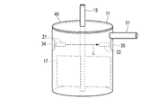
- FIG. 1 is a conceptual diagram showing a configuration example of a slurry ice making machine to which the ice filling rate measuring device of the present embodiment is applied.
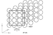
- FIG. 2A is a schematic view illustrating a filling structure of slurry ice particles when IPF is 20%.
- FIG. 2B is a schematic view illustrating a filling structure of the slurry ice particles when the IPF is 30%.
- FIG. 2C is a schematic view illustrating a filling structure of the slurry ice particles when the IPF is 40%.
- FIG. 2D is a schematic view illustrating the filling structure of the slurry ice particles when the IPF is 52%.
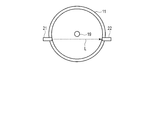
- FIG. 3 is an end view showing the positional relationship between the manufacturing tank, the light source, and the light receiving sensor in FIG.
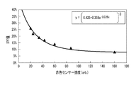
- FIG. 4 is a curve showing an example of the correlation between the sensor intensity and the IPF when a red (660 nm) LED light source is used as a light source and a red LED sensor is used as a light receiving sensor.
- FIG. 5 is a curve showing an example of the correlation between the sensor intensity and the IPF when an infrared (850 nm) LED light source is used as the light source and an infrared LED sensor is used as the light receiving sensor.
- FIG. 6 is a flowchart illustrating an operation example of the ice filling rate measurement device of the present embodiment.
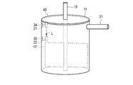
- FIG. 7A is a conceptual diagram illustrating an example of a positional relationship between a manufacturing tank, a light source, and a light receiving sensor according to a first modification.
- FIG. 7A is a conceptual diagram illustrating an example of a positional relationship between a manufacturing tank, a light source, and a light receiving sensor according to a first modification.
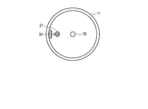
- FIG. 7B is an end view at the height of the light source and the light receiving sensor in FIG. 7A.
- FIG. 8A is a conceptual diagram showing another example of the positional relationship between the manufacturing tank, the light source, and the light receiving sensor in the first modification.
- FIG. 8B is an end view at the height of the light source and the light receiving sensor in FIG. 8A.
- FIG. 9A is a conceptual diagram illustrating an example of a positional relationship between a manufacturing tank, a light source, and a light receiving sensor in Modification Example 2.
- FIG. 9B is an end view at the height of the light source and the light receiving sensor in FIG. 9A.
- FIG. 10A is a conceptual diagram illustrating another example of the positional relationship between the manufacturing tank, the light source, and the light receiving sensor in Modification Example 2.
- FIG. 10B is an end view at the height of the light source and the light receiving sensor in FIG. 10A.
- FIG. 11A is a conceptual diagram illustrating an example of a positional relationship between a manufacturing tank, a light source, and a light receiving sensor according to a third modification.
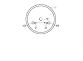
- FIG. 11B is an end view at the height of the light source and the light receiving sensor in FIG. 11A.
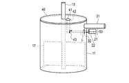
- FIG. 12A is a conceptual diagram illustrating an example of a positional relationship between a manufacturing tank, a light source, and a light receiving sensor in Modification Example 4.
- FIG. 12B is an end view at the height of the light source and the light receiving sensor in FIG. 12A.
- FIG. 1 is a conceptual diagram showing a configuration example of a slurry ice making machine to which the ice filling rate measuring device of the present embodiment is applied.
- the slurry ice making machine 10 aims to produce a slurry ice of about 25% IPF in the manufacturing tank 11 with a precision of about ⁇ 1% in one pass.
- the NaCl tank 12 is a tank for storing an aqueous NaCl solution to be supplied to the manufacturing tank 11.
- a pump 13 for supplying an aqueous solution of NaCl from the NaCl tank 12 to the production tank 11 and a flow meter 14 for measuring the flow rate of the aqueous solution of NaCl supplied by the pump 13 are provided between the NaCl tank 12 and the production tank 11. Is provided.
- the flow rate of the pump 13 is controlled by the control unit 25 based on the measurement result of the flow meter 14 as described later.
- the NaCl aqueous solution supplied to the production tank 11 becomes ice by being cooled by the coolant flowing through the cooling pipe 16 by the condenser 15 and adheres to the inner wall of the production tank 11.
- the stirring blade 17 rotates in the manufacturing tank 11 about the motor shaft 19 by the driving force from the motor 18. Thereby, the stirring blade 17 scrapes off the ice adhered to the inner wall of the production tank 11.
- the scraped ice is mixed with the NaCl solution and coexists, so that slurry ice is generated in the production tank 11.
- a light source 21 and a light receiving sensor 22 are arranged at the same height outside the production tank 11 at a position higher than the upper end of the stirring blade 17.
- the light source 21 and the light receiving sensor 22 constitute an ice filling rate measuring device 20 of the present embodiment together with the ammeter 23, the calculating unit 24, and the control unit 25.
- the ice filling rate measuring device 20 measures the IPF of the slurry ice manufactured in the manufacturing tank 11 as described later.
- the discharge port 31 is provided further above the manufacturing tank 11, that is, at a position higher than the height at which the light source 21 and the light receiving sensor 22 are arranged.
- the upper end opening of the production tank 11 is closed by a lid 40 having a hole through which the motor shaft 19 passes.
- the ice filling rate measuring device 20 obtains a measurement result indicating that the IPF of the slurry ice has become 25% ( ⁇ 1%)
- the slurry ice is discharged from the outlet 31 to the outside of the production tank 11.
- FIGS. 2A to 2D are schematic diagrams illustrating a filling structure of slurry ice particles (hereinafter, also referred to as “ice particles”) for each IPF.
- ice particles slurry ice particles
- FIG. 2A shows the packing structure of ice particles when the IPF is 20%
- FIG. 2B is 30%
- FIG. 2C is 40%
- the diameter of the ice particles is 100 ⁇ m and the ice particles are arranged in a lattice.
- the minimum interparticle distance a is 138 ⁇ m when the IPF is 20%, 120 ⁇ m when the IPF is 30%, and 40 ⁇ m when the IPF is 30%. Is 109 ⁇ m.
- the minimum interparticle distance a becomes 100 ⁇ m, which is equal to the diameter of the ice particles, and the ice particles form a filling structure of a simple cubic lattice.
- the ice filling rate measuring device 20 is a device for measuring the IPF of the slurry ice having such a structure.
- FIG. 3 is an end view showing a positional relationship between the manufacturing tank 11 and the light source 21 and the light receiving sensor 22, and shows an end surface of the manufacturing tank 11 in FIG. 1 at the height of the light source 21 and the light receiving sensor 22.
- FIG. 3 shows only the light source 21 and the light receiving sensor 22 in addition to the manufacturing tank 11 for simplification.
- the light source 21 is, for example, a red LED light source that emits red LED light, an infrared LED light source that emits infrared LED light, or a red laser light source such as a He-Ne laser (633 nm).
- the light receiving sensor 22 uses a red LED sensor, an infrared LED sensor, or a photodiode sensor so as to correspond to the light source. That is, when a red LED light source is used as the light source 21, a red LED sensor is used as the light receiving sensor 22, and when an infrared LED light source is used as the light source 21, an infrared LED sensor is used as the light receiving sensor 22. When a red laser light source is used as the light source 21, a photodiode sensor is used as the light receiving sensor 22.
- the red LED light, the infrared LED light, or the laser light (collectively referred to as “measurement light”) emitted by the light source 21 is manufactured so as to be able to be guided to the inside of the manufacturing tank 11.
- the tank 11 is provided with a transparent window 32 made of glass or plastic.
- the measuring tank 11 is illuminated by the light source 21 and guided to the inside of the manufacturing tank 11, and the measurement light transmitted through the slurry ice in the manufacturing tank 11 can be guided to the outside of the manufacturing tank 11.
- a transparent window 33 made of glass or plastic is provided.
- the light source 21 and the light receiving sensor 22 are arranged outside the manufacturing tank 11 near the transparent window 32 and the transparent window 32, respectively. Then, the measurement light emitted from the light source 21 enters the inside of the manufacturing tank 11 through the transparent window 32 and passes through the slurry ice in the manufacturing tank 11, and then the outside of the manufacturing tank 11 through the transparent window 33. , The light source 21, the transparent window 32, the transparent window 33, and the light receiving sensor 22 are arranged on the same optical path L.
- the optical path L is determined so as to avoid the motor shaft 19.
- the light source 21 and the light receiving sensor 22 are arranged on the same optical path L, the light source 21 and the light receiving sensor 22 do not necessarily need to be arranged outside the manufacturing tank 11, and either the light source 21 or the light receiving sensor 22 or Both may be arranged inside the production tank 11.
- the light source 21 may be arranged outside the manufacturing tank 11 while the light receiving sensor 22 is arranged inside the manufacturing tank 11. In this case, it is not necessary to provide the transparent window 33 in the production tank 11.
- the light receiving sensor 22 may be arranged outside the manufacturing tank 11 while the light source 21 is arranged inside the manufacturing tank 11. In this case, it is not necessary to provide the transparent window 32 in the manufacturing tank 11.
- both the light source 21 and the light receiving sensor 22 may be arranged inside the manufacturing tank 11. In this case, it is not necessary to provide the manufacturing tank 11 with a transparent window.
- the specific configuration will be described in Modifications 1 to 4 described later.
- the light source 21 and the light receiving sensor 22 may be arranged inside the manufacturing tank 11 or may be arranged outside the manufacturing tank 11, but in any case, the light source 21 and the light receiving sensor 22 are detachable, and the slurry ice is removed. It may be arranged only when measuring the IPF, and may not be arranged otherwise.
- the light receiving sensor 22 outputs an electrical characteristic value corresponding to the intensity of the received measurement light.
- a current is assumed as the electrical characteristic value, but a voltage may be used.
- the ammeter 23 measures the current output from the light receiving sensor 22 and outputs the measured current value to the calculation unit 24. This current value corresponds to the intensity of the measurement light.
- the calculation unit 24 stores predetermined correlation information indicating a correlation between the intensity (x) of the measurement light and the IPF (y).
- the correlation information may be a correlation expression such as the following expression (1) or a data table including data indicating the correlation.
- the constants A, B, and C are at least the distance between the light source 21 and the light receiving sensor 22, the light source 21 and the light receiving sensor 22. Is determined individually based on Therefore, it is necessary to determine the values of the constants A, B, and C in advance each time the measurement conditions such as the distance between the light source 21 and the light receiving sensor 22 and the performance of the light source 21 and the light receiving sensor 22 are different.
- the capability of the light source 21 includes, for example, the intensity and wavelength of the measurement light to be radiated, and the capability of the light receiving sensor 22 includes, for example, the reception characteristics of the measurement light.
- the actual measurement conditions (the light source 21 and the light-receiving sensor 22 are compared) with the slurry ice having a known value of IPF (y).
- the light source 21 and the light receiving sensor 22 the light source 21 irradiates measurement light to obtain the intensity (x) received by the light receiving sensor 22. Further, strength (x) is similarly obtained for slurry ice having another IPF (y) value.
- the values of the constants A, B, and C under this measurement condition are determined by obtaining an approximate curve from a plurality of (x, y) sets obtained in this manner.
- the process of determining the values of the constants A, B, and C is performed at an initial setting stage at the time of shipping the ice filling rate measuring device 20 or before the measurement.
- a red LED light source of 660 nm is used as the light source 21
- a red LED sensor is used as the light receiving sensor 22
- the distance between the light source 21 and the light receiving sensor 22 and the capacity of the light source 21 and the light receiving sensor 22 have a certain value.
- the correlation between the sensor intensity and the IPF can be calculated by the equation shown in FIG. follow the curve.
- an infrared LED light source of 850 nm is used as the light source 21
- an infrared LED sensor is used as the light receiving sensor 22
- the distance between the light source 21 and the light receiving sensor 22 and the performance of the light source 21 and the light receiving sensor 22 have a certain value.
- the correlation between the sensor intensity and the IPF is calculated by the equation shown in FIG. follow the curve.
- the unit of the x-axis is an arbitrary unit corresponding to the intensity of the measurement light.
- the arithmetic unit 24 shown in FIG. 1 substitutes the current value output from the ammeter 23 as the intensity (x) into the above equation (1) in which the values of the constants A, B, and C are determined for each measurement condition. Thereby, the IPF (y) is calculated, and the IPF that is the calculation result is output to the control unit 25.
- the calculation unit 24 may obtain the IPF corresponding to the intensity (x) using the above-described data table as an alternative to the expression such as the expression (1).
- the control unit 25 determines the supply flow rate of the aqueous NaCl solution supplied from the NaCl tank 12 to the production tank 11 based on the IPF calculated by the calculation unit 24.
- the control unit 25 sets the supply flow rate higher than the current supply flow rate, and conversely, when the calculated IPF is lower than the target value, The supply flow rate is lower than the supply flow rate. Then, the discharge amount of the pump 13 is controlled so that the NaCl aqueous solution is supplied from the NaCl tank 12 to the production tank 11 according to the supply flow rate.
- the pump 13 supplies the aqueous NaCl solution from the NaCl tank 12 to the production tank 11 at a discharge rate controlled by the control unit 25.
- the flow meter 14 measures the flow rate of the aqueous NaCl solution supplied from the NaCl tank 12 to the production tank 11 and outputs the measurement result to the control unit 25.
- control unit 25 can always grasp the current supply flow rate.
- the IPF of the slurry ice in the production tank 11 is adjusted to the target value, and when it is confirmed that the IPF has reached the target value, the slurry ice is discharged from the outlet 31. It is discharged out of the manufacturing tank 11.
- FIG. 6 is a flowchart showing an operation example of the ice filling rate measuring device of the present embodiment.
- the inside of the production tank 11 is irradiated with measurement light such as LED light or laser light from the light source 21 through the transparent window 32 (S1).
- the light receiving sensor 22 outputs a current corresponding to the intensity of the received measurement light, and the current value is measured by the ammeter 23 (S3).
- the measured current value is output from the ammeter 23 to the calculation unit 24.
- the output current value is used as the intensity (x), an IPF is calculated according to a predetermined correlation formula or data table, and output to the control unit 25 (S4).
- the values of the constants A, B, and C in the correlation equation (1) are individually determined in advance in accordance with the distance between the light source 21 and the light receiving sensor 22 and the measurement conditions such as the capabilities of the light source 21 and the light receiving sensor 22. I have. Therefore, the IPF is calculated with high accuracy by using the correlation equation (1).
- the slurry ice is discharged out of the production tank 11 from the discharge port 31 (S6).
- the control unit 25 supplies the NaCl aqueous solution to be supplied from the NaCl tank 12 to the production tank 11 based on the IPF output from the calculation unit 24.
- the flow rate is determined (S7).
- the controller 25 further determines the discharge amount of the pump 13 so that the aqueous NaCl solution is supplied from the NaCl tank 12 to the production tank 11 according to the determined supply flow rate (S8).
- the flow rate of the NaCl aqueous solution supplied from the NaCl tank 12 to the manufacturing tank 11 is measured by the flow meter 14, and the measurement result is output to the control unit 25. Is grasped.
- the IPF of the slurry ice in the production tank 11 is adjusted to the target value, and the process returns to the step S1. Then, when it is confirmed that the IPF has reached the target value (S5: Yes), the slurry ice is discharged out of the production tank 11 from the discharge port 31 (S6).
- the light source 21 and the light receiving sensor 22 that are small and detachable are used as compared with the ultrasonic measurement method used in the related art. In this way, the measurement can be performed, and the arithmetic control system can be incorporated. Therefore, the IPF can be measured with a compact configuration and with sufficient accuracy.
- FIGS. 7A and 8A are conceptual diagrams illustrating an example of the positional relationship between the manufacturing tank 11, the light source 21, and the light receiving sensor 22 in the first modification.
- the stirring blade 17, the motor shaft 19, the discharge port 31, and the lid 40 are illustrated except for the manufacturing tank 11, the light source 21, and the light receiving sensor 22, and other components are not illustrated. ing.
- the light source 21 and the light receiving sensor 22 are embedded in the wall surface of the manufacturing tank 11 at the same height, which is higher than the upper end of the stirring blade 17 and lower than the lower end of the discharge port 31.
- the light source 21 and the light receiving sensor 22 are joined to the manufacturing tank 11 by welding or the like so that the slurry ice does not leak from the manufacturing tank 11.
- the manufacturing tank 11 is not provided with a transparent window.
- the light source 21 and the light receiving sensor 22 are arranged on the same optical path L so that the measurement light emitted from the light source 21 is received by the light receiving sensor 22.
- the light source 21 and the light receiving sensor 22 are embedded in the wall surface of the manufacturing tank 11 so that the tips of the light source 21 and the light receiving sensor 22 do not project inside the manufacturing tank 11.
- FIG. 7B an end view at the height of the light source 21 and the light receiving sensor 22 in FIG. 7A is as shown in FIG. 7B.
- the light source 21 and the light receiving sensor 22 are embedded inside the wall surface of the manufacturing tank 11 so that the tips of the light source 21 and the light receiving sensor 22 project inside the manufacturing tank 11. .
- FIG. 8B an end view at the height of the light source 21 and the light receiving sensor 22 in FIG. 8A is as shown in FIG. 8B.
- the light source 21 and the light receiving sensor 22 may be housed inside a transparent hermetic cover so that the light source 21 and the light receiving sensor 22 do not come into direct contact with the slurry ice. Accordingly, it is possible to avoid a failure due to the light source 21 coming into direct contact with the slurry ice and a situation in which dew condensation occurs on the light receiving sensor 22 due to the tip of the light receiving sensor 22 coming into contact with the slurry ice, thereby lowering the light receiving sensitivity. be able to.
- ice filling rate measuring device of the first modification by determining the values of the constants A, B, and C in advance, a compact configuration and sufficient accuracy can be obtained as in the above embodiment. IPF can be measured.
- FIGS. 9A and 10A are conceptual diagrams illustrating an example of the positional relationship between the manufacturing tank 11, the light source 21, and the light receiving sensor 22 in Modification 2.
- FIGS. 9A and 10A are conceptual diagrams illustrating an example of the positional relationship between the manufacturing tank 11, the light source 21, and the light receiving sensor 22 in Modification 2.
- illustration of components not related to the description is omitted.
- the light source 21 and the light receiving sensor 22 are arranged inside the manufacturing tank 11. Specifically, the light source 21 and the light-receiving sensor 22 are provided at positions higher than the upper end portion of the stirring blade 17 and lower than the lower end portion of the discharge port 31 inside the production tank 11 by using the fixtures 34 and 35. Is fixed. Further, the light source 21 and the light receiving sensor 22 are arranged on the same optical path L so that the measuring light emitted from the light source 21 passes through the slurry ice in the manufacturing tank 11 and is received by the light receiving sensor 22. The manufacturing tank 11 is not provided with a transparent window. Further, the light source 21 and the light receiving sensor 22 may be housed inside a transparent hermetic cover so that the light source 21 and the light receiving sensor 22 do not directly contact the slurry ice.
- FIG. 9A shows an example in which the light source 21 and the light receiving sensor 22 are arranged at the same height.
- the optical path L is in the horizontal direction.
- FIG. 9B an end view at the height of the light source 21 and the light receiving sensor 22 in FIG. 9A is as shown in FIG. 9B.
- FIG. 10A shows an example in which the light source 21 and the light receiving sensor 22 are vertically arranged.
- the optical path L is in the vertical direction.
- FIG. 10B an end view at the height of the light source 21 in FIG. 10A is as shown in FIG. 10B.
- the light source 21 and the light receiving sensor 22 are not necessarily arranged in the horizontal direction, but may be arranged in the vertical direction. Alternatively, although not shown, the light source 21 and the light receiving sensor 22 may be arranged in an oblique direction.
- the light source 21 and the light receiving sensor 22 are fixed inside the manufacturing tank 11 by the fixing tool 34 and the fixing tool 35, or the fixed light source 21 and the light receiving sensor 22 are fixed.
- the light source 21 and the light-receiving sensor 22 are detachable from the manufacturing tank 11 so that can be removed from the manufacturing tank 11.
- FIG. 11A is a conceptual diagram showing an example of the positional relationship between the manufacturing tank 11, the light source 21, and the light receiving sensor 22 in Modification Example 3.
- FIG. 11A is a conceptual diagram showing an example of the positional relationship between the manufacturing tank 11, the light source 21, and the light receiving sensor 22 in Modification Example 3.
- illustration of components not related to the description is omitted.
- the light source 21 and the light receiving sensor 22 are arranged inside the manufacturing tank 11. Specifically, the supporting portions 42a and 42b are fixed to the lower surface of the lid 40 by the fixing portions 41a and 41b, and the light source 21 is fixed to the supporting portion 42a and the light receiving sensor 22 is fixed to the supporting portion 42b. Further, the light source 21 and the light receiving sensor 22 are arranged on the same optical path L so that the measurement light emitted from the light source 21 is received by the light receiving sensor 22.
- the light source 21 and the light receiving sensor 22 When the upper end opening of the manufacturing tank 11 is closed by the lid 40, the light source 21 and the light receiving sensor 22 have a height higher than the upper end of the stirring blade 17 and lower than the lower end of the outlet 31. To do.
- the manufacturing tank 11 is not provided with a transparent window. Further, the light source 21 and the light receiving sensor 22 may be housed inside a transparent hermetic cover so that the light source 21 and the light receiving sensor 22 do not directly contact the slurry ice.
- FIG. 11A shows an example in which the light source 21 and the light receiving sensor 22 are arranged on the same optical path L at the same height.
- the optical path L is in the horizontal direction.
- FIG. 11B an end view at the height of the light source 21 and the light receiving sensor 22 in FIG. 11A is as shown in FIG. 11B.
- the light source 21 and the light receiving sensor 22 are arranged inside the manufacturing tank 11 at the same time as the upper end opening of the manufacturing tank 11 is closed with the lid 40, and can be measured.
- the light source 21 and the light receiving sensor 22 can be attached and detached extremely easily with a compact configuration. Further, similarly to the above-described embodiment, by determining the values of the constants A, B, and C in advance, it becomes possible to measure the IPF with sufficient accuracy.
- FIG. 12A is a conceptual diagram illustrating an example of a positional relationship between the manufacturing tank 11, the light source 21, and the light receiving sensor 22 in Modification Example 4.
- FIG. 12A illustrates an example of a positional relationship between the manufacturing tank 11, the light source 21, and the light receiving sensor 22 in Modification Example 4.
- illustration of components not related to the description is omitted.
- the storage unit 50 that integrally stores the light source 21 and the light receiving sensor 22 is disposed outside the manufacturing tank 11. Accordingly, one transparent window 32 is provided in the manufacturing tank 11. The height at which the transparent window 32 is provided is higher than the upper end of the stirring blade 17 and lower than the lower end of the outlet 31. Further, the support portion 42 is fixed to the lower surface of the lid 40 by the fixing portion 41, and the mirror 43 is fixed to the support portion 42. The center height of the fixed mirror 43 is the same as the center height of the transparent window 32, and the mirror 43 is arranged so as to face the transparent window 32. As a result, an end view at the height of the mirror 43 and the storage unit 50 in FIG. 12A is as shown in FIG. 12B.
- the mirror 43 functions as a reflection unit that reflects the measurement light emitted by the light source 21 and transmitted through the slurry ice toward the light receiving sensor 22.
- the irradiated measurement light when the light source 21 irradiates measurement light such as LED light or laser light in a state where the upper end opening of the manufacturing tank 11 is closed with the lid 40, the irradiated measurement light is transparent.
- the light enters the inside of the production tank 11 through the window 32, passes through the slurry ice, and reaches the mirror 43. This measurement light is reflected by the mirror 43 and received by the light receiving sensor 22 through the transparent window 32.
- the light source 21 and the light receiving sensor 22 are integrally housed in the housing unit 50, so that the configuration of the entire device can be further compacted.
- only one transparent window 32 provided in the manufacturing tank 11 is required, and the values of the constants A, B, and C are determined in advance in the same manner as in the above-described embodiment while the cost impact is reduced. By doing so, it becomes possible to measure IPF with sufficient accuracy.
- the center height of the fixed mirror 43 is the same as the center height of the transparent window 32, and the optical path L is horizontal.
- the optical path L does not need to be horizontal as long as the optical path from the light source 21 to the mirror 43 and the optical path from the mirror 43 to the light receiving sensor 22 can be set in opposite directions.
- the invention of the present application is not limited to the above-described embodiment, and can be variously modified in an implementation stage without departing from the gist of the invention.
- the embodiments may be implemented in appropriate combinations as much as possible, in which case the combined effects can be obtained.
- the above embodiments include inventions at various stages, and various inventions can be extracted by appropriate combinations of a plurality of disclosed constituent elements.
- the light source 21 and the light receiving sensor 22 can be removably arranged at an arbitrary place.
- LEDs but also infrared rays and laser light can be used as the light sources 21. It is understood that, within the scope of the technical idea invented, various changes and modifications conceivable to those skilled in the art also belong to the technical scope of the present invention.
Landscapes
- Physics & Mathematics (AREA)
- Engineering & Computer Science (AREA)
- Immunology (AREA)
- Pathology (AREA)
- Analytical Chemistry (AREA)
- Biochemistry (AREA)
- General Health & Medical Sciences (AREA)
- General Physics & Mathematics (AREA)
- Life Sciences & Earth Sciences (AREA)
- Chemical & Material Sciences (AREA)
- Health & Medical Sciences (AREA)
- Mechanical Engineering (AREA)
- Thermal Sciences (AREA)
- General Engineering & Computer Science (AREA)
- Measurement Of Levels Of Liquids Or Fluent Solid Materials (AREA)
- Investigating Or Analysing Materials By Optical Means (AREA)
Abstract
スラリーアイスの氷充填率を計測する装置(10)は、スラリーアイスに計測光を照射する光源(21)と、光源によって照射され、スラリーアイスを透過した計測光を受光する受光センサ(22)と、スラリーアイスを透過した計測光の強度と氷充填率との相関関係を示す予め決定された相関関係情報と、受光センサによって受光された計測光の強度とに基づいて、氷充填率を演算する演算部(24)とを備える。
Description
本発明は、スラリーアイスを製造するスラリーアイス製造機と、スラリーアイスの氷充填率(IPF:Ice Packing Factor)を計測する氷充填率計測装置および氷充填率計測方法に関する。
スラリーアイスは、球状の氷と海水や真水や調味液等が混合された液状氷であり、主に、従来の氷では不可能であった生鮮食料品の鮮度保持のために使用されている。
このようなスラリーアイスは、直径約100μmの氷粒子が、希釈海水またはNaCl水溶液などの冷水(例えば、0℃~-6℃)に混在している。その温度は、塩分濃度および、スラリーアイスの氷粒子の直径と、塩水の量の割合で決定され、例えば海水程度の塩分濃度だと、-1.5℃~-3.5℃の間となる。
スラリーアイスは細かくて表面積が大きいという特徴を持つ。そのため、例えば、スラリーアイスを魚の鮮度保持のために使用した場合、魚体の熱をすばやく奪い、同時に浸透圧の差で出血を促し、魚体を絞めた瞬間から雑菌の繁殖による劣化をなくすことが可能である。つまりスラリーアイスを使用することにより、商品価値を高めることができる。また、細かい氷が、微小な隙間にも入り込むため、カニ、ウニ、貝類など冷却が困難な形状を持つ被冷却体にも適用可能である。
また、スラリーアイスは、ブロイラーのボイル後の急速冷却やブロッコリー等の収穫直後の急速冷却にも利用されており、従来の冷蔵庫における乾燥や氷取扱の重労働などの問題の解消にも寄与している。
さらには、スラリーアイスは、緩衝材と冷却材を兼ねた以上の性能を発揮することもできるので、これまで発送自体困難であった殻つきウニや傷つきやすい甘鯛、真ダラ等の輸送も可能となった。
スラリーアイスは、その用途に応じて、適切な氷充填率(以下、「IPF」とも称する)を達成するように生成される。
従って、スラリーアイスのIPFを計測するための計測技術が開発されている。
IPFの計測方法には、非特許文献1,4で開示されているように、静電容量や電気伝導率などの電気特性変化に基づく方法(以下、「第1の方法」と称する)や、非特許文献2で開示されているように、超音波を用い、その減衰率に基づく方法(以下、「第2の方法」と称する)や、非特許文献3で開示されているように、スラリーアイス製造機内の槽の水位から測定される氷量変化に基づく容積法と呼ばれる方法(以下、「第3の方法」と称する)など、様々な方法がある。
(先行技術文献)
(非特許文献1) 勝屋訓他著、「氷水輸送における管内IPF計測装置に関する研究」、空気調和・衛生工学会学術講演会講演集、Vol.1997、No.Pt3、1125~1128頁、(1997)
(非特許文献2) 今井智将他著、「氷水搬送システムに関する基礎的研究(第3報)超音波を用いた管内IPF計測手法の検討」、空気調和・衛生工学会学術講演会講演論文集、Vol.1997、No.Pt3、1117~1120頁、(1997)
(非特許文献3) Jonathan D. WEST et al. “Performance of a Volumetric Method for Measuring State of Charge for Ice Storage System”, ASHRAE Trans (Am Soc Heat Refrig Air Cond Eng), Vol.105, No.Pt2, page 318-324, (1999)
(非特許文献4) 堀部明彦他、「氷水スラリーの種々の氷充填率測定法」、日本機械学会中国四国支部総会・講演会講演論文集、Vol.37、227~228頁、(1999)
(非特許文献1) 勝屋訓他著、「氷水輸送における管内IPF計測装置に関する研究」、空気調和・衛生工学会学術講演会講演集、Vol.1997、No.Pt3、1125~1128頁、(1997)
(非特許文献2) 今井智将他著、「氷水搬送システムに関する基礎的研究(第3報)超音波を用いた管内IPF計測手法の検討」、空気調和・衛生工学会学術講演会講演論文集、Vol.1997、No.Pt3、1117~1120頁、(1997)
(非特許文献3) Jonathan D. WEST et al. “Performance of a Volumetric Method for Measuring State of Charge for Ice Storage System”, ASHRAE Trans (Am Soc Heat Refrig Air Cond Eng), Vol.105, No.Pt2, page 318-324, (1999)
(非特許文献4) 堀部明彦他、「氷水スラリーの種々の氷充填率測定法」、日本機械学会中国四国支部総会・講演会講演論文集、Vol.37、227~228頁、(1999)
しかしながら、上述した第1および第3の方法は、計測精度が低いという問題があり、第2の方法は装置が大掛かりになるという問題がある。
本発明はこのような事情に鑑みてなされたものであり、コンパクトな構成で、かつ、十分な精度でIPFを計測することが可能な氷充填率計測装置および氷充填率計測方法、ならびに、このような氷充填率計測装置を備えたスラリーアイス製造機を提供することを目的とする。
上記の目的を達成するために、本発明では、以下のような手段を講じる。
すなわち、第1の発明は、スラリーアイスの氷充填率を計測する装置であって、スラリーアイスに計測光を照射する光源と、光源によって照射され、スラリーアイスを透過した計測光を受光する受光センサと、スラリーアイスを透過した計測光の強度と氷充填率との相関関係を示す予め決定された相関関係情報と、受光センサによる計測光の受光強度とに基づいて、氷充填率を演算する演算部とを備える。
第2の発明は、第1の発明の氷充填率計測装置において、光源は、赤色LED、赤外光LED、または赤色レーザであり、受光センサを、光源に対応するように、赤色LEDセンサ、赤外光LEDセンサ、またはフォトダイオードセンサとする。
第3の発明は、第1の発明の氷充填率計測装置において、相関関係情報は、相関関係を示す相関式、または、相関関係を示すデータからなるデータテーブルである。
第4の発明は、スラリーアイスを製造する製造機であって、スラリーアイスを製造するための製造槽と、第1の発明の氷充填率計測装置とを備える。
第5の発明は、第4の発明のスラリーアイス製造機において、光源と受光センサを、製造槽の外側に配置し、製造槽に、光源によって照射された計測光を、製造槽の内側へ導くための第1の透明窓と、製造槽内のスラリーアイスを透過した計測光を、製造槽の外側へ導くための第2の透明窓とを設けている。
第6の発明は、第4の発明のスラリーアイス製造機において、光源を、製造槽の外側に配置し、受光センサを、製造槽の内側に配置し、製造槽に、光源によって照射された計測光を、製造槽の内側へ導くための透明窓を設けている。
第7の発明は、第4の発明のスラリーアイス製造機において、光源を、製造槽の内側に配置し、受光センサを、製造槽の外側に配置し、製造槽に、光源によって照射され、製造槽内のスラリーアイスを透過した計測光を、製造槽の外側へ導くための透明窓を設けている。
第8の発明は、第4の発明のスラリーアイス製造機において、光源と、受光センサとを、製造槽の内側に配置している。
第9の発明は、第4の発明のスラリーアイス製造機において、光源と、受光センサとを、一体的に収納する収納ユニットと、光源によって照射され、製造槽内のスラリーアイスを透過した計測光を、受光センサ側に反射させる反射部とをさらに備えている。
第10の発明は、第9の発明のスラリーアイス製造機において、収納ユニットを、製造槽の内側に配置している。
第11の発明は、第9の発明のスラリーアイス製造機において、収納ユニットを、製造槽の外側に配置し、製造槽に、光源によって照射された計測光を、製造槽の内側へ導き、製造槽内のスラリーアイスを透過した計測光を、製造槽の外側へ導くための透明窓を設けている。
第12の発明は、第4の発明のスラリーアイス製造機において、光源および受光センサのうち、少なくとも一方が、着脱可能に配置される。
第13の発明は、第4の発明のスラリーアイス製造機において、製造槽に供給される塩水を貯液した塩水槽をさらに備え、氷充填率計測装置はさらに、演算部によって演算された氷充填率に基づいて、製造槽に供給される塩水の供給流量を決定し、決定された供給流量に基づいて、塩水槽から製造槽への塩水の供給を制御する制御部を備えている。
第14の発明は、スラリーアイスの氷充填率を計測する方法であって、光源から、槽内のスラリーアイスへ計測光を照射し、光源から照射され、槽内のスラリーアイスを透過した計測光を、受光センサによって受光し、スラリーアイスを透過した計測光の強度と氷充填率との相関関係を示す予め決定された相関関係情報と、受光センサによって受光された計測光の強度とに基づいて、氷充填率を演算する。
本発明によれば、コンパクトな構成で、かつ、十分な精度でIPFを計測することができる。
以下に、本発明の実施形態の氷充填率計測装置が適用されたスラリーアイス製造機を、図面を参照して説明する。
(実施形態)
図1は、本実施形態の氷充填率計測装置が適用されたスラリーアイス製造機の構成例を示す概念図である。
図1は、本実施形態の氷充填率計測装置が適用されたスラリーアイス製造機の構成例を示す概念図である。
スラリーアイス製造機10は、製造槽11において、IPF25%前後のスラリーアイスを±1%程度の精度で、ワンパスで生成することを目標としている。
NaCl槽12は、製造槽11に供給するためのNaCl水溶液を貯液する槽である。
NaCl槽12と製造槽11との間には、NaCl槽12から製造槽11へNaCl水溶液を供給するためのポンプ13と、ポンプ13によって供給されるNaCl水溶液の流量を測定するための流量計14が設けられている。ポンプ13の流量は、後述するように流量計14による測定結果に基づいて制御部25によって制御される。
製造槽11に供給されたNaCl水溶液は、凝縮装置15によって冷却パイプ16内を流れる冷却材によって冷却されることによって氷となり、製造槽11の内壁に付着する。
攪拌羽17は、モータ18からの駆動力によって、モータ軸19を中心として、製造槽11内で回転する。これにより攪拌羽17は、製造槽11の内壁に付着した氷を掻き落とす。掻き落とされた氷が、NaCl溶液と混合共存することによって、製造槽11内でスラリーアイスが生成される。
製造槽11の外側には、攪拌羽17の上端部よりも高い位置に、光源21および受光センサ22が同じ高さに配置されている。光源21および受光センサ22は、電流計23、演算部24、および制御部25とともに本実施形態の氷充填率計測装置20を構成する。氷充填率計測装置20は、後述するように、製造槽11において製造されたスラリーアイスのIPFを計測する。
製造槽11のさらに上部、すなわち、光源21および受光センサ22が配置されている高さよりも高い位置に、排出口31が設けられている。スラリーアイスの製造中、製造槽11の上端開口部は、モータ軸19を通すための穴が開けられた蓋40によって塞がれる。
氷充填率計測装置20によって、スラリーアイスのIPFが25%(±1%)になったとの計測結果が得られると、スラリーアイスは、排出口31から製造槽11の外へ排出される。
図2A~図2Dは、スラリーアイス粒子(以降、「氷粒子」とも称する)の充填構造をIPF毎に例示する模式図である。
図2AはIPFが20%、図2Bは同30%、図2Cは同40%、図2Dは同52%である場合における氷粒子の充填構造を示している。
氷粒子の直径は100μmであって、氷粒子が格子配列していると仮定する。この場合、最低粒子間距離aは、図2A~図2Cに図示されるように、IPFが20%である場合には138μm、同30%である場合には120μm、同40%である場合には109μmとなる。さらにIPFが増加し、52%となると、図2Dに図示されるように、最低粒子間距離aは、氷粒子の直径と等しい100μmとなり、氷粒子は、単純立方格子の充填構造を形成する。
氷充填率計測装置20は、このような構造をしたスラリーアイスのIPFを計測するための装置である。
図3は、製造槽11と光源21および受光センサ22との位置関係を示す端面図であり、図1における製造槽11の光源21および受光センサ22の高さにおける端面を示している。図3では簡略のために、製造槽11の他には光源21および受光センサ22しか図示していない。
光源21は、例えば、赤色LED光を照射する赤色LED光源、赤外LED光を照射する赤外光LED光源、または、He-Neレーザ(633nm)のような赤色レーザ光源である。
受光センサ22は、光源に対応するように、赤色LEDセンサ、赤外光LEDセンサ、またはフォトダイオードセンサを使用する。すなわち、光源21として赤色LED光源が使用される場合には、受光センサ22として赤色LEDセンサを使用し、光源21として赤外線LED光源が使用される場合には、受光センサ22として赤外線LEDセンサを使用し、光源21として赤色レーザ光源が使用される場合には、受光センサ22としてフォトダイオードセンサを使用する。
光源21によって照射された赤色LED光、赤外LED光、またはレーザ光(これらを総称して、以下「計測光」と称する)を、製造槽11の内側へ導くことが可能なように、製造槽11にはガラスまたはプラスチック等で構成された透明窓32が設けられている。
また、光源21によって照射され、製造槽11の内側へ導かれ、製造槽11内のスラリーアイスを透過した計測光を、製造槽11の外側へ導くことが可能なように、製造槽11にはガラスまたはプラスチック等で構成された透明窓33が設けられている。
本実施形態では、光源21および受光センサ22は、製造槽11の外側の透明窓32および透明窓32それぞれの近傍に配置される。そして、光源21から照射された計測光が、透明窓32を介して製造槽11の内側へ入射し、製造槽11内のスラリーアイスを透過した後、透明窓33を介して製造槽11の外側の受光センサ22によって受光されるように、光源21、透明窓32、透明窓33、および受光センサ22は、同一光路L上に配置される。
なお、製造槽11の中心には、モータ軸19がある。そのため、光路Lは、モータ軸19を回避するように決定される。
また、光源21と受光センサ22は、同一光路L上に配置されているのであれば、必ずしも製造槽11の外側に配置される必要はなく、光源21と受光センサ22との何れか一方、または両方を、製造槽11の内側に配置しても良い。
例えば、光源21を、製造槽11の外側に配置する一方、受光センサ22を、製造槽11の内側に配置しても良い。この場合、製造槽11に透明窓33を設けることは不要となる。逆に、受光センサ22を、製造槽11の外側に配置する一方、光源21を、製造槽11の内側に配置しても良い。この場合、製造槽11に透明窓32を設けることは不要となる。また、光源21と受光センサ22との両方を製造槽11の内側に配置しても良い。この場合、製造槽11に透明窓を設けることは不要となる。具体的な構成については、後述する変形例1~4で説明する。
このように光源21および受光センサ22は、製造槽11の内側に配置される場合も、製造槽11の外側に配置される場合もあり得るが、何れの場合も着脱可能であり、スラリーアイスのIPFを計測する場合にのみ配置し、そうでない場合には、配置しないようにしても良い。
受光センサ22は、受光した計測光の強度に応じた電気的特性値を出力する。本実施形態では、電気的特性値として電流を想定するが、電圧であっても良い。
電流計23は、受光センサ22から出力された電流を計測し、計測した電流値を演算部24へ出力する。この電流値は、計測光の強度に対応する。
演算部24は、計測光の強度(x)と、IPF(y)との相関関係を示す予め決定された相関関係情報を記憶している。相関関係情報は、以下の(1)式のような相関式であっても、また、相関関係を示すデータからなるデータテーブルであっても良い。
y∝〔A+Bexp(-Cx)〕3 (1)式
上記(1)式において、定数A、B、Cは、少なくとも、光源21と受光センサ22との間の距離と、光源21および受光センサ22の能力とに基づいて個別に決定される。従って、光源21と受光センサ22との間の距離、および、光源21および受光センサ22の能力といった測定条件が異なる毎に、定数A、B、Cの値を予め決定しておく必要がある。
上記(1)式において、定数A、B、Cは、少なくとも、光源21と受光センサ22との間の距離と、光源21および受光センサ22の能力とに基づいて個別に決定される。従って、光源21と受光センサ22との間の距離、および、光源21および受光センサ22の能力といった測定条件が異なる毎に、定数A、B、Cの値を予め決定しておく必要がある。
なお、光源21の能力とは、例えば、照射する計測光の強度や波長等を含み、受光センサ22の能力とは、例えば計測光の受信特性等を含む。
具体的な定数A、B、Cの値を予め決定しておくために、例えば、IPF(y)の値が既知であるスラリーアイスに対して、実際の測定条件(光源21と受光センサ22との間の距離、光源21および受光センサ22の能力)において、光源21から、計測光を照射し、受光センサ22によって受光された強度(x)を得る。さらに、別のIPF(y)の値を有するスラリーアイスに対しても、同様にして強度(x)を得る。このようにして得られる複数の(x、y)の組から、近似曲線を求めることによって、この測定条件における定数A、B、Cの値を決定する。このような定数A、B、Cの値を決定する工程は、氷充填率計測装置20の出荷時の初期設定段階、あるいは、計測前に実行しておく。
例えば、光源21として660nmの赤色LED光源が使用され、受光センサ22として赤色LEDセンサが使用され、光源21と受光センサ22との間の距離と、光源21および受光センサ22の能力とがある値に規定された測定条件では、定数A=0.425、B=0.358、C=0.026となり、この場合、センサ強度とIPFとの相関関係は、図4に示されるような式および曲線に従う。
また、光源21として850nmの赤外線LED光源が使用され、受光センサ22として赤外線LEDセンサが使用され、光源21と受光センサ22との間の距離と、光源21および受光センサ22の能力とがある値に規定された測定条件では、定数A=0.425、B=0.753、C=0.028となり、この場合、センサ強度とIPFとの相関関係は、図5に示されるような式および曲線に従う。
なお、図4、図5ともに、x軸の単位は、計測光の強度に対応する任意の単位としている。
図1に示す演算部24は、電流計23から出力された電流値を強度(x)として、測定条件毎に定数A、B、Cの値が決定されている上記(1)式に代入することにより、IPF(y)を演算し、演算結果であるIPFを、制御部25へ出力する。演算部24は、上記(1)式のような式の代替として、上述したデータテーブルを用いて、強度(x)に対応するIPFを求めても良い。
制御部25は、演算部24によって演算されたIPFに基づいて、NaCl槽12から製造槽11へ供給されるNaCl水溶液の供給流量を決定する。制御部25は、演算されたIPFが、目標値(例えば、25%)よりも高いのであれば、現在の供給流量よりも高い供給流量とし、逆に目標値よりも低いのであれば、現在の供給流量よりも低い供給流量とする。そして、供給流量に従ってNaCl槽12から製造槽11へNaCl水溶液が供給されるようにポンプ13の吐出量を制御する。
ポンプ13は、制御部25によって制御された吐出量で、NaCl槽12から製造槽11へNaCl水溶液を供給する。
流量計14は、NaCl槽12から製造槽11へ供給されるNaCl水溶液の流量を測定し、測定結果を、制御部25へ出力する。
これによって、制御部25は、常に、現在の供給流量を把握することができる。
このようなNaCl水溶液の流量制御の結果、製造槽11内のスラリーアイスのIPFが目標値になるように調整され、目標値になったことが確認されると、スラリーアイスが、排出口31から製造槽11の外へ排出される。
次に、以上のように構成した本実施形態の氷充填率計測装置20の動作について説明する。
図6は、本実施形態の氷充填率計測装置の動作例を示すフローチャートである。
製造槽11の内部では、スラリーアイスが製造されている。
スラリーアイスのIPFを計測するために、光源21から、透明窓32を介して、製造槽11の内側へLED光やレーザ光である計測光が照射される(S1)。
製造槽11の内側へ導かれた計測光は、製造槽11内のスラリーアイスを透過し、透明窓33を介して受光センサ22によって受光される(S2)。
受光センサ22では、受光した計測光の強度に応じた電流が出力され、電流値が、電流計23によって計測される(S3)。
計測された電流値は、電流計23から演算部24へ出力される。演算部24では、出力された電流値が、強度(x)として用いられ、予め決定された相関式またはデータテーブルに従ってIPFが演算され、制御部25へ出力される(S4)。
相関式(1)における定数A、B、Cの値は、光源21と受光センサ22との間の距離、および、光源21および受光センサ22の能力といった測定条件に応じて個別に予め決定されている。従って、相関式(1)を用いることによって、高い精度でIPFが演算される。
演算されたIPFが目標値であれば(S5:Yes)、スラリーアイスが、排出口31から製造槽11の外へ排出される(S6)。
一方、演算されたIPFが目標値でなければ(S5:No)、演算部24から出力されたIPFに基づいて、制御部25において、NaCl槽12から製造槽11へ供給されるNaCl水溶液の供給流量が決定される(S7)。
制御部25ではさらに、決定された供給流量に従ってNaCl水溶液がNaCl槽12から製造槽11へ供給されるように、ポンプ13の吐出量が決定される(S8)。
この吐出量でポンプ13が動作することによって、NaCl槽12から製造槽11へのNaCl水溶液の供給量が制御される(S9)。
なお、NaCl槽12から製造槽11へ供給されるNaCl水溶液の流量は、流量計14によって測定され、測定結果が、制御部25へ出力され、これによって、制御部25によって、常に現在の供給流量が把握される。
このようなNaCl水溶液の流量制御によって、製造槽11内のスラリーアイスのIPFが目標値になるように調整され、ステップS1の処理へ戻る。そして、IPFが目標値になったことが確認される(S5:Yes)と、スラリーアイスが、排出口31から製造槽11の外へ排出される(S6)。
上述したように、本実施形態の氷充填率計測装置20によれば、例えば、従来技術で使用されている超音波測定法等に比べ、小型でかつ着脱可能な光源21および受光センサ22を用いることによって測定が可能であり、しかも、演算制御系も組み込み可能であることから、コンパクトな構成で、かつ、十分な精度でIPFを計測することが可能となる。
(変形例1)
氷充填率計測装置20の変形例1について説明する。
氷充填率計測装置20の変形例1について説明する。
変形例1では、上述した実施形態と異なる点について説明する。
図7Aおよび図8Aは、変形例1における製造槽11と光源21および受光センサ22との位置関係の例を示す概念図である。簡略のために、製造槽11、光源21、および受光センサ22以外では、攪拌羽17、モータ軸19、排出口31、および蓋40のみを図示しており、その他の構成要素の図示は省略している。
変形例1では、攪拌羽17の上端部よりも高く、排出口31の下端部よりも低い、同じ高さにおいて、製造槽11の壁面内部に光源21および受光センサ22を埋め込んでいる。この場合、光源21および受光センサ22は、製造槽11からスラリーアイスが漏出しないように、製造槽11に溶接等により接合される。製造槽11には、透明窓は設けられない。また、光源21から照射された計測光が受光センサ22によって受光されるように、光源21と受光センサ22とを、同一光路L上に配置する。
図7Aに示す例では、光源21および受光センサ22の先端が、製造槽11の内側に突出しないように、光源21および受光センサ22が、製造槽11の壁面の内部に埋め込まれている。
その結果、図7Aにおける光源21および受光センサ22の高さにおける端面図は、図7Bに示す通りとなる。
一方、図8Aに示す例では、光源21および受光センサ22の先端が、製造槽11の内側に突出するように、光源21および受光センサ22が、製造槽11の壁面の内部に埋め込まれている。
その結果、図8Aにおける光源21および受光センサ22の高さにおける端面図は、図8Bに示す通りとなる。なお、光源21および受光センサ22がスラリーアイスと直接接触しないように、光源21および受光センサ22を、透明な密閉カバーの内部に収納しても良い。これによって、光源21がスラリーアイスと直接接触することによる故障や、受光センサ22の先端が、スラリーアイスと接触することによって、受光センサ22に結露が発生し、受光感度が低下することを回避することができる。
このような変形例1の氷充填率計測装置によっても、定数A、B、Cの値をあらかじめ決定しておくことによって、上記実施形態と同様に、コンパクトな構成で、かつ、十分な精度でIPFを計測することが可能となる。
(変形例2)
氷充填率計測装置20の変形例2について説明する。
氷充填率計測装置20の変形例2について説明する。
変形例2でもまた、上述した実施形態と異なる点について説明する。
図9Aおよび図10Aは、変形例2における製造槽11と光源21および受光センサ22との位置関係の例を示す概念図である。ここでも、簡略のために、説明に関係のない構成要素の図示を省略している。
変形例2では、製造槽11の内側に光源21および受光センサ22を配置する。具体的には、製造槽11の内部の攪拌羽17の上端部よりも高く、排出口31の下端部よりも低い場所に、固定具34および固定具35を用いて、光源21および受光センサ22を固定する。また、光源21から照射された計測光が、製造槽11内のスラリーアイスを透過した後、受光センサ22によって受光されるように、光源21と受光センサ22とを同一光路L上に配置する。製造槽11に、透明窓は設けられない。また、光源21および受光センサ22がスラリーアイスと直接接触しないように、光源21および受光センサ22を透明な密閉カバーの内部に収納するようにしても良い。
図9Aは、光源21と受光センサ22とが同じ高さに配置された例を示している。この場合、光路Lは水平方向となる。
その結果、図9Aにおける光源21および受光センサ22の高さにおける端面図は、図9Bに示す通りとなる。
一方、図10Aは、光源21と受光センサ22とが上下に配置された例を示している。この場合、光路Lは上下方向となる。
その結果、図10Aにおける光源21の高さにおける端面図は、図10Bに示す通りとなる。
このように、光源21と受光センサ22は必ずしも水平方向に配置される必要はなく、上下方向に配置されても良い。あるいは、図示していないが、光源21と受光センサ22とが斜め方向に配置されても良い。
図9および図10のいずれの場合であっても、固定具34および固定具35によって、光源21および受光センサ22を製造槽11の内側に固定したり、固定されている光源21および受光センサ22を製造槽11から取り外すことができるように、光源21および受光センサ22は、製造槽11に対して着脱可能となっている。
このような変形例2の氷充填率計測装置であっても、定数A、B、Cの値を予め決定しておくことによって、上記実施形態と同様に、コンパクトな構成で、かつ、十分な精度でIPFを計測することが可能となる。
(変形例3)
氷充填率計測装置20の変形例3について説明する。
氷充填率計測装置20の変形例3について説明する。
変形例3でもまた、上述した実施形態と異なる点について説明する。
図11Aは、変形例3における製造槽11と光源21および受光センサ22との位置関係の例を示す概念図である。ここでも、簡略のために、説明に関係のない構成要素の図示を省略している。
変形例3でも、製造槽11の内側に、光源21および受光センサ22を配置する。具体的には、固定部41a、41bによって、蓋40の下面に支持部42a、42bを固定し、さらに、支持部42aに光源21を、支持部42bに受光センサ22を固定する。また、光源21から照射された計測光が、受光センサ22によって受光されるように、光源21と受光センサ22とを同一光路L上に配置する。
また、製造槽11の上端開口部が蓋40によって塞がれた場合、光源21および受光センサ22が、攪拌羽17の上端部よりも高く、排出口31の下端部よりも低い高さになるようにする。製造槽11には、透明窓は設けられない。また、光源21および受光センサ22がスラリーアイスと直接接触しないように、光源21および受光センサ22を透明な密閉カバーの内部に収納するようにしても良い。
図11Aは、光源21と受光センサ22とが、同じ高さにおいて、同一光路L上に配置された例を示している。この場合、光路Lは、水平方向となる。
その結果、図11Aにおける光源21および受光センサ22の高さにおける端面図は、図11Bに示す通りとなる。
このような構成とすれば、製造槽11の上端開口部を蓋40で塞ぐことと同時に、光源21および受光センサ22も、製造槽11の内側に配置され、計測可能な状態となる。
そして、製造槽11の上端開口部から蓋40を取り外すことと同時に、光源21および受光センサ22の製造槽11からの取り外しもなされる。
このように、変形例3の氷充填率計測装置によれば、コンパクトな構成で、光源21および受光センサ22の着脱を極めて容易に行うことが可能となる。さらに、前述した実施形態と同様に、定数A、B、Cの値を予め決定しておくことによって、十分な精度でIPFを計測することが可能となる。
(変形例4)
氷充填率計測装置20の変形例4について説明する。
氷充填率計測装置20の変形例4について説明する。
変形例4でも、上述した実施形態と異なる点について説明する。
図12Aは、変形例4における製造槽11と光源21および受光センサ22との位置関係の例を示す概念図である。ここでも、簡略のために、説明に関係のない構成要素の図示を省略している。
変形例4では、光源21および受光センサ22を一体的に収納した収納ユニット50を、製造槽11の外側に配置する。これに伴い、製造槽11に、1つの透明窓32を設けている。透明窓32が設けられる高さは、攪拌羽17の上端部よりも高く、排出口31の下端部よりも低い位置とする。さらに、蓋40の下面に、固定部41によって支持部42を固定し、支持部42にミラー43を固定する。固定されたミラー43の中心高さは、透明窓32の中心高さと同じになるようにし、透明窓32と対向するようにミラー43を配置する。その結果、図12Aにおけるミラー43および収納ユニット50の高さにおける端面図は、図12Bに示す通りとなる。
このように、ミラー43は、光源21によって照射され、スラリーアイスを透過した計測光を、受光センサ22に向けて反射させる反射部として機能する。
このような構成によれば、製造槽11の上端開口部を蓋40で塞いだ状態で、光源21が、LED光やレーザ光のような計測光を照射すると、照射された計測光は、透明窓32を介して製造槽11の内側に入射し、スラリーアイスを透過した後、ミラー43に到達する。この計測光は、ミラー43によって反射され、透明窓32を介して受光センサ22によって受光される。
このように、変形例4の氷充填率計測装置によれば、光源21と受光センサ22とが、収納ユニット50内に一体的に収納されているので、装置全体の構成をさらにコンパクトすることができるのみならず、製造槽11に設けられる透明窓32も1つだけでよく、コスト的なインパクトも少なく抑えながら、前述した実施形態と同様に、定数A、B、Cの値を予め決定しておくことによって、十分な精度でIPFを計測することが可能となる。
なお、上記説明では、固定されたミラー43の中心高さが、透明窓32の中心高さと同じであり、光路Lが水平になる例であるが、ミラー43の傾斜角度を調節することによって、光源21からミラー43までの光路と、ミラー43から受光センサ22までの光路とを反対方向にすることができるのであれば、光路Lは水平に限定される必要はない。
また、図示は省略するが、当業者であれば、収納ユニット50を、製造槽11の内側に配置することによって、透明窓32を不要とした構成でも、同様な効果を奏することができることも容易に想到できるであろう。
なお、本願発明は、上記実施形態に限定されるものではなく、実施段階ではその要旨を逸脱しない範囲で種々に変形することが可能である。また、各実施形態は可能な限り適宜組み合わせて実施してもよく、その場合組み合わせた効果が得られる。更に、上記実施形態には種々の段階の発明が含まれており、開示される複数の構成要件における適当な組み合わせにより種々の発明が抽出され得る。
例えば、光源21および受光センサ22を任意の場所に着脱可能に配置することができ、さらには、光源21として、LEDのみならず、赤外線やレーザ光を用いることができるなど、特許請求の範囲の発明された技術的思想の範疇において、当業者であれば想到し得る各種の変更例及び修正例についても本発明の技術的範囲に属するものと了解される。
Claims (14)
- スラリーアイスの氷充填率を計測する装置であって、
前記スラリーアイスに計測光を照射する光源と、
前記光源によって照射され、前記スラリーアイスを透過した前記計測光を受光する受光センサと、
前記スラリーアイスを透過した前記計測光の強度と前記氷充填率との相関関係を示す予め決定された相関関係情報と、前記受光センサによって受光された計測光の強度とに基づいて、前記氷充填率を演算する演算部と、
を備えた氷充填率計測装置。 - 前記光源は、赤色LED、赤外光LED、または赤色レーザであり、
前記受光センサを、前記光源に対応するように、赤色LEDセンサ、赤外光LEDセンサ、またはフォトダイオードセンサとした、請求項1に記載の氷充填率計測装置。 - 前記相関関係情報は、前記相関関係を示す相関式、または、前記相関関係を示すデータからなるデータテーブルである、請求項1に記載の氷充填率計測装置。
- スラリーアイスを製造する製造機であって、
前記スラリーアイスを製造するための製造槽と、
請求項1に記載の氷充填率計測装置と、
を備えたスラリーアイス製造機。 - 前記光源と前記受光センサを、前記製造槽の外側に配置し、
前記製造槽に、前記光源によって照射された前記計測光を、前記製造槽の内側へ導くための第1の透明窓と、前記製造槽内のスラリーアイスを透過した前記計測光を、前記製造槽の外側へ導くための第2の透明窓とを設けた、請求項4に記載のスラリーアイス製造機。 - 前記光源を、前記製造槽の外側に配置し、前記受光センサを、前記製造槽の内側に配置し、
前記製造槽に、前記光源によって照射された前記計測光を、前記製造槽の内側へ導くための透明窓を設けた、請求項4に記載のスラリーアイス製造機。 - 前記光源を、前記製造槽の内側に配置し、前記受光センサを、前記製造槽の外側に配置し、
前記製造槽に、前記光源によって照射され、前記製造槽内のスラリーアイスを透過した前記計測光を、前記製造槽の外側へ導くための透明窓を設けた、請求項4に記載のスラリーアイス製造機。 - 前記光源と、前記受光センサとを、前記製造槽の内側に配置した、請求項4に記載のスラリーアイス製造機。
- 前記光源と、前記受光センサとを、一体的に収納する収納ユニットと、
前記光源によって照射され、前記製造槽内のスラリーアイスを透過した前記計測光を、前記受光センサ側に反射させる反射部と、
をさらに備えた請求項4に記載のスラリーアイス製造機。 - 前記収納ユニットを、前記製造槽の内側に配置した、請求項9に記載のスラリーアイス製造機。
- 前記収納ユニットを、前記製造槽の外側に配置し、
前記製造槽に、前記光源によって照射された前記計測光を、前記製造槽の内側へ導き、前記製造槽内のスラリーアイスを透過した前記計測光を、前記製造槽の外側へ導くための透明窓を設けた、請求項9に記載のスラリーアイス製造機。 - 前記光源および前記受光センサのうち、少なくとも一方が、着脱可能に配置される、請求項4に記載のスラリーアイス製造機。
- 前記製造槽に供給される塩水を貯液した塩水槽をさらに備え、
前記氷充填率計測装置はさらに、前記演算部によって演算された氷充填率に基づいて、前記製造槽に供給される塩水の供給流量を決定し、決定された供給流量に基づいて、前記塩水槽から前記製造槽への塩水の供給を制御する制御部を備えた、請求項4に記載のスラリーアイス製造機。 - スラリーアイスの氷充填率を計測する方法であって、
光源から、槽内のスラリーアイスへ計測光を照射し、
前記光源から照射され、前記槽内のスラリーアイスを透過した前記計測光を、受光センサによって受光し、
前記スラリーアイスを透過した前記計測光の強度と前記氷充填率との相関関係を示す予め決定された相関関係情報と、前記受光センサによって受光された計測光の強度とに基づいて、前記氷充填率を演算する、氷充填率計測方法。
Applications Claiming Priority (2)
| Application Number | Priority Date | Filing Date | Title |
|---|---|---|---|
| JP2018-160586 | 2018-08-29 | ||
| JP2018160586A JP2020034394A (ja) | 2018-08-29 | 2018-08-29 | 氷充填率計測装置、氷充填率計測方法、およびスラリーアイス製造機 |
Publications (1)
| Publication Number | Publication Date |
|---|---|
| WO2020045583A1 true WO2020045583A1 (ja) | 2020-03-05 |
Family
ID=69644493
Family Applications (1)
| Application Number | Title | Priority Date | Filing Date |
|---|---|---|---|
| PCT/JP2019/033978 Ceased WO2020045583A1 (ja) | 2018-08-29 | 2019-08-29 | 氷充填率計測装置、氷充填率計測方法、およびスラリーアイス製造機 |
Country Status (2)
| Country | Link |
|---|---|
| JP (1) | JP2020034394A (ja) |
| WO (1) | WO2020045583A1 (ja) |
Citations (8)
| Publication number | Priority date | Publication date | Assignee | Title |
|---|---|---|---|---|
| JPH037869A (ja) * | 1989-06-05 | 1991-01-16 | Sanyo Electric Co Ltd | 製氷機の貯氷量検出装置 |
| JPH09318103A (ja) * | 1996-05-28 | 1997-12-12 | Sanki Eng Co Ltd | 氷蓄熱装置 |
| JPH10325658A (ja) * | 1997-05-28 | 1998-12-08 | Takenaka Komuten Co Ltd | 氷蓄熱装置および氷含有液体の供給方法 |
| JP2009121766A (ja) * | 2007-11-15 | 2009-06-04 | Mayekawa Mfg Co Ltd | 氷スラリー充填方法及び装置 |
| JP2010169322A (ja) * | 2009-01-23 | 2010-08-05 | Mitsubishi Electric Corp | シャーベット氷製造システム、シャーベット氷の氷量測定装置及びシャーベット氷の氷量測定方法 |
| JP2011033279A (ja) * | 2009-08-03 | 2011-02-17 | Tokyo Denki Univ | 氷蓄熱装置 |
| JP2018077043A (ja) * | 2018-01-09 | 2018-05-17 | 高砂熱学工業株式会社 | 貯氷タンク |
| JP2018124057A (ja) * | 2018-04-16 | 2018-08-09 | 高知県公立大学法人 | 魚介類用スラリーアイス生産方法 |
-
2018
- 2018-08-29 JP JP2018160586A patent/JP2020034394A/ja active Pending
-
2019
- 2019-08-29 WO PCT/JP2019/033978 patent/WO2020045583A1/ja not_active Ceased
Patent Citations (8)
| Publication number | Priority date | Publication date | Assignee | Title |
|---|---|---|---|---|
| JPH037869A (ja) * | 1989-06-05 | 1991-01-16 | Sanyo Electric Co Ltd | 製氷機の貯氷量検出装置 |
| JPH09318103A (ja) * | 1996-05-28 | 1997-12-12 | Sanki Eng Co Ltd | 氷蓄熱装置 |
| JPH10325658A (ja) * | 1997-05-28 | 1998-12-08 | Takenaka Komuten Co Ltd | 氷蓄熱装置および氷含有液体の供給方法 |
| JP2009121766A (ja) * | 2007-11-15 | 2009-06-04 | Mayekawa Mfg Co Ltd | 氷スラリー充填方法及び装置 |
| JP2010169322A (ja) * | 2009-01-23 | 2010-08-05 | Mitsubishi Electric Corp | シャーベット氷製造システム、シャーベット氷の氷量測定装置及びシャーベット氷の氷量測定方法 |
| JP2011033279A (ja) * | 2009-08-03 | 2011-02-17 | Tokyo Denki Univ | 氷蓄熱装置 |
| JP2018077043A (ja) * | 2018-01-09 | 2018-05-17 | 高砂熱学工業株式会社 | 貯氷タンク |
| JP2018124057A (ja) * | 2018-04-16 | 2018-08-09 | 高知県公立大学法人 | 魚介類用スラリーアイス生産方法 |
Also Published As
| Publication number | Publication date |
|---|---|
| JP2020034394A (ja) | 2020-03-05 |
Similar Documents
| Publication | Publication Date | Title |
|---|---|---|
| EP3008506B1 (en) | Molecular manipulation system and method | |
| US20150362426A1 (en) | Dryness fraction distribution measuring device and dryness fraction distribution measuring method | |
| CN107003231B (zh) | 散射式浊度计和控制该浊度计中的通风空气的湿度的方法 | |
| JP5885461B2 (ja) | 乾き度測定装置及び乾き度測定方法 | |
| CN113720783B (zh) | 一种气/液体光谱偏振二向反射模型特性测试装置及方法 | |
| CN105395167B (zh) | 被检体信息获取装置 | |
| FI122997B (fi) | Menetelmä ja sovitelma optisesti epähomogeenisen aineen virtausnopeuden mittaamiseksi | |
| BR102016025452B1 (pt) | sistema ultrassônico, sistema de ensaio ultrassônico, e, método para ensaio não destrutivo | |
| CN105547656B (zh) | 一种在线实时测量激光晶体热透镜焦距的方法与装置 | |
| CN113551787B (zh) | 一种用于评估大气对主动遥感探测方式影响的模拟装置 | |
| CN109164129A (zh) | 一种测定相变动力系统体积变化率的装置及方法 | |
| JP6633685B2 (ja) | 高度光学干渉顕微鏡法を採用した光学積層装置 | |
| JP2010169322A (ja) | シャーベット氷製造システム、シャーベット氷の氷量測定装置及びシャーベット氷の氷量測定方法 | |
| JP2017051149A (ja) | 液中生物粒子の検出装置、及び液中生物粒子の検出方法 | |
| JP2020034394A (ja) | 氷充填率計測装置、氷充填率計測方法、およびスラリーアイス製造機 | |
| JP2020125943A (ja) | 薄層の液膜における液膜破断割合測定方法 | |
| Hammond et al. | Direct measurement of the ballistic motion of a freely floating colloid in Newtonian and viscoelastic fluids | |
| Corato et al. | High-energy-density acoustofluidic device using a double-parabolic ultrasonic transducer | |
| CN103401129A (zh) | 一种LD泵浦的单纵模连续波1645nm固体激光装置 | |
| CN107271035B (zh) | 一种激光器的功率检测装置 | |
| CN205562341U (zh) | 气溶胶实时监测仪 | |
| CN107561044A (zh) | 两相管道视窗、测量系统、视图获取方法、三维重构方法及空泡率测量 | |
| CN115463816B (zh) | 一种光纤超声发射装置及制备方法 | |
| US20100133447A1 (en) | Acousto-Optical Test and Analysis Cavitation Chamber | |
| JP6006605B2 (ja) | 蒸気流量測定装置および蒸気流量測定方法 |
Legal Events
| Date | Code | Title | Description |
|---|---|---|---|
| 121 | Ep: the epo has been informed by wipo that ep was designated in this application |
Ref document number: 19855888 Country of ref document: EP Kind code of ref document: A1 |
|
| NENP | Non-entry into the national phase |
Ref country code: DE |
|
| 122 | Ep: pct application non-entry in european phase |
Ref document number: 19855888 Country of ref document: EP Kind code of ref document: A1 |