WO2020045331A1 - ストロークセンサ - Google Patents
ストロークセンサ Download PDFInfo
- Publication number
- WO2020045331A1 WO2020045331A1 PCT/JP2019/033227 JP2019033227W WO2020045331A1 WO 2020045331 A1 WO2020045331 A1 WO 2020045331A1 JP 2019033227 W JP2019033227 W JP 2019033227W WO 2020045331 A1 WO2020045331 A1 WO 2020045331A1
- Authority
- WO
- WIPO (PCT)
- Prior art keywords
- contact
- shaft
- positive
- housing
- negative
- Prior art date
- Legal status (The legal status is an assumption and is not a legal conclusion. Google has not performed a legal analysis and makes no representation as to the accuracy of the status listed.)
- Ceased
Links
Images



Classifications
-
- G—PHYSICS
- G01—MEASURING; TESTING
- G01B—MEASURING LENGTH, THICKNESS OR SIMILAR LINEAR DIMENSIONS; MEASURING ANGLES; MEASURING AREAS; MEASURING IRREGULARITIES OF SURFACES OR CONTOURS
- G01B7/00—Measuring arrangements characterised by the use of electric or magnetic techniques
-
- H—ELECTRICITY
- H01—ELECTRIC ELEMENTS
- H01H—ELECTRIC SWITCHES; RELAYS; SELECTORS; EMERGENCY PROTECTIVE DEVICES
- H01H13/00—Switches having rectilinearly-movable operating part or parts adapted for pushing or pulling in one direction only, e.g. push-button switch
- H01H13/02—Details
- H01H13/12—Movable parts; Contacts mounted thereon
- H01H13/14—Operating parts, e.g. push-button
- H01H13/16—Operating parts, e.g. push-button adapted for operation by a part of the human body other than the hand, e.g. by foot
Definitions
- the present invention relates to a stroke sensor used for a quick shifter or the like of a motorcycle.
- the stroke sensor used for a quick shifter or the like of a motorcycle, there is one described in, for example, Patent Document 1.
- the stroke sensor is directly or indirectly connected to an object to be detected, which is a movable component (such as a shift pedal of a transmission of a motorcycle) mounted on a vehicle.
- a part of the shaft 1 that reciprocates in accordance with the operation described above is generally housed in a housing space 5 formed inside a housing 4 including a first case 2 and a second case 3.
- an origin return means 8 including pistons 6, 6 and a spring 7 is provided, and the shaft 1 is provided with a magnet having two poles magnetized in the axial direction of the shaft 1.
- the housing 4 is provided with a magnetic detection element 10 on a substrate 11 so as to face the magnet 9.
- the magnetic detection element 10 detects a change in the direction of the magnetic field by the magnet 9, and the detection result is transmitted to the cord ( The operation (displacement) of the object to be detected is detected by the cable 12.
- the detected object is a shift pedal of a transmission, which is operated by a shift-up operation. If it is only necessary to detect the operation due to the fact, the detection accuracy up to that point is not necessarily required.
- components such as a magnet and a Hall element constituting a magnetic detecting element are costly for high-precision detection, and materials of components such as a shaft and a spring are non-magnetic. There is a problem that the material is restricted by the material and the soft magnetic material.
- the present invention has been made in view of the above circumstances, and it is an object of the present invention to provide a stroke sensor capable of reducing costs and relaxing restrictions on the material of components.
- a stroke sensor includes a housing, and a conductive shaft that is at least partially housed inside the housing, and that reciprocates in a forward direction and a reverse direction in accordance with the operation of a detection target. And, provided with a positive or negative potential provided in the housing, a contact that comes into contact with the shaft when the shaft moves in the forward direction, electricity is supplied by the contact between the shaft and the contact, The operation of the object to be detected is detected.
- the housing includes a positive contact provided with a positive potential as the contact, and a negative contact that contacts the shaft when the shaft moves in the forward direction in opposition to the positive contact;
- a connector to which a code assembly including a positive wiring and a negative wiring is connected is provided, and by connecting the code assembly to the connector, the positive wiring is connected to the positive contact, and a positive potential is applied.
- the negative wiring is connected to the negative contact, and in this state, by the contact between the shaft, the positive contact and the negative contact, electricity is supplied from the positive contact to the shaft and the negative contact, and the object to be detected is May be detected.
- the housing is provided with a housing body accommodating at least a part of the shaft therein and the connector, and the positive electrode contact and the negative electrode contact are attached thereto, and the orientation of the connector with respect to the housing body is changed.
- the positive electrode contact and the negative electrode contact may be attachable such that the case and the case of the second orientation are the same or interchanged.
- the housing has conductivity, and the housing is provided with a positive electrode contact to which a positive potential is applied as the contact, and the shaft and the negative electrode terminal are provided without being insulated from the housing; A positive wire is connected to the contact to apply a positive potential, and a negative wire is connected to the negative terminal.
- the shaft contacts the shaft and the housing.
- the operation of the detected object may be detected by energizing the negative electrode terminal.
- the cost can be reduced and the restrictions on the material of the parts can be reduced.
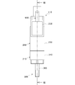
- FIG. 2 is an explanatory diagram showing a stroke sensor according to the first embodiment.
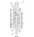
- FIG. 2 is a cross-sectional view of the stroke sensor of FIG. 1 taken along the line II-II.
- FIG. 3 is a cross-sectional view of the stroke sensor of FIG. 1 taken along the line III-III (FIG. 2).
- FIG. 2 is an explanatory diagram showing a connector assembly of the stroke sensor of FIG. 1.
- FIG. 5 is an explanatory diagram showing an aspect in which the connector assembly of FIG. 4 is attached to a housing body.
- FIG. 5 is an explanatory diagram showing an aspect in which the direction of the connector of the connector assembly of FIG. 4 is changed.
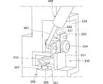
- FIG. 9 is an explanatory diagram illustrating a stroke sensor according to a second embodiment.
- FIG. 8 is a cross-sectional view of the stroke sensor of FIG. 7 taken along line VIII-VIII.
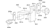
- FIG. 8 is an explanatory diagram showing an aspect in which the contact assembly of the stroke sensor of FIG. 7 is attached to a housing body. It is explanatory drawing which shows the contact assembly of FIG. It is an explanatory view showing a conventional stroke sensor.
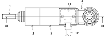
- FIG. 12 is a cross-sectional view of the stroke sensor of FIG. 11 taken along the line XII-XII.
- the stroke sensor according to the present embodiment is used for a quick shifter or the like of a motorcycle, and detects a movable portion of a movable component (a shift pedal or an operation lever of a transmission, an accelerator pedal, an intake throttle, etc.) mounted on the vehicle. As a body, its operation is detected.
- a movable portion of a movable component a shift pedal or an operation lever of a transmission, an accelerator pedal, an intake throttle, etc.
- the direct connector type stroke sensor 100 As shown in FIGS. 1 to 3, the direct connector type stroke sensor 100 according to the first embodiment is slidably housed in a housing 200 and a housing space 201 provided inside the housing 200, and is detected.
- a conductive shaft 300 which reciprocates in a forward direction (ascending direction in FIGS. 2 and 3) and a reverse direction (ascending direction in FIGS. 2 and 3) with the operation of the body, and around the shaft 300 in the accommodation space 201.
- a conductive coil spring 400 that urges the shaft 300 that has moved in the forward direction in the reverse direction to return to the original position (the lower end position in the housing space 201 shown in FIG. 2).
- the housing 200 has a housing main body 210 and a connector assembly 220 attached to the housing main body 210.
- the housing main body 210 includes a first case 230 and a second case 240 that form the accommodation space 201.
- the first case 230 is formed of a conductive metal material, and has a connecting portion 231, a shaft supporting portion 232, a stopper portion 233, and a storage portion 234.
- the connecting portion 231 has a cylindrical shape, and is used for connecting the first case 230 and the second case 240 by fitting a connecting portion 241 of the second case 240 described below into the inside.
- the shaft supporting portion 232 has the same outer diameter as the connecting portion 231 and has a cylindrical shape thicker than the connecting portion 231, and the shaft 300 is pivoted in the in-cylinder space 232 a continuous above the in-cylinder space 231 a of the connecting portion 231. It is slidably supported in the direction.
- An end surface 235 is formed at the boundary between the connection portion 231 and the shaft support portion 232 due to the difference in the cylinder inner diameter.
- the stopper portion 233 is provided so as to protrude into the cylinder above the shaft support portion 232.
- the stopper portion 233 is formed by forming a through hole 233a in the upper bottom of the shaft support portion 232 and providing an annular end surface 233b. ing.
- the storage section 234 is a space located above the stopper section 233 and opened to the front side, and the connector assembly 220 is attached from the front side.
- the second case 240 is formed of a conductive metal material, and has a connecting portion 241, a stopper portion 242, a shaft supporting portion 243, and a through hole 244.
- the connecting portion 241 has a cylindrical shape and is fitted into the connecting portion 231 of the first case 230 to provide connection between the first case 230 and the second case 240.
- the connection between the connecting portion 231 and the connecting portion 241 may be performed by forming male and female screws on both of them and screwing them together, or using an adhesive or the like.
- the stopper portion 242 is provided so as to protrude into the cylinder below the connecting portion 241.
- the stopper portion 242 has the same outer diameter as the connecting portion 241 and has a cylindrical shape thicker than the connecting portion 241. Is formed by providing an annular end surface 242a at the boundary of.
- the in-cylinder space 242b of the stopper portion 242 forms the housing space 201 together with the through-hole 233a, the in-cylinder space 232a, the in-cylinder space 231a, and the in-cylinder space 243a described later.
- the shaft support portion 243 has the same outer diameter as the stopper portion 242 and has a cylindrical shape thicker than the stopper portion 242, and the shaft 300 is pivoted in the in-cylinder space 243 a continuous below the in-cylinder space 242 b of the stopper portion 242. It is slidably supported in the direction.
- the through hole 244 is provided below the shaft support 243 continuously to the in-cylinder space 243a, and communicates the housing space 201 with the outside of the housing 200.
- the connector assembly 220 has a plate-like lid 221 that closes the storage portion 234, and a socket 803 of the code assembly 800 that includes a positive wiring 801 and a negative wiring 802 that protrude laterally from the lid 221.
- the connector 222 includes a connector 222 to which the connector 222 is connected (see FIG. 1), resin supporting plates 223 and 224 protruding from the lid 221 to the rear side, and contact fittings 225 and 226 supported by the supporting plates 223 and 224.
- the support plate 223 is provided with screw holes 223a and 223a
- the support plate 224 is provided with screw holes 224a and 224a.
- the contact fitting 225 includes a base portion 225a supported by the support plate 223 or the support plate 224, a terminal portion 225b that rises upward from the base portion 225a and is connected to the plus wiring 801 or the minus wiring 802 of the cord assembly 800, and the base portion 225a. And a contact portion 225c extending obliquely downward from the base portion 225, and through holes 225d, 225d are formed in the base 225a.
- the contact fitting 226 includes a base portion 226a supported by the support plate 224 or the support plate 223, a terminal portion 226b that rises downward from the base portion 226a and is connected to the minus wiring 802 or the plus wiring 801 of the cord assembly 800, and the base portion 226a. And a contact portion 226c extending obliquely downward from the base portion 226. Insertion holes 226d, 226d are formed in the base 226a.
- the contact fitting 225 is attached to and supported by the support plate 223 by screws 227, 227 passing through the insertion holes 225d, 225d being screwed into the screw holes 223a, 223a, and the contact fitting 226 is attached to the insertion hole 226d, Screws 227, 227 that pass through 226d are screwed into screw holes 224a, 224a, so that they are attached to and supported by support plate 224, and contact portions 225c and 226c are formed between support plate 223 and support plate 224. Facing each other.
- the connector assembly 220 is attached to the housing body 210 by fixing the lid 221 to the first case 230 by pins 228, 228 (see FIG. 1).
- the support plate 223 and the support plate 224 protruding from the lid 221 are disposed and stored in the storage portion 234, and the contact portion 225c of the contact fitting 225 and the contact portion 226c of the contact fitting 226 are stored in the housing body 210. Is located directly above the shaft 300 that has been set.
- the connector assembly 220 has the connector 222 attached to the housing body with the right side.
- the connector 222 can be leftward due to the specification of the vehicle in which the stroke sensor 100 is used, a new part can be added. The same parts can be used without the need.
- the cover 221 and the connector 222 are rotated clockwise by 180 degrees from the state shown in FIG. 4, and the screws 227, 227 passing through the insertion holes 225d, 225d are screwed into the screw holes 224a, 224a.
- the contact fitting 225 is attached to the support plate 224, the screws 227, 227 for inserting the insertion holes 226 d, 226 d are screwed into the screw holes 223 a, 223 a, and the contact fitting 226 is attached to the support plate 223.
- the position of the contact fitting 226 is the same as that of FIG. As will be described later, in the case of FIG.
- the shaft 300 is formed of a conductive metal material, and has a column-shaped supported portion 301 that is supported by the supported portion 232 of the first case 230, and the shaft-supported portion 301 that is continuous below the supported portion 301. , A cylindrical spring holding portion 302 that holds the coil spring 400 around the periphery, a flange portion 303 that has a large diameter continuously formed below the spring holding portion 302, and a lower portion formed on the flange portion 303.
- a column-shaped supported portion 304 formed to have the same diameter as the spring holding portion 302 and supported by the shaft supported portion 243 of the second case 240;
- a through hole 244 of the second case 240 which is formed to have a diameter slightly smaller than that of the second case 240, and is exposed to the outside of the housing 200.
- a projecting portion 306 formed in a radial, and the end face 307 is formed at the boundary between the protrusion 306 and the shaft support 301.
- a groove 304a is formed around the entire outer peripheral surface of the shaft-supported portion 304, and an O-ring 310 for sealing a gap between the shaft-supporting portion 243 and the inner peripheral surface of the shaft support 243 is mounted on the groove 304a.
- a tapered portion 306a whose diameter decreases upward is formed.
- the coil spring 400 is provided around the spring holding portion 302 of the shaft 300 in the housing space 201 (the in-cylinder space 231a), and its upper end 400a contacts the end surface 235 of the first case 230 by its elasticity, and the lower end 400b Is in contact with the upper surface 303a of the flange portion 303.
- the coil spring 400 pushes down the flange portion 303 by an urging force until the lower surface 303b of the flange portion 303 of the shaft 300 contacts the end surface 242a of the stopper portion 242 of the second case 240, and the shaft 300 is moved to the position shown in FIG.
- the stroke is maintained at the lower end position of the illustrated stroke (the stroke of the reciprocating movement of the shaft 300 in the vertical direction).
- a pushing force (a force pushing into the housing 200) acts on the penetrating portion 305 against the urging force of the coil spring 400, and the shaft 300 moves upward (forward direction).
- the lower surface 303 b of the flange portion 303 is separated from the end surface 242 a of the stopper portion 242, and the shaft 300 can move to the upper end position of the stroke where the end surface 307 of the shaft 300 contacts the end surface 233 b of the stopper portion 233 of the first case 230.
- the protruding portion 306 enters the space between the contact portion 225c of the contact fitting 225 and the contact portion 226c of the contact fitting 226 from the tapered portion 306a, and the contact portion 225c and the contact It contacts the part 226c.
- the socket 803 of the cord assembly 800 is connected to the connector 222
- the plus wire 801 is connected to the terminal 225b of the contact fitting 225
- the minus wiring 802 is connected to the terminal 226b of the contact fitting 226, respectively.
- a positive potential is applied to the contact 225
- a ground (negative) potential is applied to the contact fitting 226. Therefore, by the contact between the protruding portion 306 and the contact portions 225c and 226c, electric current is supplied from the contact fitting 225 to the shaft 300 and the contact fitting 226, and the stroke sensor 100 detects the energization to activate the object to be detected. Is detected.
- a contact metal fitting 225 is provided on the housing 200 to be applied with a positive potential, and comes into contact with the conductive shaft 300 when the conductive shaft 300 moves in the forward direction. Electric current is applied by the contact between the shaft 300 and the contact fitting 225, and the operation of the object to be detected is detected. Therefore, components such as magnets and magnetic detection elements are unnecessary for detecting the operation of the object to be detected, and the number of parts is reduced, and the configuration is reduced. The cost can be reduced by simplifying the structure.
- the housing 200 of the stroke sensor 100 further includes a contact fitting 226 that contacts the shaft 300 when the shaft 300 moves in the forward direction, facing the contact fitting 225, and a code assembly 800 including a plus wiring 801 and a minus wiring 802. Is connected to the connector 222, and the plus wiring 801 is connected to the contact fitting 225 to apply a positive potential, and the negative fitting is connected to the contact fitting 226. 802 is connected, a negative potential is applied, and when the shaft 300 contacts the contact fitting 225 and the contact fitting 226, power is supplied from the contact fitting 225 to the shaft 300 and the contact fitting 226, and the operation of the object to be detected is detected. So, with the stroke sensor 100 For stroke sensor of direct connector type, it is possible to relax constraints cost reduction and part of the material cost.
- the housing 200 of the stroke sensor 100 is provided with a housing main body 210 that accommodates a part of the shaft 300 therein, a connector 222, and a contact fitting 225 and a contact fitting 226 attached thereto.
- the connector assembly 220 includes a bracket having a lid 221, a connector 222, and support plates 223, 224, which are attached so that the orientation is rightward or leftward in FIG. 1 (the connector assembly 220 includes the bracket and the contact fittings 225, 226).
- the support plates 223 and 224 of the bracket are arranged so that the positions of the contact fitting 225 and the contact fitting 226 with respect to the housing body 210 are the same when the connector 222 is rightward and when the connector 222 is leftward.
- the cord type stroke sensor 110 As shown in FIGS. 7 and 8, the cord type stroke sensor 110 according to the second embodiment is connected to a cord 900 including a plus wire 901 and a minus wire 902 instead of the cord assembly 800.
- One case 230 is provided with storage portion 236 instead of storage portion 234, no connector assembly 220, projecting portion 306 of shaft 300 does not have tapered portion 306a, and connection with cord 900. Except for having the structure, it has the same configuration as the stroke sensor 100, so the same reference numerals as those of the stroke sensor 100 are attached and the description is omitted.
- the storage portion 236 is a space located above the stopper portion 233 and opened to the side in the first case 230, and has a mounting portion 237 integrally formed of a metal material as shown in FIG.
- the contact assembly 250 connected to the cord 900 (the plus wiring 901 and the minus wiring 902) is attached to the attachment portion 237 from the open side surface.
- the contact assembly 250 is configured such that a contact fitting 252 and a terminal fitting 253 are attached to a base 251 made of an insulating material such as a resin while being insulated from each other.
- the base 251 is continuous with the legs 251a and 251b, a contact fitting mounting portion 251d supported by the legs 251a and 251b, and formed with a slit 251c into which the contact fitting 252 is fitted, and the leg 251a. And a terminal fitting 251f provided above the leg 251a and having a screw hole 251e.
- the contact fitting 252 is formed by bending a strip-shaped metal piece, fitted into the slit 251c of the base 251 and attached to the contact fitting attaching portion 251d, and connected to the plus wiring 901 to apply a positive potential to the plus terminal.
- the terminal fitting 253 is made of a metal plate, has an insertion hole 253a overlapping the screw hole 251e, and is continuous with the contact part 253b attached to the terminal fitting attaching part 251f of the base 251 and the contact part 253b.
- the protrusion 306 comes into contact with the contact portion 252b of the contact fitting 252.
- electricity is supplied from the plus terminal portion 252a of the contact fitting 252 to the contact portion 252b, the shaft 300, the coil spring 400, and the housing 200 (the first case 230) (body ground), and further, the mounting portion 237 of the storage portion 236,
- the screw 254 By energizing the screw 254, the contact portion 253b of the terminal fitting 253, and the minus terminal portion 253c, the operation of the detection target is detected.
- a contact fitting 252 to which a positive potential is applied is provided, and the shaft 300 and a terminal fitting 253 to which a negative potential is applied are connected to the screw 254.
- the contact metal 252 supplies electricity to the shaft 300, the housing 200, the screw 254, and the terminal metal fitting 253, and the operation of the detection target is performed. Since the stroke sensor 110 is detected, the cost of the cord type stroke sensor can be reduced and the restrictions on the material of parts can be reduced.
- a positive potential is applied to the contact fitting 225 and the contact fitting 252 serving as a contact point with the shaft 300, but a negative potential may be applied to flow a current in the opposite direction.
- the positions of the contact fitting 225 and the contact fitting 226 are the same in the storage section 234 even when the direction of the connector 222 is changed. However, the positions of the two may be interchanged.
- orientation of the connector 222 that can be handled by the connector assembly 220 is not limited to the direction orthogonal to the shaft 300 (rightward or leftward in FIG. 1), and for example, the angles of the support plates 223 and 224 with respect to the lid 221 can be changed. Thereby, it may be possible to correspond to a plurality of other directions or arbitrary directions.
Landscapes
- Physics & Mathematics (AREA)
- General Physics & Mathematics (AREA)
- Measurement Of Length, Angles, Or The Like Using Electric Or Magnetic Means (AREA)
Abstract
コストの低廉化と部品の材質の制約の緩和を図ることができるストロークセンサを提供する。 本発明に係るストロークセンサ100は、ハウジング200と、ハウジング200の内部に一部が収容され、被検出体の作動に伴い順方向と逆方向に往復移動する導電性のシャフト300と、ハウジング200に設けられてプラスの電位が付与され、シャフト300が順方向に移動したときにシャフト300と接触する接点金具225とを備え、シャフト300と接点金具225との接触により通電し、被検出体の作動が検出される。
Description
本発明は、自動二輪車のクイックシフター等に用いられるストロークセンサに関する。
自動二輪車のクイックシフター等に用いられるストロークセンサとして、例えば特許文献1に記載されたものがある。このストロークセンサは、図11及び図12に示すように、車両に搭載される可動部品(自動二輪車の変速機のシフトペダル等)である被検出体に直接又は間接的に連結され、被検出体の作動に伴い往復移動するシャフト1の一部が、第1ケース2及び第2ケース3からなるハウジング4の内部に形成された収容空間5に収容されて概略構成されている。
詳しくは、収容空間5においてシャフト1の周囲には、ピストン6,6及びばね7からなる原点復帰手段8が設けられ、シャフト1には、シャフト1の軸方向に二極が着磁された磁石9が設けられ、ハウジング4には、磁石9と対向するように磁気検出素子10が基板11上に設けられている。
そして、被検出体が作動してシャフト1が図12の右方向に移動すると、磁気検出素子10が磁石9による磁界の向きの変化を検出し、その検出結果が基板11に接続されたコード(ケーブル)12により出力され、被検出体の作動(変位)が検出される。
ところで、特許文献1に記載のストロークセンサでは、磁気検出素子により被検出体の変位を高精度に検出することができるが、例えば被検出体が変速機のシフトペダルで、それがシフトアップ操作されたことによる作動を検出するだけであれば、そこまでの検出精度は必ずしも必要ない。一方、特許文献1に記載のストロークセンサでは、その高精度な検出のために磁石や磁気検出素子を構成するホール素子等の部品にコストがかかるほか、シャフトやばね等の部品の材質が非磁性材料や軟磁性材料に制約されるという問題があった。
本発明は、上記の事情に鑑みてなされたもので、コストの低廉化と部品の材質の制約の緩和を図ることができるストロークセンサを提供することを課題としている。
上記課題を解決するため、本発明に係るストロークセンサは、ハウジングと、前記ハウジングの内部に少なくとも一部が収容され、被検出体の作動に伴い順方向と逆方向に往復移動する導電性のシャフトと、前記ハウジングに設けられてプラス又はマイナスの電位が付与され、前記シャフトが前記順方向に移動したときに前記シャフトと接触する接点とを備え、前記シャフトと前記接点との接触により通電し、前記被検出体の作動が検出されることを特徴とする。
例えば、前記ハウジングに、前記接点としてプラスの電位が付与される正極接点が設けられるとともに、前記正極接点と対向して前記シャフトが前記順方向に移動したときに前記シャフトと接触する負極接点と、プラス配線及びマイナス配線を含むコードアッセンブリーが接続されるコネクタとが設けられ、前記コードアッセンブリーが前記コネクタに接続されることにより、前記正極接点に前記プラス配線が接続されてプラスの電位が付与されるとともに、前記負極接点に前記マイナス配線が接続され、この状態における前記シャフトと前記正極接点及び前記負極接点との接触により、前記正極接点から前記シャフト、前記負極接点へと通電し、前記被検出体の作動が検出されてもよい。
この場合、前記ハウジングは、前記シャフトの少なくとも一部を内部に収容するハウジング本体と、前記コネクタが設けられるとともに前記正極接点及び前記負極接点が取り付けられ、前記ハウジング本体に対して前記コネクタの向きが第一の向き又は第二の向きとなるように取り付けられるブラケットとを備え、前記ブラケットは、前記ハウジング本体に対する前記正極接点及び前記負極接点の位置が、前記コネクタの向きが前記第一の向きの場合と前記第二の向きの場合とで同じとなるか入れ替わるように、前記正極接点及び前記負極接点が取付可能であってもよい。
あるいは、前記ハウジングが導電性を有し、前記ハウジングに、前記接点としてプラスの電位が付与される正極接点が設けられるとともに、前記シャフト及び負極端子が前記ハウジングと絶縁されずに設けられ、前記正極接点にプラス配線が接続されてプラスの電位が付与されるとともに、前記負極端子にマイナス配線が接続され、この状態における前記シャフトと前記正極接点との接触により、前記正極接点から前記シャフト、前記ハウジング、前記負極端子へと通電し、前記被検出体の作動が検出されてもよい。
本発明に係るストロークセンサによれば、コストの低廉化と部品の材質の制約の緩和を図ることができる。
本発明を実施するための形態について、図面に基づいて説明する。本実施の形態に係るストロークセンサは、自動二輪車のクイックシフター等に用いられ、車両に搭載される可動部品(変速機のシフトペダルや操作レバー、アクセルペダル、吸気スロットル等)の可動部を被検出体として、その作動を検出する。
〔実施の形態1〕
図1乃至図3に示すように、実施の形態1に係るダイレクトコネクタ式のストロークセンサ100は、ハウジング200と、ハウジング200の内部に設けられた収容空間201に摺動可能に収容され、被検出体の作動に伴い順方向(図2及び図3において上昇方向)と逆方向(図2及び図3において下降方向)に往復移動する導電性のシャフト300と、収容空間201においてシャフト300の周囲に設けられ、順方向に移動したシャフト300を逆方向に付勢して原点位置(図2に示す収容空間201内部の下端位置)に復帰させる導電性のコイルばね400とを備える。
図1乃至図3に示すように、実施の形態1に係るダイレクトコネクタ式のストロークセンサ100は、ハウジング200と、ハウジング200の内部に設けられた収容空間201に摺動可能に収容され、被検出体の作動に伴い順方向(図2及び図3において上昇方向)と逆方向(図2及び図3において下降方向)に往復移動する導電性のシャフト300と、収容空間201においてシャフト300の周囲に設けられ、順方向に移動したシャフト300を逆方向に付勢して原点位置(図2に示す収容空間201内部の下端位置)に復帰させる導電性のコイルばね400とを備える。
ハウジング200は、ハウジング本体210と、ハウジング本体210に取り付けられるコネクタアッセンブリー220とを有し、ハウジング本体210は、収容空間201を形成する第1ケース230及び第2ケース240により構成される。
第1ケース230は、導電性を有する金属材料で形成され、連結部231と、軸支部232と、ストッパー部233と、収納部234とを有する。
連結部231は、円筒状を呈し、後述する第2ケース240の連結部241が内部に嵌入されることにより、第1ケース230と第2ケース240との連結に供する。
軸支部232は、連結部231と外径は同一で連結部231よりも肉厚な円筒状を呈し、連結部231の筒内空間231aの上方に連続する筒内空間232aにおいて、シャフト300を軸方向に摺動可能に軸支する。連結部231と軸支部232の筒内径の相違により、両者の境界には端面235が形成されている。
ストッパー部233は、軸支部232の上部において筒内に突出するように設けられ、ここでは、軸支部232の上底に貫通孔233aを穿設し、円環状の端面233bを設けることにより形成されている。
収納部234は、ストッパー部233の上方に位置して正面側に開放する空間であり、その正面側からコネクタアッセンブリー220が取り付けられる。
第2ケース240は、導電性を有する金属材料で形成され、連結部241と、ストッパー部242と、軸支部243と、貫通孔244とを有する。
連結部241は、円筒状を呈し、第1ケース230の連結部231の内部に嵌入されることにより、第1ケース230と第2ケース240との連結に供する。連結部231と連結部241との連結は、両者に雌雄のねじを形成してその螺合により行ってもよいし、接着剤等を用いてもよい。
ストッパー部242は、連結部241の下部において筒内に突出するように設けられ、ここでは、連結部241と外径は同一で連結部241よりも肉厚な円筒状を呈し、連結部241との境界に円環状の端面242aを設けることにより形成されている。ストッパー部242の筒内空間242bは、貫通孔233a、筒内空間232a、筒内空間231a及び後述する筒内空間243aとともに、収容空間201を形成している。
軸支部243は、ストッパー部242と外径は同一でストッパー部242よりも肉厚な円筒状を呈し、ストッパー部242の筒内空間242bの下方に連続する筒内空間243aにおいて、シャフト300を軸方向に摺動可能に軸支する。
貫通孔244は、筒内空間243aに連続して軸支部243の下方に設けられ、収容空間201とハウジング200の外部とを連通する。
コネクタアッセンブリー220は、図4に示すように、収納部234を閉塞する板状の蓋体221と、蓋体221から側方に突出してプラス配線801及びマイナス配線802を含むコードアッセンブリー800のソケット803(図1参照)が接続されるコネクタ222と、蓋体221から背面側に突出する樹脂製の支持板223,224と、支持板223,224に支持される接点金具225,226とを有する。
図5に示すように、支持板223には、ねじ孔223a,223aが穿設され、支持板224には、ねじ孔224a,224aが穿設されている。
接点金具225は、支持板223又は支持板224に支持される基部225aと、基部225aから上方に起立してコードアッセンブリー800のプラス配線801又はマイナス配線802が結線される端子部225bと、基部225aから斜め下方に延在する接点部225cとを有し、基部225aには、挿通孔225d,225dが形成されている。
接点金具226は、支持板224又は支持板223に支持される基部226aと、基部226aから下方に起立してコードアッセンブリー800のマイナス配線802又はプラス配線801が結線される端子部226bと、基部226aから斜め下方に延在する接点部226cとを有し、基部226aには、挿通孔226d,226dが形成されている。
接点金具225は、挿通孔225d,225dを挿通するねじ227,227がねじ孔223a,223aに螺合されることにより、支持板223に取り付けられて支持され、接点金具226は、挿通孔226d,226dを挿通するねじ227,227がねじ孔224a,224aに螺合されることにより、支持板224に取り付けられて支持され、接点部225c及び接点部226cは、支持板223と支持板224との間で対向している。
コネクタアッセンブリー220は、蓋体221がピン228,228(図1参照)により第1ケース230に固着されることにより、ハウジング本体210に取り付けられる。これにより、蓋体221から突出する支持板223及び支持板224は、収納部234に配設、収納され、接点金具225の接点部225c及び接点金具226の接点部226cは、ハウジング本体210に収容されたシャフト300の直上に位置する。
コネクタアッセンブリー220は、図1において、コネクタ222が右向きでハウジング本体に取り付けられたが、ストロークセンサ100が用いられる車両の仕様等によって、コネクタ222が左向きでなければならない場合にも、新たな部品を要することなく同じ部品で対応することができる。
すなわち、図6に示すように、蓋体221及びコネクタ222を図4の状態から時計回りに180度回転させ、挿通孔225d,225dを挿通するねじ227,227をねじ孔224a,224aに螺合させて支持板224に接点金具225を取り付け、挿通孔226d,226dを挿通するねじ227,227をねじ孔223a,223aに螺合させて支持板223に接点金具226を取り付けることにより、接点金具225及び接点金具226の位置は収納部234において図4の場合と同じとなる。後述のように、図4の場合には、コードアッセンブリー800のソケット803がコネクタ222に接続されると、接点金具225の端子部225bにプラス配線801が、接点金具226の端子部226bにマイナス配線802がそれぞれ結線されるが、図6の場合には、コードアッセンブリー800のソケット803がコネクタ222に接続されると、接点金具225の端子部225bにマイナス配線802が、接点金具226の端子部226bにプラス配線801がそれぞれ結線される。
シャフト300は、導電性を有する金属材料で形成され、第1ケース230の軸支部232に軸支される円柱状の被軸支部301と、被軸支部301に下方で連続して被軸支部301と同径に形成され、周囲にコイルばね400を保持する円柱状のばね保持部302と、ばね保持部302に下方で連続して大径に形成されたフランジ部303と、フランジ部303に下方で連続してばね保持部302と同径に形成され、第2ケース240の軸支部243に軸支される円柱状の被軸支部304と、被軸支部304に下方で連続して被軸支部304よりも若干小径に形成され、第2ケース240の貫通孔244を貫通してハウジング200の外部に露出する円柱状の貫通部305と、被軸支部301に上方で連続して被軸支部301よりも若干小径に形成された突出部306とを有し、被軸支部301と突出部306との境界には端面307が形成されている。
被軸支部304には、外周面の全周にわたって溝部304aが形成され、溝部304aには、軸支部243の内周面との隙間をシールするOリング310が装着されている。突出部306の上端には、上方に向かって縮径するテーパー部306aが形成されている。
コイルばね400は、収容空間201(筒内空間231a)においてシャフト300のばね保持部302の周囲に設けられ、その弾性により上端400aが第1ケース230の端面235に当接し、下端400bがシャフト300のフランジ部303の上面303aに当接している。
コイルばね400は、通常の状態では、シャフト300のフランジ部303の下面303bが第2ケース240のストッパー部242の端面242aに接触するまでフランジ部303を付勢力により押し下げ、シャフト300を図2に示すストローク(シャフト300の上下方向の往復移動のストローク)の下端位置に保っている。
一方、被検出体の作動に伴い、コイルばね400の付勢力に抗して貫通部305に押込力(ハウジング200に押し込む力)が作用し、シャフト300が上向き(順方向)に移動する場合には、フランジ部303の下面303bがストッパー部242の端面242aから離れ、シャフト300の端面307が第1ケース230のストッパー部233の端面233bに接触するストロークの上端位置までシャフト300は移動可能である。シャフト300がストロークの上端位置の近くまで上昇すると、突出部306は、接点金具225の接点部225cと接点金具226の接点部226cとの対向空間にテーパー部306aから進入し、接点部225c及び接点部226cに接触する。
ここで、コードアッセンブリー800のソケット803がコネクタ222に接続されていると、接点金具225の端子部225bにプラス配線801が、接点金具226の端子部226bにマイナス配線802がそれぞれ結線され、接点金具225にプラス側の電位が付与されるとともに、接点金具226にアース側(マイナス側)の電位が付与される。したがって、突出部306と接点部225c及び接点部226cとの接触により、接点金具225からシャフト300、接点金具226へと通電し、ストロークセンサ100では、この通電の検出により、被検出体の作動が検出される。
被検出体の作動に伴う押込力が作用したシャフト300が、その押込力から解放されると、コイルばね400の付勢力により下降してストロークの下端位置まで戻り、通電も終了する。
この実施の形態に係るストロークセンサ100では、ハウジング200に設けられてプラス側の電位が付与され、導電性のシャフト300が順方向に移動したときにシャフト300と接触する接点金具225が設けられ、シャフト300と接点金具225との接触により通電し、被検出体の作動が検出されるので、被検出体の作動検出のために磁石や磁気検出素子等の部品が不要で部品点数の削減、構成の簡素化によるコストの低廉化を図ることができる。
また、被検出体の作動検出のために磁気等の測定を行うわけではなく、単に通電の有無を確認すればよいので、シャフトやばね等の部品の材質が非磁性材料や軟磁性材料に制約されなくなり、部品の材質の制約の緩和を図ることができる。
ストロークセンサ100のハウジング200には、さらに、接点金具225と対向してシャフト300が順方向に移動したときにシャフト300と接触する接点金具226と、プラス配線801及びマイナス配線802を含むコードアッセンブリー800が接続されるコネクタ222とが設けられ、コードアッセンブリー800がコネクタ222に接続されることにより、接点金具225にプラス配線801が接続されてプラスの電位が付与されるとともに、接点金具226にマイナス配線802が接続されてマイナスの電位が付与され、シャフト300と接点金具225及び接点金具226との接触により、接点金具225からシャフト300、接点金具226へと通電し、被検出体の作動が検出されるので、ストロークセンサ100では、ダイレクトコネクタ式のストロークセンサについて、コストの低廉化と部品の材質の制約の緩和を図ることができる。
このストロークセンサ100のハウジング200は、シャフト300の一部を内部に収容するハウジング本体210と、コネクタ222が設けられるとともに接点金具225及び接点金具226が取り付けられ、ハウジング本体210に対してコネクタ222の向きが図1の右向き又は左向きとなるように取り付けられる、蓋体221、コネクタ222及び支持板223,224を有するブラケットとを備え(コネクタアッセンブリー220は、このブラケットと接点金具225,226とにより構成されている。)、そのブラケットの支持板223,224は、ハウジング本体210に対する接点金具225及び接点金具226の位置が、コネクタ222が右向きの場合と左向きの場合とで同じとなるように、接点金具225及び接点金具226が取付可能であるので、ストロークセンサ100が用いられる車両の仕様等によって、コネクタの向きが変わる場合にも、新たな部品を要することなく同じ部品で対応することができ、コストの低廉化を図ることができる。
〔実施の形態2〕
図7及び図8に示すように、実施の形態2に係るコード式のストロークセンサ110は、コードアッセンブリー800ではなくプラス配線901及びマイナス配線902を含むコード900に接続される点、ハウジング200の第1ケース230に収納部234の代わりに収納部236が設けられている点、コネクタアッセンブリー220を有しない点、シャフト300の突出部306がテーパー部306aを有しない点、及び、コード900との接続構造を有する点を除いては、ストロークセンサ100と同様の構成を有するから、ストロークセンサ100と同一の符号を付して説明を省略する。
図7及び図8に示すように、実施の形態2に係るコード式のストロークセンサ110は、コードアッセンブリー800ではなくプラス配線901及びマイナス配線902を含むコード900に接続される点、ハウジング200の第1ケース230に収納部234の代わりに収納部236が設けられている点、コネクタアッセンブリー220を有しない点、シャフト300の突出部306がテーパー部306aを有しない点、及び、コード900との接続構造を有する点を除いては、ストロークセンサ100と同様の構成を有するから、ストロークセンサ100と同一の符号を付して説明を省略する。
収納部236は、第1ケース230において、ストッパー部233の上方に位置して側面側に開放する空間であり、図9に示すように、金属材料で一体成形された取付部237を有する。取付部237には、その開放された側面側からコード900(プラス配線901及びマイナス配線902)に接続された接点アッセンブリー250が取り付けられる。
接点アッセンブリー250は、図10に示すように、樹脂等の絶縁材からなるベース251に、接点金具252と端子金具253とが互いに絶縁されて取り付けられることにより構成されている。
詳細には、ベース251は、脚部251a,251bと、脚部251a,251bに支持され、接点金具252が嵌入されるスリット251cが形成された接点金具取付部251dと、脚部251aに連続して脚部251aの上方に設けられ、ねじ孔251eが形成された端子金具取付部251fとを有する。
接点金具252は、帯状の金属片が折り曲げられてなり、ベース251のスリット251cに嵌入されて接点金具取付部251dに取り付けられ、プラス配線901が結線されてプラス側の電位が付与されるプラス端子部252aと、プラス端子部252aが接点金具取付部251dに取り付けられた状態で、脚部251a,251bの対向空間に位置する板ばね状の接点部252bとを有する。
端子金具253は、金属板からなり、ねじ孔251eに重なる挿通孔253aが形成され、ベース251の端子金具取付部251fに当接して取り付けられる当接部253bと、当接部253bに連続して当接部253bの上方に形成され、マイナス配線902が結線されてアース側(マイナス側)の電位が付与されるマイナス端子部253cとを有する。
この接点アッセンブリー250は、収納部236において、端子金具253の挿通孔253aを挿通し、ベース251のねじ孔251eに螺合してそれを貫通するねじ254が、取付部237に形成された図示を略すねじ孔に螺合することにより、取付部237に取り付けられる。このとき、接点金具252の接点部252bは、シャフト300の突出部306の直上に位置し、接点アッセンブリー250の取付後に、収納部236は、カバー238により覆われる。
ストロークセンサ110では、被検出体の作動に伴いシャフト300が上向き(順方向)に移動すると、突出部306は接点金具252の接点部252bに接触する。これにより、接点金具252のプラス端子部252aから接点部252b、シャフト300、コイルばね400、ハウジング200(第1ケース230)へと通電し(ボディアース)、さらに、収納部236の取付部237、ねじ254、端子金具253の当接部253b、マイナス端子部253cへと通電することにより、被検出体の作動が検出される。
この実施の形態に係るストロークセンサ110の導電性のハウジング200には、プラスの電位が付与される接点金具252が設けられるとともに、シャフト300及びマイナスの電位が付与される端子金具253がねじ254を介してハウジング200と絶縁されずに設けられ、シャフト300と接点金具252との接触により、接点金具252からシャフト300、ハウジング200、ねじ254、端子金具253へと通電し、被検出体の作動が検出されるので、ストロークセンサ110では、コード式のストロークセンサについて、コストの低廉化と部品の材質の制約の緩和を図ることができる。
以上、本発明の実施の形態について例示したが、本発明の実施形態は上述したものに限られず、発明の趣旨を逸脱しない範囲で適宜変更等してもよい。
例えば、上記実施の形態では、シャフト300との接点となる接点金具225及び接点金具252にプラスの電位を付与したが、マイナスの電位を付与して電流を逆向きに流してもよい。
また、接点金具225及び接点金具226の位置は、コネクタ222の向きが変わっても収納部234において同じとなるようにしたが、両者の位置が入れ替わるようにしてもよい。
さらに、コネクタアッセンブリー220により対応可能なコネクタ222の向きは、シャフト300に直交する方向(図1の右向き、左向き)に限られず、例えば蓋体221に対する支持板223,224の角度を変更可能とすることにより、他の複数の方向や任意の方向に対応可能としてもよい。
100 ストロークセンサ
110 ストロークセンサ
200 ハウジング
222 コネクタ
225 接点金具(接点、正極接点)
226 接点金具(負極接点)
252 接点金具(接点、正極接点)
253 端子金具(負極端子)
900 コードアッセンブリー
901 プラス配線
902 マイナス配線
110 ストロークセンサ
200 ハウジング
222 コネクタ
225 接点金具(接点、正極接点)
226 接点金具(負極接点)
252 接点金具(接点、正極接点)
253 端子金具(負極端子)
900 コードアッセンブリー
901 プラス配線
902 マイナス配線
Claims (4)
- ハウジングと、
前記ハウジングの内部に少なくとも一部が収容され、被検出体の作動に伴い順方向と逆方向に往復移動する導電性のシャフトと、
前記ハウジングに設けられてプラス又はマイナスの電位が付与され、前記シャフトが前記順方向に移動したときに前記シャフトと接触する接点とを備え、
前記シャフトと前記接点との接触により通電し、前記被検出体の作動が検出されることを特徴とするストロークセンサ。 - 前記ハウジングに、前記接点としてプラスの電位が付与される正極接点が設けられるとともに、前記正極接点と対向して前記シャフトが前記順方向に移動したときに前記シャフトと接触する負極接点と、プラス配線及びマイナス配線を含むコードアッセンブリーが接続されるコネクタとが設けられ、
前記コードアッセンブリーが前記コネクタに接続されることにより、前記正極接点に前記プラス配線が接続されてプラスの電位が付与されるとともに、前記負極接点に前記マイナス配線が接続され、この状態における前記シャフトと前記正極接点及び前記負極接点との接触により、前記正極接点から前記シャフト、前記負極接点へと通電し、前記被検出体の作動が検出されることを特徴とする請求項1に記載のストロークセンサ。 - 前記ハウジングは、前記シャフトの少なくとも一部を内部に収容するハウジング本体と、前記コネクタが設けられるとともに前記正極接点及び前記負極接点が取り付けられ、前記ハウジング本体に対して前記コネクタの向きが第一の向き又は第二の向きとなるように取り付けられるブラケットとを備え、
前記ブラケットは、前記ハウジング本体に対する前記正極接点及び前記負極接点の位置が、前記コネクタの向きが前記第一の向きの場合と前記第二の向きの場合とで同じとなるか入れ替わるように、前記正極接点及び前記負極接点が取付可能であることを特徴とする請求項2に記載のストロークセンサ。 - 前記ハウジングは導電性を有し、
前記ハウジングに、前記接点としてプラスの電位が付与される正極接点が設けられるとともに、前記シャフト及び負極端子が前記ハウジングと絶縁されずに設けられ、
前記正極接点にプラス配線が接続されてプラスの電位が付与されるとともに、前記負極端子にマイナス配線が接続され、この状態における前記シャフトと前記正極接点との接触により、前記正極接点から前記シャフト、前記ハウジング、前記負極端子へと通電し、前記被検出体の作動が検出されることを特徴とする請求項1に記載のストロークセンサ。
Applications Claiming Priority (2)
| Application Number | Priority Date | Filing Date | Title |
|---|---|---|---|
| JP2018162232 | 2018-08-31 | ||
| JP2018-162232 | 2018-08-31 |
Publications (1)
| Publication Number | Publication Date |
|---|---|
| WO2020045331A1 true WO2020045331A1 (ja) | 2020-03-05 |
Family
ID=69644481
Family Applications (1)
| Application Number | Title | Priority Date | Filing Date |
|---|---|---|---|
| PCT/JP2019/033227 Ceased WO2020045331A1 (ja) | 2018-08-31 | 2019-08-26 | ストロークセンサ |
Country Status (1)
| Country | Link |
|---|---|
| WO (1) | WO2020045331A1 (ja) |
Cited By (1)
| Publication number | Priority date | Publication date | Assignee | Title |
|---|---|---|---|---|
| JP2022084342A (ja) * | 2020-11-26 | 2022-06-07 | 朝日電装株式会社 | シフト装置 |
Citations (5)
| Publication number | Priority date | Publication date | Assignee | Title |
|---|---|---|---|---|
| JPS5011589B1 (ja) * | 1968-01-12 | 1975-05-02 | ||
| JPS5649495U (ja) * | 1979-09-26 | 1981-05-01 | ||
| JP2007103213A (ja) * | 2005-10-06 | 2007-04-19 | Yuhshin Co Ltd | タッチセンサー付きスイッチ装置 |
| JP2007193973A (ja) * | 2006-01-17 | 2007-08-02 | Honda Motor Co Ltd | 防水型スイッチ |
| JP2009081021A (ja) * | 2007-09-26 | 2009-04-16 | Asahi Denso Co Ltd | ストップスイッチ装置 |
-
2019
- 2019-08-26 WO PCT/JP2019/033227 patent/WO2020045331A1/ja not_active Ceased
Patent Citations (5)
| Publication number | Priority date | Publication date | Assignee | Title |
|---|---|---|---|---|
| JPS5011589B1 (ja) * | 1968-01-12 | 1975-05-02 | ||
| JPS5649495U (ja) * | 1979-09-26 | 1981-05-01 | ||
| JP2007103213A (ja) * | 2005-10-06 | 2007-04-19 | Yuhshin Co Ltd | タッチセンサー付きスイッチ装置 |
| JP2007193973A (ja) * | 2006-01-17 | 2007-08-02 | Honda Motor Co Ltd | 防水型スイッチ |
| JP2009081021A (ja) * | 2007-09-26 | 2009-04-16 | Asahi Denso Co Ltd | ストップスイッチ装置 |
Cited By (2)
| Publication number | Priority date | Publication date | Assignee | Title |
|---|---|---|---|---|
| JP2022084342A (ja) * | 2020-11-26 | 2022-06-07 | 朝日電装株式会社 | シフト装置 |
| JP7485300B2 (ja) | 2020-11-26 | 2024-05-16 | 朝日電装株式会社 | シフト装置 |
Similar Documents
| Publication | Publication Date | Title |
|---|---|---|
| US8502426B2 (en) | Rotary single-phase electromagnetic servo actuator comprising an actuator and a position sensor | |
| US9552916B2 (en) | Solenoid actuator | |
| US9811108B2 (en) | Accelerator pedal device | |
| US20120056617A1 (en) | Rotation angle detecting device | |
| JP5007103B2 (ja) | スイッチ装置及び該装置の製造方法 | |
| RU2615612C2 (ru) | Бесконтактный истинно двухосевой датчик угла поворота вала | |
| US20190381882A1 (en) | Accelerator pedal device | |
| JP2014149188A (ja) | ストロークセンサ | |
| JP2019100779A (ja) | ストロークセンサ | |
| JP2015010876A (ja) | ストロークセンサ | |
| JP2007132920A (ja) | 液面検出装置 | |
| JP5873698B2 (ja) | 非接触スイッチ | |
| JP6653062B2 (ja) | ストロークセンサ | |
| KR101755132B1 (ko) | 회전각도 검출장치 | |
| JP2017015549A (ja) | ストロークセンサ | |
| JP5399854B2 (ja) | 無接点スイッチ | |
| US11293547B2 (en) | Rotation position detection device for change drum and motorcycle | |
| JP2009068535A (ja) | レンジ検出装置 | |
| JP2023178123A (ja) | スロットルグリップ装置 | |
| JP2023178122A (ja) | スロットルグリップ装置 | |
| JP2004184364A (ja) | 変位量センサ | |
| CN218270586U (zh) | 角度传感器 | |
| JP2016197561A (ja) | 非接触スイッチ | |
| CN110326197A (zh) | 带有双磁体配置的旋转位置传感器 | |
| JP2023158253A (ja) | ストロークセンサ |
Legal Events
| Date | Code | Title | Description |
|---|---|---|---|
| 121 | Ep: the epo has been informed by wipo that ep was designated in this application |
Ref document number: 19853860 Country of ref document: EP Kind code of ref document: A1 |
|
| NENP | Non-entry into the national phase |
Ref country code: DE |
|
| 122 | Ep: pct application non-entry in european phase |
Ref document number: 19853860 Country of ref document: EP Kind code of ref document: A1 |
|
| NENP | Non-entry into the national phase |
Ref country code: JP |