WO2020045176A1 - 教師データ生成方法および吐出状態の判定方法 - Google Patents
教師データ生成方法および吐出状態の判定方法 Download PDFInfo
- Publication number
- WO2020045176A1 WO2020045176A1 PCT/JP2019/032550 JP2019032550W WO2020045176A1 WO 2020045176 A1 WO2020045176 A1 WO 2020045176A1 JP 2019032550 W JP2019032550 W JP 2019032550W WO 2020045176 A1 WO2020045176 A1 WO 2020045176A1
- Authority
- WO
- WIPO (PCT)
- Prior art keywords
- processing liquid
- substrate
- image data
- teacher data
- discharge
- Prior art date
- Legal status (The legal status is an assumption and is not a legal conclusion. Google has not performed a legal analysis and makes no representation as to the accuracy of the status listed.)
- Ceased
Links
Images





Classifications
-
- B—PERFORMING OPERATIONS; TRANSPORTING
- B05—SPRAYING OR ATOMISING IN GENERAL; APPLYING FLUENT MATERIALS TO SURFACES, IN GENERAL
- B05D—PROCESSES FOR APPLYING FLUENT MATERIALS TO SURFACES, IN GENERAL
- B05D1/00—Processes for applying liquids or other fluent materials
- B05D1/40—Distributing applied liquids or other fluent materials by members moving relatively to surface
-
- B—PERFORMING OPERATIONS; TRANSPORTING
- B05—SPRAYING OR ATOMISING IN GENERAL; APPLYING FLUENT MATERIALS TO SURFACES, IN GENERAL
- B05D—PROCESSES FOR APPLYING FLUENT MATERIALS TO SURFACES, IN GENERAL
- B05D3/00—Pretreatment of surfaces to which liquids or other fluent materials are to be applied; After-treatment of applied coatings, e.g. intermediate treating of an applied coating preparatory to subsequent applications of liquids or other fluent materials
-
- H—ELECTRICITY
- H10—SEMICONDUCTOR DEVICES; ELECTRIC SOLID-STATE DEVICES NOT OTHERWISE PROVIDED FOR
- H10P—GENERIC PROCESSES OR APPARATUS FOR THE MANUFACTURE OR TREATMENT OF DEVICES COVERED BY CLASS H10
- H10P52/00—Grinding, lapping or polishing of wafers, substrates or parts of devices
-
- H—ELECTRICITY
- H10—SEMICONDUCTOR DEVICES; ELECTRIC SOLID-STATE DEVICES NOT OTHERWISE PROVIDED FOR
- H10P—GENERIC PROCESSES OR APPARATUS FOR THE MANUFACTURE OR TREATMENT OF DEVICES COVERED BY CLASS H10
- H10P76/00—Manufacture or treatment of masks on semiconductor bodies, e.g. by lithography or photolithography
Definitions
- the present invention relates to a teacher data generation method and a discharge state determination method.
- the substrate processing apparatus includes a substrate holding unit that holds the substrate in a horizontal position, a rotation mechanism that rotates the substrate holding unit to rotate the substrate in a horizontal plane, and a discharge nozzle that discharges a processing liquid from above the substrate. ing.
- the processing liquid When the processing liquid is discharged from the discharge nozzle toward the substrate, the processing liquid lands near the center of the substrate, spreads on the substrate under the centrifugal force accompanying the rotation of the substrate, and is scattered from the periphery of the substrate. As a result, the processing liquid acts on the entire surface of the substrate, and processing according to the processing liquid can be performed on the substrate.
- the treatment liquid include chemical liquids such as SC1 liquid (a mixed liquid of aqueous ammonia, hydrogen peroxide and water), SC2 liquid (a mixed liquid of hydrochloric acid, aqueous hydrogen peroxide and water) and DHF liquid (dilute hydrofluoric acid), or And a rinsing liquid such as pure water.
- Patent Document 1 A technique has also been proposed for monitoring the discharge state of the processing liquid from the discharge nozzle with a camera (for example, Patent Document 1).
- Patent Literature 1 an imaging area including the tip of a discharge nozzle is imaged by a camera, and it is determined whether or not the processing liquid is being discharged from the discharge nozzle based on image data obtained by the camera.
- the category of the classification a category according to the discharge state of the processing liquid from the discharge nozzle can be adopted. Specifically, the category includes a category indicating that the processing liquid ejection state is normal, a category indicating that the processing liquid has not been ejected yet, and a category indicating that the processing liquid ejection state is defective. The categories shown can be adopted.
- the classifier classifies the image data acquired by the camera into a corresponding category.
- an object of the present application is to provide a teacher data generation method capable of generating teacher data according to the discharge state of a discharge nozzle.
- a first aspect of a method for generating teacher data is a method for generating teacher data on a discharge state of a discharge nozzle in a substrate processing apparatus, comprising: a holding step of holding a substrate substantially horizontally on a substrate holding mechanism; A processing liquid discharging step of discharging a processing liquid from the substrate toward the main surface of the substrate, the discharge nozzle, and imaging adjusted to include at least a part of the processing liquid discharged in the processing liquid discharging step.
- An image of an area is captured by a camera over a period including at least a part of the processing liquid discharging step, and an imaging step of acquiring a plurality of image data, and at least one of the plurality of image data is captured in the image data.
- a second aspect of the teacher data generation method is the teacher data generation method according to the first aspect, wherein the teacher data generation step includes a timing at which a discharge state of the processing liquid changes, and A storage step of storing image data obtained by the camera in a storage medium as a teacher data candidate in a period shorter than a period of time, a selecting step of selecting image data to be adopted as teacher data from the candidates, And a label applying step of applying a label according to the discharge state of the processing liquid reflected in the teacher data.
- a third aspect of the teacher data generation method is the teacher data generation method according to the first or second aspect, wherein image data is erroneously classified into a certain category by a classifier generated based on the teacher data.
- the image data is used as teacher data, and a second label different from the first label corresponding to the category is provided to the teacher data.
- a fourth aspect of the method for generating teacher data is the method for generating teacher data according to the third aspect, wherein the second label is a label indicating that the classification is incorrect.
- a fifth aspect of the method for generating teacher data is the method for generating teacher data according to the third aspect, wherein the category is a dropping state in which the processing liquid drops as droplets when the discharge of the processing liquid is stopped. And the second label is a label indicating that the pattern formed on the surface of the substrate immediately below the discharge nozzle in the image data is similar to the pattern of the dropout.
- An aspect of the method of determining the ejection state includes a step of performing machine learning using the teacher data generated by the teacher data generation method according to any one of the first to fifth aspects to generate a classifier, A step of holding the substrate substantially horizontally on a substrate holding mechanism, a step of discharging a processing liquid from the discharge nozzle toward a main surface of the substrate, the discharge nozzle, and the processing liquid discharged in the processing liquid discharging step.
- the imaging area updated to include at least a part of the processing liquid, a camera image over a period including at least a part of the processing liquid discharge step, a step of obtaining a plurality of image data, from the discharge nozzle
- the provisional determination of the quality of the discharge state of the processing liquid is performed based on the statistic of pixel values in a region of the image data extending in the processing liquid discharge direction from the tip of the discharge nozzle in the image data, When the output state is tentatively judged that defective, by the classifier, classifies into categories corresponding to the image data in the discharge state.
- the teacher data generation method it is possible to generate teacher data to which a label according to the discharge state of the processing liquid is added.
- the teacher data generation method since the image data acquired in the shorter candidate period is stored as the teacher data candidate, for example, all the teachers of the image data generated in the entire processing period are processed.
- the number of teacher data candidates can be reduced as compared with the case where data is stored as data candidates. Therefore, selection of teacher data becomes easy.
- the teacher data generation method it is possible to generate teacher data for re-learning.
- the classification accuracy can be improved.
- the teacher data generation method it is possible to generate teacher data that contributes to suppressing erroneous determination of a drop.
- the image data is classified into the category by the classifier.
- the processing can be simplified.
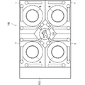
- FIG. 2 is a diagram illustrating a schematic example of a configuration of a substrate processing apparatus.
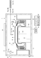
- FIG. 3 is a plan view illustrating a schematic example of a configuration of a processing unit.
- FIG. 4 is a side view illustrating a schematic example of a configuration of a processing unit.
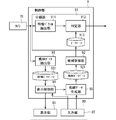
- FIG. 3 is a functional block diagram schematically illustrating an example of a configuration of a control unit. It is a figure which shows an example of a discharge state schematically in a table form. It is a flow chart which shows an example of generation processing of a classifier. It is a flow chart which shows an example of generation processing of teacher data. It is a figure which shows an example of an input screen schematically.
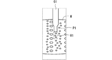
- FIG. 4 is a diagram schematically illustrating an example of a part of image data.
- FIG. 11 is a functional block diagram schematically illustrating another example of the configuration of the control unit. It is a flowchart which shows an example of an update process of a classifier. It is a figure which shows an example of a browsing screen schematically. It is a figure which shows another example of a browsing screen schematically.
- FIG. 11 is a functional block diagram schematically illustrating another example of the configuration of the control unit.
- FIG. 3 is a diagram schematically illustrating an example of image data.
- FIG. 1 is a diagram showing the overall configuration of the substrate processing apparatus 100.
- the substrate processing apparatus 100 is an apparatus that performs processing on a substrate W by supplying a processing liquid to the substrate W.
- the substrate W is, for example, a semiconductor substrate. This substrate W has a substantially disk shape.
- This substrate processing apparatus 100 can supply the processing liquid to the main surface of the substrate W.
- the substrate processing apparatus 100 can perform a cleaning process by supplying a rinsing liquid to the substrate W after supplying a cleaning liquid to the substrate W.
- the chemical liquid is SC1 liquid (a mixture of aqueous ammonia, hydrogen peroxide and water), SC2 liquid (a mixed liquid of hydrochloric acid, hydrogen peroxide and water), or DHF liquid (dilute hydrofluoric acid). Acid) and the like.
- the rinsing liquid for example, pure water is used.
- the chemical liquid and the rinsing liquid are collectively referred to as “treatment liquid”. Note that not only the cleaning process but also a coating solution such as a photoresist solution for a film forming process, a chemical solution for removing an unnecessary film, a chemical solution for etching, and the like are included in the “processing solution”.
- the substrate processing apparatus 100 includes an indexer 102, a plurality of processing units 1, and a main transfer robot 103.
- the indexer 102 has a function of carrying an unprocessed substrate W received from outside the apparatus into the apparatus and a function of carrying out the processed substrate W after the cleaning processing to the outside of the apparatus.
- the indexer 102 mounts a plurality of carriers and includes a transfer robot (both are not shown).
- a FOUP front opening unified pod
- SMIF Standard Mechanical Inter Face
- OC open cassette
- 12Twelve processing units 1 are arranged in the substrate processing apparatus 100.
- the detailed arrangement configuration is such that four towers in which three processing units 1 are stacked are arranged so as to surround the main transfer robot 103.
- four processing units 1 arranged so as to surround the main transfer robot 103 are stacked in three stages, and FIG. 1 shows one of them.
- the number of processing units 1 mounted on the substrate processing apparatus 100 is not limited to 12, and may be, for example, eight or four.
- the main transfer robot 103 is installed at the center of the four towers including the stacked processing units 1.
- the main transport robot 103 loads the unprocessed substrate W received from the indexer 102 into each processing unit 1, unloads the processed substrate W from each processing unit 1, and delivers it to the indexer 102.
- FIG. 2 is a plan view of the processing unit 1.
- FIG. 3 is a longitudinal sectional view of the processing unit 1. 2 shows a state where the substrate W is not held by the substrate holding unit 20, and FIG. 3 shows a state where the substrate W is held by the substrate holding unit 20.
- the processing unit 1 includes a substrate holding unit 20 that holds a substrate W in a horizontal posture (a posture in which a normal line of the substrate W is along the vertical direction) as main elements in the chamber 10, and a substrate held by the substrate holding unit 20.
- Three processing liquid supply units 30, 60, 65 for supplying a processing liquid to the upper surface of W, a processing cup 40 surrounding the periphery of the substrate holding unit 20, and a camera 70 for imaging the space above the substrate holding unit 20. Is provided. Further, around the processing cup 40 in the chamber 10, there is provided a partition plate 15 for vertically partitioning the inner space of the chamber 10.
- the chamber 10 includes a side wall 11 extending in the vertical direction, a ceiling wall 12 closing the upper side of a space surrounded by the side wall 11, and a floor wall 13 closing the lower side.
- the space surrounded by the side wall 11, the ceiling wall 12, and the floor wall 13 is a processing space for the substrate W.
- a part of the side wall 11 of the chamber 10 is provided with a loading / unloading port for the main transfer robot 103 to load and unload the substrate W with respect to the chamber 10, and a shutter for opening and closing the loading / unloading port. Omitted).
- the fan filter unit 14 includes a fan and a filter (for example, a HEPA filter) for taking in air in the clean room and sending it out into the chamber 10, and forms a downflow of clean air in a processing space in the chamber 10.
- a punching plate having a large number of blowout holes may be provided directly below the ceiling wall 12.
- the substrate holding unit 20 is, for example, a spin chuck.
- the substrate holding section 20 includes a disk-shaped spin base 21 fixed in a horizontal posture to an upper end of a rotating shaft 24 extending in the vertical direction.
- a spin motor 22 for rotating a rotating shaft 24 is provided below the spin base 21.
- the spin motor 22 rotates the spin base 21 via a rotation shaft 24 in a horizontal plane.
- a cylindrical cover member 23 is provided so as to surround the spin motor 22 and the rotation shaft 24.
- the outer diameter of the disc-shaped spin base 21 is slightly larger than the diameter of the circular substrate W held by the substrate holder 20. Therefore, the spin base 21 has a holding surface 21a facing the entire lower surface of the substrate W to be held.
- a plurality (four in the present embodiment) of chuck pins 26 are provided upright on the periphery of the holding surface 21a of the spin base 21.
- the plurality of chuck pins 26 are equally spaced along the circumference corresponding to the outer circumference of the circular substrate W (in the case of four chuck pins 26 as in the present embodiment, at 90 ° intervals). ) Is located.
- the plurality of chuck pins 26 are driven in conjunction with each other by a link mechanism (not shown) accommodated in the spin base 21.
- the substrate holding unit 20 holds the substrate W by bringing each of the plurality of chuck pins 26 into contact with the outer peripheral end of the substrate W, thereby positioning the substrate W above the spin base 21 and close to the holding surface 21a. (See FIG. 3), and the gripping can be released by separating each of the plurality of chuck pins 26 from the outer peripheral end of the substrate W.
- the spin motor 22 rotates the rotation shaft 24 in a state where the substrate holding unit 20 holds the substrate W by being gripped by the plurality of chuck pins 26, thereby rotating the rotation axis CX along the vertical direction passing through the center of the substrate W.
- the substrate W can be rotated.
- the processing liquid supply unit 30 is configured by attaching the discharge nozzle 31 to the tip of the nozzle arm 32 (see FIG. 2).
- the base end of the nozzle arm 32 is fixedly connected to a nozzle base 33.
- the nozzle base 33 is rotatable around a vertical axis by a motor (not shown). The rotation of the nozzle base 33 causes the discharge nozzle 31 to move between the processing position above the substrate holding unit 20 and the standby position outside the processing cup 40, as indicated by an arrow AR34 in FIG. It moves in an arc along the horizontal direction.
- the processing liquid supply unit 30 is configured to supply a plurality of types of processing liquids.
- the processing liquid supply unit 30 has a plurality of discharge nozzles 31. 2 and 3, two ejection nozzles 31a and 31b are shown as the ejection nozzles 31.
- the discharge nozzles 31a and 31b are fixed to a nozzle base 33 via a nozzle arm 32. Therefore, the discharge nozzles 31a and 31b move in synchronization with each other.
- the discharge nozzles 31a and 31b are provided so as to be adjacent in a horizontal plane.
- the discharge nozzle 31a is connected to a processing liquid supply source 37a via a pipe 34a
- the discharge nozzle 31b is connected to a processing liquid supply source 37b via a pipe 34b.
- On-off valves 35a and 35b are provided in the middle of the pipes 34a and 34b, respectively.
- the on-off valve 35a is opened, the processing liquid from the processing liquid supply source 37a flows through the inside of the pipe 34a and is discharged from the discharge nozzle 31a.
- the on-off valve 35b is opened, the processing liquid from the processing liquid supply source 37b is discharged.
- the gas flows through the inside of the pipe 34b and is discharged from the discharge nozzle 31b.
- SC1 liquid is discharged from the discharge nozzle 31a, and pure water is discharged from the discharge nozzle 31b, for example.
- Suckback valves 36a, 36b may be provided in the middle of the pipes 34a, 34b, respectively.
- the suck back valve 36a draws in the processing liquid from the tip of the discharge nozzle 31a by sucking the processing liquid in the pipe 34a when the discharge of the processing liquid is stopped. This makes it difficult for the processing liquid to drop from the tip of the discharge nozzle 31a as a relatively large lump (droplet) when the discharge is stopped.
- the processing unit 1 of this embodiment is provided with two processing liquid supply units 60 and 65 in addition to the processing liquid supply unit 30 described above.
- the processing liquid supply units 60 and 65 of the present embodiment have the same configuration as the processing liquid supply unit 30 described above. That is, the processing liquid supply unit 60 is configured by attaching a discharge nozzle 61 to the tip of a nozzle arm 62, and the discharge nozzle 61 is moved by an arrow AR 64 by a nozzle base 63 connected to the base end of the nozzle arm 62. As shown in the figure, the wafer moves in an arc between a processing position above the substrate holding unit 20 and a standby position outside the processing cup 40.
- the processing liquid supply unit 65 is configured by attaching a discharge nozzle 66 to the tip of a nozzle arm 67, and the discharge nozzle 66 is moved by an arrow AR 69 by a nozzle base 68 connected to the base end of the nozzle arm 67. As shown by, it moves in an arc between a processing position above the substrate holding unit 20 and a standby position outside the processing cup 40.
- the processing liquid supply units 60 and 65 may also be configured to supply a plurality of types of processing liquid, or may be configured to supply a single processing liquid.
- the processing liquid supply units 60 and 65 discharge the processing liquid onto the upper surface of the substrate W held by the substrate holding unit 20 with the respective discharge nozzles 61 and 66 positioned at the processing positions. At least one of the processing liquid supply units 60 and 65 mixes a cleaning liquid such as pure water and a pressurized gas to generate droplets, and ejects a mixed fluid of the droplets and the gas to the substrate W. It may be a two-fluid nozzle. Further, the number of processing liquid supply units provided in the processing unit 1 is not limited to three, but may be one or more. However, in the present embodiment, it is assumed that two processing liquids are sequentially switched and discharged, and therefore, two or more discharge nozzles are provided as a whole.
- Each of the discharge nozzles of the processing liquid supply units 60 and 65 is also connected to a processing liquid supply source via a pipe, similarly to the processing liquid supply unit 30, and an opening / closing valve is provided in the middle of the pipe. May be provided.
- processing using the processing liquid supply unit 30 will be described as a representative.
- the processing cup 40 is provided so as to surround the substrate holding unit 20.
- the processing cup 40 includes an inner cup 41, a middle cup 42, and an outer cup 43.
- the inner cup 41, the middle cup 42, and the outer cup 43 are provided to be able to move up and down.
- the processing liquid scattered from the peripheral edge of the substrate W falls on the inner peripheral surface of the inner cup 41.
- the dropped processing liquid is appropriately collected by the first collection mechanism.
- the inner cup 41 is lowered and the middle cup 42 and the outer cup 43 are raised, the processing liquid scattered from the periphery of the substrate W falls on the inner peripheral surface of the middle cup 42.
- the dropped processing liquid is appropriately collected by the second collection mechanism.
- the processing liquid scattered from the peripheral edge of the substrate W falls on the inner peripheral surface of the outer cup 43.
- the dropped processing liquid is appropriately collected by the third collection mechanism. According to this, different processing liquids can be appropriately collected.
- the partition plate 15 is provided so as to vertically partition the inner space of the chamber 10 around the processing cup 40.
- the partition plate 15 may be a single plate member surrounding the processing cup 40, or may be a combination of a plurality of plate members. Further, the partition plate 15 may be formed with a through hole or notch penetrating in the thickness direction.
- the nozzle bases 33, 63, 68 of the processing liquid supply units 30, 60, 65 are formed.
- a through hole (not shown) for passing a support shaft for supporting is formed.
- the outer peripheral end of the partition plate 15 is connected to the side wall 11 of the chamber 10.
- the edge of the partition plate 15 surrounding the processing cup 40 is formed in a circular shape having a diameter larger than the outer diameter of the outer cup 43. Therefore, the partition plate 15 does not prevent the outer cup 43 from moving up and down.
- an exhaust duct 18 is provided near the floor wall 13 in the side wall 11 of the chamber 10.
- the exhaust duct 18 is connected to an exhaust mechanism (not shown).
- the air passing between the processing cup 40 and the partition plate 15 is discharged from the exhaust duct 18 to the outside of the apparatus.
- the camera 70 is installed in the chamber 10 above the partition plate 15.
- the camera 70 includes, for example, an imaging element (for example, a CCD (Charge Coupled Device)) and an optical system such as an electronic shutter and a lens.
- the discharge nozzle 31 of the processing liquid supply unit 30 has a processing position (solid line position in FIG. 3) above the substrate W held by the substrate holding unit 20 and a standby position outside the processing cup 40 by the nozzle base 33 ( (Dotted line position in FIG. 3).
- the processing position is a position where the cleaning liquid is discharged from the processing liquid supply unit 30 onto the upper surface of the substrate W held by the substrate holding unit 20 to perform the cleaning processing.
- the standby position is a position where the discharge of the processing liquid is stopped and the processing liquid supply unit 30 stands by when the processing liquid supply unit 30 does not perform the cleaning process.
- a standby pod that accommodates the discharge nozzle 31 of the processing liquid supply unit 30 may be provided at the standby position.
- the camera 70 is installed so that its imaging area includes at least the tip of the discharge nozzle 31 at the processing position. More specifically, the camera 70 is installed such that the tip of the ejection nozzle 31 and the processing liquid ejected from the tip are included in the imaging region.
- the camera 70 is installed at a position where the ejection nozzle 31 at the processing position is imaged from the upper front. Therefore, the camera 70 can capture an image of the imaging region including the tip of the discharge nozzle 31 at the processing position.
- the camera 70 can also image the distal end of the discharge nozzle 61, 66 of the processing liquid supply unit 60, 65 at the processing position, and the imaging region including the processing liquid discharged from the distal end. In other words, the position of the camera 70 is adjusted so that the tips of these discharge nozzles and the discharged processing liquid are included in the imaging region.
- the discharge nozzles 31 and 66 of the processing liquid supply units 30 and 65 move in the horizontal direction within the imaging field of view of the camera 70.
- the discharge nozzle 61 of the processing liquid supply unit 60 moves in the depth direction within the imaging field of view of the camera 70.
- a camera dedicated to the processing liquid supply unit 60 may be provided separately from the camera 70.
- This camera 70 acquires a plurality of image data by imaging the imaging region over a period including at least a part of a period during which the processing liquid is discharged onto the substrate W.
- the camera 70 outputs the acquired image data to the control unit 9.
- an illumination unit 71 is provided in the chamber 10 and above the partition plate 15. Usually, since the interior of the chamber 10 is a dark room, when the camera 70 performs imaging, the illumination unit 71 irradiates the discharge nozzles 31, 61, 66 of the processing liquid supply units 30, 60, 65 near the processing position with light. The image data obtained by the camera 70 is output to the control unit 9.
- the user interface 80 includes a display unit 81 and an input unit 82.
- the display unit 81 is, for example, a liquid crystal display or an organic EL (Electro Luminescence) display.
- the input unit 82 is, for example, a touch panel, a mouse, or a keyboard.
- This user interface 80 is connected to the control unit 9.
- the display unit 81 displays a display image based on a display signal from the control unit 9. This display image includes, for example, image data from the camera 70.
- the input unit 82 outputs input information input by the worker to the control unit 9.
- the control unit 9 can control various components according to the input information.
- the control unit 9 controls various components of the substrate processing apparatus 100 to perform processing on the substrate W.
- the control unit 9 performs image processing on the image data acquired by the camera 70.
- the control unit 9 determines the discharge state of the processing liquid from each discharge nozzle by this image processing. This image processing will be described later in detail.
- the configuration of the control unit 9 as hardware is the same as that of a general computer. That is, the control unit 9 stores a CPU for performing various arithmetic processes, a ROM that is a read-only memory that stores a basic program, a RAM that is a readable and writable memory that stores various information, and control software and data. And a magnetic disk.
- the CPU of the control unit 9 executes a predetermined processing program, each operation mechanism of the substrate processing apparatus 100 is controlled by the control unit 9 and the processing in the substrate processing apparatus 100 proceeds.
- the CPU of the control unit 9 executes a predetermined processing program to perform image processing.
- Some or all of the functions of the control unit 9 may be realized by dedicated hardware.
- FIG. 4 is a functional block diagram schematically showing an example of the internal configuration of the control unit 9.
- the control unit 9 includes a classifier 91, a machine learning unit 92, a candidate data extraction unit 93, a display control unit 94, and a teacher data generation unit 95.
- Image data from the camera 70 is sequentially input to the classifier 91.
- the classifier 91 classifies the input image data into one of a plurality of categories. Categories can also be called classes.
- the category is a category according to the discharge state of the processing liquid from the discharge nozzle 61.
- FIG. 5 is a diagram schematically illustrating an example of a discharge state.
- the discharge state includes a state relating to the flow-down shape of the processing liquid discharged from the tip of the discharge nozzle 61. Specifically, as illustrated in FIG.
- the discharge state includes a normal discharge state in which the processing liquid flows down from the discharge nozzle 61 as a continuous flow, and the processing liquid drops as droplets when the discharge of the processing liquid is stopped.
- a dropping state There are a dropping state, a discharge stop state in which the processing liquid is not discharged, and the like. It is not desirable that drips occur, and the drips state is a kind of defective discharge state.
- the defective discharge state for example, a liquid splash state in which the processing liquid jumps at a liquid landing point on the substrate W, and the like can be cited.
- a description will be given by employing a drop-off state as a defective discharge state.
- Each category is set according to each ejection state.
- the category C1 is a category indicating a normal ejection state
- the category C2 is a category indicating a certain defective ejection state (here, a dropping state)
- the category C3 is a category indicating a discharge stop state.
- the classifier 91 classifies the image data into categories, and the control unit 9 substantially determines the ejection state. For example, when the classifier 91 classifies the image data into the category C2, it can be determined that a drop has occurred. Therefore, the control unit 9 displays on the display unit 81 that the drop has occurred, so that the operator can see the drop. You may be notified.
- This classifier 91 is generated by the machine learning unit 92 using a plurality of teacher data. That is, it can be said that the classifier 91 is a machine-learned classifier.
- the machine learning unit 92 uses, for example, a neighborhood method, a support vector machine, a random forest, or a neural network (including deep learning) as a machine learning algorithm.
- the teacher data includes image data and a label indicating which category the image data should be classified into.
- the image data may be acquired by the camera 70.
- the application of the label can be performed by, for example, an operation performed on the user interface 80 (input unit 82) by the operator. This operation will be described later in detail.
- the machine learning unit 92 generates a classifier 91 by performing machine learning based on the teacher data.
- the classifier 91 includes a feature vector extraction unit 911, a determination unit 912, and a storage medium in which a determination database 913 is stored.
- Image data from the camera 70 is sequentially input to the feature vector extraction unit 911.
- the feature vector extraction unit 911 extracts a feature vector of image data according to a predetermined algorithm.
- This feature vector is a vector that can indicate a feature according to the ejection state of the ejection nozzle.
- a known algorithm can be adopted as the algorithm.
- the feature vector extraction unit 911 outputs the feature vector to the determination unit 912.
- the judgment database 913 stores a plurality of feature vectors (hereinafter, referred to as reference vectors) generated from the plurality of teacher data by the machine learning unit 92, and the reference vectors are classified into each of the categories C1 to C3. I have. Specifically, the machine learning unit 92 generates a plurality of reference vectors by applying the same algorithm as the feature vector extraction unit 911 to a plurality of teacher data. Then, the machine learning unit 92 assigns a label (correct category) of teacher data to the reference vector.
- reference vectors a plurality of feature vectors
- the determination unit 912 classifies image data (frames) based on the feature vector input from the feature vector extraction unit 911 and a plurality of reference vectors stored in the determination database 913.
- the determination unit 912 may specify a reference vector whose feature vector is closest, and may classify the frame into the category of the specified reference vector (nearest neighbor method). Accordingly, the determination unit 912 can classify the frame input to the classifier 91 (the feature vector extraction unit 911) into one of the categories C1 to C3.
- the candidate data extraction unit 93, the display control unit 94, and the teacher data generation unit 95 are functional units related to generation of teacher data.
- Image data obtained by the camera 70 is input to the candidate data extraction unit 93.
- the candidate data extracting unit 93 stores, in the storage medium, image data acquired during a candidate period described below, among the image data, as teacher data candidates (hereinafter, referred to as candidate data).
- the candidate period is a period including at least a part of the period during which the processing liquid is discharged from the discharge nozzle 61.
- the candidate period includes a timing at which the discharge state of the processing liquid is changed. More specifically, the period includes a discharge stop timing for stopping the discharge of the processing liquid from the discharge nozzle 61, for example.
- This candidate period can be set shorter than the discharge period in which the processing liquid is discharged from the discharge nozzle 61 to the substrate W. In this candidate period, the processing liquid is initially discharged from the discharge nozzle 61, and the discharge of the processing liquid is stopped in the middle of the candidate period.
- image data showing a state in which the processing liquid flows down as a continuous flow includes image data showing a state in which the discharge of the processing liquid from the discharge nozzle 61 is stopped. Further, when a drop occurs when the ejection is stopped, the image data includes a state in which the drop has occurred. That is, by storing a plurality of data within the candidate period as candidate data, image data corresponding to each of the categories C1 to C3 can be stored as candidate data.
- the storage medium on which the candidate data is stored may be the same as the storage medium on which the determination database 913 is stored, or may be another storage medium.
- the plurality of candidate data stored in the storage medium is also referred to as a candidate database 931.
- the display control unit 94 reads candidate data from the storage medium in response to the input of the input unit 82 by the operator, and causes the display unit 81 to display the candidate data. Thereby, the worker can visually recognize the candidate data on the display unit 81.
- the worker visually recognizes the candidate data displayed on the display unit 81 and selects candidate data to be adopted as teacher data.
- the operator inputs to the input unit 82 designating candidate data to be adopted as teacher data, and inputs a label to be assigned to the candidate data to the input unit 82. For example, a label “normal ejection state” is given to image data showing a normal ejection state.
- the teacher data generation unit 95 receives the candidate data being displayed from the display control unit 94 in response to the input related to the label to the input unit 82, and transmits the information of the label input to the input unit 82 by the operator. Receive from 82.
- the teacher data generation unit 95 stores the candidate data and the label in the storage medium as teacher data in association with each other.
- the worker visually recognizes other candidate data in order, and determines whether or not to adopt the data as teacher data. Then, the worker inputs a label for candidate data to be adopted as teacher data. Thereby, a plurality of teacher data is stored in the storage medium.
- the storage medium in which the teacher data is stored may be the same as the storage medium in which the determination database 913 or the candidate database 931 is stored, or may be another storage medium.
- the plurality of teacher data stored in the storage medium is also referred to as a teacher database 921.
- FIG. 6 is a flowchart showing an example of the generation processing of the classifier 91.
- the classifier 91 is generated before the installation of the substrate processing apparatus 100 (that is, before shipment) will be described.
- step S1 teacher data is generated.
- FIG. 7 is a flowchart showing an example of the teacher data generation process in step S1 of FIG.
- the substrate W is held by the substrate holding unit 20. Specifically, the substrate W is transferred onto the substrate holding unit 20 by the main transfer robot 103. The substrate holding unit 20 holds the transported substrate W substantially horizontally.
- step S12 the control unit 9 controls, for example, the rotating mechanism of the processing liquid supply unit 60 to move the discharge nozzle 61 to the processing position.
- the processing liquid supply unit 60 will be described, but the processing liquid supply units 30 and 65 may be used.
- step S13 the control unit 9 causes the camera 70 to take an image, for example, triggered by the movement of the discharge nozzle 61.
- the camera 70 captures an image of the imaging region at a predetermined frame rate (for example, 60 frames / second), and sequentially outputs the obtained image data to the control unit 9.
- step S14 the control unit 9 controls the spin motor 22 to rotate the substrate W in a horizontal plane, and in step S15, performs a processing liquid discharge process. Specifically, the control unit 9 outputs an open signal to the on-off valve connected to the discharge nozzle 61 to discharge the processing liquid from the discharge nozzle 61 onto the upper surface of the substrate W. Then, for example, when a predetermined processing period has elapsed, the control unit 9 outputs a close signal to the on-off valve to stop the discharge of the processing liquid from the discharge nozzle 61. If a suck-back valve is provided, a suction signal is output to the suck-back valve.
- step S16 the control unit 9 causes the camera 70 to end the imaging, and in step S17, the control unit 9 controls the spin motor 22 to stop the rotation of the substrate W.
- the candidate data extraction unit 93 stores the image data acquired by the camera 70 during the candidate period in the storage medium as candidate data.
- the candidate period is, for example, about several seconds.
- the candidate data extracting unit 93 can determine the candidate period based on the timing at which the discharge nozzle 61 stops discharging. Specifically, the candidate data extracting unit 93 may determine a period from a timing earlier than the ejection stop timing by a first predetermined amount to a timing later than the ejection stop timing by a second predetermined amount as the candidate period. .
- the opening / closing valve for controlling the discharge / stop of the processing liquid from the discharge nozzle 61 is controlled by the controller 9 as described above. Then, after the control unit 9 outputs the close signal to the on-off valve, the discharge of the processing liquid from the discharge nozzle 61 is stopped after a delay time corresponding to the length of the pipe or the like. Since this delay time is usually not so long, the candidate data extraction unit 93 may determine the candidate period based on the output timing of outputting a close signal to the on-off valve. That is, this output timing may be regarded as the discharge stop timing. Alternatively, when a suck back valve is provided, the candidate period may be determined based on the output timing of the suction signal to the suck back valve. Alternatively, when another ejection stop signal is used, that ejection stop signal may be employed.
- the candidate data extracting unit 93 may specify the ejection stop timing based on the image data from the camera 70.
- the processing liquid from the discharge nozzle 61 is captured in a discharge region R ⁇ b> 1 (see also FIG. 15) extending from the tip of the discharge nozzle 61 in the processing liquid discharge direction.
- the processing liquid when the processing liquid is being discharged, the liquid column-shaped processing liquid appears in the discharge region R1, and when the processing liquid is not discharged, the processing liquid does not appear in the discharge region R1.
- the processing liquid is imaged in the ejection region R1, the brightness value (or gray scale pixel value) of the pixels in the ejection region R1 becomes relatively high, and the distribution varies.
- the processing liquid is not imaged in the ejection region R1
- the upper surface of the substrate W is imaged, so that the luminance values of the pixels in the ejection region R1 are relatively low and the distribution is more uniform.
- the candidate data extraction unit 93 determines that the processing liquid is discharged when the statistic is higher than the reference value, and stops the processing liquid discharge when the statistic is smaller than the reference value.
- the reference value can be set, for example, by simulation or experiment.
- the candidate data extraction unit 93 may specify the ejection stop timing based on the result of this determination. According to this, the discharge stop timing can be specified with high accuracy. Therefore, even if the candidate period is set short, the discharge stop timing can be included in the candidate period. As a result, in the candidate period, image data corresponding to the categories C1 to C3 can be obtained.
- the candidate data extracting unit 93 stores a plurality of candidate data acquired in the candidate period as a group of candidate data in a storage medium. Further, the candidate data extracting unit 93 may store information accompanying the candidate data (hereinafter, also referred to as additional information) in a storage medium in association with the candidate data group. Examples of the accompanying information include, for example, information for identifying the processing unit 1 to which the camera 70 that has obtained the candidate data belongs, date and time information when the candidate data has been obtained, and information for identifying the processing liquid supply unit shown in the candidate data. Can be.
- a candidate data group can be stored in the storage medium for each processing unit 1. Further, by performing the processing while changing the processing liquid supply unit in each processing unit 1, a candidate data group can be stored in the storage medium for each processing liquid supply unit.
- FIG. 8 is a diagram schematically showing an example of an input screen IS1 for selecting candidate data.
- the input screen IS1 is provided with an image display area IR1, a list display area TR1, and a button area BR1.
- the image display area IR1 is a rectangular area and is an area where candidate data is displayed. In the example of FIG. 8, the image display area IR1 is located at the upper left of the input screen IS1.
- the button area BR1 includes a plurality of buttons for designating candidate data to be displayed in the image display area IR1.
- the button area BR1 is located to the right of the image display area IR1.
- An operation on a button in the button area BR1 is realized by an input to the input unit 82.
- the button area BR1 includes a unit selection area U1, a date selection area D1, an image selection area Ca1, and a label selection area L1.
- the unit selection area U1 includes a button for selecting one of the twelve processing units 1.
- the unit selection area U1 includes buttons “1” to “12”, and these numbers indicate the identification numbers of the processing units 1.
- the date selection area D1 includes a button for designating the date on which the candidate data was obtained.
- the date selection area D1 includes a "previous day” button and a "next day” button. By operating these buttons, a date can be selected.
- the date selection area D1 may include a frame in which a date is displayed, such as “2016/3/25”. By inputting to the input unit 82, the date may be directly input by operating the frame.
- the image selection area Ca1 includes a button for designating candidate data from the candidate data group.
- the image selection area Ca1 includes a “previous image” button and a “next image” button, and by operating these, candidate data can be selected.
- the image selection area Ca1 may include a frame for displaying the number of candidate data with respect to the total number of candidate data of the candidate data group, such as “1/64”. By inputting to the input unit 82, an operation may be performed on this frame to directly specify candidate data.
- the label selection area L1 includes a button for designating a label.
- the label selection area L1 includes buttons for a “normal ejection state”, a “dropping state”, and a “discharge stop state”.
- the operator operates the buttons in the unit selection area U1 to select one of the processing units 1 and operates the buttons and the like in the date selection area D1 to specify the date by inputting to the input unit 82.
- the display control unit 94 reads a candidate data group that satisfies the conditions (the processing unit 1 and the date) (for example, reads from the candidate database 931 or reads the candidate data group).
- the history database 961 (see FIG. 10) is read), and the list is displayed in the list display area TR1 in a table format. In the example of FIG. 8, in the list display area TR1, the acquisition time of the candidate data group and the processing liquid supply unit appearing in the candidate data group are displayed.
- the operator can select one from the list in this table. This selection is also realized by input to the input unit 82.
- the display control unit 94 converts one candidate data included in the selected candidate data group into an image. It is displayed in the display area IR1. For example, the first candidate data included in the candidate data group is displayed in the image display area IR1.
- the operator operates a button or the like in the image selection area Ca1 by inputting to the input unit 82 to sequentially display the candidate data included in the candidate data group in the image display area IR1. For example, when the operator performs an operation on a button indicating “next image”, the display control unit 94 terminates the display of the candidate data displayed in the image display area IR1, and sequentially displays the candidate data in time series. The located candidate data is displayed in the image display area IR1.
- the worker visually recognizes the candidate data displayed in the image display area IR1, and determines whether or not to adopt the candidate data as teacher data. That is, the worker selects image data to be adopted as teacher data from the candidate data. If the worker decides to adopt the candidate data as teacher data, a correct category is given as a label to the image data. Specifically, the operator operates a button in the label selection area L1 by inputting to the input unit 82 to input a correct label for the candidate data. In response to the input to the input unit 82, the teacher data generation unit 95 receives the candidate data currently displayed in the image display area IR1 from the display control unit 94, and responds to the candidate data in response to the input. The candidate data and the label associated with each other are stored in the storage medium as teacher data.
- the worker can generate a plurality of teacher data (teacher database 921) by repeatedly performing the above operation.
- the plurality of teacher data is stored in a storage medium.
- the teacher data generation unit 95 assigns a label corresponding to the discharge state of the processing liquid in at least one of the image data to the image data based on the input to the input unit 82 by the worker, Generate teacher data.
- the machine learning unit 92 reads the teacher data from the teacher database 921, and generates a classifier 91 by a learning process based on the teacher data.
- the classifier 91 can also be called a trained model.
- the machine learning unit 92 may generate the classifier 91 for each processing unit 1 or for each processing liquid supply unit. Alternatively, the machine learning unit 92 may generate the classifier 91 according to the combination of the processing unit 1 and the processing liquid supply unit.
- step S3 the accuracy of the classifier 91 is evaluated.
- the image data is input to the classifier 91, and the classifier 91 classifies the image data.
- the classifier 91 calculates the degree to which the input image data falls into each category (the degree of matching), and classifies the image data into the category having the highest degree of matching.
- the “normal discharge state” is classified into a category C1
- the “blind state” is classified into a category C2
- the “discharge stopped state” is classified into a category C3.
- the relevance to the correct category is sufficiently higher than the other relevance, it can be said that the classifier 91 has correctly classified. Conversely, if the relevance is low, it can be said that the classifier 91 still has room for improvement.
- control unit 9 determines whether the relevance to the correct category is higher or lower than the reference value. When the relevance is lower than the reference value, in step S2, the machine learning unit 92 performs the learning process again. Update the classifier 91. Note that the machine learning unit 92 may perform a learning process to update the classifier 91 after newly adding teacher data.
- the classifier 91 can be determined to be appropriate. However, if only the accuracy evaluation is performed on the classification result of one image data, the evaluation is insufficient. Therefore, it is desirable to perform the accuracy evaluation on the classification result of a plurality of image data. More specifically, when the relevance to a correct category is higher than a reference value in a predetermined number of classification results, the classifier 91 may be determined to be appropriate. If the classifier 91 determines that it is appropriate, the process ends.
- image data obtained by the camera 70 and showing various ejection states is adopted as teacher data. Therefore, a classifier 91 that can classify the ejection state can be generated.
- the control unit 9 stores the image data in the short candidate period including the timing at which the discharge state of the processing liquid changes (for example, the discharge stop timing) as a teacher data candidate (candidate data) in the storage medium. I have. Therefore, the number of candidate data can be reduced as compared with the case where all the image data in the processing period are stored as candidate data. Therefore, the operator can reduce the labor required for checking the candidate data, and the image data can be easily selected. Also, the required capacity of the storage medium can be reduced.
- FIG. 9 is a diagram schematically illustrating an example of a part of image data that has been misclassified.
- FIG. 9 shows a part of the image data in an enlarged manner.
- the processing liquid is not discharged from the discharge nozzle 61.
- a substantially circular pattern P1 is discretely included on the upper surface of the substrate W of the image data.
- the pattern P1 is, for example, a pattern formed on the upper surface of the substrate W.
- the patterns P ⁇ b> 1 are arranged at intervals in a substantially vertical direction immediately below the tip of the discharge nozzle 61.
- the pixel value of the pixel in the circular pattern P1 may be larger than the pixel value of the pixel on the upper surface of another substrate W.
- the distribution of pixel values in the ejection region R1 immediately below the tip of the ejection nozzle 61 can be similar to the distribution of pixel values in the ejection region when a drop occurs. Therefore, the classifier 91 can classify the image data into the category C2 (fluttering state) even though the flashing has not actually occurred.
- the pattern P1 is formed in a relatively large area of the substrate W, but may be formed in a predetermined area of a part of the upper surface of the substrate W.
- the pattern P1 can be formed by reflecting light from the illumination unit 71 on the upper surface of the substrate W. For example, during the rotation of the substrate W, light irregularly reflected by the metal pattern in the predetermined region on the upper surface of the substrate W forms the pattern P1. Then, when the predetermined region enters immediately below the nozzle 61 with the rotation of the substrate W, the pattern P1 is also included in the ejection region R1 immediately below the nozzle 61 in the image data captured by the camera 70.
- the distribution of the pixel values in the ejection region R1 can be similar to the distribution of the pixel values in the ejection region when a drop occurs. Therefore, the classifier 91 can classify the image data into the category C2 (fluttering state) even though the flashing has not actually occurred.
- misclassified image data As teacher data and update the classifier 91 by re-learning based on the teacher data.
- FIG. 10 is a diagram schematically showing an example of the internal configuration of control unit 9A.
- the control unit 9A has the same configuration as the control unit 9 except for the presence or absence of the history data storage control unit 96.
- the image data acquired by the camera 70 and the classification result information by the classifier 91 are input to the history data storage control unit 96.
- the history data storage control unit 96 associates each image data with its classification result, and stores these in a storage medium as history data.
- the history data storage control unit 96 may store a history data group for each process on the substrate W in a storage medium. That is, each time a process is performed on the substrate W, a plurality of pieces of history data acquired by the process may be stored in the storage medium as a group of history data.
- the history data storage control unit 96 associates the accompanying information (for example, the identification information of the processing unit 1, the date and time information, and the identification information of the processing liquid supply unit) similar to the candidate data with the history data, and stores them in the storage medium. May be.
- the storage medium in which the history data is stored may be the same as or different from the storage medium in which at least one of the determination database 913, the candidate database 931 and the teacher database 921 is stored.
- the plurality of pieces of history data stored in the storage medium will also be referred to as a history database 961.
- the input unit 82 can receive an input for instructing display of history data.
- the display control unit 94 causes the display unit 81 to display the history data (image data and the classification result) in response to the input.
- the operator visually checks whether the classification result of the image data displayed on the display unit 81 is correct. When this classification is incorrect, that is, when the image data is incorrectly classified, the operator inputs a correct category different from the misclassified category as a label by inputting to the input unit 82.
- the teacher data generation unit 95 associates the image data displayed on the display unit 81 with the label input to the input unit 82, and stores the new data as new teacher data in the storage medium. That is, the teacher database 921 is updated.
- FIG. 11 is a flowchart showing an example of the updating process of the classifier 91 by relearning.
- the operator selects the misclassified image data as teacher data. Specifically, first, the operator causes the display unit 81 to display the browsing screen PS1 by inputting to the input unit 82.
- FIG. 12 is a diagram schematically showing an example of the browsing screen PS1.
- the viewing screen PS1 is similar to the input screen IS1 except for the following points. That is, history data, not candidate data, is displayed in the image display area IR1.
- a list of history data groups at the designated processing unit 1 and date and time is displayed in the image display area IR1.
- an item of “pass / fail” is provided in the table of the list display area TR1.
- the item of “quality” indicates the quality of the discharge state of the processing liquid.
- the category result of the history data included in the history data group includes the category C2 (flushed state)
- the discharge state of the processing liquid is poor, and thus the processing liquid is defective. Is shown for the history data group. If nothing is displayed in the item of “pass / fail”, it indicates that the processing liquid has been normally discharged and stopped normally.
- the display control unit 94 reads the selected history data group from the history database 961 in response to the input. Then, the image data of the history data group is displayed in the image display area IR1. Then, the operator operates a button in the image selection area Ca1 by inputting to the input unit 82 to sequentially display the image data included in the history data group in the image display area IR1. In particular, the operator visually determines whether or not a drop has occurred in the image data when the discharge of the processing liquid is stopped.
- the classification result by the classifier 91 was appropriate, and the operator ends the processing.
- the classification result by the classifier 91 is inappropriate, and the image data is adopted as teacher data. That is, a correct label is given to the image data.
- the operator operates a button in the label selection area L1 by input to the input unit 82 to input a correct label for the image data. I do. For example, for the image data shown in FIG. 9, a label of "discharge stop state" is input.
- the teacher data generation unit 95 receives the image data currently displayed in the image display area IR1 from the display control unit 94, and displays a label corresponding to the input to the image data. And these are stored in the storage medium as teacher data. As a result, teacher data for re-learning can be generated.
- step S22 the machine learning unit 92 updates the classifier 91 by re-learning based on teacher data including new teacher data.
- steps S23 and S24 are executed. Steps S23 and S24 are the same as steps S3 and S4, respectively.
- the correct category for the misclassified image data can be reflected on the classifier 91. Therefore, it is possible to reduce the possibility that the updated classifier 91 will misclassify.
- a label “discharge stop state” is given to the image data that has been incorrectly classified.
- the feature vector of the misclassified image data is misclassified because it is close to the category C2 of “blurred state”.
- the later classifier 91 may easily misclassify the image data that should be classified into the category C2 in the “dropped state” into the category C3 in the “discharge stopped state”.
- a new label may be assigned to the misclassified image data. That is, another category C4 may be provided as a type of classification in addition to the categories C1 to C3.
- the category C4 may be a category indicating misclassification.
- a category (label) indicating that a pattern (for example, a pattern) P1 similar to the bleeding is formed on the upper surface of the substrate W may be employed.
- FIG. 13 is a diagram schematically showing an example of the browsing screen PS1A.
- the browsing screen PS1A in FIG. 13 is the same as that in FIG. 12 except for the types of buttons in the label selection area L1.
- the label selection area L1 includes a button of “pattern similar to dropping” as a label corresponding to the category C4.
- the teacher data generation unit 95 responds to the input and adds the input label to the history data currently displayed in the image display area IR1. Are stored in the storage medium as new teacher data.
- a dedicated label (a label corresponding to the category C4) can be given to the image data that is misclassified.
- the classifier 91 classifies all of the image data sequentially input from the camera 70 into the respective categories during the processing period using the processing liquid for the substrate W, thereby determining whether the discharge state of the processing liquid is good. Good.
- the control unit 9 (or the control unit 9A) may determine that the ejection state is defective when the image data is classified into the category C2. However, it is not necessarily limited to this.
- the control unit 9 (or the control unit 9A) may first tentatively determine the defective ejection state by a simpler process on the image data.
- FIG. 14 is a functional block diagram schematically showing an example of the internal configuration of the control unit 9B.
- the control unit 9B is the same as the control unit 9 except for the presence or absence of the temporary determination unit 97.
- Image data obtained by the camera 70 is input to the temporary determination unit 97.
- the tentative determination unit 97 performs image processing on the image data and tentatively determines whether the ejection state is defective. Specifically, the provisional determination unit 97 determines whether or not the ejection state is a drop-off state.
- FIG. 15 is a diagram schematically illustrating an example of image data.
- the ejection region R1 is a rectangular region extending from the tip of the ejection nozzle 61 in the ejection direction of the processing liquid in the image data, and has a width wider than the width of the processing liquid.
- the ejection region R1 is set to a length that does not include, for example, a liquid landing point between the processing liquid and the substrate W.
- the provisional determination unit 97 calculates the statistics of the pixel values in the ejection region R1.
- This statistic is a value corresponding to the area of the image of the processing liquid in the ejection region R1, and is, for example, a variance (for example, a standard deviation) of pixel values in the ejection region.
- the processing liquid when the processing liquid is normally discharged from the discharge nozzle 61, the processing liquid extends from one end in the vertical direction to the other in the discharge region R1, and the upper surface of the substrate W appears on both sides in the left and right direction. Since the luminance value of the pixel in which the processing liquid is captured increases due to the reflection of light on the processing liquid, the variation in the luminance value in the ejection region R1 becomes relatively high.
- the camera 70 may be a camera that acquires grayscale image data, or may be a camera that acquires color image data. In the former case, it can be said that the pixel value of the image data indicates a luminance value. In the following, a camera that acquires grayscale image data will be described as an example. However, in the case of color, a luminance value may be calculated from a pixel value and the luminance value may be used.
- the processing liquids are discretely arranged in the vertical direction in the discharge region R1 (see also FIG. 5). Therefore, the variation of the pixel value in the ejection region R1 is higher than in the normal ejection state.
- the processing liquid is not discharged from the discharge nozzle 61, the upper surface of the substrate W is captured in the discharge region R1, so that the pixel value in the discharge region R1 is relatively small and its variation is relatively small. Therefore, it is possible to detect a drop-off state (defective ejection state) according to the variance (for example, the standard deviation) of the pixel values in the ejection region R1.
- the tentative determination unit 97 calculates the variance in the ejection region R1, and determines whether the statistic (variance) is larger than a reference value. When the variance is larger than the reference value, the tentative determination unit 97 tentatively determines that a dropping state has occurred, and notifies the classifier 91 of the fact.
- the classifier 91 performs a classification process on the image data, triggered by the notification from the temporary determination unit 97. In other words, if the classifier 91 does not receive the notification from the provisional determination unit 97, it does not perform the classification process.
- the tentative determination is performed by simpler image processing, and when the tentative determination is made that a defective ejection state has occurred, the classification process by the classifier 91 is performed. Therefore, the processing in the control unit 9B can be reduced in comparison with the case where the classification processing is always performed by the classifier 91.
- a semiconductor substrate has been described as the substrate W, the present invention is not limited to this.
- a substrate such as a glass substrate for a photomask, a glass substrate for a liquid crystal display, a glass substrate for a plasma display, a substrate for an FED (Field Emission Display), a substrate for an optical disk, a substrate for a magnetic disk, or a substrate for a magneto-optical disk may be used. Good.
- the present embodiment can be applied to any apparatus that performs a predetermined process by discharging a processing liquid from a movable nozzle to a substrate.
- a rotary coating apparatus spin coater
- spin coater that discharges a photoresist liquid from a nozzle onto a rotating substrate to apply a resist, and a substrate on which a film is formed on the surface.
- the technology according to the present embodiment may be applied to a device that discharges a film removing liquid from a nozzle to an edge of the substrate or a device that discharges an etching liquid from a nozzle to the surface of a substrate.
- the processing liquid is discharged from the discharge nozzle as a continuous flow, but is not necessarily limited to this.
- the processing liquid may be discharged from the discharge nozzle in a mist state.
- the history data storage control unit 96 may store all of the image data during the processing period and the classification result of the image data on a recording medium as history data. Thereby, all the image data during the processing period can be confirmed. Alternatively, the history data storage control unit 96 may store, for example, the image data in only the candidate period and the classification result for the image data on the recording medium as history data.
- the teacher data may be stored in an external server or the like.
- the teacher data stored in the external server may be transmitted to the control unit of another substrate processing apparatus, and the control unit may generate a classifier.
Landscapes
- Cleaning Or Drying Semiconductors (AREA)
Abstract
吐出ノズルの吐出状態に応じた教師データを生成できる教師データ生成方法を提供する。教師データを生成する方法は、保持工程と処理液吐出工程と撮像工程と教師データ生成工程とを備える。保持工程において、基板を基板保持機構に略水平に保持する。処理液吐出工程において、吐出ノズルから基板の主面に向けて処理液を吐出する。撮像工程において、吐出ノズル、および、処理液吐出工程において吐出された処理液の少なくとも一部を含むように調整された撮像領域を、処理液吐出工程の少なくとも一部を含む期間に亘りカメラにより撮像し、複数の画像データを取得する。教師データ生成工程において、複数の画像データのうち少なくとも一つについて、当該画像データに写る処理液の吐出状態に応じたラベルを当該画像データに付与し、教師データを生成する。
Description
本発明は、教師データ生成方法および吐出状態の判定方法に関する。
従来から、基板に処理液を供給する基板処理装置が提案されている。この基板処理装置は、基板を水平姿勢に保持する基板保持部と、基板保持部を回転させて基板を水平面内で回転させる回転機構と、基板の上方から処理液を吐出する吐出ノズルとを備えている。
吐出ノズルから基板に向けて処理液を吐出すると、その処理液は基板の中央付近に着液し、基板の回転に伴う遠心力を受けて基板上で広がって、基板の周縁から飛散される。これにより、処理液が基板の全面に作用し、その処理液に応じた処理を基板に対して行うことができる。処理液としては、SC1液(アンモニア水、過酸化水素水および水の混合液)、SC2液(塩酸、過酸化水素水および水の混合液)およびDHF液(希フッ酸)などの薬液、または、純水などのリンス液が用いられる。
また吐出ノズルからの処理液の吐出状態をカメラで監視する技術も提案されている(例えば特許文献1)。特許文献1では、吐出ノズルの先端を含む撮像領域をカメラで撮像し、そのカメラによって取得された画像データに基づいて、吐出ノズルから処理液が吐出されているか否かを判定する。
カメラによって取得された画像データに対して、機械学習済みの分類器による分類処理を行うことが考えられる。分類のカテゴリとしては、吐出ノズルからの処理液の吐出状態に応じたカテゴリを採用できる。具体的には、当該カテゴリとしては、処理液の吐出状態が正常であることを示すカテゴリ、未だ処理液が吐出されていないことを示すカテゴリ、および、処理液の吐出状態が不良であることを示すカテゴリを採用できる。分類器は、カメラによって取得された画像データを、該当するカテゴリに分類する。
このような分類器を機械学習により生成するためには、教師データを生成する必要がある。
そこで本願は、吐出ノズルの吐出状態に応じた教師データを生成できる教師データ生成方法を提供することを目的とする。
教師データ生成方法の第1の態様は、基板処理装置における吐出ノズルの吐出状態についての教師データを生成する方法であって、基板を基板保持機構に略水平に保持する保持工程と、前記吐出ノズルから前記基板の主面に向けて処理液を吐出する処理液吐出工程と、前記吐出ノズル、および、前記処理液吐出工程において吐出された前記処理液の少なくとも一部を含むように調整された撮像領域を、前記処理液吐出工程の少なくとも一部を含む期間に亘りカメラにより撮像し、複数の画像データを取得する撮像工程と、前記複数の画像データのうち少なくとも一つについて、当該画像データに写る処理液の吐出状態に応じたラベルを当該画像データに付与し、教師データを生成する教師データ生成工程と、を備える。
教師データ生成方法の第2の態様は、第1の態様にかかる教師データ生成方法であって、前記教師データ生成工程は、前記処理液の吐出状態が変化するタイミングを含み、前記処理液吐出工程の期間よりも短い期間において前記カメラによって取得された画像データを、教師データの候補として記憶媒体に記憶する記憶工程と、前記候補から教師データとして採用する画像データを選定する選定工程と、教師データに対して、当該教師データに写る処理液の吐出状態に応じたラベルを付与するラベル付与工程とを備える。
教師データ生成方法の第3の態様は、第1または第2の態様にかかる教師データ生成方法であって、前記教師データに基づいて生成された分類器によって、画像データがあるカテゴリに誤分類されたときに、当該画像データを教師データとして採用し、当該教師データに対して、前記カテゴリに相当する第1ラベルとは別の第2ラベルを付与する工程をさらに備える。
教師データ生成方法の第4の態様は、第3の態様にかかる教師データ生成方法であって、前記第2ラベルは、誤分類されたことを示すラベルである。
教師データ生成方法の第5の態様は、第3の態様にかかる教師データ生成方法であって、前記カテゴリは、前記処理液の吐出停止の際に処理液が液滴として落下するぼた落ち状態を示すカテゴリを含み、前記第2ラベルは、前記画像データにおいて前記吐出ノズルの直下の前記基板の表面に形成された模様がぼた落ちのパターンと類似していることを示すラベルである。
吐出状態の判定方法の態様は、第1から第5の態様のいずれか一つの態様にかかる教師データ生成方法によって生成された教師データを用いて機械学習を行って分類器を生成する工程と、基板を基板保持機構に略水平に保持する工程と、前記吐出ノズルから前記基板の主面に向けて処理液を吐出する工程と、前記吐出ノズル、および、前記処理液吐出工程において吐出された前記処理液の少なくとも一部を含むように更新された撮像領域を、前記処理液吐出工程の少なくとも一部を含む期間に亘りカメラにより撮像し、複数の画像データを取得する工程と、前記吐出ノズルからの処理液の吐出状態の良否の仮判定を、前記画像データのうち前記吐出ノズルの先端から処理液の吐出方向に延びる領域内の画素値の統計量に基づいて行い、前記吐出状態が不良あると仮判定したときに、前記分類器によって、当該画像データを吐出状態に応じたカテゴリに分類する。
教師データ生成方法の第1の態様によれば、処理液の吐出状態に応じたラベルが付与された教師データを生成できる。
教師データ生成方法の第2の態様によれば、より短い候補期間において取得された画像データを教師データの候補として記憶しているので、例えば処理期間に全体において生成された画像データの全ての教師データの候補として記憶する場合に比して、教師データの候補の数を低減できる。よって、教師データの選定が容易となる。
教師データ生成方法の第3の態様によれば、再学習用の教師データを生成することができる。
教師データ生成方法の第4の態様によれば、分類精度を向上できる。
教師データ生成方法の第5の態様によれば、ぼた落ちの誤判定の抑制に資する教師データを生成することができる。
吐出状態の判定方法の態様によれば、統計量に基づく仮判定で吐出状態が不良であると判定したときに、分類器によって画像データをカテゴリに分類するので、全画像データを分類する場合に比して、処理を簡易にできる。
以下、添付される図面を参照しながら実施の形態について説明する。なお、図面は概略的に示されるものであり、説明の便宜のため、適宜、構成の省略、または、構成の簡略化がなされるものである。また、図面に示される構成などの大きさおよび位置の相互関係は、必ずしも正確に記載されるものではなく、適宜変更され得るものである。
また、以下に示される説明では、同様の構成要素には同じ符号を付して図示し、それらの名称と機能とについても同様のものとする。したがって、それらについての詳細な説明を、重複を避けるために省略する場合がある。
<基板処理装置の概要>
図1は、基板処理装置100の全体構成を示す図である。基板処理装置100は、基板Wに対して処理液を供給して基板Wに対する処理を行う装置である。基板Wは、例えば半導体基板である。この基板Wは略円板形状を有している。
図1は、基板処理装置100の全体構成を示す図である。基板処理装置100は、基板Wに対して処理液を供給して基板Wに対する処理を行う装置である。基板Wは、例えば半導体基板である。この基板Wは略円板形状を有している。
この基板処理装置100は処理液を基板Wの主面に供給することができる。例えば基板処理装置100は、基板Wに対して洗浄用の薬液を供給した後に、基板Wに対してリンス液を供給することで、洗浄処理を行うことができる。当該薬液としては、典型的には、SC1液(アンモニア水、過酸化水素水および水の混合液)、SC2液(塩酸、過酸化水素水および水の混合液)、または、DHF液(希フッ酸)などが用いられる。当該リンス液としては、例えば純水などが用いられる。本明細書では、薬液とリンス液とを総称して「処理液」と称する。なお洗浄処理のみならず、成膜処理のためのフォトレジスト液などの塗布液、不要な膜を除去するための薬液、エッチングのための薬液なども「処理液」に含まれる。
基板処理装置100は、インデクサ102、複数の処理ユニット1および主搬送ロボット103を備える。インデクサ102は、装置外から受け取った未処理の基板Wを装置内に搬入するとともに、洗浄処理の終了した処理済みの基板Wを装置外に搬出する機能を有する。インデクサ102は、複数のキャリアを載置するとともに移送ロボットを備える(いずれも図示省略)。キャリアとしては、基板Wを密閉空間に収納するFOUP(front opening unified pod)またはSMIF(Standard Mechanical Inter Face)ポッド、あるいは、収納した状態で基板Wを外気に曝すOC(open cassette)を採用することができる。移送ロボットは、当該キャリアと主搬送ロボット103との間で基板Wを移送する。
基板処理装置100には、12個の処理ユニット1が配置されている。詳細な配置構成は、3個の処理ユニット1を積層したタワーが主搬送ロボット103の周囲を囲むように4個配置されるというものである。換言すれば、主搬送ロボット103を囲んで配置された4個の処理ユニット1が3段に積層されており、図1はそのうちの1層を示している。なお、基板処理装置100に搭載される処理ユニット1の個数は12に限定されるものではなく、例えば8個または4個であっても良い。
主搬送ロボット103は、積層した処理ユニット1を含む4個のタワーの中央に設置されている。主搬送ロボット103は、インデクサ102から受け取った未処理の基板Wを各処理ユニット1に搬入するとともに、各処理ユニット1から処理済みの基板Wを搬出してインデクサ102に渡す。
次に、処理ユニット1について説明する。以下、基板処理装置100に搭載された12個の処理ユニット1のうちの1つを説明するが、他の処理ユニット1についても同様である。図2は、処理ユニット1の平面図である。また、図3は、処理ユニット1の縦断面図である。なお、図2は基板保持部20に基板Wが保持されていない状態を示し、図3は基板保持部20に基板Wが保持されている状態を示している。
処理ユニット1は、チャンバー10内に、主たる要素として、基板Wを水平姿勢(基板Wの法線が鉛直方向に沿う姿勢)に保持する基板保持部20と、基板保持部20に保持された基板Wの上面に処理液を供給するための3つの処理液供給部30,60,65と、基板保持部20の周囲を取り囲む処理カップ40と、基板保持部20の上方空間を撮像するカメラ70とを備える。また、チャンバー10内における処理カップ40の周囲には、チャンバー10の内側空間を上下に仕切る仕切板15が設けられている。
チャンバー10は、鉛直方向に沿う側壁11、側壁11によって囲まれた空間の上側を閉塞する天井壁12および下側を閉塞する床壁13を備える。側壁11、天井壁12および床壁13によって囲まれた空間が基板Wの処理空間となる。また、チャンバー10の側壁11の一部には、チャンバー10に対して主搬送ロボット103が基板Wを搬出入するための搬出入口およびその搬出入口を開閉するシャッターが設けられている(いずれも図示省略)。
チャンバー10の天井壁12には、基板処理装置100が設置されているクリーンルーム内の空気をさらに清浄化してチャンバー10内の処理空間に供給するためのファンフィルタユニット(FFU)14が取り付けられている。ファンフィルタユニット14は、クリーンルーム内の空気を取り込んでチャンバー10内に送り出すためのファンおよびフィルタ(例えばHEPAフィルタ)を備えており、チャンバー10内の処理空間に清浄空気のダウンフローを形成する。ファンフィルタユニット14から供給された清浄空気を均一に分散するために、多数の吹出し孔を穿設したパンチングプレートを天井壁12の直下に設けるようにしても良い。
基板保持部20は例えばスピンチャックである。この基板保持部20は、鉛直方向に沿って延びる回転軸24の上端に水平姿勢で固定された円板形状のスピンベース21を備える。スピンベース21の下方には回転軸24を回転させるスピンモータ22が設けられている。スピンモータ22は、回転軸24を介してスピンベース21を水平面内にて回転させる。また、スピンモータ22および回転軸24の周囲を取り囲むように筒状のカバー部材23が設けられている。
円板形状のスピンベース21の外径は、基板保持部20に保持される円形の基板Wの径よりも若干大きい。よって、スピンベース21は、保持すべき基板Wの下面の全面と対向する保持面21aを有している。
スピンベース21の保持面21aの周縁部には複数(本実施形態では4本)のチャックピン26が立設されている。複数のチャックピン26は、円形の基板Wの外周円に対応する円周上に沿って均等な間隔を空けて(本実施形態のように4個のチャックピン26であれば90°間隔にて)配置されている。複数のチャックピン26は、スピンベース21内に収容された図示省略のリンク機構によって連動して駆動される。基板保持部20は、複数のチャックピン26のそれぞれを基板Wの外周端に当接させて基板Wを把持することにより、当該基板Wをスピンベース21の上方で保持面21aに近接した水平姿勢にて保持することができるとともに(図3参照)、複数のチャックピン26のそれぞれを基板Wの外周端から離間させて把持を解除することができる。
複数のチャックピン26による把持によって基板保持部20が基板Wを保持した状態にて、スピンモータ22が回転軸24を回転させることにより、基板Wの中心を通る鉛直方向に沿った回転軸CXまわりに基板Wを回転させることができる。
処理液供給部30は、ノズルアーム32の先端に吐出ノズル31を取り付けて構成されている(図2参照)。ノズルアーム32の基端側はノズル基台33に固定して連結されている。ノズル基台33は図示を省略するモータによって鉛直方向に沿った軸のまわりで回動可能とされている。ノズル基台33が回動することにより、図2中の矢印AR34にて示すように、吐出ノズル31は基板保持部20の上方の処理位置と処理カップ40よりも外側の待機位置との間で水平方向に沿って円弧状に移動する。
図2および図3の例では、処理液供給部30は、複数種の処理液が供給されるように構成されている。具体的には、処理液供給部30は複数の吐出ノズル31を有している。図2および図3の例では、吐出ノズル31として2つの吐出ノズル31a,31bが示されている。吐出ノズル31a,31bはノズルアーム32を介してノズル基台33に固定されている。よって、吐出ノズル31a,31bは互いに同期して移動する。吐出ノズル31a,31bは水平面内で隣り合うように設けられている。
図3に例示するように、吐出ノズル31aは配管34aを介して処理液供給源37aに接続されており、吐出ノズル31bは配管34bを介して処理液供給源37bに接続されている。配管34a,34bの途中にはそれぞれ開閉弁35a,35bが設けられている。開閉弁35aが開くことにより、処理液供給源37aからの処理液が配管34aの内部を流れて吐出ノズル31aから吐出され、開閉弁35bが開くことにより、処理液供給源37bからの処理液が配管34bの内部を流れて吐出ノズル31bから吐出される。吐出ノズル31aからは例えばSC1液が吐出され、吐出ノズル31bからは例えば純水が吐出される。吐出ノズル31a,31bが処理位置で停止した状態で吐出された処理液は、基板保持部20に保持された基板Wの上面に着液する。
配管34a,34bの途中にはそれぞれサックバック弁36a,36bが設けられていてもよい。サックバック弁36aは処理液の吐出停止時において配管34a内の処理液を吸い込むことにより、吐出ノズル31aの先端から処理液を引き込む。これにより、吐出停止時において処理液が吐出ノズル31aの先端から比較的大きな塊(液滴)として落下するぼた落ちが生じにくい。サックバック弁36bも同様である。
また、本実施形態の処理ユニット1には、上記の処理液供給部30に加えてさらに2つの処理液供給部60,65が設けられている。本実施形態の処理液供給部60,65は、上記の処理液供給部30と同様の構成を備える。すなわち、処理液供給部60は、ノズルアーム62の先端に吐出ノズル61を取り付けて構成され、その吐出ノズル61は、ノズルアーム62の基端側に連結されたノズル基台63によって、矢印AR64にて示すように基板保持部20の上方の処理位置と処理カップ40よりも外側の待機位置との間で円弧状に移動する。同様に、処理液供給部65は、ノズルアーム67の先端に吐出ノズル66を取り付けて構成され、その吐出ノズル66は、ノズルアーム67の基端側に連結されたノズル基台68によって、矢印AR69にて示すように基板保持部20の上方の処理位置と処理カップ40よりも外側の待機位置との間で円弧状に移動する。処理液供給部60,65も、複数種の処理液が供給されるように構成されていてもよく、あるいは、単一の処理液が供給されるように構成されていてもよい。
処理液供給部60,65はそれぞれの吐出ノズル61,66が処理位置に位置する状態で、基板保持部20に保持された基板Wの上面に処理液を吐出する。なお、処理液供給部60,65の少なくとも一方は、純水などの洗浄液と加圧した気体とを混合して液滴を生成し、その液滴と気体との混合流体を基板Wに噴射する二流体ノズルであっても良い。また、処理ユニット1に設けられる処理液供給部は3つに限定されるものではなく、1つ以上であれば良い。ただし、本実施の形態では、2つの処理液を順次に切り替えて吐出することが前提なので、吐出ノズルは全体として2以上設けられる。処理液供給部60,65の各吐出ノズルも、処理液供給部30と同様に配管を介して処理液供給源に接続され、またその配管の途中には開閉弁が設けられ、さらにサックバック弁が設けられてもよい。以下では、代表的に処理液供給部30を用いた処理について述べる。
処理カップ40は、基板保持部20を取り囲むように設けられている。処理カップ40は内カップ41、中カップ42および外カップ43を備えている。内カップ41、中カップ42および外カップ43は昇降可能に設けられている。内カップ41、中カップ42および外カップ43が上昇した状態では、基板Wの周縁から飛散した処理液は内カップ41の内周面に当って落下する。落下した処理液は適宜に第1回収機構によって回収される。内カップ41が下降し、中カップ42および外カップ43が上昇した状態では、基板Wの周縁から飛散した処理液は中カップ42の内周面に当って落下する。落下した処理液は適宜に第2回収機構によって回収される。内カップ41および中カップ42が下降し、外カップ43が上昇した状態では、基板Wの周縁から飛散した処理液は外カップ43の内周面に当って落下する。落下した処理液は適宜に第3回収機構によって回収される。これによれば、異なる処理液をそれぞれ適切に回収することができる。
仕切板15は、処理カップ40の周囲においてチャンバー10の内側空間を上下に仕切るように設けられている。仕切板15は、処理カップ40を取り囲む1枚の板状部材であっても良いし、複数の板状部材をつなぎ合わせたものであっても良い。また、仕切板15には、厚さ方向に貫通する貫通孔または切り欠きが形成されていても良く、本実施形態では処理液供給部30,60,65のノズル基台33,63,68を支持するための支持軸を通すための貫通孔(不図示)が形成されている。
仕切板15の外周端はチャンバー10の側壁11に連結されている。また、仕切板15の処理カップ40を取り囲む端縁部は外カップ43の外径よりも大きな径の円形形状となるように形成されている。よって、仕切板15が外カップ43の昇降の障害となることはない。
また、チャンバー10の側壁11のうち床壁13の近傍には排気ダクト18が設けられている。排気ダクト18は図示省略の排気機構に連通接続されている。ファンフィルタユニット14から供給されてチャンバー10内を流下した清浄空気のうち、処理カップ40と仕切板15と間を通過した空気は排気ダクト18から装置外に排出される。
カメラ70は、チャンバー10内であって仕切板15よりも上方に設置されている。カメラ70は、例えば撮像素子(例えばCCD(Charge Coupled Device))と、電子シャッターおよびレンズなどの光学系とを備える。処理液供給部30の吐出ノズル31は、ノズル基台33によって、基板保持部20に保持された基板Wの上方の処理位置(図3の実線位置)と処理カップ40よりも外側の待機位置(図3の点線位置)との間で往復移動される。処理位置は、処理液供給部30から基板保持部20に保持された基板Wの上面に処理液を吐出して洗浄処理を行う位置である。待機位置は、処理液供給部30が洗浄処理を行わないときに処理液の吐出を停止して待機する位置である。待機位置には、処理液供給部30の吐出ノズル31を収容する待機ポッドが設けられていても良い。
カメラ70は、その撮像領域に少なくとも処理位置における吐出ノズル31の先端が含まれるように設置されている。より具体的には、吐出ノズル31の先端と、その先端から吐出される処理液とが撮像領域に含まれるように、カメラ70が設置される。本実施形態では、図3に示すように、処理位置における吐出ノズル31を前方上方から撮像する位置にカメラ70が設置される。よって、カメラ70は、処理位置における吐出ノズル31の先端を含む撮像領域を撮像することができる。同様に、カメラ70は、処理位置における処理液供給部60,65の吐出ノズル61,66の先端、および、その先端から吐出される処理液を含む撮像領域を撮像することもできる。言い換えれば、これらの吐出ノズルの先端、および、吐出された処理液が撮像領域に含まれるように、カメラ70の位置が調整される。
なお、カメラ70が図2に示す位置に設置されている場合には、処理液供給部30,65の吐出ノズル31,66についてはカメラ70の撮像視野内で横方向に移動するため、処理位置近傍での動きを適切に撮像することが可能であるが、処理液供給部60の吐出ノズル61についてはカメラ70の撮像視野内で奥行き方向に移動するため、処理位置近傍での移動量を適切に撮像できないおそれもある。このような場合は、カメラ70とは別に処理液供給部60専用のカメラを設けるようにしても良い。
このカメラ70は、基板Wに対して処理液を吐出する期間の少なくとも一部を含む期間に亘って撮像領域を撮像することにより、複数の画像データを取得する。カメラ70は、取得した画像データを制御部9へと出力する。
また、図3に示すように、チャンバー10内であって仕切板15よりも上方には照明部71が設けられている。通常、チャンバー10内は暗室であるため、カメラ70が撮像を行うときには照明部71が処理位置近傍の処理液供給部30,60,65の吐出ノズル31,61,66に光を照射する。カメラ70が取得した画像データは制御部9へと出力される。
ユーザインターフェース80は表示部81および入力部82を備えている。表示部81は例えば液晶表示ディスプレイまたは有機EL(Electro Luminescence)ディスプレイである。入力部82は例えばタッチパネル、マウスまたはキーボードである。このユーザインターフェース80は制御部9に接続されている。表示部81は制御部9からの表示信号に基づいて表示画像を表示する。この表示画像には、例えばカメラ70からの画像データが含まれる。入力部82は、作業者によって入力された入力情報を制御部9に出力する。制御部9は入力情報に応じて各種構成を制御することができる。
制御部9は基板処理装置100の各種構成を制御して基板Wに対する処理を進行する。また制御部9はカメラ70によって取得された画像データに対して画像処理を行う。制御部9は、この画像処理により、各吐出ノズルからの処理液の吐出状態を判定する。この画像処理については後に詳述する。
制御部9のハードウェアとしての構成は一般的なコンピュータと同様である。すなわち、制御部9は、各種演算処理を行うCPU、基本プログラムを記憶する読み出し専用のメモリであるROM、各種情報を記憶する読み書き自在のメモリであるRAMおよび制御用ソフトウェアやデータなどを記憶しておく磁気ディスクなどを備えて構成される。制御部9のCPUが所定の処理プログラムを実行することによって、基板処理装置100の各動作機構が制御部9に制御され、基板処理装置100における処理が進行する。また制御部9のCPUが所定の処理プログラムを実行することにより、画像処理を行う。なお制御部9の機能の一部または全部は、専用のハードウェアによって実現されてもよい。
図4は、制御部9の内部構成の一例を概略的に示す機能ブロック図である。制御部9は、分類器91、機械学習部92、候補データ抽出部93、表示制御部94および教師データ生成部95を備えている。
分類器91には、カメラ70からの画像データが順次に入力される。ここでは簡単のために、画像データには、処理液供給部60の吐出ノズル61が写っているものとして説明する。分類器91は、入力された画像データを複数のカテゴリの一つに分類する。カテゴリはクラスとも呼ばれ得る。ここでは、カテゴリは、吐出ノズル61からの処理液の吐出状態に応じたカテゴリである。図5は、吐出状態の例を概略的に示す図である。吐出状態とは、吐出ノズル61の先端から吐出された処理液の流下形状に関する状態を含む。具体的には図5に例示するように、吐出状態としては、吐出ノズル61から処理液が連続流として流下する正常吐出状態、処理液の吐出停止の際に当該処理液が液滴として落下するぼた落ち状態、および、処理液が吐出されていない吐出停止状態などの状態が挙げられる。ぼた落ちが生じることは望ましくなく、ぼた落ち状態は不良吐出状態の一種でもある。不良吐出状態の他の例としては、例えば処理液が基板W上の着液地点で跳ねる液はね状態なども挙げられる。ここでは、不良吐出状態としてぼた落ち状態を採用して説明する。
各吐出状態に応じて各カテゴリが設定される。例えばカテゴリC1は、正常吐出状態を示すカテゴリであり、カテゴリC2は、ある不良吐出状態(ここでは、ぼた落ち状態)を示すカテゴリであり、カテゴリC3は、吐出停止状態を示すカテゴリである。
分類器91が画像データをカテゴリに分類することにより、制御部9は実質的に吐出状態を判定する。例えば分類器91が画像データをカテゴリC2に分類したときには、ぼた落ちが生じたと判定できるので、制御部9は、ぼた落ちが生じたことを表示部81に表示することにより、作業者に報知してもよい。
この分類器91は、複数の教師データを用いて機械学習部92によって生成される。つまり、この分類器91は機械学習済みの分類器であるといえる。機械学習部92は、機械学習のアルゴリズムとして、例えば、近傍法、サポートベクターマシン、ランダムフォレストまたはニューラルネットワーク(ディープラーニングを含む)などを用いる。
教師データは、画像データと、その画像データがどのカテゴリに分類されるべきであるのかを示すラベルとを含んでいる。画像データはカメラ70によって取得されるとよい。ラベルの付与は、例えば作業者のユーザインターフェース80(入力部82)に対する操作によって行われ得る。この操作については後に詳述する。機械学習部92はこれらの教師データに基づいて機械学習を行って分類器91を生成する。
一例として、近傍法により画像データを分類する分類器91について説明する。分類器91は、特徴ベクトル抽出部911と、判定部912と、判定データベース913が記憶された記憶媒体とを備えている。特徴ベクトル抽出部911には、カメラ70からの画像データが順次に入力される。特徴ベクトル抽出部911は所定のアルゴリズムにしたがって画像データの特徴ベクトルを抽出する。この特徴ベクトルは吐出ノズルの吐出状態に応じた特徴を示すことができるベクトルである。当該アルゴリズムとしては、公知のアルゴリズムを採用できる。特徴ベクトル抽出部911はその特徴ベクトルを判定部912に出力する。
判定データベース913には、機械学習部92によって複数の教師データから生成された複数の特徴ベクトル(以下、基準ベクトルと呼ぶ)が記憶されており、その基準ベクトルは各カテゴリC1~C3に分類されている。具体的には、機械学習部92は複数の教師データに対して特徴ベクトル抽出部911と同じアルゴリズムを適用して複数の基準ベクトルを生成する。そして機械学習部92は、当該基準ベクトルに対して教師データのラベル(正しいカテゴリ)を付与する。
判定部912は特徴ベクトル抽出部911から入力された特徴ベクトルと、判定データベース913に記憶された複数の基準ベクトルとに基づいて画像データ(フレーム)を分類する。例えば判定部912は特徴ベクトルが最も近い基準ベクトルを特定し、特定した基準ベクトルのカテゴリにフレームを分類してもよい(最近傍法)。これにより、判定部912は、分類器91(特徴ベクトル抽出部911)に入力されたフレームをカテゴリC1~C3のうち一つに分類することができる。
候補データ抽出部93、表示制御部94および教師データ生成部95は、教師データの生成に関する機能部である。候補データ抽出部93には、カメラ70によって取得された画像データが入力される。候補データ抽出部93は当該画像データのうち、以下で説明する候補期間内に取得された画像データを、教師データの候補(以下、候補データと呼ぶ)として記憶媒体に記憶する。
候補期間は吐出ノズル61から処理液が吐出される期間の少なくとも一部を含む期間である。またこの候補期間には、処理液の吐出状態を変化させるタイミングが含まれる。より具体的には、例えば吐出ノズル61からの処理液の吐出を停止させる吐出停止タイミングを含む期間である。この候補期間は、吐出ノズル61から基板Wへと処理液が吐出される吐出期間よりも短く設定され得る。この候補期間において、初期的には吐出ノズル61から処理液が吐出され、候補期間の途中で処理液の吐出が停止されるので、候補期間内の複数の画像データは、吐出ノズル61から処理液が連続流として流下する状態が写る画像データと、吐出ノズル61からの処理液の吐出が停止した状態が写る画像データとを含む。また吐出停止の際にぼた落ちが生じた場合には、そのぼた落ちが生じた状態が写る画像データも含まれる。つまり、候補期間内の複数のデータを候補データとして記憶することで、各カテゴリC1~C3に対応した画像データを候補データとして記憶することができる。
候補データが記憶される記憶媒体は判定データベース913が記憶される記憶媒体と同じであってもよく、これとは別の記憶媒体であってもよい。以下では、記憶媒体に記憶された複数の候補データを候補データベース931とも呼ぶ。
表示制御部94は作業者による入力部82の入力に応答して候補データを記憶媒体から読み出し、その候補データを表示部81に表示させる。これにより、作業者は候補データを表示部81で視認することができる。
作業者は、表示部81に表示された候補データを視認し、教師データとして採用する候補データを選定する。作業者は、教師データとして採用する候補データを指定する入力を入力部82に対して行うとともに、その候補データに付与するラベルを入力部82に入力する。例えば正常吐出状態が写る画像データに対しては、「正常吐出状態」のラベルを付与する。
教師データ生成部95は入力部82へのラベルに関する入力に応答して、表示中の候補データを表示制御部94から受け取り、また作業者によって入力部82に入力されたラベルの情報を当該入力部82から受け取る。教師データ生成部95は、当該候補データと当該ラベルとを互いに対応付けて教師データとして記憶媒体に記憶する。
作業者は他の候補データについても順次に視認し、教師データとして採用するか否かを判断する。そして作業者は、教師データとして採用する候補データに対してラベルを入力する。これにより、記憶媒体には、複数の教師データが記憶される。
教師データが記憶される記憶媒体は判定データベース913または候補データベース931が記憶される記憶媒体と同じであってもよく、これらとは別の記憶媒体であってもよい。以下では、記憶媒体に記憶された複数の教師データを教師データベース921とも呼ぶ。
図6は、分類器91の生成処理の一例を示すフローチャートである。ここでは一例として、基板処理装置100の据え付け時前(つまり出荷前)に分類器91を生成する場合について述べる。図6に例示するように、まずステップS1にて、教師データを生成する。
図7は、図6のステップS1の教師データの生成処理の一例を示すフローチャートである。まずステップS11にて、基板保持部20に基板Wが保持される。具体的には、主搬送ロボット103によって基板Wが基板保持部20上に搬送される。基板保持部20は、搬送された基板Wを略水平に保持する。
次にステップS12にて、制御部9は例えば処理液供給部60の回動機構を制御して、吐出ノズル61を処理位置に移動させる。なおここでは一例として、処理液供給部60を用いて説明するものの、処理液供給部30,65を用いてもよい。
次にステップS13にて、制御部9は例えば吐出ノズル61の移動を契機として、カメラ70に撮像を行わせる。カメラ70は所定のフレームレート(例えば60フレーム/秒)で撮像領域を撮像し、取得した画像データを制御部9に順次に出力する。
次にステップS14にて、制御部9は、スピンモータ22を制御して基板Wを水平面内で回転させ、ステップS15にて、処理液の吐出処理を行う。具体的には、制御部9は、吐出ノズル61に接続された開閉弁へと開信号を出力して、吐出ノズル61から処理液を基板Wの上面に吐出させる。そして例えば所定の処理期間が経過したときに、制御部9は当該開閉弁へと閉信号を出力して吐出ノズル61からの処理液の吐出を停止させる。サックバック弁が設けられている場合には、サックバック弁に吸い込み信号を出力する。次にステップS16にて、制御部9はカメラ70に撮像を終了させ、ステップS17にて、制御部9はスピンモータ22を制御して、基板Wの回転を停止させる。
次にステップS18にて、候補データ抽出部93は、候補期間においてカメラ70によって取得された画像データを、候補データとして記憶媒体に記憶する。候補期間は例えば数秒程度である。
なお候補データ抽出部93は、この候補期間を、吐出ノズル61の吐出停止タイミングに基づいて決定することができる。具体的には、候補データ抽出部93は吐出停止タイミングよりも第1所定量だけ早いタイミングから、吐出停止タイミングよりも第2所定量だけ遅いタイミングまでの期間を、候補期間として決定してもよい。
ところで、吐出ノズル61からの処理液の吐出/停止を司る開閉弁は上述のように制御部9によって制御される。そして、制御部9が当該開閉弁へと閉信号を出力した時点から、配管の長さ等に応じた遅れ時間を経て、吐出ノズル61から処理液の吐出が停止される。この遅れ時間は通常はさほど長くないので、候補データ抽出部93は、当該開閉弁へと閉信号を出力する出力タイミングに基づいて候補期間を決定してもよい。つまり、この出力タイミングを吐出停止タイミングとみなしてもよい。あるいは、サックバック弁が設けられている場合には、サックバック弁への吸い込み信号の出力タイミングに基づいて候補期間を決定してもよい。あるいは、別の吐出停止信号が用いられる場合には、その吐出停止信号を採用してもよい。
あるいは、候補データ抽出部93はカメラ70からの画像データに基づいて、吐出停止タイミングを特定してもよい。カメラ70からの画像データのうち、吐出ノズル61の先端から処理液の吐出方向に延びる吐出領域R1(図15も参照)には、吐出ノズル61からの処理液が写る。具体的には、処理液が吐出されているときには、当該吐出領域R1には液柱状の処理液が写り、処理液が吐出されていないときには、当該吐出領域R1には処理液が写らない。吐出領域R1に処理液が写っているときには、吐出領域R1内の画素の輝度値(あるいは、グレースケールでの画素値)は比較的高くなり、またその分布はばらつく。逆に吐出領域R1に処理液が写っていないときには、基板Wの上面が写っているので、吐出領域R1内の画素の輝度値は比較的低くなり、またその分布はより均一となる。
よって、処理液が吐出しているときの吐出領域R1内の画素値の統計量(例えば総和または分散)は、処理液が吐出していないときの吐出領域R1の画素値の統計量(例えば総和または分散)よりも高い。そこで、候補データ抽出部93は当該統計量が基準値よりも高いときに処理液が吐出していると判断し、当該統計量が基準値よりも小さいときに処理液の吐出が停止していると判断する。基準値は例えばシミュレーションまたは実験により設定することができる。候補データ抽出部93はこの判断結果に基づいて吐出停止タイミングを特定してもよい。これによれば、高い精度で吐出停止タイミングを特定できる。よって、候補期間を短く設定しても、その候補期間に吐出停止タイミングを含めることができる。ひいては、候補期間において、カテゴリC1~C3に応じた画像データを取得することができる。
候補データ抽出部93は、この候補期間において取得された複数の候補データを、一纏まりの候補データ群として記憶媒体に記憶する。また候補データ抽出部93は、候補データに付随する情報(以下、付随情報とも呼ぶ)を、当該候補データ群に対応付けて記憶媒体に記憶するとよい。付随情報としては、例えば、候補データを取得したカメラ70が属する処理ユニット1を識別する情報、候補データを取得した日時情報、および、候補データに写る処理液供給部を識別する情報などを挙げることができる。
上述した一連の動作を、処理ユニット1を変更しながら行うことで、処理ユニット1ごとに候補データ群を記憶媒体に記憶できる。また各処理ユニット1において処理液供給部を変更しながら行うことで、処理液供給部ごとに候補データ群を記憶媒体に記憶できる。
次にステップS19にて、作業者は入力部82への入力により、候補データにラベルを付与して教師データを生成する。具体的には、まず作業者は候補データを表示部81に表示させる。図8は、候補データを選定するための入力画面IS1の一例を概略的に示す図である。入力画面IS1には、画像表示領域IR1、一覧表示領域TR1およびボタン領域BR1が設けられている。画像表示領域IR1は矩形状の領域であって、候補データが表示される領域である。図8の例では、画像表示領域IR1は入力画面IS1内の左上に位置している。
ボタン領域BR1には、画像表示領域IR1に表示する候補データを指定するための複数のボタンが含まれている。図8の例では、ボタン領域BR1は画像表示領域IR1の右に位置している。ボタン領域BR1内のボタンに対する操作は入力部82への入力によって実現される。ボタン領域BR1には、ユニット選択領域U1、日付選択領域D1、画像選択領域Ca1およびラベル選択領域L1が含まれている。
ユニット選択領域U1には、12個の処理ユニット1のうち一つを選択するためのボタンが含まれている。例えばユニット選択領域U1には、「1」~「12」のボタンが含まれており、これらの数字が処理ユニット1の識別番号を示している。
日付選択領域D1には、候補データを取得した日付を指定するためのボタンが含まれている。例えば日付選択領域D1には、「前の日」ボタンおよび「次の日」ボタンが含まれており、これらを操作することで、日付を選択できる。また日付選択領域D1には「2016/3/25」のように日付が表示される枠が含まれていてもよい。入力部82に対する入力により、この枠に対して操作を行って、日付を直接に入力できてもよい。
画像選択領域Ca1には、候補データ群から候補データを指定するためのボタンが含まれている。例えば画像選択領域Ca1には、「前の画像」ボタンおよび「次の画像」ボタンが含まれており、これらを操作することで、候補データを選択できる。また画像選択領域Ca1には、「1/64」のように候補データ群の総候補データ数に対する候補データの番号を表示する枠が含まれていてもよい。入力部82に対する入力により、この枠に対して操作を行って、候補データを直接に指定できてもよい。
ラベル選択領域L1には、ラベルを指定するためのボタンが含まれている。例えばラベル選択領域L1には、「正常吐出状態」、「ぼた落ち状態」および「吐出停止状態」のボタンが含まれている。
作業者は入力部82に対する入力により、ユニット選択領域U1内のボタンを操作して処理ユニット1の一つを選択しつつ、日付選択領域D1内のボタン等を操作して日付を指定する。表示制御部94は入力部82への当該入力に応答して、その条件(処理ユニット1および日付)を満たす候補データ群を読み出し(例として、候補データベース931から読み出し、または、当該候補データ群を履歴データベース961(図10参照)から読み出し)、その一覧を一覧表示領域TR1に表形式で表示させる。図8の例では、一覧表示領域TR1には、候補データ群の取得時刻と、その候補データ群に写る処理液供給部とが表示されている。
作業者はこの表の一覧のうちから一つを選択することができる。この選択も入力部82への入力によって実現される。作業者が入力部82に対する入力により、一覧表示領域TR1の表の中から候補データ群の一つを選択すると、表示制御部94は、選択された候補データ群に含まれる一つの候補データを画像表示領域IR1に表示させる。例えば候補データ群に含まれる最初の候補データを画像表示領域IR1に表示させる。
作業者は入力部82に対する入力により画像選択領域Ca1内のボタン等を操作して、候補データ群に含まれた候補データを順次に画像表示領域IR1に表示させる。例えば作業者が、「次の画像」を示すボタンに対して操作を行うと、表示制御部94は画像表示領域IR1に表示されている候補データの表示を終了させ、時系列的にその次に位置する候補データを画像表示領域IR1に表示させる。
作業者は、画像表示領域IR1に表示された候補データを視認して、その候補データを教師データとして採用する否かを判断する。つまり、作業者は候補データから教師データとして採用する画像データを選定する。作業者が候補データを教師データとして採用すると判断した場合には、当該画像データに対して正しいカテゴリをラベルとして付与する。具体的には、作業者は入力部82に対する入力によりラベル選択領域L1内のボタンを操作して、その候補データに対する正しいラベルを入力する。教師データ生成部95は当該入力部82への入力に応答して、その時点で画像表示領域IR1に表示された候補データを表示制御部94から受け取り、当該候補データに対して、当該入力に応じたラベルを対応付け、互いに対応付けられた候補データおよびラベルを教師データとして記憶媒体に記憶する。
作業者は上述の動作を繰り返し行うことによって、複数の教師データ(教師データベース921)を生成することができる。複数の教師データは記憶媒体に記憶される。
以上のように、教師データ生成部95は作業者による入力部82への入力に基づいて、画像データの少なくとも一つに写る処理液の吐出状態に応じたラベルを当該画像データに付与して、教師データを生成する。
次にステップS2にて、機械学習部92は教師データベース921から教師データを読み出し、その教師データに基づいた学習処理により分類器91を生成する。分類器91は学習済みモデルとも呼ばれ得る。なお機械学習部92は処理ユニット1ごと、あるいは、処理液供給部ごとに分類器91を生成してもよい。あるいは、機械学習部92は処理ユニット1および処理液供給部の組み合わせに応じて、分類器91を生成してもよい。
次にステップS3にて、当該分類器91の精度評価を行う。例えば分類器91に対して画像データを入力し、分類器91に当該画像データを分類させる。分類器91は、入力された画像データが各カテゴリに該当する度合い(該当度)を算出し、当該画像データをその該当度が最も高いカテゴリに分類する。例えば、「正常吐出状態」をカテゴリC1、「ぼた落ち状態」をカテゴリC2、「吐出停止状態」をカテゴリC3にそれぞれ分類する。この分類処理において、正しいカテゴリに対する該当度が他の該当度に比べて十分に高い場合には、分類器91は正しく分類を行うことができたといえる。逆に該当度が低い場合には、分類器91は未だ改善の余地があるといえる。
そこで、制御部9は正しいカテゴリに対する該当度が基準値よりも高いか低いかを判定し、該当度が基準値よりも低いときには、ステップS2にて、機械学習部92は再び学習処理を行って分類器91を更新する。なお教師データを新たに追加した上で、機械学習部92が学習処理を行って分類器91を更新してもよい。
正しいカテゴリに対する該当度が基準値よりも高いときには、分類器91が適正であると判断し得る。ただし、一つの画像データの分類結果に対する精度評価のみを行うと、その評価は不十分といえるので、複数の画像データの分類結果に対する精度評価を行うことが望ましい。より具体的には、所定回数の分類結果において、正しいカテゴリに対する該当度が基準値よりも高いときに、分類器91が適正であると判断するとよい。分類器91が適正であると判断すると、処理を終了する。
以上のように、本動作によれば、カメラ70によって取得されて種々の吐出状態が写る画像データを、教師データとして採用している。よって、吐出状態を分類できる分類器91を生成することができる。
しかも上述の例では、制御部9は処理液の吐出状態が変化するタイミング(例えば吐出停止タイミング)を含む短い候補期間内の画像データを教師データの候補(候補データ)として記憶媒体に記憶している。よって、処理期間内の全ての画像データを候補データとして記憶する場合に比べて、候補データの数を低減することができる。したがって、作業者は候補データのチェックに要する手間を低減することができ、画像データの選定が容易となる。また記憶媒体の必要容量も低減できる。
基板処理装置100の据え付け後(つまり出荷後)においても分類器91の更新が望まれる場合がある。例えば分類器91が画像データを誤分類した場合には、以後、その画像データと同様な画像データを誤分類しないように分類器91を更新することが望まれる。
図9は、誤分類された画像データの一部の一例を概略的に示す図である。図9では、画像データの一部を拡大して示している。この画像データにおいて、吐出ノズル61から処理液は吐出されていない。またこの画像データの基板Wの上面には、略円形の模様P1が離散的に含まれている。この模様P1は、例えば、基板Wの上面に形成されたパターンである。図9の例では、吐出ノズル61の先端の直下において、模様P1は略縦方向に間隔を空けて並んでいる。この円形の模様P1における画素の画素値は他の基板Wの上面における画素の画素値よりも大きい場合がある。この場合、画像データのうち、吐出ノズル61の先端の直下の吐出領域R1内の画素値の分布は、ぼた落ちが生じたときの当該吐出領域内の画素値の分布に類似し得る。したがって、実際にはぼた落ちが生じていないにも関わらず、分類器91は当該画像データをカテゴリC2(ぼた落ち状態)に分類し得る。
また、図9の例では、模様P1は基板Wの比較的広い領域に形成されているものの、基板Wの上面の一部の所定領域に形成される場合もある。この模様P1は、照明部71からの光が基板Wの上面で反射することによって形成され得る。例えば、基板Wの回転中に基板Wの上面の当該所定領域の金属パターンで乱反射した光が模様P1を形成する。そして、基板Wの回転に伴って当該所定領域がノズル61の直下に進入すると、カメラ70によって撮像された画像データにおいても、ノズル61の直下の吐出領域R1において模様P1が含まれる。この場合でも、吐出領域R1内の画素値の分布は、ぼた落ちが生じたときの当該吐出領域内の画素値の分布に類似し得る。したがって、実際にはぼた落ちが生じていないにも関わらず、分類器91は当該画像データをカテゴリC2(ぼた落ち状態)に分類し得る。
以後、このような誤分類が生じる可能性を低減すべく、誤分類した画像データを教師データとして採用し、その教師データに基づいた再学習により分類器91を更新することが望ましい。
図10は、制御部9Aの内部構成の一例を概略的に示す図である。制御部9Aは、履歴データ記憶制御部96の有無を除いて、制御部9と同様の構成を有している。履歴データ記憶制御部96には、カメラ70によって取得された画像データと、分類器91による分類結果情報とが入力される。履歴データ記憶制御部96は、各画像データとその分類結果とを互いに対応付け、これらを履歴データとして記憶媒体に記憶する。履歴データ記憶制御部96は、基板Wに対する処理ごとの履歴データ群を記憶媒体に記憶してもよい。つまり、基板Wに対する処理が行われる度に、その処理によって取得された複数の履歴データを一纏まりの履歴データ群として記憶媒体に記憶してもよい。また履歴データ記憶制御部96は、候補データと同様な付随情報(例えば処理ユニット1の識別情報、日時情報および処理液供給部の識別情報)を履歴データに対応付けて、これらを記憶媒体に記憶してもよい。
履歴データが記憶される記憶媒体は、判定データベース913、候補データベース931および教師データベース921の少なくともいずれか一つが記憶される記憶媒体と同じであってもよく、異なっていてもよい。以下では、記憶媒体に記憶された複数の履歴データを履歴データベース961とも呼ぶ。
入力部82は、履歴データの表示を指示するための入力を受け付けることができる。作業者が当該入力を行うと、表示制御部94は当該入力に応答して、表示部81に履歴データ(画像データおよび分類結果)を表示させる。
作業者は、表示部81に表示された画像データの分類結果が正しいかどうかを目視で確認する。この分類が正しくない、つまり、画像データが誤分類されたときには、作業者は入力部82に対する入力によって、誤分類されたカテゴリとは別の正しいカテゴリをラベルとして入力する。教師データ生成部95は、表示部81に表示された画像データと、入力部82に入力されたラベルとを互いに対応付けて、新たな教師データとして記憶媒体に記憶する。つまり、教師データベース921を更新する。
図11は、再学習による分類器91の更新処理の一例を示すフローチャートである。まずステップS21にて、作業者は、誤分類した画像データを教師データとして選択する。具体的には、まず作業者は入力部82に対する入力により、表示部81に閲覧画面PS1を表示させる。
図12は、閲覧画面PS1の一例を概略的に示す図である。閲覧画面PS1は、次に説明する点を除いて入力画面IS1と同様である。すなわち、画像表示領域IR1には、候補データではなく履歴データが表示される。一覧表示領域TR1には、指定された処理ユニット1および日時における履歴データ群の一覧が表示される。また一覧表示領域TR1の表には、「良否」の項目が設けられている。この「良否」の項目には、処理液の吐出状態の良否が示される。より具体的な一例として、履歴データ群に含まれる履歴データの分類結果にカテゴリC2(ぼた落ち状態)が含まれている場合には、処理液の吐出状態は不良であるので、不良であることを示す黒丸がその履歴データ群に対して示される。「良否」の項目に何も表示されていない場合、それは、処理液が正常に吐出されて正常に停止したことを示す。
作業者が入力部82への入力により、吐出状態が不良と判定された履歴データ群を選択すると、表示制御部94は当該入力に応答して、選択された履歴データ群を履歴データベース961から読み出し、当該履歴データ群の画像データを画像表示領域IR1に表示させる。そして、作業者は入力部82に対する入力により画像選択領域Ca1内のボタンを操作して、履歴データ群に含まれる画像データを順次に画像表示領域IR1に表示させる。特に作業者は、処理液の吐出が停止される際の画像データにおいてぼた落ちが生じているか否かを目視で判断する。
ぼた落ちが生じている場合には、分類器91による分類結果が適切であったので、作業者は処理を終了する。
一方で、ぼた落ちが生じていない場合には、分類器91による分類結果が不適切であるので、その画像データを教師データとして採用する。つまり、当該画像データに対して正しいラベルを付与する。具体的には、作業者は、当該画像データが画像表示領域IR1に表示された状態で、入力部82に対する入力によりラベル選択領域L1内のボタンを操作して、その画像データに対する正しいラベルを入力する。例えば図9に示す画像データに対しては、「吐出停止状態」のラベルを入力する。
教師データ生成部95は入力部82への当該入力に応答して、その時点で画像表示領域IR1に表示されている画像データを表示制御部94から受け取り、当該入力に応じたラベルを当該画像データに対応付けて、これらを教師データとして記憶媒体に記憶する。これにより、再学習用の教師データを生成することができる。
次にステップS22にて、機械学習部92は、新たな教師データを含んだ教師データに基づいた再学習により分類器91を更新する。次にステップS23およびステップS24を実行する。ステップS23およびステップS24はそれぞれステップS3およびステップS4と同様である。
以上の動作により、誤分類した画像データに対する正しいカテゴリを分類器91に反映させることができる。よって、更新後の分類器91が誤分類する可能性を低減することができる。
なお上述した例では、誤分類された画像データに対して「吐出停止状態」のラベルを付与した。しかしながら、誤分類された画像データの特徴ベクトルは「ぼた落ち状態」のカテゴリC2に近いからこそ誤分類されたのであり、当該画像データに対して「吐出停止状態」のラベルを付与すると、更新後の分類器91は、「ぼた落ち状態」のカテゴリC2に分類されるべき画像データを、「吐出停止状態」のカテゴリC3に誤分類しやすくなる可能性もある。
そこで、誤分類された画像データに対して新たなラベルを付与してもよい。つまり、分類の種類としてカテゴリC1~C3以外に別のカテゴリC4を設けてもよい。このカテゴリC4は、誤分類したことを示すカテゴリであってもよい。より具体的な一例として、画像データにおいて、ぼた落ちと類似した模様(例えばパターン)P1が基板Wの上面に形成されていることを示すカテゴリ(ラベル)を採用してもよい。
図13は、閲覧画面PS1Aの一例を概略的に示す図である。図13の閲覧画面PS1Aは、ラベル選択領域L1内のボタンの種類を除いて、図12と同様である。図13においては、ラベル選択領域L1には、カテゴリC4に相当するラベルとして、「ぼた落ちに類似した模様」のボタンが含まれている。作業者が入力部82に対する入力によりこのボタンを操作すると、教師データ生成部95は当該入力に応答して、その時点で画像表示領域IR1に表示されている履歴データに対して、入力されたラベルを対応付けて、これらを新たな教師データとして記憶媒体に記憶する。以上のように、誤分類された画像データに対して専用のラベル(カテゴリC4に相当するラベル)を付与することができる。
次に、上述のように生成(または更新)した分類器91による分類処理の実行条件について述べる。分類器91は、基板Wに対する処理液を用いた処理期間中にカメラ70から順次に入力された画像データの全てを各カテゴリに分類することで、処理液の吐出状態の良否を判定してもよい。具体的には、制御部9(または制御部9A)は画像データがカテゴリC2に分類されたときに、吐出状態が不良であると判定してもよい。しかしながら、必ずしもこれに限らない。制御部9(または制御部9A)は分類器91による分類処理の前に、まず画像データに対してより簡易な処理で不良吐出状態を仮判定してもよい。
図14は、制御部9Bの内部構成の一例を概略的に示す機能ブロック図である。制御部9Bは仮判定部97の有無を除いて制御部9と同様である。仮判定部97には、カメラ70によって取得された画像データが入力される。仮判定部97は画像データに対して画像処理を行って、吐出状態が不良であるか否かを仮判定する。具体的には、仮判定部97は吐出状態がぼた落ち状態であるか否かを判定する。
この仮判定は、画像データのうち次で説明する吐出領域に着目して行われる。図15は、画像データの一例を概略的に示す図である。図15に示すように、例えば吐出領域R1は画像データにおいて吐出ノズル61の先端から処理液の吐出方向に延びる矩形状の領域であり、処理液の幅よりも広い幅を有している。吐出領域R1は、例えば、処理液と基板Wとの着液点が含まれない程度の長さに設定される。
仮判定部97は吐出領域R1内の画素値の統計量を算出する。この統計量は、吐出領域R1内における処理液の像の面積に応じた値であり、例えば吐出領域内の画素値の分散(例えば標準偏差)である。
さて、吐出ノズル61から処理液が正常に吐出されているときには、吐出領域R1内において処理液が縦方向の端から端まで延び、その左右方向の両側に基板Wの上面が写る。処理液が写る画素の輝度値は、処理液に対する光の反射等により高まるので、吐出領域R1内の輝度値のばらつきは比較的に高くなる。
なお、カメラ70は、グレースケールの画像データを取得するタイプのカメラであってもよく、カラーの画像データを取得するタイプのカメラであってもよい。前者の場合、画像データの画素値は輝度値を示していると言える。以下では、グレースケールの画像データを取得するタイプのカメラを例に挙げて説明するものの、カラーの場合には、画素値から輝度値を算出し、その輝度値を用いればよい。
さて、ぼた落ちが生じているときには、吐出領域R1において処理液が縦方向に離散的に並ぶ(図5も参照)。よって、吐出領域R1内の画素値のばらつきは、正常吐出状態に比してさらに高くなる。吐出ノズル61からの処理液が吐出されていないときには、吐出領域R1内には基板Wの上面が写るので吐出領域R1内の画素値は比較的に小さく、そのばらつきも比較的に小さい。したがって、吐出領域R1内の画素値の分散(例えば標準偏差)に応じて、ぼた落ち状態(不良吐出状態)を検出することができる。
例えば仮判定部97は、吐出領域R1内の分散を算出し、その統計量(分散)が基準値よりも大きいか否かを判断する。仮判定部97は分散が基準値よりも大きいときに、ぼた落ち状態が生じていると仮判定し、その旨を分類器91に通知する。
分類器91は、仮判定部97からの通知を契機として、画像データに対する分類処理を実行する。言い換えれば、分類器91は仮判定部97からの通知を受けとならない場合には、分類処理を行わない。
このような制御部9Bによれば、より簡易な画像処理で仮判定を行い、不良吐出状態が生じていると仮判定したときに、分類器91による分類処理が行われる。よって、常に分類器91による分類処理を行う場合に比して、制御部9Bにおける処理を軽くすることができる。
以上、教師データの生成方法および吐出状態の吐出判定方法の実施の形態について説明したが、この実施の形態はその趣旨を逸脱しない限りにおいて上述したもの以外に種々の変更を行うことが可能である。上述した各種の実施の形態および変形例は適宜に組み合わせて実施することができる。
例えば基板Wとしては、半導体基板を採用して説明したが、これに限らない。例えばフォトマスク用ガラス基板、液晶表示用ガラス基板、プラズマ表示用ガラス基板、FED(Field Emission Display)用基板、光ディスク用基板、磁気ディスク用基板または光磁気ディスク用基板などの基板を採用してもよい。
さらに、本実施の形態は、移動可能なノズルから基板に処理液を吐出して所定の処理を行う装置であれば適用することができる。例えば、上記実施形態の枚葉式の洗浄処理装置の他に、回転する基板にノズルからフォトレジスト液を吐出してレジスト塗布を行う回転塗布装置(スピンコータ)、表面に膜が成膜された基板の端縁部にノズルから膜の除去液を吐出する装置、あるいは、基板の表面にノズルからエッチング液を吐出する装置などに本実施の形態にかかる技術を適用するようにしても良い。
また本実施の形態では、吐出ノズルからの処理液を連続流として吐出していたが、必ずしもこれに限らない。吐出ノズルから霧状に処理液を吐出してもよい。
また履歴データ記憶制御部96は、処理期間中の画像データの全てと、当該画像データに対する分類結果とを履歴データとして記録媒体に記憶してもよい。これにより、処理期間中の全ての画像データを確認することができる。あるいは、履歴データ記憶制御部96は例えば候補期間のみにおける画像データと、当該画像データに対する分類結果とを履歴データとして記録媒体に記憶してもよい。
また教師データは外部のサーバ等に記憶されてもよい。外部のサーバに記憶された教師データを他の基板処理装置の制御部に送信して、当該制御部において分類器を生成してもよい。
20 基板保持機構(基板保持部)
31,61,66 吐出ノズル
70 カメラ
90 ユーザインターフェース
91 分類器
100 基板処理装置
W 基板
31,61,66 吐出ノズル
70 カメラ
90 ユーザインターフェース
91 分類器
100 基板処理装置
W 基板
Claims (6)
- 基板処理装置における吐出ノズルの吐出状態についての教師データを生成する方法であって、
基板を基板保持機構に略水平に保持する保持工程と、
前記吐出ノズルから前記基板の主面に向けて処理液を吐出する処理液吐出工程と、
前記吐出ノズル、および、前記処理液吐出工程において吐出された前記処理液の少なくとも一部を含むように調整された撮像領域を、前記処理液吐出工程の少なくとも一部を含む期間に亘りカメラにより撮像し、複数の画像データを取得する撮像工程と、
前記複数の画像データのうち少なくとも一つについて、当該画像データに写る処理液の吐出状態に応じたラベルを当該画像データに付与し、教師データを生成する教師データ生成工程と、
を備える、教師データ生成方法。 - 請求項1に記載の教師データ生成方法であって、
前記教師データ生成工程は、
前記処理液の吐出状態が変化するタイミングを含み、前記処理液吐出工程の期間よりも短い期間において前記カメラによって取得された画像データを、教師データの候補として記憶媒体に記憶する記憶工程と、
前記候補から教師データとして採用する画像データを選定する選定工程と、
教師データに対して、当該教師データに写る処理液の吐出状態に応じたラベルを付与するラベル付与工程と
を備える、教師データ生成方法。 - 請求項1または請求項2に記載の教師データ生成方法であって、
前記教師データに基づいて生成された分類器によって、画像データがあるカテゴリに誤分類されたときに、当該画像データを教師データとして採用し、当該教師データに対して、前記カテゴリに相当する第1ラベルとは別の第2ラベルを付与する工程
をさらに備える、教師データ生成方法。 - 請求項3に記載の教師データ生成方法であって、
前記第2ラベルは、誤分類されたことを示すラベルである、教師データ生成方法。 - 請求項3に記載の教師データ生成方法であって、
前記カテゴリは、前記処理液の吐出停止の際に処理液が液滴として落下するぼた落ち状態を示すカテゴリを含み、
前記第2ラベルは、前記画像データにおいて前記吐出ノズルの直下の前記基板の表面に形成された模様がぼた落ちのパターンと類似していることを示すラベルである、教師データ生成方法。 - 請求項1から請求項5のいずれか一つに記載の教師データ生成方法によって生成された教師データを用いて機械学習を行って分類器を生成する工程と、
基板を基板保持機構に略水平に保持する工程と、
前記吐出ノズルから前記基板の主面に向けて処理液を吐出する工程と、
前記吐出ノズル、および、前記処理液吐出工程において吐出された前記処理液の少なくとも一部を含むように更新された撮像領域を、前記処理液吐出工程の少なくとも一部を含む期間に亘りカメラにより撮像し、複数の画像データを取得する工程と、
前記吐出ノズルからの処理液の吐出状態の良否の仮判定を、前記画像データのうち前記吐出ノズルの先端から処理液の吐出方向に延びる領域内の画素値の統計量に基づいて行い、前記吐出状態が不良あると仮判定したときに、前記分類器によって、当該画像データを吐出状態に応じたカテゴリに分類する、吐出状態の判定方法。
Priority Applications (2)
| Application Number | Priority Date | Filing Date | Title |
|---|---|---|---|
| KR1020217004602A KR102524704B1 (ko) | 2018-08-27 | 2019-08-21 | 교사 데이터 생성 방법 및 토출 상태의 판정 방법 |
| CN201980055179.1A CN112601617A (zh) | 2018-08-27 | 2019-08-21 | 教师数据生成方法以及吐出状态的判断方法 |
Applications Claiming Priority (4)
| Application Number | Priority Date | Filing Date | Title |
|---|---|---|---|
| JP2018158343 | 2018-08-27 | ||
| JP2018-158343 | 2018-08-27 | ||
| JP2019149428A JP7219190B2 (ja) | 2018-08-27 | 2019-08-16 | 教師データ生成方法および吐出状態の判定方法 |
| JP2019-149428 | 2019-08-16 |
Publications (1)
| Publication Number | Publication Date |
|---|---|
| WO2020045176A1 true WO2020045176A1 (ja) | 2020-03-05 |
Family
ID=69644398
Family Applications (1)
| Application Number | Title | Priority Date | Filing Date |
|---|---|---|---|
| PCT/JP2019/032550 Ceased WO2020045176A1 (ja) | 2018-08-27 | 2019-08-21 | 教師データ生成方法および吐出状態の判定方法 |
Country Status (1)
| Country | Link |
|---|---|
| WO (1) | WO2020045176A1 (ja) |
Cited By (1)
| Publication number | Priority date | Publication date | Assignee | Title |
|---|---|---|---|---|
| WO2025154410A1 (ja) * | 2024-01-16 | 2025-07-24 | パナソニックIpマネジメント株式会社 | 推定システム、推定方法、データ選定システム、及びデータ選定方法 |
Citations (5)
| Publication number | Priority date | Publication date | Assignee | Title |
|---|---|---|---|---|
| JPH11176734A (ja) * | 1997-12-16 | 1999-07-02 | Sony Corp | レジスト塗布装置 |
| WO2016098495A1 (ja) * | 2014-12-15 | 2016-06-23 | 株式会社Screenホールディングス | 画像分類装置および画像分類方法 |
| JP2016122681A (ja) * | 2014-12-24 | 2016-07-07 | 株式会社Screenホールディングス | 基板処理装置および基板処理方法 |
| JP2016178238A (ja) * | 2015-03-20 | 2016-10-06 | 東京エレクトロン株式会社 | 薬液供給装置の調整方法、記憶媒体及び薬液供給装置 |
| JP2017173098A (ja) * | 2016-03-23 | 2017-09-28 | 株式会社Screenホールディングス | 画像処理装置および画像処理方法 |
-
2019
- 2019-08-21 WO PCT/JP2019/032550 patent/WO2020045176A1/ja not_active Ceased
Patent Citations (5)
| Publication number | Priority date | Publication date | Assignee | Title |
|---|---|---|---|---|
| JPH11176734A (ja) * | 1997-12-16 | 1999-07-02 | Sony Corp | レジスト塗布装置 |
| WO2016098495A1 (ja) * | 2014-12-15 | 2016-06-23 | 株式会社Screenホールディングス | 画像分類装置および画像分類方法 |
| JP2016122681A (ja) * | 2014-12-24 | 2016-07-07 | 株式会社Screenホールディングス | 基板処理装置および基板処理方法 |
| JP2016178238A (ja) * | 2015-03-20 | 2016-10-06 | 東京エレクトロン株式会社 | 薬液供給装置の調整方法、記憶媒体及び薬液供給装置 |
| JP2017173098A (ja) * | 2016-03-23 | 2017-09-28 | 株式会社Screenホールディングス | 画像処理装置および画像処理方法 |
Cited By (1)
| Publication number | Priority date | Publication date | Assignee | Title |
|---|---|---|---|---|
| WO2025154410A1 (ja) * | 2024-01-16 | 2025-07-24 | パナソニックIpマネジメント株式会社 | 推定システム、推定方法、データ選定システム、及びデータ選定方法 |
Similar Documents
| Publication | Publication Date | Title |
|---|---|---|
| JP7177628B2 (ja) | 基板処理方法、基板処理装置および基板処理システム | |
| TWI743522B (zh) | 基板處理方法、基板處理裝置以及基板處理系統 | |
| KR102522968B1 (ko) | 기판 처리 장치 및 기판 처리 방법 | |
| TWI778290B (zh) | 教師資料產生方法以及吐出狀態的判斷方法 | |
| JP2020061404A (ja) | 基板処理方法および基板処理装置 | |
| WO2020071206A1 (ja) | 基板処理装置および基板処理方法 | |
| US20250061565A1 (en) | Substrate processing apparatus and substrate processing method | |
| JP2016122681A (ja) | 基板処理装置および基板処理方法 | |
| JP2015173204A (ja) | 基板処理装置および基板処理方法 | |
| JP7202106B2 (ja) | 基板処理方法および基板処理装置 | |
| TWI831236B (zh) | 狀態檢測裝置以及狀態檢測方法 | |
| CN112490167A (zh) | 基板处理装置及基板处理方法 | |
| CN112509940B (zh) | 基板处理装置以及基板处理方法 | |
| US20250111495A1 (en) | Substrate processing apparatus and monitoring method | |
| JP2021044467A (ja) | 検知装置、および、検知方法 |
Legal Events
| Date | Code | Title | Description |
|---|---|---|---|
| 121 | Ep: the epo has been informed by wipo that ep was designated in this application |
Ref document number: 19853368 Country of ref document: EP Kind code of ref document: A1 |
|
| ENP | Entry into the national phase |
Ref document number: 20217004602 Country of ref document: KR Kind code of ref document: A |
|
| NENP | Non-entry into the national phase |
Ref country code: DE |
|
| 122 | Ep: pct application non-entry in european phase |
Ref document number: 19853368 Country of ref document: EP Kind code of ref document: A1 |