WO2020044966A1 - 燃料電池システム及び燃料電池船 - Google Patents
燃料電池システム及び燃料電池船 Download PDFInfo
- Publication number
- WO2020044966A1 WO2020044966A1 PCT/JP2019/030667 JP2019030667W WO2020044966A1 WO 2020044966 A1 WO2020044966 A1 WO 2020044966A1 JP 2019030667 W JP2019030667 W JP 2019030667W WO 2020044966 A1 WO2020044966 A1 WO 2020044966A1
- Authority
- WO
- WIPO (PCT)
- Prior art keywords
- air
- fuel cell
- filling
- air supply
- valve
- Prior art date
- Legal status (The legal status is an assumption and is not a legal conclusion. Google has not performed a legal analysis and makes no representation as to the accuracy of the status listed.)
- Ceased
Links
Images







Classifications
-
- B—PERFORMING OPERATIONS; TRANSPORTING
- B60—VEHICLES IN GENERAL
- B60L—PROPULSION OF ELECTRICALLY-PROPELLED VEHICLES; SUPPLYING ELECTRIC POWER FOR AUXILIARY EQUIPMENT OF ELECTRICALLY-PROPELLED VEHICLES; ELECTRODYNAMIC BRAKE SYSTEMS FOR VEHICLES IN GENERAL; MAGNETIC SUSPENSION OR LEVITATION FOR VEHICLES; MONITORING OPERATING VARIABLES OF ELECTRICALLY-PROPELLED VEHICLES; ELECTRIC SAFETY DEVICES FOR ELECTRICALLY-PROPELLED VEHICLES
- B60L50/00—Electric propulsion with power supplied within the vehicle
- B60L50/40—Electric propulsion with power supplied within the vehicle using propulsion power supplied by capacitors
-
- B—PERFORMING OPERATIONS; TRANSPORTING
- B60—VEHICLES IN GENERAL
- B60L—PROPULSION OF ELECTRICALLY-PROPELLED VEHICLES; SUPPLYING ELECTRIC POWER FOR AUXILIARY EQUIPMENT OF ELECTRICALLY-PROPELLED VEHICLES; ELECTRODYNAMIC BRAKE SYSTEMS FOR VEHICLES IN GENERAL; MAGNETIC SUSPENSION OR LEVITATION FOR VEHICLES; MONITORING OPERATING VARIABLES OF ELECTRICALLY-PROPELLED VEHICLES; ELECTRIC SAFETY DEVICES FOR ELECTRICALLY-PROPELLED VEHICLES
- B60L50/00—Electric propulsion with power supplied within the vehicle
- B60L50/50—Electric propulsion with power supplied within the vehicle using propulsion power supplied by batteries or fuel cells
-
- B—PERFORMING OPERATIONS; TRANSPORTING
- B60—VEHICLES IN GENERAL
- B60L—PROPULSION OF ELECTRICALLY-PROPELLED VEHICLES; SUPPLYING ELECTRIC POWER FOR AUXILIARY EQUIPMENT OF ELECTRICALLY-PROPELLED VEHICLES; ELECTRODYNAMIC BRAKE SYSTEMS FOR VEHICLES IN GENERAL; MAGNETIC SUSPENSION OR LEVITATION FOR VEHICLES; MONITORING OPERATING VARIABLES OF ELECTRICALLY-PROPELLED VEHICLES; ELECTRIC SAFETY DEVICES FOR ELECTRICALLY-PROPELLED VEHICLES
- B60L50/00—Electric propulsion with power supplied within the vehicle
- B60L50/50—Electric propulsion with power supplied within the vehicle using propulsion power supplied by batteries or fuel cells
- B60L50/70—Electric propulsion with power supplied within the vehicle using propulsion power supplied by batteries or fuel cells using power supplied by fuel cells
-
- B—PERFORMING OPERATIONS; TRANSPORTING
- B60—VEHICLES IN GENERAL
- B60L—PROPULSION OF ELECTRICALLY-PROPELLED VEHICLES; SUPPLYING ELECTRIC POWER FOR AUXILIARY EQUIPMENT OF ELECTRICALLY-PROPELLED VEHICLES; ELECTRODYNAMIC BRAKE SYSTEMS FOR VEHICLES IN GENERAL; MAGNETIC SUSPENSION OR LEVITATION FOR VEHICLES; MONITORING OPERATING VARIABLES OF ELECTRICALLY-PROPELLED VEHICLES; ELECTRIC SAFETY DEVICES FOR ELECTRICALLY-PROPELLED VEHICLES
- B60L53/00—Methods of charging batteries, specially adapted for electric vehicles; Charging stations or on-board charging equipment therefor; Exchange of energy storage elements in electric vehicles
-
- B—PERFORMING OPERATIONS; TRANSPORTING
- B60—VEHICLES IN GENERAL
- B60L—PROPULSION OF ELECTRICALLY-PROPELLED VEHICLES; SUPPLYING ELECTRIC POWER FOR AUXILIARY EQUIPMENT OF ELECTRICALLY-PROPELLED VEHICLES; ELECTRODYNAMIC BRAKE SYSTEMS FOR VEHICLES IN GENERAL; MAGNETIC SUSPENSION OR LEVITATION FOR VEHICLES; MONITORING OPERATING VARIABLES OF ELECTRICALLY-PROPELLED VEHICLES; ELECTRIC SAFETY DEVICES FOR ELECTRICALLY-PROPELLED VEHICLES
- B60L55/00—Arrangements for supplying energy stored within a vehicle to a power network, i.e. vehicle-to-grid [V2G] arrangements
-
- B—PERFORMING OPERATIONS; TRANSPORTING
- B60—VEHICLES IN GENERAL
- B60L—PROPULSION OF ELECTRICALLY-PROPELLED VEHICLES; SUPPLYING ELECTRIC POWER FOR AUXILIARY EQUIPMENT OF ELECTRICALLY-PROPELLED VEHICLES; ELECTRODYNAMIC BRAKE SYSTEMS FOR VEHICLES IN GENERAL; MAGNETIC SUSPENSION OR LEVITATION FOR VEHICLES; MONITORING OPERATING VARIABLES OF ELECTRICALLY-PROPELLED VEHICLES; ELECTRIC SAFETY DEVICES FOR ELECTRICALLY-PROPELLED VEHICLES
- B60L58/00—Methods or circuit arrangements for monitoring or controlling batteries or fuel cells, specially adapted for electric vehicles
-
- H—ELECTRICITY
- H01—ELECTRIC ELEMENTS
- H01M—PROCESSES OR MEANS, e.g. BATTERIES, FOR THE DIRECT CONVERSION OF CHEMICAL ENERGY INTO ELECTRICAL ENERGY
- H01M8/00—Fuel cells; Manufacture thereof
-
- H—ELECTRICITY
- H01—ELECTRIC ELEMENTS
- H01M—PROCESSES OR MEANS, e.g. BATTERIES, FOR THE DIRECT CONVERSION OF CHEMICAL ENERGY INTO ELECTRICAL ENERGY
- H01M8/00—Fuel cells; Manufacture thereof
- H01M8/04—Auxiliary arrangements, e.g. for control of pressure or for circulation of fluids
- H01M8/04082—Arrangements for control of reactant parameters, e.g. pressure or concentration
- H01M8/04089—Arrangements for control of reactant parameters, e.g. pressure or concentration of gaseous reactants
-
- H—ELECTRICITY
- H01—ELECTRIC ELEMENTS
- H01M—PROCESSES OR MEANS, e.g. BATTERIES, FOR THE DIRECT CONVERSION OF CHEMICAL ENERGY INTO ELECTRICAL ENERGY
- H01M8/00—Fuel cells; Manufacture thereof
- H01M8/04—Auxiliary arrangements, e.g. for control of pressure or for circulation of fluids
- H01M8/04298—Processes for controlling fuel cells or fuel cell systems
- H01M8/04313—Processes for controlling fuel cells or fuel cell systems characterised by the detection or assessment of variables; characterised by the detection or assessment of failure or abnormal function
- H01M8/04537—Electric variables
-
- H—ELECTRICITY
- H01—ELECTRIC ELEMENTS
- H01M—PROCESSES OR MEANS, e.g. BATTERIES, FOR THE DIRECT CONVERSION OF CHEMICAL ENERGY INTO ELECTRICAL ENERGY
- H01M8/00—Fuel cells; Manufacture thereof
- H01M8/04—Auxiliary arrangements, e.g. for control of pressure or for circulation of fluids
- H01M8/04298—Processes for controlling fuel cells or fuel cell systems
- H01M8/04694—Processes for controlling fuel cells or fuel cell systems characterised by variables to be controlled
- H01M8/04746—Pressure; Flow
-
- Y—GENERAL TAGGING OF NEW TECHNOLOGICAL DEVELOPMENTS; GENERAL TAGGING OF CROSS-SECTIONAL TECHNOLOGIES SPANNING OVER SEVERAL SECTIONS OF THE IPC; TECHNICAL SUBJECTS COVERED BY FORMER USPC CROSS-REFERENCE ART COLLECTIONS [XRACs] AND DIGESTS
- Y02—TECHNOLOGIES OR APPLICATIONS FOR MITIGATION OR ADAPTATION AGAINST CLIMATE CHANGE
- Y02E—REDUCTION OF GREENHOUSE GAS [GHG] EMISSIONS, RELATED TO ENERGY GENERATION, TRANSMISSION OR DISTRIBUTION
- Y02E60/00—Enabling technologies; Technologies with a potential or indirect contribution to GHG emissions mitigation
- Y02E60/30—Hydrogen technology
- Y02E60/50—Fuel cells
-
- Y—GENERAL TAGGING OF NEW TECHNOLOGICAL DEVELOPMENTS; GENERAL TAGGING OF CROSS-SECTIONAL TECHNOLOGIES SPANNING OVER SEVERAL SECTIONS OF THE IPC; TECHNICAL SUBJECTS COVERED BY FORMER USPC CROSS-REFERENCE ART COLLECTIONS [XRACs] AND DIGESTS
- Y02—TECHNOLOGIES OR APPLICATIONS FOR MITIGATION OR ADAPTATION AGAINST CLIMATE CHANGE
- Y02T—CLIMATE CHANGE MITIGATION TECHNOLOGIES RELATED TO TRANSPORTATION
- Y02T10/00—Road transport of goods or passengers
- Y02T10/60—Other road transportation technologies with climate change mitigation effect
- Y02T10/70—Energy storage systems for electromobility, e.g. batteries
-
- Y—GENERAL TAGGING OF NEW TECHNOLOGICAL DEVELOPMENTS; GENERAL TAGGING OF CROSS-SECTIONAL TECHNOLOGIES SPANNING OVER SEVERAL SECTIONS OF THE IPC; TECHNICAL SUBJECTS COVERED BY FORMER USPC CROSS-REFERENCE ART COLLECTIONS [XRACs] AND DIGESTS
- Y02—TECHNOLOGIES OR APPLICATIONS FOR MITIGATION OR ADAPTATION AGAINST CLIMATE CHANGE
- Y02T—CLIMATE CHANGE MITIGATION TECHNOLOGIES RELATED TO TRANSPORTATION
- Y02T10/00—Road transport of goods or passengers
- Y02T10/60—Other road transportation technologies with climate change mitigation effect
- Y02T10/7072—Electromobility specific charging systems or methods for batteries, ultracapacitors, supercapacitors or double-layer capacitors
-
- Y—GENERAL TAGGING OF NEW TECHNOLOGICAL DEVELOPMENTS; GENERAL TAGGING OF CROSS-SECTIONAL TECHNOLOGIES SPANNING OVER SEVERAL SECTIONS OF THE IPC; TECHNICAL SUBJECTS COVERED BY FORMER USPC CROSS-REFERENCE ART COLLECTIONS [XRACs] AND DIGESTS
- Y02—TECHNOLOGIES OR APPLICATIONS FOR MITIGATION OR ADAPTATION AGAINST CLIMATE CHANGE
- Y02T—CLIMATE CHANGE MITIGATION TECHNOLOGIES RELATED TO TRANSPORTATION
- Y02T90/00—Enabling technologies or technologies with a potential or indirect contribution to GHG emissions mitigation
- Y02T90/10—Technologies relating to charging of electric vehicles
- Y02T90/14—Plug-in electric vehicles
-
- Y—GENERAL TAGGING OF NEW TECHNOLOGICAL DEVELOPMENTS; GENERAL TAGGING OF CROSS-SECTIONAL TECHNOLOGIES SPANNING OVER SEVERAL SECTIONS OF THE IPC; TECHNICAL SUBJECTS COVERED BY FORMER USPC CROSS-REFERENCE ART COLLECTIONS [XRACs] AND DIGESTS
- Y02—TECHNOLOGIES OR APPLICATIONS FOR MITIGATION OR ADAPTATION AGAINST CLIMATE CHANGE
- Y02T—CLIMATE CHANGE MITIGATION TECHNOLOGIES RELATED TO TRANSPORTATION
- Y02T90/00—Enabling technologies or technologies with a potential or indirect contribution to GHG emissions mitigation
- Y02T90/40—Application of hydrogen technology to transportation, e.g. using fuel cells
Definitions
- the present invention provides a fuel cell system that executes protection coordination control when an overcurrent is detected in supplying generated power of a fuel cell to a plurality of power loads through respective circuit breakers, and includes the fuel cell system. Fuel cell ship.
- Protection coordination control for continuation may be executed.
- a fuel cell system installed in a ship it is required to execute highly reliable protection cooperative control in order to surely protect a fuel cell serving as a power source.
- Patent Document 1 As a conventional fuel cell system, there is known a system configured to increase the supply amount of power generation air from the air supply pump to the fuel cell in accordance with an increase in the output of the fuel cell (for example, there is known a fuel cell system). And Patent Document 1.).
- the fuel cell system described in Patent Document 1 when the output is increased, the flow path from the air supply pump to the fuel cell is changed from the air supply path during the power generation operation to a bypass path having a larger capacity than the air supply path. To increase the supply amount of air for power generation to the fuel cell.
- a main problem of the present invention is to supply the generated power of the fuel cell to a plurality of power loads via respective circuit breakers, and execute protection coordination control when an overcurrent is detected.
- a fuel cell system it is an object to provide a technique capable of suppressing performance deterioration or damage of a fuel cell due to air withering while reliably disconnecting an electric load in which a short circuit accident or the like has occurred from the fuel cell.
- a first characteristic configuration of the present invention is a fuel cell that supplies generated power to a plurality of power loads via respective circuit breakers; An air supply pump that supplies air for power generation through an air supply path to the fuel cell; Control means for performing power generation control of the fuel cell, Overcurrent detection means for detecting overcurrent, A fuel cell system, wherein the control means executes protection coordination control for temporarily increasing a supply amount of air for power generation to the fuel cell when an overcurrent is detected by the overcurrent detection means, An air storage unit for storing compressed air, and an air release valve capable of discharging the compressed air stored in the air storage unit to the fuel cell as the power generation air,
- the control means is characterized in that in the protection cooperative control, an air release process of opening the air release valve and discharging the compressed air stored in the air storage section to the air supply path is performed.
- the characteristic configuration of the fuel cell ship according to the present invention includes a fuel cell system according to the present invention, A fuel gas storage unit for storing fuel gas supplied to the fuel cell system, The point is that power generated by the fuel cell system is supplied to a plurality of power loads in the ship via respective circuit breakers.
- the air storage unit storing compressed air and the air storage unit are stored in the air storage unit.
- the air release process is executed as described above, so that the supply amount of the power generation air to the fuel cell is quickly increased and temporarily increased in response to a rapid increase in the output. Can be.
- the present invention in supplying the generated power of the fuel cell to a plurality of power loads through the respective circuit breakers, in the fuel cell system that executes the protection cooperative control when an overcurrent is detected, It is possible to provide a technique capable of suppressing the performance degradation and damage of the fuel cell due to the withering of the air while reliably disconnecting the power load in which the accident or the like has occurred from the fuel cell.
- the second characteristic configuration of the present invention in addition to the first characteristic configuration, further includes an air filling unit that can fill the air storage unit with compressed air,
- the control means is characterized in that, prior to the execution of the air release processing, the air filling means is operated to execute an air filling processing for filling the air storing section with compressed air.
- the provision of the air filling means makes it possible to execute an air filling process of operating the air filling means to fill the air storing section with the compressed air.
- the control means executes the above-described air filling process prior to the execution of the air release process.Therefore, when performing the air release process of discharging the compressed air stored in the air storage unit to the air supply passage, the control unit always performs the air release process.
- the compressed air can be appropriately stored in the air storing means.
- the compressed air discharged from the air supply pump can be reduced to a predetermined supply pressure and supplied to the fuel cell as the power generation air.
- the air filling means includes an air filling path for introducing compressed air discharged from the air supply pump into the air storage section, and an air filling valve provided in the air filling path and capable of opening and closing the air filling path.
- the control means is configured to execute the air filling process in such a manner that the air filling valve is opened while setting the discharge pressure of the air supply pump to a set filling pressure higher than the set supply pressure.
- the air filling process of filling the air storage section with the compressed air of the set filling pressure discharged from the air supply pump through the air filling valve of the air filling path is performed.
- the pressure reducing unit such as the pressure regulating valve or the orifice is used.
- the compressed air can be reduced to the set supply pressure and supplied to the fuel cell as power generation air. Therefore, while continuing the power generation operation in which the power supply air is supplied from the air supply pump to the fuel cell to generate power by the fuel cell, the air filling is performed by using the common air supply pump to fill the air reservoir with the compressed air. Processing can be performed.
- 4A fourth characteristic configuration of the present invention resides in that, in addition to the third characteristic configuration, the decompression unit is provided in the air supply path.
- the discharge pressure of the air supply pump is maintained at the set filling pressure, and The discharged compressed air can be reduced in pressure to a set supply pressure by a pressure reducing section provided in the air supply path and supplied to the fuel cell as power generation air. Then, only by opening the air charging valve from this state, the air charging process can be executed while the power generation operation is continued.
- an air supply valve provided in the air supply path and capable of opening and closing the air supply path;
- the pressure reducing section is provided in the bypass path,
- the control means is characterized in that the air filling process is performed in such a manner that the air supply valve is closed and the air filling valve is opened.
- the air supply pump when the air filling valve is closed and the air filling process is not performed during the power generation operation, the air supply pump is provided in the air supply passage while setting the discharge pressure of the air supply pump to a relatively low set supply pressure.
- the air discharged from the air supply pump can be supplied to the fuel cell as power-generating air through the air supply valve and the pressure reduction unit without being reduced in pressure by the pressure reduction unit. Therefore, consumption of operating energy of the air supply pump at this time can be suppressed.
- the discharge pressure of the air supply pump is set to the set charging pressure, and the air supply valve is closed and the air charging valve is opened, and the air charging process is performed while the power generation operation is continued. Can be.
- the compressed air of the set filling pressure discharged from the air supply pump can be reduced to the set supply pressure by the pressure reducing section provided in the bypass passage and supplied to the fuel cell as power generation air.
- the compressed air discharged from the air supply pump at the set filling pressure can be filled into the air reservoir through the air filling valve of the air filling path.
- a sixth characteristic configuration of the present invention includes, in addition to the second characteristic configuration, an air supply valve provided in the air supply path and capable of opening and closing the air supply path,
- the air filling means includes an air filling path for introducing compressed air discharged from the air supply pump into the air storage section, and an air filling valve provided in the air filling path and capable of opening and closing the air filling path.
- the control means sets the discharge pressure of the air supply pump to a predetermined set supply pressure during power generation operation for supplying power for power generation from the air supply pump to the fuel cell, and generates power to the fuel cell.
- the air filling process is performed in a mode in which the air filling valve is opened while the discharge pressure of the air supply pump is set to a set filling pressure higher than the set supply pressure when power generation is stopped to stop supply of air for use. On the point.
- the air supply valve is closed and the air filling valve is opened to execute the air filling process, and the compressed air of the set filling pressure discharged from the air supply pump is discharged.
- An air filling process for filling the air storage section through the air filling valve of the air filling path can be executed.
- the air filling valve is closed, and the air supply valve provided in the air supply path is opened to open the air supply valve.
- the air at the set supply pressure discharged from the supply pump can be supplied to the fuel cell as power generation air through the air supply path. Therefore, consumption of operating energy of the air supply pump at this time can be suppressed.
- a plurality of the air storage sections are provided in a parallel state, and the air release valve is provided in each of the plurality of air storage sections.
- the control means opens an air release valve provided in a part of the air storage units selected from the plurality of air storage units and is stored in the part of the air storage units. Is to discharge the compressed air to the air supply path.
- a part of the air discharge valve is opened and the part of the air storage unit is provided. Even immediately after executing the air release process for releasing the compressed air stored in some of the air storage units to the air supply path, the compressed air is stored in the other air storage units. Therefore, immediately after the execution of the air release process, when performing the protection cooperative control due to a short circuit accident or the like at another power load, the air release valve provided in the other air storage unit is opened. The air discharge process for discharging the compressed air stored in the other air storage portion provided with the other air storage portion to the air supply path can be reliably and instantaneously executed.
- the overcurrent detecting means includes an excessive increase in the current value of the output power from the fuel cell as the overcurrent.
- the present invention is characterized in that a fuel cell side overcurrent detecting means for detecting is provided.
- the occurrence of the short-circuit accident or the like is regarded as an overcurrent by the common fuel cell-side current detection unit installed on the fuel cell side. Can be detected. Therefore, the installation of the overcurrent detecting means can be reduced, and the system can be reduced in cost.
- the overcurrent detection means is provided in each of the plurality of power loads, and a current of a power consumption of the power load is provided. It is characterized in that a power load side overcurrent detecting means for detecting an excessive increase in the value as the overcurrent is provided.
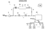
- FIG. 2 is a block diagram illustrating a normal power generation state of the fuel cell system according to the first embodiment.
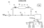
- FIG. 2 is a block diagram illustrating an air release state of the fuel cell system according to the first embodiment.
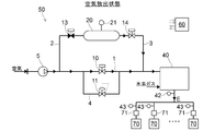
- FIG. 2 is a block diagram showing a state of air filling during operation of the fuel cell system according to the first embodiment;
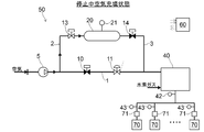
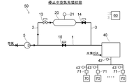
- FIG. 3 is a block diagram showing a stopped air filling state of the fuel cell system according to the first embodiment;
- FIG. 4 is a block diagram showing a normal power generation state of the fuel cell system according to the second embodiment.
- FIG. 4 is a block diagram showing an air release state of the fuel cell system according to the second embodiment.
- FIG. 4 is a block diagram illustrating a state of air filling during operation of the fuel cell system according to the second embodiment.
- FIG. 6 is a block diagram illustrating a normal power generation state of the fuel cell system according to the third embodiment.
- FIG. 6 is a block diagram showing an air release state of the fuel cell system according to the third embodiment.
- FIG. 6 is a block diagram illustrating a stopped-air charging state of the fuel cell system according to the third embodiment.
- FIG. 6 is a block diagram showing a stopped air filling state of the fuel cell system according to another embodiment.
- FIG. 10 is a block diagram showing an air release state of the fuel cell system according to the fourth embodiment.
- FIG. 10 is a block diagram showing an air filling state of the fuel cell system according to the fourth embodiment. Diagram showing a schematic configuration of a fuel cell ship
- the fuel cell system 50 includes a fuel cell 40 that generates power by an electrochemical reaction between hydrogen and air for power generation, and an operation control device 60 that controls power generation of the fuel cell 40 (control (An example of means).
- An air supply pump 5 that supplies air for power generation through the air supply path 1 to the cathode of the fuel cell 40 is provided upstream of the air supply path 1.
- the operation control device 60 controls the output of the air supply pump 5 such as operation / stop and discharge pressure.
- the pressure in the air supply path 1 may be set to a desired pressure value by controlling the opening of a pressure regulating valve provided on the air outlet side of the cathode of the fuel cell 40.
- the fuel cell system 50 of the present embodiment is mounted on a fuel cell ship 100 as a power source, as shown in FIG.
- the fuel cell ship 100 includes a fuel cell system 50, and a hydrogen cylinder 57 (an example of a fuel gas storage unit) that stores hydrogen (an example of a fuel gas) supplied to the fuel cell system 50.
- the electric power generated by the fuel cell system 50 is supplied to a plurality of electric loads 70 (see FIG. 1) provided in the ship, such as an electric motor 70A that rotationally drives the propeller 73 for propulsion.
- the on-board power load 70 includes ancillary equipment (not shown) such as lighting and a pump.
- the fuel cell system 50 can be installed in the ship so as to supply generated electric power to at least a part of the electric motor 70A and the incidental facilities.
- the electric power generated by the fuel cell system 50 can be supplied to only the electric motor 70A, only the auxiliary equipment, or both the electric motor 70A and the auxiliary equipment.
- Each of the plurality of power loads 70 connected to the fuel cell 40 is provided with an overcurrent open type circuit breaker 71 that automatically opens when an overcurrent occurs. That is, the power generated by the fuel cell 40 is supplied to each of the plurality of power loads 70 via each of the circuit breakers 71.
- the fuel cell system 50 is provided with overcurrent detectors 42 and 43 (overcurrent detection means) for detecting an overcurrent from the fuel cell 40 to the power load 70.
- the overcurrent detectors 42 and 43 use overcurrent when the current value of the generated power supplied from the fuel cell 40 to the plurality of power loads 70 exceeds a predetermined value and excessively increases. To detect. Then, the detection result is input to the operation control device 60.
- one fuel cell side overcurrent detector 42 provided on the fuel cell 40 side (an example of the fuel cell side overcurrent detection means) and the respective power load 70 side
- a plurality of provided power load side overcurrent detectors 43 (an example of power load side overcurrent detection means) are provided.
- the fuel cell side overcurrent detector 42 is configured to detect an excessive increase in the current value of the output power from the fuel cell 40 as an overcurrent. Accordingly, when a short circuit accident or the like occurs in any of the plurality of power loads 70, the occurrence of the short circuit accident or the like can be detected as an overcurrent by the common fuel cell side overcurrent detector 42. .
- the power load side overcurrent detector 43 is configured to detect an excessive increase in the current value of the power consumption of the power load 70 as an overcurrent. Accordingly, when a short circuit accident or the like occurs in any of the plurality of power loads 70, the occurrence of the short circuit accident or the like is performed by the individual power load side overcurrent detector 43 installed on the power load 70 side. The overcurrent can be detected quickly and reliably.
- the overcurrent detectors 42 and 43 may detect an overcurrent due to a short circuit accident or the like in a part of the power load 70. At that time, the operation control device 60 immediately executes disconnection of a part of the power load 70 in which the overcurrent has occurred, and executes protection coordination control for continuing supply of the generated power to other healthy power loads 70. It is configured to be.
- this protection coordination control when overcurrent is detected by the overcurrent detectors 42 and 43, the supply of hydrogen and air for power generation to the fuel cell 40 is performed by following an abrupt increase in the output.
- the volume is increased temporarily (eg, for 2 seconds) (eg, tripled).
- a current or power required for opening the circuit breaker 71 is secured.
- the circuit breakers 71 provided in some of the power loads 70 in which a short circuit accident or the like has occurred are effectively opened, and the power loads 70 are surely disconnected from the fuel cell 40.
- the air supply path 1 is provided with an air supply valve 10 that can open and close the air supply path 1. Further, on the downstream side of the air supply valve 10 in the air supply path 1, a pressure regulating valve 11 (an example of a pressure reducing unit) that reduces the air supplied from the upstream side to a predetermined set supply pressure and flows the air to the downstream side is provided. ing.
- the pressure regulating valve 11 functions as a pressure reducing unit that can reduce the pressure of the compressed air discharged from the air supply pump 5 to a predetermined set supply pressure and supply the compressed air to the fuel cell 40 as power generation air.
- An air tank 20 (an example of an air storage unit) that stores compressed air is provided in flow paths 2 and 3 that are provided in such a manner as to bypass the air supply valve 10 and the pressure regulating valve 11 that are arranged in series with the air supply path 1.
- the flow paths 2 and 3 include an air filling path 2 that connects the upstream side of the air supply valve 10 in the air supply path 1 and the primary side of the air tank 20, and a control section between the secondary side of the air tank 20 and the air supply path 1.
- the air discharge passage 3 connects the downstream side of the pressure valve 11.
- the capacity of the air tank 20 is determined by the amount of the power generation air supplied to the fuel cell 40 when the compressed air stored in the air tank 20 at a predetermined filling pressure is discharged to the air supply path 1. Is set to a capacity that can be increased at a desired time (for example, 2 seconds) at a desired rate (for example, 3 times).
- the air discharge passage 3 is provided with an air discharge valve 14 that can open and close the air discharge passage 3.
- the air release valve 14 can release the compressed air stored in the air tank 20 to the fuel cell 40 as power generation air through the air release path 3 and the air supply path 1 in accordance with the valve opening operation.
- a check valve (not shown) for preventing backflow of the air discharged from the air discharge passage 3 is provided upstream of the junction of the air supply passage 1 and the air discharge passage 3. ) Can be appropriately set.
- the air filling path 2 is provided with an air filling valve 13 that can open and close the air filling path 2.
- the air filling path 2 serves as a flow path for introducing the compressed air discharged from the air supply pump 5 to the air tank 20 with the opening operation of the air filling valve 13.
- the air filling path 2 and the air filling valve 13 together with the air supply pump 5 function as air filling means capable of filling the air tank 20 with compressed air.
- the air tank 20 is provided with a pressure sensor 21 for detecting the internal pressure of the air tank 20, and the detection result is input to the operation control device 60.
- the operation state of the air supply pump 5 is changed to the normal power generation state (see FIG. 1), the air release state (see FIG. 2), and the operation by the operation control by the operation control device 60.
- the state is switched from the medium air filling state (see FIG. 3) and the stopped air filling state (see FIG. 4) to a selected state.
- each state will be described in detail.
- the normal power generation state shown in FIG. 1 is a state in which power generation air is supplied from the air supply pump 5 to the fuel cell 40 and the fuel cell 40 performs a power generation operation when the protection coordination control is not executed.
- the discharge pressure of the air supply pump 5 is set to the set supply pressure of the power generation air to be supplied to the fuel cell 40.
- the air filling valve 13 and the air discharging valve 14 are closed, and the air supply valve 10 is opened.
- the compressed air of the set supply pressure discharged from the air supply pump 5 is supplied to the pressure regulating valve 11 provided in the air supply path 1 through the air supply valve 10 and passes through the pressure regulating valve 11 with the set supply pressure.
- the air tank 20 stores compressed air having a predetermined set filling pressure higher than the set supply pressure.
- the air release state shown in FIG. 2 is a state in which a predetermined air release process has been performed in the above-described protection cooperative control to temporarily increase the supply amount of power generation air to the fuel cell 40.
- the air release valve 14 is opened.
- the compressed air of the set filling pressure filled in the air tank 20 is discharged through the air discharge passage 3 between the pressure regulating valve 11 and the fuel cell 40 in the air supply passage 1.
- Air filling during operation In the air filling state during operation shown in FIG. 3, the compressed air is filled into the air tank 20 prior to the execution of the above-described air release processing during the power generation operation in which the power supply air is supplied from the air supply pump 5 to the fuel cell 40.
- the in-operation air filling process (an example of the air filling process) is performed.
- the air supply valve 10 In the air filling process during operation, the air supply valve 10 is opened, and the air supply valve 13 is opened while increasing the rotation speed of the air supply pump 5 to increase the discharge flow rate of the air supply pump 5. Performed in form.
- the pressure regulating valve 11 functions as a pressure reducing unit that limits the flow rate of the air supplied to the fuel cell 40 and reduces the pressure of the air to a predetermined set supply pressure. Therefore, the discharge pressure of the air supply pump 5 increases with an increase in the discharge flow rate, and as a result, the discharge pressure is set to a predetermined set filling pressure higher than the set supply pressure of the pressure regulating valve 11.
- valves in a closed state are represented by black, and valves in an open state are represented by white.
- a detailed description of the same configuration as the above-described embodiment may be omitted.
- the air supply path 1 is provided with an air supply valve 10 that can open and close the air supply path 1.
- a pressure regulating valve 11 (an example of a pressure reducing unit) is provided in a bypass passage 4 which bypasses the air supply valve 10 to reduce the air supplied from the upstream side to a predetermined set supply pressure and flow the air to the downstream side. ) Is provided. That is, the pressure regulating valve 11 functions as a pressure reducing unit that can reduce the compressed air discharged from the air supply pump 5 to a predetermined set supply pressure and supply the compressed air to the fuel cell 40 as power generation air.
- the pressure regulating valve 11 and the pressure regulating valve 11 are connected in order to reliably stop the flow of air in the bypass 4.
- an on-off valve provided in the bypass passage 4 may be closed.
- An air tank 20 (an example of an air storage unit) is provided in the flow paths 2 and 3 provided in such a manner as to bypass the air supply valve 10 and the pressure regulating valve 11 arranged in parallel with the air supply path 1. .
- the air charging path 2 is provided with an air charging valve 13, and the air discharging path 3 is provided with an air discharging valve 14.
- a check valve (not shown) for preventing backflow of the air discharged from the air discharge passage 3 is provided upstream of the junction of the air supply passage 1 and the air discharge passage 3. ) Can be appropriately set.
- the operation state of the air supply pump 5 is changed to the normal power generation state (see FIG. 5), the air release state (see FIG. 6), and the air supply state by the operation control by the operation control device 60. , Is switched from the air filling state during operation (see FIG. 7) to a state selected.
- each state will be described in detail.
- the normal power generation state shown in FIG. 5 is a state in which when the protection coordination control is not executed, the air supply pump 5 supplies air for power generation to the fuel cell 40 and the fuel cell 40 performs power generation operation.
- the discharge pressure of the air supply pump 5 is set to the set supply pressure of the power generation air to be supplied to the fuel cell 40.
- the air filling valve 13 and the air discharging valve 14 are closed, and the air supply valve 10 is opened. Then, the compressed air of the set supply pressure discharged from the air supply pump 5 is supplied to the fuel cell 40 through the air supply valve 10 and used for power generation in the fuel cell 40.
- the air discharged from the air supply pump 5 is not depressurized by the pressure control valve 11 as a pressure reducing unit, and is supplied to the fuel cell 40 through the pressure control valve 11 and the air supply valve 10. Supplied. Therefore, since the discharge pressure of the air supply pump 5 at this time is set to a relatively low set supply pressure, consumption of operating energy of the air supply pump 5 is suppressed.
- the air tank 20 stores compressed air having a predetermined set filling pressure higher than the set supply pressure.
- the pressure regulating valve 11 or an on-off valve provided in the bypass 4 together with the pressure regulating valve 11 is closed, and air is supplied to the fuel cell 40 only through the air supply valve 10. May be configured to be supplied.
- the air release state shown in FIG. 6 is a state in which a predetermined air release process has been performed in the above-described protection cooperative control to temporarily increase the supply amount of the power generation air to the fuel cell 40.
- the air release valve 14 is opened.
- the compressed air filled in the air tank 20 with the relatively high set filling pressure is discharged through the air discharge passage 3 between the air supply valve 10 and the fuel cell 40 in the air supply passage 1.
- Air filling during operation In the air filling state during operation shown in FIG. 7, during the power generation operation in which the power supply air is supplied from the air supply pump 5 to the fuel cell 40, the air tank 20 is filled with the compressed air prior to the execution of the above-described air release processing. In this state, the in-operation air filling process (an example of the air filling process) is performed.
- the air filling process during the operation is performed by closing the air supply valve 10 and increasing the rotation speed of the discharge pressure of the air supply pump 5 to increase the discharge flow rate of the air supply pump 5 while the air supply valve 13 is being operated. It is executed in the form of opening the valve.
- the pressure regulating valve 11 functions as a pressure reducing unit that limits the flow rate of the air supplied to the fuel cell 40 and reduces the pressure of the air to a predetermined set supply pressure. Therefore, the discharge pressure of the air supply pump 5 increases with an increase in the discharge flow rate, and as a result, is set to a predetermined set filling pressure higher than the set supply pressure of the pressure regulating valve 11.
- valves in a closed state are represented by black, and valves in an open state are represented by white.
- a detailed description of the same configuration as the above-described embodiment may be omitted.
- the air supply path 1 is provided with an air supply valve 10 that can open and close the air supply path 1.
- An air tank 20 (an example of an air storage unit) is provided in the flow paths 2 and 3 provided in such a manner as to bypass the air supply valve 10 arranged in the air supply path 1.
- the air charging path 2 is provided with an air charging valve 13
- the air discharging path 3 is provided with an air discharging valve 14.
- a check valve (not shown) for preventing backflow of the air discharged from the air discharge passage 3 is provided upstream of the junction of the air supply passage 1 and the air discharge passage 3. ) Can be appropriately set.
- the operation state of the air supply pump 5 is changed to the normal power generation state (see FIG. 8), the air discharge state (see FIG. 9), and the air supply state by the operation control by the operation control device 60.
- the state is switched from the stopped air filling state (see FIG. 10) to the selected state.
- each state will be described in detail.
- the normal power generation state shown in FIG. 8 is a state in which when the protection coordination control is not executed, the air supply pump 5 supplies air for power generation to the fuel cell 40 and the fuel cell 40 performs power generation operation.
- the discharge pressure of the air supply pump 5 is set to the set supply pressure of the power generation air to be supplied to the fuel cell 40.
- the air filling valve 13 and the air discharging valve 14 are closed, and the air supply valve 10 is opened. Then, the compressed air of the set supply pressure discharged from the air supply pump 5 is supplied to the fuel cell 40 through the air supply valve 10 and used for power generation in the fuel cell 40.
- the air tank 20 stores compressed air having a predetermined set filling pressure higher than the set supply pressure.
- the air release state shown in FIG. 9 is a state in which a predetermined air release process has been executed in the above-described protection cooperative control to temporarily increase the supply amount of the power generation air to the fuel cell 40.
- the air release valve 14 is opened.
- the compressed air of the set filling pressure filled in the air tank 20 is discharged through the air discharge passage 3 between the air supply valve 10 and the fuel cell 40 in the air supply passage 1.
- FIG. 11 a plurality of air tanks 20 may be provided in parallel.
- an air release valve 14 and an air filling valve 13 are provided in each of the plurality of air tanks 20.
- the air release valves 14 provided in some of the air tanks 20 selected from the plurality of air tanks 20 are opened to release the compressed air stored in the some of the air tanks 20. It is discharged to the air supply path 1.
- the air filling process during stoppage as shown in FIG.
- valves in a closed state are represented by black, and valves in an open state are represented by white.
- a detailed description of the same configuration as the above-described embodiment may be omitted.
- the air supply path 1 is provided with an air supply valve 10 that can open and close the air supply path 1.
- an air tank 20 (an example of an air storage unit) is provided.
- the air charging path 2 is provided with an air charging valve 13
- the air discharging path 3 is provided with an air discharging valve 14.
- a check valve (not shown) for preventing backflow of the air discharged from the air discharge passage 3 is provided upstream of the junction of the air supply passage 1 and the air discharge passage 3. ) Can be appropriately set. In this case, the air supply valve 10 may be omitted.
- the air filling path 2 serves as a flow path for introducing the compressed air discharged from the filling air supply pump 15 into the air tank 20 with the opening operation of the air filling valve 13.
- the air filling path 2 and the air filling valve 13 together with the filling air supply pump 15 function as air filling means capable of filling the air tank 20 with compressed air.
- the operation state of the air supply pump 5 and the filling air supply pump 15 is changed to the normal power generation state (see FIG. 12) and the air release state by the operation control by the operation control device 60. (See FIG. 13) and a state selected from the air-filled state (see FIG. 14).
- each state will be described in detail.
- the normal power generation state shown in FIG. 12 is a state in which when the protection coordination control is not being executed, the air supply pump 5 supplies air for power generation to the fuel cell 40 and the fuel cell 40 performs power generation operation.
- the discharge pressure of the air supply pump 5 is set to the set supply pressure of the power generation air to be supplied to the fuel cell 40.
- the filling air supply pump 15 is stopped, the air filling valve 13 and the air release valve 14 are closed, and the air supply valve 10 is opened. Then, the compressed air of the set supply pressure discharged from the air supply pump 5 is supplied to the fuel cell 40 through the air supply valve 10 and used for power generation in the fuel cell 40.
- the air tank 20 stores compressed air having a predetermined set filling pressure higher than the set supply pressure.
- the air release state shown in FIG. 13 is a state in which a predetermined air release process is executed in the above-described protection cooperative control to temporarily increase the supply amount of the power generation air to the fuel cell 40.
- the air release valve 14 is opened.
- the compressed air of the set filling pressure filled in the air tank 20 is discharged through the air discharge passage 3 between the air supply valve 10 and the fuel cell 40 in the air supply passage 1.
- the air filling state shown in FIG. 14 is a state in which an air filling process (an example of an air filling process) for filling the air tank 20 with compressed air is performed prior to the execution of the above-described air release process.
- an air filling process an example of an air filling process
- the air supply pump 5 When the air supply pump 5 is operated and the air supply valve 10 is opened in this air-filled state, the supply of air for power generation to the fuel cell 40 is continued, and conversely, the air supply pump 5 is stopped.
- the air supply valve 10 is closed, the supply of the power generation air to the fuel cell 40 is stopped.
- the operation of the filling air supply pump 15 is started, and the air filling valve 13 is opened while the discharge pressure of the filling air supply pump 15 is set to a predetermined set filling pressure higher than the set supply pressure. It is performed in the form of a valve. Then, all of the air at the set filling pressure discharged from the air supply pump 5 is supplied to the air tank 20 through the air filling path 2 and stored in the air tank 20.
- the air filling valve 13 is closed and the operation of the filling air supply pump 15 is stopped. The process ends.
- the air supply pump 5 continues to supply the power generation air to the fuel cell 40
- the air supply valve 10 is maintained in the open state, and the normal power generation state described above is established. The power generation in the fuel cell 40 is continued.
- the present invention is not limited to such a configuration, and other transportation machines or energy may be used.
- the present invention can also be applied to a fuel cell system mounted on a device.
- the air storage unit that stores the compressed air is configured as the air tank 20, but the mode of the air storage unit is not limited to the tank, and any air storage unit that has a space that can store the compressed air is provided. good.
- the decompression unit capable of decompressing the compressed air discharged from the air supply pump 5 to a predetermined set supply pressure and supplying the decompressed air to the fuel cell 40 as power generation air is provided.
- An orifice (throttle section) that narrows the flow path section instead of the pressure regulating valve 11 May be provided as a decompression unit.
- both the fuel cell side overcurrent detector 42 and the plurality of power load side overcurrent detectors 43 are provided as the overcurrent detectors 42 and 43, but one of them may be omitted. Absent.
- the present invention is mainly provided in a fuel cell ship or the like, and when supplying generated power of a fuel cell to a plurality of power loads via respective circuit breakers, performs protection cooperative control when an overcurrent is detected. It can be suitably used for a fuel cell system to be executed.
- Air supply path 2 Air filling path 3 Air discharge path 4 Bypass path 5
- Air supply pump 10 Air supply valve 11
- Pressure regulating valve (pressure reducing section) 13 air filling valve 14
- air release valve 20 air tank (air storage section) 40 fuel cell
- fuel cell side overcurrent detector (fuel cell side overcurrent detection means) 43 power load side overcurrent detector (power load side overcurrent detection means)
- fuel cell system 60 operation control device (control means) 70 Electric load 70A Electric motor (electric load) 71 Circuit breaker 100 Fuel cell ship
Landscapes
- Engineering & Computer Science (AREA)
- Power Engineering (AREA)
- Sustainable Development (AREA)
- Sustainable Energy (AREA)
- Life Sciences & Earth Sciences (AREA)
- Transportation (AREA)
- Mechanical Engineering (AREA)
- Manufacturing & Machinery (AREA)
- Chemical & Material Sciences (AREA)
- Chemical Kinetics & Catalysis (AREA)
- Electrochemistry (AREA)
- General Chemical & Material Sciences (AREA)
- Fuel Cell (AREA)
- Electric Propulsion And Braking For Vehicles (AREA)
Abstract
燃料電池の発電電力を複数の電力負荷に対して夫々の遮断器を介して供給するにあたり、過電流が検出されたときに保護協調制御を実行する燃料電池システムにおいて、短絡事故等が発生した電力負荷を確実に燃料電池から切り離しながら、空気枯れに起因する燃料電池の性能低下や損傷を抑制できる技術を提供する。圧縮空気を貯留する空気貯留部(20)を備えると共に、当該空気貯留部(20)に貯留されている圧縮空気を発電用空気として燃料電池(40)に放出可能な空気放出弁(14)を備え、制御手段(60)が、保護協調制御において、空気放出弁(14)を開弁させて空気貯留部(20)に貯留されている圧縮空気を空気供給路(1)に放出させる空気放出処理を実行する。
Description
本発明は、燃料電池の発電電力を複数の電力負荷に対して夫々の遮断器を介して供給するにあたり、過電流が検出されたときに保護協調制御を実行する燃料電池システム、及びそれを備えた燃料電池船に関する。
燃料電池システムでは、燃料電池から発電電力が供給される一部の電力負荷で短絡事故等が発生した際に、その電力負荷を速やかに切り離して、健全な他の電力負荷に対する発電電力の供給を継続するための保護協調制御を実行することがある。特に船舶に設置される燃料電池システムでは、動力源となる燃料電池を確実に保護するべく、信頼性の高い保護協調制御の実行が求められる。
かかる保護協調制御では、一部の電力負荷での短絡事故等に起因して燃料電池の出力が急増することで過電流が検出されると、燃料電池への発電用燃料及び発電用空気の供給量が一時的に増加される。すると、急増する出力に加えて遮断器の開放に必要な電流又は電力を確保することができるので、短絡事故等が発生した電力負荷の遮断器を有効に開放させて、当該電力負荷を燃料電池から確実に切り離すことができる。
一方、従来の燃料電池システムとして、燃料電池の出力の増加に追従させて、空気供給ポンプから燃料電池への発電用空気の供給量を増加させるように構成されたものが知られている(例えば、特許文献1を参照。)。かかる特許文献1に記載の燃料電池システムでは、出力の増加時において、空気供給ポンプから燃料電池に至る流路を、発電運転時の空気供給路から、当該空気供給路よりも大容量のバイパス路に切り替えることで、燃料電池への発電用空気の供給量を増加させている。
空気供給ポンプから発電用空気を燃料電池に供給する燃料電池システムにおいて、保護協調制御の実行時において、出力の急激な増加に対して燃料電池への発電用空気の供給量を迅速に追従させて増加させることができない場合がある。例えば、上述の特許文献1に記載の技術では、通常の出力の増加に対しては発電用空気の供給量を追従させて増加できるものの、短絡事故等に起因する急激な出力の増加に対しては、それに追従させて発電用空気の供給量を急激に増加させることができない。
このように保護協調制御の実行時において燃料電池への発電用空気の供給量を急激に増加させることができない場合には、短絡事故等が発生した電力負荷の遮断器を開放させるための電流又は電力を確保できずに、当該電力負荷を燃料電池から切り離すことができないという問題が生じる。更には、カソード電極において空気が消費尽くされる所謂空気枯れが発生して、燃料電池の性能低下や損傷を招く虞がある。
このように保護協調制御の実行時において燃料電池への発電用空気の供給量を急激に増加させることができない場合には、短絡事故等が発生した電力負荷の遮断器を開放させるための電流又は電力を確保できずに、当該電力負荷を燃料電池から切り離すことができないという問題が生じる。更には、カソード電極において空気が消費尽くされる所謂空気枯れが発生して、燃料電池の性能低下や損傷を招く虞がある。
この実情に鑑み、本発明の主たる課題は、燃料電池の発電電力を複数の電力負荷に対して夫々の遮断器を介して供給するにあたり、過電流が検出されたときに保護協調制御を実行する燃料電池システムにおいて、短絡事故等が発生した電力負荷を確実に燃料電池から切り離しながら、空気枯れに起因する燃料電池の性能低下や損傷を抑制できる技術を提供する点にある。
本発明の第1特徴構成は、複数の電力負荷に対して夫々の遮断器を介して発電電力を供給する燃料電池と、
前記燃料電池に空気供給路を通じて発電用空気を供給する空気供給ポンプと、
前記燃料電池の発電制御を行う制御手段と、
過電流を検出する過電流検出手段と、を備え、
前記制御手段が、前記過電流検出手段で過電流を検出したときに前記燃料電池への発電用空気の供給量を一時的に増加させる保護協調制御を実行する燃料電池システムであって、
圧縮空気を貯留する空気貯留部を備えると共に、当該空気貯留部に貯留されている圧縮空気を前記発電用空気として前記燃料電池に放出可能な空気放出弁を備え、
前記制御手段が、前記保護協調制御において、前記空気放出弁を開弁させて前記空気貯留部に貯留されている圧縮空気を前記空気供給路に放出させる空気放出処理を実行する点にある。
前記燃料電池に空気供給路を通じて発電用空気を供給する空気供給ポンプと、
前記燃料電池の発電制御を行う制御手段と、
過電流を検出する過電流検出手段と、を備え、
前記制御手段が、前記過電流検出手段で過電流を検出したときに前記燃料電池への発電用空気の供給量を一時的に増加させる保護協調制御を実行する燃料電池システムであって、
圧縮空気を貯留する空気貯留部を備えると共に、当該空気貯留部に貯留されている圧縮空気を前記発電用空気として前記燃料電池に放出可能な空気放出弁を備え、
前記制御手段が、前記保護協調制御において、前記空気放出弁を開弁させて前記空気貯留部に貯留されている圧縮空気を前記空気供給路に放出させる空気放出処理を実行する点にある。
また、本発明に係る燃料電池船の特徴構成は、本発明に係る燃料電池システムと、
前記燃料電池システムに供給される燃料ガスを貯留する燃料ガス貯留部と、を備え、
前記燃料電池システムの発電電力を船内における複数の電力負荷に対して夫々の遮断器を介して供給する点にある。
前記燃料電池システムに供給される燃料ガスを貯留する燃料ガス貯留部と、を備え、
前記燃料電池システムの発電電力を船内における複数の電力負荷に対して夫々の遮断器を介して供給する点にある。
本構成によれば、信頼性の高い保護協調制御の実行が求められる燃料電池船等に搭載される燃料電池システムにおいて、圧縮空気を貯留する空気貯留部と、当該空気貯留部に貯留されている圧縮空気を発電用空気として燃料電池に放出可能な空気放出弁とを備えることにより、空気放出弁の開弁操作に伴って空気貯留部に貯留されている圧縮空気を燃料電池に通じる空気供給路に迅速に放出させる空気放出処理が実行可能となる。
そして、一部の電力負荷での短絡事故等に起因して燃料電池の出力が急増して燃料電池から電力負荷への過電流が検出された際に燃料電池での発電を継続するために実行される保護協調制御において、上記のような空気放出処理が実行されるので、出力の急激な増加に対して燃料電池への発電用空気の供給量を迅速に追従させて一時的に増加させることができる。このことにより、カソード電極の空気枯れを回避しながら、短絡事故等が発生した電力負荷の遮断器を開放させるための電流又は電力を確保することができる。
そして、一部の電力負荷での短絡事故等に起因して燃料電池の出力が急増して燃料電池から電力負荷への過電流が検出された際に燃料電池での発電を継続するために実行される保護協調制御において、上記のような空気放出処理が実行されるので、出力の急激な増加に対して燃料電池への発電用空気の供給量を迅速に追従させて一時的に増加させることができる。このことにより、カソード電極の空気枯れを回避しながら、短絡事故等が発生した電力負荷の遮断器を開放させるための電流又は電力を確保することができる。
従って、本発明により、燃料電池の発電電力を複数の電力負荷に対して夫々の遮断器を介して供給するにあたり、過電流が検出されたときに保護協調制御を実行する燃料電池システムにおいて、短絡事故等が発生した電力負荷を確実に燃料電池から切り離しながら、空気枯れに起因する燃料電池の性能低下や損傷を抑制できる技術を提供することができる。
本発明の第2特徴構成は、上記第1特徴構成に加えて、前記空気貯留部に圧縮空気を充填可能な空気充填手段を備え、
前記制御手段が、前記空気放出処理の実行に先立って前記空気充填手段を作動させて前記空気貯留部に圧縮空気を充填する空気充填処理を実行する点にある。
前記制御手段が、前記空気放出処理の実行に先立って前記空気充填手段を作動させて前記空気貯留部に圧縮空気を充填する空気充填処理を実行する点にある。
本構成によれば、上記空気充填手段を備えることにより、当該空気充填手段を作動させて空気貯留部に圧縮空気を充填する空気充填処理が実行可能となる。
そして、制御手段により、空気放出処理の実行に先立って上記のような空気充填処理を実行するので、空気貯留部に貯留されている圧縮空気を空気供給路に放出させる空気放出処理の実行時には必ず空気貯留手段に適切に圧縮空気が貯留されて状態とすることができる。
そして、制御手段により、空気放出処理の実行に先立って上記のような空気充填処理を実行するので、空気貯留部に貯留されている圧縮空気を空気供給路に放出させる空気放出処理の実行時には必ず空気貯留手段に適切に圧縮空気が貯留されて状態とすることができる。
本発明の第3特徴構成は、上記第2特徴構成に加えて、前記空気供給ポンプから吐出された圧縮空気を所定の設定供給圧に減圧して前記発電用空気として前記燃料電池に供給可能な減圧部を備えると共に、
前記空気充填手段が、前記空気供給ポンプから吐出された圧縮空気を前記空気貯留部に導入する空気充填路と、前記空気充填路に設けられて当該空気充填路を開閉可能な空気充填弁とで構成され、
前記制御手段が、前記空気供給ポンプの吐出圧を前記設定供給圧よりも高い設定充填圧に設定しながら前記空気充填弁を開弁させる形態で前記空気充填処理を実行する点にある。
前記空気充填手段が、前記空気供給ポンプから吐出された圧縮空気を前記空気貯留部に導入する空気充填路と、前記空気充填路に設けられて当該空気充填路を開閉可能な空気充填弁とで構成され、
前記制御手段が、前記空気供給ポンプの吐出圧を前記設定供給圧よりも高い設定充填圧に設定しながら前記空気充填弁を開弁させる形態で前記空気充填処理を実行する点にある。
本構成によれば、空気充填弁を開弁させる形態で、空気供給ポンプから吐出された設定充填圧の圧縮空気を空気充填路の空気充填弁を通じて空気貯留部に充填する空気充填処理を実行することができる。この場合、空気供給ポンプから吐出された圧縮空気は、燃料電池に供給すべき発電用空気の設定供給圧よりも高い設定充填圧に設定されているため、調圧弁やオリフィス等の上記減圧部を備えることで、その圧縮空気を設定供給圧に減圧して発電用空気として燃料電池に供給することができる。
従って、空気供給ポンプから燃料電池に発電用空気を供給して当該燃料電池で発電を行う発電運転を継続しながら、共通の空気供給ポンプを利用して空気貯留部に圧縮空気を充填する空気充填処理を実行することができる。
従って、空気供給ポンプから燃料電池に発電用空気を供給して当該燃料電池で発電を行う発電運転を継続しながら、共通の空気供給ポンプを利用して空気貯留部に圧縮空気を充填する空気充填処理を実行することができる。
本発明の第4特徴構成は、上記第3特徴構成に加えて、前記減圧部が、前記空気供給路に設けられている点にある。
本構成によれば、発電運転時において空気充填弁が閉弁されて空気充填処理が実行されないときであっても、空気供給ポンプでの吐出圧を設定充填圧に維持して、空気供給ポンプから吐出される圧縮空気を空気供給路に設けられた減圧部により設定供給圧に減圧して発電用空気として燃料電池に供給することができる。
そして、この状態から空気充填弁を開弁させるだけで、発電運転を継続しながら空気充填処理を実行することができる。
そして、この状態から空気充填弁を開弁させるだけで、発電運転を継続しながら空気充填処理を実行することができる。
本発明の第5特徴構成は、上記第3特徴構成に加えて、前記空気供給路に設けられて当該空気供給路を開閉可能な空気供給弁と、
前記空気供給路における前記空気供給弁をバイパスするバイパス路と、を備え、
前記減圧部が、前記バイパス路に設けられており、
前記制御手段が、前記空気供給弁を閉弁させると共に前記空気充填弁を開弁させる形態で前記空気充填処理を実行する点にある。
前記空気供給路における前記空気供給弁をバイパスするバイパス路と、を備え、
前記減圧部が、前記バイパス路に設けられており、
前記制御手段が、前記空気供給弁を閉弁させると共に前記空気充填弁を開弁させる形態で前記空気充填処理を実行する点にある。
本構成によれば、発電運転時において空気充填弁が閉弁されて空気充填処理が実行されないときには、空気供給ポンプの吐出圧を比較的低い設定供給圧に設定しながら、空気供給路に設けられた空気供給弁を開弁して、空気供給ポンプから吐出された空気を、減圧部で減圧させることなく、空気供給弁と減圧部とを通じて発電用空気として燃料電池に供給することができる。よって、この際の空気供給ポンプの作動エネルギーの消費を抑制することができる。
そして、この状態から空気供給ポンプの吐出圧を設定充填圧に設定し、空気供給弁を閉弁させると共に空気充填弁を開弁させる形態で、発電運転を継続しながら空気充填処理を実行することができる。即ち、空気供給ポンプから吐出される設定充填圧の圧縮空気を、バイパス路に設けられた減圧部により設定供給圧に減圧して発電用空気として燃料電池に供給することができる。同時に、空気供給ポンプから吐出される設定充填圧の圧縮空気を、空気充填路の空気充填弁を通じて空気貯留部に充填することができる。
そして、この状態から空気供給ポンプの吐出圧を設定充填圧に設定し、空気供給弁を閉弁させると共に空気充填弁を開弁させる形態で、発電運転を継続しながら空気充填処理を実行することができる。即ち、空気供給ポンプから吐出される設定充填圧の圧縮空気を、バイパス路に設けられた減圧部により設定供給圧に減圧して発電用空気として燃料電池に供給することができる。同時に、空気供給ポンプから吐出される設定充填圧の圧縮空気を、空気充填路の空気充填弁を通じて空気貯留部に充填することができる。
本発明の第6特徴構成は、上記第2特徴構成に加えて、前記空気供給路に設けられて当該空気供給路を開閉可能な空気供給弁を備え、
前記空気充填手段が、前記空気供給ポンプから吐出された圧縮空気を前記空気貯留部に導入する空気充填路と、前記空気充填路に設けられて当該空気充填路を開閉可能な空気充填弁とで構成され、
前記制御手段が、前記空気供給ポンプから前記燃料電池への発電用空気の供給を行う発電運転時に、前記空気供給ポンプの吐出圧を所定の設定供給圧に設定すると共に、前記燃料電池への発電用空気の供給を停止する発電停止時に、前記空気供給ポンプの吐出圧を前記設定供給圧よりも高い設定充填圧に設定しながら前記空気充填弁を開弁させる形態で前記空気充填処理を実行する点にある。
前記空気充填手段が、前記空気供給ポンプから吐出された圧縮空気を前記空気貯留部に導入する空気充填路と、前記空気充填路に設けられて当該空気充填路を開閉可能な空気充填弁とで構成され、
前記制御手段が、前記空気供給ポンプから前記燃料電池への発電用空気の供給を行う発電運転時に、前記空気供給ポンプの吐出圧を所定の設定供給圧に設定すると共に、前記燃料電池への発電用空気の供給を停止する発電停止時に、前記空気供給ポンプの吐出圧を前記設定供給圧よりも高い設定充填圧に設定しながら前記空気充填弁を開弁させる形態で前記空気充填処理を実行する点にある。
本構成によれば、発電停止時において、空気供給弁を閉弁せると共に空気充填弁を開弁させる形態で空気充填処理を実行して、空気供給ポンプから吐出された設定充填圧の圧縮空気を空気充填路の空気充填弁を通じて空気貯留部に充填する空気充填処理を実行することができる。
一方、発電運転時において、空気供給ポンプの吐出圧を比較的低い設定供給圧に設定しながら、空気充填弁を閉弁すると共に空気供給路に設けられた空気供給弁を開弁して、空気供給ポンプから吐出された設定供給圧の空気を、空気供給路を通じて発電用空気として燃料電池に供給することができる。よって、この際の空気供給ポンプの作動エネルギーの消費を抑制することができる。
一方、発電運転時において、空気供給ポンプの吐出圧を比較的低い設定供給圧に設定しながら、空気充填弁を閉弁すると共に空気供給路に設けられた空気供給弁を開弁して、空気供給ポンプから吐出された設定供給圧の空気を、空気供給路を通じて発電用空気として燃料電池に供給することができる。よって、この際の空気供給ポンプの作動エネルギーの消費を抑制することができる。
本発明の第7特徴構成は、上記第1乃至第6特徴構成の何れかに加えて、前記空気貯留部の複数を並列状態で備えると共に、当該複数の空気貯留部の夫々に前記空気放出弁を備え、
前記制御手段が、前記空気放出処理において、前記複数の空気貯留部から選択される一部の空気貯留部に備えられた空気放出弁を開弁させて当該一部の空気貯留部に貯留されている圧縮空気を前記空気供給路に放出させる点にある。
前記制御手段が、前記空気放出処理において、前記複数の空気貯留部から選択される一部の空気貯留部に備えられた空気放出弁を開弁させて当該一部の空気貯留部に貯留されている圧縮空気を前記空気供給路に放出させる点にある。
本構成によれば、一部の電力負荷での短絡事故等に起因して実行される保護協調制御において、一部の空気放出弁を開弁させて当該一部の空気貯留部が備えられた一部の空気貯留部に貯留されている圧縮空気を空気供給路に放出させる空気放出処理を実行した直後であっても、他部の空気貯留部には圧縮空気が貯留された状態となる。従って、その空気放出処理の実行直後に他の電力負荷での短絡事故等に起因して保護協調制御を実行する際に、その他部の空気貯留部に備えられた空気放出弁を開弁させて当該他部の空気貯留部が備えられた他部の空気貯留部に貯留されている圧縮空気を空気供給路に放出させる空気放出処理を確実且つ瞬時に実行することができる。
本発明の第8特徴構成は、上記第1乃至第7特徴構成の何れかに加えて、前記過電流検出手段として、前記燃料電池からの出力電力の電流値の過剰な上昇を前記過電流として検出する燃料電池側過電流検出手段を備えた点にある。
本構成によれば、複数の電力負荷の何れかで短絡事故等が発生した場合に、燃料電池側に設置された共通の燃料電池側電流検出手段によって、当該短絡事故等の発生を過電流として検出することができる。従って、過電流検出手段の設置が少なくて済むので、システムの低廉化を図ることができる。
本発明の第9特徴構成は、上記第1乃至第8特徴構成の何れかに加えて、前記過電流検出手段として、前記複数の電力負荷の夫々に設けられ、当該電力負荷の消費電力の電流値の過剰な上昇を前記過電流として検出する電力負荷側過電流検出手段を備えた点にある。
本構成によれば、複数の電力負荷の何れかで短絡事故等が発生した場合に、その電力負荷側に設置された個別の電力負荷側過電流検出手段によって、当該短絡事故等の発生を迅速且つ確実に過電流として検出することができる。従って、安全性及び信頼性が高いシステムを構築することができる。
〔第1実施形態〕
本発明の第1実施形態について、図1~図4等に基づいて説明する。尚、各図において、閉弁状態にある弁は黒塗りで表し、開弁状態にある弁は白抜きで表している。
図1~図4に示す本実施形態の燃料電池システム50は、水素と発電用空気との電気化学反応により発電を行う燃料電池40と、燃料電池40の発電制御を行う運転制御装置60(制御手段の一例)等とを備えて構成されている。
空気供給路1の上流側には、燃料電池40のカソードに空気供給路1を通じて発電用空気を供給する空気供給ポンプ5が設けられている。この空気供給ポンプ5の運転・停止や吐出圧等の出力が運転制御装置60により制御される。尚、図示は省略するが、燃料電池40のカソードの空気出口側に設置した調圧弁の開度を制御して、空気供給路1内の圧力を所望の圧力値に設定する構成としても良い。
本発明の第1実施形態について、図1~図4等に基づいて説明する。尚、各図において、閉弁状態にある弁は黒塗りで表し、開弁状態にある弁は白抜きで表している。
図1~図4に示す本実施形態の燃料電池システム50は、水素と発電用空気との電気化学反応により発電を行う燃料電池40と、燃料電池40の発電制御を行う運転制御装置60(制御手段の一例)等とを備えて構成されている。
空気供給路1の上流側には、燃料電池40のカソードに空気供給路1を通じて発電用空気を供給する空気供給ポンプ5が設けられている。この空気供給ポンプ5の運転・停止や吐出圧等の出力が運転制御装置60により制御される。尚、図示は省略するが、燃料電池40のカソードの空気出口側に設置した調圧弁の開度を制御して、空気供給路1内の圧力を所望の圧力値に設定する構成としても良い。
尚、本実施形態の燃料電池システム50は、図15に示すように、燃料電池船100に動力源として搭載されている。かかる燃料電池船100は、燃料電池システム50と、燃料電池システム50に供給される水素(燃料ガスの一例)を貯留する水素ボンベ57(燃料ガス貯留部の一例)と、を備える。更に、推進用プロペラ73を回転駆動する電動モータ70A等の船内に設けられた複数の電力負荷70(図1参照)に対して燃料電池システム50の発電電力を供給するように構成されている。尚、船内の電力負荷70としては、駆動用の電動モータ70A以外に、照明やポンプ等の船内の付帯設備(図示省略)がある。そして、燃料電池システム50は、電動モータ70Aや付帯設備の少なくとも一部に対して発電電力を供給するものとして船内に設置することができる。例えば、電動モータ70Aのみ、又は付帯設備のみ、或いは電動モータ70Aと付帯設備の両方に対して、燃料電池システム50の発電電力を供給することができる。
燃料電池40に接続された複数の電力負荷70には、過電流の発生により自動的に開放する過電流開放式の遮断器71が設けられている。即ち、複数の電力負荷70の夫々に対して、燃料電池40の発電電力が、夫々の遮断器71を介して供給される。
燃料電池システム50には、燃料電池40から電力負荷70への過電流を検出する過電流検出器42,43(過電流検出手段)が設けられている。尚、この過電流検出器42,43は、燃料電池40から複数の電力負荷70に対して供給される発電電力の電流値が所定値以上となって過剰に上昇した場合にそれを過電流として検出する。そして、その検出結果が運転制御装置60に入力される。
また、過電流検出器42,43としては、燃料電池40側に設けられた一の燃料電池側過電流検出器42(燃料電池側過電流検出手段の一例)と、夫々の電力負荷70側に設けられた複数の電力負荷側過電流検出器43(電力負荷側過電流検出手段の一例)とが設けられている。
燃料電池側過電流検出器42は、燃料電池40からの出力電力の電流値の過剰な上昇を過電流として検出するものとして構成されている。このことにより、複数の電力負荷70の何れかで短絡事故等が発生した場合に、この共通の燃料電池側過電流検出器42によって、当該短絡事故等の発生を過電流として検出することができる。
電力負荷側過電流検出器43は、電力負荷70の消費電力の電流値の過剰な上昇を過電流として検出するものとして構成されている。このことにより、複数の電力負荷70の何れかで短絡事故等が発生した場合に、その電力負荷70側に設置された個別の電力負荷側過電流検出器43によって、当該短絡事故等の発生を迅速且つ確実に過電流として検出することができる。
一部の電力負荷70での短絡事故等が原因で、過電流検出器42,43で過電流が検出される場合がある。そのときに、運転制御装置60は、その過電流が発生した一部の電力負荷70を速やかに切り離して、健全な他の電力負荷70に対する発電電力の供給を継続するための保護協調制御を実行するように構成されている。
具体的に、この保護協調制御では、過電流検出器42,43にて過電流が検出されると、その出力の急激な増加に追従させて、燃料電池40への水素及び発電用空気の供給量が一時的(例えば2秒間)に増加(例えば3倍に増加)される。すると、急増する出力に加えて遮断器71の開放に必要な電流又は電力が確保されることになる。結果、短絡事故等が発生した一部の電力負荷70に設けられた遮断器71が有効に開放されて、当該電力負荷70が燃料電池40から確実に切り離されることになる。
燃料電池40に対して、水素は、水素ボンベ57(図15参照)から比較的高圧で供給されることから、保護協調制御の実行時において、水素の供給弁開度を増加させるだけで、迅速にその供給量が増加される。
一方、発電用空気については、空気供給ポンプ5の応答性に限度があることから、保護協調制御の実行時において、当該空気供給ポンプ5の出力を増加させるだけでは、その供給量を迅速に増加させることが困難である。
そこで、本実施形態の燃料電池システム50では、上記保護協調制御の実行時において、出力の急激な増加に対して燃料電池40への発電用空気の供給量を迅速に追従させて増加させるように構成されており、その構成について以下に説明を加える。
一方、発電用空気については、空気供給ポンプ5の応答性に限度があることから、保護協調制御の実行時において、当該空気供給ポンプ5の出力を増加させるだけでは、その供給量を迅速に増加させることが困難である。
そこで、本実施形態の燃料電池システム50では、上記保護協調制御の実行時において、出力の急激な増加に対して燃料電池40への発電用空気の供給量を迅速に追従させて増加させるように構成されており、その構成について以下に説明を加える。
本実施形態の燃料電池システム50において、空気供給路1には、当該空気供給路1を開閉可能な空気供給弁10が設けられている。更に、空気供給路1における空気供給弁10の下流側には、上流側から供給された空気を所定の設定供給圧に減圧して下流側に流す調圧弁11(減圧部の一例)が設けられている。この調圧弁11は、空気供給ポンプ5から吐出された圧縮空気を所定の設定供給圧に減圧して発電用空気として燃料電池40に供給可能な減圧部として機能する。
空気供給路1に直列状態で配置された空気供給弁10及び調圧弁11をバイパスする形態で設けられた流路2,3には、圧縮空気を貯留する空気タンク20(空気貯留部の一例)が設けられている。流路2,3は、空気供給路1における空気供給弁10の上流側と空気タンク20の一次側とを接続する空気充填路2と、空気タンク20の二次側と空気供給路1における調圧弁11の下流側とを接続する空気放出路3とで構成されている。
尚、この空気タンク20の容量は、当該空気タンク20に所定の設定充填圧で貯留されている圧縮空気を空気供給路1に放出させた場合に、燃料電池40への発電用空気の供給量が、所望の時間(例えば2秒間)所望の割合(例えば3倍)で増加させることができる容量に設定されている。
尚、この空気タンク20の容量は、当該空気タンク20に所定の設定充填圧で貯留されている圧縮空気を空気供給路1に放出させた場合に、燃料電池40への発電用空気の供給量が、所望の時間(例えば2秒間)所望の割合(例えば3倍)で増加させることができる容量に設定されている。
空気放出路3には、当該空気放出路3を開閉可能な空気放出弁14が設けられている。空気放出弁14は、開弁操作に伴って、空気タンク20に貯留されている圧縮空気を空気放出路3及び空気供給路1を通じて発電用空気として燃料電池40に放出可能なものとなる。尚、図示は省略するが、空気供給路1における空気放出路3との合流部よりも上流側には、空気放出路3から放出された空気の逆流を防止するための逆止弁(図示省略)を適宜設置することができる。
一方、空気充填路2には、当該空気充填路2を開閉可能な空気充填弁13が設けられている。即ち、空気充填路2は、空気充填弁13の開弁操作に伴って空気供給ポンプ5から吐出された圧縮空気を空気タンク20に導入する流路となる。このことから、空気充填路2と空気充填弁13とは、空気供給ポンプ5と共に、空気タンク20に圧縮空気を充填可能な空気充填手段として機能する。
空気タンク20には、当該空気タンク20の内圧を検出する圧力センサ21が設けられており、その検出結果が運転制御装置60に入力される。
一方、空気充填路2には、当該空気充填路2を開閉可能な空気充填弁13が設けられている。即ち、空気充填路2は、空気充填弁13の開弁操作に伴って空気供給ポンプ5から吐出された圧縮空気を空気タンク20に導入する流路となる。このことから、空気充填路2と空気充填弁13とは、空気供給ポンプ5と共に、空気タンク20に圧縮空気を充填可能な空気充填手段として機能する。
空気タンク20には、当該空気タンク20の内圧を検出する圧力センサ21が設けられており、その検出結果が運転制御装置60に入力される。
本実施形態の燃料電池システム50では、運転制御装置60による運転制御により、空気供給ポンプ5からの空気の供給状態が、通常発電状態(図1参照)、空気放出状態(図2参照)、運転中空気充填状態(図3参照)、及び、停止中空気充填状態(図4参照)から選択される状態に切り替えられる。以下では、夫々の状態について詳細に説明する。
(通常発電状態)
図1に示す通常発電状態は、保護協調制御が実行されていないときに、空気供給ポンプ5から燃料電池40へ発電用空気を供給して当該燃料電池40で発電運転を行う状態である。
かかる通常発電状態では、空気供給ポンプ5の吐出圧が、燃料電池40に供給すべき発電用空気の設定供給圧に設定される。更に、空気充填弁13及び空気放出弁14が閉弁され、空気供給弁10が開弁される。すると、空気供給ポンプ5から吐出された設定供給圧の圧縮空気が、空気供給弁10を通じて空気供給路1に設けられた調圧弁11に供給され、その調圧弁11を設定供給圧のまま通過して燃料電池40に供給されて、当該燃料電池40での発電に利用される。
尚、この通常発電状態において、空気タンク20には、上記設定供給圧よりも高い所定の設定充填圧の圧縮空気が貯留されている。
図1に示す通常発電状態は、保護協調制御が実行されていないときに、空気供給ポンプ5から燃料電池40へ発電用空気を供給して当該燃料電池40で発電運転を行う状態である。
かかる通常発電状態では、空気供給ポンプ5の吐出圧が、燃料電池40に供給すべき発電用空気の設定供給圧に設定される。更に、空気充填弁13及び空気放出弁14が閉弁され、空気供給弁10が開弁される。すると、空気供給ポンプ5から吐出された設定供給圧の圧縮空気が、空気供給弁10を通じて空気供給路1に設けられた調圧弁11に供給され、その調圧弁11を設定供給圧のまま通過して燃料電池40に供給されて、当該燃料電池40での発電に利用される。
尚、この通常発電状態において、空気タンク20には、上記設定供給圧よりも高い所定の設定充填圧の圧縮空気が貯留されている。
(空気放出状態)
図2に示す空気放出状態は、上述の保護協調制御において、燃料電池40への発電用空気の供給量を一時的に増加させるべく、所定の空気放出処理が実行された状態である。
かかる空気放出処理では、空気放出弁14が開弁される。すると、空気タンク20に充填されていた設定充填圧の圧縮空気が、空気放出路3を通じて空気供給路1における調圧弁11と燃料電池40との間に放出されることになる。
このことにより、過電流の発生に伴って燃料電池40の出力が急激に増加するのに対して、燃料電池40への発電用空気の供給量が迅速に追従して一時的に増加することになる。結果、燃料電池40のカソード電極の空気枯れが回避されつつ、短絡事故等が発生した電力負荷70の遮断器71を開放させるための電流又は電力が確保されることになる。
尚、この空気放出処理の終了時には、空気供給弁10が開弁状態に維持されて、燃料電池40への発電用空気の供給が継続されて、当該燃料電池40による発電が継続されることになる。
図2に示す空気放出状態は、上述の保護協調制御において、燃料電池40への発電用空気の供給量を一時的に増加させるべく、所定の空気放出処理が実行された状態である。
かかる空気放出処理では、空気放出弁14が開弁される。すると、空気タンク20に充填されていた設定充填圧の圧縮空気が、空気放出路3を通じて空気供給路1における調圧弁11と燃料電池40との間に放出されることになる。
このことにより、過電流の発生に伴って燃料電池40の出力が急激に増加するのに対して、燃料電池40への発電用空気の供給量が迅速に追従して一時的に増加することになる。結果、燃料電池40のカソード電極の空気枯れが回避されつつ、短絡事故等が発生した電力負荷70の遮断器71を開放させるための電流又は電力が確保されることになる。
尚、この空気放出処理の終了時には、空気供給弁10が開弁状態に維持されて、燃料電池40への発電用空気の供給が継続されて、当該燃料電池40による発電が継続されることになる。
(運転中空気充填状態)
図3に示す運転中空気充填状態では、空気供給ポンプ5から燃料電池40への発電用空気の供給を行う発電運転時に、上述の空気放出処理の実行に先立って空気タンク20に圧縮空気を充填する運転中空気充填処理(空気充填処理の一例)が実行された状態である。
かかる運転中空気充填処理は、空気供給弁10を開弁させると共に、空気供給ポンプ5の回転数を増加させて当該空気供給ポンプ5の吐出流量を増加させながら、空気充填弁13を開弁させる形態で実行される。このとき、調圧弁11は、燃料電池40へ供給される空気流量を制限して当該空気の圧力を所定の設定供給圧に減圧する減圧部として機能する。よって、空気供給ポンプ5の吐出圧は、吐出流量の増加に伴って上昇し、結果、上記調圧弁11の設定供給圧よりも高い所定の設定充填圧に設定されることになる。
図3に示す運転中空気充填状態では、空気供給ポンプ5から燃料電池40への発電用空気の供給を行う発電運転時に、上述の空気放出処理の実行に先立って空気タンク20に圧縮空気を充填する運転中空気充填処理(空気充填処理の一例)が実行された状態である。
かかる運転中空気充填処理は、空気供給弁10を開弁させると共に、空気供給ポンプ5の回転数を増加させて当該空気供給ポンプ5の吐出流量を増加させながら、空気充填弁13を開弁させる形態で実行される。このとき、調圧弁11は、燃料電池40へ供給される空気流量を制限して当該空気の圧力を所定の設定供給圧に減圧する減圧部として機能する。よって、空気供給ポンプ5の吐出圧は、吐出流量の増加に伴って上昇し、結果、上記調圧弁11の設定供給圧よりも高い所定の設定充填圧に設定されることになる。
すると、空気供給ポンプ5から吐出された設定充填圧の空気の一部が、空気充填路2を通じて空気タンク20に供給されて、当該空気タンク20に貯留されることになる。
更に、空気供給ポンプ5から吐出された設定充填圧の空気の残部が、空気供給路1の調圧弁11で設定供給圧に減圧された上で燃料電池40に供給されて、当該燃料電池40での発電に利用される。
尚、この運転中空気充填処理は、圧力センサ21で検出される空気タンク20の内圧が設定充填圧に到達した時点で、空気充填弁13を閉弁させると共に空気供給ポンプ5の吐出圧が設定充填圧から設定供給圧に低下させる形態で終了される。そして、このように運転中空気充填処理が終了されて、空気供給弁10が開弁状態で維持されることで、上述した通常発電状態となって、燃料電池40での発電が継続される。
更に、空気供給ポンプ5から吐出された設定充填圧の空気の残部が、空気供給路1の調圧弁11で設定供給圧に減圧された上で燃料電池40に供給されて、当該燃料電池40での発電に利用される。
尚、この運転中空気充填処理は、圧力センサ21で検出される空気タンク20の内圧が設定充填圧に到達した時点で、空気充填弁13を閉弁させると共に空気供給ポンプ5の吐出圧が設定充填圧から設定供給圧に低下させる形態で終了される。そして、このように運転中空気充填処理が終了されて、空気供給弁10が開弁状態で維持されることで、上述した通常発電状態となって、燃料電池40での発電が継続される。
(停止中空気充填状態)
図4に示す停止中空気充填状態では、空気供給弁10を閉弁させて燃料電池40への発電用空気の供給を停止する発電停止時に、上述の空気放出処理の実行に先立って空気タンク20に圧縮空気を充填する停止中空気充填処理(空気充填処理の一例)が実行された状態である。
かかる停止中空気充填処理は、空気供給弁10を閉弁させると共に、空気供給ポンプ5の作動を開始し、その空気供給ポンプ5の吐出圧を設定供給圧よりも高い所定の設定充填圧に設定しながら空気充填弁13を開弁させる形態で実行される。
すると、空気供給ポンプ5から吐出された設定充填圧の空気の全部が、空気充填路2を通じて空気タンク20に供給されて、当該空気タンク20に貯留されることになる。
尚、この停止中空気充填処理は、圧力センサ21で検出される空気タンク20の内圧が設定充填圧に到達した時点で、空気充填弁13を閉弁させると共に空気供給ポンプ5の作動を停止させる形態で終了される。
図4に示す停止中空気充填状態では、空気供給弁10を閉弁させて燃料電池40への発電用空気の供給を停止する発電停止時に、上述の空気放出処理の実行に先立って空気タンク20に圧縮空気を充填する停止中空気充填処理(空気充填処理の一例)が実行された状態である。
かかる停止中空気充填処理は、空気供給弁10を閉弁させると共に、空気供給ポンプ5の作動を開始し、その空気供給ポンプ5の吐出圧を設定供給圧よりも高い所定の設定充填圧に設定しながら空気充填弁13を開弁させる形態で実行される。
すると、空気供給ポンプ5から吐出された設定充填圧の空気の全部が、空気充填路2を通じて空気タンク20に供給されて、当該空気タンク20に貯留されることになる。
尚、この停止中空気充填処理は、圧力センサ21で検出される空気タンク20の内圧が設定充填圧に到達した時点で、空気充填弁13を閉弁させると共に空気供給ポンプ5の作動を停止させる形態で終了される。
〔第2実施形態〕
本発明の第2実施形態について、図5~図7等に基づいて説明する。尚、各図において、閉弁状態にある弁は黒塗りで表し、開弁状態にある弁は白抜きで表している。
上述の実施形態と同様の構成については、詳細な説明を割愛する場合がある。
本発明の第2実施形態について、図5~図7等に基づいて説明する。尚、各図において、閉弁状態にある弁は黒塗りで表し、開弁状態にある弁は白抜きで表している。
上述の実施形態と同様の構成については、詳細な説明を割愛する場合がある。
図5~図7に示す本実施形態の燃料電池システム50において、空気供給路1には、当該空気供給路1を開閉可能な空気供給弁10が設けられている。また、この空気供給路1において空気供給弁10をバイパスするバイパス路4には、上流側から供給された空気を所定の設定供給圧に減圧して下流側に流す調圧弁11(減圧部の一例)が設けられている。即ち、この調圧弁11は、空気供給ポンプ5から吐出された圧縮空気を所定の設定供給圧に減圧して発電用空気として燃料電池40に供給可能な減圧部として機能する。尚、空気供給弁10を閉弁させて燃料電池40への発電用空気の供給を停止する発電停止時において、バイパス路4での空気の通流を確実に停止するために、調圧弁11とは別に当該バイパス路4に設けた開閉弁を閉弁させるように構成しても構わない。
空気供給路1に並列状態で配置された空気供給弁10及び調圧弁11をバイパスする形態で設けられた流路2,3には、空気タンク20(空気貯留部の一例)が設けられている。そして、空気充填路2には空気充填弁13が設けられており、空気放出路3には空気放出弁14が設けられている。尚、図示は省略するが、空気供給路1における空気放出路3との合流部よりも上流側には、空気放出路3から放出された空気の逆流を防止するための逆止弁(図示省略)を適宜設置することができる。
本実施形態の燃料電池システム50では、運転制御装置60による運転制御により、空気供給ポンプ5からの空気の供給状態が、通常発電状態(図5参照)、空気放出状態(図6参照)、及び、運転中空気充填状態(図7参照)から選択される状態に切り替えられる。以下では、夫々の状態について詳細に説明する。
(通常発電状態)
図5に示す通常発電状態は、保護協調制御が実行されていないときに、空気供給ポンプ5から燃料電池40へ発電用空気を供給して当該燃料電池40で発電運転を行う状態である。
かかる通常発電状態では、空気供給ポンプ5の吐出圧が、燃料電池40に供給すべき発電用空気の設定供給圧に設定される。更に、空気充填弁13及び空気放出弁14が閉弁され、空気供給弁10が開弁される。すると、空気供給ポンプ5から吐出された設定供給圧の圧縮空気が、空気供給弁10を通じて燃料電池40に供給されて、当該燃料電池40での発電に利用される。
即ち、本実施形態の通常発電状態では、空気供給ポンプ5から吐出された空気は、減圧部としての調圧弁11で減圧されることなく、調圧弁11と空気供給弁10とを通じて燃料電池40に供給される。よって、このときの空気供給ポンプ5の吐出圧は比較的低めの設定供給圧に設定されることから、当該空気供給ポンプ5の作動エネルギーの消費が抑制される。
尚、この通常発電状態において、空気タンク20には、上記設定供給圧よりも高い所定の設定充填圧の圧縮空気が貯留されている。
また、この通常発電状態において、制御簡素化のために、調圧弁11又はその調圧弁11と共にバイパス路4に設けられた開閉弁を閉弁して、空気供給弁10のみを通じて燃料電池40に空気を供給するように構成しても構わない。
図5に示す通常発電状態は、保護協調制御が実行されていないときに、空気供給ポンプ5から燃料電池40へ発電用空気を供給して当該燃料電池40で発電運転を行う状態である。
かかる通常発電状態では、空気供給ポンプ5の吐出圧が、燃料電池40に供給すべき発電用空気の設定供給圧に設定される。更に、空気充填弁13及び空気放出弁14が閉弁され、空気供給弁10が開弁される。すると、空気供給ポンプ5から吐出された設定供給圧の圧縮空気が、空気供給弁10を通じて燃料電池40に供給されて、当該燃料電池40での発電に利用される。
即ち、本実施形態の通常発電状態では、空気供給ポンプ5から吐出された空気は、減圧部としての調圧弁11で減圧されることなく、調圧弁11と空気供給弁10とを通じて燃料電池40に供給される。よって、このときの空気供給ポンプ5の吐出圧は比較的低めの設定供給圧に設定されることから、当該空気供給ポンプ5の作動エネルギーの消費が抑制される。
尚、この通常発電状態において、空気タンク20には、上記設定供給圧よりも高い所定の設定充填圧の圧縮空気が貯留されている。
また、この通常発電状態において、制御簡素化のために、調圧弁11又はその調圧弁11と共にバイパス路4に設けられた開閉弁を閉弁して、空気供給弁10のみを通じて燃料電池40に空気を供給するように構成しても構わない。
(空気放出状態)
図6に示す空気放出状態は、上述の保護協調制御において、燃料電池40への発電用空気の供給量を一時的に増加させるべく、所定の空気放出処理が実行された状態である。
かかる空気放出処理では、空気放出弁14が開弁される。すると、空気タンク20に充填されていた比較的高い設定充填圧の圧縮空気が、空気放出路3を通じて空気供給路1における空気供給弁10と燃料電池40との間に放出されることになる。
このことにより、過電流の発生に伴って燃料電池40の出力が急激に増加するのに対して、燃料電池40への発電用空気の供給量が迅速に追従して一時的に増加することになる。結果、燃料電池40のカソード電極の空気枯れが回避されつつ、短絡事故等が発生した電力負荷70の遮断器71を開放させるための電流又は電力が確保されることになる。
尚、この空気放出処理の終了時には、空気供給弁10が開弁状態に維持されて、燃料電池40への発電用空気の供給が継続されて、当該燃料電池40による発電が継続されることになる。
図6に示す空気放出状態は、上述の保護協調制御において、燃料電池40への発電用空気の供給量を一時的に増加させるべく、所定の空気放出処理が実行された状態である。
かかる空気放出処理では、空気放出弁14が開弁される。すると、空気タンク20に充填されていた比較的高い設定充填圧の圧縮空気が、空気放出路3を通じて空気供給路1における空気供給弁10と燃料電池40との間に放出されることになる。
このことにより、過電流の発生に伴って燃料電池40の出力が急激に増加するのに対して、燃料電池40への発電用空気の供給量が迅速に追従して一時的に増加することになる。結果、燃料電池40のカソード電極の空気枯れが回避されつつ、短絡事故等が発生した電力負荷70の遮断器71を開放させるための電流又は電力が確保されることになる。
尚、この空気放出処理の終了時には、空気供給弁10が開弁状態に維持されて、燃料電池40への発電用空気の供給が継続されて、当該燃料電池40による発電が継続されることになる。
(運転中空気充填状態)
図7に示す運転中空気充填状態では、空気供給ポンプ5から燃料電池40への発電用空気の供給を行う発電運転時に、上述の空気放出処理の実行に先立って空気タンク20に圧縮空気を充填する運転中空気充填処理(空気充填処理の一例)が実行された状態である。
かかる運転中空気充填処理は、空気供給弁10を閉弁させると共に、空気供給ポンプ5の吐出圧の回転数を増加させて当該空気供給ポンプ5の吐出流量を増加させながら、空気充填弁13を開弁させる形態で実行される。このとき、調圧弁11は、燃料電池40へ供給される空気流量を制限して当該空気の圧力を所定の設定供給圧に減圧する減圧部として機能する。よって、空気供給ポンプ5の吐出圧は、吐出流量の増加に伴って上昇し、結果、上記調圧弁11の設定供給圧よりも高い所定の設定充填圧に設定されることになる。
図7に示す運転中空気充填状態では、空気供給ポンプ5から燃料電池40への発電用空気の供給を行う発電運転時に、上述の空気放出処理の実行に先立って空気タンク20に圧縮空気を充填する運転中空気充填処理(空気充填処理の一例)が実行された状態である。
かかる運転中空気充填処理は、空気供給弁10を閉弁させると共に、空気供給ポンプ5の吐出圧の回転数を増加させて当該空気供給ポンプ5の吐出流量を増加させながら、空気充填弁13を開弁させる形態で実行される。このとき、調圧弁11は、燃料電池40へ供給される空気流量を制限して当該空気の圧力を所定の設定供給圧に減圧する減圧部として機能する。よって、空気供給ポンプ5の吐出圧は、吐出流量の増加に伴って上昇し、結果、上記調圧弁11の設定供給圧よりも高い所定の設定充填圧に設定されることになる。
すると、空気供給ポンプ5から吐出された設定充填圧の空気の一部が、空気充填路2を通じて空気タンク20に供給されて、当該空気タンク20に貯留されることになる。
更に、空気供給ポンプ5から吐出された設定充填圧の空気の残部が、バイパス路4の調圧弁11で設定供給圧に減圧された上で燃料電池40に供給されて、当該燃料電池40での発電に利用される。
尚、この運転中空気充填処理は、圧力センサ21で検出される空気タンク20の内圧が設定充填圧に到達した時点で、空気充填弁13を閉弁させると共に空気供給ポンプ5の吐出圧が設定充填圧から設定供給圧に低下させる形態で終了される。そして、このように運転中空気充填処理が終了されて、空気供給弁10が開弁されることで、上述した通常発電状態となって、燃料電池40での発電が継続される。
更に、空気供給ポンプ5から吐出された設定充填圧の空気の残部が、バイパス路4の調圧弁11で設定供給圧に減圧された上で燃料電池40に供給されて、当該燃料電池40での発電に利用される。
尚、この運転中空気充填処理は、圧力センサ21で検出される空気タンク20の内圧が設定充填圧に到達した時点で、空気充填弁13を閉弁させると共に空気供給ポンプ5の吐出圧が設定充填圧から設定供給圧に低下させる形態で終了される。そして、このように運転中空気充填処理が終了されて、空気供給弁10が開弁されることで、上述した通常発電状態となって、燃料電池40での発電が継続される。
〔第3実施形態〕
本発明の第3実施形態について、図8~図10等に基づいて説明する。尚、各図において、閉弁状態にある弁は黒塗りで表し、開弁状態にある弁は白抜きで表している。
上述の実施形態と同様の構成については、詳細な説明を割愛する場合がある。
本発明の第3実施形態について、図8~図10等に基づいて説明する。尚、各図において、閉弁状態にある弁は黒塗りで表し、開弁状態にある弁は白抜きで表している。
上述の実施形態と同様の構成については、詳細な説明を割愛する場合がある。
図8~図10に示す本実施形態の燃料電池システム50において、空気供給路1には、当該空気供給路1を開閉可能な空気供給弁10が設けられている。
空気供給路1に配置された空気供給弁10をバイパスする形態で設けられた流路2,3には、空気タンク20(空気貯留部の一例)が設けられている。そして、空気充填路2には空気充填弁13が設けられており、空気放出路3には空気放出弁14が設けられている。尚、図示は省略するが、空気供給路1における空気放出路3との合流部よりも上流側には、空気放出路3から放出された空気の逆流を防止するための逆止弁(図示省略)を適宜設置することができる。
本実施形態の燃料電池システム50では、運転制御装置60による運転制御により、空気供給ポンプ5からの空気の供給状態が、通常発電状態(図8参照)、空気放出状態(図9参照)、及び、停止中空気充填状態(図10参照)から選択される状態に切り替えられる。以下では、夫々の状態について詳細に説明する。
(通常発電状態)
図8に示す通常発電状態は、保護協調制御が実行されていないときに、空気供給ポンプ5から燃料電池40へ発電用空気を供給して当該燃料電池40で発電運転を行う状態である。
かかる通常発電状態では、空気供給ポンプ5の吐出圧が、燃料電池40に供給すべき発電用空気の設定供給圧に設定される。更に、空気充填弁13及び空気放出弁14が閉弁され、空気供給弁10が開弁される。すると、空気供給ポンプ5から吐出された設定供給圧の圧縮空気が、空気供給弁10を通じて燃料電池40に供給されて、当該燃料電池40での発電に利用される。
尚、この通常発電状態において、空気タンク20には、上記設定供給圧よりも高い所定の設定充填圧の圧縮空気が貯留されている。
図8に示す通常発電状態は、保護協調制御が実行されていないときに、空気供給ポンプ5から燃料電池40へ発電用空気を供給して当該燃料電池40で発電運転を行う状態である。
かかる通常発電状態では、空気供給ポンプ5の吐出圧が、燃料電池40に供給すべき発電用空気の設定供給圧に設定される。更に、空気充填弁13及び空気放出弁14が閉弁され、空気供給弁10が開弁される。すると、空気供給ポンプ5から吐出された設定供給圧の圧縮空気が、空気供給弁10を通じて燃料電池40に供給されて、当該燃料電池40での発電に利用される。
尚、この通常発電状態において、空気タンク20には、上記設定供給圧よりも高い所定の設定充填圧の圧縮空気が貯留されている。
(空気放出状態)
図9に示す空気放出状態は、上述の保護協調制御において、燃料電池40への発電用空気の供給量を一時的に増加させるべく、所定の空気放出処理が実行された状態である。
かかる空気放出処理では、空気放出弁14が開弁される。すると、空気タンク20に充填されていた設定充填圧の圧縮空気が、空気放出路3を通じて空気供給路1における空気供給弁10と燃料電池40との間に放出されることになる。
このことにより、過電流の発生に伴って燃料電池40の出力が急激に増加するのに対して、燃料電池40への発電用空気の供給量が迅速に追従して一時的に増加することになる。結果、燃料電池40のカソード電極の空気枯れが回避されつつ、短絡事故等が発生した電力負荷70の遮断器71を開放させるための電流又は電力が確保されることになる。
尚、この空気放出処理の終了時には、空気供給弁10が開弁状態に維持されて、燃料電池40への発電用空気の供給が継続されて、当該燃料電池40による発電が継続されることになる。
図9に示す空気放出状態は、上述の保護協調制御において、燃料電池40への発電用空気の供給量を一時的に増加させるべく、所定の空気放出処理が実行された状態である。
かかる空気放出処理では、空気放出弁14が開弁される。すると、空気タンク20に充填されていた設定充填圧の圧縮空気が、空気放出路3を通じて空気供給路1における空気供給弁10と燃料電池40との間に放出されることになる。
このことにより、過電流の発生に伴って燃料電池40の出力が急激に増加するのに対して、燃料電池40への発電用空気の供給量が迅速に追従して一時的に増加することになる。結果、燃料電池40のカソード電極の空気枯れが回避されつつ、短絡事故等が発生した電力負荷70の遮断器71を開放させるための電流又は電力が確保されることになる。
尚、この空気放出処理の終了時には、空気供給弁10が開弁状態に維持されて、燃料電池40への発電用空気の供給が継続されて、当該燃料電池40による発電が継続されることになる。
(停止中空気充填状態)
図10に示す停止中空気充填状態では、空気供給弁10を閉弁させて燃料電池40への発電用空気の供給を停止する発電停止時に、上述の空気放出処理の実行に先立って空気タンク20に圧縮空気を充填する停止中空気充填処理(空気充填処理の一例)が実行された状態である。
かかる停止中空気充填処理は、空気供給弁10を閉弁させると共に、空気供給ポンプ5の作動を開始し、その空気供給ポンプ5の吐出圧を設定供給圧よりも高い所定の設定充填圧に設定しながら空気充填弁13を開弁させる形態で実行される。
すると、空気供給ポンプ5から吐出された設定充填圧の空気の全部が、空気充填路2を通じて空気タンク20に供給されて、当該空気タンク20に貯留されることになる。
尚、この停止中空気充填処理は、圧力センサ21で検出される空気タンク20の内圧が設定充填圧に到達した時点で、空気充填弁13を閉弁させると共に空気供給ポンプ5の作動を停止させる形態で終了される。
図10に示す停止中空気充填状態では、空気供給弁10を閉弁させて燃料電池40への発電用空気の供給を停止する発電停止時に、上述の空気放出処理の実行に先立って空気タンク20に圧縮空気を充填する停止中空気充填処理(空気充填処理の一例)が実行された状態である。
かかる停止中空気充填処理は、空気供給弁10を閉弁させると共に、空気供給ポンプ5の作動を開始し、その空気供給ポンプ5の吐出圧を設定供給圧よりも高い所定の設定充填圧に設定しながら空気充填弁13を開弁させる形態で実行される。
すると、空気供給ポンプ5から吐出された設定充填圧の空気の全部が、空気充填路2を通じて空気タンク20に供給されて、当該空気タンク20に貯留されることになる。
尚、この停止中空気充填処理は、圧力センサ21で検出される空気タンク20の内圧が設定充填圧に到達した時点で、空気充填弁13を閉弁させると共に空気供給ポンプ5の作動を停止させる形態で終了される。
また、図8~図10では、単数の空気タンク20を設ける形態を説明したが、例えば、図11に示すように、複数の空気タンク20を並列状態で備えることもできる。
図11に示す形態では、複数の空気タンク20の夫々に空気放出弁14及び空気充填弁13が設けられている。そして、空気放出処理において、複数の空気タンク20から選択される一部の空気タンク20に備えられた空気放出弁14を開弁させて当該一部の空気タンク20に貯留されている圧縮空気が空気供給路1に放出される。また、停止中空気充填処理では、図11に示すように、全ての空気放出弁14及び空気供給弁10が閉弁され、全ての空気充填弁13が開弁されると共に、空気供給ポンプ5の作動が開始され、その空気供給ポンプ5の吐出圧が設定充填圧に設定される。すると、空気供給ポンプ5から吐出されて設定充填圧の圧縮空気が、複数の空気タンク20に分配供給されて充填されることになる。
図11に示す形態では、複数の空気タンク20の夫々に空気放出弁14及び空気充填弁13が設けられている。そして、空気放出処理において、複数の空気タンク20から選択される一部の空気タンク20に備えられた空気放出弁14を開弁させて当該一部の空気タンク20に貯留されている圧縮空気が空気供給路1に放出される。また、停止中空気充填処理では、図11に示すように、全ての空気放出弁14及び空気供給弁10が閉弁され、全ての空気充填弁13が開弁されると共に、空気供給ポンプ5の作動が開始され、その空気供給ポンプ5の吐出圧が設定充填圧に設定される。すると、空気供給ポンプ5から吐出されて設定充填圧の圧縮空気が、複数の空気タンク20に分配供給されて充填されることになる。
〔第4実施形態〕
本発明の第4実施形態について、図12~図14等に基づいて説明する。尚、各図において、閉弁状態にある弁は黒塗りで表し、開弁状態にある弁は白抜きで表している。
上述の実施形態と同様の構成については、詳細な説明を割愛する場合がある。
本発明の第4実施形態について、図12~図14等に基づいて説明する。尚、各図において、閉弁状態にある弁は黒塗りで表し、開弁状態にある弁は白抜きで表している。
上述の実施形態と同様の構成については、詳細な説明を割愛する場合がある。
図12~図14に示す本実施形態の燃料電池システム50において、空気供給路1には、当該空気供給路1を開閉可能な空気供給弁10が設けられている。
空気供給路1における空気供給弁10の下流側に接続された流路2,3には、空気タンク20(空気貯留部の一例)が設けられている。そして、空気充填路2には空気充填弁13が設けられており、空気放出路3には空気放出弁14が設けられている。尚、図示は省略するが、空気供給路1における空気放出路3との合流部よりも上流側には、空気放出路3から放出された空気の逆流を防止するための逆止弁(図示省略)を適宜設置することができる。この場合、空気供給弁10を省略しても良い。
空気充填路2の上流側には、空気供給路1に接続された空気供給ポンプ5とは別の充填用空気供給ポンプ15が接続されている。
即ち、空気充填路2は、空気充填弁13の開弁操作に伴って充填用空気供給ポンプ15から吐出された圧縮空気を空気タンク20に導入する流路となる。このことから、空気充填路2と空気充填弁13とは、充填用空気供給ポンプ15と共に、空気タンク20に圧縮空気を充填可能な空気充填手段として機能する。
即ち、空気充填路2は、空気充填弁13の開弁操作に伴って充填用空気供給ポンプ15から吐出された圧縮空気を空気タンク20に導入する流路となる。このことから、空気充填路2と空気充填弁13とは、充填用空気供給ポンプ15と共に、空気タンク20に圧縮空気を充填可能な空気充填手段として機能する。
本実施形態の燃料電池システム50では、運転制御装置60による運転制御により、空気供給ポンプ5及び充填用空気供給ポンプ15からの空気の供給状態が、通常発電状態(図12参照)、空気放出状態(図13参照)、及び、空気充填状態(図14参照)から選択される状態に切り替えられる。以下では、夫々の状態について詳細に説明する。
(通常発電状態)
図12に示す通常発電状態は、保護協調制御が実行されていないときに、空気供給ポンプ5から燃料電池40へ発電用空気を供給して当該燃料電池40で発電運転を行う状態である。
かかる通常発電状態では、空気供給ポンプ5の吐出圧が、燃料電池40に供給すべき発電用空気の設定供給圧に設定される。更に、充填用空気供給ポンプ15が停止され、空気充填弁13及び空気放出弁14が閉弁され、空気供給弁10が開弁される。すると、空気供給ポンプ5から吐出された設定供給圧の圧縮空気が、空気供給弁10を通じて燃料電池40に供給されて、当該燃料電池40での発電に利用される。
尚、この通常発電状態において、空気タンク20には、上記設定供給圧よりも高い所定の設定充填圧の圧縮空気が貯留されている。
図12に示す通常発電状態は、保護協調制御が実行されていないときに、空気供給ポンプ5から燃料電池40へ発電用空気を供給して当該燃料電池40で発電運転を行う状態である。
かかる通常発電状態では、空気供給ポンプ5の吐出圧が、燃料電池40に供給すべき発電用空気の設定供給圧に設定される。更に、充填用空気供給ポンプ15が停止され、空気充填弁13及び空気放出弁14が閉弁され、空気供給弁10が開弁される。すると、空気供給ポンプ5から吐出された設定供給圧の圧縮空気が、空気供給弁10を通じて燃料電池40に供給されて、当該燃料電池40での発電に利用される。
尚、この通常発電状態において、空気タンク20には、上記設定供給圧よりも高い所定の設定充填圧の圧縮空気が貯留されている。
(空気放出状態)
図13に示す空気放出状態は、上述の保護協調制御において、燃料電池40への発電用空気の供給量を一時的に増加させるべく、所定の空気放出処理が実行された状態である。
かかる空気放出処理では、空気放出弁14が開弁される。すると、空気タンク20に充填されていた設定充填圧の圧縮空気が、空気放出路3を通じて空気供給路1における空気供給弁10と燃料電池40との間に放出されることになる。
このことにより、過電流の発生に伴って燃料電池40の出力が急激に増加するのに対して、燃料電池40への発電用空気の供給量が迅速に追従して一時的に増加することになる。結果、燃料電池40のカソード電極の空気枯れが回避されつつ、短絡事故等が発生した電力負荷70の遮断器71を開放させるための電流又は電力が確保されることになる。
尚、この空気放出処理の終了時には、空気供給弁10が開弁状態に維持されて、燃料電池40への発電用空気の供給が継続されて、当該燃料電池40による発電が継続されることになる。
図13に示す空気放出状態は、上述の保護協調制御において、燃料電池40への発電用空気の供給量を一時的に増加させるべく、所定の空気放出処理が実行された状態である。
かかる空気放出処理では、空気放出弁14が開弁される。すると、空気タンク20に充填されていた設定充填圧の圧縮空気が、空気放出路3を通じて空気供給路1における空気供給弁10と燃料電池40との間に放出されることになる。
このことにより、過電流の発生に伴って燃料電池40の出力が急激に増加するのに対して、燃料電池40への発電用空気の供給量が迅速に追従して一時的に増加することになる。結果、燃料電池40のカソード電極の空気枯れが回避されつつ、短絡事故等が発生した電力負荷70の遮断器71を開放させるための電流又は電力が確保されることになる。
尚、この空気放出処理の終了時には、空気供給弁10が開弁状態に維持されて、燃料電池40への発電用空気の供給が継続されて、当該燃料電池40による発電が継続されることになる。
(空気充填状態)
図14に示す空気充填状態では、上述の空気放出処理の実行に先立って空気タンク20に圧縮空気を充填する空気充填処理(空気充填処理の一例)が実行された状態である。
尚、この空気充填状態において、空気供給ポンプ5が作動されて空気供給弁10が開弁されると燃料電池40への発電用空気の供給が継続され、逆に、空気供給ポンプ5が停止されて空気供給弁10が閉弁されると燃料電池40への発電用空気の供給が停止される。
図14に示す空気充填状態では、上述の空気放出処理の実行に先立って空気タンク20に圧縮空気を充填する空気充填処理(空気充填処理の一例)が実行された状態である。
尚、この空気充填状態において、空気供給ポンプ5が作動されて空気供給弁10が開弁されると燃料電池40への発電用空気の供給が継続され、逆に、空気供給ポンプ5が停止されて空気供給弁10が閉弁されると燃料電池40への発電用空気の供給が停止される。
かかる空気充填処理は、充填用空気供給ポンプ15の作動を開始し、その充填用空気供給ポンプ15の吐出圧を設定供給圧よりも高い所定の設定充填圧に設定しながら空気充填弁13を開弁させる形態で実行される。
すると、空気供給ポンプ5から吐出された設定充填圧の空気の全部が、空気充填路2を通じて空気タンク20に供給されて、当該空気タンク20に貯留されることになる。
尚、この空気充填処理は、圧力センサ21で検出される空気タンク20の内圧が設定充填圧に到達した時点で、空気充填弁13を閉弁させると共に充填用空気供給ポンプ15の作動を停止させる形態で終了される。このとき、空気供給ポンプ5による燃料電池40への発電用空気の供給を継続している場合には、空気供給弁10は開弁状態に維持されることで、上述した通常発電状態となって、燃料電池40での発電が継続される。
すると、空気供給ポンプ5から吐出された設定充填圧の空気の全部が、空気充填路2を通じて空気タンク20に供給されて、当該空気タンク20に貯留されることになる。
尚、この空気充填処理は、圧力センサ21で検出される空気タンク20の内圧が設定充填圧に到達した時点で、空気充填弁13を閉弁させると共に充填用空気供給ポンプ15の作動を停止させる形態で終了される。このとき、空気供給ポンプ5による燃料電池40への発電用空気の供給を継続している場合には、空気供給弁10は開弁状態に維持されることで、上述した通常発電状態となって、燃料電池40での発電が継続される。
〔別実施形態〕
本発明の他の実施形態について説明する。尚、以下に説明する各実施形態の構成は、それぞれ単独で適用することに限らず、他の実施形態の構成と組み合わせて適用することも可能である。
本発明の他の実施形態について説明する。尚、以下に説明する各実施形態の構成は、それぞれ単独で適用することに限らず、他の実施形態の構成と組み合わせて適用することも可能である。
(1)上記実施形態では、燃料電池システム50を燃料電池船100の動力源として搭載した例を説明したが、本発明はそのような構成に限定されるものではなく、他の輸送機械又はエネルギー機器に搭載された燃料電池システムにおいて本発明を適用することもできる。
(2)上記実施形態では、圧縮空気を貯留する空気貯留部を空気タンク20として構成したが、空気貯留部の態様はタンクに限るものではなく、圧縮空気を貯留できる空間を有するものであれば良い。
(3)上記第1実施形態及び上記第2実施形態では、空気供給ポンプ5から吐出された圧縮空気を所定の設定供給圧に減圧して発電用空気として燃料電池40に供給可能な減圧部を調圧弁11で構成したが、調圧弁11の代わりに流路断面を絞るオリフィス(絞り部)
などを減圧部として備えても構わない。
などを減圧部として備えても構わない。
(4)上記実施形態では、燃料電池側過電流検出器42と複数の電力負荷側過電流検出器43との両方を過電流検出器42,43として設けたが、一方を省略しても構わない。
本発明は、主に燃料電池船等に備えられ、燃料電池の発電電力を複数の電力負荷に対して夫々の遮断器を介して供給するにあたり、過電流が検出されたときに保護協調制御を実行する燃料電池システムに好適に利用できる。
1 空気供給路
2 空気充填路
3 空気放出路
4 バイパス路
5 空気供給ポンプ
10 空気供給弁
11 調圧弁(減圧部)
13 空気充填弁
14 空気放出弁
20 空気タンク(空気貯留部)
40 燃料電池
42 燃料電池側過電流検出器(燃料電池側過電流検出手段)
43 電力負荷側過電流検出器(電力負荷側過電流検出手段)
50 燃料電池システム
60 運転制御装置(制御手段)
70 電力負荷
70A 電動モータ(電力負荷)
71 遮断器
100 燃料電池船
2 空気充填路
3 空気放出路
4 バイパス路
5 空気供給ポンプ
10 空気供給弁
11 調圧弁(減圧部)
13 空気充填弁
14 空気放出弁
20 空気タンク(空気貯留部)
40 燃料電池
42 燃料電池側過電流検出器(燃料電池側過電流検出手段)
43 電力負荷側過電流検出器(電力負荷側過電流検出手段)
50 燃料電池システム
60 運転制御装置(制御手段)
70 電力負荷
70A 電動モータ(電力負荷)
71 遮断器
100 燃料電池船
Claims (10)
- 複数の電力負荷に対して夫々の遮断器を介して発電電力を供給する燃料電池と、
前記燃料電池に空気供給路を通じて発電用空気を供給する空気供給ポンプと、
前記燃料電池の発電制御を行う制御手段と、
過電流を検出する過電流検出手段と、を備え、
前記制御手段が、前記過電流検出手段で過電流を検出したときに前記燃料電池への発電用空気の供給量を一時的に増加させる保護協調制御を実行する燃料電池システムであって、
圧縮空気を貯留する空気貯留部を備えると共に、当該空気貯留部に貯留されている圧縮空気を前記発電用空気として前記燃料電池に放出可能な空気放出弁を備え、
前記制御手段が、前記保護協調制御において、前記空気放出弁を開弁させて前記空気貯留部に貯留されている圧縮空気を前記空気供給路に放出させる空気放出処理を実行する燃料電池システム。 - 前記空気貯留部に圧縮空気を充填可能な空気充填手段を備え、
前記制御手段が、前記空気放出処理の実行に先立って前記空気充填手段を作動させて前記空気貯留部に圧縮空気を充填する空気充填処理を実行する請求項1に記載の燃料電池システム。 - 前記空気供給ポンプから吐出された圧縮空気を所定の設定供給圧に減圧して前記発電用空気として前記燃料電池に供給可能な減圧部を備えると共に、
前記空気充填手段が、前記空気供給ポンプから吐出された圧縮空気を前記空気貯留部に導入する空気充填路と、前記空気充填路に設けられて当該空気充填路を開閉可能な空気充填弁とで構成され、
前記制御手段が、前記空気供給ポンプの吐出圧を前記設定供給圧よりも高い設定充填圧に設定しながら前記空気充填弁を開弁させる形態で前記空気充填処理を実行する請求項2に記載の燃料電池システム。 - 前記減圧部が、前記空気供給路に設けられている請求項3に記載の燃料電池システム。
- 前記空気供給路に設けられて当該空気供給路を開閉可能な空気供給弁と、
前記空気供給路における前記空気供給弁をバイパスするバイパス路と、を備え、
前記減圧部が、前記バイパス路に設けられており、
前記制御手段が、前記空気供給弁を閉弁させると共に前記空気充填弁を開弁させる形態で前記空気充填処理を実行する請求項3に記載の燃料電池システム。 - 前記空気供給路に設けられて当該空気供給路を開閉可能な空気供給弁を備え、
前記空気充填手段が、前記空気供給ポンプから吐出された圧縮空気を前記空気貯留部に導入する空気充填路と、前記空気充填路に設けられて当該空気充填路を開閉可能な空気充填弁とで構成され、
前記制御手段が、前記空気供給ポンプから前記燃料電池への発電用空気の供給を行う発電運転時に、前記空気供給ポンプの吐出圧を所定の設定供給圧に設定すると共に、前記燃料電池への発電用空気の供給を停止する発電停止時に、前記空気供給ポンプの吐出圧を前記設定供給圧よりも高い設定充填圧に設定しながら前記空気充填弁を開弁させる形態で前記空気充填処理を実行する請求項2に記載の燃料電池システム。 - 前記空気貯留部の複数を並列状態で備えると共に、当該複数の空気貯留部の夫々に前記空気放出弁を備え、
前記制御手段が、前記空気放出処理において、前記複数の空気貯留部から選択される一部の空気貯留部に備えられた空気放出弁を開弁させて当該一部の空気貯留部に貯留されている圧縮空気を前記空気供給路に放出させる請求項1~6の何れか1項に記載の燃料電池システム。 - 前記過電流検出手段として、前記燃料電池からの出力電力の電流値の過剰な上昇を前記過電流として検出する燃料電池側過電流検出手段を備えた請求項1~7の何れか1項に記載の燃料電池システム。
- 前記過電流検出手段として、前記複数の電力負荷の夫々に設けられ、当該電力負荷の消費電力の電流値の過剰な上昇を前記過電流として検出する電力負荷側過電流検出手段を備えた請求項1~8の何れか1項に記載の燃料電池システム。
- 請求項1~9の何れか1項に記載の燃料電池システムと、
前記燃料電池システムに供給される燃料ガスを貯留する燃料ガス貯留部と、を備え、
前記燃料電池システムの発電電力を船内における複数の電力負荷に対して夫々の遮断器を介して供給する燃料電池船。
Applications Claiming Priority (2)
| Application Number | Priority Date | Filing Date | Title |
|---|---|---|---|
| JP2018160486A JP7046762B2 (ja) | 2018-08-29 | 2018-08-29 | 燃料電池システム及び燃料電池船 |
| JP2018-160486 | 2018-08-29 |
Publications (1)
| Publication Number | Publication Date |
|---|---|
| WO2020044966A1 true WO2020044966A1 (ja) | 2020-03-05 |
Family
ID=69644241
Family Applications (1)
| Application Number | Title | Priority Date | Filing Date |
|---|---|---|---|
| PCT/JP2019/030667 Ceased WO2020044966A1 (ja) | 2018-08-29 | 2019-08-05 | 燃料電池システム及び燃料電池船 |
Country Status (2)
| Country | Link |
|---|---|
| JP (1) | JP7046762B2 (ja) |
| WO (1) | WO2020044966A1 (ja) |
Cited By (1)
| Publication number | Priority date | Publication date | Assignee | Title |
|---|---|---|---|---|
| WO2021185367A1 (zh) * | 2020-03-20 | 2021-09-23 | 吴震洋 | 增程系统 |
Families Citing this family (1)
| Publication number | Priority date | Publication date | Assignee | Title |
|---|---|---|---|---|
| JP7655874B2 (ja) * | 2022-02-03 | 2025-04-02 | 東芝エネルギーシステムズ株式会社 | 燃料電池システム |
Citations (3)
| Publication number | Priority date | Publication date | Assignee | Title |
|---|---|---|---|---|
| JP2004066917A (ja) * | 2002-08-05 | 2004-03-04 | Mitsubishi Materials Corp | 船舶用電源システム |
| JP2009099431A (ja) * | 2007-10-18 | 2009-05-07 | Fuji Electric Holdings Co Ltd | 燃料電池発電システム |
| JP2011210567A (ja) * | 2010-03-30 | 2011-10-20 | Mitsubishi Materials Corp | 固体酸化物形燃料電池発電装置およびその運転停止方法 |
Family Cites Families (1)
| Publication number | Priority date | Publication date | Assignee | Title |
|---|---|---|---|---|
| JP5609205B2 (ja) | 2010-03-26 | 2014-10-22 | 三菱マテリアル株式会社 | 燃料電池システム |
-
2018
- 2018-08-29 JP JP2018160486A patent/JP7046762B2/ja active Active
-
2019
- 2019-08-05 WO PCT/JP2019/030667 patent/WO2020044966A1/ja not_active Ceased
Patent Citations (3)
| Publication number | Priority date | Publication date | Assignee | Title |
|---|---|---|---|---|
| JP2004066917A (ja) * | 2002-08-05 | 2004-03-04 | Mitsubishi Materials Corp | 船舶用電源システム |
| JP2009099431A (ja) * | 2007-10-18 | 2009-05-07 | Fuji Electric Holdings Co Ltd | 燃料電池発電システム |
| JP2011210567A (ja) * | 2010-03-30 | 2011-10-20 | Mitsubishi Materials Corp | 固体酸化物形燃料電池発電装置およびその運転停止方法 |
Cited By (2)
| Publication number | Priority date | Publication date | Assignee | Title |
|---|---|---|---|---|
| WO2021185367A1 (zh) * | 2020-03-20 | 2021-09-23 | 吴震洋 | 增程系统 |
| CN113492693A (zh) * | 2020-03-20 | 2021-10-12 | 吴震洋 | 增程系统 |
Also Published As
| Publication number | Publication date |
|---|---|
| JP7046762B2 (ja) | 2022-04-04 |
| JP2020035609A (ja) | 2020-03-05 |
Similar Documents
| Publication | Publication Date | Title |
|---|---|---|
| JP6465308B2 (ja) | 圧力センサの異常検出方法及び燃料電池システム | |
| CN105609833B (zh) | 燃料电池系统及空气系统异常判定方法 | |
| KR102496178B1 (ko) | 연료전지 차량에 탑재되는 수소차단밸브의 제어 방법 | |
| WO2005078844A1 (ja) | 燃料電池システム及び残留燃料ガスの除去方法 | |
| US9017885B2 (en) | Fuel supply system | |
| JP2010516025A (ja) | 燃料電池システムの燃料供給装置、燃料電池システムおよび燃料供給装置監視方法 | |
| JP2017063551A (ja) | 車載用電源装置及びその制御方法 | |
| WO2020044966A1 (ja) | 燃料電池システム及び燃料電池船 | |
| JP2015198537A (ja) | 電動車両の制御装置及び制御方法 | |
| JP7460503B2 (ja) | 燃料電池システム | |
| CN100449842C (zh) | 燃料电池系统及其控制方法 | |
| CN115742874B (zh) | 具有串联连接的子系统的燃料电池系统 | |
| CN110364754B (zh) | 燃料电池的过压保护装置及控制方法 | |
| KR20070084599A (ko) | 연료전지시스템과 그 운전방법 및 연료전지 차량 | |
| JP2009517837A (ja) | 低い需要に対応して空気を転換させる燃料電池発電装置 | |
| JP6699566B2 (ja) | 燃料電池システム | |
| JP4608250B2 (ja) | 燃料電池システムおよびその起動方法 | |
| US8663860B2 (en) | Fuel cell system configured to detect failure and process for dealing with failure of the system | |
| JP7163591B2 (ja) | 燃料電池システム | |
| JP2007149496A (ja) | 燃料電池システム | |
| JP6973173B2 (ja) | 燃料電池システム | |
| JP5239376B2 (ja) | 燃料電池システム | |
| JP5328295B2 (ja) | 燃料電池システムおよび燃料電池システムの停止方法 | |
| CN110739765B (zh) | 直流供电系统 | |
| JP2011159538A (ja) | 燃料電池システム |
Legal Events
| Date | Code | Title | Description |
|---|---|---|---|
| 121 | Ep: the epo has been informed by wipo that ep was designated in this application |
Ref document number: 19853652 Country of ref document: EP Kind code of ref document: A1 |
|
| NENP | Non-entry into the national phase |
Ref country code: DE |
|
| 122 | Ep: pct application non-entry in european phase |
Ref document number: 19853652 Country of ref document: EP Kind code of ref document: A1 |