WO2020044940A1 - 高圧洗浄機 - Google Patents
高圧洗浄機 Download PDFInfo
- Publication number
- WO2020044940A1 WO2020044940A1 PCT/JP2019/030355 JP2019030355W WO2020044940A1 WO 2020044940 A1 WO2020044940 A1 WO 2020044940A1 JP 2019030355 W JP2019030355 W JP 2019030355W WO 2020044940 A1 WO2020044940 A1 WO 2020044940A1
- Authority
- WO
- WIPO (PCT)
- Prior art keywords
- housing
- water
- electric motor
- pressure
- pump mechanism
- Prior art date
- Legal status (The legal status is an assumption and is not a legal conclusion. Google has not performed a legal analysis and makes no representation as to the accuracy of the status listed.)
- Ceased
Links
Images






Classifications
-
- B—PERFORMING OPERATIONS; TRANSPORTING
- B08—CLEANING
- B08B—CLEANING IN GENERAL; PREVENTION OF FOULING IN GENERAL
- B08B3/00—Cleaning by methods involving the use or presence of liquid or steam
- B08B3/02—Cleaning by the force of jets or sprays
- B08B3/026—Cleaning by making use of hand-held spray guns; Fluid preparations therefor
-
- F—MECHANICAL ENGINEERING; LIGHTING; HEATING; WEAPONS; BLASTING
- F04—POSITIVE - DISPLACEMENT MACHINES FOR LIQUIDS; PUMPS FOR LIQUIDS OR ELASTIC FLUIDS
- F04B—POSITIVE-DISPLACEMENT MACHINES FOR LIQUIDS; PUMPS
- F04B17/00—Pumps characterised by combination with, or adaptation to, specific driving engines or motors
- F04B17/03—Pumps characterised by combination with, or adaptation to, specific driving engines or motors driven by electric motors
-
- B—PERFORMING OPERATIONS; TRANSPORTING
- B08—CLEANING
- B08B—CLEANING IN GENERAL; PREVENTION OF FOULING IN GENERAL
- B08B2203/00—Details of cleaning machines or methods involving the use or presence of liquid or steam
- B08B2203/02—Details of machines or methods for cleaning by the force of jets or sprays
- B08B2203/0211—Case coverings
-
- B—PERFORMING OPERATIONS; TRANSPORTING
- B08—CLEANING
- B08B—CLEANING IN GENERAL; PREVENTION OF FOULING IN GENERAL
- B08B2203/00—Details of cleaning machines or methods involving the use or presence of liquid or steam
- B08B2203/02—Details of machines or methods for cleaning by the force of jets or sprays
- B08B2203/0223—Electric motor pumps
-
- B—PERFORMING OPERATIONS; TRANSPORTING
- B08—CLEANING
- B08B—CLEANING IN GENERAL; PREVENTION OF FOULING IN GENERAL
- B08B2203/00—Details of cleaning machines or methods involving the use or presence of liquid or steam
- B08B2203/02—Details of machines or methods for cleaning by the force of jets or sprays
- B08B2203/027—Pump details
-
- Y—GENERAL TAGGING OF NEW TECHNOLOGICAL DEVELOPMENTS; GENERAL TAGGING OF CROSS-SECTIONAL TECHNOLOGIES SPANNING OVER SEVERAL SECTIONS OF THE IPC; TECHNICAL SUBJECTS COVERED BY FORMER USPC CROSS-REFERENCE ART COLLECTIONS [XRACs] AND DIGESTS
- Y02—TECHNOLOGIES OR APPLICATIONS FOR MITIGATION OR ADAPTATION AGAINST CLIMATE CHANGE
- Y02E—REDUCTION OF GREENHOUSE GAS [GHG] EMISSIONS, RELATED TO ENERGY GENERATION, TRANSMISSION OR DISTRIBUTION
- Y02E60/00—Enabling technologies; Technologies with a potential or indirect contribution to GHG emissions mitigation
- Y02E60/10—Energy storage using batteries
Definitions
- the technology disclosed in this specification relates to a high-pressure washing machine.
- Japanese Patent Application Laid-Open No. 2016-2537 discloses a pump mechanism that pressurizes water supplied to a water inlet and sends it out of a water outlet, an electric motor that drives the pump mechanism, and a housing that houses the pump mechanism and the electric motor.
- a high pressure washer comprising:
- Water may enter inside the housing due to intrusion of water from outside the housing or leakage of water from the pump mechanism. If the electric motor is located near the mounting surface of the housing while the high-pressure washing machine is mounted, there is a risk that the electric motor will be sprayed with water and break down when water accumulates inside the housing. is there.
- the present specification provides a technique capable of preventing a failure of an electric motor even when water accumulates inside a housing.
- the high-pressure washing machine disclosed in the present specification houses a pump mechanism that pressurizes water supplied to an inlet and sends out the water from an outlet, an electric motor that drives the pump mechanism, the pump mechanism, and the electric motor.
- a housing may be provided.
- An outer surface of the housing closest to the electric motor may have a shape that cannot stand alone when the outer surface is a mounting surface.
- the non-self-supporting shape here refers to, for example, the shape of the mounting surface that does not come into contact with any plane at three points surrounding the point where the center of gravity of the high-pressure washing machine is projected.
- the high pressure washer can be made self-supporting with the outer surface closest to the electric motor as the mounting surface, the high pressure washer will be used in that state, and if water accumulates inside the housing, the electric motor will be sprayed with water and malfunction. There is a possibility that. According to the above configuration, when the outer surface closest to the electric motor is used as the mounting surface, the high-pressure washer cannot stand alone, so that it is possible to prevent the high-pressure washer from being used in that state. For this reason, when water accumulates inside the housing, it is possible to prevent water from being applied to the electric motor, and to prevent the electric motor from breaking down.
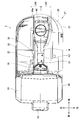
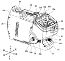
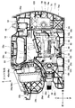
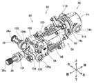
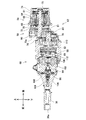
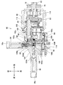
- FIG. 1 shows typically the state at the time of use of the high pressure washing machine 2 of an Example. It is the perspective view which looked at the high pressure washing machine 2 of an example from the front right upper part. It is the top view which looked at the high pressure washing machine 2 of an example from the upper part. It is the side view which looked at the high pressure washing machine 2 of an example from the left. It is the perspective view which looked at the state which removed the battery box cover 24 and the accessory box 26 of the high pressure washing machine 2 of an Example from the front right upper part. It is the top view which looked at the state where battery box cover 24 was removed from high pressure washing machine 2 of an example from the upper part.
- the high-pressure washer comprises a pump mechanism that pressurizes water supplied to an inlet port and pumps the water from an outlet port, an electric motor that drives the pump mechanism, the pump mechanism, and the electric motor.
- the electric motor may include a housing for housing the motor, and a plurality of batteries detachably attached to the housing to supply power to the electric motor.
- a low-voltage battery can be used for a high-output high-pressure washing machine.
- the high-pressure cleaner further includes a top handle provided on an upper portion of the housing and having a longitudinal direction in a front-rear direction when the high-pressure cleaner is viewed from above. May be.
- the position of the center of gravity of the high-pressure cleaner in the left-right direction is located within a range of 1.5 times the width of the top handle in the left-right direction from the center line of the top handle. Is also good.
- the high-pressure cleaner further includes a top handle provided on an upper portion of the housing and having a longitudinal direction in a front-rear direction when the high-pressure cleaner is viewed from above. May be.
- the position of the center of gravity of the high-pressure washer in the front-rear direction when the plurality of batteries are attached may be located within a range from a front end to a rear end of a lower surface of the top handle.
- the high-pressure washer includes a pump mechanism that pressurizes water supplied to the water inlet and discharges the water from the water outlet in response to rotation of the drive shaft, and an electric motor that drives the output shaft.
- a power transmission mechanism for transmitting power from the output shaft to the drive shaft; and a housing for housing the pump mechanism, the electric motor, and the power transmission mechanism.
- the output shaft may be arranged substantially parallel to the drive shaft.
- the output shaft may be disposed above the drive shaft.
- the high-pressure cleaner may further include a battery detachably mounted on the housing and supplying power to the electric motor. A position of a lower end of the battery when the battery is attached may be disposed above the drive shaft.
- the battery may be damaged.
- the battery since the lower end of the battery is disposed above the drive shaft of the pump mechanism, the battery is disposed slightly above the pump mechanism. Therefore, even if water leaks from the pump mechanism, it is possible to prevent the water from being applied to the battery, and to prevent the battery from breaking down.
- the high pressure washer may be housed in the housing and may further include an ECU for controlling operation of the electric motor.
- the ECU may be arranged above the pump mechanism.
- the high-pressure washer comprises a pump mechanism that pressurizes water supplied to an inlet port and pumps the water from an outlet port, an electric motor that drives the pump mechanism, the pump mechanism, and the electric motor.
- a housing for housing the motor may be provided.
- An outer surface of the housing closest to the electric motor may have a shape that cannot stand alone when the outer surface is a mounting surface.
- the non-self-supporting shape here refers to, for example, the shape of the mounting surface that does not come into contact with any plane at three points surrounding the point where the center of gravity of the high-pressure washing machine is projected.
- the high pressure washer can be made self-supporting with the outer surface closest to the electric motor as the mounting surface, the high pressure washer will be used in that state, and if water accumulates inside the housing, the electric motor will be sprayed with water and malfunction. There is a possibility that. According to the above configuration, when the outer surface closest to the electric motor is used as the mounting surface, the high-pressure washer cannot stand alone, so that it is possible to prevent the high-pressure washer from being used in that state. For this reason, when water accumulates inside the housing, it is possible to prevent water from being applied to the electric motor, and to prevent the electric motor from breaking down.
- the outer surface of the housing closest to the electric motor may have a shape that is rounded in two directions perpendicular to each other.
- the outer surface of the housing closest to the electric motor may have an outwardly projecting shape.
- the high-pressure cleaner may further include a battery that supplies power to the electric motor, and an openable / closable cover member that shields a space in which the battery is housed.
- the cover member In the high-pressure washing machine, when the high-pressure washing machine is mounted, the cover member may be in a closed state.
- the cover member is closed when the high pressure washer is used in a mounted state, so that water can be prevented from flowing into the space in which the battery is stored.
- washing water such as water is supplied to a high-pressure washing machine 2 from a water supply source 10 such as tap water through a pressure-resistant hose 12.
- the high-pressure washing machine 2 pressurizes the washing water and supplies high-pressure washing water to the trigger gun 16 via the high-pressure hose 14.
- a nozzle 18 is attached to the trigger gun 16.
- the trigger gun 16 switches between a state in which the cleaning water is supplied to the nozzle 18 and a state in which the supply of the cleaning water to the nozzle 18 is shut off in response to a user operation.
- the nozzle 18 injects washing water supplied from the trigger gun 16 from the tip.
- the high-pressure cleaner 2 includes a left housing 20, a right housing 22, a battery box cover 24, and an accessory box 26.
- the left housing 20, the right housing 22, the battery box cover 24, and the accessory box 26 are collectively referred to simply as a housing 27.
- the left housing 20 and the right housing 22 form a main housing 28, a battery box 30, and a top handle 32.
- the left housing 20 defines the outer shape of the left half surface of the main body housing 28, the battery box 30, and the top handle 32
- the right housing 22 defines the main housing 28, the battery box 30, and the right side of the top handle 32.
- the outer shape of the half surface is specified.
- the body housing 28 has a substantially rectangular parallelepiped shape in which the vertical direction is larger than the horizontal direction, and the front-back direction is larger than the vertical direction.
- a water inlet joint 34 projecting rightward is provided below the right front surface of the main body housing 28.
- the water inlet joint 34 projects from the inside of the main body housing 28 to the outside, and the pressure-resistant hose 12 (see FIG. 1) is detachable.
- the water inlet joint 34 has a water inlet 34a into which the cleaning water flows.
- a water outlet joint 36 projecting forward is provided below the front surface of the main body housing 28.
- the water discharge joint 36 protrudes from the inside of the main body housing 28 to the outside, and the high pressure hose 14 (see FIG. 1) is detachable.
- the water outlet joint 36 has a water outlet 36a from which the washing water flows.
- a battery box 30 is provided above and in front of the main body housing 28.
- the battery box 30 has a box-like shape opened upward and forward.
- the outer surface of the left side of the battery box 30 is substantially flush with the outer surface of the left side of the main body housing 28, and the outer surface of the right side protrudes rightward from the outer right side of the main body housing 28.
- inside the battery box 30 there are provided a battery attachment portion 40a to which the battery 38a can be attached and detached, and a battery attachment portion 40b to which the battery 38b can be attached and detached. As shown in FIG.
- each of the batteries 38a and 38b is a secondary battery such as a lithium ion battery.
- the rated voltage of the batteries 38a and 38b is, for example, 18V.
- the batteries 38a and 38b are detachable from the battery mounting portions 40a and 40b by sliding in a predetermined sliding direction with respect to the battery mounting portions 40a and 40b. As shown in FIG. 7, the sliding direction of the batteries 38a, 38b is inclined such that the upper part is inclined slightly forward with respect to the vertical direction of the main body housing 28.
- the position and orientation of the battery 38a attached to the battery attachment portion 40a are the same as the position and orientation of the battery 38b attached to the battery attachment portion 40b. , Almost match.
- the batteries 38a, 38b are attached to the battery attachment portions 40a, 40b, the batteries 38a, 38b are electrically connected in series, and the total voltage (for example, 36V) of the rated voltages (for example, 18V) of the batteries 38a, 38b is set. Electric power is supplied to the high-pressure washing machine 2.
- a battery box cover 24 is provided above the battery box 30.
- the battery box cover 24 is connected to the battery box 30 so as to be rotatable around a rotation shaft 30a (see FIGS. 5 and 6).
- the rotating shaft 30a is disposed above and behind the battery box 30, and has a longitudinal direction in the left-right direction.
- the battery box cover 24 is urged in the closing direction by a torsion spring (not shown).
- a latch 42 is provided at the tip of the battery box cover 24.
- a latch receiver 30 b is formed in the upper front of the battery box 30.
- the battery box cover 24 By operating the latch 42 and engaging the latch receiver 30b with the battery box cover 24 closed, the battery box cover 24 is maintained in the closed state. From this state, when the latch 42 is operated to release the engagement with the latch receiver 30b and the tip of the battery box cover 24 is pushed up against the urging force of the torsion spring, the battery box cover 24 is opened. State. As shown in FIG. 6, a resin sealing member 44 is provided on the periphery of the opening of the battery box 30. For this reason, when the battery box cover 24 is closed and the latch 42 is engaged with the latch receiver 30b, the gap between the battery box 30 and the battery box cover 24 is sealed by the seal member 44. It is possible to prevent water from flowing into the inside.
- a through hole 30c is provided behind the battery box 30 for passing wiring from inside the battery box 30 to inside the main body housing 28.
- the wiring extending from the battery mounting portions 40a and 40b is drawn into the main body housing 28 through the through hole 30c.
- a sponge 46 is provided on the body housing 28 side of the through hole 30c.
- the sponge 46 is formed with a notch 46a capable of holding a wiring. Since the sponge 46 is provided in the through hole 30c, water flows into the battery box 30 from the inside of the main body housing 28 through the through hole 30c, or from the inside of the battery box 30 through the through hole 30c. Water can be prevented from flowing into the inside of the main body housing 28.
- a drain hole 30d is provided at the bottom of the battery box 30.
- the water inside the battery box 30 can be discharged to the inside of the main body housing 28 through the drain hole 30d.
- a support base 28 a protruding upward is formed above the rear of the main body housing 28.
- the top handle 32 is provided so as to connect a front upper part of the support base 28 a and a rear upper part of the battery box 30.
- the top handle 32 has a substantially cylindrical shape. The user can lift and transport the high-pressure washing machine 2 by gripping the top handle 32.
- An adjustment dial 48 for adjusting the discharge flow rate of the washing water from the water discharge joint 36 is provided on the upper surface of the support base 28a.
- an operation display panel 50 On the upper surface near the front end of the top handle 32, an operation display panel 50 for displaying the state of the high-pressure washing machine 2 to a user and receiving an operation input from the user is provided.
- the accessory box 26 is attached to the right side of the main body housing 28.
- the right outer surface of the accessory box 26 is substantially flush with the right outer surface of the battery box 30.
- the accessory box 26 has a box shape with an open top.
- the accessory box 26 has a substantially truncated conical shape near the water inlet joint 34.
- the distal end of the water inlet joint 34 does not protrude rightward from the outer surface of the accessory box 26. Therefore, even when the high-pressure washing machine 2 to which the pressure-resistant hose 12 is not connected falls from a high place and the right side of the high-pressure washing machine 2 collides with the ground, the tip of the water inlet joint 34 collides with the ground and is damaged. Can be prevented.
- the main body housing 28 has a substantially trapezoidal column-shaped recess near the water discharge joint 36.
- the distal end of the water discharge joint 36 does not protrude forward from a plane contacting the outer surface of the battery box 30 and the outer surface of the main body housing 28. Therefore, even when the high pressure washer 2 to which the high pressure hose 14 is not connected falls from a high place and the front of the high pressure washer 2 collides with the ground, the tip of the water discharge joint 36 collides with the ground and is damaged. Can be prevented.
- an ECU (Electronic Control Unit) 52 As shown in FIG. 7, an ECU (Electronic Control Unit) 52, a dial detection switch 54, an electric motor 56, a power transmission mechanism 58, a pump mechanism 60, and the like are housed inside the main body housing 28.
- the ECU 52 is arranged at the upper center inside the main body housing 28.
- the ECU 52 is disposed above the pump mechanism 60 and below the top handle 32.
- the ECU 52 determines that the lower end is located above the lower ends of the batteries 38a, 38b, and the upper end is located below the upper ends of the batteries 38a, 38b. Is located.
- the ECU 52 controls operations of various electric components mounted on the high-pressure cleaner 2.
- the dial detection switch 54 is arranged inside the support 28 a of the main body housing 28.
- the dial detection switch 54 detects the rotation angle of the adjustment dial 48.
- the operation display panel 50 and the dial detection switch 54 are connected to the ECU 52 via wiring (not shown).
- the ECU 52 is connected to the battery mounting portions 40a and 40b via wiring (not shown) penetrating through the through hole 30c.
- the ECU 52 is connected to the electric motor 56 via a wiring (not shown).
- the ECU 52 controls the operation of the electric motor 56 by controlling the power supplied from the batteries 38a and 38b to the electric motor 56 based on signals input from the operation display panel 50 and the dial detection switch 54.
- the electric motor 56, the power transmission mechanism 58, and the pump mechanism 60 are unitized as a motor pump unit 62.
- the electric motor 56 is, for example, an outer rotor type brushless DC motor. As shown in FIG. 11, the electric motor 56 includes a stator 64 around which a coil 61 is wound, a rotor 68 having a magnet 66, an output shaft 70 fixed to the rotor 68, and a fan fixed to the output shaft 70. 72, a motor housing 74 that houses the stator 64, the rotor 68, and the fan 72. The rear end of the output shaft 70 is rotatably supported by the motor housing 74 via a bearing 75. The front end of the output shaft 70 projects forward from the motor housing 74. At the front end of the output shaft 70, a gear portion 70a is formed.
- the motor housing 74 includes an air supply port 74a formed on the rear surface, an exhaust port 74b formed on the peripheral surface near the fan 72, and a through hole formed on the right side near the rear end. A hole 74c is provided.
- the coil 61 is connected to the ECU 52 via a wiring (not shown) penetrating the through hole 74c.
- the ECU 52 includes a switching element (not shown), and controls the operation of the electric motor 56 by controlling the voltage applied to the coil 61 by switching the conduction and non-conduction of the switching element.
- the electric motor 56 rotates the output shaft 70
- the rotation of the fan 72 causes air to flow into the motor housing 74 via the air supply port 74a.
- the air that has flowed in from the air supply port 74a passes through a space between the stator 64 and the rotor 68, and then flows out of the motor housing 74 through an exhaust port 74b located on the outer peripheral side of the fan 72.
- the power transmission mechanism 58 includes a spur gear 76 fixed to the drive shaft 78, and a gear housing 80 that houses the spur gear 76 and the gear portion 70a of the output shaft 70.
- the gear housing 80 is fixed to a front portion of the motor housing 74.
- the front end of the output shaft 70 is rotatably supported by the gear housing 80 via a bearing 81.
- the spur gear 76 is arranged so as to mesh with the gear portion 70a of the output shaft 70.
- the rear end of the drive shaft 78 is rotatably supported by the gear housing 80 via a bearing 83.
- the drive shaft 78 is disposed substantially parallel to the output shaft 70.
- the drive shaft 78 is disposed at a position offset by a predetermined amount downward with respect to the output shaft 70.
- the rotation of the output shaft 70 is reduced in the power transmission mechanism 58 at a predetermined reduction ratio and transmitted to the drive shaft 78.
- the pump mechanism 60 includes a drive shaft 78, a wobble plate 82, a plurality of pistons 84, a plurality of suction valves 86 and a plurality of discharge valves 88 respectively corresponding to the plurality of pistons 84, and a spring.
- a retainer 90, a pressure pin 92, a detection switch 94, a relief valve 96, a pump housing 98, a piston cylinder 100, a piston housing 102, a pump head 104, a valve holder 106, and an adjust holder 108 are provided. I have.
- Wobble plate 82 is housed in pump housing 98.
- the wobble plate 82 is fixed to the front end of the drive shaft 78.
- the drive shaft 78 is rotatably supported by the pump housing 98 via a bearing 110.
- the front surface of the wobble plate 82 is inclined with respect to the rotation axis of the drive shaft 78.
- the rear ends of the plurality of pistons 84 are in contact with the front surface of the wobble plate 82, respectively.
- the plurality of pistons 84 are each supported by the piston cylinder 100 so as to be slidable in the front-rear direction.
- the piston cylinder 100 is fixed to a front part of the pump housing 98.
- Each of the plurality of pistons 84 is urged rearward by a corresponding spring 112.
- the plurality of pistons 84 slide back and forth with the rotation of the wobble plate 82.
- the piston housing 102 is fixed to the front of the piston cylinder 100.
- a suction chamber 102a, a discharge chamber 102b, and a plurality of piston chambers 102c respectively corresponding to the plurality of pistons 84 are formed in the piston housing 102.
- Each of the plurality of piston chambers 102c is provided with a corresponding plurality of suction valves 86 and a plurality of discharge valves 88, respectively.
- Each of the plurality of piston chambers 102c communicates with the suction chamber 102a via the corresponding suction valve 86, and communicates with the discharge chamber 102b via the corresponding discharge valve 88.
- the rear portion of each of the plurality of piston chambers 102c is closed by the front surface of the corresponding piston 84.
- Each of the plurality of suction valves 86 is a check valve, and when the piston 84 retreats, suction water is sucked from the suction chamber 102a into the piston chamber 102c, and when the piston 84 moves forward, the cleaning water is drawn from the piston chamber 102c into the suction chamber. The outflow of cleaning water to 102a is prohibited.
- Each of the plurality of discharge valves 88 is a check valve, and discharges washing water from the piston chamber 102c to the discharge chamber 102b when the piston 84 advances, and when the piston 84 retreats, the discharge chamber 102b moves from the discharge chamber 102b to the piston chamber. The flow of the cleaning water into 102c is prohibited.
- the pump head 104 is fixed to the front part of the piston housing 102.
- the pump head 104 has a water inlet chamber 104a to which the water inlet joint 34 is connected, a water outlet chamber 104b to which the water outlet joint 36 is connected, and a pressure detection chamber 104c.
- the water inlet chamber 104a communicates with the suction chamber 102a of the piston housing 102.
- the water discharge chamber 104b communicates with the discharge chamber 102b of the piston housing 102.
- the flush chamber 104b is provided with a valve holder 106 and an adjust holder 108.
- the valve holder 106 holds a plurality of discharge valves 88.
- a spring retainer 90 is provided between the valve holder 106 and the adjust holder 108.
- the spring retainer 90 allows the washing water to flow from the discharge chamber 102b to the water discharge chamber 104b when the pressure of the water discharge chamber 104b is lower than the pressure of the discharge chamber 102b, and the pressure of the water discharge chamber 104b is reduced to the pressure of the discharge chamber 102b. When it is higher than the above, the flow of the washing water from the discharge chamber 102b to the water discharge chamber 104b is prohibited.
- a relief valve 96 is provided in the water inlet chamber 104a. The relief valve 96 shuts off the relief path 104d when the pressure in the water inlet chamber 104a is higher than the pressure in the water outlet chamber 104b, and disconnects the relief path 104d when the pressure in the water inlet chamber 104a is lower than the pressure in the water outlet chamber 104b. Open. When the relief path 104d is opened, the pressure in the water discharge chamber 104b is reduced to the pressure in the water inlet chamber 104a.
- a pressure pin 92 is provided in the pressure detection chamber 104c.
- the pressure detection chamber 104c is partitioned by a pressure pin 92 into a space on the front side and a space on the rear side.
- the pressure pin 92 is supported by the pump head 104 so as to be slidable in the front-rear direction.
- the pressure pin 92 is urged forward by a spring 114.
- Behind the pressure pin 92 a detection switch 94 is arranged.
- the detection switch 94 is connected to the ECU 52 via a wiring (not shown).
- the space on the front side of the pressure pin 92 of the pressure detection chamber 104c communicates with the space on the downstream side of the adjust holder 108 of the water discharge chamber 104b via the first pressure detection path 104e.
- the space behind the pressure pin 92 in the pressure detection chamber 104c communicates with the space upstream of the adjustment holder 108 in the water discharge chamber 104b via the second pressure detection path 104f.
- the trigger mechanism 16 switches from a state in which the washing water is supplied to the nozzle 18 to a state in which the supply of the washing water to the nozzle 18 is shut off while the pump mechanism 60 is discharging the washing water
- the pressure in the water discharge chamber 104b rises rapidly.
- the spring retainer 90 prohibits the washing water from flowing from the discharge chamber 102b to the water discharge chamber 104b, and the pressure pin 92 moves rearward and comes into contact with the detection switch 94.
- the ECU 52 recognizes from the detection signal of the detection switch 94 that the trigger gun 16 has switched from a state in which the cleaning water is supplied to the nozzle 18 to a state in which the supply of the cleaning water to the nozzle 18 is shut off, and the electric motor 56 To stop.
- the relief valve 96 is opened to open the relief path 104d, and the pressure in the water discharge chamber 104b is reduced to the pressure in the water input chamber 104a.
- the motor housing 74 has a substantially cylindrical left support portion 74d protruding leftward from the left side surface, and a substantially cylindrical right support portion protruding rightward from the right side surface. 74e.
- the left support portion 74d is supported by the left housing 20 via a substantially cylindrical anti-vibration rubber 116 surrounding the outer peripheral side of the left support portion 74d.
- the right support portion 74e is supported by the right housing 22 via a substantially cylindrical anti-vibration rubber 118 surrounding the outer peripheral side of the right support portion 74e.
- the pump head 104 includes a substantially cylindrical left support portion 104g that protrudes leftward from the left side surface.
- a substantially cylindrical right-side support portion 104h is formed near the water inlet chamber 104a of the pump head 104.
- the left supporting portion 104g is supported by the left housing 20 via a substantially cylindrical anti-vibration rubber 120 surrounding the outer peripheral side of the left supporting portion 104g.
- the right support portion 104h is supported by the right housing 22 via a substantially cylindrical anti-vibration rubber 122 surrounding the outer peripheral side of the right support portion 104h.
- the water discharge joint 36 is supported by the left housing 20 and the right housing 22 via a substantially cylindrical anti-vibration rubber 124 surrounding the outer peripheral side of the water joint 36.
- the inside of the main body housing 28 includes a pump chamber 28c and an air supply chamber 28d disposed above and in front of the pump chamber 28c by a partition wall 28b formed on the left housing 20 and the right housing 22. It is divided into an ECU room 28e arranged above the pump room 28c, a motor room 28f arranged behind the pump room 28c and the ECU room 28e, and a switch room 28g inside the support base 28a.
- the air supply chamber 28d communicates with the outside of the main body housing 28 through an air supply hole 28h (see FIG. 5) formed at a lower front part of the right surface of the right housing 22.
- the air supply chamber 28d extends rearward and upward along the lower surface of the battery box 30, and communicates with the lower front part of the ECU chamber 28e.
- the lower rear part of the ECU room 28e communicates with the upper front part of the motor room 28f.
- a through hole 28i through which the electric motor 56 passes is formed in the partition wall 28b between the pump chamber 28c and the motor chamber 28f.
- the stator 64 and the rotor 68 of the electric motor 56 are disposed in the motor chamber 28f, and the fan 72, the power transmission mechanism 58, and the pump mechanism 60 of the electric motor 56 It is arranged in the chamber 28c.
- the air supply port 74a of the motor housing 74 is disposed in the motor chamber 28f
- the exhaust port 74b of the motor housing 74 is disposed in the pump chamber 28c.
- a discharge hole 28j for discharging water or air from the pump chamber 28c to the outside of the main body housing 28 is formed.
- the rotation of the fan 72 causes air to flow into the air supply chamber 28d from the outside of the main body housing 28 through the air supply holes 28h.
- the air that has flowed into the air supply chamber 28d passes through the ECU chamber 28e and flows into the motor chamber 28f.
- the air flowing into the motor chamber 28f flows into the motor housing 74 via the air supply port 74a, flows from the rear to the front inside the motor housing 74, and flows into the pump chamber 28c via the exhaust port 74b. I do.
- the air that has flowed into the pump chamber 28c is discharged to the outside of the main body housing 28 through the discharge hole 28j.
- the drain hole 30d of the battery box 30 communicates with the air supply chamber 28d. For this reason, the water that has flowed into the main body housing 28 from the battery box 30 through the drain hole 30d does not flow into the ECU room 28e, the motor room 28f, the switch room 28g, and the like.
- the position of the center of gravity G1 with the batteries 38a and 38b attached is the top position in the left-right direction. It is located within 1.5 times the width W of the top handle 32 in the left-right direction from the center line of the handle 32. Therefore, when the high pressure washer 2 with the batteries 38a and 38b attached thereto is gripped by the top handle 32 and lifted, it is easy to balance in the left-right direction.
- the position of the center of gravity G2 with the batteries 38a and 38b removed is the center line of the top handle 32 in the left-right direction. Is located within a range of 1.5 times the width W of the top handle 32 in the left-right direction. Therefore, when the high-pressure washing machine 2 with the batteries 38a and 38b removed is gripped by the top handle 32 and lifted, it is easy to balance in the left-right direction.
- the position of the center of gravity G1 with the batteries 38a and 38b attached is The lower surface of the top handle 32 is located within a range from the front end to the rear end. Therefore, when the high pressure washer 2 with the batteries 38a and 38b attached thereto is gripped by the top handle 32 and lifted, it is easy to balance in the front-rear direction.
- the position of the center of gravity G2 with the batteries 38a and 38b removed is lower than the lower surface of the top handle 32 in the front-rear direction. Is located within the range from the front end to the rear end. For this reason, when the high-pressure cleaner 2 with the batteries 38a and 38b removed is gripped and lifted by the top handle 32, it is easy to balance in the front-rear direction.
- a water inlet 34 a is arranged on the right side of the housing 27, and a water outlet 36 a is arranged on the front side of the housing 27.
- the outer surface of the housing 27 where the water inlet 34a and the water outlet 36a are not arranged that is, the rear surface which is the outer surface closest to the electric motor 56 among the bottom surface, the left surface, the rear surface, and the upper surface is It has a rounded shape in the vertical and horizontal directions. For this reason, when the rear surface of the housing 27 is used as the mounting surface, the high-pressure cleaner 2 cannot stand alone and falls down.
- the shape of the rear surface of the housing 27 may be any shape as long as it is not a self-supporting shape when used as the mounting surface.
- the high-pressure washing machine 2 includes the pump mechanism 60 that pressurizes the water supplied to the water inlet 34a and sends out the water from the water outlet 36a, and an electric motor that drives the pump mechanism 60.
- the housing includes a motor 56, a pump mechanism 60 and an electric motor 56, and a plurality of batteries 38 a and 38 b detachably attached to the housing 27 and supplying power to the electric motor 56.
- the electric motor 56 can be supplied with a high voltage (for example, 36 V) by electrically connecting a plurality of low-voltage (for example, 18 V) batteries 38 a and 38 b in series.
- the low-voltage batteries 38a and 38b can be used for the high-output high-pressure washing machine 2.
- the high-pressure cleaner 2 is provided on an upper portion of the housing 27 and further includes a top handle 32 having a longitudinal direction in the front-rear direction when the high-pressure cleaner 2 is viewed from above. Have.
- the position of the center of gravity G1 of the high-pressure washer 2 in the left-right direction when the plurality of batteries 38a, 38b are attached is within 1.5 times the width of the top handle 32 in the left-right direction from the center line of the top handle 32. positioned.
- the high-pressure cleaner 2 is provided on an upper portion of the housing 27 and further includes a top handle 32 having a longitudinal direction in the front-rear direction when the high-pressure cleaner 2 is viewed from above. Have.
- the position of the center of gravity G1 of the high-pressure cleaner 2 in the front-rear direction is located within the range from the front end to the rear end of the lower surface of the top handle 32.
- the high-pressure washer 2 includes a pump mechanism 60 that pressurizes water supplied to the water inlet 34a and feeds the water through the water outlet 36a in response to rotation of the drive shaft 78, and an output shaft 70.
- the output shaft 70 is disposed substantially parallel to the drive shaft 78.
- the output shaft 70 is disposed above the drive shaft 78.
- the electric motor 56 is disposed slightly above the pump mechanism 60. Therefore, even when water leaks from the pump mechanism 60, it is possible to prevent water from being applied to the electric motor 56, and to prevent the electric motor 56 from breaking down.
- the high-pressure cleaner 2 further includes batteries 38 a and 38 b detachably mounted on the housing 27 and supplying power to the electric motor 56. When the batteries 38a, 38b are attached, the lower ends of the batteries 38a, 38b are located above the drive shaft 78.
- the batteries 38a, 38b may be damaged.
- the batteries 38a, 38b since the lower ends of the batteries 38a, 38b are disposed above the drive shaft 78 of the pump mechanism 60, the batteries 38a, 38b are disposed slightly above the pump mechanism 60. Therefore, even if water leaks from the pump mechanism 60, it is possible to prevent water from being applied to the batteries 38a and 38b, and to prevent the batteries 38a and 38b from breaking down.
- the high-pressure cleaner 2 is housed in the housing 27 and may further include the ECU 52 that controls the operation of the electric motor 56.
- the ECU 52 is arranged above the pump mechanism 60.
- the ECU 52 may break down.
- the ECU 52 is disposed above the pump mechanism 60. For this reason, even if water leaks from the pump mechanism 60, it is possible to prevent water from splashing on the ECU 52 and prevent the ECU 52 from breaking down.
- the high-pressure cleaner 2 includes a pump mechanism 60 that pressurizes water supplied to the water inlet 34a and feeds the water through the water outlet 36a, an electric motor 56 that drives the pump mechanism 60, and a pump.
- the housing 27 that houses the mechanism 60 and the electric motor 56 is provided.
- the outer surface of the housing 27 which is closest to the electric motor 56 has a shape that cannot stand alone when the outer surface is used as a mounting surface.
- the high pressure washer 2 can be made independent by using the outer surface closest to the electric motor 56 as a mounting surface, the high pressure washer 2 is used in that state, and when water accumulates inside the housing 27, the electric motor 56 It may be damaged by water. According to the above configuration, the high pressure washer 2 cannot stand on its own when the outer surface closest to the electric motor 56 is used as the mounting surface, so that it is possible to prevent the high pressure washer 2 from being used in that state. Therefore, when water accumulates inside the housing 27, it is possible to prevent the electric motor 56 from being splashed with water, and to prevent the electric motor 56 from breaking down.
- the outer surface of the housing 27 closest to the electric motor 56 has a shape that is rounded in two directions orthogonal to each other.
- the outer surface of the housing 27 closest to the electric motor 56 has an outwardly projecting shape.
- the high-pressure cleaner 2 includes a battery 38a, 38b that supplies power to the electric motor 56, and an openable / closable battery box cover 24 that shields a space in which the batteries 38a, 38b are housed. (Example of a cover member).
- the battery box cover 24 In the high-pressure washing machine 2, when the high-pressure washing machine 2 is mounted, the battery box cover 24 is in a closed state.
- the battery box cover 24 is closed when the high pressure washer 2 is used in a mounted state, so that water is prevented from flowing into the space in which the batteries 38a and 38b are stored. can do.
Landscapes
- Engineering & Computer Science (AREA)
- Mechanical Engineering (AREA)
- General Engineering & Computer Science (AREA)
- Cleaning By Liquid Or Steam (AREA)
- Chemical & Material Sciences (AREA)
- Chemical Kinetics & Catalysis (AREA)
- Electrochemistry (AREA)
- General Chemical & Material Sciences (AREA)
- Details Of Reciprocating Pumps (AREA)
- Life Sciences & Earth Sciences (AREA)
- Biophysics (AREA)
- Computer Hardware Design (AREA)
Abstract
本明細書が開示する高圧洗浄機は、入水口に供給される水を加圧して出水口から送り出すポンプ機構と、前記ポンプ機構を駆動する電動モータと、前記ポンプ機構および前記電動モータを収容するハウジングを備えていてもよい。前記ハウジングの、前記電動モータに最も近接する外面が、その外面を載置面とした時に自立不能な形状を有していてもよい。
Description
本明細書で開示する技術は、高圧洗浄機に関する。
特開2016-2537号公報には、入水口に供給される水を加圧して出水口から送り出すポンプ機構と、前記ポンプ機構を駆動する電動モータと、前記ポンプ機構および前記電動モータを収容するハウジングを備える高圧洗浄機が開示されている。
ハウジングの外部から水が侵入したり、ポンプ機構から水が漏出することによって、ハウジングの内部に水が溜まることがある。高圧洗浄機を載置した状態で、電動モータがハウジングの載置面近傍に位置していると、ハウジングの内部に水が溜まったときに、電動モータに水がかかって故障してしまうおそれがある。本明細書では、ハウジングの内部に水が溜まった場合であっても、電動モータが故障することを防止することが可能な技術を提供する。
本明細書が開示する高圧洗浄機は、入水口に供給される水を加圧して出水口から送り出すポンプ機構と、前記ポンプ機構を駆動する電動モータと、前記ポンプ機構および前記電動モータを収容するハウジングを備えていてもよい。前記ハウジングの、前記電動モータに最も近接する外面が、その外面を載置面とした時に自立不能な形状を有していてもよい。なお、ここでいう自立不能な形状とは、例えば、あらゆる平面に対して、高圧洗浄機の重心を投影した点を取り囲む3点で接することがない載置面の形状をいう。
電動モータに最も近接する外面を載置面として高圧洗浄機を自立可能とすると、その状態で高圧洗浄機が使用されて、ハウジングの内部に水が溜まった時に、電動モータに水がかかって故障するおそれがある。上記の構成によれば、電動モータに最も近接する外面を載置面とした時に高圧洗浄機が自立できないので、その状態で高圧洗浄機が使用されることを防止することができる。このため、ハウジングの内部に水が溜まった場合に、電動モータに水がかかってしまうことを防止することができ、電動モータが故障することを防止することができる。
以下では、本発明の代表的かつ非限定的な具体例について、図面を参照して詳細に説明する。この詳細な説明は、本発明の好ましい例を実施するための詳細を当業者に示すことを単純に意図しており、本発明の範囲を限定することを意図したものではない。また、以下に開示される追加的な特徴ならびに発明は、さらに改善された高圧洗浄機、その製造方法及び使用方法を提供するために、他の特徴や発明とは別に、又は共に用いることができる。
また、以下の詳細な説明で開示される特徴や工程の組み合わせは、最も広い意味において本発明を実施する際に必須のものではなく、特に本発明の代表的な具体例を説明するためにのみ記載されるものである。さらに、上記及び下記の代表的な具体例の様々な特徴、ならびに、独立及び従属クレームに記載されるものの様々な特徴は、本発明の追加的かつ有用な実施形態を提供するにあたって、ここに記載される具体例のとおりに、あるいは列挙された順番のとおりに組合せなければならないものではない。
本明細書及び/又は請求の範囲に記載された全ての特徴は、実施例及び/又はクレームに記載された特徴の構成とは別に、出願当初の開示ならびにクレームされた特定事項に対する限定として、個別に、かつ互いに独立して開示されることを意図するものである。さらに、全ての数値範囲及びグループ又は集団に関する記載は、出願当初の開示ならびにクレームされた特定事項に対する限定として、それらの中間の構成を開示する意図を持ってなされている。
1つまたはそれ以上の実施形態において、高圧洗浄機は、入水口に供給される水を加圧して出水口から送り出すポンプ機構と、前記ポンプ機構を駆動する電動モータと、前記ポンプ機構および前記電動モータを収容するハウジングと、前記ハウジングに着脱可能に取り付けられ、前記電動モータに給電する複数のバッテリを備えていてもよい。
上記の構成によれば、例えば複数の低電圧のバッテリを電気的に直列に接続することで、電動モータに高電圧で給電することができる。高出力の高圧洗浄機に、低電圧のバッテリを使用可能とすることができる。
1つまたはそれ以上の実施形態において、前記高圧洗浄機は、前記ハウジングの上部に設けられており、前記高圧洗浄機を上方から平面視したときに前後方向に長手方向を有するトップハンドルをさらに備えていてもよい。前記複数のバッテリを取り付けたときの、前記高圧洗浄機の重心の左右方向の位置が、前記トップハンドルの中心線から左右方向に前記トップハンドルの幅の1.5倍の範囲内に位置してもよい。
上記の構成によれば、トップハンドルを把持して高圧洗浄機を持ち上げた時に、左右方向のバランスを取りやすくなる。
1つまたはそれ以上の実施形態において、前記高圧洗浄機は、前記ハウジングの上部に設けられており、前記高圧洗浄機を上方から平面視したときに前後方向に長手方向を有するトップハンドルをさらに備えていてもよい。前記複数のバッテリを取り付けたときの、前記高圧洗浄機の重心の前後方向の位置が、前記トップハンドルの下面の前端から後端の範囲内に位置してもよい。
上記の構成によれば、トップハンドルを把持して高圧洗浄機を持ち上げた時に、前後方向のバランスを取りやすくなる。
1つまたはそれ以上の実施形態において、高圧洗浄機は、駆動シャフトの回転に応じて、入水口に供給される水を加圧して出水口から送り出すポンプ機構と、出力シャフトを駆動する電動モータと、前記出力シャフトから前記駆動シャフトへ動力を伝達する動力伝達機構と、前記ポンプ機構、前記電動モータおよび前記動力伝達機構を収容するハウジングを備えていてもよい。前記出力シャフトが、前記駆動シャフトに対して、略平行に配置されていてもよい。前記出力シャフトが、前記駆動シャフトよりも、上方に配置されていてもよい。
上記の構成では、電動モータの出力シャフトがポンプ機構の駆動シャフトよりも上方に配置されているので、電動モータはポンプ機構に比べてやや上方に配置される。このため、ポンプ機構から水が漏出した場合であっても、電動モータに水がかかることを防止することができ、電動モータが故障することを防止することができる。
1つまたはそれ以上の実施形態において、前記高圧洗浄機は、前記ハウジングに着脱可能に取り付けられ、前記電動モータに給電するバッテリをさらに備えていてもよい。前記バッテリを取り付けたときの、前記バッテリの下端の位置が、前記駆動シャフトよりも、上方に配置されていてもよい。
バッテリに水がかかってしまうと、バッテリが故障してしまうおそれがある。上記の構成では、バッテリの下端がポンプ機構の駆動シャフトよりも上方に配置されているので、バッテリはポンプ機構に比べてやや上方に配置される。このため、ポンプ機構から水が漏出した場合であっても、バッテリに水がかかることを防止することができ、バッテリが故障することを防止することができる。
1つまたはそれ以上の実施形態において、前記高圧洗浄機は、前記ハウジングに収容されており、前記電動モータの動作を制御するECUをさらに備えていてもよい。前記ECUが、前記ポンプ機構の上方に配置されていてもよい。
ECUに水がかかってしまうと、ECUが故障してしまうおそれがある。上記の構成では、ECUがポンプ機構の上方に配置されている。このため、ポンプ機構から水が漏出した場合であっても、ECUに水がかかることを防止することができ、ECUが故障することを防止することができる。
1つまたはそれ以上の実施形態において、高圧洗浄機は、入水口に供給される水を加圧して出水口から送り出すポンプ機構と、前記ポンプ機構を駆動する電動モータと、前記ポンプ機構および前記電動モータを収容するハウジングを備えていてもよい。前記ハウジングの、前記電動モータに最も近接する外面が、その外面を載置面とした時に自立不能な形状を有していてもよい。なお、ここでいう自立不能な形状とは、例えば、あらゆる平面に対して、高圧洗浄機の重心を投影した点を取り囲む3点で接することがない載置面の形状をいう。
電動モータに最も近接する外面を載置面として高圧洗浄機を自立可能とすると、その状態で高圧洗浄機が使用されて、ハウジングの内部に水が溜まった時に、電動モータに水がかかって故障するおそれがある。上記の構成によれば、電動モータに最も近接する外面を載置面とした時に高圧洗浄機が自立できないので、その状態で高圧洗浄機が使用されることを防止することができる。このため、ハウジングの内部に水が溜まった場合に、電動モータに水がかかってしまうことを防止することができ、電動モータが故障することを防止することができる。
1つまたはそれ以上の実施形態において、前記ハウジングの、前記電動モータに最も近接する外面が、互いに直交する二方向に丸みを帯びた形状を有していてもよい。
上記の構成によれば、電動モータに最も近接する外面を載置面とした時に、確実に自立不能とすることができる。
1つまたはそれ以上の実施形態において、前記ハウジングの、前記電動モータに最も近接する外面が、外向きに突出する形状を有していてもよい。
上記の構成によれば、電動モータに最も近接する外面を載置面とした時に、確実に自立不能とすることができる。
1つまたはそれ以上の実施形態において、前記高圧洗浄機は、前記電動モータに電力を供給するバッテリと、前記バッテリが収容される空間を遮蔽する開閉可能なカバー部材をさらに備えていてもよい。前記高圧洗浄機では、前記高圧洗浄機を載置した時に、前記カバー部材が閉じた状態となってもよい。
上記の構成によれば、高圧洗浄機を載置した状態で使用した時に、カバー部材が閉じた状態となるので、バッテリが収容される空間に水が流入することを防止することができる。
(実施例)
実施例の高圧洗浄機2について図面を参照しながら説明する。図1に示すように、高圧洗浄機2には、水道などの給水源10から耐圧ホース12を介して水などの洗浄水が供給される。高圧洗浄機2は、洗浄水を加圧して、高圧ホース14を介してトリガガン16に高圧の洗浄水を供給する。トリガガン16には、ノズル18が取り付けられている。トリガガン16は、ユーザの操作に応じて、ノズル18へ洗浄水を供給する状態と、ノズル18への洗浄水の供給を遮断する状態の間で切り換わる。ノズル18は、トリガガン16から供給される洗浄水を先端から噴射する。
実施例の高圧洗浄機2について図面を参照しながら説明する。図1に示すように、高圧洗浄機2には、水道などの給水源10から耐圧ホース12を介して水などの洗浄水が供給される。高圧洗浄機2は、洗浄水を加圧して、高圧ホース14を介してトリガガン16に高圧の洗浄水を供給する。トリガガン16には、ノズル18が取り付けられている。トリガガン16は、ユーザの操作に応じて、ノズル18へ洗浄水を供給する状態と、ノズル18への洗浄水の供給を遮断する状態の間で切り換わる。ノズル18は、トリガガン16から供給される洗浄水を先端から噴射する。
図2-図4に示すように、高圧洗浄機2は、左側ハウジング20と、右側ハウジング22と、バッテリボックスカバー24と、アクセサリボックス26を備えている。なお、以下では左側ハウジング20と、右側ハウジング22と、バッテリボックスカバー24と、アクセサリボックス26を総称して、単にハウジング27ともいう。図5に示すように、左側ハウジング20と右側ハウジング22によって、本体ハウジング28と、バッテリボックス30と、トップハンドル32が形成されている。左側ハウジング20は、本体ハウジング28と、バッテリボックス30と、トップハンドル32の左半面の外形形状を規定しており、右側ハウジング22は、本体ハウジング28と、バッテリボックス30と、トップハンドル32の右半面の外形形状を規定している。
本体ハウジング28は、上下方向が左右方向よりも大きく、前後方向が上下方向よりも大きい略直方体形状を有している。本体ハウジング28の右面の前方下方には、右方向に突出する入水継手34が設けられている。入水継手34は、本体ハウジング28の内部から外部に突出しており、耐圧ホース12(図1参照)を着脱可能である。入水継手34は、洗浄水が流入する入水口34aを備えている。本体ハウジング28の前面の下方には、前方向に突出する出水継手36が設けられている。出水継手36は、本体ハウジング28の内部から外部に突出しており、高圧ホース14(図1参照)を着脱可能である。出水継手36は、洗浄水が流出する出水口36aを備えている。
本体ハウジング28の前方上方に、バッテリボックス30が設けられている。バッテリボックス30は、前方上方に向けて開口した箱型形状を有している。バッテリボックス30は、左側の外面は本体ハウジング28の左側の外面と略面一となっており、右側の外面は本体ハウジング28の右側の外面よりも右側に突出している。図6、図7に示すように、バッテリボックス30の内部には、バッテリ38aを着脱可能なバッテリ取付部40aと、バッテリ38bを着脱可能なバッテリ取付部40bが設けられている。図6に示すように、バッテリ38a、38bをバッテリ取付部40a、40bに取り付けた状態では、バッテリ38a、38bは左右方向に並んで配置されている。バッテリ38a、38bは、いずれも、リチウムイオンバッテリ等の二次電池である。バッテリ38a、38bの定格電圧は、例えば18Vである。バッテリ38a、38bは、バッテリ取付部40a、40bに対して所定のスライド方向にスライドさせることで、バッテリ取付部40a、40bに着脱可能である。図7に示すように、バッテリ38a、38bのスライド方向は、本体ハウジング28の上下方向に対して、上方がやや前方に傾くように傾斜している。本体ハウジング28を左方(または右方)から平面視した時に、バッテリ取付部40aに取り付けた状態のバッテリ38aの位置および姿勢は、バッテリ取付部40bに取り付けた状態のバッテリ38bの位置および姿勢と、略一致している。バッテリ38a、38bをバッテリ取付部40a、40bに取り付けた状態では、バッテリ38a、38bは電気的に直列に接続されて、バッテリ38a、38bの定格電圧(例えば18V)の合計電圧(例えば36V)の電力が高圧洗浄機2に供給される。
図2-図4に示すように、バッテリボックス30の上部には、バッテリボックスカバー24が設けられている。バッテリボックスカバー24は、回動軸30a(図5、図6参照)周りに回動可能に、バッテリボックス30に連結されている。回動軸30aは、バッテリボックス30の後方上方に配置されており、左右方向に長手方向を有する。バッテリボックスカバー24は、図示しない捩じりバネによって、閉じる方向に付勢されている。バッテリボックスカバー24の先端には、ラッチ42が設けられている。図5、図6に示すように、バッテリボックス30の前方上方には、ラッチ受け30bが形成されている。バッテリボックスカバー24を閉じた状態で、ラッチ42を操作してラッチ受け30bに係合させることで、バッテリボックスカバー24は閉じた状態で維持される。この状態から、ラッチ42を操作してラッチ受け30bとの係合を解除して、捩じりバネの付勢力に抗してバッテリボックスカバー24の先端を押し上げると、バッテリボックスカバー24は開いた状態となる。図6に示すように、バッテリボックス30の開口の周縁には、樹脂製のシール部材44が設けられている。このため、バッテリボックスカバー24を閉じて、ラッチ42をラッチ受け30bに係合させた状態では、バッテリボックス30とバッテリボックスカバー24の間の隙間がシール部材44によってシールされるため、バッテリボックス30の内部に水が流入することを防止することができる。
図7に示すように、バッテリボックス30の後方には、バッテリボックス30の内部から本体ハウジング28の内部へ配線を通すための貫通孔30cが設けられている。バッテリ取付部40a、40bから伸びる配線は、貫通孔30cを介して、本体ハウジング28の内部に引き込まれる。貫通孔30cの本体ハウジング28側には、スポンジ46が設けられている。図8に示すように、スポンジ46には、配線を挟持可能な切り込み46aが形成されている。貫通孔30cにスポンジ46が設けられていることで、貫通孔30cを介して本体ハウジング28の内部からバッテリボックス30の内部に水が流入したり、貫通孔30cを介してバッテリボックス30の内部から本体ハウジング28の内部に水が流入することを防止することができる。
図7に示すように、バッテリボックス30の最下部には、水抜き孔30dが設けられている。これによって、仮にバッテリボックス30の内部に水が流入した場合でも、バッテリボックス30の内部の水を、水抜き孔30dを介して本体ハウジング28の内部へ排出することができる。
図2-図4に示すように、本体ハウジング28の後方上方には、上方に向けて突出する支持台28aが形成されている。トップハンドル32は、支持台28aの前方上方と、バッテリボックス30の後方上方を連結するように設けられている。トップハンドル32は略円筒形状を有している。ユーザはトップハンドル32を把持することで、高圧洗浄機2を持ち上げて運搬することができる。支持台28aの上面には、出水継手36からの洗浄水の吐出流量を調整するための調整ダイヤル48が設けられている。トップハンドル32の前端近傍の上面には、ユーザに高圧洗浄機2の状態を表示するとともに、ユーザからの操作入力を受け入れるための操作表示板50が設けられている。
アクセサリボックス26は、本体ハウジング28の右面に取り付けられている。アクセサリボックス26の右側の外面は、バッテリボックス30の右側の外面と略面一となっている。アクセサリボックス26は、上方が開口した箱型形状を形成している。高圧洗浄機2を使用していない時には、トリガガン16、ノズル18、耐圧ホース12、高圧ホース14等の付属品を、アクセサリボックス26に入れておくことができる。この状態で、ユーザがトップハンドル32を把持して高圧洗浄機2を持ち上げることで、高圧洗浄機2を付属品とともに運搬することができる。
アクセサリボックス26は、入水継手34の近傍において、略円錐台状に窪んだ形状を有している。入水継手34の先端は、アクセサリボックス26の外面よりも右側に突出していない。従って、耐圧ホース12を接続していない高圧洗浄機2が高所から落下して、高圧洗浄機2の右面が地面に衝突した場合でも、入水継手34の先端が地面に衝突して損傷することを防止することができる。
本体ハウジング28は、出水継手36の近傍において、略台形柱状に窪んだ形状を有している。出水継手36の先端は、バッテリボックス30の外面と本体ハウジング28の外面に接する平面よりも前側に突出していない。従って、高圧ホース14を接続していない高圧洗浄機2が高所から落下して、高圧洗浄機2の前面が地面に衝突した場合でも、出水継手36の先端が地面に衝突して損傷することを防止することができる。
図7に示すように、本体ハウジング28の内部には、ECU(Electronic Control Unit)52、ダイヤル検出スイッチ54、電動モータ56、動力伝達機構58、ポンプ機構60等が収容されている。ECU52は、本体ハウジング28の内部の上方中央に配置されている。ECU52は、ポンプ機構60の上方であって、トップハンドル32の下方に配置されている。バッテリ38a、38bをバッテリ取付部40a、40bに取り付けた状態では、ECU52は、下端がバッテリ38a、38bの下端よりも上方に位置し、上端がバッテリ38a、38bの上端よりも下方に位置するように、配置されている。ECU52は、高圧洗浄機2に搭載されている各種の電気部品の動作を制御する。ダイヤル検出スイッチ54は、本体ハウジング28の支持台28aの内部に配置されている。ダイヤル検出スイッチ54は、調整ダイヤル48の回転角度を検出する。操作表示板50とダイヤル検出スイッチ54は、それぞれ、図示しない配線を介して、ECU52に接続されている。また、ECU52は、貫通孔30cを貫通する配線(図示せず)を介して、バッテリ取付部40a、40bと接続されている。さらに、ECU52は、図示しない配線を介して、電動モータ56に接続されている。ECU52は、操作表示板50やダイヤル検出スイッチ54から入力される信号に基づいて、バッテリ38a、38bから電動モータ56に供給される電力を制御することで、電動モータ56の動作を制御する。
図9、図10に示すように、電動モータ56、動力伝達機構58およびポンプ機構60は、モータポンプユニット62としてユニット化されている。
電動モータ56は、例えばアウタロータ型のブラシレスDCモータである。図11に示すように、電動モータ56は、コイル61が巻回されたステータ64と、マグネット66を備えるロータ68と、ロータ68に固定された出力シャフト70と、出力シャフト70に固定されたファン72と、ステータ64、ロータ68およびファン72を収容するモータハウジング74を備えている。出力シャフト70の後端は、ベアリング75を介して、モータハウジング74に回転可能に支持されている。出力シャフト70の前端は、モータハウジング74から前方に突出している。出力シャフト70の前端には、ギヤ部70aが形成されている。
図10に示すように、モータハウジング74は、後面に形成された給気口74aと、ファン72の近傍の周面に形成された排気口74bと、後端近傍の右側面に形成された貫通孔74cを備えている。コイル61は、貫通孔74cを貫通する配線(図示せず)を介して、ECU52に接続されている。ECU52は、スイッチング素子(図示せず)を備えており、スイッチング素子の導通および非導通を切り替えてコイル61に印加される電圧を制御することで、電動モータ56の動作を制御する。電動モータ56が出力シャフト70を回転させると、ファン72の回転によって、給気口74aを介してモータハウジング74の内部に空気が流入する。給気口74aから流入した空気は、ステータ64とロータ68の間の空間を通過した後、ファン72の外周側に位置する排気口74bを介してモータハウジング74の外部に流出する。
図11に示すように、動力伝達機構58は、駆動シャフト78に固定されたスパーギヤ76と、スパーギヤ76および出力シャフト70のギヤ部70aを収容するギヤハウジング80を備えている。ギヤハウジング80は、モータハウジング74の前部に固定されている。出力シャフト70の前端は、ベアリング81を介してギヤハウジング80に回転可能に支持されている。スパーギヤ76は、出力シャフト70のギヤ部70aと噛み合うように配置されている。駆動シャフト78の後端は、ベアリング83を介してギヤハウジング80に回転可能に支持されている。駆動シャフト78は、出力シャフト70に対して略平行に配置されている。駆動シャフト78は、出力シャフト70に対して、下方に所定量オフセットした位置に配置されている。出力シャフト70の回転は、動力伝達機構58において所定の減速比で減速されて、駆動シャフト78に伝達する。
図12に示すように、ポンプ機構60は、駆動シャフト78と、ワッブルプレート82と、複数のピストン84と、複数のピストン84それぞれに対応する複数の吸入バルブ86および複数の吐出バルブ88と、スプリングリテーナ90と、プレッシャピン92と、検出スイッチ94と、リリーフバルブ96と、ポンプハウジング98と、ピストンシリンダ100と、ピストンハウジング102と、ポンプヘッド104と、バルブホルダ106と、アジャストホルダ108を備えている。
ワッブルプレート82は、ポンプハウジング98に収容されている。ワッブルプレート82は、駆動シャフト78の前端に固定されている。駆動シャフト78は、ベアリング110を介してポンプハウジング98に回転可能に支持されている。ワッブルプレート82の前面は、駆動シャフト78の回転軸に対して傾斜している。複数のピストン84は、それぞれ、後端がワッブルプレート82の前面に当接している。複数のピストン84は、それぞれ、前後方向に摺動可能に、ピストンシリンダ100に支持されている。ピストンシリンダ100は、ポンプハウジング98の前部に固定されている。複数のピストン84は、それぞれ、対応するバネ112によって、後方に向けて付勢されている。複数のピストン84は、ワッブルプレート82の回転に伴って、前後方向に摺動する。
ピストンハウジング102は、ピストンシリンダ100の前部に固定されている。ピストンハウジング102には、吸入室102aと、吐出室102bと、複数のピストン84それぞれに対応する複数のピストン室102cが形成されている。複数のピストン室102cのそれぞれには、対応する複数の吸入バルブ86と、複数の吐出バルブ88がそれぞれ設けられている。複数のピストン室102cのそれぞれは、対応する吸入バルブ86を介して吸入室102aに連通しているとともに、対応する吐出バルブ88を介して吐出室102bに連通している。複数のピストン室102cのそれぞれの後部は、対応するピストン84の前面によって閉塞されている。複数の吸入バルブ86のそれぞれは逆止弁であって、ピストン84が後退する時に、吸入室102aからピストン室102cに洗浄水を吸入するとともに、ピストン84が前進する時に、ピストン室102cから吸入室102aに洗浄水が流出することを禁止する。複数の吐出バルブ88のそれぞれは逆止弁であって、ピストン84が前進する時に、ピストン室102cから吐出室102bに洗浄水を吐出するとともに、ピストン84が後退する時に、吐出室102bからピストン室102cに洗浄水が流入することを禁止する。
ポンプヘッド104は、ピストンハウジング102の前部に固定されている。ポンプヘッド104には、入水継手34が接続される入水室104aと、出水継手36が接続される出水室104bと、圧力検出室104cが形成されている。入水室104aは、ピストンハウジング102の吸入室102aと連通している。出水室104bは、ピストンハウジング102の吐出室102bと連通している。出水室104bには、バルブホルダ106と、アジャストホルダ108が設けられている。バルブホルダ106は、複数の吐出バルブ88を保持している。バルブホルダ106とアジャストホルダ108の間には、スプリングリテーナ90が設けられている。スプリングリテーナ90は、出水室104bの圧力が吐出室102bの圧力よりも低い場合に、吐出室102bから出水室104bに洗浄水が流れることを許容し、出水室104bの圧力が吐出室102bの圧力よりも高い場合に、吐出室102bから出水室104bに洗浄水が流れることを禁止する。
入水室104aと出水室104bは、リリーフ経路104dを介して連通している。入水室104aには、リリーフバルブ96が設けられている。リリーフバルブ96は、入水室104aの圧力が出水室104bの圧力よりも高い場合に、リリーフ経路104dを遮断し、入水室104aの圧力が出水室104bの圧力よりも低い場合に、リリーフ経路104dを開放する。リリーフ経路104dが開放されると、出水室104bの圧力は入水室104aの圧力まで減圧される。
圧力検出室104cには、プレッシャピン92が設けられている。圧力検出室104cは、プレッシャピン92によって、前方側の空間と、後方側の空間に区画されている。プレッシャピン92は、前後方向に摺動可能にポンプヘッド104に支持されている。また、プレッシャピン92は、バネ114によって前方に向けて付勢されている。プレッシャピン92の後方には、検出スイッチ94が配置されている。検出スイッチ94は、図示しない配線を介してECU52に接続されている。圧力検出室104cのプレッシャピン92より前方側の空間は、第1圧力検出経路104eを介して、出水室104bのアジャストホルダ108より下流側の空間と連通している。圧力検出室104cのプレッシャピン92より後方側の空間は、第2圧力検出経路104fを介して、出水室104bのアジャストホルダ108より上流側の空間と連通している。
高圧洗浄機2において、ポンプ機構60が洗浄水を吐出している時に、トリガガン16が、ノズル18へ洗浄水を供給する状態から、ノズル18への洗浄水の供給を遮断する状態に切り替わると、出水室104bの圧力が急激に上昇する。この場合、スプリングリテーナ90が吐出室102bから出水室104bに洗浄水が流れることを禁止するとともに、プレッシャピン92が後方に移動し、検出スイッチ94に当接する。ECU52は、検出スイッチ94の検出信号から、トリガガン16が、ノズル18へ洗浄水を供給する状態から、ノズル18への洗浄水の供給を遮断する状態に切り替わったことを認識して、電動モータ56を停止する。また、出水室104bの圧力が上昇したことで、リリーフバルブ96が開いてリリーフ経路104dが開放されて、出水室104bの圧力は入水室104aの圧力まで減圧される。
図9、図10に示すように、モータハウジング74は、左側の側面から左方向に突出する略円筒形状の左側支持部74dと、右側の側面から右方向に突出する略円筒形状の右側支持部74eを備えている。左側支持部74dは、左側支持部74dの外周側を囲む略円筒形状の防振ゴム116を介して、左側ハウジング20に支持されている。右側支持部74eは、右側支持部74eの外周側を囲む略円筒形状の防振ゴム118を介して、右側ハウジング22に支持されている。ポンプヘッド104は、左側の側面から左方向に突出する略円筒形状の左側支持部104gを備えている。また、ポンプヘッド104の入水室104aの近傍には、略円筒形状の右側支持部104hが形成されている。左側支持部104gは、左側支持部104gの外周側を囲む略円筒形状の防振ゴム120を介して、左側ハウジング20に支持されている。右側支持部104hは、右側支持部104hの外周側を囲む略円筒形状の防振ゴム122を介して、右側ハウジング22に支持されている。出水継手36は、出水継手36の外周側を囲む略円筒形状の防振ゴム124を介して、左側ハウジング20および右側ハウジング22に支持されている。
図7に示すように、本体ハウジング28の内部は、左側ハウジング20および右側ハウジング22に形成された隔壁28bによって、ポンプ室28cと、ポンプ室28cの前方上方に配置された給気室28dと、ポンプ室28cの上方に配置されたECU室28eと、ポンプ室28cおよびECU室28eの後方に配置されたモータ室28fと、支持台28aの内部のスイッチ室28gに区画されている。給気室28dは、右側ハウジング22の右面の前方下方に形成された給気孔28h(図5参照)を介して本体ハウジング28の外部に連通している。また、給気室28dは、バッテリボックス30の下面に沿って後方上方に向けて伸びており、ECU室28eの前方下部と連通している。ECU室28eの後方下部は、モータ室28fの前方上部と連通している。ポンプ室28cとモータ室28fの間の隔壁28bには、電動モータ56が貫通する貫通孔28iが形成されている。モータポンプユニット62を本体ハウジング28に取り付けた時の、電動モータ56と隔壁28bの間の貫通孔28iの隙間は、モータハウジング74の外周面に設けられた略円環状のスポンジ126によって閉塞される。モータポンプユニット62を本体ハウジング28に取り付けた状態では、電動モータ56のステータ64、ロータ68はモータ室28fに配置されており、電動モータ56のファン72、動力伝達機構58、ポンプ機構60はポンプ室28cに配置されている。この場合、モータハウジング74の給気口74aは、モータ室28fに配置され、モータハウジング74の排気口74bは、ポンプ室28cに配置される。ポンプ室28cの下面の中央には、ポンプ室28cから本体ハウジング28の外部へ水や空気を排出するための排出孔28jが形成されている。
高圧洗浄機2において、電動モータ56が駆動すると、ファン72の回転によって、本体ハウジング28の外部から給気孔28hを介して給気室28dに空気が流入する。給気室28dに流入した空気は、ECU室28eを通過して、モータ室28fに流入する。モータ室28fに流入した空気は、給気口74aを介してモータハウジング74の内部に流入し、モータハウジング74の内部を後方から前方に向けて流れ、排気口74bを介してポンプ室28cに流入する。ポンプ室28cに流入した空気は、排出孔28jを介して本体ハウジング28の外部に排出される。この空気の流れによって、本体ハウジング28の内部の、ECU52、電動モータ56、ポンプ機構60等が冷却される。
バッテリボックス30の水抜き孔30dは、給気室28dに連通している。このため、バッテリボックス30から水抜き孔30dを介して本体ハウジング28の内部に流入した水は、ECU室28e、モータ室28f、スイッチ室28g等に流入することがない。
図3に示すように、本実施例の高圧洗浄機2では、高圧洗浄機2を上方から平面視した時に、バッテリ38a、38bを取り付けた状態での重心G1の位置が、左右方向に関して、トップハンドル32の中心線から左右方向にトップハンドル32の幅Wの1.5倍の範囲内に位置している。このため、バッテリ38a、38bを取り付けた状態の高圧洗浄機2を、トップハンドル32を把持して持ち上げる際に、左右方向のバランスを取りやすい。また、本実施例の高圧洗浄機2では、高圧洗浄機2を上方から平面視した時に、バッテリ38a、38bを取り外した状態での重心G2の位置が、左右方向に関して、トップハンドル32の中心線から左右方向にトップハンドル32の幅Wの1.5倍の範囲内に位置している。このため、バッテリ38a、38bを取り外した状態の高圧洗浄機2を、トップハンドル32を把持して持ち上げる際に、左右方向のバランスを取りやすい。
図4に示すように、本実施例の高圧洗浄機2では、高圧洗浄機2を左方から平面視した時に、バッテリ38a、38bを取り付けた状態での重心G1の位置が、前後方向に関して、トップハンドル32の下面の前端から後端の範囲内に位置している。このため、バッテリ38a、38bを取り付けた状態の高圧洗浄機2を、トップハンドル32を把持して持ち上げる際に、前後方向のバランスを取りやすい。また、本実施例の高圧洗浄機2では、高圧洗浄機2を左方から平面視した時に、バッテリ38a、38bを取り外した状態での重心G2の位置が、前後方向に関して、トップハンドル32の下面の前端から後端の範囲内に位置している。このため、バッテリ38a、38bを取り外した状態の高圧洗浄機2を、トップハンドル32を把持して持ち上げる際に、前後方向のバランスを取りやすい。
図2に示すように、本実施例の高圧洗浄機2では、ハウジング27の右面に入水口34aが配置されており、ハウジング27の前面に出水口36aが配置されている。図3、図4に示すように、入水口34aや出水口36aが配置されていないハウジング27の外面、すなわち底面、左面、後面、上面のうち、電動モータ56に最も近接する外面である後面は、上下方向および左右方向に丸みを帯びた形状となっている。このため、ハウジング27の後面を載置面とした時に、高圧洗浄機2は自立することができず倒れてしまう。これによって、ハウジング27の後面を載置面として高圧洗浄機2を載置した状態で高圧洗浄機2が使用されることを防止することができる。仮に、ハウジング27の内部に水が溜まった場合であっても、電動モータ56に水がかかることを防止することができる。なお、ハウジング27の後面の形状は、載置面とした時に自立不能な形状であれば、どのような形状であってもよい。
以上のように、1つまたはそれ以上の実施形態において、高圧洗浄機2は、入水口34aに供給される水を加圧して出水口36aから送り出すポンプ機構60と、ポンプ機構60を駆動する電動モータ56と、ポンプ機構60および電動モータ56を収容するハウジング27と、ハウジング27に着脱可能に取り付けられ、電動モータ56に給電する複数のバッテリ38a、38bを備えている。
上記の構成によれば、例えば複数の低電圧(例えば18V)のバッテリ38a、38bを電気的に直列に接続することで、電動モータ56に高電圧(例えば36V)で給電することができる。高出力の高圧洗浄機2に、低電圧のバッテリ38a、38bを使用可能とすることができる。
1つまたはそれ以上の実施形態において、高圧洗浄機2は、ハウジング27の上部に設けられており、高圧洗浄機2を上方から平面視したときに前後方向に長手方向を有するトップハンドル32をさらに備えている。複数のバッテリ38a、38bを取り付けたときの、高圧洗浄機2の重心G1の左右方向の位置は、トップハンドル32の中心線から左右方向にトップハンドル32の幅の1.5倍の範囲内に位置している。
上記の構成によれば、トップハンドル32を把持して高圧洗浄機2を持ち上げた時に、左右方向のバランスを取りやすくなる。
1つまたはそれ以上の実施形態において、高圧洗浄機2は、ハウジング27の上部に設けられており、高圧洗浄機2を上方から平面視したときに前後方向に長手方向を有するトップハンドル32をさらに備えている。複数のバッテリ38a、38bを取り付けたときの、高圧洗浄機2の重心G1の前後方向の位置は、トップハンドル32の下面の前端から後端の範囲内に位置している。
上記の構成によれば、トップハンドル32を把持して高圧洗浄機2を持ち上げた時に、前後方向のバランスを取りやすくなる。
1つまたはそれ以上の実施形態において、高圧洗浄機2は、駆動シャフト78の回転に応じて、入水口34aに供給される水を加圧して出水口36aから送り出すポンプ機構60と、出力シャフト70を駆動する電動モータ56と、出力シャフト70から駆動シャフト78へ動力を伝達する動力伝達機構58と、ポンプ機構60、電動モータ56および動力伝達機構58を収容するハウジング27を備えている。出力シャフト70は、駆動シャフト78に対して、略平行に配置されている。出力シャフト70は、駆動シャフト78よりも、上方に配置されている。
上記の構成では、電動モータ56の出力シャフト70がポンプ機構60の駆動シャフト78よりも上方に配置されているので、電動モータ56はポンプ機構60に比べてやや上方に配置される。このため、ポンプ機構60から水が漏出した場合であっても、電動モータ56に水がかかることを防止することができ、電動モータ56が故障することを防止することができる。
1つまたはそれ以上の実施形態において、高圧洗浄機2は、ハウジング27に着脱可能に取り付けられ、電動モータ56に給電するバッテリ38a、38bをさらに備えている。バッテリ38a、38bを取り付けたときの、バッテリ38a、38bの下端の位置は、駆動シャフト78よりも、上方に配置されている。
バッテリ38a、38bに水がかかってしまうと、バッテリ38a、38bが故障してしまうおそれがある。上記の構成では、バッテリ38a、38bの下端がポンプ機構60の駆動シャフト78よりも上方に配置されているので、バッテリ38a、38bはポンプ機構60に比べてやや上方に配置される。このため、ポンプ機構60から水が漏出した場合であっても、バッテリ38a、38bに水がかかることを防止することができ、バッテリ38a、38bが故障することを防止することができる。
1つまたはそれ以上の実施形態において、高圧洗浄機2は、ハウジング27に収容されており、電動モータ56の動作を制御するECU52をさらに備えていてもよい。ECU52は、ポンプ機構60の上方に配置されている。
ECU52に水がかかってしまうと、ECU52が故障してしまうおそれがある。上記の構成では、ECU52がポンプ機構60の上方に配置されている。このため、ポンプ機構60から水が漏出した場合であっても、ECU52に水がかかることを防止することができ、ECU52が故障することを防止することができる。
1つまたはそれ以上の実施形態において、高圧洗浄機2は、入水口34aに供給される水を加圧して出水口36aから送り出すポンプ機構60と、ポンプ機構60を駆動する電動モータ56と、ポンプ機構60および電動モータ56を収容するハウジング27を備えている。ハウジング27の、電動モータ56に最も近接する外面は、その外面を載置面とした時に自立不能な形状を有している。
電動モータ56に最も近接する外面を載置面として高圧洗浄機2を自立可能とすると、その状態で高圧洗浄機2が使用されて、ハウジング27の内部に水が溜まった時に、電動モータ56に水がかかって故障するおそれがある。上記の構成によれば、電動モータ56に最も近接する外面を載置面とした時に高圧洗浄機2が自立できないので、その状態で高圧洗浄機2が使用されることを防止することができる。このため、ハウジング27の内部に水が溜まった場合に、電動モータ56に水がかかってしまうことを防止することができ、電動モータ56が故障することを防止することができる。
1つまたはそれ以上の実施形態において、ハウジング27の、電動モータ56に最も近接する外面は、互いに直交する二方向に丸みを帯びた形状を有している。
上記の構成によれば、電動モータ56に最も近接する外面を載置面とした時に、確実に自立不能とすることができる。
1つまたはそれ以上の実施形態において、ハウジング27の、電動モータ56に最も近接する外面は、外向きに突出する形状を有している。
上記の構成によれば、電動モータ56に最も近接する外面を載置面とした時に、確実に自立不能とすることができる。
1つまたはそれ以上の実施形態において、高圧洗浄機2は、電動モータ56に電力を供給するバッテリ38a、38bと、バッテリ38a、38bが収容される空間を遮蔽する開閉可能なバッテリボックスカバー24(カバー部材の例)をさらに備えている。高圧洗浄機2では、高圧洗浄機2を載置した時に、バッテリボックスカバー24が閉じた状態となる。
上記の構成によれば、高圧洗浄機2を載置した状態で使用した時に、バッテリボックスカバー24が閉じた状態となるので、バッテリ38a、38bが収容される空間に水が流入することを防止することができる。
Claims (4)
- 入水口に供給される水を加圧して出水口から送り出すポンプ機構と、
前記ポンプ機構を駆動する電動モータと、
前記ポンプ機構および前記電動モータを収容するハウジングを備えており、
前記ハウジングの、前記電動モータに最も近接する外面が、その外面を載置面とした時に自立不能な形状を有する、高圧洗浄機。 - 前記ハウジングの、前記電動モータに最も近接する外面が、互いに直交する二方向に丸みを帯びた形状を有する、請求項1の高圧洗浄機。
- 前記ハウジングの、前記電動モータに最も近接する外面が、外向きに突出する形状を有する、請求項1または2の高圧洗浄機。
- 前記電動モータに電力を供給するバッテリと、
前記バッテリが収容される空間を遮蔽する開閉可能なカバー部材をさらに備えており、
前記高圧洗浄機を載置した時に、前記カバー部材が閉じた状態となる、請求項1から3の何れか一項の高圧洗浄機。
Priority Applications (3)
| Application Number | Priority Date | Filing Date | Title |
|---|---|---|---|
| CN201980056696.0A CN112638555B (zh) | 2018-08-28 | 2019-08-01 | 高压清洗机 |
| DE112019004283.1T DE112019004283T5 (de) | 2018-08-28 | 2019-08-01 | Hochdruckreiniger |
| US17/271,766 US11845112B2 (en) | 2018-08-28 | 2019-08-01 | Pressure washer |
Applications Claiming Priority (2)
| Application Number | Priority Date | Filing Date | Title |
|---|---|---|---|
| JP2018159387A JP7158955B2 (ja) | 2018-08-28 | 2018-08-28 | 高圧洗浄機 |
| JP2018-159387 | 2018-08-28 |
Publications (1)
| Publication Number | Publication Date |
|---|---|
| WO2020044940A1 true WO2020044940A1 (ja) | 2020-03-05 |
Family
ID=69643539
Family Applications (1)
| Application Number | Title | Priority Date | Filing Date |
|---|---|---|---|
| PCT/JP2019/030355 Ceased WO2020044940A1 (ja) | 2018-08-28 | 2019-08-01 | 高圧洗浄機 |
Country Status (5)
| Country | Link |
|---|---|
| US (1) | US11845112B2 (ja) |
| JP (1) | JP7158955B2 (ja) |
| CN (1) | CN112638555B (ja) |
| DE (1) | DE112019004283T5 (ja) |
| WO (1) | WO2020044940A1 (ja) |
Cited By (4)
| Publication number | Priority date | Publication date | Assignee | Title |
|---|---|---|---|---|
| EP3954469A1 (en) * | 2020-08-11 | 2022-02-16 | Graco Minnesota Inc. | Battery powered fluid sprayer |
| US11964291B2 (en) | 2020-08-11 | 2024-04-23 | Graco Minnesota Inc. | Power control for a fluid sprayer with battery power |
| US12097524B2 (en) | 2021-07-20 | 2024-09-24 | Graco Minnesota Inc. | Fluid sprayer with covered battery |
| EP4563239A1 (en) * | 2023-11-30 | 2025-06-04 | Nanjing Chervon Industry Co., Ltd. | Pressure washer |
Families Citing this family (4)
| Publication number | Priority date | Publication date | Assignee | Title |
|---|---|---|---|---|
| EP4225506B1 (en) * | 2020-10-09 | 2026-01-07 | Techtronic Cordless GP | Backpack sprayer |
| CN115788919A (zh) | 2021-09-09 | 2023-03-14 | 创科无线普通合伙 | 潜水泵 |
| WO2024012447A1 (zh) * | 2022-07-14 | 2024-01-18 | 格力博(江苏)股份有限公司 | 清洗机 |
| USD1112621S1 (en) * | 2024-08-29 | 2026-02-10 | Zhejiang Prulde Electric Appliance Co., Ltd. | Body of a spray gun |
Citations (3)
| Publication number | Priority date | Publication date | Assignee | Title |
|---|---|---|---|---|
| JPS5760872Y2 (ja) * | 1980-08-19 | 1982-12-25 | ||
| JP2013169486A (ja) * | 2012-02-17 | 2013-09-02 | Hitachi Koki Co Ltd | 高圧洗浄装置 |
| JP2014213295A (ja) * | 2013-04-30 | 2014-11-17 | リョービ株式会社 | 高圧洗浄機 |
Family Cites Families (6)
| Publication number | Priority date | Publication date | Assignee | Title |
|---|---|---|---|---|
| US7007826B2 (en) * | 2003-07-11 | 2006-03-07 | Shurflo Pump Manufacturing Company, Inc. | Portable fluid dispenser and method |
| CN101461689A (zh) * | 2009-01-08 | 2009-06-24 | 浙江创美机电有限公司 | 手持式清洗机 |
| CN101947522A (zh) | 2010-09-27 | 2011-01-19 | 常州格力博工具技术研发有限公司 | 压力清洗设备 |
| CN104411418A (zh) * | 2012-06-29 | 2015-03-11 | 阿尔弗雷德·凯驰两合公司 | 高压清洁设备 |
| JP6038544B2 (ja) | 2012-08-22 | 2016-12-07 | リョービ株式会社 | 高圧洗浄機 |
| JP6427980B2 (ja) | 2014-06-19 | 2018-11-28 | 工機ホールディングス株式会社 | 液体吐出装置 |
-
2018
- 2018-08-28 JP JP2018159387A patent/JP7158955B2/ja active Active
-
2019
- 2019-08-01 DE DE112019004283.1T patent/DE112019004283T5/de active Pending
- 2019-08-01 WO PCT/JP2019/030355 patent/WO2020044940A1/ja not_active Ceased
- 2019-08-01 CN CN201980056696.0A patent/CN112638555B/zh active Active
- 2019-08-01 US US17/271,766 patent/US11845112B2/en active Active
Patent Citations (3)
| Publication number | Priority date | Publication date | Assignee | Title |
|---|---|---|---|---|
| JPS5760872Y2 (ja) * | 1980-08-19 | 1982-12-25 | ||
| JP2013169486A (ja) * | 2012-02-17 | 2013-09-02 | Hitachi Koki Co Ltd | 高圧洗浄装置 |
| JP2014213295A (ja) * | 2013-04-30 | 2014-11-17 | リョービ株式会社 | 高圧洗浄機 |
Cited By (9)
| Publication number | Priority date | Publication date | Assignee | Title |
|---|---|---|---|---|
| EP3954469A1 (en) * | 2020-08-11 | 2022-02-16 | Graco Minnesota Inc. | Battery powered fluid sprayer |
| US11878321B2 (en) | 2020-08-11 | 2024-01-23 | Graco Minnesota Inc. | Battery powered fluid sprayer |
| US11964291B2 (en) | 2020-08-11 | 2024-04-23 | Graco Minnesota Inc. | Power control for a fluid sprayer with battery power |
| US12280388B2 (en) | 2020-08-11 | 2025-04-22 | Graco Minnesota Inc. | Fluid sprayer with battery power |
| US12343753B2 (en) | 2020-08-11 | 2025-07-01 | Graco Minnesota Inc. | Battery powered fluid sprayer |
| US12097524B2 (en) | 2021-07-20 | 2024-09-24 | Graco Minnesota Inc. | Fluid sprayer with covered battery |
| US12390821B2 (en) | 2021-07-20 | 2025-08-19 | Graco Minnesota Inc. | Fluid sprayer with covered battery |
| US12599921B2 (en) | 2021-07-20 | 2026-04-14 | Graco Minnesota Inc. | Fluid sprayer with covered battery |
| EP4563239A1 (en) * | 2023-11-30 | 2025-06-04 | Nanjing Chervon Industry Co., Ltd. | Pressure washer |
Also Published As
| Publication number | Publication date |
|---|---|
| DE112019004283T5 (de) | 2021-05-20 |
| CN112638555A (zh) | 2021-04-09 |
| JP7158955B2 (ja) | 2022-10-24 |
| US11845112B2 (en) | 2023-12-19 |
| JP2020032334A (ja) | 2020-03-05 |
| US20210323033A1 (en) | 2021-10-21 |
| CN112638555B (zh) | 2022-11-25 |
Similar Documents
| Publication | Publication Date | Title |
|---|---|---|
| JP7158955B2 (ja) | 高圧洗浄機 | |
| JP7240863B2 (ja) | 作業機 | |
| US10493577B2 (en) | Dust collection device for electric power tool, electric power tool, and dust collection system | |
| CN203209349U (zh) | 高压洗涤装置 | |
| US12392331B2 (en) | Hydraulic pump with two-stage operation | |
| JPWO2016121463A1 (ja) | 作業機 | |
| US9862539B2 (en) | Portable water tank assembly for a dust emitting construction machine | |
| WO2020044939A1 (ja) | 高圧洗浄機 | |
| JP6590475B2 (ja) | 集塵機 | |
| JP7104586B2 (ja) | 高圧洗浄機 | |
| CN211679022U (zh) | 作业机械 | |
| CN114683220A (zh) | 电动工具及切割工具 | |
| CN119933977A (zh) | 电动泵 | |
| CN211217738U (zh) | 作业机械 | |
| JP2020083427A (ja) | 作業機本体 | |
| JP2020082023A (ja) | ケースおよび作業機 | |
| JP2020133832A (ja) | グリース吐出装置 | |
| JP7454309B2 (ja) | 清掃装置 | |
| CN112205914A (zh) | 鼓风机配件及电动吸尘器 | |
| CN112847258B (zh) | 手持电动工具 | |
| CN119341268A (zh) | 包含电机单元的系统 | |
| CN117179621A (zh) | 表面清洗装置 | |
| TWM622199U (zh) | 農用噴霧機 | |
| JP2021080848A (ja) | ブロワ | |
| JP2020097900A (ja) | 液体吐出装置 |
Legal Events
| Date | Code | Title | Description |
|---|---|---|---|
| 121 | Ep: the epo has been informed by wipo that ep was designated in this application |
Ref document number: 19855776 Country of ref document: EP Kind code of ref document: A1 |
|
| 122 | Ep: pct application non-entry in european phase |
Ref document number: 19855776 Country of ref document: EP Kind code of ref document: A1 |