WO2020044481A1 - エンジン式鞍乗型車両 - Google Patents
エンジン式鞍乗型車両 Download PDFInfo
- Publication number
- WO2020044481A1 WO2020044481A1 PCT/JP2018/032071 JP2018032071W WO2020044481A1 WO 2020044481 A1 WO2020044481 A1 WO 2020044481A1 JP 2018032071 W JP2018032071 W JP 2018032071W WO 2020044481 A1 WO2020044481 A1 WO 2020044481A1
- Authority
- WO
- WIPO (PCT)
- Prior art keywords
- engine
- grip
- type
- vehicle
- maximum
- Prior art date
- Legal status (The legal status is an assumption and is not a legal conclusion. Google has not performed a legal analysis and makes no representation as to the accuracy of the status listed.)
- Ceased
Links
Images




Classifications
-
- B—PERFORMING OPERATIONS; TRANSPORTING
- B62—LAND VEHICLES FOR TRAVELLING OTHERWISE THAN ON RAILS
- B62K—CYCLES; CYCLE FRAMES; CYCLE STEERING DEVICES; RIDER-OPERATED TERMINAL CONTROLS SPECIALLY ADAPTED FOR CYCLES; CYCLE AXLE SUSPENSIONS; CYCLE SIDECARS, FORECARS, OR THE LIKE
- B62K23/00—Rider-operated controls specially adapted for cycles, i.e. means for initiating control operations, e.g. levers, grips
- B62K23/02—Rider-operated controls specially adapted for cycles, i.e. means for initiating control operations, e.g. levers, grips hand actuated
- B62K23/04—Twist grips
Definitions
- the present invention relates to an engine-type straddle-type vehicle.
- Patent Document 1 discloses a motorcycle as an engine-type straddle-type vehicle that runs with the power of an engine.
- an accelerator grip is provided on a steering handle. The driver operates the accelerator grip to accelerate the engine-type straddle-type vehicle.
- the engine-type straddle-type vehicle accelerates by increasing the power output from the engine in response to the operation of the accelerator grip. For example, when an engine-type straddle-type vehicle is turning around a corner while leaning, the driver operates an accelerator grip to accelerate the engine-type straddle-type vehicle, so that the engine-type straddle-type vehicle becomes It returns from the lean state to the upright state.
- the driver decelerates the engine-type straddle-type vehicle, for example, to stop the running engine-type straddle-type vehicle. Further, for example, the driver decelerates the engine-type straddle-type vehicle when the engine-type straddle-type vehicle enters the corner so that the engine-type straddle-type vehicle can easily travel in a lean state at the corner.
- a driver can use engine braking by an engine in addition to friction braking by a brake pad to decelerate an engine-type straddle-type vehicle.
- a driver uses an engine brake that is operated by operating an accelerator grip in a direction opposite to that during acceleration. Further, when a braking force higher than the engine brake is further required, the driver operates a brake lever or a brake pedal to use a friction brake by a brake pad.
- the engine brake is activated by returning the operation of the accelerator grip to the direction opposite to that during acceleration while the engine-type straddle-type vehicle is running.
- the braking force by the engine brake is caused by pumping loss of the engine and friction between members, which are generated when the accelerator grip is returned.
- the engine-type straddle-type vehicle is able to generate more braking force only by operating the accelerator grip than before to simplify operation during deceleration, and the braking force increases smoothly in response to driver's operation. Is desired.
- an object of the present invention is to provide an engine-type straddle-type vehicle that can smoothly increase a braking force higher than that of a conventional engine brake in accordance with operation of an accelerator grip.
- the engine-type straddle-type vehicle of the present invention has the following configuration.
- An engine-type straddle-type vehicle The engine-type straddle-type vehicle, An engine that has a rotating crankshaft and outputs power generated by combustion of gas as torque and rotation speed of the crankshaft; Driving wheels driven by the power output from the engine, Provided in conjunction with the crankshaft, while being regenerated by being driven by the drive wheels, A generator, A battery that stores power regenerated or generated by the generator, A control device for controlling the engine and the generator, wherein the controller controls power output from the engine and controls a regenerative amount in the generator to reduce a braking force of the engine-type straddle-type vehicle.
- the operation range is configured to be operated in an operation range up to a position, the operation range includes an engine driving area provided from a boundary position located in the middle of the operation range to the maximum driving position, and the maximum braking position from the boundary position.
- a regenerative power gradually increasing region provided up to a position, wherein the engine driving region is a region set to cause the control device to supply fuel to the engine and to output power from the engine.
- the regenerative power gradually increasing region is set so that the control device stops supplying fuel to the engine, and the regenerative power in the generator is set to a predetermined value. Is a region where regeneration amount is allocated gradually increased toward the maximum braking position from the boundary position, and a grip, An engine-type straddle-type vehicle equipped with
- the engine-type straddle-type vehicle (1) includes an engine, driving wheels, a generator, a battery, a control device, and a grip.
- the engine has a rotating crankshaft, and outputs power generated by combustion of gas as torque and rotation speed of the crankshaft.
- the drive wheels are driven by the power output from the engine.
- the generator is provided so as to be linked with the crankshaft, regenerates by being driven by drive wheels, and generates power by being driven by the engine.
- the battery stores the power regenerated by the generator.
- the control device controls the engine and the generator.
- the control device controls the power output from the engine and controls the braking force of the engine-type straddle-type vehicle by controlling the amount of regeneration in the generator.
- the grip is provided on a steering handle for steering of an engine-type straddle-type vehicle, and performs both engine driving and regeneration operations.
- the grip is configured to be operated by a driver's hand of the engine-type straddle-type vehicle in an operation range from a maximum driving position to a maximum braking position.
- the operation range of the grip has an engine drive area provided from the boundary position located in the middle of the operation range to the maximum drive position, and a regenerative power gradually increasing area provided from the boundary position to the maximum braking position.
- the engine drive region is a region set to cause the control device to supply fuel to the engine and output power from the engine.
- the regenerative power gradually increasing region is set so that the control device stops supplying fuel to the engine, and a regenerative amount that gradually increases from the boundary position toward the maximum braking position is assigned as a regenerative amount in the generator. Area.
- an engine drive region and a regenerative power gradually increasing region are set in the operation range of the grip.
- the engine-type straddle-type vehicle of (1) In the regenerative power gradually increasing region, the amount of regeneration by the generator is gradually increased.
- the braking force by the generator can be controlled electrically. Thereby, the braking force accompanying the grip operation performed by the driver's hand can be smoothly increased with respect to the operation. Therefore, the braking force in the regenerative power gradually increasing region can be smoothly increased.
- the grip positions the grip at the maximum braking position in a state where the operation force is not applied, and applies the maximum braking force when the operation force is applied in a direction toward the maximum drive position.
- a biasing member provided to rotate in a direction to return to the position.
- the urging member according to the engine-type straddle-type vehicle (2) includes, for example, a first urging member described later.
- the grip rotates the grip in a direction to return to the boundary position when the operation force is applied in the direction toward the maximum drive position or the maximum braking position, and the operation force is not applied.
- a biasing member provided to position the grip at the boundary position.
- the strength of the braking force can be adjusted by the driver actively operating the grip against the urging force of the urging member.
- the urging member according to the engine-type straddle-type vehicle (3) include a second urging member and a third urging member described below. Further, one urging member may be provided.
- the engine-type straddle-type vehicle according to (1) or (2), The grip is configured such that the boundary position is set in accordance with at least one parameter relating to traveling of the engine-type straddle-type vehicle.
- the ratio between the rotation angle range of the engine drive region and the rotation angle range of the regenerative force gradually increasing region can be changed according to the traveling state.
- the engine driving range can be expanded at the time of stopping or at a low speed.
- the regenerative power gradually increasing area can be expanded at high speed.
- the engine drive range can be expanded during acceleration. It is possible to widen the regenerative power gradually increasing region during deceleration.
- the engine-type straddle-type vehicle of (4) can provide, in each of the engine drive region and the regenerative power gradually increasing region, a region having a size suitable for the traveling state.
- the parameters relating to the traveling of the engine-type straddle-type vehicle are not particularly limited, and include, for example, a vehicle speed, a torque, an acceleration, an engine rotation speed, a shift speed, and the like.
- At least one parameter related to the running of the engine-type straddle-type vehicle includes a vehicle speed
- the boundary position is set to the same position as the maximum braking position and there is no regenerative power gradual increase region, and when the vehicle speed increases, the regenerative power gradual increase region exists.
- the boundary position is set between the maximum braking position and the maximum driving position.
- the driving force of the engine can be applied to the crankshaft even when the operation amount of the grip is small at the time of starting. For this reason, at the time of start, it is possible to shorten the time until the power of the engine is output after the operation of the grip is started.
- the vehicle speed increases, a regenerative power gradually increasing region is provided, so that the braking force can be smoothly increased.
- the boundary position is set according to the vehicle speed such that the boundary position is set to the same position as the maximum braking position in a low-speed running state in which the vehicle speed is smaller than a low-speed reference value, When the boundary position is set to the same position as the maximum braking position, regeneration by the generator is not performed at the maximum braking position.
- the driving force by the engine works without the regenerative braking by the generator on the crankshaft. I can do it.
- the engine-type straddle-type vehicle according to any one of (1) to (3),
- the engine includes a throttle valve that controls an amount of gas supplied to the engine,
- the control device causes the throttle valve to be fully closed at the boundary position of the grip.
- the control device In the engine-type straddle-type vehicle of (7), the control device fully closes the throttle valve at the boundary position. Accordingly, the control device can operate the braking force of the engine brake stronger at the boundary position than when the throttle valve is open.
- the engine includes, for example, a single cylinder engine and an engine having two or more cylinders.
- the engine may be a gasoline engine or a diesel engine.
- the generator is a rotating electric machine capable of generating power.
- the generator may be, for example, a rotating electric machine capable of generating power and operating as a motor.
- the generator may have, for example, a function of a starting generator for starting the engine.
- the generator may be an outer rotor type or an inner rotor type. Further, the generator may be of the axial gap type instead of the radial gap type.
- the straddle-type vehicle is a vehicle in which a driver sits on a saddle.
- Examples of the straddle-type vehicle include a scooter type, a moped type, an off-road type, and an on-road type motorcycle.
- the straddle-type vehicle is not limited to a motorcycle, and may be, for example, a motorcycle.
- the three-wheeled motor vehicle may have two front wheels and one rear wheel, or may have one front wheel and two rear wheels.
- An engine-type straddle-type vehicle is a vehicle that runs with power output from an engine.
- the rotational force output from the engine is transmitted to drive wheels.
- the drive wheel may be a rear wheel or a front wheel. Further, the drive wheels may be both rear wheels and front wheels.
- Regeneration refers to regenerative braking by a generator.
- the regenerative braking by the generator is a brake that uses the rotational resistance of the generator generated by power generation as a braking force when the generator is driven by driving wheels in a state where the output of the engine power is stopped.
- the power generated by the power generation is stored in a battery mounted on the engine-type straddle-type vehicle.
- the regenerative amount refers to the amount of power generated by power generation when the generator is operated as a regenerative brake.
- the braking force associated with the grip operation performed by the driver of the engine-type straddle-type vehicle can be smoothly increased with respect to the operation.
- FIG. 1A and 1B are an external view illustrating a vehicle 1 according to a first embodiment of the present invention and a diagram schematically illustrating a rotation angle of a grip 81 of the vehicle 1.
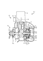
- FIG. 2 is a partial sectional view schematically showing a schematic configuration of an engine unit EU shown in FIG. 1.
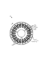
- FIG. 3 is a cross-sectional view illustrating a cross section perpendicular to a rotation axis of the generator 20 illustrated in FIG. 2.
- FIG. 2 is a block diagram showing an electrical schematic configuration of a vehicle 1 shown in FIG. 1.
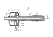
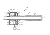
- FIG. 2 is a partially broken plan view schematically showing a part of the steering handle 8 shown in FIG. 1.
- FIG. 2 is a diagram showing a relationship between an operation amount of a grip 81 at a certain vehicle speed of the vehicle 1 shown in FIG. 1 and torques of an engine 10, a generator 20, and a crankshaft 15; It is a figure which shows the rotation angle of the grip 81 of FIG. 5 typically.
- FIG. 2 is a diagram illustrating a relationship between an operation amount of a grip 81 of the vehicle 1 illustrated in FIG. 1 and a torque of an engine 10, a torque of a generator 20, and a torque of a crankshaft 15 in a low-speed traveling mode.
- FIG. 6 is a diagram schematically illustrating a rotation angle of a grip 81 in FIG. 5 in a low-speed traveling mode.
- FIG. 9 is a partially broken plan view schematically showing a part of a steering handle 108 of a vehicle 1 according to a second embodiment of the present invention.
- FIG. 1 is an external view showing a vehicle 1 according to the first embodiment of the present invention.
- FIG. 1A shows an external view of the entire vehicle 1 of the present embodiment
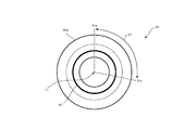
- FIG. 1B schematically shows the rotation angle of the grip 81 of the vehicle 1.
- the vehicle 1 is, for example, an engine-type straddle-type vehicle, and more specifically, is, for example, a motorcycle.
- the vehicle 1 shown in FIG. 1 includes a vehicle body 2, a steering handle 8, front wheels 3a, and rear wheels 3b.
- the steering handle 8 is rotatably attached to the vehicle body 2.
- the steering handle 8 has a grip 81.
- the front wheel 3a and the rear wheel 3b are rotatably attached to the vehicle body 2.
- the rear wheel 3b is a driving wheel.
- the vehicle 1 includes an engine unit EU, a battery 4, and a clutch 9.
- the engine unit EU is mounted on the vehicle body 2 and includes an engine 10, a generator 20, a transmission 30, and a controller 60.
- the engine 10 has a rotating crankshaft 15 and outputs power generated by combustion of gas as torque and rotation speed of the crankshaft 15.
- the generator 20 is provided so as to interlock with the crankshaft 15.
- the generator 20 is driven by the engine 10 via the crankshaft 15 to generate electric power, and receives power supply to drive the engine 10. Further, the generator 20 can also be regenerated by being driven by the rear wheel 3b, which is a driving wheel, via the crankshaft 15. That is, the generator 20 can also operate as a regenerative brake.
- Regenerative braking is a brake that uses the resistance to rotation generated by the generator's power generation as a braking force when the generator is driven by a drive wheel via a crankshaft while the output of engine power is stopped. is there. Electric power generated by the power generation is stored in a battery 4 mounted on the vehicle 1.
- the state in which the output of the engine power is stopped (the engine torque minimum state) is, for example, a state in which the supply of fuel to the engine is stopped.
- the state in which the output of the engine power is stopped includes, for example, a state in which the throttle valve is fully closed, a state in which the supply of fuel to the engine is stopped, and the throttle valve is fully closed.
- the battery 4 stores the electric power generated by the generator 20 when the generator 20 is driven by the engine 10. Battery 4 stores the power regenerated by generator 20 when generator 20 is driven by rear wheel 3b.
- the transmission 30 converts the rotation speed of the crankshaft 15 of the engine 10 and outputs the rotation to the clutch.
- the clutch 9 switches between a transmission state in which the torque of the crankshaft 15 of the engine 10 is transmitted to the rear wheel 3b and a disconnected state in which the torque is blocked.
- Control device 60 controls engine 10 and generator 20 based on the operation of the driver of vehicle 1. Control device 60 controls the power output from engine 10 and controls the braking force of vehicle 1 by controlling the amount of regeneration in generator 20.
- the vehicle 1 includes the main switch 5.
- the main switch 5 is a switch for supplying power to each part of the vehicle 1.
- the vehicle 1 includes a starter switch 6.
- the starter switch 6 is a switch for starting the engine 10.
- the vehicle 1 includes a headlight 7.
- the vehicle 1 is driven by the engine 10. Specifically, the vehicle 1 is driven by the rotational power of the engine 10 being received by the rear wheels 3 b via the transmission 30 and the clutch 9. The rotational power of the engine 10 is adjusted by operating the grip 81 with the driver's hand of the vehicle 1.
- the grip 81 is an accelerator operator for instructing acceleration and braking of the vehicle 1. That is, the grip 81 is a grip for both engine driving and regeneration operations.
- the grip 81 has a rotation angle sensor 83.
- the grip 81 is configured to be operated by the driver's hand of the vehicle 1 in the operation range from the maximum driving position ( ⁇ m) to the maximum braking position ( ⁇ b) as shown in FIG. 1B.
- the operation range of the grip 81 includes an engine driving area (X1) provided from a boundary position ( ⁇ o) located in the middle of the operation range to the maximum driving position ( ⁇ m), and a maximum braking position ( ⁇ b) from the boundary position ( ⁇ o). And a regenerative power gradually increasing region (X2) provided up to the end.
- the rotation angle of the grip 81 in part (b) of FIG. 1 will be described later.
- the engine drive region (X1) is a region set so that the control device 60 supplies fuel to the engine 10 and outputs power from the engine 10.
- the engine drive area (X1) is assigned, for example, a power that gradually increases toward the maximum drive position ( ⁇ m).
- the regenerative power gradually increasing region (X2) is set so that the control device 60 stops the supply of fuel to the engine 10 to stop the output of power by the engine 10, and the amount of power to be regenerated by the generator 20. Is a region to which a regeneration amount that gradually increases from the boundary position ( ⁇ o) toward the maximum braking position ( ⁇ b) is assigned.
- FIG. 2 is a partial cross-sectional view schematically showing a schematic configuration of the engine unit EU shown in FIG.
- the engine 10 includes a crankcase 11, a cylinder 12, a piston 13, a connecting rod 14, and a crankshaft 15.
- the piston 13 is provided in the cylinder 12 so as to be able to reciprocate.
- the crankshaft 15 is rotatably provided in the crankcase 11.
- the connecting rod 14 connects the piston 13 and the crankshaft 15.
- a cylinder head 16 is attached to an upper part of the cylinder 12.
- a combustion chamber is formed by the cylinder 12, the cylinder head 16, and the piston 13.
- the crankshaft 15 is rotatably supported by the crankcase 11 via a pair of bearings 17.
- a generator 20 is attached to a first end 15 a of the crankshaft 15.
- a transmission 30 is attached to the second end 15 b of the crankshaft 15.
- the transmission 30 is, for example, a continuously variable transmission (CVT).
- CVT continuously variable transmission
- the engine 10 is provided with a throttle valve SV, a fuel injection device 18, and a spark plug 19.
- the throttle valve SV regulates the amount of air supplied to the combustion chamber.
- the fuel injection device 18 supplies fuel to the air supplied to the combustion chamber by the throttle valve SV by injecting the fuel.
- a mixture of fuel and air is supplied to the combustion chamber.
- the ignition plug 19 burns a mixed gas of air and fuel supplied to the combustion chamber.
- the amount of fuel supplied by the fuel injection device 18 is adjusted according to the operation of the grip 81 (see FIG. 1).
- the opening of the throttle valve SV is also adjusted according to the operation of the grip 81 (see FIG. 1).
- the engine 10 is an internal combustion engine.
- the engine 10 receives supply of fuel.
- the engine 10 outputs rotational power by a combustion operation for burning fuel.
- the driver of the vehicle 1 operates the grip 81 (see FIG. 1) to adjust the rotational power output from the engine 10.
- the rotation power of the engine 10 is adjusted by, for example, adjusting the amount of fuel supplied from the fuel injection device 18 to the engine. That is, when the grip 81 is rotated in the direction of the maximum drive position ⁇ m, the supply of fuel from the fuel injection device 18 increases, and the rotational power output from the engine increases. Further, when the grip 81 is rotated in the direction of the maximum braking position ⁇ b, the supply of fuel from the fuel injection device 18 decreases, and the rotation power output from the engine decreases.
- the rotational power of the engine 10 is adjusted by adjusting the opening of the throttle valve. That is, when the grip 81 is rotated in the direction of the maximum drive position ⁇ m, the opening of the throttle valve SV increases, and the rotational power output from the engine increases. Further, when the grip 81 is rotated in the direction of the maximum braking position ⁇ b, the opening of the throttle valve SV is reduced, and the rotational power output from the engine is reduced. Adjustment of the rotational power output from the engine may be performed by adjusting both the supply of fuel by the fuel injection device 18 and the opening of the throttle valve SV.
- the adjustment of the rotational power output from the engine may be performed by combining the operation of various actuators such as a VVT and a decompression device, in addition to the supply of fuel from the fuel injection device 18 and the opening and closing of a throttle valve. .
- the engine 10 outputs rotational power via the crankshaft 15.
- the rotational power of the crankshaft 15 is transmitted to the rear wheel 3b via the transmission 30 and the clutch 9 (see FIG. 1).
- Vehicle 1 is driven by rear wheels 3 b that receive rotational power output from engine 10 via crankshaft 15.
- the engine 10 of the present embodiment is, for example, a single-cylinder four-stroke engine. That is, the engine 10 rotates the crankshaft 15 forward while repeating four strokes of the intake stroke, the compression stroke, the expansion stroke, and the exhaust stroke.
- the engine 10 of the present embodiment is an air-cooled engine. Note that the engine 10 may be a water-cooled engine or an engine having a plurality of cylinders.
- FIG. 3 is a cross-sectional view showing a cross section perpendicular to the rotation axis of the generator 20 shown in FIG. The generator 20 will be described with reference to FIGS.
- the generator 20 is a permanent magnet type three-phase brushless type generator.
- the generator 20 has a rotor 21 and a stator 22.
- the generator 20 of the present embodiment is of a radial gap type.
- the generator 20 is of an outer rotor type. That is, the rotor 21 is an outer rotor.
- the stator 22 is an inner stator.
- the rotor 21 has a rotor main body 211.
- the rotor main body 211 is made of, for example, a ferromagnetic material.
- the rotor main body 211 has a bottomed cylindrical shape.
- the rotor main body 211 has a cylindrical boss 212, a disk-shaped bottom wall 213, and a cylindrical back yoke 214.
- the bottom wall 213 and the back yoke 214 are formed integrally. Note that the bottom wall portion 213 and the back yoke portion 214 may be configured separately.
- the bottom wall portion 213 and the back yoke portion 214 are fixed to the crankshaft 15 via the cylindrical boss portion 212.
- the rotor 21 is not provided with a winding to which a current is supplied.
- the rotor 21 has a permanent magnet part 215.
- the rotor 21 has a plurality of magnetic pole portions 216.
- the plurality of magnetic pole portions 216 are formed by the permanent magnet portions 215.
- the plurality of magnetic pole portions 216 are provided on the inner peripheral surface of the back yoke portion 214.
- the permanent magnet section 215 has a plurality of permanent magnets.
- the plurality of magnetic pole portions 216 are provided for each of the plurality of permanent magnets.
- the permanent magnet portion 215 can also be formed by one annular permanent magnet.
- one permanent magnet is magnetized such that a plurality of magnetic pole portions 216 are arranged on the inner peripheral surface.
- the plurality of magnetic pole portions 216 are provided such that N poles and S poles are alternately arranged in the circumferential direction of the generator 20.
- the rotor 21 facing the stator 22 has 24 magnetic poles.
- the number of magnetic poles of the rotor 21 refers to the number of magnetic poles facing the stator 22. No magnetic material is provided between the magnetic pole part 216 and the stator 22.
- the magnetic pole portion 216 is provided around the stator 22 in the radial direction of the generator 20.
- the back yoke portion 214 is provided around the magnetic pole portion 216 in the radial direction.
- the generator 20 has more magnetic pole portions 216 than the number of the tooth portions 223.
- the rotor 21 may be an embedded magnet type (IPM type) in which the magnetic pole part 216 is embedded in a magnetic material, but as in the present embodiment, a surface magnet type in which the magnetic pole part 216 is exposed from the magnetic material. (SPM type) is preferred.
- IPM type embedded magnet type
- SPM type surface magnet type in which the magnetic pole part 216 is exposed from the magnetic material.
- a cooling fan F is provided on the bottom wall 213 of the rotor 21.
- the stator 22 has a stator core 221 and a plurality of stator windings 222.
- the stator core 221 has a plurality of teeth 223 provided at intervals in the circumferential direction.
- the plurality of tooth portions 223 integrally extend radially from the stator core 221 in a radial direction.
- a total of 18 tooth portions 223 are provided at intervals in the circumferential direction.
- the stator core 221 has a total of 18 slots 224 formed at intervals in the circumferential direction.
- the teeth 223 are arranged at equal intervals in the circumferential direction.
- the rotor 21 has a greater number of magnetic pole portions 216 than the number of the tooth portions 223.
- the number of magnetic pole portions 216 is 4/3 of the number of slots.
- stator winding 222 is wound around each tooth 223. That is, the stator windings 222 of a plurality of phases are provided so as to pass through the slots 224.
- FIG. 3 shows a state where the stator winding 222 is in the slot 224.
- Each of the plurality of stator windings 222 belongs to one of the U phase, the V phase, and the W phase.
- the stator windings 222 are arranged, for example, in the order of U-phase, V-phase, and W-phase.
- the winding of the stator winding 222 may be concentrated winding or distributed winding, and is not particularly limited, but is preferably concentrated winding.
- a plurality of detected parts 217 for detecting the rotational position of the rotor 21 are provided on the outer surface of the rotor 21.
- the plurality of detected parts 217 are detected by magnetic action.
- the plurality of detected parts 217 are provided on the outer surface of the rotor 21 at intervals in the circumferential direction.
- the detected part 217 is formed of a ferromagnetic material.
- the rotor position detecting device 218 detects the position of the rotor 21.
- the rotor position detecting device 218 is provided at a position facing the plurality of detected parts 217.
- the generator 20 is connected to the crankshaft 15 of the engine 10. Specifically, the rotor 21 is connected to the crankshaft 15 so as to rotate at a fixed speed ratio with respect to the crankshaft 15.
- the rotor 21 is attached to the crankshaft 15 without a power transmission mechanism (for example, a belt, a chain, a gear, a speed reducer, a speed increaser, etc.).
- the rotor 21 rotates at a speed ratio of 1: 1 with respect to the crankshaft 15.
- the generator 20 is configured to rotate the crankshaft 15 forward by the forward rotation of the rotor 21.
- the generator 20 may be attached to the crankshaft 15 via a power transmission mechanism. However, the generator 20 is connected to the crankshaft 15 without passing through any of a variable speed ratio transmission or a clutch. That is, the generator 20 is connected to the crankshaft 15 without going through a device whose input / output speed ratio is variable.
- the rotation axis of the generator 20 substantially coincides with the rotation axis of the crankshaft 15. Further, as in the present embodiment, it is preferable that the generator 20 is attached to the crankshaft 15 without through a power transmission mechanism.
- the generator 20 is driven by the engine 10 and operates as a generator when the engine 10 performs a combustion operation. Further, when the engine 10 stops outputting power, the generator 20 is driven by the rear wheel 3b and operates as a regenerative brake.
- the generator 20 is a radial gap type, a permanent magnet type three-phase brushless type generator having an outer rotor and an inner stator.
- the generator 20 is not limited to a permanent magnet type three-phase brushless type generator, and may be another type of generator.
- FIG. 4 is a block diagram showing a schematic electrical configuration of the vehicle 1 shown in FIG.
- the vehicle 1 includes an inverter 61.
- Control device 60 controls each part of vehicle 1 including inverter 61.
- the generator 61 and the battery 4 are connected to the inverter 61.
- the battery 4 sends and receives current to the generator 20.
- the headlight 7 is also connected to the inverter 61 and the battery 4.
- the headlight 7 is an auxiliary device mounted on the vehicle 1 that operates while consuming power.
- the headlight 7 is also referred to as an auxiliary machine 7.
- the battery 4 is connected to the inverter 61 and the headlight 7 via the main switch 5.
- a current / voltage sensor 65 is provided on a line connecting the battery 4 and the inverter 61.
- the current / voltage sensor 65 detects a current flowing through the battery 4.
- the current / voltage sensor 65 is provided between a branch point to the headlight 7 and the battery 4 in a line connecting the battery 4 and the inverter 61.
- the inverter 61 includes a plurality of switching units 611 to 616.
- the inverter 61 of the present embodiment has six switching units 611 to 616.
- the switching units 611 to 616 constitute a three-phase bridge inverter.
- the plurality of switching units 611 to 616 are connected to each phase of the multi-phase stator winding 222.
- two switching units connected in series form a half bridge.
- the switching units 611 to 616 constituting the half bridge of each phase are connected to each phase of the stator winding 222 of the plurality of phases.
- the switching units 611 to 616 switch the passage / cutoff of current between the multi-phase stator winding 222 and the battery 4.
- the generator 20 functions as a generator and a regenerative brake
- the passage / interruption of the current between each of the stator windings 222 and the battery 4 is switched by the on / off operation of the switching units 611 to 616.
- the switching units 611 to 616 By sequentially switching on / off of the switching units 611 to 616, rectification of the three-phase AC output from the generator 20 and control of the voltage are performed.
- Each of the switching units 611 to 616 has a switching element.
- the switching element is, for example, a transistor, and more specifically, an FET (Field Effect Transistor).
- FET Field Effect Transistor
- a thyristor and an IGBT Insulated Gate Bipolar Transistor
- a current sensor (not shown) is provided on a line connecting the inverter 61 and the stator winding 222.
- the current sensor detects a current in the generator 20.
- the current sensor is connected to the control device 60.
- the control device 60 is connected with the rotation angle sensor 83 of the grip 81, the throttle valve SV, the fuel injection device 18, the spark plug 19, and the battery 4.
- the control device 60 includes a power generation control unit 62 and an engine control unit 63.
- the power generation control unit 62 controls the operation of the generator 20 by controlling the on / off operation of each of the switching units 611 to 616.
- the engine control unit 63 controls the combustion operation of the engine 10 by controlling the throttle valve SV, the fuel injection device 18, and the spark plug 19, and controls the rotational power of the engine 10.
- the control device 60 is constituted by a computer having a central processing unit (not shown) and a storage device (not shown).
- the central processing unit performs arithmetic processing based on the control program.
- the storage device stores programs and data relating to operations.
- the power generation control unit 62 and the engine control unit 63 are realized by a computer (not shown) and a control program executed by the computer. Therefore, the operation of each of the power generation control unit 62 and the engine control unit 63, which will be described below, can be said to be the operation of the control device 60.
- the power generation control unit 62 and the engine control unit 63 may be configured as separate devices, for example, at positions separated from each other, or may be configured integrally.
- the starter switch 6 is connected to the control device 60.
- the starter switch 6 is operated by the driver when the engine 10 is started.
- the power generation control unit 62 of the control device 60 detects the charge level of the battery 4.
- the power generation control unit 62 detects the charge level of the battery 4 by detecting the voltage and the current of the battery 4.
- the main switch 5 supplies power to the control device 60 according to the operation.
- the power generation control unit 62 and the engine control unit 63 of the control device 60 control the engine 10 and the generator 20 based on the electric signal from the rotation angle sensor 83 of the grip 81.
- the power generation control unit 62 controls the inverter 61. Specifically, when the grip 81 is located in the engine driving area, the engine control unit 63 controls the engine 10, and when the grip 81 is located in the regenerative power gradually increasing area, the power generation control unit 62 controls the inverter 61. By doing so, the generator 20 is controlled.
- FIG. 5 is a partially broken plan view schematically showing a part of the steering handle 8 of the present embodiment.
- the steering handle 8 in FIG. 5 includes a handlebar 80, a grip 81, and a housing 82.
- the grip 81 is rotatably provided near the first end of the handlebar 80 of the steering handle 8.
- the housing 82 is provided on the handlebar 80. Inside the housing 82, accommodating portions 82a and 82b are partitioned by rib-shaped protrusions 82c.
- the grip 81 includes a tube guide portion 81b and a grip portion 81a.
- the tube guide portion 81b of the grip 81 is formed at the end of the grip 81 in the vehicle width direction (the left-right direction in the drawing).
- the tube guide portion 81b is housed in the housing portion 82a of the housing 82 so as to be rotatable relative to the housing 82.
- the grip 81a is arranged outside the housing 82.
- the grip 81 is configured to be rotatable relative to the housing 82.
- the grip 81 is set so as to be rotatable within a predetermined range around the rotation axis L1. That is, the grip 81 is set so that it cannot rotate beyond the predetermined range.
- the position where the grip 81 is rotated to the maximum in the acceleration direction is defined as the maximum drive position ⁇ m (see FIG. 7).
- the position where the grip 81 is rotated to the maximum in the direction opposite to the acceleration direction is defined as the maximum braking position ⁇ b (see FIG. 7).
- a rotation angle sensor 83 is provided in the housing portions 82a and 82b of the housing 82.
- the rotation angle sensor 83 is configured to detect a relative rotation angle of the grip 81 with respect to the housing 82.
- a potentiometer is used as the rotation angle sensor 83.
- a pinion gear 83a is attached to the rotation angle sensor 83.
- the pinion gear 83a is linked to the rotation angle sensor 83 so as to be rotatable around an axis parallel to the rotation axis L1.
- the pinion gear 83a meshes with and interlocks with a sector gear 81c integrally formed with the tube guide portion 81b.
- the rotation angle sensor 83 can detect the rotation angle of the grip 81.
- the rotation angle sensor 83 is provided adjacent to the tube guide portion 81b of the grip 81.
- the rotation angle sensor 83 is connected to the control device 60 by a detection signal wiring 83b.
- a biasing member 84 is provided in the housing portion 82b of the housing 82. In a state where the driver does not apply an operation force to the grip 81, the urging member 84 positions the grip 81 at the maximum braking position ⁇ b. The urging member 84 rotates the grip 81 in a direction to return the grip 81 to the maximum braking position ⁇ b while the driver is applying an operation force to the grip 81 in the direction toward the maximum drive position ⁇ m (see FIG. 7).
- a spring is mainly used for the urging member 84. More specifically, a torsion spring, a coil spring, or the like is used for the biasing member 84. However, a biasing member other than a spring may be used.
- FIG. 6 is a diagram showing a relationship between the operation amount of the grip 81 at a certain vehicle speed of the vehicle shown in FIG. 1 and the torque of the engine 10, the torque of the generator 20, and the torque of the crankshaft 15.
- the position where the operation amount of the grip 81 is 100% is defined as the maximum drive position ⁇ m.
- the position where the grip operation amount is 0% is defined as the maximum braking position ⁇ b.
- a boundary position ⁇ o at which power output by the engine 10 is stopped is provided.
- the movable rotation angle range of the grip 81 is divided into two regions: a region from the boundary position ⁇ o to the maximum driving position ⁇ m, and a region from the boundary position ⁇ o to the maximum braking position ⁇ b.
- An area from the boundary position ⁇ o of the grip 81 to the maximum drive position ⁇ m is set as an engine drive area X1.
- An area from the boundary position ⁇ o of the grip 81 to the maximum braking position ⁇ b is set as a regenerative force gradually increasing area X2.
- the control device 60 increases the power output from the engine 10 and increases the engine torque (area X1 (see broken line W1). Then, the vehicle driving force by engine 10 increases, and vehicle 1 is accelerated. At the maximum drive position ⁇ m, the control device 60 maximizes the power output from the engine 10 (makes the power output from the engine the maximum power at the current rotational speed). When the driver gradually rotates the grip 81 from the maximum drive position ⁇ m to the boundary position ⁇ o, the control device 60 gradually reduces the power output from the engine 10 and lowers the engine torque (broken line in the region X1). W1).
- the control device 60 stops the output of power by the engine 10.
- the stop of power output by the engine 10 is created by the control device 60 stopping the supply of fuel by the fuel injection device 18.
- the power output by the engine 10 may be stopped by, for example, completely closing the throttle valve SV of the engine 10 instead of stopping the fuel supply by the fuel injection device 18 by the control device 60.
- the stop of power output by the engine 10 is created by the control device 60 fully closing the throttle valve SV of the engine 10 and stopping the supply of fuel by the fuel injection device 18. You may.
- control device 60 gradually reduces the amount of regeneration by the generator 20. (See the dashed line W3 in the region X2). That is, control device 60 gradually increases the amount of power generated by generator 20 in a state where power output by engine 10 is stopped, thereby gradually increasing the absolute value of motor torque by generator 20. Thus, control device 60 operates generator 20 as a regenerative brake, and gradually increases the braking force applied to crankshaft 15.
- the control device 60 gradually reduces the absolute value of the motor torque of the generator 20 while the output of the power by the engine 10 is stopped. Let me do it. Then, while the engine torque of the engine 10 acts on the crankshaft 15 as the braking force (see the broken line W1 in the region X2), the braking force by the generator 20 acting on the crankshaft 15 gradually decreases (the dashed line in the region X2). W3).
- the regenerative braking by the power generation of the generator 20 is activated substantially when the output of the power by the engine 10 is stopped. Then, the braking force acting on the crankshaft 15 increases continuously from the engine driving area X1 to the regenerative power gradually increasing area X2. Thus, in the present embodiment, the braking force can be smoothly increased with respect to the operation of the grip 81 performed by the driver's hand.
- the vehicle 1 of the present embodiment uses the regenerative braking by the generator 20 in the regenerative power gradually increasing region X2 when a strong braking force is required. Thereby, the vehicle 1 of the present embodiment can obtain a strong braking force.
- a vehicle uses a friction brake with a brake pad when a strong braking force is required.
- a strong braking force can be obtained without relying on the friction brake by the brake pad. Therefore, the vehicle 1 can reduce the wear of the brake pad.
- FIG. 7 is a diagram schematically showing the rotation angle of the grip 81 of FIG.
- the grip 81 is configured to be rotatable between the maximum driving position ⁇ m, the boundary position ⁇ o, and the maximum braking position ⁇ b.
- the grip 81 is configured to be operated by the driver's hand of the vehicle 1 in an operable range from the maximum driving position ⁇ m to the maximum braking position ⁇ b.
- the position where the grip 81 is rotated to the maximum in the acceleration direction is the maximum drive position ⁇ m.
- the position where the grip 81 is rotated to the maximum in the opposite direction to the acceleration direction is the maximum braking position ⁇ b.
- the boundary position ⁇ o of the grip 81 is located in the middle of the operable range of the grip.
- the region from the boundary position ⁇ o of the grip 81 to the maximum drive position ⁇ m is the engine drive region X1.
- a region from the boundary position ⁇ o of the grip 81 to the maximum braking position ⁇ b is a regenerative force gradually increasing region X2.
- the engine drive area X1 and the regenerative power gradually increasing area X2 can be set in consideration of the characteristics of the engine and the generator, and further, the preference of the driver.
- the engine drive region X1 can be set to occupy 90% of the whole, and the regenerative power gradually increasing region X2 can be set to occupy the remaining 10%. That is, the area from the boundary position ⁇ o to the maximum driving position ⁇ m occupies 90% of the rotation area of the grip 81 (the area from the maximum driving position ⁇ m to the maximum braking position ⁇ b), and the area from the boundary position ⁇ o to the maximum braking position ⁇ b.
- the area can be set so as to occupy 10% of the rotation area of the grip 81 (the area from the maximum driving position ⁇ m to the maximum braking position ⁇ b).
- the grip 81 is normally adjusted by an urging member 84 (see FIG. 5) provided inside the housing 82 so as to be arranged at the maximum braking position ⁇ b. That is, when no operation force is applied to the grip 81, the grip 81 is located at the maximum braking position ⁇ b.
- the grip 81 when the grip 81 is rotated from the maximum braking position ⁇ b to the maximum driving position ⁇ m, the stress is accumulated in the biasing member 84. After the driver grips the grip 81 and rotates the grip 81 from the maximum braking position ⁇ b toward the maximum driving position ⁇ m, when the driver releases the grip 81, the grip 81 returns to the maximum braking position ⁇ b.
- the boundary position ⁇ o can be configured to be set according to at least one parameter related to the traveling of the vehicle 1.
- the at least one parameter may include a speed of the vehicle 1.
- the boundary position ⁇ o is set to the same position as the maximum braking position ⁇ b. In this setting, the regenerative power gradually increasing region X2 disappears, and the regeneration by the generator 20 is not performed.
- the control device 60 stops the output of power by the engine 10.
- the control device 60 increases the power output by the engine 10.
- the boundary position ⁇ o is set between the maximum braking position ⁇ b and the maximum driving position ⁇ m, and the regenerative force gradually increasing region X2 exists.
- the vehicle 1 may have a feeling of waiting to open the accelerator when starting.
- the boundary position ⁇ o is fixed, the driving force does not act on the crankshaft 15 unless the grip 81 is rotated to the boundary position ⁇ o. This is because the output of power by the engine 10 remains stopped in the regenerative power gradually increasing region X2.
- the setting may be made such that the setting of the boundary position ⁇ o is changed depending on whether or not it exceeds a low-speed reference value (a reference value of the vehicle speed of the vehicle 1 during low-speed traveling).
- the low speed reference value is a value set in advance.
- the low speed reference value is, for example, a value within a range from 10 km / h to less than 20 km / h.
- the “boundary position ⁇ o” is set between the “maximum driving position ⁇ m” and the “maximum braking position ⁇ b”.
- This running state is referred to as a normal running mode.
- the driver of the vehicle 1 can use the regenerative brake by operating the grip 81.
- the “boundary position ⁇ o” is set to the same position as the “maximum braking position ⁇ b”.
- This running state is referred to as a low-speed running mode.
- the grip 81 is used only for adjusting the power output by the engine 10. Further, the control device 60 sets so that the output of power by the engine 10 is stopped when the grip 81 is located at the maximum braking position ⁇ b. Therefore, the adjustment of the regeneration amount by the grip operation is not performed.
- the driver of the vehicle 1 can use the friction brake using the brake pad.
- the control device 60 can switch between the normal traveling mode and the low-speed traveling mode based on the low-speed reference value set in a range where the vehicle speed is 10 km / h or more and less than 20 km / h.
- a transition mode may be provided in which the boundary position ⁇ o gradually moves toward the maximum braking position ⁇ b as the vehicle 1 decelerates from when the vehicle speed falls below the low speed reference value. Thereby, the vehicle 1 can smoothly perform the operation at the time of switching between the low-speed traveling mode and the normal traveling mode.
- the operation area of the grip 81 in the low-speed traveling mode will be described in detail.
- the operation area of the grip 81 in the normal traveling mode is as described in FIGS. 6 and 7.
- FIG. 8 is a diagram showing the relationship between the amount of operation of the grip 81 at a certain vehicle speed of the vehicle shown in FIG. 1 and the torque of the engine 10, the torque of the generator 20, and the torque of the crankshaft 15 in the low-speed running mode.
- the position where the operation amount of the grip 81 is 100% is defined as the maximum drive position ⁇ m.
- the position where the grip operation amount is 0% is defined as the maximum braking position ⁇ b.
- the boundary position ⁇ o at which the output of power by the engine 10 is stopped is the same as the maximum braking position ⁇ b.
- the movable rotation angle range of the grip 81 is a range from the boundary position ⁇ o to the maximum braking position ⁇ b. In the low-speed traveling mode, the entire region from the maximum braking position ⁇ b to the maximum driving position ⁇ m of the grip 81 is set as the engine driving region X1.
- the control device 60 gradually increases the power output from the engine 10 and increases the engine torque. (See broken line W1). Then, the vehicle driving force by engine 10 increases, and vehicle 1 is accelerated. At the maximum drive position ⁇ m, the control device 60 maximizes the power output from the engine 10 (makes the power output from the engine the maximum power at the current rotational speed). When the driver gradually rotates the grip 81 from the maximum driving position ⁇ m to the maximum braking position ⁇ b, the control device 60 gradually decreases the power by the engine 10 and lowers the engine torque (see the broken line W1 in the area X1). ). Then, the vehicle driving force by engine 10 decreases, and vehicle 1 decelerates. At the maximum braking position ⁇ b, the control device 60 stops the output of power by the engine 10.
- FIG. 9 is a diagram schematically showing the rotation angle of the grip 81 of FIG. 5 in the low-speed traveling mode.
- the grip 81 is configured to be rotatable between a maximum driving position ⁇ m and a maximum braking position ⁇ b.
- the grip 81 is configured to be operated by the driver's hand of the vehicle 1 in an operable range from the maximum driving position ⁇ m to the maximum braking position ⁇ b.
- the position where the grip 81 is rotated to the maximum in the acceleration direction is the maximum drive position ⁇ m.
- the position where the grip 81 is rotated to the maximum in the direction opposite to the acceleration is the maximum braking position ⁇ b.
- the driver of the vehicle 1 puts his hand on the grip 81 and grips the grip 81. When the driver flexes his wrist, the grip 81 moves to the maximum drive position ⁇ m. When the driver buckles his wrist, the grip 81 moves toward the maximum braking position ⁇ b. This is the same as the description with reference to FIG.
- FIG. 10 is a partially broken plan view schematically showing a part of the steering handle 108 of the vehicle 1 according to the second embodiment of the present invention.
- the steering handle 108 of the vehicle 1 is different from the steering handle 8 of the vehicle 1 of the first embodiment.
- the steering handle 108 in FIG. 10 includes a handlebar 180, a grip 181 and a housing 182.
- the grip 181 is rotatably provided near a first end of the handlebar 180 of the steering handle 108.
- the housing 182 is provided on the handlebar 180. Inside the housing 182, housing portions 182a and 182b are partitioned by rib-shaped projections 182c.
- the grip 181 includes a tube guide 181b and a grip 181a.
- the tube guide portion 181b of the grip 181 is formed at the end of the grip 181 in the vehicle width direction (the left-right direction in the drawing).
- the tube guide portion 181b is housed in the housing portion 182a of the housing 182 in a state where the tube guide portion 181b is rotatable relative to the housing 182.
- the grip 181a is arranged outside the housing 182.
- the grip 181 is configured to be rotatable relative to the housing 182.
- the grip 181 is set to be rotatable within a predetermined range around the rotation axis L1. That is, the grip 181 is set so that it cannot rotate beyond the predetermined range.
- the position at which the grip 181 is rotated in the forward direction of the driver to the maximum is defined as the maximum drive position ⁇ m.
- the position where the grip 181 is rotated to the maximum in the vehicle traveling direction is defined as the maximum braking position ⁇ b.
- a rotation angle sensor 183 is provided in the housing portions 182a and 182b of the housing 182.
- the rotation angle sensor 183 is configured to detect a relative rotation angle of the grip 181 with respect to the housing 182.
- a potentiometer is used as the rotation angle sensor 183.
- the rotation angle sensor 183 is provided with a pinion gear 183a that is linked to the rotation angle sensor 183 so as to be rotatable around an axis parallel to the rotation axis L1.
- the pinion gear 183a meshes with and interlocks with a sector gear 181c integrally formed with the tube guide 181b.
- the rotation angle sensor 183 can detect the rotation angle of the grip 181.
- the rotation angle sensor 183 is provided to face the tube guide 181b of the grip 181.
- the rotation angle sensor 183 is connected to the control device 60 by a detection signal wiring 183b.
- a third urging member 185a and a second urging member 185b are provided in the housing portion 182b of the housing 182.
- the third biasing member 185a biases the grip 181 from the maximum drive position ⁇ m toward the boundary position ⁇ o.
- the second urging member 185b urges the grip 181 from the maximum braking position ⁇ b toward the boundary position ⁇ o.
- the third urging member 185a and the second urging member 185b move the grip 181 to the boundary position. Rotate in the direction to return to ⁇ o.
- the third urging member 185a and the second urging member 185b position the grip 181 at the boundary position ⁇ o.
- the third urging member 185a and the second urging member 185b mainly use springs. More specifically, a torsion spring, a coil spring, or the like is used as the third urging member 185a and the second urging member 185b.
- the third biasing member 185a and the second biasing member 185b may employ a biasing member other than a spring.
- the grip 181 After the grip 181 is rotated from the boundary position ⁇ o to the maximum drive position ⁇ m, when the driver of the vehicle 1 decreases the grip on the grip 181, the grip 181 returns to the boundary position ⁇ o. After the grip 181 is rotated from the boundary position ⁇ o to the maximum braking position ⁇ b, when the driver of the vehicle 1 reduces the grip on the grip 181, the grip 181 returns to the boundary position ⁇ o.
- the driver of the vehicle 1 can adjust the strength of the braking force by operating the grip 181. For example, if a strong braking force is not required, the driver can use only the engine brake. In this case, the driver rotates the grip 181 from the engine driving area X1 to the boundary position ⁇ o. At this time, the driver returns the grip 181 to the boundary position ⁇ o or weakens the gripping force of the grip 181. Then, the grip 181 returns to the boundary position ⁇ o. At the boundary position ⁇ o, the engine brake works on the vehicle 1, but the regenerative brake does not work on the vehicle 1. Therefore, a strong braking force does not act on the vehicle 1.
- the driver can use the regenerative braking by the generator 20 in addition to the engine braking by the engine 10.
- the driver rotates the grip 181 from the boundary position ⁇ o to the maximum braking position ⁇ b.
- regenerative braking by the generator 20 acts on the vehicle 1 in addition to engine braking by the engine 10. Therefore, a strong braking force acts on the vehicle 1.
- the driver can arbitrarily select the use of the regenerative brake by actively applying the operation force.
- the boundary position ⁇ o is not set so as to change according to the vehicle speed of the vehicle 1.
- the grip 181 is located at the boundary position ⁇ o in a state where the operation force by the driver's hand is not applied. Therefore, at the time of starting, the driving force of the engine 10 acts on the crankshaft 15 even if the operation amount of the grip 181 is small. Therefore, the vehicle 1 according to the present embodiment does not have a feeling of waiting for the opening of the throttle when starting.
- the first embodiment is different from the steering wheel 8 of the vehicle 1, and the low-speed running mode is not set as in the first embodiment.
- the present embodiment and the first embodiment are common except for the above difference.
Landscapes
- Engineering & Computer Science (AREA)
- Mechanical Engineering (AREA)
- Steering Devices For Bicycles And Motorcycles (AREA)
- Electric Propulsion And Braking For Vehicles (AREA)
- Control Of Vehicle Engines Or Engines For Specific Uses (AREA)
Abstract
本発明は、運転者の手により行われるグリップの操作に伴う制動力を、操作に対し滑らかに増大することができるエンジン式鞍乗型車両を提供することを目的とする。 エンジン式鞍乗型車両は、運転者の手で最大駆動位置から最大制動位置までの操作範囲で操作されるエンジン駆動及び回生の両方を操作するためのグリップを備える。グリップの操作範囲は、操作範囲の途中に位置する境界位置から最大駆動位置まで設けられ、制御装置にエンジンへの燃料の供給を行わせ、エンジンからパワーを出力させるように設定されるエンジン駆動領域と、境界位置から最大制動位置まで設けられ、制御装置にエンジンへの燃料の供給を停止させるように設定されるとともに、発電機での回生量として境界位置から最大制動位置に向かって徐々に増大する回生量が割り当てられる回生力漸増領域とを有する。
Description
本発明は、エンジン式鞍乗型車両に関する。
例えば、特許文献1には、エンジンの動力で走行するエンジン式鞍乗型車両として、自動2輪車が示されている。特許文献1に示されたエンジン式鞍乗型車両では、アクセルグリップがステアリングハンドルに設けられている。運転者は、エンジン式鞍乗型車両を加速させるために、アクセルグリップを操作する。
エンジン式鞍乗型車両は、アクセルグリップの操作に応じてエンジンから出力されるパワーを増大することにより加速する。たとえば、エンジン式鞍乗型車両がリーンしながらコーナーを旋回しているときに、運転者が、アクセルグリップを操作してエンジン式鞍乗型車両を加速させることにより、エンジン式鞍乗型車両がリーン状態から直立状態に復帰する。
運転者は、例えば、走行中のエンジン式鞍乗型車両を停止させるために、エンジン式鞍乗型車両を減速させる。また、例えば、エンジン式鞍乗型車両がコーナーをリーン状態で走行しやすいように、運転者は、エンジン式鞍乗型車両がコーナーに入るときにエンジン式鞍乗型車両を減速させる。運転者は、エンジン式鞍乗型車両を減速させるために、ブレーキパッドによる摩擦ブレーキのほかに、エンジンによるエンジンブレーキを使用することができる。運転者は、エンジン式鞍乗型車両を減速させるためにアクセルグリップを加速時とは反対方向に操作することで作動するエンジンによるエンジンブレーキを使用する。また、エンジンブレーキ以上の制動力を更に必要とする場合、運転者は、ブレーキレバーやブレーキペダルを操作して、ブレーキパッドによる摩擦ブレーキを使用する。
エンジンブレーキは、エンジン式鞍乗型車両の走行中に、アクセルグリップの操作を加速時とは反対方向に戻すことにより作動する。エンジンブレーキによる制動力は、アクセルグリップを戻したときに生じる、エンジンのポンピングロスや部材同士の摩擦に起因する。エンジン式鞍乗型車両は、減速時の操作簡素化のためアクセルグリップ操作のみでの制動力を従来以上に発生させることができ、かつ運転者の操作に対して滑らかに制動力が増大することが望まれている。
従って、本発明の目的は、従来のエンジンブレーキ以上の制動力を、アクセルグリップの操作に応じて滑らかに増大することができるエンジン式鞍乗型車両を提供することである。
本発明のエンジン式鞍乗型車両は、次の構成を備える。
(1)
エンジン式鞍乗型車両であって、
前記エンジン式鞍乗型車両は、
回転するクランク軸を有し、ガスの燃焼によって生じるパワーを前記クランク軸のトルク及び回転速度として出力するエンジンと、
前記エンジンから出力されたパワーによって駆動される駆動輪と、
前記クランク軸と連動するよう設けられ、前記駆動輪に駆動されることにより回生するとともに、
発電機と、
前記発電機で回生又は発電された電力を蓄えるバッテリと、
前記エンジン及び前記発電機を制御する制御装置であって、前記エンジンから出力されるパワーを制御するとともに、前記発電機での回生量を制御することにより前記エンジン式鞍乗型車両の制動力を制御する制御装置と、
前記エンジン式鞍乗型車両のステアリングハンドルに設けられた、エンジン駆動及び回生の両方の操作のためのグリップであって、前記エンジン式鞍乗型車両の運転者の手で最大駆動位置から最大制動位置までの操作範囲で操作されるように構成され、前記操作範囲は、前記操作範囲の途中に位置する境界位置から前記最大駆動位置まで設けられたエンジン駆動領域と、前記境界位置から前記最大制動位置まで設けられた回生力漸増領域とを有し、前記エンジン駆動領域は、前記制御装置に前記エンジンへの燃料の供給を行わせ、前記エンジンからパワーを出力させるように設定された領域であり、前記回生力漸増領域は、前記制御装置に前記エンジンへの燃料の供給を停止させるように設定されるとともに、前記発電機での回生量として前記境界位置から前記最大制動位置に向かって徐々に増大する回生量が割り当てられた領域である、グリップと、
を備えたエンジン式鞍乗型車両。
(1)
エンジン式鞍乗型車両であって、
前記エンジン式鞍乗型車両は、
回転するクランク軸を有し、ガスの燃焼によって生じるパワーを前記クランク軸のトルク及び回転速度として出力するエンジンと、
前記エンジンから出力されたパワーによって駆動される駆動輪と、
前記クランク軸と連動するよう設けられ、前記駆動輪に駆動されることにより回生するとともに、
発電機と、
前記発電機で回生又は発電された電力を蓄えるバッテリと、
前記エンジン及び前記発電機を制御する制御装置であって、前記エンジンから出力されるパワーを制御するとともに、前記発電機での回生量を制御することにより前記エンジン式鞍乗型車両の制動力を制御する制御装置と、
前記エンジン式鞍乗型車両のステアリングハンドルに設けられた、エンジン駆動及び回生の両方の操作のためのグリップであって、前記エンジン式鞍乗型車両の運転者の手で最大駆動位置から最大制動位置までの操作範囲で操作されるように構成され、前記操作範囲は、前記操作範囲の途中に位置する境界位置から前記最大駆動位置まで設けられたエンジン駆動領域と、前記境界位置から前記最大制動位置まで設けられた回生力漸増領域とを有し、前記エンジン駆動領域は、前記制御装置に前記エンジンへの燃料の供給を行わせ、前記エンジンからパワーを出力させるように設定された領域であり、前記回生力漸増領域は、前記制御装置に前記エンジンへの燃料の供給を停止させるように設定されるとともに、前記発電機での回生量として前記境界位置から前記最大制動位置に向かって徐々に増大する回生量が割り当てられた領域である、グリップと、
を備えたエンジン式鞍乗型車両。
(1)のエンジン式鞍乗型車両は、エンジンと、駆動輪と、発電機と、バッテリと、制御装置と、グリップとを備える。エンジンは、回転するクランク軸を有し、ガスの燃焼によって生じるパワーをクランク軸のトルク及び回転速度として出力する。駆動輪は、エンジンから出力されたパワーによって駆動される。発電機は、クランク軸と連動するよう設けられ、駆動輪に駆動されることにより回生するとともに、エンジンにより駆動されることにより発電する。バッテリは、発電機で回生された電力を蓄える。
制御装置は、エンジン及び発電機を制御する。制御装置は、エンジンから出力されるパワーを制御するとともに、発電機での回生量を制御することによりエンジン式鞍乗型車両の制動力を制御する。
グリップは、エンジン式鞍乗型車両の操向用のステアリングハンドルに設けられ、エンジン駆動及び回生の両方の操作をおこなう。グリップは、エンジン式鞍乗型車両の運転者の手で最大駆動位置から最大制動位置までの操作範囲で操作されるように構成される。グリップの操作範囲は、操作範囲の途中に位置する境界位置から最大駆動位置まで設けられたエンジン駆動領域と、境界位置から最大制動位置まで設けられた回生力漸増領域とを有する。エンジン駆動領域は、制御装置にエンジンへの燃料の供給を行わせ、エンジンからパワーを出力させるように設定された領域である。回生力漸増領域は、制御装置にエンジンへの燃料の供給を停止させるように設定されるとともに、発電機での回生量として境界位置から最大制動位置に向かって徐々に増大する回生量が割り当てられた領域である。
制御装置は、エンジン及び発電機を制御する。制御装置は、エンジンから出力されるパワーを制御するとともに、発電機での回生量を制御することによりエンジン式鞍乗型車両の制動力を制御する。
グリップは、エンジン式鞍乗型車両の操向用のステアリングハンドルに設けられ、エンジン駆動及び回生の両方の操作をおこなう。グリップは、エンジン式鞍乗型車両の運転者の手で最大駆動位置から最大制動位置までの操作範囲で操作されるように構成される。グリップの操作範囲は、操作範囲の途中に位置する境界位置から最大駆動位置まで設けられたエンジン駆動領域と、境界位置から最大制動位置まで設けられた回生力漸増領域とを有する。エンジン駆動領域は、制御装置にエンジンへの燃料の供給を行わせ、エンジンからパワーを出力させるように設定された領域である。回生力漸増領域は、制御装置にエンジンへの燃料の供給を停止させるように設定されるとともに、発電機での回生量として境界位置から最大制動位置に向かって徐々に増大する回生量が割り当てられた領域である。
(1)のエンジン式鞍乗型車両は、グリップの操作範囲にエンジン駆動領域と回生力漸増領域とを設定している。(1)のエンジン式鞍乗型車両は、
回生力漸増領域において徐々に発電機による回生量を増大する。発電機による制動力は、電気的に制御することができる。これにより、運転者の手で行われるグリップの操作に伴う制動力を、操作に対し滑らかに増大することができる。このため、回生力漸増領域での制動力を滑らかに増大することができる。
回生力漸増領域において徐々に発電機による回生量を増大する。発電機による制動力は、電気的に制御することができる。これにより、運転者の手で行われるグリップの操作に伴う制動力を、操作に対し滑らかに増大することができる。このため、回生力漸増領域での制動力を滑らかに増大することができる。
(2) (1)のエンジン式鞍乗型車両であって、
前記グリップは、前記操作の力が与えられない状態で前記グリップを前記最大制動位置に位置させ、前記最大駆動位置へ向かう方向へ前記操作の力が与えられているときに前記グリップを前記最大制動位置へ戻す方向へ回転させるように設けられた付勢部材を備える。
前記グリップは、前記操作の力が与えられない状態で前記グリップを前記最大制動位置に位置させ、前記最大駆動位置へ向かう方向へ前記操作の力が与えられているときに前記グリップを前記最大制動位置へ戻す方向へ回転させるように設けられた付勢部材を備える。
(2)のエンジン式鞍乗型車両は、減速させる場合に、運転者が、回転させたグリップの操作力を操作力が与えられない状態まで減少することで、エンジンブレーキ作動時の制動力を滑らかに増大することができる。(2)のエンジン式鞍乗型車両に係る付勢部材としては、例えば、後述する第1付勢部材が挙げられる。
(3) (1)のエンジン式鞍乗型車両であって、
前記グリップは、前記最大駆動位置又は前記最大制動位置へ向かう方向へ前記操作の力が与えられているときに前記グリップを前記境界位置へ戻す方向へ回転させ、前記操作の力が与えられない状態で前記グリップを前記境界位置に位置させるように設けられた付勢部材を備える。
前記グリップは、前記最大駆動位置又は前記最大制動位置へ向かう方向へ前記操作の力が与えられているときに前記グリップを前記境界位置へ戻す方向へ回転させ、前記操作の力が与えられない状態で前記グリップを前記境界位置に位置させるように設けられた付勢部材を備える。
(3)のエンジン式鞍乗型車両は、減速させる場合に、運転者が付勢部材の付勢力に反してグリップを積極的に操作することにより制動力の強弱を調整することができる。(3)のエンジン式鞍乗型車両に係る付勢部材としては、例えば、後述する第2付勢部材及び第3付勢部材が挙げられる。また、1つの付勢部材が設けられてもよい。
(4) (1)又は(2)のエンジン式鞍乗型車両であって、
前記グリップは、前記エンジン式鞍乗型車両の走行に関する少なくとも1つのパラメータに応じて、前記境界位置が設定されるように構成されている。
前記グリップは、前記エンジン式鞍乗型車両の走行に関する少なくとも1つのパラメータに応じて、前記境界位置が設定されるように構成されている。
(4)のエンジン式鞍乗型車両によれば、走行状態に応じて、エンジン駆動領域の回転角度範囲と、回生力漸増領域の回転角度範囲との比率を変更できる。例えば、停止時乃至低速時にエンジン駆動領域を広げることができる。高速時に回生力漸増領域を広げることができる。加速時にエンジン駆動領域を広げることができる。減速時に回生力漸増領域を広げることができる。このように、(4)のエンジン式鞍乗型車両は、エンジン駆動領域及び回生力漸増領域の各々について、走行状態に適した大きさの領域を提供できる。なお、エンジン式鞍乗型車両の走行に関するパラメータとしては、特に限定されず、例えば、車速、トルク、加速度、エンジン回転速度、変速段等が挙げられる。
(5) (4)のエンジン式鞍乗型車両であって、
前記エンジン式鞍乗型車両の走行に関する少なくとも1つのパラメータは、車速を含んでおり、
前記グリップは、前記車速がゼロであるときに、前記境界位置が前記最大制動位置と同じ位置に設定され且つ前記回生力漸増領域が無く、前記車速が上昇すると、前記回生力漸増領域が存在するように前記最大制動位置と前記最大駆動位置との間に前記境界位置が設定されるように構成されている。
前記エンジン式鞍乗型車両の走行に関する少なくとも1つのパラメータは、車速を含んでおり、
前記グリップは、前記車速がゼロであるときに、前記境界位置が前記最大制動位置と同じ位置に設定され且つ前記回生力漸増領域が無く、前記車速が上昇すると、前記回生力漸増領域が存在するように前記最大制動位置と前記最大駆動位置との間に前記境界位置が設定されるように構成されている。
(5)のエンジン式鞍乗型車両は、発進時にグリップの操作量が少なくても、クランク軸にエンジンによる駆動力が働くようにできる。このため、発進時に、グリップの操作を開始した後のエンジンのパワーを出力するまでの時間を短縮できる。また、車速が上昇すると、回生力漸増領域が設けられるので、制動力を滑らかに増大することができる。
(6) (5)のエンジン式鞍乗型車両であって、
前記境界位置は、前記車速が低速基準値よりも小さい低速走行状態で、前記境界位置が前記最大制動位置と同じ位置に設定されるように、前記車速に応じて設定され、
前記境界位置が前記最大制動位置と同じ位置に設定される場合、前記最大制動位置で前記発電機による回生は行われない。
前記境界位置は、前記車速が低速基準値よりも小さい低速走行状態で、前記境界位置が前記最大制動位置と同じ位置に設定されるように、前記車速に応じて設定され、
前記境界位置が前記最大制動位置と同じ位置に設定される場合、前記最大制動位置で前記発電機による回生は行われない。
(6)のエンジン式鞍乗型車両は、例えば発進時のような低速走行状態でグリップの操作量が少なくても、クランク軸に発電機による回生ブレーキが働くことなく、エンジンによる駆動力が働くようにできる。
(7) (1)乃至(3)のいずれか1つのエンジン式鞍乗型車両であって、
前記エンジンは、前記エンジンに供給されるガスの量を制御するスロットル弁を備え、
前記制御装置は、前記グリップの前記境界位置において、前記スロットル弁を全閉にさせる。
前記エンジンは、前記エンジンに供給されるガスの量を制御するスロットル弁を備え、
前記制御装置は、前記グリップの前記境界位置において、前記スロットル弁を全閉にさせる。
(7)のエンジン式鞍乗型車両では、制御装置がスロットル弁を境界位置において全閉にする。したがって、制御装置は、境界位置において、スロットル弁が開いているときよりもエンジンブレーキの制動力を強く作動させることができる。
本明細書にて使用される専門用語は特定の実施例のみを定義する目的であって発明を制限する意図を有しない。本明細書にて使用される用語「及び/又は」はひとつの、又は複数の関連した列挙された構成物のあらゆる又はすべての組み合わせを含む。本明細書中で使用される場合、用語「含む、備える(including)」「含む、備える(comprising)」又は「有する(having)」及びその変形の使用は、記載された特徴、工程、操作、要素、成分及び/又はそれらの等価物の存在を特定するが、ステップ、動作、要素、コンポーネント、及び/又はそれらのグループのうちの1つ又は複数を含むことができる。本明細書中で使用される場合、用語「取り付けられた」、「接続された」、「結合された」及び/又はそれらの等価物は広く使用され、直接的及び間接的な取り付け、接続及び結合の両方を包含する。さらに、「接続された」及び「結合された」は、物理的又は機械的な接続又は結合に限定されず、直接的又は間接的な電気的接続又は結合を含むことができる。他に定義されない限り、本明細書で使用される全ての用語(技術用語及び科学用語を含む)は、本発明が属する当業者によって一般的に理解されるのと同じ意味を有する。一般的に使用される辞書に定義された用語のような用語は、関連する技術及び本開示の文脈における意味と一致する意味を有すると解釈されるべきであり、本明細書で明示的に定義されていない限り、理想的又は過度に形式的な意味で解釈されることはない。本発明の説明においては、技術及び工程の数が開示されていると理解される。これらの各々は個別の利益を有し、それぞれは、他の開示された技術の1つ以上、又は、場合によっては全てと共に使用することもできる。したがって、明確にするために、この説明は、不要に個々のステップの可能な組み合わせをすべて繰り返すことを控える。それにもかかわらず、明細書及び特許請求の範囲は、そのような組み合わせがすべて本発明及び請求項の範囲内にあることを理解して読まれるべきである。
本明細書では、新しいエンジン式鞍乗型車両について説明する。以下の説明では、説明の目的で、本発明の完全な理解を提供するために多数の具体的な詳細を述べる。しかしながら、当業者には、これらの特定の詳細なしに本発明を実施できることが明らかである。本開示は、本発明の例示として考慮されるべきであり、本発明を以下の図面又は説明によって示される特定の実施形態に限定することを意図するものではない。
エンジンは、例えば、単気筒エンジン及び2以上の気筒を有するエンジンを含む。エンジンは、ガソリンエンジンであってもよく、ディーゼルエンジンであってもよい。
発電機は、発電動作が可能な回転電機である。発電機は、例えば、発電とモータ動作が可能な回転電機であってもよい。また、発電機は、例えば、エンジンを始動する始動発電機の機能を備えていてもよい。発電機は、アウターロータ型でもよく、また、インナーロータ型でもよい。また、発電機は、ラジアルギャップ型でなく、アキシャルギャップ型でもよい。
鞍乗型車両(straddled vehicle)とは、運転者がサドルに跨って着座する形式の車両をいう。鞍乗型車両としては、例えば、スクータ型、モペット型、オフロード型、オンロード型の自動二輪車が挙げられる。また、鞍乗型車両としては、自動二輪車に限定されず、例えば、自動三輪車であってもよい。自動三輪車は、2つの前輪と1つの後輪とを備えていてもよく、1つの前輪と2つの後輪とを備えていてもよい。
エンジン式鞍乗型車両は、エンジンから出力されたパワーによって走行する車両である。エンジン式鞍乗型車両では、エンジンから出力された回転力が駆動輪に伝達される。
駆動輪は、後輪であってもよく、前輪であってもよい。また、駆動輪は、後輪及び前輪の双方であってもよい。
回生とは、発電機による回生ブレーキをいう。発電機による回生ブレーキは、エンジンのパワーの出力が停止した状態において、駆動輪により発電機が駆動された時に、発電により生じる発電機の回転抵抗を制動力に利用したブレーキである。発電により生じた電力は、エンジン式鞍乗型車両に搭載されたバッテリに蓄積される。また、回生量とは、発電機を回生ブレーキとして動作させたときに、発電により生じた電力量をいう。
本発明によれば、エンジン式鞍乗型車両の運転者の手により行われるグリップの操作に伴う制動力を、操作に対し滑らかに増大することができる。
以下、本発明を、好ましい実施形態に基づいて図面を参照しつつ説明する。
[第1の実施形態]
図1は、本発明の第1の実施形態に係る
車両1を示す外観図である。ここで、図1パート(a)は、本実施形態の車両1の全体の外観図を示し、図1パート(b)は、車両1のグリップ81の回転角度を模式的に示す図である。車両1は、例えば、エンジン式鞍乗型車両、さらに詳細には、例えば、自動2輪車である。
図1は、本発明の第1の実施形態に係る
車両1を示す外観図である。ここで、図1パート(a)は、本実施形態の車両1の全体の外観図を示し、図1パート(b)は、車両1のグリップ81の回転角度を模式的に示す図である。車両1は、例えば、エンジン式鞍乗型車両、さらに詳細には、例えば、自動2輪車である。
図1に示す車両1は、車体2と、ステアリングハンドル8と、前輪3aと、後輪3bとを備える。ステアリングハンドル8は、車体2に回転可能に取り付けられている。ステアリングハンドル8は、グリップ81を備えている。前輪3a及び後輪3bは、車体2に回転可能に取り付けられている。後輪3bは、駆動輪である。
車両1は、エンジンユニットEUと、バッテリ4と、クラッチ9とを備える。エンジンユニットEUは、車体2に搭載され、エンジン10と、発電機20と、変速装置30と、制御装置60とを備える。エンジン10は、回転するクランク軸15を有し、ガスの燃焼によって生じるパワーをクランク軸15のトルク及び回転速度として出力する。発電機20は、クランク軸15と連動するよう設けられている。発電機20は、クランク軸15を介してエンジン10に駆動され発電するとともに、電力の供給を受けてエンジン10を駆動する。また、発電機20は、クランク軸15を介して駆動輪である後輪3bにより駆動されることにより回生することもできる。すなわち、発電機20は、回生ブレーキとしても動作することもできる。回生ブレーキは、エンジンのパワーの出力が停止した状態において、発電機がクランク軸を介して駆動輪に駆動されたとき、発電機の発電により生じた回転への抵抗を制動力に利用したブレーキである。発電により生じた電力は、車両1に搭載されたバッテリ4に蓄積される。なお、エンジンのパワーの出力が停止した状態(エンジントルクミニマム状態)は、例えば、エンジンへの燃料の供給を停止した状態があげられる。また、エンジンのパワーの出力が停止した状態は、他に、例えばスロットル弁を全閉にした状態、及びエンジンへの燃料の供給を停止してスロットル弁を全閉にした状態等もあげられる。
バッテリ4は、エンジン10によって発電機20が駆動される場合に発電機20で発電された電力を蓄える。バッテリ4は、後輪3bによって発電機20が駆動される場合に発電機20で回生された電力を蓄える。変速装置30は、エンジン10が有するクランク軸15の回転速度を変換してクラッチに出力する。クラッチ9は、エンジン10が有するクランク軸15の回転力を後輪3bへ伝達する伝達状態と、回転力を遮断する遮断状態とを切り替える。
制御装置60は、車両1の運転者の操作に基づいてエンジン10及び発電機20を制御する。制御装置60は、エンジン10から出力されるパワーを制御するとともに、発電機20での回生量を制御することにより車両1の制動力を制御する。
車両1は、メインスイッチ5を備えている。メインスイッチ5は、車両1の各部に電力を供給するためのスイッチである。車両1は、スタータスイッチ6を備えている。スタータスイッチ6は、エンジン10を始動するためのスイッチである。車両1は、前照灯7を備えている。
車両1は、エンジン10によって駆動される。具体的には、車両1は、変速装置30及びクラッチ9を介してエンジン10の回転パワーを後輪3bが受けることによって駆動される。エンジン10の回転パワーは、車両1の運転者の手によってグリップ81を操作することにより、調整される。
グリップ81は、車両1の加速及び制動を指示するためのアクセル操作子である。すなわち、グリップ81は、エンジン駆動及び回生の両方の操作のためのグリップである。グリップ81は、回転角度センサ83を有している。グリップ81は、図1パート(b)に示すように車両1の運転者の手で最大駆動位置(θm)から最大制動位置(θb)までの操作範囲で操作されるように構成されている。グリップ81の操作範囲は、操作範囲の途中に位置する境界位置(θo)から最大駆動位置(θm)まで設けられたエンジン駆動領域(X1)と、境界位置(θo)から最大制動位置(θb)まで設けられた回生力漸増領域(X2)とを有している。なお、図1のパート(b)のグリップ81の回転角度については、のちに説明する。
ここで、エンジン駆動領域(X1)には、制御装置60にエンジン10への燃料の供給を行わせ、エンジン10からパワーを出力させるように設定された領域である。エンジン駆動領域(X1)は、例えば最大駆動位置(θm)に向かって徐々に増大するパワーが割り当てられている。また、回生力漸増領域(X2)は、制御装置60にエンジン10への燃料の供給を停止させてエンジン10によるパワーの出力を停止させるように設定されるとともに、発電機20での回生させる量として境界位置(θo)から最大制動位置(θb)に向かって徐々に増大する回生量が割り当てられた領域である。
図2は、図1に示すエンジンユニットEUの概略構成を模式的に示す部分断面図である。
エンジン10は、クランクケース11と、シリンダ12と、ピストン13と、コネクティングロッド14と、クランク軸15とを備えている。ピストン13は、シリンダ12内に往復移動自在に設けられている。
クランク軸15は、クランクケース11内に回転可能に設けられている。コネクティングロッド14は、ピストン13とクランク軸15を接続している。シリンダ12の上部には、シリンダヘッド16が取り付けられている。シリンダ12とシリンダヘッド16とピストン13とによって、燃焼室が形成される。クランク軸15は、クランクケース11に、一対のベアリング17を介して、回転自在な態様で支持されている。クランク軸15の第1の端部15aには、発電機20が取り付けられている。クランク軸15の第2の端部15bには、変速装置30が取り付けられている。変速装置30は、例えば無段変速機(CVT)である。
エンジン10には、スロットル弁SVと、燃料噴射装置18と、点火プラグ19とが設けられている。スロットル弁SVは、燃焼室に供給される空気の量を調整する。燃料噴射装置18は、燃料を噴射することによって、スロットル弁SVにより燃焼室に供給される空気に燃料を供給する。燃料と空気の混合ガスが、燃焼室に供給される。点火プラグ19は、燃焼室に供給される空気と燃料の混合ガスを燃焼させる。燃料噴射装置18による燃料の供給量は、グリップ81(図1参照)の操作に応じて調整される。スロットル弁SVの開度についても、グリップ81(図1参照)の操作に応じて調整される。
エンジン10は、内燃機関である。エンジン10は、燃料の供給を受ける。エンジン10は、燃料を燃焼する燃焼動作によって回転パワーを出力する。車両1の運転者は、グリップ81(図1参照)を操作することによって、エンジン10から出力される回転パワーを調節する。エンジン10の回転パワーの調整は、一例として、燃料噴射装置18からエンジンへ供給する燃料の量を調整することによって行う。すなわち、グリップ81を最大駆動位置θm方向に回転させると、燃料噴射装置18からの燃料の供給が増加し、エンジンから出力される回転パワーが増大する。また、グリップ81を最大制動位置θb方向に回転させると、燃料噴射装置18からの燃料の供給が減少し、エンジンから出力される回転パワーが減少する。また、他の例としては、エンジン10の回転パワーの調整は、スロットル弁の開度を調整することによって行う。すなわち、グリップ81を最大駆動位置θm方向に回転させると、スロットル弁SVの開度が大きくなり、エンジンから出力される回転パワーが増大する。また、グリップ81を最大制動位置θb方向に回転させると、スロットル弁SVの開度を小さくなり、エンジンから出力される回転パワーが減少する。また、エンジンから出力される回転パワーの調整は、燃料噴射装置18による燃料の供給とスロットル弁SVの開度との双方を調整することにより行ってもよい。さらに、エンジンから出力される回転パワーの調整は、燃料噴射装置18からの燃料の供給、スロットル弁の開閉の他、VVT及びデコンプレッション装置等の様々なアクチュエータの操作を組み合わせることにより行ってもよい。
エンジン10は、クランク軸15を介して回転パワーを出力する。クランク軸15の回転パワーは、変速装置30及びクラッチ9(図1参照)を介して、後輪3bに伝達される。車両1は、クランク軸15を介してエンジン10から出力される回転パワーを受ける後輪3bによって駆動される。
本実施形態のエンジン10は、例えば単気筒の4ストロークエンジンである。すなわち、エンジン10は、吸気行程、圧縮行程、膨張行程、及び排気行程の4行程を繰返しながらクランク軸15を正回転させる。本実施形態のエンジン10は、空冷型エンジンである。なお、エンジン10は、水冷型エンジンであってもよく、また複数の気筒を備えたエンジンであってもよい。
図3は、図2に示す発電機20の回転軸線に垂直な断面を示す断面図である。図2及び図3を参照して発電機20を説明する。
発電機20は、永久磁石式三相ブラシレス型発電機である。発電機20は、ロータ21と、ステータ22とを有する。本実施形態の発電機20は、ラジアルギャップ型である。発電機20は、アウターロータ型である。即ち、ロータ21はアウターロータである。ステータ22はインナーステータである。
ロータ21は、ロータ本体部211を有する。ロータ本体部211は、例えば強磁性材料からなる。ロータ本体部211は、有底筒状を有する。ロータ本体部211は、筒状ボス部212と、円板状の底壁部213と、筒状のバックヨーク部214とを有する。底壁部213及びバックヨーク部214は一体的に形成されている。なお、底壁部213とバックヨーク部214とは別体に構成されていてもよい。底壁部213及びバックヨーク部214は筒状ボス部212を介してクランク軸15に固定されている。ロータ21には、電流が供給される巻線が設けられていない。
ロータ21は、永久磁石部215を有する。ロータ21は、複数の磁極部216を有する。複数の磁極部216は永久磁石部215により形成されている。複数の磁極部216は、バックヨーク部214の内周面に、設けられている。本実施形態において、永久磁石部215は、複数の永久磁石を有する。複数の磁極部216は、複数の永久磁石のそれぞれに設けられている。
なお、永久磁石部215は、1つの環状の永久磁石によって形成されることも可能である。この場合、1つの永久磁石は、複数の磁極部216が内周面に並ぶように着磁される。
複数の磁極部216は、発電機20の周方向にN極とS極とが交互に配置されるように設けられている。本実施形態では、ステータ22と対向するロータ21の磁極数が24個である。ロータ21の磁極数とは、ステータ22と対向する磁極数をいう。磁極部216とステータ22との間には磁性体が設けられていない。
磁極部216は、発電機20の径方向におけるステータ22の周囲に設けられている。バックヨーク部214は、径方向における磁極部216の周囲に設けられている。発電機20は、歯部223の数よりも多い磁極部216を有している。
なお、ロータ21は、磁極部216が磁性材料に埋め込まれた埋込磁石型(IPM型)であってもよいが、本実施形態のように、磁極部216が磁性材料から露出した表面磁石型(SPM型)であることが好ましい。
ロータ21を構成する底壁部213には、冷却ファンFが設けられている。
ステータ22は、ステータコア221と複数のステータ巻線222とを有する。ステータコア221は、周方向に間隔を空けて設けられた複数の歯部223を有する。複数の歯部223は、ステータコア221から径方向に放射状に一体的に延びている。本実施形態においては、合計18個の歯部223が周方向に間隔を空けて設けられている。換言すると、ステータコア221は、周方向に間隔を空けて形成された合計18個のスロット224を有する。歯部223は周方向に等間隔で配置されている。
ロータ21は、歯部223の数より多い数の磁極部216を有する。磁極部216の数は、スロット数の4/3である。
各歯部223の周囲には、ステータ巻線222が巻回している。つまり、複数相のステータ巻線222は、スロット224を通るように設けられている。図3には、ステータ巻線222が、スロット224の中にある状態が示されている。複数相のステータ巻線222のそれぞれは、U相、V相、W相の何れかに属する。ステータ巻線222は、例えば、U相、V相、W相の順に並ぶように配置される。ステータ巻線222の巻き方は、集中巻きであっても、分布巻きであってもよく、特に限定されないが、集中巻きであることが好ましい。
ロータ21の外面には、ロータ21の回転位置を検出させるための複数の被検出部217が備えられている。複数の被検出部217は、磁気作用によって検出される。複数の被検出部217は、周方向に間隔を空けてロータ21の外面に設けられている。被検出部217は、強磁性体で形成されている。
ロータ位置検出装置218は、ロータ21の位置を検出する装置である。ロータ位置検出装置218は、複数の被検出部217と対向する位置に設けられている。
発電機20は、エンジン10のクランク軸15と接続されている。詳細には、ロータ21が、クランク軸15に対し固定された速度比で回転するようクランク軸15と接続されている。
本実施形態では、ロータ21が、クランク軸15に、動力伝達機構(例えば、ベルト、チェーン、ギア、減速機、増速機等)を介さずに取り付けられている。ロータ21は、クランク軸15に対し1:1の速度比で回転する。発電機20が、ロータ21の正回転によりクランク軸15を正回転させるように構成されている。
なお、発電機20は、クランク軸15に、動力伝達機構を介して取り付けられていてもよい。ただし、発電機20は、速度比可変の変速機又はクラッチのいずれも介することなく、クランク軸15に接続される。即ち、発電機20は、入出力の速度比が可変の装置を介することなく、クランク軸15に接続される。
なお、本実施形態においては、発電機20の回転軸線と、クランク軸15の回転軸線とが略一致していることが好ましい。また、本実施形態のように、発電機20が動力伝達機構を介さずにクランク軸15に取り付けられていることが好ましい。
発電機20は、エンジン10が燃焼動作する場合に、エンジン10に駆動されて発電機として動作する。また、発電機20は、エンジン10がパワーの出力を停止した場合に、後輪3bに駆動されて回生ブレーキとして動作する。
図3において、発電機20は、ラジアルギャップ型、アウターロータ及びインナーステータを有する永久磁石式三相ブラシレス型発電機としている。しかし、本実施形態において、発電機20は、永久磁石式三相ブラシレス型発電機に限定されることはなく、他の形態の発電機であってもよい。
図4は、図1に示す車両1の電気的な概略構成を示すブロック図である。車両1は、インバータ61を備える。制御装置60は、インバータ61を含む車両1の各部を制御する。
インバータ61には、発電機20とバッテリ4とが接続されている。バッテリ4は、発電機20に対し電流の授受を行う。インバータ61及びバッテリ4には、前照灯7も接続されている。前照灯7は、電力を消費しながら動作する、車両1に搭載された補機である。以降、前照灯7を補機7とも称する。
バッテリ4は、メインスイッチ5を介して、インバータ61及び前照灯7と接続されている。バッテリ4とインバータ61とを接続するラインには、電流・電圧センサ65が設けられている。電流・電圧センサ65は、バッテリ4に流れる電流を検出する。電流・電圧センサ65は、バッテリ4とインバータ61とを接続するラインのうち、前照灯7への分岐点とバッテリ4との間に設けられている。
インバータ61は、複数のスイッチング部611~616を備えている。本実施形態のインバータ61は、6個のスイッチング部611~616を有する。スイッチング部611~616は、三相ブリッジインバータを構成している。複数のスイッチング部611~616は、複数相のステータ巻線222の各相と接続されている。
より詳細には、複数のスイッチング部611~616のうち、直列に接続された2つのスイッチング部がハーフブリッジを構成している。各相のハーフブリッジを構成するスイッチング部611~616は、複数相のステータ巻線222の各相とそれぞれ接続されている。スイッチング部611~616は、複数相のステータ巻線222とバッテリ4との間の電流の通過/遮断を切替える。
詳細には、発電機20がモータとして機能する場合、スイッチング部611~616のオン・オフ動作によって複数相のステータ巻線222のそれぞれに対する通電及び通電停止が切替えられる。
また、発電機20が発電機及び回生ブレーキとして機能する場合、スイッチング部611~616のオン・オフ動作によって、ステータ巻線222のそれぞれとバッテリ4との間の電流の通過/遮断が切替えられる。スイッチング部611~616のオン・オフが順次切替えられることによって、発電機20から出力される三相交流の整流及び電圧の制御が行われる。
スイッチング部611~616のそれぞれは、スイッチング素子を有する。スイッチング素子は、例えばトランジスタであり、より詳細にはFET(Field Effect Transistor)である。ただし、スイッチング部611~616には、FET以外に、例えばサイリスタ及びIGBT(Insulated Gate Bipolar Transistor)も採用可能である。
インバータ61とステータ巻線222とを接続するラインには、電流センサ(不図示)が設けられている。電流センサは、発電機20における電流を検出する。電流センサは、制御装置60に接続されている。
制御装置60には、グリップ81の回転角度センサ83と、スロットル弁SVと、燃料噴射装置18と、点火プラグ19と、バッテリ4とが接続されている。制御装置60は、発電制御部62と、エンジン制御部63とを備えている。
発電制御部62は、スイッチング部611~616のそれぞれのオン・オフ動作を制御することによって、発電機20の動作を制御する。エンジン制御部63は、スロットル弁SVと、燃料噴射装置18と、点火プラグ19とを制御することによって、エンジン10の燃焼動作を制御して、エンジン10の回転パワーを制御する。
制御装置60は、図示しない中央処理装置と、図示しない記憶装置とを有するコンピュータで構成されている。中央処理装置は、制御プログラムに基づいて演算処理を行う。記憶装置は、プログラム及び演算に関するデータを記憶する。発電制御部62と、エンジン制御部63とは、図示しないコンピュータとコンピュータで実行される制御プログラムとによって実現される。従って、以降説明する、発電制御部62と、エンジン制御部63とのそれぞれによる動作は、制御装置60の動作と言うことができる。なお、発電制御部62及びエンジン制御部63は、例えば互いに別の装置として互いに離れた位置に構成されてもよく、また、一体に構成されるものであってもよい。
制御装置60には、スタータスイッチ6が接続されている。スタータスイッチ6は、エンジン10の始動の際、運転者によって操作される。制御装置60の発電制御部62は、バッテリ4の充電レベルを検出する。発電制御部62は、バッテリ4の電圧及び電流を検出することによってバッテリ4の充電レベルを検出する。メインスイッチ5は、操作に応じて制御装置60に電力を供給する。
制御装置60の発電制御部62及びエンジン制御部63は、グリップ81の回転角度センサ83からの電気信号に基づいて、エンジン10及び発電機20を制御する。発電制御部62は、インバータ61を制御する。具体的には、グリップ81がエンジン駆動領域に位置するときは、エンジン制御部63がエンジン10を制御し、グリップ81が回生力漸増領域に位置するときは、発電制御部62がインバータ61を制御することにより発電機20を制御する。
図5は、本実施形態のステアリングハンドル8の一部を模式的に示す部分破断平面図である。
図5のステアリングハンドル8は、ハンドルバー80と、グリップ81と、筐体82とを備えている。グリップ81は、ステアリングハンドル8のハンドルバー80の第1の端部付近に回転可能に設けられている。筐体82は、ハンドルバー80に設けられている。筐体82内部は、収容部82a及び82bが、リブ状の突起部82cにより区画されている。
グリップ81は、チューブガイド部81bと、把持部81aとを備える。グリップ81のチューブガイド部81bは、グリップ81の、車幅方向(図中、左右方向)の端部に形成されている。チューブガイド部81bは、筐体82に対して相対回転可能な状態で、筐体82の収容部82aに収容されている。把持部81aは、筐体82の外部に配置される。グリップ81は、筐体82と相対回転可能に構成されている。
グリップ81は、回転軸線L1を中心として所定範囲内で回転可能であるように設定される。つまり、グリップ81は、所定範囲以上回転できないように設定される。グリップ81を加速方向に最大限回転させた位置を最大駆動位置θm(図7参照)とする。グリップ81を加速方向とは逆方向に最大限回転させた位置を最大制動位置θb(図7参照)とする。
筐体82の収容部82a及び82bには、回転角度センサ83が設けられている。回転角度センサ83は、グリップ81の筐体82に対する相対回転角度を検出するように構成されている。回転角度センサ83としては、例えばポテンショメータが使用される。回転角度センサ83には、ピニオンギヤ83aが取り付けられている。ピニオンギヤ83aは、回転軸線L1と平行な軸回りに回転自在となるよう回転角度センサ83に連動連結されている。ピニオンギヤ83aは、チューブガイド部81bと一体成形されているセクタギヤ81cと噛合い連動する。これにより回転角度センサ83はグリップ81の回転角度を検出できる。回転角度センサ83は、グリップ81のチューブガイド部81bに隣接して設けられている。回転角度センサ83は、検出信号用配線83bにより、制御装置60と接続されている。
筐体82の収容部82bには、付勢部材84が設けられている。運転者がグリップ81に操作の力を与えない状態では、付勢部材84は、グリップ81を最大制動位置θbに位置させる。運転者がグリップ81に最大駆動位置θm(図7参照)へ向かう方向への操作の力を与えているときに、付勢部材84は、グリップ81を最大制動位置θbへ戻す方向へ回転させる。付勢部材84には、主にばねが使用される。さらに具体的には、付勢部材84には、ねじりばね、コイルばね等が使用される。ただし、ばね以外の付勢部材を採用しても構わない。
図6は、図1に示す車両のある車速におけるグリップ81の操作量と、エンジン10のトルク、発電機20のトルク及びクランク軸15のトルクとの関係を示す図である。
本実施形態において、グリップ81の操作量が100%の位置を、最大駆動位置θmとする。また、グリップの操作量が0%の位置を、最大制動位置θbとする。グリップ81の操作可能範囲の途中に、エンジン10によるパワーの出力を停止させる境界位置θoが設けられている。
グリップ81の可動回転角度域は、境界位置θoから最大駆動位置θmまでの領域と、境界位置θoから最大制動位置θbまでの領域との2つの領域に分割される。グリップ81の境界位置θoから最大駆動位置θmまでの領域を、エンジン駆動領域X1と設定する。グリップ81の境界位置θoから最大制動位置θbまでの領域を、回生力漸増領域X2と設定する。
エンジン駆動領域X1において、運転者がグリップ81を境界位置θoから最大駆動位置θmまで徐々に回転させると、制御装置60は、エンジン10から出力されるパワーを増加させ、エンジントルクを上昇させる(領域X1の破線W1参照)。そうすると、エンジン10による車両駆動力が増加し、車両1は加速される。最大駆動位置θmにおいて、制御装置60は、エンジン10から出力されるパワーを最大にする(エンジンから出力されるパワーを現回転数における最大パワーにする)。また、運転者がグリップ81を最大駆動位置θmから境界位置θoまで徐々に回転させると、制御装置60はエンジン10から出力されるパワーを徐々に減少させ、エンジントルクを下降させる(領域X1の破線W1参照)。そうすると、エンジン10による車両駆動力が減少し、車両1は減速する。境界位置θoにおいて、制御装置60は、エンジン10によるパワーの出力を停止させる。本実施形態において、エンジン10によるパワーの出力の停止は、制御装置60が、燃料噴射装置18による燃料の供給を停止することにより作り出す。また、エンジン10によるパワーの出力の停止は、例えば、制御装置60が、燃料噴射装置18による燃料の供給を停止する代わりに、エンジン10のスロットル弁SVを全閉にすることにより作り出してもよい。さらに、例えば、エンジン10によるパワーの出力の停止は、本実施形態において、制御装置60が、エンジン10のスロットル弁SVを全閉にして、燃料噴射装置18による燃料の供給を停止することにより作り出してもよい。
一方で、回生力漸増領域X2においては、運転者が、グリップを境界位置θoから最大制動位置θbまで車両進行方向に徐々に回転させると、制御装置60は、発電機20による回生量を徐々に増大する(領域X2の一点鎖線W3参照)。すなわち、制御装置60が、エンジン10によるパワーの出力を停止した状態で、発電機20による発電量を徐々に増大することにより、発電機20によるモータトルクの絶対値を徐々に増大する。これによって、制御装置60は、発電機20を回生ブレーキとして作動させて、クランク軸15に与える制動力を徐々に増大する。
運転者がグリップを最大制動位置θbから境界位置θoまで徐々に回転させると、制御装置60は、エンジン10によるパワーの出力を停止した状態で、発電機20のモータトルクの絶対値を徐々に減少させていく。そうすると、クランク軸15にエンジン10によるエンジントルクが制動力として働いている間(領域X2の破線W1参照)、クランク軸15に働く発電機20による制動力が徐々に減少する(領域X2の一点鎖線W3参照)。
運転者がグリップを最大制動位置θbから境界位置θoまで徐々に回転させると、制御装置60は、エンジン10によるパワーの出力を停止した状態で、発電機20のモータトルクの絶対値を徐々に減少させていく。そうすると、クランク軸15にエンジン10によるエンジントルクが制動力として働いている間(領域X2の破線W1参照)、クランク軸15に働く発電機20による制動力が徐々に減少する(領域X2の一点鎖線W3参照)。
発電機20の発電による回生ブレーキは、実質的にエンジン10によるパワーの出力が停止した時点から作動する。そうすると、エンジン駆動領域X1から回生力漸増領域X2にかけて、クランク軸15に働く制動力が連続して増大する。これにより、本実施形態は、運転者の手で行われるグリップ81の操作に対し、制動力を滑らかに増大することができる。
本実施形態の車両1は、強い制動力が必要なときに、回生力漸増領域X2において、発電機20による回生ブレーキを使用する。これにより、本実施形態の車両1は、強い制動力を得ることができる。通常、車両は、強い制動力が必要なときは、ブレーキパッドによる摩擦ブレーキを使用する。しかし、車両1は、発電機20による回生ブレーキを使用することができるため、ブレーキパッドによる摩擦ブレーキに頼らなくとも強い制動力が得られる。従って、車両1は、ブレーキパッドの摩耗を少なくすることができる。
図7は、図5のグリップ81の回転角度を模式的に示した図である。グリップ81は、最大駆動位置θmから境界位置θoを通って最大制動位置θbまでの間で回転可能に構成されている。グリップ81は、車両1の運転者の手で最大駆動位置θmから最大制動位置θbまでの操作可能範囲で操作されるように構成されている。グリップ81を加速方向に最大限回転させた位置が最大駆動位置θmになる。グリップ81を加速方向とは逆に最大限回転させた位置が最大制動位置θbになる。グリップ81の境界位置θoは、グリップの操作可能範囲の途中に配置される。グリップ81の境界位置θoから最大駆動位置θmまでの領域が、エンジン駆動領域X1である。グリップ81の境界位置θoから最大制動位置θbまでの領域が、回生力漸増領域X2である。
車両1の運転者はグリップ81の上から手をかけて、グリップ81を握る。運転者が手首を背屈させると、グリップ81は最大駆動位置θmに向かう。運転者が手首を掌屈させると、グリップ81は最大制動位置θbに向かう。
ここで、グリップ81において、エンジン駆動領域X1及び回生力漸増領域X2は、エンジン及び発電機の特性、さらには運転者の好みを考慮して設定することが可能である。本実施形態においては、例えば、エンジン駆動領域X1を全体の90%を占めるように設定し、回生力漸増領域X2を残りの10%を占めるように設定することができる。つまり、境界位置θoから最大駆動位置θmまでの領域が、グリップ81の回転領域(最大駆動位置θmから最大制動位置θbまでの領域)の90%を占め、境界位置θoから最大制動位置θbまでの領域が、グリップ81の回転領域(最大駆動位置θmから最大制動位置θbまでの領域)の10%を占めるように設定することができる。
グリップ81は、筐体82内部に設けられた付勢部材84(図5参照)により、通常、最大制動位置θbに配置されるように調整されている。すなわち、グリップ81に操作力が与えられない状態では、グリップ81は最大制動位置θbに位置する。
言い換えると、グリップ81を最大制動位置θbから最大駆動位置θmまで回転させると、付勢部材84には応力が蓄えられる。運転者がグリップ81を握って、最大制動位置θbから最大駆動位置θmに向かってグリップ81を回転させたのち、運転者がグリップ81から手を離すと、グリップ81は最大制動位置θbに戻る。
本実施形態において、境界位置θoは、車両1の走行に関する少なくとも1つのパラメータに応じて設定されるように構成することができる。少なくとも1つのパラメータは、車両1の車速を含んでいてもよい。例えば、車両1の車速がゼロであるときに、境界位置θoは、最大制動位置θbと同じ位置に設定される。この設定のとき、回生力漸増領域X2はなくなり、発電機20による回生は行われない。グリップ81が最大制動位置θb(境界位置θo)において、制御装置60は、エンジン10によるパワーの出力を停止する。また、グリップ81が最大制動位置θb(境界位置θo)から最大駆動位置θmへ回転されると、制御装置60は、エンジン10によるパワーの出力を増加させる。
一方で、車両1の車速が上昇すると、境界位置θoは、最大制動位置θbと最大駆動位置θmとの間に設定され、回生力漸増領域X2が存在するようになる。これは、車両1の車速がゼロであるときに、境界位置θoを最大制動位置θbと同じ位置に設定しないと、車両1に発進時におけるアクセルの開け待ち感が生じてしまうからである。車両1の発進時において、例えば境界位置θoが固定されたままであると、グリップ81を境界位置θoまで回転させないと、駆動力がクランク軸15に働かないからである。これは、回生力漸増領域X2においては、エンジン10によるパワーの出力が停止したままであるからである。
また、本実施形態において、境界位置θoは、低速基準値(低速走行時における車両1の車速の基準値)を超えるか否かにより設定が変更されるように構成することができる。低速基準値は、予め設定される値である。低速基準値は、例えば10km/h以上20km/h未満の範囲内の値である。
具体的には、まず、車両1の車速が低速基準値よりも高い高速走行状態においては、「境界位置θo」が「最大駆動位置θm」と「最大制動位置θb」との間に設定されるように構成する。この走行状態を、通常走行モードとする。通常走行モードにおいては、車両1の運転者は、グリップ81の操作により、回生ブレーキを使用することができる。
次に、車両1の車速が低速基準値よりも小さい低速走行状態においては、「境界位置θo」が「最大制動位置θb」と同じ位置に設定される。この走行状態を、低速走行モードとする。低速走行モードにおいては、グリップ81はエンジン10によるパワーの出力の調整のみに使用される。また、制御装置60は、グリップ81が最大制動位置θbに位置したときに、エンジン10によるパワーの出力を停止するように設定する。そのため、グリップ操作による回生量の調整は行われない。
なお、低速走行モードにおいて制動力が必要なとき、車両1の運転者は、ブレーキパッドを用いた摩擦ブレーキを使用することができる。
制御装置60は、車速が10km/h以上20km/h未満の範囲で設定される低速基準値を基準として、通常走行モードと低速走行モードとを切り替えることができる。このとき、車速が低速基準値を下回ったときから、車両1が減速するに従って、境界位置θoが、最大制動位置θbに向かって徐々に移動するように設定された移行モードを設けてもよい。これにより、車両1は、低速走行モードと通常走行モードとの切り替わり時の動作をスムーズに行うことができる。
以下、低速走行モードのグリップ81の操作領域について、詳細に説明する。なお、通常走行モードのグリップ81の操作領域については、図6及び図7に記載した通りである。
図8は、低速走行モードにおける、図1に示す車両のある車速におけるグリップ81の操作量と、エンジン10のトルク、発電機20のトルク及びクランク軸15のトルクとの関係を示す図である。
本実施形態において、グリップ81の操作量が100%の位置を、最大駆動位置θmとする。また、グリップの操作量が0%の位置を、最大制動位置θbとする。エンジン10によるパワーの出力を停止する境界位置θoは、最大制動位置θbと同じ位置になる。
グリップ81の可動回転角度域は、境界位置θoから最大制動位置θbまでの領域である。低速走行モードにおいては、グリップ81の最大制動位置θbから最大駆動位置θmまでの領域すべてをエンジン駆動領域X1と設定する。
エンジン駆動領域X1において、運転者がグリップ81を最大制動位置θbから最大駆動位置θmまで徐々に回転させると、制御装置60は、エンジン10から出力されるパワーを徐々に増加させ、エンジントルクを上昇させる(破線W1参照)。そうすると、エンジン10による車両駆動力が増加し、車両1は加速される。最大駆動位置θmにおいて、制御装置60は、エンジン10から出力されるパワーを最大にする(エンジンから出力されるパワーを現回転数における最大パワーにする)。また、運転者がグリップ81を最大駆動位置θmから最大制動位置θbまで徐々に回転させると、制御装置60はエンジン10によるパワーを徐々に減少させ、エンジントルクを下降させる(領域X1の破線W1参照)。そうすると、エンジン10による車両駆動力が減少し、車両1は減速する。最大制動位置θbにおいて、制御装置60は、エンジン10によるパワーの出力を停止させる。
図9は、低速走行モードにおける、図5のグリップ81の回転角度を模式的に示した図である。グリップ81は、最大駆動位置θmから最大制動位置θbまでの間で回転可能に構成されている。グリップ81は、車両1の運転者の手で最大駆動位置θmから最大制動位置θbまでの操作可能範囲で操作されるように構成されている。グリップ81を加速方向に最大限回転させた位置が最大駆動位置θmになる。グリップ81を加速とは逆方向に最大限回転させた位置が最大制動位置θbになる。車両1の運転者はグリップ81の上から手をかけて、グリップ81を握る。運転者が手首を背屈させると、グリップ81は最大駆動位置θmに向かう。運転者が手首を掌屈させると、グリップ81は最大制動位置θbに向かう。このことは、図7を参照した説明と同じである。
[第2の実施形態]
図10は、本発明の第2の実施形態に係る車両1のステアリングハンドル108の一部を模式的に示す部分破断平面図である。本発明の第2の実施形態は、車両1のステアリングハンドル108が、第1の実施形態の車両1のステアリングハンドル8と異なっている。
図10は、本発明の第2の実施形態に係る車両1のステアリングハンドル108の一部を模式的に示す部分破断平面図である。本発明の第2の実施形態は、車両1のステアリングハンドル108が、第1の実施形態の車両1のステアリングハンドル8と異なっている。
図10のステアリングハンドル108は、ハンドルバー180と、グリップ181と、筐体182とを備えている。グリップ181は、ステアリングハンドル108のハンドルバー180の第1の端部付近に回転可能に設けられている。筐体182は、ハンドルバー180に設けられている。筐体182内部は、収容部182a及び182bが、リブ状の突起部182cにより区画されている。
グリップ181は、チューブガイド部181bと、把持部181aとを備える。グリップ181のチューブガイド部181bは、グリップ181の、車幅方向(図中、左右方向)の端部に形成されている。チューブガイド部181bは、筐体182に対して相対回転可能な状態で、筐体182の収容部182aに収容されている。把持部181aは、筐体182の外部に配置される。グリップ181は、筐体182と相対回転可能に構成されている。
グリップ181は、回転軸線L1を中心として所定範囲内で回転可能であるように設定される。つまり、グリップ181は、所定範囲以上回転できないように設定される。グリップ181を運転者手前方向に最大限回転させた位置を最大駆動位置θmとする。グリップ181を車両進行方向に最大限回転させた位置を最大制動位置θbとする。
筐体182の収容部182a及び182bには、回転角度センサ183が設けられている。回転角度センサ183は、グリップ181の筐体182に対する相対回転角度を検出するように構成されている。回転角度センサ183は、例えばポテンショメータが使用される。回転角度センサ183には、回転軸線L1と平行な軸回りに回転自在となるよう回転角度センサ183に連動連結されるピニオンギヤ183aが取り付けられている。ピニオンギヤ183aは、チューブガイド部181bと一体成形されているセクタギヤ181cと噛合い連動する。これにより回転角度センサ183はグリップ181の回転角度を検出できる。回転角度センサ183は、グリップ181のチューブガイド部181bに対向するように設けられている。回転角度センサ183は、検出信号用配線183bにより、制御装置60と接続されている。
筐体182の収容部182bには、第3付勢部材185aと第2付勢部材185bが設けられている。第3付勢部材185aは、グリップ181を最大駆動位置θmから境界位置θoに向けて付勢する。第2付勢部材185bは、グリップ181を最大制動位置θbから境界位置θoに向けて付勢する。
運転者がグリップ181に最大駆動位置θm又は最大制動位置θbへ向かう方向への操作の力を与えたときに、第3付勢部材185a及び第2付勢部材185bは、グリップ181を、境界位置θoへ戻す方向に回転させる。また、運転者がグリップ181に操作の力を与えない状態では、第3付勢部材185a及び第2付勢部材185bは、グリップ181を境界位置θoに位置させる。第3付勢部材185a及び第2付勢部材185bは、主にばねが使用される。さらに具体的には、第3付勢部材185a及び第2付勢部材185bは、ねじりばね、コイルばね等が使用される。ただし、第3付勢部材185a及び第2付勢部材185bは、ばね以外の付勢部材を採用しても構わない。
境界位置θoから最大駆動位置θmまでグリップ181を回転させた後、車両1の運転者がグリップ181を握る力を緩めると、グリップ181は境界位置θoに戻る。また、境界位置θoから最大制動位置θbまでグリップ181を回転させた後、車両1の運転者がグリップ181を握る力を緩めると、グリップ181は境界位置θoに戻る。
従って、本実施形態においては、車両1を減速させる場合に、車両1の運転者は、グリップ181の操作により、制動力の強弱を調整することができる。例えば、強い制動力が必要ない場合は、運転者は、エンジンブレーキのみを使用することができる。この場合、運転者は、グリップ181をエンジン駆動領域X1から境界位置θoまで回転させる。このとき、運転者がグリップ181を境界位置θoに戻すか、又はグリップ181を握る力を弱める。そうすると、グリップ181は境界位置θoに戻る。境界位置θoにおいては、エンジンブレーキが車両1に働くが、回生ブレーキは車両1に働かない。従って、強い制動力は車両1に働かない。
一方で、強い制動力が必要な場合は、運転者は、エンジン10によるエンジンブレーキに加えて発電機20による回生ブレーキを使用することができる。この場合、運転者は、グリップ181を境界位置θoからさらに最大制動位置θbまで回転させる。最大制動位置θbにおいては、エンジン10によるエンジンブレーキに加えて発電機20による回生ブレーキも車両1に働く。したがって、強い制動力が、車両1に働く。
本実施形態においては、運転者は、操作力を積極的に加えることによって回生ブレーキの使用を、任意に選択することができる。
ただし、本実施形態においては、境界位置θoは、車両1の車速に応じて変化するように設定しない。グリップ181は、運転者の手による操作力が与えられない状態で境界位置θoに位置する。そのため、発進時はグリップ181の操作量が少なくても、エンジン10による駆動力がクランク軸15に働く。従って、本実施形態の車両1は、発進時におけるスロットルの開け待ち感は生じない。
本実施形態においては、第1の実施形態と車両1のステアリングハンドル8と異なっており、また、第1の実施形態のように低速走行モードは設定されていない。しかし、本実施形態と第1の実施形態は、上記相違点以外は共通している。
1 車両
2 車体
3a 前輪
3b 後輪
4 バッテリ
5 メインスイッチ
8、108 ステアリングハンドル
10 エンジン
11 クランクケース
12 シリンダ
13 ピストン
14 コネクティングロッド
15 クランク軸
16 シリンダヘッド
17 ベアリング
18 燃料噴射装置
19 点火プラグ
20 発電機
21 ロータ
22 ステータ
30 変速装置
60 制御装置
61 インバータ
611~616 スイッチング部
62 発電制御部
63 エンジン制御部
65 電流・電圧センサ
80、180 ハンドルバー
81、181 グリップ
82、182 筐体
83、183 回転角度センサ
84 付勢部材(第1付勢部材)
185a 第3付勢部材
185b 第2付勢部材
EU エンジンユニット
SV スロットル弁
X1 エンジン駆動領域
X2 回生力漸増領域
θo 境界位置
θm 最大駆動位置
θb 最大制動位置
2 車体
3a 前輪
3b 後輪
4 バッテリ
5 メインスイッチ
8、108 ステアリングハンドル
10 エンジン
11 クランクケース
12 シリンダ
13 ピストン
14 コネクティングロッド
15 クランク軸
16 シリンダヘッド
17 ベアリング
18 燃料噴射装置
19 点火プラグ
20 発電機
21 ロータ
22 ステータ
30 変速装置
60 制御装置
61 インバータ
611~616 スイッチング部
62 発電制御部
63 エンジン制御部
65 電流・電圧センサ
80、180 ハンドルバー
81、181 グリップ
82、182 筐体
83、183 回転角度センサ
84 付勢部材(第1付勢部材)
185a 第3付勢部材
185b 第2付勢部材
EU エンジンユニット
SV スロットル弁
X1 エンジン駆動領域
X2 回生力漸増領域
θo 境界位置
θm 最大駆動位置
θb 最大制動位置
Claims (7)
- エンジン式鞍乗型車両であって、
前記エンジン式鞍乗型車両は、
回転するクランク軸を有し、ガスの燃焼によって生じるパワーを前記クランク軸のトルク及び回転速度として出力するエンジンと、
前記エンジンから出力されたパワーによって駆動される駆動輪と、
前記クランク軸と連動するよう設けられ、前記駆動輪に駆動されることにより回生するとともに、前記エンジンに駆動されることにより発電する発電機と、
前記発電機で回生又は発電された電力を蓄えるバッテリと、
前記エンジン及び前記発電機を制御する制御装置であって、前記エンジンから出力されるパワーを制御するとともに、前記発電機での回生量を制御することにより前記エンジン式鞍乗型車両の制動力を制御する制御装置と、
前記エンジン式鞍乗型車両のステアリングハンドルに設けられ、エンジン駆動及び回生の両方の操作のためのグリップであって、前記エンジン式鞍乗型車両の運転者の手で最大駆動位置から最大制動位置までの操作範囲で操作されるように構成され、前記操作範囲は、前記操作範囲の途中に位置する境界位置から前記最大駆動位置まで設けられたエンジン駆動領域と、前記境界位置から前記最大制動位置まで設けられた回生力漸増領域とを有し、前記エンジン駆動領域は、前記制御装置に前記エンジンへの燃料の供給を行わせ、前記エンジンからパワーを出力させるように設定された領域であり、前記回生力漸増領域は、前記制御装置に前記エンジンへの燃料の供給を停止させるように設定されるとともに、前記発電機での回生量として前記境界位置から前記最大制動位置に向かって徐々に増大する回生量が割り当てられた領域である、グリップと、
を備えたエンジン式鞍乗型車両。 - 請求項1のエンジン式鞍乗型車両であって、
前記グリップは、前記操作の力が与えられない状態で前記グリップを前記最大制動位置に位置させ、前記最大駆動位置へ向かう方向へ前記操作の力が与えられているときに前記グリップを前記最大制動位置へ戻す方向へ回転させるように設けられた付勢部材を備える。 - 請求項1のエンジン式鞍乗型車両であって、
前記グリップは、前記最大駆動位置又は前記最大制動位置へ向かう方向へ前記操作の力が与えられているときに前記グリップを前記境界位置へ戻す方向へ回転させ、前記操作の力が与えられない状態で前記グリップを前記境界位置に位置させるように設けられた付勢部材を備える。 - 請求項1又は2のエンジン式鞍乗型車両であって、
前記グリップは、前記エンジン式鞍乗型車両の走行に関する少なくとも1つのパラメータに応じて、前記境界位置が設定されるように構成されている。 - 請求項4のエンジン式鞍乗型車両であって、
前記エンジン式鞍乗型車両の走行に関する少なくとも1つのパラメータは、車速を含んでおり、
前記グリップは、前記車速がゼロであるときに、前記境界位置が前記最大制動位置と同じ位置に設定され且つ前記回生力漸増領域が無く、前記車速が上昇すると、前記回生力漸増領域が存在するように前記最大制動位置と前記最大駆動位置との間に前記境界位置が設定されるように構成されている。 - 請求項5のエンジン式鞍乗型車両であって、
前記境界位置は、前記車速が低速基準値よりも小さい低速走行状態で、前記境界位置が前記最大制動位置と同じ位置に設定されるように、前記車速に応じて設定され、
前記境界位置が前記最大制動位置と同じ位置に設定される場合、前記最大制動位置で前記発電機による回生は行われない。 - 請求項1乃至3のいずれか1項のエンジン式鞍乗型車両であって、
前記エンジンは、前記エンジンに供給されるガスの量を制御するスロットル弁を備え、
前記制御装置は、前記グリップの前記境界位置において、前記スロットル弁を全閉にさせる。
Priority Applications (2)
| Application Number | Priority Date | Filing Date | Title |
|---|---|---|---|
| JP2020539938A JP7118159B2 (ja) | 2018-08-30 | 2018-08-30 | エンジン式鞍乗型車両 |
| PCT/JP2018/032071 WO2020044481A1 (ja) | 2018-08-30 | 2018-08-30 | エンジン式鞍乗型車両 |
Applications Claiming Priority (1)
| Application Number | Priority Date | Filing Date | Title |
|---|---|---|---|
| PCT/JP2018/032071 WO2020044481A1 (ja) | 2018-08-30 | 2018-08-30 | エンジン式鞍乗型車両 |
Publications (1)
| Publication Number | Publication Date |
|---|---|
| WO2020044481A1 true WO2020044481A1 (ja) | 2020-03-05 |
Family
ID=69643528
Family Applications (1)
| Application Number | Title | Priority Date | Filing Date |
|---|---|---|---|
| PCT/JP2018/032071 Ceased WO2020044481A1 (ja) | 2018-08-30 | 2018-08-30 | エンジン式鞍乗型車両 |
Country Status (2)
| Country | Link |
|---|---|
| JP (1) | JP7118159B2 (ja) |
| WO (1) | WO2020044481A1 (ja) |
Cited By (2)
| Publication number | Priority date | Publication date | Assignee | Title |
|---|---|---|---|---|
| WO2022003706A1 (en) * | 2020-06-28 | 2022-01-06 | Tvs Motor Company Limited | A motorized vehicle |
| WO2022176343A1 (ja) * | 2021-02-16 | 2022-08-25 | 本田技研工業株式会社 | 鞍乗り型車両 |
Families Citing this family (1)
| Publication number | Priority date | Publication date | Assignee | Title |
|---|---|---|---|---|
| JP3268619B2 (ja) | 1994-11-10 | 2002-03-25 | 株式会社ケンウッド | エンコード装置 |
Citations (5)
| Publication number | Priority date | Publication date | Assignee | Title |
|---|---|---|---|---|
| JPH0268287A (ja) * | 1988-09-02 | 1990-03-07 | Honda Motor Co Ltd | 自動二輪車のブレーキ装置 |
| JP2006520713A (ja) * | 2002-12-16 | 2006-09-14 | ウニヴェルシタ ディ ピサ | 特にスクーター用の車両用ハイブリッド駆動組立体 |
| JP2009227178A (ja) * | 2008-03-25 | 2009-10-08 | Mitsuba Corp | 電動式車両用の操作制御装置 |
| US20100042280A1 (en) * | 2008-08-08 | 2010-02-18 | MAGNETIC MARELLI S.p.A | Control method and unit of an electric traction motorcycle according to the position of an accelerator grip |
| WO2014136343A1 (ja) * | 2013-03-08 | 2014-09-12 | 本田技研工業株式会社 | 発電電動ユニット、動力出力機関、および車両 |
-
2018
- 2018-08-30 JP JP2020539938A patent/JP7118159B2/ja active Active
- 2018-08-30 WO PCT/JP2018/032071 patent/WO2020044481A1/ja not_active Ceased
Patent Citations (5)
| Publication number | Priority date | Publication date | Assignee | Title |
|---|---|---|---|---|
| JPH0268287A (ja) * | 1988-09-02 | 1990-03-07 | Honda Motor Co Ltd | 自動二輪車のブレーキ装置 |
| JP2006520713A (ja) * | 2002-12-16 | 2006-09-14 | ウニヴェルシタ ディ ピサ | 特にスクーター用の車両用ハイブリッド駆動組立体 |
| JP2009227178A (ja) * | 2008-03-25 | 2009-10-08 | Mitsuba Corp | 電動式車両用の操作制御装置 |
| US20100042280A1 (en) * | 2008-08-08 | 2010-02-18 | MAGNETIC MARELLI S.p.A | Control method and unit of an electric traction motorcycle according to the position of an accelerator grip |
| WO2014136343A1 (ja) * | 2013-03-08 | 2014-09-12 | 本田技研工業株式会社 | 発電電動ユニット、動力出力機関、および車両 |
Cited By (2)
| Publication number | Priority date | Publication date | Assignee | Title |
|---|---|---|---|---|
| WO2022003706A1 (en) * | 2020-06-28 | 2022-01-06 | Tvs Motor Company Limited | A motorized vehicle |
| WO2022176343A1 (ja) * | 2021-02-16 | 2022-08-25 | 本田技研工業株式会社 | 鞍乗り型車両 |
Also Published As
| Publication number | Publication date |
|---|---|
| JP7118159B2 (ja) | 2022-08-15 |
| JPWO2020044481A1 (ja) | 2021-04-08 |
Similar Documents
| Publication | Publication Date | Title |
|---|---|---|
| JP5953423B2 (ja) | 発電電動ユニット、動力出力機関、および車両 | |
| JP6038285B2 (ja) | 発電電動ユニット、および発電電動機の制御方法 | |
| JP6802378B2 (ja) | ビークル | |
| JP7118159B2 (ja) | エンジン式鞍乗型車両 | |
| TWI788379B (zh) | 車輛 | |
| EP3407482B1 (en) | Engine-equipped vehicle | |
| WO2018025744A1 (ja) | エンジン制御装置、エンジンユニット及び車両 | |
| JP2017131042A (ja) | ビークル | |
| JP7258147B2 (ja) | ストラドルドビークル | |
| TWI682864B (zh) | 車輛 | |
| JP2018053773A (ja) | 鞍乗型車両 | |
| JP7603839B2 (ja) | ストラドルドビークル | |
| TWI748195B (zh) | 跨坐型車輛 | |
| CN113260784B (zh) | 具有手动变速式换挡踏板的发动机单元和包括其的骑乘式车辆 | |
| WO2021044609A1 (ja) | Mt型ストラドルドビークル |
Legal Events
| Date | Code | Title | Description |
|---|---|---|---|
| 121 | Ep: the epo has been informed by wipo that ep was designated in this application |
Ref document number: 18931418 Country of ref document: EP Kind code of ref document: A1 |
|
| ENP | Entry into the national phase |
Ref document number: 2020539938 Country of ref document: JP Kind code of ref document: A |
|
| NENP | Non-entry into the national phase |
Ref country code: DE |
|
| 122 | Ep: pct application non-entry in european phase |
Ref document number: 18931418 Country of ref document: EP Kind code of ref document: A1 |