WO2020044440A1 - コンピュータシステム、動作検証方法及びプログラム - Google Patents
コンピュータシステム、動作検証方法及びプログラム Download PDFInfo
- Publication number
- WO2020044440A1 WO2020044440A1 PCT/JP2018/031784 JP2018031784W WO2020044440A1 WO 2020044440 A1 WO2020044440 A1 WO 2020044440A1 JP 2018031784 W JP2018031784 W JP 2018031784W WO 2020044440 A1 WO2020044440 A1 WO 2020044440A1
- Authority
- WO
- WIPO (PCT)
- Prior art keywords
- machine tool
- image
- predetermined time
- time
- computer
- Prior art date
- Legal status (The legal status is an assumption and is not a legal conclusion. Google has not performed a legal analysis and makes no representation as to the accuracy of the status listed.)
- Ceased
Links
Images


Classifications
-
- B—PERFORMING OPERATIONS; TRANSPORTING
- B25—HAND TOOLS; PORTABLE POWER-DRIVEN TOOLS; MANIPULATORS
- B25J—MANIPULATORS; CHAMBERS PROVIDED WITH MANIPULATION DEVICES
- B25J9/00—Program-controlled manipulators
- B25J9/16—Program controls
- B25J9/1674—Program controls characterised by safety, monitoring, diagnostic
-
- G—PHYSICS
- G05—CONTROLLING; REGULATING
- G05B—CONTROL OR REGULATING SYSTEMS IN GENERAL; FUNCTIONAL ELEMENTS OF SUCH SYSTEMS; MONITORING OR TESTING ARRANGEMENTS FOR SUCH SYSTEMS OR ELEMENTS
- G05B19/00—Program-control systems
- G05B19/02—Program-control systems electric
- G05B19/18—Numerical control [NC], i.e. automatically operating machines, in particular machine tools, e.g. in a manufacturing environment, so as to execute positioning, movement or co-ordinated operations by means of program data in numerical form
- G05B19/406—Numerical control [NC], i.e. automatically operating machines, in particular machine tools, e.g. in a manufacturing environment, so as to execute positioning, movement or co-ordinated operations by means of program data in numerical form characterised by monitoring or safety
- G05B19/4068—Verifying part program on screen, by drawing or other means
-
- G—PHYSICS
- G05—CONTROLLING; REGULATING
- G05B—CONTROL OR REGULATING SYSTEMS IN GENERAL; FUNCTIONAL ELEMENTS OF SUCH SYSTEMS; MONITORING OR TESTING ARRANGEMENTS FOR SUCH SYSTEMS OR ELEMENTS
- G05B19/00—Program-control systems
- G05B19/02—Program-control systems electric
- G05B19/18—Numerical control [NC], i.e. automatically operating machines, in particular machine tools, e.g. in a manufacturing environment, so as to execute positioning, movement or co-ordinated operations by means of program data in numerical form
- G05B19/406—Numerical control [NC], i.e. automatically operating machines, in particular machine tools, e.g. in a manufacturing environment, so as to execute positioning, movement or co-ordinated operations by means of program data in numerical form characterised by monitoring or safety
- G05B19/4063—Monitoring general control system
-
- G—PHYSICS
- G05—CONTROLLING; REGULATING
- G05B—CONTROL OR REGULATING SYSTEMS IN GENERAL; FUNCTIONAL ELEMENTS OF SUCH SYSTEMS; MONITORING OR TESTING ARRANGEMENTS FOR SUCH SYSTEMS OR ELEMENTS
- G05B19/00—Program-control systems
- G05B19/02—Program-control systems electric
- G05B19/18—Numerical control [NC], i.e. automatically operating machines, in particular machine tools, e.g. in a manufacturing environment, so as to execute positioning, movement or co-ordinated operations by means of program data in numerical form
- G05B19/406—Numerical control [NC], i.e. automatically operating machines, in particular machine tools, e.g. in a manufacturing environment, so as to execute positioning, movement or co-ordinated operations by means of program data in numerical form characterised by monitoring or safety
- G05B19/4069—Simulating machining process on screen
-
- G—PHYSICS
- G06—COMPUTING OR CALCULATING; COUNTING
- G06T—IMAGE DATA PROCESSING OR GENERATION, IN GENERAL
- G06T19/00—Manipulating three-dimensional [3D] models or images for computer graphics
-
- G—PHYSICS
- G06—COMPUTING OR CALCULATING; COUNTING
- G06T—IMAGE DATA PROCESSING OR GENERATION, IN GENERAL
- G06T7/00—Image analysis
- G06T7/0002—Inspection of images, e.g. flaw detection
- G06T7/0004—Industrial image inspection
-
- G—PHYSICS
- G06—COMPUTING OR CALCULATING; COUNTING
- G06T—IMAGE DATA PROCESSING OR GENERATION, IN GENERAL
- G06T7/00—Image analysis
- G06T7/70—Determining position or orientation of objects or cameras
- G06T7/73—Determining position or orientation of objects or cameras using feature-based methods
- G06T7/74—Determining position or orientation of objects or cameras using feature-based methods involving reference images or patches
-
- B—PERFORMING OPERATIONS; TRANSPORTING
- B25—HAND TOOLS; PORTABLE POWER-DRIVEN TOOLS; MANIPULATORS
- B25J—MANIPULATORS; CHAMBERS PROVIDED WITH MANIPULATION DEVICES
- B25J9/00—Program-controlled manipulators
- B25J9/16—Program controls
- B25J9/1694—Program controls characterised by use of sensors other than normal servo-feedback from position, speed or acceleration sensors, perception control, multi-sensor controlled systems, sensor fusion
- B25J9/1697—Vision controlled systems
-
- G—PHYSICS
- G05—CONTROLLING; REGULATING
- G05B—CONTROL OR REGULATING SYSTEMS IN GENERAL; FUNCTIONAL ELEMENTS OF SUCH SYSTEMS; MONITORING OR TESTING ARRANGEMENTS FOR SUCH SYSTEMS OR ELEMENTS
- G05B2219/00—Program-control systems
- G05B2219/30—Nc systems
- G05B2219/33—Director till display
- G05B2219/33301—Simulation during machining
-
- G—PHYSICS
- G05—CONTROLLING; REGULATING
- G05B—CONTROL OR REGULATING SYSTEMS IN GENERAL; FUNCTIONAL ELEMENTS OF SUCH SYSTEMS; MONITORING OR TESTING ARRANGEMENTS FOR SUCH SYSTEMS OR ELEMENTS
- G05B2219/00—Program-control systems
- G05B2219/30—Nc systems
- G05B2219/37—Measurements
- G05B2219/37214—Detect failed machine component, machine performance degradation
-
- G—PHYSICS
- G05—CONTROLLING; REGULATING
- G05B—CONTROL OR REGULATING SYSTEMS IN GENERAL; FUNCTIONAL ELEMENTS OF SUCH SYSTEMS; MONITORING OR TESTING ARRANGEMENTS FOR SUCH SYSTEMS OR ELEMENTS
- G05B2219/00—Program-control systems
- G05B2219/30—Nc systems
- G05B2219/37—Measurements
- G05B2219/37563—Ccd, tv camera
-
- G—PHYSICS
- G05—CONTROLLING; REGULATING
- G05B—CONTROL OR REGULATING SYSTEMS IN GENERAL; FUNCTIONAL ELEMENTS OF SUCH SYSTEMS; MONITORING OR TESTING ARRANGEMENTS FOR SUCH SYSTEMS OR ELEMENTS
- G05B2219/00—Program-control systems
- G05B2219/30—Nc systems
- G05B2219/42—Servomotor, servo controller kind till VSS
- G05B2219/42329—Defective measurement, sensor failure
-
- G—PHYSICS
- G06—COMPUTING OR CALCULATING; COUNTING
- G06T—IMAGE DATA PROCESSING OR GENERATION, IN GENERAL
- G06T2207/00—Indexing scheme for image analysis or image enhancement
- G06T2207/10—Image acquisition modality
- G06T2207/10004—Still image; Photographic image
-
- G—PHYSICS
- G06—COMPUTING OR CALCULATING; COUNTING
- G06T—IMAGE DATA PROCESSING OR GENERATION, IN GENERAL
- G06T2207/00—Indexing scheme for image analysis or image enhancement
- G06T2207/10—Image acquisition modality
- G06T2207/10016—Video; Image sequence
-
- G—PHYSICS
- G06—COMPUTING OR CALCULATING; COUNTING
- G06T—IMAGE DATA PROCESSING OR GENERATION, IN GENERAL
- G06T2207/00—Indexing scheme for image analysis or image enhancement
- G06T2207/30—Subject of image; Context of image processing
- G06T2207/30108—Industrial image inspection
- G06T2207/30164—Workpiece; Machine component
Definitions
- the present invention relates to a computer system for verifying the operation of a machine tool, an operation verification method, and a program.
- Patent Literature 1 data necessary for three-dimensional data is acquired from a sensor. If the sensor has a problem, accurate three-dimensional data cannot be generated. There was a possibility that the correct operation was not reflected.
- the object of the present invention is to provide a computer system, an operation verification method, and a program that can easily grasp the operation of a machine tool more accurately.
- the present invention provides the following solutions.
- the present invention is, when the machine tool operates for a predetermined time, data acquisition means for acquiring the operated data, CG generation means for generating, from the acquired data, computer graphics virtually indicating that the machine tool operates for a predetermined time, The machine tool, camera image acquisition means for acquiring an image taken for the predetermined time, A comparison unit that compares the image and the computer graphics at the predetermined time; A computer system is provided.
- the computer system acquires the operated data, and uses the acquired data to virtually indicate that the machine tool operates for a predetermined period of time. And generating an image of the machine tool taken for the predetermined time, and comparing the image with the computer graphics at the predetermined time.
- the present invention is in the category of computer systems.
- other categories such as methods and programs exhibit the same functions and effects according to the categories.
- FIG. 1 is a diagram showing an outline of the operation verification system 1.
- FIG. 2 is an overall configuration diagram of the operation verification system 1.
- FIG. 3 is a flowchart illustrating an operation verification process performed by the computer 10.
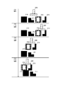
- FIG. 4 is a diagram schematically illustrating computer graphics generated by the computer 10 according to a time-series change.
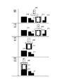
- FIG. 5 is a diagram schematically illustrating an image acquired by the computer 10 according to a time-series change.
- FIG. 1 is a diagram for explaining an outline of an operation verification system 1 according to a preferred embodiment of the present invention.
- the operation verification system 1 is a computer system that includes a computer 10 and executes operation verification of a machine tool.
- the operation verification system 1 includes other devices such as a photographing device for photographing a machine tool, various detection sensors for detecting the operation and posture of the machine tool, and an administrator terminal possessed by an administrator for managing the machine tool. And a sensor may be included.
- the computer 10 is a computer device connected to the above-described photographing device (not shown), various detection sensors, an administrator terminal, and the like via a public line network so as to be able to perform data communication.
- the computer 10 acquires data on the operation of the machine tool from various detection sensors.
- the predetermined time is a predetermined time or a time required for one or more steps.
- the computer 10 generates computer graphics (hereinafter, referred to as CG) virtually indicating that the machine tool operates for a predetermined time.
- the computer 10 converts not only the machine tool but also an object to be worked by the machine tool into CG.
- the computer 10 acquires an image of the machine tool at the same timing as the predetermined time for acquiring the data for operating the machine tool. This image is a moving image or a still image.
- the computer 10 compares the acquired image with the generated CG at a predetermined time.
- the computer 10 determines whether there is a difference between the CG and the image by comparing the CG and the image. If the difference exists, the computer 10 detects an abnormality of the machine tool.
- the computer 10 When the computer 10 detects an abnormality, the computer 10 estimates a part causing the abnormality of the machine tool as a cause of the abnormality. At this time, the computer 10 presumes that the part related to the part operating at the first time when the difference occurs is the cause of the abnormality.
- the portion is, for example, an arm.
- the part regarding the part is, for example, a position sensor provided on the arm.
- the computer 10 notifies the administrator terminal of the detection result. At this time, the computer 10 notifies the administrator of the estimated cause of the abnormality and the time at which the abnormality occurred as a detection result.
- the computer 10 obtains operation data indicating data on the operation of the machine tool (step S01).
- the computer 10 controls the operation and posture of the machine tool by using various detection sensors installed on the machine tool and various detection sensors installed at other places where the posture and operation of the machine tool can be detected. Data is acquired as operation data.
- the predetermined time is a time set in advance, a time required for one or more steps, a time required for a predetermined operation (moving, gripping, transporting, placing, etc.) set in advance.
- the computer 10 grasps the operation and posture of the machine tool.
- the computer 10 generates a CG that virtually indicates that the machine tool operates for a predetermined time from the acquired operation data (step S02).
- the computer 10 generates, in addition to the machine tool, an object to be worked by the machine tool as a CG.
- the computer 10 generates the CG based on a preset positional relationship between the machine tool and the object.
- the CG generated by the computer 10 is updated as needed in accordance with the acquired operation data.
- the computer 10 acquires an image to be shot at the same time as the predetermined time for generating the CG (step S03).
- the computer 10 acquires an image such as a moving image or a still image in which a photographing device has photographed a machine tool and an object.
- the computer 10 analyzes the acquired image and the generated CG, and compares the positional relationship between the machine tool and the object in each case (step S04). At this time, the computer 10 determines whether there is a difference between the CG and the image in the positional relationship between the machine tool and the object. For example, the computer 10 compares the positional relationship between the machine tool and the object from a start time to an end time in a predetermined time.
- the computer 10 determines that a difference has occurred as a result of the comparison, the computer 10 detects that an abnormality has occurred in the machine tool (step S05).
- the computer 10 estimates the cause of the detected abnormality (step S06).
- the computer 10 extracts, for example, the first time at which the difference occurs (the time at which the difference starts to occur between the CG and the image) from the comparison result, and operates the parts operating at this time and the parts operating at this time. It is presumed that the part related to the part to be caused is the cause of the abnormality.
- the computer 10 notifies the estimated abnormality (step S07).
- the computer 10 notifies the administrator terminal or the like of the fact that the abnormality has been detected and the estimated cause of the abnormality.
- the computer 10 notifies the administrator terminal that an abnormality has occurred in the machine tool and the parts and the like that have been estimated as the cause of the abnormality.
- the computer 10 may display the estimated abnormality on its own display unit. In this case, it is not always necessary to notify the administrator terminal.
- FIG. 2 is a diagram showing a system configuration of an operation verification system 1 according to a preferred embodiment of the present invention.
- an operation verification system 1 is a computer system that includes a computer 10 and executes operation verification of a machine tool.
- the operation verification system 1 may include other devices and sensors, such as an imaging device, various detection sensors, and an administrator terminal, which are not shown.
- the operation verification system 1 is communicably connected to other devices and sensors via a public line network or the like.
- the computer 10 includes a CPU (Central Processing Unit), a RAM (Random Access Memory), a ROM (Read Only Memory) as a control unit, and a communication unit such as the above-described photographing device, various detection sensors, and an administrator terminal.
- a device for enabling communication with other devices, sensors, and the like, for example, a Wi-Fi (Wireless-Fidelity) compatible device compliant with IEEE 802.11 is provided.
- the computer 10 includes, as a storage unit, a data storage unit such as a hard disk, a semiconductor memory, a recording medium, and a memory card.
- the computer 10 includes, as a processing unit, various devices that execute various processes.
- the control unit reads a predetermined program, and realizes the data acquisition module 20, the image acquisition module 21, and the notification module 22 in cooperation with the communication unit. Further, in the computer 10, the control unit reads a predetermined program, and in cooperation with the processing unit, the CG generation module 40, the analysis module 41, the positional relationship identification module 42, the comparison module 43, the determination module 44, the detection module 45, an extraction module 46, an operation part identification module 47, and an estimation module 48 are realized.
- FIG. 3 is a diagram illustrating a flowchart of the operation verification processing executed by the computer 10. The processing executed by each module described above will be described together with this processing.
- the data acquisition module 20 acquires data on the operation of the machine tool as operation data (step S10).
- the data acquisition module 20 outputs data relating to the posture and operation of the machine tool from a sensor (eg, a position sensor installed on an arm) installed at a predetermined position of the machine tool,
- the predetermined time is a time set in advance, a time required for the machine tool to execute one or a plurality of work steps, and a predetermined operation (moving, gripping, transporting, placing, etc.) Etc.).
- This predetermined time can be arbitrarily set by an administrator or the like.
- This sensor detects the posture or operation of the whole or a part of the machine tool.
- the CG generation module 40 generates a CG that virtually indicates the machine tool based on the acquired operation data (step S11).
- step S11 the CG generation module 40 generates a state in which the machine tool operates for a predetermined time as a CG.
- This CG is a three-dimensional one having a width, depth, and height.
- the CG generation module 40 generates, in addition to the machine tool, an object on which the machine tool operates as a CG. This object is generated as a CG based on a preset initial position.
- the CG generation module 40 generates a machine tool based on the operation data and an object based on a preset initial position as a CG.
- the CG generation module 40 generates the CG as a moving image and a still image.
- the CG generated by the CG generation module 40 is generated for a predetermined time (for example, when the operation of the machine tool starts and the operation is completed, or when one or more operation steps performed by the machine tool are completed). ) Will be saved.
- the CG generation module 40 deletes the stored CG when the detection module 45 detects that no abnormality has occurred in the processing described later.
- the CG generation module 40 updates the CG as needed based on the acquired operation data. In this case, the CG generation module 40 generates the CG generated first by changing the machine tool and the object on which the machine tool has operated in accordance with the operation data.
- the CG generation module 40 when the machine tool is an arm, a position sensor and a contact sensor are set on the arm, and the object is an assembly part, the CG generation module 40 generates a virtual arm based on the operation data. And generating a virtual assembly part based on the initial position of the assembly part. The CG generation module 40 generates one CG in which these virtual objects are put together. The CG generation module 40 reproduces the movement of the operation of the arm as a CG based on the operation data from the position sensor, and based on the operation data from the contact sensor, determines the position and the state of the assembly component gripped by the arm in the CG. Reproduce as. The CG generation module 40 continues this CG generation for a predetermined time.
- the image acquisition module 21 acquires an image photographed by the photographing device at the same time as the predetermined time during which the machine tool is generated as a CG (step S12).
- the photographing device photographs an image such as a moving image or a still image of the machine tool and the target object.
- the image capturing device captures an image at the same timing as the CG.
- the image acquisition module 21 acquires an image photographed by the photographing device.
- the CG generated by the CG generation module 40 and the image obtained by the image obtaining module 21 are synchronized in time.
- the image acquisition module 21 continues acquiring the image for a predetermined time.
- the image acquisition module 21 acquires this image as a moving image and a still image.
- the image acquired by the image acquisition module 21 is displayed for a predetermined time (for example, when the operation of the machine tool starts and the operation is completed, or when one or a plurality of operation steps executed by the machine tool is completed). ) Will be saved.
- the image acquisition module 21 deletes the stored image when the detection module 45 detects that no abnormality has occurred in the processing described later.
- One or more shooting devices In the case of one photographing device, an image is photographed from a place where the photographing device is installed. When there are a plurality of photographing devices, images are respectively photographed from a place where each photographing device is installed.
- the analysis module 41 analyzes the generated CG and the acquired image, respectively (step S13).
- the analysis module 41 performs image analysis by extracting each feature point or feature amount between the CG and the image.
- the analysis module 41 extracts, for example, a shape and a contour as feature points.
- the analysis module 41 extracts, for example, statistical numerical values such as an average, a variance, and a histogram of pixel values as the feature amount.
- the analysis module 41 continues this image analysis for a predetermined time.
- the positional relationship specifying module 42 specifies the positional relationship between the machine tool and the object in each of the CG and the image based on the result of the image analysis (step S14). In step S14, the positional relationship specifying module 42 specifies the positional relationship between the machine tool and the object in the CG and the image based on the extracted feature points or feature amounts. This positional relationship is, for example, specifying which position of the object the machine tool is holding, specifying which position of the object the machine tool is in contact with, and which position of the object is the machine tool. Is specified, and where the machine tool has set one object on another object. The positional relationship specifying module 42 continues to specify the machine tool and the object for a predetermined time.
- the comparison module 43 compares the CG and the image at a predetermined time (step S15).
- step S15 the comparison module 43 compares the positional relationship between the machine tool and the object in the CG and the positional relationship between the machine tool and the object in the image.
- the comparison module 43 compares the CG and the image at a time from the operation start time to the operation end time of the machine tool as the predetermined time.
- the operation start point is a timing at which the machine tool starts operation.
- the operation end point is a timing at which the machine tool completes a preset operation, or a timing at which a part or all of a work process preset in the machine tool ends.
- the comparison module 43 compares the still image and the moving image with each other.
- the comparison module 43 compares the CG generated as a still image with the image obtained as a still image, and also compares the CG generated as a moving image with the image obtained as a moving image.
- the computer 10 uses the result of the comparison between the two types for processing described later.
- the determination module 44 determines whether or not a difference has occurred in the positional relationship between the machine tool and the object between the CG and the image as a result of the comparison (step S16). In step S16, the determination module 44 determines, for example, a position at which the machine tool grips the object, a contact position between the machine tool and the object, an approach position between the machine tool and the object, There is a difference in the position where the utility machine places one object on another object. In step S16, when the determination module 44 determines that no difference has occurred (step S16 NO), the detection module 45 detects that no abnormality has occurred (step S17).
- the determination module 44 determines whether the operation of the machine tool has been completed (step S18). In step S18, the determination module 44 determines whether a predetermined time has elapsed, has completed a predetermined operation, or has completed a part or all of a predetermined work process in the CG and the image. Then, it is determined whether or not the operation has been completed. When the determination module 44 determines that the operation of the machine tool has been completed (step S18: YES), the detection module 45 detects that no abnormality has occurred, and ends this processing.
- step S18 when the determination module 44 determines that the operation of the machine tool has not been completed (step S18 NO), the data acquisition module 20 executes the processing of step S10 again.
- step S16 when the determination module 44 determines that a difference has occurred (step S16 YES), the detection module 45 detects that an abnormality has occurred (step S19).
- step S19 the detection module 45 determines, for example, a position at which the machine tool grips the object, a contact position between the machine tool and the object, an approach position between the machine tool and the object, and an object at the machine tool. The fact that the position where the object is placed on another object differs between the CG and the image is detected as abnormal.
- the extraction module 46 extracts the first time when the abnormality is detected (Step S20).
- step S20 the extraction module 46 extracts, from the time from when the comparison module 43 starts comparison to the time when the detection module 45 detects an abnormality, the first time when an abnormality is considered to have occurred. This is because the timing at which the detection module 45 detects an abnormality is merely a detection of a result indicating that an abnormality has occurred, and the actual abnormality has occurred at an earlier stage. For example, when the extraction module 46 detects an abnormality at a position where the machine tool grasps the target, the extraction module 46 determines a time during which the position of the machine tool is shifted at a stage before the machine tool grasps the object. Extract as the first time.
- the extraction module 46 detects an abnormality in the contact position between the machine tool and the object, the position of the machine tool is shifted at a stage before the machine tool comes into contact with the object. Is extracted as the first time. Further, for example, when the extraction module 46 detects an abnormality in the approach position between the machine tool and the object, the position of the machine tool at a stage before the machine tool approaches the object is shifted. Is extracted as the first time.
- the extraction module 46 for example, when the machine tool detects an abnormality at a position where one object is installed on another object, the machine tool installs one object on another object. The time at which the position of the machine tool at a stage earlier than this is shifted is extracted as the first time.
- the operation part specifying module 47 specifies a part that operates at the extracted first time (step S21).
- the operating part specifying module 47 specifies a part (for example, an arm or a claw) of the machine tool that operates at a timing corresponding to the extracted first time.
- the operating part specifying module 47 specifies a part operating at this time in either or both of the CG and the image.
- the operating part specifying module 47 specifies the part operating or operating at this time in the machine tool as the part operating at the extracted first time.
- the operation part specifying module 47 specifies the part installed in the specified part (step S22).
- the operation part specifying module 47 specifies the part installed in the part specified this time by referring to a table or the like in which each part of the machine tool and the part to be installed are stored in advance in association with each other. I do.
- the parts are, for example, a position sensor, a pressure sensor, and a direction sensor.
- the part identification module 47 identifies the position sensor associated with the arm. Identify the part installed in the part.
- the inference module 48 estimates the identified part as the cause of the abnormality (step S23). In step S23, the estimation module 48 estimates that the cause of the difference between the CG and the image is due to the part, and estimates that the part is the cause of the abnormality.
- the estimating module 48 may be configured to, when detecting that an abnormality has occurred in the above-described processing, estimate the part that causes the abnormality. For example, irrespective of the part operating at the extracted first time, a part installed in the part operating at the timing of detecting the abnormality may be estimated as the cause of the abnormality.
- the guessing module 48 has a configuration in which the operation part specifying module 47 specifies the part associated with this part by referring to the above-described table and the like, and guesses the specified part as the cause of the abnormality. There may be.
- the notification module 22 notifies the administrator terminal of the estimated part as the cause of the abnormality (step S24).
- step S24 the notification module 22 notifies the administrator terminal that the machine tool is not operating as expected due to an abnormality of a part installed in the machine tool.
- the administrator terminal notifies the administrator of the abnormality by displaying the notification on its own display unit. In this way, the notification module 22 notifies the administrator of the abnormality by displaying the notification on the administrator terminal. At this time, the notification module 22 also notifies the time when the abnormality has occurred.
- the notification module 22 may notify the administrator terminal that an abnormality has occurred, not limited to the estimated parts. Further, the notification module 22 may notify not only the guessed parts but also other abnormalities of the machine tool. In addition, the notification module 22 may be configured to notify the display unit of its own that an inferred part or abnormality has occurred. In this case, notification to the administrator terminal is not necessarily required.
- FIG. 4 is a diagram schematically illustrating a CG generated by the CG generation module 40 according to a time-series change.
- FIG. 5 is a diagram schematically illustrating an image acquired by the image acquisition module 21 according to a time-series change.
- the CG generation module 40 reproduces an arm 200 as a machine tool and an assembled part 210-213 as an object as a CG as a process in step S11 based on the operation data acquired in the process in step S10.
- I have.
- CG1 is the CG at the start of the operation of the arm 200.
- CG2 is the CG at the time when the time has elapsed by T1 from the operation start time.
- CG3 is the CG at the point in time when T2 has elapsed since CG2.
- CG4 is the CG at the point in time when T3 has elapsed since CG3.
- FIG. 5 shows an image acquired by the image acquisition module 21 in the process of step S12.
- the image 1 is an image at the time when the operation of the arm 200 is started.
- Image 2 is an image at the time when the time has elapsed by T1 from the operation start time.
- the image 3 is an image at the time when a time T2 has elapsed from the image 2.
- the image 4 is an image at the time when a time T3 has elapsed from the image 3.
- the analysis module 41 performs an image analysis on the CG and the image by the process of step S13.
- the positional relationship specifying module 42 specifies the positional relationship between the arm 200 and the target object 210-213 in each of the CG and the image based on the result of the image analysis on the CG and the image by the processing in step S14.
- the comparison module 43 compares the CG and the image in the time from the start time to the time after the elapse of T3 minutes by the processing of step S15. At this time, the comparison module 43 compares the image 1 with CG1 (time at the start time), compares the image 2 with CG2 (time elapsed by T1 minutes from the start time), and compares the image 3 with CG3 (time at T1 minute). The image 4 and CG4 are compared (time T3 minutes have elapsed since the time T2 elapsed). The comparison module 43 compares the positional relationship between the arm 200 and the objects 210 to 213 in each image and CG.
- the determination module 44 determines whether or not a difference has occurred between the CG and the image by the process of step S16. Here, the determination module 44 determines that a difference has occurred since a difference has occurred between the image 4 and the CG 4. When there is no difference between the CG and the image, the determination module 44 and the detection module 45 execute the processing of steps S17 to S18.
- the judgment module 44 judges that the arm 200 is grasping only the object 212 in the image 2 while the arm 200 is grasping the object 212 and 213 in CG2 at the time point when T1 has elapsed. . Further, the judgment module 44 determines that the arm 200 is grasping only the object 212 in the image 3 while the arm 200 is grasping the object 212 and 213 in the CG3 when the time T2 has elapsed. to decide. In addition, the judgment module 44 determines that the arm 200 has grasped the objects 212 and 213 in the CG4 at the time point when the time T3 has elapsed, while the objects 212 and 213 are placed on the object 210. In image 4, it is determined that the arm 200 places the object 212 on the object 210.
- the detection module 45 detects an abnormality at the time from the lapse of T1 minutes, which is the time when the difference occurs, to the lapse of T3 minutes. Is detected.
- the extraction module 46 extracts the first time when the abnormality is detected by the processing in step S20.
- the extraction module 46 extracts a point in time at which T1 has elapsed, which is the first time at which a difference has occurred, as the first time at which an abnormality is detected.
- the operation part specifying module 47 specifies the arm 200 as the part that operates when the time T1 has elapsed by the process of step S21.
- the operation part specifying module 47 specifies a position sensor previously associated with the arm 200 as a part installed on the arm 200 by the process of step S22.
- the estimation module 48 estimates the identified position sensor as the cause of the abnormality by the processing in step S23.
- the notification module 22 gives a notification that the position sensor is abnormal due to the processing in step S24, and as a result, the arm 200 is not operating as expected.
- the means and functions described above are implemented when a computer (including a CPU, an information processing device, and various terminals) reads and executes a predetermined program.
- the program is provided, for example, in the form of being provided from a computer via a network (SaaS: Software as a Service).
- the program is provided in a form recorded on a computer-readable recording medium such as a flexible disk, a CD (eg, a CD-ROM), and a DVD (eg, a DVD-ROM, a DVD-RAM).
- the computer reads the program from the recording medium, transfers the program to an internal recording device or an external recording device, records the program, and executes the program.
- the program may be recorded in a recording device (recording medium) such as a magnetic disk, an optical disk, or a magneto-optical disk in advance, and may be provided from the recording device to a computer via a communication line.
Landscapes
- Engineering & Computer Science (AREA)
- Physics & Mathematics (AREA)
- General Physics & Mathematics (AREA)
- Theoretical Computer Science (AREA)
- Human Computer Interaction (AREA)
- Manufacturing & Machinery (AREA)
- Automation & Control Theory (AREA)
- Computer Vision & Pattern Recognition (AREA)
- Quality & Reliability (AREA)
- Computer Graphics (AREA)
- Mechanical Engineering (AREA)
- Robotics (AREA)
- Computer Hardware Design (AREA)
- General Engineering & Computer Science (AREA)
- Software Systems (AREA)
- General Factory Administration (AREA)
- Image Analysis (AREA)
- Numerical Control (AREA)
- Testing And Monitoring For Control Systems (AREA)
Abstract
【課題】工作用機械の動作をより正確に把握することが容易なコンピュータシステム、動作検証方法及びプログラムを提供することを目的とする。 【解決手段】コンピュータシステムは、工作用機械が所定時間動作する際に、動作したデータを取得し、取得した前記データから前記工作用機械が所定時間動作することを仮想的に示すコンピュータグラフィックスを生成し、前記工作用機械を、前記所定時間撮影した画像を取得し、前記画像と、前記コンピュータグラフィックスとを前記所定時間において比較する。コンピュータシステムは、比較した結果、異常を検知した場合、異常を通知する。
Description
本発明は、工作用機械の動作検証を行うコンピュータシステム、動作検証方法及びプログラムに関する。
近年、工業分野において、製品の製造工程を、コンピュータグラフィックスで再現するデジタルツインという技術が知られている。このような技術において、工作用機械の姿勢や動作をセンサ情報から取得し、この取得したセンサ情報に基づいて工作用機械の姿勢や動作をコンピュータグラフィックスにより再現している。
このようなデジタルツインに類似する技術として、作業者が作業する作業空間の3次元データを取得し、この3次元データと、作業マニュアルに基づいた作業手順とを比較することにより、作業工程の終了条件を満たしたか否かを判断する技術が開示されている(特許文献1参照)。
しかしながら、特許文献1の構成では、3次元データに必要なデータをセンサから取得するが、このセンサが不具合を起こしている場合、正確な3次元データを生成することができないため、3次元データが正確な動作を反映していないおそれがあった。
本発明は、工作用機械の動作をより正確に把握することが容易なコンピュータシステム、動作検証方法及びプログラムを提供することを目的とする。
本発明では、以下のような解決手段を提供する。
本発明は、工作用機械が所定時間動作する際に、動作したデータを取得するデータ取得手段と、
取得した前記データから前記工作用機械が所定時間動作することを仮想的に示すコンピュータグラフィックスを生成するCG生成手段と、
前記工作用機械を、前記所定時間撮影した画像を取得するカメラ画像取得手段と、
前記画像と、前記コンピュータグラフィックスとを前記所定時間において比較する比較手段と、
を備えることを特徴とするコンピュータシステムを提供する。
取得した前記データから前記工作用機械が所定時間動作することを仮想的に示すコンピュータグラフィックスを生成するCG生成手段と、
前記工作用機械を、前記所定時間撮影した画像を取得するカメラ画像取得手段と、
前記画像と、前記コンピュータグラフィックスとを前記所定時間において比較する比較手段と、
を備えることを特徴とするコンピュータシステムを提供する。
本発明によれば、コンピュータシステムは、工作用機械が所定時間動作する際に、動作したデータを取得し、取得した前記データから前記工作用機械が所定時間動作することを仮想的に示すコンピュータグラフィックスを生成し、前記工作用機械を、前記所定時間撮影した画像を取得し、前記画像と、前記コンピュータグラフィックスとを前記所定時間において比較する。
本発明は、コンピュータシステムのカテゴリであるが、方法及びプログラム等の他のカテゴリにおいても、そのカテゴリに応じた同様の作用・効果を発揮する。
本発明によれば、工作用機械の動作をより正確に把握することが容易なコンピュータシステム、動作検証方法及びプログラムを提供することが可能となる。
以下、本発明を実施するための最良の形態について図を参照しながら説明する。なお、これはあくまでも一例であって、本発明の技術的範囲はこれに限られるものではない。
[動作検証システム1の概要]
本発明の好適な実施形態の概要について、図1に基づいて説明する。図1は、本発明の好適な実施形態である動作検証システム1の概要を説明するための図である。動作検証システム1は、コンピュータ10から構成され、工作用機械の動作検証を実行するコンピュータシステムである。
本発明の好適な実施形態の概要について、図1に基づいて説明する。図1は、本発明の好適な実施形態である動作検証システム1の概要を説明するための図である。動作検証システム1は、コンピュータ10から構成され、工作用機械の動作検証を実行するコンピュータシステムである。
なお、動作検証システム1は、工作用機械を撮影する撮影機器、工作用機械の動作や姿勢を検知する各種検知センサ、工作用機械を管理する管理者が所持する管理者端末等の他の機器やセンサ等が含まれていてもよい。
コンピュータ10は、図示してない上述した撮影機器、各種検知センサ、管理者端末等と公衆回線網等を介してデータ通信可能に接続されたコンピュータ装置である。
コンピュータ10は、工作用機械が所定時間動作する際、この工作用機械が動作したデータを各種検知センサから取得する。所定時間としては、予め決められた時間や、一又は複数の工程に必要な時間である。コンピュータ10は、このデータから、この工作用機械が所定時間動作することを仮想的に示すコンピュータグラフィックス(以下、CGと称す)を生成する。このとき、コンピュータ10は、工作用機械のみならず、この工作用機械が作業対象とする対象物も併せてCG化する。加えて、コンピュータ10は、工作用機械が動作するデータを取得する所定時間と同じタイミングで、この工作用機械を撮影した画像を取得する。この画像は、動画又は静止画である。コンピュータ10は、取得した画像と、生成したCGとを所定時間において比較する。コンピュータ10は、CGと画像とを比較することにより、これらの間に差異が存在するかを判断し、差異が存在する場合、工作用機械の異常を検知する。
コンピュータ10は、異常を検知した場合、この工作用機械の異常の原因となるパーツを異常の原因として推測する。このとき、コンピュータ10は、差異が発生した最初の時間に動作している部分に関するパーツを異常の原因と推測する。部分とは、例えば、アームである。部分に関するパーツとは、例えば、アームに設けられた位置センサである。
コンピュータ10は、この検知結果を、管理者端末に通知する。このとき、コンピュータ10は、推測した異常の原因とその発生した時間とを管理者に検知結果として通知する。
動作検証システム1が実行する処理の概要について説明する。
初めに、コンピュータ10は、工作用機械が所定時間動作する際、この工作用機械が動作したデータを示す動作データを取得する(ステップS01)。コンピュータ10は、この工作用機械に設置された各種検知センサや、この工作用機械の姿勢や動作等を検知可能なその他の場所に設置された各種検知センサにより、工作用機械の動作や姿勢に関するデータを、動作データとして取得する。所定時間とは、予め設定された時間や、1又は複数の工程に必要な時間や、予め設定された所定の動作(移動、握持、運搬、載置等)に必要な時間等である。コンピュータ10は、この動作データを取得することにより、工作用機械の動作や姿勢を把握する。
コンピュータ10は、取得した動作データから、工作用機械が所定時間動作することを仮想的に示すCGを生成する(ステップS02)。コンピュータ10は、工作用機械に加え、この工作用機械が作業対象とする対象物も併せてCGとして生成する。このとき、コンピュータ10は、工作用機械と対象物との初期位置を、予め設定された位置関係に基づいてこのCGを生成する。コンピュータ10が生成するCGは、取得する動作データに併せて随時更新される。
コンピュータ10は、CGを生成する所定時間と同一時間に撮影する画像を取得する(ステップS03)。コンピュータ10は、撮影機器が工作用機器及び対象物を撮影した動画や静止画等の画像を取得する。
コンピュータ10は、取得した画像と、生成したCGとを画像解析し、其々における工作用機械と対象物との位置関係を比較する(ステップS04)。このとき、コンピュータ10は、CGと画像との間で、工作用機械と対象物との位置関係に差異が存在しているか否かを判断する。例えば、コンピュータ10は、所定時間における開始時点から終了時点までの工作用機械と対象物との位置関係を比較する。
コンピュータ10は、比較した結果、差異が発生していると判断した場合、工作用機械に何らかの異常が発生していることを検知する(ステップS05)。
コンピュータ10は、検知した異常の原因を推測する(ステップS06)。コンピュータ10は、例えば、差異が発生した最初の時間(CGと画像とで差異が発生し始めた時間)を、比較した結果から抽出し、この時間において動作しているパーツや、この時間において動作する部分に関するパーツが異常の原因であるものと推測する。
コンピュータ10は、推測した異常を通知する(ステップS07)。コンピュータ10は、異常を検知した事実や、推測した異常の原因を管理者端末等に通知する。コンピュータ10は、工作用機械に異常が発生している旨、異常の原因として推測したパーツ等を管理者端末に通知する。
なお、コンピュータ10は、推測した異常を自身の表示部に表示してもよい。この場合、管理者端末に必ずしも通知する必要はない。
以上が、動作検証システム1の概要である。
[動作検証システム1のシステム構成]
図2に基づいて、本発明の好適な実施形態である動作検証システム1のシステム構成について説明する。図2は、本発明の好適な実施形態である動作検証システム1のシステム構成を示す図である。図2において、動作検証システム1は、コンピュータ10から構成され、工作用機械の動作検証を実行するコンピュータシステムである。
図2に基づいて、本発明の好適な実施形態である動作検証システム1のシステム構成について説明する。図2は、本発明の好適な実施形態である動作検証システム1のシステム構成を示す図である。図2において、動作検証システム1は、コンピュータ10から構成され、工作用機械の動作検証を実行するコンピュータシステムである。
なお、動作検証システム1は、上述した通り、図示していない撮影機器、各種検知センサ、管理者端末等の他の機器やセンサ等が含まれていてもよい。動作検証システム1は、他の機器やセンサ等と公衆回線網等を介してデータ通信可能に接続される。
コンピュータ10は、制御部として、CPU(Central Processing Unit)、RAM(Random Access Memory)、ROM(Read Only Memory)等を備え、通信部として、上述した撮影機器、各種検知センサ、管理者端末等の他の機器やセンサ等と通信可能にするためのデバイス、例えば、IEEE802.11に準拠したWi―Fi(Wireless―Fidelity)対応デバイス等を備える。また、コンピュータ10は、記憶部として、ハードディスクや半導体メモリ、記録媒体、メモリカード等によるデータのストレージ部を備える。また、コンピュータ10は、処理部として、各種処理を実行する各種デバイス等を備える。
コンピュータ10において、制御部が所定のプログラムを読み込むことにより、通信部と協働して、データ取得モジュール20、画像取得モジュール21、通知モジュール22を実現する。また、コンピュータ10において、制御部が所定のプログラムを読み込むことにより、処理部と協働して、CG生成モジュール40、解析モジュール41、位置関係特定モジュール42、比較モジュール43、判断モジュール44、検知モジュール45、抽出モジュール46、動作部分特定モジュール47、推測モジュール48を実現する。
[動作検証処理]
図3に基づいて、動作検証システム1が実行する動作検証処理について説明する。図3は、コンピュータ10が実行する動作検証処理のフローチャートを示す図である。上述した各モジュール実行する処理について、本処理に併せて説明する。
図3に基づいて、動作検証システム1が実行する動作検証処理について説明する。図3は、コンピュータ10が実行する動作検証処理のフローチャートを示す図である。上述した各モジュール実行する処理について、本処理に併せて説明する。
データ取得モジュール20は、工作用機械が所定時間動作する際に、この工作用機械が動作したデータを、動作データとして取得する(ステップS10)。ステップS10において、データ取得モジュール20は、工作用機械の所定の位置に設置されたセンサ(例えば、アームに設置された位置センサ)から、この工作用機械の姿勢や動作等に関するデータを、動作データとして取得する。所定時間とは、予め設定された時間や、この工作用機械が1又は複数の作業工程を実行するために必要な時間や、予め設定された所定の動作(移動、握持、運搬、載置等)に必要な時間等である。この所定時間は、管理者等が任意に設定可能である。このセンサは、工作用機械の全体又は一部の姿勢や動作を検知するものである。
CG生成モジュール40は、取得した動作データに基づいて、この工作用機械を仮想的に示すCGを生成する(ステップS11)。ステップS11において、CG生成モジュール40は、工作用機械が所定時間動作する状態をCGとして生成する。このCGは、幅・奥行・高さを有する3次元のものである。CG生成モジュール40は、工作用機械に加えて、この工作用機械が動作する対象となる対象物も併せてCGとして生成する。この対象物は、予め設定された初期位置に基づいてCGとして生成する。CG生成モジュール40は、動作データに基づいた工作用機械と、予め設定された初期位置に基づいた対象物とをCGとして生成する。CG生成モジュール40は、動画及び静止画として、このCGを生成する。CG生成モジュール40が生成したCGは、所定時間(例えば、この工作用機械が動作を開始し、その動作が完了する時点や、この工作用機械が実行する一又は複数の作業工程が完了する時点)保存される。CG生成モジュール40は、後述する処理において、検知モジュール45が、異常が発生していないことを検知した場合、この保存したCGを削除する。
CG生成モジュール40は、取得した動作データに基づいて、随時CGを更新する。この場合、CG生成モジュール40は、最初に生成したCGのうち、工作用機械及びこの工作用機械が動作した対象物を、動作データに併せて変化させたものを生成する。
例えば、工作用機械がアームであり、このアームに位置センサ及び接触センサが設定され、対象物が組立て部品である場合、CG生成モジュール40は、動作データに基づいて、仮想的なアームを生成し、組立て部品の初期位置に基づいて、仮想的な組立て部品を生成する。CG生成モジュール40は、これらの仮想物をまとめた一のCGを生成する。CG生成モジュール40は、位置センサからの動作データに基づいて、アームの動作の動きをCGとして再現するとともに、この接触センサからの動作データに基づいて、アームが掴む組立て部品の位置や状態をCGとして再現する。CG生成モジュール40は、このCGの生成を、所定時間続行する。
画像取得モジュール21は、撮影機器が、工作用機械をCGとして生成する所定時間と同一時間に撮影した画像を取得する(ステップS12)。ステップS12において、撮影機器は、工作用機械及び対象物の動画や静止画等の画像を撮影する。このとき、撮影機器は、CGと同一のタイミングで画像を撮影する。画像取得モジュール21は、この撮影機器が撮影した画像を取得する。このとき、CG生成モジュール40が生成するCGと、画像取得モジュール21が取得する画像とは、その時間が同期されたものとなる。画像取得モジュール21は、この画像の取得を、所定時間続行する。画像取得モジュール21は、動画及び静止画として、この画像を取得する。画像取得モジュール21が取得した画像は、所定時間(例えば、この工作用機械が動作を開始し、その動作が完了する時点や、この工作用機械が実行する一又は複数の作業工程が完了する時点)保存される。画像取得モジュール21は、後述する処理において、検知モジュール45が、異常が発生していないことを検知した場合、この保存した画像を削除する。
撮影機器は、一又は複数である。一の撮影機器の場合、この撮影機器が設置された場所から、画像を撮影する。複数の撮影機器である場合、各撮影機器が設置された場所から、其々画像を撮影する。
解析モジュール41は、生成したCGと、取得した画像とを其々画像解析する(ステップS13)。ステップS13において、解析モジュール41は、CGと画像との其々の特徴点又は特徴量を抽出することにより、画像解析を実行する。解析モジュール41は、特徴点として、例えば、形状、輪郭を抽出する。解析モジュール41は、特徴量として、例えば、画素値の平均、分散、ヒストグラム等の統計的な数値を抽出する。解析モジュール41は、この画像解析を、所定時間続行する。
位置関係特定モジュール42は、画像解析の結果に基づいて、CGと画像との其々における工作用機械と対象物との位置関係を特定する(ステップS14)。ステップS14において、位置関係特定モジュール42は、抽出した特徴点又は特徴量に基づいて、CGと画像とにおける工作用機械と対象物との位置関係を特定する。この位置関係とは、例えば、工作用機械が対象物のどの位置を掴んでいるかの特定、工作用機械が対象物のどの位置と接触しているかの特定、工作用機械が対象物のどの位置に接近しているかの特定、工作用機械が一の対象物を他の対象物のどの位置に設置したかの特定である。位置関係特定モジュール42は、工作用機械と対象物との特定を、所定時間続行する。
比較モジュール43は、CGと画像とを、所定時間において比較する(ステップS15)。ステップS15において、比較モジュール43は、CGにおける工作用機械と対象物との位置関係と、画像における工作用機械と対象物との位置関係とを比較する。比較モジュール43は、所定時間として、工作用機械の動作開始時点から動作終了時点までの時間において、CGと画像とを比較する。動作開始時点とは、工作用機械が動作を開始したタイミングである。動作終了時点とは、工作用機械が予め設定された動作を終了したタイミングや、工作用機械に予め設定された作業工程の一部又は全部が終了したタイミングである。比較モジュール43は、CGと画像とを比較する際、静止画と動画の2種類で其々比較する。すなわち、比較モジュール43は、静止画として生成したCGと、静止画として取得した画像とを比較するとともに、動画として生成したCGと、動画として取得した画像とを比較する。コンピュータ10は、これら2種類を比較した結果を、後述する処理に利用する。
判断モジュール44は、比較した結果、CGと画像とで、工作用機械と対象物との位置関係に差異が発生しているか否かを判断する(ステップS16)。ステップS16において、判断モジュール44は、位置関係の差異として、例えば、工作用機械が対象物を掴む位置、工作用機械と対象物との接触位置、工作用機械と対象物との接近位置、工作用機械が一の対象物を他の対象物に設置した位置における相違が挙げられる。ステップS16において、判断モジュール44は、差異が発生していないと判断した場合(ステップS16 NO)、検知モジュール45は、異常が発生していないことを検知する(ステップS17)。
判断モジュール44は、工作用機械が動作終了したか否かを判断する(ステップS18)。ステップS18において、判断モジュール44は、CGと画像とにおいて、予め設定された所定時間が経過したか、予め設定された動作を終了したか、予め設定された作業工程の一部又は全部を終了したかに基づいて、動作終了したか否かを判断する。判断モジュール44は、工作用機械が動作終了したと判断した場合(ステップS18 YES)、検知モジュール45は、異常が発生していないことを検知し、本処理を終了する。
一方、ステップS18において、判断モジュール44は、工作用機械が動作終了していないと判断した場合(ステップS18 NO)、データ取得モジュール20は、上述したステップS10の処理を再度実行する。
ステップS16において、判断モジュール44は、差異が発生していると判断した場合(ステップS16 YES)、検知モジュール45は、異常が発生していることを検知する(ステップS19)。ステップS19において、検知モジュール45は、例えば、工作用機械が対象物を掴む位置、工作用機械と対象物との接触位置、工作用機械と対象物との接近位置、工作用機械が一の対象物を他の対象物に設置した位置がCGと画像とで異なっていることを異常として検知する。
抽出モジュール46は、異常を検知した最初の時間を抽出する(ステップS20)。ステップS20において、抽出モジュール46は、比較モジュール43が比較を開始した時点から、検知モジュール45が異常を検知した時点までの時間のうち、異常が発生したと考えられる最初の時間を抽出する。これは、検知モジュール45が異常を検知したタイミングは、あくまでも異常が発生したという結果を検知するものに過ぎず、実際の異常は、それ以前の段階で発生しているためである。抽出モジュール46は、例えば、工作用機械が対象物を掴む位置に異常を検知した場合、この工作用機械が対象物を掴むよりも前の段階での工作用機械の位置がずれている時間を最初の時間として抽出する。また、抽出モジュール46は、例えば、工作用機械と対象物との接触位置に異常を検知した場合、この工作用機械が対象物と接触するよりも前の段階での工作用機械の位置がずれている時間を最初の時間として抽出する。また、抽出モジュール46は、例えば、工作用機械と対象物との接近位置に異常を検知した場合、この工作用機械が対象物に接近するよりも前の段階での工作用機械の位置がずれている時間を最初の時間として抽出する。また、抽出モジュール46は、例えば、工作用機械が一の対象物を他の対象物に設置した位置に異常を検知した場合、この工作用機械が一の対象物を他の対象物に設置するよりも前の段階での工作用機械の位置がずれている時間を最初の時間として抽出する。
動作部分特定モジュール47は、抽出した最初の時間に動作する部分を特定する(ステップS21)。ステップS21において、動作部分特定モジュール47は、抽出した最初の時間に該当するタイミングで動作する工作用機械の部分(例えば、アーム、爪)を特定する。動作部分特定モジュール47は、CG又は画像の何れか又は双方において、この時間に動作する部分を特定する。動作部分特定モジュール47は、工作用機械においてこの時間に動作する又は動作した部分を、抽出した最初の時間に動作する部分として特定する。
動作部分特定モジュール47は、この特定した部分に設置されたパーツを特定する(ステップS22)。ステップS22において、動作部分特定モジュール47は、予め工作用機械の各部分と、設置するパーツとを対応付けて記憶させたテーブル等を参照することにより、今回特定した部分に設置されたパーツを特定する。このパーツとは、例えば、位置センサ、圧力センサ、方位センサである。部分特定モジュール47は、例えば、上述したテーブルにおいて、アームと位置センサとが対応付けられている場合、今回特定した部分がアームであるとき、このアームに対応付けられた位置センサを、この特定した部分に設置されたパーツとして特定する。
推測モジュール48は、特定したパーツを、異常の原因として推測する(ステップS23)。ステップS23において、推測モジュール48は、CGと画像とで差異が発生している原因が、このパーツによるものであると推測し、このパーツが異常の原因であると推測する。
推測モジュール48は、上述した処理において、異常が発生していることを検知した際、この異常の原因となるパーツを推測する構成であってもよい。例えば、抽出した最初の時間に動作する部分に関わらず、異常を検知したタイミングで動作する部分に設置されたパーツを、異常の原因として推測してもよい。これは、推測モジュール48は、動作部分特定モジュール47が、この部分に対応付けられたパーツを上述したテーブル等を参照することにより特定し、この特定したパーツを、異常の原因として推測する構成であってもよい。
通知モジュール22は、推測したパーツを、異常の原因として管理者端末に通知する(ステップS24)。ステップS24において、通知モジュール22は、工作用機械が、この工作用機械に設置されたパーツの異常により、想定通りの動作をしていないことを管理者端末に通知する。管理者端末は、この通知を自身の表示部に表示することにより、管理者に異常を通知する。このようにすることにより、通知モジュール22は、管理者端末に通知を表示させることにより、管理者に異常を通知する。このとき、通知モジュール22は、異常が発生した時間も併せて通知する。
なお、通知モジュール22は、推測したパーツに限らず、異常が発生したことを管理者端末に通知してもよい。また、通知モジュール22は、推測したパーツだけでなく、それ以外にも工作用機械の異常を通知してもよい。また、通知モジュール22は、自身の表示部に推測したパーツや異常が発生していることを通知する構成であってもよい。この場合、管理者端末へ通知は必ずしも必要としない。
以上が、動作検証処理である。
ここで、図4及び図5に基づいて、上述した動作検証処理について説明する。図4は、CG生成モジュール40が生成するCGを時系列の変化に従って模式的に示す図である。図5は、画像取得モジュール21が取得する画像を時系列の変化に従って模式的に示す図である。
図4において、CG生成モジュール40は、ステップS10の処理により取得した動作データに基づいて、ステップS11の処理として、工作用機械としてアーム200、対象物として組立て部品210-213をCGとして再現している。CG1は、アーム200の動作開始時点におけるCGである。CG2は、動作開始時点からT1分だけ時間が経過した時点におけるCGである。CG3は、CG2からT2分だけ時間が経過した時点におけるCGである。CG4は、CG3からT3分だけ時間が経過した時点におけるCGである。
図5において、画像取得モジュール21が、ステップS12の処理により取得する画像を示している。画像1は、アーム200の動作開始時点における画像である。画像2は、動作開始時点からT1分だけ時間が経過した時点における画像である。画像3は、画像2からT2分だけ時間が経過した時点における画像である。画像4は、画像3からT3分だけ時間が経過した時点における画像である。
図4及び図5において、時間T1、T2及びT3はCGと画像とで同じ時間である。
解析モジュール41は、ステップS13の処理によりCG及び画像に対して画像解析を実行する。位置関係特定モジュール42は、ステップS14の処理により、CG及び画像に対する画像解析の結果に基づいて、CG及び画像の其々におけるアーム200と対象物210-213との位置関係を特定する。
比較モジュール43は、ステップS15の処理により、この開始時点からT3分経過後までの時間においてCGと画像とを比較する。このとき、比較モジュール43は、画像1とCG1と(開始時点の時間)を比較し、画像2とCG2と(開始時点からT1分経過した時間)を比較し、画像3とCG3と(T1分経過時点からT2分経過した時間)を比較し、画像4とCG4と(T2分経過時点からT3分経過した時間)を比較する。比較モジュール43は、各画像とCGとにおいて、アーム200と、対象物210-213との位置関係を比較する。
判断モジュール44は、ステップS16の処理により、CGと画像とで差異が発生しているか否かを判断する。ここで、判断モジュール44は、画像4とCG4とで差異が発生していることから、差異が発生していると判断する。なお、判断モジュール44は、CGと画像とで差異が発生していない場合、判断モジュール44及び検知モジュール45は、ステップS17-S18の処理を実行する。
判断モジュール44は、T1分経過時点で、CG2では、アーム200が対象物212及び213を掴んでいるのに対して、画像2では、アーム200が対象物212のみを掴んでいることを判断する。また、判断モジュール44は、T2分経過時点で、CG3では、アーム200が対象物212及び213を掴んでいるのに対して、画像3では、アーム200が対象物212のみを掴んでいることを判断する。また、判断モジュール44は、T3分経過時点で、CG4では、アーム200が対象物212及び213を掴んでおり、この対象物212及び213を、対象物210に載置しているのに対して、画像4では、アーム200が対象物212を、対象物210に載置していることを判断する。
検知モジュール45は、ステップS19の処理により、CGと画像とで差異が発生していることから、この差異が発生している時間であるT1分経過から、T3分経過までの時点で異常が発生していることを検知する。
抽出モジュール46は、ステップS20の処理により、異常を検知した最初の時間を抽出する。抽出モジュール46は、差異が発生している最初の時間であるT1分経過時点を、異常を検知した最初の時間として抽出する。
動作部分特定モジュール47は、ステップS21の処理により、このT1分経過時点において動作する部分として、アーム200を特定する。
動作部分特定モジュール47は、ステップS22の処理により、このアーム200に設置されたパーツとして、このアーム200に予め対応付けられた位置センサを特定する。
推測モジュール48は、ステップS23の処理により、この特定した位置センサを、異常の原因として推測する。
通知モジュール22は、ステップS24の処理により、この位置センサに異常が発生しており、その結果、アーム200が想定通りの動作をしていない旨の通知を行う。
以上が、図4及び図5に基づいた動作検証処理である。
上述した手段、機能は、コンピュータ(CPU、情報処理装置、各種端末を含む)が、所定のプログラムを読み込んで、実行することによって実現される。プログラムは、例えば、コンピュータからネットワーク経由で提供される(SaaS:ソフトウェア・アズ・ア・サービス)形態で提供される。また、プログラムは、例えば、フレキシブルディスク、CD(CD-ROMなど)、DVD(DVD-ROM、DVD-RAMなど)等のコンピュータ読取可能な記録媒体に記録された形態で提供される。この場合、コンピュータはその記録媒体からプログラムを読み取って内部記録装置又は外部記録装置に転送し記録して実行する。また、そのプログラムを、例えば、磁気ディスク、光ディスク、光磁気ディスク等の記録装置(記録媒体)に予め記録しておき、その記録装置から通信回線を介してコンピュータに提供するようにしてもよい。
以上、本発明の実施形態について説明したが、本発明は上述したこれらの実施形態に限るものではない。また、本発明の実施形態に記載された効果は、本発明から生じる最も好適な効果を列挙したに過ぎず、本発明による効果は、本発明の実施形態に記載されたものに限定されるものではない。
1 動作検証システム、10 コンピュータ
Claims (6)
- 工作用機械が所定時間動作する際に、動作したデータを取得するデータ取得手段と、
取得した前記データから前記工作用機械が所定時間動作することを仮想的に示すコンピュータグラフィックスを生成するCG生成手段と、
前記工作用機械を、前記所定時間撮影した画像を取得するカメラ画像取得手段と、
前記画像と、前記コンピュータグラフィックスとを前記所定時間において比較する比較手段と、
を備えることを特徴とするコンピュータシステム。 - 比較した結果、前記工作用機械が異なる動作をしている場合、当該工作用機械の異常を検知する検知手段と、
検知した前記異常を通知する通知手段と、
をさらに備えることを特徴とする請求項1に記載のコンピュータシステム。 - 前記異常を検知した場合、前記工作用機械の異常の原因となるパーツを推測する推測手段と、
をさらに備え、
前記通知手段は、推測した前記パーツを通知する、
ことを特徴とする請求項2に記載のコンピュータシステム。 - 前記異常を検知した場合、前記異なる動作が発生した最初の時間を抽出する抽出手段と、
をさらに備え、
前記推測手段は、抽出した前記最初の時間に動作する部分に関するパーツを、異常の原因と推測する、
ことを特徴とする請求項3に記載のコンピュータシステム。 - コンピュータシステムが実行する動作検証方法であって、
工作用機械が所定時間動作する際に、動作したデータを取得するステップと、
取得した前記データから前記工作用機械が所定時間動作することを仮想的に示すコンピュータグラフィックスを生成するステップと、
前記工作用機械を、前記所定時間撮影した画像を取得するステップと、
前記画像と、前記コンピュータグラフィックスとを前記所定時間において比較するステップと、
を備えることを特徴とする動作検証方法。 - コンピュータシステムに、
工作用機械が所定時間動作する際に、動作したデータを取得するステップ、
取得した前記データから前記工作用機械が所定時間動作することを仮想的に示すコンピュータグラフィックスを生成するステップ、
前記工作用機械を、前記所定時間撮影した画像を取得するステップ、
前記画像と、前記コンピュータグラフィックスとを前記所定時間において比較するステップ、
を実行させるためのコンピュータ読み取り可能なプログラム。
Priority Applications (4)
| Application Number | Priority Date | Filing Date | Title |
|---|---|---|---|
| JP2020539904A JP6875056B2 (ja) | 2018-08-28 | 2018-08-28 | コンピュータシステム、動作検証方法及びプログラム |
| CN201880098487.8A CN112805746A (zh) | 2018-08-28 | 2018-08-28 | 计算机系统、动作验证方法及程序 |
| US17/271,758 US11188053B2 (en) | 2018-08-28 | 2018-08-28 | Computer system, operation verification method, and program |
| PCT/JP2018/031784 WO2020044440A1 (ja) | 2018-08-28 | 2018-08-28 | コンピュータシステム、動作検証方法及びプログラム |
Applications Claiming Priority (1)
| Application Number | Priority Date | Filing Date | Title |
|---|---|---|---|
| PCT/JP2018/031784 WO2020044440A1 (ja) | 2018-08-28 | 2018-08-28 | コンピュータシステム、動作検証方法及びプログラム |
Publications (1)
| Publication Number | Publication Date |
|---|---|
| WO2020044440A1 true WO2020044440A1 (ja) | 2020-03-05 |
Family
ID=69643398
Family Applications (1)
| Application Number | Title | Priority Date | Filing Date |
|---|---|---|---|
| PCT/JP2018/031784 Ceased WO2020044440A1 (ja) | 2018-08-28 | 2018-08-28 | コンピュータシステム、動作検証方法及びプログラム |
Country Status (4)
| Country | Link |
|---|---|
| US (1) | US11188053B2 (ja) |
| JP (1) | JP6875056B2 (ja) |
| CN (1) | CN112805746A (ja) |
| WO (1) | WO2020044440A1 (ja) |
Cited By (1)
| Publication number | Priority date | Publication date | Assignee | Title |
|---|---|---|---|---|
| WO2025158580A1 (ja) * | 2024-01-24 | 2025-07-31 | ファナック株式会社 | シミュレーション装置 |
Families Citing this family (1)
| Publication number | Priority date | Publication date | Assignee | Title |
|---|---|---|---|---|
| EP4485348B1 (de) * | 2023-06-27 | 2026-03-18 | Siemens Aktiengesellschaft | Computer-implementiertes verfahren und werkzeug zur optischen qualitätskontrolle von zwischen- oder endprodukten von produktionsanlagen sowie produktionsanlagensteuerung |
Citations (4)
| Publication number | Priority date | Publication date | Assignee | Title |
|---|---|---|---|---|
| JP2005346283A (ja) * | 2004-06-01 | 2005-12-15 | Sharp Corp | 画面判定装置および画面判定方法 |
| JP2010140359A (ja) * | 2008-12-12 | 2010-06-24 | Fanuc Ltd | シミュレーション装置 |
| JP2012113438A (ja) * | 2010-11-22 | 2012-06-14 | Nippon Hoso Kyokai <Nhk> | 姿勢推定装置および姿勢推定プログラム |
| WO2017042873A1 (ja) * | 2015-09-08 | 2017-03-16 | 株式会社日立製作所 | 遠隔操作システムおよび操作支援システム |
Family Cites Families (15)
| Publication number | Priority date | Publication date | Assignee | Title |
|---|---|---|---|---|
| US20020133264A1 (en) * | 2001-01-26 | 2002-09-19 | New Jersey Institute Of Technology | Virtual reality system for creation of design models and generation of numerically controlled machining trajectories |
| JP2005108108A (ja) * | 2003-10-01 | 2005-04-21 | Canon Inc | 三次元cg操作装置および方法、並びに位置姿勢センサのキャリブレーション装置 |
| WO2008026723A1 (en) * | 2006-09-01 | 2008-03-06 | Mori Seiki Co., Ltd. | Three-dimensional model data confirming method, and three-dimensional model data confirming apparatus |
| JP5465957B2 (ja) * | 2008-09-05 | 2014-04-09 | Dmg森精機株式会社 | 加工状態確認方法及び加工状態確認装置 |
| DE102012019026A1 (de) * | 2012-09-26 | 2014-03-27 | Blum-Novotest Gmbh | Verfahren und Vorrichtung zum Vermessen eines in einer Werkstückbearbeitungsmaschine aufgenommenen Werkzeugs |
| JP6174906B2 (ja) * | 2013-05-23 | 2017-08-02 | 中村留精密工業株式会社 | 機械の自己診断及び機械精度の補正方法 |
| JP2016192000A (ja) * | 2015-03-31 | 2016-11-10 | 横河電機株式会社 | 業務支援装置及び業務支援方法 |
| JP6643170B2 (ja) | 2016-04-11 | 2020-02-12 | 株式会社日立製作所 | 作業支援システム及び方法 |
| CN106127758B (zh) * | 2016-06-21 | 2019-08-23 | 四川大学 | 一种基于虚拟现实技术的视觉检测方法及装置 |
| JP6434476B2 (ja) * | 2016-12-06 | 2018-12-05 | ファナック株式会社 | 拡張現実シミュレーション装置及び拡張現実シミュレーションプログラム |
| US10249060B2 (en) * | 2016-12-14 | 2019-04-02 | Caterpillar Inc. | Tool erosion detecting system using augmented reality |
| CN107037782B (zh) * | 2017-05-10 | 2019-09-17 | 北京数码大方科技股份有限公司 | 监控机床的方法和装置 |
| EP3432099B1 (en) * | 2017-07-20 | 2021-09-01 | Siemens Aktiengesellschaft | Method and system for detection of an abnormal state of a machine |
| JP6570592B2 (ja) * | 2017-09-29 | 2019-09-04 | 株式会社牧野フライス製作所 | 工作機械の機上測定方法および制御装置 |
| US20210291309A1 (en) * | 2018-07-10 | 2021-09-23 | Makino Milling Machine Co., Ltd. | Machine tool system, and tool determining method |
-
2018
- 2018-08-28 WO PCT/JP2018/031784 patent/WO2020044440A1/ja not_active Ceased
- 2018-08-28 US US17/271,758 patent/US11188053B2/en active Active
- 2018-08-28 CN CN201880098487.8A patent/CN112805746A/zh active Pending
- 2018-08-28 JP JP2020539904A patent/JP6875056B2/ja active Active
Patent Citations (4)
| Publication number | Priority date | Publication date | Assignee | Title |
|---|---|---|---|---|
| JP2005346283A (ja) * | 2004-06-01 | 2005-12-15 | Sharp Corp | 画面判定装置および画面判定方法 |
| JP2010140359A (ja) * | 2008-12-12 | 2010-06-24 | Fanuc Ltd | シミュレーション装置 |
| JP2012113438A (ja) * | 2010-11-22 | 2012-06-14 | Nippon Hoso Kyokai <Nhk> | 姿勢推定装置および姿勢推定プログラム |
| WO2017042873A1 (ja) * | 2015-09-08 | 2017-03-16 | 株式会社日立製作所 | 遠隔操作システムおよび操作支援システム |
Non-Patent Citations (1)
| Title |
|---|
| INOUE, YOSHINORI ET AL.: "3D-CG Oriented Robot Vision", IEICE TECHNICAL REPORT, vol. 95, no. 445, 21 December 1995 (1995-12-21), pages 17 - 24 * |
Cited By (1)
| Publication number | Priority date | Publication date | Assignee | Title |
|---|---|---|---|---|
| WO2025158580A1 (ja) * | 2024-01-24 | 2025-07-31 | ファナック株式会社 | シミュレーション装置 |
Also Published As
| Publication number | Publication date |
|---|---|
| JP6875056B2 (ja) | 2021-05-19 |
| US11188053B2 (en) | 2021-11-30 |
| CN112805746A (zh) | 2021-05-14 |
| US20210311455A1 (en) | 2021-10-07 |
| JPWO2020044440A1 (ja) | 2021-06-03 |
Similar Documents
| Publication | Publication Date | Title |
|---|---|---|
| JP7552799B2 (ja) | 物体特定方法、物体特定装置及び物体特定プログラム | |
| KR102086884B1 (ko) | 로봇 제어 장치 및 로봇 제어 방법 | |
| US11398049B2 (en) | Object tracking device, object tracking method, and object tracking program | |
| US12145273B2 (en) | Information processing apparatus and method, robot controlling apparatus and method, and non-transitory computer-readable storage medium | |
| CN104866414A (zh) | 应用程序的测试方法、装置及系统 | |
| TW200511387A (en) | Template creation method and device, pattern detection method, position detection method and device, exposure method and device, device manufacturing method, and recording medium to record the template creation program | |
| CN110109419A (zh) | 异常判别装置、异常判别系统、异常判别方法、存储介质 | |
| JP6875056B2 (ja) | コンピュータシステム、動作検証方法及びプログラム | |
| US20120314904A1 (en) | Image collation system, image collation method and computer program | |
| CN110561498A (zh) | 机器人重复定位精度的确定方法及装置、机器人 | |
| WO2023007601A1 (ja) | 動作検出システム、動作検出方法、及び非一時的なコンピュータ可読媒体 | |
| CN111354029B (zh) | 手势深度确定方法、装置、设备及存储介质 | |
| JP2020102245A (ja) | 異常作業検出システムおよび異常作業検出方法 | |
| CN115861161A (zh) | 机器学习系统、学习数据收集方法以及存储介质 | |
| JP6504180B2 (ja) | 異常検出装置、異常検出方法および異常検出プログラム | |
| WO2024188414A1 (en) | System and method for object identification | |
| JP2008009938A (ja) | 動画像データ処理装置、動画像データ処理方法、動画像データ処理プログラム、およびこれを記録した記録媒体 | |
| CN109829389B (zh) | 机器移位判断方法、装置以及计算机存储介质 | |
| CN109740524B (zh) | 单目视觉的车辆监测方法及装置 | |
| JP6908337B2 (ja) | コンピュータシステム、物体状況判断方法及びプログラム | |
| JPWO2023170912A5 (ja) | 情報処理装置、生成方法、情報処理方法、及びプログラム | |
| CN117041526B (zh) | 一种智能摄像头启动时间测试方法及系统 | |
| CN111157921A (zh) | 接线端子的检测方法、设备、存储介质及处理器 | |
| CN112712111A (zh) | 设备状态检测方法、电子设备及存储介质 | |
| JP2020181375A (ja) | 作業支援装置、作業支援システム、作業支援方法及びプログラム |
Legal Events
| Date | Code | Title | Description |
|---|---|---|---|
| 121 | Ep: the epo has been informed by wipo that ep was designated in this application |
Ref document number: 18931986 Country of ref document: EP Kind code of ref document: A1 |
|
| ENP | Entry into the national phase |
Ref document number: 2020539904 Country of ref document: JP Kind code of ref document: A |
|
| NENP | Non-entry into the national phase |
Ref country code: DE |
|
| 122 | Ep: pct application non-entry in european phase |
Ref document number: 18931986 Country of ref document: EP Kind code of ref document: A1 |