WO2020042963A1 - 基于交互的控制设备与交互控制方法 - Google Patents
基于交互的控制设备与交互控制方法 Download PDFInfo
- Publication number
- WO2020042963A1 WO2020042963A1 PCT/CN2019/101469 CN2019101469W WO2020042963A1 WO 2020042963 A1 WO2020042963 A1 WO 2020042963A1 CN 2019101469 W CN2019101469 W CN 2019101469W WO 2020042963 A1 WO2020042963 A1 WO 2020042963A1
- Authority
- WO
- WIPO (PCT)
- Prior art keywords
- control device
- user equipment
- user
- control
- module
- Prior art date
- Legal status (The legal status is an assumption and is not a legal conclusion. Google has not performed a legal analysis and makes no representation as to the accuracy of the status listed.)
- Ceased
Links
Images
Classifications
-
- G—PHYSICS
- G05—CONTROLLING; REGULATING
- G05B—CONTROL OR REGULATING SYSTEMS IN GENERAL; FUNCTIONAL ELEMENTS OF SUCH SYSTEMS; MONITORING OR TESTING ARRANGEMENTS FOR SUCH SYSTEMS OR ELEMENTS
- G05B15/00—Systems controlled by a computer
- G05B15/02—Systems controlled by a computer electric
-
- G—PHYSICS
- G05—CONTROLLING; REGULATING
- G05B—CONTROL OR REGULATING SYSTEMS IN GENERAL; FUNCTIONAL ELEMENTS OF SUCH SYSTEMS; MONITORING OR TESTING ARRANGEMENTS FOR SUCH SYSTEMS OR ELEMENTS
- G05B19/00—Program-control systems
- G05B19/02—Program-control systems electric
- G05B19/418—Total factory control, i.e. centrally controlling a plurality of machines, e.g. direct or distributed numerical control [DNC], flexible manufacturing systems [FMS], integrated manufacturing systems [IMS] or computer integrated manufacturing [CIM]
-
- G—PHYSICS
- G05—CONTROLLING; REGULATING
- G05B—CONTROL OR REGULATING SYSTEMS IN GENERAL; FUNCTIONAL ELEMENTS OF SUCH SYSTEMS; MONITORING OR TESTING ARRANGEMENTS FOR SUCH SYSTEMS OR ELEMENTS
- G05B2219/00—Program-control systems
- G05B2219/20—Pc systems
- G05B2219/26—Pc applications
- G05B2219/2642—Domotique, domestic, home control, automation, smart house
-
- Y—GENERAL TAGGING OF NEW TECHNOLOGICAL DEVELOPMENTS; GENERAL TAGGING OF CROSS-SECTIONAL TECHNOLOGIES SPANNING OVER SEVERAL SECTIONS OF THE IPC; TECHNICAL SUBJECTS COVERED BY FORMER USPC CROSS-REFERENCE ART COLLECTIONS [XRACs] AND DIGESTS
- Y02—TECHNOLOGIES OR APPLICATIONS FOR MITIGATION OR ADAPTATION AGAINST CLIMATE CHANGE
- Y02P—CLIMATE CHANGE MITIGATION TECHNOLOGIES IN THE PRODUCTION OR PROCESSING OF GOODS
- Y02P90/00—Enabling technologies with a potential contribution to greenhouse gas [GHG] emissions mitigation
- Y02P90/02—Total factory control, e.g. smart factories, flexible manufacturing systems [FMS] or integrated manufacturing systems [IMS]
Definitions
- the present invention relates to the technical field of the Internet of Things, and more specifically, to an interaction-based control device and an interaction control method.
- the Internet of Things is a network formed by combining various information sensing devices in real time to collect all kinds of required information such as objects or processes that need to be monitored, connected, and interacted with the Internet. It has the following two basic application modes: 1. Smart tags for objects. Use NFC, two-dimensional code, RFID and other technologies to identify specific objects to distinguish individual objects. In addition, smart tags can also be used to obtain extended information contained in object objects. 2. Intelligent control of the object.
- the Internet of Things is based on a cloud computing platform and an intelligent network. It can make decisions on the data obtained based on the sensor network, change the behavior of the object, or perform control and feedback.
- the Internet of Things devices Even though the Internet of Things technology is becoming more and more mature, the Internet of Things devices usually do not have business acceptance functions. Instead, the Internet of Things devices need to be improved or even redesigned to enable the Internet of Things devices to have business acceptance capabilities. This kind of restriction has brought about a negative impact on the popularity of the Internet of Things as the user experience is being adjusted more and more.
- An object of the present invention is to provide an interaction-based control device.
- the present invention provides a technical solution as follows:
- An interaction-based control device is used in conjunction with user equipment.
- the control device includes: an acceptance unit that interacts with a smart terminal to obtain a user's instruction on the use of the user equipment; a control unit that is coupled to the acceptance unit and is based on the use instruction To control the working status of user equipment.
- control unit includes at least a current control module, and the current control module controls a working current of the user equipment.
- control unit further includes a timing module, and the timing module is configured to control the duration of the working current.
- the acceptance unit includes an RFID module, and the RFID module interacts with the RFID communication unit of the smart terminal to obtain a use instruction.
- the user equipment is an Internet of Things device.
- control device further includes a charging module, and the charging module calculates the fee information that the user needs to pay for using the user device and uploads it to the background system.
- control device is coupled to the user equipment through the first pluggable interface.
- control device is further coupled to an external power source required by the user equipment through the second pluggable interface.
- the invention also discloses an interactive control method for promoting the use of the user equipment by the user.
- the method includes: obtaining a user's usage instruction; controlling the working state of the user equipment based on the usage instruction; At least one of the items: interacting with the RFID communication unit of the smart terminal to obtain a use instruction; identifying a two-dimensional code generated by the smart terminal to obtain a use instruction; wherein controlling the working state of the user equipment includes at least one of the following: control The operating current of the user equipment; controls the duration of the operating current.
- control device reads and analyzes the user's use instruction
- the user device coupled with the control device can respond to the user's use demand in a timely manner, and can automatically complete the settlement of fees, which makes the Networked devices have business acceptance functions, users' experience can be significantly improved, and reasonable scheduling of shared resources is promoted.
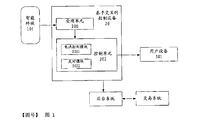
- FIG. 1 is a schematic structural diagram of a module of an interaction-based control device according to a first embodiment of the present invention.
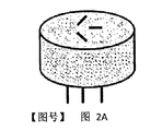
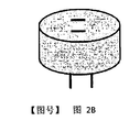
- 2A-2B are schematic diagrams of the appearance of an interaction-based control device, respectively.
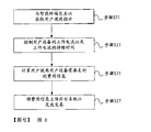
- FIG. 3 is a schematic flowchart of an interactive control method according to a second embodiment of the present invention.
- Coupled and “coupled” are defined to mean directly connected to a component or indirectly connected to a component via another component.
- a first embodiment of the present invention provides an interaction-based control device 20 that is used in conjunction with a user device 301.
- the control device includes an acceptance unit 200 and a control unit 202.
- the acceptance unit 200 interacts with the smart terminal 101 to obtain a user's use instruction on the user equipment 301.
- the acceptance unit 200 includes an RFID module, which interacts with an RFID communication unit on a smart terminal held by a user, so as to obtain a user's use instruction.
- the usage instruction indicates the user's intention or expectation to use the user equipment 301. Further, the usage instruction may also indicate the time the user desires to use the user equipment 301, the working mode of the user equipment 301, and the payment mode desired by the user.
- the user equipment 301 is an Internet of Things device, which may be a shared washing machine, microwave oven, television, computer, or the like.
- an RFID unit By setting an RFID unit, multiple different user equipments 301 can join the same Internet of Things.
- the background that manages the Internet of Things can manage and maintain the various devices connected to the Internet of Things, thereby achieving reasonable scheduling of shared resources.
- the user equipment 301 itself does not include an RFID unit, but joins the Internet of Things through an interaction-based control device 20 that is coupled and used in conjunction with it.
- the control device 20 uses the identification information of the user device 301 to register as a node of the Internet of Things.
- the combination of the control device 20 and the user device 301 serves as a node of the Internet of Things.
- the acceptance unit 200 includes a two-dimensional code identification module, which can read and identify the two-dimensional code displayed on the smart terminal 101 to obtain a user's use instruction. In this way, the user sets its use intention through the App installed on the smart terminal.
- the App generates a two-dimensional code and presents it to the acceptance unit 200, and the acceptance unit 200 parses the two-dimensional code to obtain a usage instruction.
- the control unit 202 is coupled to the acceptance unit 200 and receives a user's use instruction from the acceptance unit 200 and controls the working state of the user equipment 301 based on the use instruction.
- the control unit 202 may be coupled to the receiving unit 200 by using Bluetooth, WIFI, and a communication dedicated line.
- the control unit 202 and the acceptance unit 200 can be integrated into one component, which is then coupled to the user equipment 301 and used in cooperation.
- the control unit 202 may also be physically separated from the receiving unit 200 but still communicatively coupled.
- the control unit 202 includes at least a current control module 2021, and the current control module 2021 can control the working current of the user equipment 301 based on a user usage instruction.
- the control unit may further include a timing module 2022, which can be used to control the duration of the working current.
- the timing module 2022 can cooperate with the current control module 2021 to perform dual control on the working current, that is, the magnitude and duration of the working current.
- the control unit 202 may include a processor.
- the processor may convert the usage indication into the duration of the corresponding working current, or the size of the corresponding working current, or a combination of the two.
- the control unit 202 may determine that the user equipment 301 first continuously works for a first period of time with a first working current, and then continuously works for a second period of time with a second working current, and so on.
- the user's use instruction is transmitted to the above-mentioned control device coupled to the shared washing machine, and the control device determines that the first working current of the washing machine is 30 minutes and the size is 8A This corresponds to the rinsing phase), the second working current of the washing machine lasts for 5 minutes, and the size is 12A (this corresponds to the dehydration phase).
- the control device 20 further includes a billing module (not shown in the drawings), and the billing module will calculate a fee that the user needs to pay to use the user device 301. Understandably, users can choose a payment model that pays first and then uses, or a model that uses first and pays later.
- the user's payment mode selection, as part of the user's use instruction, is also transmitted to the control device 20 coupled to the user device 301 through the RF mode or the two-dimensional code mode. Further, in this mode of paying first and then using, the user's payment information can be obtained by the control device through RF mode or two-dimensional code mode as part of the user's use instruction.
- the billing information is forwarded by the background system to the transaction system for processing to complete the transaction.
- the background system is a background system corresponding to a plurality of control devices 20, which can control the operation and upgrade of a plurality of different control devices, and forward the charging information generated by the different control devices to the transaction system.
- the transaction system is mainly used for functions such as authentication transactions and deductions.
- the control device 20 of the first embodiment described above can be presented as the shape of an adapter, including but not limited to the shape shown in FIGS. 2A-2B.
- the control device 20 is coupled to the user equipment 301 through a first pluggable interface, and is also coupled to an external power source required by the user equipment 301 through a second pluggable interface.
- the external power source may be an AC power grid or a household three-phase AC power.
- the first pluggable interface may be in the form of a socket or a plug, as is the second pluggable interface. Since one end of the control device 20 is coupled to an external power source and the other end is coupled to the user equipment 301, the control device can conveniently control the working current and duration of the user equipment 301.
- At least a part of the system may be implemented using a group of distributed computing devices connected to a communication network, or based on a "cloud".
- multiple computing devices operate together to provide services by using their shared resources.
- Cloud can provide one or more advantages, including: openness, flexibility and scalability, central management, reliability, scalability, optimization of computing resources, aggregation and analysis across multiple The ability of the user's information, the ability to connect across multiple geographic areas, and the ability to use multiple mobile or data network operators for network connectivity.
- the user equipment coupled to it can respond to the user's use demand in a timely manner, and can also automatically complete the settlement of fees, which makes the IoT device have a service acceptance function and the user experience can be significantly improved.
- Such a control device is also conducive to improving the service efficiency of a user equipment group (including multiple shared user equipment), and realizing reasonable scheduling of shared resources.
- a second embodiment of the present invention provides an interactive control method, which includes the following steps S21-S27.
- Step S21 Interact with the smart terminal to obtain a user's use instruction.
- the user's usage instruction can be obtained by interacting with the RFID communication unit of the smart terminal. Alternatively, it can be obtained by reading and identifying the two-dimensional code presented by the smart terminal.
- Step S23 Control the working current of the user equipment and the duration of the working current.
- the user equipment in addition to the size and duration of the working current, other operating parameters of the user equipment may be controlled, such as the waveform of the working current and the timing of the user equipment to start and close.
- other operating parameters of the user equipment may be controlled, such as the waveform of the working current and the timing of the user equipment to start and close.
- it is necessary to analyze the user's usage instructions. During the analysis, not only the user's usage instructions, but also the performance indicators of the relevant user equipment need to be considered. Through analysis, the usage instruction of the user is converted into specific instructions suitable for controlling the operating parameters of the user equipment.
- Step S25 Calculate the cost information that the user needs to pay for using the user equipment.
- Step S27 upload the fee information to the background system to complete the transaction.
- steps S25-27 are optional steps, and are performed only when it is necessary to implement a charging transaction.
- the user's payment information can be taken as a part of the user's use instruction and obtained by the control device through the RF mode or the two-dimensional code mode.
- the IoT device is in a standby state or a shutdown state when the user has not paid, and the control device coupled to the IoT device provides the standby current or does not provide the current of the IoT device by controlling the current magnitude or the current switch.
- the user can choose one of two payment modes, one is a pre-use payment mode (that is, a preset use time period), and the other is to pay after use according to the user's specific use time period.
- An example of the post-use payment model is as follows: before using the IoT device, the user interacts with the acceptance unit once to pass the usage instructions, and after using the IoT device, the user interacts with the IoT device again to calculate the cost information based on the duration of use.
- Figure 3 shows the post-use payment model.
- the user issues a usage instruction through the acceptance unit.
- the user wants to use the washing machine for 10 minutes and pays the washing machine fee for 10 minutes.
- the control device analyzes the usage instruction and provides a certain amount of work to the washing machine. The current lasts for 10 minutes to meet the user's needs. After the use is completed, the washing machine can obtain a standby current from the control device to maintain the standby working state.
- the control device can upload the expense information to the back-end system, and the back-end system communicates with the transaction system to realize the flow of funds.
- the control device uploads the work record of the user device to the back-end system, the back-end system calculates the actual expense information, and communicates with the transaction system to realize the flow of funds.
Landscapes
- Engineering & Computer Science (AREA)
- General Engineering & Computer Science (AREA)
- Physics & Mathematics (AREA)
- General Physics & Mathematics (AREA)
- Automation & Control Theory (AREA)
- Manufacturing & Machinery (AREA)
- Quality & Reliability (AREA)
- Management, Administration, Business Operations System, And Electronic Commerce (AREA)
- Selective Calling Equipment (AREA)
Abstract
一种基于交互的控制设备(20),与用户设备(301)配合使用,其中的控制设备(20)包括:受理单元(20),与智能终端(101)进行交互,以获取用户对用户设备(301)的使用指示;控制单元(202),与受理单元(200)相耦合,以基于使用指示来控制用户设备(301)的工作状态。由此,使得与控制设备(20)耦接的用户设备(301)能够接入物联网并具备业务受理功能,用户的使用体验可获得显著提高,还可促进对共享资源的合理调度。
Description
本发明涉及物联网技术领域,更具体地说,涉及一种基于交互的控制设备以及交互控制方法。
物联网是通过各种信息传感设备,实时采集任何需要监控、连接、互动的物体或过程等各种需要的信息,与互联网相结合而形成的一个网络。其具有以下两种基本应用模式:1、对象的智能标签。通过NFC、二维码、RFID等技术标识特定的对象,用于区分对象个体;此外,通过智能标签还可以用于获得对象物品所包含的扩展信息。2、对象的智能控制。物联网基于云计算平台和智能网络,可以依据传感器网络对所获取的数据进行决策,改变对象的行为、或进行控制和反馈。
然而,即使物联网技术越来越成熟,物联网设备也通常不会具备业务受理功能,而是需要对物联网设备本身进行改进甚至重新设计,才能使物联网设备具备业务受理能力。这种限制在愈加强调用户使用体验的当前,为物联网的普及带来了消极影响。
发明内容
本发明的目的在于提供一种基于交互的控制设备。
为实现上述目的,本发明提供一种技术方案如下:
一种基于交互的控制设备,与用户设备配合使用,控制设备包括:受理单元,与智能终端进行交互,以获取用户对用户设备的使用指示;控制单元,与受理单元相耦合,以基于使用指示来控制用户设备的工作状态。
优选地,控制单元至少包括电流控制模块,电流控制模块控制用户设备的工作电流。
优选地,控制单元还包括定时模块,定时模块用于控制工作电流的持续时间。
优选地,受理单元包括RFID模块,RFID模块与智能终端的RFID通信单元 交互以获取使用指示。
优选地,用户设备为物联网设备。
优选地,控制设备还包括计费模块,计费模块计算用户使用用户设备需要支付的费用信息并上传至后台系统。
优选地,控制设备通过第一可插拔接口与用户设备耦接。
优选地,控制设备还通过第二可插拔接口与用户设备所需的外部电源耦接。
本发明还公开一种交互控制方法,用于促进用户对用户设备的使用,该方法包括:获取用户的使用指示;基于使用指示来控制用户设备的工作状态;其中,获取用户的使用指示包括如下项中的至少一个:与智能终端的RFID通信单元交互以获取使用指示;识别智能终端所生成的二维码以获取使用指示;其中,控制用户设备的工作状态包括如下项中的至少一个:控制用户设备的工作电流;控制工作电流的持续时间。
本发明至少能够实现如下技术效果:通过控制设备来读取并解析用户的使用指示,与控制设备耦接的用户设备能够及时地响应用户的使用需求,并可以自动完成费用的结算,这使得物联网设备具备业务受理功能,用户的使用体验可获得显著提高,以及,促进对共享资源的合理调度。
图1示出本发明第一实施例提供的基于交互的控制设备的模块结构示意图。
图2A-2B分别示出一种基于交互的控制设备的外观示意图。
图3示出本发明第二实施例提供的交互控制方法的流程示意图。
在以下描述中提出具体细节,以便提供对本发明的透彻理解。然而,本领域的技术人员将清楚地知道,即使没有这些具体细节也可实施本发明的实施例。在本发明中,可进行具体的数字引用,例如“第一元件”、“第二装置”等。但是,具体数字引用不应当被理解为必须服从于其字面顺序,而是应被理解为“第一元件”与“第二元件”不同。
本发明所提出的具体细节只是示范性的,具体细节可以变化,但仍然落 入本发明的精神和范围之内。此外,术语“耦合”、“耦接”定义为表示直接连接到组件或者经由另一个组件而间接连接到组件。
以下通过参照附图来描述适于实现本发明的方法、系统和装置的优选实施例。虽然各实施例是针对元件的单个组合来描述,但是应理解,本发明包括所公开元件的所有可能组合。因此,如果一个实施例包括元件A、B和C,而第二实施例包括元件B和D,则本发明也应被认为包括A、B、C或D的其他剩余组合,即使没有明确公开。
如图1所示,本发明第一实施例提供一种基于交互的控制设备20,其与用户设备301配合使用,该控制设备包括受理单元200以及控制单元202。
具体来说,受理单元200与智能终端101进行交互,以获取用户对用户设备301的使用指示。
作为一种实现方式,受理单元200包括RFID模块,其与用户所持有的智能终端上的RFID通信单元进行交互,以便获取用户的使用指示。该使用指示表明用户使用用户设备301的意图或期望,进一步地,该使用指示还可以表明用户期望使用用户设备301的时间、用户设备301的工作模式、以及用户希望的付费模式等。
作为示例,用户设备301是一种物联网设备,其可以为共享式的洗衣机、微波炉、电视机、电脑等。通过设置RFID单元,多台不同用户设备301可以加入同一物联网。除了统计用户对特定设备的使用需求以及监控设备的运行状态以外,管理该物联网的后台能够对接入物联网的各设备进行管理与维护,进而实现共享资源的合理调度。
备选情况下,用户设备301自身不包括RFID单元,而是通过与其耦接而配合使用的基于交互的控制设备20来加入物联网。优选地,控制设备20使用用户设备301的标识信息来注册成为物联网的一个节点。换言之,控制设备20与用户设备301的组合体作为物联网的一个节点。
作为另一种实现方式,受理单元200包括二维码识别模块,该模块能够读取并识别智能终端101上所显示的二维码,从而获得用户的使用指示。在这种方式下,用户通过智能终端上安装的App来设定其使用意图,App生成二维码呈现给受理单元200,受理单元200解析给二维码从而获得使用指示。
控制单元202与受理单元200相耦合,其从受理单元200接收用户的使用指示并基于该使用指示来控制用户设备301的工作状态。
控制单元202可以采用蓝牙、WIFI、通信专线等方式与受理单元200耦合。其中,控制单元202可与受理单元200集成为一个部件,该部件再与用户设备301耦接并配合使用。控制单元202也可与受理单元200在物理上分离但仍通信地耦合。
控制单元202至少包括电流控制模块2021,电流控制模块2021可在用户使用指示的基础上控制用户设备301的工作电流。控制单元还可以包括定时模块2022,定时模块2022能够用于控制工作电流的持续时间。定时模块2022可与电流控制模块2021协同作用,来对工作电流进行双重控制,即,工作电流的大小以及持续时间。应理解,为了根据用户的使用指示来控制工作电流,控制单元202内可以包括处理器。作为示例,处理器可将使用指示转换为对应的工作电流的持续时间,或者对应的工作电流的大小,或两者的组合。
优选情况下,使用指示被转为工作电流的持续时间以及幅度信息的组合。例如,根据用户使用指示,控制单元202可能确定用户设备301先以第一工作电流持续工作第一时间段,再以第二工作电流持续工作第二时间段,诸如此类。作为一个具体的应用示例,在用户期望使用共享洗衣机时,用户的使用指示被传达至与共享洗衣机耦接的上述控制设备,控制设备确定洗衣机的第一工作电流持续为30分钟,大小为8A(这对应于漂洗阶段),洗衣机的第二工作电流持续为5分钟,大小为12A(这对应于脱水阶段)。
作为上述实施例的进一步改进,控制设备20还包括计费模块(附图未示出),计费模块将计算用户使用用户设备301需要支付的费用。可理解,用户能够选择先付费再使用的付费模式,也可选择先使用后付费的模式。用户的付费模式选择作为用户使用指示的一部分,也通过RF模式或二维码模式传递到与用户设备301耦接的控制设备20。进一步地,在先付费再使用这一模式下,用户的付费信息可作为用户使用指示的一部分,通过RF模式或二维码模式由控制设备获取。
计费信息由后台系统转发到交易系统进行处理,完成本次交易。这里,后台系统是与多个控制设备20对应的后台系统,其能够控制多个不同的控制设 备的运行与升级,并将不同的控制设备生成的计费信息转发至交易系统。交易系统主要用于负责认证交易,扣费等功能。
上述第一实施例的控制设备20能够呈现为转接头的外形,包括但不限于图2A-2B所示的外形。控制设备20通过第一可插拔接口与用户设备301耦接,并且还通过第二可插拔接口与用户设备301所需的外部电源耦接,外部电源可以为交流电网或家用三相交流电。第一可插拔接口可以为插口或插头形式,第二可插拔接口同样如此。由于这种控制设备20一端与外部电源耦接,另一端与用户设备301耦接,所以控制设备能够方便地控制用户设备301的工作电流大小以及持续时间。
在本发明的一些实施例中,系统的至少一部分可采用通信网络所连接的一组分布式计算装置来实现,或,基于“云”来实现。在这种系统中,多个计算装置共同操作,以通过使用其共享资源来提供服务。
基于“云”的实现可提供一个或多个优点,包括:开放性、灵活性和可扩展性、可中心管理、可靠性、可缩放性、对计算资源所优化、具有聚合和分析跨多个用户的信息的能力、跨多个地理区域进行连接、以及将多个移动或数据网络运营商用于网络连通性的能力。
利用上述控制设备,与其耦接的用户设备能够及时地响应用户的使用需求,还可以自动完成费用的结算,这使得物联网设备具备业务受理功能,用户的使用体验可获得显著提高。这种控制设备还有利于提高用户设备组(包括多个共享式用户设备)的服务效率,实现共享资源的合理调度。
如图3所示,本发明第二实施例提供一种交互控制方法,其包括如下各步骤S21-S27。
步骤S21:与智能终端交互以获取用户的使用指示。
其中,用户的使用指示可通过与智能终端的RFID通信单元交互的方式来获取,备选地,可以通过读取并识别智能终端呈现的二维码来获取。
步骤S23:控制用户设备的工作电流以及工作电流的持续时间。
其中,除了工作电流的大小和持续时间以外,还可能对用户设备的其他运行参数进行控制,例如,工作电流的波形、用户设备的定时启动与关闭。为了控制用户设备的上述运行参数,需要对用户的使用指示进行解析,在解析的过程 中,不仅考虑用户的使用指示,还需要考虑相关用户设备的性能指标。通过解析,将用户的使用指示转换为适于控制用户设备的运行参数的具体指令。
步骤S25:计算用户使用用户设备需要支付的费用信息。
步骤S27:将费用信息上传后台系统以完成交易。
上述步骤S25-27是可选的步骤,在需要实现计费交易的场合下才执行。其中,在使用前付费模式下,用户的付费信息可作为用户使用指示的一部分,通过RF模式或二维码模式由控制设备获取。
根据一种具体的实施方式,物联网设备在用户尚未付费时,处于待机状态或关机状态,与其耦接的控制设备通过控制电流大小或电流开关,提供物联网设备的待机电流或不提供电流。用户可选择两种付费模式其中之一,一种是使用前付费模式(即,预设使用时长),另一种是根据用户的具体使用时长,使用后付费。使用后付费模式示例如下:用户在使用物联网设备前先与受理单元进行一次交互以传递使用指示,用户使用完物联网设备后再次与物联网设备进行交互,以根据使用时长计算费用信息。图3所示出的即为使用后付费模式。
备选地,按照使用前付费模式,用户通过受理单元发出使用指示,比如,用户希望使用洗衣机10分钟,并付10分钟洗衣机费用,控制设备解析该使用指示,并通过向洗衣机提供一定大小的工作电流持续达10分钟来满足用户的使用需求。在本次使用完成后,洗衣机可从控制设备获得待机电流来保持待机工作状态。
为了结算费用,控制设备可以将费用信息上传后台系统,后台系统再与交易系统进行通信,实现资金的流转。备选地,控制设备将用户设备的工作记录上传后台系统,由后台系统来计算实际的费用信息,并与交易系统通信来实现资金的流转。
应理解,上述第二实施例提供的方法的各个步骤可以进行组合、省略或以不同的先后顺序来执行,只要能够实现本发明的技术效果,均应落入本发明的范围内。
上述说明仅针对于本发明的优选实施例,并不在于限制本发明的保护范围。本领域技术人员可能作出各种变形设计,而不脱离本发明的思想及附随的权利要求。
Claims (13)
- 一种基于交互的控制设备,与用户设备配合使用,所述控制设备包括:受理单元,与智能终端进行交互,以获取用户对所述用户设备的使用指示;控制单元,与所述受理单元相耦合,以基于所述使用指示来控制所述用户设备的工作状态。
- 根据权利要求1所述的控制设备,其特征在于,所述控制单元至少包括电流控制模块,所述电流控制模块控制所述用户设备的工作电流。
- 根据权利要求2所述的控制设备,其特征在于,所述控制单元还包括定时模块,所述定时模块用于控制所述工作电流的持续时间。
- 根据权利要求1所述的控制设备,其特征在于,所述受理单元包括RFID模块,所述RFID模块与智能终端的RFID通信单元交互以获取所述使用指示。
- 根据权利要求1所述的控制设备,其特征在于,所述受理单元包括二维码识别模块,所述二维码识别模块读取和/或识别智能终端所生成的二维码以获取所述使用指示。
- 根据权利要求1至5中任一项所述的控制设备,其特征在于,所述用户设备不包括RFID单元。
- 根据权利要求6所述的控制设备,其特征在于,所述控制设备被加入物联网。
- 根据权利要求7所述的控制设备,其特征在于,所述控制设备还包括计费模块,所述计费模块计算用户使用所述用户设备需要支付的费用信息并上传至后台系统。
- 根据权利要求1所述的控制设备,其特征在于,所述控制设备通过第一可插拔接口与所述用户设备耦接。
- 根据权利要求9所述的控制设备,其特征在于,所述控制设备还通过第二可插拔接口与所述用户设备所需的外部电源耦接。
- 一种交互控制方法,用于促进用户对用户设备的使用,所述方法包括:获取用户的使用指示;基于所述使用指示来控制所述用户设备的工作状态;其中,获取用户的使用指示包括如下项中的至少一个:与智能终端的RFID通信单元交互以获取所述使用指示;识别智能终端所生成的二维码以获取所述使用指示;其中,控制用户设备的工作状态包括如下项中的至少一个:控制所述用户设备的工作电流;控制所述工作电流的持续时间。
- 根据权利要求11所述的方法,其特征在于,所述方法还包括:计算用户使用所述用户设备需要支付的费用信息。
- 根据权利要求12所述的方法,其特征在于,所述方法还包括:将所述费用信息和/或所述用户设备的工作记录上传后台系统。
Applications Claiming Priority (2)
| Application Number | Priority Date | Filing Date | Title |
|---|---|---|---|
| CN201810986905.9A CN109507895B (zh) | 2018-08-28 | 2018-08-28 | 基于交互的控制设备与交互控制方法 |
| CN201810986905.9 | 2018-08-28 |
Publications (1)
| Publication Number | Publication Date |
|---|---|
| WO2020042963A1 true WO2020042963A1 (zh) | 2020-03-05 |
Family
ID=65745671
Family Applications (1)
| Application Number | Title | Priority Date | Filing Date |
|---|---|---|---|
| PCT/CN2019/101469 Ceased WO2020042963A1 (zh) | 2018-08-28 | 2019-08-20 | 基于交互的控制设备与交互控制方法 |
Country Status (3)
| Country | Link |
|---|---|
| CN (1) | CN109507895B (zh) |
| TW (1) | TWI764035B (zh) |
| WO (1) | WO2020042963A1 (zh) |
Cited By (1)
| Publication number | Priority date | Publication date | Assignee | Title |
|---|---|---|---|---|
| CN114596667A (zh) * | 2022-03-08 | 2022-06-07 | 北京物资学院 | 一种数据共享方法、系统及计算机存储介质 |
Families Citing this family (2)
| Publication number | Priority date | Publication date | Assignee | Title |
|---|---|---|---|---|
| CN109507895B (zh) * | 2018-08-28 | 2022-04-19 | 中国银联股份有限公司 | 基于交互的控制设备与交互控制方法 |
| CN111984955A (zh) * | 2020-08-20 | 2020-11-24 | 浙江荣泰健康电器有限公司 | 一种共享按摩椅的使用方法 |
Citations (10)
| Publication number | Priority date | Publication date | Assignee | Title |
|---|---|---|---|---|
| US20020101363A1 (en) * | 2001-01-31 | 2002-08-01 | Honda Giken Kogyo Kabushiki Kaisha | Vehicle managing system and vehicle managing method |
| CN106707868A (zh) * | 2016-12-30 | 2017-05-24 | 安徽朋德信息科技有限公司 | 共享实验仪器的电源控制方法和电源控制系统 |
| CN107170137A (zh) * | 2017-05-23 | 2017-09-15 | 康体佳智能科技(深圳)有限公司 | 一种共享洗衣机系统 |
| CN107527439A (zh) * | 2017-06-15 | 2017-12-29 | 青岛赛里斯能源科技有限公司 | 基于无线网络分享或共享充电桩的管理系统及其控制方法和装置 |
| CN207156977U (zh) * | 2017-09-12 | 2018-03-30 | 苏州桓动网络科技有限公司 | 一种基于移动支付的智能共享充电车桩 |
| CN107944943A (zh) * | 2017-10-23 | 2018-04-20 | 青岛海尔股份有限公司 | 空调共享系统及其运行方法 |
| CN108053284A (zh) * | 2017-12-21 | 2018-05-18 | 美的集团股份有限公司 | 家电设备的租赁方法、装置及服务器 |
| CN108173956A (zh) * | 2018-01-02 | 2018-06-15 | 深圳市康瑞兴科技有限公司 | 一种电路控制开关的控制方法、控制系统以及共享系统 |
| CN108320223A (zh) * | 2018-04-11 | 2018-07-24 | 陈成 | 基于物联网远程控制的共享设备系统、方法以及共享空气净化器装置 |
| CN109507895A (zh) * | 2018-08-28 | 2019-03-22 | 中国银联股份有限公司 | 基于交互的控制设备与交互控制方法 |
Family Cites Families (26)
| Publication number | Priority date | Publication date | Assignee | Title |
|---|---|---|---|---|
| JP2011029919A (ja) * | 2009-07-24 | 2011-02-10 | Sharp Corp | 情報端末装置、情報端末装置を用いた家庭用機器制御方法、制御プログラム |
| US9219364B2 (en) * | 2010-03-15 | 2015-12-22 | Tokyo Electric Power Company, Incorporated | Public power supply system |
| ITTO20120738A1 (it) * | 2012-08-21 | 2014-02-22 | Indesit Co Spa | "sistema elettrodomestico" |
| ITBO20120705A1 (it) * | 2012-12-21 | 2014-06-22 | I M A Ind Macchine Automatic He S P A | Sistema e metodo di controllo di una macchina automatica |
| US9640174B2 (en) * | 2013-01-02 | 2017-05-02 | Lg Electronics Inc. | Home appliance and operation method thereof |
| CN103147259A (zh) * | 2013-03-17 | 2013-06-12 | 孙广辉 | 公用智能化洗衣机控制器系统及结构改进方法 |
| WO2015183014A1 (en) * | 2014-05-28 | 2015-12-03 | Samsung Electronics Co., Ltd. | Apparatus and method for controlling internet of things devices |
| CN104125291B (zh) * | 2014-08-06 | 2017-12-01 | 山东建筑大学 | 一种电气设备物联网节点下对应电气设备配置方法和系统 |
| US9912365B2 (en) * | 2014-10-16 | 2018-03-06 | Lg Electronics Inc. | Watch type terminal and method for controlling the same |
| CN105872941B (zh) * | 2015-01-21 | 2020-06-26 | 阿里巴巴集团控股有限公司 | 一种无线外围设备接入或移除方法及装置 |
| JP2016133294A (ja) * | 2015-01-22 | 2016-07-25 | ジョンソンコントロールズ ヒタチ エア コンディショニング テクノロジー(ホンコン)リミテッド | 空調機の保守・メンテナンスシステム及びその方法 |
| KR101679271B1 (ko) * | 2015-06-09 | 2016-11-24 | 엘지전자 주식회사 | 이동단말기 및 그 제어방법 |
| CN105590046B (zh) * | 2015-11-23 | 2018-10-23 | 中国银联股份有限公司 | 基于特征识别的身份认证方法 |
| CN105406536B (zh) * | 2015-12-07 | 2018-01-12 | 湖南深拓智能设备股份有限公司 | 一种使用互联网的智能移动充电系统及方法 |
| CN105711934A (zh) * | 2016-01-13 | 2016-06-29 | 厦门驭波超声技术有限公司 | 多功能智能快递盒 |
| WO2017126740A1 (ko) * | 2016-01-22 | 2017-07-27 | 삼성전자 주식회사 | 단말 장치, 원격 제어 시스템 및 제어 방법 |
| CN105791558A (zh) * | 2016-02-26 | 2016-07-20 | 努比亚技术有限公司 | 移动终端及其控制终端设备的方法 |
| CN105599633A (zh) * | 2016-03-18 | 2016-05-25 | 上海巽骑骥网络科技有限公司 | 自助式电动二轮车智能充电桩 |
| WO2017219188A1 (zh) * | 2016-06-20 | 2017-12-28 | 易晓阳 | 一种智能家居设备控制系统 |
| CN106926736A (zh) * | 2017-04-20 | 2017-07-07 | 温州易充绿能源科技有限公司 | 一种电瓶车用智能充电站 |
| TR201712927A2 (tr) * | 2017-08-29 | 2017-09-21 | Sueleyman Hilmi Yilmaz | Akıllı Fiş-Priz Sistemi |
| CN207567506U (zh) * | 2017-10-18 | 2018-07-03 | 淘洗洗智能科技(上海)有限公司 | 一种智能共享洗衣机系统 |
| CN107888691A (zh) * | 2017-11-17 | 2018-04-06 | 成都正光恒电子科技有限责任公司 | 一种物联网云终端计算机 |
| CN207752539U (zh) * | 2017-12-27 | 2018-08-21 | 白代凤 | 一种共享智能车位锁 |
| CN108334003A (zh) * | 2018-03-26 | 2018-07-27 | 四川久久合创信息技术有限公司 | 一种基于无线通信的智能家电控制器 |
| CN108399684A (zh) * | 2018-05-15 | 2018-08-14 | 济南美丰环保产品有限公司 | 一种智能共享取水系统 |
-
2018
- 2018-08-28 CN CN201810986905.9A patent/CN109507895B/zh active Active
-
2019
- 2019-08-20 WO PCT/CN2019/101469 patent/WO2020042963A1/zh not_active Ceased
- 2019-08-22 TW TW108130024A patent/TWI764035B/zh active
Patent Citations (10)
| Publication number | Priority date | Publication date | Assignee | Title |
|---|---|---|---|---|
| US20020101363A1 (en) * | 2001-01-31 | 2002-08-01 | Honda Giken Kogyo Kabushiki Kaisha | Vehicle managing system and vehicle managing method |
| CN106707868A (zh) * | 2016-12-30 | 2017-05-24 | 安徽朋德信息科技有限公司 | 共享实验仪器的电源控制方法和电源控制系统 |
| CN107170137A (zh) * | 2017-05-23 | 2017-09-15 | 康体佳智能科技(深圳)有限公司 | 一种共享洗衣机系统 |
| CN107527439A (zh) * | 2017-06-15 | 2017-12-29 | 青岛赛里斯能源科技有限公司 | 基于无线网络分享或共享充电桩的管理系统及其控制方法和装置 |
| CN207156977U (zh) * | 2017-09-12 | 2018-03-30 | 苏州桓动网络科技有限公司 | 一种基于移动支付的智能共享充电车桩 |
| CN107944943A (zh) * | 2017-10-23 | 2018-04-20 | 青岛海尔股份有限公司 | 空调共享系统及其运行方法 |
| CN108053284A (zh) * | 2017-12-21 | 2018-05-18 | 美的集团股份有限公司 | 家电设备的租赁方法、装置及服务器 |
| CN108173956A (zh) * | 2018-01-02 | 2018-06-15 | 深圳市康瑞兴科技有限公司 | 一种电路控制开关的控制方法、控制系统以及共享系统 |
| CN108320223A (zh) * | 2018-04-11 | 2018-07-24 | 陈成 | 基于物联网远程控制的共享设备系统、方法以及共享空气净化器装置 |
| CN109507895A (zh) * | 2018-08-28 | 2019-03-22 | 中国银联股份有限公司 | 基于交互的控制设备与交互控制方法 |
Cited By (2)
| Publication number | Priority date | Publication date | Assignee | Title |
|---|---|---|---|---|
| CN114596667A (zh) * | 2022-03-08 | 2022-06-07 | 北京物资学院 | 一种数据共享方法、系统及计算机存储介质 |
| CN114596667B (zh) * | 2022-03-08 | 2023-08-11 | 北京物资学院 | 一种数据共享方法、系统及计算机存储介质 |
Also Published As
| Publication number | Publication date |
|---|---|
| TW202029118A (zh) | 2020-08-01 |
| CN109507895B (zh) | 2022-04-19 |
| CN109507895A (zh) | 2019-03-22 |
| TWI764035B (zh) | 2022-05-11 |
Similar Documents
| Publication | Publication Date | Title |
|---|---|---|
| CN210109947U (zh) | 一种基于蓝牙缴费的预付费物联网水表 | |
| WO2020042963A1 (zh) | 基于交互的控制设备与交互控制方法 | |
| CN107615343A (zh) | 一种基于移动终端通信的电能表系统 | |
| CN109624775A (zh) | 一种基于NBIoT物联网的充电桩系统 | |
| US20190067999A1 (en) | Wireless charging management system and wireless power transmitting terminal | |
| CN103529788A (zh) | 远程云家电控制设备 | |
| CN102316151A (zh) | 一种智能感知互动综合服务系统 | |
| Karthikeyan et al. | Iot based real-time residential energy meter monitoring system | |
| CN105069916B (zh) | 一种利用智能电表进行代扣费的方法及系统 | |
| CN107633461A (zh) | 一种营业厅收电费系统 | |
| CN105338550B (zh) | 一种用于无线网络的连接的管理方法和装置 | |
| KR20130103793A (ko) | 무선전력 공급 장치, 무선전력 수신이 가능한 전자 기기 및 무선전력 전송 제어 방법 | |
| CN105954578A (zh) | 一种具有数据完整响应及时信息安全的抄表系统 | |
| JP7173674B2 (ja) | 充電制御装置、充電管理システム、方法及びプログラム | |
| CN207181478U (zh) | 一种云端管理的智能电表 | |
| CN204242391U (zh) | 智能手机蓝牙转红外抄表装置 | |
| EP3609153B1 (en) | Maintenance equipment management method, server and computer-readable storage medium | |
| CN106921686A (zh) | 管理计量数据的方法、装置和系统 | |
| HK40003665A (zh) | 基於交互的控制设备与交互控制方法 | |
| HK40003665B (zh) | 基於交互的控制设备与交互控制方法 | |
| KR20180003334A (ko) | 스마트 콘센트 | |
| CN100384192C (zh) | 一种宽带智能上网业务的实现方法 | |
| Hussain et al. | IoT residential appliance monitoring and controlling system using MQTT protocol | |
| TWI785513B (zh) | 具可變能源管理方案之電動車充電管理方法及系統 | |
| CN109191204A (zh) | 云数据系统中虚拟机的计费管理方法和装置 |
Legal Events
| Date | Code | Title | Description |
|---|---|---|---|
| 121 | Ep: the epo has been informed by wipo that ep was designated in this application |
Ref document number: 19855740 Country of ref document: EP Kind code of ref document: A1 |
|
| NENP | Non-entry into the national phase |
Ref country code: DE |
|
| 122 | Ep: pct application non-entry in european phase |
Ref document number: 19855740 Country of ref document: EP Kind code of ref document: A1 |