WO2020040137A1 - アクセサリおよびプログラム - Google Patents
アクセサリおよびプログラム Download PDFInfo
- Publication number
- WO2020040137A1 WO2020040137A1 PCT/JP2019/032443 JP2019032443W WO2020040137A1 WO 2020040137 A1 WO2020040137 A1 WO 2020040137A1 JP 2019032443 W JP2019032443 W JP 2019032443W WO 2020040137 A1 WO2020040137 A1 WO 2020040137A1
- Authority
- WO
- WIPO (PCT)
- Prior art keywords
- aperture
- value
- control unit
- drive
- lens
- Prior art date
- Legal status (The legal status is an assumption and is not a legal conclusion. Google has not performed a legal analysis and makes no representation as to the accuracy of the status listed.)
- Ceased
Links
Images


Classifications
-
- G—PHYSICS
- G02—OPTICS
- G02B—OPTICAL ELEMENTS, SYSTEMS OR APPARATUS
- G02B7/00—Mountings, adjusting means, or light-tight connections, for optical elements
- G02B7/02—Mountings, adjusting means, or light-tight connections, for optical elements for lenses
-
- G—PHYSICS
- G02—OPTICS
- G02B—OPTICAL ELEMENTS, SYSTEMS OR APPARATUS
- G02B7/00—Mountings, adjusting means, or light-tight connections, for optical elements
- G02B7/02—Mountings, adjusting means, or light-tight connections, for optical elements for lenses
- G02B7/04—Mountings, adjusting means, or light-tight connections, for optical elements for lenses with mechanism for focusing or varying magnification
- G02B7/08—Mountings, adjusting means, or light-tight connections, for optical elements for lenses with mechanism for focusing or varying magnification adapted to co-operate with a remote control mechanism
-
- G—PHYSICS
- G03—PHOTOGRAPHY; CINEMATOGRAPHY; ANALOGOUS TECHNIQUES USING WAVES OTHER THAN OPTICAL WAVES; ELECTROGRAPHY; HOLOGRAPHY
- G03B—APPARATUS OR ARRANGEMENTS FOR TAKING PHOTOGRAPHS OR FOR PROJECTING OR VIEWING THEM; APPARATUS OR ARRANGEMENTS EMPLOYING ANALOGOUS TECHNIQUES USING WAVES OTHER THAN OPTICAL WAVES; ACCESSORIES THEREFOR
- G03B17/00—Details of cameras or camera bodies; Accessories therefor
- G03B17/02—Bodies
- G03B17/12—Bodies with means for supporting objectives, supplementary lenses, filters, masks, or turrets
- G03B17/14—Bodies with means for supporting objectives, supplementary lenses, filters, masks, or turrets interchangeably
-
- G—PHYSICS
- G03—PHOTOGRAPHY; CINEMATOGRAPHY; ANALOGOUS TECHNIQUES USING WAVES OTHER THAN OPTICAL WAVES; ELECTROGRAPHY; HOLOGRAPHY
- G03B—APPARATUS OR ARRANGEMENTS FOR TAKING PHOTOGRAPHS OR FOR PROJECTING OR VIEWING THEM; APPARATUS OR ARRANGEMENTS EMPLOYING ANALOGOUS TECHNIQUES USING WAVES OTHER THAN OPTICAL WAVES; ACCESSORIES THEREFOR
- G03B17/00—Details of cameras or camera bodies; Accessories therefor
- G03B17/56—Accessories
-
- G—PHYSICS
- G03—PHOTOGRAPHY; CINEMATOGRAPHY; ANALOGOUS TECHNIQUES USING WAVES OTHER THAN OPTICAL WAVES; ELECTROGRAPHY; HOLOGRAPHY
- G03B—APPARATUS OR ARRANGEMENTS FOR TAKING PHOTOGRAPHS OR FOR PROJECTING OR VIEWING THEM; APPARATUS OR ARRANGEMENTS EMPLOYING ANALOGOUS TECHNIQUES USING WAVES OTHER THAN OPTICAL WAVES; ACCESSORIES THEREFOR
- G03B7/00—Control of exposure by setting shutters, diaphragms or filters, separately or conjointly
- G03B7/20—Control of exposure by setting shutters, diaphragms or filters, separately or conjointly in accordance with change of lens
-
- H—ELECTRICITY
- H04—ELECTRIC COMMUNICATION TECHNIQUE
- H04N—PICTORIAL COMMUNICATION, e.g. TELEVISION
- H04N23/00—Cameras or camera modules comprising electronic image sensors; Control thereof
- H04N23/60—Control of cameras or camera modules
Definitions
- the present invention relates to an accessory that can be mounted between an interchangeable lens and a camera body and that operates an aperture of the interchangeable lens.
- An accessory is an accessory that can be mounted between a lens device having an aperture and an imaging device, and a control unit that controls communication with each of the lens device and the imaging device;
- the control unit transmits a control signal for driving the aperture to the lens device in accordance with the operation of the operation member, and sets a variable range of the set value of the aperture. And transmitting information on the information to the imaging device.
- a program for detecting an operation of an operation member of an accessory by a computer of an accessory that can be mounted between a lens device having an aperture with a variable aperture diameter and an imaging device. Transmitting a control signal for driving the aperture to the lens device according to a detection result in the step, and transmitting information on a variable range of the set value of the aperture to the imaging device. And is executed.
- FIG. 1 is a block diagram of a camera system (imaging system) 1.
- the camera system 1 includes an interchangeable lens (lens device) 2, a camera body (imaging device) 3, and a lens adapter (accessory) 4 that can be mounted between the interchangeable lens 2 and the camera body 3.
- the interchangeable lens 2 is detachable from the camera body 3.
- the interchangeable lens 2 can be mounted on the camera body 3 via the lens adapter 4.
- the lens adapter 4 has a connection mount that enables communication (lens-camera communication) between the interchangeable lens 2 and the camera body 3 at both ends, and one end is detachable from the interchangeable lens 2. The other end is detachable from the camera body 3. With such a configuration, the interchangeable lens 2 and the camera body 3 can be indirectly connected via the lens adapter 4.
- the interchangeable lens 2 and the camera body 3 have different flange backs, and the lens adapter 4 is designed to fill the difference between the flange backs.
- the lens adapter 4 may be an adapter used for the interchangeable lens 2 and the camera body 3 having no difference in design of the flange back represented by an extender.
- the lens adapter 4 is an extender
- the interchangeable lens 2 or the camera body 3 is configured to be able to recognize that the lens adapter 4 is an extender and extender information such as its magnification.
- the optical information handled by the interchangeable lens 2 or the camera body 3 is appropriately converted so that appropriate optical information such as a change in focal length and a change in aperture value due to the interposition of the lens adapter 4 as an extender can be handled. , Or the data is preferably switched.
- the interchangeable lens 2, the lens adapter 4, and the camera body 3 are each mechanically connected via a mount (connector) (not shown).
- a communication unit 27 is provided on a connector of the interchangeable lens 2.
- a communication unit 33 is provided on a connector of the camera body 3.
- Communication units 45 and 46 are provided on the connector of the lens adapter 4.
- the lens adapter 4 includes an adapter CPU 41, communication units 45 and 46, and an operation member 43.
- the operation member 43 is an input device that is operable by a user and specifies (instructs) a driving direction (a direction of increasing or decreasing the opening diameter) and a driving amount of the diaphragm 23.
- the operation member 43 is an aperture ring.
- the aperture ring (operation member 43) is an operation ring arranged along the outer periphery of the housing of the lens adapter 4, and specifies the drive direction of the aperture 23 by its rotation direction, and controls the drive amount of the aperture 23 by its rotation amount. Can be specified.
- the operating member 43 is not limited to the aperture ring, and may be configured by another input device such as a rotary selector, an analog stick, or a seesaw switch (seesaw button).
- the seesaw switch is an operation button configured to be capable of inputting at least two inputs, and the driving direction of the aperture is operated by the operated button, and the driving of the aperture is performed according to the pressing amount or pressing time of the button. The amount and drive speed can be determined.
- the adapter CPU 41 (control means) is an adapter control means for controlling all the controls in the lens adapter 4 and includes a microcomputer and the like.
- the adapter CPU 41 has built-in storage means (memory) such as a RAM, a ROM, and an EEPROM, and has a communication unit 42 and an aperture control unit 44.
- the communication unit 42 controls communication with the camera body 3 and communication with each of the interchangeable lenses 2.
- the communication unit 42 receives a signal (data) transmitted from the camera body 3 and transmits the signal or a signal based on the signal to the interchangeable lens 2 as necessary.
- the communication unit 42 receives the signal (data) transmitted from the interchangeable lens 2 and transmits the signal or a signal based on the signal to the camera body 3 as necessary.
- the communication unit 42 spontaneously performs communication with the interchangeable lens 2 and communication with the camera body 3 as needed, and details thereof will be described later.
- the aperture control unit 44 acquires operation information (output signal of the operation member 43) from an operation member (aperture ring) 43 based on a user's operation, and controls driving of the aperture 23.
- Such drive control of the diaphragm 23 based on the operation of the operation member 43 is also referred to as manual diaphragm control. The details of this process will be described later.
- the interchangeable lens 2 includes a lens CPU 20, an imaging optical system 21, a focus drive circuit 22, an aperture (aperture blades, an aperture mechanism) 23, a stepping motor (drive unit) 25 for driving the aperture 23, an aperture drive circuit 26, and It has a communication unit 27.
- the lens CPU 20 is a lens control unit that controls all parts of the interchangeable lens 2 and includes a microcomputer and the like.
- the lens CPU 20 has built-in storage means such as a RAM, a ROM, and an EEPROM, and controls the driving of the stepping motor 25 via the aperture driving circuit 26.
- the stepping motor 25 and the aperture driving circuit 26 constitute an aperture driving mechanism for driving the aperture 23.
- the aperture drive circuit 26 drives the stepping motor 25 to change the aperture value of the aperture 23 to change the aperture value (F value) and adjust the light amount.
- the driving means of the diaphragm 23 is not limited to the stepping motor 25, and another electromagnetic motor such as a DC motor or an AC motor may be used.
- the communication unit 27 has a plurality of communication terminals for performing communication between the lens CPU 20 and the camera CPU 30, and transmits and receives focus detection information, photometric information, ID information, and the like.
- a lens adapter 4 is interposed between the lens CPU 20 and the camera CPU 30. Therefore, the lens CPU 20 communicates with the adapter CPU 41 via the communication unit 27 and the communication unit 45 of the lens adapter 4.
- the camera body 3 includes a camera CPU 30, a control system power supply 31, a drive system power supply 32, a communication unit 33, a lens attachment detection unit 34, a focus detection unit 35, and an image sensor 36.
- the communication unit 33 has a plurality of communication terminals for performing communication between the camera CPU 30 and the lens CPU 20, and transmits and receives focus detection information, photometric information, ID information, and the like.
- the lens adapter 4 is interposed between the camera CPU 30 and the lens CPU 20. For this reason, the camera CPU 30 communicates with the adapter CPU 41 via the communication unit 33 and the communication unit 46 of the lens adapter 4.
- the operation member (aperture ring) 43 will be described.
- the operation member 43 has a built-in rotation detection mechanism.
- the adapter CPU 41 aperture control unit 44
- the rotation detection mechanism includes, but is not limited to, a photoelectric or magnetic rotary encoder, an optical or magnetic encoder, or an encoder including a substrate on which a conductive pattern is printed and a conductive brush. It is not something to be done.
- FIG. 2 is a sequence diagram of the manual aperture control.
- the aperture control unit 44 monitors (detects) the operation amount and operation direction of the operation member 43 by the operation of the user. Upon receiving the operation detection (SEQ1) of the operation member 43, the aperture control unit 44 performs a drive amount and drive direction conversion process of the aperture 23. The aperture control unit 44 converts the operation amount and operation direction of the operation member 43 into the drive amount and drive direction of the aperture 23 in the aperture drive amount and drive direction conversion process. At this time, the aperture control unit 44 calculates the relative drive amount of the aperture 23 based on the operation amount of the operation member 43, and determines the drive direction of the aperture 23 based on the operation direction of the operation member 43. In the present embodiment, the drive speed of the aperture 23 in the manual aperture control uses an arbitrary fixed value. For this reason, in the present embodiment, the aperture control unit 44 only needs to transmit at least the driving direction and the driving amount of the aperture 23.
- the aperture control unit 44 executes an aperture drive request (SEQ2) and (SEQ3) via the communication unit 42 using the above-described drive direction, drive amount, and drive speed of the aperture 23.
- SEQ2 aperture drive request
- SEQ3 aperture drive request
- the method of determining the driving direction, the driving amount, and the driving speed of the diaphragm 23 based on the detection of the operation of the operation member 43 by the diaphragm control unit 44 will be described later in detail.
- the lens CPU 20 controls the driving of the diaphragm 23 (performs diaphragm driving control) in accordance with the requested driving direction, driving amount, and driving speed based on the diaphragm driving request (SEQ3) received from the adapter CPU 41.
- the adapter CPU 41 sets the upper brightness limit and the lower brightness limit (minimum F3.2, maximum F3.2) based on the current aperture value (current F3.2) received from the lens CPU 20. Then, the adapter CPU 41 transmits the current aperture value, the brightness upper limit value, and the brightness lower limit value to the camera CPU 30 as optical information. As described above, since the optical information request is transmitted from the camera CPU 30 even during the aperture drive control, the communication unit 42 of the adapter CPU 41 executes SEQ8 to SEQ10 and transmits the optical information response (SEQ11), as described above.
- the aperture control unit 44 monitors (detects) the operation amount and operation direction of the operation member 43, and counts the operation amount and operation direction of the operation member 43 detected per unit time.
- the counting method of the present invention is not limited to this, and may be a method of performing aperture drive amount and drive direction conversion processing every time a predetermined operation amount is detected.
- an arbitrary fixed value is used as the driving speed of the diaphragm 23 in the manual diaphragm control.
- the aperture control unit 44 executes the aperture drive requests (SEQ2) and (SEQ3) via the communication unit 42.
- the lens CPU 20 that has received the aperture drive request (SEQ3) controls the drive of the aperture 23 according to the requested drive direction, drive amount, and drive speed.
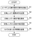
- FIG. 3 is a flowchart of manual aperture control. Each step in FIG. 3 is executed by the adapter CPU 41 (communication unit 42, aperture control unit 44) according to a program.
- step S1 the aperture control unit 44 detects an operation of the operation member 43 by the user (operation detection SEQ1). Subsequently, in step S2, the aperture control unit 44 determines the drive amount and the drive direction of the aperture 23 based on the operation amount and the operation direction of the operation member 43. Then, the communication unit 42 transmits the drive amount and the drive direction determined by the aperture control unit 44 to the interchangeable lens 2 (the lens CPU 20) as a drive command (aperture drive requests SEQ2 and SEQ3).
- the drive command is a control signal for driving the aperture 23.
- step S3 the communication unit 42 requests the lens CPU 20 for the current F value (current aperture value) of the aperture 23 in response to the optical information request SEQ4 from the camera CPU 30 (current aperture value request SEQ5).
- step S4 the communication unit 42 receives the current F value of the aperture 23 (current aperture value response SEQ6) from the lens CPU 20.
- step S5 the communication unit transmits optical information to the camera body (camera CPU 30) (optical information response SEQ7).
- the manual aperture function can be realized even in the camera system 1 in which the interchangeable lens 2 having no manual aperture function and the camera body 3 are combined.
- the lens adapter 4 notifies the camera body 3 of the upper limit value and the lower limit value of the F value as information on the variable range of the set value of the aperture 23, respectively, as the current F value.
- the AE process in the camera body 3 from issuing a drive command to the diaphragm 23 in order to make the exposure constant.
- a process for changing the parameter setting (for example, shutter time or ISO setting) related to exposure other than the aperture drive control to make the exposure constant is performed. In other words, it is possible to suppress the issuance of the aperture drive request from the camera CPU 30 while allowing the camera CPU 30 to perform the AE process based on the current F value, and to allow the user to freely control the aperture value (F value).
- the communication unit 42 transmits information on the variable range of the set value of the aperture 23 to the camera 100 CPU 30.
- the information on the variable range of the set value of the aperture 23 is represented using the aperture value (F value), but the present invention is not limited to this.
- the information on the variable range of the set value of the aperture 23 may be represented by a value normalized with respect to a certain F-number, for example, in order to make it easy to handle with a computer.
- the information on the variable range of the set value of the aperture 23 may be a relative value with respect to the reference light amount value, or may be represented by the light amount value itself. It may be.
- information on the variable range of the set value of the diaphragm 23 may be represented by a drive step position of the diaphragm 23 (or an absolute coordinate of the diaphragm driving mechanism).
- the driving step number itself is a value that indirectly expresses the F value.
- the drive step position of the aperture 23 may be a value expressed as a relative amount from the reference brightness information.
- an evaluation value of the drive amount of the aperture drive mechanism acquired using an encoder attached to the aperture drive mechanism for example, relative coordinates from the reference position or absolute coordinates May be represented by
- information corresponding to the F value can be expressed based on the information on the drive position coordinates of the aperture drive mechanism.
- the upper limit value and the lower limit value as information relating to the variable range of the set value of the diaphragm 23 are both the same value, but these are not necessarily the same value. Even if the aperture 23 is driven by a drive command from the camera CPU 30, a different value may be used as long as it is within a range that does not affect the shooting.
- This embodiment is different from the first embodiment in a method of determining optical information of the diaphragm 23, that is, a method of calculating optical information responding by SEQ7 and SEQ11 in FIG.
- the other basic configuration and method of the present embodiment are the same as those of the first embodiment.
- the adapter CPU 41 has a RAM area (storage unit) for storing an aperture value (F value).
- the storage unit can store the F value before the drive command issuance and the drive target F value as the aperture value.
- the F value is stored in the storage unit via the communication unit 42 in the following procedure.
- the initial values of the F value before the drive command issuance and the drive target F value are the maximum open F values set when the interchangeable lens 2 is started.
- a maximum open F value is set via the communication unit 42 when the diaphragm 23 is initialized and driven.
- the drive target F value stored in the storage unit is updated.
- the adapter CPU 41 detects the completion of driving the aperture 23 through communication with the lens CPU 20, the adapter CPU 41 updates the F value before the drive command issuance in accordance with the aperture drive command.
- the communication unit 42 of the adapter CPU 41 confirms the drive start time when receiving the optical information requests SEQ4 and SEQ8 from the camera CPU 30.
- the aperture control unit 44 sets the drive target F value as the current F value, sets the brightness upper limit value and the brightness lower limit value to the same values as the current F value, and responds to the camera CPU 30 (SEQ7, SEQ11).
- the current F value (Fno) is the F value before the drive command issuance (FnoPRE), the current time Tnow acquired by the timer, the time Treq at which the drive processing request was made, the drive speed Vreq specified at the time of the aperture drive request, the unit drive. It can be calculated using the F value change amount Fref per amount. That is, the current F value is represented by the following equation (1).
- Fno FnoPRE + Vreq ⁇ (Tnow ⁇ Treq) ⁇ Fref (1)
- the adapter CPU 41 sets the current F value based on the expression (1), sets the same value as the current F value as the brightness upper limit value and the brightness lower limit value, and responds to the camera CPU 30 with those values as optical information. (SEQ7, SEQ11).
- This embodiment is different from the first and second embodiments with respect to a method of determining optical information of the diaphragm 23, that is, a method of calculating optical information responding with SEQ7 and SEQ11 in FIG.
- the other basic configuration and method of the present embodiment are the same as those of the first embodiment.
Landscapes
- Physics & Mathematics (AREA)
- General Physics & Mathematics (AREA)
- Optics & Photonics (AREA)
- Engineering & Computer Science (AREA)
- Multimedia (AREA)
- Signal Processing (AREA)
- Structure And Mechanism Of Cameras (AREA)
- Studio Devices (AREA)
- Exposure Control For Cameras (AREA)
- Lens Barrels (AREA)
- Accessories Of Cameras (AREA)
Abstract
【課題】マニュアル式の絞り操作に未対応の交換レンズとカメラ本体との間に装着されるアクセサリにおいて、マニュアル式の絞り操作を実現すること。 【解決手段】絞り(23)を有するレンズ装置(2)と撮像装置(3)との間に装着可能なアクセサリ(4)は、レンズ装置(2)および撮像装置(3)のそれぞれとの通信を制御する制御部(44)と、ユーザにより操作可能な操作部材(43)とを有する。そして、制御部は、操作部材(43)の操作に応じた、絞りを駆動させるための制御信号を、レンズ装置に送信し、絞りの設定値の可変範囲に関する情報を前記撮像装置に送信する。
Description
本発明は、交換レンズとカメラ本体との間に装着可能であって、交換レンズの絞りを操作するアクセサリに関する。
特許文献1には、交換レンズとカメラ本体との間に装着可能であって、交換レンズの絞りを駆動するための操作リングを備えたレンズアダプタが開示されている。レンズアダプタの操作リングが操作されると、それに連動して、操作リングに機械的に結合された回動レバーが回動する。当該回動レバーが、交換レンズのレンズアダプタ側に設けられた絞りレバーの位置を変えることによって、レンズアダプタは絞り値を変更する。
しかしながら、交換レンズが絞りのマニュアル操作に未対応である場合は、特許文献1に記載のアダプタでは絞りを駆動させることができない。
そこで本発明は、マニュアル式の絞り操作に未対応の交換レンズとカメラ本体との間に装着され、マニュアル式の絞り操作を実現することが可能なアクセサリおよびプログラムを提供することを目的とする。
本発明の一側面としてのアクセサリは、絞りを有するレンズ装置と撮像装置との間に装着可能なアクセサリであって、前記レンズ装置および前記撮像装置のそれぞれとの通信を制御する制御部と、ユーザにより操作可能な操作部材とを有し、前記制御部は、前記操作部材の操作に応じた、前記絞りを駆動させるための制御信号を前記レンズ装置に送信し、前記絞りの設定値の可変範囲に関する情報を前記撮像装置に送信することを特徴とする。
ことを特徴とする
本発明の他の側面としてのプログラムは、開口径が可変な絞りを有するレンズ装置と撮像装置との間に装着可能なアクセサリのコンピュータに、前記アクセサリの操作部材の操作を検出するステップと、前記ステップにおける検出結果に応じた、前記絞りを駆動させるための制御信号を前記レンズ装置に送信するステップと、前記絞りの設定値の可変範囲に関する情報を前記撮像装置に送信するステップと、を実行させることを特徴とする。
ことを特徴とする
本発明の他の側面としてのプログラムは、開口径が可変な絞りを有するレンズ装置と撮像装置との間に装着可能なアクセサリのコンピュータに、前記アクセサリの操作部材の操作を検出するステップと、前記ステップにおける検出結果に応じた、前記絞りを駆動させるための制御信号を前記レンズ装置に送信するステップと、前記絞りの設定値の可変範囲に関する情報を前記撮像装置に送信するステップと、を実行させることを特徴とする。
本発明の他の目的及び特徴は、以下の実施形態において説明される。
本発明によれば、マニュアル式の絞り操作に未対応の交換レンズとカメラ本体との間に装着されるアクセサリにおいて、マニュアル式の絞り操作を実現することができる。
以下、本発明の実施形態について、図面を参照しながら詳細に説明する。
まず、図1を参照して、本実施形態におけるカメラシステムについて説明する。図1は、カメラシステム(撮像システム)1のブロック図である。カメラシステム1は、交換レンズ(レンズ装置)2、カメラ本体(撮像装置)3、および、交換レンズ2とカメラ本体3との間に装着可能なレンズアダプタ(アクセサリ)4を備えて構成される。
交換レンズ2は、カメラ本体3に対して着脱可能である。また本実施形態において、交換レンズ2は、レンズアダプタ4を介して、カメラ本体3に装着可能である。レンズアダプタ4は、その両端において交換レンズ2とカメラ本体3との間の通信(レンズ-カメラ通信)を可能とする接続マウントを有し、一方の端は交換レンズ2に対して着脱可能であり、他方の端はカメラ本体3に対して着脱可能である。このような構成により、交換レンズ2とカメラ本体3とは、レンズアダプタ4を介して間接的に接続可能である。
本実施形態において、交換レンズ2およびカメラ本体3のフランジバックは互いに異なっており、レンズアダプタ4は、そのフランジバックの差を埋めるように設計されている。ただし、本発明はこれに限定されるものではなく、レンズアダプタ4は、エクステンダに代表されるフランジバックの設計差のない交換レンズ2およびカメラ本体3に使用されるアダプタであってもよい。レンズアダプタ4がエクステンダの場合、交換レンズ2またはカメラ本体3は、レンズアダプタ4がエクステンダであることや、その倍率等のエクステンダ情報を認識可能に構成される。加えて、エクステンダとしてレンズアダプタ4が介在することによる焦点距離の変化分や絞り値の変化等、適切な光学情報を取り扱えるように、交換レンズ2またはカメラ本体3により扱われる光学情報を適切に変換、またはデータを切り替えることが好ましい。
交換レンズ2、レンズアダプタ4、および、カメラ本体3はそれぞれ、不図示のマウント(コネクタ)を介して機械的に接続される。交換レンズ2のコネクタには通信ユニット27が設けられている。カメラ本体3のコネクタには通信ユニット33が設けられている。レンズアダプタ4のコネクタには、通信ユニット45、46が設けられている。このような構成により、交換レンズ2とレンズアダプタ4との間の通信、および、カメラ本体3とレンズアダプタ4との間の通信が可能である。また、交換レンズ2およびレンズアダプタ4には、通信ユニット27、45、46、33を介して、カメラ本体3から電力が供給される。
レンズアダプタ4は、アダプタCPU41、通信ユニット45、46、および、操作部材43を備えて構成される。操作部材43は、ユーザが操作可能であって、絞り23の駆動方向(開口径を大きくする方向または小さくする方向)および駆動量を指定(指示)するための入力デバイスである。本実施形態において、操作部材43は絞りリングである。絞りリング(操作部材43)は、レンズアダプタ4の筐体外周に沿って配置された操作リングであり、その回転方向により絞り23の駆動方向を指定し、その回転量により絞り23の駆動量を指定することができる。ただし、操作部材43は絞りリングに限定されるものではなく、回転型セレクタ、アナログスティック、または、シーソースイッチ(シーソーボタン)等の他の入力デバイスにより構成されてもよい。ここで、シーソースイッチとは、少なくとも2入力を入力可能に構成された操作ボタンであって、操作されたボタンによって絞りの駆動方向を、また、ボタンの押し込み量または押し込み時間に応じて絞りの駆動量および駆動速度を決定することができる。
アダプタCPU41(制御手段)は、レンズアダプタ4内の全ての制御を司るアダプタ制御手段であり、マイクロコンピュータ等を備えて構成される。アダプタCPU41は、RAM、ROM、および、EEPROM等の記憶手段(メモリ)を内蔵しており、通信部42および絞り制御部44を有する。通信部42は、カメラ本体3との通信および交換レンズ2のそれぞれとの通信を制御する。通信部42は、カメラ本体3から送信された信号(データ)を受信し、必要に応じて、交換レンズ2にその信号またはその信号に基づく信号を伝達する。また通信部42は、交換レンズ2から送信された信号(データ)を受信し、必要に応じて、カメラ本体3にその信号またはその信号に基づく信号を送信する。また通信部42は、必要に応じて、自発的に交換レンズ2との通信およびカメラ本体3との通信を行うが、その詳細については後述する。絞り制御部44は、ユーザの操作に基づく操作部材(絞りリング)43からの操作情報(操作部材43の出力信号)を取得し、絞り23の駆動の制御を行う。このような、操作部材43の操作に基づく絞り23の駆動制御をマニュアル絞り制御ともいう。なお、この処理の詳細については後述する。
交換レンズ2は、レンズCPU20、撮像光学系21、フォーカス駆動回路22、絞り(絞り羽根、絞り機構)23、絞り23を駆動するためのステッピングモータ(駆動手段)25、絞り駆動回路26、および、通信ユニット27を有する。レンズCPU20は、交換レンズ2の各部の全ての制御を司るレンズ制御手段であり、マイクロコンピュータ等を備えて構成される。レンズCPU20は、RAM、ROM、および、EEPROM等の記憶手段を内蔵し、絞り駆動回路26を介してステッピングモータ25の駆動を制御する。ステッピングモータ25および絞り駆動回路26は、絞り23を駆動するための絞り駆動機構を構成する。
絞り駆動回路26は、ステッピングモータ25を駆動して、絞り23の開口径を変更することにより絞り値(F値)を変更し、光量を調整する。なお本発明において、絞り23の駆動手段は、ステッピングモータ25に限定されるものではなく、DCモータやACモータ等の他の電磁モータを用いてもよい。通信ユニット27は、レンズCPU20とカメラCPU30との通信を行うための複数の通信端子を有し、焦点検出情報、測光情報、および、ID情報等を送受信する。本実施形態において、レンズCPU20とカメラCPU30との間にはレンズアダプタ4が介在する。このためレンズCPU20は、通信ユニット27とレンズアダプタ4の通信ユニット45とを介して、アダプタCPU41と通信を行う。
カメラ本体3は、カメラCPU30、制御系電源31、駆動系電源32、通信ユニット33、レンズ装着検出部34、焦点検出ユニット35、および、撮像素子36を有する。通信ユニット33は、カメラCPU30とレンズCPU20との通信を行うための複数の通信端子を有し、焦点検出情報、測光情報、および、ID情報等を送受信する。本実施形態において、カメラCPU30とレンズCPU20との間にはレンズアダプタ4が介在する。このためカメラCPU30は、通信ユニット33とレンズアダプタ4の通信ユニット46とを介して、アダプタCPU41と通信を行う。
次に、本発明の実施例1について説明する。まず、操作部材(絞りリング)43について説明する。本実施例において、操作部材43には回転検出機構が内蔵されている。ユーザが操作部材43を回転操作すると、アダプタCPU41(絞り制御部44)は、回転検出機構を用いて、操作部材43の回転方向および回転量を検出することができる。回転検出機構は、光電方式や磁気式のロータリーエンコーダ、光学式や磁気式のエンコーダ、または、導通パターンがプリントされた基板と導通ブラシとを備えて構成されたエンコーダ等を有するが、これらに限定されるものではない。
次に、図2および図3を参照して、本実施例におけるマニュアル絞り制御について説明する。図2は、マニュアル絞り制御のシーケンス図である。
絞り制御部44は、ユーザの操作による操作部材43の操作量および操作方向をモニタ(検出)している。絞り制御部44は、操作部材43の操作検出(SEQ1)を受けると、絞り23の駆動量、駆動方向変換処理を行う。絞り制御部44は、絞り駆動量、駆動方向変換処理において、操作部材43の操作量および操作方向をそれぞれ絞り23の駆動量および駆動方向に変換する。このとき、絞り制御部44は、操作部材43の操作量に基づいて絞り23の相対駆動量を算出し、操作部材43の操作方向に基づいて絞り23の駆動方向を決定する。また本実施例において、マニュアル絞り制御における絞り23の駆動速度は、任意の一定の定義値を使用する。このため本実施例において、絞り制御部44は、少なくとも絞り23の駆動方向および駆動量を送信すればよい。
続いて、絞り制御部44は、前述の絞り23の駆動方向、駆動量、駆動速度を用いて、通信部42を介して、絞り駆動要求(SEQ2)、(SEQ3)を実行する。なお、絞り制御部44における操作部材43の操作検出から、絞り23の駆動方向、駆動量、および、駆動速度を決定する方法の詳細については、後述する。レンズCPU20は、アダプタCPU41から受信した絞り駆動要求(SEQ3)に基づき、要求された駆動方向、駆動量、および、駆動速度に従って、絞り23の駆動を制御する(絞り駆動制御を行う)。
本実施例のカメラシステム1では、カメラCPU30からレンズCPU20に対して、定期的に光学情報要求(SEQ4)が発行(送信)される。本実施例において、カメラCPU30とレンズCPU20との間にはアダプタCPU41が介在するため、カメラCPU30から送信された光学情報要求は、一旦、アダプタCPU41で受信される。本実施例では、絞り駆動制御中においても、カメラCPU30から光学情報要求が発行される。
カメラCPU30から送信された光学情報要求(SEQ4)は、アダプタCPU41の通信部42で受信され、以下のように処理される。まず、アダプタCPU41の通信部42は、レンズCPU20に対して、現在絞り値要求(SEQ5)を行う。また通信部42は、絞り駆動制御中の絞り23の現在絞り値応答(SEQ6)を受信する。このときの現在絞り値を例えばF3.2とする。その場合、現在絞り値(F3.2)を、現在絞り23に設定可能な明るさの範囲の上限値および下限値(以降、それぞれを明るさ上限値および明るさ下限値という)をいずれもF3.2として設定し、カメラCPU30に光学情報応答(SEQ7)を送信する。すなわちアダプタCPU41は、レンズCPU20から受信した現在絞り値(現在F3.2)に基づいて、明るさ上限値および明るさ下限値(最小F3.2、最大F3.2)を設定する。そしてアダプタCPU41は、現在絞り値、明るさ上限値、および、明るさ下限値を光学情報としてカメラCPU30に送信する。このように絞り駆動制御中もカメラCPU30から光学情報要求が送信されるため、アダプタCPU41の通信部42は、前述と同様に、SEQ8~10を実行して光学情報応答(SEQ11)を送信する。
前述のように、絞り制御部44は、操作部材43の操作量および操作方向をモニタ(検出)しており、単位時間あたりに検出した操作部材43の操作量および操作方向を計数している。ただし本発明の計数方式は、これに限定されるものではなく、所定の操作量を検出する都度、絞り駆動量、駆動方向変換処理を行う方式でもよい。
前述のように、操作検出(SEQ1)を受信した絞り制御部44は、絞り駆動量、駆動方向変換処理を行う。絞り駆動量、駆動方向変換処理では、操作部材43の操作量および操作方向をそれぞれ、絞り23の駆動量および操作方向に変換する。本実施例では、操作部材43の単位操作量あたりの絞り23の駆動量が一意の値で定義されているものとする。また、操作部材43の操作方向に対応する絞りの駆動方向も一意に対応づけられて定義されているものとする。このとき絞り制御部44は、操作部材43の操作量に基づいて絞り23の相対駆動量を算出し、操作部材43の操作方向に基づいて絞り23の駆動方向を決定する。また本実施例では、マニュアル絞り制御における絞り23の駆動速度は、任意の一定の定義値を使用する。このとき絞り制御部44は、通信部42を介して、絞り駆動要求(SEQ2)、(SEQ3)を実行する。絞り駆動要求(SEQ3)を受けたレンズCPU20は、要求された駆動方向、駆動量、および、駆動速度に従って、絞り23の駆動を制御する。
図3は、マニュアル絞り制御のフローチャートである。図3の各ステップは、プログラムに従ってアダプタCPU41(通信部42、絞り制御部44)により実行される。
まずステップS1において、絞り制御部44は、ユーザによる操作部材43の操作を検出する(操作検出SEQ1)。続いてステップS2において、絞り制御部44は、操作部材43の操作量および操作方向に基づいて絞り23の駆動量および駆動方向を決定する。そして通信部42は、絞り制御部44により決定された駆動量および駆動方向を、駆動命令として交換レンズ2(レンズCPU20)に送信する(絞り駆動要求SEQ2、SEQ3)。該駆動命令は、すなわち、絞り23の駆動させるための制御信号である。続いてステップS3において、通信部42は、カメラCPU30からの光学情報要求SEQ4に応答して、レンズCPU20に対して絞り23の現在F値(現在絞り値)を要求する(現在絞り値要求SEQ5)。なお、アダプタCPU41が要求しなくても、定期的に(例えば、垂直同期信号ごとに)レンズCPU20が現在F値をカメラCPU30に送信するシステム仕様になっている場合には、ステップS3は不要である。
続いてステップS4において、通信部42は、レンズCPU20から絞り23の現在F値(現在絞り値応答SEQ6)を受信する。続いてステップS5において、通信部は、カメラ本体(カメラCPU30)に対して、光学情報を送信する(光学情報応答SEQ7)。
続いてステップS4において、通信部42は、レンズCPU20から絞り23の現在F値(現在絞り値応答SEQ6)を受信する。続いてステップS5において、通信部は、カメラ本体(カメラCPU30)に対して、光学情報を送信する(光学情報応答SEQ7)。
本実施例のレンズアダプタ4によれば、マニュアル絞り機能を有しない交換レンズ2とカメラ本体3との組み合わせのカメラシステム1においても、マニュアル絞り機能を実現することができる。
操作部材43を操作することで、カメラ本体3から交換レンズ2を見たとき、交換レンズ2に対して絞り23の駆動指示を行わない場合でも絞り23の明るさ(F値)が変化する。そこで、絞り23の設定値の可変範囲に関する情報としてのF値の上限値および下限値をそれぞれ現在F値としてレンズアダプタ4からカメラ本体3に通知する。これにより、カメラ本体3におけるAE処理が露出を一定にしようとして絞り23に駆動命令を発行することを抑制することができる。このときのAE処理においては、絞り駆動制御以外の露出に関するパラメータ設定(例えば、シャッタ時間やISO設定)を変更することで露出を一定にする処理が行われる。すなわち、現在F値に基づくAE処理をカメラCPU30に実施させつつ、カメラCPU30からの絞り駆動要求の発行を抑制し、ユーザに絞り値(F値)を自在に制御させることが可能となる。
このように、本実施例では、通信部42は絞り23の設定値の可変範囲に関する情報をカメラ100CPU30に送信している。なお本実施例において、絞り23の設定値の可変範囲に関する情報を絞り値(F値)を用いて表しているが、本発明はこれに限定されるものではない。例えば、絞り23の設定値の可変範囲に関する情報が、例えばコンピュータで扱いやすくするために、あるF値を基準に正規化を行った値で表されてもよい。または、絞り23の設定値の可変範囲に関する情報が、基準の光量値に対する相対値であったり、光量値そのもので表されてもよい。であってもよい。また、絞り23の設定値の可変範囲に関する情報が、絞り23の駆動ステップ位置(または絞り駆動機構の絶対座標)で表されてもよい。例えば、設計値として、1ステップ駆動量とF値変化量とが関連づけられている場合、駆動ステップ数自体が、F値を間接的に表現する値となる。または、絞り23の駆動ステップ位置は、基準明るさ情報からの相対量として表現された値であってもよい。また、絞り23の設定値の可変範囲に関する情報、絞り駆動機構に取り付けられたエンコーダを用いて取得された、絞り駆動機構の駆動量の評価値であり、例えば基準位置からの相対座標または絶対座標で表されてもよい。駆動位置座標の1単位がF値変化量と関連づけられている場合、絞り駆動機構の駆動位置座標の情報に基づいて、F値に相当する情報を表現することができる。
また、絞り23の設定値の可変範囲に関する情報としての上限値および下限値をともに同じ値とする場合について説明したが、これらは必ずしも同じ値でなくてもよい。カメラCPU30からの駆動指令によって絞り23が駆動されても撮影に影響の少ない範囲であれば、異なる値でも問題ない。
次に、本発明の実施例2について説明する。本実施例は、絞り23の光学情報の決定方法、すなわち図2のSEQ7、SEQ11で応答する光学情報の算出方法に関して、実施例1と異なる。なお、本実施例の他の基本構成および方法は、実施例1と同様である。
本実施例において、カメラCPU30に応答する絞り23の光学情報として、アダプタCPU41がそれまで送信した絞り駆動要求で指定してきた絞り駆動量を積算させた値に基づいて現在F値、および、明るさ上限値と明るさ下限値とを設定する。また本実施例において、アダプタCPU41は、絞り値(F値)を記憶するRAM領域(記憶部)を有する。本実施例において、記憶部は、絞り値として駆動命令発行前F値および駆動目標F値を記憶することが可能である。
記憶部には、通信部42を介して、以下の手順でF値が記憶される。まず、駆動命令発行前F値および駆動目標F値の初期値は、交換レンズ2の起動時に設定された最大開放F値である。駆動命令発行前F値は、絞り23の初期化駆動時に、通信部42を介して最大開放F値が設定される。絞り駆動命令が発行された場合、記憶部に記憶されている駆動目標F値が更新される。アダプタCPU41は、レンズCPU20との通信により絞り23の駆動完了を検出した場合、駆動命令発行前F値を絞り駆動命令に従って更新する。
本実施例において、アダプタCPU41は、図2の光学情報応答SEQ7、SEQ11の際に、駆動命令発行前F値と同じ値を明るさ上限値および明るさ下限値(光学情報)として設定する。好ましくは、アダプタCPU41は、一つ以上のタイマおよび時刻記憶手段を有する。時刻記憶手段は、アダプタCPU41のRAM領域の一部であり、少なくとも駆動開始時刻として駆動処理要求を行った時刻(またはその瞬間のタイマカウント値)を通信部42を介して記憶する。アダプタCPU41は、レンズCPU20との通信により絞り23の駆動完了を検出した場合、通信部42により駆動開始時刻を初期化する。このとき、図2の光学情報応答SEQ7、SEQ11は、以下のように行われる。
アダプタCPU41の通信部42は、カメラCPU30から光学情報要求SEQ4、SEQ8を受信した際、駆動開始時刻を確認する。駆動開始時刻が初期化されている場合、絞り駆動制御中ではない。このため絞り制御部44は、駆動目標F値を現在F値として設定し、明るさ上限値および明るさ下限値をそれぞれ現在F値と同じ値に設定して、カメラCPU30に応答する(SEQ7、SEQ11)。
次に、通信部42がカメラCPU30から光学情報要求SEQ4、SEQ8を受信した際に、駆動開始時刻が記憶されている場合について説明する。このとき、絞り23が駆動制御中である。このため現在F値(Fno)は、駆動命令発行前F値(FnoPRE)、タイマで取得された現在時刻Tnow、駆動処理要求を行った時刻Treq、絞り駆動要求時に指定した駆動速度Vreq、単位駆動量あたりのF値変化量Frefを用いて算出可能である。すなわち現在F値は、以下の式(1)のように表される。
Fno=FnoPRE+Vreq×(Tnow-Treq)×Fref … (1)
アダプタCPU41は、式(1)に基づいて現在F値を設定するとともに、明るさ上限値および明るさ下限値として現在F値と同じ値を設定し、それらの値を光学情報としてカメラCPU30に応答する(SEQ7、SEQ11)。
アダプタCPU41は、式(1)に基づいて現在F値を設定するとともに、明るさ上限値および明るさ下限値として現在F値と同じ値を設定し、それらの値を光学情報としてカメラCPU30に応答する(SEQ7、SEQ11)。
次に、本発明の実施例3について説明する。本実施例は、絞り23の光学情報の決定方法、すなわち図2のSEQ7、SEQ11で応答する光学情報の算出方法に関して、実施例1および実施例2と異なる。なお、本実施例の他の基本構成および方法は、実施例1と同様である。
絞り23の光学情報は、カメラ本体3の内部処理の都合により、例えば明るさ上限値および明るさ下限値について、1/8段分解能系列に乗ったF値である必要がある等、使用可能な値に制約条件がある場合がある。本実施例のレンズアダプタ4は、明るさ上限値および明るさ下限値に設定可能なF値(設定可能F値)を予め知っているものとする。設定可能F値は、アダプタCPU41の計算によりその都度求めることができる。または、使用するF値の範囲に相当する系列F値の全てをRAM領域またはROM領域(すなわち記憶部)にテーブルとして格納しておき、アダプタCPU41はそのテーブルから設定可能F値を選択してもよい。本実施例では、設定可能F値はROM領域(記憶部)にテーブルで格納されているものとする。
通信部42は、カメラCPU30から光学情報要求SEQ4、SEQ8を受信すると、レンズCPU20に対して現在絞り値要求(SEQ5、SEQ9を送信してレンズCPU20から現在絞り値を取得する(現在絞り値応答SEQ6、SEQ10)。現在絞り値の取得方法は、実施例1または実施例2の方法のいずれでもよい。現在絞り値が確定すると、アダプタCPU41は、以下の方法により、明るさ上限値および明るさ下限値を設定する。すなわちアダプタCPU41は、現在絞り値が確定した場合、ROM領域(記憶部)のテーブル(設定可能F値のテーブル)を参照し、現在絞り値に最も近いF値を特定(選択)する。そしてアダプタCPU41は、選択されたF値を明るさ上限値および明るさ下限値として設定する。
なお本実施例において、このとき選択されるF値は、テーブルのうち現在絞り値に最も近いF値に限定されるものではない。例えば、現在絞り値よりも明るい方向または暗い方向のいずれか一方に関して最も近いF値を選択してもよい。通信部42は、前述のように決定された現在絞り値、明るさ上限値、および、明るさ下限値を、絞り23の光学情報としてカメラCPU30に送信する(光学情報応答SEQ7、SEQ11)。
次に、本発明の実施例4について説明する。本実施例は、レンズアダプタ4がマニュアル絞り機能をON/OFF制御することが可能である点で、実施例1~3と異なる。すなわち、実施例1~3では常にマニュアル絞り機能が使用可能なカメラシステムを説明したが、状況に応じてマニュアル絞り機能のON/OFF制御(有効または無効の切り替え)を行うことによりユーザの利便性を高めることができる。そこで本実施例では、撮影モードに応じてマニュアル絞り機能のON/OFF制御を行う方法、より具体的には、動画撮影モードに設定されている場合にのみマニュアル絞り機能を使用可能(有効)とする方法を説明する。なお、本実施例の他の基本構成および方法は、実施例1と同様である。
本実施例において、アダプタCPU41は、その内部のRAM領域において、マニュアル絞り機能ステータスを記憶する記憶部を有する。記憶部には、マニュアル絞り機能ステータスの初期値として、無効ステータス(マニュアル絞り機能が無効であることを示す情報)を記憶している。本実施例において、操作部材43の操作検出(SEQ1)が発生した場合、絞り制御部44は絞り駆動量、駆動方向変換処理の際にマニュアル絞り機能ステータスを確認する。マニュアル絞り機能ステータスが無効ステータスである場合、絞り制御部44は、以降のマニュアル絞り機能に関する処理(マニュアル絞り制御)を行わない。
通信部42は、所定の間隔でカメラCPU30との通信を行い、カメラCPU30に対して撮影モード(撮影モードに関する情報)を要求するコマンドを送信し、カメラCPU30から撮影モードに関する情報を取得する。アダプタCPU41(通信部42)は、カメラCPU30から取得した撮影モードが動画撮影モードである場合、マニュアル絞り機能ステータスを有効と設定する(マニュアル絞り機能を有効にする)。一方、アダプタCPU41は、カメラCPU30から取得した撮影モードが静止画撮影モード等、動画撮影モード以外の撮影モードである場合、マニュアル絞り機能ステータスを無効と設定する(マニュアル絞り機能を無効にする)。なお、本実施例では動画撮影モードまたは静止画撮影モードに応じてマニュアル絞り機能の有効/無効を設定するが、本発明はこれに限定されるものではなく、他の撮影モードに応じてマニュアル絞り機能の有効/無効を設定してもよい。
本実施例によれば、カメラ本体3の撮影モードに応じて、マニュアル絞り機能(マニュアル絞り制御)の有効/無効を切り替えることが可能であり、ユーザの利便性を向上させることができる。
次に、本発明の実施例5について説明する。本実施例は、ユーザの操作(指示)に基づいてマニュアル絞り機能をON/OFF制御することが可能である点で、実施例4と異なる。すなわち、実施例4では撮影モードに応じてマニュアル絞り機能の有効または無効の切り替えを行う方法を説明したが、本実施例ではユーザのスイッチ操作(指示)によりマニュアル絞り機能の有効または無効の切り替えを行う方法を説明する。
本実施例において、レンズアダプタ4の筐体には、マニュアル絞り機能の有効/無効(ON/OFF)を切り替えるためのスイッチ(切替操作部材)が設けられている。スイッチがONの場合、アダプタCPU41はマニュアル絞り機能を有効に設定する。一方、スイッチがOFFの場合、アダプタCPU41はマニュアル絞り機能を無効に設定する。
図2の処理シーケンスで処理の流れを説明すると、本実施例においては、操作部材の操作検出(SEQ1)が発生した場合、絞り制御部44は、絞り駆動量、駆動方向変換処理において、マニュアル絞り機能のON/OFFを切り替えるためのスイッチを確認する。スイッチがOFFである場合、絞り制御部44は以降のマニュアル絞り機能に関する処理を行わない。
このように各実施例において、アクセサリ(レンズアダプタ4)は、レンズ装置(交換レンズ2)と撮像装置(カメラ本体3)との間に装着可能であって、通信部42、操作部材43、および、制御部(絞り制御部44)を有する。通信部42は、レンズ装置および撮像装置のそれぞれと通信する。操作部材は、ユーザにより操作可能である。制御部は、操作部材の操作に基づいて、通信部を介してレンズ装置の絞り23を制御する。
好ましくは、制御部は、通信部を介して、レンズ装置に絞りの駆動を制御するための制御信号(駆動命令、絞り駆動要求SEQ2、SEQ3)を送信する。より好ましくは、制御部は、操作部材の操作方向および操作量(回転方向および回転量等)に応じて、絞りの駆動方向および駆動量を決定して制御信号を生成する。
好ましくは、制御部は、通信部を介して、レンズ装置から絞りの明るさに関する情報である第1情報を受信し、撮像装置に絞りに関する光学情報である第2情報を送信する。より好ましくは、第1情報は、絞り値(現在絞り値)である。また好ましくは、第2情報は、レンズ装置から受信した第1情報を含む。
好ましくは、制御部は、絞りの駆動を制御するための制御信号(駆動命令)を、通信部を介してレンズ装置に送信する。また制御部は、制御信号(駆動命令の駆動量)を積算して絞りの駆動目標位置を算出し、駆動目標位置に対応する絞り値(実絞り値)を絞りの目標絞り値として算出する。そして制御部は、目標絞り値を第2情報として、通信部を介して撮像装置に送信する。より好ましくは、第1情報は、絞りに設定可能な明るさの範囲(例えば、絞りに設定可能な明るさの上限値および下限値)を示す情報である。また好ましくは、制御部は、記憶部に記憶されたテーブルの中から第1情報に対応するデータを選択し、テーブルから選択されたデータを、第2情報として撮像装置に送信する。
好ましくは、制御部は、撮影モードに応じて、操作部材の操作に基づく絞りの制御を有効にするか無効にするかを切り替える。より好ましくは、制御部は、撮影モードが動画撮影モードである場合、操作部材の操作に基づく絞りの制御を有効にし、撮影モードが静止画撮影モードである場合、操作部材の操作に基づく絞りの制御を無効にする。また好ましくは、制御部は、ユーザによる設定に応じて、操作部材の操作に基づく絞りの制御を有効にするか無効にするかを切り替える。
(その他の実施例)
本発明は、上述の実施例の1以上の機能を実現するプログラムを、ネットワーク又は記憶媒体を介してシステム又は装置に供給し、そのシステム又は装置のコンピュータにおける1つ以上のプロセッサーがプログラムを読出し実行する処理でも実現可能である。また、1以上の機能を実現する回路(例えば、ASIC)によっても実現可能である。
本発明は、上述の実施例の1以上の機能を実現するプログラムを、ネットワーク又は記憶媒体を介してシステム又は装置に供給し、そのシステム又は装置のコンピュータにおける1つ以上のプロセッサーがプログラムを読出し実行する処理でも実現可能である。また、1以上の機能を実現する回路(例えば、ASIC)によっても実現可能である。
各実施例によれば、マニュアル式の絞り操作に未対応の交換レンズとカメラ本体との間に装着され、マニュアル式の絞り操作を実現することが可能なアクセサリおよびプログラムを提供することができる。
以上、本発明の好ましい実施例について説明したが、本発明はこれらの実施例に限定されず、その要旨の範囲内で種々の変形及び変更が可能である。
Claims (12)
- 絞りを有するレンズ装置と撮像装置との間に装着可能なアクセサリであって、
前記レンズ装置および前記撮像装置のそれぞれとの通信を制御する制御部と、
ユーザにより操作可能な操作部材とを有し、
前記制御部は、
前記操作部材の操作に応じた、前記絞りを駆動させるための制御信号を前記レンズ装置に送信し、
前記絞りの設定値の可変範囲に関する情報を前記撮像装置に送信することを特徴とするアクセサリ。 - 前記制御部は、前記操作部材の操作方向および操作量に応じて、前記絞りの駆動方向および駆動量を決定して前記制御信号を生成することを特徴とする請求項1に記載のアクセサリ。
- 前記制御部は、前記情報は、前記レンズ装置から受信した、現在の前記絞りの設定値である現在設定値に基づいて決定したものであることを特徴とする請求項1または2に記載のアクセサリ。
- 前記情報は、前記レンズ装置から受信した前記現在設定値を含むことを特徴とする請求項3に記載のアクセサリ。
- 前記制御部は、
前記制御信号を積算して前記絞りの駆動目標位置を算出し、
前記駆動目標位置に対応する絞り値を絞りの目標絞り値として算出し、
前記目標絞り値を前記情報として前記撮像装置に送信することを特徴とする請求項3または4に記載のアクセサリ。 - 前記制御部は、記憶部に記憶されたテーブルの中から選択した前記現在設定値に対応するデータを、前記情報として前記撮像装置に送信することを特徴とすることを特徴とする請求項3乃至5のいずれか1項に記載のアクセサリ。
- 現在設定値は、現在の絞り値であることを特徴とする請求項3乃至6のいずれか1項に記載のアクセサリ。
- 前記情報は絞り値の上限値および下限値であって、前記制御手段は前記上限値および前記下限値として同じ値を前記撮像装置に送信することを特徴とする請求項1乃至7のいずれか1項に記載のアクセサリ。
- 前記制御部は、撮影モードに応じて、前記操作部材の操作に基づく前記絞りの制御を有効にするか無効にするかを切り替えることを特徴とする請求項1乃至8のいずれか1項に記載のアクセサリ。
- 前記制御部は、
前記撮影モードが動画撮影モードである場合、前記操作部材の操作に基づく前記絞りの制御を有効にし、
前記撮影モードが静止画撮影モードである場合、前記操作部材の操作に基づく前記絞りの制御を無効にすることを特徴とする請求項9に記載のアクセサリ。 - 前記制御部は、前記ユーザによる設定に応じて、前記操作部材の操作に基づく前記絞りの制御を有効にするか無効にするかを切り替えることを特徴とする請求項1乃至8のいずれか1項に記載のアクセサリ。
- 開口径が可変な絞りを有するレンズ装置と撮像装置との間に装着可能なアクセサリのコンピュータに、
前記アクセサリの操作部材の操作を検出するステップと、
前記ステップにおける検出結果に応じた、前記絞りを駆動させるための制御信号を前記レンズ装置に送信するステップと、
前記絞りの設定値の可変範囲に関する情報を前記撮像装置に送信するステップと、を実行させることを特徴とするプログラム。
Applications Claiming Priority (2)
| Application Number | Priority Date | Filing Date | Title |
|---|---|---|---|
| JP2018-155210 | 2018-08-22 | ||
| JP2018155210A JP7154876B2 (ja) | 2018-08-22 | 2018-08-22 | アクセサリおよびプログラム |
Publications (1)
| Publication Number | Publication Date |
|---|---|
| WO2020040137A1 true WO2020040137A1 (ja) | 2020-02-27 |
Family
ID=69592666
Family Applications (1)
| Application Number | Title | Priority Date | Filing Date |
|---|---|---|---|
| PCT/JP2019/032443 Ceased WO2020040137A1 (ja) | 2018-08-22 | 2019-08-20 | アクセサリおよびプログラム |
Country Status (2)
| Country | Link |
|---|---|
| JP (1) | JP7154876B2 (ja) |
| WO (1) | WO2020040137A1 (ja) |
Citations (6)
| Publication number | Priority date | Publication date | Assignee | Title |
|---|---|---|---|---|
| JP2003057742A (ja) * | 2001-08-20 | 2003-02-26 | Nikon Corp | 中間リング装置 |
| JP2006178075A (ja) * | 2004-12-21 | 2006-07-06 | Olympus Corp | カメラ |
| US20150009585A1 (en) * | 2013-07-08 | 2015-01-08 | Global Boom International Limited | Lens Adapter |
| JP2016048396A (ja) * | 2015-12-04 | 2016-04-07 | 株式会社ニコン | アダプター及びカメラシステム |
| JP2017191310A (ja) * | 2016-04-12 | 2017-10-19 | キヤノン株式会社 | アダプタおよびカメラシステム |
| JP2018205711A (ja) * | 2017-05-31 | 2018-12-27 | キヤノン株式会社 | アクセサリ装置および撮像装置 |
Family Cites Families (1)
| Publication number | Priority date | Publication date | Assignee | Title |
|---|---|---|---|---|
| JP2013064945A (ja) | 2011-09-20 | 2013-04-11 | Nikon Corp | アダプター、カメラシステム、およびアダプター制御プログラム |
-
2018
- 2018-08-22 JP JP2018155210A patent/JP7154876B2/ja active Active
-
2019
- 2019-08-20 WO PCT/JP2019/032443 patent/WO2020040137A1/ja not_active Ceased
Patent Citations (6)
| Publication number | Priority date | Publication date | Assignee | Title |
|---|---|---|---|---|
| JP2003057742A (ja) * | 2001-08-20 | 2003-02-26 | Nikon Corp | 中間リング装置 |
| JP2006178075A (ja) * | 2004-12-21 | 2006-07-06 | Olympus Corp | カメラ |
| US20150009585A1 (en) * | 2013-07-08 | 2015-01-08 | Global Boom International Limited | Lens Adapter |
| JP2016048396A (ja) * | 2015-12-04 | 2016-04-07 | 株式会社ニコン | アダプター及びカメラシステム |
| JP2017191310A (ja) * | 2016-04-12 | 2017-10-19 | キヤノン株式会社 | アダプタおよびカメラシステム |
| JP2018205711A (ja) * | 2017-05-31 | 2018-12-27 | キヤノン株式会社 | アクセサリ装置および撮像装置 |
Also Published As
| Publication number | Publication date |
|---|---|
| JP7154876B2 (ja) | 2022-10-18 |
| JP2020030295A (ja) | 2020-02-27 |
Similar Documents
| Publication | Publication Date | Title |
|---|---|---|
| US8941759B2 (en) | Interchangeable lens and digital camera including controller for stopping zoom lens at one of discrete predetermined stop positions | |
| US11212430B2 (en) | Interchangeable lens for synchronizing with camera body | |
| JP2012032761A (ja) | 交換レンズ、カメラボディおよびカメラシステム | |
| JPH0786586B2 (ja) | カメラシステム,交換レンズ及び光学付属品 | |
| CN105143973B (zh) | 摄像机用镜头的光圈装置及其控制方法 | |
| US11054724B2 (en) | Interchangeable lens and method of transmitting data | |
| JP5693477B2 (ja) | 交換レンズおよびカメラシステム | |
| JP6702750B2 (ja) | 光学駆動装置、光学機器および撮像装置 | |
| WO2020040137A1 (ja) | アクセサリおよびプログラム | |
| JP2012230206A (ja) | カメラボディ | |
| JP2018116318A (ja) | レンズ鏡筒 | |
| US11575836B2 (en) | Imaging device and camera body | |
| US12210270B2 (en) | Optical apparatus, lens apparatus and camera apparatus | |
| US20250380054A1 (en) | Imaging apparatus and interchangeable lens | |
| JP7721704B1 (ja) | 撮像装置、アクセサリ装置およびそれらの制御方法 | |
| JP2016114720A (ja) | 撮像装置および撮像装置の制御方法 | |
| JP2017194544A (ja) | 光学機器およびその制御方法、プログラム、記憶媒体 | |
| JP7850942B1 (ja) | 撮像装置および制御方法 | |
| JP7710884B2 (ja) | 撮像装置およびレンズ装置 | |
| JP2020030295A5 (ja) | ||
| US7756406B2 (en) | Photographic apparatus and interchangeable camera lens | |
| JP6816787B2 (ja) | 交換レンズ | |
| JP6659137B2 (ja) | レンズ装置及びそれを有する撮像装置 | |
| JP2020190682A (ja) | レンズ装置および撮像装置 | |
| US7030838B1 (en) | Image observation apparatus |
Legal Events
| Date | Code | Title | Description |
|---|---|---|---|
| 121 | Ep: the epo has been informed by wipo that ep was designated in this application |
Ref document number: 19852234 Country of ref document: EP Kind code of ref document: A1 |
|
| NENP | Non-entry into the national phase |
Ref country code: DE |
|
| 122 | Ep: pct application non-entry in european phase |
Ref document number: 19852234 Country of ref document: EP Kind code of ref document: A1 |