WO2020039995A1 - 運転制御調整装置および運転制御調整方法 - Google Patents
運転制御調整装置および運転制御調整方法 Download PDFInfo
- Publication number
- WO2020039995A1 WO2020039995A1 PCT/JP2019/031794 JP2019031794W WO2020039995A1 WO 2020039995 A1 WO2020039995 A1 WO 2020039995A1 JP 2019031794 W JP2019031794 W JP 2019031794W WO 2020039995 A1 WO2020039995 A1 WO 2020039995A1
- Authority
- WO
- WIPO (PCT)
- Prior art keywords
- state
- unit
- occupant
- feedback
- driving control
- Prior art date
- Legal status (The legal status is an assumption and is not a legal conclusion. Google has not performed a legal analysis and makes no representation as to the accuracy of the status listed.)
- Ceased
Links
Images



Classifications
-
- B—PERFORMING OPERATIONS; TRANSPORTING
- B60—VEHICLES IN GENERAL
- B60W—CONJOINT CONTROL OF VEHICLE SUB-UNITS OF DIFFERENT TYPE OR DIFFERENT FUNCTION; CONTROL SYSTEMS SPECIALLY ADAPTED FOR HYBRID VEHICLES; ROAD VEHICLE DRIVE CONTROL SYSTEMS FOR PURPOSES NOT RELATED TO THE CONTROL OF A PARTICULAR SUB-UNIT
- B60W40/00—Estimation or calculation of non-directly measurable driving parameters for road vehicle drive control systems not related to the control of a particular sub unit, e.g. by using mathematical models
- B60W40/08—Estimation or calculation of non-directly measurable driving parameters for road vehicle drive control systems not related to the control of a particular sub unit, e.g. by using mathematical models related to drivers or passengers
-
- B—PERFORMING OPERATIONS; TRANSPORTING
- B60—VEHICLES IN GENERAL
- B60W—CONJOINT CONTROL OF VEHICLE SUB-UNITS OF DIFFERENT TYPE OR DIFFERENT FUNCTION; CONTROL SYSTEMS SPECIALLY ADAPTED FOR HYBRID VEHICLES; ROAD VEHICLE DRIVE CONTROL SYSTEMS FOR PURPOSES NOT RELATED TO THE CONTROL OF A PARTICULAR SUB-UNIT
- B60W50/00—Details of control systems for road vehicle drive control not related to the control of a particular sub-unit, e.g. process diagnostic or vehicle driver interfaces
- B60W50/08—Interaction between the driver and the control system
- B60W50/10—Interpretation of driver requests or demands
-
- G—PHYSICS
- G08—SIGNALLING
- G08G—TRAFFIC CONTROL SYSTEMS
- G08G1/00—Traffic control systems for road vehicles
- G08G1/16—Anti-collision systems
Definitions
- the present invention relates to an operation control adjustment device and an operation control adjustment method used in an operation control system that executes operation control such as automatic operation of a vehicle.
- Patent Literature 1 discloses a driving assistance device capable of preventing an accident even when a driver does not perceive danger.
- This driving assistance device is a biological information acquisition unit that acquires biological information of a fellow passenger other than the driver, a tension determination unit that determines the tension of the fellow passenger based on the biological information, Driving operation support means for supporting the driving operation based on the degree of tension.
- the present invention has been devised in view of such circumstances, and provides a driving control adjustment device and a driving control adjustment method that enable driving control in accordance with a stress state actually felt by an occupant. .
- a driving control adjustment device used in a driving control system that performs at least one of driving control and automatic driving of a vehicle
- a biological information obtaining device obtains a biological signal of an occupant of the vehicle.
- a state determination unit that determines the state of the occupant based on the biological signal acquired by the biological information acquisition unit; a feedback reception unit that receives feedback from the occupant regarding the state determined by the state determination unit; and a feedback reception unit that receives feedback from the occupant.
- An operation control adjustment device including: a determination correction unit that corrects a determination criterion of the state determination unit based on the feedback.
- the driving control that receives feedback from the occupant and corrects the criterion for judging the occupant's state based on the feedback, so that the driving control can be performed in accordance with the stress state actually felt by the occupant.
- An adjustment device can be provided.
- the state determination unit may be characterized in that when the determination criterion is corrected by the determination correction unit, the biological signal that matches the corrected determination criterion is selected from the plurality of biological signals acquired by the biological information acquisition unit. Good. According to this, when the criterion is corrected, by selecting a biological signal that conforms to the corrected criterion, it is possible to perform driving control in accordance with the stress state actually felt by the occupant thereafter. Can be.
- the control unit further includes a control amount determination unit that determines a control amount of operation control to be output to the operation control system, wherein the control amount determination unit determines that the state determined by the state determination unit is poor.
- the control amount may be determined so as to obtain a good state. According to this, the control amount is determined so that if the determined state is a bad state, the control state is determined to be a good state, and after feedback is performed, the determined state is determined to be a correct state and the occupant's stress state is improved. It is possible to perform appropriate operation control so as to perform the operation.
- an output unit that outputs the state determined by the state determination unit to the occupant may be further provided, and the feedback reception unit may receive feedback performed by the occupant on the state output by the output unit. According to this, by clearly indicating the state determined to the occupant, the occupant can perform feedback as compared with the stress state actually felt.
- a selection unit for selecting from among the plurality of occupants is further provided, the biological information acquisition unit acquires the biological signals of the plurality of occupants, the state determination unit determines the states of the plurality of occupants, and the feedback reception unit Alternatively, feedback may be received from the occupant selected by the selection unit. According to this, by receiving feedback from the selected occupant, it is possible to perform driving control in accordance with the stress state actually felt by the specific occupant.
- a driving control adjustment method used in a driving control system that performs at least one driving control of driving support and automatic driving of a vehicle, wherein a biological signal of an occupant of the vehicle is obtained and obtained.
- An operation control adjustment method is provided that determines a state of an occupant based on a biological signal, receives feedback from the occupant on the determined state, and corrects a criterion based on the feedback.
- the driving control adjustment that receives the feedback from the occupant and corrects the criterion for determining the occupant's state based on the feedback so that the driving control can be performed in accordance with the stress actually felt by the occupant individually.
- a method can be provided.
- FIG. 1 is a block configuration diagram of an operation control adjustment device according to a first embodiment of the present invention.
- FIG. 2 is a detailed block configuration diagram of the operation control adjustment device of the first embodiment according to the present invention.
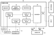
- FIG. 2 is a block diagram of a state determination unit according to the first embodiment of the present invention.
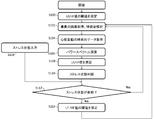
- 4 is a flowchart of a process of the operation control adjustment device of the first embodiment according to the present invention.
- FIG. 4 is a block diagram of an operation control adjustment device according to a second embodiment of the present invention.
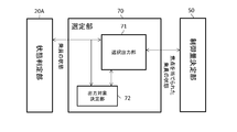
- FIG. 9 is a block diagram of a selection unit according to a second embodiment of the present invention.
- the driving control adjustment device 100 in the present embodiment will be described.
- the driving control adjustment device 100 is installed in the vehicle CR.
- the vehicle CR may be a passenger car such as a train or a train.
- a description will be given of an example of a car including a relatively small car having a capacity of several people to a large car such as a bus.
- it may be a small car, a privately owned car, or a car shared by a plurality of people, such as a share car.
- the vehicle CR includes a driving control system DC that performs driving support and automatic driving control of the vehicle CR.
- the operation control system DC includes many sensors in addition to sensors related to a main control system for acceleration, steering, and braking in order to perform driving support and automatic driving.
- vehicle sensors include an acceleration sensor, a vehicle speed sensor, a steering angle sensor, a vibration sensor, a yaw rate sensor, a gyroscope, an inter-vehicle distance sensor, a camera, a LIDAR, and a position sensor (GPS: Global). Positioning @ System), road sign sensors, in-vehicle networks, and the like, and acquire information such as target physical quantities from many information sources.
- the driving control system DC also includes a number of ECUs (Electronic Control Units) that actually perform driving support and automatic driving control (ECUs 1 to 3 in this figure).
- ECUs 1 to 3 Electronic Control Units
- those related to the main control system include an auto cruise ECU, an engine control ECU, a steering control ECU, a brake control ECU, and the like.
- Each ECU is provided with an actuator (actuators 1 to 3 in this figure) corresponding to a motor, a solenoid, and the like, which generates an operation.
- the engine control ECU corresponds to the engine
- the steering control ECU corresponds to the steering
- the brake control ECU corresponds to the brake.
- the steering control ECU controls steering as an actuator in accordance with a steering angle detected by a steering angle sensor that is one of vehicle sensors.
- the steering control ECU controls the steering so as not to deviate from the lane.
- the lane departure prevention support system which is considered as one of driving assistance, issues a warning to the driver when the vehicle CR is likely to deviate from the lane, and assists the driver in controlling the steering in response to the warning.
- the combination of the vehicle sensors 1-4, the ECUs 1-3, and the actuators 1-3 is not a fixed relationship but changes according to the level of automation and the state of the vehicle CR.
- the driving control adjustment device 100 is provided in the driving control system DC by being connected to the ECUs 1 to 3 and the vehicle sensors 1 to 4 via a communication bus such as CAN (Car Area Network).
- the driving control adjustment device 100 is used in a driving control system DC that executes at least one of driving support and automatic driving of the vehicle CR as described above.
- the operation control adjustment device 100 supports the operation control system DC so that the control amount when the operation control system DC controls the actuators 1 to 3 will be described later.
- the driving control adjustment device 100 includes a biological information acquisition unit 10, a state determination unit 20, a determination correction unit 30, a feedback reception unit 40, a control amount determination unit 50, and an output unit 60.
- the biological information acquisition unit 10 acquires information on a biological signal of a driver who is an occupant of the vehicle CR.
- the biological signal includes at least vital signs, reflection, and voluntary movement. Vital signs are proof of living as a living thing, reflex is an unconscious reaction of the living thing, and voluntary movement is movement and vocalization based on the will and intention of the living thing.
- Vital signs include blood pressure, pulse rate, respiratory rate, body temperature, sweating, brain waves, pupil reflex (light reflex), urinary bladder volume, arterial oxygen saturation (SpO 2 ), consciousness level (consciousness scale: GCS (Glasgow Coma) Scale), JCS (Japan Coma Scale), and the like.
- the reflection is a chemical reflection, a physical reflection, or an electric reflection.
- the chemical reflex is, for example, a reflex in which the respiratory rate decreases and the blood oxygen concentration (oxygen saturation) decreases.
- Physical reflexes are, for example, reflexes that close the eyelids when exposed to intense light in the eyes or that cause the muscles to be tense when the patella tendon is stimulated.
- the electrical reflex is, for example, a reaction in which a muscle responds and contracts when a low-frequency electrical stimulus is applied.
- the measuring device 10 (biological information acquisition unit 10) that measures these may be provided on a seat surface, a backrest, a headrest, an armrest, or the like of a seat on which a driver sits, and may directly or indirectly measure these.
- an imaging device that can irradiate the driver with electromagnetic waves having a wavelength of visible light / invisible light and capture an image of the reflected light may be used.
- a sphygmomanometer or the like that reads the movement of blood flow from reflected light of near-infrared light is used as the blood pressure sensor 11 (not shown).
- a millimeter wave radar, a vibration sensor, or the like is used as the heart rate sensor 11.
- respiration data a millimeter wave radar, a vibration sensor, or the like is used as the respiration sensor 11 (not shown).
- pulse wave data a millimeter wave radar, a vibration sensor, or the like is used as the pulse wave sensor 11 (not shown).
- a humidity sensor capactance
- an impedance sensor or the like is used as the perspiration sensor 11 (not shown).
- an imaging device equipped with thermography or the like is used as the body temperature sensor 11 (not shown).
- the camera 12 is used to acquire pupil and eyelid movement data. The camera 12 obtains eye movement data based on the size of the pupil, the number of blinks, the line of sight, and the like, and the occupant also obtains information such as the shaking of the head, the facial expression formed from the eyes / interline / lips / mouth corner, and the like.
- state data As state data.
- an audio microphone 11 is used.
- the voice microphone 11 can acquire data such as its timbre by capturing the frequency as a frequency, and can also acquire the meaning of utterance as data by combining voice recognition technology.
- a device using ultrasonic waves is used as the urinary bladder volume measurement sensor 11 (not shown).
- a pulse oximeter or the like is used to obtain arterial blood oxygen saturation data.
- a question may be asked from a speaker, and the response may be collected and detected.
- the steering torque sensor 13 is used to directly obtain the driver's tension state. Since the driver tends to squeeze the steering hard when nervous, the driver's nervous state is acquired by acquiring the operation reaction force detected by the steering torque sensor 13.
- These measuring devices 10 are merely examples, and the acquisition method is not particularly limited as long as the desired data can be acquired.
- the state determination unit 20 determines the state of the driver based on the biological information acquired by the biological information acquisition unit 10.
- the state determination unit 20 will be described with reference to FIG.
- the measuring device 10 will be described with a heart rate sensor 11 and a camera 12 as examples, and the vehicle sensors 1 to 4 will be described as examples with sensors that detect the steering angle and moment strength of the steering.
- the state determination unit 20 receives image data from the camera 12 and stores the image data.
- the image storage unit 21 extracts the image data stored in the image storage unit 21 and extracts a feature amount of the face image. And a feature amount analyzing unit 23 for analyzing the extracted feature amount.
- the state determination unit 20 further receives heart rate data from the heart rate sensor 11, stores the heart rate data storage unit 24, extracts the heart rate data stored in the heart rate data storage unit 24, and analyzes the heart rate data.
- An analysis unit 25 is provided.
- the state determination unit 20 further receives, from the steering torque sensor 13, a reaction force (operation reaction force) given by the driver to the steering during automatic steering, and stores the torque data in the torque data storage unit 26.
- a torque data analysis unit 27 that extracts torque data stored in the torque data storage unit 26 and analyzes the torque data.
- the state determination unit 20 further performs comprehensive analysis based on the analysis results performed by the feature amount analysis unit 23, the heart rate data analysis unit 25, and the torque data analysis unit 27 to determine the state of the driver.
- a determination unit 28 is provided.
- the image storage unit 21, the heartbeat data storage unit 24, and the torque data storage unit 26 are configured by a memory, and store the image data, the heartbeat data, and the torque data in time series.
- the face image feature value extraction unit 22 extracts a feature value of a face portion of the image data stored in the image storage unit 21.
- the face image feature amount extraction unit 22 extracts feature points around eyebrows and eyes, contour points, and nose and mouth from the face image.
- the feature analysis unit 23 analyzes the distance between the feature points extracted by the face image feature extraction unit 22 and the distribution of the feature of the pixel in the area surrounded by these feature points, and analyzes the attributes and facial expressions of the occupant. I do.
- the feature amount analysis unit 23 analyzes the change of the facial expression over time by comparing these feature points between two time points.
- the heart rate data analysis unit 25 extracts the heart rate data stored in the heart rate data storage unit 24, and analyzes the intervals and strengths of the heartbeats and their changes over time.
- the torque data analysis unit 27 extracts the torque data from the torque data storage unit 26 and, based on the reaction force (operation reaction force) given by the driver to the steering during automatic steering, calculates the steering angle and moment. Analyze the strength and their changes over time to estimate the driver's tension.
- the overall determination unit 28 includes a result of the feature value analysis of the face image performed by the feature value analysis unit 23, a result of the heart rate data analysis performed by the heart rate data analysis unit 25, an operation reaction force from the steering torque sensor 13, and a steering angle. Based on the data of the moment and the moment, the state of each occupant is determined by comprehensive analysis. For example, if a nervous expression can be read from a face image of a certain occupant, the heart rate is faster based on the heart rate data, and it is estimated that the user is nervous from the operation reaction force, the driver may be nervous. It is determined that it is in the state.
- the driver determines that the driver is nervous overall.
- the case where it is estimated that the user is nervous also from the operation reaction force means the case where the operation reaction force detected by the steering torque sensor 13 is equal to or more than a predetermined value. According to this, it is possible to accumulate highly-accurate preference data by detecting the tension state of the user from the steering operation that makes it easy to detect the state of the driver who is the user.
- the comprehensive determination unit 28 acquires these biological signals measured by the measuring device 10 for the driver and determines whether the driver is relaxing, satisfied, uncomfortable, or nervous. Determine whether you are excited, afraid, have a motor sickness, what your physical condition is, how much your consciousness is, etc. using thresholds (judgment criteria). Do.
- the above-described determination by the comprehensive determination unit 28 is an example, and comprehensively determines information obtained from various biological signals.
- the feedback receiving unit 40 receives feedback from the occupant who is the driver regarding the state determined by the state determining unit 20.
- the feedback receiving unit 40 is provided with an input device such as a touch panel, and may directly receive an input from the driver, or may have a short-range wireless function, and may receive a driver's input from a terminal device such as a smartphone. Is also good.
- the feedback receiving unit 40 may prompt the user to input a tension state (stress state) at the time of the most recent ride.
- the feedback receiving unit 40 may be configured to receive the presence / absence of tension (two levels) at the time of boarding, or may be configured to receive the feedback at three or more levels (for example, five levels).
- the feedback receiving unit 40 transmits to the determination correcting unit 30 feedback about the actual stress level from the occupant.
- the judgment correction unit 30 corrects the threshold (judgment criterion) of the state judgment unit 20 based on the feedback received by the feedback reception unit 40.
- the correction of the threshold value performed by the determination correction unit 30 will be described with reference to an example of heart rate data acquired by the heart rate sensor 11 as shown in FIGS.
- the heartbeat data analysis unit 25 extracts the time-series heartbeat data stored in the heartbeat data storage unit 24, analyzes the heartbeat interval and strength, and changes over time, and obtains the occupant (driving ) Is under stress.
- an LF / HF value is known as an index for calculating a stress state from time-series heart rate data (for example, described in http://hclab.sakura.ne.jp/stress_nervous_stressindex.html ⁇ ).
- HF is an abbreviation for high frequency (HiHFrequency) fluctuation component, and refers to a fluctuation wave originating from respiration having a period of about 3 to 4 seconds or a total amount of a power spectrum in a frequency domain thereof.
- LF is an abbreviation of low-frequency (Low ⁇ ⁇ Frequency) fluctuation component, and refers to a fluctuation wave called a Mayer wave originating from a blood pressure change in a cycle of about 10 seconds or a total amount of a power spectrum in a frequency domain thereof.
- the LF / HF value (the ratio between the LF component and the HF component) varies depending on the balance between the sympathetic nerve and the parasympathetic tone, and the magnitude of the HF fluctuation wave and the LF fluctuation wave in the heart rate data changes. It is an index for estimating the stress state from the heart rate data using this.
- the LF / HF value is calculated using, for example, the integral value of the intensity of the LF component region (from 0.05 Hz to 0.15 Hz) and the HF component region (from 0.15 Hz to 0.40 Hz) of the power spectrum. Is done.
- the heart rate data analysis unit 25 calculates such LF / HF values from time-series heart rate data, for example, and analyzes the stress state.
- the overall determination unit 28 determines that the threshold value of the LF / HF value is, for example, a reference value of less than 2.0 and a threshold value of 2.0 to less than 5.0.
- a stress state is determined by setting an initial value of “caution” and 5.0 or more as “caution required”.
- the general determination unit 28 determines that the occupant is in a stress state requiring caution.
- the state determination unit 20 transmits the threshold value, which is a criterion for performing the determination, and the determination result, to the determination correction unit 30.
- the determination correcting unit 30 determines whether the current determination criterion is valid based on the actual stress state received from the feedback reception unit 40, the determination result received from the state determination unit 20, and the LF / HF value threshold that is the determination criterion. Check for no. For example, the LF / HF value is 5.1, and according to the current determination criteria (initial value), it is determined that the stress state is “caution needed”. If the stress state indicates that no stress is felt, the determination correction unit 30 corrects the threshold (determination criterion) of the state determination unit 20 to a “reference value” of, for example, less than 5.5. Then, the determination correction unit 30 transmits the corrected threshold LF / HF value to the state determination unit 20.
- the overall determination unit 28 of the state determination unit 20 performs the determination based on the received new LF / HF value threshold as a determination criterion. In this way, by receiving feedback from the occupant and correcting the criterion for judging the occupant's condition based on the feedback, the driving control adjustment that enables the occupant to perform driving control in accordance with the stress state actually felt by the occupant is performed.
- An apparatus 100 can be provided.
- the state determination unit 20 determines a biological signal that matches the corrected determination criterion from the plurality of biological signals acquired by the biological information acquisition unit 10. You may choose.
- the correction of the threshold value of the LF / HF value is described using the heart rate data acquired by the heart rate sensor 11 as an example.
- the state determined from the operation reaction force detected by the steering torque sensor 13 is a stress state. If not, that is, if the stress matches the stress actually felt by the occupant, it is preferable to make a determination on the occupant based on the steering reaction force instead of the heartbeat data.
- the criterion is corrected, by selecting a biological signal that matches the corrected criterion, it is possible to perform driving control in accordance with the stress state actually felt by the individual occupant thereafter. it can.
- the output unit 60 outputs the stress state determined by the state determination unit 20 to the occupant who has acquired the biological signal.
- the output unit 60 may be provided with a display device such as a display and output directly to the driver, or may be displayed on a terminal device such as a smartphone via a short-range wireless function.
- the driver can recognize the level of the stress state displayed on the output unit 60.
- the feedback receiving unit 40 receives feedback performed by the driver on the state output by the output unit 60. Without the output unit 60, the driver would input the stress state felt by the driver to the feedback receiving unit 40 as an absolute feeling, but the relative stress state compared to the determination result displayed by the output unit 60 Can be fed back, and the feedback becomes easy. In this way, by clearly indicating the determined state to the driver, the driver can perform feedback as compared with the stress state actually felt.
- the control amount determination unit 50 determines a control amount of operation control to be output to the operation control system DC based on the stress state determined by the state determination unit 20. That is, when the state determined by the state determination unit 20 is a bad state, the control amount determination unit 50 determines the control amount so as to make the state good.
- the bad state of the driver refers to a state where the level of the stress state obtained from the biological signal is at a level such as "attention required". To improve the driver's condition means to improve the level of such a stressed condition.
- the determination of the control amount of the operation control performed by the control amount determination unit 50 includes, for example, increasing / decreasing the inter-vehicle distance, changing the magnitude of acceleration / deceleration, and decreasing the magnitude of the acceleration in the traveling direction. / Increase the yaw rate, decrease / increase the magnitude of the vertical acceleration, and so on. For example, when the driver is feeling stress, the control amount determination unit 50 adjusts the value of the inter-vehicle distance, which is the control amount, to a value larger than the current value. Then, the adjusted control amount is output to the auto cruise ECU.
- the determined state is determined to be a correct state and the occupant's stress state is improved.
- appropriate operation control can be performed.
- FIG. 4 is a flowchart showing a process of the driving control and adjusting device 100 based on image data and heart rate data from the camera 12 and the heart rate sensor 11 as the measuring device 10.
- S in the flowchart means a step.
- the operation control and adjustment device 100 starts when driving assistance or automatic operation is set.
- the operation control adjustment device 100 sets a threshold value of the LF / HF value as a criterion for determining the stress state.
- This threshold value of the LF / HF value is an initial value if the threshold value has not been corrected in the past, and the threshold value of the LF / HF value most recently corrected if the threshold value has been corrected in the past.
- step S102 the state determination unit 20 (the image storage unit 21, the face image feature amount extraction unit 22, and the feature amount analysis unit 23) of the operation control adjustment device 100 acquires the occupant's face image via the camera 12, and The feature amount of the face image is extracted, and the extracted feature amount is analyzed. Subsequently, the heart rate data storage unit 24 of the state determination unit 20 acquires the fluctuation of the occupant's heart rate data via the heart rate sensor 11 as time-series data in S104. In step S106, the heart rate data analysis unit 25 of the state determination unit 20 calculates the total amount (integral value) of the power spectrum of HF (high frequency fluctuation component) and the total amount (integral value) of the power spectrum of LF (high frequency fluctuation component). Then, in S108, the ratio between the two is calculated, and the LF / HF value is calculated.
- HF high frequency fluctuation component
- LF high frequency fluctuation component
- step S110 the comprehensive determination unit 28 of the state determination unit 20 comprehensively determines the stress state from the stress state based on the feature amount of the face image and the stress state based on the LF / HF value.
- step S116 the feedback receiving unit 40 receives feedback on the actual stress state from the occupant who has acquired the face image and the heart rate data.
- step S112 the determination correction unit 30 checks whether the determined stress state matches the fed-back stress state. If they match, the state determination unit 20 determines that the determination criterion of the determined stress state is correct, and determines the stress state based on the determination criterion (S102 to S110 are repeated).
- the determination correction unit 30 corrects the threshold of the LF / HF value for determining the stress state or the threshold of the feature amount of the face image to match, and the corrected threshold (determination criterion) Is transmitted to the state determination unit 20. Then, from the next stress determination, the state determination unit 20 determines the stress state based on the corrected determination criterion (return to S102).
- the driving control adjustment method obtains the occupant's biological signal, determines the state of the occupant based on the obtained biological signal, receives feedback from the occupant on the determined state, and determines based on the feedback.
- This is an operation control adjustment method used in an operation control system for correcting a reference.
- the driving control adjustment that receives the feedback from the occupant and corrects the criterion for judging the state of the occupant based on the feedback, so that the driving control can be performed according to the stress actually felt by the occupant.
- a method can be provided.
- the operation control adjustment device 100A includes a biological information acquisition unit 10A, a state determination unit 20A, a determination correction unit 30, a feedback reception unit 40A, a control amount determination unit 50, an output unit 60, and a selection unit 70. .
- the biological information acquiring unit 10A acquires information on the biological signals of the occupants 1 to 3 of the vehicle CR including the driver as well as the driver.
- the measuring device 10A biological information acquisition unit 10A
- the measuring device 10A that measures biological information is provided on a seat surface, a backrest, a headrest, an armrest, or the like of a seat on which an occupant sits, and may be a device that can directly or indirectly measure these. Further, an imaging device that can irradiate an occupant with electromagnetic waves having a wavelength of visible light / invisible light and image the reflected light may be used.
- the measuring device 10A is installed in the seat, it is preferable that the measuring device 10A is installed not only in the driver's seat but also in each seat.
- the state determination unit 20A determines the state of each of the occupants 1 to 3 based on the biological information acquired by the biological information acquisition unit 10A. How to determine the state of each of the occupants 1 to 3 in the state determination unit 20A is as described above.
- the selection unit 70 selects the occupant to be focused on in determining the control amount of the main control system from the plurality of occupants 1 to 3 determined by the state determination unit 20A, and outputs the data.
- a crew member There are various ways to select a crew member. For example, an occupant in the worst state among the occupants 1 to 3 may be selected, or an occupant whose state such as the oldest or the youngest is likely to change may be selected.
- the worst state can be defined as a health state or a stress state obtained from a biological signal by a numerical value, and a bad state can be defined based on the absolute value or the magnitude of change. Since the age can be estimated from the face image captured by the camera 12, the occupant may be selected using the estimated age.
- the selection unit 70 includes a selection output unit 71 and an output target determination unit 72.
- the selection output unit 71 outputs past data and real-time data of a focused occupant. For example, it is the peak value of the heart rate data or data indicating the current state. If the selection output unit 71 outputs analog data, an analog switch or a multiplexer is used.
- the output target determination unit 72 determines the occupant to be focused on, and controls the selection output unit 71 to output data and status of the occupant. For example, when the worst occupant is determined, the selection output unit 71 is controlled so as to output the data and state of the occupant.
- the selecting unit 70 may select a plurality of occupants.
- the selecting unit 70 outputs data of the selected plurality of occupants and the like.
- the output target determination unit 72 controls the selection output unit 71 so as to output data and status of all the focused occupants.
- the control amount determination unit 50 determines the control amount of the operation control to be output to the operation control system DC based on the stress state of the occupant who focuses on the object determined by the state determination unit 20A. When a plurality of occupants are selected by the selection unit 70, the control amount determination unit 50 may determine the control amount so that at least the average of the states of all of the plurality of focused occupants does not deteriorate.
- the feedback receiving unit 40A receives feedback from the occupant selected and focused by the selecting unit 70 on the state determined by the state determining unit 20A. In this way, by receiving feedback from the selected occupant, it is possible to perform driving control in accordance with the stress state actually felt by the specific occupant.
- operation control adjustment device 10 measuring device (biological information acquisition unit) 11 sensor 12 camera (imaging device) Reference Signs List 20 state determination unit 21 image storage unit 22 face image feature amount extraction unit 23 feature amount analysis unit 24 heart rate data storage unit 25 heart rate data analysis unit 26 torque data storage unit 27 torque data analysis unit 28 first state determination unit 29 second state Judgment unit 30 Judgment correction unit 40 Feedback reception unit 50 Control amount determination unit 60 Output unit 70 Selection unit CR vehicle DC operation control system
Landscapes
- Engineering & Computer Science (AREA)
- Automation & Control Theory (AREA)
- Transportation (AREA)
- Mechanical Engineering (AREA)
- Physics & Mathematics (AREA)
- Human Computer Interaction (AREA)
- Mathematical Physics (AREA)
- General Physics & Mathematics (AREA)
- Control Of Driving Devices And Active Controlling Of Vehicle (AREA)
- Traffic Control Systems (AREA)
- Measurement Of The Respiration, Hearing Ability, Form, And Blood Characteristics Of Living Organisms (AREA)
Abstract
乗員個人の実際に感じたストレス状態に即した運転制御を行えるようにする。 車両CRの運転支援および自動運転の少なくとも一方の運転制御を実行する運転制御システムDCに用いられる運転制御調整装置100を提供する。運転制御調整装置100は、車両の乗員の生体信号を取得する生体情報取得部10と、生体情報取得部が取得した生体信号に基づき、乗員の状態を判定する状態判定部20と、状態判定部が判定した状態について、乗員からフィードバックを受け付けるフィードバック受付部40と、フィードバック受付部が受け付けたフィードバックに基づき、状態判定部の判定基準を修正する判定修正部30と、を備える。乗員のフィードバックに基づき乗員の状態を判定する判定基準を修正することで、乗員個人の実際に感じたストレスに即した運転制御を行える。
Description
本発明は、車両の自動運転などの運転制御を実行する運転制御システムに用いられる運転制御調整装置および運転制御調整方法に関する。
従来から、車両の自動運転や運転支援のシステムにおいて、乗員の生体情報などからストレスを判定し、その判定に基づき自動運転や運転支援を行う技術が提案されている。例えば、特許文献1は、運転者が危険を察知していない場合であっても事故防止が可能な運転支援装置を開示する。この運転支援装置は、運転者以外の搭乗者である同乗者の生体情報を取得する生体情報取得手段と、その生体情報に基づいて、同乗者の緊張度を判定する緊張度判定手段と、その緊張度に基づいて、運転操作に対する支援を行う運転操作支援手段と、を備える。
近年、自動運転や運転支援のシステムが車両に採用されてきており、今後乗員の生体情報を検出し、ストレスを判定し、その判定結果を自動運転等の制御に反映させる技術が、益々増加するものと考えられる。しかし、人が運転状況から受けるストレスの程度や、受けたストレスに対する生体情報への発現の程度は、個人差があり、システムが一律に判定することは難しい場合がある。
本発明は、かかる事情を鑑みて考案されたものであり、乗員個人の実際に感じたストレス状態に即した運転制御を行えるようにする運転制御調整装置および運転制御調整方法を提供するものである。
上記課題を解決するために、車両の運転支援および自動運転の少なくとも一方の運転制御を実行する運転制御システムに用いられる運転制御調整装置であって、車両の乗員の生体信号を取得する生体情報取得部と、生体情報取得部が取得した生体信号に基づき、乗員の状態を判定する状態判定部と、状態判定部が判定した状態について、乗員からフィードバックを受け付けるフィードバック受付部と、フィードバック受付部が受け付けたフィードバックに基づき、状態判定部の判定基準を修正する判定修正部と、を備える運転制御調整装置が提供される。
これによれば、乗員からフィードバックを受け付け、そのフィードバックに基づき乗員の状態を判定する判定基準を修正することで、乗員個人の実際に感じたストレス状態に即した運転制御を行えるようにする運転制御調整装置を提供することができる。
これによれば、乗員からフィードバックを受け付け、そのフィードバックに基づき乗員の状態を判定する判定基準を修正することで、乗員個人の実際に感じたストレス状態に即した運転制御を行えるようにする運転制御調整装置を提供することができる。
さらに、状態判定部は、判定修正部により判定基準が修正された場合、生体情報取得部が取得した複数の生体信号から、修正された判定基準に適合する生体信号を選択することを特徴としてもよい。
これによれば、判定基準が修正された場合、修正された判定基準に適合する生体信号を選択することで、以降乗員個人の実際に感じたストレス状態に即した運転制御を行えるようにすることができる。
これによれば、判定基準が修正された場合、修正された判定基準に適合する生体信号を選択することで、以降乗員個人の実際に感じたストレス状態に即した運転制御を行えるようにすることができる。
さらに、状態判定部が判定した状態に基づき、運転制御システムに出力する運転制御の制御量を決定する制御量決定部をさらに備え、制御量決定部は、状態判定部が判定した状態が悪い状態である場合に、良い状態にするように制御量を決定することを特徴としてもよい。
これによれば、判定した状態が悪い状態である場合には良い状態にするように制御量を決定することで、フィードバックを行った後には、判定した状態が正しい状態として乗員のストレス状態を改善させるように適切な運転制御を行えるようにすることができる。
これによれば、判定した状態が悪い状態である場合には良い状態にするように制御量を決定することで、フィードバックを行った後には、判定した状態が正しい状態として乗員のストレス状態を改善させるように適切な運転制御を行えるようにすることができる。
さらに、状態判定部が判定した状態を乗員に出力する出力部をさらに備え、フィードバック受付部は、出力部が出力した状態に対して乗員が行うフィードバックを受け付けることを特徴としてもよい。
これによれば、乗員に対して判定した状態を明示することで、乗員は、実際に感じたストレス状態と比較して、フィードバックを行うことができる。
これによれば、乗員に対して判定した状態を明示することで、乗員は、実際に感じたストレス状態と比較して、フィードバックを行うことができる。
さらに、複数の乗員の中から選定する選定部をさらに備え、生体情報取得部は、複数の乗員の生体信号を取得し、状態判定部は、複数の乗員の状態を判定し、フィードバック受付部は、選定部によって選定された乗員からフィードバックを受け付けることを特徴としてもよい。
これによれば、選定された乗員からフィードバックを受け付けることで、特定の乗員の実際に感じたストレス状態に即した運転制御を行うことができる。
これによれば、選定された乗員からフィードバックを受け付けることで、特定の乗員の実際に感じたストレス状態に即した運転制御を行うことができる。
上記課題を解決するために、車両の運転支援および自動運転の少なくとも一方の運転制御を実行する運転制御システムに用いられる運転制御調整方法であって、車両の乗員の生体信号を取得し、取得した生体信号に基づき乗員の状態を判定し、判定した状態について、乗員からフィードバックを受け付け、フィードバックに基づき判定基準を修正する、運転制御調整方法が提供される。
これによれば、乗員からフィードバックを受け付け、そのフィードバックに基づき乗員の状態を判定する判定基準を修正することで、乗員個人の実際に感じたストレスに即した運転制御を行えるようにする運転制御調整方法を提供することができる。
これによれば、乗員からフィードバックを受け付け、そのフィードバックに基づき乗員の状態を判定する判定基準を修正することで、乗員個人の実際に感じたストレスに即した運転制御を行えるようにする運転制御調整方法を提供することができる。
以上説明したように、本発明によれば、乗員個人の実際に感じたストレスに即した運転制御を行えるようにする運転制御調整装置および運転制御調整方法を提供することができる。
以下では、図面を参照しながら、本発明に係る各実施例について説明する。
<第一実施例>
図1と図2を参照し、本実施例における運転制御調整装置100を説明する。運転制御調整装置100は、車両CRに設置される。車両CRは、電車や列車などの客車であってもよいが、本実施例では、数人の乗車定員の比較的小型車からバスなどの大型車を含む自動車を例に説明する。また、小型車であっても、個人所有の車であってもよいし、シェアカーのように複数の人が共有する車であってもよい。
図1と図2を参照し、本実施例における運転制御調整装置100を説明する。運転制御調整装置100は、車両CRに設置される。車両CRは、電車や列車などの客車であってもよいが、本実施例では、数人の乗車定員の比較的小型車からバスなどの大型車を含む自動車を例に説明する。また、小型車であっても、個人所有の車であってもよいし、シェアカーのように複数の人が共有する車であってもよい。
車両CRは、車両CRの運転支援や自動運転の制御を行う運転制御システムDCを備える。運転制御システムDCは、運転支援や自動運転を行うために、加速・操舵・制動の主制御系統に関連するセンサだけでなく、多数のセンサを備えている。たとえば、車両のセンサ(本図では車両センサ1~4)は、加速度センサ、車速センサ、操舵角センサ、振動センサ、ヨーレートセンサ、ジャイロスコープ、車間距離センサ、カメラ、LIDAR、位置センサ(GPS:Global Positioning System)、道路標識センサ、車載ネットワークなどであり、多数の情報源から目的とする物理量などの情報を取得する。
また、運転制御システムDCは、実際に運転支援や自動運転の制御を行う多数のECU(Electronic Control Unit)を備える(本図ではECU1~3)。たとえば、主制御系統に関連するものとして、オートクルーズECU、エンジン制御ECU、ステアリング制御ECU、ブレーキ制御ECUなどがある。それぞれのECUには、モータやソレノイドなどから構成され、動作を発生させるアクチュエータ(本図ではアクチュエータ1~3)が対応して備えられている。たとえば、エンジン制御ECUにはエンジン、ステアリング制御ECUにはステアリング、ブレーキ制御ECUにはブレーキが対応している。たとえば、ステアリング制御ECUは、車両センサの一つである操舵角センサが検出した操舵角などに応じて、アクチュエータとしてのステアリングを制御する。
なお、運転支援や自動運転の自動化レベルは様々な態様があり、それに応じて、ECUとアクチュエータの組み合わせも様々に考えられる。たとえば、自動運転の一つと考えられる自動車線維持支援システムでは、車両CRが車線を逸脱しそうな場合にステアリング制御ECUはステアリングを車線から逸脱しないように制御する。一方、運転支援の一つと考えられる車線逸脱防止支援システムでは、車両CRが車線を逸脱しそうな場合に運転者に警告を発し、その警告に対応して運転者がステアリングを制御することを支援する。車両センサ1~4、ECU1~3、およびアクチュエータ1~3の組み合わせは、固定的な関係ではなく、自動化のレベルや車両CRの状態に応じ変化するものである。
運転制御調整装置100は、運転制御システムDC内に、ECU1~3や車両センサ1~4と、CAN(Car Area Network)などの通信バスを介して接続されて備えられる。運転制御調整装置100は、上述したような車両CRの運転支援および自動運転の少なくとも一方の運転制御を実行する運転制御システムDCに用いられる。運転制御調整装置100は、運転制御システムDCがアクチュエータ1~3の制御を行う際の制御量を後述するように運転制御システムDCを支援するものである。
運転制御調整装置100は、生体情報取得部10と、状態判定部20と、判定修正部30と、フィードバック受付部40と、制御量決定部50と、出力部60とを備える。生体情報取得部10は、車両CRの乗員である運転者の生体信号の情報を取得する。生体信号は、バイタルサイン、反射、随意運動を少なくとも含むものとする。バイタルサインとは、生物として生きている証拠であり、反射とは、生物の無意識の反応であり、随意運動とは、生物の意志や意図に基づく運動や発声である。
バイタルサインは、血圧、脈拍数、呼吸速度、体温、発汗、脳波、瞳孔反射(対光反射)、膀胱内尿量、動脈血酸素飽和度(SpO2)、意識レベル(意識スケール:GCS(Glasgow Coma Scale)やJCS(Japan Coma Scale)等)などである。反射は、化学的反射、物理的反射、電気的反射である。化学的反射は、たとえば、呼吸数が減少し血中酸素濃度(酸素飽和度)が下がるような反射である。物理的反射は、たとえば、目に強い光を受けると瞼を閉じたり、膝蓋腱が刺激を受けると筋が緊張するような反射である。電気的反射は、たとえば、低周波の電気刺激を与えると筋肉が反応して収縮するような反応である。
これらを測る測定器10(生体情報取得部10)は、運転者が座る座席の座面、背もたれ、ヘッドレスト、肘掛けなどに設けられ、直接的または間接的にこれらを測定できるものであってもよいし、運転者に可視光/非可視光の波長の電磁波を照射し、その反射光を撮像することのできる撮像装置であってもよい。
たとえば、血圧のデータを取得するには、血圧センサ11(図示せず)として、近赤外光の反射光から血流の動きを読み取る血圧計等が用いられる。心拍のデータを取得するには、心拍センサ11として、ミリ波レーダや振動センサ等が用いられる。呼吸のデータを取得するには、呼吸センサ11(図示せず)として、ミリ波レーダや振動センサ等が用いられる。脈波のデータを取得するには、脈波センサ11(図示せず)として、ミリ波レーダや振動センサ等が用いられる。発汗のデータを取得するには、発汗センサ11(図示せず)として、湿度センサ(静電容量)やインピーダンスセンサ等が用いられる。体温のデータを取得するには、体温センサ11(図示せず)として、サーモグラフィを備えた撮像装置等が用いられる。瞳孔やまぶたの動きのデータを取得するには、カメラ12が用いられる。カメラ12は、瞳孔の大きさ、瞬目の回数、視線などにより、目の動きのデータを取得すると共に、頭の揺れ、目/眉間/唇/口角などから形成される表情、顔色なども乗員の状態のデータとして取得する。音声のデータを取得するには、音声マイク11(図示せず)が用いられる。音声マイク11は、周波数として捉えて、その声色等のデータを取得できると共に、音声認識技術を組み合わせて、発声したことの意味をデータとして取得することもできる。膀胱内尿量のデータを取得するには、膀胱内尿量測定センサ11(図示せず)として、超音波を使った機器が用いられる。動脈血酸素飽和度のデータを取得するには、パルスオキシメータ等が用いられる。意識レベルのデータを取得するには、スピーカから問いかけをして、その反応を集音して検出してもよい。運転者の緊張状態を直接的に取得すると考えられるものとして、ステアリングトルクセンサ13が用いられる。運転者は緊張するとステアリングを硬く握りしめる傾向にあるため、ステアリングトルクセンサ13が検出した操作反力を取得することで、運転者の緊張状態を取得する。これらの測定器10は、あくまで例であり、目的とするデータを取得できれば、その取得方法はとくに限定されない。
状態判定部20は、生体情報取得部10が取得した生体情報に基づいて、運転者の状態を判定する。図3を参照して、状態判定部20を説明する。なお、備える測定器10は、心拍センサ11とカメラ12を例として、また車両センサ1~4はステアリングの操舵角やモーメントの強さを検出するセンサを例として説明する。
状態判定部20は、カメラ12から画像データを受信し、記憶する画像記憶部21と、画像記憶部21が記憶する画像データを取り出し、顔画像の特徴量を抽出する顔画像特徴量抽出部22と、抽出した特徴量を解析する特徴量解析部23とを備える。また、状態判定部20は、さらに、心拍センサ11から心拍データを受信し、記憶する心拍データ記憶部24と、心拍データ記憶部24が記憶する心拍データを取り出し、心拍データの解析を行う心拍データ解析部25とを備える。また、状態判定部20は、さらに、ステアリングトルクセンサ13から自動操舵を行っているときのステアリングに対して運転者が与える反力(操作反力)を受信し、記憶するトルクデータ記憶部26と、トルクデータ記憶部26が記憶するトルクデータを取り出し、トルクデータの解析を行うトルクデータ解析部27とを備える。また、状態判定部20は、さらに、特徴量解析部23、心拍データ解析部25、およびトルクデータ解析部27が行った解析結果に基づき、総合的に解析し、運転者の状態を判定する総合判定部28を備える。
画像記憶部21、心拍データ記憶部24、およびトルクデータ記憶部26は、メモリから構成され、画像データ、心拍データ、トルクデータを時系列的に記憶する。顔画像特徴量抽出部22は、画像記憶部21に記憶された画像データの顔の部分における特徴量を抽出する。たとえば、顔画像特徴量抽出部22は、顔画像から眉や目の端点や輪郭点、鼻と口の周囲の特徴点を抽出する。特徴量解析部23は、顔画像特徴量抽出部22が抽出した特徴点の間の距離や、これら特徴点で包囲される領域の画素の特徴の分布を解析し、乗員の属性や表情を解析する。また、特徴量解析部23は、2時点の間でこれらの特徴点を比較することで経時的な表情の変化を解析する。心拍データ解析部25は、心拍データ記憶部24で記憶されている心拍データを取り出し、心拍の間隔や強さ、およびその経時的な変化を解析する。トルクデータ解析部27は、トルクデータ記憶部26からトルクデータを取り出し、自動操舵を行っているときのステアリングに対して運転者が与える反力(操作反力)に基づき、その操舵角やモーメントの強さ、それらの経時的な変化を解析し、運転者の緊張状態を推定する。
総合判定部28は、特徴量解析部23が行った顔画像の特徴量解析の結果、心拍データ解析部25が行った心拍データの解析結果、およびステアリングトルクセンサ13からの操作反力、操舵角やモーメントのデータに基づき、総合的に解析して各乗員の状態を判定する。たとえば、ある乗員の顔画像から緊張している表情が読み取れ、心拍データからも心拍が速くなっており、操作反力からも緊張していると推定されるような場合、その運転者は、緊張状態にあると判定する。また、運転者は、顔画像からは緊張の表情とは読み取れないが、心拍データや操作反力からは緊張していると推定される場合には総合的に緊張していると判定する。なお、操作反力からも緊張していると推定されるような場合とは、ステアリングトルクセンサ13が検出した操作反力が所定値以上の場合をいう。これによれば、利用者である運転者の状態を検知し易いステアリング操作から利用者の緊張状態を検出することで、精度の高い嗜好データを蓄積することができる。
総合判定部28は、運転者について、測定器10によって測定されるこれらの生体信号を取得し、リラックスしているのか、満足しているのか、不快に思っているのか、緊張しているのか、興奮しているのか、恐れているのか、車酔いをしているのか、体調はどのような状態か、意識がどの程度はっきりしているのか等についてそれぞれ閾値(判定基準)を以って判定を行う。なお、上述した総合判定部28の判定は、一例であり、種々の生体信号から得られる情報を総合的に判定する。
フィードバック受付部40は、状態判定部20が判定した状態について、運転者である乗員からフィードバックを受け付ける。フィードバック受付部40は、タッチパネルのような入力装置を設け、運転者からの入力を直接受け付けてもよいし、近距離無線機能を有し、スマートフォンのような端末装置から運転者の入力を受け付けてもよい。フィードバック受付部40は、直近の乗車時の緊張状態(ストレス状態)を入力するように促してもよい。フィードバック受付部40は、乗車時の緊張状態の有無(2段階)で受け付けるように構成してもよいし、3段階以上(たとえば、5段階)のレベルで受け付けるように構成してもよい。フィードバック受付部40は、乗員からのストレス状態が実際にどのような程度であったかのフィードバックを、判定修正部30に伝達する。
判定修正部30は、フィードバック受付部40が受け付けたフィードバックに基づき、状態判定部20の閾値(判定基準)を修正する。判定修正部30が行う閾値の修正について、図2と図3に示すように、心拍センサ11が取得する心拍データを例に説明する。心拍データ解析部25は、心拍データ記憶部24で記憶されている時系列の心拍データを取り出し、心拍の間隔や強さ、およびその経時的な変化を解析し、心拍データを取得した乗員(運転者)がどのようなストレス状態にあるかを解析する。
時系列の心拍データからストレス状態を算出する指標として、たとえばLF/HF値が知られている(たとえば、http://hclab.sakura.ne.jp/stress_nervous_stressindex.html で解説されている)。HFとは、高周波(Hi Frequency)変動成分の略で、3~4秒程度の周期を持つ呼吸を源とする変動波、またはその周波数領域のパワースペクトルの合計量を言う。LFとは、低周波(Low Frequency)変動成分の略で、メイヤー波と呼ばれる約10秒周期の血圧変化を源とする変動波、またはその周波数領域のパワースペクトルの合計量を言う。LF/HF値(LF成分とHF成分の比)は、交感神経と副交感神経の緊張状態のバランスによって、心拍データへのHFの変動波とLFの変動波の現れる大きさが変わってくるため、これを利用して心拍データからストレス状態を推定する指標である。LF/HF値は、たとえば、パワースペクトルのLF成分の領域(0.05Hzから0.15Hzまで)、およびHF成分の領域(0.15Hzから0.40Hzまで)の強度の積分値を用いて算出される。心拍データ解析部25は、たとえば、時系列の心拍データからこのようなLF/HF値を算出し、ストレス状態を解析する。
総合判定部28は、心拍データ解析部25が算出したLF/HF値に基づき、LF/HF値の閾値として、たとえば、2.0未満が「基準値」、2.0以上5.0未満が「注意」、5.0以上が「要注意」と初期値を設定して、ストレス状態を判定する。総合判定部28は、心拍データ解析部25が算出したLF/HF値がたとえば5.0以上であった場合、その乗員は要注意のストレス状態であると判定する。状態判定部20は、判定を行った基準である閾値と、行った判定結果を判定修正部30に伝達する。
判定修正部30は、フィードバック受付部40から受け取った実際のストレス状態と、状態判定部20から受け取った判定結果とその判定基準であるLF/HF値の閾値に基づき、現在の判定基準が妥当か否かを検査する。たとえば、LF/HF値が5.1であり、現在の判定基準(初期値)によると「要注意」のストレス状態と判定された結果であったが、フィードバック受付部40から受けた乗員の実際のストレス状態は、ストレスを感じていないことを示すものであった場合、判定修正部30は、「基準値」をたとえば5.5未満に状態判定部20の閾値(判定基準)を修正する。そして、判定修正部30は、修正した閾値のLF/HF値を状態判定部20に伝達する。状態判定部20の総合判定部28は、受け取った新しいLF/HF値の閾値を判定基準として以降判定を行う。このように、乗員からフィードバックを受け付け、そのフィードバックに基づき乗員の状態を判定する判定基準を修正することで、乗員個人の実際に感じたストレス状態に即した運転制御を行えるようにする運転制御調整装置100を提供することができる。
また、判定修正部30により上述したように判定基準が修正された場合、状態判定部20は、生体情報取得部10が取得した複数の生体信号から、修正された判定基準に適合する生体信号を選択してもよい。上述した例では、心拍センサ11が取得する心拍データを例にLF/HF値の閾値を修正することを説明したが、たとえば、ステアリングトルクセンサ13が検出した操作反力から判定した状態がストレス状態ではない場合、すなわち乗員が実際に感じたストレスと一致している場合、この乗員に対しては心拍データではなくステアリングの操作反力に基づき、判定することが好ましい。このように、判定基準が修正された場合、修正された判定基準に適合する生体信号を選択することで、以降乗員個人の実際に感じたストレス状態に即した運転制御を行えるようにすることができる。
出力部60は、生体信号を取得した乗員に対して状態判定部20が判定したストレス状態を出力する。出力部60は、ディスプレイのような表示装置を設け、運転者に対して直接出力してもよいし、近距離無線機能を介して、スマートフォンのような端末装置に表示してもよい。運転者は、出力部60に表示されたストレス状態のレベルを認識でき、そうすると、フィードバック受付部40は、出力部60が出力した状態に対して運転者が行うフィードバックを受け付けることになる。出力部60がないと、運転者は自分が感じたストレス状態を絶対的な感覚としてフィードバック受付部40に入力することになるが、出力部60が表示する判定結果と比べた相対的なストレス状態をフィードバックすることができるようになり、フィードバックが容易になる。このように、運転者に対して判定した状態を明示することで、運転者は、実際に感じたストレス状態と比較して、フィードバックを行うことができる。
制御量決定部50は、状態判定部20が判定したストレス状態に基づき、運転制御システムDCに出力する運転制御の制御量を決定する。すなわち、制御量決定部50は、状態判定部20が判定した状態が悪い状態である場合に、良い状態にするように制御量を決定する。運転者の悪い状態とは、生体信号から得られるストレス状態のレベルとして「要注意」のようなレベルにある状態を言う。また、運転者の状態を良くするとは、そのようなストレス状態のレベルが改善する方向にすることである。
制御量決定部50が行う運転制御の制御量の決定とは、たとえば、車間距離を長くする/短くする、加速/減速の大きさを変更する、進行方向横方向の加速度の大きさを小さくする/大きくする、ヨーレートを大きくする/小さくする、上下方向の加速度の大きさを小さくする/大きくする、などである。たとえば、運転者がストレスを感じている場合、制御量決定部50は、制御量である車間距離の値を現在よりも大きい値に調整する。そして、この調整された制御量をオートクルーズECUに対して出力する。このように、判定した状態が悪い状態である場合には良い状態にするように制御量を決定することで、フィードバックを行った後には、判定した状態が正しい状態として乗員のストレス状態を改善させるように適切な運転制御を行えるようにすることができる。
<運転制御調整方法について>
上述したことは、車両の運転支援および自動運転の少なくとも一方の運転制御を実行する運転制御システムDCに用いられる運転制御調整方法でもある。以下に、図4を参照し、運転制御調整装置100における制御の方法(運転制御調整方法)について説明する。
上述したことは、車両の運転支援および自動運転の少なくとも一方の運転制御を実行する運転制御システムDCに用いられる運転制御調整方法でもある。以下に、図4を参照し、運転制御調整装置100における制御の方法(運転制御調整方法)について説明する。
図4は、測定器10であるカメラ12と心拍センサ11から画像データおよび心拍データに基づいた、運転制御調整装置100の処理を示すフローチャートである。なお、フローチャートにおけるSはステップを意味する。運転制御調整装置100は、運転支援または自動運転に設定されると開始する。運転制御調整装置100は、S100において、ストレス状態の判断基準となるLF/HF値の閾値を設定する。このLF/HF値の閾値は、過去に当閾値が修正されたことがなければ初期値であり、過去に修正されたことがあれば、直近に修正されたLF/HF値の閾値である。
運転制御調整装置100の状態判定部20(画像記憶部21、顔画像特徴量抽出部22、特徴量解析部23)は、S102において、カメラ12を介して乗員の顔画像を取得すると共に、その顔画像の特徴量を抽出し、抽出した特徴量を解析する。続いて、状態判定部20の心拍データ記憶部24は、S104において、心拍センサ11を介して乗員の心拍データの変動を時系列データとして取得する。状態判定部20の心拍データ解析部25は、S106において、HF(高周波変動成分)のパワースペクトルの合計量(積分値)とLF(高周波変動成分)のパワースペクトルの合計量(積分値)を算出し、S108において、両者の比を計算し、LF/HF値を算出する。
状態判定部20の総合判定部28は、S110において、顔画像の特徴量に基づくストレス状態およびLF/HF値に基づくストレス状態から、総合的にストレス状態を判定する。フィードバック受付部40は、S116において、顔画像や心拍データを取得した乗員から、実際のストレス状態についてのフィードバックを受け付ける。判定修正部30は、S112において、判定したストレス状態とフィードバックされたストレス状態とが合致しているか否かを検査する。合致していた場合には、状態判定部20は、判定したストレス状態の判断基準は正しかったとして、その判断基準によりストレス状態を判断する(S102~S110を繰り返す)。合致していなかった場合、判定修正部30は、S114において、ストレス状態を判断するLF/HF値の閾値や顔画像の特徴量の閾値を合致するように修正し、修正した閾値(判断基準)を状態判定部20に伝達する。そして、次回のストレス判定からは、状態判定部20は、修正された判断基準によりストレス状態を判断する(S102に戻る)。
上述したように、運転制御調整方法は、乗員の生体信号を取得し、取得した生体信号に基づき乗員の状態を判定し、その判定した状態について、その乗員からフィードバックを受け付け、そのフィードバックに基づき判定基準を修正する、運転制御システムに用いられる運転制御調整方法である。これによれば、乗員からフィードバックを受け付け、そのフィードバックに基づき乗員の状態を判定する判定基準を修正することで、乗員個人の実際に感じたストレスに即した運転制御を行えるようにする運転制御調整方法を提供することができる。
<第二実施例>
図5と図6を参照し、本実施例における運転制御調整装置100Aを説明する。なお、重複記載を避けるため、同じ構成要素には同じ符号を付して説明を省略し、上記実施例と異なる点を中心に説明する。運転制御調整装置100Aは、生体情報取得部10Aと、状態判定部20Aと、判定修正部30と、フィードバック受付部40Aと、制御量決定部50と、出力部60と、選定部70とを備える。
図5と図6を参照し、本実施例における運転制御調整装置100Aを説明する。なお、重複記載を避けるため、同じ構成要素には同じ符号を付して説明を省略し、上記実施例と異なる点を中心に説明する。運転制御調整装置100Aは、生体情報取得部10Aと、状態判定部20Aと、判定修正部30と、フィードバック受付部40Aと、制御量決定部50と、出力部60と、選定部70とを備える。
生体情報取得部10Aは、運転者だけでなく運転者を含めた、車両CRの複数の乗員1~3のそれぞれの生体信号の情報を取得する。生体情報を測る測定器10A(生体情報取得部10A)は、乗員が座る座席の座面、背もたれ、ヘッドレスト、肘掛けなどに設けられ、直接的または間接的にこれらを測定できるものであってもよいし、乗員に可視光/非可視光の波長の電磁波を照射し、その反射光を撮像することのできる撮像装置であってもよい。座席に測定器10Aを設置する場合は、測定器10Aは、運転席だけでなく、座席毎に設置されることが好ましい。
状態判定部20Aは、生体情報取得部10Aが取得した生体情報に基づいて、複数の乗員1~3のそれぞれの状態を判定する。状態判定部20Aにおける乗員1~3それぞれの状態の判定のしかたは上述した通りである。
選定部70は、状態判定部20Aが判定した複数の乗員1~3の中から主制御系統の制御量を決定するに当たり焦点を当てる乗員を選定し、そのデータを出力する。どのような乗員を選定するかは、様々な考え方があり得る。たとえば、乗員1~3の中で最も悪い状態の乗員を選定してもよいし、最高齢や最年少などの状態が変わりやすい乗員を選定してもよい。なお、最も悪い状態とは、生体信号から得られる健康状態やストレス状態などを数値化し、その絶対値や変化量の大小などから悪い状態を定義できる。また、年齢は、カメラ12で撮像した顔画像から年齢が推定できるのでその推定年齢を使用して、乗員を選択してもよい。
図6に示すように、選定部70は、選択出力部71と、出力対象決定部72と、を備える。選択出力部71は、焦点を当てる乗員の過去のデータやリアルタイムのデータを出力する。たとえば、心拍データのピーク値や現在の状態を示すデータである。選択出力部71は、アナログデータを出力するのであれば、アナログスイッチやマルチプレクサが用いられる。出力対象決定部72は、焦点を当てる乗員を決定し、その乗員のデータや状態を出力するように選択出力部71を制御する。たとえば、最悪状態の乗員が決定される場合には、その乗員のデータや状態を出力するように選択出力部71を制御する。なお、選定部70は、複数の乗員が選定してもよく、この場合(たとえば、乗員全員が選定された場合)、選定された複数の乗員等のデータ等を出力する。その場合出力対象決定部72は、焦点を当てられた乗員全員のデータや状態を出力するように選択出力部71を制御する。
制御量決定部50は、状態判定部20Aが判定した焦点を当てる乗員のストレス状態に基づき、運転制御システムDCに出力する運転制御の制御量を決定する。選定部70において複数の乗員が選定された場合、制御量決定部50は、当該複数の焦点を当てた乗員全員の状態の平均を少なくとも悪くしないように制御量を決定してもよい。フィードバック受付部40Aは、状態判定部20Aが判定した状態について、選定部70が選定し焦点が当てられた乗員からフィードバックを受け付ける。このように、選定された乗員からフィードバックを受け付けることで、特定の乗員の実際に感じたストレス状態に即した運転制御を行うことができる。
なお、本発明は、例示した実施例に限定するものではなく、特許請求の範囲の各項に記載された内容から逸脱しない範囲の構成による実施が可能である。すなわち、本発明は、主に特定の実施形態に関して特に図示され、かつ説明されているが、本発明の技術的思想および目的の範囲から逸脱することなく、以上述べた実施形態に対し、数量、その他の詳細な構成において、当業者が様々な変形を加えることができるものである。
100 運転制御調整装置
10 測定器(生体情報取得部)
11 センサ
12 カメラ(撮像装置)
20 状態判定部
21 画像記憶部
22 顔画像特徴量抽出部
23 特徴量解析部
24 心拍データ記憶部
25 心拍データ解析部
26 トルクデータ記憶部
27 トルクデータ解析部
28 第一状態判定部
29 第二状態判定部
30 判定修正部
40 フィードバック受付部
50 制御量決定部
60 出力部
70 選定部
CR 車両
DC 運転制御システム
10 測定器(生体情報取得部)
11 センサ
12 カメラ(撮像装置)
20 状態判定部
21 画像記憶部
22 顔画像特徴量抽出部
23 特徴量解析部
24 心拍データ記憶部
25 心拍データ解析部
26 トルクデータ記憶部
27 トルクデータ解析部
28 第一状態判定部
29 第二状態判定部
30 判定修正部
40 フィードバック受付部
50 制御量決定部
60 出力部
70 選定部
CR 車両
DC 運転制御システム
Claims (6)
- 車両の運転支援および自動運転の少なくとも一方の運転制御を実行する運転制御システムに用いられる運転制御調整装置であって、
前記車両の乗員の生体信号を取得する生体情報取得部と、
前記生体情報取得部が取得した生体信号に基づき、前記乗員の状態を判定する状態判定部と、
前記状態判定部が判定した状態について、前記乗員からフィードバックを受け付けるフィードバック受付部と、
前記フィードバック受付部が受け付けたフィードバックに基づき、前記状態判定部の判定基準を修正する判定修正部と、
を備える運転制御調整装置。 - 前記状態判定部は、前記判定修正部により前記判定基準が修正された場合、前記生体情報取得部が取得した複数の生体信号から、修正された前記判定基準に適合する生体信号を選択することを特徴とする請求項1に記載の運転制御調整装置。
- 前記状態判定部が判定した状態に基づき、前記運転制御システムに出力する運転制御の制御量を決定する制御量決定部をさらに備え、
前記制御量決定部は、前記状態判定部が判定した状態が悪い状態である場合に、良い状態にするように制御量を決定することを特徴とする請求項1または2に記載の運転制御調整装置。 - 前記状態判定部が判定した状態を前記乗員に出力する出力部をさらに備え、
前記フィードバック受付部は、前記出力部が出力した状態に対して前記乗員が行うフィードバックを受け付けることを特徴とする請求項1乃至3のいずれかに記載の運転制御調整装置。 - 複数の前記乗員の中から選定する選定部をさらに備え、
前記生体情報取得部は、前記複数の乗員の生体信号を取得し、
前記状態判定部は、前記複数の乗員の状態を判定し、
前記フィードバック受付部は、前記選定部によって選定された前記乗員からフィードバックを受け付けることを特徴とする請求項1乃至4のいずれかに記載の運転制御調整装置。 - 車両の運転支援および自動運転の少なくとも一方の運転制御を実行する運転制御システムに用いられる運転制御調整方法であって、
前記車両の乗員の生体信号を取得し、
取得した生体信号に基づき前記乗員の状態を判定し、
判定した状態について、前記乗員からフィードバックを受け付け、
前記フィードバックに基づき判定基準を修正する、
運転制御調整方法。
Applications Claiming Priority (2)
| Application Number | Priority Date | Filing Date | Title |
|---|---|---|---|
| JP2018-156592 | 2018-08-23 | ||
| JP2018156592A JP6648788B1 (ja) | 2018-08-23 | 2018-08-23 | 運転制御調整装置および運転制御調整方法 |
Publications (1)
| Publication Number | Publication Date |
|---|---|
| WO2020039995A1 true WO2020039995A1 (ja) | 2020-02-27 |
Family
ID=69568238
Family Applications (1)
| Application Number | Title | Priority Date | Filing Date |
|---|---|---|---|
| PCT/JP2019/031794 Ceased WO2020039995A1 (ja) | 2018-08-23 | 2019-08-13 | 運転制御調整装置および運転制御調整方法 |
Country Status (2)
| Country | Link |
|---|---|
| JP (1) | JP6648788B1 (ja) |
| WO (1) | WO2020039995A1 (ja) |
Cited By (2)
| Publication number | Priority date | Publication date | Assignee | Title |
|---|---|---|---|---|
| CN117445933A (zh) * | 2023-11-07 | 2024-01-26 | 阿尔特汽车技术股份有限公司 | 基于驾驶员健康状态的自动控制方法、系统及电子设备 |
| WO2026058451A1 (ja) * | 2024-09-16 | 2026-03-19 | 日本電気株式会社 | 情報処理装置、情報処理方法及び記録媒体 |
Families Citing this family (1)
| Publication number | Priority date | Publication date | Assignee | Title |
|---|---|---|---|---|
| KR102467013B1 (ko) * | 2020-11-24 | 2022-11-15 | 주식회사 오비고 | 자율주행 차량으로부터 획득된 운행 데이터 및 자율주행 차량의 탑승자로부터 획득된 피드백 데이터를 이용하여 자율주행 차량의 자율주행 네트워크를 학습할 수 있도록 지원하는 방법 및 장치 |
Citations (8)
| Publication number | Priority date | Publication date | Assignee | Title |
|---|---|---|---|---|
| JP2011039601A (ja) * | 2009-08-06 | 2011-02-24 | Nissan Motor Co Ltd | 覚醒度調整装置及び方法 |
| JP2016115356A (ja) * | 2014-12-12 | 2016-06-23 | ソニー株式会社 | 自動運転制御装置および自動運転制御方法、並びにプログラム |
| JP2016182242A (ja) * | 2015-03-26 | 2016-10-20 | パイオニア株式会社 | 眠気算出装置 |
| JP2016191602A (ja) * | 2015-03-31 | 2016-11-10 | パイオニア株式会社 | 経路探索装置 |
| JP2017204015A (ja) * | 2016-05-09 | 2017-11-16 | 株式会社東海理化電機製作所 | 運転支援装置 |
| JP2017213984A (ja) * | 2016-05-31 | 2017-12-07 | 株式会社東芝 | 自律制御システム、サーバ装置及び自律制御方法 |
| JP2018008575A (ja) * | 2016-07-12 | 2018-01-18 | 株式会社デンソー | 車両制御装置 |
| JP2018112663A (ja) * | 2017-01-12 | 2018-07-19 | アルパイン株式会社 | 表示システム、サーバ、電子装置および地図表示方法 |
Family Cites Families (1)
| Publication number | Priority date | Publication date | Assignee | Title |
|---|---|---|---|---|
| EP3347253A1 (en) * | 2015-09-08 | 2018-07-18 | Apple Inc. | Comfort profiles for autonomous vehicle |
-
2018
- 2018-08-23 JP JP2018156592A patent/JP6648788B1/ja not_active Expired - Fee Related
-
2019
- 2019-08-13 WO PCT/JP2019/031794 patent/WO2020039995A1/ja not_active Ceased
Patent Citations (8)
| Publication number | Priority date | Publication date | Assignee | Title |
|---|---|---|---|---|
| JP2011039601A (ja) * | 2009-08-06 | 2011-02-24 | Nissan Motor Co Ltd | 覚醒度調整装置及び方法 |
| JP2016115356A (ja) * | 2014-12-12 | 2016-06-23 | ソニー株式会社 | 自動運転制御装置および自動運転制御方法、並びにプログラム |
| JP2016182242A (ja) * | 2015-03-26 | 2016-10-20 | パイオニア株式会社 | 眠気算出装置 |
| JP2016191602A (ja) * | 2015-03-31 | 2016-11-10 | パイオニア株式会社 | 経路探索装置 |
| JP2017204015A (ja) * | 2016-05-09 | 2017-11-16 | 株式会社東海理化電機製作所 | 運転支援装置 |
| JP2017213984A (ja) * | 2016-05-31 | 2017-12-07 | 株式会社東芝 | 自律制御システム、サーバ装置及び自律制御方法 |
| JP2018008575A (ja) * | 2016-07-12 | 2018-01-18 | 株式会社デンソー | 車両制御装置 |
| JP2018112663A (ja) * | 2017-01-12 | 2018-07-19 | アルパイン株式会社 | 表示システム、サーバ、電子装置および地図表示方法 |
Cited By (2)
| Publication number | Priority date | Publication date | Assignee | Title |
|---|---|---|---|---|
| CN117445933A (zh) * | 2023-11-07 | 2024-01-26 | 阿尔特汽车技术股份有限公司 | 基于驾驶员健康状态的自动控制方法、系统及电子设备 |
| WO2026058451A1 (ja) * | 2024-09-16 | 2026-03-19 | 日本電気株式会社 | 情報処理装置、情報処理方法及び記録媒体 |
Also Published As
| Publication number | Publication date |
|---|---|
| JP2020030688A (ja) | 2020-02-27 |
| JP6648788B1 (ja) | 2020-02-14 |
Similar Documents
| Publication | Publication Date | Title |
|---|---|---|
| US10867218B2 (en) | Biometric sensor fusion to classify vehicle passenger state | |
| US20210009149A1 (en) | Distractedness sensing system | |
| EP3889740B1 (en) | Affective-cognitive load based digital assistant | |
| DE102018207069B4 (de) | Verfahren und Steuereinheit zum Betreiben eines autonomen Fahrzeugs | |
| EP3779921B1 (en) | Information processing device, moving apparatus, method, and program | |
| CN107554528B (zh) | 驾乘人员的疲劳等级检测方法及装置、存储介质、终端 | |
| JP6645543B1 (ja) | 運転制御調整装置および運転制御調整方法 | |
| JP4727688B2 (ja) | 覚醒度推定装置 | |
| CN102396009B (zh) | 注意力状态判定装置、方法 | |
| CN101296657B (zh) | 人的状态检测装置 | |
| CN113795416A (zh) | 用于预测并减轻由晕车引起的干扰的方法 | |
| JP7183782B2 (ja) | 感情推定装置、環境提供システム、車両、感情推定方法、および情報処理プログラム | |
| WO2011052245A1 (ja) | 刺激効果予測装置、睡眠深度予測装置、刺激効果予測方法及び車両制御装置 | |
| KR20170018696A (ko) | 감성 인식 차량 제어 장치, 시스템 및 방법 | |
| JP7080657B2 (ja) | 感情識別装置 | |
| JP6648788B1 (ja) | 運転制御調整装置および運転制御調整方法 | |
| US11383640B2 (en) | Techniques for automatically reducing annoyance levels of drivers when using driver monitoring systems | |
| JP2018008575A (ja) | 車両制御装置 | |
| US20230406203A1 (en) | Driver attention system | |
| CN117540161A (zh) | 眩晕等级评估方法、眩晕缓解方法、装置、设备及介质 | |
| JP2019101472A (ja) | 感情推定装置 | |
| WO2020039994A1 (ja) | カーシェアリングシステム、運転制御調整装置、および車両の嗜好適合化方法 | |
| US9820687B2 (en) | Method for determining drowsiness | |
| JP2009172292A (ja) | 人の状態推定装置 | |
| JP2008073450A (ja) | 人の状態推定装置及び人の状態推定方法 |
Legal Events
| Date | Code | Title | Description |
|---|---|---|---|
| 121 | Ep: the epo has been informed by wipo that ep was designated in this application |
Ref document number: 19851940 Country of ref document: EP Kind code of ref document: A1 |
|
| NENP | Non-entry into the national phase |
Ref country code: DE |
|
| 122 | Ep: pct application non-entry in european phase |
Ref document number: 19851940 Country of ref document: EP Kind code of ref document: A1 |