WO2020039949A1 - タッチパネル用入力装置 - Google Patents
タッチパネル用入力装置 Download PDFInfo
- Publication number
- WO2020039949A1 WO2020039949A1 PCT/JP2019/031287 JP2019031287W WO2020039949A1 WO 2020039949 A1 WO2020039949 A1 WO 2020039949A1 JP 2019031287 W JP2019031287 W JP 2019031287W WO 2020039949 A1 WO2020039949 A1 WO 2020039949A1
- Authority
- WO
- WIPO (PCT)
- Prior art keywords
- touch panel
- region
- magnetic sheet
- pole
- pole region
- Prior art date
Links
Images


Classifications
-
- G—PHYSICS
- G06—COMPUTING; CALCULATING OR COUNTING
- G06F—ELECTRIC DIGITAL DATA PROCESSING
- G06F3/00—Input arrangements for transferring data to be processed into a form capable of being handled by the computer; Output arrangements for transferring data from processing unit to output unit, e.g. interface arrangements
- G06F3/01—Input arrangements or combined input and output arrangements for interaction between user and computer
- G06F3/03—Arrangements for converting the position or the displacement of a member into a coded form
- G06F3/033—Pointing devices displaced or positioned by the user, e.g. mice, trackballs, pens or joysticks; Accessories therefor
- G06F3/039—Accessories therefor, e.g. mouse pads
- G06F3/0393—Accessories for touch pads or touch screens, e.g. mechanical guides added to touch screens for drawing straight lines, hard keys overlaying touch screens or touch pads
-
- G—PHYSICS
- G06—COMPUTING; CALCULATING OR COUNTING
- G06F—ELECTRIC DIGITAL DATA PROCESSING
- G06F3/00—Input arrangements for transferring data to be processed into a form capable of being handled by the computer; Output arrangements for transferring data from processing unit to output unit, e.g. interface arrangements
- G06F3/01—Input arrangements or combined input and output arrangements for interaction between user and computer
- G06F3/016—Input arrangements with force or tactile feedback as computer generated output to the user
-
- G—PHYSICS
- G06—COMPUTING; CALCULATING OR COUNTING
- G06F—ELECTRIC DIGITAL DATA PROCESSING
- G06F3/00—Input arrangements for transferring data to be processed into a form capable of being handled by the computer; Output arrangements for transferring data from processing unit to output unit, e.g. interface arrangements
- G06F3/01—Input arrangements or combined input and output arrangements for interaction between user and computer
- G06F3/03—Arrangements for converting the position or the displacement of a member into a coded form
- G06F3/033—Pointing devices displaced or positioned by the user, e.g. mice, trackballs, pens or joysticks; Accessories therefor
- G06F3/0354—Pointing devices displaced or positioned by the user, e.g. mice, trackballs, pens or joysticks; Accessories therefor with detection of 2D relative movements between the device, or an operating part thereof, and a plane or surface, e.g. 2D mice, trackballs, pens or pucks
- G06F3/03548—Sliders, in which the moving part moves in a plane
-
- G—PHYSICS
- G06—COMPUTING; CALCULATING OR COUNTING
- G06F—ELECTRIC DIGITAL DATA PROCESSING
- G06F3/00—Input arrangements for transferring data to be processed into a form capable of being handled by the computer; Output arrangements for transferring data from processing unit to output unit, e.g. interface arrangements
- G06F3/01—Input arrangements or combined input and output arrangements for interaction between user and computer
- G06F3/03—Arrangements for converting the position or the displacement of a member into a coded form
- G06F3/033—Pointing devices displaced or positioned by the user, e.g. mice, trackballs, pens or joysticks; Accessories therefor
- G06F3/0362—Pointing devices displaced or positioned by the user, e.g. mice, trackballs, pens or joysticks; Accessories therefor with detection of 1D translations or rotations of an operating part of the device, e.g. scroll wheels, sliders, knobs, rollers or belts
-
- G—PHYSICS
- G06—COMPUTING; CALCULATING OR COUNTING
- G06F—ELECTRIC DIGITAL DATA PROCESSING
- G06F3/00—Input arrangements for transferring data to be processed into a form capable of being handled by the computer; Output arrangements for transferring data from processing unit to output unit, e.g. interface arrangements
- G06F3/01—Input arrangements or combined input and output arrangements for interaction between user and computer
- G06F3/03—Arrangements for converting the position or the displacement of a member into a coded form
- G06F3/041—Digitisers, e.g. for touch screens or touch pads, characterised by the transducing means
-
- G—PHYSICS
- G06—COMPUTING; CALCULATING OR COUNTING
- G06F—ELECTRIC DIGITAL DATA PROCESSING
- G06F3/00—Input arrangements for transferring data to be processed into a form capable of being handled by the computer; Output arrangements for transferring data from processing unit to output unit, e.g. interface arrangements
- G06F3/01—Input arrangements or combined input and output arrangements for interaction between user and computer
- G06F3/048—Interaction techniques based on graphical user interfaces [GUI]
- G06F3/0484—Interaction techniques based on graphical user interfaces [GUI] for the control of specific functions or operations, e.g. selecting or manipulating an object, an image or a displayed text element, setting a parameter value or selecting a range
- G06F3/04847—Interaction techniques to control parameter settings, e.g. interaction with sliders or dials
-
- G—PHYSICS
- G06—COMPUTING; CALCULATING OR COUNTING
- G06F—ELECTRIC DIGITAL DATA PROCESSING
- G06F3/00—Input arrangements for transferring data to be processed into a form capable of being handled by the computer; Output arrangements for transferring data from processing unit to output unit, e.g. interface arrangements
- G06F3/01—Input arrangements or combined input and output arrangements for interaction between user and computer
- G06F3/048—Interaction techniques based on graphical user interfaces [GUI]
- G06F3/0487—Interaction techniques based on graphical user interfaces [GUI] using specific features provided by the input device, e.g. functions controlled by the rotation of a mouse with dual sensing arrangements, or of the nature of the input device, e.g. tap gestures based on pressure sensed by a digitiser
- G06F3/0488—Interaction techniques based on graphical user interfaces [GUI] using specific features provided by the input device, e.g. functions controlled by the rotation of a mouse with dual sensing arrangements, or of the nature of the input device, e.g. tap gestures based on pressure sensed by a digitiser using a touch-screen or digitiser, e.g. input of commands through traced gestures
- G06F3/04886—Interaction techniques based on graphical user interfaces [GUI] using specific features provided by the input device, e.g. functions controlled by the rotation of a mouse with dual sensing arrangements, or of the nature of the input device, e.g. tap gestures based on pressure sensed by a digitiser using a touch-screen or digitiser, e.g. input of commands through traced gestures by partitioning the display area of the touch-screen or the surface of the digitising tablet into independently controllable areas, e.g. virtual keyboards or menus
Definitions
- the present invention relates to a technique for performing input to a touch panel while presenting a sense of force.
- Patent Document 1 discloses a technique for feeding back a sense of force to an operator of a pen tablet as an input device.
- a force sensation is presented by a magnetic field generated using an electromagnet. Therefore, any force sensation can be presented, but a power supply for driving the electromagnet is required.
- Non-Patent Document 1 discloses that a magnetic sheet in which an S-pole region and an N-pole region are magnetized in a stripe pattern or a checker pattern in advance, and a S-pole region and an N-pole region in a stripe pattern or checker pattern are previously formed.
- a technique of presenting a force sensation without using an electromagnet by pressing and moving a person with a finger so as to be in contact with another magnetized magnetic sheet has been disclosed.
- one or both magnetic sheets have been disclosed. It is disclosed that different force senses can be presented by making the widths of the S-pole region and the N-pole region different in the magnetization pattern of (1).
- Patent Document 1 is a technique for presenting a force sense when an operator performs an input operation on the input device, but presents a force sense according to the brightness of the screen of the display device. Therefore, in the technology disclosed in Patent Document 1, the sense of force presented to the operator and the input by the operator are irrelevant. Although the technology disclosed in Non-Patent Document 1 is a technology for presenting a force sense to an operator, the technology disclosed in Non-Patent Document 1 does not assume an operation itself on an input device. An object of the present invention is to provide a relationship between a force sense to be presented and an input by an operator on a touch panel.
- a first texture including an S-pole region and an N-pole region is magnetized in advance on the first surface, and the first surface is arranged with the plate surface opposite to the first surface facing the input surface side of the touch panel.
- An input to the touch panel is performed using an input device for a touch panel, which is constituted by a conductive portion that forms a conductive pattern on the second surface, and has a second object that is operated by an operator who performs an input operation on the touch panel. .
- a relationship can be provided between the force sense to be presented and the input by the operator on the touch panel.
- FIG. 1A and 1B are diagrams illustrating a magnetized magnetic sheet.
- FIG. 2 is a diagram exemplifying an operation of presenting a feeling of unevenness by two magnetic sheets.
- FIG. 3 is a diagram exemplifying an operation of presenting a feeling of unevenness by two magnetic sheets.
- 4A to 4D are diagrams illustrating a magnetized magnetic sheet.
- 5A to 5C are diagrams illustrating an operation of presenting a feeling of unevenness by using two magnetic sheets.
- 6A to 6D are diagrams illustrating a magnetized magnetic sheet.
- 7A and 7B are diagrams illustrating a magnetized magnetic sheet.
- FIG. 8 is a diagram illustrating the input device according to the embodiment.
- FIG. 9 is a diagram illustrating the second object.
- FIG. 8 is a diagram illustrating the input device according to the embodiment.
- FIG. 10 is a diagram illustrating a second object.
- FIG. 11 is a diagram illustrating a second object.
- FIG. 12A is a diagram illustrating a magnetized magnetic sheet.
- 12B and 12C are diagrams illustrating the second object.
- 13A and 13B are diagrams illustrating a magnetized magnetic sheet.
- FIG. 13C is a conceptual diagram for illustrating a sense of unevenness.
- 14A and 14B are diagrams illustrating a magnetized dial-type magnetic sheet.
- FIG. 14C is a conceptual diagram for illustrating a sense of unevenness.
- FIG. 15 is a diagram illustrating an input device.
- FIG. 16 is a diagram illustrating a second object.
- FIG. 17 is a diagram illustrating a second object.
- 18A to 18C are diagrams illustrating a magnetic sheet supported by a mechanical structure.
- the force sense presentation disclosed in Non-Patent Document 1 used by the present invention will be described.
- unevenness also referred to as “unevenness”
- the haptic presentation disclosed in Non-Patent Document 1 has a “first object” and a “second object”.
- the “first object” includes a “first surface”, and a “first texture” including an S-pole region and an N-pole region is magnetized on the “first surface”.
- the “second object” includes a “second surface”, and a “second texture” including an S-pole region and an N-pole region is magnetized on the “second surface”.
- the operator (“the subject of the operation”), which is a human or an animal other than a human, touches at least one of the “first object” and the “second object” and “the first surface” and “the second surface”. Is changed or the operation of changing the relative positional relationship between the “first surface” and the “second surface” while keeping or contacting each other, and / or the “first surface” and the “second surface” By performing the operation of changing the relative positional relationship between the "" and "”, the “operator” perceives the unevenness. In other words, the “operator” touches at least one of the “first object” and the “second object”, and keeps the “first surface” and the “second surface” in contact with or close to each other.
- first texture and the “second texture” are regions in which regions magnetized to the S pole and regions magnetized to the N pole are alternately and periodically arranged.
- first texture and the “second texture” are formed by alternately and periodically arranged band-shaped regions magnetized on the S pole and band-shaped regions magnetized on the N pole.
- it may include a periodic substantially checkered area magnetized on the S pole and a periodic substantially checkered area magnetized on the N pole.
- the pattern of the “first texture” and the pattern of the “second texture” may be the same or different.
- the manner of change in the shear stress that the “operator” receives from at least one of the “first object” and the “second object” differs.
- the sense of unevenness perceived by the “operator” is also different.
- the “acting subject” is changed from at least one of the “first object” and the “second object”
- the manner in which the shear stress changes may be different. In this case, depending on which direction the relative positional relationship between the “first surface” and the “second surface” is changed, the sense of unevenness perceived by the “operator” also differs.
- the “first texture” and the “second texture” are formed by alternately and periodically disposing a tape-shaped region magnetized on the S pole and a tape-shaped region magnetized on the N pole.
- the “first surface” and the “second surface” are in contact with each other such that the longitudinal direction of the tape-shaped region of the “first texture” follows the longitudinal direction of the tape-shaped region of the “second texture”.
- performing an operation of changing the relative positional relationship between the “first surface” and the “second surface” while keeping the proximity, and / or performing the operation between the “first surface” and the “second surface” An operation of changing the relative positional relationship may be performed.
- the “operation subject” is “ The way of changing the shear stress received from at least one of the “first object” and the “second object” is different, and the perceived unevenness is also different.
- an operation of changing the relative positional relationship between the “first surface” and the “second surface” and / or changing the relative positional relationship between the “first surface” and the “second surface” is an operation in which the “subject” moves the “second object” to change the relative positional relationship between the “first surface” and the “second surface”.
- “changing the relative positional relationship between the first surface and the second surface” means, for example, sliding the “second surface” with respect to the “first surface”.
- the magnetic sheet 210 of FIG. 1A is a specific example of the “first object”, and the magnetic sheet 220 of FIG. 1B is a specific example of the “second object”.
- a texture including an S-pole region 211a and an N-pole region 211b is magnetized.
- a band-shaped (tape-shaped) region 211a magnetized to the S-pole and a band-shaped (tape-shaped) region 211b magnetized to the N-pole are alternately and periodically arranged.
- a texture (second texture) including an S pole region 221a and an N pole region 221b is magnetized on one surface (plate surface) 221 (second surface) of the magnetic sheet 220.
- band-shaped (tape-shaped) regions 221 a magnetized to the S-pole and band-shaped (tape-shaped) regions 221 b magnetized to the N-pole are alternately and periodically arranged.
- the width (pitch) of the region 211a in the short direction, the width (pitch) of the region 211b in the short direction, the width (pitch) of the region 221a in the short direction, and the width (pitch) of the region 221b in the short direction Pitch) is 2 mm.
- differences in the magnetic poles of the region 211a, the region 211b, the region 221a, and the region 221b are represented by differences in the graphic patterns.
- the region 211a, the region 211b, the region 221a, and the region 221b are not painted so as to be visually distinguishable. That is, these textures are magnetized patterns and are not visually distinct patterns (the same applies hereinafter).
- the magnetization of the magnetic sheets 210 and 220 is performed, for example, by the method disclosed in Non-Patent Document 1. However, the magnetization of the magnetic sheets 210 and 220 may be performed by other methods (the same applies hereinafter).
- the operator arranges the magnetic sheet 210 so that the surface 211 faces outward and the magnetic sheet 210 so that the surface 221 contacts the surface 211.
- 220 is arranged.
- the magnetic sheet 220 is stacked on the magnetic sheet 210 such that the longitudinal direction D1 of the regions 211a and 211b of the magnetic sheet 210 follows the longitudinal direction D2 of the regions 221a and 221b of the magnetic sheet 220.
- the magnetic sheet 220 is overlaid on the magnetic sheet 210 such that the longitudinal direction D1 is along the longitudinal direction D2 (in other words, the longitudinal direction D1 and the longitudinal direction D2 are substantially parallel to each other).
- the operator touches the other surface 222 of the magnetic sheet 220 superimposed on the magnetic sheet 210 with the finger 200 and keeps the surface 211 and the surface 221 in contact with each other or close to each other (substantially in contact with each other).
- the relative positional relationship between the surface 211 and the surface 221 is changed in the XA direction which is the short direction of the regions 211 a and 211 b of the magnetic sheet 210.
- the shear stress in the XA direction that the operator receives from the magnetic sheet 220 changes periodically.
- the operator perceives a sense of unevenness in a direction substantially perpendicular to the surface 221.
- FIGS. 4A and 4B are examples of magnetic sheets 230 and 250 having a different pitch from the magnetic sheet 210
- FIGS. 4C and 4D are examples of magnetic sheets 240 and 260 having a different pitch from the magnetic sheet 220.
- the magnetic sheets 230 and 250 are specific examples of the “first object”
- the magnetic sheets 240 and 260 are specific examples of the “second object”.
- On one surface 231 (first surface) of the magnetic sheet 230, a band-shaped region 231a magnetized on the S-pole and a band-shaped region 231b magnetized on the N-pole are alternately and periodically arranged. .
- a band-shaped region 241a magnetized on the S-pole and a band-shaped region 241b magnetized on the N-pole are alternately and periodically arranged.
- a band-shaped region 251a magnetized on the S-pole and a band-shaped region 251b magnetized on the N-pole are alternately and periodically arranged.
- a band-shaped region 261a magnetized on the S-pole and a band-shaped region 261b magnetized on the N-pole are alternately and periodically arranged.
- the width of the region 231a in the short direction, the width of the region 231b in the short direction, the width of the region 241a in the short direction, and the width of the region 241b in the short direction are all 4 mm.
- the width of the region 251a in the short direction, the width of the region 251b in the short direction, the width of the region 261a in the short direction, and the width of the region 261b in the short direction are all 8 mm.
- the operator needs the magnetic sheets 210 and 220, the surfaces 211 and 221 and the areas 211a, 211b, 221a and 221b. Are replaced with the magnetic sheets 230 and 240, the surfaces 231 and 241 and the regions 231a, 231b, 241a and 241b, and the surfaces 231 and 241 are kept in contact with or close to each other as in the case where the magnetic sheets 210 and 220 are used.
- the operator can use the magnetic sheets 210 and 220, the surfaces 211 and 221, the areas 211a and 211b, 221a, 221b are replaced with magnetic sheets 250, 260, surfaces 251, 261 and regions 251a, 251b, 261a, 261b, and surfaces 251 and 261 are brought into contact with or close to each other as in the case where magnetic sheets 210 and 220 are used. While keeping the state, the operation of changing the relative positional relationship between the surface 251 and the surface 261 and / or the operation of changing the relative positional relationship between the surface 251 and the surface 261 are performed. (FIG. 5C).
- any of the magnetic sheets 210, 230, and 250 is used as the “first object”, and any of the magnetic sheets 220, 240, and 260 is used as the “second object”.
- the pitch of the “second object” may be different.
- FIGS. 6A to 6D and FIGS. 7A and 7B show a periodic substantially checkered area (substantially checker) magnetized on the S pole and a periodic substantially checkered area polarized on the N pole.
- first object and a “second object”.
- the magnetic sheets 210 ', 230', and 250 'in FIGS. 6A, 6C, and 7A are specific examples of the "first object”
- the magnetic sheets 220', 240 ', and 260' in FIGS. 6B, 6D, and 7B Is a specific example of the “second object”.
- the approximate checkerboard pattern means a checkerboard pattern or a pattern similar to a checkerboard pattern. That is, the substantially checkered pattern of the present embodiment is a pattern (checkered pattern) in which squares (or rectangles) magnetized with S poles and squares (or rectangles) magnetized with N poles are alternately and periodically arranged. ) As well as a pattern in which a pattern similar to a square (or rectangle) with the south pole magnetized and a pattern similar to a square (or rectangle) with the north pole magnetized are alternately and periodically arranged. Including. Examples of a pattern similar to a square (or rectangle) are a pattern in which the corners of a square (or rectangle) are rounded, a circle, an ellipse, and the like.
- one surface 211 ′ (first surface) of the magnetic sheet 210 ′ (first object) has a square region 211 a ′ with a magnetized south pole and a rounded corner 211 N ′.
- a substantially checkered texture (first texture) in which poles are magnetized and a square area 211b ′ with rounded corners is periodically and alternately repeated is magnetized.
- one surface 221 ′ (second surface) of the magnetic sheet 220 ′ (second object) has a square region 221 a ′ with a magnetized S pole and a rounded corner 221 a ′.
- a substantially checkered texture in which the poles are magnetized and the square regions 221b 'with rounded corners are periodically and alternately repeated is magnetized.
- the pitch of the substantially checkered pattern magnetized on the magnetic sheets 210 'and 220' (the width of each pattern that is periodically and alternately repeated) is 2 mm.
- one surface 231 ′ (first surface) of the magnetic sheet 230 ′ (first object) includes a square region 231 a ′ having a magnetized S pole and a rounded corner, and N
- a substantially checkered texture (first texture) in which poles are magnetized and a square area 231b 'with rounded corners is periodically and alternately repeated is magnetized.
- one surface 241 ′ (second surface) of the magnetic sheet 240 ′ (second object) includes a square region 241 a ′ having a rounded corner with an S pole magnetized and an N region.
- a substantially checkerboard texture (second texture) in which poles are magnetized and a square area 241b ′ with rounded corners is periodically and alternately repeated is magnetized.
- the pitches of the substantially checkered patterns magnetized on the magnetic sheets 230 'and 240' are all 4 mm.
- one surface 251 ′ (first surface) of the magnetic sheet 250 ′ (first object) includes a square region 251 a ′ with a rounded corner with an S pole magnetized and an N region.
- a substantially checkerboard texture (first texture) in which poles are magnetized and a square area 251b ′ with rounded corners is periodically and alternately repeated is magnetized.
- one surface 261 ′ (second surface) of the magnetic sheet 260 ′ (second object) includes a square region 261 a ′ having a magnetized S pole and a rounded corner, and an N region.
- a substantially checkerboard texture (second texture) in which poles are magnetized and a square area 261b ′ with rounded corners is periodically and alternately repeated is magnetized.
- the pitches of the substantially checkered patterns magnetized on the magnetic sheets 250 'and 260' are all 6 mm.
- first object When the magnetic sheet on which the substantially checkered texture is magnetized is referred to as a “first object” and a “second object”, the operator can also use the “first surface” and the “first object” of the “first object”.
- An operation of changing the relative positional relationship between the “first surface” and the “second surface” is performed while the two surfaces are in contact with or close to each other, and / or the “first surface” and the “first surface” are changed. By performing an operation of changing the relative positional relationship between the two surfaces, the unevenness can be perceived.
- the pitch of the “first object” and the pitch of the “second object” may be the same or different.
- a magnetic sheet magnetized with a substantially checkered texture is referred to as a “first object”, and a magnetic sheet magnetized with a texture in which the above-described band-like regions are alternately repeated is referred to as a “second object”.
- a magnetic sheet magnetized with a texture in which the above-mentioned band-shaped regions are alternately repeated is referred to as a “first object”, and a magnetic sheet magnetized with a substantially checkerboard texture is referred to as a “second object”. Is also good.
- Non-Patent Document 1 the technique of Non-Patent Document 1 is combined with a touch panel, and a “force sense presentation” that presents an operator with a feeling of unevenness when inputting information to the touch panel will be described.
- the “force presentation object” of the present embodiment is a “first object” arranged on the input surface of the touch panel, and a “force object” that is worn, gripped, or supported by an operator (“operator”) performing an input operation on the touch panel.
- Second object “.
- the “first object” includes a “first surface”, and a “first texture” including an S-pole region and an N-pole region is previously magnetized on the “first surface”.
- the “second object” includes a “second surface”, and a “second texture” including an S-pole region and an N-pole region is previously magnetized on the “second surface”.
- the “first object” is, for example, a magnetic sheet arranged with one plate surface facing the input surface side of the touch panel, and the “first surface” is the other plate surface of the magnetic sheet.
- the “acting subject” that performs an input operation on the touch panel on which the “first object” is arranged on the input surface mounts, holds or supports the “second object”, and “the first surface” and “the second surface” Operation of changing the relative positional relationship between the “first surface” and the “second surface” while keeping or contacting each other, and / or the relative position between the first surface and the second surface By performing the operation of changing the positional relationship, the input operation on the touch panel is performed, and the “operator” feels a sense of unevenness.
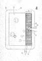
- FIG. 8 illustrates an example in which the technology of Non-Patent Document 1 is combined with a touch panel, and illustrates an example in which an input operation and a sense of force are displayed on the touch panel with respect to a displayed content such as a game.
- the above-described magnetic sheet 210 is attached to a lower part of an input surface (front surface) of a touch panel 401 ′ of an electronic device 400 ′ such as a smartphone terminal device or a tablet terminal device.
- One plate surface 212 of the magnetic sheet 210 is disposed toward the input surface side of the touch panel 401 ′, and the other plate surface 211 (first surface) of the magnetic sheet 210 has an S-pole region 211a and an N-pole region 211b.
- a first texture including the following is magnetized in advance.
- the magnetic sheet 220 described above is disposed on the plate surface 211 of the magnetic sheet 210.
- a texture including an S pole region 221a and an N pole region 221b is magnetized. They are arranged to face each other.
- the magnetic sheet 220 is stacked on the magnetic sheet 210 such that the longitudinal direction D1 of the regions 211a and 211b of the magnetic sheet 210 follows the longitudinal direction D2 of the regions 221a and 221b of the magnetic sheet 220.
- the operator touches the other surface 222 of the magnetic sheet 220 superimposed on the magnetic sheet 210 with the finger 200 and keeps the surface 211 and the surface 221 in contact with each other or close to each other (substantially in contact with each other).
- an input operation is performed on a content such as a game displayed on the touch panel 401 ′, and the operator perceives a sense of unevenness.
- the content of a content such as a game displayed on the touch panel 401 ′ (output device) changes, or the sound output from the speaker 402 ′ (output device) of the electronic device 400 ′ changes.
- the electronic device 400 ' is controlled as described above.
- FIG. 9 and 10 illustrate a “second object” according to the present modification.
- the “force sense presentation” of the present modification has M 2 “second objects”.
- m 2 1,..., M 2
- M 2 is an integer of 2 or more.
- Each “second object” 320-m 2 includes a magnetic sheet 220-m 2 and a conductive portion 323-m 2 on one surface 221-m 2 .
- a texture (second texture) including the S pole region 221a-m 2 and the N pole region 221b-m 2 is applied. Magnetized.
- "Second object” 320-m 2 as the surface 221-m 2 is opposed to the plate surface 211, i.e., the magnetic sheet 220-m 2 surface 221-m 2 and the conductive portion 323-m 2 Togaita It is arranged so as to face the surface 211.
- strip-shaped areas 221a-m 2 and 221b-m 2 extending in the direction D2 are provided on the surface 221-m 2 of the magnetic sheet 220-m 2 provided in the “second object” 320-m 2 . They are alternately and periodically arranged in a direction XB which is a direction substantially perpendicular to the direction D2.
- the second object 320-1, ..., the magnetic sheet 220-1 M 2 comprises, ..., magnetized pattern texture M 2 (second texture) are different from each other.
- the width of the region 221a-1 in the short direction (direction XB) and the width of the region 221b-1 in the short direction are all 3 mm, and the width of the region 221a-2 in the short direction is The width in the short direction of each of 221b-2 is 2 mm.
- “Second object” 320-1, ..., conductive portions 323-1 M 2 comprises, ..., conductive patterns of the M 2 are different from each other.
- the "second object” 320-1, ..., conductive portions 323-1 M 2 comprises, ..., a M 2, as the conductive patterns are different from one another, one or more electrical conductors are arranged .
- the conductive pattern of the conductive portion 323-1 is formed of two circular conductors having a diameter of 6 mm
- the conductive pattern of the conductive portion 323-2 is formed of one circular conductor having a diameter of 6 mm. Is done.
- the width of the region 211a of the surface 211 of the magnetic sheet 210 of the present modified example in the width direction is 2 mm.
- each “second object” 320-m 2 may be provided with nothing, or a display or mark that can identify which “second object” is attached. May be provided, a display or a mark for distinguishing the direction D2 or the direction XB may be attached, or a knob for the operator to operate may be provided.
- Figure 10 is an example in which the knob 324-m 2 on a surface 322-m 2 of the "second object" 320-m 2 in the example of FIG. 9.
- the knob 324-m 2 is a three-dimensional object having a shape that can be held by the operator with a plurality of fingers, and serves as a mark that can distinguish the direction D2 and the direction XB. Further, the knob 324-1 and the knob 324-2 are different in size, so that the knob 324-1 and the knob 324-2 can be used as marks for distinguishing which “second object”.
- the operator touches any of the “second objects” 320-m 2 superimposed on the magnetic sheet 210 with the finger 200, and touches the surface 221-m 2 and the conductive portion 323-m 2 with the plate surface 211.
- an operation of changing the relative positional relationship between the surface 221 -m 2 and the conductive portion 323 -m 2 and the plate surface 211 is performed while keeping them close (substantially in contact).
- the operator touches a portion of the “second object” that is not opposed to the 320-m 2 plate surface 211 with the finger 200 and, for example, contacts the 320-m 2 surface 322 -m of the “second object”.
- the operation may be performed in contact with 2 or the like.
- the operator may perform operation in contact with the knob 324-m 2 with a finger 200.
- the electronic device 400 ' the touch panel 401' to detect the position and the conductive pattern of contact or proximity to the conductive portion 323-m 2 to a detected position and a predetermined content for each detected conductive pattern on the touch panel 401 ' Input for the displayed content such as games. For example, in the case of a game content in which a bullet is fired at the position of the operator's finger on the touch panel 401 ′, the electronic device 400 ′ determines that the “second object” 320-2 has touched or approached the touch panel 401 ′. If this is detected, the game content is controlled so that a larger bullet is fired than when the “second object” 320-1 is used. As a result, the operator shoots a larger bullet while perceiving a greater sense of unevenness when using the “second object” 320-2 than when using the “second object” 320-1. In this manner, the input operation for the game content can be performed.
- FIG. 11 illustrates a “second object” of the present modification.
- the “second object” 500 includes a magnetic sheet 520 and a conductive portion 523 on one surface 521.
- a texture (second texture) including an S-pole region 521a and an N-pole region 521b is magnetized.
- the “second object” 520 is arranged such that the surface 521 faces the plate surface 211, that is, the surface 521 of the magnetic sheet 520 and the conductive portion 523 face the plate surface 211.
- a rectangular region in which the S pole is magnetized and a rectangular region in which the N pole is magnetized alternately and periodically. are located in
- the magnetization width in the D2A direction and the magnetization width in the D2B direction of the magnetic sheet 520 included in the “second object” 500 are different from each other.
- the short side (the width in the D2A direction) of each rectangular region is 2 mm
- the long side (the width in the D2B direction) is 3 mm.
- the conductive pattern in the D2A direction and the conductive pattern in the D2B direction of the conductive portion 523 included in the “second object” 500 are different from each other.
- a plurality of conductors are arranged in the conductive portion 523 included in the “second object” 500 such that the conductive pattern in the D2A direction and the conductive pattern in the D2B direction are different from each other.
- two circular conductors having a diameter of 6 mm are arranged in the conductive portion 523 at a center interval of 12 mm in the D2B direction.
- the width of the region 211a of the surface 211 of the magnetic sheet 210 of the present modified example in the width direction is 2 mm.
- the other surface 522 of the “second object” 500 may not have anything, may be provided with a display or mark capable of distinguishing the direction D2A or the direction D2B, or may be operated by the operator. May be provided.
- the operator touches the other surface 522 of the “second object” 500 superimposed on the magnetic sheet 210 with the finger 200, and aligns the surface 521, the conductive portion 523, and the plate surface 211 with each other so that the D2A direction and the D1 direction match. Or the relative positional relationship between the surface 521 and the conductive portion 523 and the plate surface 211 is changed while being in contact with or close to (substantially in contact with) each other so that the D2B direction and the D1 direction match.
- Perform the operation For example, the operator may perform an operation with the finger 200 in contact with a portion such as the surface 522 of the “second object” 500, that is, a portion of the “second object” 5000 not facing the plate surface 211. Further, for example, when the “second object” 500 is provided with a knob, the operator may perform an operation by touching the knob with the finger 200.
- the electronic device 400 ′ detects the position of the conductive part 523 in contact with or in proximity to the touch panel 401 ′ and the direction of the conductive pattern, and compares the detected position and the content determined in advance for each detected direction of the conductive pattern with the touch panel 401 ′. Is input for the content such as the game displayed in the. For example, in the case of a game content in which a bullet is fired at the position of the operator's finger on the touch panel 401 ', the electronic device 400' sets the "second object" 500 so that the D2B direction matches the D1 direction. When detecting that the second object 500 has contacted or approached the touch panel 401 ′, the D2A direction and the D1 direction coincide with each other. Control game content to fire large bullets.
- the operator uses the “second object” 500 so that the D2B direction and the D1 direction match
- the operator uses the “second object” 500 so that the D2A direction and the D1 direction match. It is possible to perform an input operation on the game content such that a large bullet is fired while perceiving a greater sense of unevenness as compared with the case where the player has made a game.
- a single "second object" can be used by changing its orientation, and the combination of the content of information input to the touch panel and the feeling of unevenness presented to the operator can be changed for each orientation of the "second object".
- Another example that differs from the first embodiment will be described as a third modification of the first embodiment, which is different from the first embodiment.
- FIGS. 12A to 12C show a magnetic sheet 610 of the present modification attached to a lower portion of an input surface (front surface) of a touch panel 401 ′ of an electronic device 400 ′ such as a smartphone terminal device or a tablet terminal device, and a magnetic sheet of the present modification.
- This is an example of a “second object” 600 of the present modification example arranged on a sheet 610.
- one plate surface 612 of the magnetic sheet 610 faces the input surface side of the touch panel 401 ′, and the arrow direction of D1B of the magnetic sheet 610 substantially matches the right direction of the input surface of the touch panel 401 ′.
- the magnetic sheet 610 is arranged such that the arrow direction of D1A of the magnetic sheet 610 substantially coincides with the upward direction of the input surface of the touch panel 401 ′ as viewed from the operator.
- a texture (first texture) including the S-pole region 611a and the N-pole region 611b is magnetized in advance on the other plate surface 611 (first surface) of the magnetic sheet 610.
- the S-pole region 611a and the N-pole region 611b have a V-shaped shape that is line-symmetric with a straight line in the D1B direction located at the center of the width of the plate surface 611 in the D1A direction. They are arranged periodically.
- the portion on the arrow direction side of D1A from the center of the width in the D1A direction is referred to as the S-pole partial region 611a1 and the N-pole partial region 611b1, and in the D1A direction.
- the portions on the opposite side to the arrow of D1A from the center of the width are referred to as the S pole partial region 611a2 and the N pole partial region 611b2
- the S pole partial region 611a1 and the N pole partial region 611b1 are short.
- a parallelogram whose side is the D1B direction, whose long side is ⁇ 45 degrees from the direction of the arrow D1B, and whose short side width (width in the D1B direction) is 4 mm, is a partial region 611a2 of the S pole and an N pole.
- the “second object” 600 includes a magnetic sheet 620 and a conductive portion 623 on one surface 621.
- the direction of the D2B arrow of the “second object” 600 substantially coincides with the right direction of the input surface of the touch panel 401 ′ such that the surface 621 faces the plate surface 611.
- the second object 600 is arranged such that the direction of the arrow D2A of the second object 600 substantially coincides with the upward direction of the input surface of the touch panel 401 'when viewed from the operator.
- the “second object” 600 is such that the surface 621 of the magnetic sheet 620 provided in the “second object” 600 and the conductive portion 623 face the plate surface 611, and the D2B of the “second object” 600
- the direction of the arrow substantially coincides with the direction of the arrow D1B of the magnetic sheet 610 attached to the input surface of the touch panel 401 ′, and the direction of the arrow D2A of the “second object” 600 and the magnetic direction attached to the input surface of the touch panel 401 ′.
- the sheet 610 is arranged so as to substantially coincide with the direction of the arrow D1A.
- a texture (second texture) including an S-pole region 621a and an N-pole region 621b is magnetized in advance on the surface 621 of the magnetic sheet 620 provided in the “second object” 600.
- the S-pole region 621a and the N-pole region 621b have a V-shape that is line-symmetric with a straight line in the D2B direction located at the center of the width of the plate surface 621 in the D2A direction. Are arranged alternately and periodically.
- each of the S-pole region 621a and the N-pole region 621b a portion on the arrow direction side of D2A from the center of the width in the D2A direction is referred to as an S-pole partial region 621a1 and an N-pole partial region 621b1, and a D2A direction.
- the portions on the opposite side to the arrow of D2A from the center of the width are referred to as the S pole partial region 621a2 and the N pole partial region 621b2
- the S pole partial region 621a1 and the N pole partial region 621b1 are short.
- a parallelogram whose side is the D2B direction, whose long side is ⁇ 45 degrees from the direction of the arrow D2B, and whose short side width (width in the D2B direction) is 4 mm, is a partial region 621a2 of the S pole and an N pole.
- the conductive part 623 included in the “second object” 600 includes a conductive pattern when viewed from the direction of the arrow D2A, a conductive pattern when viewed from the direction opposite to the arrow of D2A, and an arrow of D2B, as in the example of FIG. 12B.
- the conductors are arranged such that the conductive pattern when viewed from the direction and the conductive pattern when viewed from the direction opposite to the arrow of D2B are different from each other.
- three circular conductors having a diameter of 6 mm are arranged at each vertex of an isosceles triangle that is not an equilateral triangle in the conductive portion 623.
- the other surface 622 of the “second object” 600 may be provided with nothing, may be provided with a display or mark that can identify the arrow direction of D2A or the direction D2B, or may be operated by the operator. May be provided.
- the knob be a three-dimensional object having a shape that can be held by a plurality of fingers by the operator and a shape that allows the direction of the arrow D2A to be distinguished, like the knob 624 in the example of FIG. 12C.
- the operator touches the knob 624 of the “second object” 600 with the finger 200, and keeps the surface 621 and the conductive portion 623 and the plate surface 611 in contact with or close to (almost in contact with) the surface 621 and the conductive portion 623.
- the operator sets the “second object” 600 so that the arrow method of D2A matches the arrow direction of D1A, the arrow direction of D2A matches the direction opposite to the arrow of D1A,
- the operation is performed by either matching the arrow method with the arrow direction of D1B or matching the arrow direction of D2A with the opposite direction of the arrow of D1B.
- the electronic device 400 ′ detects the position of the conductive portion 623 in contact with or in proximity to the touch panel 401 ′ and the direction of the conductive pattern, and compares the detected position and the content determined in advance for each detected direction of the conductive pattern with the touch panel 401 ′. Is input for the content such as the game displayed in the. For example, in the case of a game content in which a bullet is fired at the position of the operator's finger on the touch panel 401 ′, the electronic device 400 ′ sets the “second” so that the arrow directions of D2A and D1A match. If it is detected that the “two objects” 600 have touched or approached the touch panel 401 ′, the game content is controlled to fire a larger bullet than in other cases.
- Non-Patent Document 1 As in the first embodiment, also in this embodiment, the technology of Non-Patent Document 1 is applied to an input interface of a touch panel, and an operator is presented with a feeling of unevenness when inputting information to the touch panel.
- different operations are performed by the operator by changing the combination of the “first object” arranged on the input surface of the touch panel and the “second object” worn, held, or supported by the operator. Present a sense.
- the “force sense presentation” of the present embodiment includes a “first object” arranged on the input surface of the touch panel and a plurality of “first objects” mounted, grasped, or supported by an “acting subject” performing an input operation on the touch panel. 2 objects ".
- the “first object” includes a “first surface”, and a “first texture” including an S-pole region and an N-pole region is previously magnetized on the “first surface”.
- the “second object” includes a “second surface”, and a “second texture” including an S-pole region and an N-pole region is previously magnetized on the “second surface”.
- the magnetization pattern of the “second texture” differs for each “second object”. That is, the magnetization patterns of the “second objects” of the plurality of “second objects” are different from each other.
- the “operator” mounts, holds or supports a “selected object” selected from a plurality of “second objects”, and “first surface” and “first surface” of the “first object” arranged on the input surface.
- the input operation on the touch panel is performed, and the shearing stress that the “operator” receives from the “selected object” changes periodically, thereby perceiving the sense of unevenness.
- the maximum value of the shear stress and / or the period of the shear stress and the feeling of unevenness differ for each “selected object”.
- ⁇ Slider type> 13A and 13B illustrate a slider-type “force sense presentation object” of the present embodiment.
- the slider-type “force sense presentation” is, for example, an input for operating the volume (volume) of sound output from a speaker or the brightness of illumination by an operation of an operator sliding a slider (moving in a predetermined axial direction).
- the interface is, for example, an input interface used by an operator to set a parameter value that can be freely set within a range between a predetermined minimum value and a maximum value to a desired value.
- the “force sense presentation” of the present embodiment has one magnetic sheet 710 (first object) and M 2 magnetic sheets 720-m 2 (second object).
- m 2 1,..., M 2
- M 2 is an integer of 2 or more.
- a texture (first texture) including an S pole region 711a and an N pole region 711b is magnetized on one surface 711 (first surface) of the magnetic sheet 710.
- band-shaped regions 711a magnetized on the S pole and band-shaped regions 711b magnetized on the N pole are alternately and periodically arranged.
- band-shaped regions 711a and 711b extending in the direction D1 are alternately and repeatedly arranged in a direction XA substantially perpendicular to the direction D1.
- the width of the region 711a in the short direction (direction XA) and the width of the region 711b in the short direction are both 6 mm.
- a texture including an S pole region 721a-m 2 and an N pole region 721b-m 2 (second texture) ) Is magnetized.
- a band-shaped region 721a-m 2 magnetized to the S pole and a band-shaped region 721b-m 2 magnetized to the N pole are alternately and periodically arranged.
- strip-shaped regions 721a-m 2 and 721b-m 2 extending in the direction D2 are alternately arranged in a direction XB substantially perpendicular to the direction D2.
- the magnetic sheet 720-1, ..., magnetized pattern of texture of M 2 are different from each other.
- the width of the region 721a-1 in the short direction (direction XB) and the width of the region 721b-1 in the short direction are all 3 mm, and the width of the region 721a-2 in the short direction and the region 721b.
- the width of the region 721a-1 in the short direction is 6 mm, and the width of the region 721a-1 in the short direction is 6 mm.
- a magnetic sheet 710 as a “first object” is attached to an input surface of the touch panel 401 of the electronic device 400.
- the other surface 712 of the magnetic sheet 710 (the surface opposite to the surface 711) is arranged facing the input surface side of the touch panel 401.
- any position of the touch panel 401 of the electronic device 400 is determined as an area for receiving a slide input operation (input by a slide operation) (when determined by software or the like mounted on the electronic device 400)
- the electronic device 400 displays the area on the touch panel 401, the operator arranges the surface 712 of the magnetic sheet 710 in the area.
- the electronic device 400 may detect in which area of the touch panel 401 the magnetic sheet 710 is attached, and accept a slide input operation in the detected area.
- the surface 712 of the magnetic sheet 710 may be arranged in any area of the touch panel 401 that can accept a slide input operation.
- the operator may be able to specify in which area of the touch panel 401 a slide input operation is to be accepted (for example, by making an input on the touch panel 401 to specify this area).
- the electronic device 400 detects which area of the touch panel 401 is specified, and arranges the surface 712 of the magnetic sheet 710 in the specified area input by the operator.
- an input interface is used for an operation when an operator sets a parameter value of the electronic device 400 that can be set freely within a range between a predetermined minimum value and a maximum value to a desired value.
- a parameter value of the electronic device 400 that can be set freely within a range between a predetermined minimum value and a maximum value to a desired value.
- the area of the touch panel 401 that accepts a slide input operation is in the vertical direction, that is, when the direction XA of the magnetic sheet 710 is the vertical direction of the touch panel 401, for example, the lower end of the area that accepts the slide input operation is minimized. What is necessary is just to allocate to a value and to assign the upper end of the area
- the area of the touch panel 401 that accepts a slide input operation is in the vertical direction, that is, when the direction XA of the magnetic sheet 710 is the horizontal direction of the touch panel 401, for example, the left end of the area that accepts the slide input operation is minimized.
- a value may be assigned, and the right end of the area for receiving the slide input operation may be assigned to the maximum value.
- the operator selects one of the magnetic sheet 720-m 2, the surface 722-m 2 faces the outside of the magnetic sheet 720-m 2 chosen (selected object), a magnetic sheet to the surface 711 of the magnetic sheet 710 720-m surface 721-m 2 of 2 places the magnetic sheet 720-m 2 in contact.
- the area of the magnetic sheet 710 711a, in a direction longitudinal direction D1 of 711b is follow the longitudinal direction D2 of the magnetic sheet 720-m 2 areas 721a-m 2, 721b-m 2, the magnetic sheet 720-m 2 is the magnetic sheet 710.
- the operator touches the surface 722-m 2 of the magnetic sheet 720-m 2 superimposed on the magnetic sheet 710 with a finger, and keeps the surface 711 and the surface 721-m 2 in contact with or close to each other.
- An operation of changing the relative positional relationship between the image data and ⁇ m 2 is performed.
- the relative positional relationship between the surface 711 and the surface 721-m 2 is changed (slid) in the XA direction, which is the shorter direction of the regions 711a and 711b of the magnetic sheet 720-m 2 .
- the input operation on the touch panel 401 (the sliding input operation) is performed, the operator XA direction of shear stress changes periodically received from the magnetic sheet 720-m 2.
- the operator perceives the direction of unevenness feeling substantially orthogonal to the plane 721-m 2.
- the magnetization patterns of the regions 721a-m 2 and 721b-m 2 are different for each magnetic sheet 720-m 2 . Therefore, depending on the combination of the magnetic sheet 720-m 2 and the selected magnetic sheet 710, different maximum and / or period of shear stress shear stress operator receives from the magnetic sheet 720-m 2, the operator The perception of unevenness is also different.
- the magnetic sheet 710 even though the same, the operator perceives the different irregularities sense depending on the magnetic sheet 720-m 2 chosen. That is, the operator can perceive a different tactile simply by changing the magnetic sheet 720-m 2. For example, as illustrated in FIG.
- ⁇ Dial type> 14A and 14B illustrate a dial-type “force sense presentation” of the present embodiment.
- the dial-type “force sense presentation” is, for example, a sound arrival direction to the operator by simultaneously controlling the volume output from a plurality of speakers arranged around the operator by rotating the dial by the operator.
- the “force sense presentation” of the present embodiment includes one magnetic sheet 810 (first object) and M 2 magnetic sheets 720-m 2 (second object).
- m 2 1,..., M 2
- M 2 is an integer of 2 or more.
- the magnetic sheet 810 has a substantially disk shape.
- a texture including an S-pole region 811a and an N-pole region 811b is magnetized.
- regions 811a magnetized to the S pole and regions 811b magnetized to the N pole are alternately and periodically arranged.
- regions 811a and 811b are repeatedly arranged along a direction R1 around the central axis O1 of the magnetic sheet 810 (an axis substantially perpendicular to the surface 811).
- the length of the arc corresponding to each region 811a and the length of the arc corresponding to each region 811b are both 6 mm.
- the S-pole region 811a and the N-pole region 811b provided on the surface 811 are preferably fan-shaped regions centered on the central axis O1.
- a columnar magnet having a predetermined diameter for example, 2 mm
- magnetizes all the N pole regions 811b first then reverses the magnetic poles of the magnets and magnetizes all the S pole regions 811a.
- the area 811a of the S pole and the area 811b of the N pole which are not completely fan-shaped as shown in FIG. 14A are provided, it is sufficient to present a desired uneven feeling.
- Magnetic sheet 820-m 2 is also substantially disc-shaped.
- the diameter of the magnetic sheet 820-m 2 is substantially the same as the diameter of the magnetic sheet 810, for example.
- a texture (second texture) including an S pole region 821a-m 2 and an N pole region 821b-m 2 ) Is magnetized.
- the surface 821-m 2 of the present embodiment includes a region 821b-m 2 magnetized in the magnetized regions 821a-m 2 and N pole to the S pole are periodically arranged alternately. In the example of FIG.
- the length of the arc corresponding to each region 821a-2 and the length corresponding to each region 821b-2 are both 2 mm.
- the length of the arc corresponding to each region 821a-3 and the length corresponding to each region 821b-3 are both 6 mm.
- the S pole region 821a-m 2 and the N pole region 821b-m 2 provided on the surface 821-m 2 are also preferably fan-shaped regions centered on the central axis O2.
- a columnar magnet having a predetermined diameter first magnetizes all the N-pole regions 821b-m 2 , and then reverses the magnetic poles of the magnets to form S-pole regions 821a-m 2.
- a texture as illustrated in FIG. 14B is formed.
- the full area 821a-m 2 of S pole are not sector and region 821b-m 2 of the N pole as shown in FIG. 14B is provided, it is sufficient to provide the desired irregular feeling.
- a magnetic sheet 810 as a “first object” is attached to an input surface of the touch panel 401 of the electronic device 400.
- the other surface 812 of the magnetic sheet 810 (the surface opposite to the surface 811) is arranged toward the input surface side of the touch panel 401.
- the electronic device 400 displays the region on the touch panel 401 to perform an operation.
- the surface 812 of the magnetic sheet 810 is arranged in the area by the user.
- the electronic device 400 may detect in which area of the touch panel 401 the magnetic sheet 810 is attached, and accept a rotation input operation in the detected area.
- the surface 812 of the magnetic sheet 810 may be arranged in any area of the touch panel 401 that can receive a rotation input operation.
- the operator may be able to specify which area of the touch panel 401 accepts the rotation input operation.
- the electronic device 400 detects which area of the touch panel 401 is specified, and arranges the surface 812 of the magnetic sheet 810 in the specified area input by the operator.
- the upper side of the area of the touch panel 401 that receives the rotation input operation is set in the forward direction of the operator ( The rightward rotation angle with respect to the direction of the operator is assigned to 0 degrees, and the lower side of the area of the touch panel 401 that receives the rotation input operation is assigned to the rearward direction of the operator (the rightward rotation angle with respect to the direction of the operator is 180 degrees).
- the right side of the area of the touch panel 401 for receiving the rotation input operation is assigned to the right direction of the operator (90 degrees clockwise with respect to the direction of the operator), and the left side of the area of the touch panel 401 for receiving the rotation input operation is assigned to the operator. What is necessary is just to assign to the left direction (clockwise angle with respect to the direction of the operator is 270 degrees).
- the upper side of the area for accepting the rotation input operation of the touch panel 401 is assigned to the north direction, and the rotation input operation of the touch panel 401 is accepted.
- the lower side of the area may be assigned to the south direction
- the right side of the area for accepting the rotation input operation of the touch panel 401 may be assigned to the east direction
- the left side of the area for accepting the rotation input operation of the touch panel 401 may be assigned to the west direction.
- the operator selects one of the magnetic sheet 820-m 2, the surface 822-m 2 faces the outside of the magnetic sheet 820-m 2 chosen (selected object), a magnetic sheet to the surface 811 of the magnetic sheet 810 820-m surface 821-m 2 of 2 places the magnetic sheet 820-m 2 in contact.
- the magnetic sheet 820-m 2 is superimposed on the magnetic sheet 810.
- the operator touches the surface 822-m 2 of the magnetic sheet 820-m 2 superimposed on the magnetic sheet 810 with a finger, and keeps the surface 811 and the surface 821-m 2 in contact with or close to each other.
- An operation of changing the relative positional relationship between the image data and ⁇ m 2 is performed.
- the change in the direction around the axis R1, R2 of the relative positional relationship between the surface 811 and the surface 821-m 2 causes (rotation).
- the maximum value of the shear stress and / or the cycle of the shear stress that the operator receives from the magnetic sheet 820-m 2 is different.
- the perception of unevenness is also different.
- the magnetic sheet 810 even though the same, the operator perceives the different irregularities sense depending on the magnetic sheet 820-m 2 chosen. That is, the operator can perceive different tactile simply by changing the magnetic sheet 820-m 2. For example, as illustrated in FIG.
- the rotation input operation can be performed smoothly without perceiving a click feeling, and when the magnetic sheet 820-2 is selected, a perceived sensation at fine intervals (for example, a W-step undulation sensation) is perceived.
- the rotation input operation can be performed while perceiving the click feeling of the W-stage, and when the magnetic sheet 820-3 is selected, the sense of unevenness at a coarse interval (for example, the sense of unevenness at the W'-stage) is perceived.
- the same rotation input operation can be performed while perceiving the click feeling of the W ′ stage.
- the electronic device 400 can identify the “second object”, and the content of information input to the touch panel and the unevenness presented to the operator. May be different for each “second object”. This example will be described as Modification Example 1 of the second embodiment, and portions different from the second embodiment will be described.
- FIG. 16 illustrates a “second object” of the present slider-type modification.
- Each “second object” 700-m 2 includes a magnetic sheet 720-m 2 and a conductive portion 723-m 2 on one surface.
- a texture (second texture) including an S-pole region 721a-m 2 and an N-pole region 721b-m 2 is applied. It is magnetized, and the surface 721-m 2 of the magnetic sheet 720-m 2 and the conductive portion 723-m 2 are arranged so as to face the surface 711 of the magnetic sheet 710.
- the magnetic sheet 720-m 2 included in the “second object” 700-m 2 of the example of FIG. 16 is the same as the magnetic sheet 720-m 2 of FIG. 13B of the second embodiment.
- "Second object" 700-1, ..., conductive portions 723-1 M 2 comprises, ..., conductive patterns of the M 2 are different from each other.
- the conductive pattern of the conductive portion 723-1 is formed of one circular conductor having a diameter of 6 mm
- the conductive pattern of the conductive portion 723-2 is formed of two circular conductors having a diameter of 6 mm.
- the conductive pattern of the conductive portion 723-3 is composed of three circular conductors having a diameter of 6 mm.
- the electronic device 400 detects the position and the conductive pattern of the conductive portion 723-m 2 in contact with or in proximity to the touch panel 401, for a predetermined parameter for each detected conductive pattern, the parameter values a value corresponding to the detected position Set as For example, when the selected object is the “second object” 700-1, the volume of the sound output from the speaker is set as the parameter to be operated, and the value corresponding to the detected position is set as the volume value. In the case of the “second object” 700-2, the brightness of the illumination is set as the parameter of the operation target, and the value corresponding to the detected position is set as the value of the brightness. With this, it is possible to make a relationship between which of the plurality of types of predetermined parameters to set, that is, the content of information input to the touch panel and the force sense presented to the operator. .
- FIG. 17 illustrates a “second object” of this modification of the dial type.
- Each “second object” 800-m 2 includes a magnetic sheet 820-m 2 and a conductive portion 823-m 2 on one surface.
- a texture (second texture) including the S pole region 821a-m 2 and the N pole region 821b-m 2 is applied. It is magnetized, and the surface 821-m 2 of the magnetic sheet 820-m 2 and the conductive portion 823-m 2 are arranged so as to face the surface 811 of the magnetic sheet 810.
- Magnetic sheet 820-m 2 where "second object” is 800-m 2 comprising in the example of FIG. 17 is the same as the magnetic sheet 820-m 2 in FIG. 14B in the second embodiment.
- conductive portions 823-1 M 2 comprises, ..., conductive patterns of the M 2 are different from each other.
- the conductive pattern of the conductive portion 823-1 is composed of one circular conductor having a diameter of 6 mm disposed at the center and one circular conductor having a diameter of 6 mm disposed near the circumference.
- the conductive pattern of the conductive portion 823-2 includes one circular conductor having a diameter of 6 mm disposed at the center, one circular conductor having a diameter of 6 mm disposed near the circumference, and one near the center. And one circular conductor arranged at a position other than the vicinity of the circumference.
- the conductive pattern of the conductive portion 823-3 is composed of one circular conductor having a diameter of 6 mm disposed at the center, one circular conductor having a diameter of 6 mm disposed near the circumference, and And two circular conductors located at positions other than the vicinity of the circumference and at different distances from the center.
- the operator touches a portion of the “second object” 800-m 2 superimposed on the magnetic sheet 810 with a finger, which is not opposed to the surface 811, and contacts the surface 821-m 2 and the conductive portion 823-m 2 with the surface 811.
- a finger which is not opposed to the surface 811
- the electronic device 400 detects the position and the conductive pattern of the conductive portion 823-m 2 in contact with or in proximity to the touch panel 401, for a predetermined parameter for each detected conductive pattern, a value corresponding to the detected rotational position parameters Set as a value.
- the direction of arrival of the sound is set as the parameter to be operated, and the value corresponding to the detected position is set as the angle of the direction of arrival.
- the position of the illumination is set as the parameter of the operation target, and the value corresponding to the detected position is set as the angle of the position of the illumination.
- FIG. 11 An example of the “second object” of this modification is illustrated in FIG. 11 similarly to Modification 2 of the first embodiment. That is, the configuration of the “second object” of the present modification is the same as the “second object” of the second modification of the first embodiment.
- the operator touches a portion of the “second object” 500 laid on the magnetic sheet 710 that is not opposed to the surface 711 with a finger, and moves the surface 521 and the conductive portion 523 and the surface 711 in the D2A direction and the D1 direction.
- the electronic device 400 detects the position of the conductive part 523 in contact with or in proximity to the touch panel 401 and the direction of the conductive pattern, and sets a value corresponding to the detected position for a parameter predetermined for each detected direction of the conductive pattern as a parameter. Set as a value. For example, when the operator uses the “second object” 500 so that the D2B direction and the D1 direction match, the electronic device 400 detects the volume of the sound output from the speaker as the parameter to be operated, and detects the sound.
- the electronic device 400 sets the brightness of the illumination to As a parameter to be operated, a value corresponding to the detected position is set as a brightness value. Thereby, it is possible to make a relationship between which of the two types of predetermined parameters is set, that is, the content of information input to the touch panel and the force sense presented to the operator. .
- the magnetic sheet 610 of FIG. 12 may be used instead of the magnetic sheet 710 as the first object, and the “second object” 600 of FIG. 12 may be used as the second object.
- the magnetic sheet of the first object of the "sense presentation" may be a rail-shaped (band-shaped) magnetic sheet 1420
- the magnetic sheet of the second object may be a magnetic sheet 1420 provided with a groove 1420a.
- On one surface 1411 (first surface) of the magnetic sheet 1410 the above-described texture (first texture) including the S-pole region and the N-pole region is magnetized.
- the texture (second texture) including the S-pole region and the N-pole region as described above is magnetized on the bottom surface 1421 (second surface) inside the groove 1420a of the magnetic sheet 1420.
- the magnetic sheet 1410 is arranged on the input surface of the touch panel 401.
- the surface 1412 of the magnetic sheet 1410 is arranged facing the input surface side of the touch panel 401.
- Part of the magnetic sheet 1410 is disposed inside the groove 1420a of the magnetic sheet 1420.
- the magnetic sheet 1420 is arranged such that the surface 1422 of the magnetic sheet 1420 faces outward, and the surface 1421 of the magnetic sheet 1420 contacts or approaches the surface 1411 of the magnetic sheet 1410.
- the operator touches the surface 1422 of the magnetic sheet 1420 stacked on the magnetic sheet 1410, and changes the relative positional relationship between the surfaces 1411 and 1421 while keeping the surfaces 1411 and 1421 in contact with or close to each other. (Slide operation in XA direction) is performed. At this time, the magnetic sheet 1420 slides in the XA direction while being supported by the inner wall of the groove 1420a of the magnetic sheet 1420.
- a fastener for preventing the center positions of the first object and the second object from being shifted may be arranged.
- the touch panel input devices (for example, FIG. 8, FIG. 9 to FIG. 12, FIG. 16, FIG. 17) exemplified in Modifications 1 to 3 of the first embodiment and Modifications 1 and 2 of the third embodiment are described as “
- a “first texture” including an S-pole region and an N-pole region is magnetized in advance on the “first surface (for example, surface 211)”, and a plate surface (for example, opposite to the “first surface”) is provided.
- Surface 212 facing the input surface side of the “touch panel (eg, touch panel 401 ′)” and “first object (eg, magnetic sheet 210)” and “second surface (eg, surface 221-m)”.
- a second texture including an S-pole region and an N-pole region is magnetized in advance, and the “magnetic sheet () is arranged with the“ second surface ”facing the“ first surface ”.
- a magnetic sheet 220-m 2) " to form a" conductive pattern "in the" second surface "" conductive portion
- a 323-m 2) " is constituted by a""second object to be operated by an operator to perform an input operation on the touch panel" (e.g., "second object” 320-m 2) ", Having.
- the “second texture” of the “magnetic sheet” indicates that the “second surface” of the “second object” is in a certain direction (hereinafter, referred to as a “first direction”) (for example, the D2A direction; in the example of FIG. 12B, When viewed from the direction of the arrow D2A, a direction different from the “first direction” (hereinafter, referred to as a “second direction”) (for example, the direction D2B.
- first direction for example, the D2A direction
- a second direction a direction different from the “first direction”
- the S-pole region and the N-pole region are repeatedly arranged according to a specific “first line (for example, the D1A direction and / or the D1B direction)” included in the “first surface”.
- the “second texture” includes an S pole region and an N pole according to a specific “second line (for example, the D2A direction and / or the D2B direction)” included in the “second surface”.
- the polar region includes a second repeating region in which the polar regions are repeatedly arranged, and the “second object” is the same as the “first line” of the “first object” and the “second line” of the “second object” Alternatively, it is arranged in one of an approximate arrangement and another arrangement.
- the touch panel input device outputs “a second object (for example, a second object 700-m 2 )”.
- the arrangement patterns of the S-pole region and the N-pole region of the “second texture” are different from each other, and “the conductive portion (for example, the conductive portion 723- m 2 ) ”are different from each other.
- the “first texture” is a first repetition in which an S-pole region and an N-pole region are repeatedly arranged according to a specific “first line (for example, the XA direction)” included in the “first surface”.
- the second texture includes a region in which the S-pole region and the N-pole region are repeatedly arranged according to a specific “second line (for example, the XB direction)” included in the “second surface”.
- the “second object” is arranged such that the “first line” of the “first object” and the “second line” of the “second object” match or approximate.
- the “first texture” includes a “first axis (for example, a central axis) substantially perpendicular to the“ first surface ”.
- O1) includes a first repeating region in which an S-pole region and an N-pole region are repeatedly arranged along the direction around the axis of “O1)”
- the “second texture” includes a “second texture” substantially perpendicular to the “second surface”.
- the “electronic device (for example, the electronic device 400)”, the “electronic device (for example, the touch panel 401)” as the input means In the input device for a touch panel for inputting the value of the parameter of the “device”, a certain “line segment” on the “touch panel” (for example, on a line segment in the XA direction) is set from the minimum value of the “parameter” Up to the values are assigned in ascending or descending order, and a “first surface” is a first region in which an S-pole region and an N-pole region are repeatedly arranged according to a specific “first line (for example, XA direction)”.
- the repetition area is magnetized in advance, and the “first object”, which is arranged with the plate surface opposite to the “first surface” facing the input surface of the “touch panel”, and the “second surface” are specified.
- the second line (for example, XB direction), the second repetition region in which the S-pole region and the N-pole region are repeatedly disposed is magnetized in advance, and is disposed with the “second surface” facing the “first surface” side.
- a "second object” configured to include a magnetic sheet and operated by an operator performing an input operation on the touch panel, wherein the "first object” and the "second object” are on the "touch panel” ,
- the “first line” of the “first object”, and the “second line” of the “second object” are arranged so as to match or approximate to each other.
- the “electronic device for example, the touch panel 401)” as an input unit of the “electronic device (for example, the electronic device 400)
- the input device for a touch panel for inputting the value of the parameter of the “device” is provided on the “touch panel” around an axis of a “first axis (for example, the central axis O1 and / or O2) substantially perpendicular to the“ touch panel ”.
- a parameter value is assigned according to a predetermined rule, and the “first surface” is in a direction around an axis of a “second axis (for example, the central axis O1)” substantially perpendicular to the “first surface”.
- a first repetition region in which an S-pole region and an N-pole region are repeatedly disposed along the first repetition region is magnetized in advance, and the plate surface opposite to the “first surface” faces the input surface side of the “touch panel”.
- the first object placed (For example, the magnetic sheet 810), and the “second surface” includes an S pole region along a direction around a “third axis (for example, the central axis O2)” substantially perpendicular to the “second surface”.
- a second repetitive region in which the N-pole region is repeatedly disposed is magnetized in advance, and a magnetic sheet (for example, magnetic sheet 820-m) disposed with the “second surface” facing the “first surface” side 2 ), and a “second object (for example, a second object 800-m 2 )” to be operated by an operator who performs an input operation on the “touch panel”.
- a magnetic sheet for example, magnetic sheet 820-m
- a second object for example, a second object 800-m 2
Landscapes
- Engineering & Computer Science (AREA)
- General Engineering & Computer Science (AREA)
- Theoretical Computer Science (AREA)
- Human Computer Interaction (AREA)
- Physics & Mathematics (AREA)
- General Physics & Mathematics (AREA)
- User Interface Of Digital Computer (AREA)
- Position Input By Displaying (AREA)
Abstract
提示する力覚とタッチパネルに対する操作者の入力との間に関係性を持たせる。第1面にはS極の領域とN極の領域とを含む第1テクスチャが予め着磁されており、第1面と反対側の板面をタッチパネルの入力面側に向けて配置される第1オブジェクトと、第2面にはS極の領域とN極の領域とを含む第2テクスチャが予め着磁されており、第2面を第1面側に向けて配置される磁性シートと、第2面に導電パタンを形成する導電部と、により構成され、タッチパネルに対する入力操作を行う操作者に操作されるための第2オブジェクトと、を有するタッチパネル用入力装置を用いてタッチパネルに対する入力を行う。
Description
本発明は力覚を提示しながらタッチパネルに対して入力を行う技術に関する。
特許文献1には、入力装置であるペンタブレットの操作者に対して力覚をフィードバックする技術が開示されている。特許文献1では、電磁石を用いて発生させた磁場によって力覚を提示するため、任意の力覚を提示することは可能であるが、電磁石を駆動させるための電源が必要である。
非特許文献1には、S極の領域とN極の領域とをストライプパタンまたはチェッカーパタンに予め着磁した磁性シートを、S極の領域とN極の領域とをストライプパタンまたはチェッカーパタンに予め着磁した別の磁性シートに接するように、人が指で押さえて移動させることにより、電磁石を用いることなく力覚を提示する技術が開示されており、特に、何れか一方または両方の磁性シートの着磁パタンにおけるS極の領域とN極の領域の幅を異ならせることにより、異なる力覚を提示できることが開示されている。
Kentaro Yasu, "Magnetic Plotter: A Macrotexture Design Method Using Magnetic Rubber Sheets," CHI2017, 2017/5/12, pp. 4983 - 4993.
特許文献1に開示された技術は、入力装置に対する操作者の入力操作時に力覚を提示する技術ではあるが、ディスプレイ装置の画面の明度に応じた力覚を提示している。そのため、特許文献1に開示された技術では、操作者に提示する力覚と操作者の入力とは無関係である。非特許文献1に開示された技術は操作者に力覚を提示する技術ではあるが、非特許文献1に開示された技術では入力装置に対する操作そのものが想定されていない。本発明は、提示する力覚とタッチパネルに対する操作者の入力との間に関係性を持たせることを目的とする。
第1面にはS極の領域とN極の領域とを含む第1テクスチャが予め着磁されており、第1面と反対側の板面をタッチパネルの入力面側に向けて配置される第1オブジェクトと、第2面にはS極の領域とN極の領域とを含む第2テクスチャが予め着磁されており、第2面を第1面側に向けて配置される磁性シートと、第2面に導電パタンを形成する導電部と、により構成され、タッチパネルに対する入力操作を行う操作者に操作されるための第2オブジェクトと、を有するタッチパネル用入力装置を用いてタッチパネルに対する入力を行う。
本発明では、提示する力覚とタッチパネルに対する操作者の入力との間に関係性を持たせることができる。
まず、本発明が用いる、非特許文献1に開示された力覚提示物について説明する。
非特許文献1に開示された技術では、S極およびN極からなるパタンが着磁された2つのオブジェクトを用いて凹凸(「凸凹」ともいう)を知覚させる。非特許文献1に開示された力覚提示物は、「第1オブジェクト」と「第2オブジェクト」とを有する。「第1オブジェクト」は「第1面」を含み、「第1面」にはS極の領域とN極の領域とを含む「第1テクスチャ」が着磁されている。「第2オブジェクト」は「第2面」を含み、「第2面」にはS極の領域とN極の領域とを含む「第2テクスチャ」が着磁されている。ただし、人間または人間以外の動物である操作者(「動作主体」)が、「第1オブジェクト」と「第2オブジェクト」との少なくとも何れかに接して、「第1面」と「第2面」とを互いに接触または近接させたまま、「第1面」と「第2面」との間の相対位置関係を変化させる操作、または/および、「第1面」と「第2面」との間の相対位置関係を変化させる動作が行われることにより、「動作主体」が凹凸を知覚するようにされている。すなわち、「動作主体」が、「第1オブジェクト」と「第2オブジェクト」との少なくとも何れかに接して、「第1面」と「第2面」とを互いに接触または近接させたまま、「第1面」と「第2面」との間の相対位置関係を変化させる操作、または/および、「第1面」と「第2面」との間の相対位置関係を変化させる動作が行われることにより、「動作主体」が「第1オブジェクト」と「第2オブジェクト」との少なくとも一方から受けるせん断応力が周期的に変化する。せん断応力の変化は「第1面」および「第2面」に沿った平面が含む直線方向の変化であるが、「動作主体」はこの変化を「第1面」および「第2面」に対して略垂直な凹凸として知覚(錯覚)する。「第1テクスチャ」および「第2テクスチャ」の例は、S極に着磁された領域とN極に着磁された領域とが交互に周期的に配置されたものである。例えば、「第1テクスチャ」および「第2テクスチャ」は、S極に着磁された帯状の領域とN極に着磁された帯状の領域とが交互に周期的に配置されたものであってもよいし、S極に着磁された周期的な略市松模様の領域とN極に着磁された周期的な略市松模様の領域とを含んでいてもよい。「第1テクスチャ」のパタンと「第2テクスチャ」のパタンとは同一であってもよいし、異なっていてもよい。「第1テクスチャ」のパタンと「第2テクスチャ」のパタンとの組み合わせによって、「動作主体」が「第1オブジェクト」と「第2オブジェクト」との少なくとも一方から受けるせん断応力の変化の仕方が異なり、「動作主体」が知覚する凹凸感も異なる。「第1面」と「第2面」との間の相対位置関係をいずれの方向に変化させるかに応じ、「動作主体」が「第1オブジェクト」と「第2オブジェクト」との少なくとも一方から受けるせん断応力の変化の仕方が異なってもよい。この場合には「第1面」と「第2面」との間の相対位置関係をいずれの方向に変化させるかに応じ、「動作主体」が知覚する凹凸感も異なる。例えば、「第1テクスチャ」および「第2テクスチャ」が、S極に着磁されたテーブ状の領域とN極に着磁されたテーブ状の領域とが交互に周期的に配置されたものであり、「第1テクスチャ」の当該テーブ状の領域の長手方向が「第2テクスチャ」の当該テーブ状の領域の長手方向に倣うように「第1面」と「第2面」とを互いに接触または近接させたまま、「第1面」と「第2面」との間の相対位置関係を変化させる操作を行う、または/および、「第1面」と「第2面」との間の相対位置関係を変化させる動作が行われてもよい。この場合、「第1面」と「第2面」との間の相対位置関係を、テーブ状の領域の長手方向に変化させるか、短手方向に変化させるかによって、「動作主体」が「第1オブジェクト」と「第2オブジェクト」との少なくとも一方から受けるせん断応力の変化の仕方が異なり、知覚する凹凸感も異なる。なお、「第1面」と「第2面」との間の相対位置関係を変化させる操作、または/および、「第1面」と「第2面」との間の相対位置関係を変化させる動作の例は、「動作主体」が「第2オブジェクト」を動かすことで、「第1面」と「第2面」との間の相対位置関係を変化させる動作である。ここで、「第1面と第2面との間の相対位置関係を変化させる」とは、例えば、「第1面」に対して「第2面」をスライドさせることである。
非特許文献1に開示された技術では、S極およびN極からなるパタンが着磁された2つのオブジェクトを用いて凹凸(「凸凹」ともいう)を知覚させる。非特許文献1に開示された力覚提示物は、「第1オブジェクト」と「第2オブジェクト」とを有する。「第1オブジェクト」は「第1面」を含み、「第1面」にはS極の領域とN極の領域とを含む「第1テクスチャ」が着磁されている。「第2オブジェクト」は「第2面」を含み、「第2面」にはS極の領域とN極の領域とを含む「第2テクスチャ」が着磁されている。ただし、人間または人間以外の動物である操作者(「動作主体」)が、「第1オブジェクト」と「第2オブジェクト」との少なくとも何れかに接して、「第1面」と「第2面」とを互いに接触または近接させたまま、「第1面」と「第2面」との間の相対位置関係を変化させる操作、または/および、「第1面」と「第2面」との間の相対位置関係を変化させる動作が行われることにより、「動作主体」が凹凸を知覚するようにされている。すなわち、「動作主体」が、「第1オブジェクト」と「第2オブジェクト」との少なくとも何れかに接して、「第1面」と「第2面」とを互いに接触または近接させたまま、「第1面」と「第2面」との間の相対位置関係を変化させる操作、または/および、「第1面」と「第2面」との間の相対位置関係を変化させる動作が行われることにより、「動作主体」が「第1オブジェクト」と「第2オブジェクト」との少なくとも一方から受けるせん断応力が周期的に変化する。せん断応力の変化は「第1面」および「第2面」に沿った平面が含む直線方向の変化であるが、「動作主体」はこの変化を「第1面」および「第2面」に対して略垂直な凹凸として知覚(錯覚)する。「第1テクスチャ」および「第2テクスチャ」の例は、S極に着磁された領域とN極に着磁された領域とが交互に周期的に配置されたものである。例えば、「第1テクスチャ」および「第2テクスチャ」は、S極に着磁された帯状の領域とN極に着磁された帯状の領域とが交互に周期的に配置されたものであってもよいし、S極に着磁された周期的な略市松模様の領域とN極に着磁された周期的な略市松模様の領域とを含んでいてもよい。「第1テクスチャ」のパタンと「第2テクスチャ」のパタンとは同一であってもよいし、異なっていてもよい。「第1テクスチャ」のパタンと「第2テクスチャ」のパタンとの組み合わせによって、「動作主体」が「第1オブジェクト」と「第2オブジェクト」との少なくとも一方から受けるせん断応力の変化の仕方が異なり、「動作主体」が知覚する凹凸感も異なる。「第1面」と「第2面」との間の相対位置関係をいずれの方向に変化させるかに応じ、「動作主体」が「第1オブジェクト」と「第2オブジェクト」との少なくとも一方から受けるせん断応力の変化の仕方が異なってもよい。この場合には「第1面」と「第2面」との間の相対位置関係をいずれの方向に変化させるかに応じ、「動作主体」が知覚する凹凸感も異なる。例えば、「第1テクスチャ」および「第2テクスチャ」が、S極に着磁されたテーブ状の領域とN極に着磁されたテーブ状の領域とが交互に周期的に配置されたものであり、「第1テクスチャ」の当該テーブ状の領域の長手方向が「第2テクスチャ」の当該テーブ状の領域の長手方向に倣うように「第1面」と「第2面」とを互いに接触または近接させたまま、「第1面」と「第2面」との間の相対位置関係を変化させる操作を行う、または/および、「第1面」と「第2面」との間の相対位置関係を変化させる動作が行われてもよい。この場合、「第1面」と「第2面」との間の相対位置関係を、テーブ状の領域の長手方向に変化させるか、短手方向に変化させるかによって、「動作主体」が「第1オブジェクト」と「第2オブジェクト」との少なくとも一方から受けるせん断応力の変化の仕方が異なり、知覚する凹凸感も異なる。なお、「第1面」と「第2面」との間の相対位置関係を変化させる操作、または/および、「第1面」と「第2面」との間の相対位置関係を変化させる動作の例は、「動作主体」が「第2オブジェクト」を動かすことで、「第1面」と「第2面」との間の相対位置関係を変化させる動作である。ここで、「第1面と第2面との間の相対位置関係を変化させる」とは、例えば、「第1面」に対して「第2面」をスライドさせることである。
以下、図面を用いて本技術の具体例を説明する。
図1Aの磁性シート210は「第1オブジェクト」の具体例であり、図1Bの磁性シート220は「第2オブジェクト」の具体例である。磁性シート210の一方の面(板面)211(第1面)には、S極の領域211aとN極の領域211bとを含むテクスチャ(第1テクスチャ)が着磁されている。面211にはS極に着磁された帯状(テープ状)の領域211aとN極に着磁された帯状(テープ状)の領域211bとが交互に周期的に配置されている。同様に、磁性シート220の一方の面(板面)221(第2面)には、S極の領域221aとN極の領域221bとを含むテクスチャ(第2テクスチャ)が着磁されている。面221にはS極に着磁された帯状(テープ状)の領域221aとN極に着磁された帯状(テープ状)の領域221bとが交互に周期的に配置されている。この例の場合、領域211aの短手方向の幅(ピッチ)、領域211bの短手方向の幅(ピッチ)、領域221aの短手方向の幅(ピッチ)、領域221bの短手方向の幅(ピッチ)はいずれも2mmである。また、図1Aおよび図1Bでは、図形パタンの相違によって領域211a、領域211b、領域221a、および領域221bの磁極の相違を表現している。領域211a、領域211b、領域221a、および領域221bが視覚的に識別可能に塗り分けられているわけではない。すなわち、これらのテクスチャは着磁パタンであり、視覚的に塗り分けられた模様ではない(以下、同様)。磁性シート210および220への着磁は、例えば、非特許文献1に開示された方法によって行われる。しかし、それ以外の方法で磁性シート210および220への着磁が行われてもよい(以下、同様)。
図1Aの磁性シート210は「第1オブジェクト」の具体例であり、図1Bの磁性シート220は「第2オブジェクト」の具体例である。磁性シート210の一方の面(板面)211(第1面)には、S極の領域211aとN極の領域211bとを含むテクスチャ(第1テクスチャ)が着磁されている。面211にはS極に着磁された帯状(テープ状)の領域211aとN極に着磁された帯状(テープ状)の領域211bとが交互に周期的に配置されている。同様に、磁性シート220の一方の面(板面)221(第2面)には、S極の領域221aとN極の領域221bとを含むテクスチャ(第2テクスチャ)が着磁されている。面221にはS極に着磁された帯状(テープ状)の領域221aとN極に着磁された帯状(テープ状)の領域221bとが交互に周期的に配置されている。この例の場合、領域211aの短手方向の幅(ピッチ)、領域211bの短手方向の幅(ピッチ)、領域221aの短手方向の幅(ピッチ)、領域221bの短手方向の幅(ピッチ)はいずれも2mmである。また、図1Aおよび図1Bでは、図形パタンの相違によって領域211a、領域211b、領域221a、および領域221bの磁極の相違を表現している。領域211a、領域211b、領域221a、および領域221bが視覚的に識別可能に塗り分けられているわけではない。すなわち、これらのテクスチャは着磁パタンであり、視覚的に塗り分けられた模様ではない(以下、同様)。磁性シート210および220への着磁は、例えば、非特許文献1に開示された方法によって行われる。しかし、それ以外の方法で磁性シート210および220への着磁が行われてもよい(以下、同様)。
図2、図3および図5Aに例示するように、操作者(動作主体)は、面211が外方を向くように磁性シート210を配置し、面211に面221が接触するように磁性シート220を配置する。ただし、磁性シート210の領域211a,211bの長手方向D1が磁性シート220の領域221a,221bの長手方向D2に倣う向きに、磁性シート220が磁性シート210に重ねられる。例えば、長手方向D1が長手方向D2に沿った方向となるように(言い換えると、長手方向D1と長手方向D2とが互いに略平行となるように)、磁性シート220が磁性シート210に重ねられる。操作者は指200で磁性シート210に重ねられた磁性シート220の他方の面222に接し、面211と面221とを互いに接触または近接(ほぼ接触)させたまま、面211と面221との間の相対位置関係を変化させる操作を行う。図2および図3の例では、面211と面221との間の相対位置関係を磁性シート210の領域211a,211bの短手方向であるXA方向に変化させる。これにより、操作者が磁性シート220から受けるXA方向のせん断応力が周期的に変化する。その結果、操作者は面221に略直交する方向の凹凸感を知覚する。なお、面211と面221との間の相対位置関係を磁性シート210の領域211a,211bの長手方向に変化させた場合には操作者が受けるせん断応力は変化せず、操作者は凹凸感を知覚しない。面211と面221との間の相対位置関係をいずれの方向に変化させるかに応じ、操作者が磁性シート220から受けるせん断応力の変化の仕方が異なり、知覚する凹凸感も異なる。
図4Aおよび図4Bは、磁性シート210とピッチが相違する磁性シート230,250の例示であり、図4Cおよび図4Dは、磁性シート220とピッチが相違する磁性シート240,260の例示である。磁性シート230,250は「第1オブジェクト」の具体例であり、磁性シート240,260は「第2オブジェクト」の具体例である。磁性シート230の一方の面231(第1面)には、S極に着磁された帯状の領域231aとN極に着磁された帯状の領域231bとが交互に周期的に配置されている。同様に、磁性シート240の一方の面241(第2面)には、S極に着磁された帯状の領域241aとN極に着磁された帯状の領域241bとが交互に周期的に配置されている。磁性シート250の一方の面251(第1面)には、S極に着磁された帯状の領域251aとN極に着磁された帯状の領域251bとが交互に周期的に配置されている。同様に、磁性シート260の一方の面261(第2面)には、S極に着磁された帯状の領域261aとN極に着磁された帯状の領域261bとが交互に周期的に配置されている。ただし、領域231aの短手方向の幅、領域231bの短手方向の幅、領域241aの短手方向の幅、領域241bの短手方向の幅はいずれも4mmである。領域251aの短手方向の幅、領域251bの短手方向の幅、領域261aの短手方向の幅、領域261bの短手方向の幅はいずれも8mmである。
「第1オブジェクト」として磁性シート230が用いられ、「第2オブジェクト」として磁性シート240が用いられる場合、操作者は、磁性シート210,220、面211,221、領域211a,211b,221a,221bを磁性シート230,240、面231,241、領域231a,231b,241a,241bに代え、磁性シート210および220を用いた場合と同様に、面231と面241とを互いに接触または近接させたまま、面231と面241との間の相対位置関係を変化させる操作、または/および、面231と面241との間の相対位置関係を変化させる動作を行い、これによって凹凸感を知覚する(図5B)。同様に、「第1オブジェクト」として磁性シート250が用いられ、「第2オブジェクト」として磁性シート260が用いられる場合、操作者は、磁性シート210,220、面211,221、領域211a,211b,221a,221bを磁性シート250,260、面251,261、領域251a,251b,261a,261bに代え、磁性シート210および220を用いた場合と同様に、面251と面261とを互いに接触または近接させたまま、面251と面261との間の相対位置関係を変化させる操作、または/および、面251と面261との間の相対位置関係を変化させる動作を行い、これによって凹凸感を知覚する(図5C)。
その他、「第1オブジェクト」として磁性シート210,230,250の何れかが用いられ、「第2オブジェクト」として磁性シート220,240,260の何れかが用いられ、「第1オブジェクト」のピッチと「第2オブジェクト」のピッチとが異なっていてもよい。
「第1オブジェクト」および「第2オブジェクト」の他の例を示す。図6Aから図6Dならびに図7Aおよび図7Bは、S極に着磁された周期的な略市松模様(略チェッカー)の領域とN極に着磁された周期的な略市松模様の領域とを含むテクスチャが着磁された磁性シートを「第1オブジェクト」および「第2オブジェクト」とする例である。図6A、図6Cおよび図7Aの磁性シート210’,230’,250’は「第1オブジェクト」の具体例であり、図6B、図6Dおよび図7Bの磁性シート220’,240’,260’は「第2オブジェクト」の具体例である。略市松模様とは、市松模様または市松模様に近似する模様を意味する。すなわち、本形態の略市松模様とは、S極が着磁された正方形(または長方形)とN極が着磁された正方形(または長方形)とが交互に周期的に配置されたパタン(市松模様)のみならず、S極が着磁された正方形(または長方形)に類似するパタンとN極が着磁された正方形(または長方形)に類似するパタンとが交互に周期的に配置されたパタンをも含む。正方形(または長方形)に類似するパタンの例は、正方形(または長方形)の角が丸められたパタン、円、楕円などである。
図6Aに例示するように、磁性シート210’(第1オブジェクト)の一方の面211’(第1面)には、S極が着磁された角が丸められた正方形の領域211a’とN極が着磁された角が丸められた正方形の領域211b’とが周期的に交互に繰り返される略市松模様のテクスチャ(第1テクスチャ)が着磁されている。図6Bに例示するように、磁性シート220’(第2オブジェクト)の一方の面221’(第2面)には、S極が着磁された角が丸められた正方形の領域221a’とN極が着磁された角が丸められた正方形の領域221b’とが周期的に交互に繰り返される略市松模様のテクスチャ(第2テクスチャ)が着磁されている。磁性シート210’および220’に着磁された略市松模様のパタンのピッチ(周期的に交互に繰り返し配置される各パタンの幅)はすべて2mmである。
図6Cに例示するように、磁性シート230’(第1オブジェクト)の一方の面231’(第1面)には、S極が着磁された角が丸められた正方形の領域231a’とN極が着磁された角が丸められた正方形の領域231b’とが周期的に交互に繰り返される略市松模様のテクスチャ(第1テクスチャ)が着磁されている。図6Dに例示するように、磁性シート240’(第2オブジェクト)の一方の面241’(第2面)には、S極が着磁された角が丸められた正方形の領域241a’とN極が着磁された角が丸められた正方形の領域241b’とが周期的に交互に繰り返される略市松模様のテクスチャ(第2テクスチャ)が着磁されている。磁性シート230’および240’に着磁された略市松模様のパタンのピッチはすべて4mmである。
図7Aに例示するように、磁性シート250’(第1オブジェクト)の一方の面251’(第1面)には、S極が着磁された角が丸められた正方形の領域251a’とN極が着磁された角が丸められた正方形の領域251b’とが周期的に交互に繰り返される略市松模様のテクスチャ(第1テクスチャ)が着磁されている。図7Bに例示するように、磁性シート260’(第2オブジェクト)の一方の面261’(第2面)には、S極が着磁された角が丸められた正方形の領域261a’とN極が着磁された角が丸められた正方形の領域261b’とが周期的に交互に繰り返される略市松模様のテクスチャ(第2テクスチャ)が着磁されている。磁性シート250’および260’に着磁された略市松模様のパタンのピッチはすべて6mmである。
上述のような略市松模様のテクスチャが着磁された磁性シートを「第1オブジェクト」および「第2オブジェクト」とした場合も、操作者が「第1オブジェクト」の「第1面」と「第2面」とを互いに接触または近接させたまま、「第1面」と「第2面」との間の相対位置関係を変化させる操作を行う、または/および、「第1面」と「第2面」との間の相対位置関係を変化させる動作を行うことにより、凹凸を知覚することができる。なお「第1オブジェクト」のピッチと「第2オブジェクト」のピッチとは互いに同一であってもよいし、異なっていてもよい。その他、略市松模様のテクスチャが着磁された磁性シートを「第1オブジェクト」とし、前述のような帯状の領域が交互に繰り返されるテクスチャが着磁された磁性シートを「第2オブジェクト」としてもよい。逆に、前述のような帯状の領域が交互に繰り返されるテクスチャが着磁された磁性シートを「第1オブジェクト」とし、略市松模様のテクスチャが着磁された磁性シートを「第2オブジェクト」としてもよい。
以下、図面を参照して本発明の実施形態を説明する。
[第1実施形態]
本形態では、非特許文献1の技術をタッチパネルに組み合わせ、タッチパネルへの情報入力の際に操作者に凹凸感を提示する「力覚提示物」の説明を行う。
[第1実施形態]
本形態では、非特許文献1の技術をタッチパネルに組み合わせ、タッチパネルへの情報入力の際に操作者に凹凸感を提示する「力覚提示物」の説明を行う。
本形態の「力覚提示物」は、タッチパネルの入力面に配置される「第1オブジェクト」と、タッチパネルに対する入力操作を行う操作者(「動作主体」)に装着、把持、または支持される「第2オブジェクト」とを有する。「第1オブジェクト」は「第1面」を含み、「第1面」にはS極の領域とN極の領域とを含む「第1テクスチャ」が予め着磁されている。「第2オブジェクト」は「第2面」を含み、「第2面」にはS極の領域とN極の領域とを含む「第2テクスチャ」が予め着磁されている。「第1オブジェクト」は、例えば、一方の板面をタッチパネルの入力面側に向けて配置される磁気シートであり、「第1面」は、磁気シートの他方の板面である。入力面に「第1オブジェクト」が配置されたタッチパネルに対する入力操作を行う「動作主体」が、「第2オブジェクト」を装着、把持または支持して、「第1面」と「第2面」とが互いに接触または近接するようにしたまま、「第1面」と「第2面」との間の相対位置関係を変化させる操作、または/および、第1面と第2面との間の相対位置関係を変化させる動作を行うことにより、タッチパネルに対する入力操作が行われるとともに、「動作主体」が凹凸感覚を感じる。すなわち、「動作主体」がこのような動作を行うことにより、タッチパネルに対する入力操作が行われるとともに、「動作主体」が第2オブジェクトから受けるせん断応力が周期的に変化し、それによって凹凸感覚を知覚する。
以下、図面を用いて本形態の具体例を説明する。
図8に、非特許文献1の技術をタッチパネルに組み合わせた例であり、表示されたゲームなどのコンテンツに対するタッチパネルに対する入力操作と力覚の提示を行う例を例示する。図8に例示するように、スマートフォン端末装置やタブレット端末装置などの電子機器400’のタッチパネル401’の入力面(表面)の下部に、上述した磁性シート210が装着される。磁性シート210の一方の板面212がタッチパネル401’の入力面側に向けて配置され、磁性シート210の他方の板面211(第1面)にはS極の領域211aとN極の領域211bとを含むテクスチャ(第1テクスチャ)が予め着磁されている。磁性シート210の板面211には、上述した磁性シート220が配置される。磁性シート220の一方の面221(第2面)には、S極の領域221aとN極の領域221bとを含むテクスチャ(第2テクスチャ)が着磁されており、面221が板面211に対向するように配置される。ただし、磁性シート210の領域211a,211bの長手方向D1が磁性シート220の領域221a,221bの長手方向D2に倣う向きに、磁性シート220が磁性シート210に重ねられる。操作者は指200で磁性シート210に重ねられた磁性シート220の他方の面222に接し、面211と面221とを互いに接触または近接(ほぼ接触)させたまま、面211と面221との間の相対位置関係を変化させる操作を行う。これにより、タッチパネル401’に表示されたゲームなどのコンテンツに対する入力操作が行われるとともに、操作者が凹凸感覚を知覚する。この入力操作に応じてタッチパネル401’(出力装置)に表示されるゲームなどのコンテンツの内容が変化したり、電子機器400’のスピーカ402’(出力装置)から出力される音が変化したりするように電子機器400’を制御する。
図8に、非特許文献1の技術をタッチパネルに組み合わせた例であり、表示されたゲームなどのコンテンツに対するタッチパネルに対する入力操作と力覚の提示を行う例を例示する。図8に例示するように、スマートフォン端末装置やタブレット端末装置などの電子機器400’のタッチパネル401’の入力面(表面)の下部に、上述した磁性シート210が装着される。磁性シート210の一方の板面212がタッチパネル401’の入力面側に向けて配置され、磁性シート210の他方の板面211(第1面)にはS極の領域211aとN極の領域211bとを含むテクスチャ(第1テクスチャ)が予め着磁されている。磁性シート210の板面211には、上述した磁性シート220が配置される。磁性シート220の一方の面221(第2面)には、S極の領域221aとN極の領域221bとを含むテクスチャ(第2テクスチャ)が着磁されており、面221が板面211に対向するように配置される。ただし、磁性シート210の領域211a,211bの長手方向D1が磁性シート220の領域221a,221bの長手方向D2に倣う向きに、磁性シート220が磁性シート210に重ねられる。操作者は指200で磁性シート210に重ねられた磁性シート220の他方の面222に接し、面211と面221とを互いに接触または近接(ほぼ接触)させたまま、面211と面221との間の相対位置関係を変化させる操作を行う。これにより、タッチパネル401’に表示されたゲームなどのコンテンツに対する入力操作が行われるとともに、操作者が凹凸感覚を知覚する。この入力操作に応じてタッチパネル401’(出力装置)に表示されるゲームなどのコンテンツの内容が変化したり、電子機器400’のスピーカ402’(出力装置)から出力される音が変化したりするように電子機器400’を制御する。
<本形態の特徴>
本形態では、入力装置への情報入力を行う際に、情報入力を行う操作者に凹凸感覚を知覚させることができる。
[第1実施形態の変形例1]
第1実施形態において、複数個の「第2オブジェクト」を利用できるようにして、タッチパネルへの情報入力の内容と操作者に提示する凹凸感との組み合わせを「第2オブジェクト」ごとに異ならせるようにしてもよい。この例を第1実施形態の変形例1として、第1実施形態と異なる部分について説明する。
本形態では、入力装置への情報入力を行う際に、情報入力を行う操作者に凹凸感覚を知覚させることができる。
[第1実施形態の変形例1]
第1実施形態において、複数個の「第2オブジェクト」を利用できるようにして、タッチパネルへの情報入力の内容と操作者に提示する凹凸感との組み合わせを「第2オブジェクト」ごとに異ならせるようにしてもよい。この例を第1実施形態の変形例1として、第1実施形態と異なる部分について説明する。
図9および図10に、本変形例の「第2オブジェクト」を例示する。本変形例の「力覚提示物」は、M2個の「第2オブジェクト」を有する。ただし、m2=1,…,M2であり、M2は2以上の整数である。本変形例ではM2=2の例を示す。
それぞれの「第2オブジェクト」320-m2は、一方の面221-m2に磁性シート220-m2と導電部323-m2を備える。磁性シート220-m2の一方の面221-m2(第2面)には、S極の領域221a-m2とN極の領域221b-m2とを含むテクスチャ(第2テクスチャ)が着磁されている。「第2オブジェクト」320-m2は、面221-m2が板面211に対向するように、すなわち、磁性シート220-m2の面221-m2と導電部323-m2とが板面211に対向するように、配置される。
図9の例では、「第2オブジェクト」320-m2が備える磁性シート220-m2の面221-m2には、方向D2に延びる帯状の領域221a-m2,221b-m2が、方向D2と略垂直の方向である方向XBに、交互に周期的に配置されている。ただし、「第2オブジェクト」320-1,…,M2が備える磁性シート220-1,…,M2のテクスチャ(第2テクスチャ)の着磁パタンは互いに相違する。図9の例では、領域221a-1の短手方向(方向XB)の幅、領域221b-1の短手方向の幅はいずれも3mmであり、領域221a-2の短手方向の幅、領域221b-2の短手方向の幅はいずれも2mmである。
「第2オブジェクト」320-1,…,M2が備える導電部323-1,…,M2の導電パタンは互いに相違する。例えば、「第2オブジェクト」320-1,…,M2が備える導電部323-1,…,M2には、導電パタンが互いに相違するように、1個以上の導電体が配置されている。図9の例では、導電部323-1の導電パタンは直径6mmの2個の円形の導電体により構成され、導電部323-2の導電パタンは直径6mmの1個の円形の導電体により構成される。
また、本変形例の磁性シート210の面211の領域211aの短手方向の幅、領域211bの短手方向の幅はいずれも2mmである。
それぞれの「第2オブジェクト」320-m2の他方の面322-m2には、何も備えなくてもよいし、何れの「第2オブジェクト」であるかを判別可能な表示や印が付されていてもよいし、方向D2や方向XBを判別可能な表示や印が付されていてもよいし、操作者が操作するためのノブを備えていてもよい。図10は、図9の例の「第2オブジェクト」320-m2の面322-m2にノブ324-m2を備えた例である。ノブ324-m2は、操作者が複数の指で保持できる形状の立体物であり、かつ、方向D2や方向XBを判別可能な印となるものである。また、ノブ324-1とノブ324-2とは、大きさを異ならせることにより、何れの「第2オブジェクト」であるかを判別可能な印となるようにしてある。
操作者は指200で磁性シート210に重ねられた何れかの「第2オブジェクト」320-m2に接し、面221-m2及び導電部323-m2と、板面211と、を互いに接触または近接(ほぼ接触)させたまま、面221-m2及び導電部323-m2と、板面211と、の間の相対位置関係を変化させる操作を行う。例えば、操作者は指200で、「第2オブジェクト」の320-m2の板面211に対向させていない部分に接して、例えば、「第2オブジェクト」の320-m2の面322-m2などに接して、操作を行えばよい。また例えば、「第2オブジェクト」320-m2にノブ324-m2を備える場合であれば、操作者は指200でノブ324-m2に接して操作を行えばよい。
電子機器400’は、タッチパネル401’に接触または近接した導電部323-m2の位置と導電パタンを検出し、検出した位置と、検出した導電パタンごとに予め定めた内容とをタッチパネル401’に表示されたゲームなどのコンテンツに対して入力する。例えば、タッチパネル401’の操作者の指の位置で弾を発射するようなゲームコンテンツの場合であれば、電子機器400’は、「第2オブジェクト」320-2がタッチパネル401’に接触または近接したことを検出した場合には、「第2オブジェクト」320-1を用いた場合よりも、大きな弾を発射するようにゲームコンテンツを制御する。これにより、操作者は、「第2オブジェクト」320-2を用いた場合には、「第2オブジェクト」320-1を用いた場合よりも、大きな凹凸感覚を知覚しながら、大きな弾を発射するようにゲームコンテンツに対する入力操作をすることできる。
[第1実施形態の変形例2]
第1実施形態の変形例1では複数個の「第2オブジェクト」を用いたが、1個の「第2オブジェクト」を配置する向きを変えて利用できるようにして、タッチパネルへの情報入力の内容と操作者に提示する凹凸感との組み合わせを「第2オブジェクト」を配置する向きごとに異ならせるようにしてもよい。この例を第1実施形態の変形例2として、第1実施形態と異なる部分について説明する。
第1実施形態の変形例1では複数個の「第2オブジェクト」を用いたが、1個の「第2オブジェクト」を配置する向きを変えて利用できるようにして、タッチパネルへの情報入力の内容と操作者に提示する凹凸感との組み合わせを「第2オブジェクト」を配置する向きごとに異ならせるようにしてもよい。この例を第1実施形態の変形例2として、第1実施形態と異なる部分について説明する。
図11に、本変形例の「第2オブジェクト」を例示する。「第2オブジェクト」500は、一方の面521に磁性シート520と導電部523を備える。磁性シート520の一方の面521には、S極の領域521aとN極の領域521bとを含むテクスチャ(第2テクスチャ)が着磁されている。「第2オブジェクト」520は、面521が板面211に対向するように、すなわち、磁性シート520の面521と導電部523とが板面211に対向するように、配置される。
図11の例では、「第2オブジェクト」500が備える磁性シート520の面521には、S極が着磁された長方形の領域とN極が着磁された長方形の領域とが交互に周期的に配置されている。ただし、「第2オブジェクト」500が備える磁性シート520のD2A方向の着磁幅とD2B方向の着磁幅は互いに相違する。この例の場合、長方形の各領域の短辺(D2A方向の幅)は2mmであり長辺(D2B方向の幅)は3mmである。
「第2オブジェクト」500が備える導電部523の、D2A方向の導電パタンとD2B方向の導電パタンは互いに相違する。例えば、「第2オブジェクト」500が備える導電部523には、D2A方向の導電パタンとD2B方向の導電パタンが互いに相違するように、複数個の導電体が配置されている。図11の例では、導電部523には、直径6mmの2個の円形の導電体がD2B方向に12mmの中心間隔で配置されている。
また、本変形例の磁性シート210の面211の領域211aの短手方向の幅、領域211bの短手方向の幅はいずれも2mmである。
「第2オブジェクト」500の他方の面522には、何も備えなくてもよいし、方向D2Aや方向D2Bを判別可能な表示や印が付されていてもよいし、操作者が操作するためのノブを備えていてもよい。
操作者は指200で磁性シート210に重ねられた「第2オブジェクト」500の他方の面522に接し、面521及び導電部523と板面211とを、D2A方向とD1方向とが一致するように、または、D2B方向とD1方向とが一致するように、互いに接触または近接(ほぼ接触)させたまま、面521及び導電部523と、板面211と、の間の相対位置関係を変化させる操作を行う。例えば、操作者は指200で、「第2オブジェクト」500の面522などの部分、すなわち、「第2オブジェクト」5000の板面211に対向させていない部分、に接して操作を行えばよい。また例えば、「第2オブジェクト」500にノブを備える場合であれば、操作者は指200でノブに接して操作を行えばよい。
電子機器400’は、タッチパネル401’に接触または近接した導電部523の位置と導電パタンの向きを検出し、検出した位置と、検出した導電パタンの向きごとに予め定めた内容とをタッチパネル401’に表示されたゲームなどのコンテンツに対して入力する。例えば、タッチパネル401’の操作者の指の位置で弾を発射するようなゲームコンテンツの場合であれば、電子機器400’は、D2B方向とD1方向とが一致するように「第2オブジェクト」500がタッチパネル401’に接触または近接したことを検出した場合には、D2A方向とD1方向とが一致するように「第2オブジェクト」500がタッチパネル401’に接触または近接したことを検出した場合よりも、大きな弾を発射するようにゲームコンテンツを制御する。これにより、操作者は、「第2オブジェクト」500をD2B方向とD1方向とが一致するように用いた場合には、「第2オブジェクト」500をD2A方向とD1方向とが一致するように用いた場合よりも、大きな凹凸感覚を知覚しながら、大きな弾を発射するようにゲームコンテンツに対する入力操作をすることできる。
[第1実施形態の変形例3]
1個の「第2オブジェクト」を配置する向きを変えて利用できるようにして、タッチパネルへの情報入力の内容と操作者に提示する凹凸感との組み合わせを「第2オブジェクト」を配置する向きごとに異ならせる別の例を、第1実施形態の変形例3として、第1実施形態と異なる部分について説明する。
1個の「第2オブジェクト」を配置する向きを変えて利用できるようにして、タッチパネルへの情報入力の内容と操作者に提示する凹凸感との組み合わせを「第2オブジェクト」を配置する向きごとに異ならせる別の例を、第1実施形態の変形例3として、第1実施形態と異なる部分について説明する。
図12Aから図12Cは、スマートフォン端末装置やタブレット端末装置などの電子機器400’のタッチパネル401’の入力面(表面)の下部に装着される本変形例の磁性シート610と、本変形例の磁性シート610に配置される本変形例の「第2オブジェクト」600と、の例である。
磁性シート610は、磁性シート610の一方の板面612がタッチパネル401’の入力面側に向けられて、磁性シート610のD1Bの矢印方向とタッチパネル401’の入力面の右方向とが略一致し、磁性シート610のD1Aの矢印方向とタッチパネル401’の入力面の操作者から見て上方向とが略一致するように、配置される。
磁性シート610の他方の板面611(第1面)にはS極の領域611aとN極の領域611bとを含むテクスチャ(第1テクスチャ)が予め着磁されている。図12Aの例では、S極の領域611aとN極の領域611bは、板面611のD1A方向の幅の中央に位置するD1B方向の直線に線対称なV字型の形状であり、交互に周期的に配置されている。S極の領域611aとN極の領域611bのそれぞれのうちの、D1A方向の幅の中央からD1Aの矢印方向側の部分をS極の部分領域611a1とN極の部分領域611b1とよび、D1A方向の幅の中央からD1Aの矢印とは逆方向側の部分をS極の部分領域611a2とN極の部分領域611b2とよぶとすると、S極の部分領域611a1とN極の部分領域611b1は、短辺がD1B方向であり、長辺がD1Bの矢印方向から-45度であり、短辺の幅(D1B方向の幅)が4mmである平行四辺形であり、S極の部分領域611a2とN極の部分領域611b2は、短辺がD1B方向であり、長辺がD1Bの矢印方向から45度であり、短辺の幅(D1B方向の幅)が4mmである平行四辺形である。
「第2オブジェクト」600は、一方の面621に磁性シート620と導電部623を備える。「第2オブジェクト」600は、面621が板面611に対向するように、かつ、「第2オブジェクト」600のD2Bの矢印方向とタッチパネル401’の入力面の右方向とが略一致し、「第2オブジェクト」600のD2Aの矢印方向とタッチパネル401’の入力面の操作者から見て上方向とが略一致するように、配置される。すなわち、「第2オブジェクト」600は、「第2オブジェクト」600が備える磁性シート620の面621と導電部623とが板面611に対向するように、かつ、「第2オブジェクト」600のD2Bの矢印方向とタッチパネル401’の入力面に装着された磁性シート610のD1Bの矢印方向とが略一致し、「第2オブジェクト」600のD2Aの矢印方向とタッチパネル401’の入力面に装着された磁性シート610のD1Aの矢印方向と略一致するように、配置される。
「第2オブジェクト」600が備える磁性シート620の面621にはS極の領域621aとN極の領域621bとを含むテクスチャ(第2テクスチャ)が予め着磁されている。図12Bの例では、S極の領域621aとN極の領域621bは、板面621のD2A方向の幅の中央に位置するD2B方向の直線に線対称なV字型の形状であり、D2B方向に交互に周期的に配置されている。S極の領域621aとN極の領域621bのそれぞれのうちの、D2A方向の幅の中央からD2Aの矢印方向側の部分をS極の部分領域621a1とN極の部分領域621b1とよび、D2A方向の幅の中央からD2Aの矢印とは逆方向側の部分をS極の部分領域621a2とN極の部分領域621b2とよぶとすると、S極の部分領域621a1とN極の部分領域621b1は、短辺がD2B方向であり、長辺がD2Bの矢印方向から-45度であり、短辺の幅(D2B方向の幅)が4mmである平行四辺形であり、S極の部分領域621a2とN極の部分領域621b2は、短辺がD2B方向であり、長辺がD2Bの矢印方向から45度であり、短辺の幅(D2B方向の幅)が4mmである平行四辺形である。
「第2オブジェクト」600が備える導電部623には、図12Bの例のように、D2Aの矢印方向からみたときの導電パタン、D2Aの矢印とは反対方向からみたときの導電パタン、D2Bの矢印方向からみたときの導電パタン、D2Bの矢印とは反対方向からみたときの導電パタン、が互いに相違する配置となるように、導電体が配置されている。図12の例では、導電部623には、直径6mmの3個の円形の導電体が正三角形ではない二等辺三角形の各頂点に配置されている。
「第2オブジェクト」600の他方の面622には、何も備えなくてもよいし、D2Aや方向D2Bの矢印方向を判別可能な表示や印が付されていてもよいし、操作者が操作するためのノブを備えてもよい。ノブを備える場合には、図12Cの例のノブ624のように、操作者が複数の指で保持できる形状の立体物であり、かつ、D2Aの矢印方向を判別可能な形状にするとよい。
操作者は指200で「第2オブジェクト」600のノブ624に接し、面621及び導電部623と板面611とを、互いに接触または近接(ほぼ接触)させたまま、面621及び導電部623と、板面611と、の間の相対位置関係を変化させる操作を行う。その際、操作者は、「第2オブジェクト」600を、D2Aの矢印方法とD1Aの矢印方向とを一致させるか、D2Aの矢印方向をD1Aの矢印とは逆方向とを一致させるか、D2Aの矢印方法とD1Bの矢印方向とを一致させるか、D2Aの矢印方向とD1Bの矢印とは逆方向とを一致させるか、の何れかにより操作を行う。
電子機器400’は、タッチパネル401’に接触または近接した導電部623の位置と導電パタンの向きを検出し、検出した位置と、検出した導電パタンの向きごとに予め定めた内容とをタッチパネル401’に表示されたゲームなどのコンテンツに対して入力する。例えば、タッチパネル401’の操作者の指の位置で弾を発射するようなゲームコンテンツの場合であれば、電子機器400’は、D2Aの矢印方向とD1Aの矢印方向とが一致するように「第2オブジェクト」600がタッチパネル401’に接触または近接したことを検出した場合には、それ以外の場合よりも、大きな弾を発射するようにゲームコンテンツを制御する。これにより、操作者は、「第2オブジェクト」600をD2Aの矢印方向とD1Aの矢印方向とが一致するように用いた場合には、それ以外の場合よりも、大きな凹凸感覚を知覚しながら、大きな弾を発射するようにゲームコンテンツに対する入力操作をすることができる。
[第2実施形態]
第1実施形態と同様に、本形態でも、非特許文献1の技術をタッチパネルの入力インタフェースに応用し、タッチパネルへの情報入力の際に操作者に凹凸感を提示する。特に本形態では、タッチパネルの入力面に配置される「第1オブジェクト」と、操作者に装着、把持、または支持される「第2オブジェクト」と、の組み合わせを変えることで、操作者に異なる操作感覚を提示する。
第1実施形態と同様に、本形態でも、非特許文献1の技術をタッチパネルの入力インタフェースに応用し、タッチパネルへの情報入力の際に操作者に凹凸感を提示する。特に本形態では、タッチパネルの入力面に配置される「第1オブジェクト」と、操作者に装着、把持、または支持される「第2オブジェクト」と、の組み合わせを変えることで、操作者に異なる操作感覚を提示する。
本形態の「力覚提示物」は、タッチパネルの入力面に配置される「第1オブジェクト」と、タッチパネルに対する入力操作を行う「動作主体」に装着、把持、または支持される複数個の「第2オブジェクト」とを有する。「第1オブジェクト」は「第1面」を含み、「第1面」にはS極の領域とN極の領域とを含む「第1テクスチャ」が予め着磁されている。「第2オブジェクト」は「第2面」を含み、「第2面」にはS極の領域とN極の領域とを含む「第2テクスチャ」が予め着磁されている。ただし、「第2オブジェクト」ごとに「第2テクスチャ」の着磁パタンが相違する。すなわち、複数個の「第2オブジェクト」の「第2オブジェクト」の着磁パタンは互いに異なる。
「動作主体」は、複数個の「第2オブジェクト」から選択された「選択オブジェクト」を装着、把持または支持して、入力面に配置された「第1オブジェクト」の「第1面」と「選択オブジェクト」の「第2面」とが互いに接触または近接するようにしたまま、「第1面」と「選択オブジェクト」の「第2面」との間の相対位置関係を変化させる操作、および/または、「第1面」と「選択オブジェクト」の「第2面」との間の相対位置関係を変化させる動作を行う。これにより、タッチパネルに対する入力操作が行われるとともに、「動作主体」が「選択オブジェクト」から受けるせん断応力が周期的に変化し、それによって凹凸感覚を知覚する。このせん断応力の最大値および/またはせん断応力の周期および凹凸感覚は、「選択オブジェクト」ごとに異なる。
以下、図面を用いて本形態の具体例を説明する。
<スライダー型>
図13Aおよび図13Bに、本形態のスライダー型の「力覚提示物」を例示する。スライダー型の「力覚提示物」は、例えば、操作者がスライダーをスライドする(所定の軸方向に動かす)操作によってスピーカから出力する音の音量(ボリューム)や照明の明るさ等を操作する入力インタフェースであり、例えば、所定の最小値と最大値の間の範囲内で自由に設定可能とされているパラメータ値を操作者が所望の値に設定する際の操作に用いられる入力インタフェースである。
<スライダー型>
図13Aおよび図13Bに、本形態のスライダー型の「力覚提示物」を例示する。スライダー型の「力覚提示物」は、例えば、操作者がスライダーをスライドする(所定の軸方向に動かす)操作によってスピーカから出力する音の音量(ボリューム)や照明の明るさ等を操作する入力インタフェースであり、例えば、所定の最小値と最大値の間の範囲内で自由に設定可能とされているパラメータ値を操作者が所望の値に設定する際の操作に用いられる入力インタフェースである。
本形態の「力覚提示物」は1個の磁性シート710(第1オブジェクト)とM2個の磁性シート720-m2(第2オブジェクト)を有する。ただし、m2=1,…,M2であり、M2は2以上の整数である。本形態ではM2=3の例を示す。
磁性シート710の一方の面711(第1面)には、S極の領域711aとN極の領域711bとを含むテクスチャ(第1テクスチャ)が着磁されている。本形態の面711には、S極に着磁された帯状の領域711aと、N極に着磁された帯状の領域711bと、が交互に周期的に配置されている。図13Aの例では、方向D1に延びる帯状の領域711a,711bが、方向D1と略垂直の方向XAに、交互に繰り返し配置されている。この例では、領域711aの短手方向(方向XA)の幅、領域711bの短手方向の幅はいずれも6mmである。
複数個の磁性シート720-m2の一方の面721-m2(第2面)には、S極の領域721a-m2とN極の領域721b-m2とを含むテクスチャ(第2テクスチャ)が着磁されている。本形態の面721-m2には、S極に着磁された帯状の領域721a-m2と、N極に着磁された帯状の領域721b-m2と、が交互に周期的に配置されている。図13Bの例では、方向D2に延びる帯状の領域721a-m2,721b-m2が、方向D2と略垂直の方向XBに交互に繰り返し配置されている。ただし、磁性シート720-1,…,M2のテクスチャの着磁パタンは互いに相違する。この例の場合、領域721a-1の短手方向(方向XB)の幅、領域721b-1の短手方向の幅はいずれも3mmであり、領域721a-2の短手方向の幅、領域721b-1の短手方向の幅はいずれも2mmであり、領域721a-1の短手方向の幅、領域721b-1の短手方向の幅はいずれも6mmである。
図15に例示するように、電子機器400のタッチパネル401の入力面に「第1オブジェクト」である磁性シート710が装着される。ただし、磁性シート710の他方の面712(面711の反対側の面)がタッチパネル401の入力面側に向けて配置される。例えば、電子機器400のタッチパネル401の何れかの位置がスライド入力操作(スライド操作による入力)を受け付ける領域として決められている場合(電子機器400に実装されたソフトウェア等によって決められている場合)、例えばその領域を電子機器400がタッチパネル401に表示することで、操作者によってその領域に磁性シート710の面712が配置されるようにする。あるいは、電子機器400が、タッチパネル401のどの領域に磁性シート710が装着されたかを検出し、検出した領域のスライド入力操作を受け付けてもよい。この場合には、スライド入力操作を受け付け可能なタッチパネル401の任意の領域に磁性シート710の面712を配置してよい。その他、タッチパネル401のどの領域でスライド入力操作を受け付けつけるかを操作者が指定できてもよい(例えば、操作者がタッチパネル401へこの領域を指定するための入力を行うことで)。この場合には、タッチパネル401のどの領域が指定されたかを電子機器400が検出するようにし、操作者が入力した指定した領域に磁性シート710の面712を配置する。
所定の最小値と最大値の間の範囲内で自由に設定可能とされている電子機器400のパラメータ値を操作者が所望の値に設定する際の操作に用いられる入力インタフェースとする例であれば、タッチパネル401のスライド入力操作を受け付ける領域が縦方向である場合、すなわち、磁性シート710の方向XAをタッチパネル401の縦方向とする場合には、例えば、スライド入力操作を受け付ける領域の下端を最小値に割り当て、スライド入力操作を受け付ける領域の上端を最大値に割り当てればよい。また、タッチパネル401のスライド入力操作を受け付ける領域が縦方向である場合、すなわち、磁性シート710の方向XAをタッチパネル401の横方向とする場合には、例えば、スライド入力操作を受け付ける領域の左端を最小値に割り当て、スライド入力操作を受け付ける領域の右端を最大値に割り当てればよい。
操作者は、いずれかの磁性シート720-m2を選択し、選択した磁性シート720-m2(選択オブジェクト)の面722-m2が外方を向き、磁性シート710の面711に磁性シート720-m2の面721-m2が接触するように磁性シート720-m2を配置する。ただし、磁性シート710の領域711a,711bの長手方向D1が磁性シート720-m2の領域721a-m2,721b-m2の長手方向D2に倣う向きに、磁性シート720-m2が磁性シート710に重ねられる。
操作者は指で磁性シート710に重ねられた磁性シート720-m2の面722-m2に接し、面711と面721-m2とを互いに接触または近接させたまま、面711と面721-m2との間の相対位置関係を変化させる操作を行う。図15の例では、面711と面721-m2との間の相対位置関係を磁性シート720-m2の領域711a,711bの短手方向であるXA方向に変化(スライド)させる。これにより、タッチパネル401に対する入力操作(スライド入力操作)が行われるとともに、操作者が磁性シート720-m2から受けるXA方向のせん断応力が周期的に変化する。その結果、操作者は面721-m2に略直交する方向の凹凸感を知覚する。前述のように、磁性シート720-m2ごとに領域721a-m2,721b-m2の着磁パタンが相違する。そのため、磁性シート710と選択された磁性シート720-m2との組み合わせに応じ、操作者が磁性シート720-m2から受けるせん断応力の最大値および/またはせん断応力の周期が異なり、操作者が知覚する凹凸感覚も異なる。すなわち、磁性シート710は同一であるにもかかわらず、操作者は選択した磁性シート720-m2に応じて異なる凹凸感覚を知覚する。つまり、操作者は磁性シート720-m2を変えるだけで異なる触覚を知覚できる。例えば、図13Cに例示するように、操作者は、あるスライド入力操作をタッチパネル401に対して行う際に、磁性シート720-1を選択した場合には凹凸感覚を知覚せずに、すなわち、そのスライド入力操作をクリック感を知覚せずに滑らかに行うことができ、磁性シート720-2を選択した場合には細かい間隔の凹凸感覚(例えば、W段の凹凸感覚(Wは正の整数))を知覚し、すなわち、同じスライド入力操作をW段のクリック感を知覚しながら行うことができ、磁性シート720-3を選択した場合には粗い間隔の凹凸感覚(例えば、W’段の凹凸感覚(W’はW/2以下の最大の整数))を知覚し、すなわち、同じスライド入力操作をW’段のクリック感を知覚しながら行うことができる。
<ダイヤル型>
図14Aおよび図14Bに、本形態のダイヤル型の「力覚提示物」を例示する。ダイヤル型の「力覚提示物」は、例えば、操作者がダイヤルを回転させる操作によって操作者の周囲に配置された複数のスピーカから出力する音量を同時に制御することで操作者に対する音の到来方向を操作したり、天井に配置された照明の位置を制御することで操作者に対する光の到来方向を操作したり、機械を向ける方位を操作したりする入力インタフェースであり、例えば、自由に設定可能とされているパラメータ値を操作者が所望の値に設定する際の操作に用いられる入力インタフェースである。
図14Aおよび図14Bに、本形態のダイヤル型の「力覚提示物」を例示する。ダイヤル型の「力覚提示物」は、例えば、操作者がダイヤルを回転させる操作によって操作者の周囲に配置された複数のスピーカから出力する音量を同時に制御することで操作者に対する音の到来方向を操作したり、天井に配置された照明の位置を制御することで操作者に対する光の到来方向を操作したり、機械を向ける方位を操作したりする入力インタフェースであり、例えば、自由に設定可能とされているパラメータ値を操作者が所望の値に設定する際の操作に用いられる入力インタフェースである。
本形態の「力覚提示物」は1個の磁性シート810(第1オブジェクト)とM2個の磁性シート720-m2(第2オブジェクト)を有する。ただし、m2=1,…,M2であり、M2は2以上の整数である。本形態ではM2=3の例を示す。
磁性シート810は略円盤形状である。磁性シート810の一方の面811(第1面)には、S極の領域811aとN極の領域811bとを含むテクスチャ(第1テクスチャ)が着磁されている。本形態の面811には、S極に着磁された領域811aとN極に着磁された領域811bとが交互に周期的に配置されている。図14Aの例では、磁性シート810の中心軸(面811に対して略垂直な軸)O1の軸周り方向R1に沿って、領域811aと領域811bとが繰り返し配置されている。例えば、磁性シート810の外周のうち、各領域811aに対応する円弧の長さおよび各領域811bに対応する円弧の長さはいずれも6mmである。理想的には、面811に設けられるS極の領域811aとN極の領域811bは、それぞれ中心軸O1を中心とする扇形の領域であることが望ましい。しかし、所定の直径(例えば2mm)を持つ円柱状の磁石によって、まずN極の領域811bをすべて着磁し、次にその磁石の磁極を反転させてS極の領域811aをすべて着磁した場合には、図14Aに例示したようなテクスチャが形成される。ただ、図14Aのように完全に扇形ではないS極の領域811aとN極の領域811bが設けられたとしても、所望の凹凸感覚を提示するには十分である。
磁性シート820-m2も略円盤形状である。磁性シート820-m2の直径は、例えば磁性シート810の直径と略同一である。複数個の磁性シート820-m2の一方の面821-m2(第2面)には、S極の領域821a-m2とN極の領域821b-m2とを含むテクスチャ(第2テクスチャ)が着磁されている。本形態の面821-m2には、S極に着磁された領域821a-m2とN極に着磁された領域821b-m2とが交互に周期的に配置されている。図14Bの例では、磁性シート820-m2の中心軸(面821-m2に対して略垂直な軸)O2の軸周り方向R2に沿って、領域821a-m2と領域821b-m2とが繰り返し配置されている。ただし、磁性シート820-1,…,M2のテクスチャの着磁パタンは互いに相違する。例えば、磁性シート820-1の外周のうち、各領域821a-1に対応する円弧の長さおよび各領域821b-1に対応する長さはいずれも3mmである。磁性シート820-2の外周のうち、各領域821a-2に対応する円弧の長さおよび各領域821b-2に対応する長さはいずれも2mmである。磁性シート820-3の外周のうち、各領域821a-3に対応する円弧の長さおよび各領域821b-3に対応する長さはいずれも6mmである。理想的には、面821-m2に設けられるS極の領域821a-m2とN極の領域821b-m2も、それぞれ中心軸O2を中心とする扇形の領域であることが望ましい。しかし、所定の直径(例えば2mm)を持つ円柱状の磁石によって、まずN極の領域821b-m2をすべて着磁し、次にその磁石の磁極を反転させてS極の領域821a-m2をすべて着磁した場合には、図14Bに例示したようなテクスチャが形成される。ただ、図14Bのように完全に扇形ではないS極の領域821a-m2とN極の領域821b-m2が設けられたとしても、所望の凹凸感覚を提示するには十分である。
図15に例示するように、電子機器400のタッチパネル401の入力面に「第1オブジェクト」である磁性シート810が装着される。ただし、磁性シート810の他方の面812(面811の反対側の面)がタッチパネル401の入力面側に向けて配置される。例えば、電子機器400のタッチパネル401の何れかの位置が回転入力操作(回転操作による入力)を受け付ける領域として決められている場合、例えばその領域を電子機器400がタッチパネル401に表示することで、操作者によってその領域に磁性シート810の面812が配置されるようにする。あるいは、電子機器400が、タッチパネル401のどの領域に磁性シート810が装着されたかを検出し、検出した領域の回転入力操作を受け付けてもよい。この場合には、回転入力操作を受け付け可能なタッチパネル401の任意の領域に磁性シート810の面812を配置してよい。その他、タッチパネル401のどの領域で回転入力操作を受け付けつけるかを操作者が指定できてもよい。この場合には、タッチパネル401のどの領域が指定されたかを電子機器400が検出するようにし、操作者が入力した指定した領域に磁性シート810の面812を配置する。
音や光などの操作者への到来方向を操作者が設定する際の操作に用いられる入力インタフェースとする例であれば、タッチパネル401の回転入力操作を受け付ける領域の上側を操作者の前方向(操作者の向きに対する右回りの角度が0度)に割り当て、タッチパネル401の回転入力操作を受け付ける領域の下側を操作者の後方向(操作者の向きに対する右回りの角度が180度)に割り当て、タッチパネル401の回転入力操作を受け付ける領域の右側を操作者の右方向(操作者の向きに対する右回りの角度が90度)に割り当て、タッチパネル401の回転入力操作を受け付ける領域の左側を操作者の左方向(操作者の向きに対する右回りの角度が270度)に割り当てればよい。また、機械を向ける方位を操作者が設定する操作に用いられる入力インタフェースとする例であれば、タッチパネル401の回転入力操作を受け付ける領域の上側を北方向に割り当て、タッチパネル401の回転入力操作を受け付ける領域の下側を南方向に割り当て、タッチパネル401の回転入力操作を受け付ける領域の右側を東方向に割り当て、タッチパネル401の回転入力操作を受け付ける領域の左側を西方向に割り当てればよい。
操作者は、いずれかの磁性シート820-m2を選択し、選択した磁性シート820-m2(選択オブジェクト)の面822-m2が外方を向き、磁性シート810の面811に磁性シート820-m2の面821-m2が接触するように磁性シート820-m2を配置する。ただし、中心軸O1と中心軸O2とが重なるか近接するように、磁性シート820-m2が磁性シート810に重ねられる。
操作者は指で磁性シート810に重ねられた磁性シート820-m2の面822-m2に接し、面811と面821-m2とを互いに接触または近接させたまま、面811と面821-m2との間の相対位置関係を変化させる操作を行う。図15の例では、面811と面821-m2との間の相対位置関係を軸周り方向R1,R2に変化(回転)させる。これにより、タッチパネル401に対する入力操作(ダイヤルを回転させてパラメータを所望の値に設定する操作、すなわち、ダイヤル入力操作、回転入力操作。)が行われるとともに、操作者が磁性シート820-m2から受ける軸周り方向R1,R2のせん断応力が周期的に変化する。その結果、操作者は面821-m2に略直交する方向の凹凸感を知覚する。前述のように、磁性シート820-m2ごとに領域821a-m2,821b-m2の着磁パタンが相違する。そのため、磁性シート810と選択された磁性シート820-m2との組み合わせに応じ、操作者が磁性シート820-m2から受けるせん断応力の最大値および/またはせん断応力の周期が異なり、操作者が知覚する凹凸感覚も異なる。すなわち、磁性シート810は同一であるにもかかわらず、操作者は選択した磁性シート820-m2に応じて異なる凹凸感覚を知覚する。つまり、操作者は磁性シート820-m2を変えるだけで異なる触覚と知覚できる。例えば、図14Cに例示するように、操作者は、ある回転入力操作をタッチパネル401に対して行う際に、磁性シート820-1を選択した場合には凹凸感覚を知覚せずに、すなわち、その回転入力操作をクリック感を知覚せずに滑らかに行うことができ、磁性シート820-2を選択した場合には細かい間隔の凹凸感覚(例えば、W段の凹凸感覚)を知覚し、すなわち、同じ回転入力操作をW段のクリック感を知覚しながら行うことができ、磁性シート820-3を選択した場合には粗い間隔の凹凸感覚(例えば、W’段の凹凸感覚)を知覚し、すなわち、同じ回転入力操作をW’段のクリック感を知覚しながら行うことができる。
<本形態の特徴>
本形態では、タッチパネルへの情報入力を行う際に、情報入力を行う操作者に凹凸感覚を知覚させることができる。また「第1オブジェクト」は同一であるにもかかわらず、「第2オブジェクト」を変えることで異なる凹凸感覚を提示できる。なお、このような入力操作に応じてタッチパネル401から像を表示したり、電子機器400のスピーカから出力される音を変化させてもよい。その他、例えば、タッチパネルへの入力によってステージ照明を制御する場合、クリック感のある「第2オブジェクト」を用いれば照明を段階的、離散的に制御できるためアップテンポな演出が可能になる。そこからクリック感のない「第2オブジェクト」に変えることで証明のスムースなグラデーション調整が可能になるため、瞬時にゆったりとした演出へと切り替えることができる。
本形態では、タッチパネルへの情報入力を行う際に、情報入力を行う操作者に凹凸感覚を知覚させることができる。また「第1オブジェクト」は同一であるにもかかわらず、「第2オブジェクト」を変えることで異なる凹凸感覚を提示できる。なお、このような入力操作に応じてタッチパネル401から像を表示したり、電子機器400のスピーカから出力される音を変化させてもよい。その他、例えば、タッチパネルへの入力によってステージ照明を制御する場合、クリック感のある「第2オブジェクト」を用いれば照明を段階的、離散的に制御できるためアップテンポな演出が可能になる。そこからクリック感のない「第2オブジェクト」に変えることで証明のスムースなグラデーション調整が可能になるため、瞬時にゆったりとした演出へと切り替えることができる。
[第2実施形態の変形例1]
第1実施形態の変形例1と同様に、第2実施形態においても、電子機器400が「第2オブジェクト」を識別できるようにして、タッチパネルへの情報入力の内容と操作者に提示する凹凸感との組み合わせを「第2オブジェクト」ごとに異ならせるようにしてもよい。この例を第2実施形態の変形例1として、第2実施形態と異なる部分について説明する。
第1実施形態の変形例1と同様に、第2実施形態においても、電子機器400が「第2オブジェクト」を識別できるようにして、タッチパネルへの情報入力の内容と操作者に提示する凹凸感との組み合わせを「第2オブジェクト」ごとに異ならせるようにしてもよい。この例を第2実施形態の変形例1として、第2実施形態と異なる部分について説明する。
<スライダー型>
図16に、スライダー型の本変形例の「第2オブジェクト」を例示する。それぞれの「第2オブジェクト」700-m2は、一方の面に磁性シート720-m2と導電部723-m2を備える。磁性シート720-m2の一方の面721-m2(第2面)には、S極の領域721a-m2とN極の領域721b-m2とを含むテクスチャ(第2テクスチャ)が着磁されており、磁性シート720-m2の面721-m2と導電部723-m2とが磁性シート710の面711に対向するように配置される。
図16に、スライダー型の本変形例の「第2オブジェクト」を例示する。それぞれの「第2オブジェクト」700-m2は、一方の面に磁性シート720-m2と導電部723-m2を備える。磁性シート720-m2の一方の面721-m2(第2面)には、S極の領域721a-m2とN極の領域721b-m2とを含むテクスチャ(第2テクスチャ)が着磁されており、磁性シート720-m2の面721-m2と導電部723-m2とが磁性シート710の面711に対向するように配置される。
図16の例の「第2オブジェクト」700-m2が備える磁性シート720-m2は、第2実施形態の図13Bの磁性シート720-m2と同じである。
「第2オブジェクト」700-1,…,M2が備える導電部723-1,…,M2の導電パタンは互いに相違する。図16の例では、導電部723-1の導電パタンは直径6mmの1個の円形の導電体により構成され、導電部723-2の導電パタンは直径6mmの2個の円形の導電体により構成され、導電部723-3の導電パタンは直径6mmの3個の円形の導電体により構成される。
操作者は、いずれかの「第2オブジェクト」700-m2を選択し、選択した「第2オブジェクト」700-m2(選択オブジェクト)を磁性シート710の面711に配置する。選択オブジェクトを配置する方法は、第2実施形態と同様である。
操作者は指で磁性シート710に重ねられた「第2オブジェクト」700-m2に接し(「第2オブジェクト」700-m2の面711に対向させていない部分に接し)、面721-m2及び導電部723-m2と、面711と、を互いに接触または近接させたまま、面721-m2及び導電部723-m2と、面711と、の間の相対位置関係を変化させる操作を行う。電子機器400は、タッチパネル401に接触または近接した導電部723-m2の位置と導電パタンを検出し、検出した導電パタンごとに予め定めたパラメータについての、検出した位置に対応する値をパラメータ値として設定する。例えば、選択オブジェクトが「第2オブジェクト」700-1である場合にはスピーカから出力する音の音量を操作対象のパラメータとし、検出した位置に対応する値を音量の値として設定し、選択オブジェクトが「第2オブジェクト」700-2である場合には照明の明るさを操作対象のパラメータとし、検出した位置に対応する値を明るさの値として設定する。これにより、予め定めた複数種類のパラメータのうちの何れのパラメータを設定するか、すなわち、タッチパネルへの情報入力の内容と、操作者に提示する力覚と、に関係性を持たせることができる。
<ダイヤル型>
図17に、ダイヤル型の本変形例の「第2オブジェクト」を例示する。それぞれの「第2オブジェクト」800-m2は、一方の面に磁性シート820-m2と導電部823-m2を備える。磁性シート820-m2の一方の面821-m2(第2面)には、S極の領域821a-m2とN極の領域821b-m2とを含むテクスチャ(第2テクスチャ)が着磁されており、磁性シート820-m2の面821-m2と導電部823-m2とが磁性シート810の面811に対向するように配置される。
図17に、ダイヤル型の本変形例の「第2オブジェクト」を例示する。それぞれの「第2オブジェクト」800-m2は、一方の面に磁性シート820-m2と導電部823-m2を備える。磁性シート820-m2の一方の面821-m2(第2面)には、S極の領域821a-m2とN極の領域821b-m2とを含むテクスチャ(第2テクスチャ)が着磁されており、磁性シート820-m2の面821-m2と導電部823-m2とが磁性シート810の面811に対向するように配置される。
図17の例の「第2オブジェクト」800-m2が備える磁性シート820-m2は、第2実施形態の図14Bの磁性シート820-m2と同じである。
「第2オブジェクト」800-1,…,M2が備える導電部823-1,…,M2の導電パタンは互いに相違する。図17の例では、導電部823-1の導電パタンは、中心に配置された直径6mmの1個の円形の導電体と、円周付近に配置された直径6mmの1個の円形の導電体と、により構成される。また、導電部823-2の導電パタンは、中心に配置された直径6mmの1個の円形の導電体と、円周付近に配置された直径6mmの1個の円形の導電体と、中心付近でも円周付近でもない位置に配置された1個の円形の導電体と、により構成される。また、導電部823-3の導電パタンは、中心に配置された直径6mmの1個の円形の導電体と、円周付近に配置された直径6mmの1個の円形の導電体と、中心付近でも円周付近でもない位置でありかつ中心からの距離がそれぞれ異なる位置に配置された2個の円形の導電体と、により構成される。
操作者は、いずれかの「第2オブジェクト」800-m2を選択し、選択した「第2オブジェクト」800-m2(選択オブジェクト)を磁性シート810の面811に配置する。選択オブジェクトを配置する方法は、第2実施形態と同様である。
操作者は指で磁性シート810に重ねられた「第2オブジェクト」800-m2の面811に対向させていない部分に接し、面821-m2及び導電部823-m2と、面811と、を互いに接触または近接させたまま、面821-m2及び導電部823-m2と、面811と、の間の相対位置関係を変化させる操作を行う。電子機器400は、タッチパネル401に接触または近接した導電部823-m2の位置と導電パタンを検出し、検出した導電パタンごとに予め定めたパラメータについての、検出した回転位置に対応する値をパラメータ値として設定する。例えば、選択オブジェクトが「第2オブジェクト」800-1である場合には音の到来方向を操作対象のパラメータとし、検出した位置に対応する値を到来方向の角度の値として設定し、選択オブジェクトが「第2オブジェクト」800-2である場合には照明の位置を操作対象のパラメータとし、検出した位置に対応する値を照明の位置の角度の値として設定する。これにより、予め定めた複数種類のパラメータのうちの何れのパラメータを設定するか、すなわち、タッチパネルへの情報入力の内容と、操作者に提示する力覚と、に関係性を持たせることができる。
[第2実施形態の変形例2]
第2実施形態のスライダー型の変形例1では複数個の「第2オブジェクト」を用いたが、第1実施形態の変形例2と同様に1個の「第2オブジェクト」を配置する向きを変えて利用できるようにして、タッチパネルへの情報入力の内容と操作者に提示する凹凸感との組み合わせを「第2オブジェクト」を配置する向きごとに異ならせるようにしてもよい。この例を第2実施形態の変形例2として、第2実施形態の変形例1と異なる部分について説明する。
第2実施形態のスライダー型の変形例1では複数個の「第2オブジェクト」を用いたが、第1実施形態の変形例2と同様に1個の「第2オブジェクト」を配置する向きを変えて利用できるようにして、タッチパネルへの情報入力の内容と操作者に提示する凹凸感との組み合わせを「第2オブジェクト」を配置する向きごとに異ならせるようにしてもよい。この例を第2実施形態の変形例2として、第2実施形態の変形例1と異なる部分について説明する。
本変形例の「第2オブジェクト」の例は、第1実施形態の変形例2と同様に図11に例示したものである。すなわち、本変形例の「第2オブジェクト」の構成は第1実施形態の変形例2の「第2オブジェクト」と同じである。
本変形例の操作者は指で磁性シート710に重ねられた「第2オブジェクト」500の面711に対向させていない部分に接し、面521及び導電部523と面711とを、D2A方向とD1方向とが一致するように、または、D2B方向とD1方向とが一致するように、互いに接触または近接(ほぼ接触)させたまま、面521及び導電部523と、面711と、の間の相対位置関係を変化させる操作を行う。電子機器400は、タッチパネル401に接触または近接した導電部523の位置と導電パタンの向きを検出し、検出した導電パタンの向きごとに予め定めたパラメータについての、検出した位置に対応する値をパラメータ値として設定する。例えば、操作者が「第2オブジェクト」500をD2B方向とD1方向とが一致するように用いた場合には、電子機器400は、スピーカから出力する音の音量を操作対象のパラメータとし、検出した位置に対応する値を音量の値として設定し、操作者が「第2オブジェクト」500をD2A方向とD1方向とが一致するように用いた場合には、電子機器400は、照明の明るさを操作対象のパラメータとし、検出した位置に対応する値を明るさの値として設定する。これにより、予め定めた2種類のパラメータのうちの何れのパラメータを設定するか、すなわち、タッチパネルへの情報入力の内容と、操作者に提示する力覚と、に関係性を持たせることができる。
なお、第1オブジェクトとして磁性シート710に代えて図12の磁性シート610を用い、第2オブジェクトとして図12の「第2オブジェクト」600を用いるようにしてもよい。
[その他の変形例]
各実施形態及び変形例においては、「第1オブジェクト」の磁性シートと「第2オブジェクト」の磁性シートとの間で十分な磁力が及ぶのであれば、これらの2つの磁性シートが非接触な状態でそれらの面(第1面と第2面)の間の相対位置関係を変化させてもよい。
各実施形態及び変形例においては、「第1オブジェクト」の磁性シートと「第2オブジェクト」の磁性シートとの間で十分な磁力が及ぶのであれば、これらの2つの磁性シートが非接触な状態でそれらの面(第1面と第2面)の間の相対位置関係を変化させてもよい。
第1実施形態、第1実施形態の変形例1、第2実施形態のスライダー型、第2実施形態の変形例1のスライダー型、においては、図18Aから図18Cに例示するように、「力覚提示物」の第1オブジェクトの磁性シートをレール状(帯状)の磁性シート1420とし、第2オブジェクトの磁性シートを溝1420aが設けられた磁性シート1420としてもよい。磁性シート1410の一方の面1411(第1面)には、前述したようなS極の領域とN極の領域とを含むテクスチャ(第1テクスチャ)が着磁されている。磁性シート1420の溝1420aの内部の底面1421(第2面)には、前述したようなS極の領域とN極の領域とを含むテクスチャ(第2テクスチャ)が着磁されている。
図18Cに例示するように、磁性シート1410は、タッチパネル401の入力面に配置される。ただし、磁性シート1410の面1412がタッチパネル401の入力面側に向けて配置される。磁性シート1410の一部は磁性シート1420の溝1420aの内部に配置される。これにより、磁性シート1420の面1422が外方を向き、磁性シート1410の面1411に磁性シート1420の面1421が接触または近接するように磁性シート1420が配置される。操作者は磁性シート1410に重ねられた磁性シート1420の面1422に接し、面1411と面1421とを互いに接触または近接させたまま、面1411と面1421との間の相対位置関係を変化させる操作(XA方向のスライド操作)を行う。この際、磁性シート1420は、磁性シート1420の溝1420aの内壁に支持された状態でXA方向にスライドする。
なお、第2実施形態のダイヤル型及びこの変形例の場合には、第1オブジェクトと第2オブジェクトの中心位置がずれないようにする留め具を配置するなどとすればよい。
[まとめ]
以下、上述した実施形態で説明した事項をまとめる。
第1実施形態の変形例1~3、および第3実施形態の変形例1,2に例示したタッチパネル用入力装置(例えば、図8,図9~図12,図16,図17)は、「第1面(例えば、面211)」にはS極の領域とN極の領域とを含む「第1テクスチャ」が予め着磁されており、「第1面」と反対側の板面(例えば、面212)を「タッチパネル(例えば、タッチパネル401’)」の入力面側に向けて配置される「第1オブジェクト(例えば、磁性シート210)」と、「第2面(例えば、面221-m2)」にはS極の領域とN極の領域とを含む第2テクスチャが予め着磁されており、「第2面」を「第1面」側に向けて配置される「磁性シート(例えば、磁性シート220-m2)」と、「第2面」に「導電パタン」を形成する「導電部(例えば、323-m2)」と、により構成され、「タッチパネル」に対する入力操作を行う操作者に操作されるための「第2オブジェクト(例えば、「第2オブジェクト」320-m2)」と、を有する。
第1実施形態の変形例2,3および第2実施形態の変形例2に例示したように(例えば、図11および図12)、例えば、「第2オブジェクト(例えば、「第2オブジェクト」500,610)」の「磁性シート」の「第2テクスチャ」は、「第2オブジェクト」の「第2面」をある方向(以下「第1方向」という)(例えば、D2A方向、図12Bの例ではD2Aの矢印方向)からみたときと、「第1方向」とは異なる方向(以下「第2方向」という)(例えば、D2B方向。図12Bの例では、D2Aの矢印とは反対方向、D2Bの矢印方向、D2Bの矢印とは反対方向)からみたときとで、S極の領域とN極の領域の配置のパタンが異なり、「第2オブジェクト」の「導電部」の「導電パタン」は、「第2オブジェクト」の「第2面」を「第1方向」からみたときと「第2方向」からみたときとで異なる。例えば、「第1テクスチャ」は、「第1面」に含まれた特定の「第1線(例えば、D1A方向および/またはD1B方向)」に従ってS極の領域とN極の領域とが繰り返し配置された第1繰り返し領域を含み、「第2テクスチャ」は、「第2面」に含まれた特定の「第2線(例えば、D2A方向および/またはD2B方向)」に従ってS極の領域とN極の領域とが繰り返し配置された第2繰り返し領域とを含み、「第2オブジェクト」は、「第1オブジェクト」の「第1線」と「第2オブジェクト」の「第2線」とが一致または近似するような配置と、それ以外の配置と、の何れかに配置されるものである。
第1,2実施形態の変形例1に例示したように(例えば、図15および図16)、例えば、タッチパネル用入力装置は、「第2オブジェクト(例えば、第2オブジェクト700-m2)」を複数個備え、複数個の「第2オブジェクト」においては、「第2テクスチャ」のS極の領域とN極の領域の配置のパタンが互いに異なり、かつ、「導電部(例えば、導電部723-m2)」の「導電パタン」が互いに異なる。例えば、「第1テクスチャ」は、「第1面」に含まれた特定の「第1線(例えば、XA方向)」に従ってS極の領域とN極の領域とが繰り返し配置された第1繰り返し領域を含み、「第2テクスチャ」は、「第2面」に含まれた特定の「第2線(例えば、XB方向)」に従ってS極の領域とN極の領域とが繰り返し配置された第2繰り返し領域とを含み、「第2オブジェクト」は、「第1オブジェクト」の「第1線」と「第2オブジェクト」の「第2線」とが一致または近似するように配置される。
例えば、第2実施形態の変形例1に例示したように(例えば、図15および図17)、「第1テクスチャ」は、「第1面」と略垂直な「第1軸(例えば、中心軸O1)」の軸周り方向に沿ってS極の領域とN極の領域とが繰り返し配置された第1繰り返し領域を含み、「第2テクスチャ」は、「第2面」と略垂直な「第2軸(例えば、中心軸O2)」の軸周り方向に沿ってS極の領域とN極の領域とが繰り返し配置された第2繰り返し領域を含み、「第2オブジェクト(例えば、「第2オブジェクト」800-m2)」は、「第1オブジェクト(例えば、磁性シート810)」の「第1軸」と「第2オブジェクト」の「第2軸」とが一致または近似するように配置される。
第2実施形態に例示したように(例えば、図15および図16)、例えば、「電子機器(例えば、電子機器400)」の入力手段である「タッチパネル(例えば、タッチパネル401)」に対する、「電子機器」のパラメータの値の入力を行うためのタッチパネル用入力装置では、「タッチパネル」上のある「線分」上(例えば、XA方向の線分上)には、「パラメータ」の最小値から最大値までが昇順または降順に割り当てられており、「第1面」には特定の「第1線(例えば、XA方向)」に従ってS極の領域とN極の領域とが繰り返し配置された第1繰り返し領域が予め着磁されており、「第1面」と反対側の板面を「タッチパネル」の入力面側に向けて配置される「第1オブジェクト」と、「第2面」には特定の「第2線(例えば、XB方向)」に従ってS極の領域とN極の領域とが繰り返し配置された第2繰り返し領域が予め着磁されており、「第2面」を「第1面」側に向けて配置される磁性シートを含んで構成され、タッチパネルに対する入力操作を行う操作者に操作されるための「第2オブジェクト」と、を有し、「第1オブジェクト」と「第2オブジェクト」は、「タッチパネル」上の「線分」と、「第1オブジェクト」の「第1線」と、「第2オブジェクト」の「第2線」と、が一致または近似するように配置される。
第2実施形態に例示したように(例えば、図15および図17)、例えば、「電子機器(例えば、電子機器400)」の入力手段である「タッチパネル(例えば、タッチパネル401)」に対する、「電子機器」のパラメータの値の入力を行うためのタッチパネル用入力装置は、「タッチパネル」上の、「タッチパネル」と略垂直な「第1軸(例えば、中心軸O1および/またはO2)の軸周りの各方向には、パラメータ値が所定の規則に従って割り当てられており、「第1面」には「第1面」と略垂直な「第2軸(例えば、中心軸O1)」の軸周り方向に沿ってS極の領域とN極の領域とが繰り返し配置された第1繰り返し領域が予め着磁されており、「第1面」と反対側の板面を「タッチパネル」の入力面側に向けて配置される第1オブジェクト(例えば、磁性シート810)と、「第2面」には「第2面」と略垂直な「第3軸(例えば、中心軸O2)」の軸周り方向に沿ってS極の領域とN極の領域とが繰り返し配置された第2繰り返し領域が予め着磁されており、「第2面」を「第1面」側に向けて配置される磁性シート(例えば、磁性シート820-m2)を含んで構成され、「タッチパネル」に対する入力操作を行う操作者に操作されるための「第2オブジェクト(例えば、第2オブジェクト800-m2)」と、を有し、「第1オブジェクト」と「第2オブジェクト」は、「第1軸」と「第2軸」と「第3軸」とが一致または近似するように配置される。
210~260,210’~260’,520,610,620,710,720-m2,810,820-m2 磁性シート
320-m2,500,600,700-m2,800-m2 第2オブジェクト
323-m2,523,623,723-m2,823-m2 導電部
324-m2,624 ノブ
401,401’ タッチパネル
320-m2,500,600,700-m2,800-m2 第2オブジェクト
323-m2,523,623,723-m2,823-m2 導電部
324-m2,624 ノブ
401,401’ タッチパネル
Claims (8)
- タッチパネルに対する入力を行うためのタッチパネル用入力装置であって、
第1面にはS極の領域とN極の領域とを含む第1テクスチャが予め着磁されており、前記第1面と反対側の板面を前記タッチパネルの入力面側に向けて配置される第1オブジェクトと、
第2面にはS極の領域とN極の領域とを含む第2テクスチャが予め着磁されており、前記第2面を前記第1面側に向けて配置される磁性シートと、前記第2面に導電パタンを形成する導電部と、により構成され、前記タッチパネルに対する入力操作を行う操作者に操作されるための第2オブジェクトと、
を有するタッチパネル用入力装置。 - 請求項1のタッチパネル用入力装置であって、
前記第2オブジェクトの前記磁性シートの前記第2テクスチャは、前記第2オブジェクトの第2面をある方向(以下「第1方向」という)からみたときと、前記第1方向とは異なる方向(以下「第2方向」という)からみたときとで、S極の領域とN極の領域の配置のパタンが異なり、
前記第2オブジェクトの前記導電部の前記導電パタンは、前記第2オブジェクトの第2面を前記第1方向からみたときと前記第2方向からみたときとで、異なる、タッチパネル用入力装置。 - 請求項1のタッチパネル用入力装置であって、
前記第2オブジェクトを複数個備え、
複数個の前記第2オブジェクトにおいては、前記第2テクスチャのS極の領域とN極の領域の配置のパタンが互いに異なり、かつ、前記導電部の前記導電パタンが互いに異なる、タッチパネル用入力装置。 - 請求項2のタッチパネル用入力装置であって、
前記第1テクスチャは、前記第1面に含まれた特定の第1線に従ってS極の領域とN極の領域とが繰り返し配置された第1繰り返し領域を含み、
前記第2テクスチャは、前記第2面に含まれた特定の第2線に従ってS極の領域とN極の領域とが繰り返し配置された第2繰り返し領域とを含み、
前記第2オブジェクトは、前記第1オブジェクトの前記第1線と前記第2オブジェクトの前記第2線とが一致または近似するような配置と、それ以外の配置と、の何れかに配置されるものである、タッチパネル用入力装置。 - 請求項3のタッチパネル用入力装置であって、
前記第1テクスチャは、前記第1面に含まれた特定の第1線に従ってS極の領域とN極の領域とが繰り返し配置された第1繰り返し領域を含み、
前記第2テクスチャは、前記第2面に含まれた特定の第2線に従ってS極の領域とN極の領域とが繰り返し配置された第2繰り返し領域とを含み、
前記第2オブジェクトは、前記第1オブジェクトの前記第1線と前記第2オブジェクトの前記第2線とが一致または近似するように配置される、タッチパネル用入力装置。 - 請求項2または3のタッチパネル用入力装置であって、
前記第1テクスチャは、前記第1面と略垂直な第1軸の軸周り方向に沿ってS極の領域とN極の領域とが繰り返し配置された第1繰り返し領域を含み、
前記第2テクスチャは、前記第2面と略垂直な第2軸の軸周り方向に沿ってS極の領域とN極の領域とが繰り返し配置された第2繰り返し領域を含み、
前記第2オブジェクトは、前記第1オブジェクトの前記第1軸と前記第2オブジェクトの前記第2軸とが一致または近似するように配置される、タッチパネル用入力装置。 - 電子機器の入力手段であるタッチパネルに対する、前記電子機器のパラメータの値の入力を行うためのタッチパネル用入力装置であって、
前記タッチパネル上のある線分上には、前記パラメータの最小値から最大値までが昇順または降順に割り当てられており、
第1面には特定の第1線に従ってS極の領域とN極の領域とが繰り返し配置された第1繰り返し領域が予め着磁されており、前記第1面と反対側の板面を前記タッチパネルの入力面側に向けて配置される第1オブジェクトと、
第2面には特定の第2線に従ってS極の領域とN極の領域とが繰り返し配置された第2繰り返し領域が予め着磁されており、前記第2面を前記第1面側に向けて配置される磁性シートを含んで構成され、前記タッチパネルに対する入力操作を行う操作者に操作されるための第2オブジェクトと、
を有し、
前記第1オブジェクトと前記第2オブジェクトは、タッチパネル上の前記線分と、前記第1オブジェクトの前記第1線と、前記第2オブジェクトの前記第2線と、が一致または近似するように配置される、タッチパネル用入力装置。 - 電子機器の入力手段であるタッチパネルに対する、前記電子機器のパラメータの値の入力を行うためのタッチパネル用入力装置であって、
前記タッチパネル上の、前記タッチパネルと略垂直な第1軸の軸周りの各方向には、前記パラメータ値が所定の規則に従って割り当てられており、
第1面には前記第1面と略垂直な第2軸の軸周り方向に沿ってS極の領域とN極の領域とが繰り返し配置された第1繰り返し領域が予め着磁されており、前記第1面と反対側の板面を前記タッチパネルの入力面側に向けて配置される第1オブジェクトと、
第2面には前記第2面と略垂直な第3軸の軸周り方向に沿ってS極の領域とN極の領域とが繰り返し配置された第2繰り返し領域が予め着磁されており、前記第2面を前記第1面側に向けて配置される磁性シートを含んで構成され、前記タッチパネルに対する入力操作を行う操作者に操作されるための第2オブジェクトと、
を有し、
前記第1オブジェクトと前記第2オブジェクトは、前記第1軸と前記第2軸と前記第3軸とが一致または近似するように配置される、タッチパネル用入力装置。
Priority Applications (1)
| Application Number | Priority Date | Filing Date | Title |
|---|---|---|---|
| US17/268,934 US11340775B2 (en) | 2018-08-23 | 2019-08-08 | Input device for touchscreen with magnetic sheet and magnetized objects |
Applications Claiming Priority (2)
| Application Number | Priority Date | Filing Date | Title |
|---|---|---|---|
| JP2018155993A JP7003877B2 (ja) | 2018-08-23 | 2018-08-23 | タッチパネル用入力装置 |
| JP2018-155993 | 2018-08-23 |
Publications (1)
| Publication Number | Publication Date |
|---|---|
| WO2020039949A1 true WO2020039949A1 (ja) | 2020-02-27 |
Family
ID=69593119
Family Applications (1)
| Application Number | Title | Priority Date | Filing Date |
|---|---|---|---|
| PCT/JP2019/031287 WO2020039949A1 (ja) | 2018-08-23 | 2019-08-08 | タッチパネル用入力装置 |
Country Status (3)
| Country | Link |
|---|---|
| US (1) | US11340775B2 (ja) |
| JP (1) | JP7003877B2 (ja) |
| WO (1) | WO2020039949A1 (ja) |
Cited By (1)
| Publication number | Priority date | Publication date | Assignee | Title |
|---|---|---|---|---|
| WO2024201713A1 (ja) * | 2023-03-28 | 2024-10-03 | 日本電信電話株式会社 | タッチスクリーン用入力システム |
Families Citing this family (2)
| Publication number | Priority date | Publication date | Assignee | Title |
|---|---|---|---|---|
| JP7219615B2 (ja) * | 2018-12-28 | 2023-02-08 | 株式会社ジャパンディスプレイ | 操作支援装置 |
| WO2024201714A1 (ja) * | 2023-03-28 | 2024-10-03 | 日本電信電話株式会社 | タッチスクリーン用入力システム |
Citations (7)
| Publication number | Priority date | Publication date | Assignee | Title |
|---|---|---|---|---|
| JP2002229731A (ja) * | 2000-12-27 | 2002-08-16 | Nokia Corp | 入力装置および電子装置 |
| WO2008111505A1 (ja) * | 2007-03-09 | 2008-09-18 | Nissha Printing Co., Ltd. | 電子機器表示窓のタッチ入力機能付き保護パネル |
| JP2013105356A (ja) * | 2011-11-15 | 2013-05-30 | Canon Inc | タッチ機能付き表示手段を有する機器及びカメラ |
| JP2014235671A (ja) * | 2013-06-04 | 2014-12-15 | 船井電機株式会社 | 携帯情報端末 |
| JP2015191467A (ja) * | 2014-03-28 | 2015-11-02 | アズビル株式会社 | 入力機器 |
| JP2016004341A (ja) * | 2014-06-16 | 2016-01-12 | 淳一 榎本 | 接触付与部分の配置をもって情報を伝達する情報伝達システム及び情報伝達方法 |
| JP2016119088A (ja) * | 2014-12-22 | 2016-06-30 | イマージョン コーポレーションImmersion Corporation | 様々な触覚効果を生成するための事前プログラムされた磁気表面およびパターンを有するプログラム可能磁石を有する触覚アクチュエータ |
Family Cites Families (8)
| Publication number | Priority date | Publication date | Assignee | Title |
|---|---|---|---|---|
| US6102397A (en) * | 1996-05-10 | 2000-08-15 | Lee; Dennis H | Computer interface apparatus for an amusement device |
| JP2000207114A (ja) | 1999-01-08 | 2000-07-28 | Nippon Telegr & Teleph Corp <Ntt> | 力覚提示方法及び力覚ペンタブレット |
| US20060175753A1 (en) * | 2004-11-23 | 2006-08-10 | Maciver Peter | Electronic game board |
| US7775567B2 (en) * | 2005-12-13 | 2010-08-17 | Apple Inc. | Magnetic latching mechanism |
| US7737945B2 (en) * | 2006-07-28 | 2010-06-15 | Sony Ericsson Mobile Communications Ab | Pointing device with moveable magnetic disc and method |
| CN102609163B (zh) * | 2012-01-18 | 2015-11-25 | 华为终端有限公司 | 一种电子装置 |
| WO2018159856A1 (ja) * | 2017-03-03 | 2018-09-07 | 日本電信電話株式会社 | 力覚提示物 |
| TWI672617B (zh) * | 2018-06-27 | 2019-09-21 | 宏碁股份有限公司 | 旋鈕裝置 |
-
2018
- 2018-08-23 JP JP2018155993A patent/JP7003877B2/ja active Active
-
2019
- 2019-08-08 US US17/268,934 patent/US11340775B2/en active Active
- 2019-08-08 WO PCT/JP2019/031287 patent/WO2020039949A1/ja active Application Filing
Patent Citations (7)
| Publication number | Priority date | Publication date | Assignee | Title |
|---|---|---|---|---|
| JP2002229731A (ja) * | 2000-12-27 | 2002-08-16 | Nokia Corp | 入力装置および電子装置 |
| WO2008111505A1 (ja) * | 2007-03-09 | 2008-09-18 | Nissha Printing Co., Ltd. | 電子機器表示窓のタッチ入力機能付き保護パネル |
| JP2013105356A (ja) * | 2011-11-15 | 2013-05-30 | Canon Inc | タッチ機能付き表示手段を有する機器及びカメラ |
| JP2014235671A (ja) * | 2013-06-04 | 2014-12-15 | 船井電機株式会社 | 携帯情報端末 |
| JP2015191467A (ja) * | 2014-03-28 | 2015-11-02 | アズビル株式会社 | 入力機器 |
| JP2016004341A (ja) * | 2014-06-16 | 2016-01-12 | 淳一 榎本 | 接触付与部分の配置をもって情報を伝達する情報伝達システム及び情報伝達方法 |
| JP2016119088A (ja) * | 2014-12-22 | 2016-06-30 | イマージョン コーポレーションImmersion Corporation | 様々な触覚効果を生成するための事前プログラムされた磁気表面およびパターンを有するプログラム可能磁石を有する触覚アクチュエータ |
Non-Patent Citations (1)
| Title |
|---|
| "Development of ''magnetic haptic printing technology'' for writing feeling of bumps on a flat sheet", NIPPON TELEGRAPH AND TELEPHONE CORP., 13 February 2018 (2018-02-13), Retrieved from the Internet <URL:https://www.ntt.co.jp/news2018/1802/180213a.html> [retrieved on 20190912] * |
Cited By (1)
| Publication number | Priority date | Publication date | Assignee | Title |
|---|---|---|---|---|
| WO2024201713A1 (ja) * | 2023-03-28 | 2024-10-03 | 日本電信電話株式会社 | タッチスクリーン用入力システム |
Also Published As
| Publication number | Publication date |
|---|---|
| JP2020030630A (ja) | 2020-02-27 |
| US11340775B2 (en) | 2022-05-24 |
| US20210181913A1 (en) | 2021-06-17 |
| JP7003877B2 (ja) | 2022-01-21 |
Similar Documents
| Publication | Publication Date | Title |
|---|---|---|
| WO2020039949A1 (ja) | タッチパネル用入力装置 | |
| US10338681B2 (en) | Systems and methods for multi-output electrostatic haptic effects | |
| CN105373248B (zh) | 触摸面板及其操作方法 | |
| RU2596994C2 (ru) | Пользовательский интерфейс с тактильной обратной связью | |
| EP3049896B1 (en) | Display device generating tactile feedback and method of controlling the same | |
| WO2018159856A1 (ja) | 力覚提示物 | |
| Lissermann et al. | EarPut: augmenting ear-worn devices for ear-based interaction | |
| US20160041677A1 (en) | Position detecting unit | |
| JP6821100B1 (ja) | 触覚提示パネル、触覚提示タッチパネル、触覚提示タッチディスプレイ | |
| TW201826083A (zh) | 包括觸感致動器之基於感測位置之驅動的電子裝置及相關方法 | |
| WO2014170539A1 (en) | Haptic device for pedestrian navigation | |
| CN105843539A (zh) | 一种信息处理方法及电子设备 | |
| US11327594B2 (en) | Force sense presenting object and force sense presenting method | |
| WO2024201713A1 (ja) | タッチスクリーン用入力システム | |
| Berdahl et al. | Wireless Vibrotactile Tokens for Audio-Haptic Interaction with Touchscreen Interfaces. | |
| WO2024201712A1 (ja) | タッチスクリーン用入力システム | |
| WO2024201714A1 (ja) | タッチスクリーン用入力システム | |
| JP6649335B2 (ja) | 着磁方法および着磁用部品 | |
| KR20090122571A (ko) | 터치스크린에서의 입력 피드백 방법 및 이를 이용한 장치 | |
| WO2014154034A1 (zh) | 具有触觉输出的触摸显示屏及触觉输出装置 | |
| JP6467846B2 (ja) | 2次元表示装置を備えた無線通信装置及び2次元表示装置を用いた無線通信装置の運用周波数調節方法 | |
| WO2018159855A1 (ja) | 力覚提示物および書籍 | |
| CN104951104A (zh) | 一种多功能鼠标 | |
| KR20130089322A (ko) | 다각형 터치 센싱 패턴을 갖는 터치 센싱 장치 | |
| KR20130112338A (ko) | 전자 디바이스의 원격 조정을 위한 터치 센싱 장치 |
Legal Events
| Date | Code | Title | Description |
|---|---|---|---|
| 121 | Ep: the epo has been informed by wipo that ep was designated in this application |
Ref document number: 19852569 Country of ref document: EP Kind code of ref document: A1 |
|
| NENP | Non-entry into the national phase |
Ref country code: DE |
|
| 122 | Ep: pct application non-entry in european phase |
Ref document number: 19852569 Country of ref document: EP Kind code of ref document: A1 |