WO2020036056A1 - 電子線照射装置およびこれを具備する接着設備並びに接着方法 - Google Patents
電子線照射装置およびこれを具備する接着設備並びに接着方法 Download PDFInfo
- Publication number
- WO2020036056A1 WO2020036056A1 PCT/JP2019/029641 JP2019029641W WO2020036056A1 WO 2020036056 A1 WO2020036056 A1 WO 2020036056A1 JP 2019029641 W JP2019029641 W JP 2019029641W WO 2020036056 A1 WO2020036056 A1 WO 2020036056A1
- Authority
- WO
- WIPO (PCT)
- Prior art keywords
- electron beam
- objects
- types
- irradiated
- beam irradiation
- Prior art date
- Legal status (The legal status is an assumption and is not a legal conclusion. Google has not performed a legal analysis and makes no representation as to the accuracy of the status listed.)
- Ceased
Links
Images





Classifications
-
- B—PERFORMING OPERATIONS; TRANSPORTING
- B29—WORKING OF PLASTICS; WORKING OF SUBSTANCES IN A PLASTIC STATE IN GENERAL
- B29C—SHAPING OR JOINING OF PLASTICS; SHAPING OF MATERIAL IN A PLASTIC STATE, NOT OTHERWISE PROVIDED FOR; AFTER-TREATMENT OF THE SHAPED PRODUCTS, e.g. REPAIRING
- B29C65/00—Joining or sealing of preformed parts, e.g. welding of plastics materials; Apparatus therefor
- B29C65/02—Joining or sealing of preformed parts, e.g. welding of plastics materials; Apparatus therefor by heating, with or without pressure
-
- G—PHYSICS
- G21—NUCLEAR PHYSICS; NUCLEAR ENGINEERING
- G21K—HANDLING OF PARTICLES OR IONISING RADIATION NOT OTHERWISE PROVIDED FOR; IRRADIATION DEVICES; GAMMA RAY OR X-RAY MICROSCOPES
- G21K5/00—Irradiation devices
- G21K5/04—Irradiation devices with beam-forming means
-
- G—PHYSICS
- G21—NUCLEAR PHYSICS; NUCLEAR ENGINEERING
- G21K—HANDLING OF PARTICLES OR IONISING RADIATION NOT OTHERWISE PROVIDED FOR; IRRADIATION DEVICES; GAMMA RAY OR X-RAY MICROSCOPES
- G21K5/00—Irradiation devices
- G21K5/10—Irradiation devices with provision for relative movement of beam source and object to be irradiated
Definitions
- the present invention relates to an electron beam irradiation device, a bonding facility including the same, and a bonding method.
- Irradiation with an electron beam by an electron beam irradiator is used not only for sterilizing an object but also as a pre-process for bonding a plurality of objects. That is, the surface of the object irradiated with the electron beam is a surface suitable for bonding, and by heating and pressing these surfaces, the surfaces can be bonded.
- Patent Document Japanese Patent Application Laid-Open No. 2012-250359
- an electron beam irradiation apparatus utilizing this principle and an adhesive facility equipped with the same have been conventionally proposed.
- This electron beam irradiator includes two electron beam irradiators that irradiate an electron beam for each of two types of long sheets (films).
- an electron beam irradiator is a precision device, so that an apparatus or equipment including a plurality of electron beam irradiators necessarily has a complicated configuration.
- the bonding equipment described in the above-mentioned patent document is provided with the above-mentioned electron beam irradiation device (including two electron beam irradiation devices), the configuration is inevitably complicated.
- the number of electron beam irradiators may be reduced from two to one, and the output of the electron beam from this one electron beam irradiator may be controlled to a value suitable for each long sheet. It is conceivable, however, that the configuration is rather complicated due to this control.
- an object of the present invention is to provide an electron beam irradiation apparatus that can simplify the configuration, an adhesion facility including the same, and an adhesion method.
- an electron beam irradiation apparatus includes a transporter that transports a plurality of types of objects, A single electron beam irradiator that emits an electron beam at a constant output to a plurality of types of objects being transported by the transporter, Adjusting means for adjusting each of the plurality of types of objects so that the electron beam is irradiated with a required dose.
- the adjusting means in the electron beam irradiation apparatus according to the first invention is a position adjuster for adjusting a position where the electron beam is irradiated for each kind of the object. Or, it is a speed adjuster that adjusts the speed of being transferred by the transfer machine, After the object is irradiated with the electron beam, a return means is provided for returning the position or the speed adjusted for each kind of the object before the adjustment.
- the electron beam irradiation apparatus is such that the electron beam irradiation device in the electron beam irradiation apparatus according to the first or second invention emits a conical electron beam, At least one kind of the plurality of kinds of objects has a cylindrical portion that requires irradiation with an electron beam therein, The electron beam irradiator is arranged at a position where the axis of the conveyed cylindrical portion at a certain point substantially coincides with the axis of the conical electron beam.
- the bonding equipment according to the fourth invention includes the electron beam irradiation device according to the first or second invention, Face-to-face apparatus that faces the surfaces irradiated with the electron beam on a plurality of types of objects, A heating device for heating at least the surface, A pressurizing device that presses the heated surfaces by bringing them into contact with each other.
- the bonding method according to the fifth invention includes a transporting step of transporting a plurality of types of objects; An electron beam irradiation step of irradiating a plurality of objects being transported with an electron beam at a constant output by a single electron beam irradiator, An adjustment step of adjusting the electron beams to be irradiated to the plurality of types of objects so that the respective doses are required doses, Face-to-face process of facing the surfaces irradiated with electron beams on a plurality of types of objects, A heating step of heating at least the surface, And pressurizing the heated surfaces by bringing them into contact with each other.
- the adjusting means or the adjusting step irradiates a required dose of electron beams to a plurality of types of objects with a single electron beam irradiator. Therefore, a simple configuration can be achieved.
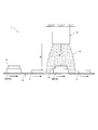
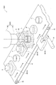
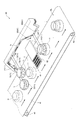
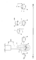
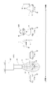
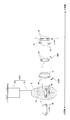
- FIG. 1 is a schematic diagram illustrating an electron beam irradiation device according to Embodiment 1 of the present invention. It is a schematic diagram showing an electron beam irradiation device according to a second embodiment of the present invention. It is the schematic which shows the electron beam irradiation apparatus which concerns on Embodiment 3 of this invention, and shows the situation in which a high dose object is irradiated with an electron beam. It is the schematic which shows the same electron beam irradiation apparatus, and shows the situation in which a low dose object is irradiated with an electron beam.
- the electron beam irradiation apparatus 1 includes a transporter 4 that transports objects H and L to be irradiated with an electron beam E, and the objects H and L transported by the transporter 4. And a single electron beam irradiator 5 for emitting an electron beam E with a constant output.
- the objects H and L may be of a plurality of types, but for simplicity of description, the following description will be made as two types. Of these two types, one is an object H requiring a high dose of the irradiated electron beam E, and the other type is a target L having a low required dose of the irradiated electron beam E.
- FIG. 1 also FIGS.
- the electron beam irradiation apparatus 1 includes an adjusting unit 10 that adjusts the electron beams E applied to the two types of objects H and L so that each of the electron beams E has a required dose.
- the single electron beam irradiator 5 irradiates the required dose of the electron beam E to each of two (a plurality of) objects H and L by the adjusting means 10.
- the adjustment means 10 converts the single dose of the electron beam E to the two (multiple) types of objects H and L into a single dose. Since the irradiation is performed by the electron beam irradiator 5, the configuration can be simplified.
- Embodiments 2 to 4 that specifically show the adjusting means 10 will be described.
- the same components as those in the first embodiment are denoted by the same reference numerals, and the description thereof will be omitted or simplified.
- the adjusting unit 10 of the electron beam irradiation apparatus 1 is a position adjuster that adjusts the position where the electron beam E is irradiated for each type of the objects H and L.
- a specific example of the position adjuster is a height adjuster 20 laid under an object H requiring a high dose of the electron beam E. Due to these height adjustment tables 20, when the electron beam E is irradiated with the electron beam E, the object H having a high required dose of the electron beam E (hereinafter referred to as the high dose object H) is connected to the electron beam irradiator 5. Becomes shorter.
- a low-dose object L when the electron beam E is irradiated, the distance D from the electron beam irradiator 5 remains long. That is, the relationship between the distances D and d between the objects H and L and the electron beam irradiator 5 when the electron beam E is irradiated is D> d. Thereby, the electron beams E applied to the two types of objects H and L each have a required dose.
- a height adjustment table may be laid under the low-dose object L.
- the height adjustment table 20 laid under the high-dose object H and the low-dose object The relationship with the height adjustment table laid under L may be any as long as D> d described above is maintained.
- the position adjuster is not limited to the height adjustment table 20, and may include a holder (not shown) for holding the high-dose object H at a high position and holding the low-dose object L at a low position. It is only necessary to adjust the position where the electron beam E is irradiated for each kind of the objects H and L.
- the electron beam irradiating apparatus 1 determines a position adjusted for each type of the objects H and L.
- a return means for returning to the original (before adjustment).
- the return means removes the height adjustment table 20 from the object H after the irradiation of the electron beam E.
- the return means is a holding height adjusting device that makes the height held by the holder the same for the high dose object H and the low dose object L. is there.
- the adjusting unit 10 adjusts the height at which the electron beam E is irradiated for each type of the target objects H and L. Since it is 20, an extremely simple configuration can be achieved.
- the high dose object H and the low dose object L irradiated with the electron beam E are next (Steps described below) (adhesion and the like as will be described later).
- the adjusting means 10 of the electron beam irradiation apparatus 1 adjusts the height of the electron beam irradiator 5 that irradiates the electron beam E for each type of the objects H and L.
- the lifting device 30 adjusts the height.
- the lifting / lowering device 30 in the high-dose target H, the distance d from the electron beam irradiator 5 set at a lower position becomes shorter.
- the distance D from the electron beam irradiator 5 set at a higher position becomes longer.
- the relationship between the distances D and d between the objects H and L and the electron beam irradiator 5 when the electron beam E is irradiated is D> d.
- the electron beams E applied to the two types of objects H and L each have a required dose.
- the lifting device 30 is used. An extremely simple configuration can be achieved.
- the adjusting means 10 of the electron beam irradiation apparatus 1 adjusts the speed at which the transfer device 4 transfers the transfer object for each type of the target objects H and L.
- the adjuster 40 As shown in FIG. 4A, when the electron beam E is irradiated on the high-dose object H, the speed adjuster 40 lowers the speed at which the high-dose object H is being conveyed. As shown, when the low-dose object L is irradiated with the electron beam E, the speed at which the low-dose object L is being conveyed is increased.
- the speed adjuster 40 irradiates the high-dose object H with the electron beam E for a long time and the low-dose object L with the electron beam E for a short time, so that the two types of objects H, Each of the electron beams E irradiated to L has a required dose.
- the speed adjuster 40 includes, for example, the driving roller 42. This adjusts the rotation speed of the motor.
- the electron beam irradiating apparatus 1 uses the transport speed adjusted for each type of the target objects H and L after the electron beam E irradiates the targets H and L.
- a return means for returning to (before adjustment) may be provided.
- a specific example of the return means is, for example, a constant-speed transport machine that transports both the high-dose object H and the low-dose object L at the same and predetermined speed after being irradiated with the electron beam E.
- the adjusting means 10 is a speed adjuster 40 that adjusts the speed at which the transfer device 4 conveys the objects H and L, An extremely simple configuration can be achieved.
- the return means returns before the transport speed adjusted for each type of the objects H and L is adjusted, the high-dose objects H and the low-dose objects L irradiated with the electron beam E are returned. Can be brought into a state suitable for the operation in the next step (such as bonding as will be described later).
- the electron beam irradiation apparatus 1 according to the fifth embodiment and a bonding facility including the electron beam irradiation apparatus 1 will be described. That is, the bonding equipment includes the electron beam irradiation device 1.
- the high-dose object H is the boss portion H
- the low-dose object L is the cylindrical portion L. It is.
- the bonded product is manufactured by fitting and bonding the tubular portion L to the boss portion H. For this bonding, the electron beam E is irradiated by the electron beam irradiation device 1 on the surface to be bonded between the boss portion H and the cylindrical portion L.
- the transporter 4 of the electron beam irradiation apparatus 1 rotates according to an endless transport belt 41, a driving roller 42 that drives the transport belt 41, and the driven transport belt 41. And a driven roller 43.
- the transport belt 41 transports the placed boss portions H and the tubular portions L alternately and continuously. Since the boss portion H is a high-dose target object H, the height adjustment table 20 is laid below.
- the electron beam irradiator 5 is a nozzle type electron beam irradiator 50 having a nozzle 51.
- the nozzle-type electron beam irradiator 50 has a vacuum chamber 53 and an electron beam generator (not shown) that is arranged inside the vacuum chamber 53 and generates an electron beam E.
- the nozzle 51 is air-tightly connected to the vacuum chamber 53 at the base end, and emits a conical electron beam E from the front end (the lower end in FIG. 5).
- the conical shape which is the shape of the emitted electron beam E, includes both a shape in which the cross section increases and a shape in which the cross section decreases from the emission source to the emission destination.
- the conical shape does not necessarily include the apex of the cone, but may be a shape including a part of the cone.
- the cone shape does not mean only a strict cone shape but also a cone shape having a shape (that is, a cloud shape) in which electrons of the electron beam E are diffused by colliding with air molecules. means. If the window for emitting the electron beam E is circular, the electron beam irradiator 5 emits the conical electron beam E described above.
- the nozzle-type electron beam irradiator 50 is disposed at a position where the axis 52 of the cylindrical portion L being conveyed coincides with the axis 52 of the nozzle 51 at a certain point in time.
- the match is not limited to a match in a strict sense, but means a match (substantially matching) including a realistic error.
- the electron beam irradiator 1 is provided with a table removing device 21 for removing the height adjustment table 20 laid under the boss H being transported, downstream of the nozzle type electron beam irradiator 50. Since the height of the boss portion H is returned before the height adjustment table 20 is laid down by removing the height adjustment table 20, the boss portion H and the tube portion L are in a state suitable for bonding. Become.
- the bonding equipment 60 includes the above-described electron beam irradiation device 1 shown in FIG. 5 and the device groups 71, 81, and 91 shown in FIG. 6 arranged downstream of the electron beam irradiation device 1. 6 include a facing device 71, a heating device 81, and a pressurizing device 91.
- the facing device 71 is a device in which the cylindrical portion L is turned upside down so that the surfaces of the boss portion H and the cylindrical portion L irradiated with the electron beam E face each other.
- the facing device 71 includes a gripper 72 for gripping the cylindrical portion L, an arm 73 extending from the gripper 72, and the cylindrical portion L gripped by the gripper 72 by rotating the arm 73.
- a rotation mechanism 74 for turning upside down.
- the facing device 71 also has a moving mechanism 75 that moves the cylindrical portion L to the downstream side in synchronization with the boss portion H being conveyed.
- the heating device 81 heats the surface of the boss H and the cylinder L irradiated with the electron beam E. For this reason, the heating device 81 is provided between the boss portion H being conveyed and the tube portion L that is synchronously moving immediately above the boss portion H, and the boss portion H and the tube portion L It has a heater 82 for heating the surface.
- the boss portion H and the cylindrical portion L pass below and above the heater 82, respectively, so that the surface is heated.
- the pressurizing device 91 lowers the cylindrical portion L gripped by the gripper 72 to the boss portion H, and presses the surfaces while contacting each other while fitting the cylindrical portion L to the boss portion H. .
- the pressurizing device 91 includes a lowering mechanism 92 that fits the cylindrical portion L to the boss portion H while moving the cylindrical portion L downstream in synchronization with the boss portion H being transported, and the boss portion H And a pressurizing mechanism 93 for moving the cylindrical portion L to the downstream side in synchronization with the boss portion H while pressurizing while fitting into the boss portion.
- the boss portion H and the tubular portion L are alternately placed on the transport belt 41.
- a height adjustment is performed below the boss portion H on the upstream side from the nozzle type electron beam irradiator 50.
- the table 20 is laid.
- the electron beam E is emitted by a single electron beam irradiator 5 with a constant output.
- An electron beam E is emitted from the nozzle type electron beam irradiator 50 with a constant output.
- the electron beam E is applied to the cylinder L, the axis 52 of the cylinder L coincides with the axis 52 of the nozzle 51 at a certain point in time.
- the height adjustment table 20 is moved to the position of the boss H by the table removal device 21. Removed from below.
- the tube portion L is gripped by the gripping tool 72 and turned upside down. It is moved directly above the section H.
- the boss portion H and the cylindrical portion L pass below and above the heater 82, respectively.
- the cylindrical portion L grasped by the grasping tool 72 is fitted to the boss portion H while being moved to the downstream side in synchronization with the boss portion H being conveyed.
- the cylinder portion L is moved to the downstream side in synchronization with the boss portion H while being pressed.
- the cylindrical portion L and the axis 52 coincide. Since the electron beam E emitted from the nozzle 51 is applied to the cylinder L, the electron beam E can be efficiently applied to the cylinder L.
- a simple configuration can be adopted for bonding the boss portion H and the cylindrical portion L by irradiation with the electron beam E.
- the bonding method is performed by using the bonding equipment 60.
- each step constituting the bonding method is performed by using one equipment such as the bonding equipment 60.
- at least one of the steps constituting the bonding method may be performed manually.
- the bonding equipment 60 has been described as including the electron beam irradiation device 1 shown in FIG. 5 and the device groups 71, 81, and 91 shown in FIG. 6, but is shown in FIG.
- an electron beam irradiation device 1 shown in any of FIGS. 1 to 4 may be provided.
- the boss H is described as the high-dose object H and the cylinder L is the low-dose object L.
- the cylinder L is the high-dose object H and the boss H is low.
- the dose object L may be used.
- the boss portion H and the cylindrical portion L described in the fifth embodiment are merely examples of two types of objects H and L to be bonded by the bonding equipment 60.
- the plurality of types of objects H and L to be bonded by the bonding equipment 60 may be anything as long as they are bonded by irradiation of the electron beam E.
- the heater 82 is not specifically described in the fifth embodiment, it is preferable that the heater 82 is an infrared heater or an infrared lamp, whereby the efficiency of bonding by the bonding equipment 60 and the bonding method can be increased.
- the heater 82 is an infrared lamp, even if the objects H and L such as the boss portion H and the cylindrical portion L are thick, the temperature unevenness in the thickness direction of the objects H and L heated by the infrared lamp. Is reduced. Thereby, the temperatures of the surfaces to be bonded of the objects H and L are appropriately made uniform, so that the bonding efficiency can be further improved.
- the environment shown in FIGS. 5 and 6 has not been described.
- an atmosphere of an inert gas for example, nitrogen gas
- the atmosphere is preferably the same as in FIG. 5 in order to simplify the configuration of the bonding equipment.
- the environment in FIGS. 5 and 6 is not limited to an inert gas atmosphere.
- the nozzle type electron beam irradiator 50 having the nozzle 51 has been described.
- the electron beam irradiator 50 that irradiates the conical electron beam E is limited to the one having the nozzle 51. Not done.
- the facing device 71 and the pressing device 91 described in the fifth embodiment are not limited to those described above, and may be, for example, those according to the following first to fourth examples.
- the transporters 4 according to the first to fourth examples are holding and transporting tools 48 and 49 for transporting while holding the boss portion H and the cylindrical portion L, respectively, as shown in FIGS. .
- the holding and conveying tools 48 and 49 according to the first and second examples basically convey the boss portion H and the tube portion L at a constant speed, but hold the boss portion H at a high position and hold the tube portion L at a high position. It also functions as a position adjuster that holds at a low position.
- the holding and conveying tools 48 and 49 hold the boss portion H and the cylindrical portion L at basically fixed positions, but lower the speed at which the boss portion H is being conveyed.
- it functions as a speed adjuster for increasing the speed at which the cylindrical portion L is being conveyed.
- the facing device 71 operates the holding / conveying tool 49 to make the cylindrical portion L after the irradiation of the electron beam E higher than the boss portion H (reference numeral).
- A) A function of reducing the transport speed to position the tubular portion L directly above the boss H immediately upstream thereof (reference numeral v) and rotate the tubular portion L by 180 ° (reference numeral 180R).
- the pressurizing device 73 according to the first example has a function of lowering the holding / conveying tool 49 to fit the cylindrical portion L into the boss portion H immediately below and pressurize the same (reference B).
- the function of positioning the tubular portion L immediately above the boss portion H immediately upstream thereof is not limited to the deceleration of the tubular portion L as indicated by the symbol v, and may be performed even when the speed of the boss portion H immediately upstream thereof is increased. Good.
- the facing device 71 operates the holding and transporting tools 48 and 49 so that the boss H after being irradiated with the electron beam E and the cylindrical portion L immediately downstream thereof. Are rotated clockwise and counterclockwise by 90 ° (reference numerals 270R and 90R), respectively, to adjust the height of the cylindrical portion L to the height of the boss portion H (reference A).
- the pressurizing device 73 according to the second example has a function of decelerating the holding / conveying tool 49 so that the cylindrical portion L is fitted to the boss portion H immediately upstream thereof and is pressurized (reference numeral v).
- the function of fitting the cylinder L to the boss H immediately upstream thereof and pressing the cylinder L is not limited to the deceleration of the cylinder L as indicated by reference numeral v, but may be a speed increase of the boss H immediately upstream thereof. .
- the facing device 71 according to the third example operates the holding / conveying tool 49 to make the cylindrical portion L after the irradiation of the electron beam E higher than the boss portion H (reference numeral).
- A) A function of reducing the transport speed to position the tubular portion L directly above the boss H immediately upstream thereof (reference numeral v) and rotate the tubular portion L by 180 ° (reference numeral 180R).
- the pressurizing device 73 according to the third example has a function of lowering the holding / conveying tool 49 so that the cylindrical portion L is fitted to the boss portion H immediately below and pressurized (reference B).
- the function of positioning the tubular portion L immediately above the boss portion H immediately upstream thereof is not limited to the deceleration of the tubular portion L as indicated by the symbol v, and may be performed even when the speed of the boss portion H immediately upstream thereof is increased. Good.
- the facing device 71 operates the holding / conveying tools 48 and 49 so that the boss portion H after being irradiated with the electron beam E and the cylindrical portion L immediately downstream thereof. Are rotated clockwise and counterclockwise by 90 °, respectively (reference numerals 270R and 90R). Further, the pressurizing device 73 according to the fourth example has a function of decelerating the holding / conveying tool 49 so that the cylindrical portion L is fitted to the boss portion H immediately upstream thereof and pressurized (reference numeral v).
- the function of fitting the cylinder L to the boss H immediately upstream thereof and pressing the cylinder L is not limited to the deceleration of the cylinder L as indicated by reference numeral v, but may be a speed increase of the boss H immediately upstream thereof. .
- the second and fourth examples described above require a smaller rotation angle than the first and third examples, and thus are suitable when the difference in weight between the cylindrical portion L and the boss portion H is small.
- the transport and rotation of the boss portion H and the cylindrical portion L by the holding and transporting tools 48 and 49 may be performed manually. Further, instead of the holding and transporting tools 48 and 49, the boss portion H and the cylindrical portion L may be manually held and transported.
- the return means (table removal device 21, holding height adjustment device and constant speed transporter) according to the second, fourth, and fifth embodiments are described as simply returning before adjustment, and adjustment is performed in a plurality of stages. Although no explanation has been given as to which stage to return to in such a case, it is also possible to return to any stage. For example, when the adjustment unit adjusts in two stages, the return unit may return to the immediately preceding stage or return to the initial stage.
- the objects H and L (including the boss portion H and the cylindrical portion L) described in the first to fifth embodiments are respectively shown in FIGS. 1 to 10 as individual objects, but as shown in FIG. Continuous sheets such as two kinds (one example of plural kinds) of long sheets H and L may be used.
- the electron beam irradiation device 1 guides the two types of long sheets to approach each other and generates an electron beam. It has guide rollers 11 and 12 where the relationship between the distance between the two types of long sheets and the electron beam irradiator 5 during irradiation is D> d.
- One of the guide rollers 11 and 12 is disposed apart from the electron beam irradiator 5 by the distance d and the thickness of the long sheet H where the required dose of the electron beam E is high.
- the guide roller 12 is disposed apart from the electron beam irradiator 5 by the distance D and the thickness of the long sheet L where the required dose of the electron beam E is low. That is, these guide rollers 11 and 12 also serve as the transporter 4 and the position adjuster (adjusting means 10).
- the equipment 60 shown in FIG. 11 includes a heating / pressing roller 94 that presses the long sheets H and L while heating the long sheets H and L downstream of the guide rollers 11 and 12. In this case, the equipment 60 becomes the bonding equipment 60.
- the guide rollers 11 and 12 also serve as the facing device 71
- the heating / pressing roller 94 also serves as the heating device 81 and the pressing device 91.
- a two-layer sheet HL is manufactured as an adhesive product HL.
- the first to fifth embodiments are illustrative in all aspects and are not restrictive.
- the scope of the present invention is defined by the terms of the claims, rather than the description above, and is intended to include any modifications within the scope and meaning equivalent to the terms of the claims.
- configurations other than the configuration described as the first or fifth invention in “Means for Solving the Problems” are arbitrary configurations, and are appropriately deleted and changed. It is possible.
Landscapes
- Engineering & Computer Science (AREA)
- Physics & Mathematics (AREA)
- General Engineering & Computer Science (AREA)
- High Energy & Nuclear Physics (AREA)
- Mechanical Engineering (AREA)
- Lining Or Joining Of Plastics Or The Like (AREA)
- Adhesives Or Adhesive Processes (AREA)
Abstract
2種の対象物(H,L)を搬送する搬送機(4)と、搬送機(4)で搬送されている2種の対象物(H,L)に一定の出力で電子線(E)を出射する単一の電子線照射器(5)とを備える電子線照射装置(1)である。電子線照射装置(1)は、2種の対象物(H,L)に照射される電子線(E)がそれぞれ必要な線量になるように調整する調整手段(10)を備える。
Description
本発明は、電子線照射装置およびこれを具備する接着設備並びに接着方法に関するものである。
電子線照射器による電子線の照射は、対象物を滅菌する目的の他にも、複数の対象物を接着するための前工程として用いられる。すなわち、対象物における電子線が照射された面は接着に適した面となり、これらの面を加熱および加圧することで、当該面を接着することが可能である。この原理を利用した電子線照射装置およびこれを具備する接着設備が、日本国特開2012-250359号公報(以下、特許文献という)に示すように、従来から提案されている。この特許文献に記載の接着設備では、2種の長尺シート(フィルム)にそれぞれ必要な線量の電子線を電子線照射装置により照射し、その後に、ローラでこれら長尺シートを貼り合わせて加圧することで、接着させている。この電子線照射装置は、2種の長尺シート(フィルム)ごとに電子線を照射する2つの電子線照射器を備える。
ところで、一般的に、電子線照射器は精密な機器なので、複数の電子線照射器を備える装置または設備は、その構成が必然的に複雑になる。このため、前記特許文献に記載の接着設備は、前述した電子線照射装置(2つの電子線照射器を備える)を具備するので、必然的に構成が複雑である。この構成を簡素にするために、電子線照射器を2つから1つに減らし、この1つの電子線照射器からの電子線の出力を前記長尺シートごとに適したものに制御することも考えられるが、この制御のために構成が却って複雑になってしまう。
そこで、本発明は、構成を簡素にし得る電子線照射装置およびこれを具備する接着設備並びに接着方法を提供することを目的とする。
前記課題を解決するため、第1の発明に係る電子線照射装置は、複数種の対象物を搬送する搬送機と、
前記搬送機で搬送されている複数種の対象物に一定の出力で電子線を出射する単一の電子線照射器と、
前記複数種の対象物に照射される電子線がそれぞれ必要な線量になるように調整する調整手段とを備えるものである。
前記搬送機で搬送されている複数種の対象物に一定の出力で電子線を出射する単一の電子線照射器と、
前記複数種の対象物に照射される電子線がそれぞれ必要な線量になるように調整する調整手段とを備えるものである。
また、第2の発明に係る電子線照射装置は、第1の発明に係る電子線照射装置における調整手段が、対象物の種ごとに、電子線が照射される位置を調整する位置調整器、または、搬送機で搬送される速度を調整する速度調整器であり、
電子線が前記対象物に照射された後で、対象物の種ごとに調整された前記位置または前記速度を、調整する前に戻すための、戻し手段を備えるものである。
電子線が前記対象物に照射された後で、対象物の種ごとに調整された前記位置または前記速度を、調整する前に戻すための、戻し手段を備えるものである。
さらに、第3の発明に係る電子線照射装置は、第1または第2の発明に係る電子線照射装置における電子線照射器が、円錐状の電子線を出射するものであり、
複数種の対象物のうちの少なくとも1種の対象物が、内部に電子線の照射が必要な筒部を有し、
前記電子線照射器が、搬送されている前記筒部のある時点での軸心と前記円錐状の電子線の軸心とが略一致する位置に配置されているものである。
複数種の対象物のうちの少なくとも1種の対象物が、内部に電子線の照射が必要な筒部を有し、
前記電子線照射器が、搬送されている前記筒部のある時点での軸心と前記円錐状の電子線の軸心とが略一致する位置に配置されているものである。
加えて、第4の発明に係る接着設備は、第1または第2の発明に係る電子線照射装置を具備し、
複数種の対象物で電子線が照射された面を互いに向かい合わせる対面装置と、
少なくとも前記面を加熱する加熱装置と、
加熱された前記面を互いに接触させて加圧する加圧装置とをさらに具備するものである。
複数種の対象物で電子線が照射された面を互いに向かい合わせる対面装置と、
少なくとも前記面を加熱する加熱装置と、
加熱された前記面を互いに接触させて加圧する加圧装置とをさらに具備するものである。
また、第5の発明に係る接着方法は、複数種の対象物を搬送する搬送工程と、
搬送されている複数種の対象物に一定の出力で電子線を単一の電子線照射器により照射する電子線照射工程と、
前記複数種の対象物に照射される電子線がそれぞれ必要な線量になるように調整する調整工程と、
複数種の対象物で電子線が照射された面を互いに向かい合わせる対面工程と、
少なくとも前記面を加熱する加熱工程と、
加熱された前記面を互いに接触させて加圧する加圧工程とを具備する方法である。
搬送されている複数種の対象物に一定の出力で電子線を単一の電子線照射器により照射する電子線照射工程と、
前記複数種の対象物に照射される電子線がそれぞれ必要な線量になるように調整する調整工程と、
複数種の対象物で電子線が照射された面を互いに向かい合わせる対面工程と、
少なくとも前記面を加熱する加熱工程と、
加熱された前記面を互いに接触させて加圧する加圧工程とを具備する方法である。
前記電子線照射装置およびこれを具備する接着設備並びに接着方法によると、前記調整手段または調整工程により、複数種の対象物にそれぞれ必要な線量の電子線が単一の電子線照射器により照射されるので、簡素な構成にすることができる。
以下、本発明の実施の形態に係る電子線照射装置およびこれを具備する接着設備並びに接着方法について、図面に基づき説明する。
まず、本発明の実施の形態1に係る電子線照射装置について、図1に基づき説明する。
[実施の形態1]
図1に示すように、この電子線照射装置1は、電子線Eが照射される対象物H,Lを搬送する搬送機4と、前記搬送機4で搬送されている前記対象物H,Lに一定の出力で電子線Eを出射する単一の電子線照射器5とを備える。前記対象物H,Lは、複数種であればよいが、説明を簡単にするために、以下では2種として説明する。これら2種のうち、1種は照射される電子線Eの必要な線量が高い対象物Hであり、他の1種は照射される電子線Eの必要な線量が低い対象物Lである。理解を容易にするために、図1では(図2~図4も)、照射される電子線Eの必要な線量が高い対象物Hの上面を凸凹で示し、照射される電子線Eの必要な線量が低い対象物Lの上面を平坦で示す。また、前記電子線照射装置1は、前記2種の対象物H,Lに照射される電子線Eがそれぞれ必要な線量になるように調整する調整手段10を備える。
図1に示すように、この電子線照射装置1は、電子線Eが照射される対象物H,Lを搬送する搬送機4と、前記搬送機4で搬送されている前記対象物H,Lに一定の出力で電子線Eを出射する単一の電子線照射器5とを備える。前記対象物H,Lは、複数種であればよいが、説明を簡単にするために、以下では2種として説明する。これら2種のうち、1種は照射される電子線Eの必要な線量が高い対象物Hであり、他の1種は照射される電子線Eの必要な線量が低い対象物Lである。理解を容易にするために、図1では(図2~図4も)、照射される電子線Eの必要な線量が高い対象物Hの上面を凸凹で示し、照射される電子線Eの必要な線量が低い対象物Lの上面を平坦で示す。また、前記電子線照射装置1は、前記2種の対象物H,Lに照射される電子線Eがそれぞれ必要な線量になるように調整する調整手段10を備える。
この調整手段10により、2種(複数種)の対象物H,Lにそれぞれ必要な線量の電子線Eが単一の電子線照射器5により照射される。
このように、本実施の形態1に係る電子線照射装置1によると、前記調整手段10により、2種(複数種)の対象物H,Lにそれぞれ必要な線量の電子線Eが単一の電子線照射器5により照射されるので、簡素な構成にすることができる。
次に、前記調整手段10を具体的に示した実施の形態2~4について説明する。以下の説明において、前記実施の形態1と同一の構成については、同一の符号を付してその説明を省略または簡略化する。
[実施の形態2]
本実施の形態2に係る電子線照射装置1の調整手段10は、対象物H,Lの種ごとに電子線Eが照射される位置を調整する位置調整器である。この位置調整器の具体例は、図2に示すように、電子線Eの必要な線量が高い対象物Hの下に敷く高さ調整台20である。これら高さ調整台20により、電子線Eの必要な線量が高い対象物H(以下では高線量対象物Hと称す)では、電子線Eが照射されている際に、電子線照射器5との距離dが短くなる。一方で、高さ調整台20を下に敷かない、電子線Eの必要な線量が低い対象物L(以下では低線量対象物Lと称す)では、電子線Eが照射されている際に、電子線照射器5との距離Dが長いままである。すなわち、電子線Eが照射されている際の対象物H,Lと電子線照射器5との距離D,dの関係はD>dとなる。これにより、前記2種の対象物H,Lに照射される電子線Eがそれぞれ必要な線量になる。
本実施の形態2に係る電子線照射装置1の調整手段10は、対象物H,Lの種ごとに電子線Eが照射される位置を調整する位置調整器である。この位置調整器の具体例は、図2に示すように、電子線Eの必要な線量が高い対象物Hの下に敷く高さ調整台20である。これら高さ調整台20により、電子線Eの必要な線量が高い対象物H(以下では高線量対象物Hと称す)では、電子線Eが照射されている際に、電子線照射器5との距離dが短くなる。一方で、高さ調整台20を下に敷かない、電子線Eの必要な線量が低い対象物L(以下では低線量対象物Lと称す)では、電子線Eが照射されている際に、電子線照射器5との距離Dが長いままである。すなわち、電子線Eが照射されている際の対象物H,Lと電子線照射器5との距離D,dの関係はD>dとなる。これにより、前記2種の対象物H,Lに照射される電子線Eがそれぞれ必要な線量になる。
必要に応じて、低線量対象物Lの下にも高さ調整台を敷いてもよいが、この場合も、高線量対象物Hの下に敷かれる高さ調整台20と、低線量対象物Lの下に敷かれる高さ調整台との関係は、前述したD>dを維持するものであればよい。
勿論、前記位置調整器は、前記高さ調整台20に限られず、高線量対象物Hを高い位置で保持するとともに低線量対象物Lを低い位置で保持する保持具(図示省略)など、対象物H,Lの種ごとに電子線Eが照射される位置を調整するものであればよい。
なお、図2には示さなかったが、前記電子線照射装置1は、電子線Eが前記対象物H,Lに照射された後で、対象物H,Lの種ごとに調整された位置を元(調整する前)に戻す戻し手段を備えてもよい。この戻し手段の具体例について説明すると、例えば、位置調整器が前記高さ調整台20の場合、戻し手段は、電子線Eが照射された後の対象物Hから高さ調整台20を撤去する台撤去機器であり、位置調整器が前記保持具の場合、戻し手段は、保持具で保持される高さを高線量対象物Hおよび低線量対象物Lで同一にする保持高さ調整機器である。
このように、本実施の形態2に係る電子線照射装置1によると、前記調整手段10が、対象物H,Lの種ごとに電子線Eが照射される高さを調整する高さ調整台20なので、極めて簡素な構成にすることができる。
また、戻し手段により、対象物H,Lの種ごとに調整された位置が調整される前に戻されるので、電子線Eが照射された高線量対象物Hおよび低線量対象物Lを、次の工程での作業(後述するが接着など)に適した状態にすることができる。
[実施の形態3]
本実施の形態3に係る電子線照射装置1の調整手段10は、図3Aおよび図3Bに示すように、対象物H,Lの種ごとに電子線Eを照射する電子線照射器5の高さを調整する昇降機器30である。この昇降機器30により、高線量対象物Hでは、低い位置にされた電子線照射器5との距離dが短くなる。一方で、低線量対象物Lでは、高い位置にされた電子線照射器5との距離Dが長くなる。すなわち、電子線Eが照射されている際の対象物H,Lと電子線照射器5との距離D,dの関係はD>dとなる。これにより、前記2種の対象物H,Lに照射される電子線Eがそれぞれ必要な線量になる。
本実施の形態3に係る電子線照射装置1の調整手段10は、図3Aおよび図3Bに示すように、対象物H,Lの種ごとに電子線Eを照射する電子線照射器5の高さを調整する昇降機器30である。この昇降機器30により、高線量対象物Hでは、低い位置にされた電子線照射器5との距離dが短くなる。一方で、低線量対象物Lでは、高い位置にされた電子線照射器5との距離Dが長くなる。すなわち、電子線Eが照射されている際の対象物H,Lと電子線照射器5との距離D,dの関係はD>dとなる。これにより、前記2種の対象物H,Lに照射される電子線Eがそれぞれ必要な線量になる。
このように、本実施の形態3に係る電子線照射装置1によると、対象物H,Lの種ごとに電子線Eを照射する電子線照射器5の高さを調整する昇降機器30なので、極めて簡素な構成にすることができる。
[実施の形態4]
本実施の形態4に係る電子線照射装置1の調整手段10は、図4Aおよび図4Bに示すように、対象物H,Lの種ごとに、搬送機4で搬送される速度を調整する速度調整器40である。この速度調整器40は、図4Aに示すように、高線量対象物Hに電子線Eが照射されている際には当該高線量対象物Hの搬送されている速度を低くし、図4Bに示すように、低線量対象物Lに電子線Eが照射されている際には当該低線量対象物Lの搬送されている速度を高くするものである。前記速度調整器40により、高線量対象物Hには電子線Eが長時間照射されるとともに低線量対象物Lには電子線Eが短時間照射されるので、前記2種の対象物H,Lに照射される電子線Eがそれぞれ必要な線量になる。
本実施の形態4に係る電子線照射装置1の調整手段10は、図4Aおよび図4Bに示すように、対象物H,Lの種ごとに、搬送機4で搬送される速度を調整する速度調整器40である。この速度調整器40は、図4Aに示すように、高線量対象物Hに電子線Eが照射されている際には当該高線量対象物Hの搬送されている速度を低くし、図4Bに示すように、低線量対象物Lに電子線Eが照射されている際には当該低線量対象物Lの搬送されている速度を高くするものである。前記速度調整器40により、高線量対象物Hには電子線Eが長時間照射されるとともに低線量対象物Lには電子線Eが短時間照射されるので、前記2種の対象物H,Lに照射される電子線Eがそれぞれ必要な線量になる。
図4Aおよび図4Bに示すように、前記搬送機4が搬送用ベルト41並びにローラ42,43(駆動ローラ42および従動ローラ43)を有する場合、前記速度調整器40は、例えば、前記駆動ローラ42の回転速度を調整するものである。
なお、図示しないが、前記電子線照射装置1は、電子線Eが前記対象物H,Lに照射された後で、対象物H,Lの種ごとに調整された搬送される速度を元(調整する前)に戻す戻し手段を備えてもよい。この戻し手段の具体例は、例えば、電子線Eが照射された後の高線量対象物Hおよび低線量対象物Lをいずれも同一且つ所定の速度で搬送する定速搬送機である。
このように、本実施の形態4に係る電子線照射装置1によると、前記調整手段10が対象物H,Lの種ごとに搬送機4で搬送される速度を調整する速度調整器40なので、極めて簡素な構成にすることができる。
また、戻し手段により、対象物H,Lの種ごとに調整された搬送される速度が調整される前に戻されるので、電子線Eが照射された高線量対象物Hおよび低線量対象物Lを、次の工程での作業(後述するが接着など)に適した状態にすることができる。
[実施の形態5]
以下、本実施の形態5に係る電子線照射装置1、および、この電子線照射装置1を具備する接着設備について説明する。すなわち、この接着設備は、前記電子線照射装置1を具備するものである。
以下、本実施の形態5に係る電子線照射装置1、および、この電子線照射装置1を具備する接着設備について説明する。すなわち、この接着設備は、前記電子線照射装置1を具備するものである。
まず、前記電子線照射装置1について図5に基づき説明し、次いで、前記接着設備について図6に基づき説明する。
図5に示すように、前記電子線照射装置1で電子線Eが照射される対象物H,Lのうち、高線量対象物Hがボス部Hであり、低線量対象物Lが筒部Lである。ボス部Hに筒部Lが嵌められて接着することにより、接着製品が製造される。この接着のために、ボス部Hおよび筒部Lの接着させる面に電子線照射装置1で電子線Eを照射する。
本実施の形態5に係る電子線照射装置1の搬送機4は、無端状の搬送用ベルト41と、この搬送用ベルト41を駆動する駆動ローラ42と、駆動された搬送用ベルト41に従って回転する従動ローラ43とを有する。搬送用ベルト41は、載置されたボス部Hおよび筒部Lを交互に連続して搬送するものである。ボス部Hは、高線量対象物Hなので、下に高さ調整台20が敷かれる。
電子線照射器5は、ノズル51を有するノズル式電子線照射器50である。このノズル式電子線照射器50は、真空チャンバ53と、この真空チャンバ53の内部に配置されて電子線Eを発生させる電子線発生部(図示省略)とを有する。前記ノズル51は、真空チャンバ53と基端で気密に接続されて先端(図5では下端)から円錐状の電子線Eを出射するものである。ここで、出射された電子線Eの形状である円錐状とは、出射元から出射先にかけて横断面が大きくなる形状および小さくなる形状のいずれをも含む。また、前記円錐状は、円錐の頂点を必ずしも含まず、円錐の一部を含む形状であればよい。さらに、前記円錐状は、厳密な円錐状のみを意味するのではなく、電子線Eの電子が空気の分子に衝突することで拡散することを考慮した形状(つまり雲状)の円錐状までも意味する。電子線照射器5は、その電子線Eを出射するための窓が円形状であれば、前述した円錐状の電子線Eを出射する。前記ノズル式電子線照射器50は、搬送されている筒部Lの軸心52と前記ノズル51の軸心52とがある時点で一致する位置に配置される。ここで、一致とは、厳密な意味での一致に限られず、現実的な誤差も含めた一致(略一致)を意味する。
前記電子線照射装置1は、前記ノズル式電子線照射器50の下流側に、搬送されているボス部Hの下に敷かれた高さ調整台20を撤去する台撤去機器21を備える。高さ調整台20が撤去されることで、ボス部Hの高さが下に高さ調整台20を敷く前に戻されるので、ボス部Hおよび筒部Lが接着するのに適した状態になる。
次に、前記電子線照射装置1を備える接着設備60について説明する。
この接着設備60は、図5に示す前述した電子線照射装置1と、この電子線照射装置1よりも下流側に配置された図6に示す装置群71,81,91とを具備する。図6に示す装置群71,81,91は、対面装置71、加熱装置81および加圧装置91を備える。
前記対面装置71は、筒部Lを上下反転させて、ボス部Hと筒部Lとで電子線Eが照射された面を互いに向かい合わせるものである。このため、前記対面装置71は、筒部Lを把持する把持具72と、この把持具72から延びたアーム73と、このアーム73を回転させることで把持具72に把持された筒部Lを上下反転させる回転機構74とを有する。また前記対面装置71は、搬送されているボス部Hの直上方で同期して筒部Lを下流側に移動させる移動機構75も有する。
前記加熱装置81は、ボス部Hと筒部Lとで電子線Eが照射された面を加熱するものである。このため、加熱装置81は、搬送されているボス部Hと、このボス部Hの直上方で同期して移動している筒部Lとの間に、当該ボス部Hおよび筒部Lの前記面を加熱するヒータ82を有する。前記ボス部Hおよび筒部Lは、前記ヒータ82のそれぞれ下方および上方を通過することで、前記面が加熱される。
前記加圧装置91は、把持具72で把持された筒部Lをボス部Hまで下降させて、当該筒部Lをボス部Hに嵌めながら、前記面を互いに接触させて加圧するものである。このため、前記加圧装置91は、搬送されているボス部Hに同期して筒部Lを下流側に移動させながら当該ボス部Hに嵌める下降機構92と、前記筒部Lをボス部Hに嵌めながら加圧しつつ当該ボス部Hに同期して筒部Lを下流側に移動させる加圧機構93とを有する。
以下、前記接着設備60の使用方法、すなわち接着方法について説明する。
図5に示すように、ボス部Hおよび筒部Lを搬送する搬送工程として、ボス部Hおよび筒部Lが交互に搬送用ベルト41に載置される。ボス部Hおよび筒部Lに照射される電子線Eがそれぞれ必要な線量になるように調整する調整工程として、ノズル式電子線照射器50から上流側のボス部Hの下には高さ調整台20が敷かれる。
ボス部Hおよび筒部Lは、ノズル式電子線照射器50の下方まで搬送されると、一定の出力で電子線Eを単一の電子線照射器5により出射する電子線出射工程として、このノズル式電子線照射器50から一定の出力で電子線Eが出射される。筒部Lに電子線Eが照射されている際には、筒部Lの軸心52とノズル51の軸心52とがある時点で一致する。
ボス部Hに電子線Eが照射された後に、高さ調整台20で調整された前記高さを調整する前に戻す戻し工程として、台撤去機器21により高さ調整台20がボス部Hの下から撤去される。
図6に示すように、ボス部Hおよび筒部Lで電子線Eが照射された面を互いに向かい合わせる対面工程として、筒部Lが把持具72に把持されて上下に反転されるとともに、ボス部Hの直上方に移動される。
少なくとも前記面を加熱する加熱工程として、ボス部Hおよび筒部Lは、前記ヒータ82のそれぞれ下方および上方を通過する。
前記面を互いに接触させて加圧する加圧工程として、搬送されているボス部Hに同期して把持具72で把持された筒部Lを下流側に移動させながらボス部Hに嵌め、そのまま加圧しつつボス部Hに同期して筒部Lを下流側に移動させる。
この結果、ボス部Hと筒部Lとが接着することで、接着製品HLが製造される。
このように、本実施の形態5に係る電子線照射装置1によると、前記実施の形態1および2に係る電子線照射装置1の効果を奏する上に、筒部Lと軸心52が一致するノズル51から出射する電子線Eを当該筒部Lに照射するので、当該筒部Lに効率よく電子線Eを照射することができる。
また、本実施の形態5に係る接着設備60および接着方法によると、電子線Eの照射でボス部Hと筒部Lとを接着するのに、簡素な構成にすることができる。
ところで、前記実施の形態5では、接着方法が前記接着設備60の使用により行われるとして説明したが、当該接着方法を構成する各工程は、前記接着設備60のような1つの設備の使用により行われることに限らない。例えば、前記接着方法を構成する工程の少なくとも1つは、人手により行われてもよい。
また、前記実施の形態5では、前記接着設備60が、図5に示す電子線照射装置1と、図6に示す装置群71,81,91とを具備するとして説明したが、図5に示す電子線照射装置1の代わりに、図1~図4のいずれかに示す電子線照射装置1を具備してもよい。
加えて、前記実施の形態5では、ボス部Hが高線量対象物Hで筒部Lが低線量対象物Lである説明したが、筒部Lが高線量対象物Hでボス部Hが低線量対象物Lでもよい。
また、前記実施の形態5で説明したボス部Hおよび筒部Lは、接着設備60で接着するための2種の対象物H,Lの一例に過ぎない。接着設備60で接着する複数種の対象物H,Lは、電子線Eの照射により接着するものであれば、何でもよい。
また、前記実施の形態5ではヒータ82について具体的に説明しなかったが、赤外線ヒータまたは赤外線ランプであることが好ましく、これにより、接着設備60および接着方法による接着の効率を高めることができる。特に、ヒータ82が赤外線ランプであることにより、ボス部Hおよび筒部Lなどの対象物H,Lが厚くても、赤外線ランプで加熱された当該対象物H,Lの厚さ方向における温度ムラが低減される。これにより、当該対象物H,Lの接着させる面の温度が適切に均一化されるので、接着の効率を一層高めることができる。
また、前記実施の形態5では、図5および図6に示す環境について説明しなかったが、図5では不活性ガス(例えば窒素ガス)の雰囲気下であることがオゾンを発生させないためにも好ましく、図6では接着設備の構成を簡素にするためにも図5と同じ雰囲気下であることが好ましい。勿論、図5および図6の環境は、不活性ガスの雰囲気下であることに限定されない。
また、前記実施の形態5では、ノズル51を有するノズル式電子線照射器50について説明したが、円錐状の電子線Eを照射する電子線照射器50であれば、ノズル51を有するものに限定されない。
また、前記実施の形態5で説明した対面装置71および加圧装置91は、前述したものに限定されず、例えば以下の第1例~第4例に係るものでもよい。以下において、第1例~第4例に係る搬送機4は、図7~図10に示すように、ボス部Hおよび筒部Lをそれぞれ保持しながら搬送するする保持搬送具48,49である。第1例および第2例に係る保持搬送具48,49は、ボス部Hおよび筒部Lを基本的に一定の速度で搬送するが、ボス部Hを高い位置で保持するとともに筒部Lを低い位置で保持する位置調整器としても機能する。また、第3例および第4例に係る保持搬送具48,49は、ボス部Hおよび筒部Lを基本的に一定の位置で保持するが、ボス部Hの搬送されている速度を低くするとともに筒部Lの搬送されている速度を高くする速度調整器としても機能する。
前記第1例に係る対面装置71は、図7に示すように、保持搬送具49を操作することで、電子線Eが照射された後の筒部Lをボス部Hよりも高くし(符号A)、搬送の速度を減速することで前記筒部Lをその直上流のボス部Hの直上方に位置させ(符号v)、筒部Lを180°回転させる(符号180R)、という機能を有する。また、前記第1例に係る加圧装置73は、保持搬送具49を下降させることで、筒部Lを直下方のボス部Hに嵌めて加圧する(符号B)、という機能を有する。なお、筒部Lをその直上流のボス部Hの直上方に位置させる機能は、符号vで示すような筒部Lの減速に限定されず、その直上流のボス部Hの増速などでもよい。
前記第2例に係る対面装置71は、図8に示すように、保持搬送具48,49を操作することで、電子線Eが照射された後のボス部Hおよびその直下流の筒部Lをそれぞれ時計回りおよび反時計回りに90°回転させ(符号270Rおよび符号90R)、前記筒部Lの高さを前記ボス部Hの高さに合わせる(符号A)、という機能を有する。また、前記第2例に係る加圧装置73は、保持搬送具49を減速することで、筒部Lをその直上流のボス部Hに嵌めて加圧する(符号v)、という機能を有する。なお、筒部Lをその直上流のボス部Hに嵌めて加圧する機能は、符号vで示すような筒部Lの減速に限定されず、その直上流のボス部Hの増速などでもよい。
前記第3例に係る対面装置71は、図9に示すように、保持搬送具49を操作することで、電子線Eが照射された後の筒部Lをボス部Hよりも高くし(符号A)、搬送の速度を減速することで前記筒部Lをその直上流のボス部Hの直上方に位置させ(符号v)、筒部Lを180°回転させる(符号180R)、という機能を有する。また、前記第3例に係る加圧装置73は、保持搬送具49を下降させることで、筒部Lを直下方のボス部Hに嵌めて加圧する(符号B)、という機能を有する。なお、筒部Lをその直上流のボス部Hの直上方に位置させる機能は、符号vで示すような筒部Lの減速に限定されず、その直上流のボス部Hの増速などでもよい。
前記第4例に係る対面装置71は、図10に示すように、保持搬送具48,49を操作することで、電子線Eが照射された後のボス部Hおよびその直下流の筒部Lをそれぞれ時計回りおよび反時計回りに90°回転させる(符号270Rおよび符号90R)、という機能を有する。また、前記第4例に係る加圧装置73は、保持搬送具49を減速することで、筒部Lをその直上流のボス部Hに嵌めて加圧する(符号v)、という機能を有する。なお、筒部Lをその直上流のボス部Hに嵌めて加圧する機能は、符号vで示すような筒部Lの減速に限定されず、その直上流のボス部Hの増速などでもよい。
前述した第1例および第3例では、筒部Lを保持して搬送する保持搬送具49のみを回転させれば済むので、筒部Lがボス部Hに比べて十分軽量である場合に適する。一方で、前述した第2例および第4例では、第1例および第3例よりも少ない回転の角度で済むので、筒部Lとボス部Hとの重量の差が小さい場合に適する。
保持搬送具48,49によるボス部Hおよび筒部Lの搬送および回転は、人手により行われてもよい。また、保持搬送具48,49の代わりに、人手でボス部Hおよび筒部Lを保持して搬送してもよい。
また、前記実施の形態2,4および5に係る戻し手段(台撤去機器21、保持高さ調整機器および定速搬送機)は、単に調整する前に戻すものとして説明し、複数の段階で調整した場合にどの段階まで戻すか説明しなかったが、いずれの段階まで戻すものでもよい。例えば、調整手段が2つの段階で調整した場合、戻し手段は、直前の段階まで戻すものでもよく、当初の段階まで戻すものでもよい。
また、前記実施の形態1~5で説明した対象物H,L(ボス部Hおよび筒部Lも含む)は、それぞれ個別の物として図1~図10に示したが、図11に示すような2種(複数種の一例)の長尺シートH,Lなど、連続したものでもよい。図11に示すように、対象物H,Lが2種の長尺シートH,Lの場合、電子線照射装置1は、これら2種の長尺シートが互いに近づくように導くとともに、電子線が照射されている際の2種の長尺シートと電子線照射器5との距離の関係をD>dとする案内ローラ11,12を有する。これら案内ローラ11,12のうち、一方の案内ローラ11は、電子線Eの必要な線量が高い長尺シートHの厚さおよび前記距離dだけ電子線照射器5から離されて配置され、他方の案内ローラ12は、電子線Eの必要な線量が低い長尺シートLの厚さおよび前記距離Dだけ電子線照射器5から離されて配置される。すなわち、これら案内ローラ11,12が、前記搬送機4および位置調整器(調整手段10)を兼ねる。さらに、図11に示す設備60が、この電子線照射装置1の他に、前記案内ローラ11,12の下流側に長尺シートH,Lを加熱しながら加圧する加熱兼加圧ローラ94を具備する場合、当該設備60は前記接着設備60となる。この場合、前記案内ローラ11,12が前記対面装置71も兼ねるとともに、前記加熱兼加圧ローラ94が前記加熱装置81および加圧装置91を兼ねる。これら加熱兼加圧ローラ94より下流側で、接着製品HLとして2層シートHLが製造される。
また、前記実施の形態1~5は、全ての点で例示であって制限的なものではない。本発明の範囲は、前述した説明ではなく特許請求の範囲によって示され、特許請求の範囲と均等の意味および範囲内での全ての変更が含まれることが意図される。前記実施の形態1~5で説明した構成のうち「課題を解決するための手段」での第1または第5の発明として記載した構成以外については、任意の構成であり、適宜削除および変更することが可能である。
Claims (5)
- 複数種の対象物を搬送する搬送機と、
前記搬送機で搬送されている複数種の対象物に一定の出力で電子線を出射する単一の電子線照射器と、
前記複数種の対象物に照射される電子線がそれぞれ必要な線量になるように調整する調整手段とを備えることを特徴とする電子線照射装置。 - 調整手段が、対象物の種ごとに、電子線が照射される位置を調整する位置調整器、または、搬送機で搬送される速度を調整する速度調整器であり、
電子線が前記対象物に照射された後で、対象物の種ごとに調整された前記位置または前記速度を、調整する前に戻すための、戻し手段を備えることを特徴とする請求項1に記載の電子線照射装置。 - 電子線照射器が、円錐状の電子線を出射するものであり、
複数種の対象物のうちの少なくとも1種の対象物が、内部に電子線の照射が必要な筒部を有し、
前記電子線照射器が、搬送されている前記筒部のある時点での軸心と前記円錐状の電子線の軸心とが略一致する位置に配置されていることを特徴とする請求項1または2に記載の電子線照射装置。 - 請求項1または2に記載の電子線照射装置を具備し、
複数種の対象物で電子線が照射された面を互いに向かい合わせる対面装置と、
少なくとも前記面を加熱する加熱装置と、
加熱された前記面を互いに接触させて加圧する加圧装置とをさらに具備することを特徴とする接着設備。 - 複数種の対象物を搬送する搬送工程と、
搬送されている複数種の対象物に一定の出力で電子線を単一の電子線照射器により照射する電子線照射工程と、
前記複数種の対象物に照射される電子線がそれぞれ必要な線量になるように調整する調整工程と、
複数種の対象物で電子線が照射された面を互いに向かい合わせる対面工程と、
少なくとも前記面を加熱する加熱工程と、
加熱された前記面を互いに接触させて加圧する加圧工程とを具備することを特徴とする接着方法。
Applications Claiming Priority (2)
| Application Number | Priority Date | Filing Date | Title |
|---|---|---|---|
| JP2018-153339 | 2018-08-17 | ||
| JP2018153339A JP2020027078A (ja) | 2018-08-17 | 2018-08-17 | 電子線照射装置およびこれを具備する接着設備並びに接着方法 |
Publications (1)
| Publication Number | Publication Date |
|---|---|
| WO2020036056A1 true WO2020036056A1 (ja) | 2020-02-20 |
Family
ID=69524799
Family Applications (1)
| Application Number | Title | Priority Date | Filing Date |
|---|---|---|---|
| PCT/JP2019/029641 Ceased WO2020036056A1 (ja) | 2018-08-17 | 2019-07-29 | 電子線照射装置およびこれを具備する接着設備並びに接着方法 |
Country Status (2)
| Country | Link |
|---|---|
| JP (1) | JP2020027078A (ja) |
| WO (1) | WO2020036056A1 (ja) |
Citations (3)
| Publication number | Priority date | Publication date | Assignee | Title |
|---|---|---|---|---|
| JPH0252200U (ja) * | 1988-10-05 | 1990-04-13 | ||
| JPH02134600A (ja) * | 1988-11-15 | 1990-05-23 | Nissin High Voltage Co Ltd | 電子線照射装置 |
| JP2014030917A (ja) * | 2012-08-01 | 2014-02-20 | Dainippon Printing Co Ltd | 連続フィルム基材の貼合せ装置および連続フィルム基材の貼合せ方法 |
-
2018
- 2018-08-17 JP JP2018153339A patent/JP2020027078A/ja active Pending
-
2019
- 2019-07-29 WO PCT/JP2019/029641 patent/WO2020036056A1/ja not_active Ceased
Patent Citations (3)
| Publication number | Priority date | Publication date | Assignee | Title |
|---|---|---|---|---|
| JPH0252200U (ja) * | 1988-10-05 | 1990-04-13 | ||
| JPH02134600A (ja) * | 1988-11-15 | 1990-05-23 | Nissin High Voltage Co Ltd | 電子線照射装置 |
| JP2014030917A (ja) * | 2012-08-01 | 2014-02-20 | Dainippon Printing Co Ltd | 連続フィルム基材の貼合せ装置および連続フィルム基材の貼合せ方法 |
Also Published As
| Publication number | Publication date |
|---|---|
| JP2020027078A (ja) | 2020-02-20 |
Similar Documents
| Publication | Publication Date | Title |
|---|---|---|
| CN101017767B (zh) | 工件粘贴支承方法和使用该方法的工件粘贴支承装置 | |
| US11939200B2 (en) | Apparatus and method for treating containers | |
| US8278632B2 (en) | Vessel sterilization apparatus | |
| CN211222617U (zh) | 饮料加工业中对容器的表面进行处理的容器处理机 | |
| WO2020036056A1 (ja) | 電子線照射装置およびこれを具備する接着設備並びに接着方法 | |
| KR101677154B1 (ko) | 단차 가공용 레이저 절단 장치 | |
| CN101801422A (zh) | β辐射灭菌 | |
| JP6748229B2 (ja) | ラベルを製品に装着するための方法、装置、およびシステム | |
| JP2007297067A (ja) | 開口容器用電子線照射装置 | |
| EP4085935A1 (en) | Sterilizer | |
| WO2018037847A1 (ja) | 電子線滅菌設備 | |
| WO2018180464A1 (ja) | 電子線滅菌装置および電子線滅菌方法 | |
| CN1258338C (zh) | 加工设备和加工方法 | |
| JPH08217237A (ja) | 対象物を搬送装置に供給するための方法及び装置 | |
| JPH101243A (ja) | フィルム材固定機構 | |
| JP2015085317A (ja) | 接着剤塗布装置、接着剤塗布方法、表示装置用部材の製造装置及び表示装置用部材の製造方法 | |
| JPH11321831A (ja) | ラベリング装置 | |
| JP2004347510A (ja) | 電子線照射装置、電子線照射方法、および電子線被照射物 | |
| CN107923026B (zh) | 钢板着色装置和钢板着色方法 | |
| KR102269052B1 (ko) | 레이저 절단 시스템 | |
| US12509263B2 (en) | Packaging apparatus | |
| JP3970301B2 (ja) | 回路部品装着システム | |
| JP2016043340A (ja) | フレキシブルデバイスの生成装置および生成方法 | |
| CN112938378B (zh) | 随形试管夹持与运送系统 | |
| JP2010188580A (ja) | ナノインプリント装置 |
Legal Events
| Date | Code | Title | Description |
|---|---|---|---|
| 121 | Ep: the epo has been informed by wipo that ep was designated in this application |
Ref document number: 19850692 Country of ref document: EP Kind code of ref document: A1 |
|
| NENP | Non-entry into the national phase |
Ref country code: DE |
|
| 122 | Ep: pct application non-entry in european phase |
Ref document number: 19850692 Country of ref document: EP Kind code of ref document: A1 |