WO2020036032A1 - レンズ光学系及び撮像装置 - Google Patents
レンズ光学系及び撮像装置 Download PDFInfo
- Publication number
- WO2020036032A1 WO2020036032A1 PCT/JP2019/027771 JP2019027771W WO2020036032A1 WO 2020036032 A1 WO2020036032 A1 WO 2020036032A1 JP 2019027771 W JP2019027771 W JP 2019027771W WO 2020036032 A1 WO2020036032 A1 WO 2020036032A1
- Authority
- WO
- WIPO (PCT)
- Prior art keywords
- lens
- optical system
- lens optical
- wavelength
- conditional expression
- Prior art date
- Legal status (The legal status is an assumption and is not a legal conclusion. Google has not performed a legal analysis and makes no representation as to the accuracy of the status listed.)
- Ceased
Links
Images


Classifications
-
- G—PHYSICS
- G02—OPTICS
- G02B—OPTICAL ELEMENTS, SYSTEMS OR APPARATUS
- G02B13/00—Optical objectives specially designed for the purposes specified below
-
- G—PHYSICS
- G02—OPTICS
- G02B—OPTICAL ELEMENTS, SYSTEMS OR APPARATUS
- G02B13/00—Optical objectives specially designed for the purposes specified below
- G02B13/14—Optical objectives specially designed for the purposes specified below for use with infrared or ultraviolet radiation
-
- G—PHYSICS
- G02—OPTICS
- G02B—OPTICAL ELEMENTS, SYSTEMS OR APPARATUS
- G02B13/00—Optical objectives specially designed for the purposes specified below
- G02B13/18—Optical objectives specially designed for the purposes specified below with lenses having one or more non-spherical faces, e.g. for reducing geometrical aberration
-
- G—PHYSICS
- G02—OPTICS
- G02B—OPTICAL ELEMENTS, SYSTEMS OR APPARATUS
- G02B5/00—Optical elements other than lenses
- G02B5/20—Filters
- G02B5/28—Interference filters
Definitions
- the present invention relates to a lens optical system and an imaging device used for a light beam having a specific wavelength and having high performance for a light beam having a specific wavelength.
- a lens group composed of three lenses and an interference filter that transmits light in a specific wavelength band in the near infrared region are connected from the object side to the image side.
- the lens group includes a first meniscus lens convex to the object side having positive power, and a convex lens convex to the image side having positive power from the object side to the image side.
- An infrared lens unit provided in order has been proposed (for example, see Patent Document 1).
- a wide-angle lens is configured with a small number of lenses of three or less.
- the Fno is dark and the angle of incidence on the image sensor is large, the amount of light incident on the image sensor is small. There is a problem that it is not enough.
- the present invention has been made in view of the above-described problem, and has as its object to provide a lens optical system and an image pickup apparatus that efficiently input reflected light or scattered light from an object to an image pickup device.
- a first invention is a lens optical system used only within a wavelength range of wavelength N ⁇ 50 nm, wherein the lens optical system has a band-pass filter transmitting only within a wavelength range of wavelength N ⁇ 50 nm,
- a lens optical system characterized in that the system has at least one surface having negative refractive power and satisfies the following conditional expression. -2.00 ⁇ fn / f ⁇ -0.45 (1) 0.10 ⁇ Y / f ⁇ 0.60 (2) However, fn: focal length at the wavelength Nnm of the surface having the largest negative refractive power among all surfaces of the lens optical system f: focal length Y at the wavelength Nnm of the lens optical system Y: maximum at the wavelength Nnm of the lens optical system The image height.
- the second invention is An image pickup apparatus comprising: the lens optical system according to the first invention; and an image pickup device that converts an optical image formed by the lens optical system into an electric signal.
- the present invention it is possible to configure a lens optical system and an imaging device that efficiently input reflected light or scattered light from an object to an imaging device.
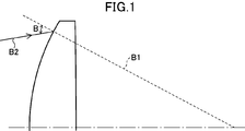
- FIG. 4 is an explanatory diagram of a term “light incident angle B”. It is explanatory drawing of a term “ray incident angle C”. It is explanatory drawing of a term “ray incident angle D”. It is explanatory drawing of the term "tangent angle of a lens surface.”
- FIG. 2 is a lens cross-sectional view illustrating a lens configuration of a lens optical system according to a first example of the present invention.
- FIG. 3 is a longitudinal aberration diagram of the lens optical system according to the first example of the present invention. It is a lens sectional view showing the lens composition of the lens optical system of the 2nd example of the present invention.
- FIG. 10 is a longitudinal aberration diagram of the lens optical system according to Example 2 of the present invention.
- FIG. 1 is an explanatory diagram illustrating a configuration of an imaging device according to an embodiment of the present invention.
- the lens optical system according to the first embodiment includes: In a lens optical system used only within a wavelength range of wavelength N ⁇ 50 nm, the lens optical system has a band-pass filter that transmits only within a wavelength range of wavelength N ⁇ 50 nm, and the lens optical system is negative.
- fn focal length at the wavelength Nnm of the surface having the largest negative refractive power among all surfaces of the lens optical system
- f focal length Y at the wavelength Nnm of the lens optical system
- Y maximum at the wavelength Nnm of the lens optical system
- the lens optical system according to the first embodiment is a lens optical system used only within a wavelength range of wavelength N ⁇ 50 nm, wherein the lens optical system has a band-pass filter that transmits only the wavelength range of wavelength N ⁇ 50 nm. It is characterized by the following.
- the band-pass filter is an interference filter formed by forming a multilayer film on the surface of the substrate, and has a function of increasing the transmittance of light in a specific wavelength band and decreasing the transmittance of other wavelength bands.
- the position of the bandpass filter in the direction of the optical axis does not matter. However, since the transmission spectrum of the interference filter shifts to the shorter wavelength side as the incident light beam angle departs from 0 °, it is preferable to dispose the bandpass filter at a position where the light incident angle to the bandpass filter is not large. In addition, the curvature of the base of the band-pass filter does not matter. However, it is preferable that the substrate is a parallel plate because the light enters the bandpass filter at various angles and the angle of incidence of the light varies depending on the incident position when the substrate is spherical.
- the lens optical system according to the first embodiment is characterized in that at least one surface having negative refractive power is provided.
- at least one surface having negative refractive power is provided.
- at least one surface has a negative refractive power.
- the lens optical system according to the first embodiment satisfies the following conditional expression. ⁇ 2.00 ⁇ fn / f ⁇ 0.45 (1)
- fn focal length at the wavelength Nnm of the surface having the largest negative refractive power among all surfaces of the lens optical system
- f focal length at the wavelength Nnm of the lens optical system
- conditional expression (1) is an expression for defining the focal length of the surface having the negative refractive power.
- the focal length of the surface having the negative refractive power falls within an appropriate range, and the image surface property can be corrected with a lens configuration that does not require a large number of lenses. If the lower limit of conditional expression (1) is exceeded, the negative refractive power becomes too weak, making it difficult to correct the image surface properties, which is not preferable.
- the value exceeds the upper limit of the conditional expression (1) the negative refractive power becomes too strong and the image surface property is excessively deteriorated, which is not preferable in terms of performance. Further, it is difficult to correct the image plane property with a small number of lenses, which is not preferable in terms of cost reduction.
- the lower limit of conditional expression (1) is more preferably -1.80, further preferably -1.60, further preferably -1.50, and still more preferably -1.40, More preferably, it is ⁇ 1.30, and still more preferably ⁇ 1.20.
- the upper limit of conditional expression (1) is preferably -0.50, more preferably -0.55, further preferably -0.60, further preferably -0.65, and- More preferably, it is 0.70.
- the lens optical system according to the first embodiment satisfies the following conditional expression. 0.10 ⁇ Y / f ⁇ 0.60 (2) However, Y: maximum image height at the wavelength Nnm of the lens optical system f: focal length at the wavelength Nnm of the lens optical system
- conditional expression (2) is an expression that defines the ratio between the maximum image height of the lens optical system and the focal length.
- the lower limit of conditional expression (2) is more preferably 0.12, further preferably 0.14, further preferably 0.16, and even more preferably 0.20. Further, the upper limit of conditional expression (2) is preferably 0.55, more preferably 0.50, further preferably 0.45, further preferably 0.40, and more preferably 0.35. Is more preferable.
- the imaging optical system of the first embodiment is not limited to this lens configuration. Regardless of the number of lenses and the arrangement of the lenses, these effects can be obtained by applying the present embodiment. In addition, from the viewpoint of cost reduction and miniaturization, it is more preferable to configure the camera with seven or less lenses. Regarding the shape of the lens, it is preferable that the outermost object side surface is a convex surface. The number and shape of the lenses can be appropriately changed according to the required focal length, size, F number, and image height.
- the lens optical system according to the second embodiment has at least one resin lens Lp.
- a resin lens weight reduction and cost reduction can be achieved.
- the resin lens Lp has an aspheric surface.
- an aspherical surface for the resin lens Lp Aberrations can be effectively corrected while realizing cost reduction, so that high performance is also achieved.
- the resin lens Lp be an aspherical surface having a shape that reduces paraxial refracting power in order to correct aberration.
- the lens optical system according to the third embodiment is characterized in that the resin lens Lp satisfies the following conditional expression. 1.5 ⁇
- fLp Focal length at the wavelength Nnm of the resin lens
- f Focal length at the wavelength Nnm of the lens optical system (if there are a plurality of resin lenses Lp, fLp is the one with the largest refractive power).
- the conditional expression (3) is an expression for defining the focal length of the resin lens Lp at the wavelength Nnm.
- the resin lens Lp since the change in optical characteristics with respect to a temperature change is large, it is better that the resin lens Lp does not have a very large refractive power.
- conditional expression (3) it is possible to improve the optical performance with a small number of lenses while minimizing the change in the optical characteristics with respect to the temperature change. If the lower limit of conditional expression (3) is exceeded, the refractive power of the resin lens Lp becomes too large, and the change in the optical characteristics with respect to the temperature change becomes undesirably large. If the value exceeds the upper limit of conditional expression (3), the refractive power of the resin lens Lp is too small, so that the effect of aberration correction is reduced, and it is not possible to configure the lens with a small number of lenses.
- the lower limit of conditional expression (3) is more preferably 1.7, still more preferably 1.9, even more preferably 2.1, even more preferably 2.4, and 2.8. It is more preferable that there is.
- the upper limit of conditional expression (3) is preferably 1000.0, more preferably 500.0, further preferably 200.0, further preferably 100.0, and most preferably 50.0. Is more preferably, 20.0 is more preferable, 10.0 is more preferable, and 8.0 is more preferable.
- one positive lens and one negative lens are arranged for the resin lens.
- one resin lens having a positive refractive power and one resin lens having a negative refractive power By arranging one resin lens having a positive refractive power and one resin lens having a negative refractive power, a change in optical characteristics due to a temperature change of the resin lens cancels out, and the change in optical characteristics can be reduced, which is preferable. .
- the lens optical system according to the fourth embodiment is characterized in that the lens optical system has at least one biconvex air lens and satisfies the following conditional expression. -0.70 ⁇ (Crpf + Crpr) / (Crpf-Crpr) ⁇ 0.70 (4)
- Crpf radius of curvature of the object side surface of the biconvex air lens
- Crpr radius of curvature of the image side surface of the biconvex air lens
- the above conditional expression (4) is an expression for defining the shape of the biconvex air lens.
- the air lens is an air space formed by an object-side surface and an image-side surface which are arranged adjacent to each other with an air space therebetween.
- conditional expression (4) it is possible to configure a large-aperture lens optical system in which the spherical aberration and the image surface property are corrected by a lens configuration that does not require a large number of lenses.
- the value exceeds the range of the conditional expression (4) the shape of the air lens approaches a plano-convex shape, so that it is not preferable from the viewpoint of high performance that spherical aberration and correction of image surface property are not compatible.
- the lower limit of conditional expression (4) is more preferably ⁇ 0.65, further preferably ⁇ 0.50, further preferably ⁇ 0.35, and still more preferably ⁇ 0.15. More preferably, it is -0.05. Further, the upper limit of conditional expression (4) is preferably 0.65, more preferably 0.60, further preferably 0.50, further preferably 0.45, and more preferably 0.40. Is more preferable.
- the lens optical system according to the fifth embodiment has a lens Lf having the object-side convex surface closest to the object, and satisfies the following conditional expression. 0.35 ⁇ CrLf / f (5)
- CrLf radius of curvature f of the object-side convex surface of the lens
- Lf focal length at a wavelength Nnm of the lens optical system
- the conditional expression (5) is an expression for defining the radius of curvature of the object-side convex surface of the lens Lf having the object-side convex surface. Since the conditional expression (5) takes a positive value, it defines that the surface closest to the object has a shape convex toward the object. By satisfying conditional expression (5), the radius of curvature of the object-side convex surface falls within an appropriate range, and distortion can be corrected with a lens configuration that does not require a large number of lenses. If the lower limit of conditional expression (5) is divided, the radius of curvature of the convex surface on the object side becomes too small, and it becomes difficult to correct distortion, which is not preferable.
- the upper limit of the conditional expression (5) is not limited as long as the object side surface has a convex shape.
- the lower limit of conditional expression (5) is more preferably 0.25, further preferably 0.35, further preferably 0.50, further preferably 0.65, and 0.80. It is more preferable that there is.
- the upper limit of conditional expression (5) is not specified. However, if the radius of curvature is too large, there is a problem that a ghost occurs due to inter-surface reflection between the surface closest to the object and the cover glass, the imaging surface, a band-pass filter of a parallel plate, or the like. Therefore, the upper limit of conditional expression (5) is preferably 5000.00, more preferably 1000.00, further preferably 200.00, further preferably 20.00, and 10.00. Is more preferable, 5.00 is more preferable, 3.0 is more preferable, 1.60 is more preferable, and 1.45 is more preferable.
- the lens optical system according to the sixth embodiment satisfies the following conditional expression. 0.50 ⁇ 1 / tan (
- Bmax the maximum value of the angle between the normal to the lens surface and the incident light beam on all the lens surfaces included in the lens optical system
- the conditional expression (6) is an expression that defines the light incident angle B.
- the light incident angle B is an angle with respect to a normal line B1 of the lens surface in the meridional section of the light beam B2 as shown in FIG.
- the light incident angle B is represented by an absolute value, and all take positive values.
- the lens surface is an aspherical surface
- the normal is calculated not from the paraxial curvature but from the aspherical shape.
- conditional expression (6) By satisfying conditional expression (6), the angle of incidence of the light beam with respect to the normal to the lens surface is in an appropriate range, and a lens configuration having a low reflectance and not requiring a large number of lenses is possible. If the lower limit of conditional expression (6) is exceeded, that is, if the maximum light ray incident angle with respect to the normal to the lens surface becomes large, large aberrations occur, which is not preferable. If the upper limit of conditional expression (6) is exceeded, that is, if the maximum ray incident angle with respect to the normal to the lens surface is small, the aberration correction effect becomes too small, and it becomes difficult to configure a lens optical system with a small number of lenses. It is not preferable in terms of cost reduction.
- the lower limit of conditional expression (6) is more preferably 0.55, further preferably 0.60, further preferably 0.65, and even more preferably 0.70.
- the upper limit of conditional expression (6) is preferably 3.00, more preferably 2.60, further preferably 2.10, and still more preferably 1.80.
- the lens optical system according to the seventh embodiment satisfies the following conditional expression. 1.90 ⁇ 1 / tan (
- Cmax maximum value of the angle between the band-pass filter and the light beam incident on the band-pass filter
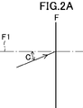
- the conditional expression (7) is an expression that specifies the light incident angle C with respect to the normal F1 of the bandpass filter surface F.
- the light incident angle C is defined in the same manner as the light incident angle B in FIG. 1, and the angle is represented by an absolute value, and all take positive values.
- the transmission spectrum shifts to the short wavelength side as the incident ray angle departs from 0 °. Therefore, by satisfying the conditional expression (7), the light incident angle with respect to the normal to the surface of the bandpass filter falls within an appropriate range, and the wavelength shift of the transmission spectrum can be suppressed.
- conditional expression (7) If the lower limit of conditional expression (7) is divided, that is, if the maximum incident angle of the light beam incident on the band-pass filter increases, the transmission spectrum shifts to the shorter wavelength side, and the transmittance at the used wavelength decreases, which is not preferable.
- the value exceeds the upper limit of the conditional expression (7) that is, the maximum incident angle of the light beam incident on the band-pass filter becomes too small, which means that the principal light beam and the upper and lower light beams are all arranged in a telecentric optical path arrangement. This makes it difficult to configure with the number of sheets, which is not preferable in terms of cost reduction.
- conditional expression (7) is more preferably 2.55, furthermore preferably 2.60, furthermore preferably 2.65, furthermore preferably 2.70, and 2.77. It is more preferable that there is.
- the upper limit of conditional expression (7) is preferably 15.00, more preferably 12.00, further preferably 8.00, and still more preferably 7.00.
- the light incident angle C is about 20 degrees. It is preferable not to dispose a bandpass filter closest to the image plane. In a wide-angle lens having a maximum angle of view exceeding 20 degrees, it is preferable not to dispose a bandpass filter closest to the object side.
- the lens optical system according to the eighth embodiment satisfies the following conditional expression. -0.09 ⁇ tan (D) ⁇ 0.27 (8)
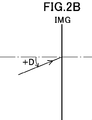
- D Angle on the meridional section formed by the principal ray of the most off-axis ray at a wavelength of N nm emitted from the most image-side surface of the lens optical system and incident on the image plane and a line parallel to the optical axis.
- the above conditional expression (8) is an expression that defines the angle at which the most off-axis ray in the lens optical system is incident on the image plane.
- the principal ray is a ray passing through the center of the stop among the off-axis rays at the wavelength Nnm.
- the light incident angle on the meridional section formed by the principal ray and a line parallel to the optical axis is positive in the direction shown in FIG. 2B.
- IMG represents an image plane.
- conditional expression (8) When the value exceeds the upper limit of the conditional expression (8), that is, the angle of the light beam incident on the image plane becomes too large, and the aperture ratio of the on-chip lens of the image pickup device is reduced, and the peripheral light amount is remarkably reduced, which is not preferable. Also, if the lower limit of conditional expression (8) is divided, that is, the angle of incidence on the image plane becomes small, it becomes difficult to reduce the diameter of the final lens, which is not preferable.
- conditional expression (8) is more preferably ⁇ 0.05, further preferably ⁇ 0.02, further preferably ⁇ 0.01, and still more preferably 0.00.
- the upper limit of conditional expression (8) is preferably 0.25, more preferably 0.22, further preferably 0.18, further preferably 0.15, and more preferably 0.12. And more preferably 0.08.
- the lens optical system according to the ninth embodiment is characterized in that the wavelength N is longer than 780 nm. Since the wavelength that can be sensed by human eyes is 400 nm to 750 nm, it is preferable to use a wavelength that cannot be sensed by human eyes in order to project a specific wavelength and receive the scattered light.
- the wavelength N is more preferably longer than 800 nm, further preferably longer than 830 nm, and further preferably longer than 850 nm.
- the lens optical system of the tenth embodiment is characterized by satisfying the following conditional expression. 0.10 ⁇ 1 / tan (
- Amin The minimum value of the angle between the tangent of the lens surface and the optical axis in all the lens surfaces included in the lens optical system.
- the conditional expression (9) is an expression that defines a tangent angle to the lens surface.
- the tangent angle A is represented by an absolute value, and all of the tangent angles take positive values. Therefore, the smaller the tangent angle, the stronger the surface inclination.
- the thickness error of the antireflection coat is reduced and the antireflection coat has an appropriate refractive power, which leads to a reduction in the number of lenses.
- the moldability of the surface is maintained.
- conditional expression (9) When the lower limit of conditional expression (9) is divided, that is, the inclination of the surface approaches a flat surface, the refractive power is weak, the overall length of the lens is increased, and a large number of lenses are required for aberration correction. It is not preferable because it is difficult to reduce the cost and cost.
- conditional expression (9) is more preferably 0.15, further preferably 0.25, further preferably 0.35, and still more preferably 0.50.
- the upper limit of conditional expression (9) is preferably 1.30, more preferably 1.28, further preferably 1.26, and still more preferably 1.20.
- the imaging apparatus includes an imaging device that converts an optical image formed by the lens optical system into an electric signal on an image side of the lens optical system.
- the configuration of the image sensor is not particularly limited, and a solid-state image sensor such as a CCD sensor or a CMOS sensor is exemplified.
- the imaging apparatus of the present invention has an image processing step of electrically processing image data captured by the image sensor to change the shape of the image data.
- image processing performed in the image processing process for example, image processing in which correction data for correcting distortion of an image shape is held, and the image data is corrected using the correction data, or the like is given.
- image processing in which correction data for correcting distortion of an image shape is held, and the image data is corrected using the correction data, or the like is given.
- miniaturizing an optical system including a lens distortion of the image shape becomes a problem, but by performing the image processing as described above, it is possible to form a distortion-free image and achieve miniaturization of the lens optical system. Is preferred.
- the negative refractive power of the lens disposed closest to the image can be increased, and miniaturization of the lens closest to the image can be achieved. Is preferred.
- the chromatic aberration of magnification is corrected by the image processing process, because the number of correction targets for optical aberration correction is reduced, the number of lenses is reduced, and the size of the lens optical system is reduced.
- An image sensor for converting an optical image formed by the optical system into an electric signal is provided on the image side of the lens optical system.
- the imaging device is not particularly limited, and a solid-state imaging device such as a CCD sensor or a CMOS sensor can be used.
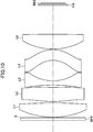
- FIG. 4 is a lens cross-sectional view showing the lens configuration of the lens optical system according to Example 1 of the present invention.
- the lens optical system according to the first embodiment uses a light beam having a wavelength N of 905 nm, and in order from the object side, a biconvex first lens L1 and an object-side convex meniscus shape having a positive refractive power on both surfaces.
- a second lens L2 having an aspheric surface, a third meniscus lens L3 having a negative refractive power and convex on the object side, a fourth lens L4 having a positive refractive power and a concave meniscus on the object side, It comprises a fifth meniscus lens L5 having a positive refractive power and convex on the object side, and a sixth lens L6 having a negative refractive power and a concave meniscus on the object side.
- a band-pass filter BPF is arranged on the object side of the lens L1 closest to the object.
- the aperture stop S is arranged on the image side of the band pass filter BPF closest to the object.
- the band-pass filter BPF has a wavelength range from 884 nm to 936 nm of a transmittance of 1% or more at an incident angle of 0 ° for a light beam having a wavelength N of 905 nm, and a transmittance range of half of the maximum transmittance, that is, a half-value width of 890 nm. 927 nm.
- the second lens L2 and the fourth lens L4 are resin lenses.
- All lenses have an anti-reflection coating on their lens surfaces.
- the object side surface of the fifth lens L5 is provided with an antireflection coating in which the wavelength at which the reflectance becomes the smallest in the wavelength range of N ⁇ 100 nm exists in the range of N ⁇ 50 nm.
- a layer containing MgF 2 as a material is provided on the air interface of the antireflection coat on the object side surface of the fifth lens L5, and the total number of layers is five.
- a layer containing SiO 2 as a material is provided, and the total number of layers is three.
- the band-pass filter BPF is disposed closest to the object side. Instead, the band-pass filter BPF based on a parallel plate is replaced by the fourth lens L4 and the fifth lens L5. , And Cmax in that case is 24.953 degrees.
- IMG indicates an image plane.
- the IMG specifically corresponds to an imaging surface of a solid-state imaging device such as a CCD sensor or a CMOS sensor.
- Table 1 is a specification table of the lens optical system.
- the specification table shows the focal length “f”, the F number “Fno.”, The half angle of view “ ⁇ ”, the image height “Y”, and the total optical length “TL” of the lens optical system at a wavelength of 905 nm.
- Table 1 f 30.658 Fno 1.095 ⁇ 12.000 Y 6.492 TL 49.917
- Table 2 shows the surface data of the lens optical system of the first example.
- surface number is the order of the lens surface counted from the object side
- r is the radius of curvature of the lens surface
- d is the distance between the lens surfaces on the optical axis
- ⁇ d indicates Abbe number for d-line
- H indicates effective radius.
- ASP displayed in the column next to the surface number indicates that the lens surface is aspheric
- S indicates an aperture stop.
- the units of length in each table are all “mm”, and the units of angle are all “°”.
- the radius of curvature “0” means a plane.
- the first and second surfaces in Table 2 are bandpass filters BPF, and the fifteenth and sixteenth surfaces are surface data of the cover glass CG.
- Table 2 Surface number r d Nd ⁇ d H 1 0.0000 1.100 1.50892 64.20 14.153 2 STOP 0.0000 0.200 14.000 3 30.7024 7.000 1.97213 29.13 14.858 4 -808.7238 0.200 14.348 5 ASP 32.5340 5.908 1.63641 20.37 13.770 6 ASP 40.7623 0.880 12.975 7 114.1620 1.700 1.55932 56.04 12.234 8 14.3799 10.423 10.342 9 ASP -11.3293 4.904 1.63641 20.37 10.321 10 ASP -13.0587 0.200 11.932 11 19.0455 7.900 1.92859 32.32 11.916 12 88.7164 2.862 10.357 13 -50.7286 1.600 1.55932 56.04 9.484 14 -400.0008 4.101 8.823 15 0.0000 0.400 1.508
- Table 3 shows the aspheric coefficient of each aspheric surface.
- the aspheric coefficient is a value when each aspheric shape is defined by the following equation.
- X (Y) CY 2 / [1+ ⁇ 1 ⁇ (1 + ⁇ ) ⁇ C 2 Y 2 ⁇ 1/2 ] + A4 ⁇ Y 4 + A6 ⁇ Y 6 + A8 ⁇ Y 8 + A10 ⁇ Y 10 + A12 ⁇ Y 12
- Ea indicates “ ⁇ 10 ⁇ a ”.
- Table 4 shows the focal length of each lens at a wavelength of 905 nm.
- Table 4 Lens surface number Focal length L1 3-4 30.553 L2 5-6 197.965 L3 7-8 -29.595 L4 9-1 1307.890 L5 11-12 24.765 L6 13-14 -104.040
- FIG. 5 shows a longitudinal aberration diagram of the lens optical system of the first example.
- the longitudinal aberration diagrams shown in each figure are spherical aberration (mm), astigmatism (mm), and distortion (%) in order from the left side in the drawings.
- the vertical axis indicates the ratio to the open F value
- the vertical axis is image height
- the horizontal axis is defocused
- the vertical axis represents image height
- Table 17 shows values of the conditional expressions (1) to (9) of the lens optical system of the first example.
- FIG. 6 is a lens cross-sectional view illustrating a lens configuration of a lens optical system according to Example 2.
- the lens optical system of the second example includes, in order from the object side, a biconvex first lens L1 and a second lens L2 having a positive refractive power and an object-side convex meniscus and having aspheric surfaces on both surfaces.
- a third lens L3 having a negative refractive power and an object-side convex meniscus shape
- a fourth lens L4 having a negative refractive power and an object-side concave meniscus
- It is composed of
- a band-pass filter BPF is arranged on the object side of the lens L1 closest to the object.
- the aperture stop S is arranged on the image side of the band pass filter BPF closest to the object.
- the bandpass filter BPF has a wavelength range of transmittance of 1% or more at an incident angle of 0 ° for light having a wavelength N of 905 nm from 884 nm to 936 nm, and a transmittance range that is half of the maximum transmittance, that is, a half width from 890 nm. 927 nm.
- the second lens L2 and the fourth lens L4 are resin lenses.
- All lenses have an anti-reflection coating on their lens surfaces.
- the object side surface of the fifth lens L5 is provided with an antireflection coating in which the wavelength at which the reflectance becomes the smallest in the wavelength range of N ⁇ 100 nm exists in the range of N ⁇ 50 nm.
- a layer containing MgF 2 as a material is provided on the air interface of the antireflection coat on the object side surface of the fifth lens L5, and the total number of layers is five.
- a layer containing SiO 2 as a material is provided on the air interface of the antireflection coat of the second lens L2 and the fourth lens L4, which are resin lenses, and the total number of layers is three.
- a band-pass filter BPF is disposed closest to the object side. Instead, a band whose parallel plate is a base between the fourth lens L4 and the fifth lens L5 is used.
- a pass filter BPF may be provided, in which case Cmax is 23.412 degrees.
- Table 5 is a table of specifications of the lens optical system of the second example. (Table 5) f 30.869 Fno 1.200 ⁇ 12.000 Y 6.561 TL 49.441
- Table 6 shows surface data of the lens optical system of the second example.
- the first and second surfaces in Table 6 are bandpass filters BPF, and the thirteenth and fourteenth surfaces are surface data of the cover glass CG.
- Table 6 Surface number r d Nd ⁇ d H 1 0.0000 1.100 1.50892 64.20 13.015 2 STOP 0.0000 0.200 12.862 3 30.4662 6.000 1.97213 29.13 13.584 4 -240.7561 0.100 13.238 5 ASP 38.3859 6.010 1.63641 20.37 12.735 6 ASP 95.0197 1.000 11.974 7 -73.0253 1.770 1.50892 64.20 11.588 8 12.3119 8.922 9.600 9 ASP -12.2585 4.550 1.63641 20.37 9.645 10 ASP -15.6370 0.200 11.678 11 33.2385 6.300 1.97213 29.13 13.585 12 -63.7223 12.207 13.384 13 0.0000 0.500 1.50892 64.17 6.96
- Table 7 shows the aspheric coefficient of each aspheric surface. (Table 7) 5 6 9 10 ⁇ 6.4527 55.5248 -1.2127 -0.6032 A4 -4.1920E-05 -7.1713E-05 -5.7922E-05 -1.3478E-05 A6 -2.2301E-07 -1.3274E-07 9.9430E-07 1.1139E-06 A8 7.1955E-10 1.2655E-09 1.7388E-09 -1.1537E-08 A10 -2.2983E-12 -7.2254E-12 -2.3641E-10 4.6508E-11 A12 -1.0660E-14 1.6334E-15 1.2423E-12 -8.8969E-14
- Table 8 shows the focal length of each lens at a wavelength of 905 nm.
- Table 8 Lens surface number Focal length L1 3-4 28.126 L2 5-6 97.187 L3 7-8 -20.558 L4 9-10 -187.190 L5 11-12 23.214
- FIG. 7 shows a longitudinal aberration diagram of the lens optical system of the second example.
- Table 17 shows values of the conditional expressions (1) to (9) of the second embodiment.
- FIG. 8 is a lens cross-sectional view illustrating a lens configuration of a lens optical system according to Example 3.
- the lens optical system of the third example includes, in order from the object side, a biconvex first lens L1 and a second lens L2 having a positive refractive power and an object-side convex meniscus shape and having aspheric surfaces on both surfaces.
- a third lens L3 having a negative refractive power and an object-side convex meniscus shape
- a fourth lens L4 having a negative refractive power and an object-side concave meniscus
- It is composed of
- a band-pass filter BPF is arranged on the object side of the lens L1 closest to the object.
- the aperture stop S is arranged on the image side of the band pass filter BPF closest to the object.
- the bandpass filter BPF has a wavelength range of transmittance of 1% or more at an incident angle of 0 ° for light having a wavelength N of 905 nm from 884 nm to 936 nm, and a transmittance range that is half of the maximum transmittance, that is, a half width from 890 nm. 927 nm.
- the second lens L2 and the fourth lens L4 are resin lenses.
- the lens surfaces of all the lenses are provided with an anti-reflection coating, and the object side surface of the fifth lens L5 is such that the wavelength at which the reflectance becomes the smallest in the wavelength range of N ⁇ 100 nm is in the range of N ⁇ 50 nm.
- An anti-reflection coating is present.
- a layer containing MgF 2 as a material is provided on the air interface of the antireflection coat on the object side surface of the fifth lens L5, and the total number of layers is five.
- a layer containing SiO 2 as a material is provided at the air interface of the antireflection coat of the second lens L2 and the fourth lens L4, which are resin lenses, and the total number of layers is three.
- band-pass filter BPF is disposed closest to the object, but instead, a band-pass filter BPF based on a parallel plate may be disposed between the fourth lens L4 and the fifth lens L5. Cmax in that case is 22.434 degrees.
- Table 9 is a table of specifications of the lens optical system of the third example. (Table 9) f 30.117 Fno 1.205 ⁇ 12.000 Y 6.402 TL 49.634
- Table 10 shows the surface data of the lens optical system.
- the first and second surfaces in Table 10 are bandpass filters BPF, and the thirteenth and fourteenth surfaces are surface data of the cover glass CG.
- Table 10 Surface number r d Nd ⁇ d H 1 0.0000 1.100 1.50892 64.20 12.653 2 STOP 0.0000 0.200 12.500 3 32.9134 6.000 1.97213 29.13 13.123 4 -251.5358 0.010 12.794 5 ASP 42.4007 6.010 1.63641 20.37 12.484 6 ASP 72.4349 1.000 11.761 7 -83.8728 1.770 1.50892 64.20 11.408 8 18.9014 9.359 10.153 9 ASP -8.9611 4.550 1.63641 20.37 10.108 10 ASP -12.2658 0.200 11.264 11 27.2871 6.300 1.97213 29.13 12.772 12 -136.7202 12.207 12.363 13 0.0000 0.500 1.50892 64.17 6.726 14 0.0000 0.429
- Table 11 shows the aspheric coefficient of each aspheric surface. (Table 11) 5 6 9 10 ⁇ 8.9071 29.6816 -0.8880 -0.1389 A4 -4.7241E-05 -9.2351E-05 -7.0871E-05 4.0736E-05 A6 -1.5948E-07 -1.6631E-07 6.0194E-07 7.0414E-07 A8 2.8786E-10 1.3382E-09 1.4888E-08 1.6059E-09 A10 -2.9428E-12 -7.7403E-12 -3.0849E-11 2.2175E-11 A12 -3.4823E-15 3.1449E-14 -3.0183E-13 -8.5723E-14
- Table 12 shows the focal length of each lens at a wavelength of 905 nm.
- Lens surface number Focal length L1 3-4 30.254 L2 5-6 149.080 L3 7-8 -30.135 L4 9-10 -112.507 L5 11-12 23.851
- FIG. 9 shows a longitudinal aberration diagram of the lens optical system of the third example.
- Table 17 shows values of the conditional expressions (1) to (9) of the third embodiment.
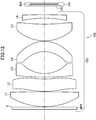
- FIG. 10 is a lens cross-sectional view illustrating a lens configuration of a lens optical system according to Example 4.
- the lens optical system of the second example includes, in order from the object side, a biconvex first lens L1 and a second lens L2 having a positive refractive power and an object-side convex meniscus and having aspheric surfaces on both surfaces.
- a third lens L3 having a negative refractive power and an object-side convex meniscus shape
- a fourth lens L4 having a negative refractive power and an object-side concave meniscus
- It is composed of
- a band-pass filter BPF is arranged on the object side of the lens L1 closest to the object.
- the aperture stop S is arranged on the image side of the band pass filter BPF closest to the object.
- the band-pass filter BPF has a wavelength range from 884 nm to 936 nm of a transmittance of 1% or more at an incident angle of 0 ° for a light beam having a wavelength N of 905 nm, and a transmittance range of half of the maximum transmittance, that is, a half-value width of 890 nm. 927 nm.
- the second lens L2 and the fourth lens L4 are resin lenses.
- All lenses have an anti-reflection coating on the lens surface.
- the object side surface of the fifth lens L5 is provided with an antireflection coating in which the wavelength at which the reflectance becomes the smallest in the wavelength range of N ⁇ 100 nm exists in the range of N ⁇ 50 nm.
- a layer containing MgF 2 as a material is provided on the air interface of the antireflection coat on the object side surface of the fifth lens L5, and the total number of layers is five.
- a layer containing SiO 2 as a material is provided on the air interface of the antireflection coat of the second lens L2 and the fourth lens L4, which are resin lenses, and the total number of layers is three.
- a band-pass filter BPF is disposed closest to the object side. Instead, a band whose base is a parallel flat plate between the fourth lens L4 and the fifth lens L5 is used.
- a pass filter BPF may be provided, in which case Cmax is 19.448 degrees.
- Table 13 is a table of specifications of the lens optical system of the fourth example. (Table 13) f 30.049 Fno 1.200 ⁇ 10.000 Y 5.297 TL 49.654
- Table 14 shows the surface data of the lens optical system of the fourth example.
- the first and second surfaces in Table 14 are bandpass filters BPF, and the thirteenth and fourteenth surfaces are surface data of the cover glass CG.
- Table 14 Surface number r d Nd ⁇ d H 1 0.0000 1.100 1.50892 64.20 12.627 2 STOP 0.0000 0.200 12.500 3 32.7400 6.000 1.97213 29.13 13.011 4 -234.0000 0.149 12.637 5 ASP 41.2130 6.010 1.63641 20.37 12.220 6 ASP 82.1802 1.000 11.434 7 -69.8000 1.770 1.50892 64.20 11.108 8 16.5500 9.126 9.676 9 ASP -8.8021 4.550 1.63641 20.37 9.644 10 ASP -11.4366 0.200 10.780 11 24.8000 6.300 1.97213 29.13 11.675 12 -800.0000 12.207 11.021 13 0.0000 0.500 1.50892 64.17 5.705 14 0.000
- Table 15 shows the aspheric coefficient of each aspheric surface. (Table 15) 5 6 9 10 ⁇ 8.2203 37.8603 -0.9723 -0.1843 A4 -4.8824E-05 -9.0205E-05 -6.8785E-05 3.7490E-05 A6 -1.5712E-07 -1.3562E-07 5.2603E-07 9.9278E-07 A8 3.8830E-10 1.4792E-09 1.3172E-08 -1.3622E-09 A10 -2.8759E-12 -7.3932E-12 -4.6550E-11 1.0841E-11 A12 -5.8433E-15 2.1091E-14 -3.4978E-14 1.1639E-13
- Table 16 shows the focal length of each lens at a wavelength of 905 nm.
- Lens surface number Focal length L1 3-4 29.876 L2 5-6 122.894 L3 7-8 -26.107 L4 9-10 -182.876 L5 11-12 24.838
- FIG. 11 shows a longitudinal aberration diagram of the lens optical system of the fourth example.
- Table 17 shows values of the conditional expressions (1) to (9) of the lens optical system of the fourth example.
- Table 17 shows the values of the conditional expressions (1) to (9) of the lens optical system of the fourth embodiment in addition to the first to third embodiments.
- Example 1 Example 2
- Example 3 Example 4 Conditional expression (1) fn / f -0.839 -0.784 -0.765 -0.813 Conditional expression (2) Y / f 0.212 0.213 0.213 0.176 Conditional expression (3)
- Conditional expression (6) 1 / tan (
- the imaging apparatus 100 includes a lens optical system 102 according to the present invention and a solid-state imaging device 104 disposed on an imaging plane IMG of the imaging optical system 102.
- the solid-state imaging device 104 has a cover glass CG.
- An image formed by the lens optical system 102 is converted into an image signal via the solid-state image sensor 104.
- the imaging signal is sent to a liquid crystal monitor (not shown) and displayed as an image.
Landscapes
- Physics & Mathematics (AREA)
- General Physics & Mathematics (AREA)
- Optics & Photonics (AREA)
- Health & Medical Sciences (AREA)
- Toxicology (AREA)
- Lenses (AREA)
- Optical Filters (AREA)
Applications Claiming Priority (2)
| Application Number | Priority Date | Filing Date | Title |
|---|---|---|---|
| JP2018-152725 | 2018-08-14 | ||
| JP2018152725A JP7100534B2 (ja) | 2018-08-14 | 2018-08-14 | レンズ光学系及び撮像装置 |
Publications (1)
| Publication Number | Publication Date |
|---|---|
| WO2020036032A1 true WO2020036032A1 (ja) | 2020-02-20 |
Family
ID=69525470
Family Applications (1)
| Application Number | Title | Priority Date | Filing Date |
|---|---|---|---|
| PCT/JP2019/027771 Ceased WO2020036032A1 (ja) | 2018-08-14 | 2019-07-12 | レンズ光学系及び撮像装置 |
Country Status (2)
| Country | Link |
|---|---|
| JP (1) | JP7100534B2 (https=) |
| WO (1) | WO2020036032A1 (https=) |
Cited By (1)
| Publication number | Priority date | Publication date | Assignee | Title |
|---|---|---|---|---|
| US12287458B2 (en) | 2020-09-18 | 2025-04-29 | Largan Precision Co., Ltd. | Electronic device |
Families Citing this family (1)
| Publication number | Priority date | Publication date | Assignee | Title |
|---|---|---|---|---|
| CN113156631B (zh) * | 2021-04-30 | 2024-08-02 | 中山联合光电科技股份有限公司 | 一种成像镜头及移动设备 |
Citations (6)
| Publication number | Priority date | Publication date | Assignee | Title |
|---|---|---|---|---|
| WO2013021659A1 (ja) * | 2011-08-11 | 2013-02-14 | 日立マクセル株式会社 | 赤外線用のレンズユニット、撮像モジュールおよび撮像装置 |
| US20140184880A1 (en) * | 2012-12-31 | 2014-07-03 | Kolen Co., Ltd. | Photographic Lens Optical System |
| JP2014167497A (ja) * | 2013-01-31 | 2014-09-11 | Hitachi Maxell Ltd | 赤外線用のレンズ装置 |
| US20150168680A1 (en) * | 2013-12-16 | 2015-06-18 | Sintai Optical (Shenzhen) Co., Ltd. | Near Infrared Lens Assembly |
| JP2018084704A (ja) * | 2016-11-24 | 2018-05-31 | コニカミノルタ株式会社 | 撮像レンズ、撮像レンズユニット及び撮像装置 |
| US20180172952A1 (en) * | 2016-12-15 | 2018-06-21 | Largan Precision Co., Ltd. | Optical photographing lens system, image capturing apparatus and electronic device |
Family Cites Families (7)
| Publication number | Priority date | Publication date | Assignee | Title |
|---|---|---|---|---|
| JPS53107824A (en) * | 1977-03-02 | 1978-09-20 | Canon Inc | Front focusing photographic lens |
| JPS5971014A (ja) * | 1982-10-15 | 1984-04-21 | Matsushita Electric Ind Co Ltd | 画像拡大投写用レンズ |
| JP2000330014A (ja) | 1999-05-25 | 2000-11-30 | Cosina Co Ltd | 大口径レンズ |
| JP2001281536A (ja) | 2000-03-28 | 2001-10-10 | Fuji Photo Optical Co Ltd | ガウス型レンズ |
| JP5966728B2 (ja) | 2012-07-30 | 2016-08-10 | リコーイメージング株式会社 | 大口径レンズ系 |
| EP2708929A3 (en) | 2012-09-14 | 2014-10-01 | Samsung Electro-Mechanics Co., Ltd | Imaging lens |
| JP6425238B2 (ja) | 2014-07-02 | 2018-11-21 | カンタツ株式会社 | 撮像レンズ |
-
2018
- 2018-08-14 JP JP2018152725A patent/JP7100534B2/ja active Active
-
2019
- 2019-07-12 WO PCT/JP2019/027771 patent/WO2020036032A1/ja not_active Ceased
Patent Citations (6)
| Publication number | Priority date | Publication date | Assignee | Title |
|---|---|---|---|---|
| WO2013021659A1 (ja) * | 2011-08-11 | 2013-02-14 | 日立マクセル株式会社 | 赤外線用のレンズユニット、撮像モジュールおよび撮像装置 |
| US20140184880A1 (en) * | 2012-12-31 | 2014-07-03 | Kolen Co., Ltd. | Photographic Lens Optical System |
| JP2014167497A (ja) * | 2013-01-31 | 2014-09-11 | Hitachi Maxell Ltd | 赤外線用のレンズ装置 |
| US20150168680A1 (en) * | 2013-12-16 | 2015-06-18 | Sintai Optical (Shenzhen) Co., Ltd. | Near Infrared Lens Assembly |
| JP2018084704A (ja) * | 2016-11-24 | 2018-05-31 | コニカミノルタ株式会社 | 撮像レンズ、撮像レンズユニット及び撮像装置 |
| US20180172952A1 (en) * | 2016-12-15 | 2018-06-21 | Largan Precision Co., Ltd. | Optical photographing lens system, image capturing apparatus and electronic device |
Cited By (1)
| Publication number | Priority date | Publication date | Assignee | Title |
|---|---|---|---|---|
| US12287458B2 (en) | 2020-09-18 | 2025-04-29 | Largan Precision Co., Ltd. | Electronic device |
Also Published As
| Publication number | Publication date |
|---|---|
| JP7100534B2 (ja) | 2022-07-13 |
| JP2020027206A (ja) | 2020-02-20 |
Similar Documents
| Publication | Publication Date | Title |
|---|---|---|
| US10877244B1 (en) | Optical photographing system and electronic device | |
| CN107255856B (zh) | 摄像光学镜组、取像装置以及车用摄影装置 | |
| US9348117B1 (en) | Photographing optical lens assembly, image capturing unit and electronic device | |
| JP6205034B2 (ja) | 撮像レンズ系及びこれを備えた撮像装置 | |
| US8441745B2 (en) | Optical lens assembly for image taking | |
| TWI484247B (zh) | 攝像裝置與其光學成像鏡頭 | |
| TWI475246B (zh) | 具濾光元件之光學取像鏡頭 | |
| TWI435138B (zh) | 影像拾取光學系統 | |
| JP4977869B2 (ja) | 撮像レンズ、撮像装置及び携帯端末 | |
| US20130021678A1 (en) | Photographing optical lens assembly | |
| US7626768B2 (en) | Zoom lens and camera with zoom lens | |
| US9304304B2 (en) | Image capturing lens assembly | |
| US8477433B2 (en) | Optical imaging lens assembly | |
| US20200249433A1 (en) | Electronic device | |
| CN110488469B (zh) | 一种光学镜头及电子设备 | |
| CN102681144A (zh) | 摄像用光学镜片组 | |
| TWI443405B (zh) | 影像擷取光學系統 | |
| WO2016110883A1 (ja) | 撮像レンズおよび撮像装置 | |
| US9122038B2 (en) | Imaging lens and imaging apparatus | |
| CN112764201B (zh) | 光学系统、摄像模组及电子设备 | |
| US10401544B2 (en) | Optical system and optical apparatus including the same | |
| US8390944B2 (en) | Photographing optical lens assembly | |
| CN201917706U (zh) | 摄像透镜以及摄像装置 | |
| JP7178821B2 (ja) | 撮像光学系及び撮像装置 | |
| WO2020036032A1 (ja) | レンズ光学系及び撮像装置 |
Legal Events
| Date | Code | Title | Description |
|---|---|---|---|
| 121 | Ep: the epo has been informed by wipo that ep was designated in this application |
Ref document number: 19850264 Country of ref document: EP Kind code of ref document: A1 |
|
| NENP | Non-entry into the national phase |
Ref country code: DE |
|
| 122 | Ep: pct application non-entry in european phase |
Ref document number: 19850264 Country of ref document: EP Kind code of ref document: A1 |