WO2020035945A1 - フリークーリングユニット - Google Patents
フリークーリングユニット Download PDFInfo
- Publication number
- WO2020035945A1 WO2020035945A1 PCT/JP2018/030536 JP2018030536W WO2020035945A1 WO 2020035945 A1 WO2020035945 A1 WO 2020035945A1 JP 2018030536 W JP2018030536 W JP 2018030536W WO 2020035945 A1 WO2020035945 A1 WO 2020035945A1
- Authority
- WO
- WIPO (PCT)
- Prior art keywords
- heat exchanger
- air heat
- free cooling
- cooling unit
- machine room
- Prior art date
- Legal status (The legal status is an assumption and is not a legal conclusion. Google has not performed a legal analysis and makes no representation as to the accuracy of the status listed.)
- Ceased
Links
Images


Classifications
-
- F—MECHANICAL ENGINEERING; LIGHTING; HEATING; WEAPONS; BLASTING
- F28—HEAT EXCHANGE IN GENERAL
- F28D—HEAT-EXCHANGE APPARATUS, NOT PROVIDED FOR IN ANOTHER SUBCLASS, IN WHICH THE HEAT-EXCHANGE MEDIA DO NOT COME INTO DIRECT CONTACT
- F28D1/00—Heat-exchange apparatus having stationary conduit assemblies for one heat-exchange medium only, the media being in contact with different sides of the conduit wall, in which the other heat-exchange medium is a large body of fluid, e.g. domestic or motor car radiators
- F28D1/02—Heat-exchange apparatus having stationary conduit assemblies for one heat-exchange medium only, the media being in contact with different sides of the conduit wall, in which the other heat-exchange medium is a large body of fluid, e.g. domestic or motor car radiators with heat-exchange conduits immersed in the body of fluid
- F28D1/04—Heat-exchange apparatus having stationary conduit assemblies for one heat-exchange medium only, the media being in contact with different sides of the conduit wall, in which the other heat-exchange medium is a large body of fluid, e.g. domestic or motor car radiators with heat-exchange conduits immersed in the body of fluid with tubular conduits
Definitions
- the present invention relates to a free cooling unit having a free cooling circuit for circulating a heat medium.
- a free cooling system that uses a cooling tower as a heat source without using a refrigerator when the outside air temperature is low in winter has been known.
- air conditioning is required throughout the year regardless of day and night to process heat radiation from production equipment.
- both a refrigerator for producing cold water for cooling indoor air and a cooling tower for producing cold water for releasing exhaust heat from the refrigerator to the atmosphere have been operated year-round.
- the temperature of the cold water from the cooling tower also decreases.
- the free cooling system supplies cold water from the cooling tower directly to the load side, and does not use a refrigerator. Therefore, the free cooling system is an effective energy saving system for buildings and the like that require annual cooling.
- Patent Document 1 discloses a cooling tower having a cylindrical casing. Inside the casing, there are provided an axial blower, a drive motor for the axial blower, a sprinkler, and a heat exchange filler. An intake port is formed on a side surface of the casing.
- the present invention has been made to solve the above-described problems, and even when a plurality of units are installed close to each other, a work space for performing maintenance or the like can be secured, and pressure loss can be suppressed. And a free cooling unit.
- the free cooling unit according to the present invention is a free cooling unit having an air heat exchanger, a cooling heat exchanger, and a pump connected by piping and having a free cooling circuit for circulating a heat medium in the piping.
- An air heat exchanger chamber disposed at an upper portion, and a machine room disposed at a lower portion, wherein the air heat exchanger chamber has a pair of flat plate-like air heat exchangers.
- An air heat exchanger at least one of which is provided so as to be inclined inward, and is configured so that an interval becomes narrower toward the machine room when viewed from the front, and when viewed from the front.
- the width of the upper end of the machine room is smaller than the width of the upper end of the air heat exchanger room.
- one opposing side surface of the air heat exchanger chamber is constituted by a pair of flat air heat exchangers, and at least one of the air heat exchangers is inclined inward.
- the space is formed so as to be narrower toward the machine room when viewed from the front, so that a space extending downward is formed on the outer surface side of the air heat exchanger room.
- the width of the upper end of the machine room when viewed from the front is smaller than the width of the upper end of the air heat exchanger room, a space is formed on the outer surface side of the machine room.
- the free cooling unit is a work space for maintenance and the like, so even if multiple units are installed close to each other, a work space can be secured, and the work space improves the air intake volume by the blower. Therefore, pressure loss can also be suppressed.
- FIG. 1 is a schematic configuration diagram of a free cooling system having a free cooling unit according to Embodiment 1 of the present invention. It is the front view which showed typically the free cooling unit which concerns on Embodiment 1 of this invention.
- FIG. 2 is an internal configuration diagram schematically showing a free cooling unit according to Embodiment 1 of the present invention in plan view.
- FIG. 3 is an enlarged view showing a free cooling unit according to Embodiment 1 of the present invention, showing a main part of an indoor heat exchanger.
- Fig. 4 Fig. 4 is an enlarged view showing a free cooling unit according to Embodiment 1 of the present invention, showing a different form of a main part of the indoor heat exchanger.
- FIG. 1 is a schematic configuration diagram of a free cooling system having a free cooling unit according to Embodiment 1 of the present invention. It is the front view which showed typically the free cooling unit which concerns on Embodiment 1 of this invention.
- FIG. 2 is an internal configuration diagram schematically showing a
- Embodiment 2 is a plan view schematically showing a free cooling unit according to Embodiment 1 of the present invention, which has a configuration having a plurality of blowers. It is the front view which showed typically the free cooling unit which concerns on Embodiment 2 of this invention. It is the front view which showed typically the free cooling unit which concerns on Embodiment 3 of this invention.
- FIG. 1 is a schematic configuration diagram of a free cooling system having a free cooling unit according to Embodiment 1 of the present invention.
- the free cooling unit 1 has a free cooling circuit 10, and constitutes a free cooling system 100 together with the chiller unit 2 having a refrigerant circuit 20.
- This free cooling unit 1 is configured as a substitute for a conventional cooling tower.
- the free cooling system 100 the liquid heat medium circulating in the pipe 15 of the free cooling circuit 10 and the refrigerant circulating in the pipe 26 of the refrigerant circuit 20 flow through the water pipe 30 of the water circuit 3 through the water pump 31.
- This is a configuration in which heat is exchanged with cold water circulated by driving to cool the cold water.
- the free cooling system 100 shown in FIG. 1 is configured such that the flow of the heat medium and the flow of the chilled water are countercurrent, and the flow of the refrigerant and the flow of the chilled water are counterflow. This is because by making these flows counterflow, the temperature difference increases and the heat exchange rate increases.
- the flow of the refrigerant and the flow of the cold water may be a parallel flow.
- the free cooling circuit 10 is arranged on the upstream side with respect to the flow of cold water, and the refrigerant circuit 20 is arranged on the downstream side.
- a first air heat exchanger 11, a heat source side of a water heat exchanger as a first cooling heat exchanger 12, and a brine pump 14 are connected by a pipe 15.
- brine is circulated in the pipe 15 as a liquid heat medium.
- the liquid heat medium may be water or the like in addition to brine.
- the free cooling circuit 10 is controlled by the control device 16.
- the first air heat exchanger 11 is a fin-and-tube heat exchanger including a heat transfer tube and a number of fins.
- the first air heat exchanger 11 exchanges heat between the brine supplied to the first air heat exchanger 11 and the air passing through the first air heat exchanger 11 by blowing air from the first blower 17. Let cool.
- the header 11b of the first air heat exchanger 11 has an air vent 11a.
- the first blower 17 has a function of sucking outside air into the free cooling unit 1 and blowing out the sucked outside air to the outside, and is configured by, for example, a propeller fan or the like.
- the first blower 17 is driven by a blower motor 17a.
- the first cooling heat exchanger 12 is a plate-type heat exchanger that exchanges heat between brine flowing in the plate and cold water in the water circuit 3 flowing in the plate.
- the first cooling heat exchanger 12 exchanges heat between the brine supplied to the first cooling heat exchanger 12 and cold water circulating in the water circuit 3 to cool the cold water.
- the brine pump 14 is provided to circulate the brine.
- the free cooling circuit 10 may include an expansion tank that absorbs the brine that has expanded due to a rise in temperature.
- the expansion tank is constituted by, for example, a closed type expansion tank or the like, and is arranged upstream or downstream of the brine pump 14.
- a bypass circuit 15 a that connects the upstream side and the downstream side of the first cooling heat exchanger 12 is provided.
- the bypass circuit 15a is provided with a valve 15b.
- the bypass circuit 15a and the valve 15b are provided to improve the partial load efficiency in the partial load operation.
- the free cooling circuit 10 may have a configuration in which the bypass circuit 15a and the valve 15b are omitted.
- the free cooling unit 1 is provided with at least one water temperature detection sensor for detecting the temperature of cold water and at least one outside air temperature detection sensor for detecting the outside air temperature.
- the water temperature detection sensor and the outside air temperature detection sensor are composed of, for example, a thermistor.
- the free cooling unit 1 may be provided with a flow meter for detecting the flow rate of the cold water.
- the control device 16 controls the number of rotations of the brine pump 14 to adjust the flow rate of the brine or controls the blower motor 17a based on, for example, the detection values detected by the above sensors and the flow meter. 17 is driven to rotate.
- the control device 16 includes an arithmetic device such as a microcomputer or a CPU, and software executed on the arithmetic device. Note that the control device 16 may be configured by hardware such as a circuit device that realizes the function.
- the refrigerant circuit 20 includes a compressor 21, a second air heat exchanger 22, an expansion mechanism 23, a heat source side of a water heat exchanger as a second cooling heat exchanger 24, and an accumulator. 25 are connected by a pipe 26, and the refrigerant circulates through the pipe 26.
- the refrigerant circuit 20 is controlled by the control device 27.
- the compressor 21 compresses the sucked refrigerant, discharges it in a state of high temperature and high pressure.
- the compressor 21 has a configuration in which the operating capacity (frequency) can be varied, and uses, for example, a positive displacement compressor driven by a motor controlled by an inverter.
- the second air heat exchanger 22 functions as a condenser, and is, for example, a fin and tube heat exchanger including a heat transfer tube and a number of fins.
- the second air heat exchanger 22 exchanges the refrigerant discharged from the compressor 21 and supplied to the second air heat exchanger 22 with the air passing through the second air heat exchanger 22 due to the blowing of the second blower 28.
- the refrigerant is cooled by heat exchange.
- the second blower 28 has a function of sucking outside air into the chiller unit 2 and blowing out the sucked outside air to the outside, and is configured by, for example, a propeller fan or the like.
- the second blower 28 is driven by a blower motor 28a.
- the expansion mechanism 23 is for decompressing and expanding the refrigerant flowing in the refrigerant circuit 20 and is constituted by, for example, an electronic expansion valve whose opening is variably controlled.
- the second cooling heat exchanger 24 functions as an evaporator, and is, for example, a plate-type heat exchanger that exchanges heat between a refrigerant flowing in the plate and cold water in the water circuit 3 flowing in the plate.
- the second cooling heat exchanger 24 exchanges heat between the refrigerant supplied to the second cooling heat exchanger 24 and cold water circulating in the water circuit 3 to cool the cold water.
- the accumulator 25 stores the refrigerant flowing out of the second cooling heat exchanger 24.
- the operation of the free cooling unit 1 is stopped and only the chiller unit 2 is operated. That is, the refrigerant circulating through the refrigerant circuit 20 and the chilled water circulating through the water circuit 3 exchange heat, thereby cooling the chilled water.
- the free cooling system 100 operates both the chiller unit 2 and the free cooling unit 1 in, for example, an intermediate period. That is, the refrigerant circulating in the refrigerant circuit 20 and the chilled water circulating in the water circuit 3 exchange heat, and the brine circulating in the free cooling circuit 10 and chilled water circulating in the water circuit 3 exchange heat. Then, the cold water is cooled. As described above, by using a hybrid system that operates both the chiller unit 2 and the free cooling unit 1, the load on the refrigerant circuit 20 can be reduced, and the operation efficiency can be improved.
- the free cooling system 100 stops the chiller unit 2 and operates only the free cooling unit 1 in winter, for example.
- the cold water is cooled by performing heat exchange between the brine circulating in the free cooling circuit 10 and the cold water circulating in the water circuit 3.
- super-efficient operation can be performed, and energy saving can be realized.
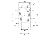
- FIG. 2 is a front view schematically showing the free cooling unit according to Embodiment 1 of the present invention.
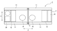
- FIG. 3 is an internal configuration diagram in plan view schematically showing the free cooling unit according to Embodiment 1 of the present invention.
- the free cooling unit 1 includes an air heat exchanger room A disposed at an upper portion and a machine room B disposed at a lower portion.
- a first air heat exchanger 11, a first blower 17, and a blower motor 17a are provided in the air heat exchanger room A.
- an exhaust port 6 for sucked outside air.
- an outside air temperature sensor for detecting the outside air temperature is provided outside the housing of the free cooling unit 1.
- One side of the air heat exchanger chamber A is constituted by a pair of flat first air heat exchangers 11.
- Each of the first air heat exchangers 11 is provided so as to be inclined inward, and is configured such that an interval becomes narrower toward the machine room B when viewed from the front. Therefore, the width dimension W2 of the lower end of the air heat exchanger chamber A is smaller than the width dimension W1 of the upper end of the air heat exchanger chamber A. Therefore, a space S1 extending downward is formed on the outer surface side of the air heat exchanger room A.
- the front view in the first embodiment refers to a state in which the free cooling unit 1 is viewed from the lateral direction X.
- FIG. 4 is an enlarged view of a free cooling unit according to Embodiment 1 of the present invention, showing a main part of the indoor heat exchanger.
- FIG. 5 is an enlarged view of a free cooling unit according to Embodiment 1 of the present invention, showing a different form of a main part of the indoor heat exchanger.
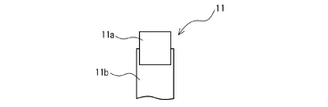
- an air vent 11 a for venting air from the heat transfer tube is provided at the upper end of the first air heat exchanger 11.
- the air vent 11a is provided so as to protrude upward from the upper end of the header 11b, so that air can be vented to the top of the first air heat exchanger 11.
- the air vent portion 11a is provided so as to protrude laterally at the upper end portion of the header 11b, so that contact with, for example, a sheet metal or the like located above the header 11b can be avoided. .
- the machine room B includes a first cooling heat exchanger 12, a brine pump 14, a power supply box 18, a control box 13, and a water circuit inside a rectangular parallelepiped casing 7.
- 3 water pipes 30 are provided.
- the width dimension W3 of the casing 7 when viewed from the front is substantially the same as the width dimension W2 of the lower end portion of the air heat exchanger chamber A. That is, the width W3 of the upper end of the machine room B in front view is smaller than the width W1 of the upper end of the air heat exchanger room A. Therefore, a space S2 is formed on the outer surface side of the machine room B.
- the power supply box 18 contains a power supply device.
- the control box 13 has a built-in control device 16 for controlling the free cooling circuit 10. Further, a water pump 31 for circulating cold water in the water circuit 3 may be provided in the machine room B.
- a space S1 formed on the outer surface side of the air heat exchanger room A and extending downward and a space S2 formed on the outer surface side of the machine room B are: This is a work space for performing maintenance and the like.
- the width W3 of the upper end of the machine room B may be smaller than the width W1 of the upper end of the air heat exchanger A, and is not limited to the illustrated form.
- the drain pan 4 catches rainwater or the like that has entered the air heat exchanger room A, and it is possible to suppress the situation where rainwater enters the machine room B. Therefore, it is possible to prevent electric leakage and to prevent rust and the like of various components. This is because it can be suppressed. Further, by providing the drain pan 4, the heat insulating effect of the machine room B can be enhanced.
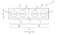
- FIG. 6 is a plan view schematically showing a free cooling unit according to Embodiment 1 of the present invention, which has a configuration having a plurality of blowers.
- the free cooling unit 1 shown in FIG. 6 has a configuration including four first blowers 17.
- the air heat exchanger room A is divided into a first air heat exchanger room A1 and a second air heat exchanger room A2 with an intermediate portion partitioned by a partition plate 5.
- first air heat exchanger room A1 and the second air heat exchanger room A2 two rows of the first air heat exchanger 11 and two first blowers 17 are arranged, respectively.
- the free cooling unit 1 by providing the partition plate 5 to partition the air heat exchanger room A, it is possible to suppress a situation in which the plurality of first blowers 17 inhale outside air with each other, and to improve performance. .
- positioned the 1st blower 17 by 2 was shown, you may divide into three or more.
- the free cooling unit 1 includes an air heat exchanger room A arranged at an upper part and a machine room B arranged at a lower part.
- the air heat exchanger chamber A has a pair of flat first air heat exchangers 11 on one side surface.
- Each of the first air heat exchangers 11 is provided so as to be inclined inward, and is configured such that an interval becomes narrower toward the machine room B when viewed from the front. Therefore, a space S1 extending downward is formed on the outer surface side of the air heat exchanger room A.
- the width dimension W3 of the upper end of the machine room B when viewed from the front is smaller than the width dimension W1 of the upper end of the air heat exchanger chamber A. Therefore, a space S2 is formed on the outer surface side of the machine room B.
- the free cooling unit 1 includes a space S1 formed on the outer surface side of the air heat exchanger room A and extending downward, and a space S2 formed on the outer surface side of the machine room B. Is a work space for maintenance and the like, so that even if a plurality of units are installed close to each other, a work space can be secured, and the work space increases the amount of air sucked by the blower, so that pressure loss can be suppressed.
- the free cooling unit 1 is formed of a rectangular parallelepiped casing 7 in which the machine room B houses constituent members. Therefore, the free cooling unit 1 can form a sufficient space S2 on the outer surface side of the machine room B, while securing a space for storing the constituent members in the machine room B.
- the free cooling unit 1 can receive the rainwater or the like that has entered the air heat exchanger room A with the drain pan 4 and can suppress the situation where the rainwater enters the machine room B, so that the electric leakage can be prevented. Also, rust and the like of various constituent members can be suppressed.
- the free cooling unit 1 can also enhance the heat insulating effect of the machine room B by the drain pan 4.
- the free cooling unit 1 has a plurality of sections in which the air heat exchanger chamber A is partitioned by the partition plate 5. Each section is provided with a first air heat exchanger 11, a first blower 17, and a blower motor 17a. Therefore, the free cooling unit 1 can suppress the situation where the plurality of first blowers 17 inhale the outside air with each other, and can improve the performance. Further, the free cooling unit 1 can drive the partitioned first blower 17 in accordance with the required cooling capacity, so that waste of power can be reduced and the energy saving effect can be enhanced.
- an air vent 11a is provided. Therefore, in the free cooling unit 1, air can be released to the uppermost stage of the first air heat exchanger 11, and the effect of suppressing air biting and the like can be enhanced.
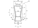
- FIG. 7 is a front view schematically showing a free cooling unit according to Embodiment 2 of the present invention.
- the same components as those of the free cooling unit 1 described in the first embodiment are denoted by the same reference numerals, and description thereof will be omitted as appropriate.
- the air heat exchanger chamber A of the free cooling unit 1A also includes one pair of flat air heat exchangers 11 on one side.
- Each of the first air heat exchangers 11 is provided so as to be inclined inward, and is configured such that an interval becomes narrower toward the machine room B when viewed from the front. Therefore, the width dimension W2 of the lower end of the air heat exchanger chamber A is smaller than the width dimension W1 of the upper end of the air heat exchanger chamber A. Therefore, a space S1 extending downward is formed on the outer surface side of the air heat exchanger room A.
- the machine room B is composed of a casing 8 having a trapezoidal shape when viewed from the front.
- the side surface of the free cooling unit 1A is formed in a lateral V-shape by the leg 8a of the casing 8 and the inclined first air heat exchanger 11. More specifically, the width dimension W3 of the upper end of the casing 8 in a front view is substantially the same as the width dimension W2 of the lower end of the air heat exchanger chamber A. That is, the width W3 of the upper end of the machine room B in front view is smaller than the width W1 of the upper end of the air heat exchanger room A.
- the width dimension W4 of the lower end of the machine room B when viewed from the front is smaller than the width dimension W1 of the upper end of the air heat exchanger chamber A. Therefore, a space S2 is formed on the outer surface side of the machine room B.
- the width W3 of the upper end of the machine room B may be smaller than the width W1 of the upper end of the air heat exchanger A, and is not limited to the illustrated form.
- the trapezoidal casing 8 is not limited to the configuration in which the left and right legs 8a are inclined, and may have, for example, a configuration in which one leg 8a is vertical. Other configurations are the same as those of the free cooling unit 1 of the first embodiment.
- the free cooling unit 1A according to the second embodiment also includes a space S1 formed on the outer surface side of the first air heat exchanger 11 and extending downward, and a space S2 formed on the outer surface side of the machine room B.
- a space S1 formed on the outer surface side of the first air heat exchanger 11 and extending downward
- a space S2 formed on the outer surface side of the machine room B. Therefore, even when a plurality of free cooling units 1A are arranged close to each other, a work space can be secured, and the work space increases the amount of air sucked by the first blower 17, so that pressure loss can be suppressed. .
- the casing 8 of the free cooling unit 1A has a trapezoidal shape, the storage space of the machine room B can be widened, and the layout design of the components housed in the machine room B becomes easy.
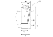
- FIG. 8 is a front view schematically showing a free cooling unit according to Embodiment 3 of the present invention.
- the same components as those of the free cooling unit 1 described in the first embodiment are denoted by the same reference numerals, and description thereof will be omitted as appropriate.
- the air heat exchanger chamber A of the free cooling unit 1B according to the third embodiment also includes one pair of flat first air heat exchangers 11 on opposite sides.
- One of the first air heat exchangers 11 is provided so as to be inclined inward, and the other is provided vertically toward the machine room B, so that an interval becomes narrower toward the machine room B when viewed from the front. It is configured. Therefore, the width dimension W2 of the lower end of the air heat exchanger chamber A is smaller than the width dimension W1 of the upper end of the air heat exchanger chamber A. Therefore, a space S1 extending downward is formed on one outer surface side of the air heat exchanger chamber A.
- the machine room B is composed of a rectangular parallelepiped casing 7.
- the width dimension W3 of the casing 7 when viewed from the front is substantially the same as the width dimension W2 of the lower end portion of the air heat exchanger chamber A. That is, the width W3 of the upper end of the machine room B in front view is smaller than the width W1 of the upper end of the air heat exchanger room A. Therefore, a space S2 is formed on one outer surface side of the machine room B.
- the width W3 of the upper end of the machine room B may be smaller than the width W1 of the upper end of the air heat exchanger A, and is not limited to the illustrated form.
- the free cooling unit 1B according to the third embodiment is formed on the space S1 formed on one outer surface side of the air heat exchanger room A and extending downward, and on the one outer surface side of the machine room B.
- the space S2 is a work space for performing maintenance and the like. Therefore, even if a plurality of free cooling units 1B are arranged close to each other, a work space can be secured, and the work space increases the amount of air sucked by the first blower 17, so that pressure loss can be suppressed. .
- the free cooling unit 1B according to the third embodiment is suitable as a unit located at both ends when a plurality of units are arranged, and is suitable when a work space only needs to be secured on one side surface.
- the trapezoidal casing 8 as viewed in the front view described in the second embodiment may be used.
- the side surface of the free cooling unit 1B is formed in a lateral V-shape by the leg 8a of the one casing 8 and the inclined first air heat exchanger 11.
- the present invention has been described based on the embodiment, the present invention is not limited to the configuration of the above embodiment.
- the free cooling unit 1 is not limited to being used in the free cooling system 100 described above, and may be used as a cooling tower by connecting only the free cooling circuit 10, for example.
- the free cooling unit 1 is not limited to the contents described above, and may include other components.
- the casing 7 or 8 constituting the machine room B is not limited to a rectangular parallelepiped shape or a trapezoidal shape, and may have another shape.
- the liquid flowing through the water pipe 30 in the water circuit 3 is not limited to cold water, and may be another liquid.
- the present invention includes a range of design changes and application variations usually performed by those skilled in the art without departing from the technical idea thereof.
Landscapes
- Engineering & Computer Science (AREA)
- Physics & Mathematics (AREA)
- Thermal Sciences (AREA)
- Mechanical Engineering (AREA)
- General Engineering & Computer Science (AREA)
- Other Air-Conditioning Systems (AREA)
- Heat-Exchange Devices With Radiators And Conduit Assemblies (AREA)
Abstract
フリークーリングユニットは、空気熱交換器と、冷却熱交換器と、ポンプと、が配管で接続され、配管内に熱媒体を循環させるフリークーリング回路を有している。フリークーリングユニットは、上部に配置された空気熱交換器室と、下部に配置された機械室と、を備えている。空気熱交換器室は、一の対向する側面が、一対の平板状の空気熱交換器で構成されている。空気熱交換器は、少なくとも一方が内方に傾斜させて設けられ、正面視において機械室に向かって間隔が狭くなるように構成されている。正面視における機械室の上端部の幅寸法は、空気熱交換器室の上端部の幅寸法よりも小さい。
Description
本発明は、熱媒体を循環させるフリークーリング回路を備えたフリークーリングユニットに関するものである。
従来、冬期において外気温が低いときに、冷凍機を使用せず冷却塔を熱源として利用するフリークーリングシステムが知られている。例えば工場等では、生産機器からの放熱を処理するために、年間を通じて昼夜問わず冷房が必要である。このような場合に、室内の空気を冷やすための冷水を製造する冷凍機と、冷凍機からの排熱を大気に放出するための冷水を製造する冷却塔の両方を年中運転していた。しかし、外気温度が低いときは、冷却塔からの冷水温度も低下する。フリークーリングシステムでは、冷却塔からの冷水を直接負荷側に供給し、冷凍機を使用しないので、年間冷房が必要な建物等に効果的な省エネルギーシステムである。
例えば特許文献1では、円筒形状のケーシングを有する冷却塔が開示されている。ケーシングの内部には、軸流送風翼車、軸流送風翼車の駆動用モータ、散水装置及び熱交換用充填物等が設けられている。ケーシングの側面には、吸気口が形成されている。
特許文献1に開示された冷却塔では、ケーシングが円筒形状で構成されているため、複数台を近接させて設置すると、隣接する冷却塔を連結するための作業及びメンテナンス等を行うための作業スペースを確保できない。また、吸気口が近接して対向し、互いに空気を吸い合うので、軸流送風翼車による吸い込み風量が低下し、圧力損失が大きくなる。そのため、このような冷却塔では、作業スペースを十分に確保でき、且つ圧力損失を低減させるための間隔をあけて設置する必要がある。しかし、限られた設置スペースに間隔を考慮して冷却塔を設置するとなると、配置設計が困難となるし、設置台数も制限される。
本発明は、上記のような課題を解決するためになされたものであり、複数台を近接させて設置しても、メンテナンス等を行う作業スペースを確保することができ、且つ圧力損失も抑制できる、フリークーリングユニットを提供することを目的とする。
本発明に係るフリークーリングユニットは、空気熱交換器と、冷却熱交換器と、ポンプと、が配管で接続され、当該配管内に熱媒体を循環させるフリークーリング回路を有するフリークーリングユニットであって、上部に配置された空気熱交換器室と、下部に配置された機械室と、を備えており、前記空気熱交換器室は、一の対向する側面が、一対の平板状の前記空気熱交換器で構成されており、前記空気熱交換器は、少なくとも一方が内方に傾斜させて設けられ、正面視において前記機械室に向かって間隔が狭くなるように構成されており、正面視における前記機械室の上端部の幅寸法は、前記空気熱交換器室の上端部の幅寸法よりも小さい。
本発明に係るフリークーリングユニットは、空気熱交換器室の一の対向する側面が、一対の平板状の空気熱交換器で構成されており、空気熱交換器の少なくとも一方が内方に傾斜させて設けられ、正面視において機械室に向かって間隔が狭くなるように構成されているので、空気熱交換器室の外面側に下方に向かって拡がる空間が形成される。また、正面視における機械室の上端部の幅寸法が、空気熱交換器室の上端部の幅寸法よりも小さいので、機械室の外面側に空間が形成される。つまり、フリークーリングユニットは、当該空間がメンテナンス等を行うための作業スペースとなるので、複数台を近接させて設置しても、作業スペースを確保でき、且つその作業スペースによって送風機による吸い込み風量が向上するので、圧力損失も抑制できる。
以下、図面を参照して、本発明の実施の形態について説明する。なお、各図中、同一又は相当する部分には、同一符号を付して、その説明を適宜省略又は簡略化する。また、各図に記載の構成について、その形状、大きさ、及び配置等は、本発明の範囲内で適宜変更することができる。
実施の形態1.
図1は、本発明の実施の形態1に係るフリークーリングユニットを有するフリークーリングシステムの概略構成図である。フリークーリングユニット1は、図1に示すように、フリークーリング回路10を有しており、冷媒回路20を有するチラーユニット2と共に、フリークーリングシステム100を構成するものである。このフリークーリングユニット1は、従来の冷却塔の代替品として構成されたものである。
図1は、本発明の実施の形態1に係るフリークーリングユニットを有するフリークーリングシステムの概略構成図である。フリークーリングユニット1は、図1に示すように、フリークーリング回路10を有しており、冷媒回路20を有するチラーユニット2と共に、フリークーリングシステム100を構成するものである。このフリークーリングユニット1は、従来の冷却塔の代替品として構成されたものである。
フリークーリングシステム100は、フリークーリング回路10の配管15内を循環する液状の熱媒体と、冷媒回路20の配管26内を循環する冷媒とが、水回路3の水配管30内を水ポンプ31の駆動によって循環する冷水と熱交換を行い、冷水を冷却する構成である。図1に示すフリークーリングシステム100では、熱媒体の流れと冷水の流れとが対向流となり、冷媒の流れと冷水の流れとが対向流となるように構成している。これらの流れを対向流とすることで、温度差が大きくなり、熱交換率が高くなるからである。但し、冷媒の流れと冷水の流れは、並行流でもよい。なお、フリークーリングシステム100では、冷水の流れに対して、フリークーリング回路10が上流側に配置され、冷媒回路20が下流側に配置されている。
フリークーリング回路10は、図1に示すように、第1空気熱交換器11と、第1冷却熱交換器12として水熱交換器の熱源側と、ブラインポンプ14と、が配管15で接続されており、配管15内を液状の熱媒体としてブラインが循環する構成である。なお、液状の熱媒体は、ブラインの他に水等でもよい。フリークーリング回路10は、制御装置16によって制御される。
第1空気熱交換器11は、伝熱管と多数のフィンとを含んで構成されたフィンアンドチューブ型熱交換器である。第1空気熱交換器11は、第1空気熱交換器11に供給されたブラインと、第1送風機17の送風によって第1空気熱交換器11を通過する空気とを熱交換させて、ブラインを冷却させる。なお、第1空気熱交換器11のヘッダー11bには、エア抜き部11aが設けられている。
第1送風機17は、フリークーリングユニット1の内部に外気を吸入し、吸入した外気を外部に向かって吹出す機能を有するものであり、例えばプロペラファン等で構成される。第1送風機17は、送風機モータ17aによって駆動される。
第1冷却熱交換器12は、プレート内を流れるブラインと、プレート内を流れる水回路3の冷水との間で熱交換するプレート型熱交換器である。第1冷却熱交換器12は、第1冷却熱交換器12に供給されたブラインと、水回路3を循環する冷水とを熱交換させて、冷水を冷却させる。ブラインポンプ14は、ブラインを循環させるために設けられている。
なお、図示することは省略したが、フリークーリング回路10は、温度上昇により膨張したブラインを吸収する膨脹タンクを備えてもよい。膨脹タンクは、例えば密閉式膨張タンク等で構成され、ブラインポンプ14の上流側又は下流側に配置される。
また、図1に示したフリークーリング回路10では、一例として、第1冷却熱交換器12の上流側と下流側とを繋ぐバイパス回路15aが設けられている。バイパス回路15aには、弁15bが設けられている。バイパス回路15a及び弁15bは、部分負荷運転での部分負荷効率を向上させるために設けている。但し、フリークーリング回路10は、バイパス回路15a及び弁15bを省略した構成でもよい。
また、図示することは省略したが、フリークーリングユニット1には、冷水の温度を検知する水温検知センサ及び外気温度を検知する外気温検知センサが、それぞれ少なくとも1つ設けられている。水温検知センサ及び外気温検知センサは、例えばサーミスタで構成される。また、フリークーリングユニット1には、冷水の流量を検知する流量計を設けてもよい。
制御装置16は、例えば上記の各センサ及び流量計が検知した検知値に基づいて、ブラインポンプ14の回転数を制御し、ブラインの流量を調整したり、送風機モータ17aを制御して第1送風機17を回転駆動させたりする。制御装置16は、例えばマイコン又はCPUのような演算装置と、その上で実行されるソフトウェアとにより構成される。なお、制御装置16は、その機能を実現する回路デバイスのようなハードウェアにより構成されてもよい。
冷媒回路20は、図1に示すように、圧縮機21と、第2空気熱交換器22と、膨張機構23と、第2冷却熱交換器24として水熱交換器の熱源側と、アキュムレーター25と、が配管26で接続されており、配管26内を冷媒が循環する構成である。冷媒回路20は、制御装置27によって制御される。
圧縮機21は、吸入した冷媒を圧縮し、高温高圧の状態にして吐出するものである。圧縮機21は、一例として、運転容量(周波数)を可変させることが可能とした構成であり、例えばインバータにより制御されるモータによって駆動される容積式圧縮機を使用する。
第2空気熱交換器22は、凝縮器として機能するものであり、例えば伝熱管と多数のフィンとを含んで構成されたフィンアンドチューブ型熱交換器である。第2空気熱交換器22は、圧縮機21から吐出されて第2空気熱交換器22に供給された冷媒と、第2送風機28の送風によって第2空気熱交換器22を通過する空気とを熱交換させて、冷媒を冷却させる。第2送風機28は、チラーユニット2の内部に外気を吸入し、吸入した外気を外部に向かって吹出す機能を有するものであり、例えばプロペラファン等で構成される。第2送風機28は、送風機モータ28aによって駆動される。
膨張機構23は、冷媒回路20内を流れる冷媒を減圧して膨張させるものであり、一例として開度が可変に制御される電子式膨張弁等で構成される。
第2冷却熱交換器24は、蒸発器として機能するものであり、例えばプレート内を流れる冷媒と、プレート内を流れる水回路3の冷水との間で熱交換するプレート型熱交換器である。第2冷却熱交換器24は、第2冷却熱交換器24に供給された冷媒と、水回路3を循環する冷水とを熱交換させて、冷水を冷却させる。アキュムレーター25は、第2冷却熱交換器24から流出した冷媒を貯留するものである。
上記構成のフリークーリングシステム100では、例えば夏期において、フリークーリングユニット1の運転を停止してチラーユニット2のみを運転させる。つまり、冷媒回路20を循環する冷媒と、水回路3を循環する冷水とが熱交換を行うことで、冷水が冷却される。
また、フリークーリングシステム100は、例えば中間期において、チラーユニット2とフリークーリングユニット1の両方を運転させる。つまり、冷媒回路20を循環する冷媒と、水回路3を循環する冷水とが熱交換を行うと共に、フリークーリング回路10を循環するブラインと、水回路3を循環する冷水とが熱交換を行うことで、冷水が冷却される。このように、チラーユニット2とフリークーリングユニット1の両方を運転させるハイブリッドシステムとすることで、冷媒回路20の負荷を軽減させることができ、運転効率の向上を図ることができる。
また、フリークーリングシステム100は、例えば冬期において、チラーユニット2を停止してフリークーリングユニット1のみを運転させる。つまり、フリークーリング回路10を循環するブラインと、水回路3を循環する冷水とが熱交換を行うことで、冷水が冷却される。このように、フリークーリングユニット1のみを運転させることで、超効率運転を行うことができ、省エネルギー化を実現できる。
次に、図2~図6に基づいて、実施の形態1に係るフリークーリングユニット1の具体的な構造について説明する。図2は、本発明の実施の形態1に係るフリークーリングユニットを模式的に示した正面図である。図3は、本発明の実施の形態1に係るフリークーリングユニットを模式的に示した平面視における内部構成図である。
フリークーリングユニット1は、図2及び図3に示すように、上部に配置された空気熱交換器室Aと、下部に配置された機械室Bと、を備えている。空気熱交換器室Aには、第1空気熱交換器11と、第1送風機17と、送風機モータ17aと、が設けられている。また、空気熱交換器室Aの上面には、吸気した外気の排気口6が形成されている。なお、図示することは省略したが、フリークーリングユニット1の筐体の外部には外気温を検知する外気温センサが設けられている。
空気熱交換器室Aは、一の対向する側面が、一対の平板状の第1空気熱交換器11で構成されている。第1空気熱交換器11は、いずれもが内方に傾斜させて設けられ、正面視において機械室Bに向かって間隔が狭くなるように構成されている。そのため、空気熱交換器室Aの下端部の幅寸法W2は、空気熱交換器室Aの上端部の幅寸法W1よりも小さい。よって、空気熱交換器室Aの外面側には、下方に向かって拡がる空間S1が形成される。なお、実施の形態1における正面視とは、フリークーリングユニット1を短手方向Xから見た状態をいう。
図4は、本発明の実施の形態1に係るフリークーリングユニットであって、室内熱交換器の要部を示した拡大図である。図5は、本発明の実施の形態1に係るフリークーリングユニットであって、室内熱交換器の要部の異なる形態を示した拡大図である。図1及び図4に示すように、第1空気熱交換器11の上端部に、伝熱管内のエア抜きを行うエア抜き部11aが設けられている。エア抜き部11aは、図4に示すように、ヘッダー11bの上端部から上方へ突き出すように設けることで、第1空気熱交換器11の最上段までエア抜きが可能となる。一方、エア抜き部11aは、図5に示すように、ヘッダー11bの上端部において側方へ突き出すように設けることで、ヘッダー11bの上方に位置する例えば板金等との接触を回避することができる。
機械室Bは、図2及び図3に示すように、直方体形状のケーシング7の内部に、第1冷却熱交換器12と、ブラインポンプ14と、電源箱18と、制御箱13と、水回路3の水配管30と、が設けられている。ケーシング7は、正面視の幅寸法W3が、空気熱交換器室Aの下端部の幅寸法W2と略同じである。つまり、正面視における機械室Bの上端部の幅寸法W3は、空気熱交換器室Aの上端部の幅寸法W1よりも小さい。よって、機械室Bの外面側には、空間S2が形成される。なお、電源箱18には、電源装置が内蔵されている。制御箱13には、フリークーリング回路10を制御する制御装置16が内蔵されている。また、機械室Bに水回路3の冷水を循環させる水ポンプ31を設けてもよい。
図2に示すように、フリークーリングユニット1では、空気熱交換器室Aの外面側に形成された下方に向かって拡がる空間S1と、機械室Bの外面側に形成された空間S2とが、メンテナンス等を行うための作業スペースとなる。なお、機械室Bの上端部の幅寸法W3は、空気熱交換器室Aの上端部の幅寸法W1よりも小さければよく、図示した形態に限定されない。
なお、空気熱交換器室Aと機械室Bとは、図2に示すように、ドレンパン4によって仕切ることが望ましい。空気熱交換器室Aに侵入した雨水等をドレンパン4で受け止めて、機械室Bに雨水が侵入する事態を抑制することができるので、漏電を防ぐことができるし、各種構成部材の錆等を抑制できるからである。また、ドレンパン4を設けることによって、機械室Bの断熱効果を高めることもできる。
図6は、本発明の実施の形態1に係るフリークーリングユニットであって、複数の送風機を有する構成を模式的に示した平面図である。図6に示すフリークーリングユニット1は、4つの第1送風機17を備えた構成である。空気熱交換器室Aは、中間部が仕切り板5で仕切られて第1空気熱交換器室A1と、第2空気熱交換器室A2とに区画されている。第1空気熱交換器室A1と第2空気熱交換器室A2とには、それぞれ2列の第1空気熱交換器11と、2つの第1送風機17が配置されている。フリークーリングユニット1は、仕切り板5を設けて空気熱交換器室Aを区画することで、複数の第1送風機17が互いに外気を吸い込み合う事態を抑制することができ、性能を高めることができる。また、必要となる冷却能力に応じて、例えば第1空気熱交換器室A1の第1送風機17のみを駆動させたり、4台すべての第1送風機17を駆動させたりすることができる。つまり、フリークーリングユニット1は、必要となる冷却能力に応じて、区画された第1送風機17を駆動させることができるので、電力の無駄を省くことができ、省エネ効果を高めることができる。なお、空気熱交換器室Aは、2つに区画して、第1送風機17を2ずつ配置した構成を示したが、3つ以上に区画してもよい。また、第1送風機17は、各区画に1つ以上あればよい。
以上のように、実施の形態1のフリークーリングユニット1は、第1空気熱交換器11と、第1冷却熱交換器12と、ブラインポンプ14と、が配管15で接続され、配管15内に熱媒体を循環させるフリークーリング回路10を有している。フリークーリングユニット1は、上部に配置された空気熱交換器室Aと、下部に配置された機械室Bと、を備えている。空気熱交換器室Aは、一の対向する側面が、一対の平板状の第1空気熱交換器11で構成されている。第1空気熱交換器11は、いずれもが内方に傾斜させて設けられ、正面視において機械室Bに向かって間隔が狭くなるように構成されている。よって、空気熱交換器室Aの外面側には、下方に向かって拡がる空間S1が形成される。また、正面視における機械室Bの上端部の幅寸法W3は、空気熱交換器室Aの上端部の幅寸法W1よりも小さい。よって、機械室Bの外面側には、空間S2が形成される。
つまり、実施の形態1に係るフリークーリングユニット1は、空気熱交換器室Aの外面側に形成された下方に向かって拡がる空間S1と、機械室Bの外面側に形成された空間S2と、がメンテナンス等を行うための作業スペースとなるので、複数台を近接させて設置しても、作業スペースを確保でき、且つその作業スペースによって送風機による吸い込み風量が向上するので、圧力損失も抑制できる。
また、フリークーリングユニット1は、機械室Bが構成部材を収納する直方体形状のケーシング7で構成されている。よって、フリークーリングユニット1は、機械室Bに構成部材を収納するスペースを確保しつつ、機械室Bの外面側に作業を行うための十分な空間S2を形成することができる。
また、フリークーリングユニット1は、空気熱交換器室Aと機械室Bとが、ドレンパン4によって仕切られている。よって、フリークーリングユニット1は、空気熱交換器室Aに侵入した雨水等をドレンパン4で受け止めて、機械室Bに雨水が侵入する事態を抑制することができるので、漏電を防ぐことができるし、各種構成部材の錆等を抑制することもできる。また、フリークーリングユニット1は、ドレンパン4によって機械室Bの断熱効果を高めることもできる。
また、フリークーリングユニット1は、空気熱交換器室Aが、仕切り板5で仕切られた複数の区画を有している。区画には、それぞれ第1空気熱交換器11、第1送風機17及び送風機モータ17aが設けられている。よって、フリークーリングユニット1は、複数台の第1送風機17が互いに外気を吸い込み合う事態を抑制することができ、性能を高めることができる。また、フリークーリングユニット1は、必要となる冷却能力に応じて、区画された第1送風機17を駆動させることができるので、電力の無駄を省くことができ、省エネ効果を高めることができる。
また、第1空気熱交換器11の上端部には、エア抜き部11aが設けられている。よって、フリークーリングユニット1では、第1空気熱交換器11の最上段までエア抜きが可能となり、エア噛み等を抑制する効果を高めることができる。
実施の形態2.
次に、図7に基づいて、本発明の実施の形態2に係るフリークーリングユニット1Aを説明する。図7は、本発明の実施の形態2に係るフリークーリングユニットを模式的に示した正面図である。なお、実施の形態1で説明したフリークーリングユニット1と同一の構成については、同一の符号を付して、その説明を適宜省略する。
次に、図7に基づいて、本発明の実施の形態2に係るフリークーリングユニット1Aを説明する。図7は、本発明の実施の形態2に係るフリークーリングユニットを模式的に示した正面図である。なお、実施の形態1で説明したフリークーリングユニット1と同一の構成については、同一の符号を付して、その説明を適宜省略する。
実施の形態2に係るフリークーリングユニット1Aの空気熱交換器室Aも、一の対向する側面が、一対の平板状の第1空気熱交換器11で構成されている。第1空気熱交換器11は、いずれもが内方に傾斜させて設けられ、正面視において機械室Bに向かって間隔が狭くなるように構成されている。そのため、空気熱交換器室Aの下端部の幅寸法W2は、空気熱交換器室Aの上端部の幅寸法W1よりも小さい。よって、空気熱交換器室Aの外面側には、下方に向かって拡がる空間S1が形成される。
機械室Bは、正面視が台形状のケーシング8で構成されている。フリークーリングユニット1Aは、ケーシング8の脚部8aと、傾斜させた第1空気熱交換器11とで側面部が横向きV字状に形成されている。具体的には、ケーシング8は、正面視における上端部の幅寸法W3が、空気熱交換器室Aの下端部の幅寸法W2と略同じである。つまり、正面視における機械室Bの上端部の幅寸法W3は、空気熱交換器室Aの上端部の幅寸法W1よりも小さい。また、正面視における機械室Bの下端部の幅寸法W4は、空気熱交換器室Aの上端部の幅寸法W1よりも小さい。よって、機械室Bの外面側には、空間S2が形成される。なお、機械室Bの上端部の幅寸法W3は、空気熱交換器室Aの上端部の幅寸法W1よりも小さければよく、図示した形態に限定されない。また、台形状のケーシング8は、左右の脚部8aを傾斜させた構成に限定されず、例えば一方の脚部8aを鉛直とした構成でもよい。その他の構成については、上記実施の形態1のフリークーリングユニット1と同じである。
つまり、実施の形態2に係るフリークーリングユニット1Aも、第1空気熱交換器11の外面側に形成された下方に向かって拡がる空間S1と、機械室Bの外面側に形成された空間S2とが、メンテナンス等を行うための作業スペースとなる。よって、フリークーリングユニット1Aは、複数台を近接させて配置しても、作業スペースを確保することができ、且つ当該作業スペースによって第1送風機17による吸い込み風量が向上するので、圧力損失も抑制できる。
また、フリークーリングユニット1Aは、ケーシング8が台形状なので、機械室Bの収納スペースを広くすることができ、機械室Bに収納する構成部品の配置設計等が容易となる。
実施の形態3.
次に、図8に基づいて、本発明の実施の形態3に係るフリークーリングユニット1Bを説明する。図8は、本発明の実施の形態3に係るフリークーリングユニットを模式的に示した正面図である。なお、実施の形態1で説明したフリークーリングユニット1と同一の構成については、同一の符号を付して、その説明を適宜省略する。
次に、図8に基づいて、本発明の実施の形態3に係るフリークーリングユニット1Bを説明する。図8は、本発明の実施の形態3に係るフリークーリングユニットを模式的に示した正面図である。なお、実施の形態1で説明したフリークーリングユニット1と同一の構成については、同一の符号を付して、その説明を適宜省略する。
実施の形態3に係るフリークーリングユニット1Bの空気熱交換器室Aも、一の対向する側面が、一対の平板状の第1空気熱交換器11で構成されている。第1空気熱交換器11は、一方が内方に傾斜させて設けられ、他方が機械室Bに向かって鉛直に設けられており、正面視において機械室Bに向かって間隔が狭くなるように構成されている。そのため、空気熱交換器室Aの下端部の幅寸法W2は、空気熱交換器室Aの上端部の幅寸法W1よりも小さい。よって、空気熱交換器室Aの一方の外面側には、下方に向かって拡がる空間S1が形成される。
機械室Bは、直方体形状のケーシング7で構成されている。ケーシング7は、正面視における幅寸法W3が、空気熱交換器室Aの下端部の幅寸法W2と略同じである。つまり、正面視における機械室Bの上端部の幅寸法W3は、空気熱交換器室Aの上端部の幅寸法W1よりも小さい。よって、機械室Bの一方の外面側には、空間S2が形成される。なお、機械室Bの上端部の幅寸法W3は、空気熱交換器室Aの上端部の幅寸法W1よりも小さければよく、図示した形態に限定されない。
つまり、実施の形態3に係るフリークーリングユニット1Bは、空気熱交換器室Aの一方の外面側に形成された下方に向かって拡がる空間S1と、機械室Bの一方の外面側に形成された空間S2とが、メンテナンス等を行うための作業スペースとなる。よって、フリークーリングユニット1Bは、複数台を近接させて配置しても、作業スペースを確保することができ、且つ当該作業スペースによって第1送風機17による吸い込み風量が向上するので、圧力損失も抑制できる。
実施の形態3に係るフリークーリングユニット1Bは、複数台を並べた際に両端部に位置するユニットとして好適であるし、一方側の側面にのみ作業スペースを確保すればよい場合に好適である。
なお、実施の形態3に係るフリークーリングユニット1Bでは、直方体形状のケーシング7に代えて、上記実施の形態2で説明した正面視が台形状のケーシング8で構成してもよい。この場合、フリークーリングユニット1Bは、一方のケーシング8の脚部8aと、傾斜させた第1空気熱交換器11とで、側面部が横向きV字状に形成される。
以上に本発明を実施の形態に基づいて説明したが、本発明は上述した実施の形態の構成に限定されるものではない。例えば、フリークーリングユニット1は、上記したフリークーリングシステム100に用いることに限定されず、例えばフリークーリング回路10のみの連結によって、冷却塔として使用してもよい。また、フリークーリングユニット1は、上述した内容に限定されるものではなく、他の構成要素を含んでもよい。また、機械室Bを構成するケーシング7又は8は、直方体形状又は台形状に限定されず、その他の形状でもよい。更に、水回路3に水配管30内を流れる液体は冷水に限定されず、他の液体でもよい。要するに、本発明は、その技術的思想を逸脱しない範囲において、当業者が通常に行う設計変更及び応用のバリエーションの範囲を含むものである。
1、1A、1B フリークーリングユニット、2 チラーユニット、3 水回路、4 ドレンパン、5 仕切り板、6 排気口、7、8 ケーシング、8a 脚部、10 フリークーリング回路、11 第1空気熱交換器、11a エア抜き部、11b ヘッダー、12 第1冷却熱交換器、13 制御箱、14 ブラインポンプ、15 配管、15a バイパス回路、15b 弁、16 制御装置、17 第1送風機、17a 送風機モータ、18 電源箱、20 冷媒回路、21 圧縮機、22 第2空気熱交換器、23 膨張機構、24 第2冷却熱交換器、25 アキュムレーター、26 配管、27 制御装置、28 第2送風機、28a 送風機モータ、30 水配管、31 ポンプ、100 フリークーリングシステム、A 空気熱交換器室、A1 第1空気熱交換器室、A2 第2空気熱交換器室、B 機械室、S1、S2 空間。
Claims (7)
- 空気熱交換器と、冷却熱交換器と、ポンプと、が配管で接続され、当該配管内に熱媒体を循環させるフリークーリング回路を有するフリークーリングユニットであって、
上部に配置された空気熱交換器室と、
下部に配置された機械室と、を備えており、
前記空気熱交換器室は、一の対向する側面が、一対の平板状の前記空気熱交換器で構成されており、
前記空気熱交換器は、少なくとも一方が内方に傾斜させて設けられ、正面視において前記機械室に向かって間隔が狭くなるように構成されており、
正面視における前記機械室の上端部の幅寸法は、前記空気熱交換器室の上端部の幅寸法よりも小さい、フリークーリングユニット。 - 前記空気熱交換器は、いずれもが内方に傾斜させて設けられている、請求項1に記載のフリークーリングユニット。
- 前記機械室は、構成部材を収納する直方体形状のケーシングで構成されている、請求項1又は2に記載のフリークーリングユニット。
- 前記機械室は、構成部材を収納する正面視が台形状のケーシングで構成されており、
前記ケーシングの脚部と、傾斜させた前記空気熱交換器とで側面部が横向きV字状に形成されている、請求項1又は2に記載のフリークーリングユニット。 - 前記空気熱交換器室と前記機械室とは、ドレンパンによって仕切られている、請求項1~4のいずれか一項に記載のフリークーリングユニット。
- 前記空気熱交換器室は、仕切り板で仕切られた複数の区画を有しており、
前記区画には、それぞれ前記空気熱交換器、送風機及び送風機モータが設けられている、請求項1~5のいずれか一項に記載のフリークーリングユニット。 - 前記空気熱交換器の上端部には、エア抜き部が設けられている、請求項1~6のいずれか一項に記載のフリークーリングユニット。
Priority Applications (2)
| Application Number | Priority Date | Filing Date | Title |
|---|---|---|---|
| JP2020537348A JPWO2020035945A1 (ja) | 2018-08-17 | 2018-08-17 | フリークーリングユニット |
| PCT/JP2018/030536 WO2020035945A1 (ja) | 2018-08-17 | 2018-08-17 | フリークーリングユニット |
Applications Claiming Priority (1)
| Application Number | Priority Date | Filing Date | Title |
|---|---|---|---|
| PCT/JP2018/030536 WO2020035945A1 (ja) | 2018-08-17 | 2018-08-17 | フリークーリングユニット |
Publications (1)
| Publication Number | Publication Date |
|---|---|
| WO2020035945A1 true WO2020035945A1 (ja) | 2020-02-20 |
Family
ID=69525403
Family Applications (1)
| Application Number | Title | Priority Date | Filing Date |
|---|---|---|---|
| PCT/JP2018/030536 Ceased WO2020035945A1 (ja) | 2018-08-17 | 2018-08-17 | フリークーリングユニット |
Country Status (2)
| Country | Link |
|---|---|
| JP (1) | JPWO2020035945A1 (ja) |
| WO (1) | WO2020035945A1 (ja) |
Cited By (1)
| Publication number | Priority date | Publication date | Assignee | Title |
|---|---|---|---|---|
| US12607384B2 (en) | 2021-09-29 | 2026-04-21 | Mitsubishi Electric Corporation | Chilling unit and chilling-unit system |
Citations (9)
| Publication number | Priority date | Publication date | Assignee | Title |
|---|---|---|---|---|
| JPH0988602A (ja) * | 1995-09-19 | 1997-03-31 | Mitsubishi Heavy Ind Ltd | エンジン駆動式空気調和機 |
| JP2007163017A (ja) * | 2005-12-13 | 2007-06-28 | Toyo Kiyaria Kogyo Kk | 熱交換ユニット |
| WO2013094049A1 (ja) * | 2011-12-22 | 2013-06-27 | 株式会社日本イトミック | ヒートポンプ式の熱源機 |
| JP2013231590A (ja) * | 2009-07-28 | 2013-11-14 | Toshiba Carrier Corp | 熱源ユニット |
| WO2016002023A1 (ja) * | 2014-07-02 | 2016-01-07 | 三菱電機株式会社 | 熱源装置及びその熱源装置を備えた熱源システム |
| JP2018054249A (ja) * | 2016-09-30 | 2018-04-05 | ダイキン工業株式会社 | 冷凍装置 |
| WO2018073968A1 (ja) * | 2016-10-21 | 2018-04-26 | 三菱電機株式会社 | 空調システム |
| US20180120005A1 (en) * | 2009-03-24 | 2018-05-03 | Johnson Controls Technology Company | Free cooling refrigeration system |
| US20180142935A1 (en) * | 2016-07-25 | 2018-05-24 | Robert W. Jacobi | Modular system for heating and/or cooling requirements |
Family Cites Families (3)
| Publication number | Priority date | Publication date | Assignee | Title |
|---|---|---|---|---|
| CN204254850U (zh) * | 2014-06-20 | 2015-04-08 | 特灵空调系统(中国)有限公司 | 排水盘、冷却机组以及冷却装置 |
| JP6623076B2 (ja) * | 2016-02-18 | 2019-12-18 | 東芝キヤリア株式会社 | 冷凍サイクル装置 |
| JP6369518B2 (ja) * | 2016-09-30 | 2018-08-08 | ダイキン工業株式会社 | 冷凍装置 |
-
2018
- 2018-08-17 WO PCT/JP2018/030536 patent/WO2020035945A1/ja not_active Ceased
- 2018-08-17 JP JP2020537348A patent/JPWO2020035945A1/ja active Pending
Patent Citations (9)
| Publication number | Priority date | Publication date | Assignee | Title |
|---|---|---|---|---|
| JPH0988602A (ja) * | 1995-09-19 | 1997-03-31 | Mitsubishi Heavy Ind Ltd | エンジン駆動式空気調和機 |
| JP2007163017A (ja) * | 2005-12-13 | 2007-06-28 | Toyo Kiyaria Kogyo Kk | 熱交換ユニット |
| US20180120005A1 (en) * | 2009-03-24 | 2018-05-03 | Johnson Controls Technology Company | Free cooling refrigeration system |
| JP2013231590A (ja) * | 2009-07-28 | 2013-11-14 | Toshiba Carrier Corp | 熱源ユニット |
| WO2013094049A1 (ja) * | 2011-12-22 | 2013-06-27 | 株式会社日本イトミック | ヒートポンプ式の熱源機 |
| WO2016002023A1 (ja) * | 2014-07-02 | 2016-01-07 | 三菱電機株式会社 | 熱源装置及びその熱源装置を備えた熱源システム |
| US20180142935A1 (en) * | 2016-07-25 | 2018-05-24 | Robert W. Jacobi | Modular system for heating and/or cooling requirements |
| JP2018054249A (ja) * | 2016-09-30 | 2018-04-05 | ダイキン工業株式会社 | 冷凍装置 |
| WO2018073968A1 (ja) * | 2016-10-21 | 2018-04-26 | 三菱電機株式会社 | 空調システム |
Cited By (1)
| Publication number | Priority date | Publication date | Assignee | Title |
|---|---|---|---|---|
| US12607384B2 (en) | 2021-09-29 | 2026-04-21 | Mitsubishi Electric Corporation | Chilling unit and chilling-unit system |
Also Published As
| Publication number | Publication date |
|---|---|
| JPWO2020035945A1 (ja) | 2021-04-30 |
Similar Documents
| Publication | Publication Date | Title |
|---|---|---|
| KR102055644B1 (ko) | 자동 항온 제습 장치 | |
| KR20190080923A (ko) | 온도 조절 가능한 4중 효과 제습 건조 시스템 | |
| WO2012073746A1 (ja) | 一体型空調システム、その内気ユニット、外気ユニット、積層体 | |
| CN216522044U (zh) | 空调器 | |
| CN102748824B (zh) | 通讯机房空调热管一体机的排热装置 | |
| CN111486534A (zh) | 低功耗恒温恒湿机及其工作方法 | |
| US12575060B2 (en) | Cooling system, cabinet, and data center | |
| CN108119968A (zh) | 一种一体式空调及机柜 | |
| CN104235968B (zh) | 热源装置 | |
| WO2013175890A1 (ja) | 空調システム、一体型空調システム、制御装置 | |
| WO2020035945A1 (ja) | フリークーリングユニット | |
| KR101646143B1 (ko) | 공랭식 냉각장치 | |
| CN205481611U (zh) | 冷却装置及具该冷却装置的空调 | |
| CN219913267U (zh) | 窗式空调器 | |
| JP6991343B2 (ja) | フリークーリングユニット | |
| CN218379667U (zh) | 空调装置 | |
| CN110701807A (zh) | 一种风冷型节能工业制冷机 | |
| CN106931565A (zh) | 冷却装置及具该冷却装置的空调 | |
| CN216431945U (zh) | 空调室外机 | |
| CN205536282U (zh) | 一种蒸发式与风冷相结合的热泵空调系统 | |
| CN116697475A (zh) | 匀化单向排风腔空气静压空调主机及空调热水器融合主机 | |
| CN220567355U (zh) | 一种分体式热泵空调机组 | |
| CN218379722U (zh) | 一种涡旋式风冷水冷复合源机组的结构 | |
| CN118368875B (zh) | 一种用于机柜的双冷源节能热管理装置 | |
| CN221122433U (zh) | 一种蒸发冷节能空调 |
Legal Events
| Date | Code | Title | Description |
|---|---|---|---|
| 121 | Ep: the epo has been informed by wipo that ep was designated in this application |
Ref document number: 18930188 Country of ref document: EP Kind code of ref document: A1 |
|
| ENP | Entry into the national phase |
Ref document number: 2020537348 Country of ref document: JP Kind code of ref document: A |
|
| NENP | Non-entry into the national phase |
Ref country code: DE |
|
| 122 | Ep: pct application non-entry in european phase |
Ref document number: 18930188 Country of ref document: EP Kind code of ref document: A1 |