WO2020032124A1 - ガラス板の製造方法 - Google Patents
ガラス板の製造方法 Download PDFInfo
- Publication number
- WO2020032124A1 WO2020032124A1 PCT/JP2019/031182 JP2019031182W WO2020032124A1 WO 2020032124 A1 WO2020032124 A1 WO 2020032124A1 JP 2019031182 W JP2019031182 W JP 2019031182W WO 2020032124 A1 WO2020032124 A1 WO 2020032124A1
- Authority
- WO
- WIPO (PCT)
- Prior art keywords
- glass plate
- mother glass
- laser
- glass sheet
- crack
- Prior art date
- Legal status (The legal status is an assumption and is not a legal conclusion. Google has not performed a legal analysis and makes no representation as to the accuracy of the status listed.)
- Ceased
Links
Images





Classifications
-
- C—CHEMISTRY; METALLURGY
- C03—GLASS; MINERAL OR SLAG WOOL
- C03B—MANUFACTURE, SHAPING, OR SUPPLEMENTARY PROCESSES
- C03B33/00—Severing cooled glass
- C03B33/09—Severing cooled glass by thermal shock
- C03B33/091—Severing cooled glass by thermal shock using at least one focussed radiation beam, e.g. laser beam
-
- C—CHEMISTRY; METALLURGY
- C03—GLASS; MINERAL OR SLAG WOOL
- C03B—MANUFACTURE, SHAPING, OR SUPPLEMENTARY PROCESSES
- C03B33/00—Severing cooled glass
- C03B33/02—Cutting or splitting sheet glass or ribbons; Apparatus or machines therefor
- C03B33/023—Cutting or splitting sheet glass or ribbons; Apparatus or machines therefor the sheet or ribbon being in a horizontal position
- C03B33/03—Glass cutting tables; Apparatus for transporting or handling sheet glass during the cutting or breaking operations
-
- C—CHEMISTRY; METALLURGY
- C03—GLASS; MINERAL OR SLAG WOOL
- C03B—MANUFACTURE, SHAPING, OR SUPPLEMENTARY PROCESSES
- C03B33/00—Severing cooled glass
- C03B33/02—Cutting or splitting sheet glass or ribbons; Apparatus or machines therefor
- C03B33/023—Cutting or splitting sheet glass or ribbons; Apparatus or machines therefor the sheet or ribbon being in a horizontal position
- C03B33/037—Controlling or regulating
-
- C—CHEMISTRY; METALLURGY
- C03—GLASS; MINERAL OR SLAG WOOL
- C03B—MANUFACTURE, SHAPING, OR SUPPLEMENTARY PROCESSES
- C03B33/00—Severing cooled glass
- C03B33/02—Cutting or splitting sheet glass or ribbons; Apparatus or machines therefor
- C03B33/04—Cutting or splitting in curves, especially for making spectacle lenses
-
- C—CHEMISTRY; METALLURGY
- C03—GLASS; MINERAL OR SLAG WOOL
- C03C—CHEMICAL COMPOSITION OF GLASSES, GLAZES OR VITREOUS ENAMELS; SURFACE TREATMENT OF GLASS; SURFACE TREATMENT OF FIBRES OR FILAMENTS MADE FROM GLASS, MINERALS OR SLAGS; JOINING GLASS TO GLASS OR OTHER MATERIALS
- C03C23/00—Other surface treatment of glass not in the form of fibres or filaments
- C03C23/0005—Other surface treatment of glass not in the form of fibres or filaments by irradiation
- C03C23/0025—Other surface treatment of glass not in the form of fibres or filaments by irradiation by a laser beam
Definitions
- the present invention relates to a method for manufacturing a glass plate having a predetermined shape by irradiating a mother glass plate with a laser beam to cut the glass plate.
- various glass plates used for flat panel displays such as liquid crystal displays and organic EL displays, organic EL lighting, solar cell panels, and the like are formed into a predetermined shape through a process of cutting a mother glass plate. Is done.
- Patent Document 1 discloses laser cutting as a technique for cutting a mother glass plate.
- a mother glass plate a glass film having a thickness of 0.2 mm or less
- a crack forming means such as a diamond cutter.
- the mother glass plate is heated by irradiating a laser beam along an expected cutting line set on the mother glass plate, and a portion heated by a coolant such as cooling water injected from a cooling unit is cooled.
- a thermal shock thermal stress
- the mother glass plate can be cut by causing the crack to propagate along the scheduled cutting line (scheduled cutting line) starting from the initial crack.
- the present invention has been made in view of the above circumstances, and an object of the present invention is to provide a method for manufacturing a glass plate that can be cut even with a thick mother glass plate.
- the present invention is intended to solve the above-described problems, and an initial crack forming step of forming an initial crack on a first surface of a mother glass plate, and irradiating the first surface with a laser beam, thereby forming the initial crack.
- a laser irradiation step comprising: a laser irradiation step of extending a crack along a predetermined cutting line with the starting point as a starting point, wherein the laser irradiation step includes irradiating the mother glass plate with the laser light to thereby form the first surface.
- the surface layer and the inside of the mother glass plate are heated, and the cracks are propagated along the planned cleavage line by the thermal shock accompanying the heating, and are propagated to the second surface of the mother glass plate along the thickness direction of the mother glass plate. It is characterized by the following.
- the cracks that develop from the initial cracks can propagate in the entire thickness direction of the mother glass plate. .
- the mother glass plate can be separated along the expected cutting line without applying bending stress to the mother glass plate, and the step of breaking can be omitted.
- the crack is propagated by the laser beam, it is possible to suppress the occurrence of microcracks on the cut surface and to improve the surface roughness of the cut surface.
- COCO laser light can be used as the laser light. Since the CO laser beam has a high output and can stably irradiate the mother glass plate, the crack can be stably propagated along the scheduled cutting line.
- the present invention is intended to solve the above-described problems, and an initial crack forming step of forming an initial crack on a first surface of a mother glass plate, and irradiating the first surface with a laser beam, thereby forming the initial crack.
- the crack is caused to propagate along the thickness line of the mother glass plate to the second surface of the mother glass plate while the crack is being developed along the cut line.
- the laser beam can heat not only the surface layer of the mother glass plate (first surface) but also the inside. .
- the crack that develops from the initial crack can propagate in the entire thickness direction of the mother glass plate.
- the mother glass plate can be separated along the expected cutting line without imparting bending stress to the mother glass plate, so that the step of breaking can be omitted.
- the crack is propagated by the laser beam, it is possible to suppress the occurrence of microcracks on the cut surface, and to improve the surface roughness of the cut surface.
- the laser light can be applied as a circular laser spot.
- a CO 2 laser is irradiated in a linear shape on the surface of the mother glass plate in order to secure the amount of heat required for cutting (paragraph 0057, paragraph 0057 of the document). 0059 and FIG. 1).
- the laser light is irradiated on the mother glass plate as a circular laser spot, so that the scanability of the laser light can be improved. Therefore, even when the planned cutting line includes a curve, it is possible to accurately scan the laser beam along the planned cutting line. Therefore, glass sheets of various shapes can be manufactured.
- the area around the irradiation position of the laser light may be cooled.
- the thermal shock can be generated more remarkably at the irradiation position of the laser light on the mother glass plate.
- the crack may slightly deviate from the expected cutting line and grow depending on the condition. In this case, the deviation can be reduced by cooling the area around the irradiation position of the laser beam.
- the cooling can be performed from behind, in front of, and on the side of the irradiation position of the laser beam, but is preferably performed from behind.
- the mother glass plate may be supported on a surface plate, and the surface plate may be cooled.
- the second surface (the surface in contact with the surface plate) of the mother glass plate placed on the surface plate can be suitably cooled.
- a thermal shock can be significantly generated at the irradiation position of the laser light on the mother glass plate by heating by irradiation with the laser light and cooling the mother glass plate by the platen.
- a part of the surface plate near the end point of the cutting of the planned cutting line may be cooled.
- a crack is likely to be generated due to the stop of the growth of the crack inside the mother glass plate.
- the initial crack may be formed in an area inside the mother glass plate.
- the inner region of the mother glass plate refers to a region surrounded by an edge of the mother glass plate, and does not include the edge.
- the laser irradiation step is performed under the condition that the thermal stress ⁇ T (MPa) of the mother glass plate calculated by the following Expression 1 satisfies the following Expression 2.
- E is the Young's modulus (MPa) of the mother glass plate
- ⁇ is the coefficient of thermal expansion (/ K) of the mother glass plate
- ⁇ is the Poisson's ratio of the mother glass plate
- ⁇ T is the laser beam irradiation position on the mother glass plate. It is the difference between the temperature (K) and the temperature (K) at a position distant from the irradiation position.
- t is the thickness (mm) of the mother glass plate.
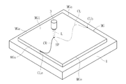
- FIG. 1 to 3 show a first embodiment of a method for manufacturing a glass sheet according to the present invention.
- the method includes a cutting step of cutting the mother glass plate MG to form one or more glass plates.
- the mother glass plate MG is formed in a rectangular shape by cutting a glass ribbon continuously formed in a belt shape in a width direction by a down draw method such as an overflow down draw method or a float method.
- the thickness of mother glass plate MG can be 0.05 to 5 mm.
- the thickness of the mother glass plate MG is preferably greater than 0.1 mm, more preferably greater than 0.2 mm, and 0.3 mm or more. Is even more preferred.
- the material of the mother glass plate MG examples include silicate glass, silica glass, borosilicate glass, soda glass, soda lime glass, aluminosilicate glass, and alkali-free glass.
- the non-alkali glass is a glass that does not substantially contain an alkali component (alkali metal oxide), and specifically, a glass having a weight ratio of the alkali component of 3000 ppm or less. is there.
- the weight ratio of the alkali component in the present invention is preferably 1000 ppm or less, more preferably 500 ppm or less, and most preferably 300 ppm or less.
- the mother glass plate MG may be chemically strengthened glass, and in this case, aluminosilicate glass can be used.
- the cleaving step includes a step of forming an initial crack in the mother glass plate MG (initial crack formation step) and a laser irradiation step of developing the initial crack.
- an initial crack is formed by the crack forming member 2 on a part of the first surface MG1 (hereinafter, also simply referred to as “front surface”) of the mother glass plate MG placed on the surface plate 1.
- a curved cutting line CL is set on the mother glass plate MG.
- the scheduled cutting line CL has a cutting start point CLa set at one end and a cutting end point CLb set at the other end.
- the cutting start point CLa and the cutting end point CLb are set at the edge MGa of the mother glass plate MG (midway of one side MGa of the rectangular mother glass plate MG).
- the crack forming member 2 is configured by a pointed scriber such as a sintered diamond cutter, but is not limited thereto, and may be configured by a diamond pen, a cemented carbide cutter, sandpaper, or the like.
- the crack forming member 2 descends from above the mother glass plate MG and contacts the edge MGa of the mother glass plate MG. Thereby, an initial crack is formed at the cutting start point CLa of the planned cutting line CL.
- the laser beam L is applied to the initial cracks on the first surface MG1 by the laser irradiation device 3, and the laser beam L is scanned along the scheduled cutting line CL.
- the laser irradiation device 3 is configured to be three-dimensionally movable, and moves the laser beam L in a predetermined direction above the mother glass plate MG placed on the surface plate 1 so as to emit the laser light L. Scanning is performed from the cutting start point CLa to the cutting end point CLb along the planned cutting line CL.
- the crack CR starting from the initial crack propagates along the planned cutting line CL.
- the crack CR extends over the entire thickness of the mother glass plate MG, and extends to the second surface MG2 located on the opposite side of the first surface MG1.
- the laser beam L emitted from the laser irradiation device 3 is preferably a CO laser, an Er laser (Er: YAG laser), a Ho laser (Ho: YAG laser), or an HF laser.
- the laser beam L may be a pulse laser beam or a continuous laser beam.
- the wavelength is preferably set to be 5.25 to 5.75 ⁇ m.
- the laser irradiation device 3 irradiates the laser light L such that a circular laser spot SP is formed on the surface MG1 of the mother glass plate MG.
- the irradiation diameter (spot diameter) of the laser beam L is preferably 1 to 8 mm, more preferably 2 to 6 mm.
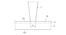
- the surface layer SL (for example, a range from the surface MG1 to a depth of about 10 ⁇ m) of the mother glass plate MG (first surface MG1) is only heated.
- a coolant such as cooling water
- the mother glass plate MG can be used. Not only the surface layer SL but also an internal IL (for example, a depth of about 10 ⁇ m to a depth of about 3,000 ⁇ m) can be heated, and a sufficient amount of heat is generated to generate a thermal shock (thermal stress) that propagates the crack CR in the thickness direction. Can be given.
- an internal IL for example, a depth of about 10 ⁇ m to a depth of about 3,000 ⁇ m
- the surface layer SL of the mother glass plate MG refers to a layer extending from the surface MG1 of the mother glass plate MG to a depth of 10 ⁇ m.
- the internal IL of the mother glass plate MG refers to a region having a depth exceeding 10 ⁇ m from the surface MG1 (see FIG. 3).
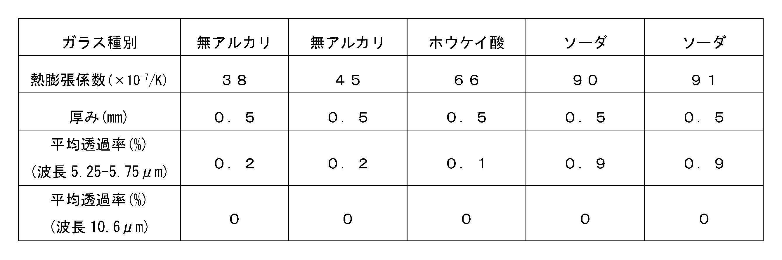
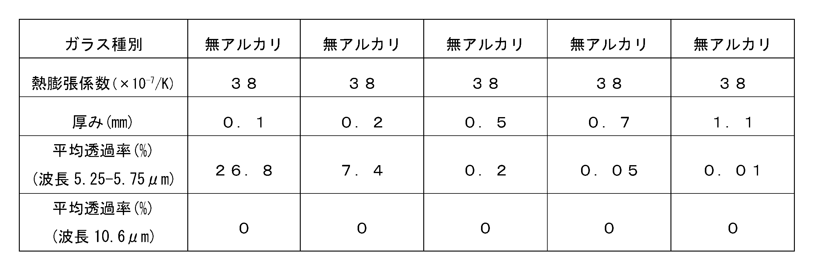
- Tables 1 and 2 below show the average transmittance of each mother glass plate MG when a plurality of types of mother glass plates MG having a predetermined thickness are irradiated with a CO laser and a CO 2 laser.
- the wavelength of the CO laser has a peak around 5.25-5.75 ⁇ m, and the average transmittance of various mother glass plates MG at this wavelength is not zero. That is, the irradiated CO laser is not entirely absorbed on the surface of the mother glass plate MG, but is partially absorbed inside the glass plate and the remaining portion is transmitted through the mother glass plate MG. Therefore, according to the CO laser, not only the surface of the mother glass plate MG but also the inside of the mother glass plate MG can be heated.
- the wavelength of the CO 2 laser has a peak near 10.6 ⁇ m, and the average transmittance of various mother glass plates MG in this vicinity is zero.
- most of the irradiated CO 2 laser is absorbed on the surface of the mother glass plate MG, and is not absorbed inside the mother glass plate MG. Therefore, the inside of the mother glass plate MG cannot be heated by the CO 2 laser.
- the bending stress is applied to the mother glass plate MG by heating not only the surface layer SL of the mother glass plate MG but also the internal IL to propagate the crack CR in the thickness direction.
- the mother glass plate MG can be separated along the planned cutting line CL, the step of breaking can be omitted. Further, it becomes possible to cut the mother glass plate MG without cooling it with a refrigerant as in the related art.
- the mother glass plate MG can be suitably cut even if the planned cutting line CL is formed in a curved shape. Thereby, glass plates of various shapes can be cut out from mother glass plate MG.
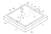
- FIG. 4 shows a second embodiment of the method for manufacturing a glass sheet according to the present invention.
- the present embodiment is different from the first embodiment in that, in the cutting step, the periphery of the irradiation area (laser spot SP) of the laser beam L is cooled by the refrigerant R (for example, air) injected from the cooling device 4.
- the refrigerant R for example, air
- the cooling device 4 is configured to move following the laser irradiation device 3.
- the cooling device 4 injects the coolant R from the nozzle toward the irradiation area (laser spot SP) of the laser beam L and the periphery thereof.
- an inert gas such as He or Ar or a non-oxidized N 2 gas is preferably used.
- a thermal shock for developing the crack CR can be more remarkably generated.
- the output of the CO laser is attenuated by the water because the CO laser light absorbs water. Therefore, it is better not to use water as the refrigerant R. However, this is not the case when the output attenuation is used effectively.
- the laser irradiation device 3 and the cooling device 4 may be integrally formed.
- the injection port of the nozzle of the cooling device 4 may be formed in an annular shape, and the laser irradiation device 3 may be disposed inside the annular injection port.
- the crack CR may slightly deviate from the planned cutting line CL and may progress depending on the cutting conditions.
- the deviation can be reduced by cooling the periphery of the irradiation site (laser spot SP) of the laser beam L.
- the cooling can be performed from behind, in front of, and from the side of the irradiated portion (laser spot SP) of the laser beam L.
- performing cooling from the front means that cooling is performed using the cooling device 4 disposed closer to the cutting end point CLb than the laser spot SP (laser irradiation device 3).
- To perform cooling from the rear means to perform cooling using the cooling device 4 arranged closer to the cutting start point CLa than the laser spot SP (laser irradiation device 3).
- the injection range of the coolant R by the nozzle of the cooling device 4 does not have to overlap with the laser spot SP. That is, the coolant R may be injected at a position away from the laser spot SP. From the viewpoint of further reducing the deviation of the crack CR, the shorter the distance between the injection range of the refrigerant R by the nozzle of the cooling device 4 and the laser spot SP, the more preferable. Are more preferably overlapped.
- the injection range of the refrigerant R by the nozzle means a range in which the refrigerant R injected from the nozzle directly reaches the mother glass plate MG and cools, and the refrigerant in which the flow direction changes in contact with the mother glass plate MG. This excludes the case where R indirectly reaches the laser spot SP and cools.
- the scanning speed of the laser beam L is low.
- the scanning speed of the laser beam L is preferably 3 to 15 mm / sec, and the thickness is less than 0.4 mm. If so, the scanning speed is preferably set to 3 to 100 mm / sec.
- the preferable scanning speed of the laser beam L changes depending on the material of the mother glass plate MG, and tends to increase as the coefficient of thermal expansion increases. Further, the preferable scanning speed of the laser beam L tends to increase as the thickness of the mother glass plate MG decreases.
- the flow rate of the refrigerant R injected from the nozzle can be, for example, 10 to 50 l / min.
- FIG. 5 shows a third embodiment of the method for producing a glass sheet according to the present invention.
- the configuration of the cooling device 4 is different from that of the second embodiment.
- the cooling device 4 according to the present embodiment is provided on the surface plate 1.
- the cooling device 4 has a refrigerant pipe 5 arranged inside or under the surface plate 1.
- the refrigerant pipes 5 are arranged in a meandering manner so as to cool the surface plate 1 in a wide range.
- the surface plate 1 in the laser irradiation step, the surface plate 1 is cooled by flowing a refrigerant made of gas or liquid through the refrigerant pipe 5.
- the second surface (back surface) of mother glass plate MG in contact with surface plate 1 is cooled.
- the second surface of the mother glass plate MG that is in contact with the platen 1 can be cooled almost entirely, so that the growth of the crack CR in the thickness direction can be promoted.
- FIG. 6 shows a fourth embodiment of the method for manufacturing a glass sheet according to the present invention.
- the configuration of the cooling device 4 is different from that of the third embodiment.
- the cooling device 4 according to the present embodiment is configured to cool a part of the surface plate 1.
- the cooling device 4 is provided on a part of the surface plate 1 near the cutting end point CLb so as to cool the cutting end point CLb of the planned cutting line CL set on the mother glass plate MG and the surrounding area CA. I have.
- the area for heating the glass in the cutting area decreases, and the heating by the laser beam L becomes insufficient. For this reason, it is difficult to apply a thermal shock just enough to progress the crack CR, so that uncut portions are easily generated.
- the progress of the crack CR can be promoted at the cutting end point CLb, and the occurrence of uncut portions can be prevented.
- FIGS. 7 and 8 show a fifth embodiment of the method for manufacturing a glass sheet according to the present invention.
- the initial crack in the initial crack formation step, is formed not in the edge portion MGa of the mother glass plate MG but in an area inside the surface MG1 of the mother glass plate MG.
- the inner region refers to a region surrounded by an edge MGa of the mother glass plate MG (four sides of the mother glass plate MG formed in a rectangular shape), and the edge MGa of the mother glass plate MG is an inner region. Is not included.
- a circular scheduled cutting line CL is set in the inner area of the mother glass plate MG.
- the crack forming member 2 is brought into contact with an arbitrary point on the planned cutting line CL as a cutting start point CLa to form an initial crack.
- the CO laser light L is applied to the cleavage start point CLa where the initial crack has been formed, and the CO laser light L is scanned along the planned cleavage line CL to complete the cleavage.
- the point CLb By reaching the point CLb, a circular glass plate can be cut out from the rectangular mother glass plate MG.
- the present invention is not limited to the configuration of the above-described embodiment, nor is it limited to the above-described operation and effect.
- the present invention can be variously modified without departing from the gist of the present invention.
- the laser light was applied to the mother glass plate as a circular laser spot, but the present invention is not limited to this configuration.
- the laser spot may be, for example, elliptical, oval, rectangular, or linear. From the viewpoint of increasing the scantability of laser light and producing glass plates of various shapes such as curves, it is preferable to use a circular laser spot.
- a laser beam angle adjusting mechanism By attaching a laser beam angle adjusting mechanism so that the major axis is always tangential to the planned cutting line, the laser beam can be cut into a free shape.
- the manufacturing method according to the present invention can also be used when a belt-shaped glass ribbon is continuously formed by an overflow down draw method and the glass ribbon is cut as a mother glass plate.
- the mother glass plate MG has a flat plate shape (the surface MG1 is a flat surface).
- the present invention is not limited to this configuration, and the mother glass plate MG has a curved shape (at least the surface MG1 is curved). Surface) can be suitably cut (cut).
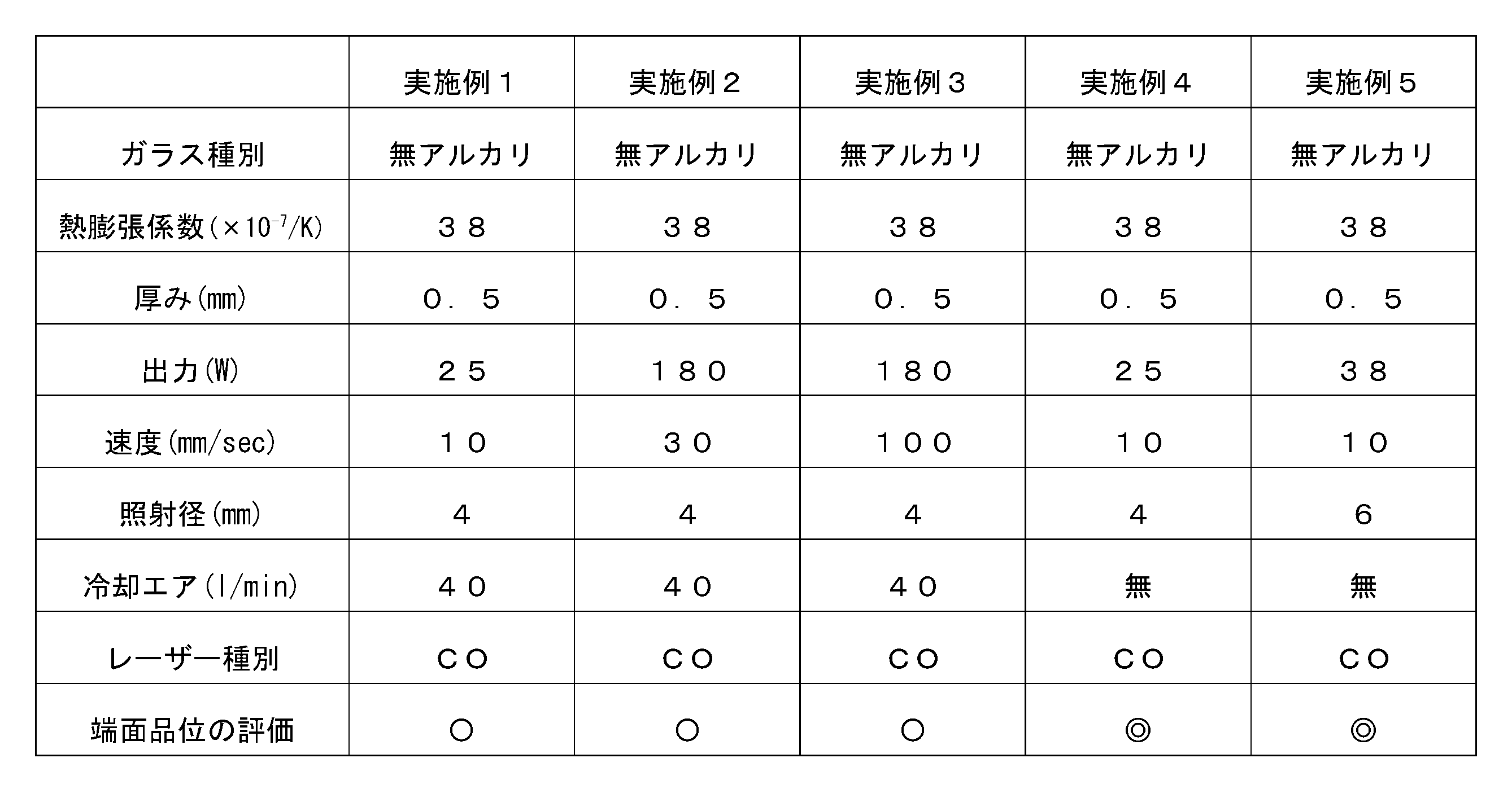
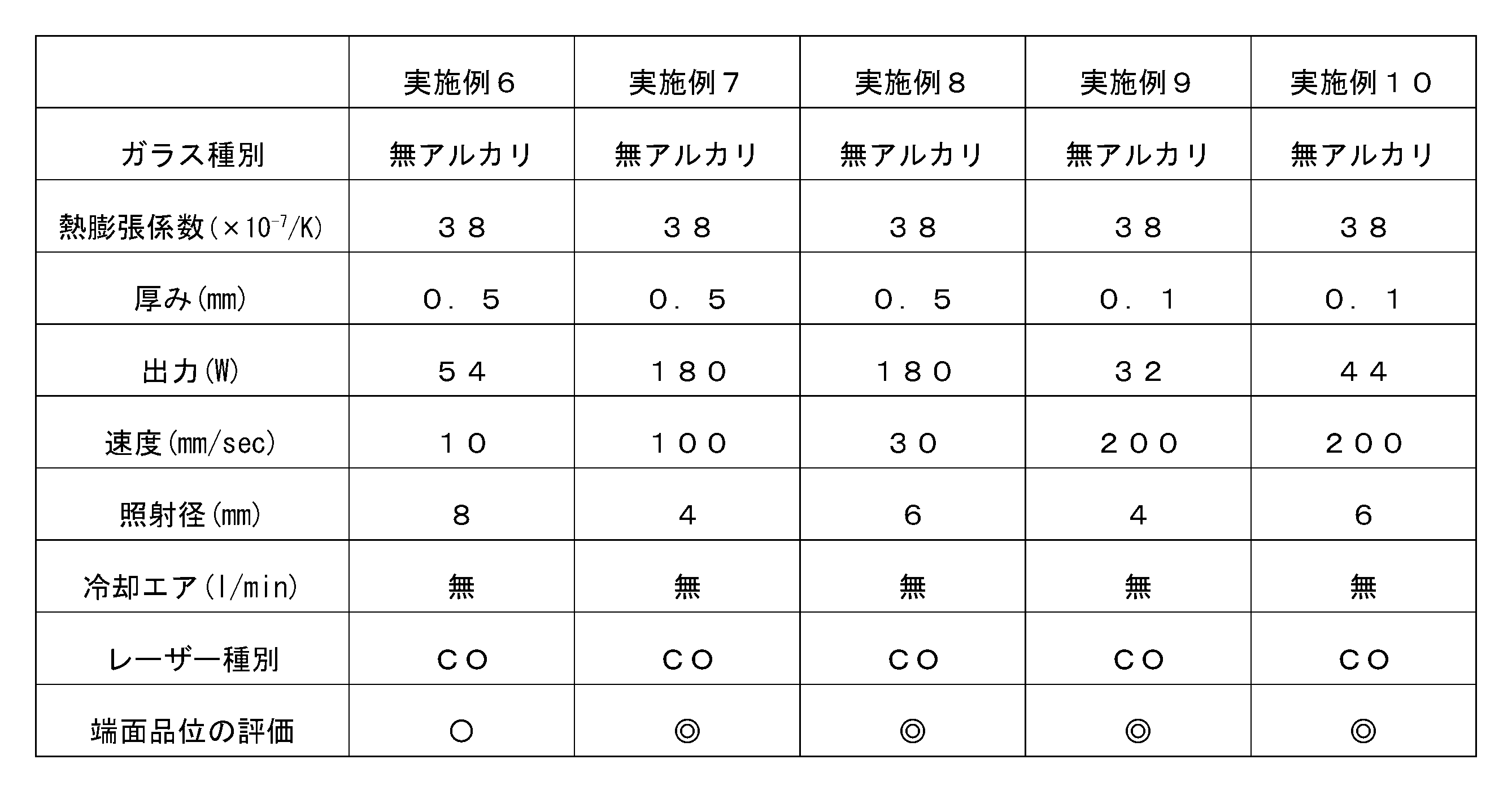
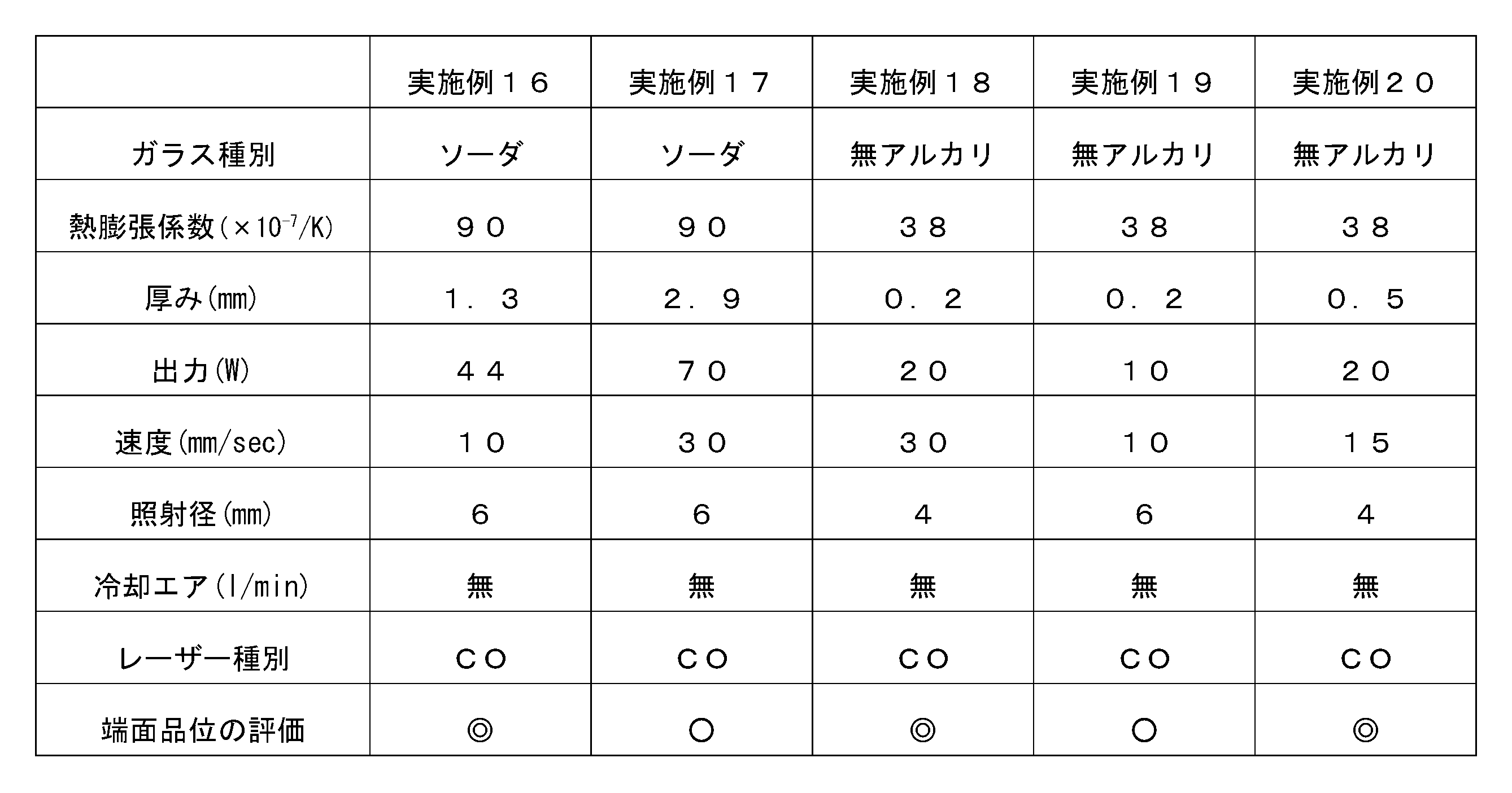
- the present inventors performed a cutting test of a glass plate using a laser irradiation device.
- a mother glass plate having a different thickness is continuously irradiated with a CO laser beam under different conditions (output, scanning speed, irradiation diameter), and the mother glass plate is cut along a cutting line configured in a curved shape.
- the glass plates according to Examples 1 to 11 and 18 to 20 are made of non-alkali glass (product name OA-10G of NEC Corporation).
- the glass plates according to Examples 12 to 16 and 21 to 25 are made of soda glass.
- the glass plates according to Examples 25 to 30 are made of borosilicate glass.
- the cutting was performed by blowing the cooling air to the irradiation position of the laser beam.
- Example 1 to 30 The test conditions and test results of Examples 1 to 30 are shown in Tables 3 to 8 below.
- the quality of the cut surface of the glass plate (the end surface generated by the splitting) was evaluated by visually observing the quality.
- an example having end-face quality as a product was rated “ ⁇ ” (good), and a particularly high-quality example was rated “ ⁇ ” (best).
- a thermal stress ⁇ T (MPa) when a mother glass plate having a thickness of 0.5 mm was cut was calculated by the following mathematical formula 1.
- Table 9 shows the calculation results.
- E is the Young's modulus (MPa) of the mother glass plate
- ⁇ is the coefficient of thermal expansion (/ K) of the mother glass plate
- ⁇ is the Poisson's ratio of the mother glass plate
- ⁇ T is the laser beam irradiation position on the mother glass plate. It is the difference between the temperature (K) and the temperature (K) at a position distant from the irradiation position.
- the thermal stress ⁇ T for obtaining an appropriate cut surface differs for each thickness of the mother glass plate.
- the present inventors conducted a test in which a plurality of mother glass plates having different thicknesses were cut by a CO laser, and confirmed the relationship between the thickness of the mother glass plate and thermal stress. This cutting test was performed on alkali-free glass, soda glass, and borosilicate glass as mother glass plate samples.
- FIG. 9 shows the relationship between the thickness of the mother glass plate and the thermal stress in the cutting test. Under the test conditions shown in FIG. 9, good cut surfaces could be obtained in all cases.
- the present inventors have found that when cutting a mother glass plate with a CO laser, in order to obtain a good cut surface, the thermal stress ⁇ T ( It has been found that it is desirable to perform the laser irradiation step so that MPa) satisfies Equation 2 below.
- t is the thickness (mm) of the mother glass plate.
- the upper surface temperature of the mother glass plate is measured by a glass temperature measurement thermography (manufactured by Optris) at an irradiation position of the laser beam and a separation position separated by 10 mm forward from the irradiation position. PI450G7).
- the difference between the temperature at the irradiation position of the laser beam and the temperature at a distance away from the irradiation position was defined as the temperature difference ⁇ T.
- the temperature of the mother glass plate during laser light irradiation was changed by changing the output and processing speed conditions.
- the temperature at the separation position was about the same as room temperature.
- the present inventors have found through a cutting test that, depending on conditions such as the cutting position of the mother glass plate, the crack slightly deviates from the planned cutting line when the crack propagates along the linear planned cutting line. Was. Therefore, the present inventors conducted a test for measuring the degree of deviation of cracks when the mother glass plate was cut linearly.
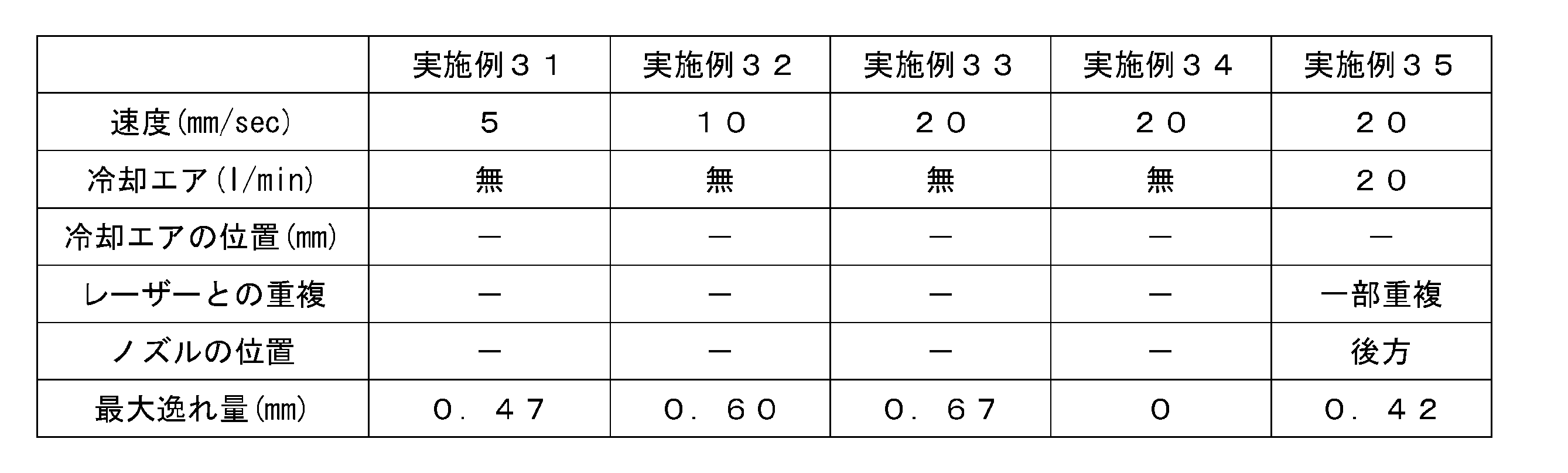
- Examples 31 to 45 a plurality of mother glass plates (Examples 31 to 45) having a square shape (150 mm ⁇ 150 mm) and a thickness of 0.5 mm were prepared.
- the mother glass plates according to Examples 31 to 45 are made of non-alkali glass (OA-10G).
- the thermal expansion coefficients of the mother glass plates according to Examples 31 to 45 are 38 ⁇ 10 ⁇ 7 / K.
- the mother glass plates according to Examples 31 to 45 were cut under different conditions such as the scanning speed of the CO laser beam (irradiation diameter: 6 mm, output: 38 W), cutting position, presence / absence of cooling air, and the like. Further, for each of Examples 31 to 45, the amount (mm) of the deviation of the crack from the planned cutting line was measured.
- FIG. 10 shows cutting positions of the mother glass plate in Examples 31 to 33.
- the mother glass plate MG according to Examples 31 to 33 has four sides (first to fourth sides) MGa1 to MGa4.
- the planned cutting line CL is a straight line set substantially parallel to the first side MGa1.
- the cutting start point CLa of the planned cutting line CL is set to a second side MGa2 perpendicular to the first side MGa1.
- the cutting end point CLb of the planned cutting line CL is set to a third side MGa3 substantially parallel to the second side MGa2.
- the planned cutting line CL is set at a position separated by a predetermined distance D from the first side MGa1 of the mother glass plate MG.
- the distance D between the first side MGa1 and the planned cutting line CL is equal to 1 / of the length L1 of the second side MGa2.
- the mother glass plate MG was cut in the same manner as in the first embodiment without changing the scanning speed of the CO laser beam and using cooling air.
- the crack CR slightly deviated from the planned cutting line CL and developed in a curved shape (arc shape).
- the amount of deviation (the distance from the predetermined line CL to the crack CR) is the largest at the intermediate position MP (half the length of the predetermined line CL) of the predetermined line CL. It turned out to be.
- the maximum deviation amount of the crack CR corresponding to the intermediate position MP of the planned cutting line CL according to Examples 31 to 33 is indicated by a symbol DVmax.
- FIG. 11 shows a cutting position of the mother glass plate according to Example 34.
- the position of the planned cutting line CL (distance D from the first side MGa1) is different from those of the above-described 31st to 33rd embodiments.
- the distance D between the first side MGa1 and the planned cutting line CL in the thirty-fourth embodiment is equal to half the length L1 of the second side MGa2.
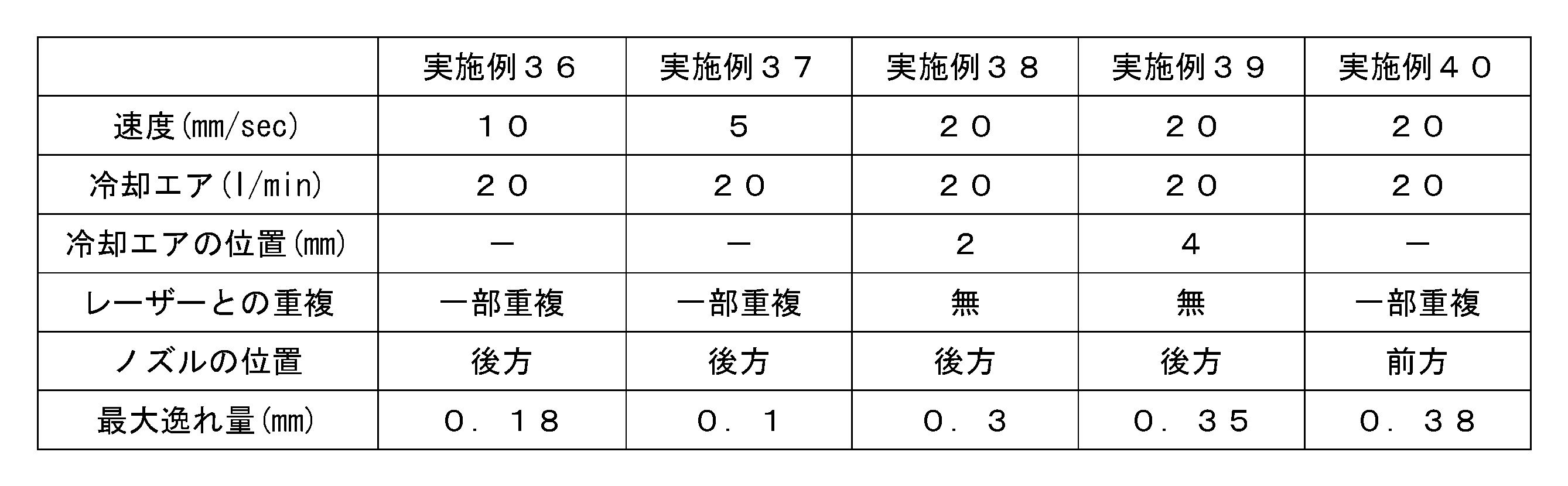
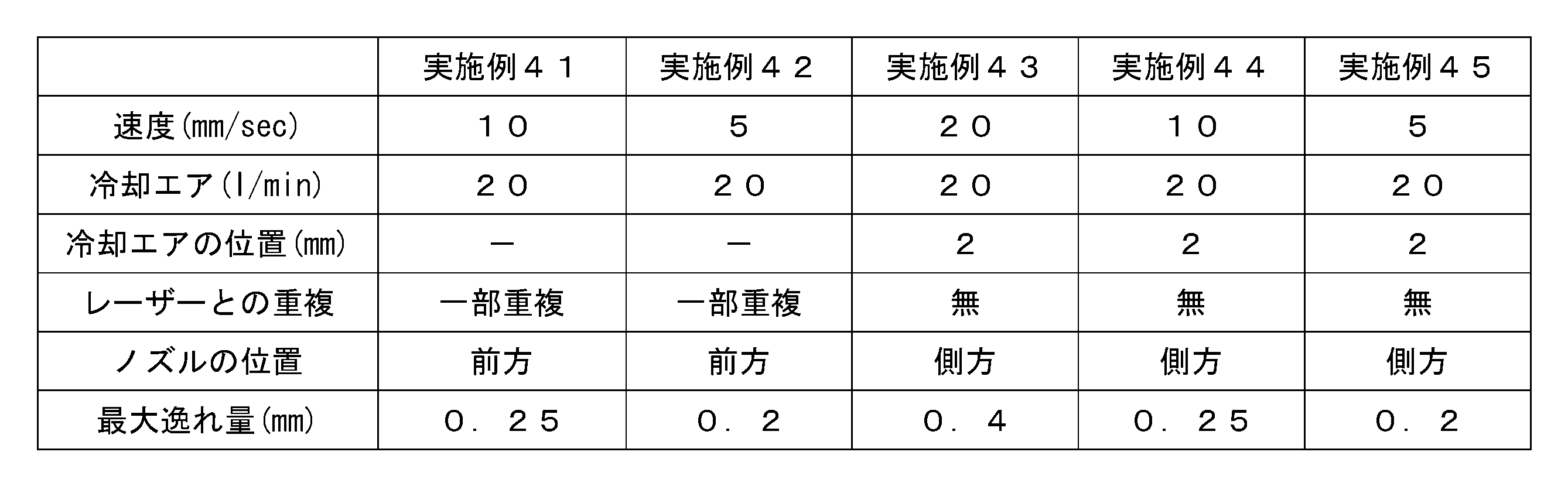
- Examples 35 to 45 the mother glass plate was cut at the same cutting position as in Examples 31 to 33 (see FIG. 10).
- the scanning speed of the CO laser beam was changed, and the mother glass plate was cut using cooling air.
- the conditions were divided into a case where the injection range of the cooling air partially overlaps the laser spot of the CO laser beam and a case where the cooling air is injected toward a position away from the laser spot.
- the position of the nozzle of the cooling device with respect to the laser irradiation device was divided into the front, the rear, and the side, and the mother glass plate was cut.
- Tables 10 to 12 show the measured values of the scanning speed of the laser beam, the conditions of the cooling air, and the maximum amount of deviation of the crack (DVmax) according to Examples 31 to 45.
- the “position of the cooling air” in Tables 10 to 12 indicates the separation distance (mm) between the laser air spot and the range of the cooling air that is in contact with the mother glass plate when the cooling air is injected toward a position away from the laser spot. ).
Landscapes
- Chemical & Material Sciences (AREA)
- Materials Engineering (AREA)
- Engineering & Computer Science (AREA)
- Organic Chemistry (AREA)
- Physics & Mathematics (AREA)
- Optics & Photonics (AREA)
- Health & Medical Sciences (AREA)
- Toxicology (AREA)
- Thermal Sciences (AREA)
- Life Sciences & Earth Sciences (AREA)
- Geochemistry & Mineralogy (AREA)
- General Chemical & Material Sciences (AREA)
- Chemical Kinetics & Catalysis (AREA)
- Re-Forming, After-Treatment, Cutting And Transporting Of Glass Products (AREA)
- Glass Compositions (AREA)
- Processing Of Stones Or Stones Resemblance Materials (AREA)
Abstract
Description








CL 割断予定線
CR クラック
IL マザーガラス板の内部
L レーザー光
MG マザーガラス板
MG1 第一表面
MG2 第二表面
SL マザーガラス板(第一表面)の表層
SP レーザースポット
Claims (9)
- マザーガラス板の第一表面に初期クラックを形成する初期クラック形成工程と、前記第一表面にレーザー光を照射することにより、前記初期クラックを起点としてクラックを割断予定線に沿って進展させるレーザー照射工程とを備えるガラス板の製造方法において、
前記レーザー照射工程は、前記レーザー光を前記マザーガラス板に照射することで、前記第一表面の表層及び内部を加熱し、前記加熱に伴う熱衝撃によって前記クラックを前記割断予定線に沿って進展させながら、前記マザーガラス板の厚み方向に沿って前記マザーガラス板の第二表面まで進展させることを特徴とするガラス板の製造方法。 - 前記レーザー光は、COレーザー光である請求項1に記載のガラス板の製造方法。
- マザーガラス板の第一表面に初期クラックを形成する初期クラック形成工程と、前記第一表面にレーザー光を照射することにより、前記初期クラックを起点としてクラックを割断予定線に沿って進展させるレーザー照射工程とを備えるガラス板の製造方法において、
前記レーザー照射工程は、前記レーザー光としてCOレーザー光、Erレーザー光、Hoレーザー光又はHFレーザー光を照射することで、前記クラックを前記割断予定線に沿って進展させながら、前記マザーガラス板の厚み方向に沿って前記マザーガラス板の第二表面まで進展させることを特徴とするガラス板の製造方法。 - 前記レーザー光を円形のレーザースポットとして照射する請求項1から3のいずれか一項に記載のガラス板の製造方法。
- 前記レーザー照射工程では、前記レーザー光の照射位置の周囲を冷却する請求項4に記載のガラス板の製造方法。
- 前記レーザー照射工程では、前記マザーガラス板を定盤で支持するとともに、前記定盤を冷却する請求項1から5のいずれか一項に記載のガラス板の製造方法。
- 前記レーザー照射工程では、前記割断予定線の割断終了点付近の前記定盤の一部を冷却する請求項6に記載のガラス板の製造方法。
- 前記初期クラック形成工程では、前記初期クラックを前記マザーガラス板の内側領域に形成する請求項1から7のいずれか一項に記載のガラス板の製造方法。
- 前記レーザー照射工程を、以下の数式1で算出される前記マザーガラス板の熱応力σT(MPa)が以下の数式2を満足する条件で実施する請求項1から8のいずれか一項に記載のガラス板の製造方法。


Priority Applications (4)
| Application Number | Priority Date | Filing Date | Title |
|---|---|---|---|
| CN201980044229.6A CN112384481A (zh) | 2018-08-10 | 2019-08-07 | 玻璃板的制造方法 |
| KR1020207032513A KR102676068B1 (ko) | 2018-08-10 | 2019-08-07 | 유리판의 제조 방법 |
| US17/262,845 US20210188691A1 (en) | 2018-08-10 | 2019-08-07 | Method for manufacturing glass sheet |
| JP2020535843A JP7318651B2 (ja) | 2018-08-10 | 2019-08-07 | ガラス板の製造方法 |
Applications Claiming Priority (2)
| Application Number | Priority Date | Filing Date | Title |
|---|---|---|---|
| JP2018-151393 | 2018-08-10 | ||
| JP2018151393 | 2018-08-10 |
Publications (1)
| Publication Number | Publication Date |
|---|---|
| WO2020032124A1 true WO2020032124A1 (ja) | 2020-02-13 |
Family
ID=69413488
Family Applications (1)
| Application Number | Title | Priority Date | Filing Date |
|---|---|---|---|
| PCT/JP2019/031182 Ceased WO2020032124A1 (ja) | 2018-08-10 | 2019-08-07 | ガラス板の製造方法 |
Country Status (6)
| Country | Link |
|---|---|
| US (1) | US20210188691A1 (ja) |
| JP (1) | JP7318651B2 (ja) |
| KR (1) | KR102676068B1 (ja) |
| CN (1) | CN112384481A (ja) |
| TW (1) | TWI812769B (ja) |
| WO (1) | WO2020032124A1 (ja) |
Cited By (1)
| Publication number | Priority date | Publication date | Assignee | Title |
|---|---|---|---|---|
| WO2023228617A1 (ja) * | 2022-05-27 | 2023-11-30 | 日本電気硝子株式会社 | ガラス板の製造方法 |
Families Citing this family (2)
| Publication number | Priority date | Publication date | Assignee | Title |
|---|---|---|---|---|
| US10951254B1 (en) * | 2020-02-27 | 2021-03-16 | Eli Altaras | Foldable phone case method and devices |
| CN111922532A (zh) * | 2020-08-13 | 2020-11-13 | 晶科能源有限公司 | 太阳能电池片加工设备及加工方法 |
Citations (7)
| Publication number | Priority date | Publication date | Assignee | Title |
|---|---|---|---|---|
| WO2003076151A1 (en) * | 2002-03-12 | 2003-09-18 | Mitsuboshi Diamond Industrial Co., Ltd. | Method and device for processing fragile material |
| JP2015120604A (ja) * | 2012-04-06 | 2015-07-02 | 旭硝子株式会社 | 強化ガラス板の切断方法、及び強化ガラス板切断システム |
| JP2016509540A (ja) * | 2013-01-15 | 2016-03-31 | コーニング レーザー テクノロジーズ ゲーエムベーハーCORNING LASER TECHNOLOGIES GmbH | レーザビーム焦線を用いたシート状基板のレーザベースの機械加工方法及び装置 |
| JP2016069223A (ja) * | 2014-09-30 | 2016-05-09 | 三星ダイヤモンド工業株式会社 | ブレイク方法並びにブレイク装置 |
| JP2016128365A (ja) * | 2013-04-26 | 2016-07-14 | 旭硝子株式会社 | ガラス板の切断方法 |
| JP2016536251A (ja) * | 2013-11-04 | 2016-11-24 | コーニング精密素材株式会社Corning Precision Materials Co., Ltd. | 強化ガラス切断方法および強化ガラス切断装置 |
| JP2017128493A (ja) * | 2015-09-04 | 2017-07-27 | 旭硝子株式会社 | ガラス板の製造方法、ガラス物品の製造方法、ガラス板、ガラス物品、およびガラス物品の製造装置 |
Family Cites Families (9)
| Publication number | Priority date | Publication date | Assignee | Title |
|---|---|---|---|---|
| JP2008062547A (ja) * | 2006-09-08 | 2008-03-21 | Hiroshima Univ | レーザ照射による脆性材板割断の方法および装置。 |
| EP2377823A4 (en) * | 2008-12-25 | 2012-06-13 | Asahi Glass Co Ltd | METHOD AND DEVICE FOR CUTTING SPROUTS MATERIAL PLATES AND GLASS FOR A VEHICLE |
| TWI517922B (zh) | 2009-05-13 | 2016-01-21 | 康寧公司 | 切割脆性材料之方法 |
| JP5522516B2 (ja) | 2009-12-07 | 2014-06-18 | 日本電気硝子株式会社 | 板状ガラスの切断方法及びその切断装置 |
| JP5887928B2 (ja) * | 2011-12-28 | 2016-03-16 | 三星ダイヤモンド工業株式会社 | 被加工物の分断方法および光学素子パターン付き基板の分断方法 |
| JP6009225B2 (ja) * | 2012-05-29 | 2016-10-19 | 浜松ホトニクス株式会社 | 強化ガラス板の切断方法 |
| CN106458693B (zh) * | 2014-02-20 | 2020-06-16 | 康宁股份有限公司 | 用于在柔性薄玻璃中切割多个半径的方法和设备 |
| DE102015104801A1 (de) * | 2015-03-27 | 2016-09-29 | Schott Ag | Verfahren und Vorrichtung zum kontinuierlichen Trennen von Glas |
| CN107922239A (zh) * | 2015-08-28 | 2018-04-17 | 康宁股份有限公司 | 包含刻划装置的刻划设备和刻划玻璃带的方法 |
-
2019
- 2019-08-07 KR KR1020207032513A patent/KR102676068B1/ko active Active
- 2019-08-07 CN CN201980044229.6A patent/CN112384481A/zh active Pending
- 2019-08-07 US US17/262,845 patent/US20210188691A1/en not_active Abandoned
- 2019-08-07 WO PCT/JP2019/031182 patent/WO2020032124A1/ja not_active Ceased
- 2019-08-07 JP JP2020535843A patent/JP7318651B2/ja active Active
- 2019-08-08 TW TW108128392A patent/TWI812769B/zh active
Patent Citations (7)
| Publication number | Priority date | Publication date | Assignee | Title |
|---|---|---|---|---|
| WO2003076151A1 (en) * | 2002-03-12 | 2003-09-18 | Mitsuboshi Diamond Industrial Co., Ltd. | Method and device for processing fragile material |
| JP2015120604A (ja) * | 2012-04-06 | 2015-07-02 | 旭硝子株式会社 | 強化ガラス板の切断方法、及び強化ガラス板切断システム |
| JP2016509540A (ja) * | 2013-01-15 | 2016-03-31 | コーニング レーザー テクノロジーズ ゲーエムベーハーCORNING LASER TECHNOLOGIES GmbH | レーザビーム焦線を用いたシート状基板のレーザベースの機械加工方法及び装置 |
| JP2016128365A (ja) * | 2013-04-26 | 2016-07-14 | 旭硝子株式会社 | ガラス板の切断方法 |
| JP2016536251A (ja) * | 2013-11-04 | 2016-11-24 | コーニング精密素材株式会社Corning Precision Materials Co., Ltd. | 強化ガラス切断方法および強化ガラス切断装置 |
| JP2016069223A (ja) * | 2014-09-30 | 2016-05-09 | 三星ダイヤモンド工業株式会社 | ブレイク方法並びにブレイク装置 |
| JP2017128493A (ja) * | 2015-09-04 | 2017-07-27 | 旭硝子株式会社 | ガラス板の製造方法、ガラス物品の製造方法、ガラス板、ガラス物品、およびガラス物品の製造装置 |
Cited By (1)
| Publication number | Priority date | Publication date | Assignee | Title |
|---|---|---|---|---|
| WO2023228617A1 (ja) * | 2022-05-27 | 2023-11-30 | 日本電気硝子株式会社 | ガラス板の製造方法 |
Also Published As
| Publication number | Publication date |
|---|---|
| JP7318651B2 (ja) | 2023-08-01 |
| JPWO2020032124A1 (ja) | 2021-08-26 |
| TWI812769B (zh) | 2023-08-21 |
| TW202012326A (zh) | 2020-04-01 |
| US20210188691A1 (en) | 2021-06-24 |
| KR20210042045A (ko) | 2021-04-16 |
| KR102676068B1 (ko) | 2024-06-18 |
| CN112384481A (zh) | 2021-02-19 |
Similar Documents
| Publication | Publication Date | Title |
|---|---|---|
| US8720228B2 (en) | Methods of separating strengthened glass substrates | |
| CN103857636B (zh) | 用于切割带有特殊的棱边构造的薄玻璃的方法 | |
| CN102574722B (zh) | 薄玻璃的激光划线和折断的方法 | |
| US20110127242A1 (en) | Methods for laser scribing and separating glass substrates | |
| CN103781734A (zh) | 强化玻璃板的切断方法及强化玻璃板切断装置 | |
| CN103596893A (zh) | 玻璃板的切割方法 | |
| WO2010108061A2 (en) | Precision laser scoring | |
| JP7318651B2 (ja) | ガラス板の製造方法 | |
| JP7459536B2 (ja) | ガラス板及びガラス板の製造方法 | |
| JP7515777B2 (ja) | ガラス板の製造方法 | |
| JP7528454B2 (ja) | ガラス板の製造方法 | |
| US12358828B2 (en) | Glass plate manufacturing method |
Legal Events
| Date | Code | Title | Description |
|---|---|---|---|
| 121 | Ep: the epo has been informed by wipo that ep was designated in this application |
Ref document number: 19848444 Country of ref document: EP Kind code of ref document: A1 |
|
| ENP | Entry into the national phase |
Ref document number: 2020535843 Country of ref document: JP Kind code of ref document: A |
|
| ENP | Entry into the national phase |
Ref document number: 20207032513 Country of ref document: KR Kind code of ref document: A |
|
| NENP | Non-entry into the national phase |
Ref country code: DE |
|
| 122 | Ep: pct application non-entry in european phase |
Ref document number: 19848444 Country of ref document: EP Kind code of ref document: A1 |