WO2020031649A1 - ホットメルトブロック、ケーブルの製造方法及びケーブル - Google Patents
ホットメルトブロック、ケーブルの製造方法及びケーブル Download PDFInfo
- Publication number
- WO2020031649A1 WO2020031649A1 PCT/JP2019/028263 JP2019028263W WO2020031649A1 WO 2020031649 A1 WO2020031649 A1 WO 2020031649A1 JP 2019028263 W JP2019028263 W JP 2019028263W WO 2020031649 A1 WO2020031649 A1 WO 2020031649A1
- Authority
- WO
- WIPO (PCT)
- Prior art keywords
- electric wires
- sheath
- hot melt
- cable
- wires
- Prior art date
- Legal status (The legal status is an assumption and is not a legal conclusion. Google has not performed a legal analysis and makes no representation as to the accuracy of the status listed.)
- Ceased
Links
Images


Classifications
-
- H—ELECTRICITY
- H02—GENERATION; CONVERSION OR DISTRIBUTION OF ELECTRIC POWER
- H02G—INSTALLATION OF ELECTRIC CABLES OR LINES, OR OF COMBINED OPTICAL AND ELECTRIC CABLES OR LINES
- H02G1/00—Methods or apparatus specially adapted for installing, maintaining, repairing or dismantling electric cables or lines
- H02G1/14—Methods or apparatus specially adapted for installing, maintaining, repairing or dismantling electric cables or lines for joining or terminating cables
-
- B—PERFORMING OPERATIONS; TRANSPORTING
- B60—VEHICLES IN GENERAL
- B60R—VEHICLES, VEHICLE FITTINGS, OR VEHICLE PARTS, NOT OTHERWISE PROVIDED FOR
- B60R16/00—Electric or fluid circuits specially adapted for vehicles and not otherwise provided for; Arrangement of elements of electric or fluid circuits specially adapted for vehicles and not otherwise provided for
- B60R16/02—Electric or fluid circuits specially adapted for vehicles and not otherwise provided for; Arrangement of elements of electric or fluid circuits specially adapted for vehicles and not otherwise provided for electric constitutive elements
-
- H—ELECTRICITY
- H01—ELECTRIC ELEMENTS
- H01B—CABLES; CONDUCTORS; INSULATORS; SELECTION OF MATERIALS FOR THEIR CONDUCTIVE, INSULATING OR DIELECTRIC PROPERTIES
- H01B13/00—Apparatus or processes specially adapted for manufacturing conductors or cables
-
- H—ELECTRICITY
- H01—ELECTRIC ELEMENTS
- H01B—CABLES; CONDUCTORS; INSULATORS; SELECTION OF MATERIALS FOR THEIR CONDUCTIVE, INSULATING OR DIELECTRIC PROPERTIES
- H01B13/00—Apparatus or processes specially adapted for manufacturing conductors or cables
- H01B13/32—Filling or coating with impervious material
-
- H—ELECTRICITY
- H01—ELECTRIC ELEMENTS
- H01B—CABLES; CONDUCTORS; INSULATORS; SELECTION OF MATERIALS FOR THEIR CONDUCTIVE, INSULATING OR DIELECTRIC PROPERTIES
- H01B7/00—Insulated conductors or cables characterised by their form
-
- H—ELECTRICITY
- H01—ELECTRIC ELEMENTS
- H01B—CABLES; CONDUCTORS; INSULATORS; SELECTION OF MATERIALS FOR THEIR CONDUCTIVE, INSULATING OR DIELECTRIC PROPERTIES
- H01B7/00—Insulated conductors or cables characterised by their form
- H01B7/17—Protection against damage caused by external factors, e.g. sheaths or armouring
- H01B7/28—Protection against damage caused by moisture, corrosion, chemical attack or weather
- H01B7/282—Preventing penetration of fluid, e.g. water or humidity, into conductor or cable
-
- H—ELECTRICITY
- H02—GENERATION; CONVERSION OR DISTRIBUTION OF ELECTRIC POWER
- H02G—INSTALLATION OF ELECTRIC CABLES OR LINES, OR OF COMBINED OPTICAL AND ELECTRIC CABLES OR LINES
- H02G15/00—Cable fittings
- H02G15/02—Cable terminations
- H02G15/04—Cable-end sealings
-
- H—ELECTRICITY
- H02—GENERATION; CONVERSION OR DISTRIBUTION OF ELECTRIC POWER
- H02G—INSTALLATION OF ELECTRIC CABLES OR LINES, OR OF COMBINED OPTICAL AND ELECTRIC CABLES OR LINES
- H02G3/00—Installations of electric cables or lines or protective tubing therefor in or on buildings, equivalent structures or vehicles
- H02G3/02—Details
- H02G3/04—Protective tubing or conduits, e.g. cable ladders or cable troughs
Definitions
- This specification discloses a technique for suppressing intrusion of water into a cable.
- Patent Literature 1 a hot-melt block having a cross-shaped cross section is assembled between respective wires drawn from a multi-core cable in which a plurality of wires are collectively surrounded by a sheath, and the hot-melt block partitions the wires.
- a partition wall is provided.
- the multi-core cable includes a heat-shrinkable tube that covers the outer periphery of the plurality of electric wires to which the hot melt block is assembled and the outer periphery of the sheath.
- Heat treatment is performed on the multi-core cable to melt the hot melt block and fill it between the wires, thereby stopping the water between the wires and heat shrinking the heat-shrinkable tube to heat-shrink the outer circumference of multiple wires and the sheath. It is configured to stop water between the outer circumference.
- the position of the hot melt block assembled between a plurality of electric wires is maintained by disposing a partition wall between the electric wires. If the block is displaced, there is a gap between the plurality of electric wires in which the molten hot melt is not filled, and there is a concern that the water stopping performance of the cable may be reduced.
- the hot melt block described in the present specification is assembled at a place where a plurality of electric wires are collectively surrounded by an insulating sheath, the sheath of the cable is removed, and the plurality of electric wires are drawn out, and heating is performed.
- the method for manufacturing a cable described in the present specification is characterized in that a hot melt block is provided at a place where a plurality of electric wires are collectively surrounded by an insulating sheath, the sheath is removed, and the plurality of electric wires are drawn out. While assembling, the heat-shrink tube and the heat-shrink tube are heated in a state where the plurality of electric wires to which the hot-melt block is assembled are surrounded by the heat-shrinkable tube, and the heat is melted while the hot-melt block is melted.
- a method for manufacturing a cable that shrinks and contracts a shrinkable tube wherein the hot melt block has an insertion portion that can be inserted between the plurality of wires surrounded by the sheath, and the insertion portion is fixed, A spacer portion disposed between the plurality of electric wires in a state where the sheath has been removed and pulled out, The hot melt block is assembled to the cable so that the insertion portion is inserted between the plurality of enclosed wires, and the spacer portion is arranged between the plurality of wires in a state where the sheath is removed and pulled out. Performing an assembling step and a heating step of heating the hot melt block and the heat shrinkable tube in a state where the cable to which the hot melt block has been assembled in the assembling step is inserted into a heat shrinkable tube.
- the cable described in the present specification includes a plurality of electric wires, an insulative sheath that encloses the plurality of electric wires collectively, and the plurality of ends in a state where the sheath is removed and the sheath is removed.
- the insertion portion of the hot melt block by inserting the insertion portion of the hot melt block between the plurality of electric wires surrounded by the sheath, it is possible to suppress the displacement of the hot melt block during heating. As a result, it is possible to suppress a decrease in the water stopping performance due to the displacement of the hot melt block. Further, if the insertion portion is melted by heating, it is possible to fill the gap between the plurality of electric wires surrounded by the sheath, so that it is possible to suppress water from entering between the plurality of electric wires.
- the insertion portion is tapered. With this configuration, the insertion of the insertion portion when the hot melt block is assembled can be easily performed.
- the insertion portion is provided with an insertion wall that partitions between the adjacent electric wires. According to this configuration, the positioning accuracy of the insertion portion can be improved by the insertion wall that partitions between the adjacent electric wires.
- the spacer portion includes a main body disposed between the plurality of electric wires, and a protrusion extending radially from a rear end of the main body to partition the electric wires. In this case, the space between the adjacent electric wires can be maintained by the overhang.
- the plurality of electric wires include a signal line and a power line having an outer diameter larger than that of the signal line. According to this configuration, since the outer diameters of the plurality of electric wires are different from each other, the hot melt block is easily shifted in position between the plurality of electric wires. The displacement can be suppressed.
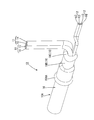
- FIG. 2 is a perspective view illustrating a portion where the cable according to the first embodiment is stopped.
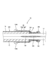
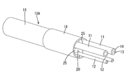
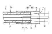
- Sectional view showing where the cable is stopped Exploded perspective view of cable Perspective view showing a state where a hot melt block is assembled to a cable and inserted into a heat shrink tube.
- the cable 10 (FIG. 1) of the present embodiment can be routed between a power supply such as a battery and a load such as a vehicle-mounted electric component or a motor in a vehicle such as an automobile.
- a power supply such as a battery
- a load such as a vehicle-mounted electric component or a motor in a vehicle such as an automobile.
- the cable 10 can be arranged in an arbitrary direction, hereinafter, the left side of FIG. 2 will be described as the front and the right side will be the rear.
- the cable 10 has a cable body 10 ⁇ / b> A in which the sheath 16 is removed and the plurality of electric wires 11 and 12 are pulled out to the rear side, and a portion where the plurality of electric wires 11 and 12 are drawn out. And a heat-shrinkable tube 19 that covers a region between the end portion of the sheath 16 and the plurality of electric wires 11 and 12 drawn rearward in a tight contact state.
- the cable body 10A includes a plurality of electric wires 11 and 12, a sheath 16 surrounding the plurality of electric wires 11 and 12 collectively, and a filling member 17 arranged in a gap between the plurality of electric wires 11 and 12 and the sheath 16.
- the plurality of electric wires 11 and 12 are four electric wires having a circular outer periphery, two power lines 11 through which a drive current such as a motor flows, and two electric lines through which a smaller current flows than the power line 11.
- an outer diameter of the signal line 12 is smaller than an outer diameter of the power line 11.
- Each of the electric wires 11 and 12 includes a core wire 13 and an insulating coating 14 made of an insulating synthetic resin that covers the outer periphery of the core wire 13.
- the core wire 13 is made of, for example, a metal such as aluminum, an aluminum alloy, copper, or a copper alloy, and a stranded wire formed by twisting fine metal wires, a single core wire made of a single metal, or the like can be used.
- a terminal (not shown) connected to a mating terminal (not shown) is attached to the end of each of the wires 11 and 12 by crimping or the like on the core wire 13 in a state where the insulating coating 14 is removed and exposed. I have.
- the sheath 16 is made of insulating synthetic resin, has a cylindrical shape that encloses the plurality of electric wires 11 and 12 collectively, has a terminal 16A from which the rear end side of the sheath 16 has been removed, and has an inside of the sheath 16. A plurality of electric wires 11, 12 are drawn out behind the terminal 16A.
- the filling member 17 is formed by, for example, stuffing an insulating thread or paper tape between the electric wires 11 and 12 and the sheath 16, and filling the gap between the electric wires 11 and 12 and the sheath 16. The positions of the electric wires 11 and 12 are maintained, and deformation such as bending of the electric wires 11 and 12 is suppressed.
- the electric wires 11 and 12 surrounded by the sheath 16 extend rearward from the rear end surface of the filling member 17.
- the hot melt 18 fills the embedded portion 18A embedded between the wires 11 and 12 in the sheath 16 and fills the inside of the heat-shrinkable tube 19 in a region where the plurality of wires 11 and 12 are drawn out. And a filling portion 18B to be filled.
- the hot melt 18 behind the filling portion 18B is a bulging portion 18C protruding from the sheath 16.
- the hot melt 18 is made of a solid thermoplastic adhesive (for example, PA (polyamide), EVA (ethylene vinyl alcohol), polyester-based adhesive, olefin, or the like) at a predetermined temperature (for example, 25 degrees).
- PA polyamide
- EVA ethylene vinyl alcohol
- polyester-based adhesive olefin, or the like
- the block 20 develops adhesiveness by being softened or melted by heating, and then solidified to form the hot melt 18.
- the hot melt block 20 includes an insertion portion 21 that can be inserted from a rear side (outside) between the plurality of electric wires 11 and 12 surrounded by the terminal 16 ⁇ / b> A of the sheath 16. And a cross-shaped spacer portion 24 formed between the electric wires 11 and 12 behind the terminal 16A of the sheath 16.
- the insertion portion 21 has a conical tapered portion 21A whose outer diameter decreases toward the tip, and a columnar column 22 connected to the rear of the tapered portion 21A. After melting in a state where the insertion portion 21 is inserted between the plurality of wires 11 and 12 surrounded by the sheath 16, the material is solidified to form an embedded portion 18 ⁇ / b> A and closely adhere to the plurality of wires 11 and 12 in the sheath 16 ( (See FIG. 2). As shown in FIG.
- the spacer portion 24 includes a core portion 24 ⁇ / b> A connected to the rear of the insertion portion 21, and a partition wall 25 extending in a cross shape from the core portion 24 ⁇ / b> A in four directions to partition between the electric wires 11 and 12.
- Each partition wall 25 has a rectangular plate shape, and the electric wires 11 and 12 are arranged in a space between adjacent partition walls 25 in an aligned state.
- the hot melt block 20 can be integrally formed by molding which injects a molten resin into a mold.
- the molding of the hot melt block 20 is not limited to this, and the insertion part 21 and the spacer part 24 may be separately formed, and the insertion part 21 may be fixed to the front end of the spacer part 24 by bonding or the like.
- the heat-shrinkable tube 19 is a tubular member that shrinks by heating, and has a size that surrounds the end of the sheath 16 and the plurality of electric wires 11 and 12 drawn out from the end of the sheath 16 before heating. After heating, it contracts, and the front end side (one end side) is in close contact with the outer peripheral surface of the sheath 16, and the rear end side (the other end side) is in close contact with the outer peripheral surfaces of the plurality of wires 11 and 12 drawn out. .
- the heat-shrinkable tube 19 can be made of, for example, a two-layer synthetic resin material.
- the outer layer 19B is made of, for example, a polyolefin resin and a modified product thereof.
- the inner layer 19A is made of, for example, EVA (ethylene vinyl alcohol).
- An adhesive made of PA (polyamide), polyester-based adhesive, or the like can be used.
- the adhesive can be a thermoplastic adhesive that exhibits adhesiveness when softened or melted by heating.
- the front side of the inner layer 19 is formed as a protruding portion 19AA protruding forward of the outer layer 19B.
- Assembling of the hot melt block 20 is performed by inserting the insertion portion 21 of the hot melt block 20 between the plurality of electric wires 11 and 12 surrounded by the terminal 16A of the sheath 16 so that the partition wall 25 adjacent to the hot melt block 20 can be inserted.
- the electric wires 11 and 12 are inserted into the space.
- the heating process is performed by inserting the cable 10 into a heating device (not shown).
- a heating device not shown.
- the melted hot melt block 20 penetrates and fills between the wires 11 and 12, and then solidifies, thereby stopping water between the plurality of wires 11 and 12 and thermally contracting the heat-shrinkable tube 19. Thereby, the outer peripheral side of the sheath 16 and the outer peripheral sides of the electric wires 11 and 12 are stopped.
- the position of the hot melt block 20 is maintained by inserting the insertion portion 21 of the hot melt block 20 between the plurality of electric wires 11 and 12 surrounded by the sheath 16. 20 can be suppressed from being displaced during heating. As a result, a gap between the electric wires 11 and 12 due to the displacement of the hot melt block 20 is less likely to be generated, so that a decrease in water stopping performance can be suppressed. Further, if the insertion portion 21 is melted by heating, it is possible to fill a gap between the plurality of electric wires 11 and 12 surrounded by the sheath 16, so that water can be prevented from entering between the plurality of electric wires 11 and 12. It becomes possible to suppress.
- the insertion portion 21 is formed to be tapered. In this way, the insertion of the insertion portion 21 at the time of assembling the hot melt block 20 can be easily performed.
- Each of the plurality of electric wires 11 has a signal line 12 and a power line 11 having an outer diameter larger than that of the signal line 12.
- the hot melt block 20 is inserted between the plurality of electric wires 11 and 12 in a configuration in which the misalignment of the hot melt block 20 easily occurs between the plurality of electric wires 11 and 12.
- the inserted portion 21 can suppress the displacement of the hot melt block 20.
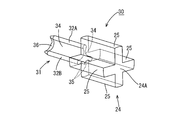
- the second embodiment differs from the first embodiment in the shape of the insertion portion 31 of the hot melt block 30.
- Other configurations are the same as those of the first embodiment, and therefore, the same components as those of the first embodiment are denoted by the same reference numerals and description thereof is omitted.
- the hot melt block 30 includes an insertion portion 31 that can be inserted between the plurality of electric wires 11 and 12 surrounded by the terminal 16A of the sheath 16 and a spacer portion 24.
- the insertion portion 31 includes a first insertion wall 32A that partitions between the electric wires 11 and 12 surrounded by the sheath 16, and a second insertion wall 32B that extends in a direction intersecting with the first insertion wall 32A.
- the distal end of the first insertion wall 32A and the distal end of the second insertion wall 32B are connected via a concave surface 34 along the outer peripheral surface of each electric wire 11.
- the lower surface of the second insertion wall 32B is formed with a pair of concave surfaces 35 along the outer peripheral surfaces of the pair of electric wires 12.
- the distal end portions of the first insertion wall 32A, the second insertion wall 32B, and the concave surfaces 34 and 35 are tapered portions 36 whose thickness is gradually reduced toward the front.
- the positioning accuracy of the insertion portion 31 can be enhanced by the insertion walls 32A and 32B that partition between the adjacent electric wires 11 and 12.
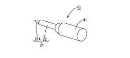
- the third embodiment differs from the first embodiment in the shape of the spacer 41 of the hot melt block 40.
- Other configurations are the same as those of the first embodiment, and therefore, the same components as those of the first embodiment are denoted by the same reference numerals and description thereof is omitted.
- the hot melt block 40 includes the insertion portion 21 and a spacer portion 41 fixed to the insertion portion 21 and disposed between the plurality of electric wires 11 and 12 drawn rearward in the terminal 16 ⁇ / b> A of the sheath 16.
- the spacer portion 41 has a columnar shape, and has a tapered outer peripheral surface at an end on the front side. The axis of the spacer portion 41 is arranged at the center between the plurality of electric wires 11 and 12 drawn rearward in the terminal 16A.
- the fourth embodiment differs from the third embodiment in that a projecting portion 53 is provided at the rear end of the hot melt block 50.
- Other configurations are the same as those of the third embodiment, and therefore, the same components as those of the third embodiment are denoted by the same reference numerals and description thereof is omitted.
- the spacer portion 51 of the hot melt block 50 projects in the radial direction with respect to the axial direction of the hot melt block 50 and the columnar main body 52 disposed between the plurality of wires 11 and 12 to partition the wires 11 and 12.
- An overhang 53 is provided.
- the overhanging portion 53 is a plate-like shape in which a partitioning portion 54 that partitions between the electric wires 11 and 12 extends in a cross shape in the radial direction, and is formed integrally with the rear end of the main body 52. According to the fourth embodiment, the space between the adjacent electric wires 11 and 12 can be maintained by the overhang portion 53. Further, when the hot melt block 50 is assembled, the overhang portion 53 can be used for positioning the hot melt block 50 in the front-rear direction (the direction of insertion into the heat shrinkable tube 19).
- the fifth embodiment is different from the fourth embodiment in that the shape of the projecting portion 62 of the hot melt block 60 is changed.
- Other configurations are the same as those of the fourth embodiment, and therefore, the same components as those of the fourth embodiment are denoted by the same reference numerals and description thereof is omitted.
- the spacer portion 61 of the hot melt block 60 includes a main body 52 and a projecting portion 62 projecting radially with respect to the axial direction of the hot melt block 60 to partition between the pair of electric wires 11.
- the overhang portion 62 has a rectangular plate shape and stands up (radially) from the rear end of the main body 52.
- the technology described in this specification is not limited to the embodiments described above and illustrated in the drawings.
- the following embodiments are also included in the technical scope of the technology described in this specification.
- the number of electric wires 11 and 12 is not limited to four and can be changed as appropriate.
- the cable is not limited to the cable including both the power line 11 and the signal line 12, and may be a cable including only one of the power line 11 and the signal line 12.
- the combination of the insertion portions 21, 31 and the spacer portions 24, 41, 51, 61 is not limited to the combination of the above-described embodiment, and can be appropriately changed. Further, the shapes of the insertion portion and the spacer portion can be appropriately changed. For example, the tapered portions 21A, 36 may not be formed in the insertion portions 21, 31.
Landscapes
- Engineering & Computer Science (AREA)
- Manufacturing & Machinery (AREA)
- Architecture (AREA)
- Civil Engineering (AREA)
- Structural Engineering (AREA)
- Insulated Conductors (AREA)
- Mechanical Engineering (AREA)
- Cable Accessories (AREA)
- Processing Of Terminals (AREA)
- Details Of Indoor Wiring (AREA)
- Manufacturing Of Electric Cables (AREA)
Priority Applications (2)
| Application Number | Priority Date | Filing Date | Title |
|---|---|---|---|
| US17/262,995 US12034285B2 (en) | 2018-08-07 | 2019-07-18 | Hot melt block, cable manufacturing method, and cable |
| CN201980047928.6A CN112425020A (zh) | 2018-08-07 | 2019-07-18 | 热熔块、电缆的制造方法及电缆 |
Applications Claiming Priority (2)
| Application Number | Priority Date | Filing Date | Title |
|---|---|---|---|
| JP2018148401A JP7003871B2 (ja) | 2018-08-07 | 2018-08-07 | ホットメルトブロック及びケーブルの製造方法 |
| JP2018-148401 | 2018-08-07 |
Publications (1)
| Publication Number | Publication Date |
|---|---|
| WO2020031649A1 true WO2020031649A1 (ja) | 2020-02-13 |
Family
ID=69414097
Family Applications (1)
| Application Number | Title | Priority Date | Filing Date |
|---|---|---|---|
| PCT/JP2019/028263 Ceased WO2020031649A1 (ja) | 2018-08-07 | 2019-07-18 | ホットメルトブロック、ケーブルの製造方法及びケーブル |
Country Status (4)
| Country | Link |
|---|---|
| US (1) | US12034285B2 (enExample) |
| JP (1) | JP7003871B2 (enExample) |
| CN (1) | CN112425020A (enExample) |
| WO (1) | WO2020031649A1 (enExample) |
Families Citing this family (3)
| Publication number | Priority date | Publication date | Assignee | Title |
|---|---|---|---|---|
| TWI744995B (zh) * | 2020-07-22 | 2021-11-01 | 榮晶生物科技股份有限公司 | 電子裝置 |
| CN113205929A (zh) * | 2021-05-21 | 2021-08-03 | 常州市薛巷电讯元件有限公司 | 一种带密封性的橡胶线接头的制作工艺 |
| US12007106B2 (en) * | 2022-06-20 | 2024-06-11 | Chuan-Yang Lee | Flexible wire support structure and lamp conductor-cable using same |
Citations (4)
| Publication number | Priority date | Publication date | Assignee | Title |
|---|---|---|---|---|
| JPH09161554A (ja) * | 1995-12-11 | 1997-06-20 | Yazaki Corp | 線間防水方法 |
| JP2011229200A (ja) * | 2010-04-15 | 2011-11-10 | Sumitomo Wiring Syst Ltd | グロメットの止水構造の製造方法、および、グロメットの止水構造 |
| JP2012033271A (ja) * | 2010-07-28 | 2012-02-16 | Sumitomo Wiring Syst Ltd | グロメットの止水構造の製造方法、および、グロメットの止水構造 |
| JP2012182924A (ja) * | 2011-03-02 | 2012-09-20 | Sumitomo Wiring Syst Ltd | 線間止水用のホットメルトブロックおよび該ホットメルトブロックを用いた多芯ケーブルの端末止水方法ならびに端末止水構造 |
Family Cites Families (4)
| Publication number | Priority date | Publication date | Assignee | Title |
|---|---|---|---|---|
| JP2014026783A (ja) * | 2012-07-25 | 2014-02-06 | Sumitomo Electric Ind Ltd | 絶縁電線およびその止水方法 |
| CN104716605A (zh) * | 2013-12-13 | 2015-06-17 | 淄博思科电子技术开发有限公司 | 电缆牵引装置 |
| WO2017110377A1 (ja) * | 2015-12-24 | 2017-06-29 | 株式会社オートネットワーク技術研究所 | 多芯ケーブルのシール構造、及びゴム栓 |
| KR101806320B1 (ko) * | 2016-01-18 | 2017-12-07 | 주식회사 일진콤텍 | 전선케이블의 방수 장치 |
-
2018
- 2018-08-07 JP JP2018148401A patent/JP7003871B2/ja active Active
-
2019
- 2019-07-18 WO PCT/JP2019/028263 patent/WO2020031649A1/ja not_active Ceased
- 2019-07-18 US US17/262,995 patent/US12034285B2/en active Active
- 2019-07-18 CN CN201980047928.6A patent/CN112425020A/zh active Pending
Patent Citations (4)
| Publication number | Priority date | Publication date | Assignee | Title |
|---|---|---|---|---|
| JPH09161554A (ja) * | 1995-12-11 | 1997-06-20 | Yazaki Corp | 線間防水方法 |
| JP2011229200A (ja) * | 2010-04-15 | 2011-11-10 | Sumitomo Wiring Syst Ltd | グロメットの止水構造の製造方法、および、グロメットの止水構造 |
| JP2012033271A (ja) * | 2010-07-28 | 2012-02-16 | Sumitomo Wiring Syst Ltd | グロメットの止水構造の製造方法、および、グロメットの止水構造 |
| JP2012182924A (ja) * | 2011-03-02 | 2012-09-20 | Sumitomo Wiring Syst Ltd | 線間止水用のホットメルトブロックおよび該ホットメルトブロックを用いた多芯ケーブルの端末止水方法ならびに端末止水構造 |
Also Published As
| Publication number | Publication date |
|---|---|
| US12034285B2 (en) | 2024-07-09 |
| JP2020025393A (ja) | 2020-02-13 |
| JP7003871B2 (ja) | 2022-01-21 |
| CN112425020A (zh) | 2021-02-26 |
| US20210167587A1 (en) | 2021-06-03 |
Similar Documents
| Publication | Publication Date | Title |
|---|---|---|
| US10003141B2 (en) | Seal structure for multi-core cable | |
| US20180041020A1 (en) | Seal structure for multiple-core cable | |
| JP2012182047A (ja) | バスバーセット及びその製造方法 | |
| US20040070293A1 (en) | Lead frame and distributing part using same | |
| WO2020031649A1 (ja) | ホットメルトブロック、ケーブルの製造方法及びケーブル | |
| JP2007110797A (ja) | ステータにおける給電線とターミナルの接続構造、および接合装置 | |
| JP2018510462A (ja) | シールド電気コネクタ | |
| WO2011155059A1 (ja) | 固定子および固定子の製造方法 | |
| US20170169919A1 (en) | Wire harness and method for manufacturing same | |
| KR101598046B1 (ko) | 센서 모듈 및 센서 모듈의 제조 방법 | |
| JP2010192309A (ja) | シールド線の端末止水方法および端末止水部を備えたシールド線 | |
| JP2018063763A (ja) | 導電路 | |
| US10065342B2 (en) | Molded resin-equipped electric wire and molded resin-equipped electric wire production method | |
| JP2019075883A (ja) | シールド電線の止水構造及び止水方法 | |
| JP2022003644A (ja) | 端子付電線及び端子付電線の製造方法 | |
| JP4767137B2 (ja) | シールド線の止水方法および止水構造 | |
| JP2017139151A (ja) | 熱収縮チューブ付電線 | |
| JP7207992B2 (ja) | 防水ジョイント電線の止水構造 | |
| JP6720929B2 (ja) | 導電路及びワイヤハーネス | |
| CN112514191B (zh) | 多芯电缆的止水结构 | |
| WO2018180374A1 (ja) | キャップ付き電線 | |
| JP2018064391A (ja) | ケーブルの防水構造 | |
| JP2021144803A (ja) | ワイヤハーネス | |
| JP5640907B2 (ja) | ワイヤハーネス及びワイヤハーネスの製造方法 | |
| JP2016136458A (ja) | 端子金具、ワイヤハーネス、及び端子金具の製造方法 |
Legal Events
| Date | Code | Title | Description |
|---|---|---|---|
| 121 | Ep: the epo has been informed by wipo that ep was designated in this application |
Ref document number: 19846395 Country of ref document: EP Kind code of ref document: A1 |
|
| NENP | Non-entry into the national phase |
Ref country code: DE |
|
| 122 | Ep: pct application non-entry in european phase |
Ref document number: 19846395 Country of ref document: EP Kind code of ref document: A1 |