WO2020031403A1 - リレー - Google Patents
リレー Download PDFInfo
- Publication number
- WO2020031403A1 WO2020031403A1 PCT/JP2019/006168 JP2019006168W WO2020031403A1 WO 2020031403 A1 WO2020031403 A1 WO 2020031403A1 JP 2019006168 W JP2019006168 W JP 2019006168W WO 2020031403 A1 WO2020031403 A1 WO 2020031403A1
- Authority
- WO
- WIPO (PCT)
- Prior art keywords
- movable contact
- magnet
- contact piece
- contact
- fixed
- Prior art date
- Legal status (The legal status is an assumption and is not a legal conclusion. Google has not performed a legal analysis and makes no representation as to the accuracy of the status listed.)
- Ceased
Links
Images

Classifications
-
- H—ELECTRICITY
- H01—ELECTRIC ELEMENTS
- H01H—ELECTRIC SWITCHES; RELAYS; SELECTORS; EMERGENCY PROTECTIVE DEVICES
- H01H50/00—Details of electromagnetic relays
- H01H50/16—Magnetic circuit arrangements
- H01H50/36—Stationary parts of magnetic circuit, e.g. yoke
- H01H50/38—Part of main magnetic circuit shaped to suppress arcing between the contacts of the relay
-
- H—ELECTRICITY
- H01—ELECTRIC ELEMENTS
- H01H—ELECTRIC SWITCHES; RELAYS; SELECTORS; EMERGENCY PROTECTIVE DEVICES
- H01H50/00—Details of electromagnetic relays
- H01H50/54—Contact arrangements
-
- H—ELECTRICITY
- H01—ELECTRIC ELEMENTS
- H01H—ELECTRIC SWITCHES; RELAYS; SELECTORS; EMERGENCY PROTECTIVE DEVICES
- H01H50/00—Details of electromagnetic relays
- H01H50/54—Contact arrangements
- H01H50/60—Contact arrangements moving contact being rigidly combined with movable part of magnetic circuit
-
- H—ELECTRICITY
- H01—ELECTRIC ELEMENTS
- H01H—ELECTRIC SWITCHES; RELAYS; SELECTORS; EMERGENCY PROTECTIVE DEVICES
- H01H9/00—Details of switching devices, not covered by groups H01H1/00 - H01H7/00
- H01H9/30—Means for extinguishing or preventing arc between current-carrying parts
- H01H9/44—Means for extinguishing or preventing arc between current-carrying parts using blow-out magnet
- H01H9/443—Means for extinguishing or preventing arc between current-carrying parts using blow-out magnet using permanent magnets
Definitions
- the present invention relates to a relay.
- Some relays include a magnet for extinguishing an arc generated at a contact point (see Patent Document 1).
- a magnet for extinguishing an arc generated at a contact point see Patent Document 1.
- two permanent magnets are arranged so as to face each other, and a movable contact piece is arranged between the two permanent magnets.
- Lorentz force acts on the arc due to the magnetic force of the permanent magnet.
- the arc is quickly extinguished by stretching the arc.
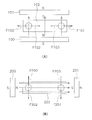
- two magnets 100 and 101 are arranged so as to face each other in the width direction of the movable contact piece (the vertical direction in FIG. 8), and these magnets 100 and 101 have opposite poles facing each other.
- a magnetic flux is generated in a direction from the magnet 100 to the magnet 101.
- the extending direction of the arc changes inward and outward in the longitudinal direction of the movable contact piece 102 (the left-right direction in FIG. 8) in accordance with the direction of conduction at the contact.
- Lorentz force acts outward of the movable contact piece 102 as shown by arrows F100 and F101.
- FIG. 8B two permanent magnets 200 and 201 are arranged so as to face each other in the longitudinal direction of the movable contact piece 202, and these magnets 200 and 201 are arranged so that different poles face each other.
- a magnetic flux is generated at the contact along the longitudinal direction of the movable contact piece 202. Therefore, the extending direction of the arc is the width direction of the movable contact piece 102.
- Lorentz force acts in the width direction of the movable contact piece 102 as shown by arrows F200 and F201.
- the movable contact piece is held by the contact piece holding portion.
- the contact piece holding portion includes, for example, a drive shaft connected to the movable contact piece.
- the contact piece holding unit moves the movable contact piece by being driven by the driving device. Therefore, wear debris may be generated due to wear between the movable contact piece and the contact piece holding member or between components of the contact piece holding portion.
- An object of the present invention is to suppress the deterioration of the current-carrying performance due to wear debris while suppressing the influence of the direction of current-carrying on arc extinguishing characteristics.
- the relay includes a first fixed contact, a second fixed contact, a movable contact piece, a contact piece holding unit, a first magnet, a second magnet, a third magnet, and a fourth magnet.
- the movable contact piece includes a first movable contact and a second movable contact arranged apart from each other in the longitudinal direction.
- the movable contact piece is provided so as to be movable in a direction in which the first movable contact and the second movable contact are in contact with and separated from the first fixed contact and the second fixed contact.
- the contact piece holding section holds the movable contact piece at a position between the first movable contact and the second movable contact in the longitudinal direction of the movable contact piece.
- the first magnet is arranged on one side of the movable contact piece in the width direction of the movable contact piece that intersects the longitudinal direction of the movable contact piece.
- the second magnet is arranged on the other side of the movable contact piece in the width direction of the movable contact piece.
- the third magnet is arranged apart from the first fixed contact and the first movable contact in the moving direction of the movable contact piece.
- the fourth magnet is arranged apart from the second fixed contact and the second movable contact in the moving direction of the movable contact piece.
- the first magnet and the second magnet are arranged so that the same poles face each other.
- the movable contact piece is disposed between the first magnet and the second magnet in the width direction of the movable contact piece.
- the third magnet is arranged to increase the magnetic flux in the longitudinal direction of the movable contact piece at a position between the first fixed contact and the first movable contact.
- the fourth magnet is arranged to increase the magnetic flux in the longitudinal direction of the movable contact piece at a position between the second fixed contact and the second movable contact.
- the first magnet and the second magnet are arranged so that the same polarity faces each other, and the movable contact piece is located between the first magnet and the second magnet in the width direction of the movable contact piece. Placed in Therefore, a magnetic flux is generated at the contact along the longitudinal direction of the movable contact piece. As a result, the influence on the arc extinguishing characteristics of the arc due to the direction of conduction is suppressed.
- the movable contact piece is disposed between the first magnet and the second magnet in the width direction of the movable contact piece. Therefore, even if the wear debris generated from the contact piece holding portion is attracted to the first magnet or the second magnet, it moves in a direction different from that of the contact. For this reason, it is possible to suppress the wear debris from being caught between the contacts, and it is possible to suppress a decrease in the current-carrying performance due to the wear debris.
- the third magnet is arranged so as to increase the magnetic flux in the longitudinal direction of the movable contact piece at a position between the first fixed contact and the first movable contact.
- the fourth magnet is arranged to increase the magnetic flux in the longitudinal direction of the movable contact piece at a position between the second fixed contact and the second movable contact.
- the relay may further include a case.
- the case may include a first storage section and a second storage section.
- the first storage section may store the first fixed contact, the second fixed contact, and the movable contact piece.
- the second storage section may be partitioned from the first storage section.
- At least one of the third magnet and the fourth magnet may be arranged in the second housing. In this case, it is possible to suppress the wear debris from adhering to the third magnet and / or the fourth magnet.
- the relay may further include a first partition disposed between the first fixed contact and the third magnet. In this case, the attachment of the wear debris to the third magnet can be suppressed by the first partition.
- the relay may further include a second partition disposed between the second fixed contact and the fourth magnet. In this case, the attachment of the wear debris to the fourth magnet can be suppressed by the second partition.
- the first fixed contact may be disposed between the first movable contact and the third magnet in the moving direction of the movable contact piece.
- the third magnet can be arranged so as to increase the magnetic flux in the longitudinal direction of the movable contact piece at a position between the first fixed contact and the first movable contact. Further, since the first fixed contact does not move, the third magnet can be arranged close to the first fixed contact.
- the second fixed contact may be arranged between the second movable contact and the fourth magnet in the moving direction of the movable contact piece.
- the fourth magnet can be arranged so as to increase the magnetic flux in the longitudinal direction of the movable contact piece at a position between the second fixed contact and the second movable contact. Further, since the second fixed contact does not move, the fourth magnet can be arranged close to the second fixed contact.
- the movable contact piece may be arranged between the first fixed contact and the third magnet in the moving direction of the movable contact piece.
- the third magnet can be arranged so as to increase the magnetic flux in the longitudinal direction of the movable contact piece at a position between the first fixed contact and the first movable contact.
- the movable contact piece may be arranged between the second fixed contact and the fourth magnet in the moving direction of the movable contact piece.
- the fourth magnet can be arranged so as to increase the magnetic flux in the longitudinal direction of the movable contact piece at a position between the second fixed contact and the second movable contact.
- the third magnet may overlap the first fixed contact or the first movable contact.
- the third magnet can effectively increase the magnetic flux in the longitudinal direction of the movable contact piece at a position between the first fixed contact and the first movable contact.
- the fourth magnet When viewed from the moving direction of the movable contact piece, at least a part of the fourth magnet may overlap with the second fixed contact or the second movable contact. In this case, the magnetic flux in the longitudinal direction of the movable contact piece at the position between the second fixed contact and the second movable contact can be effectively increased by the fourth magnet.
- the length of the first magnet in the longitudinal direction of the movable contact piece may be smaller than the distance between the first movable contact and the second movable contact in the longitudinal direction of the movable contact piece. In this case, even if the wear debris generated from the contact piece holding portion is attracted to the first magnet, the wear debris is prevented from approaching the first movable contact or the second movable contact. As a result, it is possible to suppress a decrease in the current-carrying performance due to wear debris.
- the length of the second magnet in the longitudinal direction of the movable contact piece may be smaller than the distance between the first movable contact and the second movable contact in the longitudinal direction of the movable contact piece. In this case, even if the wear debris generated from the contact piece holding portion is attracted to the second magnet, the wear debris is prevented from approaching the first movable contact or the second movable contact. As a result, it is possible to suppress a decrease in the current-carrying performance due to wear debris.
- the present invention it is possible to suppress a decrease in the current-carrying performance due to wear debris while suppressing the effect of the direction of current-carrying on arc extinguishing characteristics.
- FIG. 4 is an enlarged view showing a part of FIG. 3. It is a figure showing arrangement of the 3rd magnet and the 4th magnet concerning a 1st modification. It is a figure showing arrangement of the 3rd magnet and the 4th magnet concerning a 2nd modification. It is a mimetic diagram showing arrangement of a contact and a magnet concerning a related art.
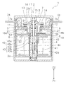
- FIG. 1 is a side sectional view showing a relay 1 according to the embodiment.
- the relay 1 includes a case 2, a contact device 3, and a driving device 4.
- the directions of up, down, left, and right mean the directions of up, down, left, and right in FIG.
- the front-back direction means a direction perpendicular to the paper surface of FIG.
- the definition of these directions does not limit the arrangement direction of the relay 1.
- the case 2 houses the contact device 3 and the driving device 4.
- the case 2 is formed of an insulating resin.
- the case 2 includes a case main body 2a and a lid 2b.
- the contact device 3 and the driving device 4 are arranged in the case main body 2a.
- the lid 2b is separate from the case body 2a.
- the lid 2b is attached to the case body 2a.
- the case main body 2 a includes a contact case 18 and an outer case 19.
- the contact case 18 partitions the inside of the case 2 into a first storage section S1 and a second storage section S2.
- the contact device 3 is arranged in the first storage section S1.
- the driving device 4 is disposed in the second storage section S2.
- the outer case 19 houses the contact case 18 therein.
- the contact device 3 includes a first fixed terminal 5, a second fixed terminal 6, a movable contact piece 7, and a contact piece holding section 8.
- the first fixed terminal 5, the second fixed terminal 6, and the movable contact piece 7 are formed of a conductive material such as copper.
- the first fixed terminal 5 includes a first fixed contact 11.
- the second fixed terminal 6 includes a second fixed contact 12.
- the first fixed contact 11 and the second fixed contact 12 are arranged apart from each other in the left-right direction.
- the movable contact piece 7 extends in the left-right direction.
- the longitudinal direction of the movable contact piece 7 coincides with the left-right direction.
- the movable contact piece 7 includes a first movable contact 13 and a second movable contact 14.
- the first movable contact 13 and the second movable contact 14 are arranged apart from each other in the left-right direction.
- the first movable contact 13 is arranged to face the first fixed contact 11.
- the second movable contact 14 is arranged to face the second fixed contact 12.
- the movable contact piece 7 includes a first end 7a and a second end 7b.
- the first end 7a is one end of the movable contact piece 7 in the left-right direction.
- the second end 7b is the other end of the movable contact piece 7 in the left-right direction.
- the first end 7 a is the left end of the movable contact piece 7.
- the second end 7 b is the right end of the movable contact piece 7.
- the first movable contact 13 is disposed between the center of the movable contact piece 7 in the left-right direction and the first end 7a.
- the second movable contact 14 is disposed between the center of the movable contact piece 7 in the left-right direction and the second end 7b.
- the movable contact piece 7 is arranged so as to be movable in the vertical direction. Specifically, the movable contact piece 7 is arranged so as to be movable in the contact direction Z1 and the separation direction Z2.
- the contact direction Z1 is a direction in which the first movable contact 13 and the second movable contact 14 contact the first fixed contact 11 and the second fixed contact 12 (downward in FIG. 1).
- the separation direction Z2 is a direction in which the first movable contact 13 and the second movable contact 14 are separated from the first fixed contact 11 and the second fixed contact 12 (upward in FIG. 1).
- the contact piece holding section 8 holds the movable contact piece 7.
- the contact piece holding section 8 holds the movable contact piece 7 at the center of the movable contact piece 7 in the left-right direction. Therefore, the contact piece holding section 8 holds the movable contact piece 7 at a position between the first movable contact 13 and the second movable contact 14 in the left-right direction.
- the contact piece holding section 8 includes a drive shaft 15, a holder 16, and a contact spring 17.
- the drive shaft 15, the holder 16, and the contact spring 17 are made of metal such as stainless steel, for example.
- the drive shaft 15, the holder 16, and the contact spring 17 may be made of a metal other than stainless steel.
- a part of the contact piece holding portion 8 may be made of a material other than metal such as resin.
- the drive shaft 15 extends vertically.
- the drive shaft 15 is arranged movably in the contact direction Z1 and the separation direction Z2.
- the holder 16 is connected to the movable contact piece 7 and holds the movable contact piece 7.
- the contact spring 17 is arranged between the drive shaft 15 and the holder 16.
- the drive shaft 15 is connected to a holder 16 via a contact spring 17.
- the first fixed terminal 5 includes a first contact support part 21 and a first external connection part 24.
- the first contact support 21 supports the first fixed contact 11 in the case 2.
- the first external connection part 24 is connected to the first contact support part 21.
- the first external connection portion 24 protrudes outside the case 2.
- the first external connection part 24 may be formed integrally with the first contact support part 21. Alternatively, the first external connection section 24 may be separate from the first contact support section 21.
- the second fixed terminal 6 includes a second contact support part 31 and a second external connection part 34.
- the second contact support portion 31 supports the second fixed contact 12 in the case 2.
- the second external connection part 34 is connected to the second contact support part 31.
- the second external connection portion 34 projects outside the case 2.
- the second external connection part 34 may be formed integrally with the second contact support part 31. Alternatively, the second external connection part 34 may be separate from the second contact support part 31.
- the driving device 4 generates a driving force for operating the movable contact piece 7.
- the driving device 4 operates the movable contact piece 7 by an electromagnetic force.
- the driving device 4 is arranged below the movable contact piece 7.
- the driving device 4 includes a coil 41, a spool 42, an iron core 43, a return spring 44, and a yoke 45.
- the coil 41 is wound around a spool 42.
- the coil 41 and the spool 42 are arranged coaxially with the drive shaft 15.
- the spool 42 includes a hole 42a penetrating the spool 42 in the axial direction.
- the iron core 43 and the return spring 44 are inserted into the hole 42a of the spool 42.
- the yoke 45 is connected to the iron core 43.
- the yoke 45 includes a first yoke 45a and a second yoke 45b.
- the first yoke 45a is disposed between the contact device 3 and the spool 42.
- the second yoke 45b is connected to the first yoke 45a.
- the second yoke 45b has a U-shape.
- the second yokes 45b are arranged on both sides of the coil 41 and on the side opposite to the first yoke 45a with respect to the coil 41.
- the core 43 includes a fixed core 43a, a movable core 43b, and a ring core 43c.
- the fixed core 43a is fixed to the second yoke 45b.
- the ring core 43c is in contact with the first yoke 45a.
- the movable core 43b is separate from the fixed core 43a and the ring core 43c.
- the movable iron core 43b is arranged movably in the contact direction Z1 and the separation direction Z2.
- the movable core 43b moves within the ring core 43c.
- the movable iron core 43b is connected to the drive shaft 15.
- the return spring 44 is disposed between the movable iron core 43b and the fixed iron core 43a. The return spring 44 urges the movable iron core 43b in the separating direction Z2.
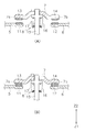
- FIG. 2 is a diagram illustrating the operation of the movable contact piece 7.
- the driving shaft 15 is pressed in the separating direction Z2 by the elastic force of the return spring 44 together with the movable iron core 43b. Therefore, the movable contact piece 7 is also pressed in the separating direction Z2, and the first movable contact 13 and the second movable contact 14 are opened from the first fixed contact 11 and the second fixed contact 12, as shown in FIG. 2A. It is in the open state when it is released.
- the driving shaft 15 When the current to the coil 41 is stopped and demagnetized, the driving shaft 15 is pressed in the separating direction Z2 by the elastic force of the return spring 44 together with the movable iron core 43b. Therefore, the first movable contact 13 and the second movable contact 14 return to the open state as shown in FIG. 2A when the movable contact piece 7 is also pressed in the separating direction Z2.
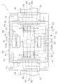
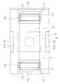
- FIG. 3 is a plan view showing a configuration inside the contact case 18 of the relay 1.
- the positions of the movable contact piece 7 and the contact piece holding portion 8 are indicated by two-dot lines.
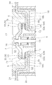
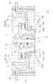
- FIG. 4 is an enlarged side sectional view showing a part of the relay 1.
- the relay 1 includes a first magnet 51, a second magnet 52, a third magnet 53, and a fourth magnet 54.
- the first to fourth magnets 51 to 54 are permanent magnets for extinguishing an arc generated between the contacts.
- the first magnet 51 and the second magnet 52 are arranged apart from each other in the front-back direction. In the present embodiment, the front-rear direction coincides with the width direction of the movable contact piece 7 that intersects the longitudinal direction of the movable contact piece 7.
- the first magnet 51 is arranged on one side in the front-back direction with respect to the movable contact piece 7.
- the second magnet 52 is disposed on the other side in the front-rear direction with respect to the movable contact piece 7.
- the movable contact piece 7 is disposed between the first magnet 51 and the second magnet 52 in the front-back direction.
- the length of the first magnet 51 in the left-right direction is smaller than the distance between the first movable contact 13 and the second movable contact 14 in the left-right direction.
- the length of the second magnet 52 in the left-right direction is smaller than the distance between the first movable contact 13 and the second movable contact 14 in the left-right direction.
- the first magnet 51 and the second magnet 52 are arranged so that the same polarity faces each other. More specifically, the first magnet 51 includes a first surface 51N facing the movable contact piece 7, and a second surface 51S opposite to the first surface 51N.
- the second magnet 52 includes a first surface 52N facing the movable contact piece 7, and a second surface 52S opposite to the first surface 52N.
- the first surface 51N of the first magnet 51 and the first surface 52N of the second magnet 52 both have N poles.
- the second surface 51S of the first magnet 51 and the second surface 52S of the second magnet 52 are both S poles.
- the relay 1 includes a first yoke 55 and a second yoke 56.
- the first yoke 55 and the second yoke 56 surround the movable contact piece 7 in the front-rear direction and the left-right direction when viewed from the axial direction of the drive shaft 15, that is, from the vertical direction. Thereby, the strength of the resin contact case 18 can be improved.
- the first yoke 55 includes a first portion 61, a second portion 62, and a third portion 63.
- the first yoke 55 has a shape that is bent between the first part 61 and the second part 62 and between the second part 62 and the third part 63.
- the first portion 61 and the third portion 63 extend along the left-right direction.
- the second portion 62 extends along the front-back direction.
- the first portion 61 faces the second surface 51S of the first magnet 51.
- the second portion 62 faces the first end 7 a of the movable contact piece 7.
- the third portion 63 faces the second surface 52S of the second magnet 52.
- the second yoke 56 includes a fourth portion 64, a fifth portion 65, and a sixth portion 66.
- the first yoke 55 has a bent shape between the fourth portion 64 and the fifth portion 65 and between the fifth portion 65 and the sixth portion 66.
- the fourth portion 64 and the sixth portion 66 extend in the left-right direction.
- the fifth portion 65 extends along the front-back direction.
- the fourth portion 64 faces the second surface 51S of the first magnet 51.
- the fifth portion 65 faces the second end 7 b of the movable contact piece 7.
- the sixth portion 66 faces the second surface 52S of the second magnet 52.
- the third magnet 53 is disposed apart from the first fixed contact 11 and the first movable contact 13 in the vertical direction.
- the fourth magnet 54 is disposed apart from the second fixed contact 12 and the second movable contact 14 in the vertical direction. More specifically, the third magnet 53 is arranged to be separated downward from the first fixed contact 11 and the first movable contact 13.
- the fourth magnet 54 is arranged to be separated downward from the second fixed contact 12 and the second movable contact 14.
- the first fixed contact 11 is disposed between the first movable contact 13 and the third magnet 53 in the up-down direction.
- the second fixed contact 12 is arranged between the second movable contact 14 and the fourth magnet 54 in the vertical direction.
- FIG. 5 is an enlarged view of FIG. As shown in FIG. 5, at least a part of the third magnet 53 overlaps the first fixed contact 11 and the first movable contact 13 when viewed from above and below. When viewed from above and below, at least a part of the fourth magnet 54 overlaps the second fixed contact 12 and the second movable contact 14.
- the contact case 18 includes a first partition 18a and a second partition 18b.
- the first partition 18a is disposed between the first fixed contact 11 and the third magnet 53.
- the first fixed contact 11 is arranged between the first movable contact 13 and the first partition 18a.
- the first partition 18a supports the first contact support 21.
- the second partition 18b is disposed between the second fixed contact 12 and the fourth magnet 54.
- the second fixed contact 12 is arranged between the second movable contact 14 and the second partition 18b.
- the second partition 18b supports the second contact support 31.
- the third magnet 53 generates a magnetic flux B5 in the same direction as the magnetic fluxes B1 and B2 by the first magnet 51 and the second magnet 52 at a position between the first fixed contact 11 and the first movable contact 13. Are located. That is, the third magnet 53 is arranged so as to generate the magnetic flux B5 in the left-right direction at a position between the first fixed contact 11 and the first movable contact 13. Therefore, by combining with the magnetic fluxes B1 and B2 of the first magnet 51 and the second magnet 52, the third magnet 53 generates a magnetic flux in the left-right direction at a position between the first fixed contact 11 and the first movable contact 13. Increase.
- the fourth magnet 54 generates a magnetic flux B6 in the same direction as the magnetic fluxes B3 and B4 by the first magnet 51 and the second magnet 52 at a position between the second fixed contact 12 and the second movable contact 14. Are located. That is, the fourth magnet 54 is arranged so as to generate the magnetic flux B6 in the left-right direction at a position between the second fixed contact 12 and the second movable contact 14. Therefore, by combining with the magnetic fluxes B3 and B4 of the first magnet 51 and the second magnet 52, the fourth magnet 54 generates a magnetic flux in the left-right direction at a position between the second fixed contact 12 and the second movable contact 14. Increase.
- the third magnet 53 includes a first surface 53S and a second surface 53N.
- the first surface 53S and the second surface 53N are end surfaces of the third magnet 53 in the vertical direction.
- the first surface 53S is arranged facing the first fixed contact 11 side.
- the second surface 52N is arranged facing the opposite side of the first fixed contact 11.
- the fourth magnet 54 includes a first surface 54S and a second surface 54N.
- the first surface 54S and the second surface 54N are end surfaces of the fourth magnet 54 in the vertical direction.
- the first surface 54S is arranged facing the second fixed contact 12 side.
- the fourth surface is arranged facing the side opposite to the second fixed contact 12.
- the first surface 53S of the third magnet 53 and the first surface 54S of the fourth magnet 54 are both S poles.
- the second surface 53N of the third magnet 53 and the second surface 54N of the fourth magnet 54 both have N poles.
- a magnetic flux B ⁇ b> 6 traveling in the left-right direction between the second fixed contact 12 and the second movable contact 14 is generated by the fourth magnet 54. More specifically, the magnetic flux B5 in the direction from the center in the left-right direction toward the first end 7a in the movable contact piece 7 is generated by the third magnet 53 between the first fixed contact 11 and the first movable contact 13. Is done.
- a magnetic flux B ⁇ b> 6 from the center in the left-right direction toward the second end 7 b in the movable contact piece 7 is generated by the fourth magnet 54 between the second fixed contact 12 and the second movable contact 14.
- the first magnet 51 and the second magnet 52 are disposed so that the same polarity faces each other, and the movable contact piece 7 and the first magnet 51 It is arranged between the two magnets 52. Therefore, magnetic fluxes B1 and B2 are generated between the first fixed contact 11 and the first movable contact 13 along the left-right direction. Further, magnetic fluxes B3 and B4 are generated between the second fixed contact 12 and the second movable contact 14 along the left-right direction. Thereby, when a current flows from the left to the right in the movable contact piece 7, a Lorentz force acts in the front-rear direction as shown by arrows F1 and F2 in FIG.
- the movable contact piece 7 is disposed between the first magnet 51 and the second magnet 52 in the front-back direction. Therefore, even if the wear debris generated from the contact piece holding portion 8 is attracted to the first magnet 51 or the second magnet 52, the debris moves in a direction different from that of the contact 11-14. For this reason, it is possible to suppress the wear debris from being caught between the contacts 11 to 14, and it is possible to suppress a decrease in the current-carrying performance due to the wear debris.
- the third magnet 53 is arranged so as to increase the magnetic flux in the left-right direction at a position between the first fixed contact 11 and the first movable contact 13.
- the fourth magnet 54 is arranged at a position between the second fixed contact 12 and the second movable contact 14 so as to increase the magnetic flux in the left-right direction.
- the third magnet 53 and the fourth magnet 54 are arranged in the second storage section S2.
- the first partition 18a is arranged between the first fixed contact 11 and the third magnet 53.
- a second partition 18b is arranged between the second fixed contact 12 and the fourth magnet 54. Therefore, it is possible to suppress the wear debris from adhering to the third magnet 53 and the fourth magnet 54.
- the first fixed contact 11 is disposed between the first movable contact 13 and the third magnet 53 in the up-down direction. Since the first fixed contact 11 does not move, the third magnet 53 can be arranged close to the first fixed contact 11. Further, the second fixed contact 12 is disposed between the second movable contact 14 and the fourth magnet 54 in the up-down direction. Since the second fixed contact 12 does not move, the fourth magnet 54 can be arranged close to the second fixed contact 12.
- the length of the first magnet 51 in the left-right direction is smaller than the distance between the first movable contact 13 and the second movable contact 14 in the left-right direction. Therefore, both ends of the first magnet 51 in the left-right direction can be arranged apart from the first movable contact 13 and the second movable contact 14. Therefore, even if the wear debris generated from the contact piece holding portion 8 is attracted to the first magnet 51, the wear debris is prevented from approaching the first movable contact 13 or the second movable contact 14. As a result, it is possible to suppress a decrease in the current-carrying performance due to wear debris.
- the length of the second magnet 52 in the left-right direction is smaller than the distance between the first movable contact 13 and the second movable contact 14 in the left-right direction. Therefore, both ends of the second magnet 52 in the left-right direction can be arranged apart from the first movable contact 13 and the second movable contact 14. Therefore, even if the wear debris generated from the contact piece holding portion 8 is attracted to the second magnet 52, the wear debris is prevented from approaching the first movable contact 13 or the second movable contact 14. As a result, it is possible to suppress a decrease in the current-carrying performance due to wear debris.
- the present invention is not limited to the above embodiment, and various changes can be made without departing from the gist of the invention.
- the configuration of the driving device 4 may be changed.
- the shape or arrangement of the coil 41, the spool 42, the iron core 43, the return spring 44, or the yoke 45 may be changed.
- the shape or arrangement of the case 2 may be changed.
- the movable contact piece 7 moves in the contact direction Z1 by the drive device 4 pulling the drive shaft 15 toward the coil 41.
- the driving device 4 pushes the driving shaft 15 from the coil 41 side
- the movable contact piece 7 moves in the separating direction Z2.
- the movable contact piece 7 may move in the separating direction Z2 by the drive device 4 pulling the drive shaft 15 toward the coil 41.
- the movable contact piece 7 may move in the contact direction Z1 by the drive device 4 pushing the drive shaft 15 from the coil 41 side. That is, the contact direction Z1 and the separation direction Z2 may be upside down in the above embodiment.
- the shape or arrangement of the first fixed terminal 5, the second fixed terminal 6, and the movable contact piece 7 may be changed.
- the first fixed terminal 5 may have a shape bent from the first contact support 21 toward the coil 41.
- the second fixed terminal 6 may be bent from the second contact support 31 toward the coil 41.
- the first fixed contact 11 may be separate from the first fixed terminal 5 or may be integrated with the first fixed terminal 5.
- the second fixed contact 12 may be separate from or integral with the second fixed terminal 6.
- the first movable contact 13 may be separate from the movable contact piece 7 or may be integrated.
- the second movable contact 14 may be separate from the movable contact piece 7 or may be integrated.
- FIG. 6 is a diagram illustrating an arrangement of the third magnet 53 and the fourth magnet 54 according to the first modification.
- the third magnet 53 includes a first surface 53S and a second surface 53N.
- the first surface 53S and the second surface 53N are end surfaces of the third magnet 53 in the left-right direction.
- the first surface 53S is the left end surface of the third magnet 53.
- the second surface 53N is a right end surface of the third magnet 53.
- the fourth magnet 54 includes a first surface 54S and a second surface 54N.
- the first surface 54S and the second surface 54N are end surfaces of the fourth magnet 54 in the left-right direction.
- the first surface 54S is a right end surface of the fourth magnet 54.
- the second surface 54N is a left end surface of the fourth magnet 54.
- the first surface 53S of the third magnet 53 and the first surface 54S of the fourth magnet 54 are both S poles.
- the second surface 53N of the third magnet 53 and the second surface 54N of the fourth magnet 54 both have N poles.
- the magnetic flux in the direction from the center of the movable contact piece 7 in the left-right direction toward the first end 7a. Is generated by the third magnet 53 between the first fixed contact 11 and the first movable contact 13.
- a magnetic flux from the center of the movable contact piece 7 toward the second end 7b in the left-right direction is generated by the fourth magnet 54 between the second fixed contact 12 and the second movable contact 14.
- the arrangement of the first to fourth magnets 51 to 54 is not limited to the above-described embodiment, and may be changed.
- the third magnet 53 and the fourth magnet 54 may be arranged in the first housing part S1.
- FIG. 7 is a diagram illustrating an arrangement of the third magnet 53 and the fourth magnet 54 according to the second modification.
- the third magnet 53 and the fourth magnet 54 may be arranged above the movable contact piece 7.
- the movable contact piece 7 may be arranged between the first fixed contact 11 and the third magnet 53 in the vertical direction.
- the movable contact piece 7 may be arranged between the second fixed contact 12 and the fourth magnet 54 in the vertical direction.
- one of the third magnet 53 and the fourth magnet 54 is disposed on the movable contact piece 7, and the other of the third magnet 53 and the fourth magnet 54 is connected to the first fixed contact 11 or the second fixed contact 12. It may be arranged below.
- the present invention it is possible to suppress a decrease in the current-carrying performance due to wear debris while suppressing the effect of the direction of current-carrying on arc extinguishing characteristics.
Landscapes
- Physics & Mathematics (AREA)
- Electromagnetism (AREA)
- Arc-Extinguishing Devices That Are Switches (AREA)
Abstract
第1磁石(51)と第2磁石(52)とは、互いに同極が向き合うように配置される。可動接触片(7)は、可動接触片(7)の幅方向において、第1磁石(51)と第2磁石(52)との間に配置される。第3磁石(53)は、第1固定接点(11)と第1可動接点(13)との間の位置で可動接触片(7)の長手方向への磁束を増大させるように配置される。第4磁石(54)は、第2固定接点(12)と第2可動接点(14)との間の位置で可動接触片(7)の長手方向への磁束を増大させるように配置される。
Description
本発明はリレーに関する。
リレーには、接点に発生するアークを消弧するための磁石を備えるものがある(特許文献1参照)。例えば,互いに対向するように2つの永久磁石が配置され、可動接触片が、それら2つの永久磁石の間に配置される。接点間においてアークが発生すると、アークには、永久磁石の磁力によってローレンツ力が作用する。それにより、アークが引き伸ばされることで迅速に消弧される。
例えば、図8Aでは、2つの磁石100,101が、可動接触片の幅方向(図8の上下方向)に互いに対向して配置され、これらの磁石100,101は、互いに異極が対向するように配置されている。この場合、磁石100から磁石101に向かう方向に磁束が生じる。この場合、接点での通電方向に応じて、アークの引き伸ばし方向が、可動接触片102の長手方向(図8の左右方向)において内方と外方とに変化する。例えば、可動接触片102においてある方向に電流が流れるときには、矢印F100,F101のように可動接触片102の外方に向かって、ローレンツ力が作用する。また、逆方向に電流が流れるときには、矢印F102,F103のように、可動接触片102の内方に向かって、ローレンツ力が作用する。そのため、接点での通電方向に応じて、アークの消弧特性に差が生じてしまう。
一方、図8Bでは、可動接触片202の長手方向に互いに対向するように2つの永久磁石200,201が配置され、これらの磁石200,201は互いに異極が対向するように配置されている。この場合、図8Bに示すように、接点において可動接触片202の長手方向に沿って磁束が生じる。そのため、アークの引き伸ばし方向は、可動接触片102の幅方向となる。例えば、可動接触片202においてある方向に電流が流れるときには、矢印F200,F201のように、可動接触片102の幅方向に向かってローレンツ力が作用する。また、逆方向に電流が流れるときには、矢印F202,F203のように、可動接触片102の幅方向に向かってローレンツ力が作用する。この場合、通電方向によるアークの消弧特性への影響は少ない。
しかし、リレーでは、可動接触片は接触片保持部によって保持されている。接触片保持部は、例えば可動接触片に接続される駆動軸を含む。接触片保持部は、駆動装置によって駆動されることで、可動接触片を移動させる。そのため、可動接触片と接触片保持部材との間、或いは、接触片保持部の構成部品の間の磨耗により、磨耗屑が発生することがある。
図8Bのように磁石が配置されている場合、接触片保持部において発生した磨耗屑が、磁石によって引き付けられると、磨耗屑は接点に向かって移動する。そのため、磨耗屑が、接点の間に挟まることがある。この場合、接点間の接触抵抗が大きくなり、通電性能が低下する可能性がある。
本発明の目的は、通電方向によるアークの消弧特性への影響を抑えながら、磨耗屑による通電性能の低下を抑えることにある。
一態様に係るリレーは、第1固定接点と、第2固定接点と、可動接触片と、接触片保持部と、第1磁石と、第2磁石と、第3磁石と、第4磁石とを含む。可動接触片は、長手方向に互いに離れて配置された第1可動接点と第2可動接点とを含む。可動接触片は、第1可動接点及び第2可動接点が第1固定接点及び第2固定接点に対して接触する方向及び開離する方向に移動可能に設けられる。接触片保持部は、可動接触片の長手方向において、第1可動接点と第2可動接点との間の位置において、可動接触片を保持する。
第1磁石は、可動接触片の長手方向と交差する可動接触片の幅方向において、可動接触片の一側方に配置される。第2磁石は、可動接触片の幅方向において可動接触片の他側方に配置される。第3磁石は、可動接触片の移動方向において第1固定接点及び第1可動接点から離れて配置される。第4磁石は、可動接触片の移動方向において第2固定接点及び第2可動接点から離れて配置される。
第1磁石と第2磁石とは、互いに同極が向き合うように配置される。可動接触片は、可動接触片の幅方向において、第1磁石と第2磁石との間に配置される。第3磁石は、第1固定接点と第1可動接点との間の位置における可動接触片の長手方向への磁束を増大させるように配置される。第4磁石は、第2固定接点と第2可動接点との間の位置における可動接触片の長手方向への磁束を増大させるように配置される。
本態様に係るリレーでは、第1磁石と第2磁石とは、互いに同極が向き合うように配置され、可動接触片は、可動接触片の幅方向において、第1磁石と第2磁石との間に配置される。そのため、接点において可動接触片の長手方向に沿って磁束が生じる。それにより、通電方向によるアークの消弧特性への影響が抑えられる。
また、可動接触片は、可動接触片の幅方向において、第1磁石と第2磁石との間に配置される。従って、接触片保持部から生じた磨耗屑が第1磁石或いは第2磁石に引き付けられても、接点とは異なる方向に向かって移動する。そのため、磨耗屑が接点の間に挟まることが抑えられ、磨耗屑による通電性能の低下を抑えることができる。
さらに、第3磁石は、第1固定接点と第1可動接点との間の位置における可動接触片の長手方向への磁束を増大させるように配置される。第4磁石は、第2固定接点と第2可動接点との間の位置における可動接触片の長手方向への磁束を増大させるように配置される。それにより、アークの消弧特性を向上させることができる。また、接触片保持部から生じた磨耗屑が第3磁石或いは第4磁石に引き付けられても、接点とは異なる方向に向かって移動する。そのため、磨耗屑が接点の間に挟まることが抑えられ、磨耗屑による通電性能の低下を抑えることができる。
リレーは、ケースをさらに含んでもよい。ケースは、第1収納部と第2収納部とを含んでもよい。第1収納部は、第1固定接点と第2固定接点と可動接触片とを収納してもよい。第2収納部は、第1収納部から区画されてもよい。第3磁石及び第4磁石の少なくとも一方は、第2収納部内に配置されてもよい。この場合、第3磁石、及び/又は、第4磁石に磨耗屑が付着することを抑えることができる。
リレーは、第1固定接点と第3磁石との間に配置される第1隔壁をさらに含んでもよい。この場合、第3磁石に磨耗屑が付着することを第1隔壁によって抑えることができる。
リレーは、第2固定接点と第4磁石との間に配置される第2隔壁をさらに備えてもよい。この場合、第4磁石に磨耗屑が付着することを第2隔壁によって抑えることができる。
第1固定接点は、可動接触片の移動方向において、第1可動接点と第3磁石との間に配置されてもよい。この場合、第3磁石を、第1固定接点と第1可動接点との間の位置における可動接触片の長手方向への磁束を増大させるように配置することができる。また、第1固定接点は移動しないので、第3磁石を第1固定接点に近接して配置することができる。
第2固定接点は、可動接触片の移動方向において、第2可動接点と第4磁石との間に配置されてもよい。この場合、第4磁石を、第2固定接点と第2可動接点との間の位置における可動接触片の長手方向への磁束を増大させるように配置することができる。また、第2固定接点は移動しないので、第4磁石を第2固定接点に近接して配置することができる。
可動接触片は、可動接触片の移動方向において、第1固定接点と第3磁石との間に配置されてもよい。この場合、第3磁石を、第1固定接点と第1可動接点との間の位置における可動接触片の長手方向への磁束を増大させるように配置することができる。
可動接触片は、可動接触片の移動方向において、第2固定接点と第4磁石との間に配置されてもよい。この場合、第4磁石を、第2固定接点と第2可動接点との間の位置における可動接触片の長手方向への磁束を増大させるように配置することができる。
可動接触片の移動方向から見て、第3磁石の少なくとも一部は、第1固定接点又は第1可動接点と重なってもよい。この場合、第3磁石によって、第1固定接点と第1可動接点との間の位置における可動接触片の長手方向への磁束を効果的に増大させることができる。
可動接触片の移動方向から見て、第4磁石の少なくとも一部は、第2固定接点又は第2可動接点と重なってもよい。この場合、第4磁石によって、第2固定接点と第2可動接点との間の位置における可動接触片の長手方向への磁束を効果的に増大させることができる。
可動接触片の長手方向における第1磁石の長さは、可動接触片の長手方向における第1可動接点と第2可動接点との間の距離より小さくてもよい。この場合、接触片保持部から生じた磨耗屑が第1磁石に引き付けられても、磨耗屑が第1可動接点或いは第2可動接点に近づくことが抑えられる。それにより、磨耗屑による通電性能の低下を抑えることができる。
可動接触片の長手方向における第2磁石の長さは、可動接触片の長手方向における第1可動接点と第2可動接点との間の距離より小さくてもよい。この場合、接触片保持部から生じた磨耗屑が第2磁石に引き付けられても、磨耗屑が第1可動接点或いは第2可動接点に近づくことが抑えられる。それにより、磨耗屑による通電性能の低下を抑えることができる。
本発明によれば、通電方向によるアークの消弧特性への影響を抑えながら、磨耗屑による通電性能の低下を抑えることができる。
以下、図面を参照して実施形態に係るリレー1について説明する。図1は実施形態に係るリレー1を示す側面断面図である。図1に示すように、リレー1は、ケース2と、接点装置3と、駆動装置4とを備える。なお、以下の説明において、上下左右の各方向は、図1における上下左右の各方向を意味するものとする。また、前後方向は、図1の紙面に垂直な方向を意味するものとする。ただし、これらの方向の定義は、リレー1の配置方向を限定するものではない。
ケース2は、接点装置3と駆動装置4とを収容している。ケース2は、絶縁性を有する樹脂で形成されている。ケース2は、ケース本体2aと蓋部2bとを含む。接点装置3と駆動装置4とは、ケース本体2a内に配置されている。蓋部2bは、ケース本体2aと別体である。蓋部2bは、ケース本体2aに取り付けられている。ケース本体2aは、接点ケース18とアウターケース19とを含む。接点ケース18は、ケース2の内部を第1収納部S1と第2収納部S2とに区画している。第1収納部S1内には、接点装置3が配置される。第2収納部S2内には、駆動装置4が配置される。アウターケース19は、接点ケース18を内部に収容している。
接点装置3は、第1固定端子5と、第2固定端子6と、可動接触片7と、接触片保持部8とを含む。第1固定端子5と、第2固定端子6と、可動接触片7とは、例えば銅などの導電性を有する材料で形成されている。第1固定端子5は、第1固定接点11を含む。第2固定端子6は、第2固定接点12を含む。第1固定接点11と第2固定接点12とは、左右方向に離れて配置されている。
可動接触片7は、左右方向に延びている。本実施形態において、可動接触片7の長手方向は、左右方向に一致する。可動接触片7は、第1可動接点13と第2可動接点14とを含む。第1可動接点13と第2可動接点14とは、左右方向に離れて配置されている。第1可動接点13は、第1固定接点11に対向して配置されている。第2可動接点14は、第2固定接点12に対向して配置されている。
可動接触片7は、第1端部7aと第2端部7bとを含む。第1端部7aは、左右方向における可動接触片7の一方の端部である。第2端部7bは、左右方向における可動接触片7の他方の端部である。本実施形態では、第1端部7aは、可動接触片7の左方の端部である。第2端部7bは、可動接触片7の右方の端部である。第1可動接点13は、左右方向における可動接触片7の中央と第1端部7aとの間に配置される。第2可動接点14は、左右方向における可動接触片7の中央と第2端部7bとの間に配置される。
可動接触片7は、上下方向に移動可能に配置されている。詳細には、可動接触片7は、接触方向Z1と開離方向Z2とに移動可能に配置されている。接触方向Z1は、第1可動接点13及び第2可動接点14が第1固定接点11及び第2固定接点12に対して接触する方向(図1における下方)である。開離方向Z2は、第1可動接点13及び第2可動接点14が第1固定接点11及び第2固定接点12から開離する方向(図1における上方)である。
接触片保持部8は、可動接触片7を保持している。接触片保持部8は、可動接触片7において左右方向の中央で可動接触片7を保持している。従って、接触片保持部8は、左右方向において第1可動接点13と第2可動接点14との間の位置において可動接触片7を保持している。
接触片保持部8は、駆動軸15と、ホルダ16と、接点バネ17とを含む。駆動軸15と、ホルダ16と、接点バネ17とは、例えばステンレスなどの金属製である。ただし、駆動軸15と、ホルダ16と、接点バネ17とは、ステンレス以外の金属製であってもよい。或いは、接触片保持部8の一部は、樹脂などの金属以外の材料製であってもよい。
駆動軸15は、上下方向に延びている。駆動軸15は、接触方向Z1及び開離方向Z2に移動可能に配置されている。ホルダ16は、可動接触片7に接続されており、可動接触片7を保持している。接点バネ17は、駆動軸15とホルダ16との間に配置されている。駆動軸15は、接点バネ17を介して、ホルダ16に接続されている。
第1固定端子5は、第1接点支持部21と第1外部接続部24とを含む。第1接点支持部21は、ケース2内において、第1固定接点11を支持している。第1外部接続部24は、第1接点支持部21に接続されている。第1外部接続部24は、ケース2の外方に突出している。第1外部接続部24は、第1接点支持部21と一体的に形成されてもよい。或いは、第1外部接続部24は、第1接点支持部21と別体であってもよい。
第2固定端子6は、第2接点支持部31と、第2外部接続部34とを含む。第2接点支持部31は、ケース2内において、第2固定接点12を支持している。第2外部接続部34は、第2接点支持部31に接続されている。第2外部接続部34は、ケース2の外方に突出している。第2外部接続部34は、第2接点支持部31と一体的に形成されてもよい。或いは、第2外部接続部34は、第2接点支持部31と別体であってもよい。
駆動装置4は、可動接触片7を動作させる駆動力を発生させる。駆動装置4は、電磁力によって可動接触片7を動作させる。駆動装置4は、可動接触片7の下方に配置されている。駆動装置4は、コイル41と、スプール42と、鉄心43と、復帰バネ44と、ヨーク45とを含む。
コイル41は、スプール42に巻回されている。コイル41及びスプール42は、駆動軸15と同軸に配置されている。スプール42は、スプール42の軸線方向に貫通する孔42aを含む。鉄心43と復帰バネ44とは、スプール42の孔42aに挿入されている。ヨーク45は、鉄心43に接続されている。
ヨーク45は、第1ヨーク45aと第2ヨーク45bとを含む。第1ヨーク45aは、接点装置3とスプール42との間に配置されている。第2ヨーク45bは、第1ヨーク45aに接続されている。第2ヨーク45bは、U字状の形状を有している。第2ヨーク45bは、コイル41の両側方と、コイル41に対して第1ヨーク45aの反対側とに配置されている。
鉄心43は、固定鉄心43aと可動鉄心43bとリング鉄心43cとを含む。固定鉄心43aは、第2ヨーク45bに固定されている。リング鉄心43cは、第1ヨーク45aに接触している。可動鉄心43bは、固定鉄心43a及びリング鉄心43cと別体である。可動鉄心43bは、接触方向Z1及び開離方向Z2に移動可能に配置されている。可動鉄心43bは、リング鉄心43c内で移動する。可動鉄心43bは、駆動軸15に接続されている。復帰バネ44は、可動鉄心43bと固定鉄心43aとの間に配置されている。復帰バネ44は、可動鉄心43bを開離方向Z2に付勢している。
次に、リレー1の動作について説明する。図2は、可動接触片7の動作を示す図である。コイル41に電流が流されず励磁されていないときには、可動鉄心43bと共に、駆動軸15は、復帰バネ44の弾性力によって開離方向Z2に押圧されている。そのため、可動接触片7も開離方向Z2に押圧されており、図2Aに示すように、第1可動接点13及び第2可動接点14は、第1固定接点11及び第2固定接点12から開離した開状態となっている。
コイル41に電流が流されて励磁されると、コイル41の電磁力により、可動鉄心43bが、復帰バネ44の弾性力に抗して、接触方向Z1に移動する。それにより、図2Bに示すように、駆動軸15とホルダ16と可動接触片7とが共に接触方向Z1に移動して、第1可動接点13及び第2可動接点14が、第1固定接点11及び第2固定接点12に接触する。
コイル41への電流が停止され消磁されると、可動鉄心43bと共に、駆動軸15は、復帰バネ44の弾性力によって開離方向Z2に押圧される。そのため、可動接触片7も開離方向Z2に押圧されることで、図2Aに示すように、第1可動接点13及び第2可動接点14は、開状態に戻る。
図3は、リレー1の接点ケース18内の構成を示す平面図である。図3では、可動接触片7及び接触片保持部8の位置が二点差線で示されている。図4は、リレー1の一部を示す拡大側面断面図である。図3及び図4に示すように、リレー1は、第1磁石51と、第2磁石52と、第3磁石53と、第4磁石54とを含む。第1~第4磁石51-54は、接点間で生じたアークを消弧するための永久磁石である。図3に示すように、第1磁石51と第2磁石52とは、前後方向に互いに離れて配置されている。なお、本実施形態において、前後方向は、可動接触片7の長手方向と交差する可動接触片7の幅方向と一致する。
第1磁石51は、可動接触片7に対して前後方向における一方に配置されている。第2磁石52は、可動接触片7に対して前後方向における他方に配置されている。言い換えれば、可動接触片7は、前後方向において、第1磁石51と第2磁石52との間に配置されている。左右方向における第1磁石51の長さは、左右方向における第1可動接点13と第2可動接点14との間の距離より小さい。左右方向における第2磁石52の長さは、左右方向における第1可動接点13と第2可動接点14との間の距離より小さい。
第1磁石51と第2磁石52とは、互いに同極が向き合うように配置されている。詳細には、第1磁石51は、可動接触片7に対向する第1面51Nと、第1面51Nの反対側の第2面51Sとを含む。第2磁石52は、可動接触片7に対向する第1面52Nと、第1面52Nの反対側の第2面52Sとを含む。第1磁石51の第1面51Nと第2磁石52の第1面52Nとは、共にN極である。第1磁石51の第2面51Sと第2磁石52の第2面52Sとは、共にS極である。
また、リレー1は、第1ヨーク55と第2ヨーク56とを含む。第1ヨーク55と第2ヨーク56とは、駆動軸15の軸線方向すなわち上下方向から見て、前後方向及び左右方向に可動接触片7を囲んでいる。それにより、樹脂製の接点ケース18の強度を向上させることができる。
詳細には、第1ヨーク55は、第1部分61と第2部分62と第3部分63とを含む。第1ヨーク55は、第1部分61と第2部分62との間、及び、第2部分62と第3部分63との間で屈曲した形状を有する。第1部分61と第3部分63とは、左右方向に沿って延びている。第2部分62は、前後方向に沿って延びている。第1部分61は、第1磁石51の第2面51Sと対向している。第2部分62は、可動接触片7の第1端部7aと対向している。第3部分63は、第2磁石52の第2面52Sと対向している。
第2ヨーク56は、第4部分64と第5部分65と第6部分66とを含む。第1ヨーク55は、第4部分64と第5部分65との間、及び、第5部分65と第6部分66との間で屈曲した形状を有する。第4部分64と第6部分66とは、左右方向に沿って延びている。第5部分65は、前後方向に沿って延びている。第4部分64は、第1磁石51の第2面51Sと対向している。第5部分65は、可動接触片7の第2端部7bと対向している。第6部分66は、第2磁石52の第2面52Sと対向している。
以上のような磁石51,52の配置により、図3に示すように、第1固定接点11と第1可動接点13との間において左右方向に向かう磁束B1,B2が、第1磁石51と第2磁石52とによって生成される。また、第2固定接点12と第2可動接点14との間において左右方向に向かう磁束B3,B4が、第1磁石51と第2磁石52とによって生成される。詳細には、左右方向における中央から第1端部7aに向かう方向への磁束B1,B2が、第1固定接点11と第1可動接点13との間において生成される。左右方向における中央から第2端部7bに向かう方向への磁束B3,B4が、第2固定接点12と第2可動接点14との間において生成される。
図4に示すように、第3磁石53は、上下方向において第1固定接点11及び第1可動接点13から離れて配置されている。第4磁石54は、上下方向において第2固定接点12及び第2可動接点14から離れて配置されている。詳細には、第3磁石53は、第1固定接点11及び第1可動接点13から下方に離れて配置されている。第4磁石54は、第2固定接点12及び第2可動接点14から下方に離れて配置されている。言い換えれば、第1固定接点11は、上下方向において、第1可動接点13と第3磁石53との間に配置されている。第2固定接点12は、上下方向において、第2可動接点14と第4磁石54との間に配置されている。
図5は、図3の拡大図である。図5に示すように、上下方向から見て、第3磁石53の少なくとも一部は、第1固定接点11及び第1可動接点13と重なる。上下方向から見て、第4磁石54の少なくとも一部は、第2固定接点12及び第2可動接点14と重なる。
図4に示すように、第3磁石53と第4磁石54とは、第2収納部S2内に配置されている。接点ケース18は、第1隔壁18aと第2隔壁18bとを含む。第1隔壁18aは、第1固定接点11と第3磁石53との間に配置されている。第1固定接点11は、第1可動接点13と第1隔壁18aとの間に配置されている。第1隔壁18aは、第1接点支持部21を支持している。第2隔壁18bは、第2固定接点12と第4磁石54との間に配置されている。第2固定接点12は、第2可動接点14と第2隔壁18bとの間に配置されている。第2隔壁18bは、第2接点支持部31を支持している。
第3磁石53は、第1固定接点11と第1可動接点13との間の位置で、第1磁石51及び第2磁石52による磁束B1,B2と同方向への磁束B5を生成するように配置されている。すなわち、第3磁石53は、第1固定接点11と第1可動接点13との間の位置で左右方向への磁束B5を生成するように配置されている。従って、第1磁石51及び第2磁石52による磁束B1,B2と合わさることで、第3磁石53は、第1固定接点11と第1可動接点13との間の位置で左右方向への磁束を増大させる。
第4磁石54は、第2固定接点12と第2可動接点14との間の位置で、第1磁石51及び第2磁石52による磁束B3,B4と同方向への磁束B6を生成するように配置されている。すなわち、第4磁石54は、第2固定接点12と第2可動接点14との間の位置で左右方向への磁束B6を生成するように配置される。従って、第1磁石51及び第2磁石52による磁束B3,B4と合わさることで、第4磁石54は、第2固定接点12と第2可動接点14との間の位置で左右方向への磁束を増大させる。
詳細には、第3磁石53は、第1面53Sと第2面53Nとを含む。第1面53Sと第2面53Nとは、上下方向における第3磁石53の端面である。第1面53Sは、第1固定接点11側を向いて配置されている。第2面52Nは、第1固定接点11と反対側を向いて配置されている。第4磁石54は、第1面54Sと第2面54Nとを含む。第1面54Sと第2面54Nとは、上下方向における第4磁石54の端面である。第1面54Sは、第2固定接点12側を向いて配置されている。第4面は、第2固定接点12と反対側を向いて配置されている。第3磁石53の第1面53Sと第4磁石54の第1面54Sとは、共にS極である。第3磁石53の第2面53Nと第4磁石54の第2面54Nとは、共にN極である。
以上のような第3磁石53及び第4磁石54の配置により、図4に示すように、第1固定接点11と第1可動接点13との間において左右方向に向かう磁束B5が、第3磁石53によって生成される。第2固定接点12と第2可動接点14との間において左右方向に向かう磁束B6が、第4磁石54によって生成される。詳細には、可動接触片7において左右方向における中央から第1端部7aに向かう方向への磁束B5が、第1固定接点11と第1可動接点13との間において、第3磁石53によって生成される。可動接触片7において左右方向における中央から第2端部7bに向かう方向への磁束B6が、第2固定接点12と第2可動接点14との間において、第4磁石54によって生成される。
以上説明した本実施形態に係るリレー1では、第1磁石51と第2磁石52とは、互いに同極が向き合うように配置され、可動接触片7は、前後方向において、第1磁石51と第2磁石52との間に配置される。そのため、第1固定接点11と第1可動接点13との間において左右方向に沿って磁束B1,B2が生じる。また、第2固定接点12と第2可動接点14との間において左右方向に沿って磁束B3,B4が生じる。それにより、可動接触片7において左方から右方に電流が流れるときには、図3において矢印F1及び矢印F2で示すように前後方向にローレンツ力が作用する。また、可動接触片7において右方から左方に電流が流れるときには、図3において矢印F3及び矢印F4で示すように前後方向にローレンツ力が作用する。それにより、通電方向によるアークの消弧特性への影響が抑えられる。
また、可動接触片7は、前後方向において、第1磁石51と第2磁石52との間に配置される。従って、接触片保持部8から生じた磨耗屑が第1磁石51或いは第2磁石52に引き付けられても、接点11-14とは異なる方向に向かって移動する。そのため、磨耗屑が接点11-14の間に挟まることが抑えられ、磨耗屑による通電性能の低下を抑えることができる。
さらに、第3磁石53は、第1固定接点11と第1可動接点13との間の位置で左右方向への磁束を増大させるように配置される。第4磁石54は、第2固定接点12と第2可動接点14との間の位置で左右方向への磁束を増大させるように配置される。それにより、アークの消弧特性を向上させることができる。また、接触片保持部8から生じた磨耗屑が第3磁石53或いは第4磁石54に引き付けられても、接点11-14とは異なる方向に向かって移動する。そのため、磨耗屑が接点11-14の間に挟まることが抑えられ、磨耗屑による通電性能の低下を抑えることができる。
第3磁石53と第4磁石54とは、第2収納部S2内に配置されている。第1固定接点11と第3磁石53との間には、第1隔壁18aが配置されている。また、第2固定接点12と第4磁石54との間には、第2隔壁18bが配置されている。そのため、第3磁石53と第4磁石54とに磨耗屑が付着することを抑えることができる。
第1固定接点11は、上下方向において、第1可動接点13と第3磁石53との間に配置されている。第1固定接点11は移動しないので、第3磁石53を第1固定接点11に近接して配置することができる。また、第2固定接点12は、上下方向において、第2可動接点14と第4磁石54との間に配置されている。第2固定接点12は移動しないので、第4磁石54を第2固定接点12に近接して配置することができる。
左右方向における第1磁石51の長さは、左右方向における第1可動接点13と第2可動接点14との間の距離より小さい。そのため、左右方向における第1磁石51の両端部を、第1可動接点13と第2可動接点14とから離して配置することができる。従って、接触片保持部8から生じた磨耗屑が第1磁石51に引き付けられても、磨耗屑が第1可動接点13或いは第2可動接点14に近づくことが抑えられる。それにより、磨耗屑による通電性能の低下を抑えることができる。
左右方向における第2磁石52の長さは、左右方向における第1可動接点13と第2可動接点14との間の距離より小さい。そのため、左右方向における第2磁石52の両端部を、第1可動接点13と第2可動接点14とから離して配置することができる。従って、接触片保持部8から生じた磨耗屑が第2磁石52に引き付けられても、磨耗屑が第1可動接点13或いは第2可動接点14に近づくことが抑えられる。それにより、磨耗屑による通電性能の低下を抑えることができる。
以上、本発明の一実施形態について説明したが、本発明は上記実施形態に限定されるものではなく、発明の要旨を逸脱しない範囲で種々の変更が可能である。例えば、駆動装置4の構成が変更されてもよい。コイル41、スプール42、鉄心43、復帰バネ44、或いはヨーク45の形状、或いは配置が変更されてもよい。ケース2の形状、或いは配置が変更されてもよい。
上記の実施形態では、駆動装置4が駆動軸15をコイル41側に引き込むことで、可動接触片7が接触方向Z1に移動する。また、駆動装置4が駆動軸15をコイル41側から押し出すことで、可動接触片7が開離方向Z2に移動する。しかし、駆動装置4が駆動軸15をコイル41側に引き込むことで、可動接触片7が開離方向Z2に移動してもよい。駆動装置4が駆動軸15をコイル41側から押し出すことで、可動接触片7が接触方向Z1に移動してもよい。すなわち、接触方向Z1と開離方向Z2とは、上記の実施形態とは上下に逆であってもよい。
第1固定端子5、第2固定端子6、可動接触片7の形状、或いは配置が変更されてもよい。例えば、第1固定端子5は、第1接点支持部21からコイル41側に向かって屈曲した形状であってもよい。第2固定端子6は、第2接点支持部31からコイル41側に向かって屈曲した形状であってもよい。
第1固定接点11は、第1固定端子5と別体であってもよく、或いは一体であってもよい。第2固定接点12は、第2固定端子6と別体であってもよく、或いは一体であってもよい。第1可動接点13は、可動接触片7と別体であってもよく、或いは一体であってもよい。第2可動接点14は、可動接触片7と別体であってもよく、或いは一体であってもよい。
第1~第4磁石51-54の極性の配置は、上記の実施形態のものに限らず変更されてもよい。例えば、図6は、第1変形例に係る第3磁石53及び第4磁石54の配置を示す図である。図6に示すように、第3磁石53は、第1面53Sと第2面53Nとを含む。第1面53Sと第2面53Nとは、左右方向における第3磁石53の端面である。第1面53Sは、第3磁石53の左方の端面である。第2面53Nは、第3磁石53の右方の端面である。第4磁石54は、第1面54Sと第2面54Nとを含む。第1面54Sと第2面54Nとは、左右方向における第4磁石54の端面である。第1面54Sは、第4磁石54の右方の端面である。第2面54Nは、第4磁石54の左方の端面である。第3磁石53の第1面53Sと第4磁石54の第1面54Sとは、共にS極である。第3磁石53の第2面53Nと第4磁石54の第2面54Nとは、共にN極である。
第1変形例に係る第3磁石53及び第4磁石54の配置においても、上記の実施形態と同様に、左右方向における可動接触片7の中央から第1端部7aに向かう方向への磁束が、第1固定接点11と第1可動接点13との間において、第3磁石53によって生成される。また、左右方向における可動接触片7の中央から第2端部7bに向かう方向への磁束が、第2固定接点12と第2可動接点14との間において、第4磁石54によって生成される。
第1~第4磁石51-54の配置は、上記の実施形態のものに限らず変更されてもよい。例えば、第3磁石53と第4磁石54とは、第1収容部S1内に配置されてもよい。図7は、第2変形例に係る第3磁石53及び第4磁石54の配置を示す図である。図7に示すように、第3磁石53と第4磁石54とは、可動接触片7の上方に配置されてもよい。言い換えれば、可動接触片7は、上下方向において、第1固定接点11と第3磁石53との間に配置されてもよい。可動接触片7は、上下方向において、第2固定接点12と第4磁石54との間に配置されてもよい。
或いは、第3磁石53と第4磁石54との一方が可動接触片7の上に配置され、第3磁石53と第4磁石54との他方が第1固定接点11又は第2固定接点12の下方に配置されてもよい。
本発明によれば、通電方向によるアークの消弧特性への影響を抑えながら、磨耗屑による通電性能の低下を抑えることができる。
2 ケース
7 可動接触片
11 第1固定接点
12 第2固定接点
13 第1可動接点
14 第2可動接点
18a 第1隔壁
18b 第2隔壁
51 第1磁石
52 第2磁石
53 第3磁石
54 第4磁石
S1 第1収納部
S2 第2収納部
7 可動接触片
11 第1固定接点
12 第2固定接点
13 第1可動接点
14 第2可動接点
18a 第1隔壁
18b 第2隔壁
51 第1磁石
52 第2磁石
53 第3磁石
54 第4磁石
S1 第1収納部
S2 第2収納部
Claims (12)
- 第1固定接点と、
第2固定接点と、
長手方向に互いに離れて配置された第1可動接点と第2可動接点とを含み、前記第1可動接点及び前記第2可動接点が前記第1固定接点及び前記第2固定接点に対して接触する方向及び開離する方向に移動可能に設けられた可動接触片と、
前記可動接触片の長手方向において前記第1可動接点と前記第2可動接点との間の位置において前記可動接触片を保持する接触片保持部と、
前記可動接触片の長手方向と交差する前記可動接触片の幅方向において、前記可動接触片の一側方に配置された第1磁石と、
前記可動接触片の幅方向において前記可動接触片の他側方に配置された第2磁石と、
前記可動接触片の移動方向において前記第1固定接点及び前記第1可動接点から離れて配置された第3磁石と
前記可動接触片の移動方向において前記第2固定接点及び前記第2可動接点から離れて配置された第4磁石と、
を備え、
前記第1磁石と前記第2磁石とは、互いに同極が向き合うように配置され、
前記可動接触片は、前記可動接触片の幅方向において、前記第1磁石と前記第2磁石との間に配置され、
前記第3磁石は、前記第1固定接点と前記第1可動接点との間の位置における前記可動接触片の長手方向への磁束を増大させるように配置され、
前記第4磁石は、前記第2固定接点と前記第2可動接点との間の位置における前記可動接触片の長手方向への磁束を増大させるように配置される、
リレー。 - 前記第1固定接点と前記第2固定接点と前記可動接触片とを収納する第1収納部と、前記第1収納部から区画された第2収納部とを含むケースをさらに備え、
前記第3磁石及び前記第4磁石の少なくとも一方は、前記第2収納部内に配置されている、
請求項1に記載のリレー。 - 前記第1固定接点と前記第3磁石との間に配置される第1隔壁をさらに備える、
請求項1又は2に記載のリレー。 - 前記第2固定接点と前記第4磁石との間に配置される第2隔壁をさらに備える、
請求項1から3のいずれかに記載のリレー。 - 前記第1固定接点は、前記可動接触片の移動方向において、前記第1可動接点と前記第3磁石との間に配置される、
請求項1から4のいずれかに記載のリレー。 - 前記第2固定接点は、前記可動接触片の移動方向において、前記第2可動接点と前記第4磁石との間に配置される、
請求項1から5のいずれかに記載のリレー。 - 前記可動接触片は、前記可動接触片の移動方向において、前記第1固定接点と前記第3磁石との間に配置される、
請求項1から4のいずれかに記載のリレー。 - 前記可動接触片は、前記可動接触片の移動方向において、前記第2固定接点と前記第4磁石との間に配置される、
請求項1から4のいずれかに記載のリレー。 - 前記可動接触片の移動方向から見て、前記第3磁石の少なくとも一部は、前記第1固定接点又は前記第1可動接点と重なる、
請求項1から8のいずれかに記載のリレー。 - 前記可動接触片の移動方向から見て、前記第4磁石の少なくとも一部は、前記第2固定接点又は前記第2可動接点と重なる、
請求項1から9のいずれかに記載のリレー。 - 前記可動接触片の長手方向における前記第1磁石の長さは、前記可動接触片の長手方向における前記第1可動接点と前記第2可動接点との間の距離より小さい、
請求項1から10のいずれかに記載のリレー。 - 前記可動接触片の長手方向における前記第2磁石の長さは、前記可動接触片の長手方向における前記第1可動接点と前記第2可動接点との間の距離より小さい、
請求項1から11のいずれかに記載のリレー。
Priority Applications (3)
| Application Number | Priority Date | Filing Date | Title |
|---|---|---|---|
| CN201980049174.8A CN112470243B (zh) | 2018-08-10 | 2019-02-19 | 继电器 |
| US17/262,209 US11348750B2 (en) | 2018-08-10 | 2019-02-19 | Relay |
| DE112019004039.1T DE112019004039T5 (de) | 2018-08-10 | 2019-02-19 | Relais |
Applications Claiming Priority (2)
| Application Number | Priority Date | Filing Date | Title |
|---|---|---|---|
| JP2018-151595 | 2018-08-10 | ||
| JP2018151595A JP7047662B2 (ja) | 2018-08-10 | 2018-08-10 | リレー |
Publications (1)
| Publication Number | Publication Date |
|---|---|
| WO2020031403A1 true WO2020031403A1 (ja) | 2020-02-13 |
Family
ID=69414639
Family Applications (1)
| Application Number | Title | Priority Date | Filing Date |
|---|---|---|---|
| PCT/JP2019/006168 Ceased WO2020031403A1 (ja) | 2018-08-10 | 2019-02-19 | リレー |
Country Status (5)
| Country | Link |
|---|---|
| US (1) | US11348750B2 (ja) |
| JP (1) | JP7047662B2 (ja) |
| CN (1) | CN112470243B (ja) |
| DE (1) | DE112019004039T5 (ja) |
| WO (1) | WO2020031403A1 (ja) |
Families Citing this family (9)
| Publication number | Priority date | Publication date | Assignee | Title |
|---|---|---|---|---|
| JP7115303B2 (ja) * | 2018-12-28 | 2022-08-09 | オムロン株式会社 | 電磁継電器 |
| KR102795563B1 (ko) * | 2019-06-18 | 2025-04-15 | 엘에스일렉트릭(주) | 직류 릴레이 |
| KR102986639B1 (ko) | 2021-02-26 | 2026-07-06 | 샤먼 홍파 일렉트릭 파워 컨트롤즈 컴퍼니 리미티드 | 영구 자석에 의한 아크 소호 기능을 갖는 고압 직류 릴레이(high-voltage direct-current relay with a magnetic steel arc extinguishing function) |
| JP7501409B2 (ja) * | 2021-03-05 | 2024-06-18 | オムロン株式会社 | 電磁継電器 |
| KR102640507B1 (ko) * | 2021-11-18 | 2024-02-23 | 엘에스일렉트릭(주) | 아크 경로 형성부 및 이를 포함하는 직류 릴레이 |
| KR102678164B1 (ko) * | 2021-11-18 | 2024-06-24 | 엘에스일렉트릭(주) | 아크 경로 형성부 및 이를 포함하는 직류 릴레이 |
| KR102640537B1 (ko) * | 2021-11-18 | 2024-02-23 | 엘에스일렉트릭(주) | 아크 경로 형성부 및 이를 포함하는 직류 릴레이 |
| US12494333B2 (en) * | 2023-08-09 | 2025-12-09 | Sensata Technologies, Inc. | Fault breaking contactor with dynamic air gap mechanism |
| WO2025219353A1 (en) * | 2024-04-17 | 2025-10-23 | Eaton Intelligent Power Limited | Contactor device for making or breaking a connection between a load and a power supply |
Citations (4)
| Publication number | Priority date | Publication date | Assignee | Title |
|---|---|---|---|---|
| JPS60193647U (ja) * | 1984-06-01 | 1985-12-23 | 富士電機株式会社 | 直流電磁接触器 |
| JPH0451373Y2 (ja) * | 1985-04-30 | 1992-12-03 | ||
| JP2003197053A (ja) * | 2001-12-25 | 2003-07-11 | Mitsubishi Electric Corp | 消弧装置及びそれを用いた車載用開閉器 |
| WO2015001710A1 (ja) * | 2013-07-05 | 2015-01-08 | 富士電機株式会社 | 電磁接触器 |
Family Cites Families (12)
| Publication number | Priority date | Publication date | Assignee | Title |
|---|---|---|---|---|
| JPH09204866A (ja) * | 1996-01-25 | 1997-08-05 | Fuji Electric Co Ltd | 直流電磁接触器 |
| KR100442068B1 (ko) * | 1999-10-14 | 2004-07-30 | 마츠시타 덴코 가부시키가이샤 | 접점 장치 |
| JP5239421B2 (ja) * | 2008-03-14 | 2013-07-17 | オムロン株式会社 | 電磁継電器 |
| JP5629108B2 (ja) | 2010-03-25 | 2014-11-19 | パナソニック株式会社 | 接点装置 |
| US8653691B2 (en) * | 2011-01-13 | 2014-02-18 | GM Global Technology Operations LLC | Dual bipolar magnetic field for linear high-voltage contactor in automotive lithium-ion battery systems |
| JP5727862B2 (ja) * | 2011-05-19 | 2015-06-03 | 富士電機機器制御株式会社 | 電磁接触器 |
| JP5727861B2 (ja) | 2011-05-19 | 2015-06-03 | 富士電機機器制御株式会社 | 電磁接触器 |
| KR101216824B1 (ko) * | 2011-12-30 | 2012-12-28 | 엘에스산전 주식회사 | 직류 릴레이 |
| JP6359896B2 (ja) * | 2014-06-30 | 2018-07-18 | 富士電機株式会社 | 接点機構及びこれを使用した電磁接触器 |
| JP6375745B2 (ja) | 2014-07-16 | 2018-08-22 | 富士電機機器制御株式会社 | 接点機構及びこれを使用した電磁接触器 |
| JP6631068B2 (ja) * | 2015-07-27 | 2020-01-15 | オムロン株式会社 | 接点機構およびこれを用いた電磁継電器 |
| JP6808434B2 (ja) * | 2016-10-05 | 2021-01-06 | 富士通コンポーネント株式会社 | 電磁継電器 |
-
2018
- 2018-08-10 JP JP2018151595A patent/JP7047662B2/ja active Active
-
2019
- 2019-02-19 CN CN201980049174.8A patent/CN112470243B/zh active Active
- 2019-02-19 DE DE112019004039.1T patent/DE112019004039T5/de active Pending
- 2019-02-19 WO PCT/JP2019/006168 patent/WO2020031403A1/ja not_active Ceased
- 2019-02-19 US US17/262,209 patent/US11348750B2/en active Active
Patent Citations (4)
| Publication number | Priority date | Publication date | Assignee | Title |
|---|---|---|---|---|
| JPS60193647U (ja) * | 1984-06-01 | 1985-12-23 | 富士電機株式会社 | 直流電磁接触器 |
| JPH0451373Y2 (ja) * | 1985-04-30 | 1992-12-03 | ||
| JP2003197053A (ja) * | 2001-12-25 | 2003-07-11 | Mitsubishi Electric Corp | 消弧装置及びそれを用いた車載用開閉器 |
| WO2015001710A1 (ja) * | 2013-07-05 | 2015-01-08 | 富士電機株式会社 | 電磁接触器 |
Also Published As
| Publication number | Publication date |
|---|---|
| US20210335565A1 (en) | 2021-10-28 |
| CN112470243A (zh) | 2021-03-09 |
| JP2020027730A (ja) | 2020-02-20 |
| CN112470243B (zh) | 2025-04-15 |
| DE112019004039T5 (de) | 2021-04-22 |
| JP7047662B2 (ja) | 2022-04-05 |
| US11348750B2 (en) | 2022-05-31 |
Similar Documents
| Publication | Publication Date | Title |
|---|---|---|
| JP7047662B2 (ja) | リレー | |
| JP7135567B2 (ja) | リレー | |
| JP5673878B1 (ja) | 封止接点装置 | |
| JP7115142B2 (ja) | リレー | |
| JP7423944B2 (ja) | 電磁継電器 | |
| JP6996412B2 (ja) | 電磁継電器 | |
| US20210398763A1 (en) | Electromagnetic relay | |
| US11621136B2 (en) | Relay | |
| WO2019103063A1 (ja) | 接点モジュール、接点装置、電磁継電器モジュール、及び電気機器 | |
| JP2022139817A (ja) | 電磁継電器 | |
| JP2016012504A (ja) | 接点機構及びこれを使用した電磁接触器 | |
| JPWO2019103061A1 (ja) | 接点装置、及び電磁継電器 | |
| JP7056549B2 (ja) | 電磁継電器 | |
| WO2023119957A1 (ja) | 電磁継電器 | |
| JP7107169B2 (ja) | リレー | |
| JP6964252B2 (ja) | 接点装置、及び電磁継電器 | |
| JP5924398B2 (ja) | 封止接点装置 | |
| JP7056548B2 (ja) | 電磁継電器 | |
| WO2022185746A1 (ja) | 電磁継電器 |
Legal Events
| Date | Code | Title | Description |
|---|---|---|---|
| 121 | Ep: the epo has been informed by wipo that ep was designated in this application |
Ref document number: 19848610 Country of ref document: EP Kind code of ref document: A1 |
|
| 122 | Ep: pct application non-entry in european phase |
Ref document number: 19848610 Country of ref document: EP Kind code of ref document: A1 |
|
| WWG | Wipo information: grant in national office |
Ref document number: 201980049174.8 Country of ref document: CN |