WO2020031349A1 - 太陽光発電装置及び太陽光発電装置の制御方法 - Google Patents
太陽光発電装置及び太陽光発電装置の制御方法 Download PDFInfo
- Publication number
- WO2020031349A1 WO2020031349A1 PCT/JP2018/029988 JP2018029988W WO2020031349A1 WO 2020031349 A1 WO2020031349 A1 WO 2020031349A1 JP 2018029988 W JP2018029988 W JP 2018029988W WO 2020031349 A1 WO2020031349 A1 WO 2020031349A1
- Authority
- WO
- WIPO (PCT)
- Prior art keywords
- power generation
- attitude
- rain
- light
- light receiving
- Prior art date
- Legal status (The legal status is an assumption and is not a legal conclusion. Google has not performed a legal analysis and makes no representation as to the accuracy of the status listed.)
- Ceased
Links
Images






Classifications
-
- G—PHYSICS
- G05—CONTROLLING; REGULATING
- G05D—SYSTEMS FOR CONTROLLING OR REGULATING NON-ELECTRIC VARIABLES
- G05D3/00—Control of position or direction
-
- H—ELECTRICITY
- H02—GENERATION; CONVERSION OR DISTRIBUTION OF ELECTRIC POWER
- H02S—GENERATION OF ELECTRIC POWER BY CONVERSION OF INFRARED RADIATION, VISIBLE LIGHT OR ULTRAVIOLET LIGHT, e.g. USING PHOTOVOLTAIC [PV] MODULES
- H02S20/00—Supporting structures for PV modules
- H02S20/30—Supporting structures being movable or adjustable, e.g. for angle adjustment
- H02S20/32—Supporting structures being movable or adjustable, e.g. for angle adjustment specially adapted for solar tracking
-
- Y—GENERAL TAGGING OF NEW TECHNOLOGICAL DEVELOPMENTS; GENERAL TAGGING OF CROSS-SECTIONAL TECHNOLOGIES SPANNING OVER SEVERAL SECTIONS OF THE IPC; TECHNICAL SUBJECTS COVERED BY FORMER USPC CROSS-REFERENCE ART COLLECTIONS [XRACs] AND DIGESTS
- Y02—TECHNOLOGIES OR APPLICATIONS FOR MITIGATION OR ADAPTATION AGAINST CLIMATE CHANGE
- Y02E—REDUCTION OF GREENHOUSE GAS [GHG] EMISSIONS, RELATED TO ENERGY GENERATION, TRANSMISSION OR DISTRIBUTION
- Y02E10/00—Energy generation through renewable energy sources
- Y02E10/50—Photovoltaic [PV] energy
Definitions
- the present invention relates to a photovoltaic power generator and a control method for the photovoltaic power generator.
- a photovoltaic power generation device having a solar tracking function of changing the attitude of the photovoltaic power generation panel and automatically tracking the light receiving surface to the sun. Such a photovoltaic power generator does not execute the sun tracking at night when solar radiation cannot be obtained.
- Patent Document 1 discloses that in a situation where sufficient power generation performance cannot be expected, such as at night, the light receiving surface of the photovoltaic power generation panel is turned obliquely upward to easily receive rain, and the dust and other attached substances are washed away by rain. A device has been proposed.
- a photovoltaic power generation device includes a photovoltaic power generation panel having a light receiving surface, a driving device that changes the attitude of the photovoltaic power generation panel, and a case where a predetermined light rain condition is satisfied during the day.
- a control unit that causes the drive device to execute a retracting operation of changing the attitude of the solar power panel to a retracting attitude in which a light receiving surface of the solar panel faces downward.
- control method of the photovoltaic power generation device includes a driving device that changes a photovoltaic power generation panel posture, the photovoltaic power generation panel posture, the photovoltaic power generation panel light receiving surface.
- the operation is performed by the driving device.
- the present disclosure can be realized not only as a photovoltaic power generation device including such a characteristic control unit and a control method of the photovoltaic power generation device having such a characteristic process as a step, but also assuming such a step as It can be realized as a program to be executed. Further, the present invention can be realized as a semiconductor integrated circuit having a function of performing some or all of the steps, or as a solar power generation system including a solar power generation device.
- FIG. 4 is a side view showing an example of a retracted attitude of the array. It is a flowchart which shows an example of the attitude
- the photovoltaic power generation device includes a photovoltaic power generation panel having a light receiving surface, a driving device that changes the attitude of the photovoltaic power generation panel, and a case where a predetermined light rain condition is satisfied during the day.
- a control unit that causes the drive device to execute a retracting operation of changing the attitude of the photovoltaic panel to a retracting attitude in which the light receiving surface of the solar panel faces downward.
- the photovoltaic panel may be a concentrating photovoltaic panel or a crystalline silicon type photovoltaic panel.
- the retracting posture may be a horizontal posture or an inclined posture as long as the light receiving surface faces downward.
- the light rain condition may be a condition based on at least one of precipitation intensity, precipitation, and cloudiness.
- the light rain condition is a condition in which light rain is predicted
- the control unit determines whether the light rain condition is a predetermined time before the time when light rain is predicted.
- the driving device may start the shunting operation.
- the control unit may cause the driving device to avoid the evacuation operation when a heavy rain condition different from the light rain condition is satisfied in the daytime. You may. This makes it possible to wash away dirt attached to the light receiving surface when a certain heavy rain falls.
- the control unit may be configured such that when the solar power generation panel is in the evacuation position during the daytime and the light rain condition is not satisfied,
- the driving device may execute a release operation for releasing the retracted posture. In this way, when the rain has stopped or when the rain has changed to a certain level, the evacuation posture of the photovoltaic power generation panel is released, and the posture of the photovoltaic power generation panel is received by the light receiving surface for receiving sunlight. It is possible to change to a cleaning posture or the like in which dirt on the light receiving surface is washed away by rain.
- the driving device can execute a sun tracking operation in which the solar power generation panel tracks the sun, and the control unit performs the sun tracking operation.
- the driving device may switch from the sun tracking operation to the retreat operation.
- the solar power generation device performs the sun tracking operation in fine weather to generate power with high efficiency, and when the light rain condition is satisfied, switches from the sun tracking operation to the evacuation operation to remove dirt on the light receiving surface. Adhesion can be prevented.
- the method for controlling a photovoltaic power generation device includes: a driving device that changes the photovoltaic power generation panel; Evacuation for changing the attitude of the photovoltaic power generation panel from the light-receiving attitude to the evacuation attitude in which the light-receiving surface faces downward when a predetermined light rain condition is satisfied during the daytime by setting the light-receiving attitude toward the sun.
- the operation is performed by the driving device.
- FIG. 1 is a perspective view showing a configuration of a solar power generation device according to the present embodiment
- FIG. 2 is a side view thereof.
- the photovoltaic power generation device 100 includes an array 1 having a shape that is continuous on the upper side and is divided into left and right sides on the lower side, and a supporting device 2 for the array.
- the array 1 is an example of the solar panel according to the embodiment.
- the array 1 is configured by arranging the concentrating photovoltaic modules 1M on a gantry 11 (FIG. 2) on the rear side.
- the support device 2 includes a support column 21, a foundation 22, a two-axis driving unit 23, and a horizontal shaft 24 (FIG. 2) serving as a driving shaft.
- the support 21 has a lower end fixed to the foundation 22 and a biaxial drive unit 23 at the upper end.
- a box 13 (FIG. 2) for electrical connection and storage of an electric circuit is provided near the lower end of the column 21.
- the foundation 22 is buried firmly in the ground so that only the upper surface can be seen.
- the struts 21 are vertical and the horizontal axis 24 is horizontal.
- the two-axis driving unit 23 can rotate the horizontal axis 24 in two directions of an azimuth (an angle with the support 21 as a central axis) and an elevation (an angle with the horizontal axis 24 as a central axis).
- the horizontal shaft 24 is fixed to the gantry 11. Thus, if the horizontal axis 24 rotates in an azimuth or elevation direction, the array 1 also rotates in that direction.
- the support device 2 that supports the array 1 with one support 21 is shown, but the configuration of the support device 2 is not limited to this. In short, any supporting device that can movably support the array 1 in two axes (azimuth and elevation) may be used.
- FIG. 3 is a perspective view illustrating an example of the configuration of the module 1M.
- the module 1M is a concentrating solar power generation module.
- the module 1M includes a rectangular flat-bottomed container 31 made of metal, for example, and a light collector 32 mounted thereon like a lid.
- the condensing unit 32 is configured by, for example, attaching a resin condensing lens 32f to the back surface of one transparent glass plate 32a.
- each of the illustrated square (10 ⁇ 14) sections is a Fresnel lens as the condenser lens 32f, and can converge sunlight to a focal position.
- the flexible printed wiring board 33 is disposed on the bottom surface 31 b of the housing 31. At a predetermined position on the flexible printed wiring board 33, a cell package 34 holding a cell (power generation element) is mounted. In the figure, a portion surrounded by a two-dot chain line “O” is an enlarged view of the light receiving portion R.
- a secondary lens 35 is provided on the cell package 34, and a protection plate 36 is provided around the secondary lens 35.
- the secondary lens 35 is, for example, a ball lens.
- the protection plate 36 is, for example, an annular metal body, and a commercially available washer can be used.
- the protection plate 36 prevents the convergent light from thermally damaging the cell periphery when the convergent light of the sunlight deviates from the secondary lens 15. Further, even when all the converging light enters the secondary lens 35, the protection plate 36 receives the scattered light in the housing 31 and reflects it.
- the number of the light receiving portions R is provided in the same number and at the same interval corresponding to each of the condenser lenses 32f.
- a shielding plate 37 is provided between the light receiving unit R and the light collecting unit 32.
- a square opening 37a similar to the outer shape of one condenser lens 32f is formed at a position corresponding to each condenser lens 32f.
- Light converged by the condenser lens 32f passes through the opening 37a.
- FIG. 4 is an example of a sectional view showing the minimum basic configuration of the optical system.
- the incident direction of the sunlight is perpendicular to the condenser lens 32f of the condensing unit 32, and the incident direction A S and the optical axis A X are parallel to each other (i.e., the incident direction A S and the light and the axis A X are coincident).
- the light converged by the condenser lens 32f passes through the opening 37a of the shielding plate 37 and enters the secondary lens 35.
- the secondary lens 35 guides the incident light to the cell 38.
- the cell 38 is held in the cell package 34.
- the protection plate 36 is attached so as to ride on the upper end of the cell package 34.
- a light transmissive resin 39 is sealed between the secondary lens 35 and the cell 38. As shown in FIG. 4, when the optical axis A X connecting the condenser lens 32f and the cell 38 meets the incident direction A S of sunlight, all light collected by the condenser lens 32f cell It is led to 38. The cell 38 converts most of the received light into electrical energy and outputs power.
- FIG. 5 is a block diagram illustrating an example of an outline of a control unit of the photovoltaic power generation device 100.
- the control unit 5 is provided, for example, in a box 13 (see FIG. 2).
- the control unit 5 includes a CPU 51 and a memory 52.
- the memory 52 stores a control program 52a for executing a later-described attitude control process and a precipitation state determination process, and the CPU 51 can execute the control program 52a stored in the memory 52.
- a driving device 6 for driving each of an azimuth driving motor 23a and an elevation driving motor 23e is provided, and the CPU 51 executes the control program 52a to execute the driving.
- each of the motors 23a and 23e can be controlled. Accordingly, the CPU 51 drives the azimuth drive motor 23a and the elevation drive motor 23e to cause the drive device 6 to perform the sun tracking operation so that the array 1 faces the sun. Further, as described later, when a light rain condition is satisfied, the CPU 51 causes a retreat operation to change the attitude of the array 1 to the retreat attitude.
- the memory 52 is provided with a save flag indicating whether or not the save operation can be executed (not shown).
- the solar power generation device 100 includes a tracking sensor 701, a solar radiation sensor 702, and a precipitation sensor 703.
- the tracking sensor 701, the solar radiation sensor 702, and the precipitation sensor 703 are installed in an empty space of the array 1 or in the vicinity of the array 1.
- the precipitation sensor 703 is, for example, a precipitation particle size measuring device or a precipitation intensity meter, and outputs information on precipitation intensity.
- the control unit 5 is provided with an A / D converter 53, and the CPU 51 is connected to the A / D converter 53.
- Each of the tracking sensor 701, the solar radiation sensor 702, and the precipitation sensor 703 is connected to the A / D converter 53, and the output signals of the tracking sensor 701, the solar radiation sensor 702, and the precipitation sensor 703 are digitally output by the A / D converter 53.
- the signal is converted into a signal and input to the control unit 5.
- the power generated by the array 1 can be detected by the power sensor 704, and the power sensor 704 is connected to the A / D converter 53. Thereby, a signal indicating the power detected by the power sensor 704 is input to the CPU 51.
- the control unit 5 stores the latitude and longitude of the installation location of the solar power generation device 100 and has a clock function.
- the control unit 5 causes the driving device 6 to perform a sun tracking operation based on the output signal of the tracking sensor 701 and the position of the sun calculated from the latitude, longitude, and time so that the solar power generation panel 1 always faces the sun. Let it run. However, the tracking sensor 701 may not be provided. In that case, the sun tracking operation is performed based only on the position of the sun calculated from the latitude, longitude, and time.
- the control unit 5 is connected to the external data source 9 via, for example, the Internet.
- the external data source 9 is a server that provides weather information and is operated by, for example, an organization of a national or local government or a private weather information company.
- the external data source 9 provides the control unit 5 with local weather information at the place where the photovoltaic power generator 100 is installed.
- a space is provided between the left and right wings of the array 1 (see FIG. 1).
- the columns 21 are located in this space, and contact between the columns 21 and the array 1 is prevented.
- the array 1 can take any posture from a horizontal posture with the light receiving surface facing upward to a horizontal posture with the light receiving surface facing downward without interfering with the support 21 (see FIG. 2).
- the attitude of the array 1 can be changed between the sun tracking attitude in which the light receiving surface faces the sun and the retracting attitude in which the light receiving surface faces downward by the attitude control by the control unit 5. it can.
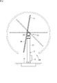
- FIG. 6A is a side view showing an example of the sun tracking attitude of the array 1.
- the attitude control of the array 1 is performed so that the light receiving surface 1a faces the sun, and the attitude of the array 1 becomes the sun tracking attitude.
- the array 1 since the sun altitude is 0 ° at sunrise or sunset, the array 1 takes a vertical posture in which the light receiving surface 1a is parallel to the vertical direction. In the daytime when the sun altitude exceeds 0 °, the array 1 takes a posture in which the light receiving surface faces upward.
- the incident angle of sunlight on the light receiving surface 1a becomes 0 °, and efficient power generation is performed.
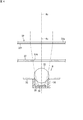
- FIG. 6B is a side view showing an example of the retracted posture of the array 1.
- the driving device 6 executes a retreat operation for changing the attitude of the array 1 to the retreat attitude.
- the retracted posture is a horizontal posture in which the light receiving surface 1a of the array 1 faces vertically downward.
- the retracting posture may not be a horizontal posture as long as the light receiving surface faces downward, and may be, for example, a posture inclined at an angle of 45 ° or less with respect to a horizontal plane.
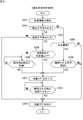
- FIG. 7 is a flowchart illustrating an example of the attitude control process of the array 1.
- the CPU 51 determines whether or not it is during the day (step S101). In this process, for example, the CPU 51 determines whether it is daytime or nighttime based on time information obtained by a clock function provided in the control unit 5, or determines whether it is daytime or nighttime based on the solar radiation intensity detected by the solar radiation sensor 702. Or you can.
- the CPU 51 determines whether or not the array 1 is in the evacuation posture (step S102). When the array 1 is in the retracted posture (YES in step S102), the CPU 51 ends the posture control processing. On the other hand, when the array 1 is not in the retracting posture (NO in step S102), the CPU 51 causes the driving device 6 to execute the retracting operation (step S103). Thereby, the attitude of the array 1 changes to the retracted attitude. After the processing in step S103, the CPU 51 ends the attitude control processing. With the above-described processing, the array 1 assumes the retracted posture at night.
- step S101 determines whether the evacuation flag is set (that is, set to ON) (step S104). If the save flag is down (that is, set to off) (NO in step S104), CPU 51 causes drive device 6 to execute a sun tracking operation (step S105).
- the array 1 takes a posture facing the sun, and the incident angle of the sunlight on the light receiving surface 1a becomes 0 ° (see FIG. 4). As a result, the light converged by the condenser lens 32f is guided to the cell 38, and power is generated.
- the CPU 51 ends the attitude control process.
- step S104 If the evacuation flag is set (YES in step S104), the CPU 51 shifts the processing to step S102.
- the posture control process is terminated, and when the array 1 is not in the retreating posture (NO in step S102), the retreat operation is executed.
- Step S103 That is, when the evacuation flag is set, the array 1 takes the evacuation posture. After the execution of the evacuation operation, the CPU 51 ends the attitude control process.
- the CPU 51 repeatedly executes the posture control process as described above at predetermined time intervals (for example, at one second intervals).
- the array 1 can take an appropriate posture according to the situation.
- FIG. 8 is a flowchart illustrating an example of the precipitation state determination process.
- the CPU 51 executes the following precipitation condition determination processing in time parallel with the attitude control processing.
- the CPU 51 receives the weather information from the external data source 9 (Step S201).
- the weather information includes information on predicted precipitation intensity and predicted precipitation time.
- the CPU 51 determines whether or not precipitation is predicted based on weather information (step S202). In the process of step S202, for example, the CPU 51 determines that precipitation is predicted if the predicted rainfall intensity included in the weather information exceeds 0 mm / h, and does not predict the rainfall if the predicted rainfall intensity is 0 mm / h. Can be determined.
- step S203 the CPU 51 determines whether light rain is predicted based on weather information.
- the CPU 51 determines that light rain is predicted when the predicted rainfall intensity is 1 mm / h or less, for example, and does not predict light rainfall when the predicted rainfall intensity exceeds 1 mm / h.
- heavy rain is predicted.
- “light rain” means rain having a rainfall intensity equal to or lower than a predetermined value
- “heavy rain” means rain having a higher rainfall intensity than light rain, that is, rain having a rainfall intensity higher than a predetermined value. means.
- the light rain is rain having a precipitation intensity of 1 mm / h or less
- rain having a precipitation intensity higher than 1 mm / h is heavy rain.
- Predicting light rain is an example of light rain conditions according to the present embodiment. That is, when light rain is predicted (YES in step S203), the light rain condition is satisfied.
- the light rain condition can be a condition based on at least one of precipitation intensity, precipitation, and cloudiness.
- step S204 determines whether the solar radiation intensity detected by the solar radiation sensor 702 is equal to or less than a predetermined value. If the solar irradiance is high, it can be estimated that there are few clouds and it takes time until precipitation. On the other hand, if the solar radiation intensity is low, it can be estimated that there are many clouds and precipitation is near. Therefore, when the solar radiation intensity is equal to or less than the predetermined value (YES in step S204), CPU 51 sets a save flag (step S205). As a result, the operation is switched from the sun tracking operation to the evacuation operation, and the attitude of the array 1 is changed to the evacuation attitude.
- CPU 51 determines whether or not the time reaches a time set before the predicted rain time (hereinafter, referred to as “precipitation approach time”) (step S206). . It takes a certain time for the array 1 to transition from the sun tracking posture to the evacuation posture. For this reason, if the evacuation operation is started after the predicted rainfall time has been reached, it will start to rain until the posture change to the evacuation posture is completed, and water droplets may adhere to the light receiving surface 1a. Therefore, in this example, the evacuation operation is started at the timing when the precipitation approach time is reached.
- the attitude of the array 1 can be set to the attitude that can cope with the light rain, such as the evacuation attitude. Therefore, if the CPU 51 has not reached the precipitation approach time (NO in step S206), the CPU 51 returns the process to step S206, and if it has reached the precipitation approach time (YES in step S206), sets the evacuation flag (step S205). .
- the set time can be determined based on the maximum time required for the retreat operation, that is, the time required for the array 1 to transition from the horizontal position in which the light receiving surface 1a faces upward to the retreat position. .
- the evacuation flag is set, and the operation switches from the sun tracking operation to the evacuation operation.
- the attitude of the array 1 shifts from the sun tracking attitude to the retracted attitude.
- the sun tracking operation can be performed to generate power efficiently.
- step S207 determines whether or not the observed rain is no longer a light rain.
- An example of a condition for determining that the rain has stopped may be that the intensity of the rainfall is equal to or less than the measurement limit of the precipitation sensor 703 for a predetermined time (for example, two minutes).
- a condition for determining that heavy rain has occurred may be that the rainfall intensity is higher than 1 mm / h for a predetermined time (for example, two minutes).
- step S207 If light rain is continuously observed (NO in step S207), CPU 51 executes step S207 again. On the other hand, when it is no longer light rain (YES in step S207), CPU 51 turns down the evacuation flag (step S208). Thereby, the retreat operation is released, and the sun tracking operation is performed. As a result, the attitude of the array 1 shifts to the sun tracking attitude. If the attitude of the array 1 becomes the sun tracking attitude when the weather recovers, power generation starts. If the attitude of the array 1 becomes the sun tracking attitude when heavy rain occurs, dirt on the light receiving surface 1a is washed away by rain. When the evacuation flag is defeated, the CPU 51 ends the precipitation condition determination process.
- step S203 If the light rain is not predicted in step S203, that is, if the heavy rain is predicted (NO in step S203), the CPU 51 shifts the processing to step S208 and turns off the evacuation flag.
- Predicting heavy rain is an example of heavy rain conditions according to the present embodiment. That is, when heavy rain is predicted, the heavy rain condition is satisfied.
- the value of the amount of precipitation per hour that divides light rain from heavy rain may be defined, and the prediction of precipitation exceeding this value may be set as the heavy rain condition.
- a value of the amount of cloud per hour that separates light rain from heavy rain may be defined, and a cloud amount exceeding this value may be predicted as the heavy rain condition.
- a complex condition combining at least two of the above-mentioned heavy rain conditions of precipitation intensity, precipitation, and cloudiness may be set as the heavy rain condition.
- step S203 When heavy rain is predicted (YES in step S203), the evacuation flag is defeated, so that the evacuation operation is avoided, and the attitude of the array 1 becomes the sun tracking attitude. Thereby, the dirt on the light receiving surface 1a can be washed away with rain.
- the evacuation flag is defeated, the CPU 51 ends the precipitation condition determination process.
- step S202 determines whether rain has been observed based on the output signal of precipitation sensor 703 (step S209). In the process of step S209, the CPU 51 determines that rain has been observed if rain has been measured, regardless of, for example, the value measured by the precipitation sensor 703. If the rainfall intensity is equal to or less than the measurement limit of the precipitation sensor 703, rain is observed. It can be determined that it is not performed.
- step S209 If no rain is observed (NO in step S209), CPU 51 shifts the processing to step S208 and turns off the evacuation flag. Thus, when it is not raining, the array 1 takes the sun tracking attitude, and power is generated. After the evacuation flag is defeated, the CPU 51 ends the precipitation condition determination process.
- step S210 determines whether or not the observed rain is light rain (step S210). That is, in the process of step S210, it is determined whether the precipitation intensity detected by the precipitation sensor 703 is equal to or less than a predetermined value, for example, 1 mm / h. If the precipitation intensity is equal to or less than the predetermined value, the observed rain is determined to be light rain, and if the precipitation intensity is higher than the predetermined value, the observed rain is determined to be heavy rain.
- a predetermined value for example, 1 mm / h.
- the CPU 51 shifts the processing to step S205 and sets a save flag. As a result, a retreat operation is performed.
- the CPU 51 executes the processing of steps S207 and S208, and ends the precipitation state determination processing.
- the CPU 51 shifts the processing to step S208 and turns off the evacuation flag.
- the fact that the observed rain is heavy rain is an example of the heavy rain condition according to the present embodiment. That is, when heavy rain is observed, the heavy rain condition is satisfied.
- the evacuation flag is defeated, the evacuation operation is not performed, and the attitude of the array 1 becomes the sun tracking attitude. Thereby, the dirt on the light receiving surface 1a can be washed away with rain.
- the CPU 51 ends the precipitation condition determination process.
- FIG. 9 is a graph illustrating an example of a change in the power generation performance of the photovoltaic power generation panel before and after light rain.
- the vertical axis indicates the power generation performance, and the power generation performance is compared by normalizing the ratio of the actual output (kW) to the rated output (kW) measured within a predetermined time during the day by the amount of solar radiation. Value.
- the power generation performance is approximately 85%.
- the power generation performance is reduced to approximately 70% due to the contamination on the light receiving surface 1a.
- dirt was removed from the light receiving surface 1a, so that the power generation performance was restored to the same level as before the precipitation. As shown in this example, when dirt adheres to the light receiving surface 1a due to light rain, the power generation performance rapidly decreases.
- FIG. 10 is a graph illustrating an example of a change in the power generation performance of the solar power generation panel before and after heavy rain.
- the vertical axis indicates the power generation performance.
- the example shown in FIG. 10 is a change in power generation performance when a rainfall with a precipitation intensity of about 60 mm / h falls.
- the power generation performance before the precipitation was about 84%
- the power generation performance after the precipitation was about 88%. Therefore, as a result of the dirt on the light receiving surface 1a being washed away by the heavy rain, the power generation performance was increased by about 4%.
- the following table shows the evaluation results.
- the total of each of the direct solar radiation amount, the measured power generation amount, and the estimated power generation amount for one day to be evaluated is shown.
- the loss of power generation due to the evacuation operation is obtained as (actually measured power generation-estimated power generation), and is 13.3 kWh / day.
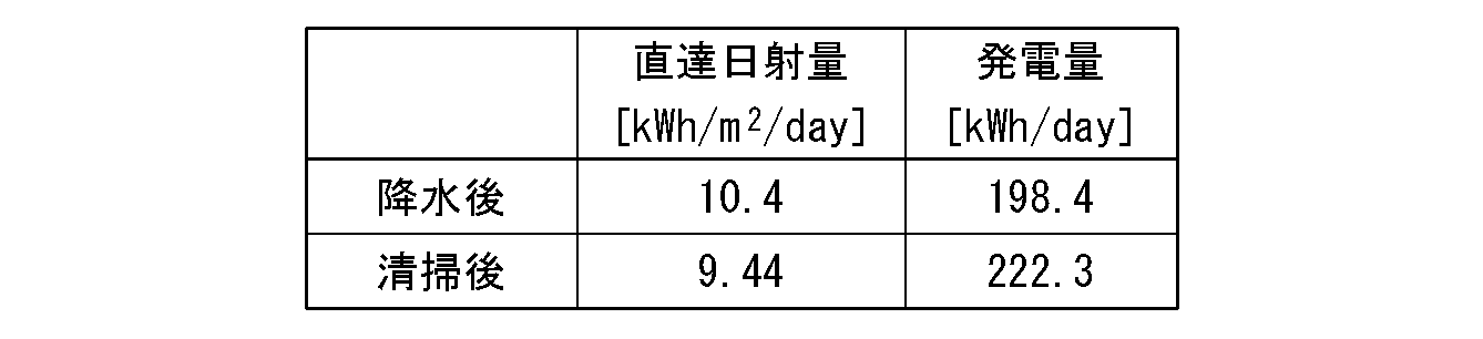
- the following table shows the amount of power generation immediately after the light receiving surface 1a is contaminated by precipitation and when the power generation performance is restored by cleaning the light receiving surface 1a.
- “after precipitation” indicates immediately after the light receiving surface 1a is stained
- “after cleaning” indicates immediately after the light receiving surface 1a is cleaned.
- both the case where the rainfall of a predetermined or less rainfall is predicted by an external organization and the case where the light rain is observed by the precipitation sensor 703 provided in the photovoltaic power generator 100 are both low.
- the present invention is not limited to this.
- the precipitation sensor 703 only monitors the precipitation. It can be determined whether the light rain condition has been satisfied. In the case where the precipitation sensor 703 is not provided or the like, it can be determined whether or not the light rain condition has been satisfied only by the weather information provided from the external data source 9.
Landscapes
- Physics & Mathematics (AREA)
- General Physics & Mathematics (AREA)
- Engineering & Computer Science (AREA)
- Automation & Control Theory (AREA)
- Life Sciences & Earth Sciences (AREA)
- Sustainable Development (AREA)
- Photovoltaic Devices (AREA)
Abstract
太陽光発電装置は、受光面を有する太陽光発電パネルと、前記太陽光発電パネルの姿勢を変化させる駆動装置と、日中において所定の弱雨条件が成立する場合に、前記太陽光発電パネルの姿勢を、前記太陽光発電パネルの受光面が下向きとなる待避姿勢へと変化させる待避動作を前記駆動装置に実行させる制御部と、を備える。
Description
この発明は太陽光発電装置及び太陽光発電装置の制御方法に関する。
太陽光発電装置では、発電効率を高めるために、太陽光発電パネルにおける受光強度をできるだけ高くすることが重要である。そのため、太陽光発電パネルの姿勢を変化させ、受光面を自動的に太陽に追尾させる太陽追尾機能を備えた太陽光発電装置がある。かかる太陽光発電装置は、日射が得られない夜間には太陽追尾を実行しない。
ところで、野外に設置される太陽光発電装置では、自然環境にさらされるため受光面に汚れが付着する。受光面に汚れが付着すると、太陽光発電パネルにおける受光強度が下がり、発電効率が低下する。そこで、特許文献1には、夜間などの十分な発電性能が見込めない状況において、太陽光発電パネルの受光面を、雨を受けやすい斜め上向きにし、塵埃等の付着物を雨で洗い流す太陽光発電装置が提案されている。
本開示の一態様に係る太陽光発電装置は、受光面を有する太陽光発電パネルと、前記太陽光発電パネルの姿勢を変化させる駆動装置と、日中において所定の弱雨条件が成立する場合に、前記太陽光発電パネルの姿勢を、前記太陽光発電パネルの受光面が下向きとなる待避姿勢へと変化させる待避動作を前記駆動装置に実行させる制御部と、を備える。
また、本開示の一の態様に係る太陽光発電装置の制御方法は、太陽光発電パネルの姿勢を変化させる駆動装置に、前記太陽光発電パネルの姿勢を、前記太陽光発電パネルの受光面を太陽に向ける受光姿勢とさせ、日中において所定の弱雨条件が成立する場合に、前記太陽光発電パネルの姿勢を、前記受光姿勢から、前記受光面が下向きとなる待避姿勢へと変化させる待避動作を前記駆動装置に実行させる。
本開示は、このような特徴的な制御部を備える太陽光発電装置、及びかかる特徴的な処理をステップとする太陽光発電装置の制御方法として実現することができるだけでなく、かかるステップをコンピュータに実行させるためのプログラムとして実現することができる。また、かかるステップの一部又は全部を実行する機能を有する半導体集積回路として実現したり、太陽光発電装置を含む太陽光発電システムとして実現したりすることができる。
<本開示が解決しようとする課題>
強い雨の場合は、太陽光発電パネルの受光面を洗い流すのに十分な水量が見込めるが、弱い雨の場合は、受光面を雨水が流れず、大量の水滴が受光面に付着したままとなることがある。受光面に付着した水滴が乾燥すると、雨の含有物が汚れとして残留する。つまり、弱い雨の場合には、クリーニング効果が期待できず、かえって受光面を汚す可能性がある。
強い雨の場合は、太陽光発電パネルの受光面を洗い流すのに十分な水量が見込めるが、弱い雨の場合は、受光面を雨水が流れず、大量の水滴が受光面に付着したままとなることがある。受光面に付着した水滴が乾燥すると、雨の含有物が汚れとして残留する。つまり、弱い雨の場合には、クリーニング効果が期待できず、かえって受光面を汚す可能性がある。
<本開示の効果>
本開示によれば、弱い雨が降る場合に、太陽光発電パネルの受光面への汚れの付着を防止することができる。
本開示によれば、弱い雨が降る場合に、太陽光発電パネルの受光面への汚れの付着を防止することができる。
<本発明の実施形態の概要>
以下、本発明の実施形態の概要を列記して説明する。
(1) 本実施形態に係る太陽光発電装置は、受光面を有する太陽光発電パネルと、前記太陽光発電パネルの姿勢を変化させる駆動装置と、日中において所定の弱雨条件が成立する場合に、前記太陽光発電パネルの姿勢を、前記太陽光発電パネルの受光面が下向きとなる待避姿勢へと変化させる待避動作を前記駆動装置に実行させる制御部と、を備える。これにより、弱い雨による受光面への汚れの付着を防止することができ、汚れの付着による発電効率の低下を抑制することができる。なお、太陽光発電パネルは、集光型の太陽光発電パネルでもよく、結晶シリコン型の太陽光発電パネルでもよい。また、待避姿勢は、受光面が下向きとなる姿勢であれば、水平姿勢でもよく、傾斜姿勢でもよい。ただし、受光面に雨が当たることを防止するため、例えば水平面に対して45°以下の傾斜角度とすることが好ましい。
以下、本発明の実施形態の概要を列記して説明する。
(1) 本実施形態に係る太陽光発電装置は、受光面を有する太陽光発電パネルと、前記太陽光発電パネルの姿勢を変化させる駆動装置と、日中において所定の弱雨条件が成立する場合に、前記太陽光発電パネルの姿勢を、前記太陽光発電パネルの受光面が下向きとなる待避姿勢へと変化させる待避動作を前記駆動装置に実行させる制御部と、を備える。これにより、弱い雨による受光面への汚れの付着を防止することができ、汚れの付着による発電効率の低下を抑制することができる。なお、太陽光発電パネルは、集光型の太陽光発電パネルでもよく、結晶シリコン型の太陽光発電パネルでもよい。また、待避姿勢は、受光面が下向きとなる姿勢であれば、水平姿勢でもよく、傾斜姿勢でもよい。ただし、受光面に雨が当たることを防止するため、例えば水平面に対して45°以下の傾斜角度とすることが好ましい。
(2) また、本実施形態に係る太陽光発電装置において、前記弱雨条件は、降水強度、降水量、及び雲量のうちの少なくとも1つに基づく条件であってもよい。これにより、降水強度、降水量、及び雲量のうちの少なくとも1つに基づいて弱雨と判断される場合に、太陽光発電パネルが待避姿勢をとり、受光面への汚れの付着を防止することができる。
(3) また、本実施形態に係る太陽光発電装置において、前記弱雨条件は、弱雨が予測される条件であり、前記制御部は、前記弱雨が予測される時刻の所定時間前に、前記待避動作を前記駆動装置に開始させてもよい。これにより、弱雨が降り始めるより所定時間前に待避動作が開始されるので、弱雨が降り始める時点では太陽光発電パネルの姿勢を待避姿勢等の弱雨に対処できる姿勢とすることができる。
(4) また、本実施形態に係る太陽光発電装置において、前記制御部は、日中において前記弱雨条件とは異なる強雨条件が成立する場合に、前記待避動作を前記駆動装置に回避させてもよい。これにより、一定の強い雨が降る場合に、受光面に付着した汚れを洗い流すことができる。
(5) また、本実施形態に係る太陽光発電装置において、前記制御部は、日中において前記太陽光発電パネルが前記待避姿勢をとっており、且つ、前記弱雨条件が成立しない場合に、前記待避姿勢を解除する解除動作を前記駆動装置に実行させてもよい。これにより、雨がやんだ場合、又は一定の強い雨に変化した場合に、太陽光発電パネルの待避姿勢を解除して、太陽光発電パネルの姿勢を、太陽光を受光面で受光する受光姿勢、雨で受光面の汚れを洗い流す洗浄姿勢等に変化させることができる。
(6) また、本実施形態に係る太陽光発電装置において、前記駆動装置は、前記太陽光発電パネルが太陽を追尾する太陽追尾動作を実行可能であり、前記制御部は、前記太陽追尾動作を実行している前記駆動装置に前記待避動作を実行させる場合、前記駆動装置に前記太陽追尾動作から前記待避動作へ切り替えさせてもよい。これにより、太陽光発電装置が、晴天では太陽追尾動作を実行して高効率に発電を行い、弱雨条件が成立する場合には、太陽追尾動作から待避動作へ切り替えて受光面への汚れの付着を防止することができる。
(7) また、本実施形態に係る太陽光発電装置の制御方法は、太陽光発電パネルの姿勢を変化させる駆動装置に、前記太陽光発電パネルの姿勢を、前記太陽光発電パネルの受光面を太陽に向ける受光姿勢とさせ、日中において所定の弱雨条件が成立する場合に、前記太陽光発電パネルの姿勢を、前記受光姿勢から、前記受光面が下向きとなる待避姿勢へと変化させる待避動作を前記駆動装置に実行させる。これにより、弱い雨による受光面への汚れの付着を防止することができ、汚れの付着による発電効率の低下を抑制することができる。
<本発明の実施形態の詳細>
以下、図面を参照しつつ、本発明の実施形態の詳細を説明する。なお、以下に記載する実施形態の少なくとも一部を任意に組み合わせてもよい。
以下、図面を参照しつつ、本発明の実施形態の詳細を説明する。なお、以下に記載する実施形態の少なくとも一部を任意に組み合わせてもよい。
〔太陽光発電装置の構成〕
以下、本実施形態に係る太陽光発電装置の構成について説明する。
以下、本実施形態に係る太陽光発電装置の構成について説明する。
《太陽光発電装置の全体構成》
図1は、本実施形態に係る太陽光発電装置の構成を示す斜視図であり、図2は、その側面図である。太陽光発電装置100は、上部側で連続し、下部側で左右に分かれた形状のアレイ1と、その支持装置2とを備える。アレイ1は、実施形態に係る太陽光発電パネルの一例である。かかるアレイ1は、背面側の架台11(図2)上に集光型太陽光発電モジュール1Mを整列させて構成されている。図1の例では、左右のウイングを構成する192(96(=12×8)×2)個と、中央の渡り部分の8個との、合計200個のモジュール1Mの集合体として、アレイ1が構成されている。
図1は、本実施形態に係る太陽光発電装置の構成を示す斜視図であり、図2は、その側面図である。太陽光発電装置100は、上部側で連続し、下部側で左右に分かれた形状のアレイ1と、その支持装置2とを備える。アレイ1は、実施形態に係る太陽光発電パネルの一例である。かかるアレイ1は、背面側の架台11(図2)上に集光型太陽光発電モジュール1Mを整列させて構成されている。図1の例では、左右のウイングを構成する192(96(=12×8)×2)個と、中央の渡り部分の8個との、合計200個のモジュール1Mの集合体として、アレイ1が構成されている。
支持装置2は、支柱21と、基礎22と、2軸駆動部23と、駆動軸となる水平軸24(図2)とを備えている。支柱21は、下端が基礎22に固定され、上端に2軸駆動部23を備えている。支柱21の下端近傍には、電気接続及び電気回路収納のためのボックス13(図2)が設けられている。
図2において、基礎22は、上面のみが見える程度に地中に堅固に埋設される。基礎22を地中に埋設した状態で、支柱21は鉛直となり、水平軸24は水平となる。2軸駆動部23は、水平軸24を、方位角(支柱21を中心軸とした角度)及び仰角(水平軸24を中心軸とした角度)の2方向に回動させることができる。水平軸24は、架台11に固定されている。従って、水平軸24が方位角又は仰角の方向に回動すれば、アレイ1もその方向に回動する。
なお、図1,図2では1本の支柱21でアレイ1を支える支持装置2を示したが、支持装置2の構成は、これに限られるものではない。要するに、アレイ1を、2軸(方位角、仰角)で可動なように支持できる支持装置であればよい。
《モジュールの構成例》
図3は、モジュール1Mの構成の一例を示す斜視図である。本例では、モジュール1Mを集光型の太陽光発電モジュールとしている。図において、モジュール1Mは、例えば金属製で長方形の平底容器状の筐体31と、その上に蓋のように取り付けられる集光部32と、を備えている。集光部32は、例えば1枚の透明なガラス板32aの裏面に樹脂製の集光レンズ32fが貼り付けられて構成されている。例えば図示の正方形(10個×14個)の区画の1つ1つが、集光レンズ32fとしてのフレネルレンズであり、太陽光を焦点位置に収束させることができる。
図3は、モジュール1Mの構成の一例を示す斜視図である。本例では、モジュール1Mを集光型の太陽光発電モジュールとしている。図において、モジュール1Mは、例えば金属製で長方形の平底容器状の筐体31と、その上に蓋のように取り付けられる集光部32と、を備えている。集光部32は、例えば1枚の透明なガラス板32aの裏面に樹脂製の集光レンズ32fが貼り付けられて構成されている。例えば図示の正方形(10個×14個)の区画の1つ1つが、集光レンズ32fとしてのフレネルレンズであり、太陽光を焦点位置に収束させることができる。
筐体31の底面31b上には、フレキシブルプリント配線板33が配置されている。フレキシブルプリント配線板33上の所定位置にはセル(発電素子)を保持するセルパッケージ34が搭載されている。図中の、二点鎖線の「○」で囲んでいる部位は、受光部Rの拡大図である。受光部Rにおいて、セルパッケージ34上には2次レンズ35があり、二次レンズ35の周りには保護板36がある。2次レンズ35は例えばボールレンズである。保護板36は、例えば、円環状の金属体であり、市販のワッシャを用いることができる。保護板36は2次レンズ15から太陽光の収束光が外れた場合に、収束光がセル周辺に熱的なダメージを与えることを防止している。また、保護板36は、収束光が全て2次レンズ35に入っている場合であっても、筐体31内での散乱光を受けてこれを反射する。
受光部Rは、集光レンズ32fの各々に対応して同数、同一間隔で、設けられている。受光部Rと集光部32との間には、遮蔽板37が設けられている。遮蔽板37には、個々の集光レンズ32fに対応した位置に、1つの集光レンズ32fの外形状と相似な正方形の開口37aが形成されている。集光レンズ32fによって収束する光は、開口37aを通過する。太陽光の入射方向と受光部Rの光軸とが大きくずれた場合には、ずれた位置に集光しようとする光は遮蔽板37に当たるようになっている。
図4は、光学系の最小の基本構成を現す断面図の一例である。図4では、太陽光の入射方向が集光部32の集光レンズ32fに対して垂直であり、入射方向ASと光軸AXとが互いに平行である(つまり、入射方向ASと光軸AXとが合致している)。このとき、集光レンズ32fによって収束させられた光は、遮蔽板37の開口37aを通り抜け、2次レンズ35に入射する。2次レンズ35は、入射した光をセル38に導く。セル38は、セルパッケージ34の中に保持されている。保護板36は、セルパッケージ34の上端に乗るように取り付けられている。2次レンズ35とセル38との間には、光透過性の樹脂39が封入されている。図4に示されるように、集光レンズ32fとセル38とを結ぶ光軸AXが太陽光の入射方向ASに合致しているとき、集光レンズ32fによって集められた光の全てがセル38に導かれる。セル38は、受けた光の大部分を電気エネルギーに変換して電力を出力する。
《太陽光発電装置100の制御部の構成例》
図5は、太陽光発電装置100の制御部の概要の一例を示すブロック図である。制御部5は、例えばボックス13(図2参照)内に設けられている。制御部5は、CPU51及びメモリ52を備えている。メモリ52には、後述する姿勢制御処理、及び降水状態判定処理を実行するための制御プログラム52aが格納されており、CPU51は、メモリ52に格納された制御プログラム52aを実行することができる。また、例えばボックス13内には、方位角駆動用のモータ23aと、仰角駆動用のモータ23eとのそれぞれを駆動する駆動装置6が設けられており、CPU51は制御プログラム52aを実行することにより駆動装置6に制御信号を出力し、モータ23a,23eのそれぞれを制御することができる。これにより、CPU51は、方位角駆動用のモータ23aと、仰角駆動用のモータ23eとを駆動して、アレイ1が太陽に正対するように、駆動装置6に太陽追尾動作を行わせる。また、CPU51は、後述するように、弱雨条件が成立する場合に、アレイ1の姿勢を待避姿勢に変化させる待避動作を行わせる。メモリ52には、待避動作の実行可否を示す待避フラグが設けられている(図示せず)。
図5は、太陽光発電装置100の制御部の概要の一例を示すブロック図である。制御部5は、例えばボックス13(図2参照)内に設けられている。制御部5は、CPU51及びメモリ52を備えている。メモリ52には、後述する姿勢制御処理、及び降水状態判定処理を実行するための制御プログラム52aが格納されており、CPU51は、メモリ52に格納された制御プログラム52aを実行することができる。また、例えばボックス13内には、方位角駆動用のモータ23aと、仰角駆動用のモータ23eとのそれぞれを駆動する駆動装置6が設けられており、CPU51は制御プログラム52aを実行することにより駆動装置6に制御信号を出力し、モータ23a,23eのそれぞれを制御することができる。これにより、CPU51は、方位角駆動用のモータ23aと、仰角駆動用のモータ23eとを駆動して、アレイ1が太陽に正対するように、駆動装置6に太陽追尾動作を行わせる。また、CPU51は、後述するように、弱雨条件が成立する場合に、アレイ1の姿勢を待避姿勢に変化させる待避動作を行わせる。メモリ52には、待避動作の実行可否を示す待避フラグが設けられている(図示せず)。
太陽光発電装置100は、追尾センサ701、日射センサ702、及び降水センサ703を備える。追尾センサ701、日射センサ702、及び降水センサ703は、アレイ1の空きスペース、又はアレイ1の近傍に設置される。降水センサ703は、例えば降水粒径測定器又は降水強度計であり、降水強度に関する情報を出力する。制御部5にはA/Dコンバータ53が設けられており、CPU51には、A/Dコンバータ53が接続されている。追尾センサ701、日射センサ702、及び降水センサ703のそれぞれはA/Dコンバータ53に接続され、追尾センサ701、日射センサ702、及び降水センサ703のそれぞれの出力信号は、A/Dコンバータ53によってデジタル信号に変換されて制御部5に入力される。また、アレイ1の発電電力は、電力センサ704で検知することができ、電力センサ704はA/Dコンバータ53に接続される。これにより、CPU51には電力センサ704によって検知された電力を示す信号が入力される。制御部5は、太陽光発電装置100の設置場所の緯度、経度を記憶し、また、時計機能を有している。制御部5は、追尾センサ701の出力信号と、緯度・経度・時刻から演算される太陽の位置とに基づいて、太陽光発電パネル1が常に太陽に向くよう、駆動装置6に太陽追尾動作を実行させる。但し、追尾センサ701は設けない場合もある。その場合には、緯度・経度・時刻から演算される太陽の位置にのみ基づいて太陽追尾動作が行われる。
また、制御部5は外部データソース9に例えばインターネットを介して接続されている。外部データソース9は、気象情報を提供する、例えば国・地方公共団体の機関又は民間気象情報会社が運営するサーバである。かかる外部データソース9は、太陽光発電装置100が設置されている場所における局所的な気象情報を制御部5に提供する。
〔太陽光発電装置の動作〕
次に、本実施形態に係る太陽光発電装置の動作について説明する。
次に、本実施形態に係る太陽光発電装置の動作について説明する。
《太陽光発電パネルの姿勢》
アレイ1の左右のウイングの間には空間が設けられている(図1参照)。アレイ1が仰角方向に回動すると支柱21がこの空間内に位置し、支柱21とアレイ1との接触が防止される。このように、アレイ1は支柱21と干渉することなく、受光面を上方に向けた水平姿勢から、受光面を下方に向けた水平姿勢まで、任意の姿勢をとることができる(図2参照)。太陽光発電装置100では、制御部5による姿勢制御により、アレイ1の姿勢を、受光面を太陽に正対させる太陽追尾姿勢と、受光面を下方に向ける待避姿勢との間で変化させることができる。
アレイ1の左右のウイングの間には空間が設けられている(図1参照)。アレイ1が仰角方向に回動すると支柱21がこの空間内に位置し、支柱21とアレイ1との接触が防止される。このように、アレイ1は支柱21と干渉することなく、受光面を上方に向けた水平姿勢から、受光面を下方に向けた水平姿勢まで、任意の姿勢をとることができる(図2参照)。太陽光発電装置100では、制御部5による姿勢制御により、アレイ1の姿勢を、受光面を太陽に正対させる太陽追尾姿勢と、受光面を下方に向ける待避姿勢との間で変化させることができる。
図6Aは、アレイ1の太陽追尾姿勢の一例を示す側面図である。駆動装置6が太陽追尾動作を実行すると、受光面1aが太陽に正対するようにアレイ1の姿勢制御が行われ、アレイ1の姿勢が太陽追尾姿勢となる。例えば、日の出又は日の入りにおいては太陽高度が0°であるため、アレイ1は受光面1aが鉛直方向と平行になる鉛直姿勢をとる。また、太陽高度が0°を超える日中においては、アレイ1は受光面が上方を向く姿勢をとる。アレイ1が太陽追尾姿勢をとることにより、受光面1aに対する太陽光の入射角が0°となり、効率的な発電が行われる
図6Bは、アレイ1の待避姿勢の一例を示す側面図である。太陽追尾動作の実行中に一定の弱雨条件が成立すると、駆動装置6がアレイ1の姿勢を待避姿勢へと変化させる待避動作を実行する。図6Bに示される例では、待避姿勢はアレイ1の受光面1aが鉛直下方を向く水平姿勢とされる。なお、待避姿勢は受光面が下方を向く姿勢であれば水平姿勢でなくてもよく、例えば水平面に対して45°以下の角度で傾斜した姿勢であってもよい。
《太陽光発電装置100の動作例》
図7は、アレイ1の姿勢制御処理の一例を示すフローチャートである。CPU51は、日中であるか否かを判定する(ステップS101)。この処理では、CPU51が、例えば、制御部5が備える時計機能によって得られる時刻情報により日中か夜間かを判定したり、日射センサ702によって検出される日射強度により日中か夜間かを判定したりすることができる。
図7は、アレイ1の姿勢制御処理の一例を示すフローチャートである。CPU51は、日中であるか否かを判定する(ステップS101)。この処理では、CPU51が、例えば、制御部5が備える時計機能によって得られる時刻情報により日中か夜間かを判定したり、日射センサ702によって検出される日射強度により日中か夜間かを判定したりすることができる。
日中ではないと判定された場合(ステップS101においてNO)、CPU51は、アレイ1が待避姿勢をとっているか否かを判定する(ステップS102)。アレイ1が待避姿勢をとっている場合(ステップS102においてYES)、CPU51は姿勢制御処理を終了する。他方、アレイ1が待避姿勢をとっていない場合(ステップS102においてNO)、CPU51は駆動装置6に待避動作を実行させる(ステップS103)。これにより、アレイ1の姿勢が待避姿勢へと変化する。ステップS103の処理の後、CPU51は姿勢制御処理を終了する。以上のような処理により、夜間ではアレイ1が待避姿勢をとることになる。
日中であると判定された場合(ステップS101においてYES)、CPU51は、待避フラグが立っているか(つまり、オンにセットされているか)否かを判定する(ステップS104)。待避フラグが倒れている(つまり、オフにセットされている)場合(ステップS104においてNO)、CPU51は、駆動装置6に太陽追尾動作を実行させる(ステップS105)。この太陽追尾動作により、アレイ1が太陽に正対する姿勢をとり、受光面1aに対する太陽光の入射角度が0°となる(図4参照)。この結果、集光レンズ32fによる収束光がセル38に導かれ、発電が行われる。太陽追尾動作を実行した後、CPU51は姿勢制御処理を終了する。
待避フラグが立っている場合(ステップS104においてYES)、CPU51は、ステップS102へ処理を移す。これにより、アレイ1が待避姿勢をとっている場合(ステップS102においてYES)、姿勢制御処理が終了され、アレイ1が待避姿勢をとっていない場合(ステップS102においてNO)、待避動作が実行される(ステップS103)。つまり、待避フラグが立っている場合、アレイ1が待避姿勢をとることになる。待避動作の実行後、CPU51は姿勢制御処理を終了する。
CPU51は、上記のような姿勢制御処理を所定時間間隔(例えば、1秒間隔)で繰り返し実行する。これにより、状況に応じてアレイ1が適切な姿勢をとることができる。
図8は、降水状態判定処理の一例を示すフローチャートである。CPU51は、以下のような降水状態判定処理を、姿勢制御処理と時間的に並行して実行する。
CPU51は、外部データソース9から気象情報を受信する(ステップS201)。気象情報には、予測降水強度と、予測降水時刻の情報が含まれている。CPU51は、気象情報に基づいて降水が予測されるか否かを判定する(ステップS202)。ステップS202の処理では、CPU51が、例えば気象情報に含まれる予測降水強度が0mm/hを超える場合に降水が予測されると判定し、予測降水強度が0mm/hである場合に降水が予測されないと判定することができる。
降水が予測される場合(ステップS202においてYES)、CPU51は気象情報に基づいて弱雨が予測されるか否かを判定する(ステップS203)。ステップS203の処理では、CPU51が、例えば予測降水強度が1mm/h以下である場合に弱雨が予測されると判定し、予測降水強度が1mm/hを超える場合に弱雨が予測されない、つまり、強雨が予測されると判定することができる。なお、ここでいう「弱雨」は、所定値以下の降水強度の雨を意味し、「強雨」は、弱雨に比べて降水強度が高い雨、つまり所定値より降水強度が高い雨を意味する。例えば、弱雨が降水強度1mm/h以下の雨の場合、降水強度が1mm/hより高い雨が強雨となる。
弱雨が予測されることは、本実施形態に係る弱雨条件の一例である。つまり、弱雨が予測される場合(ステップS203においてYES)、弱雨条件が成立する。
例えば、弱雨と強雨とを区分する降水量の値を規定し、この値以下の降水量が予測されることを弱雨条件としてもよい。また、弱雨と強雨とを区分する雲量の値を規定し、この値以下の雲量が予測されることを弱雨条件としてもよい。また、上記の降水強度、降水量、及び雲量の弱雨条件の少なくとも2つを組み合わせた複合条件を弱雨条件としてもよい。換言すれば、弱雨条件は、降水強度、降水量、及び雲量のうちの少なくとも1つに基づく条件とすることができる。
弱雨が予測される場合(ステップS203においてYES)、CPU51は、日射センサ702によって検出される日射強度が所定値以下であるか否かを判定する(ステップS204)。日射強度が高ければ、雲が少なく、降水まで時間がかかると推定することができる。他方、日射強度が低ければ、雲が多く、降水が間近であると推定することができる。そこで、CPU51は、日射強度が所定値以下である場合(ステップS204においてYES)、待避フラグを立てる(ステップS205)。この結果、太陽追尾動作から待避動作に切り替わり、アレイ1の姿勢が待避姿勢へと変化する。
日射強度が所定値より高い場合(ステップS204においてNO)、CPU51は、予測降水時刻より設定時間前の時刻(以下、「降水接近時刻」という)に到達したか否かを判定する(ステップS206)。アレイ1が太陽追尾姿勢から待避姿勢へと移行する間には一定の時間を要する。このため、予測降水時刻に到達してから待避動作を開始すると、待避姿勢への姿勢変化を完了するまでに雨が降り始め、受光面1aに水滴が付着する可能性がある。したがって、この例では降水接近時刻に到達したタイミングで、待避動作を開始する。これにより、弱雨が降り始める時点ではアレイ1の姿勢を待避姿勢等の弱雨に対処できる姿勢とすることができる。そのため、CPU51は、降水接近時刻に到達していない場合(ステップS206においてNO)、ステップS206へ処理を戻し、降水接近時刻に到達した場合(ステップS206においてYES)、待避フラグを立てる(ステップS205)。なお、設定時間は、待避動作に必要な最大時間、つまり、アレイ1が、受光面1aが上方を向いた水平姿勢から、待避姿勢へと移行するのに必要な時間に基づいて決めることができる。
上記のように、弱雨条件が成立すると、待避フラグが立ち、太陽追尾動作から待避動作に切り替わる。これにより、アレイ1の姿勢が太陽追尾姿勢から待避姿勢へと移行する。晴天又は雲があっても降水がなく発電可能な日射強度が得られる気象状態では、太陽追尾動作を実行して高効率に発電を行うことができる。弱雨条件が成立し、アレイ1が待避姿勢をとると、受光面1aへの雨の付着が防止され、結果として受光面1aの汚れが防止される。
次にCPU51は、雨が降り始めた後、観測される雨が弱雨ではなくなったか否かを判定する(ステップS207)。ステップS207の処理では、雨が止んだ場合に弱雨ではなくなったと判定されてもよいし、雨が止んだ場合と、強雨となった場合とに、弱雨ではなくなったと判定されてもよい。雨が止んだと判定される条件の一例は、所定時間(例えば2分間)継続して降水強度が降水センサ703の測定限界以下となることとすることができる。また、強雨となったと判定される条件の一例は、所定時間(例えば2分間)継続して降水強度が1mm/hより高くなることとすることができる。
弱雨が継続して観測される場合(ステップS207においてNO)、CPU51はステップS207を再度実行する。他方、弱雨ではなくなった場合(ステップS207においてYES)、CPU51は待避フラグを倒す(ステップS208)。これにより、待避動作が解除され、太陽追尾動作が実行される。この結果、アレイ1の姿勢が太陽追尾姿勢へと移行する。天候が回復した場合にアレイ1の姿勢が太陽追尾姿勢となると、発電が始まる。また、強雨となった場合にアレイ1の姿勢が太陽追尾姿勢となると、受光面1aの汚れが雨で洗い流される。待避フラグを倒すと、CPU51は降水状態判定処理を終了する。
また、ステップS203において弱雨が予測されない場合、つまり、強雨が予測される場合には(ステップS203においてNO)、CPU51は、ステップS208へ処理を移し、待避フラグを倒す。強雨が予測されることは、本実施形態に係る強雨条件の一例である。つまり、強雨が予測される場合、強雨条件が成立する。
例えば、弱雨と強雨とを区分する1時間あたりの降水量の値を規定し、この値を超える降水量が予測されることを強雨条件としてもよい。また、弱雨と強雨とを区分する1時間あたりの雲量の値を規定し、この値を超える雲量が予測されることを強雨条件としてもよい。また、上記の降水強度、降水量、及び雲量の強雨条件の少なくとも2つを組み合わせた複合条件を強雨条件としてもよい。
強雨が予測される場合(ステップS203においてYES)、待避フラグが倒されることで、待避動作が回避され、アレイ1の姿勢が太陽追尾姿勢となる。これにより、受光面1aの汚れを雨で洗い流すことができる。待避フラグを倒すと、CPU51は降水状態判定処理を終了する。
また、ステップS202において降水が予測されない場合(ステップS202においてNO)、CPU51は、降水センサ703の出力信号に基づいて雨が観測されたか否かを判定する(ステップS209)。ステップS209の処理では、CPU51が、例えば降水センサ703による測定値を問わず、雨が測定されれば雨が観測されたと判定し、降水強度が降水センサ703の測定限界以下であれば雨が観測されないと判定することができる。
雨が観測されない場合には(ステップS209においてNO)、CPU51はステップS208へ処理を移し、待避フラグを倒す。これにより、雨が降っていない場合に、アレイ1が太陽追尾姿勢をとり、発電が行われる。待避フラグが倒された後、CPU51は降水状態判定処理を終了する。
他方、雨が観測された場合には(ステップS209においてYES)、CPU51は、観測された雨が弱雨であるか否かを判定する(ステップS210)。つまり、ステップS210の処理では、降水センサ703によって検出される降水強度が所定値、例えば1mm/h以下であるか否かが判定される。降水強度が所定値以下であれば、観測された雨が弱雨であると判定され、降水強度が所定値より高ければ、観測された雨が強雨であると判定される。観測された雨が弱雨であることは、本実施形態に係る弱雨条件の一例である。つまり、弱雨が観測される場合(ステップS210においてYES)、弱雨条件が成立する。この場合、CPU51は、ステップS205へ処理を移し、待避フラグを立てる。これにより、待避動作が実行される。アレイ1が待避姿勢をとると、受光面1aへの雨の付着が防止され、結果として受光面1aの汚れが防止される。待避フラグが立てられた後、CPU51はステップS207、S208の処理を実行し、降水状態判定処理を終了する。
観測された雨が弱雨ではない、即ち、強雨の場合には(ステップS210においてNO)、CPU51はステップS208へ処理を移し、待避フラグを倒す。観測された雨が強雨であることは、本実施形態に係る強雨条件の一例である。つまり、強雨が観測される場合、強雨条件が成立する。この場合、待避フラグが倒されることで、待避動作が実行されず、アレイ1の姿勢が太陽追尾姿勢となる。これにより、受光面1aの汚れを雨で洗い流すことができる。待避フラグが倒された後、CPU51は降水状態判定処理を終了する。
〔本実施形態に係る太陽光発電装置の制御方法の性能評価〕
発明者は、本実施形態に係る太陽光発電装置の制御方法の性能を評価した。以下、実施した評価について説明する。
発明者は、本実施形態に係る太陽光発電装置の制御方法の性能を評価した。以下、実施した評価について説明する。
《降水前後における発電性能の変化》
発明者は、アレイ1の受光面1aが弱雨で濡れた場合の性能の変化を調べた。図9は、弱雨の前後における太陽光発電パネルの発電性能の変化の一例を示すグラフである。図9において、縦軸は発電性能を示しており、この発電性能は、日中の所定時間内に計測された定格出力(kW)に対する実出力(kW)の割合を日射量で規格化して比較した値である。降水前の受光面1aが汚れていない状態では、約85%の発電性能を示しているが、降水後では、受光面1aの汚れによって約70%まで発電性能が落ちている。清掃後は受光面1aから汚れが取り除かれたため、降水前と同等の水準まで発電性能が回復している。この例に示されるように、弱雨によって受光面1aに汚れが付着すると、発電性能が急激に低下する。
発明者は、アレイ1の受光面1aが弱雨で濡れた場合の性能の変化を調べた。図9は、弱雨の前後における太陽光発電パネルの発電性能の変化の一例を示すグラフである。図9において、縦軸は発電性能を示しており、この発電性能は、日中の所定時間内に計測された定格出力(kW)に対する実出力(kW)の割合を日射量で規格化して比較した値である。降水前の受光面1aが汚れていない状態では、約85%の発電性能を示しているが、降水後では、受光面1aの汚れによって約70%まで発電性能が落ちている。清掃後は受光面1aから汚れが取り除かれたため、降水前と同等の水準まで発電性能が回復している。この例に示されるように、弱雨によって受光面1aに汚れが付着すると、発電性能が急激に低下する。
《強雨によるクリーニング効果》
強雨が降った場合にアレイ1に太陽追尾姿勢をとらせることで受光面1aの汚れが洗い流され、クリーニング効果が生じる。図10は、強雨の前後における太陽光発電パネルの発電性能の変化の一例を示すグラフである。図10において、縦軸は発電性能を示している。また、図10に示す例は、約60mm/hの降水強度の雨が降った場合の発電性能の変化である。図10に示されるように、降水前の発電性能は約84%であり、降水後の発電性能は約88%であった。したがって、強雨によって受光面1aの汚れが洗い流された結果、発電性能が約4%上昇した。
強雨が降った場合にアレイ1に太陽追尾姿勢をとらせることで受光面1aの汚れが洗い流され、クリーニング効果が生じる。図10は、強雨の前後における太陽光発電パネルの発電性能の変化の一例を示すグラフである。図10において、縦軸は発電性能を示している。また、図10に示す例は、約60mm/hの降水強度の雨が降った場合の発電性能の変化である。図10に示されるように、降水前の発電性能は約84%であり、降水後の発電性能は約88%であった。したがって、強雨によって受光面1aの汚れが洗い流された結果、発電性能が約4%上昇した。
《待避動作による発電ロスの評価》
受光面1aが弱雨にさらされることを避けるため待避動作を実行すると、発電量の損失が生じる。そこで発明者は、1日における待避動作による発電量のロスを評価した。この評価では、降水を観測した時間及びその前後30分については、待避動作によりアレイ1に待避姿勢をとらせたことを想定し、発電量を0とした。下表は、1日の発電量の実測値と、待避動作を行うことを想定した場合の発電量の推定値とを比較する表である。表1において、「実測発電量」は発電量の実測値を示し、「推定発電量」は発電量の推定値を示す。表1に示されるように、評価の対象とした日では、10:40~10:50、及び14:50~15:00において降水が観測されている。そのため、10:10~11:20、及び14:20~15:30において待避動作が行われ、アレイ1が待避姿勢をとったと想定し、この間の発電量が0と推定されている。

受光面1aが弱雨にさらされることを避けるため待避動作を実行すると、発電量の損失が生じる。そこで発明者は、1日における待避動作による発電量のロスを評価した。この評価では、降水を観測した時間及びその前後30分については、待避動作によりアレイ1に待避姿勢をとらせたことを想定し、発電量を0とした。下表は、1日の発電量の実測値と、待避動作を行うことを想定した場合の発電量の推定値とを比較する表である。表1において、「実測発電量」は発電量の実測値を示し、「推定発電量」は発電量の推定値を示す。表1に示されるように、評価の対象とした日では、10:40~10:50、及び14:50~15:00において降水が観測されている。そのため、10:10~11:20、及び14:20~15:30において待避動作が行われ、アレイ1が待避姿勢をとったと想定し、この間の発電量が0と推定されている。
次の表に、評価結果を示す。この表では、評価対象の1日の直達日射量、実測発電量、及び推定発電量のそれぞれの合計が示される。

待避動作による発電量のロスは(実測発電量-推定発電量)として得られ、13.3kWh/dayとなる。
《待避動作による汚れ防止効果に伴う発電量増加の評価》
次表には、降水によって受光面1aに汚れが発生した直後と、受光面1aを清掃することによって発電性能が回復した場合とにおける発電量が示される。この表では、「降水後」が受光面1aに汚れが発生した直後を、「清掃後」が受光面1aを清掃した直後を示している。
次表には、降水によって受光面1aに汚れが発生した直後と、受光面1aを清掃することによって発電性能が回復した場合とにおける発電量が示される。この表では、「降水後」が受光面1aに汚れが発生した直後を、「清掃後」が受光面1aを清掃した直後を示している。
表3では、「降水後」と「清掃後」との間で直達日射量が異なり、単純に比較はできない。そこで、降水後の発電性能で、清掃後と同じ9.44kW/m2/dayの直達日射量があった場合の発電量を次のように見積もる。
198.4×(9.44/10.4)=179.6[kWh/day]
ここで、待避動作によって、清掃直後と同等の発電性能が得られることを想定する。この場合、待避動作による汚れ防止効果によって増加する発電量は、次のようになる。
222.3-179.6=42.7[kWh/day]
198.4×(9.44/10.4)=179.6[kWh/day]
ここで、待避動作によって、清掃直後と同等の発電性能が得られることを想定する。この場合、待避動作による汚れ防止効果によって増加する発電量は、次のようになる。
222.3-179.6=42.7[kWh/day]
以上より、待避動作によって13.3kWh/dayの発電量が失われる代わりに、42.7kWh/dayの発電量を確保することができる。発電量の損失に比べて、確保できる発電量は十分に高く、本実施形態に係る太陽光発電装置の制御方法が有効であることがわかる。
〔変形例〕
上記の実施形態では、外部の機関によって一定以下の降水強度の降水が予測された場合と、太陽光発電装置100に設けられた降水センサ703によって弱雨が観測された場合との両方において、弱雨条件が成立することとしたが、これに限定されるものではない。太陽光発電装置100が外部データソース9に接続されていなかったり、外部データソース9から降水状態の判定に適した気象情報が提供されなかったりする場合には、降水センサ703による降水の観測のみによって、弱雨条件が成立したか否かを判定することができる。また、降水センサ703が設けられない等の場合には、外部データソース9から提供される気象情報のみによって、弱雨条件が成立したか否かを判定することができる。
上記の実施形態では、外部の機関によって一定以下の降水強度の降水が予測された場合と、太陽光発電装置100に設けられた降水センサ703によって弱雨が観測された場合との両方において、弱雨条件が成立することとしたが、これに限定されるものではない。太陽光発電装置100が外部データソース9に接続されていなかったり、外部データソース9から降水状態の判定に適した気象情報が提供されなかったりする場合には、降水センサ703による降水の観測のみによって、弱雨条件が成立したか否かを判定することができる。また、降水センサ703が設けられない等の場合には、外部データソース9から提供される気象情報のみによって、弱雨条件が成立したか否かを判定することができる。
〔補記〕
なお、今回開示された実施の形態はすべての点で例示であって制限的なものではないと考えられるべきである。本発明の範囲は請求の範囲によって示され、請求の範囲と均等の意味及び範囲内での全ての変更が含まれることが意図される。
なお、今回開示された実施の形態はすべての点で例示であって制限的なものではないと考えられるべきである。本発明の範囲は請求の範囲によって示され、請求の範囲と均等の意味及び範囲内での全ての変更が含まれることが意図される。
1 アレイ
2 支持装置
5 制御部
6 駆動装置
9 外部データソース
11 架台
13 ボックス
1a 受光面
1M 集光型太陽光発電モジュール
21 支柱
22 基礎
23 2軸駆動部
24 水平軸
31 筐体
32 集光部
33 フレキシブルプリント配線板
34 セルパッケージ
35 2次レンズ
36 保護板
37 遮蔽板
38 セル
39 樹脂
51 CPU
52 メモリ
53 A/Dコンバータ
100 太陽光発電装置
23a,23e モータ
32a ガラス板
32f 集光レンズ
37a 開口
52a 制御プログラム
701 追尾センサ
702 日射センサ
703 降水センサ
704 電力センサ
2 支持装置
5 制御部
6 駆動装置
9 外部データソース
11 架台
13 ボックス
1a 受光面
1M 集光型太陽光発電モジュール
21 支柱
22 基礎
23 2軸駆動部
24 水平軸
31 筐体
32 集光部
33 フレキシブルプリント配線板
34 セルパッケージ
35 2次レンズ
36 保護板
37 遮蔽板
38 セル
39 樹脂
51 CPU
52 メモリ
53 A/Dコンバータ
100 太陽光発電装置
23a,23e モータ
32a ガラス板
32f 集光レンズ
37a 開口
52a 制御プログラム
701 追尾センサ
702 日射センサ
703 降水センサ
704 電力センサ
Claims (7)
- 受光面を有する太陽光発電パネルと、
前記太陽光発電パネルの姿勢を変化させる駆動装置と、
日中において所定の弱雨条件が成立する場合に、前記太陽光発電パネルの姿勢を、前記太陽光発電パネルの受光面が下向きとなる待避姿勢へと変化させる待避動作を前記駆動装置に実行させる制御部と、
を備える太陽光発電装置。 - 前記弱雨条件は、降水強度、降水量、及び雲量のうちの少なくとも1つに基づく条件である、
請求項1に記載の太陽光発電装置。 - 前記弱雨条件は、弱雨が予測される条件であり、
前記制御部は、前記弱雨が予測される時刻の所定時間前に、前記待避動作を前記駆動装置に開始させる、
請求項1又は請求項2に記載の太陽光発電装置。 - 前記制御部は、日中において前記弱雨条件とは異なる強雨条件が成立する場合に、前記待避動作を前記駆動装置に回避させる、
請求項1から請求項3の何れか1項に記載の太陽光発電装置。 - 前記制御部は、日中において前記太陽光発電パネルが前記待避姿勢をとっており、且つ、前記弱雨条件が成立しない場合に、前記待避姿勢を解除する解除動作を前記駆動装置に実行させる、
請求項1から請求項4の何れか1項に記載の太陽光発電装置。 - 前記駆動装置は、前記太陽光発電パネルが太陽を追尾する太陽追尾動作を実行可能であり、
前記制御部は、前記太陽追尾動作を実行している前記駆動装置に前記待避動作を実行させる場合、前記駆動装置に前記太陽追尾動作から前記待避動作へ切り替えさせる、
請求項1から請求項5の何れか1項に記載の太陽光発電装置。 - 太陽光発電パネルの姿勢を変化させる駆動装置に、前記太陽光発電パネルの姿勢を、前記太陽光発電パネルの受光面を太陽に向ける受光姿勢とさせ、
日中において所定の弱雨条件が成立する場合に、前記太陽光発電パネルの姿勢を、前記受光姿勢から、前記受光面が下向きとなる待避姿勢へと変化させる待避動作を前記駆動装置に実行させる、
太陽光発電装置の制御方法。
Priority Applications (1)
| Application Number | Priority Date | Filing Date | Title |
|---|---|---|---|
| PCT/JP2018/029988 WO2020031349A1 (ja) | 2018-08-09 | 2018-08-09 | 太陽光発電装置及び太陽光発電装置の制御方法 |
Applications Claiming Priority (1)
| Application Number | Priority Date | Filing Date | Title |
|---|---|---|---|
| PCT/JP2018/029988 WO2020031349A1 (ja) | 2018-08-09 | 2018-08-09 | 太陽光発電装置及び太陽光発電装置の制御方法 |
Publications (1)
| Publication Number | Publication Date |
|---|---|
| WO2020031349A1 true WO2020031349A1 (ja) | 2020-02-13 |
Family
ID=69414588
Family Applications (1)
| Application Number | Title | Priority Date | Filing Date |
|---|---|---|---|
| PCT/JP2018/029988 Ceased WO2020031349A1 (ja) | 2018-08-09 | 2018-08-09 | 太陽光発電装置及び太陽光発電装置の制御方法 |
Country Status (1)
| Country | Link |
|---|---|
| WO (1) | WO2020031349A1 (ja) |
Cited By (1)
| Publication number | Priority date | Publication date | Assignee | Title |
|---|---|---|---|---|
| JP2022087888A (ja) * | 2020-12-02 | 2022-06-14 | 住友電気工業株式会社 | 太陽光発電装置 |
Citations (6)
| Publication number | Priority date | Publication date | Assignee | Title |
|---|---|---|---|---|
| JP2009146582A (ja) * | 2007-12-11 | 2009-07-02 | Sharp Corp | ソーラー街路灯 |
| JP2011210796A (ja) * | 2010-03-29 | 2011-10-20 | Furukawa Electric Co Ltd:The | 太陽光発電装置 |
| JP2012530357A (ja) * | 2009-06-15 | 2012-11-29 | イェホーシュア フィシュラー, | 電力グリッド太陽エネルギー収集システム |
| JP2013089808A (ja) * | 2011-10-19 | 2013-05-13 | Adc Technology Inc | 太陽光発電装置 |
| JP2015181324A (ja) * | 2013-08-26 | 2015-10-15 | Thk株式会社 | 太陽光追尾装置 |
| JP2016046950A (ja) * | 2014-08-25 | 2016-04-04 | 住友電気工業株式会社 | 太陽光発電システム及びパネル洗浄方法 |
-
2018
- 2018-08-09 WO PCT/JP2018/029988 patent/WO2020031349A1/ja not_active Ceased
Patent Citations (6)
| Publication number | Priority date | Publication date | Assignee | Title |
|---|---|---|---|---|
| JP2009146582A (ja) * | 2007-12-11 | 2009-07-02 | Sharp Corp | ソーラー街路灯 |
| JP2012530357A (ja) * | 2009-06-15 | 2012-11-29 | イェホーシュア フィシュラー, | 電力グリッド太陽エネルギー収集システム |
| JP2011210796A (ja) * | 2010-03-29 | 2011-10-20 | Furukawa Electric Co Ltd:The | 太陽光発電装置 |
| JP2013089808A (ja) * | 2011-10-19 | 2013-05-13 | Adc Technology Inc | 太陽光発電装置 |
| JP2015181324A (ja) * | 2013-08-26 | 2015-10-15 | Thk株式会社 | 太陽光追尾装置 |
| JP2016046950A (ja) * | 2014-08-25 | 2016-04-04 | 住友電気工業株式会社 | 太陽光発電システム及びパネル洗浄方法 |
Cited By (1)
| Publication number | Priority date | Publication date | Assignee | Title |
|---|---|---|---|---|
| JP2022087888A (ja) * | 2020-12-02 | 2022-06-14 | 住友電気工業株式会社 | 太陽光発電装置 |
Similar Documents
| Publication | Publication Date | Title |
|---|---|---|
| US9998069B2 (en) | Photovoltaic system and panel cleaning method | |
| AU2012330715B2 (en) | Determining timing for cleaning electricity generating solar panels | |
| CN108347215B (zh) | 可折叠移动式自动追踪太阳能发电装置 | |
| Kumar et al. | Dust cleaning robots (DCR) for BIPV and BAPV solar power plants-A conceptual framework and research challenges | |
| CN111306494A (zh) | 一种用于智慧城市的多功能太阳能路灯 | |
| JP2015122401A (ja) | 追尾型太陽光発電装置および追尾型太陽光発電システム | |
| KR101474118B1 (ko) | 태양광과 풍력을 이용한 가로등 | |
| WO2020031349A1 (ja) | 太陽光発電装置及び太陽光発電装置の制御方法 | |
| KR101652243B1 (ko) | 태양광 감지장치 및 이를 갖는 태양광 트랙커 | |
| JP7238802B2 (ja) | 太陽光発電装置及び太陽光発電装置の制御方法 | |
| KR102914065B1 (ko) | 태양전지 패널용 적설 방지 장치 및 이를 구비한 태양전지 패널 시스템 | |
| JP7026385B2 (ja) | 太陽光発電装置 | |
| KR101279427B1 (ko) | 태양열 발전기의 태양 추적 장치 | |
| JP2019216554A (ja) | 太陽光発電装置 | |
| CN210744813U (zh) | 一种多功能太阳能阳光光伏板 | |
| Zulkefli et al. | Investigation of solar photovoltaic performance via cooling-light concentrating and cleaning system using robotic arduino approach | |
| CN108258067A (zh) | 一种太阳能电池的组装工艺 | |
| JP5615209B2 (ja) | 太陽光発電装置 | |
| CN209496885U (zh) | 一种太阳能电池组件及太阳能发电设备 | |
| KR102656003B1 (ko) | 태양광 집광모듈 설치용 프레임 | |
| KR20140144353A (ko) | 열에너지를 재활용하는 집광형 태양전지 | |
| JP7206133B2 (ja) | 太陽光発電システム及び太陽光発電装置 | |
| JP2009295836A (ja) | 太陽電池集積装置 | |
| KR101370551B1 (ko) | 돔형 태양광 집광장치 | |
| JP2022025928A (ja) | 太陽光発電システム、制御装置、検出方法及びプログラム |
Legal Events
| Date | Code | Title | Description |
|---|---|---|---|
| 121 | Ep: the epo has been informed by wipo that ep was designated in this application |
Ref document number: 18929810 Country of ref document: EP Kind code of ref document: A1 |
|
| NENP | Non-entry into the national phase |
Ref country code: DE |
|
| 122 | Ep: pct application non-entry in european phase |
Ref document number: 18929810 Country of ref document: EP Kind code of ref document: A1 |
|
| NENP | Non-entry into the national phase |
Ref country code: JP |