WO2020031337A1 - 操作スイッチ、操作スイッチが設けられている医療機器、および、操作スイッチが設けられている内視鏡 - Google Patents
操作スイッチ、操作スイッチが設けられている医療機器、および、操作スイッチが設けられている内視鏡 Download PDFInfo
- Publication number
- WO2020031337A1 WO2020031337A1 PCT/JP2018/029956 JP2018029956W WO2020031337A1 WO 2020031337 A1 WO2020031337 A1 WO 2020031337A1 JP 2018029956 W JP2018029956 W JP 2018029956W WO 2020031337 A1 WO2020031337 A1 WO 2020031337A1
- Authority
- WO
- WIPO (PCT)
- Prior art keywords
- pressing
- dome
- switch
- operation switch
- elastic
- Prior art date
- Legal status (The legal status is an assumption and is not a legal conclusion. Google has not performed a legal analysis and makes no representation as to the accuracy of the status listed.)
- Ceased
Links
Images






Classifications
-
- A—HUMAN NECESSITIES
- A61—MEDICAL OR VETERINARY SCIENCE; HYGIENE
- A61B—DIAGNOSIS; SURGERY; IDENTIFICATION
- A61B1/00—Instruments for performing medical examinations of the interior of cavities or tubes of the body by visual or photographical inspection, e.g. endoscopes; Illuminating arrangements therefor
- A61B1/00064—Constructional details of the endoscope body
- A61B1/00066—Proximal part of endoscope body, e.g. handles
-
- A—HUMAN NECESSITIES
- A61—MEDICAL OR VETERINARY SCIENCE; HYGIENE
- A61B—DIAGNOSIS; SURGERY; IDENTIFICATION
- A61B1/00—Instruments for performing medical examinations of the interior of cavities or tubes of the body by visual or photographical inspection, e.g. endoscopes; Illuminating arrangements therefor
- A61B1/00002—Operational features of endoscopes
- A61B1/00039—Operational features of endoscopes provided with input arrangements for the user
- A61B1/00042—Operational features of endoscopes provided with input arrangements for the user for mechanical operation
-
- H—ELECTRICITY
- H01—ELECTRIC ELEMENTS
- H01H—ELECTRIC SWITCHES; RELAYS; SELECTORS; EMERGENCY PROTECTIVE DEVICES
- H01H13/00—Switches having rectilinearly-movable operating part or parts adapted for pushing or pulling in one direction only, e.g. push-button switch
- H01H13/02—Details
- H01H13/04—Cases; Covers
- H01H13/06—Dustproof, splashproof, drip-proof, waterproof or flameproof casings
-
- H—ELECTRICITY
- H01—ELECTRIC ELEMENTS
- H01H—ELECTRIC SWITCHES; RELAYS; SELECTORS; EMERGENCY PROTECTIVE DEVICES
- H01H13/00—Switches having rectilinearly-movable operating part or parts adapted for pushing or pulling in one direction only, e.g. push-button switch
- H01H13/02—Details
- H01H13/12—Movable parts; Contacts mounted thereon
- H01H13/14—Operating parts, e.g. push-button
-
- A—HUMAN NECESSITIES
- A61—MEDICAL OR VETERINARY SCIENCE; HYGIENE
- A61B—DIAGNOSIS; SURGERY; IDENTIFICATION
- A61B1/00—Instruments for performing medical examinations of the interior of cavities or tubes of the body by visual or photographical inspection, e.g. endoscopes; Illuminating arrangements therefor
- A61B1/00002—Operational features of endoscopes
- A61B1/00043—Operational features of endoscopes provided with output arrangements
- A61B1/00045—Display arrangement
- A61B1/00052—Display arrangement positioned at proximal end of the endoscope body
-
- H—ELECTRICITY
- H01—ELECTRIC ELEMENTS
- H01H—ELECTRIC SWITCHES; RELAYS; SELECTORS; EMERGENCY PROTECTIVE DEVICES
- H01H9/00—Details of switching devices, not covered by groups H01H1/00 - H01H7/00
- H01H9/02—Bases, casings, or covers
- H01H9/04—Dustproof, splashproof, drip-proof, waterproof, or flameproof casings
- H01H2009/048—Dustproof, splashproof, drip-proof, waterproof, or flameproof casings using a sealing boot, e.g. the casing having separate elastic body surrounding the operating member and hermetically closing the opening for it
-
- H—ELECTRICITY
- H01—ELECTRIC ELEMENTS
- H01H—ELECTRIC SWITCHES; RELAYS; SELECTORS; EMERGENCY PROTECTIVE DEVICES
- H01H2300/00—Orthogonal indexing scheme relating to electric switches, relays, selectors or emergency protective devices covered by H01H
- H01H2300/014—Application surgical instrument
Definitions
- the present invention provides an operation switch including an electric switch that is turned on when pressed and an elastic operation member that is elastically deformed when the switch is pressed, a medical device including the operation switch, and an operation switch.
- the present invention relates to an endoscope provided.
- a medical endoscope generally has an elongated insertion portion to be inserted into a body cavity, and an operation portion provided on the proximal end side of the insertion portion.
- An observation optical system and an illumination optical system are provided at the distal end of the insertion section.
- Some insertion portions are provided with a bendable portion for the purpose of improving the observation performance and the ease of insertion into the subject.
- Some insertion sections have a fluid pipe for air supply, water supply, or suction in the insertion section.
- the operation section is provided with a bending operation device for bending the bending section. Further, the operation unit is provided with a plurality of push button switches as electrical switches for instructing stop of an endoscope image, recording of an endoscope image, switching of illumination light, and the like. The operation unit is provided with a fluid control button for controlling air supply, water supply, and suction.
- FIG. 7 and the like in PCT Patent Application WO2013 / 154106 show a push-type switch device provided on the operation section main body.
- the switch device includes a switch board on which a switch unit disposed in the operation unit main body is arranged, and a switch cover for transmitting a switch operation of an operator from outside the operation unit main body to the switch board.
- the switch cover has, for example, a base, a tubular part, a first deformed part and a second deformed part, and a stress transmitting part.
- the stress transmitting unit includes a projecting operation input unit and a pressing unit that transmits the input external stress to the switch unit.
- the switch cover is integrally formed of a flexible resin or the like, and a main part is provided.
- One of the three planes constituting the operation input unit is a pressed surface to which an external stress due to pressing by the operator can be input.
- the operator first presses the pressed surface of the switching device to input an external stress to the operation input unit. Then, the first and second deformable portions are deformed, the operation input portion is tilted, and the end of the pressing portion contacts the switch portion. As a result, two contacts (not shown) of the switch section are electrically connected, and the switch device is turned on. When the first pressed surface is released from the pressing, the operation input unit is erected and the switch device is turned off.
- medical endoscopes are autoclaved after use. In autoclave sterilization, an endoscope is left in a chamber.
- the endoscope in the chamber is subjected to an autoclave sterilization process through a prevacuum process, a high-pressure steam sterilization process, and a drying process. After completion of the autoclave sterilization, the endoscope is left in the atmosphere.
- the switch cover when the endoscope is left in the atmosphere after the autoclave sterilization, the switch cover may be retracted and, for example, the power switch may be turned on. This is because the pressure inside the endoscope becomes negative during sterilization, and the pressure outside the power button is relatively higher than the pressure inside the power button when left in the air after sterilization.
- the present invention has been made in view of the above circumstances, and provided with an operation switch and an operation switch which are excellent in operability while preventing the switch device from being turned on by leaving in the air after completion of autoclave sterilization. It is an object to provide an endoscope provided with a medical device and an operation switch.
- the operation switch according to one embodiment of the present invention is provided on one end side of an elastic member having a predetermined elastic force, is formed to have an outwardly convex shape in a natural state,
- the pressing surface exposed portion on the outer surface opening side of the housing through hole through the internal space is elastically deformed into a dome shape having a convex curved outward in a balanced state having a predetermined tension different from the natural state.
- the dome portion, and the elastic operation member having a peripheral surface portion including a flange portion provided on the other end side, and moved by deforming the pressing area of the dome portion inward.
- a pressing member that presses an electric switch that generates an electric signal by being pressed, a switch recess in which the electric switch is arranged, and a receiving hole in which the pressing member is slidably received.
- a switch body having a central convex portion having an outer peripheral surface of the inner surface of the parts is arranged, which comprises a.
- the operation switch is provided in a housing that is gripped by an operator.
- the endoscope according to one embodiment of the present invention is provided on an operation unit in which an operation switch is gripped by an operator or a holding table arranged on a proximal end side of the operation unit.
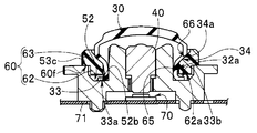
- FIG. 2 is a cross-sectional view taken along a line Y2-Y2 in FIG. 1, illustrating a relationship between a holder and a power switch provided on the holder.
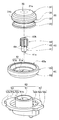
- the figure explaining the power switch arrangement hole formed in the holding base FIG. 3 is an exploded view of a main part of the power switch, and is a perspective view illustrating an operation cover, a sliding rod, a switch body, and an elastic operation member pressing member.
- FIG. 4 is an exploded view of a main part of the power switch, and is a cross-sectional view illustrating an operation cover, a sliding rod, a switch body, and an elastic operation member pressing member.
- FIG. 6F is an enlarged view of a part of FIG. 6F, illustrating a state where a space is formed between the second opening side end surface and the pressing member disposing bottom surface.
- FIG. 5 is a diagram illustrating a state in which the switch set reaches the inner side of the arrangement hole against the elastic force of the dome portion and illustrates a state in which the dome portion is elastically deformed from a natural state.
- the endoscope 1 shown in FIG. 1 is a medical device and is a portable endoscope.
- the endoscope 1 includes an endoscope main body 2 and an image display unit 3 to constitute a main part.
- the endoscope main body 2 includes an elongated insertion section 4 and an operation section 5 that is gripped by an operator.
- the operation unit 5 is a housing connected to the proximal end of the insertion unit 4.
- Reference numeral 6 denotes an image display unit holding base (hereinafter abbreviated as holding base).
- the holding base 6 is a housing arranged on the base end side of the operation unit 5.
- the holding table 6 is connected to the base end side of the operation unit 5 by a connection pipe 6p.
- the inside of the holding table 6 and the inside of the operation unit 5 are communicated by a connection pipe 6p.
- the insertion section 4 is inserted into the subject.
- the insertion section 4 includes a distal end portion 4a, a curved portion 4b, and a flexible tube portion 4c in this order from the distal end side.
- the bending portion 4b is freely bendable, for example, in two directions, up and down.
- the flexible tube portion 4c has flexibility.
- the operation section 5 is provided with a bending operation lever 7 for bending the bending section 4b.
- the bending operation lever 7 has a finger hook 7a and an arm 7b.
- the arm 7b has, for example, an L-shape.
- An operator's finger is hooked on the finger hook 7a.
- the bending portion 4b may be freely bendable in four directions, up, down, left, and right.
- the bending operation lever 7 is provided with an up / down bending operation lever and a left / right bending operation lever.
- Reference numeral 8 denotes a treatment tool insertion port.
- the treatment instrument insertion opening 8 communicates with a treatment instrument channel (not shown) that passes through the inside of the insertion section 4.
- a treatment tool such as forceps passes through the treatment tool channel from the treatment tool insertion port 8 and is guided into the body.
- a light source such as an LED that supplies illumination light to the inside of the subject is provided in the operation unit 5 of the endoscope 1.
- the illumination light emitted from the light source is emitted into the subject from the distal end surface of the distal end portion 4a by an optical fiber bundle (not shown) provided in the insertion section 4.
- an imaging unit such as a CCD or a C-MOS
- an imaging device including circuit components (not shown)
- the operation unit 5 is provided with a suction base 9 used when sucking a liquid such as a body fluid or sputum.
- a connection tube extending from a suction device is detachably attached to the suction base 9.
- Reference numeral 10 denotes a first base, which is provided with a check valve that is opened when the pressure in the operation unit 5 is higher than the external pressure.
- Reference numeral 11 denotes an image display unit.
- the image display unit 11 has an airtight internal space.
- a monitor 12 and a second base 13 are provided on the image display section 11 attached to the holding base 6.
- the monitor 12 has an LCD panel and a cover glass that covers a display surface of the LCD panel.
- the second base 13 is provided with a ventilation valve for switching between a space inside the image display unit 11 and the outside and between the outside and the outside.
- Reference numeral 20 denotes a power switch.
- the power switch 20 is one of the operation switches, and is provided on the holding base 6. When the power switch 20 is pressed, the endoscope 1 is turned on.
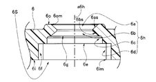
- the holding table 6 is formed with a holding table through hole (hereinafter abbreviated as a through hole) 6h that passes through the holding table internal space 6S and the outside.
- the power switch 20 is configured by integrally disposing an operation cover 30, a sliding rod 40, a switch body 50, and an elastic operation member pressing member (hereinafter, abbreviated as a pressing member) 60 in the through hole 6h.
- Reference numeral 70 denotes an electric switch, which is turned on when the sliding bar 40 moves and presses the movable contact 70a.
- Reference numeral 71 denotes a mounting plate. The mounting plate 71 is fixed to a predetermined position on the inner surface 6i of the holding table internal space 6S. The electric switch 70 is fixed to the mounting plate 71 so that the movable contact 70a can be pressed by the sliding rod 40.
- a through hole 6h of the holding base 6 shown in FIG. 3 is a power switch arrangement hole.
- the through hole 6h is referred to as a power switch arrangement hole 6h (abbreviated arrangement hole 6h).
- the arrangement hole 6h includes, in order from the outer surface 6o side, a pressing surface exposed portion 6a having a first slope 6as, a dome holding portion 6b having a second slope 6bs, and an elastic operation member pressing member disposing portion having a bottom and an opening. (Hereinafter, abbreviated as a pressing member disposing portion) 6c and a switch main body disposing portion 6d.
- Symbol a6h is the central axis of the arrangement hole 6h.
- Reference numeral 6 om denotes an outer opening
- Reference numerals 6e and 6g are bottom surfaces described later
- reference numeral 6f is a concave portion described later.
- a cylindrical operation cover 30, a solid sliding rod 40, a switch body 50, and a ring-shaped pressing member 60 are arranged in the arrangement hole 6h.
- the switch body 50 includes a central convex portion 51, a peripheral groove 52, and a disk portion 53 having a pair of protrusions 53a.
- the pair of protrusions 53a protrude outward from the outer peripheral surface 53b.
- the projection 53a is housed in a projection recess 6f formed in the switch body arrangement portion 6d of the arrangement hole 6h shown in FIG.
- the central convex portion 51 protrudes from the center of the outer end surface 53c of the disk portion 53.
- the outer end face 53c of the disk portion 53 is disposed on the main body disposing bottom surface 6e of the main body disposing portion 6d.
- the circumferential groove 52 is formed so as to surround the center convex portion 51.
- the circumferential groove 52 is set to a predetermined width and depth.
- a slope 52c is provided between the outer inner surface 52a of the circumferential groove 52 and the bottom surface 52b.
- the central convex portion 51 has a stepped accommodation hole 51h along the central longitudinal central axis.
- the accommodation hole 51h is a through hole having a small diameter hole 51a and a large diameter hole 51b.
- Reference numeral 51c denotes a step surface.
- the slide bar 40 is slidably disposed in the accommodation hole 51h.
- Reference numeral 54 shown in FIG. 5 is a switch recess.
- An electric switch 70 fixed to the mounting plate 71 is disposed in the switch recess 54.
- the sliding bar 40 shown in FIGS. 4 and 5 is hard.
- the sliding bar 40 has a small diameter portion 41 and a large diameter portion 42.
- the small diameter portion 41 is loosely fitted in the small diameter hole 51a. That is, the outer diameter of the small diameter portion 41 is set smaller than the inner diameter of the small diameter hole 51a.
- the outer diameter of the large diameter portion 42 is set to a predetermined fit with the inner diameter of the large diameter hole 51b.
- a plurality of notched grooves 44 are formed on the outer peripheral surface of the large diameter portion 42 at equal intervals in the circumferential direction.
- the notch groove 44 extends along the central longitudinal axis of the slide bar 40.
- the large-diameter portion 42 provided with the cutout groove 44 of the sliding rod 40 is a switch pressing member that can smoothly advance and retreat within the large-diameter hole 51b of the housing hole 51h.
- Reference numeral 43 denotes a contact surface. The contact surface 43 contacts the step surface 51c.
- the slide bar 40 is arranged at an initial position by the elastic force of the movable contact 70a.
- the distal end surface 41a in contact with the movable contact 70 moves the movable contact 70a against the elastic force.
- the electric switch 70 is turned on when the contact surface 43 contacts the step surface 51c.
- the distal end surface 41a of the small diameter portion 41 is a pressing surface.
- the operation cover 30 is an elastic operation member having a predetermined rubber hardness, such as elastic rubber or elastic resin.
- the operation cover 30 is formed in a predetermined tubular shape.
- the operation cover 30 mainly includes a dome portion 31 and a peripheral surface portion 32.
- the dome portion 31 forms one end of the operation cover 30.
- the dome portion 31 is provided on the outer opening 6om side of the arrangement hole 6h.
- the peripheral surface portion 32 forms the other end of the operation cover 30.
- the peripheral surface portion 32 is provided on the inner surface opening 6im side of the arrangement hole 6h communicating with the holding table internal space 6S.
- Reference numeral 33 denotes a flange portion
- reference numeral 34 denotes a first inclined portion.
- the dome portion 31 mainly has a dome portion outer surface 31a and a dome portion outer peripheral portion 31b.
- the outer peripheral portion 31b of the dome portion is a portion where the outer diameter of the dome portion 31 is the largest.
- the dome outer surface 31a has a dome shape having a curved surface that is convex outward from one end of the dome outer peripheral portion 31b.
- a region indicated by a broken line is a pressing region 35 pressed by a finger when the power switch is operated.
- the pressing area 35 is located at the center of the dome part 31.
- the inner surface of the dome portion 31 opposite to the outer surface 31a of the dome portion is a switch contact surface that can contact the end surface of the central convex portion 51.
- the switch contact surface has a substantially similar shape to the outer surface of the dome portion.
- the area indicated by reference numeral 36 in the switch contact surface is the sliding rod contact surface 36.
- the sliding rod contact surface 36 contacts the head 40 h of the sliding rod 40.
- the outer diameter of the peripheral surface 32 is smaller than the outer diameter of the outer peripheral portion 31b of the dome.
- the inner surface 37 of the peripheral surface portion 32 surrounds the outer peripheral surface 51o of the central convex portion 51 of the switch body 50.
- the inner surface 37 is close to or in contact with the outer peripheral surface 51o of the central convex portion 51.
- the flange portion 33 is provided on the side of the opening 30m of the operation cover 30.
- Reference numeral 33a denotes an end face on the flange opening side, which is located on the side of the opening 30m.
- the flange portion 33 is housed in the circumferential groove 52 of the switch body 50.
- the flange opening side end surface 33a is set on the bottom surface 52b of the circumferential groove 52.
- Reference numeral 33b denotes the other end surface of the flange.
- the other end surface 33b of the flange is opposite to the end surface 33a on the flange opening side.
- the first inclined portion 34 has an outer inclined surface 34 a extending from the outer peripheral portion 31 b of the dome portion 31 of the dome portion 31 to the peripheral surface portion 32.
- the outer inclined surface 34a of the first inclined portion 34 contacts a first inclined portion pressing surface (see reference numeral 66 in FIG. 5) of a large-diameter ring portion (reference numeral 63 in FIGS. 4 and 5) of the pressing member 60 described later.
- the outer slope 34a is a slope having a predetermined acute angle ⁇ .
- the pressing member 60 is made of, for example, resin and has an operation cover through-hole (hereinafter abbreviated as a cover hole) 61.
- the operation cover 30 is disposed in the cover hole 61.
- the pressing member 60 has a small-diameter ring portion 62 that is a first ring portion, and a large-diameter ring portion 63 that is a second ring portion.
- Reference numeral 60f is a step surface. The step surface 60f is disposed on the outer end surface 53c of the disk portion 53.
- a peripheral surface contact surface 65 and a first inclined portion pressing surface 66 are arranged on the inner surface 64 of the cover hole 61.
- the peripheral surface contact surface 65 is located on the first opening 61a side of the small diameter ring portion 62.
- the first inclined portion pressing surface 66 is located on the second opening 61b side of the large diameter ring portion 63.
- the first inclined portion pressing surface 66 is a first constraint surface of the first pressing portion.
- the first constraint surface is a slope having a predetermined acute angle ⁇ .
- the small-diameter ring portion 62 is housed in the circumferential groove 52 of the switch body 50. Specifically, the small diameter ring portion 62 is disposed in the peripheral groove 52 after the flange portion 33 of the operation cover 30 is accommodated in the peripheral groove 52. Therefore, the first opening side end surface 62a of the small diameter ring portion 62 is disposed on the flange other end surface 33b.
- the large-diameter ring portion 63 is arranged in the pressing member disposing portion 6c of the disposing hole 6h. Then, the second opening side end face 63a of the large diameter ring portion 63 is installed on the pressing member disposing bottom face 6g.
- the assembly of the power switch 20 will be described.
- the operator places the switch body 50 on the mounting plate 71 on which the electric switch 70 is fixed.
- the electric switch 70 is provided at a predetermined position in the switch recess 54.
- the worker arranges the slide bar 40 in the housing hole 51h of the switch body 50 as shown in FIG. 6B.
- the worker attaches the pressing member 60 to the operation cover 30 as shown in FIG. 6C.
- the peripheral surface contact surface 65 faces the peripheral outer surface 32a of the peripheral surface portion 32, and the outer inclined surface 34a of the first inclined portion 34 is arranged on the first inclined portion pressing surface 66.
- the flange portion 33 of the operation cover 30 to which the pressing member 60 is attached is housed in the circumferential groove 52 of the switch body 50.
- the flange opening side end surface 33a is arranged on the bottom surface 52b.
- the small-diameter ring portion 62 is accommodated in the circumferential groove 52 by disposing the step surface 60f of the pressing member 60 on the outer end surface 53c.
- the first opening side end surface 62a is placed on or opposed to the flange other end surface 33b.
- the worker introduces the switch set s20 from the inner opening 6im of the arrangement hole 6h of the holding base 6 to the outer opening 6om as shown by an arrow in FIG. 6E.
- the operator visually recognizes the positional relationship between the outer surface opening 6 om and the pressing area 35 of the dome portion 31 from the outer surface opening 6 om side of the mounting hole 6 h of the holding base 6, and attaches the switch set s 20 to the back of the mounting hole 6 h We will introduce it for.
- the dome outer peripheral portion 31b side of the dome outer surface 31a abuts on the boundary 6k between the pressing surface exposed portion 6a and the dome holding portion 6b over the entire circumference, and the switch set s20 The introduction into the arrangement hole 6h is temporarily stopped.
- the second opening side end surface 63a of the large diameter ring portion 63 is close to the pressing member disposing bottom surface 6g of the pressing member disposing portion 6c.
- the second opening side end surface 63a and the pressing member disposing bottom surface 6g face each other with a small space s therebetween.
- the switch set s20 When the switch set s20 reaches a predetermined position after the outer slope 31o contacts the second slope 6bs, the dome outer peripheral portion 31b, the first inclined portion 34, and the peripheral surface 32 are indicated by broken lines in FIG. 6H. It is elastically deformed from its natural state.
- the outer slope 31o of the second inclined portion 31c is in close contact with the second slope 6bs, and the inner surface 37 of the peripheral portion 32 is in contact with or in close contact with the outer peripheral surface 51o of the central convex portion 51.
- the second inclined portion 31c When the outer inclined surface 31o of the second inclined portion 31c is pressed after coming into contact with the second inclined surface 6bs and changes to a close contact state, the second inclined portion 31c is compressed in the direction indicated by the dashed arrow and is in the natural state indicated by the broken line. Is deformed as shown by the solid line. That is, the second inclined surface 6bs has a function as a second constraint surface of the second pressing portion that compresses and deforms the second inclined portion 31c.
- the V-shaped restraining portion 21 is formed by the first inclined portion 34 and the second inclined surface 6bs. Is formed.
- the restraining portion 21 When the switch set s20 is pushed into the rear of the arrangement hole 6h, the restraining portion 21 causes the outer slope 31o of the second slope 31c of the outer surface 31a of the dome to abut on the second slope 6bs. Then, the restraining portion 21 presses the outer inclined surface 31o of the abutted second inclined portion 31c to push the second inclined portion 31c from the outer peripheral end side toward the pressing region 35 of the dome portion 31 (the direction indicated by the broken arrow). Compress.
- the dome portion 31 in the pressing surface exposed portion 6a is balanced with a predetermined tension and elastically deformed outward to a dome shape different from the natural state which is convex.
- the mounting plate 71 is fixed to the inner surface 6i of the holding base 6 by a fixing screw (not shown).
- the power switch 20 is provided on the holder 6 as shown in FIG. 2 without using an adhesive.
- the rubber hardness of the operation cover 30 is maintained without change. That is, in the power switch 20, the pressing of the first inclined portion 34 against the outer inclined surface 34a by the first inclined portion pressing surface 66 is maintained, and the compression of the second inclined portion 31c by the second inclined surface 6bs is maintained.
- the dome portion 31 of the power switch 20 is curved outwardly in a balanced state having a predetermined tension different from the natural state. As shown in FIG. 7, the balanced dome portion 31 is maintained until the pressure difference between the outside air pressure after the autoclave sterilization and the endoscope inside the dome portion 31 reaches the predetermined pressure P. Then, the entire surface of the dome outer surface 31a receives an external pressure. For this reason, the outside air pressure is dispersed in p, and the balanced state is maintained, and as shown by the two-dot chain line, the shape is elastically deformed and the outwardly convex curved shape is maintained. When the pressure difference exceeds P, the balance is lost and the dome portion 31 is pulled.
- the pressure difference P is set in advance so as to be higher than the pressure difference Pa at which the switch cover of the push-type switch device described in the above-mentioned publication is drawn in after the autoclave sterilization is completed.
- the switch cover is set so that the flexibility is lowered to be higher than the pressure difference Pb at which the switch cover is drawn.
- the dome portion 31 is maintained in a dome shape different from the natural state.
- the user when the user observes with the endoscope 1, the user operates the power switch 20. At this time, the user presses the pressing area 35 of the operation cover 30 with the finger f as shown in FIG. At this time, as shown in FIG. 7, the pressing region 35 of the dome outer surface 31a is pressed with the pressing force of Pw as shown by the arrow Y7.
- the dome portion 31 having a predetermined tension different from the natural state maintains the dome shape different from the natural state until the pressing force reaches Pp.
- the dome portion 31 maintains the outwardly curved state until the pressing force reaches P1.
- the force Pp is larger than the initial operation force p1 of the pressing switch device disclosed in the above-mentioned publication, and is larger than the initial operation force p2 of the pressing switch device that avoids the drawback of the switch cover being pulled in.
- the electric switch is turned on when the operation force amount Pw reaches, for example, a standard value in the push-type switch device disclosed in the official gazette.
- the electric switch is turned on when the operation force amount Pw far exceeds the standard value.
- the dome portion 31 is held in a curved shape without being elastically deformed until the operation force amount Pw exceeds Pp.
- the operation force amount Pw exceeds Pp
- the balance in the vicinity of the pressing area 35 is broken as shown by the broken line in FIG. 7, and the dome portion 31 is deformed.
- the sliding bar 40 is moved, and the movable contact 70a of the electric switch 70 is deformed with the movement of the sliding prevention member 40, so that the electric switch 70 is turned on.
- the operation force amount Pw when the electric switch 70 is on is set to be equal to or less than a predetermined value.
- the dome portion 31 of the power switch 20 is compressed so as not to be pulled in until it reaches the pressure difference P higher than the pressure differences Pa and Pb, and has a predetermined tension different from the natural state. It has a curved dome shape.
- the initial operation force amount Pp for deforming the dome portion 31 is the initial operation force amount P1 of the push-type switch device disclosed in the above-mentioned publication, and an improved switch which can avoid the trouble. Although it is larger than the initial operation force P2 of the push-type switch device provided with the cover, when the power switch 20 is on, it is within the standard value similarly to the operation force amount of the conventional push-type switch device.
- the head 40h of the sliding bar 40 is separated from the sliding bar contact surface 36 of the operation cover 30 by a predetermined distance.
- the sliding bar 40 is slidably disposed in the housing hole 51h.
- the electric switch 70 can be uniformly operated by operating the power switch 20.
- the operating force exceeds the standard value when the electric switch is turned on, as shown by the two-dot chain line in FIG.
- the operation switch is a power switch 20 provided on the holding base 6 of the endoscope 1.
- the operation switch is not limited to the power switch of the endoscope 1, and is, for example, a freeze switch for generating a freeze signal, a release switch for generating a release signal, and an observation mode switching switch, which are provided in an operation section of the endoscope. Or an electric switch that outputs an electric signal.
- the operation switch may be a power switch or an electric switch provided on a housing of a medical device other than the endoscope.
Landscapes
- Health & Medical Sciences (AREA)
- Life Sciences & Earth Sciences (AREA)
- Surgery (AREA)
- Engineering & Computer Science (AREA)
- Biomedical Technology (AREA)
- Heart & Thoracic Surgery (AREA)
- Pathology (AREA)
- Radiology & Medical Imaging (AREA)
- Nuclear Medicine, Radiotherapy & Molecular Imaging (AREA)
- Biophysics (AREA)
- Physics & Mathematics (AREA)
- Optics & Photonics (AREA)
- Medical Informatics (AREA)
- Molecular Biology (AREA)
- Animal Behavior & Ethology (AREA)
- General Health & Medical Sciences (AREA)
- Public Health (AREA)
- Veterinary Medicine (AREA)
- Mechanical Engineering (AREA)
- Push-Button Switches (AREA)
Abstract
操作スイッチは、弾性力を備える、筐体貫通孔の外面開口側に配置される自然状態で外方に凸状で押圧操作されて弾性変形するドーム部、および、フランジ部を含む周面部を有する弾性操作部材と、ドーム部の押圧領域を変形させることによって移動する押圧部材と、電気スイッチが配置されるスイッチ用凹部、および、押圧部材が収容される収容孔を有する中央凸部を備えたスイッチ本体と、スイッチ本体に設置されて自然状態の弾性操作部材を押圧して自然状態の弾性操作部材の予め定めた部分を押圧してドーム部を弾性変形させる第2リング部、を配置した弾性操作部材押圧部材と、を具備する。
Description
本発明は、押圧されてオンになる電気スイッチと、該スイッチを押圧する際に弾性変形される弾性操作部材と、を備える操作スイッチ、操作スイッチが設けられている医療機器、および、操作スイッチが設けられている内視鏡に関する。
医療用の内視鏡は一般に、体腔内に挿入される細長な挿入部と、挿入部の基端側に設けられた操作部と、を有している。
挿入部の先端部には観察光学系、照明光学系が設けられている。また、挿入部には観察性能の向上および被検体内への挿入性の向上を図る目的で湾曲自在な湾曲部を設けたものがある。また、挿入部には該挿入部内に送気、送水または吸引のための流体管路を設けたものがある。
挿入部の先端部には観察光学系、照明光学系が設けられている。また、挿入部には観察性能の向上および被検体内への挿入性の向上を図る目的で湾曲自在な湾曲部を設けたものがある。また、挿入部には該挿入部内に送気、送水または吸引のための流体管路を設けたものがある。
操作部には湾曲部を湾曲させる湾曲操作装置が設けられている。また、操作部には電気的なスイッチとして内視鏡画像の停止、内視鏡画像の記録、照明光の切替、等を指示する複数の押しボタンスイッチが設けられている。また、操作部には送気の制御、送水の制御、吸引の制御をするための流体制御ボタンが設けられている。
PCT特許出願WO2013/154106号公報の図7等には操作部本体に設けられた押圧式のスイッチ装置が示されている。スイッチ装置は、操作部本体内に配設されたスイッチ部を配置したスイッチ基板と、操作部本体外からの操作者のスイッチ操作をスイッチ基板に伝達するスイッチカバーと、を有している。
スイッチカバーは、例えば、基部と、筒状部と、第1の変形部及び第2の変形部と、応力伝達部と、を有している。応力伝達部は、突起状の操作入力部と、入力された外部応力をスイッチ部に伝達する押圧部と、を備えている。スイッチカバーは、柔軟な樹脂等により一体成形されて要部が設けられている。この操作入力部を構成する3つの平面のうち1つは、操作者の押圧による外部応力を入力することが可能な被押圧面である。
上述した押圧式のスイッチ装置によれば、操作者は、まずスイッチ装置の被押圧面を押圧して操作入力部に外部応力を入力する。すると、第1,第2の変形部が変形されて操作入力部が傾倒し、押圧部の端部がスイッチ部に当接する。これにより、スイッチ部の図示しない2つの接点が電気的に接続され、スイッチ装置がオンになる。なお、第1の被押圧面が押圧から解放されると、操作入力部が起立されてスイッチ装置がオフに戻る。
近年、医療用の内視鏡は、使用後、オートクレーブ滅菌される。オートクレーブ滅菌において、内視鏡は、チャンバー内に放置される。チャンバー内の内視鏡は、プレバキューム工程、高圧蒸気滅菌工程、乾燥工程を経てオートクレーブ滅菌処理される。オートクレーブ滅菌終了後、内視鏡は、大気中に放置される。
近年、医療用の内視鏡は、使用後、オートクレーブ滅菌される。オートクレーブ滅菌において、内視鏡は、チャンバー内に放置される。チャンバー内の内視鏡は、プレバキューム工程、高圧蒸気滅菌工程、乾燥工程を経てオートクレーブ滅菌処理される。オートクレーブ滅菌終了後、内視鏡は、大気中に放置される。
しかしながら、上述した押圧式のスイッチ装置においては、オートクレーブ滅菌終了後、内視鏡を大気中に放置した際、スイッチカバーが引き込まれて例えば電源スイッチがオンになるおそれがある。これは、滅菌中に内視鏡内部が陰圧になり、滅菌後大気中に放置されたときに相対的に電源ボタンの内側の圧力よりも外側の気圧が高いためである。
この不具合は、スイッチカバーの柔軟性を低下させて第1の変形部および第2の変形部が変形されないようにすることによって回避することが可能である。しかし、スイッチカバーの柔軟性が低下すると、操作力量が増大して操作性に悪影響を及ぼすおそれ、操作力量が規格値を超えるおそれがある。
なお、内視鏡がバッテリ駆動タイプの場合、オートクレーブ滅菌終了後に電鍵スイッチがオンになることによって電力残量の低下、バッテリ切れ等の不具合が発生する。
本発明は上記事情に鑑みてなされたものであり、オートクレーブ滅菌終了後、大気中に放置することによってスイッチ装置がオンに切り替えられることを防止しつつ操作性に優れた操作スイッチ、操作スイッチが設けられている医療機器、および、操作スイッチが設けられている内視鏡を提供することを目的にしている。
本発明の一態様の操作スイッチは、予め定めた弾性力を備えた弾性部材の一端側に設けられている自然状態では外方に凸状に形成され、筐体に形成された外部と筐体内部空間とを通じる筐体貫通孔の外面開口側の押圧面露出部には前記自然状態とは異なる予め定めた張りを持った釣合い状態で外方に凸曲面なドーム形状に弾性変形されて配置されるドーム部、および、他端側に設けられているフランジ部を含む周面部を有する、弾性操作部材と、前記ドーム部の押圧領域を内方側に変形させていくことによって移動される、押圧操作されることで電気信号を発生する電気スイッチを押圧する、押圧部材と、前記電気スイッチが配置されるスイッチ用凹部、および、前記押圧部材が摺動自在に収容される収容孔を有し、前記弾性操作部材の周面部の内面が配置される外周面を有する中央凸部を備えたスイッチ本体と、を具備している。
本発明の一態様の医療機器は、前記操作スイッチが術者によって把持される筐体に設けられている。
本発明の一態様の内視鏡は、操作スイッチが術者によって把持される操作部または該操作部の基端側に配置された保持台に設けられている。
以下、図面を参照して本発明の実施の形態を説明する。
なお、以下の説明に用いる各図において、各構成要素を図面上で認識可能な程度の大きさとするため、構成要素毎に縮尺を異ならせてあるものもある。すなわち、本発明は、これらの図に記載された構成要素の数量、構成要素の形状、構成要素の大きさの比率および各構成要素の相対的な位置関係のみに限定されるものではない。
なお、以下の説明に用いる各図において、各構成要素を図面上で認識可能な程度の大きさとするため、構成要素毎に縮尺を異ならせてあるものもある。すなわち、本発明は、これらの図に記載された構成要素の数量、構成要素の形状、構成要素の大きさの比率および各構成要素の相対的な位置関係のみに限定されるものではない。
図1に示す内視鏡1は医療機器であって、携帯式の内視鏡である。内視鏡1は、内視鏡本体2と、画像表示部3と、を具備して主要部が構成されている。
内視鏡本体2は、細長な挿入部4と、術者によって把持される操作部5と、を備える。操作部5は、挿入部4の基端側に連設された筐体である。
内視鏡本体2は、細長な挿入部4と、術者によって把持される操作部5と、を備える。操作部5は、挿入部4の基端側に連設された筐体である。
符号6は画像表示部保持台(以下、保持台と略記する)である。保持台6は、操作部5の基端側に配置された筐体である。保持台6は、連結パイプ6pによって操作部5の基端側に連結されている。保持台6の内部と操作部5の内部とは連結パイプ6pによって通じている。
挿入部4は、被検体内に挿入される。挿入部4は、先端側から順に先端部4aと、湾曲部4bと、可撓管部4cと、を具備している。湾曲部4bは例えば上下の二方向に湾曲自在である。可撓管部4cは可撓性を有している。
操作部5には湾曲部4bを湾曲させるための湾曲操作レバー7が設けられている。湾曲操作レバー7は、指掛部7aと腕部7bとを有する。腕部7bは例えばL字型形状である。指掛部7aには術者の指が掛けられる。
湾曲部4bは上下左右の四方向に湾曲自在であってもよい。その場合、湾曲操作レバー7に上下湾曲操作レバーと左右湾曲操作レバーとを設ける。
湾曲部4bは上下左右の四方向に湾曲自在であってもよい。その場合、湾曲操作レバー7に上下湾曲操作レバーと左右湾曲操作レバーとを設ける。
符号8は処置具挿通口である。処置具挿通口8は、挿入部4の内部を挿通する処置具チャンネル(不図示)に通じている。鉗子等の処置具は、処置具挿通口8から処置具チャンネル内を通過して体内に導出される。
なお、本実施形態において内視鏡1の操作部5内には被検体内に照明光を供給するLED等の光源(不図示)が設けられている。光源から照射される照明光は、挿入部4内に設けられた光ファイバ束(不図示)によって先端部4aの先端面から被検体内に照射されるようになっている。
また、操作部5または保持台6内または挿入部4内にはCCD、あるいは、C-MOS等の撮像部(不図示)、回路部品(不図示)を含む撮像装置(不図示)が内蔵されている。また、操作部5には体液、痰等の液体を吸引する際に用いられる吸引口金9が設けられている。吸引口金9には図示しない吸引装置から延出する接続チューブが着脱自在である。
符号10は第1の口金であり、操作部5内の圧力が外部の圧力よりも大きいときに開放される逆止弁を備えている。符号11は画像表示部である。画像表示部11は気密状態にされた内部空間を有している。
保持台6に取り付けられた画像表示部11にはモニタ12、第2の口金13が設けられている。モニタ12は、LCDパネルと、該LCDパネルの表示面を覆うカバーガラスとを有している。第2の口金13は、画像表示部11内の空間と外部との流通と遮断とを切り替える通気弁を具備している。
符号20は電源スイッチである。本実施形態において、電源スイッチ20は操作スイッチの一つであり、保持台6に設けられている。電源スイッチ20が押圧されることで内視鏡1はオンになる。
図2に示すように保持台6には保持台内部空間6Sと外部とを通じる保持台貫通孔(以下、貫通孔と略記する)6hが形成されている。電源スイッチ20は、貫通孔6hに対して操作カバー30、摺動棒40、スイッチ本体50、弾性操作部材押圧部材(以下、押圧部材と略記する)60を一体に配置して構成されている。
符号70は電気スイッチであり、摺動棒40が移動して可動接点70aを押圧することでオンになる。符号71は取付板である。取付板71は保持台内部空間6Sの内面6iの予め定めた位置に固定される。電気スイッチ70は、摺動棒40によって可動接点70aを押圧できるように取付板71に固設される。
図3に示す保持台6の貫通孔6hは電源スイッチ配設孔である。以下、貫通孔6hを電源スイッチ配設孔6h(略記して配設孔6h)と記載する。
配設孔6hは、外面6o側から順に、第1斜面6asを有する押圧面露出部6a、第2斜面6bsを有するドーム部保持部6b、有底で開口を有する弾性操作部材押圧部材配設部(以下、押圧部材配設部と略記する)6c、および、スイッチ本体配設部6d、を備えている。
符号a6hは配設孔6hの中心軸である。符号6omは外面開口、符号6imは内面開口である。符号6e、6gは後述する底面で有り、符号6fは後述する凹部である。
配設孔6hは、外面6o側から順に、第1斜面6asを有する押圧面露出部6a、第2斜面6bsを有するドーム部保持部6b、有底で開口を有する弾性操作部材押圧部材配設部(以下、押圧部材配設部と略記する)6c、および、スイッチ本体配設部6d、を備えている。
符号a6hは配設孔6hの中心軸である。符号6omは外面開口、符号6imは内面開口である。符号6e、6gは後述する底面で有り、符号6fは後述する凹部である。
図4、図5に示すように配設孔6hには、筒状の操作カバー30、中実な摺動棒40、スイッチ本体50、および、リング状の押圧部材60が配置される。
スイッチ本体50は、中央凸部51、周溝52、一対の突起53aを有する円板部53を備えている。一対の突起53aは外周面53bから外方に突出している。突起53aは、図3に示す配設孔6hのスイッチ本体配設部6dに形成された突起用凹部6fに収容される。
中央凸部51は、円板部53の外方側端面53cの中央から突出している。円板部53の外方側端面53cは、本体配設部6dの本体配設用底面6e上に配置される。
周溝52は、中央凸部51の周囲を囲むように形成されている。周溝52は、予め定めた幅および深さに設定されている。周溝52の外方内面52aと底面52bとの間には斜面52cが設けられている。
周溝52は、中央凸部51の周囲を囲むように形成されている。周溝52は、予め定めた幅および深さに設定されている。周溝52の外方内面52aと底面52bとの間には斜面52cが設けられている。
中央凸部51は中央の長手中心軸に沿って段付き形状の収容孔51hを備えている。収容孔51hは、小径孔51aと大径孔51bとを有する貫通孔である。符号51cは段差面である。収容孔51h内には摺動棒40が摺動自在に配置される。
図5に示す符号54はスイッチ用凹部である。スイッチ用凹部54内には取付板71に固設された電気スイッチ70が配置される。
図5に示す符号54はスイッチ用凹部である。スイッチ用凹部54内には取付板71に固設された電気スイッチ70が配置される。
図4、図5に示す摺動棒40は硬質である。摺動棒40は、細径部41と太径部42とを有している。細径部41は小径孔51a内に遊嵌される。つまり、細径部41の外径は小径孔51aの内径に比べて小さく設定されている。
これに対して、太径部42の外径は大径孔51bの内径に対して予め定めた嵌め合いに設定されている。大径部42の外周面には複数の切欠溝44が周方向に等間隔で形成されている。切欠溝44は、摺動棒40の中央長手軸に沿って延びている。摺動棒40の切欠溝44を備える大径部42は、収容孔51hの大径孔51b内をスムーズに進退移動可能なスイッチ押圧部材である。符号43は当接面である。当接面43が段差面51cに当接する。
摺動棒40は、収容孔51h内を移動して当接面43が段差面51cに当接して移動が停止される。小径部41の先端面41aは電気スイッチ70の可動接点70aに当接する。
摺動棒40は、可動接点70aの弾性力によって初期位置に配置される。
摺動棒40が初期位置において、当接面43は段差面51cから離間している。摺動棒40の頭部40hは操作カバー30の摺動棒当接面36から予め定めた距離、離間されている。
そして、摺動棒40の移動に伴って可動接点70に当接されている先端面41aが該可動接点70aを弾性力に抗して移動させていく。
なお、電気スイッチ70は、当接面43が段差面51cに当接してオンになる。小径部41の先端面41aは押圧面である。
なお、電気スイッチ70は、当接面43が段差面51cに当接してオンになる。小径部41の先端面41aは押圧面である。
操作カバー30は弾性ゴム、弾性樹脂等、予め定めたゴム硬度の弾性操作部材である。操作カバー30は、予め定めた筒状に形成されている。
操作カバー30は、主にドーム部31と周面部32とを備えている。ドーム部31は、操作カバー30の一端側を形作る。ドーム部31は、配設孔6hの外面開口6om側に設けられる。周面部32は、操作カバー30の他端側を形作る。周面部32は配設孔6hの保持台内部空間6Sに通じる内面開口6im側に設けられる。
なお、符号33はフランジ部、符号34は第1傾斜部である。
操作カバー30は、主にドーム部31と周面部32とを備えている。ドーム部31は、操作カバー30の一端側を形作る。ドーム部31は、配設孔6hの外面開口6om側に設けられる。周面部32は、操作カバー30の他端側を形作る。周面部32は配設孔6hの保持台内部空間6Sに通じる内面開口6im側に設けられる。
なお、符号33はフランジ部、符号34は第1傾斜部である。
ドーム部31は、主にドーム部外表面31aとドーム部外周部31bとを有する。ドーム部外周部31bはドーム部31の最も外径が大きな部位である。ドーム部外表面31aは、ドーム部外周部31bの一端側から外方側に凸曲面のドーム形状である。
ドーム部外表面31a上において、破線で示す領域は電源スイッチ操作時に手指によって押圧される押圧領域35である。押圧領域35はドーム部31の中央に位置する。
ドーム部外表面31aの反対側面であるドーム部31の内面は中央凸部51の端面に当接可能なスイッチ当接面である。スイッチ当接面は、ドーム部外表面に略相似形状である。そして、スイッチ当接面のうち、符号36に示す領域は摺動棒当接面36である。摺動棒当接面36は、摺動棒40の頭部40hに当接する。
周面部32の周面外径はドーム部外周部31bの外径より小径である。周面部32の内面37は、スイッチ本体50の中央凸部51の外周面51oを囲繞する。内面37は、中央凸部51の外周面51oに対して近接あるいは当接する。
フランジ部33は、操作カバー30の開口30m側に設けられている。符号33aはフランジ開口側端面であり、開口30m側に位置している。フランジ部33は、スイッチ本体50の周溝52内に収容される。フランジ開口側端面33aは周溝52の底面52b上に設置されるようになっている。
符号33bはフランジ他端面である。フランジ他端面33bはフランジ開口側端面33aの反対面である。
符号33bはフランジ他端面である。フランジ他端面33bはフランジ開口側端面33aの反対面である。
第1傾斜部34は、ドーム部31のドーム部外周部31bから周面部32に至る外斜面34aを有する。第1傾斜部34の外斜面34aには後述する押圧部材60の大径リング部(図4、図5等の符号63)の第1傾斜部押圧面(図5の符号66参照)が当接する。外斜面34aは予め定めた鋭角な角度θの斜面である。
押圧部材60は例えば樹脂製で操作カバー用貫通孔(以下、カバー用孔と略記する)61を有している。カバー用孔61内には操作カバー30が配置される。押圧部材60は、第1リング部である小径リング部62と、第2リング部である大径リング部63と、を有している。符号60fは段差面である。段差面60fは、円板部53の外方側端面53c上に配置される。
カバー用孔61の内面64には周面部当接面65と第1傾斜部押圧面66とが配置されている。周面部当接面65は小径リング部62の第1開口61a側に位置している。第1傾斜部押圧面66は大径リング部63の第2開口61b側に位置している。
第1傾斜部押圧面66は、第1押圧部の第1拘束面である。第1拘束面は予め定めた鋭角な角度θの斜面である。
第1傾斜部押圧面66は、第1押圧部の第1拘束面である。第1拘束面は予め定めた鋭角な角度θの斜面である。
小径リング部62はスイッチ本体50の周溝52内に収容される。具体的に、小径リング部62は、周溝52内に操作カバー30のフランジ部33が収容されたうえで、該周溝52内に配置される。したがって、小径リング部62の第1開口側端面62aはフランジ他端面33b上に配置される。
一方、大径リング部63は配設孔6hの押圧部材配設部6c内に配置されるようになっている。そして、大径リング部63の第2開口側端面63aは押圧部材配設用底面6g上に設置される。
ここで電源スイッチ20の組み付けを説明する。
まず、作業者は、図6Aに示すように電気スイッチ70が固設された取付板71にスイッチ本体50を配置する。電気スイッチ70は、スイッチ用凹部54内の所定の位置に設けられる。その後、作業者は、図6Bに示すようにスイッチ本体50の収容孔51h内に摺動棒40を配置する。
まず、作業者は、図6Aに示すように電気スイッチ70が固設された取付板71にスイッチ本体50を配置する。電気スイッチ70は、スイッチ用凹部54内の所定の位置に設けられる。その後、作業者は、図6Bに示すようにスイッチ本体50の収容孔51h内に摺動棒40を配置する。
次に、作業者は、図6Cに示すように操作カバー30に押圧部材60を取り付ける。このとき、周面部当接面65を周面部32の周外面32aに対向させると共に、第1傾斜部押圧面66上に第1傾斜部34の外斜面34aを配置させておく。
次いで、図6Dに示すように押圧部材60が取り付けられた操作カバー30のフランジ部33をスイッチ本体50の周溝52内に収容する。このとき、フランジ開口側端面33aを底面52b上に配置する。 そのうえで、押圧部材60の段差面60fを外方側端面53c上に配置させて小径リング部62を周溝52内に収容する。このとき、第1開口側端面62aはフランジ他端面33b上に載置、または、対向される。
この結果、スイッチ本体50に電気スイッチ70、操作カバー30、摺動棒40、押圧部材60を配置したスイッチセットs20となる。
次いで、作業者は、図6Eの矢印に示すようにスイッチセットs20を保持台6の配設孔6hの内面開口6imから外面開口6omに向けて導入する。このとき、作業者は保持台6の配設孔6hの外面開口6om側から該外面開口6omとドーム部31の押圧領域35との位置関係を視認しつつスイッチセットs20を配設孔6hの奥方に向けて導入していく。
すると、図6Fに示すようにドーム部外表面31aのドーム部外周部31b側が全周に渡って押圧面露出部6aとドーム部保持部6bとの境界部6kに当接し、該スイッチセットs20の配設孔6hへの導入が一旦停止される。
このとき、図6Gに示すように大径リング部63の第2開口側端面63aが押圧部材配設部6cの押圧部材配設用底面6gに近接している。言い換えれば、第2開口側端面63aと押圧部材配設用底面6gとが僅かな空間sを挟んで対向している。
この後、作業者は、スイッチセットs20を操作カバー30の弾性力に抗してさらに矢印Y6Gに示す配設孔6hの奥方に押し込む。すると、第1傾斜部押圧面66上に位置する第1傾斜部34、ドーム部外周部31bも奥方に移動される。
すると、図6Hに示すようにドーム部外表面31aとドーム部外周部31bとの間に位置する第2傾斜部31cの外斜面31oがドーム部保持部6bの第2斜面6bsに当接したうえで、スイッチセットs20が配設孔6h内の予め定めた位置に到達する。
外斜面31oが第2斜面6bsに当接したうえでスイッチセットs20が予め定めた位置に到達するとき、ドーム部外周部31b、第1傾斜部34、周面部32は、図6Hの破線に示す自然状態から弾性変形される。
この結果、第2傾斜部31cの外斜面31oが第2斜面6bsに密着するとともに周面部32の内面37が中央凸部51の外周面51oに当接、あるいは、密着する。
第2傾斜部31cの外斜面31oが第2斜面6bsに当接した後に押圧されて密着状態に変化するとき、第2傾斜部31cが破線の矢印に示す方向に圧縮されて破線に示す自然状態から実線に示すように変形される。
つまり、第2斜面6bsは、第2傾斜部31cを圧縮しつつ変形させる第2押圧部の第2拘束面としての機能を有している。
つまり、第2斜面6bsは、第2傾斜部31cを圧縮しつつ変形させる第2押圧部の第2拘束面としての機能を有している。
そして、スイッチセットs20が予め定めた位置に到達しているとき、第1傾斜部押圧面66による第1傾斜部34の外斜面34aに対する押圧が維持されるとともに、第2斜面6bsによる第2傾斜部31cに対する圧縮が維持される。
なお、図6Gに示したように第2開口側端面63aが押圧部材配設用底面6gに近接して対向したとき、第1傾斜部34と第2斜面6bsとによってV字形状の拘束部21が形作られる。
拘束部21は、スイッチセットs20が配設孔6hの奥方に押し込まれる際、ドーム部外表面31aの第2傾斜部31cの外斜面31oを第2斜面6bsに当接させる。
そのうえで拘束部21は、当接した第2傾斜部31cの外斜面31oを押圧して該第2傾斜部31cを外周端側からドーム部31の押圧領域35方向(破線の矢印に示す方向)に圧縮していく。
そのうえで拘束部21は、当接した第2傾斜部31cの外斜面31oを押圧して該第2傾斜部31cを外周端側からドーム部31の押圧領域35方向(破線の矢印に示す方向)に圧縮していく。
このことによって、押圧面露出部6a内のドーム部31は、予め定めた張りを持って釣り合って外方に凸形状な自然状態とは異なるドーム形状に弾性変形される。
この後、取付板71が保持台6の内面6iに固定ねじ(不図示)によって固定される。このことによって、接着剤を使用すること無く前記図2に示したように保持台6に電源スイッチ20が設けられる。このため、操作カバー30のゴム硬度が変化すること無く維持される。つまり、電源スイッチ20において、第1傾斜部押圧面66による第1傾斜部34の外斜面34aに対する押圧が維持され続けるとともに、第2斜面6bsによる第2傾斜部31cに対する圧縮が維持され続ける。
ここで、電源スイッチ20の作用を説明する。
電源スイッチ20のドーム部31は、自然状態と異なる予め定めた張りを持った釣合い状態で外方に湾曲されている。この釣合い状態のドーム部31は、オートクレーブ滅菌終了後の外気圧とドーム部31の内部側である内視鏡内部の圧力差が予め定めた圧力Pに到達するまでの間、図7に示すようにドーム部外表面31aの全面で外気圧を受ける。このため、外気圧がpに分散されて釣合い状態を保持して二点鎖線に示すように弾性変形されつつ外方に凸状な湾曲形状を維持する。
そして、圧力差がPを越えると釣合いが崩されてドーム部31が引き込まれる。
電源スイッチ20のドーム部31は、自然状態と異なる予め定めた張りを持った釣合い状態で外方に湾曲されている。この釣合い状態のドーム部31は、オートクレーブ滅菌終了後の外気圧とドーム部31の内部側である内視鏡内部の圧力差が予め定めた圧力Pに到達するまでの間、図7に示すようにドーム部外表面31aの全面で外気圧を受ける。このため、外気圧がpに分散されて釣合い状態を保持して二点鎖線に示すように弾性変形されつつ外方に凸状な湾曲形状を維持する。
そして、圧力差がPを越えると釣合いが崩されてドーム部31が引き込まれる。
なお、圧力差Pは、予めオートクレーブ滅菌終了後に前述した公報に示されている押圧式のスイッチ装置のスイッチカバーが引き込まれる圧力差Paよりも高くなるように設定してある。加えて、スイッチカバーが引き込まれる不具合を回避するために柔軟性を低下させたスイッチカバーが引き込まれる圧力差Pbよりも高くなるように設定してある。
したがって、ドーム部外表面31aに圧力差Pa、Pbが生じてもドーム部31は自然状態と異なるドーム形状で維持される。
一方、ユーザが内視鏡1による観察を行う際、該ユーザが電源スイッチ20が操作する。この際ユーザは、図8に示すように手指fで操作カバー30の押圧領域35を押圧する。
このとき、図7に示すようにドーム部外表面31aの押圧領域35がPwの押圧力で矢印Y7に示すように押圧される。自然状態とは異なる予め定めた張りを持ったドーム部31は、押圧する力量がPpに到達するまで自然状態と異なるドーム形状を維持する。
このとき、図7に示すようにドーム部外表面31aの押圧領域35がPwの押圧力で矢印Y7に示すように押圧される。自然状態とは異なる予め定めた張りを持ったドーム部31は、押圧する力量がPpに到達するまで自然状態と異なるドーム形状を維持する。
言い換えれば、図9に示すように押圧する力量がP1に到達するまでドーム部31は外方に湾曲した状態を維持する。
この力量Ppは、前述した公報に示されている押圧式のスイッチ装置の初期操作力量p1より大きく、スイッチカバーが引き込まれる不具合を回避した押圧式のスイッチ装置の初期操作力量p2より大きい。
なお、図9の破線に示すように公報に示された押圧式のスイッチ装置では操作力量Pwが例えば規格値に到達したとき電気スイッチがオンになる。一方、二点鎖線に示すようにスイッチカバーが引き込まれる不具合を回避した押圧式のスイッチ装置では、操作力量Pwが規格値をはるかに超えて電気スイッチがオンになる。
図9に示すように操作力量PwがPpを越えるまではドーム部31は弾性変形すること無く湾曲形状に保持される。そして、操作力量PwがPpを越えると図7の破線に示すように押圧領域35近傍の釣合いが崩されてドーム部31が変形する。
釣合いが崩れると図9の実線に示すように、ドーム部31の摺動棒当接面36はPpより小さな力量で摺動棒40の頭部40hに近づけられる。そして、摺動棒当接面36が頭部40hに到達した後、実線に示すようにユーザによる摺動棒40の押圧が開始される。
この結果、摺動棒40が移動され、この摺動防40の移動に伴って電気スイッチ70の可動接点70aが変形されて電気スイッチ70がオンになる。
なお、図9に示すように電気スイッチ70がオンのときの操作力量Pwは予め定めた規定値と同等又はそれ以下に設定してある。また、ユーザが手指fを操作カバー30から離すことによって操作カバー30は元の湾曲形状に復元されて、可動接点71が元の位置に戻ってオフになる。
なお、図9に示すように電気スイッチ70がオンのときの操作力量Pwは予め定めた規定値と同等又はそれ以下に設定してある。また、ユーザが手指fを操作カバー30から離すことによって操作カバー30は元の湾曲形状に復元されて、可動接点71が元の位置に戻ってオフになる。
このように、電源スイッチ20のドーム部31を圧力差Pa、Pbより高い圧力差Pに到達するまで引き込まれることが無いように圧縮して自然状態とは異なる予め定めた張りを持たった外方に湾曲したドーム形状にしている。
この結果、オートクレーブ滅菌終了後の内視鏡1において、電源スイッチ20のドーム部31が引き込まれることによって電源スイッチ20がオンになる不具合をより確実に防止できる。
また、電源スイッチ20を操作した際、ドーム部31を変形させる初期操作力量Ppが前述した公報に示された押圧式のスイッチ装置の初期操作力量P1、不具合の回避を可能にした改良型のスイッチカバーを備えた押圧式のスイッチ装置の初期操作力量P2より大きくなるが、電源スイッチ20がオンのときには従来の押圧式のスイッチ装置の操作力量と同様に規格値内である。
これらの結果、オートクレーブ滅菌終了後、大気中に放置して外気圧と内部との圧力差が生じてスイッチ装置がオンに切り替えられることを防止しつつ操作性に優れた電源スイッチを実現できる。
また、電源スイッチ20において、摺動棒40は初期位置のとき該摺動棒40の頭部40hが操作カバー30の摺動棒当接面36から予め定めた距離、離間している。また、摺動棒40は収容孔51h内には摺動自在に配置されている。
このため、操作カバー30のドーム部31が予め設定したように変形されたときに摺動棒40が移動される。したがって、電気スイッチ70を電源スイッチ20の操作によって均一に操作することができる。
電源スイッチ20において第1傾斜部押圧面66による第1傾斜部34の外斜面34aに対する押圧が維持され続けるとともに、第2斜面6bsによる第2傾斜部31cに対する圧縮が維持され続ける。したがって、電源スイッチ20を操作中、第2傾斜部31cの外斜面31oがドーム部保持部6bの第2斜面6bsに密着して外部との水密を確実に保持される。
なお、前述した改良型のスイッチカバーを備えた押圧式のスイッチ装置においては図9の二点鎖線で示すように電気スイッチがオンの際に操作力量が規格値を超えてしまう。
また、本実施形態においては、操作スイッチを内視鏡1の保持台6に設けられた電源スイッチ20としている。しかし、操作スイッチは内視鏡1の電源スイッチに限定されるものでは無く、例えば内視鏡の操作部に設けられるフリーズ信号を発生させるフリーズスイッチ、レリーズ信号を発生させるレリーズスイッチ、観察モード切替スイッチ等の電気信号を出力する電気スイッチであってもよい。また、操作スイッチは、内視鏡以外の医療機器の筐体に設けられる電源スイッチ、あるいは、電気スイッチであってもよい。
本発明は、上述した実施形態に限定されるものではなく、発明の要旨を逸脱しない範囲において種々変更あるいは応用が可能である。
Claims (9)
- 予め定めた弾性力を備えた弾性部材の一端側に設けられている自然状態では外方に凸状に形成され、筐体に形成された外部と筐体内部空間とを通じる筐体貫通孔の外面開口側の押圧面露出部には前記自然状態とは異なる予め定めた張りを持った釣合い状態で外方に凸曲面なドーム形状に弾性変形されて配置されるドーム部、および、他端側に設けられているフランジ部を含む周面部を有する、弾性操作部材と、
前記ドーム部の押圧領域を内方側に変形させていくことによって移動される、押圧操作されることで電気信号を発生する電気スイッチを押圧する、押圧部材と、
前記電気スイッチが配置されるスイッチ用凹部、および、前記押圧部材が摺動自在に収容される収容孔を有し、前記弾性操作部材の周面部の内面が配置される外周面を有する中央凸部を備えたスイッチ本体と、
を具備することを特徴とする操作スイッチ。 - 前記スイッチ本体に設置される第1リング部、および、前記筐体貫通孔の押圧部材配設部に設置されて自然状態の前記弾性操作部材の予め定めた部分を押圧して前記ドーム部を弾性変形させる第2リング部、を配置した弾性操作部材押圧部材を具備し、
前記自然状態の弾性操作部材のドーム部は、前記第2リング部が前記押圧部材配設部に設置された際に該第2リング部の第1傾斜部押圧面と前記筐体貫通孔のドーム部保持部の第2斜面とが形作る拘束部によって押圧されて、
前記自然状態とは異なるドーム形状に弾性変形されて前記押圧面露出部に配置される
ことを特徴とする請求項1に記載の操作スイッチ。 - 前記押圧面露出部に配置された前記ドーム部は、
外気圧と該ドーム部の内部側の圧力との圧力差が予め定めた圧力に到達するまでの間、当該ドーム部の外表面側にかかる外気圧を該外表面の全面で受けることによって弾性変形して外方に凸状な自然状態と異なるドーム形状を維持する、
ことを特徴とする請求項2に記載の操作スイッチ。 - 前記押圧面露出部に配置された前記ドーム部は、
該ドーム部の押圧領域が押圧された際、当該押圧領域を押圧する力量が予め定めた力量に到達するまでの間、前記ドーム部の外方に凸状なドーム形状を維持する、
ことを特徴とする請求項2に記載の操作スイッチ。 - 前記拘束部は、弾性操作部材押圧部材側の第1押圧部の第1拘束面と、前記筐体貫通孔側の第2押圧部の第2拘束面と、備え、
前記拘束部は前記ドーム部の最も外径が大きい前記ドーム部外周部よりも前記周面部側に形成された第1傾斜部の外斜面を押圧すると共に、該ドーム部外周部よりも前記押圧領域側に形成された第2傾斜部を該押圧領域側に圧縮する、
ことを特徴とする請求項2に記載の操作スイッチ。 - 前記弾性操作部材は、前記押圧領域を含む外方側に凸曲面なドーム形状のドーム部外表面と、該ドーム部外表面に略相似形状の内面とを有し、
前記内面の面積は前記外面の面積よりも広いことを特徴とする請求項1に記載の操作スイッチ。 - 前記押圧領域を押圧して前記押圧部材を移動させるとき、前記拘束部の第1拘束面による前記周面部側に形成された前記第1傾斜部の外斜面に対する押圧が維持されると共に、前記拘束部の第2拘束面による前記ドーム部の第2傾斜部に対する圧縮が維持されることを特徴とする請求項5に記載の操作スイッチ。
- 前記請求項1から7の何れか1つに記載の操作スイッチが術者によって把持される筐体に設けられていることを特徴とする医療機器。
- 前記請求項1から7の何れか1つに記載の操作スイッチが術者によって把持される操作部または該操作部の基端側に配置された保持台に設けられていることを特徴とする内視鏡。
Priority Applications (2)
| Application Number | Priority Date | Filing Date | Title |
|---|---|---|---|
| PCT/JP2018/029956 WO2020031337A1 (ja) | 2018-08-09 | 2018-08-09 | 操作スイッチ、操作スイッチが設けられている医療機器、および、操作スイッチが設けられている内視鏡 |
| US17/155,440 US11937772B2 (en) | 2018-08-09 | 2021-01-22 | Operation switch, medical device provided with operation switch, and endoscope provided with operation switch |
Applications Claiming Priority (1)
| Application Number | Priority Date | Filing Date | Title |
|---|---|---|---|
| PCT/JP2018/029956 WO2020031337A1 (ja) | 2018-08-09 | 2018-08-09 | 操作スイッチ、操作スイッチが設けられている医療機器、および、操作スイッチが設けられている内視鏡 |
Related Child Applications (1)
| Application Number | Title | Priority Date | Filing Date |
|---|---|---|---|
| US17/155,440 Continuation US11937772B2 (en) | 2018-08-09 | 2021-01-22 | Operation switch, medical device provided with operation switch, and endoscope provided with operation switch |
Publications (1)
| Publication Number | Publication Date |
|---|---|
| WO2020031337A1 true WO2020031337A1 (ja) | 2020-02-13 |
Family
ID=69414591
Family Applications (1)
| Application Number | Title | Priority Date | Filing Date |
|---|---|---|---|
| PCT/JP2018/029956 Ceased WO2020031337A1 (ja) | 2018-08-09 | 2018-08-09 | 操作スイッチ、操作スイッチが設けられている医療機器、および、操作スイッチが設けられている内視鏡 |
Country Status (2)
| Country | Link |
|---|---|
| US (1) | US11937772B2 (ja) |
| WO (1) | WO2020031337A1 (ja) |
Families Citing this family (1)
| Publication number | Priority date | Publication date | Assignee | Title |
|---|---|---|---|---|
| EP4179951A1 (en) | 2021-11-10 | 2023-05-17 | Ambu A/S | A switch button for an endoscope |
Citations (4)
| Publication number | Priority date | Publication date | Assignee | Title |
|---|---|---|---|---|
| JP2006004891A (ja) * | 2004-06-21 | 2006-01-05 | Olympus Corp | 押しボタン装置 |
| JP2008226469A (ja) * | 2007-03-08 | 2008-09-25 | Nippon Seiki Co Ltd | 押圧操作装置 |
| JP2012235815A (ja) * | 2011-05-10 | 2012-12-06 | Fujifilm Corp | 内視鏡の操作部 |
| WO2015198981A1 (ja) * | 2014-06-27 | 2015-12-30 | オリンパス株式会社 | 内視鏡システム |
Family Cites Families (7)
| Publication number | Priority date | Publication date | Assignee | Title |
|---|---|---|---|---|
| JP4162413B2 (ja) | 2002-02-28 | 2008-10-08 | 株式会社アルファ | スイッチ組立体 |
| JP4367850B2 (ja) * | 2004-09-27 | 2009-11-18 | シチズン電子株式会社 | 照光式スイッチ |
| US7420136B2 (en) * | 2006-09-08 | 2008-09-02 | Radio Systems Corporation | Compression ring button assembly |
| JP5461491B2 (ja) * | 2011-08-30 | 2014-04-02 | 株式会社ホンダロック | スイッチ装置および車両用ドアのアウトハンドル装置 |
| CN103764011B (zh) | 2012-04-11 | 2017-06-30 | 奥林巴斯株式会社 | 开关罩、开关装置和内窥镜 |
| JP6129437B2 (ja) * | 2014-12-19 | 2017-05-17 | オリンパス株式会社 | 基板ユニット、操作入力ユニット、エネルギー処置具及び基板ユニットの製造方法 |
| WO2021085288A1 (ja) * | 2019-10-29 | 2021-05-06 | オリンパス株式会社 | 内視鏡の押釦装置 |
-
2018
- 2018-08-09 WO PCT/JP2018/029956 patent/WO2020031337A1/ja not_active Ceased
-
2021
- 2021-01-22 US US17/155,440 patent/US11937772B2/en active Active
Patent Citations (4)
| Publication number | Priority date | Publication date | Assignee | Title |
|---|---|---|---|---|
| JP2006004891A (ja) * | 2004-06-21 | 2006-01-05 | Olympus Corp | 押しボタン装置 |
| JP2008226469A (ja) * | 2007-03-08 | 2008-09-25 | Nippon Seiki Co Ltd | 押圧操作装置 |
| JP2012235815A (ja) * | 2011-05-10 | 2012-12-06 | Fujifilm Corp | 内視鏡の操作部 |
| WO2015198981A1 (ja) * | 2014-06-27 | 2015-12-30 | オリンパス株式会社 | 内視鏡システム |
Also Published As
| Publication number | Publication date |
|---|---|
| US11937772B2 (en) | 2024-03-26 |
| US20210169307A1 (en) | 2021-06-10 |
Similar Documents
| Publication | Publication Date | Title |
|---|---|---|
| CN102469929B (zh) | 手持式无线内窥镜 | |
| EP2242416B1 (en) | Bronchoscope adapter and method | |
| CN109414157B (zh) | 内窥镜用按钮 | |
| CN102802500B (zh) | 连接器系统 | |
| US9033865B2 (en) | Treatment tool for endoscope | |
| US10398288B2 (en) | Hood for ultrasonic endoscope and ultrasonic endoscope | |
| JP6401423B1 (ja) | 内視鏡システムおよび内視鏡のリーク検知処理方法 | |
| US8517922B2 (en) | Endoscope and endoscope system | |
| WO2020031337A1 (ja) | 操作スイッチ、操作スイッチが設けられている医療機器、および、操作スイッチが設けられている内視鏡 | |
| US11361917B2 (en) | Operation switch and endoscope | |
| AU2019378601A1 (en) | Button adapter for disposable ureteroscope | |
| US12543929B2 (en) | Connector, endoscope system, and operation method of connector | |
| WO2021085289A1 (ja) | 内視鏡の押釦機構 | |
| JP2006255107A (ja) | 内視鏡 | |
| US11918188B2 (en) | Endoscope | |
| JP6675993B2 (ja) | 内視鏡挿入部の先端部構造及び内視鏡 | |
| JP2005137814A (ja) | 内視鏡用鉗子栓 | |
| JP2010272322A (ja) | 電子内視鏡の押しボタンスイッチ | |
| JP4253619B2 (ja) | コネクタ、コネクタ装置及び超音波内視鏡装置 | |
| US20240324860A1 (en) | Endoscope | |
| JP2003126010A (ja) | 内視鏡 | |
| JP4786985B2 (ja) | 内視鏡 | |
| JP5160020B2 (ja) | 内視鏡装置 | |
| JP2008206692A (ja) | 内視鏡 | |
| JP2002345736A (ja) | 内視鏡の挿入部 |
Legal Events
| Date | Code | Title | Description |
|---|---|---|---|
| 121 | Ep: the epo has been informed by wipo that ep was designated in this application |
Ref document number: 18929589 Country of ref document: EP Kind code of ref document: A1 |
|
| NENP | Non-entry into the national phase |
Ref country code: DE |
|
| 122 | Ep: pct application non-entry in european phase |
Ref document number: 18929589 Country of ref document: EP Kind code of ref document: A1 |
|
| NENP | Non-entry into the national phase |
Ref country code: JP |