WO2020031264A1 - 回路遮断器 - Google Patents
回路遮断器 Download PDFInfo
- Publication number
- WO2020031264A1 WO2020031264A1 PCT/JP2018/029623 JP2018029623W WO2020031264A1 WO 2020031264 A1 WO2020031264 A1 WO 2020031264A1 JP 2018029623 W JP2018029623 W JP 2018029623W WO 2020031264 A1 WO2020031264 A1 WO 2020031264A1
- Authority
- WO
- WIPO (PCT)
- Prior art keywords
- electric circuit
- arc
- circuit
- descending
- electric
- Prior art date
- Legal status (The legal status is an assumption and is not a legal conclusion. Google has not performed a legal analysis and makes no representation as to the accuracy of the status listed.)
- Ceased
Links
Images






Classifications
-
- H—ELECTRICITY
- H01—ELECTRIC ELEMENTS
- H01H—ELECTRIC SWITCHES; RELAYS; SELECTORS; EMERGENCY PROTECTIVE DEVICES
- H01H73/00—Protective overload circuit-breaking switches in which excess current opens the contacts by automatic release of mechanical energy stored by previous operation of a hand reset mechanism
- H01H73/02—Details
- H01H73/18—Means for extinguishing or suppressing arc
-
- H—ELECTRICITY
- H01—ELECTRIC ELEMENTS
- H01H—ELECTRIC SWITCHES; RELAYS; SELECTORS; EMERGENCY PROTECTIVE DEVICES
- H01H9/00—Details of switching devices, not covered by groups H01H1/00 - H01H7/00
- H01H9/30—Means for extinguishing or preventing arc between current-carrying parts
- H01H9/34—Stationary parts for restricting or subdividing the arc, e.g. barrier plate
- H01H9/36—Metal parts
Definitions
- the present invention relates to a circuit breaker for interrupting a high-voltage electric circuit, and more particularly to a built-in arc extinguishing device and a fixed contact.
- the arc extinguishing device is generally provided on the side of the power supply terminal, and the fixed contact is generally provided on the bottom side of the base.
- the electric path from the power supply terminal to the fixed contact passes between the arc extinguishing device and the base. Then, since the potential of the power supply terminal is below the arc extinguishing device, it is necessary to guide the potential of the load terminal to the upper portion of the arc extinguishing device.
- the pole provided with the switching mechanism there is a problem that it is very difficult to guide the potential of the load terminal to the upper part of the arc extinguishing device because of the presence of the switching mechanism.
- the present invention has been made to solve such a problem, and in a conventional circuit breaker in which the movable contactor has a center of rotation on the bottom surface side of a conventional base, without changing the distance between the switching contacts, It is an object of the present invention to provide a circuit breaker capable of coping with a high voltage.
- a circuit breaker includes a power supply side terminal provided on a base, a descending electric path descending from the power supply side terminal toward a bottom surface of the base, a first electric path extending from the descending electric path toward the movable contact, a first electric path.
- a fixed contact having a second electric circuit extending from the second electric circuit to the power supply terminal and having a fixed contact, an arc runner extending from the end of the second electric circuit to the power supply terminal, and a descending electric circuit and the arc runner.
- a shield part provided between the shield parts to shield a magnetic field due to a current flowing through the descending electric circuit.
- circuit breaker of the present invention it is possible to cope with an increase in the voltage of the electric circuit without increasing the separation distance between the switching contacts.
- FIG. 2 is a side sectional view showing the entire circuit breaker according to Embodiment 1 of the present invention.
- FIG. 2 is an exploded perspective view showing an arc-extinguishing unit including a fixed contact and an arc-extinguishing device in the circuit breaker of FIG. 1.
- FIG. 3 is a perspective view showing a state where the arc extinguishing unit of FIG. 2 is assembled.
- FIG. 4 is an exploded perspective view showing the arc extinguishing device of the arc extinguishing unit of FIG. 3 with a mover stopper removed. It is a figure which shows the fixed contact in the arc-extinguishing unit of FIG. 3, (a) is a top view, (b) is a side view.
- FIG. 3 It is a figure which shows the core in the arc-extinguishing unit of FIG. 3, (a) is a top view, (b) is a side view. It is a figure which shows the insulating member in the arc extinguishing unit of FIG. 3, (a) is a top view, (b) is a side view, (c) is a perspective view. It is a figure showing the side of an arc extinguishing unit, and is an explanatory view for explaining increase installation of the number of grid boards. It is explanatory drawing for demonstrating the drive of the arc by the direction of the electric current which flows into the 2nd electric circuit of a fixed contact.
- FIG. 9 is a side sectional view showing the entire circuit breaker according to Embodiment 2 of the present invention.
- FIG. 16 is an exploded perspective view showing the arc extinguishing unit including the arc extinguishing device and the fixed contact in the circuit breaker of FIG. 15.
- FIG. 1 is a side sectional view showing the entire circuit breaker according to Embodiment 1 of the present invention.
- FIG. 2 is an exploded perspective view showing an arc extinguishing unit including a fixed contact-side electric circuit in the circuit breaker shown in FIG.
- FIG. 3 is a perspective view showing an assembled state of the arc extinguishing unit of FIG. 2
- FIG. 4 is an exploded perspective view showing an arc extinguishing device of the arc extinguishing unit of FIG. 3 with a mover stopper removed
- FIG. 3A is a diagram showing a fixed contact in the arc extinguishing unit of FIG. 3
- FIG. 6A is a top view
- FIG. 6B is a side view
- FIG. 6 is a diagram showing a core in the arc extinguishing unit of FIG. 3, and FIG. FIG. 7 is a top view, FIG. 7B is a side view, FIG. 7 is a view showing an insulating member in the arc extinguishing unit of FIG. 3, (a) is a top view, (b) is a side view, (c) is a perspective view, and FIG. FIG. 3 is a diagram showing a side surface of the arc extinguishing unit, and is an explanatory diagram for explaining an increase in the number of grid plates.
- the circuit breaker 100 is configured using a housing 10 including a base 11 and a cover 12 formed of an insulating material.
- the circuit breaking units 20 for the number of poles are arranged at an interval from each other, and an opening / closing mechanism unit 30 having a well-known toggle link mechanism is arranged above the circuit breaking unit 20.
- the cover 12 covers the circuit breaker unit 20 and the opening / closing mechanism 30 of each pole on the base 11, and the operation handle 31 of the opening / closing mechanism 30 protrudes from the handle window 12 a of the cover 12.
- the circuit breaker units 20 of the respective poles have the same configuration as each other, and the crossbar 32 is arranged on the base 11 so as to be common to the circuit breaker units 20 of the respective poles and orthogonal to the circuit breaker unit 20 of the respective poles. .
- the crossbar 32 is rotated about its axis by the opening / closing mechanism 30, and each movable contact 23 in the circuit breaker unit 20 of each pole is attached.
- the opening / closing mechanism 30 includes a well-known trip bar 33 that is formed of a well-known toggle link mechanism and is driven by a trip device 40.
- the circuit breaker unit 20 of each pole includes a power supply terminal 24 provided on the base 11, a fixed contact 27 extending from the power supply terminal 24 and provided with the fixed contact 21, A movable contact 22 that contacts and separates, a movable contact 23 that is provided at one end and is rotatably held by a cross bar 32, and a movable contact holder 26 that is mounted on the movable contact 23. It has a trip device 40 connected via the power source, a load-side terminal 25 extended from the trip device 40, and an arc-extinguishing unit 50 that extinguishes an arc at the time of interruption in combination with the fixed contact 27.
- the “first external terminal” described in the claims is one of the power supply side terminal 24 and the load side terminal 25, and the “second external terminal” is the power supply side terminal 24 and the load side terminal 25. Either is the other.
- the fixed contact 21 and the movable contact 22 constitute a switching contact for opening and closing an electric circuit.
- the electric circuit between the terminals 24 and 25 is turned on.
- the movable contact 22 is separated from the fixed contact 21, the electric circuit between the terminals 24 and 25 is turned on. Is turned off. At this time, the arc generated between the movable contact 22 and the fixed contact 21 is extinguished by the arc extinguishing unit 50.
- the arc extinguishing unit 50 combined with the fixed contact 27 will be described with reference to FIGS.
- the arc-extinguishing unit 50 includes an arc-extinguishing device 51 for extinguishing an arc generated between the two contacts 21 and 22 at the time of interruption, a fixed contact 27 provided below the arc-extinguishing device 51,
- the arc extinguishing device 51 includes a core 52 provided and an insulating member 53 provided so as to surround the arc extinguishing device 51 and insulating between the arc extinguishing device 51 and the core 52.
- the arc extinguishing device 51 includes a plurality of grid plates 51a made of a magnetic steel plate in a shape in which a substantially U-shaped notch 51c is provided on one side of a well-known square plate, and an insulating material. And a set of support plates 51b that support the plurality of grid plates 51a at predetermined intervals.
- the grid plate 51a has side feet 51a1 formed on both sides of the notch 51c, and the U-shaped notch 51c is installed so as to face the fixed contact 21 and the movable contact 22.
- the movable contact 23 rotates in the space formed by the notch 51c.
- the grid plate 51a is held by the support plate 51b by plastically deforming the caulking portion 51a2 at the tip end of the grid plate 51b so as to expand.
- the mover stopper 51e is shown detached from the support plate 51b.
- the fixed contact 27 extends from the power supply terminal 24 to which the external wiring is connected, and extends downward to the base 11 in the direction of the bottom surface of the base 11.
- One of the first electric circuit 27b and the other of the first electric circuit 27c extending in the direction of the movable contact 23, a connecting portion 27d to which the first electric circuits 27b and 27c are connected, and the fixed contact 21 are provided.
- a second electric circuit 27e extending from the end of the second electric circuit 27e to the base 11 in the direction of the bottom surface of the base 11, and then extending from the end of the second electric circuit 27e to the base 11 in the direction of the power terminal 24 and the bottom surface of the base 11.
- an arc runner 27f extending in the direction.
- the second electric circuit 27e and the arc runner 27f are provided in a space 27g between one of the first electric circuit 27b and the other first electric circuit 27c, which is bifurcated from the descending electric circuit 27a.
- the two first electric paths 27b and 27c include one first electric path parallel part 27b1 and the other first electric path parallel part 27c1 extending from the descending electric path 27a on the base 11 in parallel with the base 11, and the first electric path parallel parts 27b1 and 27b.
- One of the first electric circuit rising portions 27b2 and the other first electric circuit rising portions 27c2 ascending in the direction of the fixed contact 21 from 27c1, and one of the first electric circuit connections extending from both first electric circuit rising portions 27b2, 27c2 to the connection portion 27d.
- the arc runner 27f is provided closer to the cover 12 than the upper surfaces of the first electric path parallel portions 27b1 and 27c1.
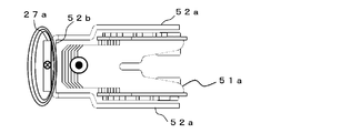
- the core 52 is provided on both sides of the arc extinguishing device 51 so as to cover the support plate 51b, and covers a pair of side plate portions 52a made of a magnetic material and the fixed contact 21 side of the descending electric circuit 27a. And a shield portion 52b provided between the descending electric circuit 27a and the arc runner 27f to shield a magnetic field generated around the arc runner 27f by a current flowing through the descending electric circuit 27a. Further, one set of side plate portions 52a is arranged above both first electric circuit parallel portions 27b1 and 27c1, respectively, and concentrates magnetic flux generated by current flowing through both first electric circuit parallel portions 27b1 and 27c1 to the side plate portions 52a. This has the effect of reducing the magnetic field near the arc runner 27f.
- the insulating member 53 is provided outside a pair of support plates 51b in the arc extinguishing device 51, and a side portion 53a for insulating between the grid plate 51a and the core 52, and a base of the side portion 53a. 11, the first electric circuit cover 53b and the other first electric circuit cover 53c, which cover the first electric circuits 27b and 27c so as not to be exposed on the grid plate 51a side, and the shield 52b of the core 52. And a shield part cover 53d that covers the grid plate 51a so as not to be exposed.
- the side portion 53a is provided so as to cover the entire side surface of the arc extinguishing device 51, including the swaged portion 51a2 of the grid plate 51a protruding from the support plate 51b.
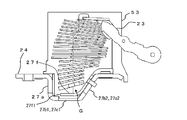
- both the first electric path parallel portions 27b1 and 27c1 and the arc runner 27f are arranged such that the upper end of the descending electric circuit 27a, the connection portion 27d, and the fixed contact 21 are smaller than the base 11. It is provided on the side. This creates a space G surrounded by the descending electric circuit 27a, the first electric circuit parallel portions 27b1, 27c1, and the arc runner 27f, and the first electric circuit ascending portions 27b2, 27c2.
- the lower end can be arranged closer to the base 11 than the upper end of the descending electric circuit 27a.
- the arc extinguishing device 51 can install the grid plate 51a in the created space G, so that the number of grid plates 51a can be increased as a whole. Further, the terminal end 27f1 of the arc runner 27f is provided closer to the base 11 than the fixed contact 21. The separation distance between the arc runner 27f and the movable contact 22 is determined by the distance between the fixed contact 21 and the movable contact 22. It is configured wider than the distance.
- FIGS. 9A and 9B are explanatory diagrams for explaining driving of an arc by a current flowing through a second electric path of a fixed contact.
- FIG. 9A illustrates a case where a current flows from a fixed contact to a movable contact
- FIG. 10 is an explanatory view for explaining the driving of the arc by the arc extinguishing device and the core when the current flows through the fixed contact
- FIG. 11 shows the driving of the arc by the direction of the current flowing through the second electric path of the fixed contact.
- FIGS. 12A and 12B are explanatory diagrams for explaining a case where a current flows from a fixed contact to a movable contact
- FIG. 12A and 12B are explanatory diagrams for explaining a case where a current flows from a fixed contact to a movable contact
- FIG. 12A and 12B are explanatory diagrams for explaining a case where a current flows from a fixed contact to a movable contact
- FIG. 12B shows a case where a current flows from a movable contact to a fixed contact
- FIG. FIG. 13 is an explanatory diagram for explaining a gap between a core and an arc extinguishing device
- FIG. 14 is an explanatory diagram for explaining arc driving when a magnetic saturation occurs in a shield portion. is there.
- the tripping device 40 pushes the trip bar 33, so that the opening / closing mechanism 30 is driven and the crossbar 32 starts rotating.
- the movable contact 23 is also rotated by the rotation of the cross bar 32, and the movable contact 22 provided on the movable contact 23 is separated from the fixed contact 21.
- the rotation of the movable contact 23 advances during the interruption, the arc maintained between the movable contact 22 and the fixed contact 21 after the movable contact 22 reaches the maximum separation distance from the fixed contact 21 is further increased.
- a method of moving to the arc-extinguishing space having a large separation distance will be described.
- the arc when the arc runs on the arc runner 27f, the arc receives an electromagnetic force in the direction of the arrow C which is the direction of the power supply side terminal 24 regardless of the direction of the current, and the arc end 27f1 of the arc runner 27f. Driven up to.
- the arc extinguishing device 51 is called a de-ion arc extinguishing device, and the magnetic flux generated by the arc in the U-shaped notch 51c is, as shown in FIG. Since there is no magnetic material, the magnetic flux becomes dense because the magnetic flux passes through the grid plate 51a and the side plates 52a and 52a of the core 52, and becomes coarse. Due to the bias of the magnetic flux, the arc is driven in the direction of the power supply terminal 24 shown by the arrow E.
- the provision of the pair of side plates 52a of the core 52 increases the magnetic path cross-sectional area, so that the magnetic flux density can be increased.
- the driving force in the direction of E also increases.
- the magnetic flux generated on the arc runner 27f is concentrated on the shield portion 52b by the magnetic field due to the current flowing through the descending electric circuit 27a, and the fixed contact 21 side of the descending electric circuit 27a is A shield portion 52b is provided between the descending electric path 27a and the arc runner 27f so as to cover. Therefore, as shown in FIG. 12, most of the magnetic flux due to the current flowing through the descending electric circuit 27a passes through the shield portion 52b. Therefore, there is almost no magnetic flux passing on the arc runner 27f, and the arc is driven to the end 27f1 of the arc runner 27f.
- the operation of the core 52 when the overcurrent flowing through the electric circuit is very large will be described.
- the overcurrent flowing through the circuit breaker 100 is very large, it is possible that the overcurrent flowing through the descending electric circuit 27a causes the shield portion 52b of the core 52 to cause magnetic saturation. Therefore, by configuring the gap between the arc extinguishing device 51 and the core 52 as described below, even when the shield portion 52b causes magnetic saturation, the arc can be driven to the terminal portion 27f1 of the arc runner 27f. I have to.
- the gap between the arc extinguishing device 51 and the side plate portion 52a of the core 52 is determined by the distance L1 between the caulking portion 51a2 of the grid plate 51a and the side plate portion 52a, and the gap between the shield portion 52b of the grid plate 51a and the core.
- the relationship of the distance L2 between the side plate 52 and the side plate 52a is configured to satisfy L1 ⁇ L2. That is, the interval between the side plate portion 52a and the grid plate 51a is configured such that the interval L1 on the movable contact 23 side is smaller than the interval L2 on the descending electric path 27a side. Due to the relationship of this interval L1 ⁇ interval L2, the magnetic resistance of the path passing through the caulking portion 51a2 is reduced.
- the magnetic flux due to the descending electric path 27a does not concentrate near the shield portion 52b, and the magnetic flux also flows to the caulking portion 51a2 of the grid plate 51a. Can be dispersed.
- the electromagnetic force for driving the arc in the direction of the fixed contact 21 is also reduced. Therefore, the electromagnetic force for driving the arc in the direction of the power supply terminal 24 by the current flowing through the arc runner 27f is reduced. As a result, the arc is driven to the end 27f1. Further, after the arc moves toward the power supply terminal 24, the magnetic flux passing through the caulking portion 51a2 generates an electromagnetic force that drives the arc toward the power supply terminal 24. Will be further promoted.
- the descending electric path 27a descending from the power supply terminal 24 toward the bottom surface of the base 11, the first electric paths 27b, 27c, and the first electric paths 27b, 27c extending from the descending electric path 27a toward the movable contact 23.
- a second electric circuit 27e extending from the second electric circuit 24 to the power supply terminal 24 and provided with the fixed contact 21; an arc runner extending from the end of the second electric circuit 27e toward the power supply terminal 24 and the bottom surface of the base 11; A movable contact 23 provided with a movable contact 22 having a center of rotation provided on the base 11 and being brought into contact with and separated from the fixed contact 21 by the rotation; a descending electric path 27a;
- the shield portion 52b is provided between the arc runners 27f and shields a magnetic field due to a current flowing through the descending electric path 27a, so that many grid plates 51a can be arranged, and Away distance becomes possible to drive the arc interruption until wide arc runner 27f, it is possible to cut off the high voltage path without depending on the distance between the contacts 21 and 22.
- a U-shaped notch 51c on the movable contact 23 side and side feet 51a1 are formed on both sides of the notch 51c, and the notch 51c surrounds both the contacts 21, 22 and the fixed contact 27.
- An arc extinguishing device 51 composed of a plate 51a, and a side plate portion 52a made of a magnetic material and provided on both sides of the arc extinguishing device 51 so as to cover the side surface of the arc extinguishing device 51, and the shield portion 52b is provided with an arc extinguishing device. Since the two side plate portions 52a provided on both sides of 51 are connected, assemblability can be improved.
- the grid plate 51a Since it can be installed on the base 11 side and the number of grid plates 51a can be increased, the blocking performance can be improved.
- the interval between the side plate portion 52a and the grid plate 51a is configured such that the interval L1 on the movable contact 23 side is smaller than the interval L2 on the descending electric path side, when the shield portion 52b causes magnetic saturation, The magnetic flux generated by the descending electric path 27a can be dispersed to the caulking portion 51a2 side of the grid plate 51a without being concentrated near the shield portion 52b.
- the electromagnetic force for driving the arc in the direction of the fixed contact 21 is reduced, and the electromagnetic force for driving the arc in the direction of the power supply side terminal 24 is enhanced by the current flowing through the arc runner 27f. Can be driven in the direction of.
- the first electric paths 27b and 27c extend from the descending electric path 27a on the base 11 in parallel with the base 11, and the first electric paths parallel to the base 11, and the first electric paths 27b1 and 27c1 ascending from the first electric path parallel parts 27b1 and 27c1 toward the fixed contact 21. Since there are provided the first electric circuit rising portions 27b2, 27c2 and the first electric circuit connecting portions 27b3, 27c3 extending from the first electric circuit rising portions 27b2, 27c2 to the connecting portion 27d, a large number of grid plates 51a can be arranged and the separation distance can be reduced. The arc can be driven and interrupted up to the wide arc runner 27f, and the high-voltage electric circuit can be interrupted regardless of the distance between the two contacts 21 and 22.
- the arc runner 27f is provided on the cover 12 side from the upper surface of the first electric circuit parallel portions 27b1 and 27c1, the magnetic flux caused by the current flowing from the second electric circuit 27e to the arc runner 27f is directed toward the arc toward the terminal end 27f1. A driving force can be generated.
- the side plate portions 52a, 52a of the core 52 are arranged above the one first electric circuit parallel portion 27b1 and the other first electric circuit parallel portion 27c1, and are formed by the current flowing through both the first electric circuit parallel portions 27b1, 27c1. Since it has a function of concentrating the magnetic flux and shielding the magnetic field, the magnetic flux generated by the current flowing through the first parallel electric circuit portions 27b1 and 27c1 inhibits the driving of the arc by the magnetic flux generated by the current flowing from the second electric circuit 27e to the arc runner 27f. Can be prevented.
- the shield portion 52b is provided on the arc runner 27f side of the descending electric circuit 27a, and the magnetic flux generated by the current flowing through the descending electric circuit 27a concentrates on the shield portion 52b and the magnetic field is shielded, so that it flows through the descending electric circuit 27a. It is possible to prevent the arc at the time of interruption from being repelled and driven in the direction of the fixed contact 21 by the magnetic flux due to the current, thereby improving the interruption performance.
- the magnetic flux passing through the caulking portion 51a2 generates an electromagnetic force for driving the arc in the direction of the power supply side terminal 24, and the terminal portion 27f1 of the arc runner 27f of the arc. Can be further promoted.
- FIG. FIG. 15 is a side sectional view showing the entire circuit breaker according to Embodiment 2 of the present invention
- FIG. 16 is a diagram showing an arc extinguishing unit including a fixed contactor of the circuit breaker according to Embodiment 2 of the present invention. It is an exploded perspective view shown.
- the circuit breaker 101 of the present embodiment is different from the first embodiment in that the side plate portion 52a of the core 52 provided in the first embodiment is eliminated and only the shield portion 52c is provided.
- components having the same functions as in the first embodiment are denoted by the same reference numerals, and description thereof will be omitted. The following description focuses on differences from the circuit breaker 100 of the first embodiment.
- the arc extinguishing unit 50 may be provided with only a shield portion 52c between the descending electric path 27a and the arc runner 27f for shielding a magnetic field due to a current flowing through the descending electric path 27a.
- the core 52 in the first embodiment has a side plate portion 52a and has a complicated shape. Therefore, it is preferable that the core 52 be made of a magnetic material such as an iron plate having a small thickness.
- the shield portion 52c of the present embodiment has a small shape. Since a plate-shaped rectangular parallelepiped, if a thick iron plate or a magnetic steel plate having a large saturation magnetic flux density and a large cross-sectional area is used, magnetic saturation at an excessive current can be prevented. The effect of not being provided can be reduced.
- the descending electric path 27a descending from the power supply terminal 24 toward the bottom surface of the base 11, the first electric paths 27b, 27c, and the first electric paths 27b, 27c extending from the descending electric path 27a toward the movable contact 23.
- a second electric circuit 27e extending from the second electric circuit 24 to the power supply terminal 24 and provided with the fixed contact 21; an arc runner extending from the end of the second electric circuit 27e toward the power supply terminal 24 and the bottom surface of the base 11; A movable contact 23 provided with a movable contact 22 having a center of rotation provided on the base 11 and being brought into contact with and separated from the fixed contact 21 by the rotation; a descending electric path 27a; Since the shield portion 52c is provided between the arc runners 27f and shields a magnetic field due to a current flowing through the descending electric path 27a, a large number of grid plates 51a can be arranged, and Away distance becomes possible to drive the arc interruption until wide arc runner 27f, it is possible to cut off the high voltage path without depending on the distance between the contacts 21 and 22.
- the first electric paths 27b and 27c extend from the descending electric path 27a on the base 11 in parallel with the base 11, and the first electric paths parallel to the base 11, and the first electric paths 27b1 and 27c1 ascending from the first electric path parallel parts 27b1 and 27c1 toward the fixed contact 21. Since there are provided the first electric circuit rising portions 27b2 and 27c2 and the first electric circuit connecting portions 27b3 and 27c3 extending from the first electric circuit rising portions 27b2 and 27c2 to the connecting portion 27d, a large number of grid plates 51a can be arranged and the separation distance can be reduced. The arc can be driven and interrupted up to the wide arc runner 27f, and the high-voltage electric circuit can be interrupted regardless of the distance between the two contacts 21 and 22.
- the connecting portion 27d and the fixed contact 21, the grid plate 51a is connected to the descending circuit 27a.
- the arc runner 27f is provided on the cover 12 side from the upper surface of both the first electric path parallel portions 27b1 and 27c1, the magnetic flux due to the current flowing from the second electric path 27e to the arc runner 27f effectively works for driving the arc. be able to.
- the shield portion 52c is provided on the arc runner 27f side of the descending electric circuit 27a, and the magnetic flux generated by the current flowing through the descending electric circuit 27a concentrates on the shield portion 52c and the magnetic field is shielded, so that it flows through the descending electric circuit 27a. It is possible to prevent the arc at the time of interruption from being repelled and driven in the direction of the fixed contact 21 by the magnetic flux due to the current, thereby improving the interruption performance.
Landscapes
- Arc-Extinguishing Devices That Are Switches (AREA)
- Breakers (AREA)
Abstract
回路遮断器100は、ベース11上に設けられた電源側端子24と、電源側端子24からベース11の底面方向に下降する下降電路27a、下降電路27aから可動接触子23方向に伸びる第1電路27b、27c、第1電路27b、27cから電源側端子24の方向に延設され固定接点21が設けられた第2電路27e、第2電路27eの端部から電源側端子24の方向に延びるアークランナー27f、を有する固定接触子27と、固定接点21と接触および開離する可動接点22が設けられた可動接触子23と、切り欠き部51a1が両接点21、22を囲む複数のグリッド板51aからなる消弧装置51と、下降電路27aとアークランナー27fの間に設けられ、下降電路27aを流れる電流による磁界を遮蔽するシールド部52bと、を備えた。
Description
この発明は、電圧が高い電路を遮断するための回路遮断器に関し、特に内蔵されている消弧装置と固定接触子に関するものである。
直流電路の普及に伴い、電路を高電圧化して銅損を削減したいというニーズが高まっており、直流電路で使用される回路遮断器にも高電圧化の要求が増してきている。電圧が高い電路を遮断するためには、開閉接点の開離距離を大きくすることが有効であるが、開閉接点の開離距離を大きくするためには、回路遮断器のすべてを新しく設計しなければならない。
そのため、開閉接点の開離距離を変更することなく、高電圧の電路を遮断する方法として、可動接触子の回動中心が操作ハンドル側にあるタイプの回路遮断器では、負荷側端子の電位を導くアークランナーと、電源側端子の電位を導くアークランナーを消弧装置の上下に設け、アークを開離距離の広い場所まで走行させて遮断する方法が知られている(例えば、特許文献1参照)。
そのため、開閉接点の開離距離を変更することなく、高電圧の電路を遮断する方法として、可動接触子の回動中心が操作ハンドル側にあるタイプの回路遮断器では、負荷側端子の電位を導くアークランナーと、電源側端子の電位を導くアークランナーを消弧装置の上下に設け、アークを開離距離の広い場所まで走行させて遮断する方法が知られている(例えば、特許文献1参照)。
ベース底面側に可動接触子の回動中心があるタイプの従来の回路遮断器では、消弧装置が電源側端子の側に設けられ、固定接点がベース底面側に設けられることが一般的なため、電源側端子から固定接点までの電路が消弧装置とベースの間を通ることとなる。そうすると、電源側端子の電位は消弧装置の下側となるので、負荷側端子の電位を消弧装置の上部まで導くことが必要となる。
しかし、開閉機構部が設けられる極では、開閉機構部があるため負荷側端子の電位を消弧装置の上部まで導くことが非常に難しいという問題があった。
しかし、開閉機構部が設けられる極では、開閉機構部があるため負荷側端子の電位を消弧装置の上部まで導くことが非常に難しいという問題があった。
この発明はかかる問題を解決するためになされたもので、従来のベース底面側に可動接触子の回動中心があるタイプの回路遮断器において、開閉接点間の距離を変更することなく、電路の高電圧化に対応することができる回路遮断器の提供を目的とするものである。
本発明の回路遮断器は、ベース上に設けられた電源側端子と、電源側端子からベースの底面方向に下降する下降電路、下降電路から可動接触子の方向に伸びる第1電路、第1電路から電源側端子の方向に延設され固定接点が設けられた第2電路、第2電路の端部から電源側端子の方向に延びるアークランナー、を有する固定接触子と、下降電路とアークランナーの間に設けられ、下降電路を流れる電流による磁界を遮蔽するシールド部と、を備えたものである。
この発明に係る回路遮断器によれば、開閉接点間の開離距離を拡大することなく、電路の高電圧化に対応することができる。
実施の形態1.
図1は本発明の実施の形態1における回路遮断器の全体を示す側断面図、図2は図1の回路遮断器における消弧装置、固定接触子側電路を含む消弧ユニットを示す分解斜視図、図3は図2の消弧ユニットが組み立てられた状態を示す斜視図、図4は図3の消弧ユニットにおける可動子ストッパーを外した状態の消弧装置を示す分解斜視図、図5は図3の消弧ユニットにおける固定接触子を示す図で、(a)は上面図、(b)は側面図、図6は図3の消弧ユニットにおけるコアを示す図で、(a)は上面図、(b)は側面図、図7は図3の消弧ユニットにおける絶縁部材を示す図で、(a)は上面図、(b)は側面図、(c)は斜視図、図8は消弧ユニットの側面を示す図で、グリッド板の枚数の増加設置を説明するための説明図である。
図1は本発明の実施の形態1における回路遮断器の全体を示す側断面図、図2は図1の回路遮断器における消弧装置、固定接触子側電路を含む消弧ユニットを示す分解斜視図、図3は図2の消弧ユニットが組み立てられた状態を示す斜視図、図4は図3の消弧ユニットにおける可動子ストッパーを外した状態の消弧装置を示す分解斜視図、図5は図3の消弧ユニットにおける固定接触子を示す図で、(a)は上面図、(b)は側面図、図6は図3の消弧ユニットにおけるコアを示す図で、(a)は上面図、(b)は側面図、図7は図3の消弧ユニットにおける絶縁部材を示す図で、(a)は上面図、(b)は側面図、(c)は斜視図、図8は消弧ユニットの側面を示す図で、グリッド板の枚数の増加設置を説明するための説明図である。
図1に示すように、回路遮断器100は、絶縁材料で形成されたベース11とカバー12とからなる筐体10を用いて構成される。ベース11上には、極数分の回路遮断ユニット20が互いに間隔をおいて配列され、回路遮断ユニット20の上部には、周知のトグルリンク機構を有する開閉機構部30が配置される。カバー12はベース11上の各極の回路遮断ユニット20と開閉機構部30を覆い、開閉機構部30の操作ハンドル31はカバー12のハンドル用窓孔12aから突出している。
各極の回路遮断ユニット20は互いに同じに構成され、クロスバー32は、各極の回路遮断ユニット20に共通して各極の回路遮断ユニット20に直交するように、ベース11上に配置される。このクロスバー32は、開閉機構部30により、その軸心を中心として回動され、各極の回路遮断ユニット20における各可動接触子23がそれぞれ取り付けられる。クロスバー32がその軸心を中心として回動したときに、各極の回路遮断ユニット20の各可動接触子23が同時に回動され、この可動接触子23の回動により、可動接点22が固定接点21に接触および開離する。開閉機構部30は、周知のトグルリンク機構からなり引き外し装置40により駆動される周知のトリップバー33を備えている。
また、各極の回路遮断ユニット20は、ベース11上に設けられた電源側端子24と、電源側端子24から延設され、固定接点21が設けられる固定接触子27と、この固定接点21と接触および開離する可動接点22と、この可動接点22が一端に設けられ、クロスバー32により回動自由に保持されている可動接触子23と、この可動接触子23に可動接触子ホルダー26を介して接続された引き外し装置40と、引き外し装置40より延設された負荷側端子25と、固定接触子27と組み合わさり遮断時のアークを消弧する消弧ユニット50と、を有する。
なお、請求の範囲で述べている「第1外部端子」は電源側端子24および負荷側端子25のいずれか一方であり、「第2外部端子」は、電源側端子24および負荷側端子25のいずれか他方である。
なお、請求の範囲で述べている「第1外部端子」は電源側端子24および負荷側端子25のいずれか一方であり、「第2外部端子」は、電源側端子24および負荷側端子25のいずれか他方である。
固定接点21と可動接点22とで、電路を開閉する開閉接点を構成する。可動接点22が固定接点21に接触すれば、両端子24、25の間の電気回路がオンとなり、また、可動接点22が固定接点21から開離すれば、両端子24、25間の電気回路がオフとなる。このとき可動接点22と固定接点21間に生ずるアークは消弧ユニット50により消弧される。
固定接触子27と組み合わされた消弧ユニット50について、図2、図3により説明する。
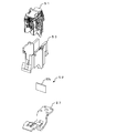
消弧ユニット50は、遮断時に両接点21、22間に発生したアークを消弧する消弧装置51と、消弧装置51の下部に設けられる固定接触子27と、消弧装置51の外側に設けられたコア52と、消弧装置51を囲むように設けられ、消弧装置51とコア52間を絶縁する絶縁部材53と、から構成されている。
消弧ユニット50は、遮断時に両接点21、22間に発生したアークを消弧する消弧装置51と、消弧装置51の下部に設けられる固定接触子27と、消弧装置51の外側に設けられたコア52と、消弧装置51を囲むように設けられ、消弧装置51とコア52間を絶縁する絶縁部材53と、から構成されている。
消弧装置51は、図4に示すように、周知の四角状の板の一辺に略U字形の切り欠き51cを設けた形状で磁性鋼板からなる複数のグリッド板51aと、絶縁性の材料からなり所定の間隔を持って複数のグリッド板51aを支持する1組の支持板51bと、を有している。また、グリッド板51aには切り欠き51cの両側に側足部51a1が形成されており、U字形の切り欠き51cは固定接点21および可動接点22の方向に向くように設置され、このU字形の切り欠き51cにより形成される空間を可動接触子23が回動する。グリッド板51aは、支持板51bを貫通させた先端のカシメ部51a2を拡げるように塑性変形させることで支持板51bに保持されている。ここでは、可動子ストッパー51eは、支持板51bから取り外した状態で示されている。
固定接触子27は、図5に示すように、外部配線が接続される電源側端子24から延設され、ベース11の底面方向にベース11まで伸びる下降電路27aと、下降電路27aから2股に分かれ、可動接触子23方向に伸びる一方の第1電路27bおよび他方の第1電路27cと、両第1電路27b、27cが接続される接続部27dと、固定接点21が設けられ、接続部27dから電源側端子24方向に延設される第2電路27eと、第2電路27eの端部からベース11の底面方向にベース11まで延設された後、電源側端子24方向かつベース11の底面方向に延設されたアークランナー27fと、から構成されている。
ここで、第2電路27eおよびアークランナー27fは、下降電路27aから2股に分かれた一方の第1電路27bおよび他方の第1電路27cの間の空間部27gに設けられている。
両第1電路27b、27cは、下降電路27aからベース11上をベース11に平行に伸びる一方の第1電路平行部27b1および他方の第1電路平行部27c1と、両第1電路平行部27b1、27c1から固定接点21の方向に上昇する一方の第1電路上昇部27b2および他方の第1電路上昇部27c2と、両第1電路上昇部27b2、27c2から接続部27dまで伸びる一方の第1電路接続部27b3および他方の第1電路接続部27c3と、から構成される。
また、アークランナー27fは、両第1電路平行部27b1、27c1の上面よりカバー12側に設けられている。
両第1電路27b、27cは、下降電路27aからベース11上をベース11に平行に伸びる一方の第1電路平行部27b1および他方の第1電路平行部27c1と、両第1電路平行部27b1、27c1から固定接点21の方向に上昇する一方の第1電路上昇部27b2および他方の第1電路上昇部27c2と、両第1電路上昇部27b2、27c2から接続部27dまで伸びる一方の第1電路接続部27b3および他方の第1電路接続部27c3と、から構成される。
また、アークランナー27fは、両第1電路平行部27b1、27c1の上面よりカバー12側に設けられている。
コア52は、図6に示すように、消弧装置51の両側に支持板51bを覆うように設けられ、磁性体からなる1組の側板部52aと、下降電路27aの固定接点21側を覆うように下降電路27aとアークランナー27fの間に設けられ、下降電路27aを流れる電流によって、アークランナー27f周辺に発生する磁界を遮蔽するシールド部52bと、を有している。
また、1組の側板部52aは、それぞれ両第1電路平行部27b1、27c1の上部に配置されており、両第1電路平行部27b1、27c1に流れる電流によって発生する磁束を側板部52aに集中させ、アークランナー27f付近の磁界を低減する作用を有している。
また、1組の側板部52aは、それぞれ両第1電路平行部27b1、27c1の上部に配置されており、両第1電路平行部27b1、27c1に流れる電流によって発生する磁束を側板部52aに集中させ、アークランナー27f付近の磁界を低減する作用を有している。
絶縁部材53は、図7に示すように、消弧装置51における1組の支持板51bの外側に設けられ、グリッド板51aとコア52間の絶縁を行う側部53aと、側部53aのベース11側に設けられ、両第1電路27b、27cがグリッド板51a側に露出しないように覆う一方の第1電路カバー部53bおよび他方の第1電路カバー部53cと、コア52のシールド部52bがグリッド板51a側に露出しないように覆うシールド部カバー53dと、を有している。なお、側部53aは、支持板51bから突き出たグリッド板51aのカシメ部51a2も含め、消弧装置51の側面全体を覆うように設けられている。
以上説明した通り消弧ユニット50は、図8に示すように、両第1電路平行部27b1、27c1、およびアークランナー27fが、下降電路27aの上端、接続部27dおよび固定接点21よりもベース11側に設けられている。これにより、下降電路27aと、両第1電路平行部27b1、27c1およびアークランナー27fと、両第1電路上昇部27b2、27c2とで囲まれた空間Gを創出することで、消弧装置51の下端を下降電路27aの上端よりベース11側に配置可能となっている。
そして、このような構成により、消弧装置51は創出された空間Gにグリッド板51aを設置できるので、全体としてグリッド板51aの枚数を増設することが可能となっている。
また、アークランナー27fの終端部27f1は、固定接点21よりもベース11側に設けられており、アークランナー27fと可動接点22間の開離距離は、固定接点21と可動接点22間の開離距離よりも広く構成されている。
また、アークランナー27fの終端部27f1は、固定接点21よりもベース11側に設けられており、アークランナー27fと可動接点22間の開離距離は、固定接点21と可動接点22間の開離距離よりも広く構成されている。
次に回路遮断器100の投入と遮断動作を説明する。
操作ハンドル31を投入すると周知のトグルリンクの開閉機構部30がデッドポイントを超えることで、クロスバー32が回転を始める。クロスバー32が回転することで可動接触子23が回動し、可動接触子23に設けられた可動接点22が固定接点21に接触し、回路遮断器100はON状態となる。
操作ハンドル31を投入すると周知のトグルリンクの開閉機構部30がデッドポイントを超えることで、クロスバー32が回転を始める。クロスバー32が回転することで可動接触子23が回動し、可動接触子23に設けられた可動接点22が固定接点21に接触し、回路遮断器100はON状態となる。
次に遮断動作について説明する。
図9は固定接触子の第2電路に流れる電流によるアークの駆動を説明するための説明図で、(a)は固定接点から可動接点に電流が流れている場合、(b)は可動接点から固定接点に電流が流れている場合、図10は消弧装置とコアによるアークの駆動を説明するための説明図、図11は固定接触子の第2電路に流れる電流の向きによるアークの駆動を説明するための説明図で、(a)は固定接点から可動接点に電流が流れている場合、(b)は可動接点から固定接点に電流が流れている場合、図12はシールド部の作用を説明するための説明図、図13はコアと消弧装置の間のギャップを説明するための説明図、図14はシールド部が磁気飽和を起こした時のアーク駆動を説明するための説明図である。
図9は固定接触子の第2電路に流れる電流によるアークの駆動を説明するための説明図で、(a)は固定接点から可動接点に電流が流れている場合、(b)は可動接点から固定接点に電流が流れている場合、図10は消弧装置とコアによるアークの駆動を説明するための説明図、図11は固定接触子の第2電路に流れる電流の向きによるアークの駆動を説明するための説明図で、(a)は固定接点から可動接点に電流が流れている場合、(b)は可動接点から固定接点に電流が流れている場合、図12はシールド部の作用を説明するための説明図、図13はコアと消弧装置の間のギャップを説明するための説明図、図14はシールド部が磁気飽和を起こした時のアーク駆動を説明するための説明図である。
電路に過電流が流れると、引き外し装置40がトリップバー33を押すので、開閉機構部30が駆動され、クロスバー32が回動を開始する。クロスバー32の回動により可動接触子23も回動し、可動接触子23に設けられた可動接点22が固定接点21から開離する。
次に、遮断時に可動接触子23の回動が進み、可動接点22が固定接点21に対して最大の開離距離となった後、可動接点22と固定接点21間で維持されるアークをより開離距離の大きい消弧空間へ移動させる方法について説明する。
次に、遮断時に可動接触子23の回動が進み、可動接点22が固定接点21に対して最大の開離距離となった後、可動接点22と固定接点21間で維持されるアークをより開離距離の大きい消弧空間へ移動させる方法について説明する。
まず、第2電路27e、アークランナー27fの作用について説明する。
図9(a)に示すように、電流が、矢印A1で示す電源側端子24から固定接点21の方向、すなわち、固定接点21から可動接点22に流れている場合、第2電路27eを流れる電流は、可動接触子23の回動中心から電源側端子24の方向に流れている。よって、第2電路27eを流れる電流により発生する第2電路27eにおけるカバー12側の磁束は、図9(a)の紙面上で上向きの矢印B1の方向となる。この磁束によりアークは、電源側端子24方向である矢印Cの向きに電磁力を受けることとなる。
図9(a)に示すように、電流が、矢印A1で示す電源側端子24から固定接点21の方向、すなわち、固定接点21から可動接点22に流れている場合、第2電路27eを流れる電流は、可動接触子23の回動中心から電源側端子24の方向に流れている。よって、第2電路27eを流れる電流により発生する第2電路27eにおけるカバー12側の磁束は、図9(a)の紙面上で上向きの矢印B1の方向となる。この磁束によりアークは、電源側端子24方向である矢印Cの向きに電磁力を受けることとなる。
逆に、図9(b)に示すように、電流が、矢印A2で示す固定接点21から電源側端子24の方向、すなわち、可動接点22から固定接点21に流れている場合、第2電路27eを流れる電流は、電源側端子24から可動接触子23の回動中心の方向に流れている。よって、第2電路27eを流れる電流により発生する第2電路27eにおけるカバー12側の磁束は、図9(b)の紙面上で下向きの矢印B2の方向となる。この磁束によりアークは、電源側端子24方向である矢印Cの向きに電磁力を受けることとなる。
また、アークランナー27f上にアークが走行した場合にも同様に、アークは、電流の向きによらず電源側端子24方向である矢印Cの向きに電磁力を受け、アークランナー27fの終端部27f1まで駆動される。
また、アークランナー27f上にアークが走行した場合にも同様に、アークは、電流の向きによらず電源側端子24方向である矢印Cの向きに電磁力を受け、アークランナー27fの終端部27f1まで駆動される。
次に、消弧装置51とコア52によるアークの駆動について説明する。
消弧装置51はディアイオン消弧装置と呼ばれるもので、U字形の切り欠き51cにあるアークによって発生する磁束は、図10に示すように、可動接触子23の回動中心側の磁束D1は、磁性体がないため密となり、電源側端子24側の磁束D2は、グリッド板51aおよびコア52の側板部52a、52aを磁束が通るため粗となる。この磁束の偏りにより、アークは、矢印Eで示す電源側端子24方向に駆動される。
この時、消弧装置51だけの場合に比して、コア52の1組の側板部52aを設けることで、磁路断面積が大きくなるため、磁束密度を大きくすることができ、アークを矢印Eの方向に駆動する力も大きくなる。
消弧装置51はディアイオン消弧装置と呼ばれるもので、U字形の切り欠き51cにあるアークによって発生する磁束は、図10に示すように、可動接触子23の回動中心側の磁束D1は、磁性体がないため密となり、電源側端子24側の磁束D2は、グリッド板51aおよびコア52の側板部52a、52aを磁束が通るため粗となる。この磁束の偏りにより、アークは、矢印Eで示す電源側端子24方向に駆動される。
この時、消弧装置51だけの場合に比して、コア52の1組の側板部52aを設けることで、磁路断面積が大きくなるため、磁束密度を大きくすることができ、アークを矢印Eの方向に駆動する力も大きくなる。
さらに、アークが、アークランナー27f上を電源側端子24方向に駆動され、下降電路27aに近づいた時、下降電路27aを流れる電流により発生する磁界が、アークに影響を与えるようになるので、まず、シールド部52bがない場合について説明する。
図11(a)に示すように、固定接点21から可動接点22の方向に電流が流れている場合、下降電路27aを流れる電流による磁束は、図11(a)の紙面上で時計回転の方向となり、電源側端子24方向に駆動されたアークを矢印Fで示す固定接点21方向に駆動する電磁力を発生させる。
同様に、可動接点22から固定接点21の方向に電流が流れている場合にも、図11(b)に示すように、下降電路27aを流れる電流にする磁束は、図11(b)の紙面上で反時計回転の方向となり、電源側端子24方向に駆動されたアークを矢印Fで示す固定接点21方向に駆動する電磁力を発生させる。
同様に、可動接点22から固定接点21の方向に電流が流れている場合にも、図11(b)に示すように、下降電路27aを流れる電流にする磁束は、図11(b)の紙面上で反時計回転の方向となり、電源側端子24方向に駆動されたアークを矢印Fで示す固定接点21方向に駆動する電磁力を発生させる。
一方、本実施の形態の回路遮断器100では、下降電路27aを流れる電流による磁界によって、アークランナー27f上に発生する磁束をシールド部52bに集中させるように、下降電路27aの固定接点21側を覆うように、下降電路27aとアークランナー27fの間にシールド部52bを設けている。
このため、図12に示すように、下降電路27aを流れる電流による磁束のほとんどは、シールド部52bを通ることとなる。このため、アークランナー27f上を通る磁束はほとんど存在せず、アークは、アークランナー27fの終端部27f1まで駆動されることとなる。
このため、図12に示すように、下降電路27aを流れる電流による磁束のほとんどは、シールド部52bを通ることとなる。このため、アークランナー27f上を通る磁束はほとんど存在せず、アークは、アークランナー27fの終端部27f1まで駆動されることとなる。
次に、電路を流れる過電流が非常に大きい場合におけるコア52の作用について説明する。
回路遮断器100に流れる過電流が非常に大きい場合、下降電路27aを流れる過大電流によってコア52のシールド部52bが磁気飽和を起こしてしまう可能性が考えられる。そのため、消弧装置51とコア52とのギャップを以下に説明するように構成することでシールド部52bが磁気飽和を起こした場合にも、アークがアークランナー27fの終端部27f1まで駆動されるようにしている。
回路遮断器100に流れる過電流が非常に大きい場合、下降電路27aを流れる過大電流によってコア52のシールド部52bが磁気飽和を起こしてしまう可能性が考えられる。そのため、消弧装置51とコア52とのギャップを以下に説明するように構成することでシールド部52bが磁気飽和を起こした場合にも、アークがアークランナー27fの終端部27f1まで駆動されるようにしている。
図13に示すように、消弧装置51とコア52の側板部52aとのギャップは、グリッド板51aのカシメ部51a2と側板部52aとの間隔L1と、グリッド板51aのシールド部52b側とコア52の側板部52aとの間隔L2の関係が、L1<L2となるように構成されている。すなわち、側板部52aとグリッド板51aとの間隔は、可動接触子23側の間隔L1が、下降電路27a側の間隔L2より小さく構成されている。この間隔L1<間隔L2の関係により、カシメ部51a2を経由する経路の磁気抵抗を下げるようにしている。
これにより、図14に示すように、シールド部52bが磁気飽和を起こした場合には、下降電路27aによる磁束はシールド部52bの近くに集中せず、グリッド板51aのカシメ部51a2側にも磁束を分散させることができる。下降電路27aによる磁束を分散させることで、アークを固定接点21の方向への駆動する電磁力も低減されるので、アークランナー27fを流れる電流によってアークを電源側端子24の方向へ駆動する電磁力が勝ることとなり、アークは終端部27f1まで駆動される。
また、アークが電源側端子24の方へ移動した後、カシメ部51a2側を通る磁束は、アークを電源側端子24の方向へ駆動する電磁力を発生させるので、アークの終端部27f1への駆動がより促進されることとなる。
また、アークが電源側端子24の方へ移動した後、カシメ部51a2側を通る磁束は、アークを電源側端子24の方向へ駆動する電磁力を発生させるので、アークの終端部27f1への駆動がより促進されることとなる。
本実施の形態によれば、電源側端子24からベース11の底面方向に下降する下降電路27a、下降電路27aから可動接触子23の方向に伸びる第1電路27b、27c、第1電路27b、27cから電源側端子24の方向に延設され固定接点21が設けられた第2電路27e、第2電路27eの端部から電源側端子24の方向かつベース11の底面方向に延設されたアークランナー27fを有する固定接触子27と、回動の中心がベース11上に設けられ、回動により固定接点21と接触および開離する可動接点22が設けられた可動接触子23と、下降電路27aとアークランナー27fの間に設けられ、下降電路27aを流れる電流による磁界を遮蔽するシールド部52bとを備えたので、グリッド板51aを多く配置でき、かつ開離距離が広いアークランナー27fまでアークを駆動し遮断が可能となり、両接点21、22間の距離に依存せず高電圧の電路を遮断することができる。
また、可動接触子23側にU字形の切り欠き部51cおよび切り欠き部51cの両側に側足部51a1が形成され切り欠き部51cが両接点21、22及び固定接触子27を囲む複数のグリッド板51aからなる消弧装置51と、磁性体からなり、消弧装置51の両側に消弧装置51の側面を覆うように設けられた側板部52aとを備え、シールド部52bは、消弧装置51の両側に設けられた2枚の側板部52aを連結しているので、組み立て性を向上することができる。
両第1電路平行部27b1、27c1、およびアークランナー27fは、下降電路27aの上端、接続部27dおよび固定接点21よりもベース11側に設けられているので、グリッド板51aを下降電路27aの上端よりベース11側に設置可能となり、グリッド板51aの枚数を増やすことができるので、遮断性能を向上することができる。
両第1電路平行部27b1、27c1、およびアークランナー27fは、下降電路27aの上端、接続部27dおよび固定接点21よりもベース11側に設けられているので、グリッド板51aを下降電路27aの上端よりベース11側に設置可能となり、グリッド板51aの枚数を増やすことができるので、遮断性能を向上することができる。
また、側板部52aとグリッド板51aとの間隔は、可動接触子23側の間隔L1が下降電路側の間隔L2より小さく構成されているので、シールド部52bが磁気飽和を起こした場合には、下降電路27aによる磁束を、シールド部52bの近くに集中せず、グリッド板51aのカシメ部51a2側にも分散させることができる。これにより、アークを固定接点21の方向への駆動する電磁力が低減されるので、アークランナー27fを流れる電流によってアークを電源側端子24の方向へ駆動する電磁力が勝ることとなり、終端部27f1の方向にアークを駆動することができる。
第1電路27b、27cと第2電路27eとを接続する接続部27dを備え、第1電路27b、27cは、下降電路27aから接続部27dまで中央に空間部27gを有して2分割されており、第2電路27eおよびアークランナー27fは、第1電路27b、27cの空間部27gに設けられているので、第2電路27eおよびアークランナー27fを流れる電流による磁界は、終端部27f1の方向にアークを駆動する力を発生させることができる。
第1電路27b、27cは、下降電路27aからベース11上をベース11に平行に伸びる第1電路平行部27b1、27c1と、第1電路平行部27b1、27c1から固定接点21の方向に上昇する第1電路上昇部27b2、27c2と、第1電路上昇部27b2、27c2から接続部27dまで伸びる第1電路接続部27b3、27c3とを備えたので、グリッド板51aを多く配置でき、かつ開離距離が広いアークランナー27fまでアークを駆動し遮断が可能となり、両接点21、22間の距離に依存せず高電圧の電路を遮断することができる。
また、アークランナー27fは両第1電路平行部27b1、27c1の上面よりカバー12側に設けられているので、第2電路27eからアークランナー27fに流れる電流による磁束は、アークを終端部27f1の方向に駆動する力を発生させることができる。
また、コア52の側板部52a、52aは、一方の第1電路平行部27b1、他方の第1電路平行部27c1の上部に配置されており、両第1電路平行部27b1、27c1に流れる電流による磁束を集中させ磁界を遮蔽する作用を有するので、両第1電路平行部27b1、27c1に流れる電流による磁束が、第2電路27eからアークランナー27fに流れる電流発生する磁束によるアークの駆動を阻害することを防止することができる。
また、シールド部52bは、下降電路27aのアークランナー27f側に設けられており、下降電路27aを流れる電流によって発生する磁束がシールド部52bに集中し磁界が遮蔽されるので、下降電路27aを流れる電流による磁束により遮断時のアークが固定接点21方向に反発駆動されることを防止し遮断性能を向上することができる。
また、アークが電源側端子24の方へ通過した後、カシメ部51a2側を通る磁束は、アークを電源側端子24の方向へ駆動する電磁力を発生させ、アークのアークランナー27fの終端部27f1の方向への駆動をより促進することができる。
実施の形態2.
図15は本発明の実施の形態2における回路遮断器の全体を示す側断面図、図16は本発明の実施の形態2における回路遮断器の消弧装置、固定接触子を含む消弧ユニットを示す分解斜視図である。
本実施の形態の回路遮断器101は、図15に示すように、実施の形態1において、設けていたコア52の側板部52aを廃止し、シールド部52cだけとしたものである。以下においては、実施の形態1と同様の機能を有する構成要素については同一符号を付して説明を省略し、実施の形態1の回路遮断器100と異なる点を中心に説明する。
図15は本発明の実施の形態2における回路遮断器の全体を示す側断面図、図16は本発明の実施の形態2における回路遮断器の消弧装置、固定接触子を含む消弧ユニットを示す分解斜視図である。
本実施の形態の回路遮断器101は、図15に示すように、実施の形態1において、設けていたコア52の側板部52aを廃止し、シールド部52cだけとしたものである。以下においては、実施の形態1と同様の機能を有する構成要素については同一符号を付して説明を省略し、実施の形態1の回路遮断器100と異なる点を中心に説明する。
消弧ユニット50は、図16に示すように、下降電路27aとアークランナー27fの間に、下降電路27aを流れる電流による磁界を遮蔽するシールド部52cのみを設けることも可能である。
実施の形態1におけるコア52は、側板部52aもあり形状が複雑なため、板厚の薄い鉄板等の磁性材料で作ることが好適であるが、本実施の形態のシールド部52cは、形状も板状の直方体なので、飽和磁束密度が大きく、かつ断面積が大きくとれる純鉄の厚板や電磁鋼板等を使用すれば、過大電流時の磁気飽和を防止することができるので、側板部52aを設けない影響を軽減することができる。
実施の形態1におけるコア52は、側板部52aもあり形状が複雑なため、板厚の薄い鉄板等の磁性材料で作ることが好適であるが、本実施の形態のシールド部52cは、形状も板状の直方体なので、飽和磁束密度が大きく、かつ断面積が大きくとれる純鉄の厚板や電磁鋼板等を使用すれば、過大電流時の磁気飽和を防止することができるので、側板部52aを設けない影響を軽減することができる。
本実施の形態によれば、電源側端子24からベース11の底面方向に下降する下降電路27a、下降電路27aから可動接触子23の方向に伸びる第1電路27b、27c、第1電路27b、27cから電源側端子24の方向に延設され固定接点21が設けられた第2電路27e、第2電路27eの端部から電源側端子24の方向かつベース11の底面方向に延設されたアークランナー27fを有する固定接触子27と、回動の中心がベース11上に設けられ、回動により固定接点21と接触および開離する可動接点22が設けられた可動接触子23と、下降電路27aとアークランナー27fの間に設けられ、下降電路27aを流れる電流による磁界を遮蔽するシールド部52cとを備えたので、グリッド板51aを多く配置でき、かつ開離距離が広いアークランナー27fまでアークを駆動し遮断が可能となり、両接点21、22間の距離に依存せず高電圧の電路を遮断することができる。
第1電路27b、27cと第2電路27eとを接続する接続部27dを備え、第1電路27b、27cは、下降電路27aから接続部27dまで中央に空間部27gを有して2分割されており、第2電路27eおよびアークランナー27fは、第1電路27b、27cの空間部27gに設けられているので、第2電路27eおよびアークランナー27fを流れる電流による磁界は、終端部27f1の方向にアークを駆動する力を発生させることができる。
第1電路27b、27cは、下降電路27aからベース11上をベース11に平行に伸びる第1電路平行部27b1、27c1と、第1電路平行部27b1、27c1から固定接点21の方向に上昇する第1電路上昇部27b2、27c2と、第1電路上昇部27b2、27c2から接続部27dまで伸びる第1電路接続部27b3、27c3とを備えたので、グリッド板51aを多く配置でき、かつ開離距離が広いアークランナー27fまでアークを駆動し遮断が可能となり、両接点21、22間の距離に依存せず高電圧の電路を遮断することができる。
また、両第1電路平行部27b1、27c1、およびアークランナー27fは、下降電路27aの上端、接続部27dおよび固定接点21よりもベース11側に設けられているので、グリッド板51aを下降電路27aの上端よりベース11側に設置可能となり、グリッド板51aの枚数を増やすことができるので、遮断性能を向上することができる。
また、アークランナー27fは、両第1電路平行部27b1、27c1の上面よりカバー12側に設けられているので、第2電路27eからアークランナー27fに流れる電流による磁束をアークの駆動に有効に働かせることができる。
また、シールド部52cは、下降電路27aのアークランナー27f側に設けられており、下降電路27aを流れる電流によって発生する磁束がシールド部52cに集中し磁界が遮蔽されるので、下降電路27aを流れる電流による磁束により遮断時のアークが固定接点21方向に反発駆動されることを防止し遮断性能を向上することができる。
10 筐体、11 ベース、12 カバー、
21 固定接点、22 可動接点、23 可動接触子、
24 電源側端子、25 負荷側端子、26 可動接触子ホルダー、
27 固定接触子、27a 下降電路、27b、27c 第1電路、
27d 接続部、27e 第2電路、27f アークランナー、
30 開閉機構部、31 操作ハンドル、32 クロスバー、
33 トリップバー、40 引き外し装置、
50 消弧ユニット、51 消弧装置、
52 コア、52a 側板部、52b シールド部、53 絶縁部材、
100 回路遮断器。
21 固定接点、22 可動接点、23 可動接触子、
24 電源側端子、25 負荷側端子、26 可動接触子ホルダー、
27 固定接触子、27a 下降電路、27b、27c 第1電路、
27d 接続部、27e 第2電路、27f アークランナー、
30 開閉機構部、31 操作ハンドル、32 クロスバー、
33 トリップバー、40 引き外し装置、
50 消弧ユニット、51 消弧装置、
52 コア、52a 側板部、52b シールド部、53 絶縁部材、
100 回路遮断器。
Claims (6)
- ベースと、前記ベース上に間隔をおいて配列され、それぞれ両端に設けられた第1外部端子および第2外部端子と、
前記第1外部端子から前記ベースの底面方向に延設された下降電路、前記下降電路から可動接触子の方向に伸びる第1電路、前記第1電路から前記第1外部端子の方向に延設され固定接点が設けられた第2電路、前記第2電路の端部から前記第1外部端子の方向かつ前記ベースの底面方向に延設されたアークランナー、を有する固定接触子と、
回動の中心が前記ベース上に設けられ、前記回動により前記固定接点と接触および開離する可動接点が設けられた可動接触子と、
前記下降電路と前記アークランナーの間に設けられ、前記下降電路を流れる電流による磁界を遮蔽するシールド部と、
を備えたことを特徴とする回路遮断器。 - 前記可動接触子の側にU字形の切り欠き部および前記切り欠き部の両側に側足部が形成され前記切り欠き部が前記両接点を囲む複数のグリッド板からなる消弧装置と、
磁性体からなり、前記消弧装置の両側に前記消弧装置の側面を覆うように設けられた側板部と、を備え、
前記シールド部は、前記消弧装置の両側に設けられた2枚の前記側板部を連結していることを特徴とする請求項1に記載の回路遮断器。 - 前記側板部と前記グリッド板との間隔は、前記可動接触子の側の前記間隔が前記下降電路の側の前記間隔より小さいことを特徴とする請求項2に記載の回路遮断器。
- 前記第1電路と前記第2電路とを接続する接続部を備え、
前記第1電路は、前記下降電路から前記接続部まで中央に空間部を有して2分割されており、
前記第2電路および前記アークランナーは、前記第1電路の前記空間部に設けられていることを特徴とする請求項1から請求項3のいずれか1項に記載の回路遮断器。 - 前記第1電路は、前記下降電路から前記ベース上を前記ベースに平行に伸びる第1電路平行部と、前記第1電路平行部から固定接点の方向に上昇する第1電路上昇部と、前記第1電路上昇部から前記接続部まで伸びる第1電路接続部と、を備えたことを特徴とする請求項4に記載の回路遮断器。
- 前記アークランナーの終端部は、前記固定接点より前記ベースの側に設けられていることを特徴とする請求項5に記載の回路遮断器。
Priority Applications (4)
| Application Number | Priority Date | Filing Date | Title |
|---|---|---|---|
| PCT/JP2018/029623 WO2020031264A1 (ja) | 2018-08-07 | 2018-08-07 | 回路遮断器 |
| JP2020535372A JP6966002B2 (ja) | 2018-08-07 | 2018-08-07 | 回路遮断器 |
| CN201880096283.0A CN112534538B (zh) | 2018-08-07 | 2018-08-07 | 电路断路器 |
| TW107140052A TWI695399B (zh) | 2018-08-07 | 2018-11-12 | 斷路器 |
Applications Claiming Priority (1)
| Application Number | Priority Date | Filing Date | Title |
|---|---|---|---|
| PCT/JP2018/029623 WO2020031264A1 (ja) | 2018-08-07 | 2018-08-07 | 回路遮断器 |
Publications (1)
| Publication Number | Publication Date |
|---|---|
| WO2020031264A1 true WO2020031264A1 (ja) | 2020-02-13 |
Family
ID=69414051
Family Applications (1)
| Application Number | Title | Priority Date | Filing Date |
|---|---|---|---|
| PCT/JP2018/029623 Ceased WO2020031264A1 (ja) | 2018-08-07 | 2018-08-07 | 回路遮断器 |
Country Status (4)
| Country | Link |
|---|---|
| JP (1) | JP6966002B2 (ja) |
| CN (1) | CN112534538B (ja) |
| TW (1) | TWI695399B (ja) |
| WO (1) | WO2020031264A1 (ja) |
Cited By (1)
| Publication number | Priority date | Publication date | Assignee | Title |
|---|---|---|---|---|
| GB2597368A (en) * | 2020-06-12 | 2022-01-26 | Dalian Ino Tech Co Ltd | A residual current circuit breaker |
Citations (2)
| Publication number | Priority date | Publication date | Assignee | Title |
|---|---|---|---|---|
| JPH07282710A (ja) * | 1994-04-11 | 1995-10-27 | Mitsubishi Electric Corp | 開閉器 |
| JP2002008508A (ja) * | 2000-06-27 | 2002-01-11 | Mitsubishi Electric Corp | 回路遮断器 |
Family Cites Families (13)
| Publication number | Priority date | Publication date | Assignee | Title |
|---|---|---|---|---|
| JPH0755797Y2 (ja) * | 1986-09-09 | 1995-12-20 | 三菱電機株式会社 | 回路しや断器 |
| JPH01140531A (ja) * | 1987-11-25 | 1989-06-01 | Mitsubishi Electric Corp | 回路遮断器 |
| US4970481A (en) * | 1989-11-13 | 1990-11-13 | General Electric Company | Current limiting circuit breaker contact arm configuration |
| US5581063A (en) * | 1995-06-26 | 1996-12-03 | Square D Company | Arc-resistant shield for protecting a movable contact carrier of a circuit breaker |
| US5608198A (en) * | 1995-06-26 | 1997-03-04 | Square D Company | Circuit breaker arrangement for protection against electrical arcs |
| US6060674A (en) * | 1997-05-28 | 2000-05-09 | Eaton Corporation | Circuit interrupter with plasma arc acceleration chamber and contact arm housing |
| US6624375B2 (en) * | 2001-04-04 | 2003-09-23 | Siemens Energy & Automation, Inc. | Wire lug/arc vent barrier molded case circuit breaker |
| JP5056571B2 (ja) * | 2008-05-08 | 2012-10-24 | 富士電機機器制御株式会社 | 回路遮断器 |
| KR101079012B1 (ko) * | 2010-01-20 | 2011-11-01 | 엘에스산전 주식회사 | 한류형 배선용 차단기 |
| KR200460487Y1 (ko) * | 2011-02-22 | 2012-05-24 | 엘에스산전 주식회사 | 소호부를 갖는 배선용 차단기 |
| KR101624440B1 (ko) * | 2012-01-18 | 2016-05-25 | 미쓰비시덴키 가부시키가이샤 | 회로 차단기 |
| JP6191125B2 (ja) * | 2012-11-16 | 2017-09-06 | 富士電機機器制御株式会社 | 回路遮断器 |
| WO2017183679A1 (ja) * | 2016-04-22 | 2017-10-26 | 三菱電機株式会社 | 回路遮断器の接触子装置、およびこの接触子装置を用いた回路遮断器 |
-
2018
- 2018-08-07 JP JP2020535372A patent/JP6966002B2/ja active Active
- 2018-08-07 CN CN201880096283.0A patent/CN112534538B/zh active Active
- 2018-08-07 WO PCT/JP2018/029623 patent/WO2020031264A1/ja not_active Ceased
- 2018-11-12 TW TW107140052A patent/TWI695399B/zh active
Patent Citations (2)
| Publication number | Priority date | Publication date | Assignee | Title |
|---|---|---|---|---|
| JPH07282710A (ja) * | 1994-04-11 | 1995-10-27 | Mitsubishi Electric Corp | 開閉器 |
| JP2002008508A (ja) * | 2000-06-27 | 2002-01-11 | Mitsubishi Electric Corp | 回路遮断器 |
Cited By (3)
| Publication number | Priority date | Publication date | Assignee | Title |
|---|---|---|---|---|
| GB2597368A (en) * | 2020-06-12 | 2022-01-26 | Dalian Ino Tech Co Ltd | A residual current circuit breaker |
| GB2597368B (en) * | 2020-06-12 | 2023-01-11 | Dalian Ino Tech Co Ltd | A residual current circuit breaker |
| AU2021203848B2 (en) * | 2020-06-12 | 2023-01-19 | Dalian Ino-Tech Co., Ltd. | A residual current circuit breaker |
Also Published As
| Publication number | Publication date |
|---|---|
| TW202008420A (zh) | 2020-02-16 |
| JP6966002B2 (ja) | 2021-11-10 |
| TWI695399B (zh) | 2020-06-01 |
| JPWO2020031264A1 (ja) | 2020-12-17 |
| CN112534538B (zh) | 2024-10-29 |
| CN112534538A (zh) | 2021-03-19 |
Similar Documents
| Publication | Publication Date | Title |
|---|---|---|
| KR101624440B1 (ko) | 회로 차단기 | |
| TWI446392B (zh) | 電路斷路器 | |
| CN104321847B (zh) | 直流电路用电路断路器以及直流电路用电路断路装置 | |
| EP2919248B1 (en) | Electromagnetic relay | |
| EP2765588B1 (en) | Electromagnetic contactor | |
| EP3748666B1 (en) | Circuit breaker and circuit breaking method | |
| US9196433B2 (en) | Electromagnetic switch | |
| RU2596615C2 (ru) | Устройство электрической защиты, содержащее, по меньшей мере, один переключающий модуль, управляемый устройством управления с электромагнитной катушкой | |
| CN101243529B (zh) | 机电回路断路器及阻断所述机电回路断路器中的电流的方法 | |
| EP3139395B1 (en) | Electromagnetically assisted arc quench with pivoting permanent magnet | |
| JP6966002B2 (ja) | 回路遮断器 | |
| JP7076635B2 (ja) | 回路遮断器 | |
| KR20140079302A (ko) | 개폐기 | |
| EP2110827A2 (en) | Circuit breaker with improved close and latch performance | |
| EP3899999B1 (en) | Contact unit for a switching device and switching device | |
| US4630014A (en) | Current limiting circuit breaker stationary contact assembly with integral magnetic activating means | |
| US12154735B2 (en) | Arc extinguishing unit and air circuit breaker comprising same | |
| KR20250042354A (ko) | 배선용 차단기의 순시 트립 기구용 전자석 및 이를 포함하는 배선용 차단기의 순시 트립 기구 | |
| KR20230011113A (ko) | 아크 소호부, 차단부 및 이를 포함하는 기중 차단기 | |
| KR19990028928U (ko) | 배선용 차단기의 소호실 | |
| JP2014139913A (ja) | 開閉器 | |
| CZ20003169A3 (cs) | Vícepólový spínač |
Legal Events
| Date | Code | Title | Description |
|---|---|---|---|
| 121 | Ep: the epo has been informed by wipo that ep was designated in this application |
Ref document number: 18929444 Country of ref document: EP Kind code of ref document: A1 |
|
| ENP | Entry into the national phase |
Ref document number: 2020535372 Country of ref document: JP Kind code of ref document: A |
|
| NENP | Non-entry into the national phase |
Ref country code: DE |
|
| 122 | Ep: pct application non-entry in european phase |
Ref document number: 18929444 Country of ref document: EP Kind code of ref document: A1 |