WO2020026883A1 - 炭化水素の製造方法およびバイオクルードの製造方法 - Google Patents
炭化水素の製造方法およびバイオクルードの製造方法 Download PDFInfo
- Publication number
- WO2020026883A1 WO2020026883A1 PCT/JP2019/028774 JP2019028774W WO2020026883A1 WO 2020026883 A1 WO2020026883 A1 WO 2020026883A1 JP 2019028774 W JP2019028774 W JP 2019028774W WO 2020026883 A1 WO2020026883 A1 WO 2020026883A1
- Authority
- WO
- WIPO (PCT)
- Prior art keywords
- biocrude
- biomass
- reaction
- producing
- water
- Prior art date
- Legal status (The legal status is an assumption and is not a legal conclusion. Google has not performed a legal analysis and makes no representation as to the accuracy of the status listed.)
- Ceased
Links
Images

Classifications
-
- C—CHEMISTRY; METALLURGY
- C10—PETROLEUM, GAS OR COKE INDUSTRIES; TECHNICAL GASES CONTAINING CARBON MONOXIDE; FUELS; LUBRICANTS; PEAT
- C10G—CRACKING HYDROCARBON OILS; PRODUCTION OF LIQUID HYDROCARBON MIXTURES, e.g. BY DESTRUCTIVE HYDROGENATION, OLIGOMERISATION, POLYMERISATION; RECOVERY OF HYDROCARBON OILS FROM OIL-SHALE, OIL-SAND, OR GASES; REFINING MIXTURES MAINLY CONSISTING OF HYDROCARBONS; REFORMING OF NAPHTHA; MINERAL WAXES
- C10G1/00—Production of liquid hydrocarbon mixtures from oil-shale, oil-sand, or non-melting solid carbonaceous or similar materials, e.g. wood, coal
-
- C—CHEMISTRY; METALLURGY
- C10—PETROLEUM, GAS OR COKE INDUSTRIES; TECHNICAL GASES CONTAINING CARBON MONOXIDE; FUELS; LUBRICANTS; PEAT
- C10G—CRACKING HYDROCARBON OILS; PRODUCTION OF LIQUID HYDROCARBON MIXTURES, e.g. BY DESTRUCTIVE HYDROGENATION, OLIGOMERISATION, POLYMERISATION; RECOVERY OF HYDROCARBON OILS FROM OIL-SHALE, OIL-SAND, OR GASES; REFINING MIXTURES MAINLY CONSISTING OF HYDROCARBONS; REFORMING OF NAPHTHA; MINERAL WAXES
- C10G11/00—Catalytic cracking, in the absence of hydrogen, of hydrocarbon oils
- C10G11/02—Catalytic cracking, in the absence of hydrogen, of hydrocarbon oils characterised by the catalyst used
- C10G11/04—Oxides
- C10G11/05—Crystalline alumino-silicates, e.g. molecular sieves
-
- C—CHEMISTRY; METALLURGY
- C10—PETROLEUM, GAS OR COKE INDUSTRIES; TECHNICAL GASES CONTAINING CARBON MONOXIDE; FUELS; LUBRICANTS; PEAT
- C10G—CRACKING HYDROCARBON OILS; PRODUCTION OF LIQUID HYDROCARBON MIXTURES, e.g. BY DESTRUCTIVE HYDROGENATION, OLIGOMERISATION, POLYMERISATION; RECOVERY OF HYDROCARBON OILS FROM OIL-SHALE, OIL-SAND, OR GASES; REFINING MIXTURES MAINLY CONSISTING OF HYDROCARBONS; REFORMING OF NAPHTHA; MINERAL WAXES
- C10G11/00—Catalytic cracking, in the absence of hydrogen, of hydrocarbon oils
- C10G11/14—Catalytic cracking, in the absence of hydrogen, of hydrocarbon oils with preheated moving solid catalysts
- C10G11/18—Catalytic cracking, in the absence of hydrogen, of hydrocarbon oils with preheated moving solid catalysts according to the "fluidised-bed" technique
-
- C—CHEMISTRY; METALLURGY
- C10—PETROLEUM, GAS OR COKE INDUSTRIES; TECHNICAL GASES CONTAINING CARBON MONOXIDE; FUELS; LUBRICANTS; PEAT
- C10G—CRACKING HYDROCARBON OILS; PRODUCTION OF LIQUID HYDROCARBON MIXTURES, e.g. BY DESTRUCTIVE HYDROGENATION, OLIGOMERISATION, POLYMERISATION; RECOVERY OF HYDROCARBON OILS FROM OIL-SHALE, OIL-SAND, OR GASES; REFINING MIXTURES MAINLY CONSISTING OF HYDROCARBONS; REFORMING OF NAPHTHA; MINERAL WAXES
- C10G3/00—Production of liquid hydrocarbon mixtures from oxygen-containing organic materials, e.g. fatty oils, fatty acids
-
- C—CHEMISTRY; METALLURGY
- C10—PETROLEUM, GAS OR COKE INDUSTRIES; TECHNICAL GASES CONTAINING CARBON MONOXIDE; FUELS; LUBRICANTS; PEAT
- C10G—CRACKING HYDROCARBON OILS; PRODUCTION OF LIQUID HYDROCARBON MIXTURES, e.g. BY DESTRUCTIVE HYDROGENATION, OLIGOMERISATION, POLYMERISATION; RECOVERY OF HYDROCARBON OILS FROM OIL-SHALE, OIL-SAND, OR GASES; REFINING MIXTURES MAINLY CONSISTING OF HYDROCARBONS; REFORMING OF NAPHTHA; MINERAL WAXES
- C10G45/00—Refining of hydrocarbon oils using hydrogen or hydrogen-generating compounds
-
- C—CHEMISTRY; METALLURGY
- C10—PETROLEUM, GAS OR COKE INDUSTRIES; TECHNICAL GASES CONTAINING CARBON MONOXIDE; FUELS; LUBRICANTS; PEAT
- C10G—CRACKING HYDROCARBON OILS; PRODUCTION OF LIQUID HYDROCARBON MIXTURES, e.g. BY DESTRUCTIVE HYDROGENATION, OLIGOMERISATION, POLYMERISATION; RECOVERY OF HYDROCARBON OILS FROM OIL-SHALE, OIL-SAND, OR GASES; REFINING MIXTURES MAINLY CONSISTING OF HYDROCARBONS; REFORMING OF NAPHTHA; MINERAL WAXES
- C10G45/00—Refining of hydrocarbon oils using hydrogen or hydrogen-generating compounds
- C10G45/02—Refining of hydrocarbon oils using hydrogen or hydrogen-generating compounds to eliminate hetero atoms without changing the skeleton of the hydrocarbon involved and without cracking into lower boiling hydrocarbons; Hydrofinishing
- C10G45/04—Refining of hydrocarbon oils using hydrogen or hydrogen-generating compounds to eliminate hetero atoms without changing the skeleton of the hydrocarbon involved and without cracking into lower boiling hydrocarbons; Hydrofinishing characterised by the catalyst used
- C10G45/12—Refining of hydrocarbon oils using hydrogen or hydrogen-generating compounds to eliminate hetero atoms without changing the skeleton of the hydrocarbon involved and without cracking into lower boiling hydrocarbons; Hydrofinishing characterised by the catalyst used containing crystalline alumino-silicates, e.g. molecular sieves
-
- C—CHEMISTRY; METALLURGY
- C10—PETROLEUM, GAS OR COKE INDUSTRIES; TECHNICAL GASES CONTAINING CARBON MONOXIDE; FUELS; LUBRICANTS; PEAT
- C10G—CRACKING HYDROCARBON OILS; PRODUCTION OF LIQUID HYDROCARBON MIXTURES, e.g. BY DESTRUCTIVE HYDROGENATION, OLIGOMERISATION, POLYMERISATION; RECOVERY OF HYDROCARBON OILS FROM OIL-SHALE, OIL-SAND, OR GASES; REFINING MIXTURES MAINLY CONSISTING OF HYDROCARBONS; REFORMING OF NAPHTHA; MINERAL WAXES
- C10G47/00—Cracking of hydrocarbon oils, in the presence of hydrogen or hydrogen- generating compounds, to obtain lower boiling fractions
-
- C—CHEMISTRY; METALLURGY
- C10—PETROLEUM, GAS OR COKE INDUSTRIES; TECHNICAL GASES CONTAINING CARBON MONOXIDE; FUELS; LUBRICANTS; PEAT
- C10G—CRACKING HYDROCARBON OILS; PRODUCTION OF LIQUID HYDROCARBON MIXTURES, e.g. BY DESTRUCTIVE HYDROGENATION, OLIGOMERISATION, POLYMERISATION; RECOVERY OF HYDROCARBON OILS FROM OIL-SHALE, OIL-SAND, OR GASES; REFINING MIXTURES MAINLY CONSISTING OF HYDROCARBONS; REFORMING OF NAPHTHA; MINERAL WAXES
- C10G47/00—Cracking of hydrocarbon oils, in the presence of hydrogen or hydrogen- generating compounds, to obtain lower boiling fractions
- C10G47/02—Cracking of hydrocarbon oils, in the presence of hydrogen or hydrogen- generating compounds, to obtain lower boiling fractions characterised by the catalyst used
- C10G47/10—Cracking of hydrocarbon oils, in the presence of hydrogen or hydrogen- generating compounds, to obtain lower boiling fractions characterised by the catalyst used with catalysts deposited on a carrier
- C10G47/12—Inorganic carriers
- C10G47/16—Crystalline alumino-silicate carriers
-
- Y—GENERAL TAGGING OF NEW TECHNOLOGICAL DEVELOPMENTS; GENERAL TAGGING OF CROSS-SECTIONAL TECHNOLOGIES SPANNING OVER SEVERAL SECTIONS OF THE IPC; TECHNICAL SUBJECTS COVERED BY FORMER USPC CROSS-REFERENCE ART COLLECTIONS [XRACs] AND DIGESTS
- Y02—TECHNOLOGIES OR APPLICATIONS FOR MITIGATION OR ADAPTATION AGAINST CLIMATE CHANGE
- Y02P—CLIMATE CHANGE MITIGATION TECHNOLOGIES IN THE PRODUCTION OR PROCESSING OF GOODS
- Y02P30/00—Technologies relating to oil refining and petrochemical industry
- Y02P30/20—Technologies relating to oil refining and petrochemical industry using bio-feedstock
Definitions
- the present invention relates to a method for producing a hydrocarbon and a method for producing a biocrude.
- the present invention focuses on the above problems, using biomass, suppressing the loss of carbon resources, and is capable of efficiently producing hydrocarbons.
- the aim is to provide a method.
- a method for producing a biocrude according to the present invention includes a mixing step of mixing biomass and a solvent containing an oxygen-containing aromatic compound to obtain a mixture, and heating the mixture to 190 to 250 ° C. And solvolysis of the mixture.
- the mixture may include an organic acid containing at least one of formic acid, acetic acid, propionic acid, and butyric acid.
- the mixture may include water.
- the solvent containing the oxygen-containing aromatic compound is an amphiphilic oxygen-containing aromatic compound, and the mixture may contain acetic acid or an organic acid containing acetic acid as a main component.
- a crushing step of crushing the biomass Before the mixing step, a crushing step of crushing the biomass, and a sieving step of sieving the crushed biomass, including mixing the biomass after the sieving step Good.
- the content of the biomass in the mixture may be 10 to 30% by mass, and the content of water may be 5 to 40% by mass.
- the content of the biocrude having a molecular weight of less than 1,000 in the biocrude may be 38% by mass or more.
- the method for producing a hydrocarbon of the present invention includes a fluid catalytic cracking step of subjecting the biocrude obtained by the method for producing a biocrude to fluid catalytic cracking using a hydrogen donor. .
- a zeolite having a zeolite lattice constant of 24.20% to 24.45% may be used as a catalyst in the fluid catalytic cracking.
- biomass, a predetermined solvent, and an organic acid are mixed and solvolyzed at a predetermined temperature, thereby performing conventional thermal decomposition, subcritical water treatment, or supercritical water treatment.
- Biomass can be liquefied at a lower temperature than the method.
- the biocrude in the step of fluid catalytic cracking of the biocrude obtained by the method of the present invention using a hydrogen donor, the biocrude is catalytically cracked together with a hydrogen donor.
- deoxygenation is performed by a hydrodeoxygenation reaction, and a large amount of oxygen is removed as water, so that generation of carbon monoxide and carbon dioxide is suppressed, and loss of carbon resources can be reduced.
- hydrocarbons can be efficiently produced from biomass.
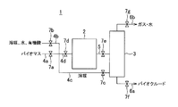
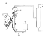
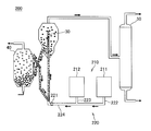
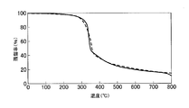
- FIG. 1 is a schematic diagram of a manufacturing apparatus that can carry out a method for manufacturing biocrude according to an embodiment of the present invention. It is a schematic diagram of a hydrocarbon production device according to a first embodiment of the present invention. It is a schematic diagram of a hydrocarbon production device according to a second embodiment of the present invention. It is a schematic diagram of an apparatus for producing hydrocarbons according to a third embodiment of the present invention. It is a figure showing the result of thermogravimetry in an example of the present invention.
- the method for producing biocrude of the present invention includes a mixing step and a solvolysis step.
- Biocrude is a liquid product obtained by solvolysis of biomass.
- biocrude obtained by solvolysis of woody biomass includes oxygen-containing aromatic compounds such as methoxyphenol and alkylphenol derived from lignin, furans derived from cellulose or hemicellulose, and a large number (2 to 80). Degree) Copolymerized polymer compounds and the like are included.
- the mixing step is a step of mixing biomass and a solvent containing an oxygen-containing aromatic compound to obtain a mixture. If these materials are mixed in advance in the mixing step, biomass can be solvolyzed by heating the mixture, which facilitates the production of biocrude.
- Biomass is an organic resource of biological origin, excluding fossil resources.
- the types of biomass include waste biomass, unused biomass, and resource crops (plants cultivated for the production of energy and products).
- waste biomass include paper to be discarded, livestock excreta, food waste, wood generated from construction, sawmill residue, sewage sludge, and the like.
- Unused biomass includes rice straw, straw, rice hull, and the like, and resource crops include sugarcane and corn.
- wood biomass among waste biomass, unused biomass, and resource crops, wood biomass (“woody biomass”) can be suitably used.
- plant oils such as solid or liquid palm oil and olive oil, etc., such as solid or liquid palm oil and olive oil, such as branches and leaves generated during tree felling and lumbering, bark and sawdust generated from sawmills, etc. Wood residue, crushed house materials, pruned branches of street trees, and the like remaining after the removal of the components are listed as woody biomass.
- the biomass used in the present invention is previously pulverized into solid particles. Since the specific surface area of the biomass is increased by the pulverization, the solvolysis reaction proceeds more efficiently than that of the non-pulverized biomass, and the yield of biocrude can be improved.
- the cell wall has a characteristic structure for each plant, and it is sometimes difficult to supply a solvent or an organic acid described below into the plant cells to advance the solvolysis reaction. is there.
- cellulose crystalline fibrils which are the minimum unit of cellulose, are bundled aggregates in which dozens of glucan molecules are aligned in the same direction and are hydrogen-bonded, and hemicellulose clings around the aggregates. It is expected to be a united shape. Although glucan is small as one molecule, each molecule is bundled with a shift. Therefore, the total length of the cellulose crystalline fine fibers becomes large. With such a shape, there is little room for water molecules and a solvent to enter the cellulose crystalline microfibers, so that solvolysis may be difficult.
- the degree of pulverization may be appropriately set in consideration of the cost of pulverization and the cost of solvolysis. For example, in view of these costs and the yield of biocrude, it is preferable to use biomass that has entered between a 75 ⁇ m and 106 ⁇ m sieve after pulverization. Biomass that has passed through a 75 ⁇ m sieve is not likely to be expected to increase the efficiency of the solvolysis reaction because the biomass in the form of particles aggregates and the specific surface area does not substantially increase. In addition, biomass that does not pass through a 106 ⁇ m sieve may not have a large specific surface area to such an extent that an improvement in biocrude yield can be expected.
- the biomass is pulverized (pulverization step) and the pulverized biomass is sieved (sieving step). ) Can be performed before the mixing step. And in a mixing process, the biomass after a sieving process can be mixed. In the case where coarse biomass is mixed in after the sieving step, a step of separating biomass between the 75 ⁇ m and 106 ⁇ m sieves after the sieving step (sorting step) may be performed.
- Pulverizing biomass can be performed using a commonly used pulverizer such as a ball mill, a rod mill, and a jet mill.
- a manual or automatic sieving machine or the like can be used.
- solvent containing oxygen-containing aromatic compound The solvent is used for accelerating the solvolysis reaction of biomass.
- hydrocarbon and water have amphipathic properties (amphiphilicity) so that the solvent can easily penetrate into the tissue of the biomass, and therefore contain oxygen-containing aromatic compounds.
- amphipathic properties amphiphilicity
- the solvent contains an oxygen-containing aromatic compound, the solubility in biomass and its decomposition products increases, and these can be dissolved in the solvent at a high concentration. Therefore, radicals are diluted and dispersed in the solvent to suppress re-polymerization of the decomposition product of biomass, and promote liquefaction (solvolysis) of biomass.
- the oxygen-containing aromatic compound is a substance that is soluble in cellulose, hemicellulose, lignin and its decomposition products, and specifically, methoxyphenols such as guaiacol (2-methoxyphenol), alkylphenols, and vegetable oils Alternatively, an oil or the like can be used.
- the mixture may further contain an organic acid.
- an organic acid which is acidic in an aqueous solution, such as a carboxylic acid or an organic acid having 1 to 6 carbon atoms.
- an organic acid containing at least one of formic acid, acetic acid, propionic acid, and butyric acid can be used. Since the organic acid acts on the solvolysis reaction as an acid catalyst, the liquefaction of biomass can be further promoted.
- biomass can be decomposed even at a lower temperature than thermal decomposition, subcritical water treatment, or supercritical water treatment, and liquefaction becomes possible, and biocrude can be obtained.
- a mixture containing a solvent containing an oxygen-containing aromatic compound and an organic acid containing at least one of formic acid, acetic acid, propionic acid, and butyric acid can be used to make the mixture have a weak pH of about 2 to 3.
- the acidic solution can be used to acid-hydrolyze the cell walls of biomass composed of cellulose, hemicellulose, lignin and the like.
- the mixture may further include water.
- the solvolysis reaction can proceed without requiring a large amount of water.
- the water since the water is contained in the mixture, the water can carry the organic acid serving as the acid catalyst to the inside of the tissue of the biomass, so that the liquefaction of the biomass by the solvolysis can efficiently proceed. .
- the solvolysis reaction can proceed with the water contained in the biomass without adding water to form a mixture. Therefore, water may not be added in the mixing step.
- the solvent containing the oxygen-containing aromatic compound is an amphipathic oxygen-containing aromatic compound
- the organic acid may be acetic acid or an organic acid containing acetic acid as a main component. It is believed that the solvolysis reaction is facilitated by the fact that the mixture contains oxygen-containing aromatic compounds which are especially amphiphilic with water and acetic acid or an organic acid containing acetic acid as a main component.
- oxygen-containing aromatic compound having amphipathic properties both the biomass, which is a carbohydrate, and the water that carries the organic acid are compatible with each other, so that the acid catalyst is easily transported to a reaction site where a solvolysis reaction occurs.
- acetic acid or an organic acid containing acetic acid as a main component can be expected to have a high function as an acid catalyst.
- the content of water in the mixture is preferably 5% by mass or more. By containing 5% by mass or more of water, liquefaction of biomass by solvolysis can efficiently proceed. In addition, when the amount of water in the reaction system for solvolysis is increased, the dissociation of the acid catalyst proceeds, so that the promotion of the solvolysis reaction can be expected.
- the liquefaction rate of biomass by the solvolysis reaction is increased, and biocrude can be obtained with higher yield.
- the content of water in the mixture is preferably set to 40% by mass or less.
- the content of biomass in the mixture is preferably 10 to 30% by mass. If the content of biomass is small, the productivity of biocrude may decrease. Also, if the content of biomass is large, the content of oxygen-containing aromatic compounds and organic acids in the mixture will be reduced accordingly, so that the solvolysis reaction does not proceed sufficiently, and the production time And the yield of biocrude may decrease.
- the biomass, the solvent, and the organic acid may be mixed to obtain a mixture. Therefore, in addition to or instead of the solvent or the organic acid, the biomass, the solvent, and the organic acid may be previously produced by the production method of the present invention.
- Bioclude can be used. That is, a part of the obtained biocrude may be set aside, and this biocrude may be used as a solvent when biomass is subsequently produced using biomass. Further, the biocrude obtained by adding biocrude to the solvent can be used in the subsequent production of biocrude. That is, the biocrude obtained by the production method of the present invention can be used as a solvent in the next production.
- the reason why the biocrude can be used as a raw material in the biocrude obtained by the production method of the present invention is that, for example, when woody biomass is used as a raw material, methoxy such as guaiacol is used as an oxygen-containing aromatic compound. This is because phenols, alkylphenols, and organic acids such as acetic acid are contained. Therefore, the biocrude can be added to the biomass to promote the solvolysis reaction of the biomass without separately adding the oxygen-containing aromatic compound or the organic acid.
- the method for mixing the biomass, the solvent and the organic acid is not particularly limited, and a mixture can be obtained based on a general mixing method.
- these raw materials may be charged into a reaction vessel to be subjected to solvolysis and mixed, or a mixture mixed in another vessel may be charged into the reaction vessel.
- the solvolysis step is a step in which the mixture obtained in the mixing step is heated to 190 to 250 ° C. to solvolyze the mixture.
- the acid catalyst is carried into the tissue of the biomass, and the biomass can be dissolved in the liquefied biocrude.
- the mixture is heated to 190 to 250 ° C. where the reaction is more likely to proceed, whereby the liquefaction of the biomass by the acid catalyst and the transport of the liquefied biocrude from the biomass to the outside by the solvent have a synergistic effect.
- the solvent decomposition reaction proceeds quickly, and a high yield of biocrude can be obtained in a short time.
- the solvolysis reaction becomes insufficient, and the liquefaction of the biomass does not proceed, so that the yield of biocrude may decrease.
- the heating of the mixture exceeds 250 ° C., although the solvolysis reaction easily proceeds, the thermal decomposition reaction also easily proceeds, and carbon monoxide (CO) and carbon dioxide (CO 2 ) are generated from biomass. At the same time, coking also proceeds, and carbon is lost as a gas or a solid, which may decrease the yield of biocrude.
- the solvolysis reaction can proceed sufficiently, and the production of carbon monoxide, carbon dioxide, and coke can be suppressed. Crude yield can be improved.
- biomass, a solvent and an organic acid are mixed in a reactor so as to carry out a solvolysis reaction, and the temperature of the reactor is raised to 190 to 250 ° C., and the temperature is kept for a predetermined time (for example, 1 to 4 hours). By keeping this, the solvolysis reaction proceeds. After the solvolysis step, a liquid product is recovered from the reactor and used as biocrude.
- any device may be used as long as the mixture can be heated at the set temperature and time to perform solvolysis.
- an autoclave or a tubular reactor can be used.
- Fig. 1 shows a schematic diagram of a bio-crude manufacturing device. According to FIG. 1, a process of a method for producing a biocrude that can utilize the biocrude obtained by the previous production, mix it with biomass to obtain a mixture, and produce the biocrude by solvolysis. An example of the flow will be described.
- the biocrude manufacturing apparatus 1 includes a reactor 2 for performing a solvolysis reaction, and a distillation column 3 for distilling a product after the reaction to separate it into biocrude, gas and water. Further, the bio-crude manufacturing apparatus 1 includes introduction lines 4a to 4d for introducing raw materials, an introduction line 5 for introducing a product from the reactor 2 to the distillation column 3, an exhaust line 6a for discharging bio-crude from the distillation column 3, And a discharge line 6b for discharging gas and water from the distillation column 3. Each of the introduction line and the discharge line includes valves 7a to 7g in the middle of the line, so that introduction and discharge can be controlled.
- a solvent containing oxygen-containing aromatic compounds, formic acid, acetic acid, and the like are introduced into an introduction line 4a for introducing biomass into the reactor 2 via an introduction line 4b.
- a mixture obtained by mixing an organic acid containing at least one of propionic acid or butyric acid and, if necessary, water is introduced to obtain a mixture (mixing step).
- the product obtained by the solvolysis reaction is introduced into the distillation column 3 through the introduction line 5, where it is distilled.
- the gas and water fractionated by distillation are discharged from the upper part of the distillation column 3 by the discharge line 6b.
- the liquid product is discharged from the lower part of the distillation column 3 through the discharge line 6a as biocrude and collected.
- the biocrude obtained in the previous production is introduced into the introduction line 4a through the introduction line 4c and mixed with biomass (mixing step), and the mixture is introduced through the introduction line 4d.
- the biocrude can be obtained by introducing into the reactor and subjecting to solvolysis (solvolysis step).
- solvolysis step solvolysis step
- an appropriate amount of a solvent, water, or an organic acid can be mixed and replenished through the introduction line 4d.
- biomass, a solvent, and an organic acid can be mixed and solvolyzed in the same manner as in the first time, without using the biocrude obtained in the first production as a solvent.
- bio-crude manufacturing apparatus 1 it is possible to manufacture bio-crude for the first time using the same apparatus or to repeatedly manufacture bio-crude, which is highly versatile.
- the solvent, organic acid, water, and the like remaining in the biocrude can be repeatedly used, so that the production cost can be reduced.
- the hydrocarbon production method includes a fluid catalytic cracking step of subjecting the biocrude obtained by the above-described biocrude production method to fluid catalytic cracking using a hydrogen donor.
- Fluid catalytic cracking is one of petroleum refining technologies, in which a solid catalyst in powder form is used in a fluidized bed state and brought into contact with an object, and the object is decomposed by a chemical reaction by the action of the catalyst. Also called FCC (Fluid Catalytic Cracking) process.
- FCC Fluid Catalytic Cracking
- biocrude is decomposed by the action of a catalyst.
- the hydrocarbon is a compound made of a carbon atom and a hydrogen atom, and includes a chain hydrocarbon and a cyclic hydrocarbon.
- oxygen-free Drop-in fuels fuels that can be used with existing engines and infrastructures
- fuels and compounds such as aromatic compounds such as benzene, toluene and xylene, and olefins such as ethylene, propylene and butadiene are mentioned.
- Can be These fuels and compounds are generally refined from crude oil and used as petrochemical products. In the present invention, these fuels and compounds are produced from biomass.
- the hydrocarbon in the present invention is not limited to these as long as it is a biodegraded or hydrogen-decomposed hydrocarbon.
- the hydrogen donor is a substance capable of donating hydrogen in the fluid catalytic cracking step and a substance including such a substance.
- a hydrogen donor is an organic compound that has a large H / C (ratio of hydrogen compared to carbon in a compound) and can easily undergo a decomposition reaction by a fluid catalytic cracking reaction and can provide hydrogen by a hydrogen transfer reaction that proceeds simultaneously. is there.
- heavy oil typified by reduced pressure gas oil and residual oil under normal pressure, and the like can be mentioned.
- These heavy oils and the like have a structure in which a linear alkane substituent is developed in a polycyclic aromatic such as alkyltetralin or alkylnaphthalene (for example, the following compound 1), or a linear chain represented by hexadecane or eicosane. It contains an alkane structure (for example, Compound 2 below).
- a linear alkane substituent is developed in a polycyclic aromatic such as alkyltetralin or alkylnaphthalene (for example, the following compound 1), or a linear chain represented by hexadecane or eicosane. It contains an alkane structure (for example, Compound 2 below).
- zeolite or amorphous silica-alumina having appropriate acidity can be used as the catalyst used for fluid catalytic cracking.
- FAU-type zeolites having large pores can be suitably used especially among zeolites in consideration of the molecular size of the raw material.
- the FAU-type zeolite has a high hydrogen transfer reaction activity, hydrogen contained in the hydrogen donor is converted into a hydroxyl group (—OH), an ether bond (—O—), or a carboxyl group (—) contained in biocrude.
- -COOH is passed to an oxygen-containing component having a structure such as -COOH), and the hydrodeoxygenation reaction proceeds to generate water.
- a zeolite having a zeolite lattice constant of 24.20 ° to 24.45 ° As a catalyst.
- the zeolite lattice constant indicates the size of the crystal lattice.
- the larger the zeolite lattice constant the higher the catalytic activity and the content of oxygen-containing compounds, CO, and CO 2 in the product after fluid catalytic cracking. And more hydrocarbons can be produced. This effect can be particularly obtained by using a zeolite having a zeolite lattice constant of 24.20 ° to 24.45 °.
- the method for producing hydrocarbons may include steps other than the fluid catalytic cracking step. For example, a catalyst regeneration step of regenerating a catalyst by removing coke adhering to the catalyst surface by fluid catalytic cracking by combustion, a step of separating and purifying a decomposition product obtained by fluid catalytic cracking, and the like are included.
- a hydrocarbon production apparatus 100 schematically shown in FIG. 2 is used in a fluid catalytic cracking process, and is a raw material storage tank 10 for storing raw materials and a raw material supply means for supplying raw materials to a riser reaction tube 30.
- a raw material supply pipe 20, a riser reaction pipe 30 that is a reactor in which fluid catalytic cracking is performed, a regeneration tower 40 for regenerating a catalyst to which coke is attached, and a hydrocarbon obtained in the riser reaction pipe 30 are distilled to obtain A distillation column 50 for fractionating into components.
- a valve 21 for adjusting the supply amount of the raw material is provided between the raw material supply tube 20 and the riser reaction tube 30.
- the raw material biocrude and the hydrogen donor are mixed in advance and stored in the raw material storage tank 10 as a raw material slurry.
- raw material and steam are supplied to riser reaction tube 30, and the raw material has zeolite or moderate acidity at a temperature of about 450 ° C. to 650 ° C. It is decomposed by contact with a finely divided solid acid catalyst (shown by white circles in FIG. 2) obtained by turning amorphous silica-alumina into fine powder.
- a finely divided solid acid catalyst shown by white circles in FIG. 2 obtained by turning amorphous silica-alumina into fine powder.
- a hydrogen donor such as heavy oil is decomposed at an active site, which is an active site scattered in micropores or mesopores of a solid acid catalyst, and an olefin is generated via a carbenium ion as an intermediate. Further, as the cyclization reaction and the hydrogen transfer reaction proceed, oxygen in the compound contained in the biocrude is removed as water, and decomposition proceeds.
- the catalyst to which the coke adhered after the reaction (the coking catalyst indicated by a black circle ( ⁇ ) in FIG. 2) is heated at 600 ° C. to 800 ° C. in the regeneration tower 40.
- the fuel is regenerated by being burned at a high temperature to remove coke, and supplied again to the riser reaction tube 30 as a regenerated catalyst (indicated by a white circle ( ⁇ ) in FIG. 2).
- air is sent from the lower part of the regeneration tower 40, and carbon monoxide, carbon dioxide, and water are released from the upper part of the regeneration tower 40 as the coke is burned.
- a part of the regenerated catalyst is withdrawn and a new catalyst is supplied.
- the reaction system of the fluid catalytic cracking reaction proceeds as described above.
- the reaction product obtained in the riser reaction tube 30 is sent to the distillation column 50 and fractionated into each component.
- a light fraction such as propylene, butene, or gasoline
- LCO light cycle oil
- HCO heavy cycle oil
- CSO slurry oil
- the hydrocarbon production apparatus 200 includes a raw material storage tank 210 that stores raw materials, a raw material supply pipe 220 that is a raw material supply unit that supplies the raw materials to the riser reaction pipe 30, a riser reaction pipe 30 in which fluid catalytic cracking is performed,
- the apparatus includes a regeneration tower 40 for regenerating a catalyst to which coke has adhered, and a distillation tower 50 for distilling hydrocarbons obtained in the riser reaction tube 30 to fractionate the components.
- the raw material storage tank 210 is configured to include a biocrude storage tank 211 that stores biocrude and a hydrogen donor storage tank 212 that stores a hydrogen donor, and is a second embodiment of a hydrocarbon manufacturing apparatus.
- the biocrude and the hydrogen donor are stored in separate storage tanks.
- the raw material supply pipe 220 includes a biocrude supply pipe 222 connected to the biocrude storage tank 211, a hydrogen donor supply pipe 223 connected to the hydrogen donor storage tank 212, and a biocrude supply pipe 222.
- a mixing supply pipe 224 that is joined to the body supply pipe 223 and connected to the riser reaction pipe 30.
- the biocrude and the hydrogen donor are separately stored, mixed in the mixing supply pipe 224, and supplied to the riser reaction pipe 30. Further, a valve 221 for adjusting the supply amount of the raw material is provided between the mixing supply pipe 224 and the riser reaction pipe 30. Note that, in the present embodiment, the biocrude storage tank 211 is provided upstream of the hydrogen donor storage tank 212, but the hydrogen donor storage tank 212 may be provided upstream.
- the hydrocarbon producing apparatus 300 is a raw material storage tank 310 for storing a raw material, a raw material supply pipe 320 that is a raw material supply means for supplying a raw material to a riser reaction tube 30 described below, and a reactor in which fluid catalytic cracking is performed.
- the reactor includes a riser reaction tube 30, a regeneration tower 40 for regenerating a catalyst to which coke has adhered, and a distillation column 50 for distilling hydrocarbons obtained in the riser reaction tube 30 to fractionate each component.
- the raw material storage tank 310 is configured to include a biocrude storage tank 311 for storing biocrude and a hydrogen donor storage tank 312 for storing a hydrogen donor, and is a third embodiment of a hydrocarbon manufacturing apparatus.
- the biocrude and the hydrogen donor are stored in separate storage tanks.
- the raw material supply pipe 320 includes a biocrude supply pipe 322 (biocrude supply unit) connected to the biocrude storage tank 311 and a hydrogen donor supply pipe 323 (hydrogen donor) connected to the hydrogen donor storage tank 312. Supply unit).
- the biocrude and the hydrogen donor are stored separately, and supplied to the riser reaction tube 30 through separate supply pipes.
- a valve 321 a for adjusting the supply amount of biocrude is provided between the biocrude supply pipe 322 and the riser reaction pipe 30, and hydrogen is supplied between the hydrogen donor supply pipe 323 and the riser reaction pipe 30.
- a valve 321b for adjusting the supply amount of the donor is provided.
- the biocrude and the hydrogen donor may be separately supplied. Further, as a raw material supply means, a biocrude supply unit for supplying biocrude and a hydrogen donor supply unit for supplying a hydrogen donor may be separately provided.
- the biomass is stably contained in the hydrogen donor slurry. It can be configured like the hydrocarbon production apparatus 100 of the first embodiment or the hydrocarbon production apparatus 200 of the second embodiment so as to be dispersed.
- the raw material slurry obtained by mixing the biocrude and the hydrogen donor is supplied to the lower part of the riser reaction tube 30 where the fluid catalytic cracking reaction is performed.
- the biocrude and the hydrogen donor are stored in separate tanks as in the hydrocarbon production apparatus 200 shown in FIG. 3, and the raw materials mixed in the mixing supply pipe 224 are subjected to a riser reaction. Or it can be configured to supply to the tube 30.
- the biocrude and the hydrogen donor are stored in separate tanks, and separate supply pipes (biocrude It is preferable to be configured to be supplied via the supply pipe 322 and the hydrogen donor supply pipe 323). Since the biocrude and the hydrogen donor are separately supplied, the biocrude and the hydrogen donor do not mix in the supply pipe, so that the deposition of biomass can be prevented. Thereby, blockage of the supply pipe or the supply nozzle of the raw material can be prevented.
- the catalyst which is a solid particle, flows at a high flow rate in the riser reaction tube 30 and does not block.
- the configuration of the hydrocarbon production apparatus can be selected according to the properties of the raw materials, such as biocrude and the hydrogen donor.
- the biomass decomposition reaction proceeds at a lower temperature than the thermal decomposition, subcritical water treatment, or supercritical water treatment by solvolysis of biomass.
- hydrocarbons of the present invention when biocrude is catalytically cracked together with a hydrogen donor in the fluidized catalytic cracking step, deoxygenation is performed by a hydrodeoxygenation reaction, and a large amount of oxygen is converted into water. Therefore, generation of carbon monoxide and carbon dioxide can be suppressed, and loss of carbon resources can be reduced.
- hydrocarbons can be efficiently produced from biomass. It is presumed that a monocyclic aromatic compound is generated by hydrogenolysis of the polycyclic aromatic compound constituting the biomass.
- the hydrocarbon production system uses the biocrude production method and the hydrocarbon production method of the present invention.
- the production of biocrude and the production of hydrocarbons may be performed in a close place, performed in a place apart from each other, and transporting the biocrude obtained by the method for producing biocrude. May be supplied to the fluid catalytic cracking step of the hydrocarbon production method. Whether the production of biocrude and the production of hydrocarbons are carried out in a close place or in places apart from each other can be appropriately selected depending on the location of biomass production and facilities, and the like.
- the equipment used to produce biocrude should be installed in the forested area, and the production of biocrude and the production of hydrocarbons should be established.
- Production can be performed at a location remote from each other.
- the biocrude obtained by the biocrude manufacturing method can be transported by a tank lorry, a truck, a ship, an airplane, or the like.
- biocrude may be transported by a transport pipe.
- the transportation of the biocrude may be performed not only by transportation by vehicle but also by selecting other transportation means in consideration of transportation costs.
- ⁇ a place separated from each other '' does not mean transporting the reactants by directly connecting the bio-crude production facility and the hydrocarbon production facility with pipes or the like, but via batch transport such as tank trucks and trucks. This indicates that they are far enough to be transported. If the bio-crude manufacturing equipment is provided in a place where tank trucks and trucks cannot pass as described above, the reactants are transported through transport pipes and the like to the places where it can pass, and then The reactants may be transported by batch transportation to a location where a facility for producing hydrocarbons is provided.
- the production of biocrude may be carried out in a biomass production area.
- the production of biocrude may be performed at a mountain site (a site nearby mountain) where there is a log used as a material of the woody biomass.
- woody biomass production area and the oil refinery are often separated from each other. Because woody biomass is bulkier than biocrude, transporting woody biomass from a woody biomass production site to a hydrocarbon production facility (a facility equipped with biocrude production equipment and hydrocarbon production equipment) increases transportation costs. Become. Therefore, by producing biocrude in a biomass production area, woody biomass that is bulkier than biocrude becomes liquid biocrude, and can be transported by a tank lorry or the like. For this reason, the transportation cost can be reduced as compared with transporting woody biomass that is bulkier than biocrude as it is.
- the ratio indicates a mass ratio.
- Simulated cedar is a model material that imitates the composition of cedar, and is a mixture of cellulose and lignin mixed at a mass ratio of 6: 4.
- the content of lignin in Japanese cedar is about 30% by mass (Takahide Haraguchi, et al. (1993) Wood Chemistry, Buneido Publishing), but the decomposition of lignin in fluid catalytic cracking is understood.
- the content of lignin in the simulated cedar was set to 40% by mass, which was larger than that of cedar.
- the chip-shaped domestic cedar was pulverized in advance using a planetary ball mill (Fritsch Japan, model number P-7), and then sieved to use cedar chips between the 75 ⁇ m and 106 ⁇ m sieves as raw materials.
- the water content in the cedar chips is about 8% by mass.
- the amount of water in the reaction vessel is controlled by adjusting the amount of water added in consideration of the amount of water in the cedar chips.
- Palm kernel shell is a kernel shell in the fruit of palm palm, and is a residue after the oil is taken out at a palm oil factory.
- PKS chips As palm kernel shell chips (hereinafter sometimes referred to as “PKS chips”), PKS is preliminarily pulverized using an impact-type pulverizer / dryer (Kds Micronex, manufactured by Kitagawa Iron Works Co., Ltd.), and then sieved. After that, what was between the 75 ⁇ m and 106 ⁇ m sieves was used as a raw material.
- the water content in the PKS chip is 9 to 12% by mass.
- the amount of water in the reaction vessel is controlled by adjusting the amount of water added in consideration of the amount of water in the PKS chip.
- thermogravimetric analysis was performed using cedar chips and simulated cedar as samples.
- a thermogravimetric analyzer (TGA-51, manufactured by Shimadzu Corporation) was used to raise the temperature from room temperature to 800 ° C. at 10 K / min under a nitrogen atmosphere (50 ml / min).
- FIG. 5 shows the result of the thermogravimetric analysis.
- the vertical axis shows the residual ratio (%, the value calculated by calculating the weight ratio of the residue to the weight of the sample subjected to the thermogravimetric analysis), and the horizontal axis shows the temperature.
- Simulated cedar, guaiacol and water were mixed at the ratios shown in Table 1 (mixing step) and supplied to an autoclave (MMJ-500, manufactured by OM Lab-Tech Co., Ltd., internal volume: 430 ml) to perform a solvolysis reaction (solvolysis step). ).
- the reaction temperature was set to 150 to 300 ° C. for Test Examples 1 to 4, and the reaction time was fixed at 1 hour.
- the generated gas product (gas) was collected in a gas bag and analyzed using gas chromatography (GC-8A, manufactured by Shimadzu Corporation). Detection was performed by a thermal conductivity type detector.
- gas chromatography GC-8A, manufactured by Shimadzu Corporation.
- the solid product after washing with acetone was dried under reduced pressure at room temperature overnight using a desiccator and an aspirator (manufactured by Tokyo Rika Kikai, Model No. A-3S), and the mass was measured.
- the carbon content in the dried solid product was measured using an NC analyzer (SUMIGRAPH @ NC-1000, manufactured by Sumika Chemical Analysis Service, Ltd.).
- the yield of biocrude was increased by setting the reaction temperature to 200 to 250 ° C. From this result, it was recognized that the higher the reaction temperature, the easier the solvolysis reaction proceeded. On the other hand, as shown in the result of the thermogravimetric analysis in FIG. 5, it was considered that the pyrolysis reaction occurred under the condition of 300 ° C., thereby lowering the biocrude yield.
- the cell wall of woody biomass has a characteristic structure for each plant.
- Cellulose crystalline fibrils which are the smallest unit of cellulose, are bundled aggregates in which several tens of glucan molecules are aligned in the same direction and hydrogen-bonded, and hemicellulose is wrapped around the aggregates. Have been. For this reason, it is known in the field of plant physiology and structure that there is little room for water molecules to enter the crystal region of the cellulose crystal, and it is difficult to undergo solvolysis. That is, it is not easy to advance the solvolysis reaction simply by supplying a weak acid aqueous solution such as an organic acid into plant cells.
- Test Example 12 was a sample obtained by using domestic cedar as biomass.
- Cedar, guaiacol, water and acetic acid were mixed at the ratios shown in Table 7 (mixing step), and a solvolysis reaction was carried out in the same manner as in Test Examples 1 to 4 (solvolysis step).
- the reaction temperature of Test Examples 12 and 13 was 200 ° C., and the reaction time was 1 hour.
- Test Examples 15 and 18 were designated as Test Examples 15, 16, and 18.
- Test Examples 14 and 17 using pulverized PKS comparison was made on the yield of biocrude and reduction in molecular weight.
- PKS, guaiacol, water and acetic acid were mixed at the ratios shown in Table 9 (mixing step), and a solvolysis reaction was carried out in the same manner as in Test Examples 1 to 4 (solvolysis step).
- the reaction temperature was 250 ° C.
- the reaction time was 2 hours.
- the reaction temperature of Test Examples 17 and 18 was 250 ° C., and the reaction time was 0.5 hour.
- an oxygen-containing aromatic compound solvent such as guaiacol is used to break down the structure of cellulose.
- the oxygen-containing aromatic compound solvent has the ability to dissolve lignin, which is responsible for the structural strength of plants, but has high solubility in water. Accordingly, the oxygen-containing aromatic compound solvent promotes acid hydrolysis of cellulose and hemicellulose by supplying a weak acid aqueous solution such as an organic acid into cells while dissolving lignin to destroy plant cell walls.
- the mechanism of solvolysis differs depending on the plant structure of the woody biomass, and the optimal conditions for solvolysis vary greatly.
- acid solvent decomposition can proceed even if the concentration of water in the solvent is low, whereas the concentration of water in the solvent is reduced when PKS is used. It is important to make it higher than in the case of cedar chips.
- an aqueous phase appears in the cells of the cedar chip, in which acetic acid dissociates to a pH of about 2 to 3, so that the solvolysis of cellulose or hemicellulose has progressed.
- the cambium is used, and the cedar has a mechanism whereby moisture containing nutrients absorbed from the roots is efficiently transported to the cambium via conduits. It is considered that this high-ordered conduit efficiently transported and distributed water to cells that were not in direct contact with the solvent containing the oxygen-containing aromatic compound.
- Table 13 shows the number of moles of hydronium ions (H 3 O + : proton monohydrate) with respect to PKS in the mixture. This is a reference for comparing the amount of protons serving as a catalyst in the solvolysis reaction.
- the amount of water in the mixture is increased, the amount of dissociation of an organic acid such as acetic acid is increased, so that the number of protons having a catalytic action is increased and the solvolysis reaction is likely to proceed.
- PKS has a high lignin content and high strength, it is considered that a certain technique is required to pulverize PKS. However, after the PKS is crushed, it is expected that the decomposition of cellulose and hemicellulose will proceed, and that the molecular weight will be further reduced.
- cat / oil is the abundance ratio of the raw material (kg / m 3 ) and the catalyst (kg / m 3 ) in the batch type reactor, the raw material supply amount (kg / hr) to the flow type reactor and the catalyst It indicates the ratio of the supply amount (kg / hr) or the abundance ratio of the catalyst (kg) to the oil raw material (kg). For example, if a large amount of the catalyst is present in the reactor, the reaction rate increases.
- the cat / oil parameter is a key reaction condition in fluidized catalytic cracking processes that convert biocrude into hydrocarbons.
- Fluid catalytic cracking process Using the biocrude obtained in Test Example 12 as a raw material, fluid catalytic cracking was performed using a zeolite catalyst and eicosane as a hydrogen donor to produce a hydrocarbon.
- a fixed bed flow reactor in accordance with ASTM D3907-92 was used as a reactor for fluid catalytic cracking, and an industrial RFCC equilibrium catalyst containing a FAU type zeolite was used as a catalyst.
- the UCS value (zeolite lattice constant) of the industrial RFCC equilibrium catalyst was 24.27 ° (2.427 nm) to 24.40 ° (2.440 nm) in Test Examples AD.
- the experiment was performed according to the method specified in ASTM D5154-10.
- the product obtained by the fluid catalytic cracking process was analyzed as follows. First, the reaction product passed through the catalyst tank was cooled in an ice bath, and gas-liquid separation was performed. Then, a gas product and a liquid product were recovered. The gas was recovered by water replacement. Hydrogen, carbon monoxide, and carbon dioxide contained in gaseous products are analyzed by gas chromatography with a thermal conductivity type detector (manufactured by Shimadzu Corporation, GC-8A), and hydrocarbons are equipped with a flame ionization type detector. The analysis was performed by gas chromatography (GC-2014, manufactured by Shimadzu Corporation).
- the hydrocarbons and oxygenated compounds in the liquid product were analyzed by gas chromatography with flame ionization detector (GC-2014, manufactured by Shimadzu Corporation) and gas chromatograph mass spectrometer (GCMS-QP2010 @ Plus, manufactured by Shimadzu Corporation). And analyzed.
- the oxygen-containing compound does not include carbon monoxide, carbon dioxide, and water.
- the amount of coke produced was determined from the change in the weight of the catalyst tank before and after the reaction, and the components were analyzed using an NC analyzer (SUMIGRAPH @ NC-1000, manufactured by Sumika Chemical Analysis Service, Ltd.). Components that could not be detected by gas chromatography were designated as others. In addition, although it was visually confirmed that water was contained in the liquid product, it was difficult to determine the quantity by gas chromatography. In addition, it is considered that undecomposed high molecular oxygen components are also contained. Table 15 shows the result of analyzing the composition of the reaction product obtained in the fluid catalytic cracking step.
- biocrude can be produced in high yield by solvolysis using biomass as a raw material.
- a hydrocarbon can be produced in high yield by hydrodeoxygenating biocrude while suppressing the production of carbon monoxide and carbon dioxide. .
Landscapes
- Chemical & Material Sciences (AREA)
- Oil, Petroleum & Natural Gas (AREA)
- Engineering & Computer Science (AREA)
- Chemical Kinetics & Catalysis (AREA)
- General Chemical & Material Sciences (AREA)
- Organic Chemistry (AREA)
- Crystallography & Structural Chemistry (AREA)
- Inorganic Chemistry (AREA)
- Life Sciences & Earth Sciences (AREA)
- Wood Science & Technology (AREA)
- Production Of Liquid Hydrocarbon Mixture For Refining Petroleum (AREA)
Abstract
バイオマスを用いて、炭素資源の損失を抑制して、効率よく炭化水素を製造することができる炭化水素の製造方法およびバイオクルードの製造方法を提供する。 バイオマスと、含酸素芳香族化合物を含む溶媒を混合して混合物を得る混合工程と、前記混合物を190~250℃に加熱して、当該混合物を加溶媒分解する加溶媒分解工程と、を含む、バイオクルードの製造方法。
Description
本発明は、炭化水素の製造方法およびバイオクルードの製造方法に関するものである。
近年、石油等の化石資源の枯渇が懸念されていることや、エネルギー需要が増大していることを背景として、代替資源の開発が求められており、例えば、植物等のバイオマスを原料として、石油に代替する輸送用燃料の合成手法が種々提案されている。
石油に代替する燃料の合成手法として、植物等のバイオマスを原料として液体燃料を製造する方法が研究開発されている(例えば、特許文献1参照)。特許文献1に記載の液体燃料の製造方法は、木質バイオマスと有機溶媒とを混合して、250℃~400℃にて熱分解することにより液化処理し、この分解物を分離して液体燃料を得るものである。
しかしながら、特許文献1に記載の従来の熱分解プロセスや、亜臨界水処理プロセスまたは臨界水処理プロセスを用いてバイオマスから炭化水素を製造する場合、バイオマスの酸素含有率が高いこと、また、バイオマスを高温処理することから、一酸化炭素(CO)や二酸化炭素(CO2)等の無機ガスが多く発生して、バイオマスに含まれる炭素資源の損失が大きいという問題があった。
従って、本発明は、上記のような問題点に着目し、バイオマスを用いて、炭素資源の損失を抑制して、効率よく炭化水素を製造することができる炭化水素の製造方法およびバイオクルードの製造方法を提供することを目的とする。
上記課題を解決するために、本発明のバイオクルードの製造方法は、バイオマスと、含酸素芳香族化合物を含む溶媒を混合して混合物を得る混合工程と、前記混合物を190~250℃に加熱して、当該混合物を加溶媒分解する加溶媒分解工程と、を含む。
前記混合物は、ギ酸、酢酸、プロピオン酸または酪酸の少なくともいずれかを含む有機酸を含んでもよい。
前記混合物は水を含んでもよい。
前記含酸素芳香族化合物を含む溶媒は、両親媒性の含酸素芳香族化合物であり、前記混合物は、酢酸または酢酸を主成分とする有機酸を含んでもよい。
前記混合工程の前に、前記バイオマスを粉砕する粉砕工程と、粉砕後の前記バイオマスを篩分けする篩分け工程と、を含み、前記混合工程は、前記篩分け工程後のバイオマスを混合してもよい。
前記混合物中の前記バイオマスの含有量が10~30質量%であり、水の含有量が5~40質量%であってもよい。
バイオクルード中の分子量1000未満のバイオクルードの含有量が、38質量%以上であってもよい。
また、上記課題を解決するために、本発明の炭化水素の製造方法は、前記バイオクルードの製造方法により得た前記バイオクルードを、水素供与体を用いて流動接触分解する流動接触分解工程を含む。
前記流動接触分解に、ゼオライト格子定数が24.20Å~24.45Åのゼオライトを触媒として用いてもよい。
本発明のバイオクルードの製造方法によれば、バイオマス、所定の溶媒、および有機酸を混合して所定温度で加溶媒分解することにより、従来の熱分解や亜臨界水処理または超臨界水処理する方法よりも低温でバイオマスを液化させることができる。
また、本発明の炭化水素の製造方法によれば、本発明の方法により得られたバイオクルードを、水素供与体を用いて流動接触分解する工程において、バイオクルードを水素供与体とともに接触分解した時に、水素化脱酸素反応により脱酸素が行われて、多くの酸素が水として除かれるため、一酸化炭素や二酸化炭素の生成が抑制され、炭素資源の損失を少なくすることができる。これにより、バイオマスから効率よく炭化水素を製造することができる。
以下、本発明の具体的な実施形態について、図面を参照しつつ説明する。
[バイオクルードの製造方法]
本発明のバイオクルードの製造方法は、混合工程と、加溶媒分解工程とを含む。
本発明のバイオクルードの製造方法は、混合工程と、加溶媒分解工程とを含む。
(バイオクルード)
バイオクルードは、バイオマスを加溶媒分解して得られる液体生成物である。例えば、木質バイオマスを加溶媒分解して得られたバイオクルードには、リグニン由来のメトキシフェノールおよびアルキルフェノール等、セルロースまたはヘミセルロース由来のフラン等の含酸素芳香族化合物と、これらが多数(2~80個程度)共重合した高分子化合物等が含まれている。
バイオクルードは、バイオマスを加溶媒分解して得られる液体生成物である。例えば、木質バイオマスを加溶媒分解して得られたバイオクルードには、リグニン由来のメトキシフェノールおよびアルキルフェノール等、セルロースまたはヘミセルロース由来のフラン等の含酸素芳香族化合物と、これらが多数(2~80個程度)共重合した高分子化合物等が含まれている。
〈混合工程〉
混合工程は、バイオマスと、含酸素芳香族化合物を含む溶媒を混合して混合物を得る工程である。混合工程によりこれらの材料を予め混合しておけば、混合物を加熱することでバイオマスを加溶媒分解できるため、バイオクルードの製造が容易となる。
混合工程は、バイオマスと、含酸素芳香族化合物を含む溶媒を混合して混合物を得る工程である。混合工程によりこれらの材料を予め混合しておけば、混合物を加熱することでバイオマスを加溶媒分解できるため、バイオクルードの製造が容易となる。
(バイオマス)
バイオマスは、生物由来の有機性資源であり、化石資源を除いたものである。バイオマスの種類には、廃棄物系バイオマス、未利用バイオマス、および資源作物(エネルギーや製品の製造を目的に栽培される植物等)等がある。廃棄物系バイオマスは、廃棄される紙、家畜排せつ物、食品廃棄物、建設発生木材、製材工場残材、下水汚泥等が挙げられる。また、未利用バイオマスとしては、稲わら、麦わら、もみ殻等が挙げられ、資源作物としては、さとうきびやトウモロコシ等が挙げられる。
バイオマスは、生物由来の有機性資源であり、化石資源を除いたものである。バイオマスの種類には、廃棄物系バイオマス、未利用バイオマス、および資源作物(エネルギーや製品の製造を目的に栽培される植物等)等がある。廃棄物系バイオマスは、廃棄される紙、家畜排せつ物、食品廃棄物、建設発生木材、製材工場残材、下水汚泥等が挙げられる。また、未利用バイオマスとしては、稲わら、麦わら、もみ殻等が挙げられ、資源作物としては、さとうきびやトウモロコシ等が挙げられる。
本発明では、特に、廃棄物系バイオマス、未利用バイオマス、および資源作物のうち、木材からなるバイオマス(「木質バイオマス」)を好適に使用することができる。具体的には、樹木の伐採や造材のときに発生した枝、葉などの林地残材、製材工場などから発生する樹皮やおがくず等、固形または液状のパーム油やオリーブ油等の植物油や目的とする成分を取り除いた後に残る絞り粕、住宅の解体材や街路樹の剪定枝等が、木質バイオマスとして挙げられる。
本発明に用いるバイオマスは、予め粉砕されて固体粒子となっていることが好ましい。粉砕されていることにより、バイオマスの比表面積が大きくなるので、粉砕されていないものと比べてより効率的に加溶媒分解反応が進み、バイオクルードの収量を向上させることができる。
特に木質バイオマスの場合には、細胞壁は植物ごとに特徴的な構造をしており、植物の細胞内に後述する溶媒や有機酸を供給して加溶媒分解反応を進行させることが困難な場合がある。
例えば、セルロースの最小単位であるセルロース結晶性微繊維は、数十本のグルカン分子が同一方向に並んで水素結合している束状の会合体であり、さらにその会合体の周りをヘミセルロースがまとわりついて結束した形状と予想されている。グルカンは一分子としては小さいものの、各分子がずれながら束ねられている。そのため、セルロース結晶性微繊維の繊維長の全長は大きくなる。このような形状であると、セルロース結晶性微繊維へ水分子や溶媒が入り込む余地が少ないため、加溶媒分解され難くなるおそれがある。
そのため、木質バイオマスでは、粉砕によりセルロース結晶性微繊維へ水分子や溶媒が入り込む余地ができるため、加溶媒分解され易くなる結果、バイオクルードの収量を向上させることができる。
粉砕の程度は、粉砕にかかるコストと加溶媒分解時にかかるコストとを考慮して、適宜設定すればよい。例えば、これらのコストやバイオクルードの収量を考慮すると、粉砕後に75μmと106μmの篩の間に入ったバイオマスを用いることが好ましい。75μmの篩を通過するバイオマスは、粒子状のバイオマスが凝集してしまい、実質的には比表面積が大きくならないため、加溶媒分解反応の効率化が期待できないおそれがある。また、106μmの篩を通過しないバイオマスは、バイオクルードの収量の向上が期待できる程度に比表面積が大きくない場合がある。
バイオマスを粉砕して75μmと106μmの篩の間に入ったものを用いるためには、例えば、混合工程の前に、バイオマスを粉砕し(粉砕工程)、粉砕後のバイオマスを篩分け(篩分け工程)するという各工程をとることができる。そして、混合工程において、篩分け工程後のバイオマスを混合することができる。なお、篩分け工程後に粗大なバイオマスが混入するような場合には、篩分け工程後に75μmと106μmの篩の間に入ったバイオマスを選別する工程(選別工程)を行ってもよい。
バイオマスの粉砕には、ボールミル、ロッドミルやジェットミル等、通常用いることのできる粉砕機を用いることができる。また、篩分けや選別についても、手動や自動の篩機等を用いることができる。
(含酸素芳香族化合物を含む溶媒)
溶媒は、バイオマスの加溶媒分解反応を促進させるために用いるものである。そのためには、バイオマスの組織中へ溶媒が侵入し易くなるように、炭化水素および水の両方に親媒性(両親媒性)を示すことが重要であり、そのために含酸素芳香族化合物を含む溶媒を使用する。
溶媒は、バイオマスの加溶媒分解反応を促進させるために用いるものである。そのためには、バイオマスの組織中へ溶媒が侵入し易くなるように、炭化水素および水の両方に親媒性(両親媒性)を示すことが重要であり、そのために含酸素芳香族化合物を含む溶媒を使用する。
また、溶媒に含酸素芳香族化合物が含まれることにより、バイオマスおよびその分解生成物への溶解性が高くなり、これらを溶媒中に高濃度で溶解できる。そのため、ラジカルが溶媒中に希釈分散されてバイオマスの分解生成物の再重合が抑制され、バイオマスの液化反応(加溶媒分解)を促進させることができる。
含酸素芳香族化合物としては、セルロース、ヘミセルロース、リグニンおよびその分解生成物に対して溶解性のある物質であり、具体的にはグアイアコール(2-メトキシフェノール)等のメトキシフェノール類、アルキルフェノール類、植物油または油脂等を用いることができる。
(有機酸)
本発明において、混合物はさらに有機酸を含んでもよい。有機酸としては、水溶液中で酸性を示す有機酸、例えば、カルボン酸や炭素数1~6の有機酸等を使用することが好ましい。具体的にはギ酸、酢酸、プロピオン酸または酪酸の少なくともいずれかを含む有機酸を用いることができる。有機酸が酸触媒として加溶媒分解反応に作用するので、バイオマスの液化反応をより促進させることができる。
本発明において、混合物はさらに有機酸を含んでもよい。有機酸としては、水溶液中で酸性を示す有機酸、例えば、カルボン酸や炭素数1~6の有機酸等を使用することが好ましい。具体的にはギ酸、酢酸、プロピオン酸または酪酸の少なくともいずれかを含む有機酸を用いることができる。有機酸が酸触媒として加溶媒分解反応に作用するので、バイオマスの液化反応をより促進させることができる。
混合物として、バイオマスおよび含酸素芳香族化合物と共に、有機酸が含まれることにより、加溶媒分解工程においてバイオマスの加溶媒分解が促進される。そのため、熱分解や亜臨界水処理または超臨界水処理よりも低温でもバイオマスが分解することができ、液化が可能となってバイオクルードを得ることができる。
特に木質バイオマスを用いる場合には、混合物に含酸素芳香族化合物を含む溶媒と、ギ酸、酢酸、プロピオン酸または酪酸の少なくともいずれかを含む有機酸を含めることで、これらがpH2~3程度の弱酸性溶液となって、セルロース、ヘミセルロースおよびリグニン等で構成されるバイオマスの細胞壁を酸加水分解することができる。
(水)
本発明において、混合物はさらに水を含んでもよい。後述する加溶媒分解工程では、多量の水を必要とせずに加溶媒分解反応を進めることができる。ただし、混合物中に水が含まれていることにより、水が酸触媒となる有機酸をバイオマスの組織の内部へ運ぶことができるため、加溶媒分解によるバイオマスの液化を効率よく進行させることができる。
本発明において、混合物はさらに水を含んでもよい。後述する加溶媒分解工程では、多量の水を必要とせずに加溶媒分解反応を進めることができる。ただし、混合物中に水が含まれていることにより、水が酸触媒となる有機酸をバイオマスの組織の内部へ運ぶことができるため、加溶媒分解によるバイオマスの液化を効率よく進行させることができる。
なお、バイオマスに水が適量含まれる場合、水を添加して混合物としなくても、バイオマスに含まれる水により加溶媒分解反応を進めることができる。そのため、混合工程では、水を添加しない場合がある。
また、本発明において、含酸素芳香族化合物を含む溶媒は、両親媒性の含酸素芳香族化合物であり、有機酸は、酢酸または酢酸を主成分とする有機酸であってもよい。加溶媒分解反応は、混合物が特に水と両親媒性の含酸素芳香族化合物、および酢酸または酢酸を主成分とする有機酸を含むことにより、促進すると考えられる。両親媒性の含酸素芳香族化合物であれば、炭水化物であるバイオマスと有機酸を運ぶ水の両方との相性が良いため、加溶媒分解反応が起こる反応場へ酸触媒が運ばれ易くなる。また、酢酸または酢酸を主成分とする有機酸であれば、酸触媒としての高い機能が期待できる。
混合物中の水の含有量は、5質量%以上であることが好ましい。5質量%以上の水が含まれていることにより、加溶媒分解によるバイオマスの液化を効率よく進行させることができる。また、加溶媒分解の反応系内の水分量を増加させると、酸触媒の解離が進むために加溶媒分解反応の促進が期待できる。
特に、水の含有量を15質量%以上とすることで、加溶媒分解反応によるバイオマスの液化率が高くなり、より高収率でバイオクルードを得ることができる。
ただし、水の含有量が多すぎると、それに応じて混合物中のバイオマスや含酸素芳香族化合物、有機酸の含有量が少なくなってしてしまうことで、反応が抑制されるおそれがある。そのため、混合物中の水の含有量は、40質量%以下とすることが好ましい。
そして、バイオクルードの収量や製造コストを考慮すると、混合物中のバイオマスの含有量は10~30質量%であることが好ましい。バイオマスの含有量が少ないと、バイオクルードの生産性が低下するおそれがある。また、バイオマスの含有量が多いと、それに応じて混合物中の含酸素芳香族化合物や有機酸の含有量が少なくなってしてしまうことで、加溶媒分解反応が十分に進行せず、製造時間が長くなるおそれやバイオクルードの収量が低下するおそれがある。
また、混合工程では、上記のバイオマス、溶媒および有機酸を混合して混合物を得ればよいため、溶媒や有機酸に加えて、または、これらに代えて、本発明の製造方法によって以前に製造したバイオクルードを用いることができる。すなわち、得られたバイオクルードの一部を取り置いておき、このバイオクルードを、次にバイオマスを用いてバイオクルードを製造する際に溶媒として用いてもよい。また、バイオクルードを溶媒に添加して得られたバイオクルードを、次にバイオクルードを製造する際に用いることができる。すなわち、本発明の製造方法で得られたバイオクルードを、次の製造において溶媒として用いることができる。
このようにバイオクルードを原料として用いることができるのは、本発明の製造方法により得られたバイオクルードには、例えば、原料として木質バイオマスを用いた場合、含酸素芳香族化合物としてグアイアコール等のメトキシフェノール類、アルキルフェノール類や、酢酸等の有機酸が含まれているからである。そのため、含酸素芳香族化合物や有機酸を個別に加えなくても、バイオマスへバイオクルードを添加して、バイオマスの加溶媒分解反応を促進させることができる。
(混合方法)
バイオマスと、溶媒および有機酸の混合方法には特に制限は無く、一般的な混合方法に基づいて混合物を得ることができる。例えば、これらの原料と反応せず、加溶媒分解に影響しない容器中に、室温条件下でこれらの原料を順次投入する方法や、予め溶媒と有機酸を混合しておき、そこへバイオマスを投入する方法等が挙げられる。また、加溶媒分解させる反応容器へこれらの原料を投入して混合してもよく、別の容器で混合した混合物を反応容器へ投入してもよい。
バイオマスと、溶媒および有機酸の混合方法には特に制限は無く、一般的な混合方法に基づいて混合物を得ることができる。例えば、これらの原料と反応せず、加溶媒分解に影響しない容器中に、室温条件下でこれらの原料を順次投入する方法や、予め溶媒と有機酸を混合しておき、そこへバイオマスを投入する方法等が挙げられる。また、加溶媒分解させる反応容器へこれらの原料を投入して混合してもよく、別の容器で混合した混合物を反応容器へ投入してもよい。
〈加溶媒分解工程〉
加溶媒分解工程は、混合工程により得られた混合物を、190~250℃に加熱して、当該混合物を加溶媒分解する工程である。混合工程により、バイオマスの組織中に酸触媒が運ばれ、また、液化したバイオクルードにバイオマスが溶解可能な状態となっている。この状態で、混合物をより反応が進行しやすい190~250℃に加熱することにより、酸触媒によるバイオマスの液化と、溶媒による液化したバイオクルードのバイオマス中から外への運搬の相乗効果によって、加溶媒分解反応が速やかに進行し、短時間で高収率のバイオクルードを得ることができる。
加溶媒分解工程は、混合工程により得られた混合物を、190~250℃に加熱して、当該混合物を加溶媒分解する工程である。混合工程により、バイオマスの組織中に酸触媒が運ばれ、また、液化したバイオクルードにバイオマスが溶解可能な状態となっている。この状態で、混合物をより反応が進行しやすい190~250℃に加熱することにより、酸触媒によるバイオマスの液化と、溶媒による液化したバイオクルードのバイオマス中から外への運搬の相乗効果によって、加溶媒分解反応が速やかに進行し、短時間で高収率のバイオクルードを得ることができる。
混合物の加熱が190℃未満の場合には、加溶媒分解反応が不十分となり、バイオマスの液化が進行せずにバイオクルードの収量が低下するおそれがある。また、混合物の加熱が250℃を超えると、加溶媒分解反応が進行しやすくなるものの、熱分解反応も進行しやすくなり、バイオマスから一酸化炭素(CO)や二酸化炭素(CO2)が生成するとともに、コーキングも進行して、気体や固体となって炭素が失われることで、バイオクルードの収量が低下するおそれがある。
すなわち、加溶媒分解工程の温度条件を適切に設定することにより、加溶媒分解反応を十分に進行させることができるとともに、一酸化炭素、二酸化炭素およびコークの生成を抑制することができるため、バイオクルードの収量を向上させることができる。
(バイオクルードの製造方法の具体例)
例えば、バイオマス、溶媒および有機酸を、加溶媒分解反応ように反応器内で混合して、反応器を190~250℃まで昇温させた後、この温度を所定時間(例えば1~4時間)保つことで、加溶媒分解反応を進行させる。加溶媒分解工程後、反応器より液体生成物を回収し、これをバイオクルードとする。
例えば、バイオマス、溶媒および有機酸を、加溶媒分解反応ように反応器内で混合して、反応器を190~250℃まで昇温させた後、この温度を所定時間(例えば1~4時間)保つことで、加溶媒分解反応を進行させる。加溶媒分解工程後、反応器より液体生成物を回収し、これをバイオクルードとする。
バイオクルードの製造装置としては、設定した温度および時間で混合物を加熱して加溶媒分解をすることができれば、どのような装置を用いてもよい。例えば、オートクレーブや管型反応器等を用いることができる。また、加溶媒分解工程において、反応中に液体が気化してバイオクルードの収率が低下することを抑制するため、加圧して反応させることが好ましい。
図1に、バイオクルードの製造装置の模式図を示す。図1により、以前の製造によって得たバイオクルードを利用し、これをバイオマスと混合して混合物を得て、加溶媒分解することによりバイオクルードを製造することのできる、バイオクルードの製造方法のプロセスフローの一例について、説明する。
バイオクルードの製造装置1は、加溶媒分解反応を行う反応器2と、反応後の生成物を蒸留してバイオクルードとガスおよび水に分離する蒸留塔3を備える。さらに、バイオクルードの製造装置1は、原料を導入する導入ライン4a~4d、生成物を反応器2から蒸留塔3へ導入する導入ライン5、蒸留塔3からバイオクルードを排出する排出ライン6a、および蒸留塔3からガスおよび水を排出する排出ライン6bを備える。各導入ラインおよび排出ラインは、ラインの途中にバルブ7a~7gを備えており、導入や排出を制御することができる。
この製造装置1を用いてバイオクルードを最初に製造する場合には、バイオマスを反応器2へ導入する導入ライン4aに、導入ライン4bを介して含酸素芳香族化合物を含む溶媒、ギ酸、酢酸、プロピオン酸または酪酸の少なくともいずれかを含む有機酸、および必要に応じて水を混合したものを導入し、混合物を得る(混合工程)。
混合物は、導入ライン4dによって反応器2へ導入され、ここで190~250℃に加熱されて、加溶媒分解される(加溶媒分解工程)。
加溶媒分解反応により得られた生成物は、導入ライン5によって蒸留塔3に導入され、そこで蒸留される。蒸留により分留されたガスおよび水は、排出ライン6bにより蒸留塔3の上部から排出される。また、液体の生成物は、バイオクルードとして蒸留塔3の下部より排出ライン6aにより排出されて回収される。
2回目以降の製造の場合には、導入ライン4cを介して、前回の製造で得たバイオクルードを導入ライン4aへ導入してバイオマスと混合し(混合工程)、導入ライン4dを介して混合物を反応器へ導入して加溶媒分解することで(加溶媒分解工程)、バイオクルードを得ることができる。また、導入ライン4dを介して、溶媒、水、または有機酸を適量混合して補充することができる。
なお、1回目の製造で得たバイオクルードを溶媒として用いることなく、1回目と同様に、バイオマス、溶媒および有機酸を混合して加溶媒分解することにより、バイオクルードを製造することができる。
バイオクルードの製造装置1であれば、同じ装置を用いてバイオクルードを初めて製造することや、繰り返し製造することが可能であり、汎用性が高い。また、製造したバイオクルードを原料として再利用することで、バイオクルードに残留する溶媒、有機酸、水等を繰り返し用いることができるため、製造コストを抑えることができる。
[炭化水素の製造方法]
次に、本発明の炭化水素の製造方法について説明する。炭化水素の製造方法は、上記のバイオクルードの製造方法により得たバイオクルードを、水素供与体を用いて流動接触分解する流動接触分解工程を含む。
次に、本発明の炭化水素の製造方法について説明する。炭化水素の製造方法は、上記のバイオクルードの製造方法により得たバイオクルードを、水素供与体を用いて流動接触分解する流動接触分解工程を含む。
(流動接触分解)
流動接触分解とは、石油精製技術の一つであり、粉末状の固体触媒を流動層状態で使用して対象物と接触させ、触媒の作用によって対象物を化学反応により分解する。FCC(Fluid Catalytic Cracking)プロセスとも称される。本発明では、バイオクルードを触媒の作用によって分解する。
流動接触分解とは、石油精製技術の一つであり、粉末状の固体触媒を流動層状態で使用して対象物と接触させ、触媒の作用によって対象物を化学反応により分解する。FCC(Fluid Catalytic Cracking)プロセスとも称される。本発明では、バイオクルードを触媒の作用によって分解する。
(炭化水素)
炭化水素としては、炭素原子と水素原子でできた化合物であり、鎖式炭化水素や環式炭化水素が挙げられる。例えば、酸素を含まないDrop-in燃料(既存のエンジンやインフラを利用可能な燃料)や、ベンゼン、トルエンまたはキシレン等の芳香族化合物、エチレン、プロピレンまたはブタジエン等のオレフィン類といった燃料や化合物が挙げられる。これらの燃料や化合物は、一般的には原油より精製等され、石油化学製品として用いられており、本発明ではバイオマスよりこれらの燃料や化合物等を製造する。ただし、本発明における炭化水素は、バイオクルードや水素供与体が分解した炭化水素であれば、これらに限定されない。
炭化水素としては、炭素原子と水素原子でできた化合物であり、鎖式炭化水素や環式炭化水素が挙げられる。例えば、酸素を含まないDrop-in燃料(既存のエンジンやインフラを利用可能な燃料)や、ベンゼン、トルエンまたはキシレン等の芳香族化合物、エチレン、プロピレンまたはブタジエン等のオレフィン類といった燃料や化合物が挙げられる。これらの燃料や化合物は、一般的には原油より精製等され、石油化学製品として用いられており、本発明ではバイオマスよりこれらの燃料や化合物等を製造する。ただし、本発明における炭化水素は、バイオクルードや水素供与体が分解した炭化水素であれば、これらに限定されない。
(水素供与体)
水素供与体は、流動接触分解工程において水素を供与することができる物質およびそのような物質が含まれるものである。水素供与体は、H/C(化合物内の炭素と比較した水素の比率)が大きく、流動接触分解反応で容易に分解反応が進行し、同時に進行する水素移行反応によって水素を供与できる有機化合物である。例えば、減圧軽油、常圧残渣油に代表される重質油等が挙げられる。
水素供与体は、流動接触分解工程において水素を供与することができる物質およびそのような物質が含まれるものである。水素供与体は、H/C(化合物内の炭素と比較した水素の比率)が大きく、流動接触分解反応で容易に分解反応が進行し、同時に進行する水素移行反応によって水素を供与できる有機化合物である。例えば、減圧軽油、常圧残渣油に代表される重質油等が挙げられる。
これらの重質油等は、アルキルテトラリンやアルキルナフタレンのような多環芳香族に直鎖のアルカン置換基が発達した構造(例えば、下記の化合物1)、あるいはヘキサデカン、エイコサンに代表される直鎖アルカン構造(例えば、下記の化合物2)を含んでいる。

流動接触分解に用いる触媒としては、ゼオライトまたは適度な酸性質を有する非晶質シリカ-アルミナを用いることができる。ゼオライトでは、特に、原料の分子サイズを考慮するとゼオライトの中でも大きな細孔を有するFAU型ゼオライトを好適に用いることができる。また、FAU型ゼオライトは、水素移行反応活性が高いことから、水素供与体中に含まれる水素が、バイオクルードに含まれるヒドロキシル基(-OH)、エーテル結合(-O-)、またはカルボキシル基(-COOH)等の構造を持つ含酸素成分に受け渡されて、水素化脱酸素反応が進行して水が生成される。これにより、バイオマス中の炭素資源を一酸化炭素(CO)あるいは二酸化炭素(CO2)として損失することを抑制して、効率的に炭化水素へと変換することができる。さらに、バイオクルード中に生成している多環芳香族が水素化分解することにより、単環芳香族化合物が生成されると推測される。
流動接触分解には、ゼオライト格子定数が24.20Å~24.45Åのゼオライトを触媒として用いることが好ましい。ゼオライト格子定数は、結晶格子の大きさを示すものであるが、ゼオライト格子定数が大きいほど、触媒活性が高くなり、流動接触分解後の生成物中の含酸素化合物やCO、CO2の含有量が減り、炭化水素をより多く生成することができる。ゼオライト格子定数が24.20Å~24.45Åのゼオライトを用いることで、特にこの効果を得ることができる。
(その他の工程)
炭化水素の製造方法としては、流動接触分解工程以外の工程を含んでもよい。例えば、流動接触分解により触媒表面に付着するコークを燃焼により除去して触媒を再生する触媒再生工程や、流動接触分解により得た分解生成物を分離精製する工程等が挙げられる。
炭化水素の製造方法としては、流動接触分解工程以外の工程を含んでもよい。例えば、流動接触分解により触媒表面に付着するコークを燃焼により除去して触媒を再生する触媒再生工程や、流動接触分解により得た分解生成物を分離精製する工程等が挙げられる。
[炭化水素の製造装置]
次に、本発明の炭化水素の製造方法を実施することのできる炭化水素の製造装置のいくつかの例について、説明する。
次に、本発明の炭化水素の製造方法を実施することのできる炭化水素の製造装置のいくつかの例について、説明する。
(第1形態)
図2に模式図として示す炭化水素の製造装置100は、流動接触分解工程に用いられるものであり、原料を貯蔵する原料貯蔵タンク10と、原料をライザー反応管30に供給する原料供給手段である原料供給管20と、流動接触分解が行われる反応器であるライザー反応管30と、コークが付着した触媒を再生する再生塔40と、ライザー反応管30で得られた炭化水素を蒸留して各成分に分留する蒸留塔50と、を備える。
図2に模式図として示す炭化水素の製造装置100は、流動接触分解工程に用いられるものであり、原料を貯蔵する原料貯蔵タンク10と、原料をライザー反応管30に供給する原料供給手段である原料供給管20と、流動接触分解が行われる反応器であるライザー反応管30と、コークが付着した触媒を再生する再生塔40と、ライザー反応管30で得られた炭化水素を蒸留して各成分に分留する蒸留塔50と、を備える。
また、原料供給管20とライザー反応管30との間には、原料の供給量を調整するバルブ21が設けられている。第1形態においては、原料であるバイオクルードと水素供与体とが予め混合されて原料スラリーとして原料貯蔵タンク10に貯蔵されている。
流動接触分解反応の反応系(原料の分解及び触媒再生)において、原料および蒸気がライザー反応管30に供給されて、原料は450℃~650℃程度の温度において、ゼオライトまたは適度な酸性質を有する非晶質シリカ-アルミナを微粉末状にした微粉状固体酸触媒(図2において白丸(○)で示す)と接触して分解される。
まず、重質油等の水素供与体が、固体酸触媒のマイクロポア又はメゾポアに散在する活性点である酸点において分解され、中間体であるカルベニウムイオンを経てオレフィンが生成される。さらに、環化反応や水素移行反応が進行することにより、バイオクルードに含まれる化合物中の酸素が水として除去されるとともに分解が進行する。
この原料の分解反応において触媒上にはコークが生成されるため、反応後のコークが付着した触媒(図2において黒丸(●)で示す、コーキング触媒)は、再生塔40において600℃~800℃程度の高温で燃焼されてコークが除去されることにより再生され、再生触媒(図2において白丸(○)で示す)としてライザー反応管30に再び供給される。このとき、再生塔40の下部からは空気が送られ、コークの燃焼とともに再生塔40の上部から一酸化炭素、二酸化炭素、および水が放出される。また、触媒の活性を一定に保つために、再生された触媒の一部が抜き出され、新しい触媒が補給される。以上のようにして流動接触分解反応の反応系が進行する。
ライザー反応管30において得られた反応物は、蒸留塔50に送られて各成分に分留される。蒸留塔50の上部からはプロピレン、ブテン、またはガソリン等の軽質留分、中間部からは軽質サイクル油(LCO)、または軽油等の中間留分、下部からは重質サイクル油(HCO)、またはスラリーオイル(CSO)等の重質留分が得られる。
このような流動接触分解反応により、原料中の水素の再配分によりバイオクルードの脱酸素反応と分解反応が進行して、高エネルギー燃料を得ることができる。また、流動接触分解プロセスは、固定層での反応プロセスではなく、希薄流動層で構成される反応プロセスであることから、バイオクルード中に固形物が僅かながら含まれている場合であっても、反応器が詰まる等の不良を起こさずに、運転を継続することができる。
(第2形態)
次に、炭化水素の製造装置の第2形態について、図3を参照して説明する。なお、前述した実施形態と同じ構成については、同じ符号を用いて説明を省略する。
次に、炭化水素の製造装置の第2形態について、図3を参照して説明する。なお、前述した実施形態と同じ構成については、同じ符号を用いて説明を省略する。
炭化水素の製造装置200は、原料を貯蔵する原料貯蔵タンク210と、原料をライザー反応管30に供給する原料供給手段である原料供給管220と、流動接触分解が行われるライザー反応管30と、コークが付着した触媒を再生する再生塔40と、ライザー反応管30で得られた炭化水素を蒸留して各成分に分留する蒸留塔50と、を備える。
原料貯蔵タンク210は、バイオクルードを貯蔵するバイオクルード貯蔵タンク211と、水素供与体を貯蔵する水素供与体貯蔵タンク212と、を有して構成されており、第2形態の炭化水素の製造装置200においては、バイオクルードと水素供与体とが別々の貯蔵タンクに貯蔵されている。また、原料供給管220は、バイオクルード貯蔵タンク211に接続されたバイオクルード供給管222と、水素供与体貯蔵タンク212に接続された水素供与体供給管223と、バイオクルード供給管222と水素供与体供給管223とが合流してライザー反応管30に接続される混合供給管224と、を有する。
すなわち、第2形態の炭化水素の製造装置200においては、バイオクルードと水素供与体とが別々に貯蔵され、混合供給管224内で混合されて、ライザー反応管30に供給される。また、混合供給管224とライザー反応管30との間には、原料の供給量を調整するバルブ221が設けられている。なお、本実施形態において、バイオクルード貯蔵タンク211は水素供与体貯蔵タンク212よりも上流に設けられていたが、水素供与体貯蔵タンク212の方が上流に設けられていてもよい。
(第3形態)
次に、炭化水素の製造装置の第3形態について、図4を参照して説明する。なお、前述した実施形態と同じ構成については、同じ符号を用いて説明を省略する。
次に、炭化水素の製造装置の第3形態について、図4を参照して説明する。なお、前述した実施形態と同じ構成については、同じ符号を用いて説明を省略する。
炭化水素の製造装置300は、原料を貯蔵する原料貯蔵タンク310と、原料を後述するライザー反応管30に供給する原料供給手段である原料供給管320と、流動接触分解が行われる反応器であるライザー反応管30と、コークが付着した触媒を再生する再生塔40と、ライザー反応管30で得られた炭化水素を蒸留して各成分に分留する蒸留塔50と、を備える。
原料貯蔵タンク310は、バイオクルードを貯蔵するバイオクルード貯蔵タンク311と、水素供与体を貯蔵する水素供与体貯蔵タンク312と、を有して構成されており、第3形態の炭化水素の製造装置300においては、バイオクルードと水素供与体とが別々の貯蔵タンクに貯蔵されている。また、原料供給管320は、バイオクルード貯蔵タンク311に接続されたバイオクルード供給管322(バイオクルード供給部)と、水素供与体貯蔵タンク312に接続された水素供与体供給管323(水素供与体供給部)と、を有する。
すなわち、第3形態の炭化水素の製造装置300においては、バイオクルードと水素供与体とが別々に貯蔵され、別々の供給管によりライザー反応管30に供給される。また、バイオクルード供給管322とライザー反応管30との間には、バイオクルードの供給量を調整するバルブ321aが設けられ、水素供与体供給管323とライザー反応管30との間には、水素供与体の供給量を調整するバルブ321bが設けられている。
第3形態の炭化水素の製造装置300のように、本発明の流動接触分解工程において、バイオクルードと水素供与体とが、別々に供給されてもよい。また、原料供給手段として、バイオクルードを供給するバイオクルード供給部と、水素供与体を供給する水素供与体供給部と、を別々に有していてもよい。
バイオクルードと、重質油等の水素供与体とを材料として流動接触分解するときに、バイオクルードと水素供与体とがほとんど相互溶解しない場合には、水素供与体スラリー中にバイオマスが安定して分散するように、第1形態の炭化水素の製造装置100や、第2形態の炭化水素の製造装置200のように構成することができる。
すなわち、図2に示された炭化水素の製造装置100のように、バイオクルードと水素供与体とを混合した原料スラリーを、流動接触分解反応が行われるライザー反応管30の下部に供給するように構成したり、図3に示された炭化水素の製造装置200のように、バイオクルードと水素供与体とを別々のタンクに貯蔵しておき、混合供給管224内で混合された原料をライザー反応管30に供給するように構成したりすることができる。
一方、バイオクルードと水素供与体との一部が相互溶解すると、バイオマスを分散させていたバイオクルード中の溶媒が水素供与体に逆抽出されてバイオマスが析出することがあり、原料の供給管や供給ノズルが閉塞する可能性がある。このような場合には、図4に示された炭化水素の製造装置300のように、バイオクルードと水素供与体とが別々のタンクに貯蔵され、ライザー反応管30まで別々の供給管(バイオクルード供給管322と水素供与体供給管323)を介して供給されるように構成されていることが好ましい。バイオクルードと水素供与体とが別々に供給されることにより、バイオクルードと水素供与体とが供給管内で混合することがないため、バイオマスの析出を防ぐことができる。これにより、原料の供給管や供給ノズルの閉塞を防止することができる。なお、ライザー反応管30の中では固体粒子である触媒が高流速で流れており閉塞は起こらない。
以上のように、炭化水素の製造装置をどのように構成するかは、原料であるバイオクルードと水素供与体の性質等に合わせて選択することができる。
以上のような本発明のバイオクルードの製造方法によれば、バイオマスを加溶媒分解することで、熱分解や亜臨界水処理または超臨界水処理よりも低温でバイオマスの分解反応が進行する。
また、本発明の炭化水素の製造方法によれば、流動接触分解工程においてバイオクルードを水素供与体とともに接触分解した時に、水素化脱酸素反応により脱酸素が行われて、多くの酸素が水として除かれるため、一酸化炭素や二酸化炭素の生成を抑制し、炭素資源の損失を少なくすることができる。これらの製造方法により、バイオマスから効率よく炭化水素を製造することができる。なお、バイオマスを構成する多環芳香族化合物が水素化分解されることにより、単環芳香族化合物が生成されると推測される。
[炭化水素の製造システム]
次に、本発明のバイオクルードの製造方法および炭化水素の製造を利用することのできる、炭化水素の製造システムについて説明する。
次に、本発明のバイオクルードの製造方法および炭化水素の製造を利用することのできる、炭化水素の製造システムについて説明する。
炭化水素の製造システムは、本発明のバイオクルードの製造方法および炭化水素の製造方法を用いたものである。このシステムでは、バイオクルードの製造と、炭化水素の製造と、が近接した場所において行われてもよく、互いに離れた場所において行われ、バイオクルードの製造方法により得られたバイオクルードを輸送して、炭化水素の製造方法の流動接触分解工程に供給されてもよい。バイオクルードの製造と、炭化水素の製造と、を近接した場所で行うか、または、互いに離れた場所において行うかは、バイオマスの生産地や設備の立地条件等により、適宜選択することができる。
例えば、バイオマスの生産地が山林地帯にあり、炭化水素の製造に用いる設備が湾岸地帯にある場合には、バイオクルードの製造に用いる設備を山林地帯に設けて、バイオクルードの製造と炭化水素の製造とを互いに離れた場所において行うことができる。この場合において、バイオクルードの製造方法において得られたバイオクルードは、タンクローリーやトラック、船や飛行機等で輸送できる。また、タンクローリーやトラック等が通行できないような、林道が利用できない山の中腹から裾野までの輸送では、輸送管によりバイオクルードを輸送してもよい。このように、バイオクルードの輸送は、輸送コストを考慮したうえで、車両による輸送だけではなく、その他の輸送手段を選択して行ってもよい。
ここで、「互いに離れた場所」とは、バイオクルードの製造設備と炭化水素の製造設備とを配管等で直接接続して反応物を輸送するのではなく、タンクローリーやトラック等のバッチ輸送を介して輸送される程度に離れていることを示すものである。バイオクルードの製造設備が、前述のように、タンクローリーやトラック等が通行できないような場所に設けられている場合には、通行可能な場所までは輸送管等を介して反応物を輸送し、その後バッチ輸送により反応物を炭化水素の製造設備が設けられている場所まで輸送してもよい。
バイオクルードの製造と炭化水素の製造とを互いに離れた場所において行う場合には、炭化水素の製造設備までバイオクルードを輸送することで、バイオクルードよりも嵩高いバイオマスを輸送する場合よりも、輸送コストを低くすることができる。
なお、バイオクルードの製造は、バイオマスの生産地において行ってもよい。例えば、バイオマスが木質バイオマスである場合には、バイオクルードの製造を、木質バイオマスの材料となる原木がある山の山元(a site nearby mountain)で行ってもよい。
流動接触分解工程の操作を製油所の設備を利用して行う場合、木質バイオマスの生産地と製油所とが互いに離れた場所であることが多い。木質バイオマスはバイオクルードよりも嵩高いことから、木質バイオマスの生産地から炭化水素製造施設(バイオクルードの製造装置および炭化水素の製造装置を備えた施設)まで木質バイオマスを輸送すると、輸送コストが高くなる。そこで、バイオクルードの製造をバイオマスの生産地において行うことにより、バイオクルードよりも嵩高い木質バイオマスが液状のバイオクルードとなるため、タンクローリー等により輸送することができる。このことから、バイオクルードよりも嵩高い木質バイオマスをそのまま輸送するよりも、輸送コストを低くすることができる。
以下、実施例を挙げて、本発明をより具体的に説明する。但し、本発明は、以下の実施例により限定されるものではない。なお、特に断りのない限り、割合は質量割合を示すものとする。
[実施例で使用するバイオマスについて]
バイオクルードの原料として、模擬スギ、スギチップおよびパーム核殻を使用した。以下、原料について、それぞれ説明する。
バイオクルードの原料として、模擬スギ、スギチップおよびパーム核殻を使用した。以下、原料について、それぞれ説明する。
(模擬スギについて)
模擬スギは、スギの組成を模倣したモデル材料であり、セルロースとリグニンを質量比6:4の割合で混合した混合物である。なお、一般的には、スギにおけるリグニンの含有量は30質量%程度(原口隆英・他(1993)『木材の化学』文永堂出版)であるが、流動接触分解でのリグニンの分解が把握しやすいように、模擬スギではリグニンの含有量をスギよりも多くして40質量%とした。また、セルロースとヘミセルロースは、構造的に分解特性が大きく違わないと想定されるので(セルロース+ヘミセルロース)組成をセルロースで代替し、模擬スギでの含有量を60質量%とした。模擬スギについて篩い分けを行い、75μmと106μmの篩の間に入った模擬スギを原料として用いた。
模擬スギは、スギの組成を模倣したモデル材料であり、セルロースとリグニンを質量比6:4の割合で混合した混合物である。なお、一般的には、スギにおけるリグニンの含有量は30質量%程度(原口隆英・他(1993)『木材の化学』文永堂出版)であるが、流動接触分解でのリグニンの分解が把握しやすいように、模擬スギではリグニンの含有量をスギよりも多くして40質量%とした。また、セルロースとヘミセルロースは、構造的に分解特性が大きく違わないと想定されるので(セルロース+ヘミセルロース)組成をセルロースで代替し、模擬スギでの含有量を60質量%とした。模擬スギについて篩い分けを行い、75μmと106μmの篩の間に入った模擬スギを原料として用いた。
(スギチップについて)
チップ状の国産スギを、予め、遊星ボールミル(フリッチュジャパン製、型番P-7)を用いて粉砕し、その後篩い分けを行って75μmと106μmの篩の間に入ったスギチップを原料として用いた。また、スギチップ中の水分量は、約8質量%である。なお、バイオクルードの製造においては、スギチップの水分量を考慮して水の添加量を調整する等
により、反応容器中の水分量を制御している。
チップ状の国産スギを、予め、遊星ボールミル(フリッチュジャパン製、型番P-7)を用いて粉砕し、その後篩い分けを行って75μmと106μmの篩の間に入ったスギチップを原料として用いた。また、スギチップ中の水分量は、約8質量%である。なお、バイオクルードの製造においては、スギチップの水分量を考慮して水の添加量を調整する等
により、反応容器中の水分量を制御している。
(パーム核殻チップについて)
パーム核殻(Palm Kernel Shell:PKS)は、パーム椰子の果実中にある核殻であり、パームオイル工場でオイルを取り出された後の残渣である。パーム核殻チップ(以下、「PKSチップ」とする場合がある)としては、PKSを予め、衝撃式粉砕乾燥機(株式会社北川鉄工所製、Kds Micronex)を用いて粉砕し、その後篩い分けを行って75μmと106μmの篩の間に入ったものを原料として用いた。また、PKSチップ中の水分量は、9~12質量%である。なお、バイオクルードの製造においては、PKSチップの水分量を考慮して水の添加量を調整する等により、反応容器中の水分量を制御している。
パーム核殻(Palm Kernel Shell:PKS)は、パーム椰子の果実中にある核殻であり、パームオイル工場でオイルを取り出された後の残渣である。パーム核殻チップ(以下、「PKSチップ」とする場合がある)としては、PKSを予め、衝撃式粉砕乾燥機(株式会社北川鉄工所製、Kds Micronex)を用いて粉砕し、その後篩い分けを行って75μmと106μmの篩の間に入ったものを原料として用いた。また、PKSチップ中の水分量は、9~12質量%である。なお、バイオクルードの製造においては、PKSチップの水分量を考慮して水の添加量を調整する等により、反応容器中の水分量を制御している。
次に、スギおよび模擬スギの熱的挙動の比較を行うため、試料としてスギチップおよび模擬スギを用いて熱重量分析を行った。測定には、熱重量分析装置(島津製作所製、TGA-51)を用い、窒素雰囲気下(50ml/min)で室温から800℃まで10K/minで昇温させた。図5に熱重量分析の結果を示した。縦軸に残留率(%、熱重量分析に供した試料の重量に対する残留物の重量割合を算出した値)を示し、横軸に温度を示した。図5中の破線はスギチップ、実線は模擬スギの分析結果を示している。この結果、セルロースおよびリグニンの熱分解挙動は、それぞれ大きく異なる挙動を示すことが知られている一方で、スギチップと模擬スギは、同様の熱分解挙動を示すことが確認された。また、スギチップを構成するリグニンやセルロース等の構成成分同士は、水素結合等により複雑な高次構造を有しているが、このような高次構造を有していない模擬スギとの比較の結果、構成成分間の水素結合等の有無は、熱分解挙動にほぼ影響しないことが確認された。
以上のことから、模擬スギの分解挙動は、スギ等の一般的な木質バイオマスの分解挙動と同様であると考えられた。また、図5の結果から、スギチップおよび模擬スギは、290℃を超えると、熱分解反応が進行することが分かった。すなわち、模擬スギは、バイオクルードの材料として木質バイオマスであるスギと同様のものであることを確認した。
[バイオクルードの製造]
〈加溶媒分解反応の反応温度および反応時間の検証〉
(模擬スギを使用した加溶媒分解反応の反応温度の検証)
本実施例では、模擬スギをバイオマスとし、加溶媒分解反応において反応温度が与えるバイオクルードの収量への影響を検証した。
〈加溶媒分解反応の反応温度および反応時間の検証〉
(模擬スギを使用した加溶媒分解反応の反応温度の検証)
本実施例では、模擬スギをバイオマスとし、加溶媒分解反応において反応温度が与えるバイオクルードの収量への影響を検証した。
表1に示す割合で模擬スギ、グアイアコールおよび水を混合し(混合工程)、オートクレーブ(オーエムラボテック社製、MMJ-500、内容積430ml)に供して加溶媒分解反応を行った(加溶媒分解工程)。反応条件は、試験例1~4について反応温度を150~300℃とし、反応時間は1時間に固定した。

反応終了後は、オートクレーブを自然冷却して生成物を取り出し、液体生成物、気体生成物および固体生成物の炭素収率(質量%)を算出した。
具体的には、生成した気体生成物(ガス)は、ガスバッグで捕集し、ガスクロマトグラフィー(島津製作所製、GC-8A)を用いて分析した。検出は、熱伝導度型検出器により行った。
そして、液体生成物と固体生成物は、No.5Cの濾紙を用いた減圧濾過により固液分離した。濾過した後、固体生成物中や反応容器に残った液体生成物をアセトンにより洗浄、抽出した。アセトン抽出液は60℃で保持することによりアセトンを蒸発させて、その残渣も液体生成物とした。
また、アセトン洗浄後の固体生成物は、デシケーターとアスピレーター(東京理化器械製、型番A-3S)を用いて1晩、室温で減圧乾燥させた後、質量を測定した。乾燥させた固体生成物中の炭素分率を、NCアナライザー(住化分析センター製、SUMIGRAPH NC-1000)を用いて測定した。
生成した気体中の炭素含有物質と固体中の炭素は、全て模擬スギ由来と仮定した。そこで、原料の模擬スギ中の炭素質量に対する気体生成物中の炭素質量を気体炭素収率、原料の模擬スギ中の炭素質量に対する固体生成物中の炭素質量を固体炭素収率として算出した。さらに、100%から気体炭素収率と固体炭素収率を引いた値を液体炭素収率(バイオクルードの収率)とした。すなわち、以下に示す気体炭素収率、液体炭素収率、および固体炭素収率は、原料の模擬スギ中の炭素を基準としている。結果を表2に示す。なお、溶媒(グアイアコールおよび水)からの転化率は低く、炭素収率の結果には溶媒は大きく影響しないと考えられる。そこで、本実施例においては、溶媒からの転化は考慮していない。
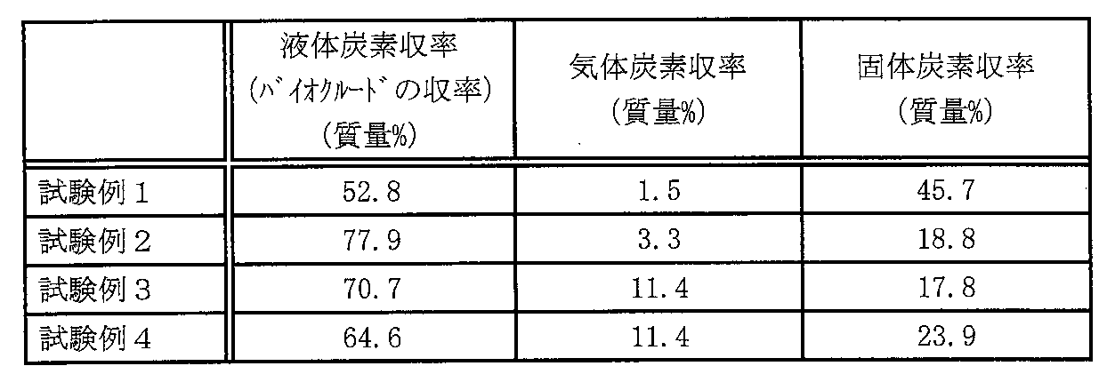
模擬スギをバイオマスとして使用し、混合工程および加溶媒分解工程を行った結果、反応温度を200℃~250℃とすることで、バイオクルードの収率が高くなった。この結果から、反応温度が高い方が、加溶媒分解反応が進行し易くなる傾向が認められた。その一方で、図5の熱重量分析の結果に示すように、300℃の条件では熱分解反応が起こることで、バイオクルードの収率を低下させたものと考えられた。
〈スギチップを使用した加溶媒分解反応の反応時間の検証〉
表3に示す割合でスギチップ、グアイアコール、水および酢酸を混合し(混合工程)、試験例1~4の場合と同様に加溶媒分解反応を行った(加溶媒分解工程)。反応条件は、試験例5~7について反応温度を250℃に固定、反応時間は1時間~4時間とした。
表3に示す割合でスギチップ、グアイアコール、水および酢酸を混合し(混合工程)、試験例1~4の場合と同様に加溶媒分解反応を行った(加溶媒分解工程)。反応条件は、試験例5~7について反応温度を250℃に固定、反応時間は1時間~4時間とした。

反応終了後は、オートクレーブを自然冷却して生成物を取り出し、試験例1~4の場合と同様に、液体生成物、気体生成物および固体生成物の炭素収率(質量%)を算出した。また、液体生成物については、測定装置としてゲル浸透クロマトグラフィー(Gel Permeation Chromatography:GPC)を使用し、分子量を質量%で測定して、分子量が1000未満の液体生成物の収率を算出した。結果を表4に示す。

結果として、加溶媒分解反応の反応時間を長くすることで、バイオクルードの収率が上昇した(表4)。また、分子量1000未満のバイオクルードの収率が増加したことから、反応時間を長くすることで、分解反応によるバイオクルードの低分子量化が進行することがわかった(表4)。
〈パーム核殻を使用した加溶媒分解反応の反応温度および反応時間の検証〉
表5に示す割合でPKS、グアイアコール、水および酢酸を混合し(混合工程)、試験例1~4の場合と同様に加溶媒分解反応を行った(加溶媒分解工程)。なお、PKSは、チップ化する前の未粉砕品を使用した。試験例8~11の反応温度および反応時間は、表5に示すとおりとした。
表5に示す割合でPKS、グアイアコール、水および酢酸を混合し(混合工程)、試験例1~4の場合と同様に加溶媒分解反応を行った(加溶媒分解工程)。なお、PKSは、チップ化する前の未粉砕品を使用した。試験例8~11の反応温度および反応時間は、表5に示すとおりとした。

反応終了後は、オートクレーブを自然冷却して生成物を取り出し、試験例5~7の場合と同様に、液体生成物、気体生成物および固体生成物の炭素収率(質量%)を算出した。また、GPCを使用し、分子量を質量%で測定して、分子量が1000未満の液体生成物の収率を算出した。結果を表6に示す。

バイオマスとしてPKSを使用した場合、反応温度を250℃まで高めることで、バイオクルードの収率が向上した(試験例8、10)。しかし、反応温度を250℃とした場合、反応時間を2時間から4時間まで伸ばしても、バイオクルードの収率はやや高くなると共に、低分子量化がやや進行するにとどまった。
試験例5~7および試験例9~11の結果から、スギとPKSでは、加溶媒分解反応の反応時間を長くした場合における液化および低分子化の進行が異なることが確かめられた。
〈バイオマスの粉砕による液化および低分子量化の検証〉
木質バイオマスの細胞壁は、植物ごとに特徴的な構造体をなしている。また、セルロースの最小単位であるセルロース結晶性微繊維は、数十本のグルカン分子が同一方向に並び水素結合する束状の会合体であり、さらにその会合体の周りをヘミセルロースがまつわりついて結束されている。そのため、セルロース結晶の結晶領域内には水分子が入り込む余地が少なく、加溶媒分解作用を受けにくいことが植物生理・構造学の世界では知られている。すなわち、単に植物細胞内に有機酸等の弱酸水溶液を供給することで、加溶媒分解反応を進行させることは、容易ではない。
木質バイオマスの細胞壁は、植物ごとに特徴的な構造体をなしている。また、セルロースの最小単位であるセルロース結晶性微繊維は、数十本のグルカン分子が同一方向に並び水素結合する束状の会合体であり、さらにその会合体の周りをヘミセルロースがまつわりついて結束されている。そのため、セルロース結晶の結晶領域内には水分子が入り込む余地が少なく、加溶媒分解作用を受けにくいことが植物生理・構造学の世界では知られている。すなわち、単に植物細胞内に有機酸等の弱酸水溶液を供給することで、加溶媒分解反応を進行させることは、容易ではない。
セルロース結晶性微繊維のような高次構造では、グルカン1分子は小さいが、グルカンの各分子がずれながら束ねられているので、繊維長の全長は大きくなっている。よって、木質バイオマスに対して機械的な破砕操作を行うことで、セルロース結晶性微繊維の構造を破壊すること、加溶媒分解に対して効果的と考えられる。そこで、木質バイオマスとしてスギおよびパーム核殻を使用し、これらを粉砕することによるバイオクルードの収率や低分子量化への影響を、以下のとおり検証した。
(スギを使用した検証)
上記したように、遊星ボールミルで粉砕後に篩分けを行ったスギチップ(篩い分けを行って75μmと106μmの篩の間に入ったもの)をバイオマスとしたものを試験例12、遊星ボールミルで粉砕しないチップ状の国産スギをバイオマスとしたものを試験例13とした。表7に示す割合でスギ、グアイアコール、水および酢酸を混合し(混合工程)、試験例1~4の場合と同様に加溶媒分解反応を行った(加溶媒分解工程)。試験例12、13の反応温度は200℃、反応時間は1時間とした。
上記したように、遊星ボールミルで粉砕後に篩分けを行ったスギチップ(篩い分けを行って75μmと106μmの篩の間に入ったもの)をバイオマスとしたものを試験例12、遊星ボールミルで粉砕しないチップ状の国産スギをバイオマスとしたものを試験例13とした。表7に示す割合でスギ、グアイアコール、水および酢酸を混合し(混合工程)、試験例1~4の場合と同様に加溶媒分解反応を行った(加溶媒分解工程)。試験例12、13の反応温度は200℃、反応時間は1時間とした。
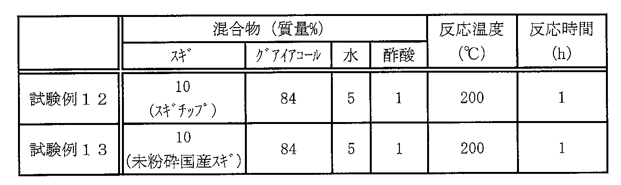
反応終了後は、オートクレーブを自然冷却して生成物を取り出し、試験例5~7の場合と同様に、液体生成物、気体生成物および固体生成物の炭素収率(質量%)を算出した。結果を表8に示す。
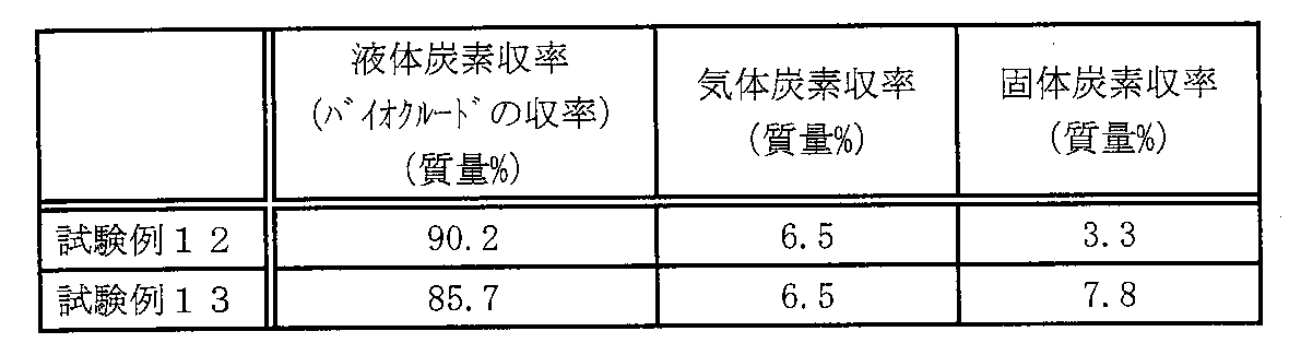
バイオマスとしてスギを用いた場合、スギを粉砕することにより、バイオクルードの収率が高くなった(表8)。
(PKSを使用した検証)
上記したように遊星ボールミルで粉砕後に篩分けを行ったPKSチップ(篩い分けを行って75μmと106μmの篩の間に入ったもの)をバイオマスとしたものを試験例15、16、18とし、未粉砕のPKSを使用した試験例14、17として、バイオクルードの収率および低分子量化について比較した。表9に示す割合で、PKS、グアイアコール、水および酢酸を混合し(混合工程)、試験例1~4の場合と同様に加溶媒分解反応を行った(加溶媒分解工程)。試験例14~16の反応温度は250℃、反応時間は2時間とした。また、試験例17、18の反応温度は250℃、反応時間は0.5時間とした。
上記したように遊星ボールミルで粉砕後に篩分けを行ったPKSチップ(篩い分けを行って75μmと106μmの篩の間に入ったもの)をバイオマスとしたものを試験例15、16、18とし、未粉砕のPKSを使用した試験例14、17として、バイオクルードの収率および低分子量化について比較した。表9に示す割合で、PKS、グアイアコール、水および酢酸を混合し(混合工程)、試験例1~4の場合と同様に加溶媒分解反応を行った(加溶媒分解工程)。試験例14~16の反応温度は250℃、反応時間は2時間とした。また、試験例17、18の反応温度は250℃、反応時間は0.5時間とした。
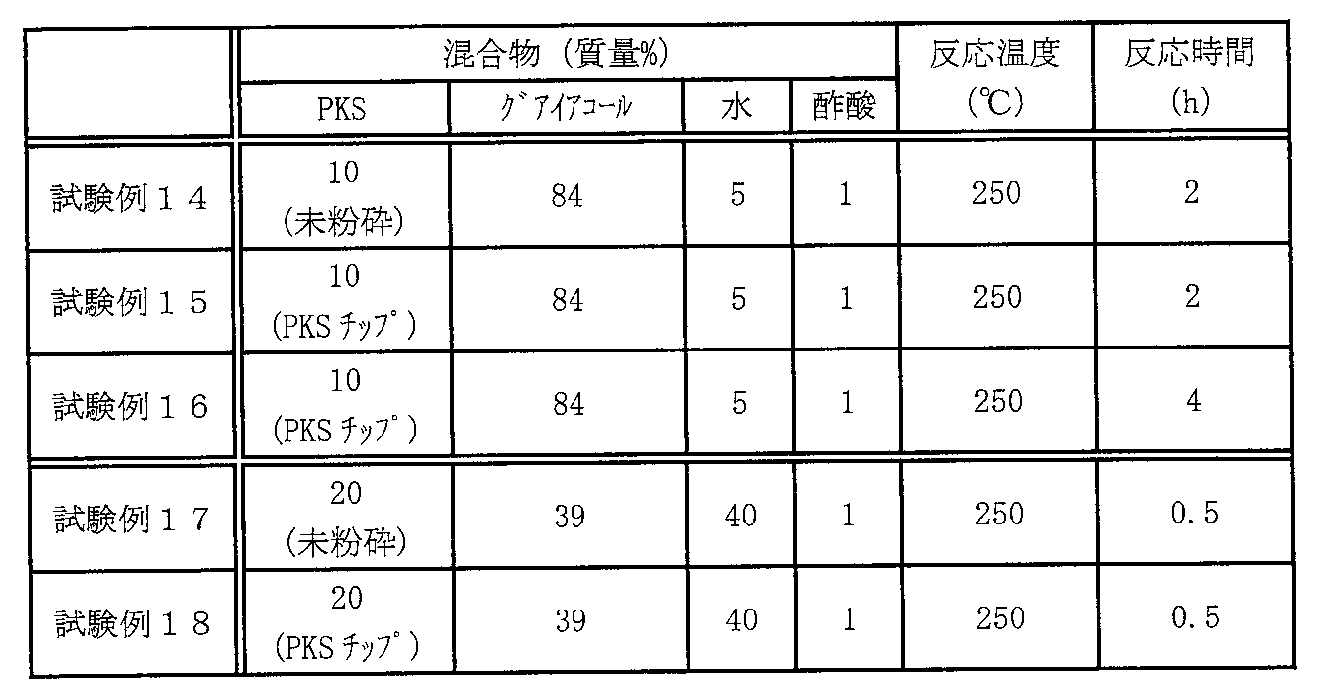
反応終了後は、オートクレーブを自然冷却して生成物を取り出し、試験例5~7の場合と同様に、液体生成物、気体生成物および固体生成物の炭素収率(質量%)を算出した。また、試験例14については、GPCを使用し、分子量を質量%で測定して、分子量が1000未満の液体生成物の収率を算出した。結果を表10に示す。

バイオマスとしてPKSを用いた場合、混合物中の水の含有量が5質量%の場合には、PKSを粉砕することで液化が遅くなり、反応時間を長くすることでバイオクルードの収率を上げることが可能となった(試験例14~16)。ただし、混合物中の水の含有量を40質量%とすることで、PKSを粉砕することによりバイオクルードの収率が高くなった(試験例17、18)。
後に示す試験例32のように、PKSの場合には混合物中の水の含有量を40質量%とすることで、バイオクルードの収率が上がるのである。すなわち、スギやPKSのいずれの場合も、液化が十分に進む水の仕込み量とする条件であれば、バイオマスを粉砕することで液化が促進され、バイオクルードの収率が上がることを確認することができた。
本実施例における加溶媒分解の技術では、セルロースの構造体を崩すためにグアイアコール等の含酸素芳香族化合物溶媒が用いられる。含酸素芳香族化合物溶媒は、植物の構造強度を担うリグニンを溶解する能力を持つ一方、水への溶解度が高い。従って、含酸素芳香族化合物溶媒は、リグニンを溶解することで植物細胞壁を破壊しながら有機酸等の弱酸水溶液を細胞内へ供給することで、セルロースやヘミセルロースの酸加水分解を進めている。
この場合において、加溶媒分解は木質バイオマスの植物構造に依存してその作用機構が異なり、加溶媒分解の最適条件は大きく異なってくる。例えば、スギチップを加溶媒分解する場合には、溶媒中の水の濃度は低くても酸溶媒分解を進行させることができるのに対して、PKSを用いた場合には溶媒中の水の濃度はスギチップの場合よりも高くすることが重要となる。
試験例12と13を対比すると、微粒子に破砕されたスギチップの加溶媒分解では、溶媒中の水濃度が低くても酸加水分解が進行したが、その機構は以下のようなものであると予想される。すなわち、スギチップに含酸素芳香族化合物を含む溶媒が供給された時、スギチップはこの溶媒に溶解していた水を選択的に細胞へ吸収する構造を持っていたと想定される。溶媒と接触したスギチップの細胞壁が、水との水和性または親和性が強い構造を持っていたので、少量の水の添加であっても水が吸収されることにより溶媒から水が分離して、スギチップの細胞内に水相が出現し、ここで酢酸がpH2~3程度に解離することで、セルロースやヘミセルロースの加溶媒分解が進行したものと理解できる。バイオマスとしてスギの場合は形成層が利用されるが、スギは根から吸収された栄養分を含む水分が導管を伝って形成層に効率的に輸送される機構を持っている。この高次構造としての導管が、含酸素芳香族化合物を含む溶媒と直接接触していない細胞へ、水を効率的に輸送配分したものと考えられる。
〈混合物中の各原料の含有量の違いによるバイオクルードの収率の検証〉
本実施例では、バイオマスとして模擬スギまたは未粉砕のPKSを使用し、バイオマス、グアイアコール、水および酢酸の各原料の含有量を変えてバイオクルードを製造し、含有量の違いによるバイオクルードの収率について検証した。
本実施例では、バイオマスとして模擬スギまたは未粉砕のPKSを使用し、バイオマス、グアイアコール、水および酢酸の各原料の含有量を変えてバイオクルードを製造し、含有量の違いによるバイオクルードの収率について検証した。
(模擬スギを使用した検証)
表11に示す割合で模擬スギ、グアイアコール、水および酢酸を混合し(混合工程)、試験例1~4の場合と同様に加溶媒分解反応を行った(加溶媒分解工程)。試験例19~25において、反応温度は200℃とし、反応時間は1時間とした。
表11に示す割合で模擬スギ、グアイアコール、水および酢酸を混合し(混合工程)、試験例1~4の場合と同様に加溶媒分解反応を行った(加溶媒分解工程)。試験例19~25において、反応温度は200℃とし、反応時間は1時間とした。
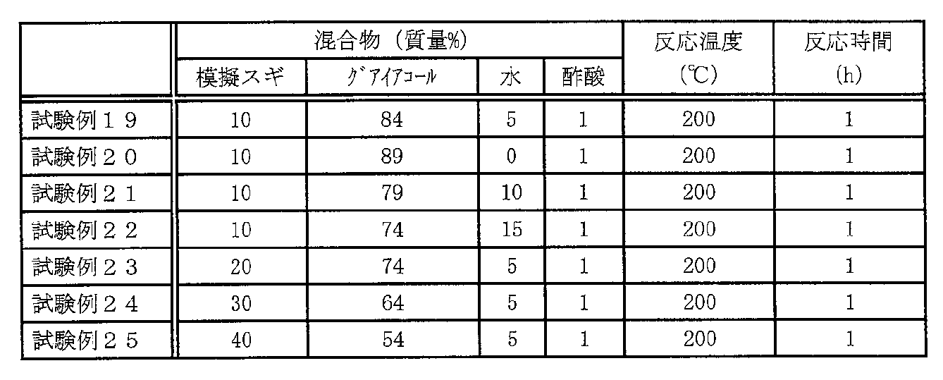
反応終了後は、オートクレーブを自然冷却して生成物を取り出し、試験例1~4の場合と同様に、液体生成物、気体生成物および固体生成物の炭素収率(質量%)を算出した。結果を表12に示す。

模擬スギの含有量を10質量%とした条件において、水を含まない場合には、バイオクルードの収率は低い結果となったが(試験例19、20)、混合物中の水を5質量%以上とすることで、バイオクルードの収率が90質量%前後まで上昇した(試験例19、21、22)。なお、混合物中の水は5質量%より増やしても、バイオクルードの収率はほぼ変わらなかった。また、バイオマスとして模擬スギの含有量を10質量%から30質量%まで増やしても、バイオクルードの収率を90質量%以上の高い収率に維持することができた(試験例19、23、24)。
ただし、模擬スギの含有量を40質量%とした場合には、バイオクルードの収量が低下し、固体生成物の収量が増加した(試験例25)。この結果から、バイオマスの含有量を増やしすぎると、それに応じてバイオマスに対する混合物中のグアイアコールや酢酸の含有量が少なくなることで、加溶媒分解反応が十分に進行しないことが予想された。ただし、試験例9、10の結果からすれば、反応時間を長くすることで、バイオクルードの収量を増加させることは可能と考えられた。
(PKSを使用した検証)
表13に示す割合で未粉砕のPKS、グアイアコール、水および酢酸を混合し(混合工程)、試験例1~4の場合と同様に加溶媒分解反応を行った(加溶媒分解工程)。試験例26~32において、反応温度は250℃とし、反応時間は2時間とした。
表13に示す割合で未粉砕のPKS、グアイアコール、水および酢酸を混合し(混合工程)、試験例1~4の場合と同様に加溶媒分解反応を行った(加溶媒分解工程)。試験例26~32において、反応温度は250℃とし、反応時間は2時間とした。
また、表13には、混合物におけるPKSに対するヒドロニウムイオン(H3O+:プロトンの1水和物)のモル数を示す。これは、加溶媒分解反応における触媒となるプロトン量を比較する目安となるものである。混合物中の水を増やすと、酢酸等の有機酸の解離量が増えるため、触媒作用のあるプロトンが増え、加溶媒分解反応が進みやすくなると考えられる。

反応終了後は、オートクレーブを自然冷却して生成物を取り出し、試験例5~7の場合と同様に、液体生成物、気体生成物および固体生成物の炭素収率(質量%)を算出した。また、GPCを使用し、分子量を質量%で測定して、分子量が1000未満の液体生成物の収率を算出した。結果を表14に示す。

バイオマスとして未粉砕のPKSを使用した場合には、PKSの含有量を増やすとバイオクルードの収率および低分子量化がやや低下する傾向が認められた(試験例26~28)。また、水の含有量を15質量%以上にすることで、バイオクルードの収率が約90%となり、分子量1000未満のバイオクルードの収率が50質量%を越え、高い収率と低分子量化が認められた(試験例29~32)。
PKSは、含酸素芳香族化合物を含む溶媒への溶解性が高いので、粉砕して微細化しないままで、バイオクルードの製造を行った。その結果、低分子量化に関しては、約55質量%が上限であり(試験例30)、低分子量化の限度が示された。これは、PKSにおけるリグニンの組成値までしか分解が進行せず、セルロースやヘミセルロースの分解が進行していないようにも受け取れる結果であった。この結果は、パルプ製造で見られる結果と類似している。おそらく、リグニンが取り除かれた後であっても、セルロースやヘミセルロースの細胞壁での堆積状態が、水の拡散を阻害する形態をとっているものと予想される。PKSは、リグニンの含有量が多く、強度が高いので、PKSを粉砕するにはそれなりの技術が要求されると考えられる。ただし、PKSを粉砕した後は、セルロースおよびヘミセルロースの分解が進行することが期待され、より低分子量化が進むことが予想される。
一方、PKSは粉砕しなくても容易に含酸素芳香族化合物を含む溶媒に溶解するが、加溶媒分解に際して要求される水分量が大きいことが分かった(試験例29~32)。含酸素芳香族化合物を含む溶媒としてグアイアコールを用いた場合では、この溶媒は水を10質量%程度まで溶解するが、混合物中の水の含有量を、この溶解度以上にすると10質量%以下のときに比べて、バイオクルードの収率が高くなった(試験例29~32)。
混合物中の水の含有量が、含酸素芳香族化合物を含む溶媒の水の溶解度以下の場合は、反応場に水が形成されない。ただし、この溶解度以上に混合物が水を含有する場合は、混合物は2液相となり水相が形成される。水相が形成する前は、酢酸が水に溶解していないことで酢酸が解離状態でなかったのに対して、水相が形成された後は、水相において酢酸が解離できるようになったことで、加溶媒分解がより進行し易くなったことが予想される。PKSの表面は、撥水性の性状を持っているので、スギチップのように細胞への水の選択的な吸収をしないので、加溶媒分解反応を進めるためには、PKSの細胞外で溶媒の2液相分離が重要であったものと推測される。さらに、このように高次構造において、PKSのように撥水性の表面を持つ木質バイオマスでは、細胞壁内への水の拡散が阻害されるために、加溶媒分解反応を進めるには含酸素芳香族化合物を含む溶媒への加水量を上げることが必要になっていたものと考えられる。なお、原料に対する酢酸量が同じだとしても、水の割合を増やすと加溶媒分解反応の反応系内で解離プロトン総量が増えるので(試験例29~32)、いわゆるcat/oilが大きくなることで加溶媒分解による低分子量化が進むものと考えられる。一方で、水の割合が少ないと、水が含酸素芳香族化合物を含む溶媒に溶解することで、酢酸が解離し易い水層が無くなり、低分子量化が進まないものと考えられる。
ここで、cat/oilは、バッチ型反応器内での原料(kg/m3)と触媒(kg/m3)の存在比、流通型反応器への原料供給量(kg/hr)と触媒供給量(kg/hr)の比、または、Catalyst触媒(kg)とoil原料(kg)の存在比を表すものである。例えば、反応器内に触媒量を多く存在させると、反応速度が大きくなる。cat/oilというパラメーターは、バイオクルードを炭化水素に転換させる、流動接触分解プロセスにおいて、主要な反応条件となっている。
[炭化水素の製造]
〈ゼオライト触媒の格子定数が与える炭化水素の収率への影響〉
炭化水素を製造するにあたり、木質バイオマスを原料とする場合、木質バイオマスの酸素含有量は50質量%程度である。そのため、効率的に酸素を取り除いて炭化水素を製造すれば、炭化水素の収率は原料に対して50質量%になる。一般的には、バイオクルードを脱酸素するに際して、一酸化炭素(CO)や二酸化炭素(CO2)が副生してしまい、その分炭化水素の収率は低下することとなる。理想的には、水素移行反応によって生成する水素によって、バイオクルードから脱酸素すれば、水が生成してCOやCO2は生成しないため、炭化水素の収率は50質量%に近い値が得られるはずである。
〈ゼオライト触媒の格子定数が与える炭化水素の収率への影響〉
炭化水素を製造するにあたり、木質バイオマスを原料とする場合、木質バイオマスの酸素含有量は50質量%程度である。そのため、効率的に酸素を取り除いて炭化水素を製造すれば、炭化水素の収率は原料に対して50質量%になる。一般的には、バイオクルードを脱酸素するに際して、一酸化炭素(CO)や二酸化炭素(CO2)が副生してしまい、その分炭化水素の収率は低下することとなる。理想的には、水素移行反応によって生成する水素によって、バイオクルードから脱酸素すれば、水が生成してCOやCO2は生成しないため、炭化水素の収率は50質量%に近い値が得られるはずである。
本実施例では、バイオクルードを原料として流動接触分解により炭化水素を製造する際に用いるゼオライト触媒の格子定数に着目し、この格子定数を変えることで炭化水素の収率を向上させることができるか、検証した。
(流動接触分解工程)
試験例12で得たバイオクルードを原料とし、ゼオライト触媒および水素供与体としてエイコサンを用いて流動接触分解し、炭化水素を製造した。流動接触分解するための反応器として、ASTM D3907-92に準拠した固定床流通式反応器を用い、触媒としてFAU型ゼオライトを含有する工業用RFCC平衡触媒を用いた。工業用RFCC平衡触媒のUCS値(ゼオライト格子定数)は、試験例A~Dにおいて24.27Å(2.427nm)~24.40Å(2.440nm)とした。また、工業用RFCC平衡触媒と、バイオクルードおよび水素供与体の合計質量との比はCat/Oil=3とし、反応器に充填された触媒に対する原料供給量の重量比(Weight Hourly Space Velocity:WHSV)はWHSV=16-1、流動接触分解反応の反応温度は500℃とした。なお、実験方法はASTM D5154-10に規定の方法に従って行った。
試験例12で得たバイオクルードを原料とし、ゼオライト触媒および水素供与体としてエイコサンを用いて流動接触分解し、炭化水素を製造した。流動接触分解するための反応器として、ASTM D3907-92に準拠した固定床流通式反応器を用い、触媒としてFAU型ゼオライトを含有する工業用RFCC平衡触媒を用いた。工業用RFCC平衡触媒のUCS値(ゼオライト格子定数)は、試験例A~Dにおいて24.27Å(2.427nm)~24.40Å(2.440nm)とした。また、工業用RFCC平衡触媒と、バイオクルードおよび水素供与体の合計質量との比はCat/Oil=3とし、反応器に充填された触媒に対する原料供給量の重量比(Weight Hourly Space Velocity:WHSV)はWHSV=16-1、流動接触分解反応の反応温度は500℃とした。なお、実験方法はASTM D5154-10に規定の方法に従って行った。
流動接触分解工程により得られた生成物を以下のように分析した。まず、触媒槽を通過した反応生成物を氷浴で冷却し、気液分離した後に、気体生成物および液体生成物をそれぞれ回収した。そして、気体の回収は水上置換で行った。気体生成物中に含まれる水素、一酸化炭素、および二酸化炭素は熱伝導度型検出器付ガスクロマトグラフィー(島津製作所製、GC-8A)で分析し、炭化水素は水素炎イオン化型検出器付ガスクロマトグラフィー(島津製作所製、GC-2014)で分析した。また、液体生成物中の炭化水素と含酸素化合物は水素炎イオン化型検出器付ガスクロマトグラフィー(島津製作所製、GC-2014)とガスクロマトグラフ質量分析計(島津製作所製、GCMS-QP2010 Plus)を用いて分析した。ここで、含酸素化合物には一酸化炭素、二酸化炭素および水は含まれない。
次に、コークの生成量は反応前後での触媒槽の重量変化から求め、その成分はNCアナライザー(住化分析センター製、SUMIGRAPH NC-1000)を用いて分析した。ガスクロマトグラフィーによって検出できなかった成分をその他とした。なお、液体生成物中に水が含まれることを目視で確認しているが、ガスクロマトグラフィーでは定量が困難であるため、水はその他に含めることとした。さらに、その他には未分解の高分子含酸素成分も含まれると考えられる。流動接触分解工程により得られた反応生成物の組成を分析した結果を、表15に示す。
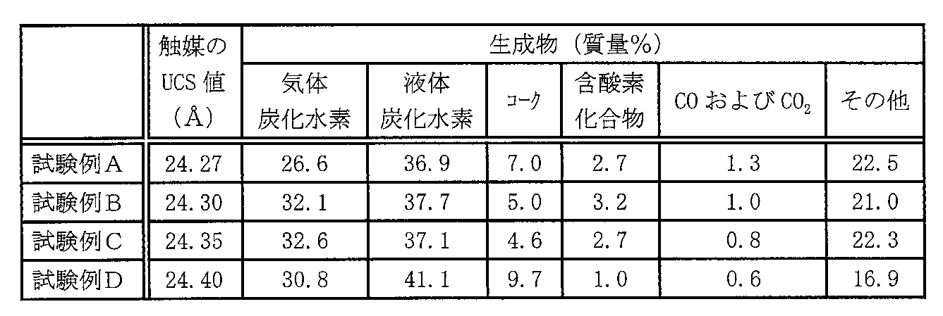
結果として、水素移行反応性の高い触媒、すなわちUCS値の大きい触媒で脱酸素することで、含酸素化合物、一酸化炭素および二酸化炭素の生成量が低下し、炭化水素の収率が高くなることがわかった(表15)。この結果から、バイオクルードを流動接触分解した際に、一酸化炭素や二酸化炭素が副生して脱酸素する割合が低下し、水素移行反応による影響で炭化水素の収率が高くなったと考えられる。
[まとめ]
以上のように、本発明のバイオクルードの製造方法であれば、バイオマスを原料として加溶媒分解することで、高収率でバイオクルードを製造することができる。また、本発明の炭化水素の製造方法であれば、一酸化炭素および二酸化炭素の生成を抑制しつつ、バイオクルードを水素化脱酸素することで、高収率で炭化水素を製造することができる。
以上のように、本発明のバイオクルードの製造方法であれば、バイオマスを原料として加溶媒分解することで、高収率でバイオクルードを製造することができる。また、本発明の炭化水素の製造方法であれば、一酸化炭素および二酸化炭素の生成を抑制しつつ、バイオクルードを水素化脱酸素することで、高収率で炭化水素を製造することができる。
1 バイオクルードの製造装置
2 反応器
3 蒸留塔
4a、4b、4c、4d 導入ライン
5 導入ライン
6a、6b 排出ライン
7a、7b、7c、7d、7e、7f、7g バルブ
10 原料貯蔵タンク
20 原料供給管
21 バルブ
30 ライザー反応管
40 再生塔
50 蒸留塔
100 炭化水素の製造装置
200 炭化水素の製造装置
210 原料貯蔵タンク
211 バイオクルード貯蔵タンク
212 水素供与体貯蔵タンク
220 原料供給管
221 バルブ
222 バイオクルード供給管
223 水素供与体供給管
224 混合供給管
300 炭化水素の製造装置
310 原料貯蔵タンク
311 バイオクルード貯蔵タンク
312 水素供与体貯蔵タンク
320 原料供給管
321a、321b バルブ
322 バイオクルード供給管
323 水素供与体供給管
2 反応器
3 蒸留塔
4a、4b、4c、4d 導入ライン
5 導入ライン
6a、6b 排出ライン
7a、7b、7c、7d、7e、7f、7g バルブ
10 原料貯蔵タンク
20 原料供給管
21 バルブ
30 ライザー反応管
40 再生塔
50 蒸留塔
100 炭化水素の製造装置
200 炭化水素の製造装置
210 原料貯蔵タンク
211 バイオクルード貯蔵タンク
212 水素供与体貯蔵タンク
220 原料供給管
221 バルブ
222 バイオクルード供給管
223 水素供与体供給管
224 混合供給管
300 炭化水素の製造装置
310 原料貯蔵タンク
311 バイオクルード貯蔵タンク
312 水素供与体貯蔵タンク
320 原料供給管
321a、321b バルブ
322 バイオクルード供給管
323 水素供与体供給管
Claims (9)
- バイオマスと、含酸素芳香族化合物を含む溶媒を混合して混合物を得る混合工程と、
前記混合物を190~250℃に加熱して、当該混合物を加溶媒分解する加溶媒分解工程と、
を含む、バイオクルードの製造方法。 - 前記混合物は、ギ酸、酢酸、プロピオン酸または酪酸の少なくともいずれかを含む有機酸を含む、請求項1に記載のバイオクルードの製造方法。
- 前記混合物は水を含む、請求項1または2に記載のバイオクルードの製造方法。
- 前記含酸素芳香族化合物を含む溶媒は、両親媒性の含酸素芳香族化合物であり、
前記混合物は、酢酸または酢酸を主成分とする有機酸を含む、請求項3に記載のバイオクルードの製造方法。 - 前記混合工程の前に、前記バイオマスを粉砕する粉砕工程と、
粉砕後の前記バイオマスを篩分けする篩分け工程と、を含み、
前記混合工程は、前記篩分け工程後のバイオマスを混合する、請求項1~4のいずれかに記載のバイオクルードの製造方法。 - 前記混合物中の前記バイオマスの含有量が10~30質量%であり、水の含有量が5~40質量%である、請求項3~5のいずれかに記載のバイオクルードの製造方法。
- バイオクルード中の分子量1000未満のバイオクルードの含有量が、38質量%以上である、請求項1~6のいずれかに記載のバイオクルードの製造方法。
- 請求項1~7のいずれかに記載のバイオクルードの製造方法により得た前記バイオクルードを、水素供与体を用いて流動接触分解する流動接触分解工程を含む、炭化水素の製造方法。
- 前記流動接触分解に、ゼオライト格子定数が24.20Å~24.45Åのゼオライトを触媒として用いる、請求項8に記載の炭化水素の製造方法。
Applications Claiming Priority (2)
| Application Number | Priority Date | Filing Date | Title |
|---|---|---|---|
| JP2018146408A JP2020019912A (ja) | 2018-08-03 | 2018-08-03 | 炭化水素の製造方法およびバイオクルードの製造方法 |
| JP2018-146408 | 2018-08-03 |
Publications (1)
| Publication Number | Publication Date |
|---|---|
| WO2020026883A1 true WO2020026883A1 (ja) | 2020-02-06 |
Family
ID=69231738
Family Applications (1)
| Application Number | Title | Priority Date | Filing Date |
|---|---|---|---|
| PCT/JP2019/028774 Ceased WO2020026883A1 (ja) | 2018-08-03 | 2019-07-23 | 炭化水素の製造方法およびバイオクルードの製造方法 |
Country Status (2)
| Country | Link |
|---|---|
| JP (1) | JP2020019912A (ja) |
| WO (1) | WO2020026883A1 (ja) |
Citations (7)
| Publication number | Priority date | Publication date | Assignee | Title |
|---|---|---|---|---|
| JPS6317961A (ja) * | 1986-07-10 | 1988-01-25 | Oji Paper Co Ltd | リグノセルロ−ス物質の溶液調製方法 |
| JPH05179253A (ja) * | 1991-12-27 | 1993-07-20 | Hisaka Works Ltd | 木粉の液化方法および装置 |
| JPH0959519A (ja) * | 1995-08-18 | 1997-03-04 | Sumitomo Forestry Co Ltd | リグノセルロース物質の加熱変性による樹脂原料組成 物の製造法 |
| JP2010500464A (ja) * | 2006-08-16 | 2010-01-07 | バイオイーコン インターナショナル ホールディング エヌ.ブイ. | 含酸素化合物の流動接触分解法 |
| JP2016069577A (ja) * | 2014-09-30 | 2016-05-09 | Jx日鉱日石エネルギー株式会社 | 木質バイオマススラリー、木質バイオマス加水分解生成物、有機化合物の製造方法 |
| JP2017088662A (ja) * | 2015-11-04 | 2017-05-25 | 株式会社ユーグレナ | 炭化水素の製造方法 |
| WO2018147281A1 (ja) * | 2017-02-07 | 2018-08-16 | 国立大学法人信州大学 | 炭化水素の製造方法、その製造装置、その製造システム、及び、バイオクルードの製造方法 |
-
2018
- 2018-08-03 JP JP2018146408A patent/JP2020019912A/ja active Pending
-
2019
- 2019-07-23 WO PCT/JP2019/028774 patent/WO2020026883A1/ja not_active Ceased
Patent Citations (7)
| Publication number | Priority date | Publication date | Assignee | Title |
|---|---|---|---|---|
| JPS6317961A (ja) * | 1986-07-10 | 1988-01-25 | Oji Paper Co Ltd | リグノセルロ−ス物質の溶液調製方法 |
| JPH05179253A (ja) * | 1991-12-27 | 1993-07-20 | Hisaka Works Ltd | 木粉の液化方法および装置 |
| JPH0959519A (ja) * | 1995-08-18 | 1997-03-04 | Sumitomo Forestry Co Ltd | リグノセルロース物質の加熱変性による樹脂原料組成 物の製造法 |
| JP2010500464A (ja) * | 2006-08-16 | 2010-01-07 | バイオイーコン インターナショナル ホールディング エヌ.ブイ. | 含酸素化合物の流動接触分解法 |
| JP2016069577A (ja) * | 2014-09-30 | 2016-05-09 | Jx日鉱日石エネルギー株式会社 | 木質バイオマススラリー、木質バイオマス加水分解生成物、有機化合物の製造方法 |
| JP2017088662A (ja) * | 2015-11-04 | 2017-05-25 | 株式会社ユーグレナ | 炭化水素の製造方法 |
| WO2018147281A1 (ja) * | 2017-02-07 | 2018-08-16 | 国立大学法人信州大学 | 炭化水素の製造方法、その製造装置、その製造システム、及び、バイオクルードの製造方法 |
Also Published As
| Publication number | Publication date |
|---|---|
| JP2020019912A (ja) | 2020-02-06 |
Similar Documents
| Publication | Publication Date | Title |
|---|---|---|
| Wang et al. | The effects of temperature and catalysts on the pyrolysis of industrial wastes (herb residue) | |
| Misson et al. | Pretreatment of empty palm fruit bunch for production of chemicals via catalytic pyrolysis | |
| JP6882176B2 (ja) | 蒸解廃液およびその使用 | |
| RU2451712C2 (ru) | Способ получения сжиженного горючего с использованием биомассы в качестве сырья | |
| CN102947421B (zh) | 生物燃料的生产方法 | |
| CA2814997C (en) | Production of renewable bio-gasoline | |
| Heeres et al. | Synthesis of bio-aromatics from black liquors using catalytic pyrolysis | |
| US8558043B2 (en) | Modular biomass treatment unit | |
| US9534174B2 (en) | Fast catalytic pyrolysis with recycle of side products | |
| WO2019002683A1 (en) | METHOD FOR INCREASING THE SELECTIVITY OF PETROLEUM DISTILLATE AND MEDIUM DISTILLATE IN CATALYTIC CRACKING | |
| CA2798714A1 (en) | Hydroprocessing of pyrolysis oil and its use as a fuel | |
| BR112015030837B1 (pt) | Processo de bio-refino | |
| CA2811646A1 (en) | Production of renewable bio-distillate | |
| US20160186067A1 (en) | Methods and systems for processing cellulosic biomass | |
| US20130025187A1 (en) | Processes for converting lignocellulosics to reduced acid pyrolysis oil | |
| JP2018501945A (ja) | 触媒急速熱分解の生成物から一酸化炭素を回収する改良された方法 | |
| EP3929268B1 (en) | Multistage process with hydrothermal liquefaction | |
| WO2015092143A1 (en) | Intergrated pyrolysis process | |
| WO2020026883A1 (ja) | 炭化水素の製造方法およびバイオクルードの製造方法 | |
| WO2018147281A1 (ja) | 炭化水素の製造方法、その製造装置、その製造システム、及び、バイオクルードの製造方法 | |
| US20160184797A1 (en) | Methods and systems for processing cellulosic biomass | |
| US20160186068A1 (en) | Methods and systems for processing cellulosic biomass | |
| Mathanker | Hydrothermal liquefaction of lignocellulosic biomass to produce biofuels | |
| RU2575707C2 (ru) | Способы производства биотоплива |
Legal Events
| Date | Code | Title | Description |
|---|---|---|---|
| 121 | Ep: the epo has been informed by wipo that ep was designated in this application |
Ref document number: 19843740 Country of ref document: EP Kind code of ref document: A1 |
|
| NENP | Non-entry into the national phase |
Ref country code: DE |
|
| 122 | Ep: pct application non-entry in european phase |
Ref document number: 19843740 Country of ref document: EP Kind code of ref document: A1 |