WO2020022463A1 - 蓄電装置及び温度推定方法 - Google Patents
蓄電装置及び温度推定方法 Download PDFInfo
- Publication number
- WO2020022463A1 WO2020022463A1 PCT/JP2019/029325 JP2019029325W WO2020022463A1 WO 2020022463 A1 WO2020022463 A1 WO 2020022463A1 JP 2019029325 W JP2019029325 W JP 2019029325W WO 2020022463 A1 WO2020022463 A1 WO 2020022463A1
- Authority
- WO
- WIPO (PCT)
- Prior art keywords
- power storage
- storage element
- current
- temperature
- unit
- Prior art date
- Legal status (The legal status is an assumption and is not a legal conclusion. Google has not performed a legal analysis and makes no representation as to the accuracy of the status listed.)
- Ceased
Links
Images




Classifications
-
- H—ELECTRICITY
- H01—ELECTRIC ELEMENTS
- H01M—PROCESSES OR MEANS, e.g. BATTERIES, FOR THE DIRECT CONVERSION OF CHEMICAL ENERGY INTO ELECTRICAL ENERGY
- H01M10/00—Secondary cells; Manufacture thereof
- H01M10/42—Methods or arrangements for servicing or maintenance of secondary cells or secondary half-cells
- H01M10/48—Accumulators combined with arrangements for measuring, testing or indicating the condition of cells, e.g. the level or density of the electrolyte
-
- G—PHYSICS
- G01—MEASURING; TESTING
- G01R—MEASURING ELECTRIC VARIABLES; MEASURING MAGNETIC VARIABLES
- G01R31/00—Arrangements for testing electric properties; Arrangements for locating electric faults; Arrangements for electrical testing characterised by what is being tested not provided for elsewhere
- G01R31/36—Arrangements for testing, measuring or monitoring the electrical condition of accumulators or electric batteries, e.g. capacity or state of charge [SoC]
- G01R31/389—Measuring internal impedance, internal conductance or related variables
-
- H—ELECTRICITY
- H02—GENERATION; CONVERSION OR DISTRIBUTION OF ELECTRIC POWER
- H02J—ELECTRIC POWER NETWORKS; CIRCUIT ARRANGEMENTS OR SYSTEMS FOR SUPPLYING OR DISTRIBUTING ELECTRIC POWER; SYSTEMS FOR STORING ELECTRIC ENERGY
- H02J7/00—Circuit arrangements for charging or discharging batteries or for supplying loads from batteries
-
- Y—GENERAL TAGGING OF NEW TECHNOLOGICAL DEVELOPMENTS; GENERAL TAGGING OF CROSS-SECTIONAL TECHNOLOGIES SPANNING OVER SEVERAL SECTIONS OF THE IPC; TECHNICAL SUBJECTS COVERED BY FORMER USPC CROSS-REFERENCE ART COLLECTIONS [XRACs] AND DIGESTS
- Y02—TECHNOLOGIES OR APPLICATIONS FOR MITIGATION OR ADAPTATION AGAINST CLIMATE CHANGE
- Y02E—REDUCTION OF GREENHOUSE GAS [GHG] EMISSIONS, RELATED TO ENERGY GENERATION, TRANSMISSION OR DISTRIBUTION
- Y02E60/00—Enabling technologies; Technologies with a potential or indirect contribution to GHG emissions mitigation
- Y02E60/10—Energy storage using batteries
Definitions
- the present invention relates to a power storage device for estimating a temperature of a power storage element and a temperature estimating method.
- Energy storage devices are widely used in uninterruptible power supplies, DC or AC power supplies included in stabilized power supplies, and the like.
- the use of power storage elements in large-scale systems for storing generated power is expanding.
- a power storage system is configured by connecting a plurality of power storage elements in series or in series / parallel.
- the current and voltage of the storage element can be detected relatively easily using a current sensor and a voltage sensor. However, it is difficult to detect the temperature or the amount of heat generated inside the power storage element. Conventionally, for example, a temperature sensor such as a thermistor disposed near the power storage element is used to measure the external temperature of the power storage element, and the measured temperature is used for controlling the power storage element.
- a temperature sensor such as a thermistor disposed near the power storage element is used to measure the external temperature of the power storage element, and the measured temperature is used for controlling the power storage element.
- Patent Document 1 discloses a method for estimating the temperature of a storage element. Specifically, the internal resistance of the storage element obtained by using the AC impedance method, the duration from the start of charge / discharge, the SOC (State ⁇ of ⁇ Charge ⁇ ; state of charge) of the storage element, and the temperature of the storage element The internal heat generation amount is calculated at predetermined time intervals using an internal resistance map showing the relationship with. The power storage element is cooled by the cooling device based on the estimated temperature.
- the AC impedance method requires one measuring device for each storage element. It is difficult to apply the technology described in Patent Literature 1 to a power storage device or a power storage system including a plurality of power storage elements to estimate the temperature of each power storage element.
- An object of the present invention is to provide a power storage device and a temperature estimation method that can easily estimate the temperature of a power storage element.
- a power storage device includes a power storage element, and a management unit that measures a voltage of the power storage element and manages the power storage element. Then, the voltage of the power storage element is measured, the internal resistance of the power storage element is calculated by a DC resistance measurement method using the measured voltage, and the calorific value of the power storage element is calculated based on the internal resistance and the conduction profile. Is estimated.
- a temperature estimation method is a method for estimating a temperature of a power storage element, in which a voltage of the power storage element is measured in a state where a DC current flows through the power storage element, and the measured voltage is used.
- a DC resistance measurement method an internal resistance of the power storage element is calculated, a calorific value in the power storage element is estimated based on the internal resistance and a conduction profile, and a heat conduction simulation is performed based on the calorific value.
- the temperature of the power storage element is estimated.
- the internal resistance of the storage element charged and discharged with direct current can be easily calculated, and the amount of heat generated in the storage element can be easily estimated.
- the temperature of the storage element in the future for example, after several seconds or several minutes
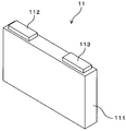
- FIG. 3 is a schematic diagram illustrating an example of an appearance of a power storage module.
- FIG. 3 is a block diagram illustrating an example of a functional configuration of the power storage module according to the first embodiment.
- FIG. 3 is a block diagram illustrating an example of a functional configuration of a current measurement unit and a voltage measurement unit according to the first embodiment.
- FIG. 3 is a schematic diagram illustrating an example of storage contents of a storage unit according to the first embodiment.
- 4 is a flowchart illustrating a procedure of a process for estimating the temperature of the storage cell executed by the BMU according to the first embodiment.
- FIG. 3 is a schematic diagram illustrating an example of an appearance of a power storage module.
- FIG. 3 is a block diagram illustrating an example of a functional configuration of the power storage module according to the first embodiment.
- FIG. 3 is a block diagram illustrating an example of a functional configuration of a current measurement unit and a voltage measurement unit according to the first embodiment.
- FIG. 3 is a
- FIG. 9 is a block diagram illustrating an example of a functional configuration of a current measurement unit and a voltage measurement unit according to a second embodiment.
- 9 is a flowchart illustrating a procedure of a process for estimating a temperature of a power storage cell executed by the BMU according to the second embodiment.
- FIG. 13 is a block diagram illustrating an example of a functional configuration of a power storage module and a battery management device according to a third embodiment.
- the power storage device includes a power storage element, and a management unit that measures a voltage of the power storage element and manages the power storage element.
- the management unit is configured to control a voltage of the power storage element while a DC current flows through the power storage element. Is measured, the internal resistance of the power storage element is calculated by a DC resistance measurement method using the measured voltage, and the amount of heat generated in the power storage element is estimated based on the internal resistance and the energization profile.
- the power storage device includes a power storage element and a management unit.
- the management unit measures the voltage of the power storage element while a DC current flows through the power storage element, and calculates the internal resistance of the power storage element by a DC resistance measurement method.
- the management unit can easily and accurately calculate the internal resistance of the storage element that is frequently charged and discharged by DC.
- the management unit estimates a heat generation amount in the power storage element based on the internal resistance and the energization profile.
- the internal resistance obtained by the DC resistance measurement method is a DC resistance.
- a power storage element is charged and discharged with direct current, so that the heat generation factor of the power storage element is substantially limited to a direct current resistance. For this reason, the calorific value of the storage element can be accurately estimated using the internal resistance of the storage element calculated by the DC resistance measurement method.
- the power storage device may use a predicted power-on profile as the power-on profile to estimate a future heat generation amount in the power storage element.
- a predicted power-on profile as the power-on profile to estimate a future heat generation amount in the power storage element.
- in-situ estimation in-situ estimation
- the management unit provided in the power storage device estimates the near future heat generation using the internal resistance calculated by the DC resistance measurement method, thereby suppressing the deterioration of the power storage element or maintaining the performance of the power storage element. It can be used up in minutes.
- the management unit measures a current flowing through the power storage element in a state where a DC current flows through the power storage element, and obtains an electromotive force of the power storage element obtained according to an SOC of the power storage element, the measured current, and
- the internal resistance of the power storage device may be calculated based on the measured voltage.
- the internal resistance of the storage element can be obtained by a simple calculation using the current and voltage measured in a state where a DC current flows through the storage element and the electromotive force of the storage element.
- the internal resistance is calculated based on the electromotive force according to the SOC, the measured current, and the measured voltage of the power storage element. Is preferred. Such a calculation can be realized by hardware normally provided in a typical power storage device (power storage module) (the power storage device does not require additional hardware).
- the management unit includes a current source connected in parallel to the power storage element, and when the current source applies a first DC current to the power storage element while a DC current flows through the power storage element, the power storage unit Measuring a first voltage of the element, in a state where a DC current flows through the power storage element, when the current source applies a second DC current having a value different from the first DC current to the power storage element, A second voltage of the power storage device may be measured, and an internal resistance of the power storage device may be calculated based on the first voltage and the second voltage.
- the current source the internal resistance of the storage element can be obtained based on the first voltage and the second voltage without using the electromotive force of the storage element and the current flowing through the storage element.
- the management unit may estimate the temperature of the power storage element by performing a heat conduction simulation based on the heat generation amount.
- the temperature of the power storage element can be easily and accurately estimated using the calorific value of the power storage element estimated accurately.
- the management unit includes a storage unit that stores a program, and an operation unit that performs an operation based on the program.
- the storage unit operates on a real-time OS (Operating System) program and operates on the real-time OS.
- a program for calculating the internal resistance, estimating the heating value, and estimating the temperature may be stored.
- the management unit can execute processing with high responsiveness. Therefore, the management unit can estimate the future temperature of the storage element at high speed. If the response is sufficient, the management unit does not need to use the real-time OS.
- the management unit may estimate a future heating value of the power storage element by calculating a heating value using a future current and the internal resistance according to the predicted energization profile. Using the internal resistance of the storage element calculated by the DC resistance measurement method and the future current according to the energization profile, it is possible to accurately estimate the future calorific value of the storage element.
- the management unit may estimate a plurality of types of heat generation based on a plurality of predicted energization profiles.
- the management unit can estimate a plurality of types of temperatures according to the plurality of types of heat values.
- the temperature of the storage element can be estimated without reducing the energization profile to one.
- the storage element may be a reused product (recycled product). Even when the storage element is a reused product, the internal resistance of the storage element can be easily and accurately calculated by the same method, and the temperature of the storage element can be easily and accurately estimated. It is possible to properly grasp the internal resistance and the temperature of the storage element of the reused product and appropriately control the storage element.
- the temperature estimating method is a method of estimating the temperature of the power storage element, in a state where a DC current flows through the power storage element, measuring the voltage of the power storage element, and using a DC resistance measurement method using the measured voltage, By calculating the internal resistance of the storage element, based on the internal resistance and the conduction profile, estimating the amount of heat generated in the storage element, and performing heat conduction simulation based on the generated amount of heat, Estimate the temperature.
- the DC resistance measurement method the internal resistance of the storage element charged and discharged by DC can be easily and accurately calculated. Therefore, it is possible to easily and accurately estimate the amount of heat generated in the storage element, and easily and accurately estimate the temperature of the storage element.
- FIG. 1 is a schematic diagram illustrating an example of the appearance of the storage cell 11.
- the storage cell 11 corresponds to a storage element.
- the storage cell 11 is a secondary battery such as a lithium ion battery.
- the storage cell 11 has a cuboid shape (prismatic shape).
- the storage cell 11 includes a rectangular parallelepiped case 111, a positive terminal 112, and a negative terminal 113. Inside the case 111, a positive electrode, a negative electrode, a separator, and an electrolyte (electrolyte solution) are accommodated.
- the separator is interposed between the positive electrode and the negative electrode.
- the positive electrode, the negative electrode, and the separator have a sheet shape, and are housed in the case 111 as an electrode body obtained by overlapping and winding them.
- the electrode body is not limited to the wound type, and may be a stacked type.
- the positive electrode is connected to the positive terminal 112, and the negative electrode is connected to the negative terminal 113.
- the direction in which the length of the storage cell 11 is the shortest is defined as the thickness direction.
- the shape of the power storage cell 11 may be a shape other than a rectangular parallelepiped, and may be a pouch shape or a cylindrical shape.
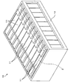
- FIG. 2 is a schematic diagram illustrating an example of the external appearance of the power storage module 10.
- Power storage module 10 corresponds to a power storage device.
- the power storage module 10 includes a plurality of power storage cells 11 connected in series and / or in parallel.
- the power storage module 10 includes a rectangular parallelepiped housing 12 that is an example of a holding member.
- the plurality of power storage cells 11 are arranged in the thickness direction, and are held (stored) in the housing 12.
- the holding member may be formed by a pair of end plates and a plurality of fastening bars connecting the end plates.
- the plurality of power storage cells 11 are connected in series and / or in parallel by a bus bar (not shown).
- the power storage module 10 further includes a BMU (Battery Management Unit) 2.
- BMU2 corresponds to a management unit. In FIG. 2, BMU2 is indicated by a broken line.
- the BMU 2 has a configuration in which various components are arranged on a substrate.
- the BMU 2 manages a power storage cell 11 included in the power storage module 10. Specifically, BMU 2 calculates the SOC of power storage cell 11 by a current integration method.
- the SOC is a ratio of the amount of electricity charged in the storage cell 11 to the full charge capacity of the storage cell 11. Further, the BMU 2 performs a process of estimating the temperature of the storage cell 11.
- FIG. 3 is a block diagram illustrating an example of a functional configuration of the power storage module 10 according to the first embodiment.
- the BMU 2 includes an operation unit 21, a memory 22, a storage unit 23, a current measurement unit 24, a voltage measurement unit 25, and a temperature measurement unit 26.
- the calculation unit 21 is, for example, a CPU (Central Processing Unit).
- the memory 22 stores information necessary for the calculation in the calculation unit 21.
- the storage unit 23 is non-volatile and stores programs and data.
- the calculation unit 21 performs a process according to a program stored in the storage unit 23.
- the storage unit 23 is a nonvolatile semiconductor memory.
- Temperature measurement unit 26 measures the temperature outside power storage module 10 using a temperature sensor.
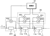
- FIG. 4 is a block diagram illustrating an example of a functional configuration of the current measurement unit 24 and the voltage measurement unit 25 according to the first embodiment.
- the current measurement unit 24 includes a shunt resistor 241 connected in series to the plurality of power storage cells 11 connected in series, and a voltmeter 242 that measures a voltage across the shunt resistor 241.
- the voltmeter 242 is connected to the calculation unit 21.
- the voltmeter 242 measures the voltage V S across the shunt resistor 241, and inputs the measured value of the voltage V S to the calculation unit 21.
- the value of the resistance R s of the shunt resistor 241 is stored in advance in the storage unit 23.
- the BMU 2 measures the current I flowing through the plurality of power storage cells 11 using the current measuring unit 24.
- one shunt resistor 241 is connected to each set of storage cells 11 in series.
- Voltage measuring unit 25 includes voltmeters 251 connected to both ends of each storage cell 11. Each of the voltmeters 251 is connected to the calculation unit 21. The voltmeter 251 measures the voltage at both ends of the storage cell 11 and inputs the measured voltage value to the calculation unit 21. In this manner, the BMU 2 uses the voltage measurement unit 25 to measure the voltage of each storage cell 11.
- FIG. 4 shows an equivalent circuit of the storage cell 11.
- the storage cell 11 is represented by an equivalent circuit in which an electromotive force 114 and an internal resistance 115 are connected in series.
- the value of the internal resistance 115 is R 0
- the value of the electromotive force 114 is E 0
- the voltage measured by the voltmeter 251 is V
- the current flowing through the storage cell 11 is I.
- the value R 0 of the internal resistance 115 obtained is the DC resistance of the storage cell 11.
- FIG. 5 is a schematic diagram illustrating an example of storage contents of the storage unit 23 according to the first embodiment.
- the storage unit 23 stores an OS program 231 that is a real-time OS (Operating @ System) program and a calculation program 232 that is a program for performing various calculations.
- the arithmetic unit 21 realizes a real-time OS by executing processing according to the OS program 231.
- the calculation program 232 operates on a real-time OS.
- the calculation unit 21 calculates the SOC of the power storage cell 11 by the current integration method, calculates the internal resistance of the power storage cell 11, calculates the amount of heat generated in the power storage cell 11, and calculates the power of the power storage cell 11 according to the calculation program 232. Perform calculations to estimate temperature.
- the storage unit 23 stores characteristic data 233 including information indicating various characteristics of the power storage module 10 necessary for performing various calculations.
- the characteristic data 233 includes the resistance R s of the shunt resistor 241 and includes the thermal conductivity, specific heat, density, and heat transfer coefficient of each part of the power storage module 10 to the outside.
- the characteristic data 233 includes an SOC-OCV curve representing a correlation between the SOC of the storage cell 11 and an OCV (Open Circuit Voltage).
- Information included in the characteristic data 233 is specified in advance and stored in the storage unit 23.
- the storage unit 23 stores history data 234 including a history of measured values and calculated values.
- the history data 234 includes, for example, a history of measured current and voltage, and a history of calculated SOC. The values included in the history data 234 are obtained by the processing of the BMU 2 and are sequentially stored in the storage unit 23.
- the BMU 2 calculates the SOC of each storage cell 11 by the current integration method. More specifically, the calculation unit 21 calculates the current flowing in each of the storage cells 11 based on the measurement result of the current measurement unit 24, and sequentially calculates the SOC according to the calculation program 232 to calculate the SOC. I do. The calculation unit 21 repeats the calculation of the SOC, and stores the calculated SOC in the storage unit 23.
- the BMU 2 performs a process of estimating the temperature of each power storage cell 11 as needed.
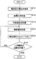
- FIG. 6 is a flowchart illustrating a procedure of a process for estimating the temperature of the power storage cell 11 performed by the BMU 2 according to the first embodiment.
- the calculation unit 21 performs the following processing according to the calculation program 232. Hereinafter, the step is abbreviated as S.
- S the step is abbreviated as S.
- the calculation unit 21 calculates the value of the electromotive force 114 of each power storage cell 11 (S12).
- the SOC-OCV curve indicates a one-to-one correspondence between the SOC and the OCV.
- the OCV of the storage cell 11 is obtained according to the SOC-OCV curve.
- the OCV of the storage cell 11 is substantially equal to the value of the electromotive force 114 of the storage cell 11.
- the SOC-OCV curve specified in advance for each power storage cell 11 may be stored in the storage unit 23, or an average SOC-OCV curve may be stored in the storage unit 23.
- the operation unit 21 reads out the latest SOC and SOC-OCV curve of each power storage cell 11 from the storage unit 23, and specifies the OCV corresponding to the SOC according to the SOC-OCV curve.
- the calculation unit 21 sets the specified OCV to the value E 0 of the electromotive force 114 for each of the power storage cells 11.
- the calculation unit 21 calculates the value of the internal resistance 115 of each power storage cell 11 (S13).
- the calculation unit 21 thereafter calculates the future heat generation amount in the power storage cell 11 using the value R 0 of the internal resistance 115, and simulates the heat conduction in the power storage module 10 so that the future power storage A process for estimating the temperature of the cell 11 is performed.
- the value R 0 of the internal resistance 115 calculated in S13 is the value of the internal resistance 115 at time t 0 .
- Arithmetic unit 21 performs a process of estimating the temperature of power storage cell 11 at time t 1 after time t 0 .
- the value of the time t 1 is predetermined and stored in the storage unit 23. The value of time t 1 may be changeable.
- the calculation unit 21 calculates the amount of heat generated in each power storage cell 11 (S14).
- the storage cell 11 generates heat due to the activation overvoltage and the ohmic overvoltage.
- the heat generated by the activation overvoltage is Q react (unit is W)
- the current flowing through the storage cell 11 is I (unit is A)
- the activation overvoltage (unit is V) is ⁇
- the reaction resistance is R react (unit is ohm). I do.
- the activation overvoltage IR react .
- the heat generated by the ohmic overvoltage is Q ohm (unit is W), the ohmic overvoltage (unit is V) is V ohm , and the ohmic resistance is R ohm (unit is ohm).
- the total heat generation Q total (unit: W) in the storage cell 11 is expressed by the following equation.
- the arithmetic unit 21 uses the current I measured at S11.
- the calculation unit 21 estimates a future current I according to the energization profile, and calculates the heat value Q using the estimated current I.
- the predicted (assumed) specific energization profile is used as the predicted energization profile.
- the calculation unit 21 may continue to use the current I measured in S11.
- the calculation unit 21 may calculate an average current in the past for a predetermined time based on the history of the current stored in the storage unit 23, and use the calculated average current as the current I.
- the calculation unit 21 may specify the maximum current within a predetermined time in the past, assume an energization profile in which the maximum current flows, and use the maximum current as the current I.
- the calculation unit 21 may predict the energization profile by statistical calculation or machine learning based on the history of the current, and use the current I according to the predicted energization profile.
- the calculation unit 21 performs a simulation of heat conduction (S15).
- the calculation unit 21 performs a calculation to solve the heat conduction equation by a numerical calculation using a predetermined method such as a finite element method, a finite volume method, or a finite difference method, so that the power storage module after a predetermined time ⁇ t Calculate the temperature at each part of 10.
- the heat conduction equation is represented by the following equation (1).
- ⁇ density (unit is kg / m 3 )
- C p constant pressure specific heat (unit is J / kg / K)
- T temperature (unit is K)
- t time (unit is s).
- K is the thermal conductivity (unit is W / m / K)
- ⁇ is the nabula.
- the calculation unit 21 uses values previously stored in the storage unit 23 as the thermal conductivity k, the constant-pressure specific heat C p , the density ⁇ , and the heat transfer coefficient to the outside of each part of the power storage module 10.
- the calculation unit 21 may use a different value depending on the direction of heat conduction as the heat conductivity k.
- the calculation unit 21 uses the external temperature measured by the temperature measurement unit 26 as the outside air temperature required for the simulation.
- the calculation unit 21 uses the total heat value Q total calculated in S14 as Q total in the equation (1).
- Arithmetic unit 21 uses the temperature inside power storage module 10 measured by temperature measurement unit 26 as the temperature at each part of power storage module 10 at time t 0 .
- the calculation unit 21 may perform a process of generating a model of the power storage module 10 necessary for numerical calculation, or may read out and use the model of the power storage module 10 stored in the storage unit 23 in advance. The same method can be applied when the outside of the power storage module 10 is liquid-cooled by water cooling or the like. Further, an entropy heat generation term (a reversible reaction heat in which heat generation and heat absorption are reversed depending on the direction of charge and discharge) may be further added to Q total .
- Calculating unit 21 determines whether to calculate the temperature of t 1 hour after each of the storage cells 11 from the time t 0 by the processing of S15 (S16). If the time t 0 has not been calculated yet the temperature of 1 hour after t (S16: NO), the arithmetic unit 21 returns the process to S14. By the processes of S14 and S15 to be executed next, the arithmetic unit 21 calculates the temperatures in the respective parts of the power storage module 10 after a time ⁇ t. Calculation unit 21, from the time t 0 to a temperature of 1 hour after t is obtained, repeats the processing of S14 ⁇ S16.
- the calculation unit 21 ends the process of estimating the temperature of the power storage cell 11.
- S11 by executing the processing in ⁇ S16
- BMU 2 estimates the temperature of t 1 hour after each of the storage cells 11 from the time t 0.
- the calculation unit 21 may calculate a plurality of kinds of heat values based on a plurality of energization profiles in S14, and may perform a process of calculating a plurality of temperatures based on the plurality of heat amounts in S15. . In this case, a plurality of estimated temperatures according to a plurality of energization profiles are obtained. The estimation of the temperature of the storage cell 11 can be calculated at the same time without reducing the energization profile to one.
- the BMU 2 can appropriately adjust the temperature of the power storage cell 11 by comparing a plurality of types of estimated temperatures, selecting an energization profile that provides an appropriate temperature, and controlling the current according to the selected energization profile. The BMU 2 can also compare a plurality of estimated temperatures with the actual temperature measured by the temperature measurement unit 26 and select an energization profile whose estimated temperature is close to the actual temperature.
- the BMU 2 executes the processing of S11 to S16 as needed, and controls the operation of the power storage module 10 based on the estimated temperature. For example, BMU 2 adjusts the temperature of power storage cell 11 by adjusting the current flowing through power storage cell 11 based on the estimated temperature. For example, the BMU 2 adjusts the current flowing through the storage cell 11 so that the temperature of the storage cell 11 does not exceed a predetermined upper limit temperature. It is also possible to simulate the deterioration of the storage cell 11 according to the temperature of the storage cell 11 estimated by the BMU 2.
- the BMU 2 calculates the value of the internal resistance 115 of the power storage cell 11 by the DC resistance measurement method, and calculates the amount of heat generated in the power storage cell 11 based on the value of the internal resistance 115.
- the temperature of the power storage cell 11 in the future is estimated based on the estimated heat value.
- the obtained value of the internal resistance 115 is the value of the DC resistance.
- the heat generation factor of the storage cell 11 is substantially limited to DC resistance. For this reason, the calorific value in the storage cell 11 can be accurately estimated using the value of the internal resistance 115 of the storage cell 11 calculated by the DC resistance measurement method.
- This estimation can be realized by hardware normally included in a typical power storage module 10 (no additional hardware is required for the power storage module 10).
- the BMU 2 can more accurately calculate the value of the internal resistance 115 of the storage cell 11 charged and discharged with DC by using the DC resistance measurement method instead of the AC impedance method.
- the BMU 2 estimates the calorific value of the power storage cell 11 without using an internal resistance map that causes an error, and thus can estimate the calorific value with a small error. Since the BMU 2 estimates the value of the internal resistance 115 in situ based on the SOC, current, and voltage when the power storage cell 11 is actually charged / discharged, the value of the internal resistance 115 of the power storage cell 11 that is actually in use is easily determined. Can be estimated. Further, since the AC impedance method is not used, one measuring device is not required for each storage cell 11.
- the BMU 2 can easily and accurately calculate the value of the internal resistance 115 of the storage cell 11 in use, and easily and accurately calculate the amount of heat generated in the storage cell 11 and the temperature of the storage cell 11 in the future. Can be estimated well.
- the calculation formula required for estimating the temperature of the storage cell 11 is a simple formula. Therefore, the BMU 2 can execute the calculation for estimating the temperature of the power storage cell 11 at a high speed.
- the BMU 2 can execute processing with high responsiveness, such as making the calculation processing time required for the processing for estimating the temperature of the power storage cell 11 after t 1 time less than t 1 . Therefore, the BMU 2 can estimate the future temperature of the power storage cell 11 at high speed in advance. If the responsiveness is sufficient, the BMU 2 does not need to use the real-time OS.
- the BMU 2 can accurately estimate the temperature of the power storage cell 11, the operation of the power storage module 10 can be appropriately controlled according to the estimated temperature. Further, the BMU 2 can accurately predict the deterioration of the power storage cell 11 according to the temperature. For example, it is possible to accurately predict when to replace the storage cell 11 that has deteriorated to some extent.
- FIG. 7 is a block diagram illustrating an example of a functional configuration of the current measurement unit 24 and the voltage measurement unit 25 according to the second embodiment.
- the configuration of the current measuring unit 24 is the same as that of the first embodiment.
- Voltage measurement unit 25 includes current sources 252 connected to both ends of each storage cell 11.
- Current source 252 is connected to power storage cell 11 in parallel with voltmeter 251.
- the current source 252 can generate a direct current, and can change the direction in which the direct current flows.
- the configuration of the BMU 2 other than the voltage measurement unit 25 is the same as that of the first embodiment.
- the configuration of the portion other than the BMU 2 of the power storage module 10 is the same as that of the first embodiment.
- the current flowing from the current source 252 to the storage cell 11 in the same direction as the current I flowing through the storage cell 11 is defined as a first DC current.
- the current flowing from the current source 252 to the storage cell 11 in a direction opposite to the current I flowing through the storage cell 11 is defined as a second DC current.
- the second DC current is in a direction opposite to the first DC current.
- the absolute value of the first DC current and the absolute value of the second DC current are the same value, and this value is defined as i.
- the value of the internal resistor 115 is R 0
- the value of the electromotive force 114 is E 0 .
- the BMU 2 repeatedly calculates the SOC of each power storage cell 11 by the current integration method, and stores the calculated SOC in the storage unit 23. Further, similarly to the first embodiment, the BMU 2 performs a process of estimating the temperature of each power storage cell 11 as needed.
- FIG. 8 is a flowchart illustrating a procedure of a process for estimating the temperature of the power storage cell 11 performed by the BMU 2 according to the second embodiment.
- the BMU 2 measures the voltage of each of the storage cells 11 in a state where a DC current flows through each of the storage cells 11 (S21).
- the current source 252 flows the first direct current to the storage cell 11, the voltmeter 251 measures a first voltage V 1. Further, in a state in which a DC current flows through the storage cell 11, the current source 252 flows the second DC current to the power storage cell 11, the voltmeter 251 measures a second voltage V 2. The voltmeter 251 inputs the measured first voltage V 1 and second voltage V 2 to the calculation unit 21.
- the calculation unit 21 calculates the value of the internal resistance 115 of each power storage cell 11 (S22).
- the absolute values i of the first DC current and the second DC current are stored in the storage unit 23 in advance.
- the calculation unit 21 reads out the absolute values i of the first DC current and the second DC current from the storage unit 23, and executes the process of S22.
- the absolute value i 1 of the first DC current may be different from the absolute value i 2 of the second DC current.
- R 0 (V 1 ⁇ V 2 ) / (i 1 + i 2 ).
- the calculation unit 21 thereafter calculates the future heat generation amount in the power storage cell 11 using the value R 0 of the internal resistance 115, and simulates the heat conduction in the power storage module 10 so that the future power storage A process for estimating the temperature of the cell 11 is performed.
- the calculation unit 21 calculates the heat value Q in each of the power storage cells 11 based on the predicted energization profile, similarly to the processing of S14 (S23).
- the calculation unit 21 performs a heat conduction simulation as in the process of S15 (S24).
- Computing section 21 determines whether to calculate the temperature of t 1 hour after each of the storage cells 11 from the time t 0 by the processing of S24 (S25).
- operation unit 21 returns the process to S23.
- the calculation unit 21 ends the process of estimating the temperature of the power storage cell 11.
- BMU 2 estimates the temperature of t 1 hour after each of the storage cells 11 from the time t 0.
- the BMU 2 executes the processes of S21 to S25 as needed, and controls the operation of the power storage module 10 based on the estimated temperature.
- the BMU 2 calculates the value of the internal resistance 115 of the storage cell 11 based on the first voltage V 1 and the second voltage V 2 by using the current source 252.
- the value of the internal resistance 115 can be obtained without using the value E 0 of the electromotive force 114 of the storage cell 11 and the value of the current flowing through the storage cell 11. For this reason, the BMU 2 can calculate the value of the internal resistance 115 of the storage cell 11 more accurately, and can more accurately estimate the calorific value of the storage cell 11 and the temperature of the storage cell 11 in the future.
- the BMU 2 can easily and accurately calculate the value of the internal resistance 115 of the storage cell 11 charged and discharged by DC by using the DC resistance measurement method. For this reason, the BMU 2 can easily and accurately estimate the amount of heat generated in the power storage cell 11 and further easily and accurately estimate the temperature of the power storage cell 11 in the future.
- FIG. 9 is a block diagram illustrating an example of a functional configuration of the power storage module 10 and the battery management device 3 according to the third embodiment.
- the CMU (Cell Monitoring Unit) 20 includes a communication unit 27.
- the communication unit 27 has a function of transmitting and receiving information to and from the outside of the power storage module 10.
- the configuration of the parts other than the communication unit 27 of the CMU 20 is the same as that of the BMU 2 in the first or second embodiment.
- the configuration of the portion other than the CMU 20 of the power storage module 10 may be similar to that of the first or second embodiment.
- the communication unit 27 is connected to the battery management device 3 outside the power storage module 10.
- the battery management device 3 includes a control unit 31, a communication unit 32, and a storage unit 33.
- the battery management device 3 is configured by a computer.
- Battery management device 3 may be composed of a plurality of computers.
- Battery management device 3 may be connected to CMU 20 via a communication network such as the Internet.
- the control unit 31 is configured using, for example, a CPU and memories such as a ROM (Read Only Memory) and a RAM (Random Access Memory).
- the control unit 31 controls the entire battery management device 3.
- the control unit 31 may be configured using a CPU and a GPU (Graphics Processing Unit), a multi-core CPU, or a TPU (Tensor Processing Unit).
- the storage unit 33 is non-volatile, and is configured using, for example, a hard disk or a non-volatile memory.
- the storage unit 33 stores a computer program 331.
- the computer program 331 includes, for example, programs corresponding to the OS program 231 and the calculation program 232.
- the control unit 31 executes information processing based on the computer program 331.
- the CMU 20 transmits information indicating the current measured using the current measuring unit 24 and information indicating the voltage measured using the voltage measuring unit 25 from the communication unit 27 to the battery management device 3.
- the battery management device 3 receives the information transmitted from the CMU 20 by the communication unit 32, and stores the received information in the storage unit 33.
- the characteristic data 233 may be stored in the storage unit 33 in advance, or may be read from the storage unit 23 as necessary and transmitted from the communication unit 27 to the battery management device 3.
- the history data 234 may be stored in the storage unit 33, and the information included in the history data 234 may be read from the storage unit 23 as needed, and transmitted from the communication unit 27 to the battery management device 3.
- the CMU 20 measures the current flowing in each of the storage cells 11 and transmits information indicating the measured current from the communication unit 27 to the battery management device 3.
- the battery management device 3 receives the information indicating the current through the communication unit 32, and the control unit 31 calculates the SOC of each power storage cell 11 by the current integration method based on the current indicated by the received information.
- the control unit 31 repeatedly calculates the SOC of each power storage cell 11 and stores the calculated SOC in the storage unit 33.
- the operation unit 21 may calculate the SOC.
- the CMU 20 and the battery management device 3 perform a process of estimating the temperature of each power storage cell 11.
- the CMU 20 executes the same processing as the processing of S11 in the first embodiment, and transmits information indicating the current flowing in the power storage cell 11 and the voltage of the power storage cell 11 from the communication unit 27 to the battery management device 3.
- CMU20 performs the same processing as step S21 in the second embodiment, the measured first information indicating the voltages V 1 and the second voltage V 2 has, from the communication unit 27 to the battery management unit 3.
- the battery management device 3 receives the information transmitted from the CMU 20 by the communication unit 32.
- the control unit 31 estimates the temperature of each power storage cell 11 after a time t 1 from time t 0 by executing the same processing as the processing from S12 to S16 in the first embodiment.
- the control unit 31 estimates the temperature of each of the power storage cells 11 after the time t 1 from the time t 0 by executing the same processing as the processing of S22 to S25 in the second embodiment.
- Arithmetic unit 21 may perform a process of generating a model of power storage module 10 necessary for numerical calculation.
- the model of the power storage module 10 may be stored in the storage unit 33 in advance, or may be transmitted from the CMU 20 to the battery management device 3 as needed.
- the battery management device 3 transmits information indicating the estimated temperature of each power storage cell 11 from the communication unit 32 to the CMU 20.
- the CMU 20 receives information indicating the temperature of each power storage cell 11 by the communication unit 27.
- the CMU 20 and the battery management device 3 execute a process of estimating the temperature of each power storage cell 11 as needed.
- CMU 20 controls the operation of power storage module 10 based on the estimated temperature.
- the battery management device 3 can easily and accurately calculate the value of the internal resistance 115 of the storage cell 11 charged and discharged by DC by using the DC resistance measurement method. For this reason, the battery management device 3 can easily and accurately estimate the amount of heat generated in the power storage cell 11 and further easily and accurately estimate the temperature of the power storage cell 11 in the future.
- FIG. 9 shows an example in which the CMU 20 included in the single power storage module 10 is connected to the battery management device 3.
- a plurality of CMUs 20 included in a plurality of power storage modules 10 may be connected to the battery management device 3.
- the battery management device 3 transmits and receives information to and from each of the CMUs 20 and performs a process of estimating the temperature of the storage cells 11 for each of the storage modules 10.
- the storage cells 11 in the first to third embodiments may be reused (recycled).
- all the power storage cells 11 included in the power storage module 10 may be reusable products, and the reusable power storage cells 11 and new power storage cells 11 may be mixed in the power storage module 10.
- demand for secondary batteries such as lithium-ion batteries is expected to increase, it is predicted that output of specific elements such as cobalt used for the materials of secondary batteries will be insufficient. For this reason, it is expected that the storage cell will be reused.
- Reused storage cells are deteriorating and the internal resistance is increasing.
- the degree of progress of deterioration is affected by many factors such as the amount of electricity, the usage history, and the number of years elapsed. Since the internal resistance is increased, the temperature of the reusable storage cell is higher than that of a new storage cell, and the deterioration is more likely to progress.
- the value of the internal resistance 115 of the power storage cell 11 can be easily and accurately calculated by the same method.
- the temperature of the future storage cell 11 can be easily and accurately estimated.
- the operation of the storage battery module 10 can be appropriately controlled. For example, the operation of the power storage module 10 can be controlled while suppressing further deterioration of the power storage cell 11.
- the power storage module 10 may include a single power storage cell 11.
- the power storage device is the power storage module 10.
- the power storage device may be a bank configured by connecting a plurality of power storage modules 10 in series, or a domain configured by connecting a plurality of banks in parallel.
- the same processing as in the first to third embodiments is executed by the battery management device provided in the bank or the domain, or by the battery management device connected to the bank or the domain.
- the storage element is the storage cell 11.
- the storage element may be the storage module 10 or a bank.
- the simulation model used for the heat conduction simulation may be a model in which an electrode body and the like inside the electric storage element are divided into elements in detail.
- One power storage element can be used as one calculation element, or a large-scale power storage device can include a plurality of power storage elements as one calculation element.
- the present invention can be more effectively implemented by determining a model by comprehensively considering the performance of the calculation unit, the scale of the power storage device, the communication speed, and the like.
- the CMU 20 and the battery management device 3 in the third embodiment may be built in the same storage box (battery panel), or may be arranged close to each other for wireless communication connection. From the viewpoint of real-time responsiveness or communication load, it is preferable that the estimation is performed by the BMU 2 provided in the power storage module as in the first embodiment.
- Embodiments 1 to 3 When converting a new or reused power storage cell into a power supply system for industrial use, the technologies of Embodiments 1 to 3 may be applied. Many power storage modules are used in a power supply system for power adjustment and an AGV (Automated Guided Vehicle). The techniques of Embodiments 1 to 3 may be applied to improve the maintenance efficiency of these power storage modules and further stabilize system operation. When the reused storage cell is used, it is expected that the effects of applying the technologies of Embodiments 1 to 3 are particularly high.
- a future heat generation amount in the storage element is estimated using the predicted energization profile.
- the current heat generation amount in the power storage element may be estimated using a past energization profile (history data).
Landscapes
- Engineering & Computer Science (AREA)
- Manufacturing & Machinery (AREA)
- Chemical & Material Sciences (AREA)
- Chemical Kinetics & Catalysis (AREA)
- Electrochemistry (AREA)
- General Chemical & Material Sciences (AREA)
- Power Engineering (AREA)
- Physics & Mathematics (AREA)
- General Physics & Mathematics (AREA)
- Secondary Cells (AREA)
- Tests Of Electric Status Of Batteries (AREA)
- Charge And Discharge Circuits For Batteries Or The Like (AREA)
Abstract
蓄電装置(10)は、蓄電素子(11)と、前記蓄電素子の電圧を測定し、前記蓄電素子を管理する管理部(2)とを備える。管理部は、前記蓄電素子に直流電流が流れる状態で、前記蓄電素子の電圧を測定し、測定した電圧を用いた直流抵抗測定法により、前記蓄電素子の内部抵抗を計算し、前記内部抵抗及び通電プロファイルに基づいて、前記蓄電素子での発熱量を推定する。
Description
本発明は、蓄電素子の温度を推定する蓄電装置及び温度推定方法に関する。
蓄電素子(Energy Storage Device)は、無停電電源装置、安定化電源に含まれる直流又は交流電源装置等に広く使用されている。また、発電された電力を蓄電しておく大規模なシステムでの蓄電素子の利用が拡大している。典型的には、複数の蓄電素子を直列又は直並列に接続して蓄電システムが構成されている。
蓄電素子に大電流が流れた場合、又は高温環境下に蓄電素子がさらされた場合は、蓄電素子の温度が高くなる。高温状態では、蓄電素子の劣化が促進される。例えば、蓄電素子の満充電時の容量が減少する。蓄電素子を安定的に運用するために、電流、電圧又は温度等の蓄電素子の状態を監視することが行われている。
蓄電素子の電流及び電圧は、電流センサ及び電圧センサを用いて比較的容易に検出できる。しかし、蓄電素子の内部の温度又は発熱量を検出することは困難である。従来は、例えば、蓄電素子の近傍に配置したサーミスタ等の温度センサを用いて蓄電素子の外部温度を測定し、測定された温度が蓄電素子の制御に利用されている。
特許文献1には、蓄電素子の温度を推定する方法が開示されている。具体的には、交流インピーダンス法を用いて取得した蓄電素子の内部抵抗と、充放電が開始されてからの継続時間と、蓄電素子のSOC(State of Charge ;充電状態)と、蓄電素子の温度との関係を示す内部抵抗マップを用い、所定時間毎に内部での発熱量を算出している。推定した温度に基づき、冷却装置により蓄電素子が冷却される。
蓄電素子は、実際には直流で充放電されることが多い。特許文献1に記載の交流インピーダンス法では、反応抵抗又は拡散抵抗の値を正確に把握し難く、直流で充放電されるときの蓄電素子の内部抵抗を取得することは困難であると予想される。予め実験により作成した内部抵抗マップを用いる場合、実験時の条件(例えば、充放電が開始されてからの継続時間)と実使用時の条件とがずれることによって、発熱量の推定誤差が拡大する。また、蓄電素子の内部抵抗と、充放電が開始されてからの継続時間と、SOCと、蓄電素子の温度との関係性は、蓄電素子の劣化に伴って変化する。蓄電素子の劣化を考慮した精緻な内部抵抗マップを作成することは、困難である。従って、実際に使用中の蓄電素子の温度を特許文献1に記載の方法で推定することは、困難である。
更に、交流インピーダンス法では、蓄電素子一つにつき測定装置が一台必要とされる。特許文献1に記載の技術を、複数の蓄電素子を備えた蓄電装置又は蓄電システムに適用して、個々の蓄電素子の温度を推定することは、困難である。
本発明は、蓄電素子の温度を容易に推定できる蓄電装置及び温度推定方法を提供することを目的とする。
本発明の一局面に係る蓄電装置は、蓄電素子と、前記蓄電素子の電圧を測定し、前記蓄電素子を管理する管理部とを備え、該管理部は、前記蓄電素子に直流電流が流れる状態で、前記蓄電素子の電圧を測定し、測定した電圧を用いた直流抵抗測定法により、前記蓄電素子の内部抵抗を計算し、前記内部抵抗及び通電プロファイルに基づいて、前記蓄電素子での発熱量を推定する。
本発明の一局面に係る温度推定方法は、蓄電素子の温度を推定する方法であって、前記蓄電素子に直流電流が流れる状態で、前記蓄電素子の電圧を測定し、測定した電圧を用いた直流抵抗測定法により、前記蓄電素子の内部抵抗を計算し、前記内部抵抗及び通電プロファイルに基づいて、前記蓄電素子での発熱量を推定し、前記発熱量に基づいて、熱伝導のシミュレーションを行うことにより、前記蓄電素子の温度を推定する。
上記構成により、直流で充放電される蓄電素子の内部抵抗を容易に計算でき、蓄電素子での発熱量を容易に推定することができる。予測通電プロファイルを用いることにより、将来(例えば、数秒後、又は数分後)の蓄電素子の温度を推定することもできる。
蓄電装置は、蓄電素子と、前記蓄電素子の電圧を測定し、前記蓄電素子を管理する管理部とを備え、該管理部は、前記蓄電素子に直流電流が流れる状態で、前記蓄電素子の電圧を測定し、測定した電圧を用いた直流抵抗測定法により、前記蓄電素子の内部抵抗を計算し、前記内部抵抗及び通電プロファイルに基づいて、前記蓄電素子での発熱量を推定する。
蓄電装置は、蓄電素子と管理部とを備える。管理部は、蓄電素子に直流電流が流れる状態で蓄電素子の電圧を測定し、直流抵抗測定法により蓄電素子の内部抵抗を計算する。管理部は、交流インピーダンス法ではなく直流抵抗測定法を用いることで、直流で充放電されることが多い蓄電素子の内部抵抗を容易に精度良く計算できる。また、管理部は、内部抵抗及び通電プロファイルに基づいて、蓄電素子での発熱量を推定する。直流抵抗測定法で得られる内部抵抗は、直流抵抗である。多くの場合、蓄電素子は直流で充放電されるので、蓄電素子の発熱因子はほぼ直流抵抗に限定される。このため、直流抵抗測定法により計算した蓄電素子の内部抵抗を用いて、蓄電素子での発熱量を精度良く推定できる。
蓄電装置は、前記通電プロファイルとして、予測通電プロファイルを用い、前記蓄電素子での将来の発熱量を推定してもよい。
従来、蓄電素子の近未来の発熱量をin situ推定(その場推定)することについて、十分な検討がなされてこなかった。特に、温度センサにより測定される蓄電素子の外部温度に依拠せずに、蓄電素子の内部抵抗に基づく発熱量を逐次推定することについて、改善の余地があった。蓄電装置に備えられた管理部において、直流抵抗測定法により計算される内部抵抗を用いて近未来の発熱量を推定することで、蓄電素子の劣化を抑制すること、又は蓄電素子の性能を存分に使いきることが可能となる。
従来、蓄電素子の近未来の発熱量をin situ推定(その場推定)することについて、十分な検討がなされてこなかった。特に、温度センサにより測定される蓄電素子の外部温度に依拠せずに、蓄電素子の内部抵抗に基づく発熱量を逐次推定することについて、改善の余地があった。蓄電装置に備えられた管理部において、直流抵抗測定法により計算される内部抵抗を用いて近未来の発熱量を推定することで、蓄電素子の劣化を抑制すること、又は蓄電素子の性能を存分に使いきることが可能となる。
前記管理部は、前記蓄電素子に直流電流が流れる状態で、前記蓄電素子に流れる電流を測定し、前記蓄電素子のSOCに応じて得られる前記蓄電素子の起電力と、測定した電流と、前記測定した電圧とに基づいて、前記蓄電素子の内部抵抗を計算してもよい。蓄電素子に直流電流が流れる状態で測定された電流及び電圧、並びに蓄電素子の起電力を用いて、簡便な計算により、蓄電素子の内部抵抗が得られる。
一つの電流測定部に直列接続された複数の蓄電素子(蓄電セル)のそれぞれについて、SOCに応じた起電力と、測定した電流と、測定した蓄電素子の電圧とに基づいて、内部抵抗を計算することが好ましい。このような計算は、典型的な蓄電装置(蓄電モジュール)が通常備えるハードウェアで実現できる(蓄電装置には、追加ハードウェアが不要である)。
前記管理部は、前記蓄電素子に並列接続された電流源を有し、前記蓄電素子に直流電流が流れる状態で前記電流源が第1の直流電流を前記蓄電素子に印加した場合に、前記蓄電素子の第1電圧を測定し、前記蓄電素子に直流電流が流れる状態で、前記第1の直流電流とは異なる値の第2の直流電流を前記電流源が前記蓄電素子に印加した場合に、前記蓄電素子の第2電圧を測定し、前記第1電圧及び前記第2電圧に基づいて、前記蓄電素子の内部抵抗を計算してもよい。電流源を利用することにより、蓄電素子の起電力及び蓄電素子に流れる電流を用いることなく、第1電圧及び第2電圧に基づいて蓄電素子の内部抵抗が得られる。
前記管理部は、前記発熱量に基づいて、熱伝導のシミュレーションを行うことにより、前記蓄電素子の温度を推定してもよい。精度良く推定された蓄電素子での発熱量を用いて、蓄電素子の温度が容易に精度良く推定できる。
前記管理部は、プログラムを記憶する記憶部と、前記プログラムに基づいた演算を行う演算部とを有し、前記記憶部は、リアルタイムOS(Operating System)のプログラムと、前記リアルタイムOS上で動作し、前記内部抵抗の計算、前記発熱量の推定及び前記温度の推定を行うためのプログラムを記憶してもよい。リアルタイムOSを利用することにより、管理部は、高い応答性で処理を実行できる。従って、管理部は、高速で将来の蓄電素子の温度を推定できる。応答性が十分である場合は、管理部はリアルタイムOSを用いなくてもよい。
前記管理部は、前記予測通電プロファイルに応じた将来の電流及び前記内部抵抗を用いて発熱量を計算することにより、前記蓄電素子での将来の発熱量を推定してもよい。直流抵抗測定法により計算した蓄電素子の内部抵抗と、通電プロファイルに応じた将来の電流とを用いて、蓄電素子での将来の発熱量を精度良く推定できる。
前記管理部は、複数の予測通電プロファイルに基づいて、複数通りの発熱量を推定してもよい。管理部は、複数通りの発熱量に応じて、複数通りの温度を推定できる。通電プロファイルを一つに絞らずとも、蓄電素子の温度の推定が可能である。
前記蓄電素子はリユース品(リサイクル品)であってもよい。蓄電素子がリユース品であっても、同様の方法にて蓄電素子の内部抵抗を容易に精度良く計算でき、蓄電素子の温度を容易に精度良く推定できる。リユース品の蓄電素子の内部抵抗及び温度を正しく把握して、適切に蓄電素子を制御できる。
温度推定方法は、蓄電素子の温度を推定する方法であって、前記蓄電素子に直流電流が流れる状態で、前記蓄電素子の電圧を測定し、測定した電圧を用いた直流抵抗測定法により、前記蓄電素子の内部抵抗を計算し、前記内部抵抗及び通電プロファイルに基づいて、前記蓄電素子での発熱量を推定し、前記発熱量に基づいて、熱伝導のシミュレーションを行うことにより、前記蓄電素子の温度を推定する。直流抵抗測定法を用いることで、直流で充放電される蓄電素子の内部抵抗を容易に精度良く計算できる。このため、蓄電素子での発熱量を容易に精度良く推定し、蓄電素子の温度を容易に精度良く推定できる。
以下、本発明をその実施の形態を示す図面に基づき具体的に説明する。
(実施形態1)
図1は、蓄電セル11の外観の例を示す模式図である。蓄電セル11は蓄電素子に対応する。蓄電セル11は、リチウムイオン電池等の二次電池である。蓄電セル11は、直方体の形状(prismatic shape )を有している。蓄電セル11は、直方体形状のケース111と、正端子112と、負端子113とを備えている。ケース111の内部には、正極、負極、セパレータ及び電解質(電解液)が収容されている。セパレータは正極及び負極の間に介在されている。例えば、正極、負極及びセパレータはシート状であり、それらを重ねて巻回した電極体としてケース111内に収容されている。電極体は、巻回型のものに限らず、積層型のものであってもよい。正極は正端子112に接続され、負極は負端子113に接続されている。蓄電セル11の長さが最も短い方向を厚み方向とする。なお、蓄電セル11の形状は直方体以外の形状であってもよく、パウチ形又は円筒形であってもよい。
(実施形態1)
図1は、蓄電セル11の外観の例を示す模式図である。蓄電セル11は蓄電素子に対応する。蓄電セル11は、リチウムイオン電池等の二次電池である。蓄電セル11は、直方体の形状(prismatic shape )を有している。蓄電セル11は、直方体形状のケース111と、正端子112と、負端子113とを備えている。ケース111の内部には、正極、負極、セパレータ及び電解質(電解液)が収容されている。セパレータは正極及び負極の間に介在されている。例えば、正極、負極及びセパレータはシート状であり、それらを重ねて巻回した電極体としてケース111内に収容されている。電極体は、巻回型のものに限らず、積層型のものであってもよい。正極は正端子112に接続され、負極は負端子113に接続されている。蓄電セル11の長さが最も短い方向を厚み方向とする。なお、蓄電セル11の形状は直方体以外の形状であってもよく、パウチ形又は円筒形であってもよい。
図2は、蓄電モジュール10の外観の例を示す模式図である。蓄電モジュール10は蓄電装置に対応する。蓄電モジュール10は、直列及び/又は並列に接続された複数の蓄電セル11を含んでいる。蓄電モジュール10は、保持部材の一例である直方体状の筐体12を備えている。複数の蓄電セル11は、厚み方向に並べられ、筐体12に保持(収納)されている。代替的に、保持部材は、一対のエンドプレートとそれらエンドプレートを繋ぐ複数の締結バーとによって形成されてもよい。複数の蓄電セル11は、図示しないバスバーによって直列及び/又は並列に接続される。
更に、蓄電モジュール10は、BMU(Battery Management Unit;電池管理装置)2を備えている。BMU2は、管理部に対応する。図2では、BMU2を破線で示している。BMU2は、基板上に各種の部品が配置された構成となっている。BMU2は、蓄電モジュール10に含まれる蓄電セル11を管理する。具体的には、BMU2は、電流積算法により、蓄電セル11のSOCを計算する。SOCは、蓄電セル11の満充電容量に対して、蓄電セル11に充電されている電気量を比率で表したものである。また、BMU2は、蓄電セル11の温度を推定する処理を行う。
図3は、実施形態1に係る蓄電モジュール10の機能構成の例を示すブロック図である。蓄電モジュール10では、例えば、複数の蓄電セル11が直列に接続されている。BMU2は、演算部21と、メモリ22と、記憶部23と、電流測定部24と、電圧測定部25と、温度測定部26とを備えている。演算部21は、例えば、CPU(Central Processing Unit)である。メモリ22は、演算部21での演算に必要な情報を記憶する。記憶部23は、不揮発性であり、プログラム及びデータを記憶する。演算部21は、記憶部23が記憶するプログラムに従って処理を実行する。例えば、記憶部23は不揮発性の半導体メモリである。温度測定部26は、温度センサを用いて、蓄電モジュール10の外部の温度を測定する。
図4は、実施形態1に係る電流測定部24及び電圧測定部25の機能構成の例を示すブロック図である。電流測定部24は、直列に接続された複数の蓄電セル11に直列に接続されたシャント抵抗241と、シャント抵抗241の両端の電圧を測定する電圧計242とを含んでいる。電圧計242は、演算部21に接続されている。
直列に接続された複数の蓄電セル11に直流電流が流れる場合、シャント抵抗241には複数の蓄電セル11と同一の電流Iが流れる。電圧計242は、シャント抵抗241の両端の電圧VS を測定し、測定した電圧VS の値を演算部21へ入力する。シャント抵抗241の抵抗Rs の値は予め記憶部23に記憶されている。演算部21は、シャント抵抗241の抵抗Rs を記憶部23から読み出し、シャント抵抗241の両端の電圧VS を用いて、I=VS /Rs の計算を行うことにより、電流Iを計算する。このようにして、BMU2は、直列に接続された複数の蓄電セル11に直流電流が流れる場合に、電流測定部24を用いて、複数の蓄電セル11に流れる電流Iを測定する。蓄電モジュール10内で複数組の蓄電セル11が互いに並列に接続されている場合は、各組の蓄電セル11に直列にシャント抵抗241が一つ接続されている。
電圧測定部25は、夫々の蓄電セル11の両端に接続された電圧計251を含んでいる。夫々の電圧計251は演算部21に接続されている。電圧計251は、蓄電セル11の両端の電圧を測定し、測定した電圧の値を演算部21へ入力する。このようにして、BMU2は、電圧測定部25を用いて、夫々の蓄電セル11の電圧を測定する。
図4には、蓄電セル11の等価回路を示している。蓄電セル11は、起電力114と内部抵抗115とが直列に接続された等価回路で表される。内部抵抗115の値をR0 、起電力114の値をE0 、電圧計251で測定した電圧をV、蓄電セル11に流れる電流をIとする。内部抵抗115の値R0 は、R0 =(V-E0 )/Iの計算により求められる。求められる内部抵抗115の値R0 は、蓄電セル11の直流抵抗である。
図5は、実施形態1に係る記憶部23の記憶内容の例を示す模式図である。記憶部23は、リアルタイムOS(Operating System)のプログラムであるOSプログラム231と、各種の計算を行うためのプログラムである計算プログラム232を記憶している。演算部21は、OSプログラム231に従った処理を実行することにより、リアルタイムOSを実現する。計算プログラム232は、リアルタイムOS上で動作する。演算部21は、計算プログラム232に従って、電流積算法による蓄電セル11のSOCの計算、蓄電セル11の内部抵抗の計算、蓄電セル11での発熱量の推定のための計算、及び蓄電セル11の温度を推定するための計算を行う。
記憶部23は、各種の計算を行うために必要な、蓄電モジュール10に関する各種の特性を示す情報を含んだ特性データ233を記憶する。例えば、特性データ233は、シャント抵抗241の抵抗Rs を含み、蓄電モジュール10の各部分の熱伝導率、比熱、密度、及び外部への熱伝達係数を含む。また、特性データ233は、蓄電セル11のSOCとOCV(Open Circuit Voltage;開回路電圧)との相関関係を表すSOC-OCV曲線を含んでいる。特性データ233に含まれる情報は、予め特定され、記憶部23に記憶されている。記憶部23は、測定した値及び計算した値の履歴を含んだ履歴データ234を記憶する。履歴データ234は、例えば、測定した電流及び電圧の履歴、並びに計算したSOCの履歴を含んでいる。履歴データ234に含まれる値は、BMU2の処理により得られ、順次記憶部23に記憶される。
次に、BMU2が実行する処理を説明する。BMU2は、電流積算法により夫々の蓄電セル11のSOCを計算する。より詳しくは、演算部21は、電流測定部24の測定結果に基づいて、夫々の蓄電セル11に流れる電流を計算し、計算プログラム232に従って、計算した電流を逐次積算することにより、SOCを計算する。演算部21は、SOCの計算を繰り返し、計算したSOCを記憶部23に記憶させる。
BMU2は、随時、夫々の蓄電セル11の温度を推定する処理を行う。図6は、実施形態1に係るBMU2が実行する蓄電セル11の温度を推定するための処理の手順を示すフローチャートである。演算部21は、計算プログラム232に従って以下の処理を実行する。以下、ステップをSと略す。蓄電モジュール10が充放電を行う際には、蓄電セル11には直流電流が流れる。演算部21は、夫々の蓄電セル11に直流電流が流れる状態で、蓄電セル11に流れる電流、及び蓄電セル11の電圧を測定する(S11)。S11では、前述したように、演算部21は、蓄電モジュール10の充放電により蓄電セル11に直流電流が流れる場合に、電流測定部24での測定結果を用いて、蓄電セル11に流れる電流Iを計算する。また、演算部21は、蓄電セル11に直流電流が流れる場合に、電圧測定部25が測定した電圧の値を受け付けることにより、蓄電セル11の電圧Vを取得する。
演算部21は、次に、夫々の蓄電セル11の起電力114の値を計算する(S12)。SOC-OCV曲線は、SOCとOCVとが一対一対応した相関関係を表す。蓄電セル11のSOCが判明している場合は、SOC-OCV曲線に従って、蓄電セル11のOCVが得られる。蓄電セル11のOCVは、蓄電セル11の起電力114の値とほぼ同値である。夫々の蓄電セル11について予め特定されたSOC-OCV曲線が記憶部23に記憶されていてもよく、平均的なSOC-OCV曲線が記憶部23に記憶されていてもよい。S12では、演算部21は、夫々の蓄電セル11の最新のSOC及びSOC-OCV曲線を記憶部23から読み出し、SOC-OCV曲線に従って、SOCに対応するOCVを特定する。演算部21は、夫々の蓄電セル11について、特定したOCVを起電力114の値E0 とする。
演算部21は、次に、夫々の蓄電セル11の内部抵抗115の値を計算する(S13)。S13では、BMU2は、直流抵抗法により内部抵抗を計算する。S11で蓄電セル11に直流電流が流れる状態で測定した電流I及び電圧V、並びにS12で計算した起電力114の値E0 を用いて、演算部21は、R0 =(V-E0 )/Iの計算により、夫々の蓄電セル11の内部抵抗115の値R0 を計算する。
演算部21は、これ以降、内部抵抗115の値R0 を利用して、蓄電セル11での将来の発熱量を計算し、蓄電モジュール10内での熱伝導をシミュレーションすることにより、将来の蓄電セル11の温度を推定するための処理を行う。S13で計算した内部抵抗115の値R0 は、時刻t0 での内部抵抗115の値とする。演算部21は、時刻t0 よりもt1 時間後の蓄電セル11の温度を推定する処理を行う。時間t1 の値は、予め定められており、記憶部23に記憶されている。時間t1 の値は変更可能であってもよい。
演算部21は、夫々の蓄電セル11での発熱量を計算する(S14)。蓄電セル11は、活性化過電圧とオーム過電圧とにより発熱する。活性化過電圧による発熱をQreact (単位はW)、蓄電セル11を流れる電流をI(単位はA)、活性化過電圧(単位はV)をη、反応抵抗をRreact (単位はオーム)とする。活性化過電圧による発熱は、Qreact =Iηで表され、活性化過電圧はη=IRreact で表される。オーム過電圧による発熱をQohm (単位はW)、オーム過電圧(単位はV)をVohm 、オーム抵抗をRohm (単位はオーム)とする。オーム過電圧による発熱は、Qohm =IVohm で表され、オーム過電圧はVohm =IRohm で表される。
活性化過電圧による発熱及びオーム過電圧による発熱の式から活性化過電圧ηとオーム過電圧Vohm とを消去すると、蓄電セル11での総発熱量Qtotal (単位はW)は、以下の式で表される。
Qtotal =Qreact +Qohm =I2 (Rreact +Rohm )=I2 Rtotal
Rtotal は総抵抗であり、S13で得られた内部抵抗115の値R0 と同値である。即ち、蓄電セル11を流れる電流Iと蓄電セル11の内部抵抗115の値R0 のみを用いて、蓄電セル11の発熱量を計算できる。
Qtotal =Qreact +Qohm =I2 (Rreact +Rohm )=I2 Rtotal
Rtotal は総抵抗であり、S13で得られた内部抵抗115の値R0 と同値である。即ち、蓄電セル11を流れる電流Iと蓄電セル11の内部抵抗115の値R0 のみを用いて、蓄電セル11の発熱量を計算できる。
S14では、演算部21は、予測通電プロファイルに基づいて電流Iを推定し、推定した電流IとS13で計算した内部抵抗115の値R0 とを用いて、Q=I2 R0 の計算により、夫々の蓄電セル11での発熱量Qを計算する。S14で時刻t0 における発熱量Qを計算する場合は、演算部21は、S11で測定した電流Iを用いる。時刻t0 よりも将来の発熱量Qを計算する場合は、演算部21は、通電プロファイルに応じた将来の電流Iを推定し、推定した電流Iを用いて発熱量Qを計算する。予測通電プロファイルとして、予測(想定)された特定の通電プロファイルが用いられる。例えば、予測通電プロファイルとして、電流が一定である通電プロファイルを仮定して、演算部21は、S11で測定した電流Iを用い続けてもよい。代替的に、演算部21は、記憶部23に記憶している電流の履歴に基づいて過去の所定時間内の平均電流を計算し、計算した平均電流を電流Iとして用いてもよい。代替的に、演算部21は、過去の所定時間内の最大電流を特定し、最大電流が流れる通電プロファイルを仮定し、最大電流を電流Iとして用いてもよい。代替的に、演算部21は、電流の履歴に基づいて、統計計算又は機械学習により通電プロファイルを予想し、予想した通電プロファイルに応じた電流Iを用いてもよい。
演算部21は、次に、熱伝導のシミュレーションを行う(S15)。S15では、演算部21は、有限要素法、有限体積法又は有限差分法等の所定の方法を用いた数値計算により、熱伝導方程式を解く計算を行うことにより、所定の時間Δt後の蓄電モジュール10の各部分での温度を計算する。熱伝導方程式は下記の(1)式であらわされる。

(1)式中のρは密度(単位はkg/m3)、Cp は定圧比熱(単位はJ/kg/K)、Tは温度(単位はK)、tは時間(単位はs)、kは熱伝導率(単位はW/m/K)、∇はナブラである。演算部21は、蓄電モジュール10の各部分の熱伝導率k、定圧比熱Cp 、密度ρ、及び外部への熱伝達係数として、予め記憶部23に記憶している値を用いる。演算部21は、熱伝導率kとして、熱伝導の向きによって異なる値を用いてもよい。また、演算部21は、シミュレーションに必要な外気温度として、温度測定部26が測定した外部の温度を用いる。演算部21は、(1)式中のQtotal として、S14で計算した総発熱量Qtotal を用いる。演算部21は、時刻t0 における蓄電モジュール10の各部分での温度として、温度測定部26が測定した蓄電モジュール10の内部の温度を用いる。演算部21は、数値計算に必要な蓄電モジュール10のモデルを生成する処理を行ってもよく、予め記憶部23に記憶している蓄電モジュール10のモデルを読み出して利用してもよい。蓄電モジュール10の外部が水冷などにより液冷されている場合にも、同じ方法を適用することができる。また、Qtotal に更にエントロピー発熱項(充放電の向きにより発熱と吸熱とが反転する可逆反応熱)を加えてもよい。
演算部21は、次に、S15の処理により時刻t0 からt1 時間後の夫々の蓄電セル11の温度を計算したか否かを判定する(S16)。時刻t0 からt1 時間後の温度をまだ計算していない場合は(S16:NO)、演算部21は、処理をS14へ戻す。次に実行するS14及びS15の処理により、演算部21は、よりΔt時間後の蓄電モジュール10の各部分での温度を計算する。演算部21は、時刻t0 からt1 時間後の温度が得られるまで、S14~S16の処理を繰り返す。
時刻t0 からt1 時間後の夫々の蓄電セル11の温度を計算した場合は(S16:YES)、演算部21は、蓄電セル11の温度を推定する処理を終了する。S11~S16の処理を実行することにより、BMU2は、時刻t0 からt1 時間後の夫々の蓄電セル11の温度を推定する。演算部21は、時刻t0 からt1 時間後の温度を計算するまでに必要な計算処理時間が時間t1 未満になるように、S11~S16の処理を実行する。
なお、演算部21は、S14で、複数の通電プロファイルに基づいて複数通りの発熱量を計算し、S15で、複数通りの発熱量に基づいて複数通りの温度を計算する処理を行ってもよい。この場合は、複数の通電プロファイルに応じた複数通りの推定温度が得られる。通電プロファイルを一つに絞らずとも、蓄電セル11の温度の推定が同時に計算可能である。BMU2は、複数通りの推定温度を比較し、適切な温度が得られる通電プロファイルを選択し、選択した通電プロファイルに従って電流を制御することにより、蓄電セル11の温度を適切に調整することができる。また、BMU2は、複数通りの推定温度と温度測定部26が測定した実際の温度とを比較し、推定温度が実際の温度に近くなる通電プロファイルを選択することもできる。
BMU2は、S11~S16の処理を随時実行し、推定した温度に基づいて、蓄電モジュール10の動作を制御する。例えば、BMU2は、推定した温度に基づいて、蓄電セル11に流れる電流を調整することにより、蓄電セル11の温度を調整する。例えば、BMU2は、蓄電セル11の温度が所定の上限温度を超過しないように、蓄電セル11に流れる電流を調整する。BMU2が推定する蓄電セル11の温度に応じた蓄電セル11の劣化をシミュレーションすることも可能となる。
以上詳述した如く、本実施形態においては、BMU2は、直流抵抗測定法により蓄電セル11の内部抵抗115の値を計算し、内部抵抗115の値に基づいて、蓄電セル11での発熱量を推定し、発熱量に基づいて、将来の蓄電セル11の温度を推定する。直流抵抗測定法では、得られる内部抵抗115の値は、直流抵抗の値である。多くの場合、蓄電セル11は直流で充放電されるので、蓄電セル11の発熱因子はほぼ直流抵抗に限定される。このため、直流抵抗測定法により計算した蓄電セル11の内部抵抗115の値を用いて、蓄電セル11での発熱量を精度良く推定することが可能である。この推定は、典型的な蓄電モジュール10が通常備えるハードウェアで実現できる(蓄電モジュール10には追加ハードウェアが不要である)。
BMU2は、交流インピーダンス法ではなく直流抵抗測定法を用いることで、直流で充放電される蓄電セル11の内部抵抗115の値をより正確に計算できる。BMU2は、誤差の原因となる内部抵抗マップを用いずに蓄電セル11の発熱量を推定するので、小さい誤差で発熱量を推定できる。BMU2は実際に蓄電セル11が充放電されるときのSOC、電流及び電圧に基づいて内部抵抗115の値をin situ推定するので、実際に使用中の蓄電セル11の内部抵抗115の値を容易に推定できる。また、交流インピーダンス法を用いないので、蓄電セル11一つにつき一台の測定装置は不必要である。このため、複数の蓄電セル11の内部抵抗115の値を計算するために大量の測定装置が必要となることはない。従って、本実施形態においては、BMU2は、使用中の蓄電セル11の内部抵抗115の値を容易に精度良く計算でき、蓄電セル11での発熱量及び将来の蓄電セル11の温度を容易に精度良く推定できる。
直流抵抗測定法により測定した蓄電セル11の内部抵抗115の値を用いることによって、蓄電セル11の温度を推定するために必要な計算式は簡単な式となる。このため、BMU2は、蓄電セル11の温度を推定するための計算を高速で実行できる。BMU2は、リアルタイムOSを利用することにより、t1 時間後の蓄電セル11の温度を推定するための処理に必要な計算処理時間をt1 未満にする等、高い応答性で処理を実行できる。従って、BMU2は、高速で将来の蓄電セル11の温度を事前に推定できる。BMU2は、応答性が十分である場合は、リアルタイムOSを用いなくてもよい。
BMU2は、精度良く蓄電セル11の温度を推定できるので、推定した温度に応じて蓄電モジュール10の動作を適切に制御できる。また、BMU2は、温度に応じた蓄電セル11の劣化の予測を精度良く行うことができる。例えば、ある程度劣化した蓄電セル11を取り換える時期の予測を精度良く行うことができる。
(実施形態2)
実施形態2では、蓄電セル11の内部抵抗の計算方法の他の例を示す。図7は、実施形態2に係る電流測定部24及び電圧測定部25の機能構成の例を示すブロック図である。電流測定部24の構成は実施形態1と同様である。電圧測定部25は、夫々の蓄電セル11の両端に接続された電流源252を含んでいる。電流源252は、電圧計251と並列に、蓄電セル11に接続されている。電流源252は、直流電流を生成することができ、直流電流が流れる向きを変更することができる。BMU2の電圧測定部25以外の部分の構成は、実施形態1と同様である。蓄電モジュール10のBMU2以外の部分の構成は、実施形態1と同様である。
実施形態2では、蓄電セル11の内部抵抗の計算方法の他の例を示す。図7は、実施形態2に係る電流測定部24及び電圧測定部25の機能構成の例を示すブロック図である。電流測定部24の構成は実施形態1と同様である。電圧測定部25は、夫々の蓄電セル11の両端に接続された電流源252を含んでいる。電流源252は、電圧計251と並列に、蓄電セル11に接続されている。電流源252は、直流電流を生成することができ、直流電流が流れる向きを変更することができる。BMU2の電圧測定部25以外の部分の構成は、実施形態1と同様である。蓄電モジュール10のBMU2以外の部分の構成は、実施形態1と同様である。
蓄電セル11に直流電流が流れる状態で、蓄電セル11に流れる電流Iと同じ向きに電流源252が蓄電セル11に流す電流を第1の直流電流とする。蓄電セル11に直流電流が流れる状態で、蓄電セル11に流れる電流Iと逆向きに電流源252が蓄電セル11に流す電流を第2の直流電流とする。第2の直流電流は第1の直流電流とは逆向きである。第1の直流電流の絶対値と第2の直流電流の絶対値とは同一の値であり、この値をiとする。
蓄電セル11に直流電流Iが流れ、更に電流源252が蓄電セル11に第1の直流電流を流している場合、電圧計251が測定する電圧(第1電圧)V1 は、V1 =E0 +R0 (I+i)で表される。実施形態1と同様に、内部抵抗115の値をR0 、起電力114の値をE0 とする。蓄電セル11に直流電流Iが流れ、更に電流源252が蓄電セル11に第2の直流電流を流している場合、電圧計251が測定する電圧(第2電圧)V2 は、V2 =E0 +R0 (I-i)で表される。二つの式から起電力114の値E0 を消去することにより、内部抵抗115の値R0 は、R0 =(V1 -V2 )/2iの式で表される。
実施形態1と同様に、BMU2は、電流積算法により夫々の蓄電セル11のSOCを繰り返し計算し、計算したSOCを記憶部23に記憶させる。また、実施形態1と同様に、BMU2は、随時、夫々の蓄電セル11の温度を推定する処理を行う。図8は、実施形態2に係るBMU2が実行する蓄電セル11の温度を推定するための処理の手順を示すフローチャートである。BMU2は、夫々の蓄電セル11に直流電流が流れる状態で、夫々の蓄電セル11の電圧を測定する(S21)。S21では、蓄電セル11に直流電流が流れる状態で、電流源252は蓄電セル11に第1の直流電流を流し、電圧計251は第1電圧V1 を測定する。更に、蓄電セル11に直流電流が流れる状態で、電流源252は蓄電セル11に第2の直流電流を流し、電圧計251は第2電圧V2 を測定する。電圧計251は、測定した第1電圧V1 及び第2電圧V2 を演算部21へ入力する。
演算部21は、次に、夫々の蓄電セル11の内部抵抗115の値を計算する(S22)。S22では、BMU2は、直流抵抗法により内部抵抗を計算する。S21で蓄電セル11に直流電流が流れる状態で測定した第1電圧V1 及び第2電圧V2 、並びに第1の直流電流及び第2の直流電流の絶対値iを用いて、演算部21は、R0 =(V1 -V2 )/2iの計算により、夫々の蓄電セル11の内部抵抗115の値R0 を計算する。第1の直流電流及び第2の直流電流の絶対値iは、予め記憶部23に記憶されている。演算部21は、第1の直流電流及び第2の直流電流の絶対値iを記憶部23から読み出し、S22の処理を実行する。
代替的に、第1の直流電流の絶対値i1 と第2の直流電流の絶対値i2 とは異なる値であってもよい。この場合、内部抵抗115の値R0 は、R0 =(V1 -V2 )/(i1 +i2 )で表される。演算部21は、R0 =(V1 -V2 )/(i1 +i2 )の計算により、夫々の蓄電セル11の内部抵抗115の値R0 を計算する。この式より明らかなように、第1の直流電流と第2の直流電流とは同じ向きに生成されても、理論的には内部抵抗115の値R0 を求めることは可能である。しかし、電圧計の測定精度や分解能を考えると、V1 とV2 の値の差が大きいことが好ましい。従って、前述の通り互いに逆向きの電流を用いた測定が好ましい。
演算部21は、これ以降、内部抵抗115の値R0 を利用して、蓄電セル11での将来の発熱量を計算し、蓄電モジュール10内での熱伝導をシミュレーションすることにより、将来の蓄電セル11の温度を推定するための処理を行う。演算部21は、S14の処理と同様に、予測通電プロファイルに基づいて夫々の蓄電セル11での発熱量Qを計算する(S23)。演算部21は、S15の処理と同様に、熱伝導のシミュレーションを行う(S24)。演算部21は、S24の処理により時刻t0 からt1 時間後の夫々の蓄電セル11の温度を計算したか否かを判定する(S25)。時刻t0 からt1 時間後の温度をまだ計算していない場合は(S25:NO)、演算部21は、処理をS23へ戻す。時刻t0 からt1 時間後の夫々の蓄電セル11の温度を計算した場合は(S25:YES)、演算部21は、蓄電セル11の温度を推定する処理を終了する。
S21~S25の処理を実行することにより、BMU2は、時刻t0 からt1 時間後の夫々の蓄電セル11の温度を推定する。BMU2は、S21~S25の処理を随時実行し、推定した温度に基づいて、蓄電モジュール10の動作を制御する。
本実施形態においては、BMU2は、電流源252を利用することにより、第1電圧V1 及び第2電圧V2に基づいて蓄電セル11の内部抵抗115の値を計算する。蓄電セル11の起電力114の値E0 、及び蓄電セル11に流れる電流の値を用いることなく、内部抵抗115の値が得られる。このため、BMU2は、より正確に蓄電セル11の内部抵抗115の値を計算でき、蓄電セル11での発熱量及び将来の蓄電セル11の温度をより正確に推定できる
本実施形態においても、BMU2は、直流抵抗測定法を用いることで、直流で充放電される蓄電セル11の内部抵抗115の値を容易に精度良く計算できる。このため、BMU2は、蓄電セル11での発熱量を容易に精度良く推定することができ、更に、将来の蓄電セル11の温度を容易に精度良く推定できる。
(実施形態3)
実施形態3においては、蓄電モジュール10の外部にある電池管理装置で蓄電セル11の温度を推定する形態を示す。図9は、実施形態3に係る蓄電モジュール10及び電池管理装置3の機能構成の例を示すブロック図である。CMU(Cell Monitoring Unit)20は、通信部27を備えている。通信部27は、蓄電モジュール10の外部と情報を送受信する機能を有する。CMU20の通信部27以外の部分の構成は、実施形態1又は2におけるBMU2と同様である。蓄電モジュール10のCMU20以外の部分の構成は、実施形態1又は2と同様であってもよい。
実施形態3においては、蓄電モジュール10の外部にある電池管理装置で蓄電セル11の温度を推定する形態を示す。図9は、実施形態3に係る蓄電モジュール10及び電池管理装置3の機能構成の例を示すブロック図である。CMU(Cell Monitoring Unit)20は、通信部27を備えている。通信部27は、蓄電モジュール10の外部と情報を送受信する機能を有する。CMU20の通信部27以外の部分の構成は、実施形態1又は2におけるBMU2と同様である。蓄電モジュール10のCMU20以外の部分の構成は、実施形態1又は2と同様であってもよい。
通信部27は、蓄電モジュール10の外部にある電池管理装置3に接続されている。電池管理装置3は、制御部31、通信部32及び記憶部33を備えている。電池管理装置3は、コンピュータで構成されている。電池管理装置3は複数のコンピュータで構成されていてもよい。電池管理装置3は、インターネット等の通信ネットワークを介してCMU20に接続されていてもよい。
制御部31は、例えば、CPUと、ROM(Read Only Memory)及びRAM(Random Access Memory)等のメモリとを用いて構成されている。制御部31は、電池管理装置3全体を制御する。制御部31は、CPU及びGPU(Graphics Processing Unit)、マルチコアCPU、又はTPU(Tensor Processing Unit)を用いて構成されていてもよい。記憶部33は、不揮発性であり、例えば、ハードディスク又は不揮発性メモリを用いて構成されている。記憶部33は、コンピュータプログラム331を記憶している。コンピュータプログラム331は、例えば、OSプログラム231及び計算プログラム232に対応するプログラムを含んでいる。制御部31は、コンピュータプログラム331に基づく情報処理を実行する。
CMU20は、電流測定部24を用いて測定した電流を示す情報及び電圧測定部25を用いて測定した電圧を示す情報を、通信部27から電池管理装置3へ送信する。電池管理装置3は、CMU20から送信された情報を通信部32で受信し、受信した情報を記憶部33に記憶する。特性データ233は、予め記憶部33に記憶されていてもよく、必要に応じて記憶部23から読み出され、通信部27から電池管理装置3へ送信されてもよい。履歴データ234は、記憶部33に記憶されてもよく、履歴データ234に含まれる情報が必要に応じて記憶部23から読み出され、通信部27から電池管理装置3へ送信されてもよい。
CMU20は、夫々の蓄電セル11に流れる電流を測定し、測定した電流を示す情報を通信部27から電池管理装置3へ送信する。電池管理装置3は、電流を示す情報を通信部32で受信し、制御部31は、受信した情報が示す電流に基づいて、電流積算法により夫々の蓄電セル11のSOCを計算する。制御部31は、夫々の蓄電セル11のSOCを繰り返し計算し、計算したSOCを記憶部33に記憶させる。なお、SOCは演算部21が計算してもよい。
CMU20及び電池管理装置3は、夫々の蓄電セル11の温度を推定する処理を行う。CMU20は、実施形態1におけるS11の処理と同様の処理を実行し、蓄電セル11に流れる電流及び蓄電セル11の電圧を示す情報を、通信部27から電池管理装置3へ送信する。又は、CMU20は、実施形態2におけるS21の処理と同様の処理を実行し、測定した第1電圧V1 及び第2電圧V2 を示す情報を、通信部27から電池管理装置3へ送信する。
電池管理装置3は、CMU20から送信された情報を通信部32で受信する。制御部31は、実施形態1におけるS12~S16の処理と同様の処理を実行することにより、時刻t0 からt1 時間後の夫々の蓄電セル11の温度を推定する。又は、制御部31は、実施形態2におけるS22~S25の処理と同様の処理を実行することにより、時刻t0 からt1 時間後の夫々の蓄電セル11の温度を推定する。演算部21は、数値計算に必要な蓄電モジュール10のモデルを生成する処理を行ってもよい。代替的に、蓄電モジュール10のモデルは、予め記憶部33に記憶されていてもよく、必要に応じてCMU20から電池管理装置3へ送信されてもよい。
電池管理装置3は、推定した夫々の蓄電セル11の温度を示す情報を通信部32からCMU20へ送信する。CMU20は、夫々の蓄電セル11の温度を示す情報を通信部27で受信する。CMU20及び電池管理装置3は、夫々の蓄電セル11の温度を推定する処理を随時実行する。CMU20は、推定した温度に基づいて、蓄電モジュール10の動作を制御する。
本実施形態においても、電池管理装置3は、直流抵抗測定法を用いることで、直流で充放電される蓄電セル11の内部抵抗115の値を容易に精度良く計算できる。このため、電池管理装置3は、蓄電セル11での発熱量を容易に精度良く推定することができ、更に、将来の蓄電セル11の温度を容易に精度良く推定できる。
図9には、単一の蓄電モジュール10が備えるCMU20が電池管理装置3に接続された例を示した。代替的に、電池管理装置3には、複数の蓄電モジュール10が備える複数のCMU20が接続されてもよい。電池管理装置3は、夫々のCMU20との間で情報を送受信し、夫々の蓄電モジュール10について、蓄電セル11の温度を推定する処理を行う。
実施形態1~3における蓄電セル11は、リユース品(リサイクル品)であってもよい。例えば、蓄電モジュール10に含まれる全ての蓄電セル11がリユース品であってよく、蓄電モジュール10内でリユース品の蓄電セル11と新品の蓄電セル11とが混在していてもよい。リチウムイオン電池等の二次電池は需要の増大が見込まれている一方で、二次電池の材料に用いられるコバルト等の特定の元素は産出量が不足すると予測されている。このため、蓄電セルのリユースが行われることになると予想される。
リユース品の蓄電セルは、劣化が進行しており、内部抵抗が増大している。劣化の進行度合いは、通電量、使用履歴及び経過年数等の多くの要因に影響される。内部抵抗が増大しているので、リユース品の蓄電セルは新品の蓄電セルに比べて温度が上昇しやすく、更なる劣化が進行しやすい。
実施形態1~3では、蓄電モジュール10に含まれる一又は複数の蓄電セル11がリユース品であっても、同様の方法にて蓄電セル11の内部抵抗115の値を容易に精度良く計算でき、将来の蓄電セル11の温度を容易に精度良く推定できる。リユース品の蓄電セル11の内部抵抗115の値及び温度を正しく把握して、適切に蓄電モジュール10の動作を制御することができる。例えば、蓄電セル11の更なる劣化を抑制しながら蓄電モジュール10の動作を制御することができる。
実施形態1~3においては、蓄電モジュール10が複数の蓄電セル11を備えている形態を示した。代替的に、蓄電モジュール10は単一の蓄電セル11を備えていてもよい。実施形態1~3においては、蓄電装置が蓄電モジュール10であるとした。代替的に、蓄電装置は、複数の蓄電モジュール10が直列に接続されて構成されたバンク、又は複数のバンクが並列に接続されて構成されたドメインであってもよい。バンク若しくはドメインに備えられた電池管理装置、又はバンク若しくはドメインに接続された電池管理装置により、実施形態1~3と同様の処理が実行される。
実施形態1~3においては、蓄電素子が蓄電セル11であるとした。代替的に、蓄電素子は、蓄電モジュール10又はバンクであってもよい。
実施形態1~3においては、蓄電素子が蓄電セル11であるとした。代替的に、蓄電素子は、蓄電モジュール10又はバンクであってもよい。
熱伝導のシミュレーションに用いるシミュレーションモデルは、蓄電素子内部の電極体等を詳細に要素分割したものであってもよい。蓄電素子一つを一計算要素としたり、大規模な蓄電装置であれば複数の蓄電素子を一計算要素とすることも可能である。演算部の性能、蓄電装置の規模、又は通信速度等を総合的に勘案してモデルを決定することで、より効果的に本発明を実施することができる。
実施形態3におけるCMU20及び電池管理装置3は、同一の収納箱(電池盤)に内蔵されてもよいし、無線通信接続可能に近接配置されてもよい。リアルタイム応答性、又は通信負荷の観点からは、実施形態1のように、蓄電モジュールに備えられたBMU2で推定を行うことが好ましい。
新品又はリユース品の蓄電セルを、産業用途の電源システムに転用する際に、実施形態1~3の技術を適用してもよい。電力調整用の電源システムや、AGV(Automated Guided Vehicle)には、多くの蓄電モジュールが用いられる。それら蓄電モジュールのメンテナンス効率向上、システム運用の更なる安定化のために、実施形態1~3の技術を適用してもよい。リユース品の蓄電セルを使うときは、実施形態1~3の技術を適用する効果が特に高いと期待される。
実施形態1~3においては、予測通電プロファイルを用いて、蓄電素子での将来の発熱量を推定した。代替的に、過去の通電プロファイル(履歴データ)を用いて、蓄電素子での現時点の発熱量を推定してもよい。
本発明は上述した実施形態の内容に限定されるものではなく、請求項に示した範囲で種々の変更が可能である。即ち、請求項に示した範囲で適宜変更した技術的手段を組み合わせて得られる実施形態も本発明の技術的範囲に含まれる。
10 蓄電モジュール(蓄電装置)
11 蓄電セル(蓄電素子)
114 起電力
115 内部抵抗
2 BMU(管理部)
20 CMU
21 演算部
23 記憶部
231 OSプログラム
232 計算プログラム
24 電流測定部
241 シャント抵抗
242 電圧計
25 電圧測定部
251 電圧計
252 電流源
3 電池管理装置
11 蓄電セル(蓄電素子)
114 起電力
115 内部抵抗
2 BMU(管理部)
20 CMU
21 演算部
23 記憶部
231 OSプログラム
232 計算プログラム
24 電流測定部
241 シャント抵抗
242 電圧計
25 電圧測定部
251 電圧計
252 電流源
3 電池管理装置
Claims (11)
- 蓄電素子と、
前記蓄電素子の電圧を測定し、前記蓄電素子を管理する管理部とを備え、
該管理部は、
前記蓄電素子に直流電流が流れる状態で、前記蓄電素子の電圧を測定し、
測定した電圧を用いた直流抵抗測定法により、前記蓄電素子の内部抵抗を計算し、
前記内部抵抗及び通電プロファイルに基づいて、前記蓄電素子での発熱量を推定する
蓄電装置。 - 前記通電プロファイルとして、予測通電プロファイルを用い、前記蓄電素子での将来の発熱量を推定する
請求項1に記載の蓄電装置。 - 前記管理部は、
前記蓄電素子に直流電流が流れる状態で、前記蓄電素子に流れる電流を測定し、
前記蓄電素子のSOCに応じて得られる前記蓄電素子の起電力と、測定した電流と、前記測定した電圧とに基づいて、前記蓄電素子の内部抵抗を計算する
請求項1又は2に記載の蓄電装置。 - 前記管理部は、
前記蓄電素子に並列接続された電流源を有し、
前記蓄電素子に直流電流が流れる状態で前記電流源が第1の直流電流を前記蓄電素子に印加した場合に、前記蓄電素子の第1電圧を測定し、
前記蓄電素子に直流電流が流れる状態で、前記第1の直流電流とは異なる値の第2の直流電流を前記電流源が前記蓄電素子に印加した場合に、前記蓄電素子の第2電圧を測定し、
前記第1電圧及び前記第2電圧に基づいて、前記蓄電素子の内部抵抗を計算する
請求項1又は2に記載の蓄電装置。 - 前記管理部は、
前記発熱量に基づいて、熱伝導のシミュレーションを行うことにより、前記蓄電素子の温度を推定する
請求項1乃至4のいずれか一つに記載の蓄電装置。 - 前記管理部は、
プログラムを記憶する記憶部と、
前記プログラムに基づいた演算を行う演算部とを有し、
前記記憶部は、
リアルタイムOS(Operating System)のプログラムと、
前記リアルタイムOS上で動作し、前記内部抵抗の計算、前記発熱量の推定及び前記温度の推定を行うためのプログラムを記憶する
請求項5に記載の蓄電装置。 - 前記管理部は、
前記予測通電プロファイルに応じた将来の電流及び前記内部抵抗を用いて発熱量を計算することにより、前記蓄電素子での将来の発熱量を推定する
請求項1乃至6のいずれか一つに記載の蓄電装置。 - 前記管理部は、複数の予測通電プロファイルに基づいて、複数通りの発熱量を推定する
請求項1乃至7のいずれか一つに記載の蓄電装置。 - 前記蓄電素子はリユース品である
請求項1乃至8のいずれか一つに記載の蓄電装置。 - 蓄電素子の温度を推定する方法であって、
前記蓄電素子に直流電流が流れる状態で、前記蓄電素子の電圧を測定し、
測定した電圧を用いた直流抵抗測定法により、前記蓄電素子の内部抵抗を計算し、
前記内部抵抗及び通電プロファイルに基づいて、前記蓄電素子での発熱量を推定し、
前記発熱量に基づいて、熱伝導のシミュレーションを行うことにより、前記蓄電素子の温度を推定する
温度推定方法。 - 前記通電プロファイルとして、予測通電プロファイルを用い、前記蓄電素子での将来の発熱量を推定する
請求項10に記載の温度推定方法。
Priority Applications (1)
| Application Number | Priority Date | Filing Date | Title |
|---|---|---|---|
| JP2020532487A JP7629730B2 (ja) | 2018-07-27 | 2019-07-26 | 蓄電装置及び温度推定方法 |
Applications Claiming Priority (2)
| Application Number | Priority Date | Filing Date | Title |
|---|---|---|---|
| JP2018141799 | 2018-07-27 | ||
| JP2018-141799 | 2018-07-27 |
Publications (1)
| Publication Number | Publication Date |
|---|---|
| WO2020022463A1 true WO2020022463A1 (ja) | 2020-01-30 |
Family
ID=69180898
Family Applications (1)
| Application Number | Title | Priority Date | Filing Date |
|---|---|---|---|
| PCT/JP2019/029325 Ceased WO2020022463A1 (ja) | 2018-07-27 | 2019-07-26 | 蓄電装置及び温度推定方法 |
Country Status (2)
| Country | Link |
|---|---|
| JP (1) | JP7629730B2 (ja) |
| WO (1) | WO2020022463A1 (ja) |
Cited By (3)
| Publication number | Priority date | Publication date | Assignee | Title |
|---|---|---|---|---|
| WO2021117300A1 (ja) * | 2019-12-11 | 2021-06-17 | 株式会社日立製作所 | 電池データの調整方法及びバッテリマネージメントユニットの製造方法並びにバッテリマネージメントユニット及びサーバー |
| US20210281083A1 (en) * | 2020-03-04 | 2021-09-09 | Nanjing Chervon Industry Co., Ltd. | Battery pack and charging management method thereof |
| WO2026070118A1 (ja) * | 2024-09-27 | 2026-04-02 | パナソニックIpマネジメント株式会社 | 電池状態推定装置、電池状態推定方法および電池状態推定プログラム |
Citations (4)
| Publication number | Priority date | Publication date | Assignee | Title |
|---|---|---|---|---|
| JP2001261246A (ja) * | 2000-01-13 | 2001-09-26 | Fujitec Co Ltd | 交流エレベータの電源装置 |
| JP2011232083A (ja) * | 2010-04-26 | 2011-11-17 | Komatsu Ltd | 蓄電装置の温度検出方法および装置並びにハイブリッド建設機械における蓄電装置の温度検出装置 |
| JP2013044733A (ja) * | 2011-08-26 | 2013-03-04 | Gs Yuasa Corp | 内部抵抗演算装置及び内部抵抗演算方法 |
| JP2013106476A (ja) * | 2011-11-15 | 2013-05-30 | Toshiba Corp | 充放電計画立案システムおよび充放電計画立案方法 |
Family Cites Families (4)
| Publication number | Priority date | Publication date | Assignee | Title |
|---|---|---|---|---|
| JP2002151166A (ja) | 2000-11-10 | 2002-05-24 | Japan Storage Battery Co Ltd | 二次電池の温度調整方法及び温度調整装置 |
| JP2013101884A (ja) | 2011-11-09 | 2013-05-23 | Toyota Motor Corp | 二次電池の温度推定方法および二次電池の制御方法 |
| JP2013207834A (ja) | 2012-03-27 | 2013-10-07 | Sony Corp | 測定装置、測定方法、送信装置、電池パック、電子機器、電動車両、蓄電装置および電力システム |
| JP6162884B2 (ja) | 2014-09-08 | 2017-07-12 | 株式会社東芝 | 電池パック、制御回路および制御方法 |
-
2019
- 2019-07-26 JP JP2020532487A patent/JP7629730B2/ja active Active
- 2019-07-26 WO PCT/JP2019/029325 patent/WO2020022463A1/ja not_active Ceased
Patent Citations (4)
| Publication number | Priority date | Publication date | Assignee | Title |
|---|---|---|---|---|
| JP2001261246A (ja) * | 2000-01-13 | 2001-09-26 | Fujitec Co Ltd | 交流エレベータの電源装置 |
| JP2011232083A (ja) * | 2010-04-26 | 2011-11-17 | Komatsu Ltd | 蓄電装置の温度検出方法および装置並びにハイブリッド建設機械における蓄電装置の温度検出装置 |
| JP2013044733A (ja) * | 2011-08-26 | 2013-03-04 | Gs Yuasa Corp | 内部抵抗演算装置及び内部抵抗演算方法 |
| JP2013106476A (ja) * | 2011-11-15 | 2013-05-30 | Toshiba Corp | 充放電計画立案システムおよび充放電計画立案方法 |
Cited By (4)
| Publication number | Priority date | Publication date | Assignee | Title |
|---|---|---|---|---|
| WO2021117300A1 (ja) * | 2019-12-11 | 2021-06-17 | 株式会社日立製作所 | 電池データの調整方法及びバッテリマネージメントユニットの製造方法並びにバッテリマネージメントユニット及びサーバー |
| US20210281083A1 (en) * | 2020-03-04 | 2021-09-09 | Nanjing Chervon Industry Co., Ltd. | Battery pack and charging management method thereof |
| US11705740B2 (en) * | 2020-03-04 | 2023-07-18 | Nanjing Chervon Industry Co., Ltd. | Battery pack and charging management method thereof |
| WO2026070118A1 (ja) * | 2024-09-27 | 2026-04-02 | パナソニックIpマネジメント株式会社 | 電池状態推定装置、電池状態推定方法および電池状態推定プログラム |
Also Published As
| Publication number | Publication date |
|---|---|
| JP7629730B2 (ja) | 2025-02-14 |
| JPWO2020022463A1 (ja) | 2021-08-19 |
Similar Documents
| Publication | Publication Date | Title |
|---|---|---|
| JP7255020B2 (ja) | バッテリのシミュレーション | |
| Yang et al. | Unbalanced discharging and aging due to temperature differences among the cells in a lithium-ion battery pack with parallel combination | |
| JP7066390B2 (ja) | 蓄電池の経済性推定装置および経済性推定方法 | |
| EP2841956B1 (en) | An imbedded chip for battery applications | |
| CN103502829B (zh) | 用于电化学存储系统热管理的优化方法 | |
| JP6302056B2 (ja) | エネルギー貯蔵システムを制御する方法 | |
| KR102527327B1 (ko) | 배터리의 온도 추정 장치 및 방법, 배터리 관리 장치 및 방법 | |
| US11391782B2 (en) | Energy storage device managing apparatus, energy storage apparatus, photovoltaic power generating system, degradation amount estimating method, and computer program | |
| TW201702623A (zh) | 用於測定鋰硫電池之健康狀態及充電狀態的方法及裝置 | |
| JPWO2017154112A1 (ja) | 電池監視装置及び方法 | |
| KR20190040303A (ko) | 원격 파라미터 추정을 구비한 2차 전지 관리 시스템 | |
| KR20170084607A (ko) | 배터리 관리 장치 및 방법 | |
| JP7629730B2 (ja) | 蓄電装置及び温度推定方法 | |
| JP2024008300A (ja) | 蓄電池の充放電曲線を用いた経済性推定装置及び経済性推定方法 | |
| US7711538B2 (en) | Method and apparatus for soft-sensor characterization of batteries | |
| JP2025503928A (ja) | バッテリー管理装置及びその動作方法 | |
| WO2019203111A1 (ja) | 状態推定方法、及び状態推定装置 | |
| JP2021039939A (ja) | 推定装置及び推定方法 | |
| EP4024561A1 (en) | Estimation device and estimation method | |
| JP7605070B2 (ja) | 管理装置、蓄電装置、管理方法及びプログラム | |
| Giegerich et al. | Electrothermal modeling and characterization of high capacity lithium-ion battery systems for mobile and stationary applications | |
| Buryk et al. | NUMERICAL MODELING OF ELECTRICAL PARAMETERS OF LiFePO 4 BATTERIES. | |
| Dash et al. | Modelling Lithium-ion Batteries in Electric Vehicles: Thermal Effects on System Integration and Efficiency | |
| Araya et al. | Multi-Physical Model of Li-Ion Battery Based on Aging Experimental Results | |
| EP3943903A1 (en) | Estimation device and estimation method |
Legal Events
| Date | Code | Title | Description |
|---|---|---|---|
| 121 | Ep: the epo has been informed by wipo that ep was designated in this application |
Ref document number: 19840409 Country of ref document: EP Kind code of ref document: A1 |
|
| ENP | Entry into the national phase |
Ref document number: 2020532487 Country of ref document: JP Kind code of ref document: A |
|
| NENP | Non-entry into the national phase |
Ref country code: DE |
|
| 122 | Ep: pct application non-entry in european phase |
Ref document number: 19840409 Country of ref document: EP Kind code of ref document: A1 |