WO2020022293A1 - 信号処理回路および信号処理システム - Google Patents
信号処理回路および信号処理システム Download PDFInfo
- Publication number
- WO2020022293A1 WO2020022293A1 PCT/JP2019/028724 JP2019028724W WO2020022293A1 WO 2020022293 A1 WO2020022293 A1 WO 2020022293A1 JP 2019028724 W JP2019028724 W JP 2019028724W WO 2020022293 A1 WO2020022293 A1 WO 2020022293A1
- Authority
- WO
- WIPO (PCT)
- Prior art keywords
- signal
- bandwidth
- information
- channel
- signal processing
- Prior art date
- Legal status (The legal status is an assumption and is not a legal conclusion. Google has not performed a legal analysis and makes no representation as to the accuracy of the status listed.)
- Ceased
Links
Images




Classifications
-
- H—ELECTRICITY
- H04—ELECTRIC COMMUNICATION TECHNIQUE
- H04H—BROADCAST COMMUNICATION
- H04H20/00—Arrangements for broadcast or for distribution combined with broadcast
- H04H20/42—Arrangements for resource management
- H04H20/426—Receiver side
-
- H—ELECTRICITY
- H04—ELECTRIC COMMUNICATION TECHNIQUE
- H04H—BROADCAST COMMUNICATION
- H04H60/00—Arrangements for broadcast applications with a direct linking to broadcast information or broadcast space-time; Broadcast-related systems
- H04H60/35—Arrangements for identifying or recognising characteristics with a direct linkage to broadcast information or to broadcast space-time, e.g. for identifying broadcast stations or for identifying users
- H04H60/38—Arrangements for identifying or recognising characteristics with a direct linkage to broadcast information or to broadcast space-time, e.g. for identifying broadcast stations or for identifying users for identifying broadcast time or space
- H04H60/41—Arrangements for identifying or recognising characteristics with a direct linkage to broadcast information or to broadcast space-time, e.g. for identifying broadcast stations or for identifying users for identifying broadcast time or space for identifying broadcast space, i.e. broadcast channels, broadcast stations or broadcast areas
-
- H—ELECTRICITY
- H04—ELECTRIC COMMUNICATION TECHNIQUE
- H04B—TRANSMISSION
- H04B1/00—Details of transmission systems, not covered by a single one of groups H04B3/00 - H04B13/00; Details of transmission systems not characterised by the medium used for transmission
- H04B1/06—Receivers
- H04B1/16—Circuits
-
- H—ELECTRICITY
- H04—ELECTRIC COMMUNICATION TECHNIQUE
- H04N—PICTORIAL COMMUNICATION, e.g. TELEVISION
- H04N21/00—Selective content distribution, e.g. interactive television or video on demand [VOD]
- H04N21/40—Client devices specifically adapted for the reception of or interaction with content, e.g. set-top-box [STB]; Operations thereof
- H04N21/43—Processing of content or additional data, e.g. demultiplexing additional data from a digital video stream; Elementary client operations, e.g. monitoring of home network or synchronising decoder's clock; Client middleware
- H04N21/435—Processing of additional data, e.g. decrypting of additional data, reconstructing software from modules extracted from the transport stream
-
- H—ELECTRICITY
- H04—ELECTRIC COMMUNICATION TECHNIQUE
- H04N—PICTORIAL COMMUNICATION, e.g. TELEVISION
- H04N21/00—Selective content distribution, e.g. interactive television or video on demand [VOD]
- H04N21/40—Client devices specifically adapted for the reception of or interaction with content, e.g. set-top-box [STB]; Operations thereof
- H04N21/43—Processing of content or additional data, e.g. demultiplexing additional data from a digital video stream; Elementary client operations, e.g. monitoring of home network or synchronising decoder's clock; Client middleware
- H04N21/438—Interfacing the downstream path of the transmission network originating from a server, e.g. retrieving encoded video stream packets from an IP network
-
- H—ELECTRICITY
- H04—ELECTRIC COMMUNICATION TECHNIQUE
- H04N—PICTORIAL COMMUNICATION, e.g. TELEVISION
- H04N21/00—Selective content distribution, e.g. interactive television or video on demand [VOD]
- H04N21/40—Client devices specifically adapted for the reception of or interaction with content, e.g. set-top-box [STB]; Operations thereof
- H04N21/43—Processing of content or additional data, e.g. demultiplexing additional data from a digital video stream; Elementary client operations, e.g. monitoring of home network or synchronising decoder's clock; Client middleware
- H04N21/442—Monitoring of processes or resources, e.g. detecting the failure of a recording device, monitoring the downstream bandwidth, the number of times a movie has been viewed, the storage space available from the internal hard disk
-
- H—ELECTRICITY
- H04—ELECTRIC COMMUNICATION TECHNIQUE
- H04H—BROADCAST COMMUNICATION
- H04H2201/00—Aspects of broadcast communication
- H04H2201/10—Aspects of broadcast communication characterised by the type of broadcast system
-
- H—ELECTRICITY
- H04—ELECTRIC COMMUNICATION TECHNIQUE
- H04H—BROADCAST COMMUNICATION
- H04H60/00—Arrangements for broadcast applications with a direct linking to broadcast information or broadcast space-time; Broadcast-related systems
- H04H60/09—Arrangements for device control with a direct linkage to broadcast information or to broadcast space-time; Arrangements for control of broadcast-related services
- H04H60/13—Arrangements for device control affected by the broadcast information
Definitions
- the present disclosure relates to a signal processing circuit and a signal processing system.
- Non-Patent Document 1 a standardized technique described in Non-Patent Document 1 below can be mentioned.
- ATSC Standard A / 321, System Discovery and Signaling (https://www.atsc.org/wp-content/uploads/2017/03/A321-2016-System-Discovery-and-Signaling.pdf)
- the receiver When receiving a broadcast signal related to a digital television, the receiver first sets a frequency band of a signal of a channel included in the broadcast signal. At this time, the receiver checks whether a signal of the channel can be received in a predetermined bandwidth.
- the above-described confirmation is performed one by one at the bandwidths that are candidates. Therefore, a time for checking whether or not a signal can be received is required for each of the bandwidths.
- the present disclosure proposes a signal processing circuit and a signal processing system that can reduce the time required for channel scanning.
- the receiving circuit for receiving a broadcast signal comprising an information detection unit that detects signal bandwidth information indicating the bandwidth of the signal of the channel, the signal bandwidth information .
- a signal processing circuit used for performing a channel scan is provided.
- the signal processing circuit includes a processor, and the signal processing circuit relates to a bandwidth of a channel signal from the broadcast signal received by the receiving circuit that receives the broadcast signal.
- a signal processing system comprising: an information detection unit that detects signal bandwidth information, wherein the signal bandwidth information is used to execute a channel scan in the processor.
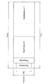
- FIG. 3 is a diagram illustrating an example of a frame configuration of a broadcast signal.
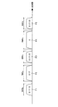
- FIG. 3 is a diagram for describing an outline of a channel scan.
- FIG. 9 is a diagram for describing a flow of a channel scan process.
- FIG. 3 is a diagram for explaining an example of a frame configuration of a broadcast signal according to the embodiment.
- FIG. 1 is a block diagram illustrating an example of a configuration of a signal processing system 10 according to a first embodiment.
- FIG. 3 is a block diagram illustrating a functional configuration example of a receiving circuit 100 according to the first embodiment.
- FIG. 3 is a block diagram illustrating a functional configuration example of a demodulation circuit 200 according to the first embodiment.
- FIG. 4 is a diagram for explaining an example of a flow of a process related to channel scanning using signal bandwidth information by the signal processing system 10.
- FIG. 9 is a block diagram illustrating a functional configuration example of a demodulation circuit 200 according to a second embodiment.
- the receiver In order for the receiver to receive the broadcast signal of the television, first, the band of each channel included in the broadcast signal needs to be set. However, since the band is different for each country or region, first, the receiver performs a channel scan to check the band of a receivable signal.
- the channel scan refers to confirming whether or not a signal of a channel can be received in a predetermined band, and setting a frequency band of a signal whose reception has been normally completed in a receiver.
- FIG. 1 is a diagram showing an example of a frame configuration of a broadcast signal.
- FIG. 1 shows a frame configuration of DVB-T2 (Digital Video Broadcasting-Terrestrial), which is a standard of terrestrial digital television broadcasting, as an example.
- DVB-T2 Digital Video Broadcasting-Terrestrial
- Data1 to Datan are payloads.
- the preambles P1 and P2 do not include information on the frequency bandwidth of the channel. Therefore, even if the receiver receives the preambles P1 and P2, it cannot confirm the bandwidth of the signal of each channel. Therefore, at the time of channel scanning, the receiver needs to confirm, one by one, whether or not a channel signal can be received with a bandwidth that is a candidate.
- FIG. 2 is a diagram for explaining the outline of the channel scan.
- FIG. 2 shows signals F1 to F5 of each channel.
- the frequency bandwidths of the channel signals F1 to F5 are respectively set.
- the receiver attempts to receive the signal F1.
- the receiver executes a reception process of the channel signal F1 with a bandwidth of 8 MHz, and confirms that the channel signal F1 cannot be normally received.
- the receiver executes the reception process of the channel signal F1 with a bandwidth of 7 MHz, and confirms that the channel signal F1 cannot be received normally.
- the receiver executes the reception process of the signal F1 of the channel with the bandwidth of 6 MHz, and confirms that the reception process can be performed normally.
- the receiver performs the above-described operation, and confirms that the bandwidth of the channel signal F1 is 6 MHz.
- the receiver performs the same operation for the channel signals F2 to F5, and confirms that the signals are 7 MHz, 6 MHz, 8 MHz, and 6 MHz, respectively.
- the confirmation as to whether or not reception is possible in the above-mentioned candidate bandwidth is performed at predetermined frequency intervals.
- the receiver confirms whether the signal can be received at a value higher by a predetermined frequency than the frequency of the channel signal F1 after the completion of the confirmation at the frequency of the channel signal F1. Therefore, in the case of the example of FIG. 2, the receiver checks the bandwidth of the channel signal F2 after checking the bandwidth of the channel signal F1.
- FIG. 3 is a diagram for explaining the flow of the channel scan process.
- the receiver sets a signal bandwidth of a channel to be received (S1201).
- the receiver calculates a frequency shift amount based on the setting (S1202).
- the receiver selects an unnecessary frequency band to be removed from the broadcast signal based on the setting (S1203).
- the receiver selects the sampling rate of the broadcast signal after conversion into the baseband signal based on the setting (S1204).
- the receiver determines whether the reception of the channel signal can be normally completed within a predetermined time (S1205). If the reception of the signal of the channel by the receiver is normally completed within a predetermined time (S1205: YES), the band of the signal whose reception has been completed is stored in the recording medium as a list. If the reception of the channel signal by the receiver has not been completed normally within a predetermined time (S1205: NO), whether or not it has been confirmed whether the reception of the channel signal in all of the candidate bandwidths has been confirmed. Is determined (S1207).
- the receiver separates the bandwidth of the signal of the channel to be tried to receive. (S1208), and returns to step S1202.
- the operation ends.
- the receiver can set the frequency band of the signal of the channel by confirming whether or not reception is possible in the bandwidths listed as candidates. However, for each signal, it is necessary for each bandwidth to check whether each signal can be received in a bandwidth listed as a candidate.
- a channel scan can be performed using signal bandwidth information indicating a bandwidth of a channel signal. .
- signal bandwidth information indicating a bandwidth of a channel signal.
- FIG. 4 is a diagram illustrating an example of a frame configuration of a broadcast signal according to the present embodiment.
- FIG. 4 shows a frame configuration example corresponding to the ATSC (Advanced Television Systems Comittee) 3.0 standard as an example.
- ATSC Advanced Television Systems Comittee
- a bit string called Bootstrap is present at the head further than the preamble.
- the signal processing circuit according to the present embodiment can detect signal bandwidth information included in Bootstrap.
- the signal bandwidth information refers to information indicating a bandwidth of a channel signal. Further, the signal bandwidth information may be included in a predetermined frequency band.
- the receiver detects 2-system data ⁇ system_bandwidth ⁇ included in an area called Bootstrap.
- ⁇ System_bandwidth ⁇ includes signal bandwidth information indicating the bandwidth of the signal of the channel including the detected Bootstrap. Note that the signal bandwidth is any of 6 MHz, 7 MHz, and 8 MHz in the case of the ATSC 3.0 standard.
- the bootstrap bandwidth is always a fixed value of 4.5 MHz. Therefore, at the time of channel scanning, the receiver can confirm the bandwidth of the channel signal by initially setting the bandwidth of 4.5 MHz which is the bandwidth of Bootstrap.
- ⁇ system_bandwidth ⁇ that is 2-bit data
- ⁇ 00 ⁇ indicates 6 MHz
- ⁇ 01 ⁇ indicates 7 MHz
- ⁇ 10 ⁇ indicates 8 MHz
- ⁇ 11 ⁇ indicates greater than 8 MHz.
- the signal processing circuit can detect the above-described signal bandwidth information and execute a channel scan based on the signal bandwidth information. According to such a function, the time required for channel scanning can be reduced.
- the signal processing system according to the present embodiment and the signal processing system according to the present embodiment will mainly be described as an example in which the signal processing system according to the present embodiment receives a broadcast signal corresponding to the ATSC 3.0 standard. Will be described. Note that the signal processing according to the present embodiment is not limited to being applied to the ATSC 3.0 standard, but can be applied to any standard that can have signal bandwidth information.
- FIG. 5 is a block diagram illustrating an example of a configuration of the signal processing system 10 according to the present embodiment.
- the signal processing system 10 includes, for example, a reception circuit 100, a demodulation circuit 200, a processing circuit 300, and a processor 400.
- the receiving circuit 100 is a circuit having a function of receiving a broadcast signal. Further, the receiving circuit 100 extracts a signal of a preset frequency from the received broadcast signal, and performs analog-to-digital conversion on the signal.
- the demodulation circuit 200 is a signal processing circuit having a function of demodulating a broadcast signal received by the reception circuit 100. Further, the demodulation circuit 200 detects signal bandwidth information from the broadcast signal. Further, the demodulation circuit 200 specifies the bandwidth of the channel signal.
- the processing circuit 300 is a circuit having a function of processing the broadcast signal demodulated by the demodulation circuit 200.
- the processing circuit 300 converts, for example, a broadcast signal converted into a digital signal by the demodulation circuit 200 into an analog signal.
- Examples of the process for the demodulated broadcast signal include, for example, a display control process for displaying an image on a display screen of a display device, an audio output process for outputting audio from an audio output device, and the like. Any processing that can be performed on the information is included.
- the processor 400 is an external processor having a function of performing a channel scan based on the signal bandwidth information received from the demodulation circuit 200.
- the processor 400 may generate scan information based on the signal bandwidth information, and transmit the scan information to the demodulation circuit 200.
- the scan information refers to information for specifying a target bandwidth for performing a channel scan.
- the processor 400 may execute the channel scan at a predetermined frequency interval.
- the signal processing system 10 can receive a broadcast signal, demodulate the broadcast signal, and process the demodulated broadcast signal. Further, the signal processing system 10 can detect signal bandwidth information and execute a channel scan based on the detected signal bandwidth information.
- the signal processing system includes, for example, a ROM (Read Only Memory; not shown), a RAM (Random Access Memory) (not shown), a recording medium (not shown), a display device (not shown), A part or all of a voice output device (not shown), an operation device (not shown), and a communication device (not shown) may be provided. Further, the signal processing system according to the present embodiment can have a configuration according to an application example of a processing device according to the present embodiment described later.
- the processor 400 is configured by an arithmetic circuit such as an MPU (Micro Processing Unit).
- MPU Micro Processing Unit
- a ROM (not shown) stores programs used by the processor 400 and control data such as operation parameters.
- the RAM (not shown) temporarily stores a program executed by the processor 400 and the like.
- the recording medium is a storage unit included in the signal processing system according to the present embodiment, and includes, for example, data related to signal processing in the demodulation circuit 200, data related to signal processing in the processing circuit 300, various applications, and the like. Of various data.
- examples of the recording medium (not shown) include a nonvolatile memory such as a flash memory.
- the signal processing system 10 illustrated in FIG. 5 for example, one or both of the demodulation circuit 200 and the processing circuit 300 may include a recording medium (not illustrated).
- the signal processing system 10 according to the present embodiment does not include a recording medium (not shown), and various data such as data related to the signal processing according to the present embodiment is stored in the signal processing system 10 according to the present embodiment. It may be stored in an external recording medium.
- the display device displays various images, such as images related to the results of the channel scan, on the display screen.
- Examples of the display device (not shown) include a liquid crystal display and an organic EL display.
- the display device may be a device capable of displaying and operating, such as a touch panel.
- the audio output device (not shown) outputs various audios, for example, audio (including music) indicating the content of the channel scan and audio (including music) indicated by the broadcast signal.
- audio output device (not shown) is a speaker.
- the operation device is a device that can be operated by a user of the signal processing system 10 according to the present embodiment.
- Examples of the operation device (not shown) include a button, a direction key, a rotary selector such as a jog dial, or a combination thereof.
- the communication device is a communication unit included in the signal processing system according to the present embodiment, and plays a role of performing wireless or wired communication with an external device.
- Examples of the communication device (not shown) include a communication antenna and an RF (Radio Frequency) circuit (wireless communication), an IEEE 802.15.1 port and a transmission / reception circuit (wireless communication), an IEEE 802.11 port and a transmission / reception circuit (wireless communication). Communication) or a LAN (Local Area Network) terminal and a transmission / reception circuit (wired communication).
- FIG. 6 is a block diagram illustrating a functional configuration example of the receiving circuit 100 according to the present embodiment.
- the receiving circuit 100 according to the present embodiment includes an RF unit 102 and an AD conversion unit 104.
- the RF unit 102 has a function of receiving a broadcast signal and removing unnecessary frequency components from the received broadcast signal. Further, the RF unit 102 receives scan information and RF information from a register 206 described later. Further, the RF unit 102 calculates a frequency shift amount using the RF information. Here, the RF information is used by the RF unit 102 to calculate a frequency shift amount when the received broadcast signal is converted into a baseband signal in the IFBB conversion unit 202 of the demodulation circuit 200 described below. Note that the RF unit 102 transmits the calculated frequency shift amount to the AD conversion unit 104, which will be described later, in addition to the broadcast signal.
- the RF unit 102 includes an antenna for receiving a broadcast signal.
- the antenna is configured by an antenna having an arbitrary configuration such as a dipole antenna, a monopole antenna, a chip antenna, or a pattern antenna, and receives a radio wave on which a broadcast signal is carried.
- the RF unit 102 includes a filter that removes unnecessary frequency components from the received broadcast signal.
- the band of the frequency to be removed is selected based on the scan information.
- the filter is configured by an arbitrary filter such as a low-pass filter and a band-pass filter.
- the RF unit 102 includes an amplifier.
- the amplifier is configured by an arbitrary amplifier such as an LNA (Low Noise Amplifier) and amplifies a signal transmitted from the filter.
- LNA Low Noise Amplifier
- the AD conversion unit 104 has a function of converting a broadcast signal that is an analog signal transmitted from the RF unit 102 into a digital signal.
- the configuration of the receiving circuit 100 is not limited to the above example.
- the receiving circuit 100 can have any configuration capable of receiving a broadcast signal transmitted by radio waves, for example.
- FIG. 7 is a block diagram illustrating a functional configuration example of the demodulation circuit 200 according to the present embodiment.
- the demodulation circuit 200 according to the present embodiment includes an IFBB conversion unit 202, an information detection unit 204, a register 206, a demodulation unit 208, and an error correction processing unit 210.
- the IFBB conversion unit 202 has a function of converting a broadcast signal received from the receiving circuit 100 into an IF (Intermediate Frequency) signal, and further converting the broadcast signal converted into an IF signal into a BB (BaseBand) signal. Have. Note that the IFBB conversion unit 202 may directly convert a broadcast signal received from the receiving circuit 100 into a BB signal.
- the IFBB conversion unit 202 includes a mixer. A signal transmitted from the amplifier and a signal of a predetermined frequency generated by an oscillator (not shown) are input to the mixer, and the mixer converts the signal transmitted from the amplifier into an IF signal.
- the information detection unit 204 has a function of detecting signal bandwidth information indicating a bandwidth of a channel signal from a broadcast signal.
- the information detecting unit 204 has a function of transmitting the detected signal bandwidth information to the processor 400 via the register 206 described later.
- the information detection unit 204 detects 2-bit data ⁇ system_bandwidth ⁇ included in an area called Bootstrap. Note that the information detection unit 204 transmits ⁇ system_bandwidth ⁇ , which is detected signal bandwidth information, to the processor 400 via a register 206 described later.
- the register 206 has a function of storing information related to channel scanning. Further, the register 206 receives the signal bandwidth information from the information detecting unit 204 and transmits the signal bandwidth information to the processor 400. For example, in the case of the ATSC 3.0 standard, the register 206 receives the above-described ⁇ system_bandwidth ⁇ data from the information detection unit 204 and transmits the data to the processor 400.
- the register 206 receives the scan information and the RF information from the processor 400.
- the transmission and reception of the above-described various information between the register 206 and the processor 400 may be performed via an interface such as I2C (I-squared-C).
- the register 206 has a function of transmitting scan information and RF information to the receiving circuit 100 and transmitting scan information to the IFBB conversion unit 202.
- the demodulation unit 208 has a function of demodulating a broadcast signal transmitted from the information detection unit 204. Specifically, the demodulation unit 208 has a function of executing, for example, a fast Fourier transform process and an equalization process using an equalizer.
- the error correction processing unit 210 has a function of performing error correction on a broadcast signal demodulated by the demodulation unit 208. Further, the error correction processing unit 210 may execute interleaving or data stream processing. Further, the error correction processing unit 210 transmits a broadcast signal to the processing circuit 300 after performing predetermined processing such as error correction on the broadcast signal.
- the functional configuration example of the demodulation circuit 200 has been described above. Note that the function of the demodulation circuit 200 is not limited to the example described above. For example, the demodulation circuit 200 does not need to have any components other than the information detection unit 204. The components of the demodulation circuit 200 other than the information detection unit 204 may be included in another circuit, for example, the reception circuit 100 or the processing circuit 300.
- the demodulation circuit 200 may include part or all of the configuration of the reception circuit 100. That is, in the signal processing system according to the present embodiment, the demodulation circuit 200 shown in FIG. 7 can further have a part or all of the functions of the reception circuit 100 shown in FIG. When the demodulation circuit 200 further has a part or all of the functions of the reception circuit 100, part or all of the configuration of the reception circuit 100 included in the demodulation circuit 200 functions as a reception unit in the demodulation circuit 200.
- the demodulation circuit 200 includes, for example, an "IC (Integrated Circuit) chip including one or more processors and integrated with various circuits for realizing the functions of the demodulation circuit 200". It is needless to say that the demodulation circuit 200 does not have to be realized in the form of an IC chip.
- IC Integrated Circuit
- FIG. 8 is a diagram for explaining an example of a flow of a process related to channel scanning using signal bandwidth information by the signal processing system 10.
- the register 206 sets, as an initial setting, the RF unit 102 and the IFBB conversion unit 202 to a detectable bandwidth of the signal bandwidth information of the signal of the channel that the signal processing system 10 attempts to receive.
- the scan information and the RF information are transmitted to the RF unit 102 as described above (S1001).
- the RF unit 102 receives the RF information, and calculates a frequency shift amount based on the RF information (S1002). Further, the RF unit 102 receives the scan information and selects an unnecessary frequency band to be removed from the broadcast signal based on the scan information (S1003).
- the IFBB conversion unit 202 receives the scan information and selects a sampling rate of the broadcast signal after conversion into the baseband signal based on the scan information (S1004).
- the information detection unit 204 determines whether or not the signal bandwidth information is detected within a predetermined time (S1005). If the information detection unit 204 does not detect the signal bandwidth information within the predetermined time (S1005: NO), the channel scan is executed with the bandwidth preset in the register 206, or the process ends. On the other hand, when the information detection unit 204 detects the signal bandwidth information within a predetermined time (S1005: YES), the information detection unit 204 transmits the signal bandwidth information to the processor 400 via the register 206, and The 400 generates scan information based on the signal bandwidth information, and transmits the scan information to the register 206 (S1006).
- the RF unit 102 receives the RF information and calculates the frequency shift amount again based on the RF information (S1007).
- the RF unit 102 receives the scan information generated by the processor 400, and selects an unnecessary frequency band to be removed from the broadcast signal based on the scan information (S1008).
- the IFBB conversion unit 202 receives the scan information generated by the processor 400, and selects a sampling rate of the broadcast signal converted into a baseband signal based on the scan information (S1009).
- the demodulation circuit 200 determines whether the reception of the channel signal is completed normally within a predetermined time (S1010).
- the demodulation circuit 200 If the demodulation circuit 200 has successfully received the signal of the channel within a predetermined time (S1010: YES), the demodulation circuit 200 stores the band of the received signal as a list in a recording medium (not shown). If the demodulation circuit 200 has not successfully received the signal of the channel within the predetermined time (S1010: NO), the process ends.
- each processing other than the above-described processing of the RF unit 102 may be executed by either hardware or external firmware.
- FIG. 9 is a block diagram illustrating a functional configuration example of the demodulation circuit 200 according to the present embodiment.
- FIG. 9 further includes a band control unit 212.
- the band control unit 212 corresponds to the processor 400 according to the first embodiment. Specifically, the band control unit 212 according to the present embodiment has a function of executing a channel scan based on the bandwidth of a channel signal. Specifically, the band control unit 212 generates scan information based on the signal bandwidth information received from the information detection unit 204, and transmits the scan information to the RF unit 102 and the IFBB conversion unit 202 of the receiving circuit. .
- the process related to channel scan is as follows.
- the information detection unit 204 transmits the signal bandwidth information to the bandwidth control unit 212.
- Band control section 212 generates scan information based on the signal bandwidth information, and transmits the generated scan information to receiving circuit 100 and IFBB conversion section 202.
- the band control unit 212 When the information detection unit 204 does not detect the signal bandwidth information, the band control unit 212 performs the channel scan with the bandwidth set in the band control unit 212 in advance. Specifically, when the information detection unit 204 does not detect the signal bandwidth information from the channel signal, the band control unit 212 generates the scan information based on the bandwidth set in the band control unit 212 in advance. , And transmits the generated scan information to the receiving circuit 100 and the IFBB conversion unit 202.
- the demodulation circuit 200 since the demodulation circuit 200 according to the present embodiment includes the band control unit 212, it is not necessary to transmit and receive the signal bandwidth information and the scan information via the register 206 and the processor 400. Therefore, the time required for channel scanning can be further reduced.
- the signal processing circuit and the signal processing system can check the bandwidth of the channel signal using the signal bandwidth information included in the broadcast signal. According to such a function, the time required for channel scanning can be reduced.
- each step shown in each of the above-mentioned flowcharts does not necessarily need to be processed in chronological order in the order described in the flowchart. That is, each step may be processed in an order different from the order described in the flowchart, or may be processed in parallel.
- an information detection unit that detects signal bandwidth information indicating a bandwidth of a channel signal, With The signal bandwidth information is used for performing a channel scan, Signal processing circuit.
- the information detection unit from a predetermined frequency band of the broadcast signal, detects the signal bandwidth information, The signal processing circuit according to (1).
- the channel scan is executed by an external processor based on a bandwidth of a signal of the channel.
- the channel scan is performed at predetermined frequency intervals, The signal processing circuit according to any one of the above (1) to (3).
- the signal processing circuit further comprising a band control unit that performs a channel scan based on the bandwidth of the signal of the channel indicated by the signal bandwidth information, The signal processing circuit according to (1) or (2).
- the band controller based on the signal bandwidth information, transmits scan information specifying a target bandwidth for performing the channel scan to the receiving circuit, The signal processing circuit according to (5).
- the band control unit when the signal bandwidth information is not detected from the broadcast signal, performs a channel scan with a preset bandwidth, The signal processing circuit according to (5) or (6).
- the information detection unit detects the signal bandwidth information from a Bootstrap corresponding to the Advanced Television Systems Committee (ATSC) 3.0 standard.
- the signal processing circuit according to any one of the above (1) to (7).
- a signal processing circuit A processor, Has, The signal processing circuit, from the broadcast signal received by a receiving circuit that receives a broadcast signal, an information detection unit that detects signal bandwidth information related to the bandwidth of the channel signal, With The signal bandwidth information is used for performing a channel scan in the processor, Signal processing system.
- the processor based on the signal bandwidth information, transmits scan information specifying a target bandwidth for performing the channel scan to the receiving circuit, The signal processing system according to (9).
- the processor transmits the scan information to the receiving circuit via a register, The signal processing system according to (10).
Landscapes
- Engineering & Computer Science (AREA)
- Signal Processing (AREA)
- Multimedia (AREA)
- Computer Networks & Wireless Communication (AREA)
- Business, Economics & Management (AREA)
- General Business, Economics & Management (AREA)
- Databases & Information Systems (AREA)
- Circuits Of Receivers In General (AREA)
- Two-Way Televisions, Distribution Of Moving Picture Or The Like (AREA)
Abstract
放送信号を受信する受信回路(100)により受信された放送信号から、チャンネルの信号の帯域幅を示す信号帯域幅情報を検出する情報検出部(204)、を備え、信号帯域幅情報は、チャンネルスキャンの実行に用いられる、信号処理回路、が提供される。
Description
本開示は、信号処理回路および信号処理システムに関する。
近年、デジタルテレビ放送に関する種々の技術が開発されている。例えば、下記の非特許文献1に記載の規格化された技術が挙げられる。
ATSC Standard: A/321, System Discovery and Signaling(https://www.atsc.org/wp-content/uploads/2016/03/A321-2016-System-Discovery-and-Signaling.pdf)
受信機は、デジタルテレビに関する放送信号を受信する際に、まず放送信号に含まれるチャンネルの信号の周波数帯域を設定する。その際、受信機は、所定の帯域幅でチャンネルの信号が受信可能であるか否かを確認する。
しかしながら、既存の機器において、上述した確認は候補として挙げられる帯域幅でひとつずつ行われている。そのため、信号の受信が可能であるか否かを確認する時間が当該帯域幅毎に必要となる。
本開示では、チャンネルスキャンに要する時間を短縮することが可能な信号処理回路、および信号処理システムを提案する。
本開示によれば、放送信号を受信する受信回路により受信された前記放送信号から、チャンネルの信号の帯域幅を示す信号帯域幅情報を検出する情報検出部、を備え、前記信号帯域幅情報は、チャンネルスキャンの実行に用いられる、信号処理回路が提供される。
また、本開示によれば、信号処理回路と、プロセッサと、を有し、前記信号処理回路は、放送信号を受信する受信回路により受信された前記放送信号から、チャンネルの信号の帯域幅に係る信号帯域幅情報を検出する情報検出部、を備え、前記信号帯域幅情報は、前記プロセッサにおけるチャンネルスキャンの実行に用いられる、信号処理システムが提供される。
本開示によれば、チャンネルスキャンに要する時間を短縮することが可能となる。
なお、上記の効果は必ずしも限定的なものではなく、上記の効果とともに、または上記の効果に代えて、本明細書に示されたいずれかの効果、または本明細書から把握され得る他の効果が奏されてもよい。
以下に添付図面を参照しながら、本開示の好適な実施の形態について詳細に説明する。なお、本明細書及び図面において、実質的に同一の機能構成を有する構成要素については、同一の符号を付することにより重複説明を省略する。
なお、説明は以下の順序で行うものとする。
1.背景および概要
2.第1の実施形態
2-1.信号処理システム10の構成例
2-2.受信回路100の構成例および処理の一例
2-3.復調回路200の構成例および処理の一例
2-4.処理の流れ
3.第2の実施形態
4.まとめ
1.背景および概要
2.第1の実施形態
2-1.信号処理システム10の構成例
2-2.受信回路100の構成例および処理の一例
2-3.復調回路200の構成例および処理の一例
2-4.処理の流れ
3.第2の実施形態
4.まとめ
<1.背景および概要>
まず、本発明の背景および概要について説明する。受信機は、テレビの放送信号を受信するために、まず当該放送信号に含まれる各々のチャンネルの帯域が設定されている必要がある。しかし、当該帯域は国や地域毎に異なるため、最初に、受信機は、チャンネルスキャンを実行し、受信が可能な信号の帯域を確認する。ここで、チャンネルスキャンとは、所定の帯域でチャンネルの信号の受信が可能である否かを確認し、受信が正常に完了した信号の周波数帯域を受信機に設定することをいう。
まず、本発明の背景および概要について説明する。受信機は、テレビの放送信号を受信するために、まず当該放送信号に含まれる各々のチャンネルの帯域が設定されている必要がある。しかし、当該帯域は国や地域毎に異なるため、最初に、受信機は、チャンネルスキャンを実行し、受信が可能な信号の帯域を確認する。ここで、チャンネルスキャンとは、所定の帯域でチャンネルの信号の受信が可能である否かを確認し、受信が正常に完了した信号の周波数帯域を受信機に設定することをいう。
図1は、放送信号のフレーム構成の一例を示す図である。図1において、一例として地上デジタルテレビジョン放送の規格であるDVB-T2(Digital Video Broadcasting - Terrestrial)のフレーム構成が示されている。ここで、プリアンブルP1、P2示されている。また、Data1~nはペイロードである。例えば当該規格の場合、プリアンブルP1、P2には、チャンネルの周波数帯域幅の情報が含まれていない。従って、受信機は、プリアンブルP1、P2を受信した場合でも、各々のチャンネルの信号の帯域幅を確認することができない。そのため、受信機は、チャネルスキャンの際には、候補として挙げられる帯域幅でチャンネルの信号が受信可能であるか否かを、ひとつずつ確認する必要がある。
図2は、チャンネルスキャンの概要を説明するための図である。図2には、各々のチャンネルの信号F1~F5が示されている。図2において、チャンネルの信号F1~F5の周波数帯域幅は、各々設定されている。
以下具体的に説明する。まず、受信機は、信号F1の受信を試みる。次に、受信機は、帯域幅8MHzでチャンネルの信号F1の受信処理を実行し、チャンネルの信号F1を正常に受信できないことを確認する。
次に、受信機は、帯域幅7MHzでチャンネルの信号F1の受信処理を実行し、チャンネルの信号F1を正常に受信できないことを確認する。次に、受信機は、帯域幅6MHzでチャンネルの信号F1の受信処理を実行し、正常に受信処理できることを確認する。
受信機が上述の作業を実行することにより、チャンネルの信号F1の帯域幅が6MHzであることが確認される。受信機は、チャンネルの信号F2~F5に関しても同様の作業を実行し、各々7MHz、6MHz、8MHz、6MHzであることを確認する。なお、上述した候補として挙げられる帯域幅で受信可能か否かの確認は、所定の周波数間隔で実行される。例えば、受信機は、チャンネルの信号F1の周波数での確認が完了した後、チャンネルの信号F1の周波数よりも所定の周波数だけ高い値で、信号が受信可能であるか否かを確認する。従って、図2の一例の場合、受信機は、チャンネルの信号F1の帯域幅の確認が完了後、チャンネルの信号F2の帯域幅の確認を行う。
次に、チャンネルスキャンの処理の流れについて説明する。図3は、チャンネルスキャンの処理の流れを説明するための図である。図3を参照すると、まず、受信機は、初期設定として、受信を試みる対象のチャンネルの信号の帯域幅を設定する(S1201)。次に、受信機は、当該設定に基づいて、周波数シフト量を算出する(S1202)。また、受信機は、当該設定に基づいて、放送信号から除去する不要な周波数帯域を選択する(S1203)。また、受信機は、当該設定に基づいて、ベースバンド信号へ変換後の放送信号のサンプリングレートを選択する(S1204)。
次に、受信機は、チャンネルの信号を所定の時間内に正常に受信完了できるか否かを判定する(S1205)。受信機によるチャンネルの信号の受信が所定の時間内に正常に完了した場合(S1205:YES)、受信が完了した信号の帯域をリストとして記録媒体へ保存する。受信機によるチャンネルの信号の受信が所定の時間内に正常に完了しなかった場合(S1205:NO)、候補として挙げられる全ての帯域幅でのチャンネルの信号の受信ができるか確認したか否かを判定する(S1207)。一方候補として挙げられる全ての帯域幅でのチャンネルの信号の受信ができるか否かを確認していない場合(S1207:NO)、受信機は、受信を試みる対象のチャンネルの信号の帯域幅を別の値に設定し(S1208)、ステップS1202へ戻る。一方、候補として挙げられる全ての帯域幅でのチャンネルの信号の受信ができるか否かを確認した場合(S1207:YES)、動作は終了する。
このように、受信機が、候補として挙げられる帯域幅での受信が可能か否かを確認することにより、チャンネルの信号の周波数帯域を設定することが可能となる。しかし、各々の信号に対して、候補として挙げられる帯域幅で受信が可能か否かを、ひとつずつ確認する時間が当該帯域幅毎に必要となる。
本開示の一実施形態に係る技術思想は、上記の点に着目して発想されたものであり、チャンネルの信号の帯域幅を示す信号帯域幅情報を用いて、チャンネルスキャンを実行することができる。係る機能により、チャンネルスキャンに要する時間を短縮することが可能である。
図4は、本実施形態に係る放送信号のフレーム構成の一例を説明するための図である。図4には、一例としてATSC(Advanced Television Systems Committee)3.0規格に対応するフレーム構成例が示されている。図2に示されているように、ATSC3.0規格のフレーム構成では、プリアンブルよりもさらに先頭の部分に、Bootstrapと呼ばれるビット列が存在する。本実施形態に係る信号処理回路は、Bootstrapに含まれる信号帯域幅情報を検出することが可能である。ここで、信号帯域幅情報とは、チャンネルの信号の帯域幅を示す情報をいう。また、信号帯域幅情報は、所定の周波数帯域に含まれてよい。
ATSC3.0規格の場合、受信機は、Bootstrapと呼ばれる領域に含まれる{system_bandwidth}という2ビットのデータを検出する。{system_bandwidth}には、検出されたBootstrapが含まれるチャンネルの信号の帯域幅を示す信号帯域幅情報が含まれている。なお、信号の帯域幅は、ATSC3.0規格の場合、6MHz、7MHz、8MHzのいずれかである。
ここで、Bootstrapの帯域幅は常に固定の値の4.5MHzである。そのため、受信機は、チャネルスキャンの際に、まずBootstrapの帯域幅である4.5MHzを帯域幅として初期設定することで、チャンネルの信号の帯域幅を確認することができる。
なお、2ビットのデータである{system_bandwidth}に関して、{00}は6MHz、{01}は7MHz、{10}は8MHz、{11}は8MHzより大きい、を示す。
このように、チャンネルスキャンの際に、信号の帯域幅を最初に取得することで、候補として挙げられる帯域幅で受信が完了するか否かをひとつずつ確認する必要が無くなる。
本実施形態に係る信号処理回路は、上述した信号帯域幅情報を検出し、当該信号帯域幅情報に基づいて、チャンネルスキャンを実行することが可能である。係る機能によれば、チャンネルスキャンに要する時間を短縮することができる。
以下本実施形態に係る信号処理システムが、ATSC3.0規格に対応する放送信号を受信する場合を主に例に挙げながら、本実施形態に係る信号処理回路、および本実施形態に係る信号処理システムについて説明していく。なお、本実施形態に係る信号処理は、ATSC3.0規格に適用されることに限らず、信号帯域幅情報を有することが可能な任意の規格に、適用することが可能である。
<2.第1の実施形態>
(2-1.信号処理システム10の構成例)
図5は、本実施形態に係る信号処理システム10の構成の一例を示すブロック図である。信号処理システム10は、例えば、受信回路100、復調回路200、処理回路300、およびプロセッサ400を備える。
(2-1.信号処理システム10の構成例)
図5は、本実施形態に係る信号処理システム10の構成の一例を示すブロック図である。信号処理システム10は、例えば、受信回路100、復調回路200、処理回路300、およびプロセッサ400を備える。
受信回路100は、放送信号を受信する機能を有する回路である。また、受信回路100は、受信された放送信号から、予め設定された周波数の信号を抽出し、当該信号に対してアナログデジタル変換を実行する。
復調回路200は、受信回路100が受信した放送信号を復調する機能を有する信号処理回路である。また、復調回路200は、当該放送信号から、信号帯域幅情報を検出する。また、復調回路200は、チャンネルの信号の帯域幅を特定する。
処理回路300は、復調回路200により復調された放送信号を処理する機能を有する回路である。処理回路300は、例えば復調回路200によりデジタル信号に変換された放送信号をアナログ信号に変換する。また、復調された放送信号に対する処理の一例としては、例えば、表示デバイスの表示画面に画像を表示させる表示制御処理や、音声出力デバイスから音声を出力させる音声出力処理など、復調された放送信号に対して行うことが可能な任意の処理が挙げられる。
プロセッサ400は、復調回路200から受信した信号帯域幅情報に基づいて、チャンネルスキャンを実行する機能を有する外部プロセッサである。ここで、プロセッサ400は、信号帯域幅情報に基づいて、スキャン情報を生成し、当該スキャン情報を復調回路200へ送信してもよい。ここで、スキャン情報とは、チャンネルスキャンを実行する対象の帯域幅を指定する情報をいう。
また、プロセッサ400は、所定の周波数間隔でチャンネルスキャンを実行してよい。
信号処理システム10は、図5に示す構成により、放送信号を受信し、当該放送信号を復調し、復調された放送信号を処理することができる。また信号処理システム10は、信号帯域幅情報を検出し、検出した信号帯域幅情報に基づいてチャネルスキャンを実行することができる。
なお、本実施形態に係る信号処理システム10の構成は、図5に示す例に限られない。
本実施形態に係る信号処理システムは、例えば、ROM(Read Only Memory。図示せず)、RAM(Random Access Memory。図示せず)、記録媒体(図示せず)、表示デバイス(図示せず)、音声出力デバイス(図示せず)、操作デバイス(図示せず)、通信デバイス(図示せず)のうちの一部または全部を備えていてもよい。また、本実施形態に係る信号処理システムは、後述する本実施形態に係る処理装置の適用例に応じた構成をとることが可能である。
プロセッサ400は、例えば、MPU(Micro Processing Unit)などの演算回路で構成される。
ROM(図示せず)は、プロセッサ400が使用するプログラムや演算パラメータなどの制御用データを記憶する。RAM(図示せず)は、プロセッサ400により実行されるプログラムなどを一時的に記憶する。
記録媒体(図示せず)は、本実施形態に係る信号処理システムが備える記憶手段であり、例えば、復調回路200における信号処理に係るデータや、処理回路300における信号処理に係るデータ、各種アプリケーションなどの、様々なデータを記憶する。ここで、記録媒体(図示せず)としては、例えば、フラッシュメモリなどの不揮発性メモリなどが挙げられる。なお、図5に示す信号処理システム10では、例えば、復調回路200および処理回路300の一方または双方が、記録媒体(図示せず)を備えていてもよい。また、本実施形態に係る信号処理システム10は、記録媒体(図示せず)を備えず、本実施形態に係る信号処理に係るデータなどの各種データは、本実施形態に係る信号処理システム10の外部の記録媒体に記憶されていてもよい。
表示デバイス(図示せず)は、例えば、チャンネルスキャンの結果に係る画像などの、様々な画像を、表示画面に表示する。表示デバイス(図示せず)としては、例えば、液晶ディスプレイや有機ELディスプレイなどが挙げられる。また、表示デバイスは、例えばタッチパネルなど、表示と操作とが可能なデバイスであってもよい。
音声出力デバイス(図示せず)は、例えば、チャンネルスキャンの内容を示す音声(音楽も含む。)や放送信号が示す音声(音楽も含む。)などの、様々な音声を出力する。音声出力デバイス(図示せず)としては、例えばスピーカが挙げられる。
操作デバイス(図示せず)は、本実施形態に係る信号処理システム10の使用者が操作可能なデバイスである。操作デバイス(図示せず)としては、例えば、ボタンや、方向キー、ジョグダイヤルなどの回転型セレクタ、あるいは、これらの組み合わせなどが挙げられる。
通信デバイス(図示せず)は、本実施形態に係る信号処理システムが備える通信手段であり、外部装置と無線または有線で通信を行う役目を果たす。通信デバイス(図示せず)としては、例えば、通信アンテナおよびRF(Radio Frequency)回路(無線通信)や、IEEE802.15.1ポートおよび送受信回路(無線通信)、IEEE802.11ポートおよび送受信回路(無線通信)、あるいはLAN(Local Area Network)端子および送受信回路(有線通信)などが挙げられる。
(2-2.受信回路100の構成例および処理の一例)
次に、本実施形態に係る受信回路100の構成例および処理の一例について説明する。図6は、本実施形態に係る受信回路100の機能構成例を示すブロック図である。図6を参照すると、本実施形態に係る受信回路100は、RF部102およびAD変換部104を備える。
次に、本実施形態に係る受信回路100の構成例および処理の一例について説明する。図6は、本実施形態に係る受信回路100の機能構成例を示すブロック図である。図6を参照すると、本実施形態に係る受信回路100は、RF部102およびAD変換部104を備える。
(RF部102)
本実施形態に係るRF部102は、放送信号を受信し、受信した放送信号から不要な周波数成分を除去する機能を有する。また、RF部102は、後述するレジスタ206からスキャン情報およびRF情報を受信する。また、RF部102は、RF情報を用いて周波数シフト量を算出する。ここで、RF情報とは、後述する復調回路200のIFBB変換部202において、受信された放送信号をベースバンド信号へ変換する際に、周波数シフト量をRF部102が算出するために用いられる。なお、RF部102は、放送信号に加えて、算出された周波数シフト量も後述するAD変換部104へと送信する。
本実施形態に係るRF部102は、放送信号を受信し、受信した放送信号から不要な周波数成分を除去する機能を有する。また、RF部102は、後述するレジスタ206からスキャン情報およびRF情報を受信する。また、RF部102は、RF情報を用いて周波数シフト量を算出する。ここで、RF情報とは、後述する復調回路200のIFBB変換部202において、受信された放送信号をベースバンド信号へ変換する際に、周波数シフト量をRF部102が算出するために用いられる。なお、RF部102は、放送信号に加えて、算出された周波数シフト量も後述するAD変換部104へと送信する。
なお、RF部102は、放送信号を受信するアンテナを備える。アンテナは、例えば、ダイポールアンテナ、モノポールアンテナ、チップアンテナ、あるいはパターンアンテナなどの、任意の構成のアンテナで構成され、放送信号が搬送される電波を受信する。
また、RF部102は、受信された放送信号から不要な周波数成分を除去するフィルタを備える。除去する周波数の帯域は、スキャン情報に基づいて選択される。当該フィルタは、例えば、ローパスフィルタやバンドパスフィルタなどの任意のフィルタで構成されている。また、RF部102は、増幅器を備える。増幅器は、LNA(Low Noise Amplifier)などの任意の増幅器で構成され、フィルタから伝達される信号を増幅する。
(AD変換部104)
本実施形態に係るAD変換部104は、RF部102から送信されたアナログ信号である放送信号を、デジタル信号に変換する機能を有する。
本実施形態に係るAD変換部104は、RF部102から送信されたアナログ信号である放送信号を、デジタル信号に変換する機能を有する。
なお、受信回路100の構成は、上記に示す例に限られない。受信回路100は、例えば、電波で送信される放送信号を受信することが可能な、任意の構成を有することが可能である。
(2-3.復調回路200の構成例および処理の一例)
次に、本実施形態に係る復調回路200の機能構成例について説明する。図7は、本実施形態に係る復調回路200の機能構成例を示すブロック図である。図7を参照すると、本実施形態に係る復調回路200は、IFBB変換部202、情報検出部204、レジスタ206、復調部208、および誤り訂正処理部210を備える。
次に、本実施形態に係る復調回路200の機能構成例について説明する。図7は、本実施形態に係る復調回路200の機能構成例を示すブロック図である。図7を参照すると、本実施形態に係る復調回路200は、IFBB変換部202、情報検出部204、レジスタ206、復調部208、および誤り訂正処理部210を備える。
(IFBB変換部202)
本実施形態に係るIFBB変換部202は、受信回路100から受信した放送信号を、IF(Intermediate Frequency)信号に変換し、さらにIF信号に変換した放送信号をBB(BaseBand)信号に変換する機能を有する。なお、IFBB変換部202は、受信回路100から受信した放送信号を、BB信号へ直接変換してもよい。
本実施形態に係るIFBB変換部202は、受信回路100から受信した放送信号を、IF(Intermediate Frequency)信号に変換し、さらにIF信号に変換した放送信号をBB(BaseBand)信号に変換する機能を有する。なお、IFBB変換部202は、受信回路100から受信した放送信号を、BB信号へ直接変換してもよい。
なお、IFBB変換部202は、ミキサを備える。ミキサには、増幅器から送信される信号と、発振器(図示せず)などにより生成された所定周波数の信号とが入力され、ミキサは、増幅器から送信される信号をIF信号に変換する。
(情報検出部204)
本実施形態に係る情報検出部204は、放送信号からチャンネルの信号の帯域幅を示す信号帯域幅情報を検出する機能を有する。また、情報検出部204は、検出された信号帯域幅情報を後述するレジスタ206を介してプロセッサ400へ送信する機能を有する。
本実施形態に係る情報検出部204は、放送信号からチャンネルの信号の帯域幅を示す信号帯域幅情報を検出する機能を有する。また、情報検出部204は、検出された信号帯域幅情報を後述するレジスタ206を介してプロセッサ400へ送信する機能を有する。
上述したように、情報検出部204は、Bootstrapと呼ばれる領域に含まれる{system_bandwidth}という2ビットのデータを検出する。なお、情報検出部204は、検出された信号帯域幅情報である{system_bandwidth}を後述するレジスタ206を介してプロセッサ400へ送信する。
(レジスタ206)
本実施形態に係るレジスタ206は、チャンネルスキャンに関する情報を保存する機能を有する。また、レジスタ206は、情報検出部204から信号帯域幅情報を受信し、当該信号帯域幅情報をプロセッサ400へ送信する。例えば、レジスタ206は、ATSC3.0規格の場合、上述した{system_bandwidth}データを情報検出部204から受信し、当該データをプロセッサ400へ送信する。
本実施形態に係るレジスタ206は、チャンネルスキャンに関する情報を保存する機能を有する。また、レジスタ206は、情報検出部204から信号帯域幅情報を受信し、当該信号帯域幅情報をプロセッサ400へ送信する。例えば、レジスタ206は、ATSC3.0規格の場合、上述した{system_bandwidth}データを情報検出部204から受信し、当該データをプロセッサ400へ送信する。
また、レジスタ206は、スキャン情報およびRF情報をプロセッサ400から受信する。なお、レジスタ206とプロセッサ400間の上述した種々の情報の送受信は、例えばI2C(I-squared-C)などのインターフェースを介して行われてよい。
また、レジスタ206は、スキャン情報およびRF情報を受信回路100へ、またスキャン情報をIFBB変換部202へ、送信する機能を有する。
(復調部208)
本実施形態に係る復調部208は、情報検出部204から送信された放送信号を復調する機能を有する。具体的には、復調部208は、例えば高速フーリエ変換処理、イラコライザを用いた等化処理を実行する機能を有する。
本実施形態に係る復調部208は、情報検出部204から送信された放送信号を復調する機能を有する。具体的には、復調部208は、例えば高速フーリエ変換処理、イラコライザを用いた等化処理を実行する機能を有する。
(誤り訂正処理部210)
本実施形態に係る誤り訂正処理部210は、復調部208が復調した放送信号に対して誤り訂正を行う機能を有する。また、誤り訂正処理部210は、インタリーブまたはデータストリームの処理を実行してもよい。また、誤り訂正処理部210は、放送信号に対する誤り訂正などの所定の処理を実行後、当該放送信号を処理回路300へ送信する。
本実施形態に係る誤り訂正処理部210は、復調部208が復調した放送信号に対して誤り訂正を行う機能を有する。また、誤り訂正処理部210は、インタリーブまたはデータストリームの処理を実行してもよい。また、誤り訂正処理部210は、放送信号に対する誤り訂正などの所定の処理を実行後、当該放送信号を処理回路300へ送信する。
以上、復調回路200の機能構成例について説明した。なお、復調回路200が有する機能は、上記に示す例に限られない。例えば、復調回路200は、情報検出部204以外の構成要素を有していなくてよい。また、情報検出部204以外の復調回路200の構成要素は、別の回路、例えば受信回路100または処理回路300が有してもよい。
また、復調回路200は、受信回路100の構成の一部または全部を備えていてもよい。つまり、本実施形態に係る信号処理システムでは、図7に示す復調回路200が、図7に示す受信回路100の一部または全部の機能をさらに有することも可能である。復調回路200が受信回路100の一部または全部の機能をさらに有する場合、復調回路200が備える受信回路100の構成の一部または全部は、復調回路200において受信部の役目を果たす。
復調回路200としては、例えば“1または2以上のプロセッサを含み、復調回路200が有する機能を実現するための各種回路が集積されたIC(Integrated Circuit)チップ”が、挙げられる。なお、復調回路200が、ICチップの形態で実現されていなくてもよいことは、言うまでもない。
(2-4.処理の流れ)
以下、信号処理システム10による信号帯域幅情報を利用したチャンネルスキャンに係る処理の流れについて説明していく。図8は、信号処理システム10による信号帯域幅情報を利用したチャンネルスキャンに係る処理の流れの一例について説明するための図である。
以下、信号処理システム10による信号帯域幅情報を利用したチャンネルスキャンに係る処理の流れについて説明していく。図8は、信号処理システム10による信号帯域幅情報を利用したチャンネルスキャンに係る処理の流れの一例について説明するための図である。
図8を参照するとまず、レジスタ206は、RF部102およびIFBB変換部202に、初期設定として、信号処理システム10が受信を試みるチャンネルの信号の信号帯域幅情報を検出可能な帯域幅に設定するようにスキャン情報を、またRF部102にRF情報を送信する(S1001)。次に、RF部102は、RF情報を受信し、当該RF情報に基づいて、周波数シフト量を算出する(S1002)。また、RF部102は、スキャン情報を受信し、当該スキャン情報に基づいて、放送信号から除去する不要な周波数帯域を選択する(S1003)。一方、IFBB変換部202は、スキャン情報を受信し、当該スキャン情報に基づいて、ベースバンド信号へ変換後の放送信号のサンプリングレートを選択する(S1004)。
次に、情報検出部204は、信号帯域幅情報が所定の時間内に検出されるか否かを判定する(S1005)。情報検出部204が信号帯域幅情報を所定の時間内に検出しなかった場合(S1005:NO)、レジスタ206に予め設定された帯域幅でチャンネルスキャンを実行するか、もしくは処理は終了する。一方、情報検出部204が信号帯域幅情報を所定の時間内に検出した場合(S1005:YES)、情報検出部204は、レジスタ206を介して、プロセッサ400へ信号帯域幅情報を送信し、プロセッサ400は、信号帯域幅情報に基づいて、スキャン情報を生成し、当該スキャン情報をレジスタ206へ送信する(S1006)。
次に、RF部102は、RF情報を受信し、当該RF情報に基づいて、周波数シフト量を再び算出する(S1007)。次に、RF部102は、プロセッサ400が生成したスキャン情報を受信し、当該スキャン情報に基づいて、放送信号から除去する不要な周波数帯域を選択する(S1008)。一方、IFBB変換部202は、プロセッサ400が生成したスキャン情報を受信し、当該スキャン情報に基づいて、ベースバンド信号へ変換後の放送信号のサンプリングレートを選択する(S1009)。次に、復調回路200がチャンネルの信号が所定の時間内に正常に受信が完了されるか否かを判定する(S1010)。復調回路200がチャンネルの信号が所定の時間内に正常に受信が完了された場合(S1010:YES)、受信が完了した信号の帯域をリストとして記録媒体(図示せず)へ保存する。復調回路200がチャンネルの信号が所定の時間内に正常に受信が完了しなかった場合(S1010:NO)、処理は終了する。
なお、上述したRF部102の処理(ステップS1002、ステップS1003、ステップS1007、ステップ、S1008)以外の各々の処理は、ハードウェアまたは外部ファームウェアのいずれかにより実行されてよい。
<3.第2の実施形態>
上記では、本開示に係る第1の実施形態について説明した。続いて、本開示に係る第2の実施形態について説明する。基本的に、第1の実施形態の説明と重複する内容は省略し、第1の実施形態との差分について説明する。
上記では、本開示に係る第1の実施形態について説明した。続いて、本開示に係る第2の実施形態について説明する。基本的に、第1の実施形態の説明と重複する内容は省略し、第1の実施形態との差分について説明する。
図9は、本実施形態に係る復調回路200の機能構成例を示すブロック図である。図9には、帯域制御部212をさらに備える。
本実施形態に係る帯域制御部212は、第1の実施形態に係るプロセッサ400に相当する。具体的には、本実施形態に係る帯域制御部212は、チャンネルの信号の帯域幅に基づいて、チャネルスキャンを実行する機能を有する。具体的には、帯域制御部212は、情報検出部204から受信した信号帯域幅情報に基づいて、スキャン情報を生成し、当該スキャン情報を受信回路のRF部102およびIFBB変換部202へ送信する。
チャンネルスキャンに関する処理は以下のような流れとなる。情報検出部204は、放送信号から信号帯域幅情報が検出された場合、当該信号帯域幅情報を帯域制御部212へ送信する。帯域制御部212は、当該信号帯域幅情報に基づいて、スキャン情報を生成し、生成されたスキャン情報を受信回路100およびIFBB変換部202へ送信する。
なお、帯域制御部212は、情報検出部204が信号帯域幅情報を検出しなかった場合、予め帯域制御部212に設定された帯域幅でチャンネルスキャンを実行する。具体的には、帯域制御部212は、情報検出部204がチャンネルの信号から信号帯域幅情報を検出しなかった場合、予め帯域制御部212に設定された帯域幅に基づいてスキャン情報を生成し、生成されたスキャン情報を受信回路100およびIFBB変換部202へ送信する。
このように、本実施形態に係る復調回路200が帯域制御部212を備えることにより、レジスタ206およびプロセッサ400を介した信号帯域幅情報およびスキャン情報の送受信を行う必要が無くなる。そのため、チャンネルスキャンに要する時間をさらに短縮することが可能となる。
<4.まとめ>
以上で説明したように、信号処理回路および信号処理システムは、放送信号に含まれる信号帯域幅情報を用いて、チャンネルの信号の帯域幅を確認することができる。係る機能によれば、チャンネルスキャンに要する時間を短縮することが可能となる。
以上で説明したように、信号処理回路および信号処理システムは、放送信号に含まれる信号帯域幅情報を用いて、チャンネルの信号の帯域幅を確認することができる。係る機能によれば、チャンネルスキャンに要する時間を短縮することが可能となる。
以上、添付図面を参照しながら本開示の好適な実施形態について詳細に説明したが、本開示の技術的範囲はかかる例に限定されない。本開示の技術分野における通常の知識を有する者であれば、請求の範囲に記載された技術的思想の範疇内において、各種の変更例または修正例に想到し得ることは明らかであり、これらについても、当然に本開示の技術的範囲に属するものと了解される。
例えば、上記の各フローチャートに示した各ステップは、必ずしもフローチャートとして記載された順序に沿って時系列に処理する必要はない。すなわち、各ステップは、フローチャートとして記載した順序と異なる順序で処理されても、並列的に処理されてもよい。
また、本明細書に記載された効果は、あくまで説明的または例示的なものであって限定的ではない。つまり、本開示に係る技術は、上記の効果とともに、または上記の効果に代えて、本明細書の記載から当業者には明らかな他の効果を奏しうる。
なお、以下のような構成も本開示の技術的範囲に属する。
(1)
放送信号を受信する受信回路により受信された前記放送信号から、チャンネルの信号の帯域幅を示す信号帯域幅情報を検出する情報検出部、
を備え、
前記信号帯域幅情報は、チャンネルスキャンの実行に用いられる、
信号処理回路。
(2)
前記情報検出部は、前記放送信号の所定の周波数帯域から、前記信号帯域幅情報を検出する、
前記(1)に記載の信号処理回路。
(3)
前記チャンネルスキャンは、前記チャンネルの信号の帯域幅に基づいて、外部プロセッサにより実行される、
前記(1)または(2)に記載の信号処理回路。
(4)
前記チャンネルスキャンは、所定の周波数間隔で実行される、
前記(1)~(3)のいずれかに記載の信号処理回路。
(5)
前記信号帯域幅情報が示す前記チャンネルの信号の帯域幅に基づいて、チャンネルスキャンを実行する帯域制御部をさらに備える、
前記(1)または(2)に記載の信号処理回路。
(6)
前記帯域制御部は、前記信号帯域幅情報に基づいて、前記チャンネルスキャンを実行する対象の帯域幅を指定するスキャン情報を前記受信回路へ送信する、
前記(5)に記載の信号処理回路。
(7)
前記帯域制御部は、前記放送信号から前記信号帯域幅情報が検出されなかった場合、予め設定された帯域幅でチャンネルスキャンを実行する、
前記(5)または(6)に記載の信号処理回路。
(8)
前記情報検出部は、ATSC(Advanced Television Systems Committee)3.0規格に対応するBootstrapから前記信号帯域幅情報を検出する、
前記(1)~(7)のいずれかに記載の信号処理回路。
(9)
信号処理回路と、
プロセッサと、
を有し、
前記信号処理回路は、放送信号を受信する受信回路により受信された前記放送信号から、チャンネルの信号の帯域幅に係る信号帯域幅情報を検出する情報検出部、
を備え、
前記信号帯域幅情報は、前記プロセッサにおけるチャンネルスキャンの実行に用いられる、
信号処理システム。
(10)
前記プロセッサは、前記信号帯域幅情報に基づいて、前記チャンネルスキャンを実行する対象の帯域幅を指定するスキャン情報を前記受信回路へ送信する、
前記(9)に記載の信号処理システム。
(11)
前記プロセッサは、レジスタを介して前記スキャン情報を前記受信回路へ送信する、
前記(10)に記載の信号処理システム。
(1)
放送信号を受信する受信回路により受信された前記放送信号から、チャンネルの信号の帯域幅を示す信号帯域幅情報を検出する情報検出部、
を備え、
前記信号帯域幅情報は、チャンネルスキャンの実行に用いられる、
信号処理回路。
(2)
前記情報検出部は、前記放送信号の所定の周波数帯域から、前記信号帯域幅情報を検出する、
前記(1)に記載の信号処理回路。
(3)
前記チャンネルスキャンは、前記チャンネルの信号の帯域幅に基づいて、外部プロセッサにより実行される、
前記(1)または(2)に記載の信号処理回路。
(4)
前記チャンネルスキャンは、所定の周波数間隔で実行される、
前記(1)~(3)のいずれかに記載の信号処理回路。
(5)
前記信号帯域幅情報が示す前記チャンネルの信号の帯域幅に基づいて、チャンネルスキャンを実行する帯域制御部をさらに備える、
前記(1)または(2)に記載の信号処理回路。
(6)
前記帯域制御部は、前記信号帯域幅情報に基づいて、前記チャンネルスキャンを実行する対象の帯域幅を指定するスキャン情報を前記受信回路へ送信する、
前記(5)に記載の信号処理回路。
(7)
前記帯域制御部は、前記放送信号から前記信号帯域幅情報が検出されなかった場合、予め設定された帯域幅でチャンネルスキャンを実行する、
前記(5)または(6)に記載の信号処理回路。
(8)
前記情報検出部は、ATSC(Advanced Television Systems Committee)3.0規格に対応するBootstrapから前記信号帯域幅情報を検出する、
前記(1)~(7)のいずれかに記載の信号処理回路。
(9)
信号処理回路と、
プロセッサと、
を有し、
前記信号処理回路は、放送信号を受信する受信回路により受信された前記放送信号から、チャンネルの信号の帯域幅に係る信号帯域幅情報を検出する情報検出部、
を備え、
前記信号帯域幅情報は、前記プロセッサにおけるチャンネルスキャンの実行に用いられる、
信号処理システム。
(10)
前記プロセッサは、前記信号帯域幅情報に基づいて、前記チャンネルスキャンを実行する対象の帯域幅を指定するスキャン情報を前記受信回路へ送信する、
前記(9)に記載の信号処理システム。
(11)
前記プロセッサは、レジスタを介して前記スキャン情報を前記受信回路へ送信する、
前記(10)に記載の信号処理システム。
10 信号処理システム
100 受信回路
102 RF部
104 AD変換部
200 復調回路
202 IFBB変換部
204 情報検出部
206 レジスタ
208 復調部
210 誤り訂正処理部
212 帯域制御部
300 処理回路
400 プロセッサ
100 受信回路
102 RF部
104 AD変換部
200 復調回路
202 IFBB変換部
204 情報検出部
206 レジスタ
208 復調部
210 誤り訂正処理部
212 帯域制御部
300 処理回路
400 プロセッサ
Claims (11)
- 放送信号を受信する受信回路により受信された前記放送信号から、チャンネルの信号の帯域幅を示す信号帯域幅情報を検出する情報検出部、
を備え、
前記信号帯域幅情報は、チャンネルスキャンの実行に用いられる、
信号処理回路。 - 前記情報検出部は、前記放送信号の所定の周波数帯域から、前記信号帯域幅情報を検出する、
請求項1に記載の信号処理回路。 - 前記チャンネルスキャンは、前記チャンネルの信号の帯域幅に基づいて、外部プロセッサにより実行される、
請求項1に記載の信号処理回路。 - 前記チャンネルスキャンは、所定の周波数間隔で実行される、
請求項1に記載の信号処理回路。 - 前記信号帯域幅情報が示す前記チャンネルの信号の帯域幅に基づいて、チャンネルスキャンを実行する帯域制御部をさらに備える、
請求項1に記載の信号処理回路。 - 前記帯域制御部は、前記信号帯域幅情報に基づいて、前記チャンネルスキャンを実行する対象の帯域幅を指定するスキャン情報を前記受信回路へ送信する、
請求項5に記載の信号処理回路。 - 前記帯域制御部は、前記放送信号から前記信号帯域幅情報が検出されなかった場合、予め設定された帯域幅でチャンネルスキャンを実行する、
請求項5に記載の信号処理回路。 - 前記情報検出部は、ATSC(Advanced Television Systems Committee)3.0規格に対応するBootstrapから前記信号帯域幅情報を検出する、
請求項1に記載の信号処理回路。 - 信号処理回路と、
プロセッサと、
を有し、
前記信号処理回路は、放送信号を受信する受信回路により受信された前記放送信号から、チャンネルの信号の帯域幅に係る信号帯域幅情報を検出する情報検出部、
を備え、
前記信号帯域幅情報は、前記プロセッサにおけるチャンネルスキャンの実行に用いられる、
信号処理システム。 - 前記プロセッサは、前記信号帯域幅情報に基づいて、前記チャンネルスキャンを実行する対象の帯域幅を指定するスキャン情報を前記受信回路へ送信する、
請求項9に記載の信号処理システム。 - 前記プロセッサは、レジスタを介して前記スキャン情報を前記受信回路へ送信する、
請求項10に記載の信号処理システム。
Priority Applications (1)
| Application Number | Priority Date | Filing Date | Title |
|---|---|---|---|
| US17/250,416 US11902013B2 (en) | 2018-07-27 | 2019-07-22 | Signal processing circuit and signal processing system |
Applications Claiming Priority (2)
| Application Number | Priority Date | Filing Date | Title |
|---|---|---|---|
| JP2018-141104 | 2018-07-27 | ||
| JP2018141104A JP2020017906A (ja) | 2018-07-27 | 2018-07-27 | 信号処理回路および信号処理システム |
Publications (1)
| Publication Number | Publication Date |
|---|---|
| WO2020022293A1 true WO2020022293A1 (ja) | 2020-01-30 |
Family
ID=69180647
Family Applications (1)
| Application Number | Title | Priority Date | Filing Date |
|---|---|---|---|
| PCT/JP2019/028724 Ceased WO2020022293A1 (ja) | 2018-07-27 | 2019-07-22 | 信号処理回路および信号処理システム |
Country Status (3)
| Country | Link |
|---|---|
| US (1) | US11902013B2 (ja) |
| JP (1) | JP2020017906A (ja) |
| WO (1) | WO2020022293A1 (ja) |
Citations (2)
| Publication number | Priority date | Publication date | Assignee | Title |
|---|---|---|---|---|
| JP2006101304A (ja) * | 2004-09-30 | 2006-04-13 | Nec Personal Products Co Ltd | デジタル放送チャンネルスキャン装置およびデジタル放送チャンネルスキャン方法 |
| JP2017531340A (ja) * | 2015-07-27 | 2017-10-19 | エルジー エレクトロニクス インコーポレイティド | 放送信号送受信装置及び方法 |
Family Cites Families (2)
| Publication number | Priority date | Publication date | Assignee | Title |
|---|---|---|---|---|
| JP5268777B2 (ja) * | 2009-05-19 | 2013-08-21 | 株式会社日立製作所 | 送受信装置 |
| US20100309317A1 (en) * | 2009-06-04 | 2010-12-09 | Wi-Lan Inc. | Device and method for detecting unused tv spectrum for wireless communication systems |
-
2018
- 2018-07-27 JP JP2018141104A patent/JP2020017906A/ja active Pending
-
2019
- 2019-07-22 US US17/250,416 patent/US11902013B2/en active Active
- 2019-07-22 WO PCT/JP2019/028724 patent/WO2020022293A1/ja not_active Ceased
Patent Citations (2)
| Publication number | Priority date | Publication date | Assignee | Title |
|---|---|---|---|---|
| JP2006101304A (ja) * | 2004-09-30 | 2006-04-13 | Nec Personal Products Co Ltd | デジタル放送チャンネルスキャン装置およびデジタル放送チャンネルスキャン方法 |
| JP2017531340A (ja) * | 2015-07-27 | 2017-10-19 | エルジー エレクトロニクス インコーポレイティド | 放送信号送受信装置及び方法 |
Also Published As
| Publication number | Publication date |
|---|---|
| US20210288732A1 (en) | 2021-09-16 |
| JP2020017906A (ja) | 2020-01-30 |
| US11902013B2 (en) | 2024-02-13 |
Similar Documents
| Publication | Publication Date | Title |
|---|---|---|
| JP6323753B2 (ja) | 送信方法 | |
| US9026049B2 (en) | Apparatus and method for playing music | |
| KR102193504B1 (ko) | 무선 오디오 수신기 시스템 및 방법 | |
| US9614662B2 (en) | Multi-input wireless receiver based on RF sampling techniques | |
| CN100463372C (zh) | 带有可变带宽中频滤波器的无线电接收机 | |
| US11432036B2 (en) | Demodulation circuit, processing method, and processing device | |
| US10681522B1 (en) | Emergency alert setting control based on location change | |
| JP4501679B2 (ja) | アンダーサンプリングにおけるサンプリング周波数決定方法及びプログラム | |
| WO2020022293A1 (ja) | 信号処理回路および信号処理システム | |
| US8462887B1 (en) | Receiver employing selectable A/D sample clock frequency | |
| CN101262573B (zh) | 接收设备和控制该设备的方法 | |
| JP4341539B2 (ja) | 受信装置及び受信アンテナ設定方法 | |
| JP2008154121A (ja) | 無線通信装置 | |
| US8223889B2 (en) | Opportunistic radio frequency communications | |
| KR100574016B1 (ko) | 에러 보정 기능이 지원되는 디지털 디스플레이 장치 및 그방법 | |
| JP6669277B2 (ja) | 音声ノイズ検出装置、デジタル放送受信装置、及び音声ノイズ検出方法 | |
| JP4739287B2 (ja) | 盗聴検出器 | |
| JP4336248B2 (ja) | 伝送制御信号受信装置及びそれを用いた地上デジタルテレビジョン放送受信機 | |
| US20250007635A1 (en) | Method, apparatus and system for multi-band analog radio signal processing for termination to a network-connected device | |
| JP2004112630A (ja) | 盗聴盗撮電波調査機能付き携帯端末 | |
| KR20200116923A (ko) | 복조 회로, 처리 회로, 처리 방법, 및 처리 장치 | |
| JP2002217864A (ja) | デジタル信号受信装置 | |
| JP2005136827A (ja) | 受信装置 | |
| TWI424691B (zh) | 訊號接收器與訊號接收方法 | |
| US20130101067A1 (en) | Receiving and transmitting signals across non-contiguous channels in a communication system |
Legal Events
| Date | Code | Title | Description |
|---|---|---|---|
| 121 | Ep: the epo has been informed by wipo that ep was designated in this application |
Ref document number: 19840403 Country of ref document: EP Kind code of ref document: A1 |
|
| NENP | Non-entry into the national phase |
Ref country code: DE |
|
| 122 | Ep: pct application non-entry in european phase |
Ref document number: 19840403 Country of ref document: EP Kind code of ref document: A1 |