WO2020022236A1 - プローブピンおよびソケット - Google Patents
プローブピンおよびソケット Download PDFInfo
- Publication number
- WO2020022236A1 WO2020022236A1 PCT/JP2019/028573 JP2019028573W WO2020022236A1 WO 2020022236 A1 WO2020022236 A1 WO 2020022236A1 JP 2019028573 W JP2019028573 W JP 2019028573W WO 2020022236 A1 WO2020022236 A1 WO 2020022236A1
- Authority
- WO
- WIPO (PCT)
- Prior art keywords
- plunger
- contact portion
- probe pin
- main body
- wall
- Prior art date
- Legal status (The legal status is an assumption and is not a legal conclusion. Google has not performed a legal analysis and makes no representation as to the accuracy of the status listed.)
- Ceased
Links
Images





Classifications
-
- G—PHYSICS
- G01—MEASURING; TESTING
- G01R—MEASURING ELECTRIC VARIABLES; MEASURING MAGNETIC VARIABLES
- G01R1/00—Details of instruments or arrangements of the types included in groups G01R5/00 - G01R13/00 and G01R31/00
- G01R1/02—General constructional details
- G01R1/06—Measuring leads; Measuring probes
- G01R1/067—Measuring probes
-
- G—PHYSICS
- G01—MEASURING; TESTING
- G01R—MEASURING ELECTRIC VARIABLES; MEASURING MAGNETIC VARIABLES
- G01R1/00—Details of instruments or arrangements of the types included in groups G01R5/00 - G01R13/00 and G01R31/00
- G01R1/02—General constructional details
- G01R1/06—Measuring leads; Measuring probes
- G01R1/067—Measuring probes
- G01R1/073—Multiple probes
-
- H—ELECTRICITY
- H01—ELECTRIC ELEMENTS
- H01R—ELECTRICALLY-CONDUCTIVE CONNECTIONS; STRUCTURAL ASSOCIATIONS OF A PLURALITY OF MUTUALLY-INSULATED ELECTRICAL CONNECTING ELEMENTS; COUPLING DEVICES; CURRENT COLLECTORS
- H01R13/00—Details of coupling devices of the kinds covered by groups H01R12/70 or H01R24/00 - H01R33/00
- H01R13/02—Contact members
- H01R13/22—Contacts for co-operating by abutting
- H01R13/24—Contacts for co-operating by abutting resilient; resiliently-mounted
Definitions
- the present disclosure relates to a probe pin and a socket used for a performance test of an IC package or the like.
- a socket is conventionally used when inspecting an electric component such as an IC package.
- the socket includes a plurality of probe pins for electrically connecting an electric component and an inspection substrate which is a substrate on the inspection device side.
- These probe pins are disposed on a first movable member that contacts a terminal of the electric component, a second movable member that contacts a terminal of the inspection board, and between the first movable member and the second movable member.
- the movable member and the second movable member have a coil spring that repels away from each other.
- An object of the present disclosure is to provide a probe pin capable of obtaining good conductivity.
- a probe pin includes a first contact portion provided at a lower end, a first body portion provided above the first contact portion, and one of front and rear directions from the first body portion.
- a second plunger having a first plunger having a first wall portion extending to a second end, a second contact portion provided at an upper end, and a second main body portion provided below the second contact portion.
- a plunger, and the second main body is a probe pin that presses the first wall.
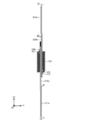
- FIG. 1A is a perspective view showing a probe pin according to the first embodiment.
- FIG. 1B is a partial cross-sectional view illustrating the probe pin according to the first embodiment.
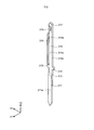
- FIG. 2A is a perspective view showing the lower plunger.
- FIG. 2B is a diagram illustrating the lower plunger.
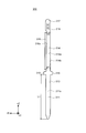
- FIG. 3A is a perspective view showing the upper plunger.
- FIG. 3B is a diagram showing the upper plunger.
- FIG. 4A is a diagram showing a probe pin and a socket.
- FIG. 4B is a diagram showing a probe pin and a socket.
- FIG. 4C is a diagram showing a probe pin and a socket.
- FIG. 5A is a schematic diagram illustrating a positional relationship between an upper plunger, a lower plunger, and a coil spring.
- FIG. 5B is a schematic diagram illustrating a positional relationship between an upper plunger, a lower plunger, and a coil spring.
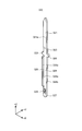
- FIG. 6A is a perspective view showing a probe pin according to the second embodiment.
- FIG. 6B is a partial cross-sectional view illustrating a probe pin according to the second embodiment.
- FIGS. 1A to 6B illustrate a three-dimensional orthogonal coordinate system including an X axis, a Y axis, and a Z axis for convenience of description.
- the positive direction of the X axis is defined as a + X direction (right direction)
- the positive direction of the Y axis is defined as a + Y direction (forward direction)
- the positive direction of the Z axis is defined as a + Z direction (upward direction).
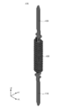
- FIG. 1A is a perspective view of the probe pin 300 according to the first embodiment.
- FIG. 1B is a partial cross-sectional view of the probe pin 300.
- the probe pin 300 includes a lower plunger 310 (an example of a “first plunger”), an upper plunger 320 (an example of a “second plunger”), and a coil spring 330 (an example of an “elastic body”), all of which are made of metal. I have.
- the lower plunger 310 is a rod-shaped member arranged on the lower end side of the probe pin 300.
- the lower plunger 310 is formed by punching, bending, and cutting and raising a metal plate member.
- the lower plunger 310 includes a contact portion 311 (an example of a “first contact portion”), a main body portion 314 (an example of a “first main body portion”), and a holding portion 317 (an example of a “first holding portion”). , Is provided.
- the contact portion 311 has a predetermined width in the left-right direction and extends in the up-down direction.
- the thickness direction of the contact portion 311 is the front-back direction.
- the contact portion 311 has a surface 311a on the + Y side. The width of the lower end side of the contact portion 311 in the left-right direction decreases toward the lower end. The lower end of the contact portion 311 contacts the inspection substrate 101 (described later).
- the main unit 314 is provided above the contact unit 311.
- the main body 314 has a predetermined width in the left-right direction and extends in the up-down direction.
- the thickness direction of the main body 314 is the front-back direction.
- the main body 314 has a surface 314a on the + Y side and a surface 314b on the -X side. Surface 314a is parallel to surface 311a.
- the contact part 311 and the main body part 314 are connected via a step part 313.
- the surface 314a is located on the ⁇ Y side of the surface 311a.
- a locking portion 315 extending in the left-right direction is provided on the lower end side of the main body portion 314 (above the step portion 313).
- the extending direction of the locking portion 315 may not be the left-right direction.
- the locking portion 315 may extend in the front-rear direction, may extend in the left-right direction, and may further extend in the front-rear direction.
- the locking portion 315 may not be provided on the lower end side of the main body portion 314.
- the locking portion 315 may be provided on the upper end side of the contact portion 311 (below the step portion 313).
- the length from the lower end of the locking portion 315 to the lower end of the contact portion 311 is L1.
- the locking portion 315 contacts a step portion 214 (described later) of the lower through hole 211.
- a wall 316 (an example of a “first wall”) that extends in the + Y direction from the + X end side of the main body 314 is provided above the locking section 315 of the main body 314.
- the wall portion 316 is formed by bending a portion on the + X side of the main body portion 314 in the + Y direction.
- the wall portion 316 has a predetermined width in the front-rear direction and extends in the up-down direction.
- the thickness direction of the wall portion 316 is the left-right direction.
- the wall portion 316 has a surface 316a on the ⁇ X side. Surface 316a is perpendicular to surface 314a.
- the surface 316a does not have to be perpendicular to the surface 314a. Further, the wall portion 316 may extend in the + Y direction, and may extend in another direction. Further, the wall 316 may extend from an intermediate portion of the main body 314 in the left-right direction.
- the width of the main body 314 in the left-right direction decreases from the lower side toward the upper side. That is, the width of the surface 314a in the left-right direction decreases from the lower side to the upper side. In other words, the distance from the surface 314b to the surface 316a decreases from the lower side to the upper side. As shown in FIG. 2B, if the width in the left-right direction on the lower end side of the surface 314a is w1 and the width in the left-right direction on the upper end side is w2, w1> w2.
- the holding section 317 is provided above the main body section 314.
- the holding portion 317 has a predetermined width in the left-right direction and extends in the up-down direction.
- the holding portion 317 has an engaging portion 318 (an example of a “first engaging portion”) that protrudes in the ⁇ Y direction.
- the engaging portion 318 is formed by cutting and raising the central region of the plane portion of the holding portion 317 in the ⁇ Y direction.
- An upper end 331 (described later) of the coil spring 330 is engaged with the engaging portion 318 (see FIG. 1B).
- the upper plunger 320 will be described with reference to FIGS. 1B, 3A, and 3B.
- the upper plunger 320 is a rod-shaped member arranged on the upper end side of the probe pin 300.
- the upper plunger 320 is formed by performing a punching process, a bending process, and a cut-and-raise process on a metal plate-shaped member.
- the upper plunger 320 includes a contact portion 321 (an example of a “second contact portion”), a main body portion 324 (an example of a “second main body portion”), a holding portion 327 (an example of a “second holding portion”), Is provided.
- the contact portion 321 has a predetermined width in the left-right direction and extends in the up-down direction.
- the thickness direction of the contact portion 321 is the front-back direction.
- the contact portion 321 has a surface 321a on the ⁇ Y side. The width of the upper end side of the contact portion 321 in the left-right direction decreases toward the upper end. The upper end of the contact portion 321 contacts the electric component 102 (described later).
- the main body 324 is provided below the contact portion 321.
- the main body 324 has a predetermined width in the left-right direction, and extends in the up-down direction.
- the thickness direction of the main body 324 is the front-back direction.
- the main body 324 has a surface 324a on the ⁇ Y side and a surface 324b on the + X side. Surface 324a is parallel to surface 321a.
- the contact part 321 and the main body part 324 are connected via a step part 323.
- the surface 324a is located on the + Y side of the surface 321a.
- the distance d2 between the surface 324a and the surface 321a is expressed by the following equation (2) using the thickness t2 of the upper plunger 320.
- t1 t2.
- the step portion 323 may not be provided.
- d2 t2 / 2 (2)
- a locking portion 325 extending in the left-right direction is provided on the upper end side of the main body portion 324 (below the step portion 323).
- the extending direction of the locking portion 325 may not be the left-right direction.
- the locking portion 325 may extend in the front-rear direction, may extend in the left-right direction, and may further extend in the front-rear direction.
- the locking portion 325 may not be provided on the upper end side of the main body 324.
- the locking portion 325 may be provided on a lower end side of the contact portion 321 (above the step portion 323).
- the length from the upper end of the locking portion 325 to the upper end of the contact portion 321 is L2.
- the locking portion 325 is in contact with a step portion 224 (described later) of the upper through hole 221.
- a wall portion 326 (an example of a “second wall portion”) extending in the ⁇ Y direction from the ⁇ X end side of the main body portion 324 is provided below the locking portion 325 of the main body portion 324.
- the wall portion 326 is formed by bending the ⁇ X side portion of the main body portion 324 in the ⁇ Y direction.
- the wall portion 326 has a predetermined width in the front-rear direction and extends in the up-down direction.
- the thickness direction of the wall portion 326 is the left-right direction.
- the wall 326 has a surface 326a on the + X side. Surface 326a is perpendicular to surface 324a.
- the surface 326a may not be perpendicular to the surface 324a.
- the wall portion 326 may extend in the ⁇ Y direction, and may further extend in another direction. Further, the wall 326 may extend from an intermediate portion of the main body 324 in the left-right direction.
- the width of the main body 324 in the left-right direction decreases from the upper side to the lower side. That is, the width of the surface 324a in the left-right direction decreases from the upper side to the lower side. In other words, the distance from the surface 324b to the surface 326a decreases from the upper side to the lower side. As shown in FIG. 3B, if the width in the left-right direction on the upper end side of the surface 324a is w3 and the width in the left-right direction on the lower end side is w4, w3> w4.
- the holding section 327 is provided below the main body section 324.
- the holding portion 327 has a predetermined width in the left-right direction, and extends in the up-down direction.
- the holding portion 327 is formed with an engaging portion 328 (an example of a “second engaging portion”) projecting in the + Y direction.
- the engaging portion 328 is formed by cutting and raising the central region of the plane portion of the holding portion 327 in the + Y direction.
- the lower end 333 (described later) of the coil spring 330 is engaged with the engaging portion 328 (see FIG. 1B).
- coil spring 330 (Coil spring 330) The coil spring 330 will be described with reference to FIG. 1B.
- the coil spring 330 has an upper end 331, an intermediate part 332, and a lower end 333.
- the coil spring 330 is a tension spring in which the intermediate portion 332 is elastically deformed when the upper end portion 331 and the lower end portion 333 are separated from each other, and an urging force is applied in a direction in which the upper end portion 331 and the lower end portion 333 approach.
- FIG. 1B shows a natural state of the coil spring 330.
- the upper end 331 engages with the engaging portion 318 provided on the holding portion 317 of the lower plunger 310 as described above.
- the lower end portion 333 engages with the engaging portion 328 provided on the holding portion 327 of the upper plunger 320 as described above.
- the intermediate portion 332 surrounds the main body 314 of the lower plunger 310 and the main body 324 of the upper plunger 320.
- the lower plunger 310 and the upper plunger 320 are arranged such that the surface 314a of the main body 314 of the lower plunger 310 and the surface 324a of the main body 324 of the upper plunger 320 face each other, as shown in FIG. 1B.
- t1 t2.
- the surface 311a is located on the + Y side by d1 from the surface 314a.
- the surface 321a is located on the ⁇ Y side by d2 from the surface 324a. Therefore, the position of the lower end of lower plunger 310 in the front-rear direction and the position of the upper end of upper plunger 320 in the front-rear direction can be matched.
- the lower plunger 310 and the upper plunger 320 are inserted into the coil spring 330 so that the main body 314 and the main body 324 are surrounded by the coil spring 330.
- the upper end 331 of the coil spring 330 is fitted into the engaging portion 318 of the lower plunger 310.
- the lower end 333 of the coil spring 330 is fitted into the engaging portion 328 of the upper plunger 320.
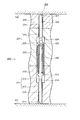
- Such a probe pin 300 is supported by a support of the socket 200 as shown in FIGS. 4A to 4C.
- the support of the socket 200 is constituted by a lower housing 210 and an upper housing 220.
- a lower through hole 211 is formed in the lower housing 210.
- the lower through-hole 211 includes a lower small-diameter portion 212 and an upper large-diameter portion 213.
- the inner diameter of the small diameter portion 212 is larger than the width of the contact portion 311 of the lower plunger 310 in the left-right direction, and smaller than the width of the locking portion 315 in the left-right direction.
- the vertical length L3 of the small diameter portion 212 is shorter than the above-described L1 (the length from the lower end of the locking portion 315 to the lower end of the contact portion 311 in the lower plunger 310).
- the inner diameter of the large diameter portion 213 is larger than the outer diameter of the coil spring 330.
- the small diameter portion 212 and the large diameter portion 213 form a step portion 214.
- the upper through hole 221 is formed in the upper housing 220.
- the upper through-hole 221 includes an upper small-diameter portion 222 and a lower large-diameter portion 223.
- the inner diameter of the small diameter portion 222 is larger than the width of the contact portion 321 of the upper plunger 320 in the left-right direction, and smaller than the width of the locking portion 325 in the left-right direction.
- the vertical length L4 of the small-diameter portion 222 is shorter than the above-described L2 (the length from the upper end of the locking portion 325 to the upper end of the contact portion 321 in the upper plunger 320).
- the inner diameter of the large diameter portion 223 is larger than the outer diameter of the coil spring 330.
- the small-diameter portion 222 and the large-diameter portion 223 form a step portion 224.
- the inside diameter of the small diameter part 222 is equal to the inside diameter of the small diameter part 212.
- the inner diameter of the large diameter part 223 is equal to the inner diameter of the large diameter part 213.
- the lower housing 210 and the upper housing 220 are connected to each other so that the lower through hole 211 and the upper through hole 221 are continuous with each other to form a support for the socket 200.
- the probe pin 300 is disposed in a through hole formed by connecting the lower through hole 211 and the upper through hole 221.
- the floating 230 is disposed above the upper housing 220.
- the floating 230 has a through hole 231 formed therein.
- the inner diameter of the through hole 231 is larger than the width of the contact portion 321 of the upper plunger 320 in the left-right direction.
- FIG. 4A is a partial sectional view of the probe pin 300 and the socket 200 in a non-use state. As shown in FIG. 4A, the socket 200 is not placed on the inspection substrate 101, and a gap exists between the lower end of the contact portion 311 of the lower plunger 310 and the upper surface of the inspection substrate 101. are doing.
- the upper housing 220 and the floating 230 are urged by an elastic body (not shown) so as to be vertically separated from each other, and there is a gap between the upper surface of the upper housing 220 and the lower surface of the floating 230. are doing.
- the lower end of the locking portion 315 of the lower plunger 310 is in contact with the step portion 214 of the lower through hole 211 of the lower housing 210 in the state shown in FIG. 4A. This prevents the lower plunger 310 from falling down. As described above, L1> L3. Therefore, in this state, the contact portion 311 of the lower plunger 310 protrudes below the lower surface of the lower housing 210.
- the upper end of the locking portion 325 of the upper plunger 320 is located below the step portion 224 of the upper through hole 221 of the upper housing 220. That is, the upper end of the locking portion 325 is not in contact with the step portion 224 and is located in the large-diameter portion 223.
- the lower plunger 310 and the upper plunger 320 are connected via the coil spring 330.
- the coil spring 330 is not elastically deformed.
- the contact portion 321 of the upper plunger 320 protrudes upward from the upper surface of the upper housing 220.
- the contact portion 321 does not protrude upward from the upper surface of the floating 230.
- FIG. 4B is a partial cross-sectional view in a state where the socket 200 is placed on the inspection substrate 101.
- the contact portion 311 of the lower plunger 310 is in contact with the inspection substrate 101.
- the lower plunger 310 is pressed upward and moves.
- the lower end of the locking part 315 is separated from the step part 214.
- the upper plunger 320 connected to the lower plunger 310 via the coil spring 330 also moves upward.
- the upward movement of the upper plunger 320 is prevented by the upper end of the locking portion 325 abutting on the step portion 224 of the upper housing 220.
- the contact portion 311 of the lower plunger 310 and the contact portion 321 of the upper plunger 320 relatively approach each other, and the coil spring 330 is elastically deformed.
- FIG. 4C is a partial cross-sectional view of the probe pin 300 and the socket 200 in use.
- the electric component 102 is placed on the floating 230 and pressed further downward, the lower surface of the floating 230 comes into contact with the upper surface of the upper housing 220.
- the upper plunger 320 is also pressed downward by the electric component 102 and moves.
- the upper end of the locking portion 325 is separated from the step portion 224.
- the contact portion 311 of the lower plunger 310 and the contact portion 321 of the upper plunger 320 relatively approach each other, and the coil spring 330 is further elastically deformed.
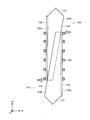
- FIGS. 5A and 5B are diagrams schematically showing a relationship among the lower plunger 310, the upper plunger 320, and the coil spring 330 in the state of FIGS. 4A and 4C.
- the lower plunger 310 has the contact portion 311, the main body 314, and the wall 316 extending in the + Y direction from the + X end side of the main body 314.
- the width of the main body 314 in the left-right direction decreases from the lower side to the upper side.
- the upper plunger 320 has a contact portion 321, a main body 324, and a wall 326 extending in the ⁇ Y direction from the ⁇ X end side of the main body 324.
- the width of the main body 324 in the left-right direction decreases from the upper side to the lower side.
- the contact portion 311 and the contact portion 321 approach relatively.
- the contact position between the upper end of the wall 316 and the surface 324b is T1.
- the contact position between the lower end of the wall 326 and the surface 314b is T2.
- d11 is the width of the main body 314 in the left-right direction at the position of T1.
- d12 is the vertical distance between T1 and T2.
- w5 t1 + t2 + d11 + d12 ⁇ tan ⁇ 1 (5)
- t1, t2 and d11 are constants.
- d12 is a variable that depends on the positional relationship between the contact part 311 and the contact part 321. As is clear from equation (5), the distance w5 increases as d12 increases. That is, the distance w5 increases as the contact part 311 and the contact part 321 come closer.
- FIG. 5A shows a non-use state of the probe pin 300 and the socket 200.
- the coil spring 330 is not elastically deformed. In this state, a gap exists in the left-right direction between the inner diameter of the coil spring 330 and the lower plunger 310 and the upper plunger 320. Therefore, no force acts to press the surface 324b toward the surface 316a. Similarly, no force acts on surface 314b toward surface 326a.
- FIG. 5B shows a usage state of the probe pin 300 and the socket 200.
- the lower plunger 310 and the upper plunger 320 exert a force that presses the surface 314b toward the surface 326a and a force that presses the surface 324b toward the surface 316a (as indicated by an arrow in FIG. 5B). .) Acts.
- the current flowing through the probe pin 300 passes from the contact portion 311 of the lower plunger 310 to a contact position T1 between the main body 324 and the wall 316 or a contact position T2 between the main body 314 and the wall 326, and the upper plunger. 320 to the contact portion 321. Therefore, the conductivity between the lower plunger 310 and the upper plunger 320 can be improved.
- the surface 314b faces the surface 326a.
- a pressing force or a force pressing the surface 324b toward the surface 316a acts.
- the coil spring 330 is a tension spring, when the contact portion 311 and the contact portion 321 relatively approach each other, the inner diameter of the intermediate portion 332 is reduced. Therefore, the force pressing the surface 314b toward the surface 326a and the force pressing the surface 324b toward the surface 316a act more strongly, and the contact properties are further stabilized.
- the first contact portion provided at the lower end, the first body portion provided above the first contact portion, and the front-back direction from the first body portion
- a first plunger having a first wall portion extending to one side, a second contact portion provided at an upper end, and a second main body portion provided below the second contact portion.
- the force that presses the main body 324 toward the wall 316 and the force that presses the main body 314 toward the wall 326 does not act when the probe pin 300 and the socket 200 are not used.
- the present invention is not limited to this.
- a force for pressing the main body 324 toward the wall 316 and pressing the main body 314 toward the wall 326 are used. Force can be applied.
- the lower plunger 310 and the upper plunger 320 may be connected by an elastic body such as a metal spring other than the coil spring, or may be connected by a non-metallic elastic body. Further, the lower plunger 310 and the upper plunger 320 need not be connected by an elastic body.
- the wall 316 is pressed by the main body 324 and the wall 326 is pressed by the main body 314 has been described, but the present invention is not limited to this.
- the wall portion 326 may not be provided on the upper plunger 320, and only the wall portion 316 may be pressed by the main body portion 324.
- the wall portion 316 may not be provided on the lower plunger 310, and only the wall portion 326 may be pressed by the main body portion 314.
- the elastic body that connects the lower plunger 310 and the upper plunger 320 is described using a tension spring as an example.
- a compression spring can also be used as the elastic body.
- a second embodiment of the probe pin using a compression spring as the elastic body will be described.
- FIG. 6A is a perspective view of a probe pin 400 according to the second embodiment.
- FIG. 6B is a partial cross-sectional view of the probe pin 400.
- the probe pin 400 includes a lower plunger 410, an upper plunger 420, and a coil spring 430, all of which are made of metal.
- the lower plunger 410 is a component corresponding to the lower plunger 310 of the first embodiment, and has a configuration common to the lower plunger 310. The description of the common configuration is omitted.
- the lower plunger 410 has an engaging portion 418 projecting in the ⁇ Y direction on the lower end side of the main body portion 414 and above the step portion 413.
- the upper plunger 420 is a component corresponding to the upper plunger 320 of the first embodiment, and has a configuration common to the upper plunger 320. The description of the common configuration is omitted.
- the upper plunger 420 has an engaging portion 428 protruding in the + Y direction below the step 423 on the upper end side of the main body 424.
- the coil spring 430 is a component corresponding to the coil spring 330 of the first embodiment, and has a configuration common to the coil spring 330. The description of the common configuration is omitted.
- the coil spring 430 is a compression spring in which the intermediate portion 432 is elastically deformed when the upper end portion 431 and the lower end portion 433 approach each other, and an urging force is applied in a direction in which the upper end portion 431 and the lower end portion 433 are separated.
- the upper end 431 of the coil spring 430 engages with the engaging portion 428 of the upper plunger 420.
- the lower end 433 of the coil spring 430 engages with the engaging portion 418 of the lower plunger 410.
- the lower plunger 410, the upper plunger 420, and the coil spring 430 constituting the probe pin 400 have been described. Even when such a probe pin 400 is used, similarly to the case of using the probe pin 300 according to the first embodiment, the wall 416 is pressed by the main body 424 and the wall 426 is pressed by the main body 414. can do.
- the present disclosure is widely applicable to probe pins for electrically connecting a member to be inspected and a wiring board.
Landscapes
- Physics & Mathematics (AREA)
- General Physics & Mathematics (AREA)
- Measuring Leads Or Probes (AREA)
Abstract
良好な導通性を得ることができるプローブピンを提供する。プローブピンは、下端に設けられた第1接触部、前記第1接触部よりも上側に設けられた第1本体部、および、前記第1本体部から前後方向の一方に延出した第1壁部、を有する第1プランジャと、上端に設けられた第2接触部、および、前記第2接触部よりも下側に設けられた第2本体部、を有する第2プランジャと、を備え、前記第2本体部は、前記第1壁部を押圧する。
Description
本開示は、ICパッケージ等の性能試験等に使用されるプローブピン及びソケットに関する。
例えば特許文献1に記載されているように、従来、ICパッケージ等の電気部品を検査する際、ソケットが用いられている。このソケットは、電気部品と検査装置側の基板である検査用基板とを電気的に接続する複数のプローブピンを備えている。
これらのプローブピンは、電気部品の端子に接触する第1可動部材と、検査用基板の端子に接触する第2可動部材と、第1可動部材と第2可動部材の間に配置され、第1可動部材と第2可動部材とが互いに離れるように反発するコイルバネとを有する。
このようなプローブピンには、良好な導通性が求められる。
本開示の目的は、良好な導通性を得ることができるプローブピンを提供することである。
本開示の一態様に係るプローブピンは、下端に設けられた第1接触部、前記第1接触部よりも上側に設けられた第1本体部、および、前記第1本体部から前後方向の一方に延出した第1壁部、を有する第1プランジャと、上端に設けられた第2接触部、および、前記第2接触部よりも下側に設けられた第2本体部、を有する第2プランジャと、を備え、前記第2本体部は、前記第1壁部を押圧する、プローブピンである。
本開示によれば、良好な導通性を得ることができる。
以下、本開示の実施形態について、図面を参照して詳細に説明する。なお、以下に説明する実施形態は一例であり、本開示はこの実施形態により限定されるものではない。以下で説明する実施形態の構成要素は適宜組み合わせることができる。また、一部の構成要素を用いない場合もある。
図1A~図6Bには、説明の便宜上、X軸、Y軸およびZ軸からなる3次元直交座標系が描かれている。X軸の正方向を+X方向(右方向)、Y軸の正方向を+Y方向(前方向)、Z軸の正方向を+Z方向(上方向)とそれぞれ定義する。
(第1実施形態)
図1Aは、第1実施形態に係るプローブピン300の斜視図である。図1Bは、プローブピン300の部分断面図である。プローブピン300は、いずれも金属製の下側プランジャ310(「第1プランジャ」の一例)、上側プランジャ320(「第2プランジャ」の一例)およびコイルバネ330(「弾性体」の一例)を備えている。
図1Aは、第1実施形態に係るプローブピン300の斜視図である。図1Bは、プローブピン300の部分断面図である。プローブピン300は、いずれも金属製の下側プランジャ310(「第1プランジャ」の一例)、上側プランジャ320(「第2プランジャ」の一例)およびコイルバネ330(「弾性体」の一例)を備えている。
(下側プランジャ310)
図1B、図2Aおよび図2Bを参照して、下側プランジャ310について説明する。
図1B、図2Aおよび図2Bを参照して、下側プランジャ310について説明する。
下側プランジャ310は、プローブピン300の下端側に配置される棒状部材である。下側プランジャ310は、金属製の板状部材に対して打ち抜き加工、曲げ加工および切り起こし加工が施されることで形成される。
下側プランジャ310は、接触部311(「第1接触部」の一例)と、本体部314(「第1本体部」の一例)と、保持部317(「第1保持部」の一例)と、を備える。
接触部311は、左右方向に所定の幅を有し、上下方向に延在している。接触部311の板厚方向は、前後方向である。接触部311は、+Y側の面311aを有する。接触部311の下端側は、下端に向けて左右方向の幅が狭くなっている。接触部311の下端は、検査用基板101(後述する。)と接触する。
本体部314は、接触部311の上側に設けられている。本体部314は、左右方向に所定の幅を有し、上下方向に延在している。本体部314の板厚方向は、前後方向である。本体部314は、+Y側の面314aと、-X側の面314bとを有する。面314aは、面311aと平行である。
接触部311と、本体部314とは、段差部313を介して接続されている。面314aは、面311aよりも-Y側に位置している。面314aと、面311aとの距離d1は、下側プランジャ310の板厚t1を用いて、以下の式(1)で表される。なお、段差部313は設けられていなくともよい。
d1=t1/2 …(1)
d1=t1/2 …(1)
本体部314の下端側(段差部313の上側)には、左右方向に延出する係止部315が設けられている。係止部315の延出方向は、左右方向でなくてもよい。例えば、係止部315は、前後方向に延出していてもよいし、左右方向に延出し、さらに前後方向に延出していてもよい。
また、係止部315は、本体部314の下端側に設けられていなくてもよい。例えば、係止部315は、接触部311の上端側(段差部313の下側)に設けられていてもよい。係止部315の下端から接触部311の下端までの長さは、L1である。係止部315は、下側貫通孔211の段差部214(後述する。)と当接する。
本体部314における係止部315の上側には、本体部314の+X端側から+Y方向に延出する壁部316(「第1壁部」の一例)が設けられている。壁部316は、本体部314の+X側の部分を+Y方向に折り曲げることで形成されている。
壁部316は、前後方向に所定の幅を有し、上下方向に延在している。壁部316の板厚方向は、左右方向である。壁部316は、-X側の面316aを有する。面316aは、面314aと垂直である。
なお、面316aは、面314aと垂直でなくてもよい。また、壁部316は、+Y方向に延出し、さらに他の方向に延出していてもよい。さらに、壁部316は、本体部314の左右方向における中間部から延出していてもよい。
本体部314の左右方向の幅は、下側から上側に向かうにつれて狭くなっている。すなわち、面314aの左右方向の幅は、下側から上側に向かうにつれて狭くなっている。換言すると、面314bから面316aまでの距離は、下側から上側に向かうにつれて短くなっている。図2Bに示すように、面314aの下端側における左右方向の幅をw1、上端側における左右方向の幅をw2とすると、w1>w2である。
保持部317は、本体部314の上側に設けられている。保持部317は、左右方向に所定の幅を有し、上下方向に延在している。
保持部317には、-Y方向に突出する係合部318(「第1係合部」の一例)が形成されている。係合部318は、保持部317の平面部の中央領域が-Y方向に切り起こされることで形成されている。係合部318には、コイルバネ330の上端部331(後述する。)が係合する(図1Bを参照)。
(上側プランジャ320)
図1B、図3Aおよび図3Bを参照して、上側プランジャ320について説明する。
図1B、図3Aおよび図3Bを参照して、上側プランジャ320について説明する。
上側プランジャ320は、プローブピン300の上端側に配置される棒状部材である。上側プランジャ320は、金属製の板状部材に対して打ち抜き加工、曲げ加工および切り起こし加工が施されることで形成される。
上側プランジャ320は、接触部321(「第2接触部」の一例)と、本体部324(「第2本体部」の一例)と、保持部327(「第2保持部」の一例)と、を備える。
接触部321は、左右方向に所定の幅を有し、上下方向に延在している。接触部321の板厚方向は、前後方向である。接触部321は、-Y側の面321aを有する。接触部321の上端側は、上端に向けて左右方向の幅が狭くなっている。接触部321の上端は、電気部品102(後述する。)と接触する。
本体部324は、接触部321の下側に設けられている。本体部324は、左右方向に所定の幅を有し、上下方向に延在している。本体部324の板厚方向は、前後方向である。本体部324は、-Y側の面324aと、+X側の面324bとを有する。面324aは、面321aと平行である。
接触部321と、本体部324とは、段差部323を介して接続されている。面324aは、面321aよりも+Y側に位置している。面324aと、面321aとの距離d2は、上側プランジャ320の板厚t2を用いて、以下の式(2)で表される。なお、本実施形態では、t1=t2である。段差部323は設けられていなくともよい。
d2=t2/2 …(2)
d2=t2/2 …(2)
本体部324の上端側(段差部323の下側)には、左右方向に延出する係止部325が設けられている。係止部325の延出方向は、左右方向でなくてもよい。例えば、係止部325は、前後方向に延出していてもよいし、左右方向に延出し、さらに前後方向に延出していてもよい。
また、係止部325は、本体部324の上端側に設けられていなくてもよい。例えば、係止部325は、接触部321の下端側(段差部323の上側)に設けられていてもよい。係止部325の上端から接触部321の上端までの長さは、L2である。係止部325は、上側貫通孔221の段差部224(後述する。)と当接する。
本体部324における係止部325の下側には、本体部324の-X端側から-Y方向に延出する壁部326(「第2壁部」の一例)が設けられている。壁部326は、本体部324の-X側の部分を-Y方向に折り曲げることで形成されている。
壁部326は、前後方向に所定の幅を有し、上下方向に延在している。壁部326の板厚方向は、左右方向である。壁部326は、+X側の面326aを有する。面326aは、面324aと垂直である。
なお、面326aは、面324aと垂直でなくてもよい。また、壁部326は、-Y方向に延出し、さらに他の方向に延出していてもよい。さらに、壁部326は、本体部324の左右方向における中間部から延出していてもよい。
本体部324の左右方向の幅は、上側から下側に向かうにつれて狭くなっている。すなわち、面324aの左右方向の幅は、上側から下側に向かうにつれて狭くなっている。換言すると、面324bから面326aまでの距離は、上側から下側に向かうにつれて短くなっている。図3Bに示すように、面324aの上端側における左右方向の幅をw3、下端側における左右方向の幅をw4とすると、w3>w4である。
保持部327は、本体部324の下側に設けられている。保持部327は、左右方向に所定の幅を有し、上下方向に延在している。
保持部327には、+Y方向に突出する係合部328(「第2係合部」の一例)が形成されている。係合部328は、保持部327の平面部の中央領域が+Y方向に切り起こされることで形成されている。係合部328には、コイルバネ330の下端部333(後述する。)が係合する(図1Bを参照)。
(コイルバネ330)
図1Bを参照して、コイルバネ330について説明する。
図1Bを参照して、コイルバネ330について説明する。
コイルバネ330は、上端部331と、中間部332と、下端部333とを有する。コイルバネ330は、上端部331と下端部333とが互いに離れることで中間部332が弾性変形し、上端部331と下端部333とが近付く方向に付勢力が付与される引張バネである。図1Bは、コイルバネ330の自然状態を示している。
上端部331は、上述のとおり、下側プランジャ310の保持部317に設けられた係合部318に係合する。下端部333は、上述のとおり、上側プランジャ320の保持部327に設けられた係合部328に係合する。
中間部332は、下側プランジャ310の本体部314および上側プランジャ320の本体部324を取り囲む。
以上、プローブピン300を構成する下側プランジャ310、上側プランジャ320およびコイルバネ330について説明した。
下側プランジャ310および上側プランジャ320は、図1Bに示すように、下側プランジャ310の本体部314の面314aと上側プランジャ320の本体部324の面324aとが対向するように配置される。
上述したように、t1=t2である。また、面311aは、面314aよりもd1だけ+Y側に位置している。また、面321aは、面324aよりもd2だけ-Y側に位置している。よって、下側プランジャ310の下端の前後方向における位置と、上側プランジャ320の上端の前後方向における位置とを一致させることができる。
コイルバネ330によって本体部314および本体部324が取り囲まれるように、下側プランジャ310および上側プランジャ320はコイルバネ330に挿通される。コイルバネ330の上端部331は、下側プランジャ310の係合部318に嵌め込まれる。コイルバネ330の下端部333は、上側プランジャ320の係合部328に嵌め込まれる。
このようなプローブピン300は、図4A~図4Cに示すように、ソケット200の支持体によって支持される。ソケット200の支持体は、下側ハウジング210と、上側ハウジング220とによって構成される。
下側ハウジング210には、下側貫通孔211が形成されている。下側貫通孔211は、下側の小径部212と、上側の大径部213とから構成されている。小径部212の内径は、下側プランジャ310の接触部311の左右方向の幅よりも大きく、係止部315の左右方向の幅よりも小さい。
小径部212の上下方向の長さL3は、上述のL1(下側プランジャ310における係止部315の下端から接触部311の下端までの長さ)よりも短い。大径部213の内径は、コイルバネ330の外径よりも大きい。小径部212と大径部213とにより、段差部214が形成される。
上側ハウジング220には、上側貫通孔221が形成されている。上側貫通孔221は、上側の小径部222と、下側の大径部223とから構成されている。小径部222の内径は、上側プランジャ320の接触部321の左右方向の幅よりも大きく、係止部325の左右方向の幅よりも小さい。
小径部222の上下方向の長さL4は、上述のL2(上側プランジャ320における係止部325の上端から接触部321の上端までの長さ)よりも短い。大径部223の内径は、コイルバネ330の外径よりも大きい。小径部222と大径部223とにより、段差部224が形成される。小径部222の内径は、小径部212の内径と等しい。大径部223の内径は、大径部213の内径と等しい。
下側貫通孔211と上側貫通孔221とが連続するように、下側ハウジング210と上側ハウジング220とは互いに連結され、ソケット200の支持体を構成している。プローブピン300は、下側貫通孔211と上側貫通孔221とが連結されて構成される貫通孔内に配置される。
上側ハウジング220の上側に、フローティング230が配置される。フローティング230には、貫通孔231が形成されている。貫通孔231の内径は、上側プランジャ320の接触部321の左右方向の幅よりも大きい。
以上、ソケット200を構成する下側ハウジング210、上側ハウジング220およびフローティング230について説明した。
図4Aは、プローブピン300およびソケット200の非使用状態における部分断面図を示している。図4Aに示すように、ソケット200は検査用基板101上に載置されておらず、下側プランジャ310の接触部311の下端と、検査用基板101の上面との間には、隙間が存在している。
また、上側ハウジング220とフローティング230とは、不図示の弾性体により互いに上下方向に離間するように付勢されており、上側ハウジング220の上面とフローティング230の下面との間には、隙間が存在している。
図4Aに示す状態では、下側プランジャ310の係止部315の下端が、下側ハウジング210の下側貫通孔211の段差部214に当接している。これにより、下側プランジャ310が下方向に抜け落ちることが防止される。また、上述のとおり、L1>L3である。そのため、この状態では、下側プランジャ310の接触部311は、下側ハウジング210の下面よりも下側に飛び出している。
このとき、上側プランジャ320の係止部325の上端は、上側ハウジング220の上側貫通孔221の段差部224より下側に位置している。すなわち、係止部325の上端は、段差部224と当接しておらず、大径部223内に位置している。
この状態における係止部325の上端と段差部224との距離は、L5である。L1、L3およびL5の間には、以下の式(3)に示される関係が存在する。
L1-L3>L5 …(3)
L1-L3>L5 …(3)
上述のとおり、下側プランジャ310と上側プランジャ320とは、コイルバネ330を介して連結されている。コイルバネ330は、弾性変形していない。上側プランジャ320の接触部321は、上側ハウジング220の上面から上側に突出している。接触部321は、フローティング230の上面から上側には突出していない。
図4Bは、ソケット200が検査用基板101上に載置された状態における部分断面図を示している。下側プランジャ310の接触部311は検査用基板101と接触している。検査用基板101と接触することで、下側プランジャ310は、上方向へ押圧されて移動する。係止部315の下端は、段差部214から離間する。
このとき、下側プランジャ310とコイルバネ330を介して連結された上側プランジャ320も上方向へ移動する。上述の式(3)の関係により、上側プランジャ320の上方向への移動は、係止部325の上端が上側ハウジング220の段差部224に当接することで阻止される。
そのため、下側プランジャ310の接触部311と上側プランジャ320の接触部321とが相対的に近付き、コイルバネ330が弾性変形する。
図4Cは、プローブピン300およびソケット200の使用状態における部分断面図を示している。電気部品102がフローティング230に載置されてさらに下方向に押圧されることで、フローティング230の下面が上側ハウジング220の上面と当接した状態となる。
このとき、上側プランジャ320も電気部品102によって下方向に押圧されて移動する。これにより、係止部325の上端は、段差部224から離間する。下側プランジャ310の接触部311と上側プランジャ320の接触部321とが相対的にさらに近付き、コイルバネ330がさらに弾性変形する。
図5Aおよび図5Bは、図4Aおよび図4Cの状態における下側プランジャ310、上側プランジャ320およびコイルバネ330の関係を模式的に示した図である。
上述のとおり、下側プランジャ310は、接触部311と、本体部314と、本体部314の+X端側から+Y方向に延出した壁部316とを有する。また、本体部314の左右方向の幅は、下側から上側に向かうにつれて狭くなっている。
上側プランジャ320は、接触部321と、本体部324と、本体部324の-X端側から-Y方向に延出した壁部326とを有する。また、本体部324の左右方向の幅は、上側から下側に向かうにつれて狭くなっている。
以下の説明では、理解を容易にするため、面316aと面314bとのなす角θ1と、面326aと面324bとのなす角θ2との間に、以下の式(4)の関係が成立するものを例に挙げる。
θ1=θ2 …(4)
θ1=θ2 …(4)
壁部316の上端が面324bと当接し、かつ、壁部326の下端が面314bと当接した状態で、接触部311と接触部321とが相対的に近付く。壁部316の上端と面324bとの接触位置は、T1である。壁部326の下端と面314bとの接触位置は、T2である。
壁部316の上端が面324bと当接し、かつ、壁部326の下端が面314bと当接した状態で、接触部311と接触部321とが相対的に近付く場合、面316aと面326aとは、平行を保つ。
このとき、壁部316の+X端と、壁部326の-X端との距離w5は、以下の式(5)で表される。d11はT1の位置における本体部314の左右方向の幅である。d12はT1とT2との上下方向の距離である。
w5=t1+t2+d11+d12・tanθ1 …(5)
w5=t1+t2+d11+d12・tanθ1 …(5)
式(5)中、t1、t2およびd11は定数である。また、d12は接触部311と接触部321との位置関係に依存する変数である。式(5)から明らかなように、d12が増大するほど、距離w5は増大する。すなわち、接触部311と接触部321とが近付くほど、距離w5は増大する。
図5Aは、プローブピン300およびソケット200の非使用状態を示している。コイルバネ330は弾性変形していない。この状態では、コイルバネ330の内径と、下側プランジャ310および上側プランジャ320との間には、左右方向に隙間が存在する。そのため、面324bを面316aに向けて押圧する力は作用しない。同様に、面314bを面326aに向けて押圧する力は作用しない。
図5Bは、プローブピン300およびソケット200の使用状態を示している。接触部311と接触部321とが相対的に近付くことで、壁部316の+X端および壁部326の-X端がコイルバネ330の内径面に当接し、コイルバネ330を拡径方向に押圧する。
これにより、下側プランジャ310および上側プランジャ320には、上述の押圧力の反作用として、面314bを面326aに向けて押圧する力および面324bを面316aに向けて押圧する力(図5Bにおいて矢印で示す。)が作用する。
これにより、面314bと面326aとが密着し、かつ、面324bと面316aとが密着する。そのため、下側プランジャ310と上側プランジャ320との接触性が安定する。
プローブピン300を流れる電流は、下側プランジャ310の接触部311から、本体部324と壁部316との接触位置T1または本体部314と壁部326との接触位置T2を通過して、上側プランジャ320の接触部321に至る。そのため、下側プランジャ310と上側プランジャ320との導通性を向上させることができる。
なお、上述の例では、θ1=θ2であり、かつ、面316aと面326aとが平行を保った状態で接触部311と接触部321とが相対的に近付くものを例に説明を行ったが、これらの条件を満たすことは必須ではない。
接触部311と接触部312とが相対的に近付くことで、下側プランジャ310および上側プランジャ320がコイルバネ330の内径面を拡径方向に押圧する構成であれば、面314bを面326aに向けて押圧する力または面324bを面316aに向けて押圧する力が作用する。
さらに、コイルバネ330を引張バネとしたことで、接触部311と接触部321とが相対的に近付くと中間部332の内径が縮径する。そのため、面314bを面326aに向けて押圧する力および面324bを面316aに向けて押圧する力がより強く作用し、接触性がさらに安定する。
以上説明したように、本実施形態によれば、下端に設けられた第1接触部、前記第1接触部よりも上側に設けられた第1本体部、および、前記第1本体部から前後方向の一方に延出した第1壁部、を有する第1プランジャと、上端に設けられた第2接触部、および、前記第2接触部よりも下側に設けられた第2本体部、を有する第2プランジャと、を備え、前記第2本体部は、前記第1壁部を押圧する、プローブピンが提供される。
そのため、良好な導通性を確保することができる。
なお、上述の実施形態では、プローブピン300およびソケット200の非使用状態で本体部324を壁部316に向けて押圧する力および本体部314を壁部326に向けて押圧する力が作用しないものを例に説明を行ったが、これに限定されない。
プローブピン300およびソケット200の非使用状態、または、ソケット200を検査用基板101に載置した状態で、コイルバネ330の内径と、下側プランジャ310および上側プランジャ320との間に隙間が無いようにして、本体部324を壁部316に向けて押圧する力および本体部314を壁部326に向けて押圧する力が作用するようにしてもよい。
このようにすれば、プローブピン300およびソケット200の非使用状態、または、ソケット200を検査用基板101に載置した状態で、下側プランジャ310、上側プランジャ320およびコイルバネ330の位置関係を安定させることができる。
また、上述の実施形態では、コイルバネ330により本体部314および本体部324を取り囲むものを例に説明を行ったが、これに限定されない。
例えば、本体部314および本体部324でソケット200の貫通孔の内径を押圧するようにしても、本体部324を壁部316に向けて押圧する力および本体部314を壁部326に向けて押圧する力を作用させることができる。
また、上述の実施形態では、下側プランジャ310と上側プランジャ320とをコイルバネ330を介して連結するものを例に説明を行ったが、これに限定されない。
例えば、下側プランジャ310と上側プランジャ320とをコイルバネ以外の金属ばね等の弾性体で連結するようにしてもよいし、非金属の弾性体で連結するようにしてもよい。さらに、下側プランジャ310と上側プランジャ320とを弾性体で連結しなくてもよい。
また、上述の実施形態では、本体部324で壁部316を押圧し、本体部314で壁部326を押圧するものを例に説明を行ったが、これに限定されない。例えば、上側プランジャ320に壁部326を設けず、本体部324で壁部316を押圧するのみとしてもよい。また、例えば、下側プランジャ310に壁部316を設けず、本体部314で壁部326を押圧するのみとしてもよい。
また、上述の実施形態では、下側プランジャ310と上側プランジャ320とを連結する弾性体として、引張バネを用いるものを例に説明を行ったが、これに限定されない。弾性体として、圧縮バネを用いることもできる。以下、弾性体として圧縮バネを用いたプローブピンの第二実施形態について説明する。
図6Aは、第二実施形態に係るプローブピン400の斜視図である。図6Bは、プローブピン400の部分断面図である。プローブピン400は、いずれも金属製の下側プランジャ410、上側プランジャ420およびコイルバネ430を備えている。
下側プランジャ410は、第一実施形態の下側プランジャ310に相当する部品であり、下側プランジャ310と共通する構成を有している。共通する構成については説明を省略する。
下側プランジャ410は、本体部414の下端側であって、段差部413の上側に、-Y方向に突出する係合部418を有している。
上側プランジャ420は、第一実施形態の上側プランジャ320に相当する部品であり、上側プランジャ320と共通する構成を有している。共通する構成については説明を省略する。
上側プランジャ420は、本体部424の上端側であって、段差部423の下側に、+Y方向に突出する係合部428を有している。
コイルバネ430は、第一実施形態のコイルバネ330に相当する部品であり、コイルバネ330と共通する構成を有している。共通する構成については説明を省略する。
コイルバネ430は、上端部431と下端部433とが互いに近付くことで中間部432が弾性変形し、上端部431と下端部433とが離れる方向に付勢力が付与される圧縮バネである。
コイルバネ430の上端部431は、上側プランジャ420の係合部428に係合する。コイルバネ430の下端部433は、下側プランジャ410の係合部418に係合する。
以上、プローブピン400を構成する下側プランジャ410、上側プランジャ420およびコイルバネ430について説明した。このようなプローブピン400を用いても、第一実施形態に係るプローブピン300を用いたのと同様に、本体部424で壁部416を押圧し、かつ、本体部414で壁部426を押圧することができる。
本出願は、2018年7月26日出願の特願2018-140273に基づく優先権を主張する。当該出願明細書および図面に記載された内容は、すべて本願明細書に援用される。
本開示は、被検査部材と配線基板とを電気的に接続するためのプローブピンに広く利用可能である。
101 検査用基板
102 電気部品
200 ソケット
210 下側ハウジング
211 下側貫通孔
212 小径部
213 大径部
214 段差部
220 上側ハウジング
221 上側貫通孔
222 小径部
223 大径部
224 段差部
230 フローティング
231 貫通孔
300 プローブピン
310 下側プランジャ
311 接触部
311a 面
313 段差部
314 本体部
314a、314b 面
315 係止部
316 壁部
316a 面
317 保持部
318 係合部
320 上側プランジャ
321 接触部
321a 面
323 段差部
324 本体部
324a、324b 面
325 係止部
326 壁部
326a 面
327 保持部
328 係合部
330 コイルバネ
331 上端部
332 中間部
333 下端部
400 プローブピン
410 下側プランジャ
420 上側プランジャ
430 コイルバネ
413 段差部
414 本体部
416 壁部
418 係合部
423 段差部
424 本体部
426 壁部
428 係合部
431 上端部
432 中間部
433 下端部
102 電気部品
200 ソケット
210 下側ハウジング
211 下側貫通孔
212 小径部
213 大径部
214 段差部
220 上側ハウジング
221 上側貫通孔
222 小径部
223 大径部
224 段差部
230 フローティング
231 貫通孔
300 プローブピン
310 下側プランジャ
311 接触部
311a 面
313 段差部
314 本体部
314a、314b 面
315 係止部
316 壁部
316a 面
317 保持部
318 係合部
320 上側プランジャ
321 接触部
321a 面
323 段差部
324 本体部
324a、324b 面
325 係止部
326 壁部
326a 面
327 保持部
328 係合部
330 コイルバネ
331 上端部
332 中間部
333 下端部
400 プローブピン
410 下側プランジャ
420 上側プランジャ
430 コイルバネ
413 段差部
414 本体部
416 壁部
418 係合部
423 段差部
424 本体部
426 壁部
428 係合部
431 上端部
432 中間部
433 下端部
Claims (16)
- 下端に設けられた第1接触部、前記第1接触部よりも上側に設けられた第1本体部、および、前記第1本体部から前後方向の一方に延出した第1壁部、を有する第1プランジャと、
上端に設けられた第2接触部、および、前記第2接触部よりも下側に設けられた第2本体部、を有する第2プランジャと、を備え、
前記第2本体部は、前記第1壁部を押圧する、
プローブピン。 - 前記第2本体部の左右方向における一端が前記第1壁部を押圧し、
前記第1接触部と前記第2接触部とが相対的に近付いた状態における、前記第1壁部の上端から前記第2本体部の左右方向における他端までの第1距離は、
前記第1接触部と前記第2接触部とが相対的に近付いていない状態における、前記第1距離よりも長い、
請求項1に記載のプローブピン。 - 前記第2本体部の左右方向の幅は、上側から下側に向かうにつれて細くなっている、
請求項1または2に記載のプローブピン。 - 前記第2プランジャは、前記第2本体部から前後方向の他方に延出した第2壁部をさらに有し、
前記第1本体部は、前記第2壁部を押圧する、
請求項1~3のいずれか一項に記載のプローブピン。 - 前記第2本体部は、前記第1壁部の上端を押圧し、
前記第1本体部は、前記第2壁部の下端を押圧する、
請求項4に記載のプローブピン。 - 前記第1接触部と前記第2接触部とが相対的に近付いた状態における、前記第1壁部の上端から前記第2壁部までの第2距離は、
前記第1接触部と前記第2接触部とが相対的に近付いていない状態における、前記第2距離よりも長い、
請求項4または5に記載のプローブピン。 - 前記第1本体部の左右方向の幅は、下側から上側に向かうにつれて細くなっている、
請求項4~6のいずれか一項に記載のプローブピン。 - 前記第1プランジャと前記第2プランジャとを連結し、前記第1接触部と前記第2接触部とが相対的に近付くと弾性変形する弾性体をさらに備える、
請求項1~7のいずれか一項に記載のプローブピン。 - 前記弾性体は、前記第1本体部および前記第2本体部を取り囲むコイルバネである、
請求項8に記載のプローブピン。 - 前記弾性体は、前記第1接触部と前記第2接触部とが相対的に近付くと伸びる引張バネである、
請求項8または9に記載のプローブピン。 - 前記弾性体は、前記第1接触部と前記第2接触部とが相対的に近付くと縮む圧縮バネである、
請求項8または9に記載のプローブピン。 - 前記第1プランジャは、前記弾性体の第一端を保持する第1保持部を有しており、
前記第2プランジャは、前記弾性体の第二端を保持する第2保持部を有している、
請求項8~11のいずれか一項に記載のプローブピン。 - 前記第1保持部は、前記前後方向の他方に突出し、かつ、前記第一端が係合する第1係合部を有しており、
前記第2保持部は、前記前後方向の一方に突出し、かつ、前記第二端が係合する第2係合部を有している、
請求項12に記載のプローブピン - 前記第1プランジャは、側方に延出する第1係止部を有しており、
前記第2プランジャは、側方に延出する第2係止部を有している、
請求項1~13のいずれか一項に記載のプローブピン。 - 前記第1プランジャは、前記第1接触部と前記第1本体部とを接続する第1段差部を有しており、
前記第2プランジャは、前記第2接触部と前記第2本体部とを接続する第2段差部を有しており、
前記第1接触部の前後方向の位置と前記第2接触部の前後方向の位置とは一致している、
請求項1~14のいずれか一項に記載のプローブピン。 - 請求項1~15のいずれか一項に記載のプローブピンと、
前記プローブピンを支持する支持体と、を備える、
ソケット。
Applications Claiming Priority (2)
| Application Number | Priority Date | Filing Date | Title |
|---|---|---|---|
| JP2018140273A JP2020017428A (ja) | 2018-07-26 | 2018-07-26 | プローブピンおよびソケット |
| JP2018-140273 | 2018-07-26 |
Publications (1)
| Publication Number | Publication Date |
|---|---|
| WO2020022236A1 true WO2020022236A1 (ja) | 2020-01-30 |
Family
ID=69180567
Family Applications (1)
| Application Number | Title | Priority Date | Filing Date |
|---|---|---|---|
| PCT/JP2019/028573 Ceased WO2020022236A1 (ja) | 2018-07-26 | 2019-07-22 | プローブピンおよびソケット |
Country Status (2)
| Country | Link |
|---|---|
| JP (1) | JP2020017428A (ja) |
| WO (1) | WO2020022236A1 (ja) |
Families Citing this family (2)
| Publication number | Priority date | Publication date | Assignee | Title |
|---|---|---|---|---|
| KR102304874B1 (ko) * | 2020-06-08 | 2021-09-24 | 주식회사 유니마이크로 | 반도체 검사용 프로브 핀 |
| JP2023104519A (ja) * | 2022-01-18 | 2023-07-28 | 株式会社日本マイクロニクス | プローブ |
Citations (6)
| Publication number | Priority date | Publication date | Assignee | Title |
|---|---|---|---|---|
| JPS62157576A (ja) * | 1985-12-20 | 1987-07-13 | オ−ガツト・インコ−ポレ−テツド | テストプロ−ブ |
| US5227718A (en) * | 1992-03-10 | 1993-07-13 | Virginia Panel Corporation | Double-headed spring contact probe assembly |
| US20080064236A1 (en) * | 2006-09-13 | 2008-03-13 | Hon Hai Precision Ind. Co., Ltd. | Electrical contact |
| WO2011013731A1 (ja) * | 2009-07-30 | 2011-02-03 | 株式会社ヨコオ | コンタクトプローブ及びソケット |
| WO2014136884A1 (ja) * | 2013-03-07 | 2014-09-12 | 株式会社サンケイエンジニアリング | コンタクトピン |
| WO2016021723A1 (ja) * | 2014-08-08 | 2016-02-11 | 日本発條株式会社 | 接続端子 |
-
2018
- 2018-07-26 JP JP2018140273A patent/JP2020017428A/ja active Pending
-
2019
- 2019-07-22 WO PCT/JP2019/028573 patent/WO2020022236A1/ja not_active Ceased
Patent Citations (6)
| Publication number | Priority date | Publication date | Assignee | Title |
|---|---|---|---|---|
| JPS62157576A (ja) * | 1985-12-20 | 1987-07-13 | オ−ガツト・インコ−ポレ−テツド | テストプロ−ブ |
| US5227718A (en) * | 1992-03-10 | 1993-07-13 | Virginia Panel Corporation | Double-headed spring contact probe assembly |
| US20080064236A1 (en) * | 2006-09-13 | 2008-03-13 | Hon Hai Precision Ind. Co., Ltd. | Electrical contact |
| WO2011013731A1 (ja) * | 2009-07-30 | 2011-02-03 | 株式会社ヨコオ | コンタクトプローブ及びソケット |
| WO2014136884A1 (ja) * | 2013-03-07 | 2014-09-12 | 株式会社サンケイエンジニアリング | コンタクトピン |
| WO2016021723A1 (ja) * | 2014-08-08 | 2016-02-11 | 日本発條株式会社 | 接続端子 |
Also Published As
| Publication number | Publication date |
|---|---|
| JP2020017428A (ja) | 2020-01-30 |
Similar Documents
| Publication | Publication Date | Title |
|---|---|---|
| US10594080B2 (en) | Movable connector | |
| CN109149175B (zh) | 插座 | |
| US9583869B2 (en) | Connector and electrical connection device | |
| US10374337B2 (en) | Terminal block | |
| JP2016072222A (ja) | コネクタ | |
| CN113054450B (zh) | 端子模块、连接器以及嵌合结构 | |
| KR20130044138A (ko) | 스위치 부착 동축 커넥터 | |
| CN105103386B (zh) | 电接触件和电子部件用插槽 | |
| CN104471802B (zh) | 同轴连接器 | |
| WO2018116964A1 (ja) | 端子モジュール及びコネクタ | |
| JP2018092780A (ja) | 抜け防止構造を備えたコネクタ装置 | |
| JP2018072157A (ja) | 電気接触子、および、それを備える電気接続装置 | |
| WO2020022236A1 (ja) | プローブピンおよびソケット | |
| CN116544689A (zh) | 电路基板用电连接器 | |
| JP2012230857A (ja) | シールド | |
| US9184528B2 (en) | Electronic component socket | |
| CN104347983B (zh) | 布线端子连结装置 | |
| JP2008034165A (ja) | 電気部品用ソケット | |
| WO2017047362A1 (ja) | プローブピンおよびこれを用いた検査治具 | |
| US9899782B2 (en) | Connector assembly and connector assembly mounted structure | |
| US20220018875A1 (en) | Contact pin and socket | |
| JP2011146269A (ja) | コネクタの固定構造 | |
| WO2019142745A1 (ja) | コンタクト | |
| CN110556679B (zh) | 插座 | |
| WO2018042931A1 (ja) | プローブピン |
Legal Events
| Date | Code | Title | Description |
|---|---|---|---|
| 121 | Ep: the epo has been informed by wipo that ep was designated in this application |
Ref document number: 19840508 Country of ref document: EP Kind code of ref document: A1 |
|
| NENP | Non-entry into the national phase |
Ref country code: DE |
|
| 122 | Ep: pct application non-entry in european phase |
Ref document number: 19840508 Country of ref document: EP Kind code of ref document: A1 |