WO2020022028A1 - アクチュエータ - Google Patents
アクチュエータ Download PDFInfo
- Publication number
- WO2020022028A1 WO2020022028A1 PCT/JP2019/026758 JP2019026758W WO2020022028A1 WO 2020022028 A1 WO2020022028 A1 WO 2020022028A1 JP 2019026758 W JP2019026758 W JP 2019026758W WO 2020022028 A1 WO2020022028 A1 WO 2020022028A1
- Authority
- WO
- WIPO (PCT)
- Prior art keywords
- movable body
- yoke
- support
- plate
- coil
- Prior art date
- Legal status (The legal status is an assumption and is not a legal conclusion. Google has not performed a legal analysis and makes no representation as to the accuracy of the status listed.)
- Ceased
Links
Images





Classifications
-
- B—PERFORMING OPERATIONS; TRANSPORTING
- B06—GENERATING OR TRANSMITTING MECHANICAL VIBRATIONS IN GENERAL
- B06B—METHODS OR APPARATUS FOR GENERATING OR TRANSMITTING MECHANICAL VIBRATIONS OF INFRASONIC, SONIC, OR ULTRASONIC FREQUENCY, e.g. FOR PERFORMING MECHANICAL WORK IN GENERAL
- B06B1/00—Methods or apparatus for generating mechanical vibrations of infrasonic, sonic, or ultrasonic frequency
- B06B1/02—Methods or apparatus for generating mechanical vibrations of infrasonic, sonic, or ultrasonic frequency making use of electrical energy
- B06B1/04—Methods or apparatus for generating mechanical vibrations of infrasonic, sonic, or ultrasonic frequency making use of electrical energy operating with electromagnetism
-
- H—ELECTRICITY
- H02—GENERATION; CONVERSION OR DISTRIBUTION OF ELECTRIC POWER
- H02K—DYNAMO-ELECTRIC MACHINES
- H02K33/00—Motors with reciprocating, oscillating or vibrating magnet, armature or coil system
- H02K33/02—Motors with reciprocating, oscillating or vibrating magnet, armature or coil system with armatures moved one way by energisation of a single coil system and returned by mechanical force, e.g. by springs
Definitions
- the present invention relates to an actuator that generates various vibrations.
- a device that generates vibration by a magnetic drive mechanism described in Patent Document 1 As an actuator that is used for an operation member of a game machine and generates various vibrations, a device that generates vibration by a magnetic drive mechanism described in Patent Document 1 has been proposed.
- the actuator vibrates the movable body in a second direction or a third direction that intersects the first direction with respect to the support by a magnetic drive circuit including a coil and a magnet opposed in the first direction.
- the magnet is held by a yoke made of a magnetic material provided on a support.
- a connecting body made of a gel damper member is provided between the support and the movable body so as to connect the both.
- Patent Document 1 In the case of the structure of Patent Document 1, four magnetic drive circuits are arranged at intervals of 90 ° from the center of the actuator, and relatively four magnetic drive circuits are arranged between these magnetic drive circuits (that is, in the direction of 45 °) and at the center position of the actuator. A thick connecting body is provided. For this reason, even if the movable body moves in the first direction due to a drop impact, the connection body is hardly crushed and crushed. However, according to the structure of Patent Document 1, it is necessary to secure a space for providing the connection body around the magnetic drive circuit, so that the actuator becomes larger in the direction along the vibration surface.
- the present invention has been made in view of such circumstances, and suppresses the increase in the size of the device while effectively protecting the function of the connected body by restricting the movement of the movable body at the time of a drop impact or the like. Aim.
- the actuator of the present invention includes a support, a movable body movably supported by the support, a coil provided on one side member of the support or the movable body, and a support body or a movable body.
- a magnetic drive circuit that includes a first magnet provided on the other side member and faces the coil in a first direction, and drives the movable body in a second direction that intersects the first direction;
- a connecting member having elasticity or viscoelasticity arranged between the position where the support and the movable body oppose each other in the first direction, so as to be in contact with both the support and the movable body;
- a stopper mechanism that regulates a moving range of the movable body in one direction within a range where the connecting body can be restored.
- the stopper mechanism for restricting the movement of the movable body and the support in the facing direction (first direction) by providing the stopper mechanism for restricting the movement of the movable body and the support in the facing direction (first direction), the movable body and the support are moved in the first direction by a drop impact or the like and connected. Even if the body is compressed and deformed, the relative movement range between the movable body and the support is restricted to a range that can be restored without crushing the connected body, preventing the function of the connected body from being destroyed Is done.
- the coil is provided on the support, the movable body is provided with the first magnet and a yoke made of a magnetic material for fixing the first magnet, and the first magnet of the yoke is provided.
- the connecting body is provided between the side opposite to the side to which is fixed and the support, and the stopper mechanism includes: a protrusion provided on the yoke along the first direction; And a receiving portion that contacts the convex portion.
- the connecting body When the connecting body is provided on the yoke, and when the connecting body is provided between the opposing portions of the yoke and the coil, the first magnet is provided on the yoke. Since one magnet and the connector are arranged side by side in the direction of the vibration surface, the installation space is increased. In order to suppress an increase in the size of the device, the first magnet becomes smaller and the driving force decreases. On the other hand, when the connecting body is arranged between the yoke and the support, it is possible to secure a large space between the yoke and the coil in the direction of the vibration surface, without increasing the size of the device. The size of the first magnet can be increased, and the driving force of the magnetic drive circuit can be increased.
- the connecting body may be broken. If the thickness of the connecting body is increased in order to avoid this, the size of the device is increased.
- the stopper mechanism in which the convex portion of the yoke abuts on the receiving portion of the support, the connection body is limited to a range that can be restored without being crushed. As a result, it is possible to increase the driving force while suppressing an increase in the size of the device, and to reliably protect the connection body.
- the protrusion may be formed by bending a part of the yoke toward the support.
- the yoke is a member that constitutes a part of the magnetic drive circuit, and is formed to be relatively thick, so that if a part is bent to form a convex part, it is possible to obtain a convex part that is not easily deformed by a drop impact. Can be.
- the protrusion may be formed of a member different from the yoke, and may be fixed to a surface of the yoke on a side facing the support. Since the protrusion is formed by a member different from the yoke, the weight of the movable body can be increased by fixing the protrusion to the yoke. Therefore, by appropriately setting the size of the separate member having the protrusion, the weight of the movable body can be adjusted, and an actuator having desired vibration characteristics can be obtained.
- a plurality of the protrusions be provided point-symmetrically with respect to a center of gravity of the movable body when viewed from one side in the first direction. Since the protrusions are provided point-symmetrically with respect to the center of gravity, the weight balance is balanced, and stable vibration can be performed.
- the movable body is provided with a second magnet facing the coil on a side opposite to the side facing the first magnet, and the yoke is provided with the first magnet.
- the protrusion may be provided between the case and the second plate and the case, and the protrusion may be provided on the first plate and the second plate.
- this actuator has a symmetrical structure on both sides of the coil and is balanced, stable vibration can be generated. Also in this case, it is possible to protect the connection body in one direction and the other direction in the first direction at the time of a drop impact.
- a second stopper mechanism that regulates a movable range of the movable body in the second direction is provided between the support and the movable body.
- a third stopper mechanism that regulates a movable range in a third direction orthogonal to both the first direction and the second direction is provided between the support and the movable body. Since the movable range of the movable body is regulated by the second stopper mechanism or the third stopper mechanism, it is possible to effectively prevent the occurrence of damage due to a drop impact or the like.
- the present invention it is possible to suppress the enlargement of the device while restricting the movement of the movable body at the time of a drop impact or the like and effectively protecting the function of the connecting body.
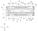
- FIG. 2 is a YZ sectional view of a center position in the X direction of the actuator shown in FIG. 1.
- FIG. 2 is an XZ sectional view of a center position in a Y direction of the actuator illustrated in FIG. 1.
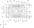
- FIG. 2 is an XY cross-sectional view of the actuator shown in FIG. 1 at a center position in a Z direction.
- FIG. 2 is a plan view in which a second case member has been removed from the actuator shown in FIG. 1.
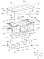
- FIG. 2 is a perspective view in which a case is disassembled from the actuator shown in FIG. 1.
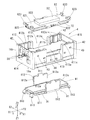
- FIG. 7 is a perspective view in which a case is removed from FIG.
- FIG. 6 is a perspective view showing a modified example of an assembled state of a yoke and the like similar to FIG. 9.
- first direction is the Z-axis direction
- second direction is the X-axis direction
- third direction is the third direction.
- the direction is referred to as a Y-axis direction, and hereinafter, a first direction Z, a second direction X, and a third direction Y will be described.
- the first direction Z, the second direction X, and the third direction Y are directions orthogonal to each other.
- X1 is attached to one side in the second direction X
- X2 is attached to the other side in the second direction X
- Y1 is attached to one side in the third direction Y
- Y2 is attached to the other side in the third direction Y.
- Z1 is added to one side in the first direction Z
- Z2 is added to the other side in the first direction Z.
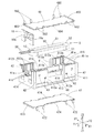
- FIG. 1 is a perspective view illustrating an appearance of an actuator 1 according to an embodiment.
- the actuator 1 shown in FIG. 1 has a rectangular parallelepiped shape whose longitudinal direction is oriented in the third direction Y, and notifies a user holding the actuator 1 of information by vibration in the second direction X. Therefore, the actuator 1 can be used as an operation member or the like of a game machine, and a new feeling can be realized by vibration or the like.
- the actuator 1 includes a support 2 including a rectangular case 3 that defines the outer shape of the actuator 1, and a second support 2 inside the case 3.
- the movable body 6 is moved by the magnetic drive circuit 1a.
- the magnetic drive circuit 1a has a coil 5 and permanent magnets 71 and 72 facing each other in the first direction Z.
- the coil 5 is provided on the support 2 side, and the permanent magnets 71 and 72 are provided on the movable body 6 side.
- the support 2 has a case 3, a coil holder 4, a coil 5, and a power supply substrate 10, and the movable body 6 includes a permanent magnet (the first magnet 71 and the first magnet 71). 2) and a yoke (first yoke 81 and second yoke 82).
- the first magnet 71 is arranged on one side Z1 in the first direction Z
- the second magnet 72 is arranged on the other side Z2.
- the movable body 6 is supported by the support 2 via connectors 91 and 92 provided between the movable body 6 and the support 2.
- the connection bodies 91 and 92 are formed of a material having at least one of elasticity and viscoelasticity.
- the movable body 6 includes a first yoke 81 made of a magnetic plate disposed on one side Z1 in the first direction Z with respect to the coil 5, and
- the first yoke 81 has a plate-like first magnet 71 held on a surface of the other side Z2 in the first direction Z so as to face the one side Z1.
- the movable body 6 is opposed to the second yoke 82 made of a magnetic plate disposed on the other side Z2 in the first direction Z with respect to the coil 5 so as to face the coil 5 on the other side Z2 in the first direction Z.
- the second yoke 82 has a plate-shaped second magnet 72 held on a surface on one side Z1 in the first direction Z.
- the movable body 6 includes a first yoke 81, a first magnet 71, a second yoke 82, and a second magnet 72.
- the first yoke 81 includes a first plate portion 811 to which the first magnet 71 is fixed, and a pair of first plate portions 811 bent from both ends in the second direction X to the other side Z2 in the first direction Z. And a connecting portion 812.
- the second yoke 82 has a second plate portion 821 to which the second magnet 72 is fixed, and an intermediate portion of the second plate portion 821 in the third direction Y has one side X1 in the second direction X and It has a pair of overhangs 822 that overhang the other side X2.
- tips of a pair of connecting portions 812 of the first yoke 81 are connected to the pair of overhang portions 822 by a method such as welding.
- first plate portion 811 of the first yoke 81 projections 813 formed by projecting both edges in the second direction X are formed.
- the tip is bent so as to face one side Z1 in the first direction Z.
- protrusions 823 formed by projecting both edges in the second direction X.
- the tip is bent so as to face the other side Z2 in the first direction Z.
- Each of the first magnet 71 and the second magnet 72 is magnetized to a different pole on one side X1 in the first direction and on the other side X2 in the first direction.
- the case 3 includes a first case member 31 located on one side Z1 in the first direction Z and a first case member 31 on the other side Z2 in the first direction Z.
- a second case member 32 overlaps the first case member 31, and a pair of side plate portions 311 provided on both sides of the first case member 31 in the second direction X, and both sides of the second case member 32 in the second direction X Are partially overlapped with each other, and the side plate portions 311 and 321 and the plate-shaped portions 312 and 322 therebetween constitute a rectangular cylindrical case 3.
- the coil holder 4, the coil 5, and the movable body 6 are accommodated between the first case member 31 and the second case member 32.
- the case 3 has openings at both ends in the third direction Y.
- the case 3 is made of a metal plate such as stainless steel, but may be made of resin.
- notches 313 and 323 are formed at both ends in the third direction Y.
- a cutout recess 324 is formed in the side plate portion 321 of the second case member 32 for disposing a part of the side plate portion 311 of the first case member 31 when the two case members 31 and 32 are overlapped.
- the two side plate portions 311 of the first case member 31 are formed with two engagement holes 314 separated from each other in the third direction Y.
- a window 315 is formed so as to be located between the engagement holes 314.
- two engagement holes 325 are formed separately in the third direction Y.
- the coil 5 is an air-core coil having an annular planar shape wound in an elliptical shape and held by the coil holder 4.
- the coil 5 has two long sides 51 extending in the third direction Y in parallel in the second direction X, and two arc-shaped short sides connecting both ends of the two long sides 51 in the third direction Y.
- the first magnet 71 faces the long side portion 51 on one side Z1 in the first direction Z
- the second magnet 72 faces the other side Z2 in the first direction Z with the coil 5 configured as described above. are doing.
- the coil holder 4 has an overall shape of a rectangular parallelepiped housed in a rectangular cylindrical case 3, and has an intermediate portion in the first direction Z. Except for the above, the one side Z1 and the other side Z2 are formed into a shape that is cut out, so that a coil arrangement hole 410 formed of an oval through hole in which the coil 5 is arranged inside is located at an intermediate position in the first direction Z. It has a plate portion 41 that opens in the first direction Z. Further, on one side X1 and the other side X2 in the second direction X, side plate portions 411 and 412 extending to both the one side Z1 and the other side Z2 in the first direction Z of the plate portion 41 are formed.
- the side plate portions 411 and 412 have an opening 413 formed at an intermediate position in the third direction Y so as to cut off the other side Z2 in the first direction Z, and the second portion of the plate portion 41 is formed in the opening 413.
- the end faces on both sides in the direction X are exposed.
- the side plate portions 411 and 412 have a shape separated in the third direction Y on the other side Z2 in the first direction Z, and have a shape connected by the connecting portion 44 on one side Z1.
- a side plate portion 414 is formed so as to extend from the plate portion 41 to one side Z1 in the first direction Z, and on the other side Y2 in the third direction Y. And a side plate portion 415 extending to both one side Z1 and the other side Z2 of the plate portion 41 in the first direction Z. Further, a plurality of groove-shaped recesses 411a and 412a along the first direction Z are formed on the inner surfaces of the side plate portions 411 and 412 arranged on both sides in the second direction X, and a plurality of recesses on the surface of the plate portion 41 are formed. It communicates with each of the groove-shaped concave portions 41a.
- prismatic reinforcing portions 42 extending to one side Z ⁇ b> 1 and the other side Z ⁇ b> 2 in the first direction Z are formed, and the first case member 31 and the second case member 32 are formed.
- the reinforcing portion 42 comes into engagement with the notches 313 and 323 formed in the pair of side plate portions 311 of the first case member 31 and the pair of side plate portions 321 of the second case member 32.
- a claw portion 43 is formed in which an engagement hole 314 of the first case member 31 and an engagement hole 325 of the second case member 32 are engaged.
- the support 2 has a first plate 47 overlapping the coil arrangement hole 410 of the coil holder 4 and the plate portion 41 from one side Z1 in the first direction Z, and is filled at least in the air core portion 50 of the coil 5.
- the coil 5 is fixed to the first plate 47 and the plate portion 41 by an adhesive. Therefore, the coil 5 is opposed to the first magnet 71 in the first direction Z via the first plate 47. Further, the first plate 47 is fixed to the plate portion 41 by an adhesive.
- the support 2 has a second plate 48 that overlaps the coil arrangement hole 410 and the plate portion 41 from the other side Z2 in the first direction Z, and at least the adhesive filled in the air core portion 50 of the coil 5.
- the coil 5 is fixed to the second plate 48 by an adhesive composed of Therefore, the coil 5 is opposed to the second magnet 72 via the second plate 48 in the first direction Z. Further, the second plate 48 is fixed to the plate portion 41 by an adhesive.
- the concave portion 41a and the like formed in the plate portion 41 serve as a reservoir for the adhesive.
- the first plate 47 and the second plate 48 are made of a non-magnetic material.
- the first plate 47 and the second plate 48 are made of a metal plate. More specifically, the first plate 47 and the second plate 48 are made of a non-magnetic stainless steel plate.
- the first plate 47 has a claw-shaped convex portion 472 projecting obliquely from both sides in the second direction X to one side Z1 in the first direction Z.
- the second plate 48 has a claw-shaped convex portion 482 projecting obliquely from both sides in the second direction X to the other side Z2 in the first direction Z.
- the protrusions 472 and 482 elastically abut inside groove-shaped recesses 411 a and 412 a formed on the inner surfaces of the side plates 411 and 412, and are held by the coil holder 4.
- the first plate 47 has a bent portion 473 bent at one end Z1 in the first direction Z at both ends in the third direction Y, and a bent portion 474 bent at the other end Z2 in the first direction Z at both ends in the second direction X.
- the second plate 48 has a bent portion 483 bent at both ends in the third direction Y to the other side Z2 in the first direction Z, and a bent portion 484 bent at both ends in the second direction X to one side Z1 in the first direction Z. And Therefore, the bending strength of the first plate 47 and the second plate 48 is increased by the bent portions 473, 474, 483, and 484.
- the coil 5 is arranged inside the coil arrangement hole 410 penetrating the plate portion 41 of the coil holder 4 in the first direction Z, and the coil arrangement hole 410 and the plate portion 41
- the first plate 47 is disposed so as to overlap from one side Z1 in the first direction Z. For this reason, when the adhesive is filled in the air core 50 of the coil 5, the adhesive is applied between the coil 5 and the coil holder 4, between the coil 5 and the first plate 47, and between the first plate 47 and the coil holder. Flows in between 4. Therefore, when the adhesive is cured, the coil 5, the first plate 47, and the coil holder 4 are fixed by the adhesive.
- the coil 5 arranged in the coil arrangement hole 410 of the coil holder 4 can be properly bonded to the coil holder 4. Further, a first plate 47 is interposed between the first magnet 71 and the coil 5. Therefore, even when the movable body 6 moves to one side Z1 in the first direction Z, the first magnet 71 and the coil 5 do not directly come into contact with each other, so that the coil 5 is hardly damaged.
- the adhesive is applied between the coil 5 and the coil holder 4, between the coil 5 and the first plate 47, And flows smoothly between the first plate 47 and the coil holder 4, and also flows between the coil 5 and the second plate 48 and between the second plate 48 and the coil holder 4. Therefore, when the adhesive is cured, the coil 5, the first plate 47, the second plate 48, and the coil holder 4 are fixed by the adhesive. In this state, the second plate 48 is interposed between the second magnet 72 and the coil 5. For this reason, even when the movable body 6 moves to the other side Z2 in the first direction Z, the second magnet 72 and the coil 5 do not directly contact with each other, so that the coil 5 is not easily damaged.
- the first plate 47 and the second plate 48 are made of a non-magnetic material, the magnetic flux from the first magnet 71 and the magnetic flux from the second magnet 72 are affected by the first plate 47 and the second plate 48. Instead, it is linked with the coil 5. Further, since the first plate 47 and the second plate 48 are made of a metal plate, heat generated in the coil 5 can be efficiently released through the first plate 47 and the second plate 48. Further, since the first plate 47 and the second plate 48 are made of a stainless steel plate, the first plate 47 and the second plate 48 have sufficient strength even when the plate thickness is small.
- the coil holder 4 has concave portions 411 a and 421 a that engage with the claw-shaped protrusion 472 of the first plate 47 or the protrusion 482 of the second plate 48 to hold the first plate 47. Therefore, there is no need to support the first plate 47 and the second plate 48 with a jig or the like until the adhesive is cured.
- connection bodies 91 and 92 (Configuration of the connection bodies 91 and 92) As shown in FIGS. 2, 3, 7 and 9, the movable body 6 is connected to the second body X and the third direction Y by connecting bodies 91 and 92 provided between the movable body 6 and the support 2. It is movably supported.
- the connecting body 91 is provided at a portion where the first plate portion 811 of the first yoke 81 and the plate portion 312 of the first case member 31 face each other in the first direction Z.
- the connection body 92 is provided at a portion where the second plate portion 821 of the second yoke 82 and the plate portion 322 of the second case member 32 face each other in the first direction Z. More specifically, the connecting body 91 is formed in a rectangular parallelepiped shape, and the center of the first plate portion 811 of the first yoke 81 in the second direction X and the third direction Y and the plate shape of the first case member 31 are formed.
- the portion 312 is provided at a portion facing the first direction Z, and both end surfaces of the connector 91 in the first direction Z are fixed to the first plate portion 811 and the plate portion 312, respectively.
- the connection body 92 is formed in a rectangular parallelepiped shape, and the center of the second plate portion 821 of the second yoke 82 in the second direction X and the third direction Y and the plate-shaped portion 322 of the second case member 32 are the first.
- the connector 92 is provided at a portion facing in the direction Z, and both end faces in the first direction Z of the connector 92 are fixed to the second plate portion 821 and the plate-shaped portion 322, respectively.
- connection bodies 91 and 92 are viscoelastic members. Therefore, the movable body 6 can be supported movably in the second direction X without using a plate spring or the like.
- the viscoelasticity is a property combining both viscosity and elasticity, and is a property remarkably observed in a polymer material such as a gel-like member, plastic, and rubber. Therefore, various gel members can be used as the viscoelastic member.
- the viscoelastic member natural rubber, diene rubber (for example, styrene / butadiene rubber, isoprene rubber, butadiene rubber), chloroprene rubber, acrylonitrile / butadiene rubber, and the like, non-diene rubber (for example, butyl rubber, ethylene / propylene)
- diene rubber for example, styrene / butadiene rubber, isoprene rubber, butadiene rubber
- chloroprene rubber acrylonitrile / butadiene rubber, and the like
- non-diene rubber for example, butyl rubber, ethylene / propylene
- Various rubber materials such as rubber, ethylene / propylene / diene rubber, urethane rubber, silicone rubber, fluorine rubber, and thermoplastic elastomers, and modified materials thereof may be used.
- the connectors 91 and 92 are made of silicone gel having a penetration of 90 to 110 degrees.
- the penetration is defined as the depth of penetration of a 1/4 cone needle with a total load of 9.38 g at 25 ° C for 5 seconds as specified in JIS-K-2207 and JIS-K-2220. In units of 1/10 mm, the smaller the value, the harder it is.
- the fixing of the connectors 91 and 92 to the first yoke 81 and the second yoke 82 and the fixing of the connectors 91 and 92 to the first case member 31 and the second case member 32 are performed by using an adhesive, an adhesive, or the like. Alternatively, it is performed by utilizing the adhesiveness of the silicone gel.
- the connectors 91 and 92 are provided between the movable body 6 and the support 2, resonance of the movable body 6 can be suppressed.
- the connecting bodies 91 and 92 are provided at positions opposed to each other in the first direction Z that intersects the second direction X (the vibration direction) between the support 2 and the movable body 6, When vibrated in the second direction X, it is deformed in the shear direction to prevent resonance. For this reason, even if the movable body 6 vibrates in the second direction X, the change in the elastic modulus of the connecting bodies 91 and 92 is small, so that the resonance of the movable body 6 can be effectively suppressed.
- connection bodies are viscoelastic members (plate-like gel-like members) and have linear or non-linear expansion / contraction characteristics depending on the expansion / contraction direction.
- the connecting bodies 91 and 92 are compressed in the thickness direction (axial direction) by being pressed in the thickness direction (axial direction)
- they have expansion / contraction characteristics in which a non-linear component is larger than a linear component (spring coefficient).
- spring coefficient When it is stretched by being pulled (in the axial direction), it has expansion and contraction characteristics in which a linear component (spring coefficient) is larger than a non-linear component (spring coefficient).
- the connecting bodies 91 and 92 are deformed in a direction (shear direction) intersecting with the thickness direction (axial direction), they are deformed in a direction in which the connecting bodies 91 and 92 are pulled and extended even if they move in any direction.
- the linear component (spring coefficient) has a larger deformation characteristic than the component (spring coefficient).
- the connecting bodies 91 and 92 are configured to deform in the shear direction. Therefore, in the connecting bodies 91 and 92, when the movable body 6 vibrates in the second direction X, the spring force due to the movement direction becomes constant. Therefore, the reproducibility of the vibration acceleration with respect to the input signal can be improved by using the spring elements of the connecting bodies 91 and 92 in the shear direction, so that the vibration can be realized with subtle nuances.
- the connecting bodies 91 and 92 are both connected to the movable body 6 and the support 2 by a method such as bonding on both surfaces in the first direction Z. Therefore, since the connecting bodies 91 and 92 reliably follow the movement of the movable body 6, resonance of the movable body 6 can be effectively prevented. In this case, the connecting bodies 91 and 92 are in a state of being compressed in the first direction Z between the support 2 and the movable body 6. Therefore, since the connecting bodies 91 and 92 reliably follow the movement of the movable body 6, resonance of the movable body 6 can be effectively prevented.
- the connecting members 91 and 92 are compressed to a thickness that is smaller by about 10% than the thickness in a free state. 2 and 3, the ends of the connecting bodies 91 and 92 are shown as overlapping the first yoke 81 or the second yoke 82, but the overlapping portion is a compression margin of the connecting bodies 91 and 92. Show.
- a stopper mechanism is provided to limit the movable range when the movable body 6 moves in the first direction Z, the second direction X, and the third direction Y due to an external impact. More specifically, as described above, a protrusion 813 is formed on one side Z1 of the first plate portion 811 of the first yoke 81 in the first direction Z so as to project toward the plate-like portion 312 of the first case member 31. A projection 823 is formed on the other side Z2 of the second yoke 82 in the first direction Z of the second plate 821 toward the plate 322 of the second case member 32.
- a first stopper mechanism for limiting a moving range is configured.
- the protrusions 813 and 823 are point-symmetric with respect to the center of gravity C of the movable body 6. Is provided.
- first plate portion 811 and the second plate portion 821 of each of the yokes 81 and 82 the figure center when viewed from one side Z1 or the other side Z2 of the plate portions 811 and 821 in the first direction Z (FIG.
- the projections 813 and 823 are provided point-symmetrically with respect to the position indicated by the symbol C of No. 5).
- the height H of each of the protrusions 813 and 823 is the same for each of the yokes 81 and 82.
- the heights H of the projections 813 and 823 are provided between the connecting body 91 provided between the first yoke 81 and the first case member 31 and between the second yoke 82 and the second case member 32.
- the connecting body 92 Is smaller than the thickness of the connecting body 92 (the interval T between the plate portions 811 and 821 of the yokes 81 and 82 and the plate portions 312 and 322 of the case members 31 and 32), but the convex portion 813 The distance between the plate portions 811 and 821 of the yokes 81 and 82 and the plate portions 312 and 322 of the case members 31 and 32 when the 823 contacts the plate portions 312 and 322 (that is, the protrusions 813 and 823). Even when the connection bodies 91 and 92 are compressed to the height H), the connection bodies 91 and 92 are set to such an extent that the functions of the connection bodies 91 and 92 can be restored to their original positions without being destroyed. In this case, the moving range of the movable body 6 in the first direction Z is limited to the range of g1 on one side Z1 and the other side Z2 as shown in FIG.
- both end surfaces in the second direction X of the first plate portion 811 of the first yoke 81 and the second plate portion 821 of the second yoke 82 are connected to the inner surfaces 411 b of the side plate portions 411 and 412 of the coil holder 4. , 412b in the second direction X. Therefore, when the movable body 6 moves in the second direction X due to an external impact, the end surfaces of the respective plate portions 811 and 812 and the inner surfaces 411b and 412b of the side plate portions 411 and 412 abut on the movable body 6.
- the second stopper mechanism defines a movable range in the second direction X. In the second stopper mechanism, as shown in FIG.
- the movable range of the movable body 6 in the second direction X is limited to a range of g2 on one side X1 and the other side X2.
- the pair of connecting portions 812 of the first yoke 81 and the overhanging portions 822 of the second yoke 82 are respectively disposed in openings 413 formed in the side plates 411 and 412 of the coil holder 4.
- Projections 812 a are formed at both ends in the third direction Y of the connecting portion 812, and the tips of the projections 812 a are attached to the end surfaces 413 a of the side plates 411 and 421 forming the opening 413. Are facing each other.
- the third stopper mechanism defines a range.
- the moving range of the movable body 6 in the third direction Y is limited to a range of g3 on one side Y1 and the other side Y2.
- the power supply substrate 10 is provided at one end Y1 of the coil holder 4 in the third direction Y.
- a coil wire 56 constituting the coil 5 is connected to the lands 16a and 16b of the power supply board 10 by soldering or the like.
- the power supply substrate 10 is a rigid substrate.
- the power supply substrate 10 is held in an opening surrounded by the side plates 411, 412, and 414 on one side in the third direction Y of the coil holder 4.
- the coil wire 56 passes from the coil 5 in the third direction Y through two guide grooves 41c formed on the other side Z2 of the end of the plate portion 41 of the coil holder 4 in the first direction Z. After being pulled out to one side Y1 of the first direction Z, it extends from one side Z1 in the first direction Z to the other side Z2 and is connected to the power supply board 10.
- the coil holder 4 includes a pair of side plates 411 and 412 opposed to each other in the second direction X at one end Y1 in the second direction Y and a pair extending to one side Z1 in the first direction Z. Are formed, and both ends of the power supply substrate 10 on both sides in the second direction X are fitted inside the slits 411t and 412t, respectively. Accordingly, the power supply board 10 is held by the coil holder 4 along the side plate 414 of the coil holder 4 at a position exposed from the case 3. In the present embodiment, after the end of the power supply substrate 10 is fitted into the slits 411t and 412t, the coil holder 4 and the power supply substrate 10 are further fixed with an adhesive to suppress vibration of the power supply substrate 10.
- the power supply board 10 is held by the coil holder 4 covered by the case 3, it is difficult for an impact at the time of drop to propagate to the power supply board 10 via the case 3.
- the power supply board 10 moves together with the coil holder 4, so that the situation where the coil wire 56 is pulled hardly occurs. Therefore, it is unlikely that the coil wire 56 will be disconnected due to the impact at the time of dropping, so that the drop impact resistance can be improved.
- the power supply board 10 is provided along the side surface of the coil holder 4. For this reason, a situation in which a shock at the time of a drop is directly applied to the power supply board 10 is unlikely to occur, and a situation in which the coil wire 56 is disconnected due to a shock at the time of a fall is less likely to occur.
- the distance L between the power supply substrate 10 and the movable body 6 is determined by the distance between the protrusion 812 a of the connecting portion 812 of the yoke 81, 82, which is the third stopper mechanism, and the opening of the side plate portions 411, 412 of the coil holder 4.
- the distance g3 from the end surface 413a facing the portion 413 is set to be larger than the distance g3. Therefore, even if the movable body 6 moves due to the impact at the time of dropping and hits the coil holder 4 and the movable body 6, the movable body 6 does not collide with the power supply board 10, so that the impact at that time hardly propagates to the power supply board 10. Therefore, it is unlikely that the coil wire 56 will be disconnected due to the impact at the time of dropping.
- the actuator 1 of the present embodiment when power is supplied to the coil 5 from the outside (upper device) via the power supply substrate 10, the movable body 6 is driven by the magnetic drive circuit 1 a including the coil 5, the first magnet 71, and the second magnet 72. Reciprocates in the second direction X. Therefore, a user holding the actuator 1 can obtain information by the vibration from the actuator 1. At this time, the frequency of the signal waveform applied to the coil 5 is changed according to the information to be transmitted. The polarity of the signal waveform applied to the coil 5 is inverted. At this time, a difference between the change in the voltage and the change in the voltage between the negative period and the positive period of the drive signal is provided.
- the movable range of the movable body 6 is regulated by the second stopper mechanism including the inner surfaces 411b and 412b.
- the movable range of the movable body 6 is regulated by the third stopper mechanism 413a. In the movement in the second direction X and the third direction Y, the connectors 91 and 92 are deformed in the shearing direction.
- the connecting body disposed between the first yoke 81 and the first case member 31 When the movable body 6 moves in the first direction Z due to an external impact, or when the movable body 6 moves to one side Z1 of the movable body 6, the connecting body disposed between the first yoke 81 and the first case member 31 The connection 91 disposed between the second yoke 82 and the second case member 32 is stretched. Among these, the connecting body 91 disposed between the first yoke 81 and the first case member 31 regulates the compression range when the convex portion 813 of the first yoke 81 comes into contact with the first case member 31. And will not be crushed anymore.
- the connecting body 92 disposed between the second yoke 82 and the second case member 32 is compressed, and the first yoke 81
- the connecting body 91 disposed between the first case member 31 and the first case member 31 is stretched.
- the connection range of the connector 92 disposed between the second yoke 82 and the second case member 32 is restricted when the convex portion 823 of the second yoke 82 contacts the second case member 32. And will not be crushed anymore.
- the compression range of the connectors 91 and 92 is limited by the first stopper mechanism to a range in which the connectors 91 and 92 can be restored, and the function is effectively maintained. can do.
- the moving range in the first direction Z can be appropriately set by adjusting the height H of the convex portions 813 and 823.
- the first yoke 81 and the second yoke 82 are provided with the projections 813 and 823.
- the first yoke and the second yoke are not provided with the projections, but are formed by members different from these yokes.
- the protrusions may be formed by the members described above and fixed to the first plate portion of the first yoke and the second plate portion of the second yoke, respectively.
- the convex portion may be formed of a nonmagnetic material, for example, a resin.
- FIG. 10 shows an example in which a convex portion is formed on an auxiliary yoke member made of a magnetic material manufactured separately from the first yoke and the second yoke.
- the first plate portion 811 of the first yoke 81 and the second plate portion 821 of the second yoke 82 are formed in a flat plate shape having no projection.
- the auxiliary yoke members 85 and 86 are generally formed in a plate shape similarly to the first plate portion 811 and the second plate portion 821, but are provided at both ends in the third direction Y with both edges in the second direction X. Are formed to form protrusions 851 and 861. Then, the auxiliary yoke member 85 is fixed on one side Z1 of the first plate 811 of the first yoke 81 in the first direction Z so as to overlap, and the other of the second plate 821 of the second yoke 82 in the first direction Z. The auxiliary yoke member 86 is fixed on the side Z2 so as to overlap.
- each of the protrusions 851 and 861 is bent so that the tip is directed to one side Z ⁇ b> 1 in the first direction Z, and is fixed to the second yoke 82.
- the auxiliary yoke member 86 is bent such that its tip is directed to the other side Z2 in the first direction Z.
- the convex portions 851 and 861 of the auxiliary yoke members 85 and 86 face the first case member 31 or the second case member 32, and the plate-like portions of the convex portions 851 and 861 and the case members 31 and 32 are formed.
- a first stopper mechanism is configured between the portions (receiving portions) 312 and 322. Also in this case, the height of the projections 851 and 861 can be restored to the original state even when the connectors 91 and 92 are compressed until the tips of the projections 851 and 861 abut on the case 3. It is set to the size of about.
- any one of the protrusions 851 and 861 abuts on the case 3 and the connecting bodies 91 and 92 are crushed and their functions are impaired.
- two connecting bodies 91 and 92 are provided on each of the auxiliary yoke members 85 and 86 at intervals in the third direction Y. Further, since the auxiliary yoke members 85 and 86 are fixed to the first yoke 81 and the second yoke 82, magnetic flux from the magnets 71 and 72 can be concentrated to prevent magnetic leakage from the yokes 81 and 82. it can.
- the weights of the yokes 81, 82 are increased by the amount of the auxiliary yoke members 85, 86. Therefore, by appropriately adjusting the weights of the auxiliary yoke members 85 and 86, the weight of the movable body 6 can be adjusted, and an actuator having desired vibration characteristics can be designed.
- the auxiliary yoke members 85 and 86 are formed in a plate shape and are overlapped only on the first plate portion 811 of the first yoke 81 and the second plate portion 821 of the second yoke. And the dimensions in the second direction X and the third direction do not change. It is conceivable to increase the thickness of the first yoke and the second yoke by the thickness of the auxiliary yoke members 85 and 86. In this case, the dimensions are not only in the first direction Z but also in the second direction X. Increase the size of the device. By stacking and fixing the plate-like auxiliary yoke members 85 and 86 on the first plate portion 811 and the second plate portion 821, it is possible to suppress an increase in the size of the device.
- the coil holder 4 and the coil 5 are provided on the support 2, and the permanent magnets (the first magnet 71 and the second magnet 72) and the yokes (the first yoke 81 and the second yoke 82) are movable.
- the coil holder 4 and the coil 5 are provided on the movable body 6, and the permanent magnet (the first magnet 71 and the second magnet 72) and the yoke (the first yoke 81 and the second yoke 82) are provided on the support 2. You may apply to the provided actuator.
Landscapes
- Engineering & Computer Science (AREA)
- Physics & Mathematics (AREA)
- Electromagnetism (AREA)
- Mechanical Engineering (AREA)
- Power Engineering (AREA)
- Apparatuses For Generation Of Mechanical Vibrations (AREA)
- Reciprocating, Oscillating Or Vibrating Motors (AREA)
Abstract
落下衝撃等の際の可動体の移動を規制して接続体の機能を有効に保護しつつ、装置の大型化を抑制する。支持体と、支持体に移動可能に支持された可動体と、支持体又は前記可動体の一方側部材に設けられたコイル、および支持体又は可動体の他方側部材に設けられて前記コイルに第1方向で対向する第1磁石を備え、可動体を第1方向に対して交差する第2方向に駆動する磁気駆動回路と、を有し、支持体と可動体とが第1方向で対向する位置の間に、支持体と可動体との双方に接するように配置された弾性材料又は粘弾性材料からなる接続体と、第1方向に沿う可動体の移動範囲を接続体が復元可能な範囲で規制するストッパ機構とを備えている。
Description
本発明は、各種振動を発生させるアクチュエータに関するものである。
ゲーム機の操作部材等に用いられ、各種振動を発生させるアクチュエータとして、特許文献1に記載の磁気駆動機構によって振動を発生させる機器が提案されている。このアクチュエータは、第1方向で対向するコイルおよび磁石を備えた磁気駆動回路によって可動体を支持体に対して第1方向に対して交差する第2方向又は第3方向に振動させる。この特許文献1記載の構造の場合、磁石は、支持体に設けた磁性材料からなるヨークに保持されている。また、支持体と可動体との間には、両者を接続するようにゲル状ダンパー部材からなる接続体が設けられている。
特許文献1記載のアクチュエータにおいて、落下衝撃等によって可動体が移動する場合、振動面に沿う方向(第2方向又は第3方向)の移動に対しては、可動体が支持体に当接することで移動範囲が制限され、その際、接続体はせん断方向に変形する。これに対して、落下衝撃等によって可動体が振動面と直交する第1方向に移動する際、接続体は、圧縮又は引き伸ばす方向に変形させられる。この接続体は弾性又は粘弾性を有する素材によって形成されており、落下衝撃によって強く圧し潰されると、その機能が破壊されるおそれがある。
特許文献1の構造の場合、アクチュエータの中心から四つの磁気駆動回路が90°ずつ間隔をおいて配置され、これら磁気駆動回路の間(つまり45°の方向)およびアクチュエータの中心位置に、比較的厚肉の接続体が設けられている。このため、落下衝撃によって可動体が第1方向に移動したとしても、接続体が強く圧し潰されることは少ない。
しかしながら、特許文献1の構造であると、磁気駆動回路の周囲に接続体を設けるスペースを確保する必要があるため、アクチュエータが振動面に沿う方向に大きくなる。
特許文献1の構造の場合、アクチュエータの中心から四つの磁気駆動回路が90°ずつ間隔をおいて配置され、これら磁気駆動回路の間(つまり45°の方向)およびアクチュエータの中心位置に、比較的厚肉の接続体が設けられている。このため、落下衝撃によって可動体が第1方向に移動したとしても、接続体が強く圧し潰されることは少ない。
しかしながら、特許文献1の構造であると、磁気駆動回路の周囲に接続体を設けるスペースを確保する必要があるため、アクチュエータが振動面に沿う方向に大きくなる。
本発明は、このような事情に鑑みてなされたもので、落下衝撃等の際の可動体の移動を規制して接続体の機能を有効に保護しつつ、装置の大型化を抑制することを目的とする。
本発明のアクチュエータは、支持体と、前記支持体に移動可能に支持された可動体と、前記支持体又は前記可動体の一方側部材に設けられたコイル、および前記支持体又は前記可動体の他方側部材に設けられて前記コイルに第1方向で対向する第1磁石を備え、前記可動体を前記第1方向に対して交差する第2方向に駆動する磁気駆動回路と、を有し、前記支持体と前記可動体とが前記第1方向で対向する位置の間に、前記支持体と前記可動体との双方に接するように配置された弾性又は粘弾性を有する接続体と、前記第1方向に沿う前記可動体の移動範囲を前記接続体が復元可能な範囲で規制するストッパ機構とを備えている。
本発明では、可動体と支持体との対向方向(第1方向)の移動を規制するストッパ機構を設けたことにより、落下衝撃等によって可動体と支持体とが第1方向に移動して接続体が圧縮変形される場合でも、接続体が押し潰されることなく、復元可能な範囲に可動体と支持体との相対移動範囲が規制されるので、接続体の機能が破壊されることが防止される。
本発明のアクチュエータは、前記支持体に前記コイルが設けられ、前記可動体に、前記第1磁石と該第1磁石を固定する磁性材料からなるヨークとが設けられ、該ヨークの前記第1磁石が固定されている側とは反対側と前記支持体との間に前記接続体が設けられ、前記ストッパ機構は、前記ヨークに前記第1方向に沿って設けられた凸部と、前記支持体に設けられ、前記凸部を当接する受け部とからなるものとしてよい。
ヨークに重ねて接続体を設ける場合、ヨークとコイルとの対向部間に接続体を設ける場合は、ヨークに第1磁石が設けられているため、接続体が押し潰されることは少ないが、第1磁石と接続体とを振動面方向に並んで配置させることになるため、設置スペースの増大を招く。装置の大型化を抑制しようとすると、第1磁石が小さくなって駆動力が低減する。これに対して、ヨークと支持体との間に接続体を配置する場合、ヨークとコイルとの間のスペースを振動面方向に広く確保することが可能になり、装置の大型化を招くことなく第1磁石を大きくすることができ、磁気駆動回路の駆動力を増大させることが可能になる。この場合、ストッパ機構がないと、ヨークと支持体との間で接続体が押し潰されるため、接続体が破壊されるおそれがある。これを避けるために接続体を厚肉にすると装置が大型化する。
本発明では、ヨークの凸部が支持体の受け部に当接するストッパ機構を設けることにより、接続体が押し潰されることなく、復元可能な範囲に制限される。これにより、装置の大型化を抑制しつつ駆動力の増大を図り、かつ接続体を確実に保護することができる。
本発明では、ヨークの凸部が支持体の受け部に当接するストッパ機構を設けることにより、接続体が押し潰されることなく、復元可能な範囲に制限される。これにより、装置の大型化を抑制しつつ駆動力の増大を図り、かつ接続体を確実に保護することができる。
本発明のアクチュエータは、前記凸部は前記ヨークの一部を前記支持体に向けて屈曲させて形成されているとよい。
ヨークは磁気駆動回路の一部を構成する部材であり、比較的厚肉に形成されるので、その一部を屈曲させて凸部を形成すれば、落下衝撃時に変形しにくい凸部を得ることができる。
ヨークは磁気駆動回路の一部を構成する部材であり、比較的厚肉に形成されるので、その一部を屈曲させて凸部を形成すれば、落下衝撃時に変形しにくい凸部を得ることができる。
本発明のアクチュエータは、前記凸部は、前記ヨークとは別部材からなり、前記ヨークの前記支持体と対向する側の表面に固定されていてもよい。
凸部をヨークとは別部材により形成したので、ヨークに固定することにより、可動体の重量を増加させることができる。このため、この凸部を有する別部材の大きさを適宜に設定することにより、可動体の重量を調整することができ、所望の振動特性のアクチュエータを得ることができる。
凸部をヨークとは別部材により形成したので、ヨークに固定することにより、可動体の重量を増加させることができる。このため、この凸部を有する別部材の大きさを適宜に設定することにより、可動体の重量を調整することができ、所望の振動特性のアクチュエータを得ることができる。
本発明のアクチュエータは、前記凸部は、前記第1方向の一方側から視たときに前記可動体の重心に対して点対称に複数設けられているとよい。
凸部が重心に対して点対称に設けられているので、重量バランスが均衡して、安定した振動を行わせることができる。
凸部が重心に対して点対称に設けられているので、重量バランスが均衡して、安定した振動を行わせることができる。
アクチュエータのさらに他の一つの実施態様として、前記可動体に、前記第1磁石と対向する側とは反対側で前記コイルに対向する第2磁石が設けられ、前記ヨークは、前記第1磁石を固定する第1板部と、前記第2磁石を固定する第2板部とを有し、前記支持体は前記ヨークの外側を囲むケースを有し、前記接続体は、前記第1板部と前記ケースとの間、および前記第2板部と前記ケースとの間にそれぞれ設けられ、前記凸部は、前記第1板部および前記第2板部にそれぞれ設けられていてもよい。
このアクチュエータは、コイルを挟んで両側で対称な構造となってバランスがとれるため、安定した振動を生じさせることができる。その場合も、落下衝撃時に第1方向の一方側および他方側の両方向で接続体を保護することができる。
本発明のアクチュエータは、前記支持体と前記可動体との間に、前記第2方向の前記可動体の可動範囲を規制する第2ストッパ機構が設けられているとよい。また、前記支持体と前記可動体との間に、前記第1方向および前記第2方向の両方向に直交する第3方向の可動範囲を規制する第3ストッパ機構が設けられているとよい。
第2ストッパ機構又は第3ストッパ機構によって可動体の移動範囲が規制されるので、落下衝撃等による破損の発生を有効に防止することができる。
第2ストッパ機構又は第3ストッパ機構によって可動体の移動範囲が規制されるので、落下衝撃等による破損の発生を有効に防止することができる。
本発明によれば、落下衝撃等の際の可動体の移動を規制して接続体の機能を有効に保護しつつ、装置の大型化を抑制することができる。
以下、本発明に係るアクチュエータの実施形態について図面を参照しながら説明する。
以下の説明において、互いに交差する3つの方向を各々、第1方向、第2方向および第3方向とし、本実施形態では、第1方向をZ軸方向、第2方向をX軸方向、第3方向をY軸方向として、以降、第1方向Z、第2方向X、第3方向Yとして説明する。また、第1方向Z、第2方向Xおよび第3方向Yは、互いに直交する方向である。また、第2方向Xの一方側にX1を付し、第2方向Xの他方側にX2を付し、第3方向Yの一方側にY1を付し、第3方向Yの他方側にY2を付し、第1方向Zの一方側にZ1を付し、第1方向Zの他方側にZ2を付して説明する。
以下の説明において、互いに交差する3つの方向を各々、第1方向、第2方向および第3方向とし、本実施形態では、第1方向をZ軸方向、第2方向をX軸方向、第3方向をY軸方向として、以降、第1方向Z、第2方向X、第3方向Yとして説明する。また、第1方向Z、第2方向Xおよび第3方向Yは、互いに直交する方向である。また、第2方向Xの一方側にX1を付し、第2方向Xの他方側にX2を付し、第3方向Yの一方側にY1を付し、第3方向Yの他方側にY2を付し、第1方向Zの一方側にZ1を付し、第1方向Zの他方側にZ2を付して説明する。
(全体構成)
図1は、一実施形態のアクチュエータ1の外観を示す斜視図である。
この図1に示すアクチュエータ1は、第3方向Yに長手方向を向けた直方体形状を有しており、アクチュエータ1を手にした利用者に対して第2方向Xの振動によって情報を報知する。従って、アクチュエータ1は、ゲーム機の操作部材等として利用することができ、振動等によって新たな感覚を実感することができる。
図2、図3、および図5に示すように、アクチュエータ1は、アクチュエータ1の外形を規定する角形のケース3等を含む支持体2と、ケース3の内部で支持体2に対して第2方向Xに移動可能に支持された可動体6と、可動体6を支持体2に対して第2方向Xに移動させる磁気駆動回路1aとを有しており、磁気駆動回路1aによって可動体6が第2方向Xに振動することによって情報を出力する。磁気駆動回路1aは、第1方向Zで対向するコイル5と永久磁石71,72とを有する。本形態では、コイル5が支持体2の側に設けられ、永久磁石71,72が可動体6の側に設けられている。
本形態においては、以下に説明するように、支持体2は、ケース3、コイルホルダ4、コイル5、給電基板10を有しており、可動体6は、永久磁石(第1磁石71および第2磁石72)、およびヨーク(第1ヨーク81および第2ヨーク82)を有している。この場合、コイルホルダ4に保持されたコイル5に対して、第1方向Zの一方側Z1に第1磁石71が配置され、他方側Z2に第2磁石72が配置される。また、可動体6は、可動体6と支持体2との間に設けられた接続体91、92を介して支持体2に支持されている。
接続体91、92は、弾性または粘弾性の少なくとも一方を備えた材料により形成されている。
図1は、一実施形態のアクチュエータ1の外観を示す斜視図である。
この図1に示すアクチュエータ1は、第3方向Yに長手方向を向けた直方体形状を有しており、アクチュエータ1を手にした利用者に対して第2方向Xの振動によって情報を報知する。従って、アクチュエータ1は、ゲーム機の操作部材等として利用することができ、振動等によって新たな感覚を実感することができる。
図2、図3、および図5に示すように、アクチュエータ1は、アクチュエータ1の外形を規定する角形のケース3等を含む支持体2と、ケース3の内部で支持体2に対して第2方向Xに移動可能に支持された可動体6と、可動体6を支持体2に対して第2方向Xに移動させる磁気駆動回路1aとを有しており、磁気駆動回路1aによって可動体6が第2方向Xに振動することによって情報を出力する。磁気駆動回路1aは、第1方向Zで対向するコイル5と永久磁石71,72とを有する。本形態では、コイル5が支持体2の側に設けられ、永久磁石71,72が可動体6の側に設けられている。
本形態においては、以下に説明するように、支持体2は、ケース3、コイルホルダ4、コイル5、給電基板10を有しており、可動体6は、永久磁石(第1磁石71および第2磁石72)、およびヨーク(第1ヨーク81および第2ヨーク82)を有している。この場合、コイルホルダ4に保持されたコイル5に対して、第1方向Zの一方側Z1に第1磁石71が配置され、他方側Z2に第2磁石72が配置される。また、可動体6は、可動体6と支持体2との間に設けられた接続体91、92を介して支持体2に支持されている。
接続体91、92は、弾性または粘弾性の少なくとも一方を備えた材料により形成されている。
(可動体6の構成)
図2および図3に示すように、可動体6は、コイル5に対して第1方向Zの一方側Z1に配置された磁性板からなる第1ヨーク81と、コイル5に第1方向Zの一方側Z1で対向するように第1ヨーク81の第1方向Zの他方側Z2の面に保持された平板状の第1磁石71とを有している。また、可動体6は、コイル5に対して第1方向Zの他方側Z2に配置された磁性板からなる第2ヨーク82と、コイル5に第1方向Zの他方側Z2で対向するように第2ヨーク82の第1方向Zの一方側Z1の面に保持された平板状の第2磁石72とを有している。本形態において、可動体6は、第1ヨーク81、第1磁石71、第2ヨーク82、および第2磁石72によって構成されている。
図2および図3に示すように、可動体6は、コイル5に対して第1方向Zの一方側Z1に配置された磁性板からなる第1ヨーク81と、コイル5に第1方向Zの一方側Z1で対向するように第1ヨーク81の第1方向Zの他方側Z2の面に保持された平板状の第1磁石71とを有している。また、可動体6は、コイル5に対して第1方向Zの他方側Z2に配置された磁性板からなる第2ヨーク82と、コイル5に第1方向Zの他方側Z2で対向するように第2ヨーク82の第1方向Zの一方側Z1の面に保持された平板状の第2磁石72とを有している。本形態において、可動体6は、第1ヨーク81、第1磁石71、第2ヨーク82、および第2磁石72によって構成されている。
第1ヨーク81は、第1磁石71が固定された第1板部811と、第1板部811の第2方向Xの両側の端部から第1方向Zの他方側Z2に折れ曲がった一対の連結部812とを有している。第2ヨーク82は、第2磁石72が固定された第2板部821を有しており、第2板部821の第3方向Yの中間部分には、第2方向Xの一方側X1および他方側X2に張り出した一対の張り出し部822を有している。本形態において、一対の張り出し部822には、第1ヨーク81の一対の連結部812の先端部が溶接等の方法で連結されている。
また、第1ヨーク81の第1板部811における第3方向Yの両端部には、第2方向Xの両縁部を突出させてなる凸部813が形成されており、凸部813は、先端が第1方向Zの一方側Z1に向くように屈曲させられている。一方、第2ヨーク82の第2板部821における第3方向Yの両端部には、第2方向Xの両縁部を突出させてなる凸部823が形成されており、凸部823は、先端が第1方向Zの他方側Z2に向くように屈曲させられている。
なお、第1磁石71および第2磁石72は各々、第1方向の一方側X1と第1方向の他方側X2とが異なる極に着磁されている。
また、第1ヨーク81の第1板部811における第3方向Yの両端部には、第2方向Xの両縁部を突出させてなる凸部813が形成されており、凸部813は、先端が第1方向Zの一方側Z1に向くように屈曲させられている。一方、第2ヨーク82の第2板部821における第3方向Yの両端部には、第2方向Xの両縁部を突出させてなる凸部823が形成されており、凸部823は、先端が第1方向Zの他方側Z2に向くように屈曲させられている。
なお、第1磁石71および第2磁石72は各々、第1方向の一方側X1と第1方向の他方側X2とが異なる極に着磁されている。
(支持体2の構成)
図1および図6に示すように、支持体2において、ケース3は、第1方向Zの一方側Z1に位置する第1ケース部材31と、第1方向Zの他方側Z2で第1ケース部材31と重なる第2ケース部材32とを有しており、第1ケース部材31の第2方向Xの両側に設けられた一対の側板部311と、第2ケース部材32の第2方向Xの両側に設けられた一対の側板部321とが一部重ねられることにより、これら側板部311,321とその間の板状部312,322とにより、角筒状のケース3を構成する。その際、第1ケース部材31と第2ケース部材32との間には、コイルホルダ4、コイル5および可動体6が収容される。本形態において、ケース3は、第3方向Yの両端が開口部になっている。また、ケース3はステンレスなどの金属板からなるが樹脂製であってもよい。
図1および図6に示すように、支持体2において、ケース3は、第1方向Zの一方側Z1に位置する第1ケース部材31と、第1方向Zの他方側Z2で第1ケース部材31と重なる第2ケース部材32とを有しており、第1ケース部材31の第2方向Xの両側に設けられた一対の側板部311と、第2ケース部材32の第2方向Xの両側に設けられた一対の側板部321とが一部重ねられることにより、これら側板部311,321とその間の板状部312,322とにより、角筒状のケース3を構成する。その際、第1ケース部材31と第2ケース部材32との間には、コイルホルダ4、コイル5および可動体6が収容される。本形態において、ケース3は、第3方向Yの両端が開口部になっている。また、ケース3はステンレスなどの金属板からなるが樹脂製であってもよい。
第1ケース部材31の一対の側板部311および第2ケース部材32の一対の側板部321において、第3方向Yの両端部には、切欠き313,323が形成されている。また、第2ケース部材32の側板部321には、両ケース部材31,32を重ね合わせた際に、第1ケース部材31の側板部311の一部を配置する切り欠き状の凹部324が形成されている。そして、第1ケース部材31の両側板部311には、係合穴314が二つずつ第3方向Yに離間して形成され、第2方向Xの一方側X1の側板部311には、両係合穴314の間に位置するように窓315が形成されている。一方、第2ケース部材32の両側板部321には、係合穴325が二つずつ第3方向Yに離間して形成されている。
図8に示すように、コイル5は、長円状に巻回された環状の平面形状を有する空芯コイルであり、コイルホルダ4に保持されている。コイル5は、第2方向Xで並列して第3方向Yに延在する2つの長辺部51と、2つの長辺部51の第3方向Yの両端を繋ぐ円弧状の2つの短辺部52とを備えている。このように構成したコイル5に対して、長辺部51には、第1方向Zの一方側Z1で第1磁石71が対向し、第1方向Zの他方側Z2で第2磁石72が対向している。
図6~図8に示すように、コイルホルダ4は、全体形状としては、角筒状となるケース3内に収容される直方体状の外形に形成されており、その第1方向Zの中間部を除き一方側Z1および他方側Z2が繰り抜かれた形状とされることにより、第1方向Zの中間位置に、コイル5が内側に配置される長円状の貫通穴からなるコイル配置穴410が第1方向Zで開口する板部41を有している。
また、第2方向Xの一方側X1および他方側X2に、板部41の第1方向Zの一方側Z1および他方側Z2の両方に延びる側板部411,412が形成されている。これら側板部411,412は、第3方向Yの中間位置に、第1方向Zの他方側Z2を切除するように開口部413が形成されており、開口部413内に板部41の第2方向Xの両側の端面が露出している。このため、側板部411,412は、第1方向Zの他方側Z2においては第3方向Yに分離した形状とされ、一方側Z1においては連結部44により連結された形状とされる。
また、第2方向Xの一方側X1および他方側X2に、板部41の第1方向Zの一方側Z1および他方側Z2の両方に延びる側板部411,412が形成されている。これら側板部411,412は、第3方向Yの中間位置に、第1方向Zの他方側Z2を切除するように開口部413が形成されており、開口部413内に板部41の第2方向Xの両側の端面が露出している。このため、側板部411,412は、第1方向Zの他方側Z2においては第3方向Yに分離した形状とされ、一方側Z1においては連結部44により連結された形状とされる。
一方、コイルホルダ4の第3方向Yの一方側Y1には、板部41から第1方向Zの一方側Z1に延びるように側板部414が形成され、第3方向Yの他方側Y2には、板部41の第1方向Zの一方側Z1および他方側Z2の両方に延びる側板部415が形成されている。
また、第2方向Xの両側に配置される側板部411,412の内面には、第1方向Zに沿う溝状の凹部411a,412aが複数形成されており、板部41の表面の複数の溝状の凹部41aにそれぞれ連通している。
また、コイルホルダ4の四隅部には、第1方向Zの一方側Z1および他方側Z2に延びる角柱状の補強部42が形成されており、第1ケース部材31と第2ケース部材32とを組み合わせたときに、第1ケース部材31の一対の側板部311、および第2ケース部材32の一対の側板部321に形成された切欠き313,323に補強部42が係合するようになっている。
また、側板部411,412の外面には、第1ケース部材31の係合穴314および第2ケース部材32の係合穴325が係合する爪部43が形成されている。
また、第2方向Xの両側に配置される側板部411,412の内面には、第1方向Zに沿う溝状の凹部411a,412aが複数形成されており、板部41の表面の複数の溝状の凹部41aにそれぞれ連通している。
また、コイルホルダ4の四隅部には、第1方向Zの一方側Z1および他方側Z2に延びる角柱状の補強部42が形成されており、第1ケース部材31と第2ケース部材32とを組み合わせたときに、第1ケース部材31の一対の側板部311、および第2ケース部材32の一対の側板部321に形成された切欠き313,323に補強部42が係合するようになっている。
また、側板部411,412の外面には、第1ケース部材31の係合穴314および第2ケース部材32の係合穴325が係合する爪部43が形成されている。
(第1プレート47および第2プレート48の構成)
支持体2は、コイルホルダ4のコイル配置穴410および板部41に第1方向Zの一方側Z1から重なる第1プレート47を有しており、少なくともコイル5の空芯部50に充填された接着剤によって、コイル5は、第1プレート47および板部41に固定されている。従って、コイル5は、第1プレート47を介して第1磁石71と第1方向Zで対向している。また、接着剤によって、第1プレート47は板部41に固定されている。
また、支持体2は、コイル配置穴410および板部41に第1方向Zの他方側Z2から重なる第2プレート48を有しており、少なくともコイル5の空芯部50に充填された接着剤からなる接着剤によって、コイル5は、第2プレート48に固定されている。従って、コイル5は、第2プレート48を介して第2磁石72と第1方向Zで対向している。また、接着剤によって、第2プレート48は板部41に固定されている。
板部41に形成された凹部41a等は、接着剤の溜り部になっている。
本形態において、第1プレート47および第2プレート48は、非磁性材料からなる。
本形態において、第1プレート47および第2プレート48は、金属板からなる。より具体的には、第1プレート47および第2プレート48は、非磁性のステンレンス板からなる。
支持体2は、コイルホルダ4のコイル配置穴410および板部41に第1方向Zの一方側Z1から重なる第1プレート47を有しており、少なくともコイル5の空芯部50に充填された接着剤によって、コイル5は、第1プレート47および板部41に固定されている。従って、コイル5は、第1プレート47を介して第1磁石71と第1方向Zで対向している。また、接着剤によって、第1プレート47は板部41に固定されている。
また、支持体2は、コイル配置穴410および板部41に第1方向Zの他方側Z2から重なる第2プレート48を有しており、少なくともコイル5の空芯部50に充填された接着剤からなる接着剤によって、コイル5は、第2プレート48に固定されている。従って、コイル5は、第2プレート48を介して第2磁石72と第1方向Zで対向している。また、接着剤によって、第2プレート48は板部41に固定されている。
板部41に形成された凹部41a等は、接着剤の溜り部になっている。
本形態において、第1プレート47および第2プレート48は、非磁性材料からなる。
本形態において、第1プレート47および第2プレート48は、金属板からなる。より具体的には、第1プレート47および第2プレート48は、非磁性のステンレンス板からなる。
ここで、第1プレート47は、図8に示すように、第2方向Xの両側から第1方向Zの一方側Z1に斜めに突出した爪状の凸部472を有している。また、第2プレート48は、第2方向Xの両側から第1方向Zの他方側Z2に斜めに突出した爪状の凸部482を有している。これら凸部472,482は、側板部411,412の内面に形成された溝状の凹部411a,412aの内部に弾性をもって当接し、コイルホルダ4に保持されている。
第1プレート47は、第3方向Yの両端で第1方向Zの一方側Z1に折れ曲がった屈曲部473と、第2方向Xの両端で第1方向Zの他方側Z2に折れ曲がった屈曲部474とを有している。第2プレート48は、第3方向Yの両端で第1方向Zの他方側Z2に折れ曲がった屈曲部483と、第2方向Xの両端で第1方向Zの一方側Z1に折れ曲がった屈曲部484とを有している。従って、第1プレート47および第2プレート48は、屈曲部473、474、483、484によって折れ曲がりに対する強度が高められている。
第1プレート47は、第3方向Yの両端で第1方向Zの一方側Z1に折れ曲がった屈曲部473と、第2方向Xの両端で第1方向Zの他方側Z2に折れ曲がった屈曲部474とを有している。第2プレート48は、第3方向Yの両端で第1方向Zの他方側Z2に折れ曲がった屈曲部483と、第2方向Xの両端で第1方向Zの一方側Z1に折れ曲がった屈曲部484とを有している。従って、第1プレート47および第2プレート48は、屈曲部473、474、483、484によって折れ曲がりに対する強度が高められている。
このように、本形態のアクチュエータ1は、コイルホルダ4の板部41を第1方向Zで貫通するコイル配置穴410の内側にコイル5が配置されているとともに、コイル配置穴410および板部41に第1方向Zの一方側Z1から重なるように第1プレート47が配置されている。このため、コイル5の空芯部50に接着剤を充填すると、接着剤は、コイル5とコイルホルダ4との間、コイル5と第1プレート47との間、および第1プレート47とコイルホルダ4との間に流れ込む。従って、接着剤を硬化させると、コイル5、第1プレート47、およびコイルホルダ4が接着剤によって固定される。このため、コイルホルダ4のコイル配置穴410に配置したコイル5をコイルホルダ4と適正に接着することができる。また、第1磁石71とコイル5との間に第1プレート47が介在する。このため、可動体6が第1方向Zの一方側Z1に移動した場合でも、第1磁石71とコイル5とが直接、接触することがないので、コイル5が損傷しにくい。
また、コイル5の空芯部50に接着剤を充填した後、第2プレート48を重ねると、接着剤は、コイル5とコイルホルダ4との間、コイル5と第1プレート47との間、および第1プレート47とコイルホルダ4との間にスムーズに流れ込むとともに、コイル5と第2プレート48との間、および第2プレート48とコイルホルダ4との間に流れ込む。従って、接着剤を硬化させると、コイル5、第1プレート47、第2プレート48、およびコイルホルダ4が接着剤によって固定される。この状態では、第2磁石72とコイル5との間に第2プレート48が介在する。このため、可動体6が第1方向Zの他方側Z2に移動した場合でも、第2磁石72とコイル5とが直接、接触することがないので、コイル5が損傷しにくい。
また、第1プレート47および第2プレート48は、非磁性材料からなるため、第1磁石71からの磁束、および第2磁石72の磁束が、第1プレート47および第2プレート48の影響を受けずに、コイル5と鎖交することになる。また、第1プレート47および第2プレート48は、金属板からなるため、コイル5で発生した熱を第1プレート47および第2プレート48を介して効率よく逃がすことができる。また、第1プレート47および第2プレート48は、ステンレンス板からなるため、第1プレート47および第2プレート48は、板厚が薄い場合でも、十分な強度を有する。
また、コイルホルダ4は、第1プレート47の爪状の凸部472又は第2プレート48の凸部482と係合して第1プレート47を保持する凹部411a,421aを有している。このため、接着剤が硬化するまで、第1プレート47および第2プレート48を治具等で支持する必要がない。
また、コイルホルダ4は、第1プレート47の爪状の凸部472又は第2プレート48の凸部482と係合して第1プレート47を保持する凹部411a,421aを有している。このため、接着剤が硬化するまで、第1プレート47および第2プレート48を治具等で支持する必要がない。
(接続体91、92の構成)
図2、図3、図7および図9に示すように、可動体6は、可動体6と支持体2との間に設けられた接続体91、92によって第2方向Xおよび第3方向Yに移動可能に支持されている。
図2、図3、図7および図9に示すように、可動体6は、可動体6と支持体2との間に設けられた接続体91、92によって第2方向Xおよび第3方向Yに移動可能に支持されている。
本形態において、接続体91は、第1ヨーク81の第1板部811と第1ケース部材31の板状部312とが第1方向Zで対向する部分に設けられている。接続体92は、第2ヨーク82の第2板部821と第2ケース部材32の板状部322とが第1方向Zで対向する部分に設けられている。より具体的には、接続体91は、直方体状に形成され、第1ヨーク81の第1板部811の第2方向Xおよび第3方向Yの中心部と、第1ケース部材31の板状部312とが第1方向Zで対向する部分に設けられており、接続体91の第1方向Zの両端面が第1板部811と板状部312とにそれぞれ固定されている。接続体92は、直方体状に形成され、第2ヨーク82の第2板部821の第2方向Xおよび第3方向Yの中心部と、第2ケース部材32の板状部322とが第1方向Zで対向する部分に設けられており、接続体92の第1方向Zの両端面が第2板部821と板状部322とにそれぞれ固定されている。
本形態において、接続体91、92は粘弾性部材である。従って、板状バネ等を用いずに、可動体6を第2方向Xに移動可能に支持することができる。
ここで、粘弾性とは、粘性と弾性の両方を合わせた性質のことであり、ゲル状部材、プラスチック、ゴム等の高分子物質に顕著に見られる性質である。従って、粘弾性部材として、各種ゲル状部材を用いることができる。また、粘弾性部材として、天然ゴム、ジエン系ゴム(例えば、スチレン・ブタジエンゴム、イソプレンゴム、ブタジエンゴム)、クロロプレンゴム、アクリロニトリル・ブタジエンゴム等)、非ジエン系ゴム(例えば、ブチルゴム、エチレン・プロピレンゴム、エチレン・プロピレン・ジエンゴム、ウレタンゴム、シリコーンゴム、フッ素ゴム等)、熱可塑性エラストマー等の各種ゴム材料およびそれらの変性材料を用いてもよい。
ここで、粘弾性とは、粘性と弾性の両方を合わせた性質のことであり、ゲル状部材、プラスチック、ゴム等の高分子物質に顕著に見られる性質である。従って、粘弾性部材として、各種ゲル状部材を用いることができる。また、粘弾性部材として、天然ゴム、ジエン系ゴム(例えば、スチレン・ブタジエンゴム、イソプレンゴム、ブタジエンゴム)、クロロプレンゴム、アクリロニトリル・ブタジエンゴム等)、非ジエン系ゴム(例えば、ブチルゴム、エチレン・プロピレンゴム、エチレン・プロピレン・ジエンゴム、ウレタンゴム、シリコーンゴム、フッ素ゴム等)、熱可塑性エラストマー等の各種ゴム材料およびそれらの変性材料を用いてもよい。
本形態において、接続体91、92は、針入度が90度から110度のシリコーンゲルからなる。針入度とは、JIS-K-2207やJIS-K-2220で規定されているように、25℃で9.38gの総荷重をかけた1/4コーンの針が5秒間に入り込む深さを1/10mm単位で表わした値であり、この値が小さいほど硬いことを意味する。
なお、接続体91、92と第1ヨーク81や第2ヨーク82との固定、および接続体91、92と第1ケース部材31や第2ケース部材32との固定は、接着剤、粘着剤、あるいはシリコーンゲルの粘着性を利用して行われる。
なお、接続体91、92と第1ヨーク81や第2ヨーク82との固定、および接続体91、92と第1ケース部材31や第2ケース部材32との固定は、接着剤、粘着剤、あるいはシリコーンゲルの粘着性を利用して行われる。
このように本形態のアクチュエータ1においては、可動体6と支持体2との間に接続体91、92が設けられているため、可動体6が共振することを抑制することができる。
ここで、接続体91、92は、支持体2と可動体6とにおいて第2方向X(振動方向)に対して交差する第1方向Zで対向する位置に設けられているため、可動体6が第2方向Xに振動した際、そのせん断方向に変形して共振を防止する。このため、可動体6が第2方向Xに振動しても、接続体91、92の弾性率の変化が小さいので、可動体6の共振を効果的に抑制することができる。
ここで、接続体91、92は、支持体2と可動体6とにおいて第2方向X(振動方向)に対して交差する第1方向Zで対向する位置に設けられているため、可動体6が第2方向Xに振動した際、そのせん断方向に変形して共振を防止する。このため、可動体6が第2方向Xに振動しても、接続体91、92の弾性率の変化が小さいので、可動体6の共振を効果的に抑制することができる。
すなわち、接続体(接続体91、92)は、粘弾性部材(板状のゲル状部材)であって、その伸縮方向によって、線形あるいは非線形の伸縮特性を備える。例えば、接続体91、92は、その厚さ方向(軸方向)に押圧されて圧縮変形する際は、線形の成分(バネ係数)よりも非線形の成分が大きい伸縮特性を備える一方、厚さ方向(軸方向)に引っ張られて伸びる場合は、非線形の成分(バネ係数)よりも線形の成分(バネ係数)が大きい伸縮特性を備える。また、接続体91、92は、厚さ方向(軸方向)と交差する方向(せん断方向)に変形する場合、いずれの方向に動いても、引っ張られて伸びる方向の変形であるため、非線形の成分(バネ係数)よりも線形の成分(バネ係数)が大きい変形特性を持つ。本形態において、可動体6が第2方向Xに振動した際、接続体91、92は、せん断方向に変形するように構成されている。従って、接続体91、92では、可動体6が第2方向Xに振動した際、運動方向によるバネ力が一定となる。それ故、接続体91、92のせん断方向のバネ要素を用いることにより、入力信号に対する振動加速度の再現性を向上することができるので、微妙なニュアンスをもって振動を実現することができる。
また、接続体91、92は、第1方向Zの両面が各々、可動体6および支持体2に接着等の方法で接続されている。従って、接続体91、92は、可動体6の移動に確実に追従するので、可動体6の共振を効果的に防止することができる。
この場合、接続体91、92は、支持体2と可動体6との間で第1方向Zに圧縮された状態にある。従って、接続体91、92は、可動体6の移動に確実に追従するので、可動体6の共振を効果的に防止することができる。例えば、接続体91,92の自由な状態の厚さに対して1割程度小さい厚さに圧縮される。図2および図3において、接続体91,92の端部が第1ヨーク81あるいは第2ヨーク82に重なった状態に示したが、その重なり部分は接続体91,92の圧縮代(しろ)を示す。
この場合、接続体91、92は、支持体2と可動体6との間で第1方向Zに圧縮された状態にある。従って、接続体91、92は、可動体6の移動に確実に追従するので、可動体6の共振を効果的に防止することができる。例えば、接続体91,92の自由な状態の厚さに対して1割程度小さい厚さに圧縮される。図2および図3において、接続体91,92の端部が第1ヨーク81あるいは第2ヨーク82に重なった状態に示したが、その重なり部分は接続体91,92の圧縮代(しろ)を示す。
(ストッパ機構の構成)
本形態では、外部からの衝撃によって、可動体6が第1方向Z、第2方向Xおよび第3方向Yに移動する際の可動範囲を制限するストッパ機構が設けられている。
より具体的には、前述したように、第1ヨーク81における第1板部811の第1方向Zの一方側Z1に凸部813が第1ケース部材31の板状部312に向けて突出形成され、第2ヨーク82における第2板部821の第1方向Zの他方側Z2に凸部823が第2ケース部材32の板状部322に向けて形成されている。外部からの衝撃によって、可動体6が第1方向Zに移動した際、その一方側Z1への移動に際しては第1ヨーク81の凸部813が第1ケース部材31の板状部312に当接して、一方側Z1への移動範囲を規制する。可動体6が第1方向Zの他方側Z2に移動した際には、第2ヨーク82の凸部823が第2ケース部材32の板状部322に当接して、他方側Z2への移動範囲を規制する。つまり、これら凸部813,823と、その凸部813,823が対向している各ケース部材31,32の板状部(受け部)312,322とにより、可動体6の第1方向Zの移動範囲を制限する第1ストッパ機構が構成される。
この場合、図2および図3に示すように、第1方向Zの一方側Z1あるいは他方側Z2から視たときに、凸部813,823は、可動体6の重心Cに対して点対称に設けられている。各ヨーク81,82の第1板部811および第2板部821について視れば、各板部811,821の第1方向Zの一方側Z1あるいは他方側Z2から視たときの図形中心(図5の符号Cで示す位置)に対して点対称に凸部813,823が設けられている。各凸部813,823の高さHは、各ヨーク81,82ごとに同一に揃えられている。これら凸部813,823の高さHは、第1ヨーク81と第1ケース部材31との間に設けられている接続体91および第2ヨーク82と第2ケース部材32との間に設けられている接続体92の厚さ(各ヨーク81,82の板部811,821と各ケース部材31,32の板状部312,322との間の間隔T)よりも小さいが、凸部813,823が板状部312,322に当接したときのヨーク81,82の板部811,821と各ケース部材31,32の板状部312,322との間隔(すなわち、凸部813,823の高さH)まで接続体91,92が圧縮された場合でも、接続体91,92の機能が破壊されずに元の位置に復元可能な程度に設定される。
この場合、可動体6の第1方向Zの移動範囲は、図3に示すように、その一方側Z1および他方側Z2にそれぞれg1の範囲に制限される。
本形態では、外部からの衝撃によって、可動体6が第1方向Z、第2方向Xおよび第3方向Yに移動する際の可動範囲を制限するストッパ機構が設けられている。
より具体的には、前述したように、第1ヨーク81における第1板部811の第1方向Zの一方側Z1に凸部813が第1ケース部材31の板状部312に向けて突出形成され、第2ヨーク82における第2板部821の第1方向Zの他方側Z2に凸部823が第2ケース部材32の板状部322に向けて形成されている。外部からの衝撃によって、可動体6が第1方向Zに移動した際、その一方側Z1への移動に際しては第1ヨーク81の凸部813が第1ケース部材31の板状部312に当接して、一方側Z1への移動範囲を規制する。可動体6が第1方向Zの他方側Z2に移動した際には、第2ヨーク82の凸部823が第2ケース部材32の板状部322に当接して、他方側Z2への移動範囲を規制する。つまり、これら凸部813,823と、その凸部813,823が対向している各ケース部材31,32の板状部(受け部)312,322とにより、可動体6の第1方向Zの移動範囲を制限する第1ストッパ機構が構成される。
この場合、図2および図3に示すように、第1方向Zの一方側Z1あるいは他方側Z2から視たときに、凸部813,823は、可動体6の重心Cに対して点対称に設けられている。各ヨーク81,82の第1板部811および第2板部821について視れば、各板部811,821の第1方向Zの一方側Z1あるいは他方側Z2から視たときの図形中心(図5の符号Cで示す位置)に対して点対称に凸部813,823が設けられている。各凸部813,823の高さHは、各ヨーク81,82ごとに同一に揃えられている。これら凸部813,823の高さHは、第1ヨーク81と第1ケース部材31との間に設けられている接続体91および第2ヨーク82と第2ケース部材32との間に設けられている接続体92の厚さ(各ヨーク81,82の板部811,821と各ケース部材31,32の板状部312,322との間の間隔T)よりも小さいが、凸部813,823が板状部312,322に当接したときのヨーク81,82の板部811,821と各ケース部材31,32の板状部312,322との間隔(すなわち、凸部813,823の高さH)まで接続体91,92が圧縮された場合でも、接続体91,92の機能が破壊されずに元の位置に復元可能な程度に設定される。
この場合、可動体6の第1方向Zの移動範囲は、図3に示すように、その一方側Z1および他方側Z2にそれぞれg1の範囲に制限される。
また、可動体6において、第1ヨーク81の第1板部811および第2ヨーク82の第2板部821の第2方向Xの両端面は、コイルホルダ4の側板部411,412の内面411b、412bと第2方向Xで対向している。したがって、各板部811,812の端面と側板部411,412の内面411b、412bとは、外部からの衝撃によって、可動体6が第2方向Xに移動した際、可動体6と当接して第2方向Xの可動範囲を規定する第2ストッパ機構になっている。この第2ストッパ機構では、図5に示すように、可動体6の第2方向Xの移動範囲を一方側X1および他方側X2にそれぞれg2の範囲に制限している。
また、可動体6において、第1ヨーク81の一対の連結部812および第2ヨーク82の張り出し部822は各々、コイルホルダ4の側板部411,412に形成されている開口部413内に配置されている。また、連結部812における第3方向Yの両端部には、突出部812aが形成されており、この突出部812aの先端が、開口部413を形成している側板部411,421の端面413aに対向している。したがって、連結部812の突出部812aと側板部411,412の端面413aとは、外部からの衝撃によって、可動体6が第3方向Yに移動した際に当接して、第3方向Yの可動範囲を規定する第3ストッパ機構になっている。この第3ストッパ機構では、図5に示すように、可動体6の第3方向Yの移動範囲を一方側Y1および他方側Y2にそれぞれg3の範囲に制限している。
また、可動体6において、第1ヨーク81の一対の連結部812および第2ヨーク82の張り出し部822は各々、コイルホルダ4の側板部411,412に形成されている開口部413内に配置されている。また、連結部812における第3方向Yの両端部には、突出部812aが形成されており、この突出部812aの先端が、開口部413を形成している側板部411,421の端面413aに対向している。したがって、連結部812の突出部812aと側板部411,412の端面413aとは、外部からの衝撃によって、可動体6が第3方向Yに移動した際に当接して、第3方向Yの可動範囲を規定する第3ストッパ機構になっている。この第3ストッパ機構では、図5に示すように、可動体6の第3方向Yの移動範囲を一方側Y1および他方側Y2にそれぞれg3の範囲に制限している。
(給電基板10の構成)
本実施形態のアクチュエータ1では、コイルホルダ4の第3方向Yの一方側Y1の端部に給電基板10が設けられている。この給電基板10のランド16a、16bには、コイル5を構成するコイル線56がハンダ等により接続されている。本形態において、給電基板10は剛性基板である。
本形態では、コイルホルダ4のうち、第3方向Yの一方側で側板部411,412,414に囲まれた開口部に給電基板10が保持されている。本形態において、コイル線56は、コイルホルダ4の板部41の端部の第1方向Zの他方側Z2の面に形成された2本のガイド溝41cを通ってコイル5から第3方向Yの一方側Y1に引き出された後、第1方向Zの一方側Z1から他方側Z2に向けて延在し、給電基板10に接続されている。
本実施形態のアクチュエータ1では、コイルホルダ4の第3方向Yの一方側Y1の端部に給電基板10が設けられている。この給電基板10のランド16a、16bには、コイル5を構成するコイル線56がハンダ等により接続されている。本形態において、給電基板10は剛性基板である。
本形態では、コイルホルダ4のうち、第3方向Yの一方側で側板部411,412,414に囲まれた開口部に給電基板10が保持されている。本形態において、コイル線56は、コイルホルダ4の板部41の端部の第1方向Zの他方側Z2の面に形成された2本のガイド溝41cを通ってコイル5から第3方向Yの一方側Y1に引き出された後、第1方向Zの一方側Z1から他方側Z2に向けて延在し、給電基板10に接続されている。
本形態では、コイルホルダ4には、第2方向Xで相対向する側板部411,412の第2方向Yの一方側Y1の端部に、第1方向Zの一方側Z1に延在する一対のスリット411t、412tが形成されており、給電基板10の第2方向Xの両側の端部が各々、スリット411t、412tの内側に嵌っている。従って、給電基板10は、ケース3から露出する位置でコイルホルダ4の側板部414に沿うようにコイルホルダ4に保持されている。本形態では、給電基板10の端部をスリット411t、412tに嵌めた後、さらに接着剤によってコイルホルダ4と給電基板10とを固定し、給電基板10の振動を抑制する構造になっている。
このように、本形態では、ケース3で覆われたコイルホルダ4に給電基板10が保持されているため、落下時の衝撃がケース3を介して給電基板10に伝搬しにくい。また、落下時の衝撃がコイルホルダ4に伝搬した場合でも、給電基板10は、コイルホルダ4とともに動くので、コイル線56が引っ張られるという事態が発生しにくい。それ故、落下時の衝撃によってコイル線56が断線するという事態が発生しにくいので、耐落下衝撃性能を向上することができる。
また、図5に示すように、給電基板10は、コイルホルダ4の側面に沿うように設けられている。このため、落下時の衝撃が給電基板10に直接、加わるという事態が発生しにくいので、落下時の衝撃によってコイル線56が断線するという事態が発生しにくい。
また、給電基板10と可動体6との距離Lは、コイルホルダ4において、第3ストッパ機構であるヨーク81,82の連結部812における突出部812aとコイルホルダ4の側板部411,412の開口部413に臨む端面413aとの距離g3より大きく設定されている。したがって、従って、落下時の衝撃によって可動体6が動き、コイルホルダ4と可動体6とが当たっても、給電基板10には衝突しないので、その際の衝撃が給電基板10に伝搬しにくい。従って、落下時の衝撃によって、コイル線56が断線するという事態が発生しにくい。
(動作)
本形態のアクチュエータ1において、給電基板10を介して外部(上位の機器)からコイル5に給電すると、コイル5、第1磁石71および第2磁石72を備えた磁気駆動回路1aによって、可動体6が第2方向Xに往復移動する。従って、アクチュエータ1を手に持っていた利用者は、アクチュエータ1からの振動によって情報を得ることができる。その際、コイル5に印加される信号波形については、伝達すべき情報によって、周波数を変化させる。また、コイル5に印加される信号波形については極性を反転させるが、その際、駆動信号の極性が負の期間と正の期間とにおいて電圧の変化に対して緩急の差を設ける。その結果、可動体6が第2方向Xの一方側X1に移動する際の加速度と可動体6が第2方向Xの他方側X2に移動する際の加速度との間に差が発生する。従って、利用者に対して、アクチュエータ1が第2方向Xの一方側X1あるいは他方側X2に移動するような錯覚を感じさせることができる。
本形態のアクチュエータ1において、給電基板10を介して外部(上位の機器)からコイル5に給電すると、コイル5、第1磁石71および第2磁石72を備えた磁気駆動回路1aによって、可動体6が第2方向Xに往復移動する。従って、アクチュエータ1を手に持っていた利用者は、アクチュエータ1からの振動によって情報を得ることができる。その際、コイル5に印加される信号波形については、伝達すべき情報によって、周波数を変化させる。また、コイル5に印加される信号波形については極性を反転させるが、その際、駆動信号の極性が負の期間と正の期間とにおいて電圧の変化に対して緩急の差を設ける。その結果、可動体6が第2方向Xの一方側X1に移動する際の加速度と可動体6が第2方向Xの他方側X2に移動する際の加速度との間に差が発生する。従って、利用者に対して、アクチュエータ1が第2方向Xの一方側X1あるいは他方側X2に移動するような錯覚を感じさせることができる。
そして、落下等によって外部から衝撃が加わった場合、可動体6の第2方向Xへの移動に対しては、第1板部811および第2板部821とコイルホルダ4の側板部411,412の内面411b、412bとからなる第2ストッパ機構により可動体6の移動範囲が規制される。また、可動体6の第3方向Yへの移動に対しては、第1ヨーク81の連結部812に設けられている突出部812aとコイルホルダ4の側板部411の開口部413に面する端面413aとからなる第3ストッパ機構により可動体6の移動範囲が規制される。
これら第2方向Xおよび第3方向Yの移動においては、接続体91,92はせん断方向に変形する。
これら第2方向Xおよび第3方向Yの移動においては、接続体91,92はせん断方向に変形する。
一方、外部からの衝撃によって可動体6が第1方向Zに移動する場合、その一方側Z1に移動する場合は、第1ヨーク81と第1ケース部材31との間に配置されている接続体91が圧縮され、第2ヨーク82と第2ケース部材32との間に配置されている接続体92が引き伸ばされる。このうち、第1ヨーク81と第1ケース部材31との間に配置されている接続体91は、第1ヨーク81の凸部813が第1ケース部材31に当接した時点で圧縮範囲が規制され、それ以上押し潰されることはない。
一方、第1方向Zの他方側Z2に可動体6が移動する場合は、第2ヨーク82と第2ケース部材32との間に配置されている接続体92が圧縮され、第1ヨーク81と第1ケース部材31との間に配置されている接続体91が引き伸ばされる。このうち、第2ヨーク82と第2ケース部材32との間に配置されている接続体92は、第2ヨーク82の凸部823が第2ケース部材32に当接した時点で圧縮範囲が規制され、それ以上押し潰されることはない。
したがって、第1方向Zのいずれの側に移動する場合でも、第1ストッパ機構により接続体91,92の圧縮範囲は接続体91,92が復元可能な範囲に制限され、その機能を有効に維持することができる。
この第1方向Zの移動範囲は、凸部813,823の高さHを調整することにより、適宜に設定することができる。
一方、第1方向Zの他方側Z2に可動体6が移動する場合は、第2ヨーク82と第2ケース部材32との間に配置されている接続体92が圧縮され、第1ヨーク81と第1ケース部材31との間に配置されている接続体91が引き伸ばされる。このうち、第2ヨーク82と第2ケース部材32との間に配置されている接続体92は、第2ヨーク82の凸部823が第2ケース部材32に当接した時点で圧縮範囲が規制され、それ以上押し潰されることはない。
したがって、第1方向Zのいずれの側に移動する場合でも、第1ストッパ機構により接続体91,92の圧縮範囲は接続体91,92が復元可能な範囲に制限され、その機能を有効に維持することができる。
この第1方向Zの移動範囲は、凸部813,823の高さHを調整することにより、適宜に設定することができる。
(他の実施の形態)
上記実施の形態では、第1ヨーク81および第2ヨーク82に凸部813,823を設けたが、第1ヨークおよび第2ヨークに凸部を設けるのではなく、これらヨークとは別部材により作成した部材により凸部を構成して、第1ヨークの第1板部および第2ヨークの第2板部にそれぞれ固定してもよい。その場合、凸部は非磁性材料、例えば樹脂によって形成することもできる。
上記実施の形態では、第1ヨーク81および第2ヨーク82に凸部813,823を設けたが、第1ヨークおよび第2ヨークに凸部を設けるのではなく、これらヨークとは別部材により作成した部材により凸部を構成して、第1ヨークの第1板部および第2ヨークの第2板部にそれぞれ固定してもよい。その場合、凸部は非磁性材料、例えば樹脂によって形成することもできる。
図10は、第1ヨーク及び第2ヨークとは別に作製した磁性材料からなる補助ヨーク部材に凸部を形成した例を示している。以下の説明では、第1ヨークおよび第2ヨーク等、上記実施形態と共通要素には同じ符号を付して説明を簡略化する。
第1ヨーク81の第1板部811および第2ヨーク82の第2板部821は凸部を有しない平板状に形成される。補助ヨーク部材85,86は、全体としては第1板部811および第2板部821と同様に板状に形成されるが、第3方向Yの両端部に、第2方向Xの両縁部を突出させてなる凸部851,861が形成されている。そして、第1ヨーク81の第1板部811における第1方向Zの一方側Z1に補助ヨーク部材85を重ねるように固定し、第2ヨーク82の第2板部821における第1方向Zの他方側Z2に補助ヨーク部材86を重ねるように固定する。各凸部851,861は、第1ヨーク81に固定される補助ヨーク部材85においては、先端が第1方向Zの一方側Z1に向くように屈曲させられており、第2ヨーク82に固定される補助ヨーク部材86においては、先端が第1方向Zの他方側Z2に向くように屈曲させられている。
第1ヨーク81の第1板部811および第2ヨーク82の第2板部821は凸部を有しない平板状に形成される。補助ヨーク部材85,86は、全体としては第1板部811および第2板部821と同様に板状に形成されるが、第3方向Yの両端部に、第2方向Xの両縁部を突出させてなる凸部851,861が形成されている。そして、第1ヨーク81の第1板部811における第1方向Zの一方側Z1に補助ヨーク部材85を重ねるように固定し、第2ヨーク82の第2板部821における第1方向Zの他方側Z2に補助ヨーク部材86を重ねるように固定する。各凸部851,861は、第1ヨーク81に固定される補助ヨーク部材85においては、先端が第1方向Zの一方側Z1に向くように屈曲させられており、第2ヨーク82に固定される補助ヨーク部材86においては、先端が第1方向Zの他方側Z2に向くように屈曲させられている。
したがって、これら補助ヨーク部材85,86の凸部851,861が第1ケース部材31又は第2ケース部材32に対向することになり、これら凸部851,861と各ケース部材31,32の板状部(受け部)312,322との間で第1ストッパ機構が構成される。この場合も凸部851,861の高さは、凸部851,861の先端がケース3に当接するまで接続体91,92が圧縮された際でも接続体91,92が元の状態に復元できる程度の寸法に設定される。したがって、外部からの衝撃によって可動体6が第1方向Zに移動する場合、いずれかの凸部851,861がケース3に当接して、接続体91,92が押し潰されて機能が損なわれることを防止する。なお、図10では、接続体91,92は、各補助ヨーク部材85,86に、第3方向Yに相互間隔をあけて2個ずつ設けられている。
また、第1ヨーク81および第2ヨーク82に補助ヨーク部材85,86を固定しているので、磁石71,72からの磁束を集中させて、ヨーク81,82からの磁気漏れを防止することができる。また、補助ヨーク部材85,86の分、ヨーク81,82の重量が大きくなる。このため、補助ヨーク部材85,86の重量を適切に調整しておくことで、可動体6の重量を調整することができ、所望の振動特性のアクチュエータを設計することができる。
また、第1ヨーク81および第2ヨーク82に補助ヨーク部材85,86を固定しているので、磁石71,72からの磁束を集中させて、ヨーク81,82からの磁気漏れを防止することができる。また、補助ヨーク部材85,86の分、ヨーク81,82の重量が大きくなる。このため、補助ヨーク部材85,86の重量を適切に調整しておくことで、可動体6の重量を調整することができ、所望の振動特性のアクチュエータを設計することができる。
なお、補助ヨーク部材85,86を板状に形成して、第1ヨーク81の第1板部811および第2ヨークの第2板部821にのみ重ねるようにしているから、第1方向Z方向にのみ厚さが増大し、第2方向Xおよび第3方向の寸法は変わらない。補助ヨーク部材85,86の厚さ分、第1ヨークおよび第2ヨークの厚さを大きくすることも考えられるが、その場合は、第1方向Zだけでなく、第2方向Xにも寸法が増大し、装置の大型化を招く。板状の補助ヨーク部材85,86を第1板部811および第2板部821に重ねて固定することにより、装置の大型化を抑制することができる。
なお、上記実施の形態では、コイルホルダ4およびコイル5を支持体2に設け、永久磁石(第1磁石71および第2磁石72)およびヨーク(第1ヨーク81および第2ヨーク82)を可動体6に設けたが、コイルホルダ4およびコイル5を可動体6に設け、永久磁石(第1磁石71および第2磁石72)およびヨーク(第1ヨーク81および第2ヨーク82)を支持体2に設けたアクチュエータに適用してもよい。
1…アクチュエータ、1a…磁気駆動回路、2…支持体、3…ケース、4…コイルホルダ、5…コイル、6…可動体、10…給電基板、16a,16b…ランド、31…第1ケース部材、32…第2ケース部材、41…板部、41c…ガイド溝、47…第1プレート、48…第2プレート、50…空芯部、51…長辺部、52…短辺部、56…コイル線、71…第1磁石、72…第2磁石、81…第1ヨーク、82…第2ヨーク、91,92…接続体、411,412,413,415…側板部、410…コイル配置穴、413…開口部、413a…端面、414t,415t…スリット、811…第1板部、812…連結部、812a…突出部、821…第2板部、812…連結部822…張出し部、813,823…凸部、85,86…補助ヨーク部材、851,861…凸部、C…重心、X…第2方向、Y…第3方向、Z…第1方向
Claims (8)
- 支持体と、前記支持体に移動可能に支持された可動体と、前記支持体又は前記可動体の一方側部材に設けられたコイル、および前記支持体又は前記可動体の他方側部材に設けられて前記コイルに第1方向で対向する第1磁石を備え、前記可動体を前記第1方向に対して交差する第2方向に駆動する磁気駆動回路と、を有し、前記支持体と前記可動体とが前記第1方向で対向する位置の間に、前記支持体と前記可動体との双方に接するように配置された弾性又は粘弾性を有する接続体と、前記第1方向に沿う前記可動体の移動範囲を前記接続体が復元可能な範囲で規制するストッパ機構とを備えていることを特徴とするアクチュエータ。
- 前記支持体に前記コイルが設けられ、前記可動体に、前記第1磁石と該第1磁石を固定する磁性材料からなるヨークとが設けられ、該ヨークの前記第1磁石が固定されている側とは反対側と前記支持体との間に前記接続体が設けられ、前記ストッパ機構は、前記ヨークに前記第1方向に沿って設けられた凸部と、前記支持体に設けられ、前記凸部を当接する受け部とからなることを特徴とする請求項1に記載のアクチュエータ。
- 前記凸部は前記ヨークの一部を前記支持体に向けて屈曲させて形成されていることを特徴とする請求項2に記載のアクチュエータ。
- 前記凸部は、前記ヨークとは別部材からなり、前記ヨークの前記支持体と対向する側の表面に固定されていることを特徴とする請求項2又は3に記載のアクチュエータ。
- 前記凸部は、前記第1方向の一方側から視たときに前記可動体の重心に対して点対称に複数設けられていることを特徴とする請求項2から4のいずれか一項に記載のアクチュエータ。
- 前記可動体に、前記第1磁石と対向する側とは反対側で前記コイルに対向する第2磁石が設けられ、前記ヨークは、前記第1磁石を固定する第1板部と、前記第2磁石を固定する第2板部とを有し、前記支持体は前記ヨーク外側を囲むケースを有し、前記接続体は、前記第1板部と前記ケースとの間、および前記第2板部と前記ケースとの間にそれぞれ設けられ、前記凸部は、前記第1板部および前記第2板部にそれぞれ設けられていることを特徴とする請求項2から5のいずれか一項に記載のアクチュエータ。
- 前記支持体と前記可動体との間に、前記第2方向の前記可動体の可動範囲を規制する第2ストッパ機構が設けられていることを特徴とする請求項1から6のいずれか一項に記載のアクチュエータ。
- 前記支持体と前記可動体との間に、前記第1方向および前記第2方向の両方向に直交する第3方向の可動範囲を規制する第3ストッパ機構が設けられていることを特徴とする請求項1から7のいずれか一項に記載のアクチュエータ。
Priority Applications (1)
| Application Number | Priority Date | Filing Date | Title |
|---|---|---|---|
| CN201980049402.1A CN112469510B (zh) | 2018-07-26 | 2019-07-05 | 致动器 |
Applications Claiming Priority (2)
| Application Number | Priority Date | Filing Date | Title |
|---|---|---|---|
| JP2018140145A JP7319764B2 (ja) | 2018-07-26 | 2018-07-26 | アクチュエータ |
| JP2018-140145 | 2018-07-26 |
Publications (1)
| Publication Number | Publication Date |
|---|---|
| WO2020022028A1 true WO2020022028A1 (ja) | 2020-01-30 |
Family
ID=69181685
Family Applications (1)
| Application Number | Title | Priority Date | Filing Date |
|---|---|---|---|
| PCT/JP2019/026758 Ceased WO2020022028A1 (ja) | 2018-07-26 | 2019-07-05 | アクチュエータ |
Country Status (3)
| Country | Link |
|---|---|
| JP (1) | JP7319764B2 (ja) |
| CN (1) | CN112469510B (ja) |
| WO (1) | WO2020022028A1 (ja) |
Cited By (2)
| Publication number | Priority date | Publication date | Assignee | Title |
|---|---|---|---|---|
| CN113497537A (zh) * | 2020-04-02 | 2021-10-12 | 日本电产三协株式会社 | 致动器 |
| CN115603507A (zh) * | 2021-07-08 | 2023-01-13 | 日本电产三协株式会社(Jp) | 致动器 |
Families Citing this family (2)
| Publication number | Priority date | Publication date | Assignee | Title |
|---|---|---|---|---|
| JP7662313B2 (ja) * | 2020-09-11 | 2025-04-15 | リオン株式会社 | 電気機械変換器 |
| CN113241922B (zh) * | 2021-04-20 | 2022-08-02 | 北京可利尔福科技有限公司 | 光学防抖马达 |
Citations (3)
| Publication number | Priority date | Publication date | Assignee | Title |
|---|---|---|---|---|
| JP2007229584A (ja) * | 2006-02-28 | 2007-09-13 | Sanyo Electric Co Ltd | 往復振動発生器 |
| WO2018030265A1 (ja) * | 2016-08-09 | 2018-02-15 | 日本電産サンキョー株式会社 | リニアアクチュエータ |
| JP2018073021A (ja) * | 2016-10-27 | 2018-05-10 | 日本電産サンキョー株式会社 | タッチパネル付き表示装置 |
Family Cites Families (6)
| Publication number | Priority date | Publication date | Assignee | Title |
|---|---|---|---|---|
| JP2003143673A (ja) * | 2001-11-01 | 2003-05-16 | Citizen Watch Co Ltd | 振動機能付電子機器 |
| JP4939300B2 (ja) * | 2007-05-15 | 2012-05-23 | シチズン電子株式会社 | 電気−音響−機械変換器 |
| KR101060813B1 (ko) * | 2010-05-14 | 2011-08-30 | 삼성전기주식회사 | 선형 진동자 |
| US8878401B2 (en) * | 2010-11-10 | 2014-11-04 | Lg Innotek Co., Ltd. | Linear vibrator having a trembler with a magnet and a weight |
| JP5913910B2 (ja) * | 2011-04-26 | 2016-04-27 | 国際計測器株式会社 | 直動アクチュエータ及び加振装置 |
| JP6666787B2 (ja) * | 2016-04-28 | 2020-03-18 | 住友理工株式会社 | 電磁式アクチュエータおよび能動型制振装置 |
-
2018
- 2018-07-26 JP JP2018140145A patent/JP7319764B2/ja active Active
-
2019
- 2019-07-05 WO PCT/JP2019/026758 patent/WO2020022028A1/ja not_active Ceased
- 2019-07-05 CN CN201980049402.1A patent/CN112469510B/zh not_active Expired - Fee Related
Patent Citations (3)
| Publication number | Priority date | Publication date | Assignee | Title |
|---|---|---|---|---|
| JP2007229584A (ja) * | 2006-02-28 | 2007-09-13 | Sanyo Electric Co Ltd | 往復振動発生器 |
| WO2018030265A1 (ja) * | 2016-08-09 | 2018-02-15 | 日本電産サンキョー株式会社 | リニアアクチュエータ |
| JP2018073021A (ja) * | 2016-10-27 | 2018-05-10 | 日本電産サンキョー株式会社 | タッチパネル付き表示装置 |
Cited By (3)
| Publication number | Priority date | Publication date | Assignee | Title |
|---|---|---|---|---|
| CN113497537A (zh) * | 2020-04-02 | 2021-10-12 | 日本电产三协株式会社 | 致动器 |
| CN113497537B (zh) * | 2020-04-02 | 2023-06-16 | 日本电产三协株式会社 | 致动器 |
| CN115603507A (zh) * | 2021-07-08 | 2023-01-13 | 日本电产三协株式会社(Jp) | 致动器 |
Also Published As
| Publication number | Publication date |
|---|---|
| CN112469510B (zh) | 2022-03-22 |
| JP2020015009A (ja) | 2020-01-30 |
| CN112469510A (zh) | 2021-03-09 |
| JP7319764B2 (ja) | 2023-08-02 |
Similar Documents
| Publication | Publication Date | Title |
|---|---|---|
| CN110323913B (zh) | 致动器及致动器的制造方法 | |
| KR102035438B1 (ko) | 액추에이터 | |
| CN109475905B (zh) | 线性致动器 | |
| JP7221040B2 (ja) | アクチュエータ | |
| US11411481B2 (en) | Actuator | |
| CN112187005B (zh) | 致动器 | |
| CN110323915B (zh) | 致动器 | |
| CN112469510B (zh) | 致动器 | |
| CN112018990B (zh) | 致动器以及触觉装置 | |
| WO2018180947A1 (ja) | アクチュエータ | |
| JP7290445B2 (ja) | アクチュエータ | |
| WO2020022029A1 (ja) | アクチュエータ | |
| JP2022170144A (ja) | アクチュエータ | |
| JP2020203247A (ja) | アクチュエータ、および触覚デバイス | |
| WO2019003874A1 (ja) | アクチュエータ | |
| WO2018030269A1 (ja) | 振動発生装置 | |
| JP6858088B2 (ja) | アクチュエータ | |
| WO2018180948A1 (ja) | アクチュエータ | |
| CN110098711B (zh) | 致动器 | |
| JP2019180148A (ja) | アクチュエータ | |
| JP2019013089A (ja) | アクチュエータ | |
| JP7325225B2 (ja) | アクチュエータ | |
| JP2021094527A (ja) | アクチュエータおよび触覚デバイス | |
| JP2020137346A (ja) | アクチュエータ | |
| JP2022032152A (ja) | アクチュエータ |
Legal Events
| Date | Code | Title | Description |
|---|---|---|---|
| 121 | Ep: the epo has been informed by wipo that ep was designated in this application |
Ref document number: 19841913 Country of ref document: EP Kind code of ref document: A1 |
|
| NENP | Non-entry into the national phase |
Ref country code: DE |
|
| 122 | Ep: pct application non-entry in european phase |
Ref document number: 19841913 Country of ref document: EP Kind code of ref document: A1 |