WO2020022025A1 - レンズ鏡胴、撮像装置、レンズ制御方法及びレンズ制御プログラム - Google Patents
レンズ鏡胴、撮像装置、レンズ制御方法及びレンズ制御プログラム Download PDFInfo
- Publication number
- WO2020022025A1 WO2020022025A1 PCT/JP2019/026686 JP2019026686W WO2020022025A1 WO 2020022025 A1 WO2020022025 A1 WO 2020022025A1 JP 2019026686 W JP2019026686 W JP 2019026686W WO 2020022025 A1 WO2020022025 A1 WO 2020022025A1
- Authority
- WO
- WIPO (PCT)
- Prior art keywords
- lens
- unit
- zoom
- magnet
- movable unit
- Prior art date
- Legal status (The legal status is an assumption and is not a legal conclusion. Google has not performed a legal analysis and makes no representation as to the accuracy of the status listed.)
- Ceased
Links
Images











Classifications
-
- H—ELECTRICITY
- H04—ELECTRIC COMMUNICATION TECHNIQUE
- H04N—PICTORIAL COMMUNICATION, e.g. TELEVISION
- H04N23/00—Cameras or camera modules comprising electronic image sensors; Control thereof
- H04N23/50—Constructional details
- H04N23/55—Optical parts specially adapted for electronic image sensors; Mounting thereof
-
- G—PHYSICS
- G02—OPTICS
- G02B—OPTICAL ELEMENTS, SYSTEMS OR APPARATUS
- G02B7/00—Mountings, adjusting means, or light-tight connections, for optical elements
- G02B7/02—Mountings, adjusting means, or light-tight connections, for optical elements for lenses
- G02B7/04—Mountings, adjusting means, or light-tight connections, for optical elements for lenses with mechanism for focusing or varying magnification
-
- G—PHYSICS
- G03—PHOTOGRAPHY; CINEMATOGRAPHY; ANALOGOUS TECHNIQUES USING WAVES OTHER THAN OPTICAL WAVES; ELECTROGRAPHY; HOLOGRAPHY
- G03B—APPARATUS OR ARRANGEMENTS FOR TAKING PHOTOGRAPHS OR FOR PROJECTING OR VIEWING THEM; APPARATUS OR ARRANGEMENTS EMPLOYING ANALOGOUS TECHNIQUES USING WAVES OTHER THAN OPTICAL WAVES; ACCESSORIES THEREFOR
- G03B17/00—Details of cameras or camera bodies; Accessories therefor
- G03B17/02—Bodies
- G03B17/12—Bodies with means for supporting objectives, supplementary lenses, filters, masks, or turrets
- G03B17/14—Bodies with means for supporting objectives, supplementary lenses, filters, masks, or turrets interchangeably
-
- G—PHYSICS
- G02—OPTICS
- G02B—OPTICAL ELEMENTS, SYSTEMS OR APPARATUS
- G02B7/00—Mountings, adjusting means, or light-tight connections, for optical elements
- G02B7/02—Mountings, adjusting means, or light-tight connections, for optical elements for lenses
Definitions
- the present invention relates to a lens barrel, an imaging apparatus, a lens control method, and a lens control program, and is particularly applied to a case where a moving magnet type voice coil motor is used as an actuator of a movable unit that moves a lens in a direction of an optical axis.
- a moving magnet type voice coil motor is used as an actuator of a movable unit that moves a lens in a direction of an optical axis.
- the voice coil motor has a moving coil type voice coil motor in which a coil is disposed in a movable part and a magnet is disposed in a fixed part, and a magnet is disposed in a movable part and a coil is disposed in a fixed part. And a moving magnet type voice coil motor.
- the moving coil type voice coil motor has an advantage that high-precision drive control can be performed because the attraction or repulsion does not fluctuate between the magnet of the movable part and another magnetic body even when the movable part moves.
- the outer diameter is larger than that of a moving magnet type voice coil motor.
- Patent Document 1 describes a zoom lens having a bending optical system including first to fourth groups, in which a prism is disposed between the first and second groups.
- the first group is a so-called anti-vibration mechanism which is moved in a direction orthogonal to the optical axis by two moving magnet type voice coil motors to reduce image blur on the image plane due to vibration such as hand shake. Is composed.
- the second group and the third group move along the optical axis by a driving force transmitted from two motors via a feed screw, respectively, and perform a zooming operation.
- Japanese Patent Application Laid-Open No. H11-163873 describes "In a moving magnet type electromagnetic actuator in which a permanent magnet is supported on a movable first lens frame, an external magnetic material with respect to the magnetic field of the permanent magnet is used in order to perform high-precision drive control. It is required to eliminate the influence of the above. "(Paragraph [0064] of Patent Document 1).
- the zoom lens described in Patent Document 1 is a bending optical system, and a magnet (permanent magnet) held by a first lens frame of a first group driven by a voice coil motor depends on a moving direction of the first group. It approaches or moves away from a magnetic drive motor for zoom drive.
- Patent Document 1 has two moving coil type voice coil motors arranged in a second quadrant and a third quadrant of a first group, and compared with a case where two voice coil motors are arranged in a first quadrant or a fourth quadrant.
- the distance from the (magnetic body) is increased so that the influence from the magnetic body is hard to reach.
- the first group is moved by a moving magnet type voice coil motor, and the first group is moved in a direction orthogonal to the optical axis to constitute a vibration isolation mechanism. It is not a lens that moves in the optical axis direction.
- two moving coil type voice coil motors are arranged in the second and third quadrants of the first group, and the distance from the motor (magnetic material) is shorter than when the two voice coil motors are arranged in the first and fourth quadrants.
- the influence of the magnetic material cannot be reduced depending on the arrangement of the external motor (magnetic material). There is a problem that drive control cannot be performed with high accuracy.
- the present invention has been made in view of such circumstances, and when a lens is moved in the direction of the optical axis using a moving magnet type voice coil motor, high-precision drive control is performed even if the magnetic force fluctuates. It is an object of the present invention to provide a lens barrel, an imaging device, a lens control method, and a lens control program that can perform the following.
- a lens barrel includes a first movable unit that moves a first lens that forms a zoom lens in a direction of an optical axis of the zoom lens, and a second lens that forms a zoom lens
- a second movable unit that moves the zoom lens in the direction of the optical axis of the zoom lens or in a direction perpendicular to the direction of the optical axis; and a control unit that controls the driving of the first movable unit.
- a moving magnet type voice coil motor in which a first magnet is provided in a movable portion and a first coil is provided in a fixed portion, and the first magnet is composed of a first magnet and a second magnet.
- Unit positioning system Calculation unit for calculating a first operation amount for use, and a relative position information obtaining unit for obtaining information indicating a relative position between the first magnet and the magnetic body, and information indicating the obtained relative position. , The first operation amount is corrected, and the driving of the first movable unit is controlled.
- the first movable unit is a moving magnet type voice coil motor, and the magnet provided in the movable unit is in accordance with a relative position with another magnetic body (magnetic body included in the second movable unit). Receives magnetic force from magnetic material.
- the first operation amount for position control of the first movable unit calculated based on the position command value of the first lens and the current position of the first lens is:
- the first operation amount is corrected based on the information indicating the relative position between the first magnet and the magnetic body, and the driving of the first movable unit is controlled. Therefore, even if a magnetic force is received from another magnetic body, high accuracy is achieved. Can be controlled.
- control unit calculates a second operation amount for correcting the first operation amount, and performs a second operation for canceling a magnetic force received by the first magnet from the magnetic body. It is preferable to include a unit and control the driving of the first movable unit based on the calculated second operation amount.
- the second operation amount obtained by correcting the first operation amount is calculated so as to cancel the magnetic force (attraction or repulsion) received by the first magnet from another magnetic body. Since the drive of the first movable unit is controlled based on the second operation amount based on the second operation amount, good drive characteristics can be secured.
- the relative position information obtaining unit obtains a zoom position of the zoom lens
- the second arithmetic unit determines whether the first magnet is magnetic based on the obtained zoom position. It is preferable that an output for canceling the magnetic force received from the body is calculated, and a second operation amount is calculated from the first operation amount based on the calculated output.
- the first movable unit moves in accordance with the zoom position of the zoom lens, by acquiring the zoom position, the first magnet and the other magnetic body provided in the movable unit of the first movable unit can be moved.
- the information which shows the relative position of can be acquired.
- the relative position information acquisition unit adds a first offset indicating a variation of each lens barrel to the zoom position of the zoom lens, and a first offset. It is preferable to acquire the zoom position to which the “.” Is added.
- the relative position information acquiring unit acquires the zoom position of the zoom lens and the position of the movable unit of the first movable unit, respectively, and the second arithmetic unit acquires the acquired position. It is preferable that an output for canceling the magnetic force received by the first magnet from the magnetic body is calculated based on the zoom position and the position of the movable unit, and a second operation amount is calculated from the first operation amount based on the calculated output.
- the entire first movable unit moves according to the zoom position of the zoom lens, and the movable part (first magnet) of the first movable unit moves within the movable unit. Therefore, the relative position between the first magnet and the other magnetic body can be obtained with higher accuracy by obtaining the zoom position of the zoom lens and the position of the movable part of the first movable unit, respectively.
- the relative position information acquisition unit adds a second offset indicating a variation of each lens barrel to the position of the movable unit, and adds the second offset. It is preferable to acquire the position of the added movable part.
- the second position indicating the variation for each individual in the position of the movable portion.
- a temperature detector for detecting a temperature inside the lens barrel is provided, and the second arithmetic unit detects the temperature by using the temperature detector when calculating an output for canceling magnetic force. It is preferable to correct the output for canceling the magnetic force based on the temperature obtained.
- the second calculation unit includes a magnetic force calculation unit that calculates a magnetic force received by the first magnet from the magnetic body based on the acquired zoom position, and a first movable unit.
- a thrust constant calculation unit that obtains a position of the movable part of the unit and calculates a thrust constant for energizing the first coil based on the obtained position of the movable part, and calculates a thrust constant based on the calculated magnetic force and thrust constant. It is preferable to calculate an output that cancels out the magnetic force that the one magnet receives from the magnetic body.
- a temperature detector for detecting a temperature in the lens barrel is provided, and a magnetic force calculation unit and a thrust constant calculation unit of the second calculation unit detect the temperature by the temperature detector. It is preferable to correct the magnetic force and the thrust constant calculated based on the determined temperature, respectively.
- the lens barrel further includes a storage unit configured to store a position control calculation parameter corresponding to a zoom position of the zoom lens, wherein the relative position information obtaining unit obtains a zoom position of the zoom lens,
- the second operation unit may select a corresponding position control operation parameter from the storage unit based on the acquired zoom position, and calculate a second operation amount from the first operation amount based on the selected position control operation parameter. preferable.
- a storage unit for storing position control calculation parameters according to a zoom position of the zoom lens and a position of the movable unit of the first movable unit, and a relative position information acquisition unit. Obtains the zoom position of the zoom lens and the position of the movable part of the first movable unit, respectively, and the second calculating part calculates the corresponding position control calculation from the storage part based on the obtained zoom position and the position of the movable part.
- a parameter is selected, and a second operation amount is calculated from the first operation amount based on the selected position control calculation parameter.
- the second movable unit has a moving coil type voice in which a second coil is disposed in a movable part and a second magnet is disposed in a fixed part.
- a moving coil type voice in which a second coil is disposed in a movable part and a second magnet is disposed in a fixed part.
- it is a coil motor.
- the magnetic body included in the second movable unit is a yoke having a second magnet.
- the first movable unit and the second movable unit are arranged inside a zoom group that takes different movement trajectories by a zoom operation.
- An imaging apparatus includes the lens barrel described in any of the above.
- An imaging apparatus includes a zoom lens including a first lens and a second lens, a first movable unit configured to move the first lens in a direction of an optical axis of the zoom lens, and A second movable unit that moves the second lens in the direction of the optical axis of the zoom lens or in a direction perpendicular to the direction of the optical axis, and a control unit that controls driving of the first movable unit.
- the first movable unit is a moving magnet type voice coil motor in which a first magnet is provided in a movable portion and a first coil is provided in a fixed portion, and the first magnet is a first magnet.
- the first movable unit A first calculating unit for calculating a first operation amount for position control; and a relative position information obtaining unit for obtaining information indicating a relative position between the first magnet and the magnetic body. The first operation amount is corrected based on the indicated information, and the driving of the first movable unit is controlled.
- control unit calculates a second operation amount for correcting the first operation amount, and performs a second operation for canceling a magnetic force received by the first magnet from the magnetic body. It is preferable to include a unit and control the driving of the first movable unit based on the calculated second operation amount.
- the relative position information acquisition unit acquires a zoom position of the zoom lens
- the second calculation unit determines that the first magnet is a magnetic material based on the acquired zoom position. It is preferable to calculate an output for canceling the magnetic force received from the controller and calculate a second operation amount from the first operation amount based on the calculated output.
- a first movable unit for moving a first lens forming a zoom lens in a direction of an optical axis of the zoom lens, and a second lens forming a zoom lens include a zoom lens.
- the first movable unit has a first magnet provided in a movable unit, and a first magnet provided in a fixed unit.
- a moving magnet type voice coil motor provided with a coil of the first type, and the first magnet generates a magnetic force corresponding to a relative position between the first magnet and a magnetic body included in the second movable unit.
- a first movable unit for moving a first lens forming a zoom lens in a direction of an optical axis of a zoom lens and a second lens forming a zoom lens are formed by zooming.
- a moving magnet type voice coil motor provided with a first coil, wherein the first magnet generates a magnetic force corresponding to a relative position between the first magnet and a magnetic body included in the second movable unit.
- a lens control program applied to a lens barrel received from a body, a function of outputting a position command value of a first lens, and a function of outputting a position command value of the first lens and a current position of the first lens.
- the first operation amount is corrected based on the first operation unit, and the function of controlling the driving of the first movable unit is realized by the computer.
- the lens when the lens is moved in the direction of the optical axis using a moving magnet type voice coil motor, highly accurate drive control can be performed even if the magnetic force fluctuates.
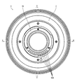
- FIG. 1 is a plan view showing an embodiment of an interchangeable lens to which the present invention is applied.
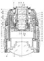
- Rear view of the interchangeable lens shown in FIG. FIG. 3 is a cross-sectional view taken along the line 3-3 when the zoom operation is performed to the wide end.
- FIG. 4 is a sectional view taken along line 4-4 of FIG. 2 when zooming to the wide end.
- FIG. 4 is a sectional view taken along line 4-4 of FIG. 2 when zooming to the telephoto end. 6-6 sectional view of FIG. 7-7 sectional view of FIG. Diagram showing the movement of each lens group when zoom operation is performed
- Sectional drawing which shows the support structure of a 3rd lens group movable holding frame and a 4th lens group movable holding frame.
- FIG. 4 is a diagram schematically illustrating a positional relationship between a third lens unit and a fourth lens unit at a wide end. The figure which shows typically the positional relationship of the 3rd lens group and the 4th lens group at a telephoto end.
- FIG. 2 is a block diagram mainly showing a first embodiment of a lens control unit of an interchangeable lens.
- FIG. 2 is a block diagram mainly showing a second embodiment of a lens control unit of an interchangeable lens.
- FIG. 7 is a block diagram mainly showing a third embodiment of a lens control unit of the interchangeable lens. The figure which showed the effect
- FIG. 9 is a block diagram mainly showing a fourth embodiment of the lens control unit of the interchangeable lens.
- 5 is a block diagram mainly showing a fifth embodiment of the lens control unit of the interchangeable lens.
- FIG. 1 is a plan view showing an embodiment of an interchangeable lens to which the present invention is applied.
- FIG. 2 is a rear view (view from the mount side) of the interchangeable lens shown in FIG.
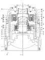
- FIG. 3 is a sectional view taken along line 3-3 in FIG. 2 when the zoom operation is performed to the wide end.
- FIG. 4 is a sectional view taken along line 4-4 in FIG. 2 when the zoom operation is performed to the wide end.
- FIG. 5 is a cross-sectional view taken along line 4-4 of FIG. 2 when the zoom operation is performed to the telephoto end.
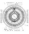
- FIG. 6 is a sectional view taken along line 6-6 of FIG.
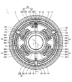
- FIG. 7 is a sectional view taken along the line 7-7 in FIG.
- the interchangeable lens 1 of the present embodiment is a so-called zoom lens, and the focal length changes continuously by a zoom operation.
- the interchangeable lens 1 includes a lens barrel main body 10 to which a lens is attached, and an exterior body 2 that covers the outer circumference of the lens barrel main body 10.
- the exterior body 2 has a cylindrical shape, accommodates the lens barrel main body 10 inside thereof, and covers the outer periphery of the lens barrel main body 10.
- the exterior body 2 includes a focus ring 3 as a focus operation member, a zoom ring 4 as a zoom operation member, and an aperture ring 5 as an aperture operation member.
- the focus of the interchangeable lens 1 is manually adjusted by rotating the focus ring 3. Further, by rotating the zoom ring 4, the focal length changes continuously within a predetermined range. By rotating the aperture ring 5, the aperture value (F value) is switched at predetermined steps.
- the lens barrel main body 10 is an example of a lens barrel.
- the lens barrel main body 10 has a fixed barrel 12 and a cam barrel 14.
- the cam cylinder 14 is fitted to the inner peripheral part of the fixed cylinder 12 and holds the inner peripheral part of the fixed cylinder 12 rotatably in the circumferential direction.
- the fixed cylinder 12 has a mount 16 at its rear end (the end on the image plane side).
- the mount 16 is constituted by a so-called bayonet mount.
- the cam cylinder 14 is connected to the zoom ring 4 via a connecting member (not shown). Therefore, when the zoom ring 4 is rotated, the cam barrel 14 also rotates in conjunction with the rotation.
- a plurality of lenses are arranged inside the fixed barrel 12. Specifically, a first lens group G1, a second lens group G2, a third lens group G3, a fourth lens group G4, and a fifth lens group that constitute a zoom lens are arranged in this order from the object side along the optical axis Z. G5 is arranged. Each lens group includes at least one lens.
- ⁇ ⁇ Aperture St is arranged inside fixed cylinder 12.
- the stop St is arranged between the first lens group G1 and the second lens group G2.
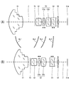
- FIG. 8 is a diagram illustrating a moving state of each lens group when a zoom operation is performed.
- (A) shows the lens arrangement at the wide end
- (B) shows the lens arrangement at the tele end.
- Curves indicated by reference signs AL1 to AL4 indicate the movement trajectories of the lens groups (zoom groups) that are moved by zoom operation.
- reference symbol AL1 denotes a movement locus of the first lens group G1
- reference sign AL2 denotes a movement locus of the second lens group G2
- reference sign AL3 denotes a movement locus of the third lens group G3
- reference sign AL4 denotes a movement locus of the fourth lens group G4.
- the moving locus is shown.
- the first lens group G1 to the fourth lens group G4 are lens groups that move with respect to the image plane Sim by a zoom operation.
- the fifth lens group G5 is a lens group fixed to the image plane Sim by a zoom operation.
- the stop St moves integrally with the second lens group G2.
- the third lens group G3 is composed of a third lens group front group G3a and a third lens group rear group G3b.
- the front third lens group G3a is a lens group for correcting the curvature of field, and corrects the curvature of field by moving along the optical axis Z.
- the third lens group front group G3a is configured to be movable independently, independently of the other lens groups.
- the fourth lens group G4 is a lens group for focus adjustment, and adjusts the focus by moving along the optical axis Z. For this reason, the fourth lens group G4 is configured to be independently movable independently of the other lens groups.
- the movement of each lens group by the zoom operation is realized by the cam mechanism.
- the cam mechanism converts the rotation of the cam barrel 14 into a linear motion, and moves each lens group along the optical axis Z.
- the cam mechanism includes a fixed barrel 12 having a rectilinear groove, a cam barrel 14 having a cam groove, and a cam follower provided in a holding frame of each lens group. You.
- Each of the first to fourth lens groups G1 to G4 is moved by a cam mechanism along predetermined movement trajectories AL1 to AL4.
- the cam mechanism is an example of a unit driving unit.
- First lens group G1 is held by the first lens group holding frame 20, is disposed in the fixed barrel 12, and passes through the fixed barrel 12 along the optical axis Z. Supported movably in a direction parallel to
- the first lens group holding frame 20 is provided with three first lens group driving cam followers 32 on the outer peripheral portion thereof.
- the three first lens group driving cam followers 32 are arranged at equal intervals in the circumferential direction.
- Each of the first lens group driving cam followers 32 is fitted into the first lens group driving cam groove 14A provided in the cam barrel 14 and the first lens group driving rectilinear groove 12A provided in the fixed barrel 12, respectively. .
- the first lens group G1 is held in the fixed barrel 12.
- the cam barrel 14 is rotated by the zoom ring 4
- the first lens group G1 moves along the optical axis Z in the fixed barrel 12 by the action of the cam mechanism.
- Second lens group As shown in FIGS. 3, 4, and 5, the second lens group G2 is held by the second lens group holding frame 22, is disposed in the fixed barrel 12, and passes through the fixed barrel 12 along the optical axis Z. Supported movably in a direction parallel to
- the second lens group holding frame 22 is provided with three second lens group driving cam followers 34 on its outer peripheral portion.
- the three second lens group driving cam followers 34 are arranged at equal intervals in the circumferential direction.
- the second lens group driving cam followers 34 are fitted into the second lens group driving cam grooves 14B provided in the cam barrel 14 and the second lens group driving straight grooves 12B provided in the fixed barrel 12, respectively. .
- the second lens group G2 is held in the fixed barrel 12.
- the cam barrel 14 is rotated by the zoom ring 4
- the second lens group G2 moves along the optical axis Z in the fixed barrel 12 by the action of the cam mechanism.
- an aperture unit 30 that constitutes the aperture St is assembled to the second lens group holding frame 22.
- the stop St is disposed in the fixed barrel 12 and moves together with the second lens group G2.
- the third lens group G ⁇ b> 3 is held by the third lens group holding frame 24, is arranged in the fixed barrel 12, and moves inside the fixed barrel 12. It is movably supported in a direction parallel to the optical axis Z.
- the third lens group holding frame 24 includes a third lens group base holding frame 24A and a third lens group movable holding frame 24B held by the third lens group base holding frame 24A.
- the third lens group movable holding frame 24B is arranged in the third lens group base holding frame 24A, and is movably supported in the third lens group base holding frame 24A in a direction parallel to the optical axis Z.
- the front group G3a of the third lens group is held by the third lens group movable holding frame 24B.
- the third lens group rear group G3b is held by the third lens group base holding frame 24A.
- the third lens group base holding frame 24A is provided with three third lens group driving cam followers 36 on its outer peripheral portion.
- the three third lens group driving cam followers 36 are arranged at equal intervals in the circumferential direction.
- Each of the third lens group driving cam followers 36 is fitted into a third lens group driving cam groove 14C provided in the cam barrel 14 and a third lens group driving rectilinear groove 12C provided in the fixed barrel 12, respectively. .
- the third lens group base holding frame 24 ⁇ / b> A is held in the fixed barrel 12.
- the third lens group base holding frame 24A moves along the optical axis Z in the fixed barrel 12.
- first main shaft 48 and a first sub shaft 50 are provided in the third lens group base holding frame 24A.
- the first main shaft 48 and the first sub shaft 50 are respectively arranged along the optical axis Z (see FIG. 3). Further, the first main shaft 48 and the first sub shaft 50 are arranged at positions facing each other with the optical axis Z interposed therebetween (see FIG. 6). More specifically, they are arranged on a straight line passing through the optical axis Z in a cross section orthogonal to the optical axis Z.
- the third lens group movable holding frame 24B includes a first main guide portion 52 that slides along the first main shaft 48 and a first sub guide portion 54 that slides along the first sub shaft 50.
- the third lens group movable holding frame 24B is slidably supported by the first main shaft 48 and the first sub shaft 50 via the first main guide portion 52 and the first sub guide portion 54.
- FIG. 9 is a cross-sectional view showing a support structure of the third lens group movable holding frame and the fourth lens group movable holding frame.
- the first main guide portion 52 has a cylindrical shape, and has sliding portions 52A at both ends in the axial direction.
- the sliding portion 52A has an inner diameter corresponding to the outer diameter of the first main shaft 48.
- the sliding portions 52A at both ends slide along the first main shaft 48.
- the first sub-guide portion 54 has a U-shaped groove 54A at the tip.
- the first sub guide portion 54 slides along the first sub shaft 50 by fitting the first sub shaft 50 into the groove portion 54A.
- the first main guide portion 52 is slidably supported by the first main shaft 48, and the first sub guide portion 54 is slidably supported by the first sub shaft 50. Accordingly, the third lens group base holding frame 24A is movably supported along the optical axis Z.
- the third lens group movable holding frame 24B is moved along the optical axis Z in the third lens group base holding frame 24A by being driven by the third lens group front group drive actuator 56.
- the third lens group front group drive actuator 56 is an example of a first actuator.
- the front group G3a of the third lens group is an example of a first optical element.
- the third lens group front group drive actuator 56 which functions as a first movable unit for moving the first lens (third lens group front group G3a) constituting the zoom lens in the direction of the optical axis of the zoom lens, is moved. It is composed of a magnet type (movable magnet type) voice coil motor (Voice Coil Motor: VCM).
- the moving magnet type VCM is a type of VCM in which a magnet moves in a magnetic field generated by a yoke and a coil.
- the VCM is one of the electromagnetic actuators using electromagnetic force.
- a plurality of driving magnets (first magnets) 56A and a plurality of inner yokes 56B constituted by the moving magnet type VCM are arranged on the third lens group movable holding frame 24B which is a movable portion. Further, a driving coil 56C (first coil) and a plurality of outer yokes 56D that constitute a moving magnet type VCM are disposed on the third lens group base holding frame 24A that is a fixed portion.
- FIG. 10 is a cross-sectional view showing the mounting structure of the third lens group front group drive actuator.
- the driving coil 56C is wound around the outer periphery of the third lens group movable holding frame 24B, and is attached to the inner periphery of the third lens group base holding frame 24A.
- the third lens group movable holding frame 24B moves inside the driving coil 56C along the optical axis Z.
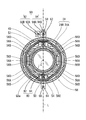
- the plurality of driving magnets 56A are arranged in two groups. Specifically, the two groups are arranged symmetrically with respect to a straight line L passing through the optical axis Z in a cross section orthogonal to the optical axis Z. On this straight line L, a first main shaft 48 and a first sub shaft 50 are arranged. Therefore, the two groups of the driving magnets 56 ⁇ / b> A are arranged symmetrically with respect to the straight line L passing through the first main shaft 48 and the first sub shaft 50.
- each group is provided with three driving magnets 56A.
- the driving magnets 56A of each group are arranged at equal intervals along the peripheral surface of the third lens group movable holding frame 24B.
- the plurality of inner yokes 56B are arranged corresponding to the driving magnets 56A.
- Each inner yoke 56B is integrated with the corresponding driving magnet 56A and attached to the third lens group movable holding frame 24B.
- a plurality of outer yokes 56D are arranged corresponding to a plurality of inner yokes 56B. Each outer yoke 56D is arranged to face the corresponding inner yoke 56B with the driving coil 56C interposed therebetween.
- the third lens group G3 is held in the fixed barrel 12.
- the third lens group G3 moves along the optical axis Z in the fixed barrel 12 by the action of the cam mechanism. That is, the third lens group front group G3a and the third lens group rear group G3b move in the fixed cylinder 12 along the optical axis Z as a unit.
- the third lens group front group drive actuator 56 is driven, the third lens group front group G3a moves alone along the optical axis Z.
- the third lens group front group drive actuator 56 moves the third lens group front group G3a by itself, thereby correcting the field curvature.
- the fourth lens group G ⁇ b> 4 is held by the fourth lens group holding frame 26, is disposed in the fixed barrel 12, and moves inside the fixed barrel 12. It is movably supported in a direction parallel to the optical axis Z.
- the fourth lens group holding frame 26 includes a fourth lens group base holding frame 26A and a fourth lens group movable holding frame 26B held by the fourth lens group base holding frame 26A.
- the fourth lens group movable holding frame 26B is arranged in the fourth lens group base holding frame 26A, and is movably supported in the fourth lens group base holding frame 26A in a direction parallel to the optical axis Z.
- the fourth lens group G4 is held by the fourth lens group movable holding frame 26B.
- the fourth lens group base holding frame 26A is provided with three fourth lens group driving cam followers 38 on the outer peripheral portion thereof.
- the three fourth lens group driving cam followers 38 are arranged at equal intervals in the circumferential direction.
- Each of the fourth lens group driving cam followers 38 is fitted into the fourth lens group driving cam groove 14D provided in the cam barrel 14 and the fourth lens group driving straight groove 12D provided in the fixed barrel 12, respectively. .
- the fourth lens group base holding frame 26A is held in the fixed barrel 12.
- the fourth lens group base holding frame 26A moves in the fixed barrel 12 along the optical axis Z.
- second main shaft 58 and a second sub shaft 60 are provided in the fourth lens group base holding frame 26A.
- the second main shaft 58 and the second sub shaft 60 are respectively arranged along the optical axis Z (see FIG. 3). Further, the second main shaft 58 and the second sub shaft 60 are arranged at positions facing each other with the optical axis Z interposed therebetween (see FIG. 7). Further, the second main shaft 58 is arranged at the same position as the first main shaft 48 in the circumferential direction of a circle centered on the optical axis Z. Accordingly, the second main shaft 58 and the second sub shaft 60 are arranged on the same straight line as the first main shaft 48 and the first sub shaft 50 in a cross section orthogonal to the optical axis Z.
- the term “identical” includes a range recognized as being substantially identical.
- the fourth lens group movable holding frame 26 ⁇ / b> B includes a second main guide portion 62 that slides along the second main shaft 58 and a second sub guide portion 64 that slides along the second sub shaft 60.
- the fourth lens group movable holding frame 26B is slidably supported by the second main shaft 58 and the second sub shaft 60 via the second main guide portion 62 and the second sub guide portion 64.
- the second main guide portion 62 has a cylindrical shape and has sliding portions 62A at both ends in the axial direction.
- the sliding portion 62A has an inner diameter corresponding to the outer diameter of the second main shaft 58.
- the sliding portions 62A at both ends of the second main guide portion 62 slide along the second main shaft 58.
- the second sub-guide portion 64 has a U-shaped groove 64A at the tip.
- the groove portion 64 ⁇ / b> A of the second sub guide portion 64 slides along the second sub shaft 60.
- the fourth lens group movable holding frame 26B In the fourth lens group movable holding frame 26B, the second main guide portion 62 is slidably supported by the second main shaft 58, and the second sub guide portion 64 is slidably supported by the second sub shaft 60. Thereby, the fourth lens group base holding frame 26A is movably supported along the optical axis Z.
- the fourth lens group movable holding frame 26B is driven by a plurality of fourth lens group drive actuators 68.
- the fourth lens group drive actuator 68 is an example of a second actuator.
- the fourth lens group G4 is an example of a second optical element.
- the fourth lens group drive actuator 68 which functions as a second movable unit for moving the second lens (the fourth lens group G4) constituting the zoom lens in the direction of the optical axis of the zoom lens is a moving coil type (movable coil type). It is composed of a voice coil motor (VCM) 68 of a coil type).
- VCM voice coil motor
- the moving coil type VCM is a type of VCM in which only the coil moves in a magnetic field generated by a magnet (permanent magnet). As described above, the VCM is one of the electromagnetic actuators using electromagnetic force.
- FIG. 11 is a sectional view showing a mounting structure of the fourth lens group drive actuator.
- the plurality of fourth lens group drive actuators 68 are divided into two groups and arranged. Specifically, the two groups are arranged symmetrically with respect to a straight line L passing through the optical axis Z in a cross section orthogonal to the optical axis Z.
- the second main shaft 58 and the second sub shaft 60 are arranged on the straight line L. Therefore, the two groups are arranged symmetrically with respect to the straight line L passing through the second main axis 58 and the second auxiliary axis 60.
- each group includes two fourth lens group drive actuators 68.
- the two fourth lens group drive actuators 68 are arranged at predetermined intervals along the peripheral surface of the fourth lens group movable holding frame 26B.
- Each fourth lens group drive actuator 68 includes a drive coil (second coil) 68A, a drive magnet (second magnet) 68B, an inner yoke 68C, and an outer yoke 68D.
- the driving coil 68A of each fourth lens group drive actuator 68 is disposed on the fourth lens group movable holding frame 26B which is a movable part.
- the fourth lens group movable holding frame 26B has a coil holding section 70 on the outer periphery thereof, and the coil holding section 70 holds a driving coil 68A of each fourth lens group drive actuator 68.
- each fourth lens group drive actuator 68 is arranged to face each other with the drive coil 68A interposed therebetween.
- the inner yoke 68C and the outer yoke 68D are integrally formed.
- the inner yoke 68C and the outer yoke 68D, which are integrally formed, are arranged at predetermined positions with the outer yoke 68D being held by the inner peripheral portion of the fourth lens group base holding frame 26A, which is a fixed portion.
- the drive magnet 68B of each fourth lens group drive actuator 68 is attached to the inside of the outer yoke 56D and is arranged at a predetermined position.
- the drive magnet 68B of each fourth lens group drive actuator 68 is an example of a plurality of second drive magnets.
- the fourth lens group G4 is held in the fixed barrel 12. Further, when the cam barrel 14 is rotated by the zoom ring 4, the fourth lens group G4 moves along the optical axis Z in the fixed barrel 12 by the action of the cam mechanism. Further, when the fourth lens group drive actuator 68 is driven, the fourth lens group G4 moves alone along the optical axis Z. By moving the fourth lens group G4 by itself by the fourth lens group drive actuator 68, focus adjustment is performed.
- ⁇ 5th lens group >> As shown in FIGS. 3, 4, and 5, the fifth lens group G ⁇ b> 5 is held in the fifth lens group holding frame 28 and arranged in the fixed barrel 12.
- Position detection of third lens group front group G3a and fourth lens group G4 >> The front group G3a and the fourth lens group G4 of the third lens group can move independently of the other lens groups. Therefore, the positions of the third lens group front group G3a and the fourth lens group G4 are separately detected.
- the position of the third lens group front group G3a is detected by a third lens group front group position detector (hereinafter, referred to as a “movable part position detector”) 80, and the fourth lens group G4 is a fourth lens group.
- the position is detected by the position detector 90.
- the movable section position detector 80 detects the position of the third lens group movable holding frame 24B within the third lens group base holding frame 24A, and detects the position of the third lens group front group G3a. More specifically, the position of the third lens group movable holding frame 24B with respect to a reference position set in the third lens group base holding frame 24A is detected, and the position of the third lens group front group G3a with respect to the reference position. Is detected.
- the movable part position detector 80 includes a position detecting magnet 82 provided in the third lens group movable holding frame 24B, and a position detector that detects the position of the position detecting magnet 82. 84.
- the position detector 84 is configured by a Hall sensor that is a magnetic sensor.
- the position detector 84 composed of a Hall sensor detects a magnetic field that changes in accordance with the position of the position detecting magnet 82, and outputs a signal proportional to the magnitude of the detected magnetic field as a position signal.
- the position detector 84 is provided in the third lens group base holding frame 24A. As shown in FIGS. 6 and 10, the position detector 84 is disposed at the installation position of the first sub shaft 50 in a cross section orthogonal to the optical axis Z. More specifically, they are arranged on a straight line L passing through the optical axis Z and the first sub-axis 50. The position detector 84 is disposed behind the first sub-axis 50 (on the image plane side) in a cross section parallel to the optical axis Z, as shown in FIGS.
- the position detecting magnet 82 is provided on the third lens group movable holding frame 24B.
- the position detecting magnet 82 is arranged close to the position detector 84.
- the first sub guide portion 54 is disposed at the installation position, and faces the position detector 84 with a predetermined gap. Placed.
- the position detecting magnet 82 and the position detector 84 are both arranged on a straight line L passing through the optical axis Z and the first sub-axis 50 in a cross section orthogonal to the optical axis Z.
- the position of the position detecting magnet 82 provided in the third lens group movable holding frame 24B is detected by the position detector 84.
- the position of G3a is detected.
- the fourth lens group position detector 90 detects the position of the fourth lens group movable holding frame 26B within the fourth lens group base holding frame 26A, and detects the position of the fourth lens group G4. More specifically, the position of the fourth lens group movable holding frame 26B with respect to the origin position set in the fourth lens group base holding frame 26A is detected, and the position of the fourth lens group G4 with respect to the origin position is detected. I do.
- the fourth lens group position detector 90 is an example of a second optical element position detector.
- the fourth lens group position detector 90 includes an origin position detector 92 that detects that the fourth lens group G4 is located at the origin position, a displacement amount detector 94 that detects a displacement amount of the fourth lens group G4, It consists of.
- the fourth lens group position detector 90 detects that the fourth lens group G4 is located at the origin position with the origin position detector 92, and detects the amount of displacement from the origin position with the displacement amount detector 94. The position of the four lens group G4 is detected.
- the origin position detector 92 includes a light shielding plate 92A and a photo interrupter 92B.
- the light blocking plate 92A is provided on the first main guide portion 52, and the photo interrupter 92B is provided on the fourth lens group base holding frame 26A.
- the origin position detector 92 detects that the fourth lens group G4 is located at the origin position by detecting the light shielding plate 92A by the photo interrupter 92B (the fourth lens group is detected by detecting the light shielding by the light shielding plate 92A).
- the light shielding plate 92A and the photo interrupter 92B are installed such that the light shielding plate 92A is detected at the timing when the fourth lens group G4 is located at the origin position (at the timing when the fourth lens group G4 is located at the origin position).
- the light shielding plate 92A is installed so as to shield the photo interrupter 92B from light.
- the displacement detector 94 includes a magnetic scale 94A and an MR sensor (Magneto Resistive Sensor) detecting the N pole and the S pole of the magnetic scale 94A. 94B.
- the MR sensor 94B is one of the magnetic sensors.
- the magnetic scale 94A has a bar shape, and has a structure in which N poles and S poles are magnetized at a constant pitch along the longitudinal direction.
- the magnetic scale 94A is provided on the second main guide portion 62, and is arranged along the moving direction of the fourth lens group G4. That is, they are arranged along the optical axis Z.
- the MR sensor 94B is provided in the fourth lens group base holding frame 26A.
- the MR sensor 94B is arranged close to the magnetic scale 94A. More specifically, as shown in FIG. 11, in a cross section orthogonal to the optical axis Z, it is arranged at the installation position of the second main guide portion 62, and is arranged to face the magnetic scale 94A with a predetermined gap. You.
- the magnetic scale 94A and the MR sensor 94B are both arranged on a straight line L passing through the optical axis Z and the second main axis 58 in a cross section orthogonal to the optical axis Z.
- the light blocking plate 92A provided in the second main guide portion 62 is detected by the photo interrupter 92B, so that the fourth lens group G4 is located at the origin position. Is detected.
- the displacement of the second main guide portion 62 is detected by the MR sensor 94B via the magnetic scale 94A, whereby the displacement of the fourth lens group G4 is detected.
- the photointerrupter 92B detects that the fourth lens group G4 is located at the origin position, and the MR sensor 94B detects the amount of displacement from the origin position, thereby detecting the position of the fourth lens group G4 with respect to the origin position. .
- the position detector 84 is disposed at the position of the first sub-axis 50 in a cross section orthogonal to the optical axis Z (see FIG. 10).
- the MR sensor 94B is disposed at the position of the second main guide portion 62 in a cross section orthogonal to the optical axis Z.
- the position of the second main guide portion 62 is the position of the second main shaft 58 (see FIG. 11).
- the first main axis 48 and the first sub-axis 50 and the second main axis 58 and the second sub-axis 60 are arranged on a straight line L passing through the optical axis Z in a cross section orthogonal to the optical axis Z. Therefore, the position detector 84 and the MR sensor 94B are arranged on a straight line L passing through the optical axis Z in a cross section orthogonal to the optical axis Z.
- the third lens group front group drive actuator 56 that drives the third lens group front group G3a includes a plurality of driving magnets 56A, a plurality of inner yokes 56B, and a plurality of outer yokes 56D, which are constituent elements thereof. In a cross section orthogonal to Z, they are arranged symmetrically with respect to a straight line L passing through the optical axis Z (see FIG. 10). That is, the elements constituting the magnetic body are arranged symmetrically with respect to a straight line L passing through the optical axis Z in a cross section orthogonal to the optical axis Z.
- the plurality of fourth lens group drive actuators 68 that drive the fourth lens group G4 are symmetrically arranged with respect to a straight line L passing through the optical axis Z in a cross section orthogonal to the optical axis Z (see FIG. 10). ). Also in this case, the elements constituting the magnetic body are arranged symmetrically with respect to a straight line L passing through the optical axis Z in a cross section orthogonal to the optical axis Z.
- the elements constituting the magnetic body are symmetrically disposed with respect to the position detector 84 and the MR sensor 94B in a cross section orthogonal to the optical axis Z.
- the influence of each magnetic sensor on each sensor can be made uniform, and more accurate detection can be performed.
- the first main shaft 48 and the first sub shaft 50 are arranged on the inner diameter side than the second main shaft 58 and the second sub shaft 60.
- the lengths of the first main shaft 48 and the second main shaft 58 can be increased, the lengths of the first main guide portion 52 and the second main guide portion 62 can be increased, and the third lens group front group G3a and the fourth lens Group G4 can be stably supported.
- the positional relationship between the position detector 84 which is a Hall sensor, and the fourth lens group drive actuator 68 changes by zooming. Therefore, the output of the position detector 84 is corrected according to the change in the positional relationship due to the zoom. This will be described in detail later.
- FIG. 12 is a block diagram illustrating an electrical configuration of the interchangeable lens.
- the interchangeable lens 1 includes a third lens group front group driving unit 110 that drives the third lens group front group G3a, a movable unit position detector 80 that detects the position of the third lens group front group G3a, and a fourth lens group G4.
- Fourth lens group drive section 112 to be driven fourth lens group position detector 90 for detecting the position of fourth lens group G4, aperture drive section 114 for driving aperture St, temperature detector for detecting the temperature inside the interchangeable lens 116, a focus operation detector 118 for detecting a focus operation, a zoom position detector 120 for detecting a zoom position, an aperture setting detector 122 for detecting an aperture operation, and a lens control unit 100 for integrally controlling the overall operation of the interchangeable lens 1. Is provided.
- the lens control unit 100 includes, for example, a CPU (Central Processing Unit) and a memory in which a lens control program and the like are stored, and performs overall control of each unit of the interchangeable lens 1 according to the lens control program.
- a CPU Central Processing Unit
- a memory in which a lens control program and the like are stored, and performs overall control of each unit of the interchangeable lens 1 according to the lens control program.
- the third lens group front group drive section 110 includes the third lens group front group drive actuator 56 and its drive circuit.
- the third lens group front group drive section 110 drives the third lens group front group drive actuator 56 in response to a command from the lens control section 100, and moves the third lens group front group G3a along the optical axis Z. Let it.
- the movable portion position detector 80 includes a position detector 84, and the position detector 84 detects the position of the position detecting magnet 82 provided on the third lens group movable holding frame 24B, and the position detector 84 detects the position of the third lens group.
- the position of the group G3a is detected.
- the position here is a position with respect to a reference position set in the third lens group base holding frame 24A.
- a position detector 84 composed of a Hall sensor detects a magnetic field that changes in accordance with the position of the position detecting magnet 82, and outputs a signal proportional to the magnitude of the detected magnetic field to the position signal of the third front lens group G3a. Is output to the lens control unit 100.
- the lens controller 100 processes a signal output from the position detector 84 to detect the position of the third front lens group G3a. At this time, processing is performed in consideration of the positional relationship between the position detector 84 and the fourth lens group drive actuator 68 to detect the position of the third lens group front group G3a.
- the fourth lens group drive section 112 includes a plurality of fourth lens group drive actuators 68 and a drive circuit therefor.
- the fourth lens group drive section 112 drives each fourth lens group drive actuator 68 in response to a command from the lens control section 100 to move the fourth lens group G4 along the optical axis Z.
- the fourth lens group position detector 90 includes an origin position detector 92 and a displacement detector 94.
- the origin position detector 92 includes a photo interrupter 92B, and detects that the fourth lens group G4 is located at the origin position.
- the displacement detector 94 includes an MR sensor 94B and detects the displacement of the fourth lens group G4.
- the origin position detector 92 detects that the fourth lens group G4 is located at the origin position, and the displacement amount detector 94 detects the amount of displacement from the origin position, thereby detecting the position of the fourth lens group G4.
- the aperture driving unit 114 includes an aperture driving actuator (not shown) for driving the aperture St, and a driving circuit therefor.
- the aperture drive actuator is formed of, for example, a step motor.
- the aperture driving unit 114 drives an aperture driving actuator in accordance with a command from the lens control unit 100 to expand and contract the aperture St.
- the temperature detector 116 has a temperature sensor (not shown), and detects the temperature inside the interchangeable lens by the temperature sensor.
- the temperature sensor is provided in the aperture unit 30, for example.
- the temperature detector 116 outputs information on the temperature inside the interchangeable lens detected by the temperature sensor to the lens control unit 100.
- the focus operation detector 118 detects a rotation operation amount of the focus ring 3 and outputs the detection result to the lens control unit 100.
- the lens control unit 100 detects a focus operation amount based on an output from the focus operation detector 118.
- the zoom position detector 120 detects the set position of the zoom ring 4 and outputs the detection result to the lens control unit 100.
- the lens control unit 100 detects the zoom position (set value of the focal length) based on the output from the zoom position detector 120.
- the aperture setting detector 122 detects the set position of the aperture ring 5 and outputs the detection result to the lens control unit 100.
- the lens controller 100 detects a set aperture value (F value) based on an output from the aperture setting detector 122.
- the settable aperture value includes auto, and when auto is selected, the aperture value is set based on an instruction from the camera body.
- the lens control unit 100 controls the operation of each unit based on the operation of the focus ring 3, the zoom ring 4, and the aperture ring 5. Specifically, when the manual focus is set, the fourth lens group drive actuator 68 is driven to move the fourth lens group G4 based on the rotation operation amount of the focus ring 3. At this time, the fourth lens group G4 is moved based on the position of the fourth lens group G4 detected by the fourth lens group position detector 90.
- the third lens group front group drive actuator 56 and the fourth lens group drive actuator 68 are driven based on the zoom position changed by the operation of the zoom ring 4, and the third lens group front group G3a and the fourth lens group G4 Is moved to a predetermined position.
- the third lens group front group G3a is moved to a predetermined position based on the position of the third lens group front group G3a detected by the movable part position detector 80.
- the fourth lens group G4 is moved to a predetermined position based on the position of the fourth lens group G4 detected by the fourth lens group position detector 90.
- the aperture driving unit 114 is driven to operate the aperture St.
- the lens control unit 100 controls the operation of each unit according to a command from a camera to which the interchangeable lens 1 is attached.
- the fourth lens group drive actuator 68 is driven based on autofocus information from the camera to move the fourth lens group G4 to a predetermined position.
- the aperture driving unit 114 is driven based on the aperture setting information from the camera to operate the aperture St.
- the lens control unit 100 communicates with the camera control unit 131 of the camera, and receives a drive command for each unit from the camera control unit 131. Further, the camera control unit 131 transmits zoom setting information, aperture setting information, focus position information, and the like. Communication between the lens control unit 100 and the camera control unit 131 is performed via a terminal 16A provided on the mount 16 (see FIG. 2).
- the lens controller 100 drives the third lens group front group drive actuator 56 based on the temperature detected by the temperature sensor to move the third lens group front group G3a to a predetermined position. Thereby, the field curvature caused by the temperature change is corrected.
- the lens control unit 100 is composed of, for example, a computer having a CPU (Central Processing Unit), a ROM (Read Only Memory), and a RAM (Random Access Memory), and executes a predetermined program. And implement various control functions.
- a computer having a CPU (Central Processing Unit), a ROM (Read Only Memory), and a RAM (Random Access Memory), and executes a predetermined program. And implement various control functions.
- CPU Central Processing Unit
- ROM Read Only Memory
- RAM Random Access Memory
- FIG. 13 is a diagram schematically showing the positional relationship between the third lens unit and the fourth lens unit at the wide end
- FIG. 14 is a diagram showing the positional relationship between the third lens unit and the fourth lens unit at the telephoto end. It is a figure which shows typically.
- the third lens group G3 and the fourth lens group G4 are adjacent to each other.
- the third lens group G3 and the fourth lens group G4 are both lens groups that are moved by a zoom operation. However, the amounts of movement by zoom are different from each other. Therefore, the relative positional relationship between the third lens group G3 and the fourth lens group G4 is changed by the zoom operation. Specifically, the position changes gradually from the wide end to the tele end (see FIG. 8). Therefore, the third lens group G3 and the fourth lens group G4 are closest to each other at the wide end (see FIG. 13), and are farthest apart at the telephoto end (see FIG. 14).
- the lens control unit 100 functions as a relative position acquisition unit that acquires a relative position between the third lens group movable holding frame 24B and the fourth lens group movable holding frame 26B based on the output from the zoom position detector 120.
- the driving magnet 56A and another magnetic body in this example, the yoke having the driving magnet 68B of the fourth lens group movable holding frame 26B) (The inner yoke 68C and the outer yoke 68D)), and if the attractive force or the repulsive force fluctuates particularly in accordance with the relative position between them, it may interfere with high-precision drive control.
- the drive control can be performed with high accuracy even if it receives a magnetic force from another magnetic body.
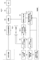
- FIG. 15 is a block diagram mainly showing a first embodiment of a lens controller of the interchangeable lens, and particularly shows a controller that drives and controls a third lens group front group drive actuator (hereinafter, referred to as “VCM”) 56. ing.
- VCM third lens group front group drive actuator
- a zoom position detection signal from the zoom position detector 120 is added to the movable portion position command device 123.
- a position command value indicating a target position for correcting field curvature is output by a front group of three lens groups (hereinafter, referred to as “first lens”) G3a.
- the position command value from the movable part position command device 123 is applied to the control unit 100-1.
- the control unit 100-1 mainly includes an adder 124 functioning as a first calculation unit, a position control calculation unit 130 and a parameter selection unit 140-1 functioning as a second calculation unit, and a driver 150. I have.
- the positive input of the adder 124 is added with a position command value from the movable part position commander 123, and the negative input of the adder 124 is a movable input indicating the current position of the first lens G3a from the movable part position detector 80.
- the adder 124 calculates a deviation (first operation amount) for position control of the VCM 56 by adding these two inputs, and outputs a deviation signal indicating the deviation to the position. Output to the control calculation unit 130.
- the parameter selection unit 140-1 includes a storage unit 142 that stores a position control calculation parameter group corresponding to the zoom position of the zoom lens, and selects a position control calculation parameter corresponding to the zoom position from the position control calculation parameter group. And outputs it to the position control calculation unit 130.
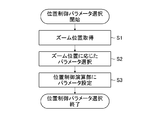
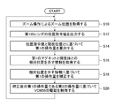
- FIG. 16 is a flowchart showing a procedure for selecting a position control calculation parameter.
- the parameter selection unit 140-1 acquires the zoom position from the zoom position detector 120 (step S1), and stores the position control calculation parameter corresponding to the acquired zoom position in the storage unit 142.
- a position control calculation parameter corresponding to the zoom position is selected from among the group of position control calculation parameters (step S2).
- the selected position control calculation parameter is output to the position control calculation unit 130, and the position control calculation parameter in the position control calculation unit 130 is set (step S3).
- the parameter selection unit 140-1 repeatedly executes steps S1 to S3, and sequentially updates the position control calculation parameters in the position control calculation unit 130 according to the zoom position.
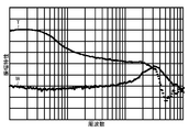
- FIGS. 17 and 18 are diagrams showing Bode diagrams of the amplitude characteristics and the phase characteristics of the VCM 56, respectively.
- T indicates drive characteristics when the zoom position is at the telephoto end
- W indicates drive characteristics when the zoom position is at the wide end.
- the drive characteristics of the VCM 56 differ depending on the zoom position, and the optimal position control calculation parameters at each zoom position differ.
- the position control calculation unit 130 generates a second operation amount (command value indicating magnetic force) for reducing the deviation in accordance with the deviation signal (first operation amount) input from the adder 124.
- the second operation amount is calculated (corrected) by switching the position control calculation parameter according to the zoom position input from the parameter selection unit 140-1.
- the driver 150 causes a current corresponding to the second operation amount (command value) input from the position control calculation unit 130 to flow through the VCM 56 (the driving coil 56C thereof), and the VCM 56 moves the first lens G3a, which is a movable unit, to the target position. Move to
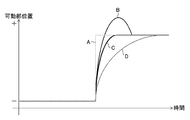
- FIG. 19 is a waveform diagram showing a response characteristic of the first lens G3a to the step-like target command value A.
- a waveform B shows a response when a magnetic force (attraction) in the positive direction acts on the driving magnet 56A of the VCM 56
- a waveform C shows a response when no magnetic force acts
- a waveform D Indicates a response when a negative magnetic force (repulsive force) acts.
- good driving performance for example, the characteristic shown in waveform C
- the optimal position control calculation parameter for example, the characteristic shown in waveform C
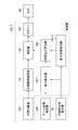
- FIG. 20 is a block diagram mainly showing a second embodiment of the lens control unit of the interchangeable lens, and particularly shows a control unit for driving and controlling the VCM 56.
- the same parts as those in the first embodiment shown in FIG. 15 are denoted by the same reference numerals, and detailed description thereof will be omitted.
- a control unit 100-2 of the second embodiment shown in FIG. 20 differs from the parameter selection unit 140-1 of the first embodiment in the parameter selection unit 140-2.
- a zoom position detection signal indicating the zoom position is added to the parameter selection unit 140-2 from the zoom position detector 120, and the movable unit position indicating the current position of the first lens G3a from the movable unit position detector 80.
- a detection signal has been added.
- the parameter selection unit 140-2 functioning as a relative position information acquisition unit, based on the zoom position detection signal and the movable unit position detection signal, selects the zoom position from the position control calculation parameter group stored in the storage unit 142. And a position control calculation parameter corresponding to the position of the movable part.
- the relative position between the driving magnet 56A of the VCM 56 and the other magnetic material is shifted from the current zoom position as in the first embodiment.
- the current position of the first lens G3a is also obtained in addition to the current zoom position, more accurate relative position information can be obtained.
- FIG. 21 is a block diagram mainly showing a third embodiment of the lens control unit of the interchangeable lens, and particularly shows a control unit which drives and controls the VCM 56.
- the same parts as those in the first embodiment shown in FIG. 15 are denoted by the same reference numerals, and detailed description thereof will be omitted.
- an adder 132 is provided between a position control calculation unit 130 and a driver 150, and a magnetic force (attractive force) applied as a disturbance by the adder 132 will be described later. And repulsive forces).
- a zoom position detection signal indicating the zoom position is added to the magnetic force calculation unit 160-1 from the zoom position detector 120, and a movable position indicating the current position of the first lens G3a is transmitted from the movable unit position detector 80.
- a part position detection signal is added.
- the magnetic force calculation unit 160-1 determines the driving magnet 56A of the VCM 56 and another magnetic body (the driving magnet 68B of the fourth lens group movable holding frame 26B) based on the zoom position detection signal and the movable unit position detection signal. Relative to the yoke), and calculate the magnetic force from another magnetic material that affects the driving magnet 56A.
- the magnetic force exerted on the driving magnet 56A from another magnetic body is small when the distance between them is large, and large when the distance between them is short.
- the magnetic force from another magnetic material that affects the driving magnet 56A is measured in advance according to the zoom position and the movable portion position (relative position), and a table or a calculation formula based on the measurement result is obtained, and the zooming is performed.
- the corresponding magnetic force can be read from the table based on the position and the movable portion position, or the magnetic force can be calculated by a calculation formula.
- the thrust constant calculation unit 170-1 receives a movable part position detection signal indicating the current position of the first lens G3a from the movable part position detector 80.
- a thrust constant (magnitude of thrust generated per unit current flowing through the driving coil 56C) corresponding to the current position of the lens G3a (that is, the position of the driving magnet 56A) is calculated.
- the thrust constant a value corresponding to the position of the driving magnet 56A determined by the VCM 56 can be used.
- the signal indicating the magnetic force calculated by the magnetic force calculation unit 160-1 and the signal indicating the thrust constant calculated by the thrust constant calculation unit 170-1 are added to the cancellation output calculation unit 180, and the cancellation output calculation unit 180-1
- the unit 180 calculates a canceling output (current value) for canceling a magnetic force from another magnetic material that affects the driving magnet 56A based on these input signals.
- the position control calculation unit 130 receives a deviation signal (first operation amount) indicating a position deviation 125 (a deviation between the position command value and the current position of the first lens G3a), and performs a second operation from the deviation signal.
- the amount (command value indicating magnetic force) is calculated and output to the adder 132.
- the offset input (current value) calculated by the offset output calculation unit 180 is added to the other input of the adder 132, and the adder 132 adds the offset output to the second operation amount, The second operation amount is corrected.
- the second operation amount corrected by the adder 132 is output to the driver 150.
- the driver 150 adds the output 182 (current / voltage) corresponding to the second manipulated variable corrected by the adder 132 to the VCM 56.
- a current corresponding to the corrected second operation amount flows through the driving coil 56C of the VCM 56, and the first lens G3a, which is the movable portion, is not affected by the magnetic force acting as a disturbance (disturbance).
- Drive is controlled so that the magnetic force of
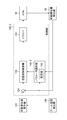
- FIG. 22 is a diagram schematically showing the operation of the third embodiment.
- each symbol is as follows.
- the output of the control unit matches the force F required for driving the target, and the target can be driven.
- the output G of the control unit is affected by the magnetic force H, and the resultant force I received by the movable unit is smaller than the output F required for target driving.
- the output K of the control unit is an output obtained by summing the force F required for driving the target and the output J for canceling the magnetic force (positive and negative are different from the magnetic force H).
- the output K of the control unit which is the sum of the force L required for the target drive and the output J for canceling the magnetic force, is smaller than the force L required for the target drive, but is affected by the magnetic force H.
- the resultant force I received by the movable portion matches the force L required for driving the target, and the target can be driven.
- the influence of the magnetic force, which is a disturbance, is apparently canceled, so that highly accurate drive control can be realized.
- FIG. 23 is a block diagram mainly showing a fourth embodiment of the lens control unit of the interchangeable lens, and particularly shows a control unit that drives and controls the VCM 56.
- the same parts as those in the third embodiment shown in FIG. 21 are denoted by the same reference numerals, and detailed description thereof will be omitted.
- the magnetic force calculation unit 160-2 and the thrust constant calculation unit 170-2 mainly perform the magnetic force calculation unit 160-1 and the thrust constant calculation of the third embodiment. This is different from the unit 170-1.
- the leakage magnetic flux of the driving magnet 56A of the VCM 56 changes depending on the temperature inside the interchangeable lens 1, and the magnetic force between the magnet and another magnetic body changes. For example, when the temperature becomes higher than the room temperature, the leakage magnetic flux decreases, and the magnetic force between the magnetic material and another magnetic material also decreases. On the other hand, when the temperature is lower than the room temperature, the leakage magnetic flux increases, and the magnetic force between the magnetic material and other magnetic materials also increases.
- the temperature detector 116 for detecting the temperature inside the interchangeable lens is provided, and the magnetic force calculation unit 160-2 and the thrust constant calculation unit 170-2 provide the temperature T obtained by the temperature detector 116.
- the magnetic force and the thrust constant are calculated (corrected) based on.
- the magnetic force calculation unit 160-2 calculates the magnetic force X obtained by correcting the magnetic force calculated under the condition of the normal temperature Tr by the temperature T using the following equation.
- ⁇ is a temperature coefficient for correcting magnetic force by temperature.
- the thrust constant calculation unit 170-2 calculates a thrust constant Y obtained by correcting the thrust constant calculated under the condition of the normal temperature Tr with the temperature T by the following equation.
- Equation 2 Thrust constant ⁇ ⁇ (T-Tr)
- ⁇ is a temperature coefficient for correcting the thrust constant by temperature.
- the canceling output calculation unit 180 is configured to control the driving magnet 56A based on the magnetic force X and the thrust constant Y calculated by the magnetic force calculation unit 160-2 and the thrust constant calculation unit 170-2, respectively. Calculate the cancellation output for canceling the magnetic force.
- FIG. 24 is a block diagram mainly showing a fifth embodiment of the lens controller of the interchangeable lens, and particularly shows a controller that drives and controls the VCM 56.
- the same parts as those in the fourth embodiment shown in FIG. 23 are denoted by the same reference numerals, and detailed description thereof will be omitted.
- the control unit 100-5 according to the fifth embodiment shown in FIG. 24 is different from the control unit 100-5 mainly in that a first offset processing unit 190, a second offset processing unit 192, and a parameter selection unit 140-3 are added. This is different from the fourth embodiment.
- a first offset processing unit 190 and a second offset processing unit 192 are provided to compensate for these individual differences.
- the offset of the zoom position corresponding to the individual difference of the interchangeable lens 1 is set in the first offset processing unit 190, and the first offset processing unit 190 sets the zoom position detected by the zoom position detector 120 to the zoom position.
- the offset for each individual is added and output to the magnetic force calculation unit 160-3.
- an offset of the movable section position corresponding to the individual difference of the interchangeable lens 1 is set, and the second offset processing section 192 is detected by the movable section position detector 80.
- An offset for each individual is added to the current position of the movable part (first lens G3a), which is output to the thrust constant calculation unit 170-3.
- the magnetic force calculation unit 160-3 and the thrust constant calculation unit 170-3 can calculate the magnetic force and the thrust constant without being affected by the individual difference of the interchangeable lens 1, and the offset output calculation unit 180 An offset output that compensates for the individual difference of the lens 1 can be calculated.
- the parameter selection unit 140-3 acquires the offsets set in the first offset processing unit 190 and the second offset processing unit 192, respectively, and switches the position control calculation parameter based on the acquired offsets.
- the second operation amount that compensates for the individual difference of the interchangeable lens 1 is calculated (corrected).
- the driving magnet 56A of the VCM 56 causes the inner yoke 68C and the outer yoke 68D of the moving coil type VCM 68 that moves the fourth lens group G4 in the optical axis direction of the zoom lens to be affected by magnetic force.
- the other magnetic material is not limited to this.
- a camera shake correction lens (second lens) is moved in a direction orthogonal to the optical axis direction of the zoom lens.
- the magnetic material included in the electromagnetic actuator may be another magnetic material.
- FIG. 25 is a flowchart showing an embodiment of the lens control method according to the present invention.
- the lens control method shown in FIG. 25 is applied to the interchangeable lens 1 (lens barrel) shown in FIGS. 1 to 14, and in particular, the third lens group front group G3a (movable part) by the lens control unit 100 shown in FIG. ) Is a drive control method according to the zoom position.
- the lens control unit 100 acquires a zoom position based on the output from the zoom position detector 120 (Step S10).
- the movable unit position command device 123 (FIG. 15) outputs a position command value indicating a target position for correcting the curvature of field by the first lens G3a according to the zoom position (step S12).
- the adder 124 calculates a deviation (first operation amount) for position control of the VCM 56 that drives the first lens G3a based on the position command value and the current position of the first lens G3a (Step S14). .
- the lens controller 100 acquires information indicating the relative position between the driving magnet (first magnet) 56A of the VCM 56 and another magnetic body based on the zoom position (Step S16).
- the lens controller 100 corrects the first operation amount calculated in step S14 based on the acquired information indicating the relative position (step S18).
- an attractive force or a repulsive force acts between the driving magnet 56A and another magnetic material, and the attractive force or the repulsive force fluctuates particularly in accordance with a relative position between the two.
- the first operation amount is corrected so as to cancel each other (step S18).
- a method of correcting the first operation amount a method of switching the position control calculation parameter used by the position control calculation unit 130 according to the zoom position as shown in FIG.
- the lens controller 100 controls the driving of the VCM 56 based on the second operation amount that is the corrected first operation amount (Step S20).
- the interchangeable lens (lens barrel) has been described.
- an imaging device having a lens barrel, an imaging device integrated with a lens, a digital video camera, or the like may be used.
- the present invention is also applicable to a mobile device having other functions (call function, communication function, other computer functions).
- ⁇ Other embodiments to which the present invention can be applied include, for example, mobile phones and smartphones having a camera function, PDAs (Personal Digital Assistants), and portable game machines.
- PDAs Personal Digital Assistants
- portable game machines Portable game machines
- FIG. 26 illustrates an appearance of a smartphone 500 which is an embodiment of the imaging device of the present invention.
- the smartphone 500 illustrated in FIG. 26 includes a flat housing 502, and a display input in which a display panel 521 as a display unit and an operation panel 522 as an input unit are integrated on one surface of the housing 502.
- a section 520 is provided.
- the housing 502 includes a speaker 531, a microphone 532, an operation unit 540, and a camera unit 541.
- the configuration of the housing 502 is not limited to this. For example, a configuration in which the display unit and the input unit are independent from each other, or a configuration including a folding structure and a slide mechanism may be employed.
- FIG. 27 is a block diagram showing a configuration of smartphone 500 shown in FIG.
- the main components of the smartphone include a wireless communication unit 510 that performs mobile wireless communication via a base station and a mobile communication network, a display input unit 520, a communication unit 530, and an operation unit 540.
- GPS Global Positioning System
- the wireless communication unit 510 performs wireless communication with a base station accommodated in a mobile communication network according to an instruction from the main control unit 501. Using this wireless communication, transmission and reception of various file data such as audio data and image data, e-mail data, and the like, and reception of Web data and streaming data are performed.
- the display input unit 520 displays images (still images and moving images), character information, and the like, visually transmits information to a user, and detects a user operation on the displayed information. It is a so-called touch panel, which includes a display panel 521 and an operation panel 522.
- the display panel 521 uses an LCD (Liquid Crystal Display), an OELD (Organic Electro-Luminescence Display), or the like as a display device.
- the operation panel 522 is a device that is mounted so that an image displayed on the display surface of the display panel 521 can be visually recognized, and detects one or a plurality of coordinates operated by a user's finger or a stylus. When such a device is operated by a user's finger or a stylus, a detection signal generated due to the operation is output to the main control unit 501. Next, the main control unit 501 detects an operation position (coordinate) on the display panel 521 based on the received detection signal.
- a display input unit 520 is integrally formed with a display panel 521 and an operation panel 522 of a smartphone 500 exemplified as an embodiment of the imaging apparatus of the present invention.
- 522 is arranged to completely cover the display panel 521.
- the operation panel 522 may have a function of detecting a user operation even in an area outside the display panel 521.
- the operation panel 522 includes a detection area (hereinafter, referred to as a display area) for a superimposed portion overlapping the display panel 521 and a detection area (hereinafter, a non-display area) for an outer edge portion not overlapping the display panel 521. ).
- the size of the display area and the size of the display panel 521 may completely match, but it is not always necessary to match them.
- the operation panel 522 may include two sensitive regions of an outer edge portion and an inner portion other than the outer edge portion. Further, the width of the outer edge portion is appropriately designed according to the size of the housing 502 and the like.
- a position detection method adopted in the operation panel 522 a matrix switch method, a resistive film method, a surface acoustic wave method, an infrared ray method, an electromagnetic induction method, a capacitance method, and the like can be mentioned, and any of these methods is adopted. You can also.
- the communication unit 530 includes a speaker 531 and a microphone 532, converts the user's voice input through the microphone 532 into voice data that can be processed by the main control unit 501, and outputs the voice data to the main control unit 501.
- the audio data received by the external input / output unit 510 or the external input / output unit 560 is decoded and output from the speaker 531.
- the speaker 531 and the microphone 532 can be mounted on the same surface as the surface on which the display input unit 520 is provided.
- the operation unit 540 is a hardware key using a key switch or the like, and receives an instruction from a user.
- the operation unit 540 is mounted on a side surface of the housing 502 of the smartphone 500, and is turned on when pressed with a finger or the like, and turned off due to a restoring force of a spring or the like when the finger is released. It is a push button type switch.
- the recording unit 550 includes a control program of the main control unit 501, control data, application software, address data corresponding to a communication partner's name and telephone number, transmitted and received e-mail data, Web data downloaded by Web browsing, and It stores downloaded content data and temporarily stores streaming data and the like.
- the recording unit 550 includes an internal storage unit 551 built in the smartphone and an external storage unit 562 having a removable external memory slot.
- the internal storage unit 551 and the external storage unit 552 constituting the recording unit 550 include a flash memory type (flash memory type), a hard disk type (hard disk type), a multimedia card micro type (multimedia card micro type), This is realized using a recording medium such as a card type memory (for example, Micro @ SD (registered trademark) memory), a RAM (Random Access Memory), and a ROM (Read Only Memory).
- flash memory type flash memory type
- hard disk type hard disk type
- multimedia card micro type multimedia card micro type
- a recording medium such as a card type memory (for example, Micro @ SD (registered trademark) memory), a RAM (Random Access Memory), and a ROM (Read Only Memory).
- the external input / output unit 560 serves as an interface with all external devices connected to the smartphone 500, and communicates with other external devices (for example, a universal serial bus (USB), IEEE 1394, or the like) or Network (for example, Internet, wireless LAN (Local Area Network), Bluetooth (registered trademark), RFID (Radio Frequency Identification), infrared communication (Infrared Data Association: IrDA) (registered trademark), UWB (Ultra Wideband) ( (Registered trademark), ZigBee (registered trademark), etc.).
- USB universal serial bus
- IEEE 1394 or the like
- Network for example, Internet, wireless LAN (Local Area Network), Bluetooth (registered trademark), RFID (Radio Frequency Identification), infrared communication (Infrared Data Association: IrDA) (registered trademark), UWB (Ultra Wideband) ( (Registered trademark), ZigBee (registered trademark), etc.).
- IrDA Infrared Data Association
- UWB User
- the external devices connected to the smartphone 500 include, for example, a wired / wireless headset, a wired / wireless external charger, a wired / wireless data port, a memory card (Memory @ card) connected via a card socket, and a SIM (Subscriber).
- a smartphone to be connected
- a personal computer to be wired / wirelessly connected
- a PDA to be wired / wirelessly connected
- the external input / output unit can transmit data transmitted from such an external device to each component inside the smartphone 500, or can transmit data inside the smartphone 500 to the external device.
- the GPS receiving unit 570 receives the GPS signals transmitted from the GPS satellites ST1 to STn according to the instruction of the main control unit 501, executes a positioning calculation process based on the received GPS signals, A position consisting of longitude and altitude is detected.
- the GPS receiving unit 570 can acquire position information from the wireless communication unit 510 or the external input / output unit 560 (for example, a wireless LAN), the GPS receiving unit 570 can also detect the position using the position information.
- the motion sensor unit 580 includes, for example, a three-axis acceleration sensor and a gyro sensor, and detects a physical movement of the smartphone 500 according to an instruction from the main control unit 501. By detecting the physical movement of the smartphone 500, the moving direction and the acceleration of the smartphone 500 are detected. This detection result is output to the main control unit 501.
- the power supply unit 590 supplies power stored in a battery (not shown) to each unit of the smartphone 500 in accordance with an instruction from the main control unit 501.
- the main control unit 501 includes a microprocessor, operates according to a control program and control data stored in the recording unit 550, and controls the components of the smartphone 500 in an integrated manner. Further, the main control unit 501 has a mobile communication control function and an application processing function for controlling each unit of the communication system in order to perform voice communication and data communication via the wireless communication unit 510.
- the application processing function is realized by the main control unit 501 operating according to the application software stored in the recording unit 550.
- the application processing functions include, for example, an infrared communication function for controlling the external input / output unit 560 to perform data communication with a counterpart device, an e-mail function for transmitting / receiving e-mail, a Web browsing function for browsing Web pages, and the present invention. , And an image processing function for performing HDR synthesis.
- the main control unit 501 also has an image processing function such as displaying a video on the display input unit 520 based on image data (still image or moving image data) such as received data or downloaded streaming data.
- the image processing function refers to a function in which the main control unit 501 decodes the image data, performs image processing on the decoding result, and displays an image on the display input unit 520.
- the main control unit 501 executes display control on the display panel 521 and operation detection control for detecting a user operation through the operation unit 540 and the operation panel 522.
- the main control unit 501 By executing the display control, the main control unit 501 displays an icon for starting application software and a software key such as a scroll bar, or displays a window for creating an e-mail.
- a software key such as a scroll bar
- the scroll bar is a software key for receiving an instruction to move a display portion of an image such as a large image that cannot be accommodated in the display area of the display panel 521.
- the main control unit 501 detects a user operation through the operation unit 540, receives an operation on an icon through the operation panel 522, and receives an input of a character string in an input field of a window, or scrolls. A request to scroll a display image through a bar is received.
- the main control unit 501 determines whether the operation position on the operation panel 522 is a superimposed portion (display region) overlapping the display panel 521 or an outer edge portion not overlapping the display panel 521 (non-display region). ) Is provided, and a touch panel control function for controlling the sensitive area of the operation panel 522 and the display position of the software key is provided.
- the main control unit 501 can also detect a gesture operation on the operation panel 522 and execute a preset function according to the detected gesture operation.
- the gesture operation is not a conventional simple touch operation but an operation of drawing a trajectory with a finger or the like, specifying a plurality of positions at the same time, or combining these to draw a trajectory for at least one from a plurality of positions. means.
- the camera unit 541 is a digital camera that electronically shoots using an image sensor such as a complementary metal oxide semiconductor (CMOS) or a charge-coupled device (CCD), and is a zoom lens similar to the interchangeable lens 1 (lens barrel) described above. It has. That is, the zoom lens of the camera unit 541 forms a zoom lens with a first movable unit (moving magnet type VCM) that moves the first lens forming the zoom lens in the direction of the optical axis of the zoom lens. There is provided a second movable unit (electromagnetic actuator) for moving the second lens in the direction of the optical axis of the zoom lens or in a direction orthogonal to the direction of the optical axis.
- CMOS complementary metal oxide semiconductor
- CCD charge-coupled device
- the camera unit 541 includes a first calculation unit that calculates a first operation amount for position control of the VCM based on the position command value of the first lens and the current position of the first lens;
- a relative position information acquisition unit configured to acquire information indicating a relative position between the first magnet and another magnetic body, to correct a first operation amount based on the acquired information indicating the relative position, and
- a control unit for controlling driving is provided.
- the camera unit 541 converts image data obtained by imaging into compressed image data such as JPEG (Joint Photographic coding Experts Group) under the control of the main control unit 501, and records the compressed image data in the recording unit 550 or external input / output. It can be output through the unit 560 or the wireless communication unit 510.
- the camera unit 541 is mounted on the same surface as the display input unit 520, but the mounting position of the camera unit 541 is not limited to this, and the camera unit 541 is mounted on the back of the display input unit 520.
- a plurality of camera units 541 may be mounted. When a plurality of camera units 541 are mounted, the camera unit 541 to be used for photographing can be switched to perform shooting independently, or shooting can be performed using a plurality of camera units 541 simultaneously.
- the camera unit 541 can be used for various functions of the smartphone 500.
- the image acquired by the camera unit 541 can be displayed on the display panel 521, and the image of the camera unit 541 can be used as one of the operation inputs of the operation panel 522.
- the GPS receiving section 570 detects the position, the position can be detected with reference to the image from the camera section 541.
- the optical axis direction of the camera unit 541 of the smartphone 500 is used without using the three-axis acceleration sensor or in combination with the three-axis acceleration sensor (gyro sensor). Can be determined, and the current use environment can also be determined.
- the image from the camera unit 541 can be used in the application software.
- position information obtained by the GPS receiving unit 570 to image data of a still image or a moving image may be converted into text information by performing audio-to-text conversion by the main control unit or the like), Posture information or the like acquired by the motion sensor unit 580 can be added and recorded in the recording unit 550, or output via the external input / output unit 560 or the wireless communication unit 510.
- a lens (first lens) for correcting field curvature is controlled by a moving magnet type VCM in accordance with a zoom position of a lens group included in a zoom lens.
- the lens to be controlled is not limited to this, and can be applied to any lens drive control as long as the lens is driven in the direction of the optical axis of the zoom lens by a moving magnet type VCM.
- the hardware structure of a processing unit (processing @ unit) that executes various processes of the lens control unit 100 of the interchangeable lens 1 includes the following various processors.
- the circuit configuration can be changed after manufacturing such as CPU (Central Processing Unit) and FPGA (Field Programmable Gate Array), which are general-purpose processors that execute software (programs) and function as various processing units.
- Special-purpose circuits such as programmable logic devices (Programmable Logic Devices: PLDs), ASICs (Application Specific Integrated Circuits), etc. It is.
- One processing unit may be configured by one of these various processors, or configured by two or more processors of the same type or different types (for example, a plurality of FPGAs or a combination of a CPU and an FPGA). You may. Further, a plurality of processing units may be configured by one processor. As an example in which a plurality of processing units are configured by one processor, first, as represented by a computer such as a client or a server, one processor is configured by a combination of one or more CPUs and software. There is a form in which a processor functions as a plurality of processing units.
- SoC System-on-Chip
- IC integrated circuit
- circuitry in which circuit elements such as semiconductor elements are combined.
- the present invention is a lens control program that is installed in a lens barrel or an imaging device (computer) to function as the lens barrel or the imaging device according to the present invention, and a recording in which the lens control program is recorded. Including media.
Landscapes
- Physics & Mathematics (AREA)
- General Physics & Mathematics (AREA)
- Engineering & Computer Science (AREA)
- Multimedia (AREA)
- Signal Processing (AREA)
- Optics & Photonics (AREA)
- Lens Barrels (AREA)
- Structure And Mechanism Of Cameras (AREA)
- Adjustment Of Camera Lenses (AREA)
- Studio Devices (AREA)
Abstract
ムービングマグネット方式のボイスコイルモータを使用してレンズを光軸の方向に移動させる場合に、磁力が変動しても高精度な駆動制御を行うことができるレンズ鏡胴、撮像装置、レンズ制御方法及びレンズ制御プログラムを提供する。レンズ鏡胴は、ズームレンズを構成する第1、第2のレンズを、ズームレンズの光軸の方向に移動させる第1、第2の可動ユニットを備える。第1の可動ユニットは、ムービングマグネット方式のボイスコイルモータであり、可動部に配設されたマグネットは、他の磁性体との相対位置に応じた磁力を受ける。制御部100-1は、第1のレンズの位置指令値と第1のレンズの現在位置とに基づいて演算される第1の可動ユニットの位置制御用の第1の操作量を、第1のマグネットと磁性体との相対位置を示す情報に基づいて補正し、第1の可動ユニットの駆動を制御する。
Description
本発明はレンズ鏡胴、撮像装置、レンズ制御方法及びレンズ制御プログラムに係り、特にレンズを光軸の方向に移動させる可動ユニットのアクチュエータとして、ムービングマグネット方式のボイスコイルモータを使用する場合に適用する技術に関する。
従来からレンズを移動させるアクチュエータとして、ボイスコイルモータが広く使用されている。
ボイスコイルモータには、可動部にコイルが配設され、固定部にマグネットが配設されたムービングコイル方式のボイスコイルモータと、可動部にマグネットが配設され、固定部にコイルが配設されたムービングマグネット方式のボイスコイルモータとがある。
ムービングコイル方式のボイスコイルモータは、可動部が移動しても可動部のマグネットと他の磁性体との間で引力や斥力が変動しないため、高精度な駆動制御を行うことができる利点があるが、ムービングマグネット方式のボイスコイルモータに比べて外径が大きくなるという問題がある。
一方、ムービングマグネット方式のボイスコイルモータは、可動部の移動に伴って可動部のマグネットと他の磁性体との間に発生する引力や斥力が変動し、高精度な駆動制御の障害になる場合があるが、ムービングコイル方式のボイスコイルモータに比べて外径を小さくすることができる利点がある。
特許文献1には、第1群と第2群との間にプリズムが配設された、第1群~第4群からなる屈曲光学系を有するズームレンズが記載されている。
第1群は、ムービングマグネット方式の2つのボイスコイルモータにより光軸と直交する方向に移動し、手振れなどの振動を起因とする像面上での像振れを軽減させるための、いわゆる防振機構を構成している。第2群及び第3群は、それぞれ2つのモータから送りネジを介して伝達される駆動力により光軸に沿って移動し、変倍動作を行う。
また、特許文献1には、「可動の第1レンズ枠上に永久磁石を支持したムービングマグネットタイプの電磁アクチュエータでは、高精度な駆動制御を行わせるために、永久磁石の磁界に対する外部の磁性体からの影響を排除することが求められる。」旨の記載がある(特許文献1の段落[0064])。
特許文献1に記載のズームレンズは屈曲光学系であり、ボイスコイルモータにより駆動される第1群の第1レンズ枠に保持されるマグネット(永久磁石)は、第1群の移動方向によっては、磁性体であるズーム駆動用のモータに近づいたり、遠ざかったりする。
特許文献1に記載の発明は、ムービングマグネット方式の2つのボイスコイルモータを、第1群の第2象限と第3象限に配置し、第1象限や第4象限に配置した場合に比べてモータ(磁性体)からの距離を大きくし、磁性体からの影響が及びにくくしている。
特許文献1に記載のズームレンズは、ムービングマグネット方式のボイスコイルモータにより第1群が移動するが、第1群は、光軸と直交する方向に移動して防振機構を構成するものであり、光軸方向に移動するレンズではない。
また、ムービングマグネット方式の2つのボイスコイルモータを、第1群の第2象限と第3象限に配置し、第1象限や第4象限に配置した場合に比べてモータ(磁性体)からの距離を大きくし、磁性体からの影響が及びにくくしているものの、外部のモータ(磁性体)の配置によっては、磁性体からの影響を低減することができず、ムービングマグネット方式のボイスコイルモータを高精度に駆動制御することができないという問題がある。
本発明は、このような事情に鑑みてなされたもので、ムービングマグネット方式のボイスコイルモータを使用してレンズを光軸の方向に移動させる場合に、磁力が変動しても高精度な駆動制御を行うことができるレンズ鏡胴、撮像装置、レンズ制御方法及びレンズ制御プログラムを提供することを目的とする。
本発明の一の態様に係るレンズ鏡胴は、ズームレンズを構成する第1のレンズを、ズームレンズの光軸の方向に移動させる第1の可動ユニットと、ズームレンズを構成する第2のレンズを、ズームレンズの光軸の方向又は光軸の方向と直交する方向に移動させる第2の可動ユニットと、第1の可動ユニットの駆動を制御する制御部と、を備え、第1の可動ユニットは、可動部に第1のマグネットが配設され、固定部に第1のコイルが配設されたムービングマグネット方式のボイスコイルモータであり、かつ第1のマグネットは、第1のマグネットと第2の可動ユニットに含まれる磁性体との相対位置に応じた磁力を磁性体から受け、制御部は、第1のレンズの位置指令値と第1のレンズの現在位置とに基づいて第1の可動ユニットの位置制御用の第1の操作量を演算する第1の演算部と、第1のマグネットと磁性体との相対位置を示す情報を取得する相対位置情報取得部とを備え、取得した相対位置を示す情報に基づいて第1の操作量を補正し、第1の可動ユニットの駆動を制御する。
第1の可動ユニットは、ムービングマグネット方式のボイスコイルモータであり、可動部に配設されたマグネットは、他の磁性体(第2の可動ユニットに含まれる磁性体)との相対位置に応じた磁力を磁性体から受ける。
本発明の一の態様によれば、第1のレンズの位置指令値と第1のレンズの現在位置とに基づいて演算される第1の可動ユニットの位置制御用の第1の操作量を、第1のマグネットと磁性体との相対位置を示す情報に基づいて第1の操作量を補正し、第1の可動ユニットの駆動を制御するため、他の磁性体から磁力を受けても高精度に駆動制御することができる。
本発明の他の態様に係るレンズ鏡胴において、制御部は、第1の操作量を補正する第2の操作量を演算し、第1のマグネットが磁性体から受ける磁力を打ち消す第2の演算部を備え、演算された第2の操作量に基づいて第1の可動ユニットの駆動を制御することが好ましい。
本発明の他の態様によれば、第1のマグネットが他の磁性体から受ける磁力(引力や斥力)を打ち消すように、第1の操作量を補正した第2の操作量を演算し、第2の操作量により第2の操作量に基づいて第1の可動ユニットの駆動を制御するようにしたため、良好な駆動特性を確保することができる。
本発明の更に他の態様に係るレンズ鏡胴において、相対位置情報取得部は、ズームレンズのズーム位置を取得し、第2の演算部は、取得したズーム位置に基づいて第1のマグネットが磁性体から受ける磁力を打ち消す出力を算出し、算出した出力により第1の操作量から第2の操作量を算出することが好ましい。
第1の可動ユニットは、ズームレンズのズーム位置に応じて移動するため、ズーム位置を取得することで、第1の可動ユニットの可動部に配設された第1のマグネットと他の磁性体との相対位置を示す情報を取得することができる。
本発明の更に他の態様に係るレンズ鏡胴において、相対位置情報取得部は、ズームレンズのズーム位置に、レンズ鏡胴の個体ごとのバラツキを示す第1のオフセットを追加し、第1のオフセットを追加したズーム位置を取得することが好ましい。
ズームレンズのズーム位置は、レンズ鏡胴の個体ごとにバラツキがあるため、ズームレンズのズーム位置に、個体ごとのバラツキを示す第1のオフセットを追加することで、個体ごとにバラツキのないズーム位置(精度の高い相対位置)を取得することができる。
本発明の更に他の態様に係るレンズ鏡胴において、相対位置情報取得部は、ズームレンズのズーム位置及び第1の可動ユニットの可動部の位置をそれぞれ取得し、第2の演算部は、取得したズーム位置及び可動部の位置に基づいて第1のマグネットが磁性体から受ける磁力を打ち消す出力を算出し、算出した出力により第1の操作量から第2の操作量を算出することが好ましい。
第1の可動ユニット全体は、ズームレンズのズーム位置に応じて移動し、第1の可動ユニットの可動部(第1のマグネット)は、可動ユニット内で移動する。したがって、第1のマグネットと他の磁性体との相対位置は、ズームレンズのズーム位置及び第1の可動ユニットの可動部の位置をそれぞれ取得することで、より精度よく取得することができる。
本発明の更に他の態様に係るレンズ鏡胴において、相対位置情報取得部は、可動部の位置に、レンズ鏡胴の個体ごとのバラツキを示す第2のオフセットを追加し、第2のオフセットを追加した可動部の位置を取得することが好ましい。
第1の可動ユニットの可動部の位置(ズーム位置に応じて制御される位置)は、レンズ鏡胴の個体ごとにバラツキがあるため、可動部の位置に、個体ごとのバラツキを示す第2のオフセットを追加することで、個体ごとにバラツキのない可動部の位置(精度の高い相対位置)を取得することができる。
本発明の更に他の態様に係るレンズ鏡胴において、レンズ鏡胴内の温度を検出する温度検出器を備え、第2の演算部は、磁力を打ち消す出力を算出する際に温度検出器により検出された温度に基づいて磁力を打ち消す出力を補正することが好ましい。
温度に比例して磁力が変化するため、磁力補償に温度補償を加えた制御を行うことにより、過渡応答時の位置ずれの影響を少なくすることができる。
本発明の更に他の態様に係るレンズ鏡胴において、第2の演算部は、取得したズーム位置に基づいて第1のマグネットが磁性体から受ける磁力を算出する磁力算出部と、第1の可動ユニットの可動部の位置を取得し、取得した可動部の位置に基づいて第1のコイルへの通電に対する推力定数を算出する推力定数算出部とを備え、算出した磁力及び推力定数に基づいて第1のマグネットが磁性体から受ける磁力を打ち消す出力を算出することが好ましい。
本発明の更に他の態様に係るレンズ鏡胴において、レンズ鏡胴内の温度を検出する温度検出器を備え、第2の演算部の磁力算出部及び推力定数算出部は、温度検出器により検出された温度に基づいて算出する磁力及び推力定数をそれぞれ補正することが好ましい。
本発明の更に他の態様に係るレンズ鏡胴において、ズームレンズのズーム位置に応じた位置制御演算パラメータを記憶する記憶部を備え、相対位置情報取得部は、ズームレンズのズーム位置を取得し、第2の演算部は、取得したズーム位置に基づいて記憶部から対応する位置制御演算パラメータを選択し、選択した位置制御演算パラメータにより第1の操作量から第2の操作量を算出することが好ましい。
本発明の更に他の態様に係るレンズ鏡胴において、ズームレンズのズーム位置及び第1の可動ユニットの可動部の位置に応じた位置制御演算パラメータを記憶する記憶部を備え、相対位置情報取得部は、ズームレンズのズーム位置及び第1の可動ユニットの可動部の位置をそれぞれ取得し、第2の演算部は、取得したズーム位置及び可動部の位置に基づいて記憶部から対応する位置制御演算パラメータを選択し、選択した位置制御演算パラメータにより第1の操作量から第2の操作量を算出することが好ましい。
本発明の更に他の態様に係るレンズ鏡胴において、第2の可動ユニットは、可動部に第2のコイルが配設され、固定部に第2のマグネットが配設されたムービングコイル方式のボイスコイルモータであることが好ましい。
本発明の更に他の態様に係るレンズ鏡胴において、第2の可動ユニットに含まれる磁性体は、第2のマグネットを有するヨークである。
本発明の更に他の態様に係るレンズ鏡胴において、第1の可動ユニット及び第2の可動ユニットは、それぞれズーム動作により別々の移動軌跡をとるズーム群の内部に配置されることが好ましい。
本発明の更に他の態様に係る撮像装置は、上記のいずれかに記載のレンズ鏡胴を備えたものである。
本発明の更に他の態様に係る撮像装置は、第1のレンズ及び第2のレンズを含むズームレンズと、第1のレンズを、ズームレンズの光軸の方向に移動させる第1の可動ユニットと、第2のレンズを、ズームレンズの光軸の方向又は光軸の方向と直交する方向に移動させる第2の可動ユニットと、第1の可動ユニットの駆動を制御する制御部と、を備え、第1の可動ユニットは、可動部に第1のマグネットが配設され、固定部に第1のコイルが配設されたムービングマグネット方式のボイスコイルモータであり、かつ第1のマグネットは、第1のマグネットと第2の可動ユニットに含まれる磁性体との相対位置に応じた磁力を磁性体から受け、制御部は、第1のレンズの位置指令値と第1のレンズの現在位置とに基づいて第1の可動ユニットの位置制御用の第1の操作量を演算する第1の演算部と、第1のマグネットと磁性体との相対位置を示す情報を取得する相対位置情報取得部とを備え、取得した相対位置を示す情報に基づいて第1の操作量を補正し、第1の可動ユニットの駆動を制御する。
本発明の更に他の態様に係る撮像装置において、制御部は、第1の操作量を補正する第2の操作量を演算し、第1のマグネットが磁性体から受ける磁力を打ち消す第2の演算部を備え、演算された第2の操作量に基づいて第1の可動ユニットの駆動を制御することが好ましい。
本発明の更に他の態様に係る撮像装置において、相対位置情報取得部は、ズームレンズのズーム位置を取得し、第2の演算部は、取得したズーム位置に基づいて第1のマグネットが磁性体から受ける磁力を打ち消す出力を算出し、算出した出力により第1の操作量から第2の操作量を算出することが好ましい。
更に他の態様に係る発明は、ズームレンズを構成する第1のレンズを、ズームレンズの光軸の方向に移動させる第1の可動ユニットと、ズームレンズを構成する第2のレンズを、ズームレンズの光軸の方向又は光軸の方向と直交する方向に移動させる第2の可動ユニットとを備え、第1の可動ユニットは、可動部に第1のマグネットが配設され、固定部に第1のコイルが配設されたムービングマグネット方式のボイスコイルモータであり、かつ第1のマグネットは、第1のマグネットと第2の可動ユニットに含まれる磁性体との相対位置に応じた磁力を磁性体から受けるレンズ鏡胴に適用されるレンズ制御方法において、第1のレンズの位置指令値を出力するステップと、第1のレンズの位置指令値と第1のレンズの現在位置とに基づいて第1の可動ユニットの位置制御用の第1の操作量を演算するステップと、第1のマグネットと磁性体との相対位置を示す情報を取得するステップと、取得した相対位置を示す情報に基づいて第1の操作量を補正し、第1の可動ユニットの駆動を制御するステップと、を含む。
更に他の態様に係る本発明は、ズームレンズを構成する第1のレンズを、ズームレンズの光軸の方向に移動させる第1の可動ユニットと、ズームレンズを構成する第2のレンズを、ズームレンズの光軸の方向又は光軸の方向と直交する方向に移動させる第2の可動ユニットとを備え、第1の可動ユニットは、可動部に第1のマグネットが配設され、固定部に第1のコイルが配設されたムービングマグネット方式のボイスコイルモータであり、かつ第1のマグネットは、第1のマグネットと第2の可動ユニットに含まれる磁性体との相対位置に応じた磁力を磁性体から受けるレンズ鏡胴に適用されるレンズ制御プログラムにおいて、第1のレンズの位置指令値を出力する機能と、第1のレンズの位置指令値と第1のレンズの現在位置とに基づいて第1の可動ユニットの位置制御用の第1の操作量を演算する機能と、第1のマグネットと磁性体との相対位置を示す情報を取得する機能と、取得した相対位置を示す情報に基づいて第1の操作量を補正し、第1の可動ユニットの駆動を制御する機能と、をコンピュータに実現させる。
本発明によれば、ムービングマグネット方式のボイスコイルモータを使用してレンズを光軸の方向に移動させる場合に、磁力が変動しても高精度な駆動制御を行うことができる。
以下、添付図面に従って本発明を実施するための好ましい形態について詳説する。
ここでは、本発明をレンズ交換式カメラの交換レンズ(レンズ鏡胴)に適用した場合を例に説明する。この種の交換レンズは、マウントを介してカメラ本体に着脱自在に装着される。
図1は、本発明が適用された交換レンズの一実施形態を示す平面図である。図2は、図1に示す交換レンズの背面図(マウント側から見た図)である。図3は、ワイド端までズーム操作した場合の図2の3-3断面図である。図4は、ワイド端までズーム操作した場合の図2の4-4断面図である。図5は、テレ端までズーム操作した場合の図2の4-4断面図である。図6は、図3の6-6断面図である。図7は、図3の7-7断面図である。
本実施の形態の交換レンズ1は、いわゆるズームレンズであり、ズーム操作によって、焦点距離が連続的に変化する。交換レンズ1は、レンズが組み付けられた鏡胴本体10と、鏡胴本体10の外周を覆う外装体2と、を備える。
[外装体]
外装体2は、円筒形状を有し、その内側に鏡胴本体10を収容して、鏡胴本体10の外周を覆う。外装体2には、フォーカスの操作部材であるフォーカスリング3、ズームの操作部材であるズームリング4及び絞りの操作部材である絞りリング5が備えられる。交換レンズ1は、フォーカスリング3を回転操作することにより、マニュアルで焦点調節される。また、ズームリング4を回転操作することにより、あらかじめ定められた範囲内で焦点距離が連続的に変化する。また、絞りリング5を回転操作することにより、あらかじめ定められたステップで絞り値(F値)が切り替えられる。
外装体2は、円筒形状を有し、その内側に鏡胴本体10を収容して、鏡胴本体10の外周を覆う。外装体2には、フォーカスの操作部材であるフォーカスリング3、ズームの操作部材であるズームリング4及び絞りの操作部材である絞りリング5が備えられる。交換レンズ1は、フォーカスリング3を回転操作することにより、マニュアルで焦点調節される。また、ズームリング4を回転操作することにより、あらかじめ定められた範囲内で焦点距離が連続的に変化する。また、絞りリング5を回転操作することにより、あらかじめ定められたステップで絞り値(F値)が切り替えられる。
[鏡胴本体]
鏡胴本体10は、レンズ鏡胴の一例である。鏡胴本体10は、固定筒12及びカム筒14を有する。カム筒14は、固定筒12の内周部に嵌合されて、固定筒12の内周部を周方向に回転自在に保持される。
鏡胴本体10は、レンズ鏡胴の一例である。鏡胴本体10は、固定筒12及びカム筒14を有する。カム筒14は、固定筒12の内周部に嵌合されて、固定筒12の内周部を周方向に回転自在に保持される。
固定筒12は、その後端部(像面側の端部)にマウント16を有する。マウント16は、いわゆるバヨネットマウントで構成される。
カム筒14は、図示しない連結部材を介してズームリング4と連結される。したがって、ズームリング4を回転させると、その回転に連動して、カム筒14も回転する。
[レンズ構成]
固定筒12の内部には、複数のレンズが配置される。具体的には、光軸Zに沿って、物体側から順に、ズームレンズを構成する第1レンズ群G1、第2レンズ群G2、第3レンズ群G3、第4レンズ群G4及び第5レンズ群G5が配置される。各レンズ群は、少なくとも1枚のレンズで構成される。
固定筒12の内部には、複数のレンズが配置される。具体的には、光軸Zに沿って、物体側から順に、ズームレンズを構成する第1レンズ群G1、第2レンズ群G2、第3レンズ群G3、第4レンズ群G4及び第5レンズ群G5が配置される。各レンズ群は、少なくとも1枚のレンズで構成される。
また、固定筒12の内部には、絞りStが配置される。絞りStは、第1レンズ群G1と第2レンズ群G2との間に配置される。
図8は、ズーム操作した場合の各レンズ群の移動状態を示す図である。同図において、(A)は、ワイド端でのレンズ配置を示しており、(B)は、テレ端でのレンズ配置を示している。また、符号AL1~AL4で示す曲線は、ズーム操作によって移動するレンズ群(ズーム群)の移動軌跡を示している。具体的には、符号AL1は第1レンズ群G1の移動軌跡、符号AL2は第2レンズ群G2の移動軌跡、符号AL3は第3レンズ群G3の移動軌跡、符号AL4は第4レンズ群G4の移動軌跡を示している。
図8に示すように、第1レンズ群G1から第4レンズ群G4は、ズーム操作により、像面Simに対して移動するレンズ群である。一方、第5レンズ群G5は、ズーム操作により、像面Simに対して固定のレンズ群である。絞りStは、第2レンズ群G2と一体的に移動する。
図8に示すように、第3レンズ群G3は、第3レンズ群前群G3a及び第3レンズ群後群G3bで構成される。第3レンズ群前群G3aは、像面湾曲補正用のレンズ群であり、光軸Zに沿って移動することにより、像面湾曲を補正する。このため、第3レンズ群前群G3aは、他のレンズ群とは独立して、単体で移動可能に構成される。
また、第4レンズ群G4は、焦点調節用のレンズ群であり、光軸Zに沿って移動することにより、焦点を調節する。このため、第4レンズ群G4は、他のレンズ群とは独立して、単体で移動可能に構成される。
ズーム操作による各レンズ群の移動は、カム機構によって実現される。カム機構は、カム筒14の回転を直線運動に変換して、各レンズ群を光軸Zに沿って移動させる。本実施の形態の交換レンズ1において、カム機構は、直進溝を備えた固定筒12と、カム溝を備えたカム筒14と、各レンズ群の保持枠に備えられたカムフォロアと、で構成される。第1レンズ群G1から第4レンズ群G4の各レンズ群は、カム機構によって、あらかじめ定められた移動軌跡AL1~AL4に沿って移動する。カム機構は、ユニット駆動部の一例である。
[各レンズ群の保持構造]
《第1レンズ群》
図3、図4及び図5に示すように、第1レンズ群G1は、第1レンズ群保持枠20に保持されて、固定筒12内に配置され、かつ、固定筒12内を光軸Zと平行な方向に移動自在に支持される。
《第1レンズ群》
図3、図4及び図5に示すように、第1レンズ群G1は、第1レンズ群保持枠20に保持されて、固定筒12内に配置され、かつ、固定筒12内を光軸Zと平行な方向に移動自在に支持される。
第1レンズ群保持枠20には、その外周部に3本の第1レンズ群駆動用カムフォロア32が備えられる。3本の第1レンズ群駆動用カムフォロア32は、周方向に等間隔に配置される。各第1レンズ群駆動用カムフォロア32は、それぞれカム筒14に備えられた第1レンズ群駆動用カム溝14A及び固定筒12に備えられた第1レンズ群駆動用直進溝12Aに嵌合される。
以上の構成により、固定筒12内に第1レンズ群G1が保持される。また、ズームリング4によってカム筒14を回転させると、カム機構の作用によって、第1レンズ群G1が固定筒12内を光軸Zに沿って移動する。
《第2レンズ群》
図3、図4及び図5に示すように、第2レンズ群G2は、第2レンズ群保持枠22に保持されて、固定筒12内に配置され、かつ、固定筒12内を光軸Zと平行な方向に移動自在に支持される。
図3、図4及び図5に示すように、第2レンズ群G2は、第2レンズ群保持枠22に保持されて、固定筒12内に配置され、かつ、固定筒12内を光軸Zと平行な方向に移動自在に支持される。
第2レンズ群保持枠22には、その外周部に3本の第2レンズ群駆動用カムフォロア34が備えられる。3本の第2レンズ群駆動用カムフォロア34は、周方向に等間隔に配置される。各第2レンズ群駆動用カムフォロア34は、それぞれカム筒14に備えられた第2レンズ群駆動用カム溝14B及び固定筒12に備えられた第2レンズ群駆動用直進溝12Bに嵌合される。
以上の構成により、固定筒12内に第2レンズ群G2が保持される。また、ズームリング4によってカム筒14を回転させると、カム機構の作用によって、第2レンズ群G2が固定筒12内を光軸Zに沿って移動する。
尚、図3、図4及び図5に示すように、第2レンズ群保持枠22には、絞りStを構成する絞りユニット30が組み付けられる。これにより、絞りStが、固定筒12内に配置され、かつ、第2レンズ群G2と共に移動する。
《第3レンズ群》
図3、図4、図5及び図6に示すように、第3レンズ群G3は、第3レンズ群保持枠24に保持されて、固定筒12内に配置され、かつ、固定筒12内を光軸Zと平行な方向に移動自在に支持される。
図3、図4、図5及び図6に示すように、第3レンズ群G3は、第3レンズ群保持枠24に保持されて、固定筒12内に配置され、かつ、固定筒12内を光軸Zと平行な方向に移動自在に支持される。
第3レンズ群保持枠24は、第3レンズ群ベース保持枠24Aと、その第3レンズ群ベース保持枠24Aに保持された第3レンズ群可動保持枠24Bと、で構成される。第3レンズ群可動保持枠24Bは、第3レンズ群ベース保持枠24A内に配置され、かつ、第3レンズ群ベース保持枠24A内を光軸Zと平行な方向に移動自在に支持される。第3レンズ群前群G3aは、第3レンズ群可動保持枠24Bに保持される。第3レンズ群後群G3bは、第3レンズ群ベース保持枠24Aに保持される。
第3レンズ群ベース保持枠24Aには、その外周部に3本の第3レンズ群駆動用カムフォロア36が備えられる。3本の第3レンズ群駆動用カムフォロア36は、周方向に等間隔に配置される。各第3レンズ群駆動用カムフォロア36は、それぞれカム筒14に備えられた第3レンズ群駆動用カム溝14C及び固定筒12に備えられた第3レンズ群駆動用直進溝12Cに嵌合される。これにより、第3レンズ群ベース保持枠24Aが、固定筒12内に保持される。また、ズームリング4によってカム筒14を回転させると、第3レンズ群ベース保持枠24Aが、固定筒12内を光軸Zに沿って移動する。
第3レンズ群ベース保持枠24A内には、第1主軸48及び第1副軸50が備えられる。第1主軸48及び第1副軸50は、それぞれ光軸Zに沿って配置される(図3参照)。また、第1主軸48及び第1副軸50は、光軸Zを挟んで互いに対向する位置に配置される(図6参照)。より具体的には、光軸Zと直交する断面において、光軸Zを通る直線上に配置される。
第3レンズ群可動保持枠24Bは、第1主軸48に沿って摺動する第1主ガイド部52及び第1副軸50に沿って摺動する第1副ガイド部54を備える。第3レンズ群可動保持枠24Bは、第1主ガイド部52及び第1副ガイド部54を介して、第1主軸48及び第1副軸50にスライド自在に支持される。
図9は、第3レンズ群可動保持枠及び第4レンズ群可動保持枠の支持構造を示す断面図である。
同図に示すように、第1主ガイド部52は、筒形状を有し、その軸方向の両端の摺動部52Aを有する。摺動部52Aは、第1主軸48の外径に対応した内径を有する。第1主ガイド部52は、この両端の摺動部52Aが、第1主軸48に沿って摺動する。
第1副ガイド部54は、先端にU字形状の溝部54Aを有する。第1副ガイド部54は、この溝部54Aに第1副軸50が嵌合することにより、第1副軸50に沿って摺動する。
第3レンズ群可動保持枠24Bは、第1主ガイド部52が第1主軸48にスライド自在に支持され、かつ、第1副ガイド部54が第1副軸50にスライド自在に支持されることにより、第3レンズ群ベース保持枠24A内を光軸Zに沿って移動自在に支持される。
第3レンズ群可動保持枠24Bは、第3レンズ群前群駆動アクチュエータ56に駆動されることにより、第3レンズ群ベース保持枠24A内を光軸Zに沿って移動する。第3レンズ群前群駆動アクチュエータ56は、第1アクチュエータの一例である。また、第3レンズ群前群G3aは、第1光学素子の一例である。
ズームレンズを構成する第1のレンズ(第3レンズ群前群G3a)を、ズームレンズの光軸の方向に移動させる第1の可動ユニットとして機能する第3レンズ群前群駆動アクチュエータ56は、ムービングマグネット方式(可動磁石方式)のボイスコイルモータ(Voice Coil Motor;VCM)で構成される。ムービングマグネット方式のVCMとは、ヨークとコイルが作る磁場の中でマグネットが動くタイプのVCMである。尚、VCMは、電磁力を利用した電磁式のアクチュエータの一つである。可動部である第3レンズ群可動保持枠24Bには、このムービングマグネット方式のVCMで構成する複数の駆動用マグネット(第1のマグネット)56A及び複数のインナーヨーク56Bが配設される。また、固定部である第3レンズ群ベース保持枠24Aには、ムービングマグネット方式のVCMを構成する駆動用コイル56C(第1のコイル)及び複数のアウターヨーク56Dが配設される。
図10は、第3レンズ群前群駆動アクチュエータの取り付け構造を示す断面図である。
同図に示すように、駆動用コイル56Cは、第3レンズ群可動保持枠24Bの外周部を囲うように巻かれて、第3レンズ群ベース保持枠24Aの内周部に取り付けられる。第3レンズ群可動保持枠24Bは、この駆動用コイル56Cの内側を光軸Zに沿って移動する。
複数の駆動用マグネット56Aは、2つのグループにグループ分けされて配置される。具体的には、2つのグループが、光軸Zと直交する断面において、光軸Zを通る直線Lに対して対称に配置される。この直線L上には、第1主軸48及び第1副軸50が配置される。したがって、駆動用マグネット56Aの2つのグループは、第1主軸48及び第1副軸50を通る直線Lに対して対象に配置される。
本実施の形態では、駆動用マグネット56Aを6つ備え、6つの駆動用マグネット56Aを2つのグループにグループ分けして配置している。したがって、各グループには3つの駆動用マグネット56Aが備えられる。各グループの駆動用マグネット56Aは、第3レンズ群可動保持枠24Bの周面に沿って等間隔に配置される。
複数のインナーヨーク56Bは、駆動用マグネット56Aに対応して配置される。各インナーヨーク56Bは、対応する駆動用マグネット56Aと一体化されて、第3レンズ群可動保持枠24Bに取り付けられる。
複数のアウターヨーク56Dは、複数のインナーヨーク56Bに対応して配置される。各アウターヨーク56Dは、駆動用コイル56Cを挟んで、対応するインナーヨーク56Bと対向して配置される。
以上の構成により、固定筒12内に第3レンズ群G3が保持される。また、ズームリング4によってカム筒14を回転させると、カム機構の作用によって、第3レンズ群G3が固定筒12内を光軸Zに沿って移動する。すなわち、第3レンズ群前群G3a及び第3レンズ群後群G3bが、一体となって固定筒12内を光軸Zに沿って移動する。更に、第3レンズ群前群駆動アクチュエータ56を駆動すると、第3レンズ群前群G3aが単独で光軸Zに沿って移動する。第3レンズ群前群駆動アクチュエータ56によって第3レンズ群前群G3aを単体で移動させることにより、像面湾曲の補正が行われる。
《第4レンズ群》
図3、図4、図5及び図7に示すように、第4レンズ群G4は、第4レンズ群保持枠26に保持されて、固定筒12内に配置され、かつ、固定筒12内を光軸Zと平行な方向に移動自在に支持される。
図3、図4、図5及び図7に示すように、第4レンズ群G4は、第4レンズ群保持枠26に保持されて、固定筒12内に配置され、かつ、固定筒12内を光軸Zと平行な方向に移動自在に支持される。
第4レンズ群保持枠26は、第4レンズ群ベース保持枠26Aと、その第4レンズ群ベース保持枠26Aに保持された第4レンズ群可動保持枠26Bと、で構成される。第4レンズ群可動保持枠26Bは、第4レンズ群ベース保持枠26A内に配置され、かつ、第4レンズ群ベース保持枠26A内を光軸Zと平行な方向に移動自在に支持される。第4レンズ群G4は、第4レンズ群可動保持枠26Bに保持される。
第4レンズ群ベース保持枠26Aには、その外周部に3本の第4レンズ群駆動用カムフォロア38が備えられる。3本の第4レンズ群駆動用カムフォロア38は、周方向に等間隔に配置される。各第4レンズ群駆動用カムフォロア38は、それぞれカム筒14に備えられた第4レンズ群駆動用カム溝14D及び固定筒12に備えられた第4レンズ群駆動用直進溝12Dに嵌合される。これにより、第4レンズ群ベース保持枠26Aが、固定筒12内に保持される。また、ズームリング4によってカム筒14を回転させると、第4レンズ群ベース保持枠26Aが、固定筒12内を光軸Zに沿って移動する。
第4レンズ群ベース保持枠26A内には、第2主軸58及び第2副軸60が備えられる。第2主軸58及び第2副軸60は、それぞれ光軸Zに沿って配置される(図3参照)。また、第2主軸58及び第2副軸60は、光軸Zを挟んで互いに対向する位置に配置される(図7参照)。また、第2主軸58は、光軸Zを中心とする円の周方向において、第1主軸48と同じ位置に配置される。したがって、第2主軸58及び第2副軸60は、光軸Zと直交する断面において、第1主軸48及び第1副軸50と同一直線上に配置される。尚、ここでの「同一」は、略同一と認められる範囲を含むものである。
第4レンズ群可動保持枠26Bは、第2主軸58に沿って摺動する第2主ガイド部62及び第2副軸60に沿って摺動する第2副ガイド部64を備える。第4レンズ群可動保持枠26Bは、第2主ガイド部62及び第2副ガイド部64を介して、第2主軸58及び第2副軸60にスライド自在に支持される。
図9に示すように、第2主ガイド部62は、筒形状を有し、その軸方向の両端の摺動部62Aを有する。摺動部62Aは、第2主軸58の外径に対応した内径を有する。第2主ガイド部62は、この両端の摺動部62Aが、第2主軸58に沿って摺動する。
第2副ガイド部64は、先端にU字形状の溝部64Aを有する。第2副ガイド部64は、この溝部64Aが第2副軸60に沿って摺動する。
第4レンズ群可動保持枠26Bは、第2主ガイド部62が第2主軸58にスライド自在に支持され、かつ、第2副ガイド部64が第2副軸60にスライド自在に支持されることにより、第4レンズ群ベース保持枠26A内を光軸Zに沿って移動自在に支持される。
第4レンズ群可動保持枠26Bは、複数の第4レンズ群駆動アクチュエータ68に駆動される。第4レンズ群駆動アクチュエータ68は、第2アクチュエータの一例である。また、第4レンズ群G4は、第2光学素子の一例である。
ズームレンズを構成する第2のレンズ(第4レンズ群G4)を、ズームレンズの光軸の方向に移動させる第2の可動ユニットとして機能する第4レンズ群駆動アクチュエータ68は、ムービングコイル方式(可動コイル方式)のボイスコイルモータ(Voice Coil Motor;VCM)68で構成される。ムービングコイル方式のVCMとは、マグネット(永久磁石)が作る磁場の中でコイルのみが動くタイプのVCMである。上記のように、VCMは、電磁力を利用した電磁式のアクチュエータの一つである。
図11は、第4レンズ群駆動アクチュエータの取り付け構造を示す断面図である。
複数の第4レンズ群駆動アクチュエータ68は、2つのグループにグループ分けされて配置される。具体的には、2つのグループが、光軸Zと直交する断面において、光軸Zを通る直線Lに対して対称に配置される。この直線L上には、第2主軸58及び第2副軸60が配置される。したがって、2つのグループは、第2主軸58及び第2副軸60を通る直線Lに対して対象に配置される。
本実施の形態では、第4レンズ群駆動アクチュエータ68を4つ備え、4つの第4レンズ群駆動アクチュエータ68を2つのグループにグループ分けして配置している。したがって、各グループには、2つの第4レンズ群駆動アクチュエータ68が含まれる。各グループにおいて、2つの第4レンズ群駆動アクチュエータ68は、第4レンズ群可動保持枠26Bの周面に沿って所定の間隔で配置される。
各第4レンズ群駆動アクチュエータ68は、駆動用コイル(第2のコイル)68A、駆動用マグネット(第2のマグネット)68B、インナーヨーク68C及びアウターヨーク68Dを備える。
各第4レンズ群駆動アクチュエータ68の駆動用コイル68Aは、可動部である第4レンズ群可動保持枠26Bに配設される。第4レンズ群可動保持枠26Bは、その外周部にコイル保持部70を有し、このコイル保持部70に各第4レンズ群駆動アクチュエータ68の駆動用コイル68Aが保持される。
各第4レンズ群駆動アクチュエータ68のインナーヨーク68C及びアウターヨーク68Dは、駆動用コイル68Aを挟んで互いに対向して配置される。インナーヨーク68C及びアウターヨーク68Dは、一体で構成される。一体で構成されたインナーヨーク68C及びアウターヨーク68Dは、アウターヨーク68Dの部分が、固定部である第4レンズ群ベース保持枠26Aの内周部に保持されて、所定位置に配置される。
各第4レンズ群駆動アクチュエータ68の駆動用マグネット68Bは、アウターヨーク56Dの内側に取り付けられて、所定位置に配置される。各第4レンズ群駆動アクチュエータ68の駆動用マグネット68Bは、複数の第2駆動用マグネットの一例である。
以上の構成により、固定筒12内に第4レンズ群G4が保持される。また、ズームリング4によってカム筒14を回転させると、カム機構の作用によって、第4レンズ群G4が固定筒12内を光軸Zに沿って移動する。更に、第4レンズ群駆動アクチュエータ68を駆動すると、第4レンズ群G4が単独で光軸Zに沿って移動する。第4レンズ群駆動アクチュエータ68によって第4レンズ群G4を単体で移動させることにより、焦点調節が行われる。
《第5レンズ群》
図3、図4及び図5に示すように、第5レンズ群G5は、第5レンズ群保持枠28に保持されて、固定筒12内に配置される。
図3、図4及び図5に示すように、第5レンズ群G5は、第5レンズ群保持枠28に保持されて、固定筒12内に配置される。
[各レンズ群の位置検出構造]
《ズーム操作による各レンズ群の位置》
ズーム操作によって第1レンズ群G1から第4レンズ群G4の各レンズ群は、あらかじめ定められた移動軌跡AL1~AL4に沿って移動する(図6参照)。したがって、ズーム操作による各レンズ群の相対的な位置関係(距離関係)は既知である。
《ズーム操作による各レンズ群の位置》
ズーム操作によって第1レンズ群G1から第4レンズ群G4の各レンズ群は、あらかじめ定められた移動軌跡AL1~AL4に沿って移動する(図6参照)。したがって、ズーム操作による各レンズ群の相対的な位置関係(距離関係)は既知である。
《第3レンズ群前群G3a及び第4レンズ群G4の位置検出》
第3レンズ群前群G3a及び第4レンズ群G4は、他のレンズ群とは独立して移動できる。このため、第3レンズ群前群G3a及び第4レンズ群G4については、別途、その位置が検出される。第3レンズ群前群G3aは、第3レンズ群前群位置検出器(以下、「可動部位置検出器」という)80によって、その位置が検出され、第4レンズ群G4は、第4レンズ群位置検出器90によって、その位置が検出される。
第3レンズ群前群G3a及び第4レンズ群G4は、他のレンズ群とは独立して移動できる。このため、第3レンズ群前群G3a及び第4レンズ群G4については、別途、その位置が検出される。第3レンズ群前群G3aは、第3レンズ群前群位置検出器(以下、「可動部位置検出器」という)80によって、その位置が検出され、第4レンズ群G4は、第4レンズ群位置検出器90によって、その位置が検出される。
〈可動部位置検出器〉
可動部位置検出器80は、第3レンズ群ベース保持枠24A内での第3レンズ群可動保持枠24Bの位置を検出して、第3レンズ群前群G3aの位置を検出する。より具体的には、第3レンズ群ベース保持枠24A内に設定された基準位置に対する第3レンズ群可動保持枠24Bの位置を検出して、当該基準位置に対する第3レンズ群前群G3aの位置を検出する。
可動部位置検出器80は、第3レンズ群ベース保持枠24A内での第3レンズ群可動保持枠24Bの位置を検出して、第3レンズ群前群G3aの位置を検出する。より具体的には、第3レンズ群ベース保持枠24A内に設定された基準位置に対する第3レンズ群可動保持枠24Bの位置を検出して、当該基準位置に対する第3レンズ群前群G3aの位置を検出する。
可動部位置検出器80は、図3及び図9に示すように、第3レンズ群可動保持枠24Bに備えられる位置検出用マグネット82と、その位置検出用マグネット82の位置を検出する位置検出器84と、で構成される。特に、本実施の形態では、位置検出器84が、磁気センサであるホールセンサで構成される。ホールセンサで構成される位置検出器84は、位置検出用マグネット82の位置に応じて変化する磁界を検出し、検出した磁界の大きさに比例した信号を位置信号として出力する。
位置検出器84は、第3レンズ群ベース保持枠24Aに備えられる。位置検出器84は、図6及び図10に示すように、光軸Zと直交する断面において、第1副軸50の設置位置に配置される。より具体的には、光軸Zと第1副軸50とを通る直線L上に配置される。また、位置検出器84は、図3及び図9に示すように、光軸Zと平行な断面において、第1副軸50の後方(像面側)に配置される。
位置検出用マグネット82は、第3レンズ群可動保持枠24Bに備えられる。位置検出用マグネット82は、位置検出器84に近接して配置される。具体的には、図3及び図9に示すように、光軸Zと直交する断面において、第1副ガイド部54の設置位置に配置され、かつ、所定の隙間をもって位置検出器84と対向して配置される。この結果、位置検出用マグネット82及び位置検出器84は、光軸Zと直交する断面において、共に光軸Zと第1副軸50とを通る直線L上に配置される。
以上の構成の可動部位置検出器80によれば、第3レンズ群可動保持枠24Bに備えられた位置検出用マグネット82の位置を位置検出器84で検出することにより、第3レンズ群前群G3aの位置が検出される。
〈第4レンズ群位置検出器〉
第4レンズ群位置検出器90は、第4レンズ群ベース保持枠26A内での第4レンズ群可動保持枠26Bの位置を検出して、第4レンズ群G4の位置を検出する。より具体的には、第4レンズ群ベース保持枠26A内に設定された原点位置に対する第4レンズ群可動保持枠26Bの位置を検出して、当該原点位置に対する第4レンズ群G4の位置を検出する。第4レンズ群位置検出器90は、第2光学素子位置検出器の一例である。
第4レンズ群位置検出器90は、第4レンズ群ベース保持枠26A内での第4レンズ群可動保持枠26Bの位置を検出して、第4レンズ群G4の位置を検出する。より具体的には、第4レンズ群ベース保持枠26A内に設定された原点位置に対する第4レンズ群可動保持枠26Bの位置を検出して、当該原点位置に対する第4レンズ群G4の位置を検出する。第4レンズ群位置検出器90は、第2光学素子位置検出器の一例である。
第4レンズ群位置検出器90は、第4レンズ群G4が原点位置に位置したことを検出する原点位置検出器92と、第4レンズ群G4の変位量を検出する変位量検出器94と、で構成される。第4レンズ群位置検出器90は、原点位置検出器92で第4レンズ群G4が原点位置に位置したことを検出し、原点位置からの変位量を変位量検出器94で検出して、第4レンズ群G4の位置を検出する。
図7及び図11に示すように、原点位置検出器92は、遮光板92A及びフォトインタラプタ92Bで構成される。遮光板92Aは、第1主ガイド部52に備えられ、フォトインタラプタ92Bは、第4レンズ群ベース保持枠26Aに備えられる。原点位置検出器92は、フォトインタラプタ92Bによって遮光板92Aを検出することにより、第4レンズ群G4が原点位置に位置したことを検出する(遮光板92Aによる遮光を検出することにより、第4レンズ群G4が原点位置に位置したことを検出する。)。したがって、遮光板92A及びフォトインタラプタ92Bは、第4レンズ群G4が原点位置に位置するタイミングで遮光板92Aが検出されるように設置される(第4レンズ群G4が原点位置に位置するタイミングで遮光板92Aがフォトインタラプタ92Bを遮光するように設置される。)。
図3、図7及び図11に示すように、変位量検出器94は、磁気スケール94Aと、その磁気スケール94AのN極及びS極を検出するMRセンサ(Magneto Resistive Sensor;磁気抵抗効果素子)94Bと、で構成される。MRセンサ94Bは、磁気センサの一つである。
磁気スケール94Aは、バー形状を有し、その長手方向に沿ってN極及びS極が一定ピッチで着磁された構造を有する。磁気スケール94Aは、第2主ガイド部62に備えられ、かつ、第4レンズ群G4の移動方向に沿って配置される。すなわち、光軸Zに沿って配置される。
MRセンサ94Bは、第4レンズ群ベース保持枠26Aに備えられる。MRセンサ94Bは、磁気スケール94Aに近接して配置される。より具体的には、図11に示すように、光軸Zと直交する断面において、第2主ガイド部62の設置位置に配置され、かつ、所定の隙間をもって磁気スケール94Aと対向して配置される。この結果、磁気スケール94A及びMRセンサ94Bは、光軸Zと直交する断面において、共に光軸Zと第2主軸58とを通る直線L上に配置される。
以上の構成の第4レンズ群位置検出器90によれば、第2主ガイド部62に備えられた遮光板92Aをフォトインタラプタ92Bで検出することにより、第4レンズ群G4が原点位置に位置したことが検出される。また、磁気スケール94Aを介して第2主ガイド部62の変位量をMRセンサ94Bで検出することにより、第4レンズ群G4の変位量が検出される。フォトインタラプタ92Bで第4レンズ群G4が原点位置に位置したことを検出し、MRセンサ94Bで原点位置からの変位量を検出することにより、原点位置に対する第4レンズ群G4の位置が検出される。
〈センサ類に対する駆動系のレイアウト〉
上記のように、位置検出器84は、光軸Zと直交する断面において、第1副軸50の位置に配置される(図10参照)。また、MRセンサ94Bは、光軸Zと直交する断面において、第2主ガイド部62の位置に配置される。第2主ガイド部62の位置は、第2主軸58の位置である(図11参照)。第1主軸48及び第1副軸50並びに第2主軸58及び第2副軸60は、光軸Zと直交する断面において、光軸Zを通る直線L上に配置される。したがって、位置検出器84及びMRセンサ94Bは、光軸Zと直交する断面において、光軸Zを通る直線L上に配置される。
上記のように、位置検出器84は、光軸Zと直交する断面において、第1副軸50の位置に配置される(図10参照)。また、MRセンサ94Bは、光軸Zと直交する断面において、第2主ガイド部62の位置に配置される。第2主ガイド部62の位置は、第2主軸58の位置である(図11参照)。第1主軸48及び第1副軸50並びに第2主軸58及び第2副軸60は、光軸Zと直交する断面において、光軸Zを通る直線L上に配置される。したがって、位置検出器84及びMRセンサ94Bは、光軸Zと直交する断面において、光軸Zを通る直線L上に配置される。
一方、第3レンズ群前群G3aを駆動する第3レンズ群前群駆動アクチュエータ56は、その構成要素である複数の駆動用マグネット56A、複数のインナーヨーク56B及び複数のアウターヨーク56Dが、光軸Zと直交する断面において、光軸Zを通る直線Lに対して、対称に配置される(図10参照)。すなわち、磁性体を構成する要素が、光軸Zと直交する断面において、光軸Zを通る直線Lに対して、対称に配置される。
また、第4レンズ群G4を駆動する複数の第4レンズ群駆動アクチュエータ68は、光軸Zと直交する断面において、光軸Zを通る直線Lに対して、対称に配置される(図10参照)。この場合も、磁性体を構成する要素が、光軸Zと直交する断面において、光軸Zを通る直線Lに対して、対称に配置される。
このように、本実施の形態の交換レンズ1では、磁性体を構成する要素が、光軸Zと直交する断面において、位置検出器84及びMRセンサ94Bに対して対称に配置される。これにより、各センサが磁性体から受ける影響を均一にでき、より高精度な検出が可能になる。
また、本実施の形態の交換レンズ1では、第1主軸48及び第1副軸50が第2主軸58及び第2副軸60よりも内径側に配置される。これにより、コンパクトな構成で可動するレンズ群を安定して支持できる。すなわち、第1主軸48及び第1副軸50の位置を第2主軸58及び第2副軸60に対して、径方向にずらして配置することにより、全体として、光軸方向のサイズを拡大させずに、第1主軸48及び第2主軸58の長さを確保できる。これにより、第3レンズ群前群G3a及び第4レンズ群G4を安定して支持できる。すなわち、第1主軸48及び第2主軸58の長さを長くできることにより、第1主ガイド部52及び第2主ガイド部62の長さを長くでき、第3レンズ群前群G3a及び第4レンズ群G4を安定して支持できる。
尚、上記のように各センサに対して磁性体を対称に配置した場合であっても、磁性体との間の位置関係が変化する場合は、その変化の影響を受けて検出精度が低下する。特に、ホールセンサについては、絶対位置を検出する構成のため、磁性体との間の位置関係が変化すると、その変化の影響を受けて検出精度が低下する。本実施の形態の交換レンズ1では、ホールセンサである位置検出器84と第4レンズ群駆動アクチュエータ68との間の位置関係がズームによって変化する。このため、ズームによる位置関係の変化に応じて、位置検出器84の出力が補正される。この点については、後に詳述する。
[交換レンズの電気的構成]
図12は、交換レンズの電気的構成を示すブロック図である。
図12は、交換レンズの電気的構成を示すブロック図である。
交換レンズ1は、第3レンズ群前群G3aを駆動する第3レンズ群前群駆動部110、第3レンズ群前群G3aの位置を検出する可動部位置検出器80、第4レンズ群G4を駆動する第4レンズ群駆動部112、第4レンズ群G4の位置を検出する第4レンズ群位置検出器90、絞りStを駆動する絞り駆動部114、交換レンズ内の温度を検出する温度検出器116、フォーカス操作を検出するフォーカス操作検出器118、ズーム位置を検出するズーム位置検出器120、絞り操作を検出する絞り設定検出器122及び交換レンズ1の全体の動作を統括制御するレンズ制御部100を備える。
レンズ制御部100は、例えば、CPU(Central Processing Unit)とレンズ制御プログラム等が記憶されたメモリ等から構成され、レンズ制御プログラムにしたがって交換レンズ1の各部を統括制御する。
第3レンズ群前群駆動部110は、第3レンズ群前群駆動アクチュエータ56、及び、その駆動回路を備える。第3レンズ群前群駆動部110は、レンズ制御部100からの指令に応じて、第3レンズ群前群駆動アクチュエータ56を駆動し、第3レンズ群前群G3aを光軸Zに沿って移動させる。
可動部位置検出器80は、位置検出器84を備え、その位置検出器84で第3レンズ群可動保持枠24Bに備えられた位置検出用マグネット82の位置を検出して、第3レンズ群前群G3aの位置を検出する。尚、ここでの位置とは、第3レンズ群ベース保持枠24A内に設定された基準位置に対する位置である。ホールセンサで構成される位置検出器84は、位置検出用マグネット82の位置に応じて変化する磁界を検出し、検出した磁界の大きさに比例した信号を第3レンズ群前群G3aの位置信号として、レンズ制御部100に出力する。レンズ制御部100は、位置検出器84から出力される信号を処理して、第3レンズ群前群G3aの位置を検出する。この際、位置検出器84と第4レンズ群駆動アクチュエータ68との間の位置関係を考慮した処理を行って、第3レンズ群前群G3aの位置を検出する。
第4レンズ群駆動部112は、複数の第4レンズ群駆動アクチュエータ68、及び、その駆動回路を備える。第4レンズ群駆動部112は、レンズ制御部100からの指令に応じて、各第4レンズ群駆動アクチュエータ68を駆動し、第4レンズ群G4を光軸Zに沿って移動させる。
第4レンズ群位置検出器90は、原点位置検出器92及び変位量検出器94で構成される。原点位置検出器92は、フォトインタラプタ92Bを備え、第4レンズ群G4が原点位置に位置したことを検出する。また、変位量検出器94は、MRセンサ94Bを備え、第4レンズ群G4の変位量を検出する。原点位置検出器92によって、第4レンズ群G4が原点位置に位置したことを検出し、変位量検出器94によって原点位置から変位量を検出することにより、第4レンズ群G4の位置が検出される。
絞り駆動部114は、絞りStを駆動する絞り駆動アクチュエータ(不図示)と、その駆動回路を備える。絞り駆動アクチュエータは、たとえば、ステップモータで構成される。絞り駆動部114は、レンズ制御部100からの指令に応じて、絞り駆動アクチュエータを駆動し、絞りStを拡縮させる。
温度検出器116は、温度センサ(不図示)を備え、その温度センサによって交換レンズ内の温度を検出する。温度センサは、たとえば、絞りユニット30に備えられる。温度検出器116は、温度センサで検出された交換レンズ内の温度の情報をレンズ制御部100に出力する。
フォーカス操作検出器118は、フォーカスリング3の回転操作量を検出し、その検出結果をレンズ制御部100に出力する。レンズ制御部100は、フォーカス操作検出器118からの出力に基づいて、フォーカスの操作量を検出する。
ズーム位置検出器120は、ズームリング4の設定位置を検出し、その検出結果をレンズ制御部100に出力する。レンズ制御部100は、ズーム位置検出器120からの出力に基づいて、ズーム位置(焦点距離の設定値)を検出する。
絞り設定検出器122は、絞りリング5の設定位置を検出し、その検出結果をレンズ制御部100に出力する。レンズ制御部100は、絞り設定検出器122からの出力に基づいて、設定された絞り値(F値)を検出する。尚、設定可能な絞り値にはオートが含まれ、オートが選択された場合には、カメラ本体からの指示に基づいて、絞り値が設定される。
レンズ制御部100は、フォーカスリング3、ズームリング4及び絞りリング5の操作に基づいて、各部の動作を制御する。具体的には、マニュアルフォーカスに設定された場合に、フォーカスリング3の回転操作量に基づいて、第4レンズ群駆動アクチュエータ68を駆動し、第4レンズ群G4を移動させる。この際、第4レンズ群位置検出器90で検出される第4レンズ群G4の位置に基づいて、第4レンズ群G4を移動させる。
また、ズームリング4の操作によって変化したズーム位置に基づいて、第3レンズ群前群駆動アクチュエータ56及び第4レンズ群駆動アクチュエータ68を駆動し、第3レンズ群前群G3a及び第4レンズ群G4を所定位置に移動させる。この際、第3レンズ群前群G3aについては、可動部位置検出器80で検出される第3レンズ群前群G3aの位置に基づいて所定位置に移動させる。また、第4レンズ群G4については、第4レンズ群位置検出器90で検出される第4レンズ群G4の位置に基づいて所定位置に移動させる。
更に、絞りリング5の操作によって切り替えられた絞り値に基づいて、絞り駆動部114を駆動し、絞りStを動作させる。
また、レンズ制御部100は、交換レンズ1が装着されたカメラからの指令に応じて、各部の動作を制御する。たとえば、カメラからのオートフォーカスの情報に基づいて、第4レンズ群駆動アクチュエータ68を駆動し、第4レンズ群G4を所定位置に移動させる。また、カメラからの絞りの設定情報に基づいて、絞り駆動部114を駆動し、絞りStを動作させる。
レンズ制御部100は、カメラのカメラ制御部131と通信し、カメラ制御部131から各部の駆動指令を受信する。また、ズームの設定情報、絞りの設定情報、フォーカスの位置情報等をカメラ制御部131に送信する。レンズ制御部100とカメラ制御部131との間の通信は、マウント16に備えられた端子16Aを介して行われる(図2参照)。
また、レンズ制御部100は、温度センサで検出される温度に基づいて、第3レンズ群前群駆動アクチュエータ56を駆動し、第3レンズ群前群G3aを所定位置に移動させる。これにより、温度変化によって生じる像面湾曲が補正される。
レンズ制御部100は、たとえば、CPU(CPU:Central Processing Unit)、ROM(ROM:Read Only Memory)、RAM(RAM:Random Access Memory)を備えたコンピュータで構成され、所定のプログラムを実行することにより、各種の制御機能等を実現する。
図13は、ワイド端での第3レンズ群と第4レンズ群の位置関係を模式的に示す図であり、図14は、テレ端での第3レンズ群と第4レンズ群の位置関係を模式的に示す図である。
第3レンズ群G3及び第4レンズ群G4は、互いに隣接するレンズ群である。また、第3レンズ群G3及び第4レンズ群G4は、共にズーム操作によって移動するレンズ群である。ただし、ズームによる移動量は、互いに異なる。このため、第3レンズ群G3及び第4レンズ群G4は、ズーム操作によって、相対的な位置関係が変化する。具体的には、ワイド端からテレ端に向かって次第に位置が離れるように変化する(図8参照)。したがって、第3レンズ群G3及び第4レンズ群G4は、ワイド端において最も近づき(図13参照)、テレ端において最も離れた位置関係となる(図14参照)。
レンズ制御部100は、ズーム位置検出器120からの出力に基づいて、第3レンズ群可動保持枠24Bと第4レンズ群可動保持枠26Bとの相対位置を取得する相対位置取得部として機能する。
ムービングマグネット方式のVCMである第3レンズ群前群駆動アクチュエータ56の場合、その駆動用マグネット56Aと他の磁性体(本例では、第4レンズ群可動保持枠26Bの駆動用マグネット68Bを有するヨーク(インナーヨーク68C及びアウターヨーク68D))との間で引力や斥力が作用し、特に両者の相対位置に応じて引力や斥力が変動すると、高精度な駆動制御の障害になる場合がある。
以下に示す本発明に係る実施形態では、ズーム位置に応じて取得される第3レンズ群前群駆動アクチュエータ56の駆動用マグネット56Aと他の磁性体(ヨーク)との相対位置を示す情報に基づいて、第3レンズ群前群駆動アクチュエータ56の駆動用コイル56Cに通電する電流(推力)を補正することで、他の磁性体から磁力を受けても高精度に駆動制御できるようにしている。
[第1の実施形態]
図15は、主として交換レンズのレンズ制御部の第1の実施形態を示すブロック図であり、特に第3レンズ群前群駆動アクチュエータ(以下、「VCM」という)56を駆動制御する制御部に関して示している。
図15は、主として交換レンズのレンズ制御部の第1の実施形態を示すブロック図であり、特に第3レンズ群前群駆動アクチュエータ(以下、「VCM」という)56を駆動制御する制御部に関して示している。
図15において、可動部位置指令器123には、ズーム位置検出器120からズーム位置検出信号が加えられており、可動部位置指令器123は、ズーム位置検出信号が示すズーム位置に応じて、第3レンズ群前群(以下、「第1のレンズ」という)G3aにより像面湾曲を補正するための目標位置を示す位置指令値を出力する。
可動部位置指令器123からの位置指令値は、制御部100-1に加えられる。
制御部100-1は、主として第1の演算部として機能する加算器124と、第2の演算部として機能する位置制御演算部130及びパラメータ選択部140-1と、ドライバ150とから構成されている。
加算器124の正入力には、可動部位置指令器123から位置指令値が加えられ、加算器124の負入力には、可動部位置検出器80から第1のレンズG3aの現在位置を示す可動部位置検出信号が加えられており、加算器124はこれらの2入力を加算することで、VCM56の位置制御用の偏差(第1の操作量)を演算し、その偏差を示す偏差信号を位置制御演算部130に出力する。
パラメータ選択部140-1は、ズームレンズのズーム位置に応じた位置制御演算パラメータ群を記憶する記憶部142を備え、位置制御演算パラメータ群の中からズーム位置に対応する位置制御演算パラメータを選択して位置制御演算部130に出力する。
図16は、位置制御演算パラメータを選択する手順を示すフローチャートである。同図に示すようにパラメータ選択部140-1は、ズーム位置検出器120からズーム位置を取得し(ステップS1)、取得したズーム位置に応じた位置制御演算パラメータを、記憶部142に記憶されている位置制御演算パラメータ群の中からズーム位置に対応する位置制御演算パラメータを選択する(ステップS2)。そして、選択した位置制御演算パラメータを位置制御演算部130に出力し、位置制御演算部130における位置制御演算パラメータを設定する(ステップS3)。パラメータ選択部140-1は、ステップS1~S3を繰り返し実行し、位置制御演算部130における位置制御演算パラメータを、ズーム位置に応じて逐次更新させる。
ところで、VCM56の駆動用マグネット56Aと他の磁性体(第4レンズ群可動保持枠26Bの駆動用マグネット68Bを有するヨーク)との間には、両者の相対位置に応じた磁力(引力や斥力)が作用し、これが本例のVCM56の制御系の外乱となり、高精度な駆動制御の障害になる。
図17及び図18は、それぞれVCM56の振幅特性及び位相特性をボード線図で示した図である。尚、図17及び図18において、Tは、ズーム位置がテレ端の場合の駆動特性を示し、Wは、ズーム位置がワイド端の場合の駆動特性を示している。
図17及び図18に示すように、ズーム位置に応じてVCM56の駆動特性が異なり、各ズーム位置における最適な位置制御演算パラメータは異なる。
図15に戻って、位置制御演算部130は、加算器124から入力する偏差信号(第1の操作量)に対応して、偏差を低減させる第2の操作量(磁力を示す指令値)を演算し、ドライバ150に出力するが、パラメータ選択部140-1から入力するズーム位置に対応じて位置制御演算パラメータを切り替えることにより、第2の操作量を演算(補正)する。
これにより、VCM56の駆動用マグネット56Aが他の磁性体から受ける磁力を打ち消し、高精度な駆動制御を可能にしている。尚、位置制御演算パラメータとしては、現在の偏差を低減させる比例要素のパラメータ、偏差の蓄積を低減させる積分要素のパラメータ、及び偏差の変動を低減させる微分要素のパラメータが考えられる。また、外乱となる磁力により定常偏差が生じる場合、この定常偏差を相殺(偏差を補正)するパラメータが考えられる。
ドライバ150は、位置制御演算部130から入力する第2の操作量(指令値)に対応する電流をVCM56(の駆動用コイル56C)流し、VCM56により可動部である第1のレンズG3aを目標位置に移動させる。
図19は、ステップ状の目標指令値Aに対する第1のレンズG3aの応答特性を示す波形図である。
図19上で、波形Bは、VCM56の駆動用マグネット56Aに対して正方向の磁力(引力)が作用する場合の応答を示し、波形Cは、磁力が作用しない場合の応答を示し、波形Dは、負方向の磁力(斥力)が作用する場合の応答を示している。
本例の第1の実施形態によれば、ズーム位置に応じて最適な位置制御演算パラメータに切り替えることにより、良好な駆動性能(例えば、波形Cに示す特性)を確保することができる。
[第2の実施形態]
図20は、主として交換レンズのレンズ制御部の第2の実施形態を示すブロック図であり、特にVCM56を駆動制御する制御部に関して示している。尚、図20に示す第2の実施形態において、図15に示した第1の実施形態と共通する部分には同一の符号を付し、その詳細な説明は省略する。
図20は、主として交換レンズのレンズ制御部の第2の実施形態を示すブロック図であり、特にVCM56を駆動制御する制御部に関して示している。尚、図20に示す第2の実施形態において、図15に示した第1の実施形態と共通する部分には同一の符号を付し、その詳細な説明は省略する。
図20に示す第2の実施形態の制御部100-2は、パラメータ選択部140-2が、第1の実施形態のパラメータ選択部140-1と相違する。
即ち、パラメータ選択部140-2には、ズーム位置検出器120からズーム位置を示すズーム位置検出信号が加えられるとともに、可動部位置検出器80から第1のレンズG3aの現在位置を示す可動部位置検出信号が加えられている。
相対位置情報取得部として機能するパラメータ選択部140-2は、これらのズーム位置検出信号及び可動部位置検出信号に基づいて、記憶部142に記憶されている位置制御演算パラメータ群の中からズーム位置及び可動部位置に対応する位置制御演算パラメータを選択する。
即ち、VCM56の駆動用マグネット56Aと他の磁性体(第4レンズ群可動保持枠26Bの駆動用マグネット68Bを有するヨーク)との相対位置は、第1の実施形態のように現在のズーム位置から推測可能であるが、第2の実施形態によれば、現在のズーム位置の他に第1のレンズG3aの現在位置も取得するため、より正確な相対位置情報を取得することができる。
[第3の実施形態]
図21は、主として交換レンズのレンズ制御部の第3の実施形態を示すブロック図であり、特にVCM56を駆動制御する制御部に関して示している。尚、図21に示す第3の実施形態において、図15に示した第1の実施形態と共通する部分には同一の符号を付し、その詳細な説明は省略する。
図21は、主として交換レンズのレンズ制御部の第3の実施形態を示すブロック図であり、特にVCM56を駆動制御する制御部に関して示している。尚、図21に示す第3の実施形態において、図15に示した第1の実施形態と共通する部分には同一の符号を付し、その詳細な説明は省略する。
図21に示す第3の実施形態の制御部100-3は、位置制御演算部130とドライバ150との間に加算器132が設けられ、後述するように加算器132により外乱として加わる磁力(引力や斥力)を相殺するようにしている。
図21において、磁力算出部160-1には、ズーム位置検出器120からズーム位置を示すズーム位置検出信号が加えられるとともに、可動部位置検出器80から第1のレンズG3aの現在位置を示す可動部位置検出信号が加えられている。
磁力算出部160-1は、これらのズーム位置検出信号及び可動部位置検出信号に基づいて、VCM56の駆動用マグネット56Aと他の磁性体(第4レンズ群可動保持枠26Bの駆動用マグネット68Bを有するヨーク)との相対位置を特定し、駆動用マグネット56Aに影響を及ぼす他の磁性体からの磁力を算出する。尚、駆動用マグネット56Aに影響を及ぼす他の磁性体からの磁力は、両者の距離が離れている場合には小さく、両者の距離が近い場合には大きくなる。また、駆動用マグネット56Aに影響を及ぼす他の磁性体からの磁力は、予めズーム位置及び可動部位置(相対位置)に応じて測定し、測定結果に基づくテーブル又は計算式を求めておき、ズーム位置及び可動部位置に基づいてテーブルから対応する磁力を読み出したり、計算式により磁力を算出することができる。
推力定数算出部170-1には、可動部位置検出器80から第1のレンズG3aの現在位置を示す可動部位置検出信号が加えられており、推力定数算出部170-1は、第1のレンズG3aの現在位置(即ち、駆動用マグネット56Aの位置)に応じた推力定数(駆動用コイル56Cに流す単位電流当り発生する推力の大きさ)を算出する。尚、推力定数は、VCM56により定まっている駆動用マグネット56Aの位置に応じた値を使用することができる。
相殺出力算出部180には、磁力算出部160-1により算出された磁力を示す信号と、推力定数算出部170-1により算出された推力定数を示す信号とが加えられており、相殺出力算出部180は、これらの入力信号に基づいて、駆動用マグネット56Aに影響を及ぼす他の磁性体からの磁力を打ち消すための相殺出力(電流値)を算出する。
位置制御演算部130は、位置の偏差125(位置指令値と第1のレンズG3aの現在位置との偏差)を示す偏差信号(第1の操作量)を入力し、偏差信号から第2の操作量(磁力を示す指令値)を演算し、加算器132に出力する。
加算器132の他の入力には、相殺出力算出部180により演算された相殺出力(電流値)が加えられており、加算器132は、第2の操作量に相殺出力を加算することで、第2の操作量を補正する。加算器132により補正された第2の操作量は、ドライバ150に出力される。
ドライバ150は、加算器132により補正された第2の操作量に対応する出力182(電流・電圧)をVCMに56に加える。これにより、VCM56の駆動用コイル56Cには、補正された第2の操作量に対応する電流が流れ、可動部である第1のレンズG3aは、外乱となる磁力の影響を受けずに(外乱となる磁力が打ち消されるように)駆動制御される。
図22は、第3の実施形態の作用を模式的に示した図である。
図22において、各記号は以下の通りである。
F、L:目標の駆動に必要な力
G,F:制御部の出力(磁力が無い場合、又は磁力の影響を打ち消す前の出力)
H:外乱となる磁力
I:可動部である第1のレンズG3aが受ける合力
(制御部の出力と外乱となる磁力の合力)
J:外乱となる磁力を打ち消す出力(Hとは絶対値が同じ)
K:制御部の出力(磁力の影響を打ち消す場合の出力)
G,F:制御部の出力(磁力が無い場合、又は磁力の影響を打ち消す前の出力)
H:外乱となる磁力
I:可動部である第1のレンズG3aが受ける合力
(制御部の出力と外乱となる磁力の合力)
J:外乱となる磁力を打ち消す出力(Hとは絶対値が同じ)
K:制御部の出力(磁力の影響を打ち消す場合の出力)
[磁力が無い場合]
外乱となる磁力がない場合、制御部の出力は、目標の駆動に必要な力Fと一致し、目標の駆動ができる。
外乱となる磁力がない場合、制御部の出力は、目標の駆動に必要な力Fと一致し、目標の駆動ができる。
[磁力の影響を受ける場合であって、磁力の影響を打ち消す処理実施前]
制御部の出力Gは、磁力Hの影響を受け、可動部が受ける合力Iは、目標の駆動に必要な出力Fよりも小さくなる。
制御部の出力Gは、磁力Hの影響を受け、可動部が受ける合力Iは、目標の駆動に必要な出力Fよりも小さくなる。
[磁力の影響を受ける場合であって、磁力の影響を打ち消す処理実施後]
制御部の出力Kは、目標の駆動をさせるために必要な力Fと磁力を打ち消す出力J(磁力Hとは正負が異なる)とを合算した出力となる。
制御部の出力Kは、目標の駆動をさせるために必要な力Fと磁力を打ち消す出力J(磁力Hとは正負が異なる)とを合算した出力となる。
この合算した制御部の出力Kは、磁力Hの影響を受ける結果、可動部が受ける合力Iは、目標の駆動をさせるために必要な力Fと一致し、目標の駆動ができる。
[反対方向に駆動する場合]
磁力の影響を受ける場合であって、可動部を上記の場合とは反対方向に駆動する場合、目標の駆動に必要な力Lと磁力を打ち消す出力Jとは反対方向になる。
磁力の影響を受ける場合であって、可動部を上記の場合とは反対方向に駆動する場合、目標の駆動に必要な力Lと磁力を打ち消す出力Jとは反対方向になる。
この場合、目標の駆動に必要な力Lと磁力を打ち消す出力Jとを合算した制御部の出力Kは、目標の駆動に必要な力Lよりも小さくなるが、磁力Hの影響を受ける結果、可動部が受ける合力Iは、目標の駆動に必要な力Lと一致し、目標の駆動ができる。
上記のように第3の実施形態によれば、見かけ上、外乱となる磁力の影響がキャンセルされるため、高精度な駆動制御を実現することができる。
[第4の実施形態]
図23は、主として交換レンズのレンズ制御部の第4の実施形態を示すブロック図であり、特にVCM56を駆動制御する制御部に関して示している。尚、図23に示す第4の実施形態において、図21に示した第3の実施形態と共通する部分には同一の符号を付し、その詳細な説明は省略する。
図23は、主として交換レンズのレンズ制御部の第4の実施形態を示すブロック図であり、特にVCM56を駆動制御する制御部に関して示している。尚、図23に示す第4の実施形態において、図21に示した第3の実施形態と共通する部分には同一の符号を付し、その詳細な説明は省略する。
図23に示す第4の実施形態の制御部100-4は、主として磁力算出部160-2及び推力定数算出部170-2が、第3の実施形態の磁力算出部160-1及び推力定数算出部170-1と相違する。
交換レンズ1内の温度によりVCM56の駆動用マグネット56Aの漏れ磁束が変化し、他の磁性体との間の磁力が変化する。例えば、室温状態よりも高温になると、漏れ磁束が小さくなり、他の磁性体との間の磁力も小さくなる。一方、室温状態よりも低温になると、漏れ磁束が大きくなり、他の磁性体との間の磁力も大きくなる。
そこで、第4の実施形態では、交換レンズ内の温度を検出する温度検出器116を設け、磁力算出部160-2及び推力定数算出部170-2は、温度検出器116により取得される温度Tに基づいて磁力及び推力定数を算出(補正)する。
磁力算出部160-2は、常温Trの条件で算出される磁力に対して、温度Tによる補正を行った磁力Xを、次式により算出する。
[数1]
X=磁力×α(T-Tr)
ここで、αは、磁力を温度により補正するための温度係数である。
X=磁力×α(T-Tr)
ここで、αは、磁力を温度により補正するための温度係数である。
また、推力定数算出部170-2は、常温Trの条件で算出される推力定数に対して、温度Tによる補正を行った推力定数Yを、次式により算出する。
[数2]
Y=推力定数×β(T-Tr)
ここで、βは、推力定数を温度により補正するための温度係数である。
Y=推力定数×β(T-Tr)
ここで、βは、推力定数を温度により補正するための温度係数である。
相殺出力算出部180は、それぞれ磁力算出部160-2及び推力定数算出部170-2により算出された磁力X及び推力定数Yに基づいて、駆動用マグネット56Aに影響を及ぼす他の磁性体からの磁力を打ち消すための相殺出力を算出する。
第4の実施形態によれば、交換レンズ1内の温度にかかわらず、外乱となる磁力が打ち消す相殺出力を算出することができる。
[第5の実施形態]
図24は、主として交換レンズのレンズ制御部の第5の実施形態を示すブロック図であり、特にVCM56を駆動制御する制御部に関して示している。尚、図24に示す第5の実施形態において、図23に示した第4の実施形態と共通する部分には同一の符号を付し、その詳細な説明は省略する。
図24は、主として交換レンズのレンズ制御部の第5の実施形態を示すブロック図であり、特にVCM56を駆動制御する制御部に関して示している。尚、図24に示す第5の実施形態において、図23に示した第4の実施形態と共通する部分には同一の符号を付し、その詳細な説明は省略する。
図24に示す第5の実施形態の制御部100-5は、主として第1のオフセット処理部190、第2のオフセット処理部192、及びパラメータ選択部140-3が追加されている点で、第4の実施形態と相違する。
交換レンズ1をズーム動作させた場合のズーム位置毎の第3レンズ群G3と第4レンズ群G4との相対位置関係は、交換レンズ1毎に異なる(個体差)がある。同様に、第3レンズ群前群G3a(可動部)をズーム位置に応じて駆動する場合の可動部位置も個体差がある。これらの個体差(バラツキ)は、主に光軸方向にシフトする。
そのため、これらの個体差を補償するために、第1のオフセット処理部190及び第2のオフセット処理部192が設けられている。
第1のオフセット処理部190には、交換レンズ1の個体差に対応するズーム位置のオフセットが設定されており、第1のオフセット処理部190は、ズーム位置検出器120により検出されるズーム位置に個体ごとのオフセットを追加し、磁力算出部160-3に出力する。
また、第2のオフセット処理部192には、交換レンズ1の個体差に対応する可動部位置のオフセットが設定されており、第2のオフセット処理部192は、可動部位置検出器80により検出される可動部(第1のレンズG3a)の現在位置に個体ごとのオフセットを追加し、推力定数算出部170-3に出力する。
これにより、磁力算出部160-3及び推力定数算出部170-3は、交換レンズ1の個体差の影響を受けずに磁力及び推力定数を算出することができ、相殺出力算出部180は、交換レンズ1の個体差を補償した相殺出力を算出することができる。
また、パラメータ選択部140-3は、第1のオフセット処理部190及び第2のオフセット処理部192に設定されるオフセットをそれぞれ取得し、取得したオフセットに基づいて位置制御演算パラメータを切り替えることで、交換レンズ1の個体差を補償した第2の操作量を演算(補正)する。
[他の磁性体]
上記の実施形態では、VCM56の駆動用マグネット56Aは、第4レンズ群G4をズームレンズの光軸方向に移動させるムービングコイル方式のVCM68のインナーヨーク68C及びアウターヨーク68Dを、磁力の影響を受ける他の磁性体とするものであるが、他の磁性体はこれに限定されず、例えば、手振れ補正用のレンズ(第2のレンズ)を、ズームレンズの光軸の方向と直交する方向に移動させる電磁アクチュエータに含まれる磁性体を、他の磁性体とするものでもよい。
上記の実施形態では、VCM56の駆動用マグネット56Aは、第4レンズ群G4をズームレンズの光軸方向に移動させるムービングコイル方式のVCM68のインナーヨーク68C及びアウターヨーク68Dを、磁力の影響を受ける他の磁性体とするものであるが、他の磁性体はこれに限定されず、例えば、手振れ補正用のレンズ(第2のレンズ)を、ズームレンズの光軸の方向と直交する方向に移動させる電磁アクチュエータに含まれる磁性体を、他の磁性体とするものでもよい。
[レンズ制御方法]
図25は、本発明に係るレンズ制御方法の実施形態を示すフローチャートである。
図25は、本発明に係るレンズ制御方法の実施形態を示すフローチャートである。
図25に示すレンズ制御方法は、図1から図14に示した交換レンズ1(レンズ鏡胴)に適用され、特に図14に示したレンズ制御部100による第3レンズ群前群G3a(可動部)をズーム位置に応じて駆動制御する方法である。
図25において、レンズ制御部100は、ズーム位置検出器120からの出力に基づいてズーム位置を取得する(ステップS10)。
可動部位置指令器123(図15)は、ズーム位置に応じて、第1のレンズG3aにより像面湾曲を補正するための目標位置を示す位置指令値を出力する(ステップS12)。
加算器124は、位置指令値と第1のレンズG3aの現在位置とに基づいて第1のレンズG3aを駆動するVCM56の位置制御用の偏差(第1の操作量)を演算する(ステップS14)。
レンズ制御部100は、ズーム位置に基づいてVCM56の駆動用マグネット(第1のマグネット)56Aと他の磁性体との相対位置を示す情報を取得する(ステップS16)。
レンズ制御部100は、取得した相対位置を示す情報に基づいて、ステップS14で算出した第1の操作量を補正する(ステップS18)。
ムービングマグネット方式のVCM56は、駆動用マグネット56Aと他の磁性体との間で引力や斥力が作用し、特に両者の相対位置に応じて引力や斥力が変動するからであり、この変動する磁力を相殺するように第1の操作量を補正する(ステップS18)。
第1の操作量を補正する方法としては、図15等に示したように位置制御演算部130で使用する位置制御演算パラメータをズーム位置に応じて切り替える方法と、図21等に示したように駆動用マグネット56Aを駆動する際に、外乱となる磁力を打ち消すための出力(相殺出力)を算出し、これを操作量に加算することで、見かけ上、外乱となる磁力の影響をキャンセルする方法とがある。
レンズ制御部100は、補正後の第1の操作量である第2の操作量に基づいてVCM56の駆動を制御する(ステップS20)。
上記のレンズ制御方法によれば、外乱となる磁力の影響がキャンセルされるため、高精度な駆動制御を実現することができる。
[撮像装置]
上記の実施形態では、交換レンズ(レンズ鏡胴)について説明したが、レンズ鏡胴を備えた撮像装置及びレンズ一体型の撮像装置、デジタルビデオカメラ等でもよく、また、撮像機能に加えて撮像以外の他の機能(通話機能、通信機能、その他のコンピュータ機能)を備えるモバイル機器に対しても適用可能である。
上記の実施形態では、交換レンズ(レンズ鏡胴)について説明したが、レンズ鏡胴を備えた撮像装置及びレンズ一体型の撮像装置、デジタルビデオカメラ等でもよく、また、撮像機能に加えて撮像以外の他の機能(通話機能、通信機能、その他のコンピュータ機能)を備えるモバイル機器に対しても適用可能である。
本発明を適用可能な他の態様としては、例えば、カメラ機能を有する携帯電話機やスマートフォン、PDA(Personal Digital Assistants)、携帯型ゲーム機が挙げられる。以下、本発明を適用可能なスマートフォンの一例について説明する。
<スマートフォンの構成>
図26は、本発明の撮像装置の一実施形態であるスマートフォン500の外観を示すものである。図26に示すスマートフォン500は、平板状の筐体502を有し、筐体502の一方の面に表示部としての表示パネル521と、入力部としての操作パネル522とが一体となった表示入力部520を備えている。また、係る筐体502は、スピーカ531と、マイクロホン532、操作部540と、カメラ部541とを備えている。尚、筐体502の構成はこれに限定されず、例えば、表示部と入力部とが独立した構成を採用したり、折り畳み構造やスライド機構を有する構成を採用することもできる。
図26は、本発明の撮像装置の一実施形態であるスマートフォン500の外観を示すものである。図26に示すスマートフォン500は、平板状の筐体502を有し、筐体502の一方の面に表示部としての表示パネル521と、入力部としての操作パネル522とが一体となった表示入力部520を備えている。また、係る筐体502は、スピーカ531と、マイクロホン532、操作部540と、カメラ部541とを備えている。尚、筐体502の構成はこれに限定されず、例えば、表示部と入力部とが独立した構成を採用したり、折り畳み構造やスライド機構を有する構成を採用することもできる。
図27は、図26に示すスマートフォン500の構成を示すブロック図である。図27に示すように、スマートフォンの主たる構成要素として、基地局と移動通信網とを介した移動無線通信を行う無線通信部510と、表示入力部520と、通話部530と、操作部540と、カメラ部541と、記録部550と、外部入出力部560と、GPS(Global Positioning System)受信部570と、モーションセンサ部580と、電源部590と、主制御部501とを備える。
無線通信部510は、主制御部501の指示にしたがって、移動通信網に収容された基地局に対し無線通信を行うものである。この無線通信を使用して、音声データ、画像データ等の各種ファイルデータ、電子メールデータなどの送受信、Webデータ及びストリーミングデータなどの受信を行う。
表示入力部520は、主制御部501の制御により、画像(静止画像及び動画像)や文字情報などを表示して視覚的にユーザに情報を伝達し、表示した情報に対するユーザ操作を検出する、いわゆるタッチパネルであって、表示パネル521と、操作パネル522とを備える。
表示パネル521は、LCD(Liquid Crystal Display)、OELD(Organic Electro-Luminescence Display)などを表示デバイスとして用いたものである。操作パネル522は、表示パネル521の表示面上に表示される画像を視認可能に載置され、ユーザの指や尖筆によって操作される一又は複数の座標を検出するデバイスである。かかるデバイスをユーザの指や尖筆によって操作すると、操作に起因して発生する検出信号を主制御部501に出力する。次いで、主制御部501は、受信した検出信号に基づいて、表示パネル521上の操作位置(座標)を検出する。
図26に示すように、本発明の撮像装置の一実施形態として例示しているスマートフォン500の表示パネル521と操作パネル522とは一体となって表示入力部520を構成しているが、操作パネル522が表示パネル521を完全に覆うような配置となっている。かかる配置を採用した場合、操作パネル522は、表示パネル521外の領域についても、ユーザ操作を検出する機能を備えてもよい。換言すると、操作パネル522は、表示パネル521に重なる重畳部分についての検出領域(以下、表示領域と称する)と、それ以外の表示パネル521に重ならない外縁部分についての検出領域(以下、非表示領域と称する)とを備えていてもよい。
尚、表示領域の大きさと表示パネル521の大きさとを完全に一致させても良いが、両者を必ずしも一致させる必要は無い。また、操作パネル522が、外縁部分と、それ以外の内側部分の2つの感応領域を備えていてもよい。さらに、外縁部分の幅は、筐体502の大きさなどに応じて適宜設計されるものである。また、操作パネル522で採用される位置検出方式としては、マトリクススイッチ方式、抵抗膜方式、表面弾性波方式、赤外線式、電磁誘導方式、静電容量方式などが挙げられ、いずれの方式を採用することもできる。
通話部530は、スピーカ531やマイクロホン532を備え、マイクロホン532を通じて入力されたユーザの音声を主制御部501にて処理可能な音声データに変換して主制御部501に出力したり、無線通信部510あるいは外部入出力部560により受信された音声データを復号してスピーカ531から出力するものである。また、図26に示すように、例えば、スピーカ531、マイクロホン532を表示入力部520が設けられた面と同じ面に搭載することができる。
操作部540は、キースイッチなどを用いたハードウェアキーであって、ユーザからの指示を受け付けるものである。例えば、図26に示すように、操作部540は、スマートフォン500の筐体502の側面に搭載され、指などで押下されるとオンとなり、指を離すとバネなどの復元力によってオフ状態となる押しボタン式のスイッチである。
記録部550は、主制御部501の制御プログラム、制御データ、アプリケーションソフトウェア、通信相手の名称及び電話番号などを対応づけたアドレスデータ、送受信した電子メールのデータ、WebブラウジングによりダウンロードしたWebデータ、及びダウンロードしたコンテンツデータを記憶し、またストリーミングデータなどを一時的に記憶するものである。また、記録部550は、スマートフォン内蔵の内部記憶部551と着脱自在な外部メモリスロットを有する外部記憶部562により構成される。尚、記録部550を構成するそれぞれの内部記憶部551と外部記憶部552は、フラッシュメモリタイプ(flash memory type)、ハードディスクタイプ(hard disk type)、マルチメディアカードマイクロタイプ(multimedia card micro type)、カードタイプのメモリ(例えば、Micro SD(登録商標)メモリ等)、RAM(Random Access Memory)、ROM(Read Only Memory)などの記録媒体を用いて実現される。
外部入出力部560は、スマートフォン500に連結される全ての外部機器とのインターフェースの役割を果たすものであり、他の外部機器に通信等(例えば、ユニバーサルシリアルバス(USB)、及びIEEE1394など)又はネットワーク(例えば、インターネット、無線LAN(Local Area Network)、ブルートゥース(Bluetooth)(登録商標)、RFID(Radio Frequency Identification)、赤外線通信(Infrared Data Association:IrDA)(登録商標)、UWB(Ultra Wideband)(登録商標)、ジグビー(ZigBee)(登録商標)など)により直接的又は間接的に接続するためのものである。
スマートフォン500に連結される外部機器としては、例えば、有/無線ヘッドセット、有/無線外部充電器、有/無線データポート、カードソケットを介して接続されるメモリカード(Memory card)、SIM(Subscriber Identity Module Card)/UIM(User Identity Module Card)カード、又はオーディオ・ビデオI/O(Input/Output)端子を介して接続される外部オーディオビデオ機器、無線接続される外部オーディオビデオ機器、有/無線接続されるスマートフォン、有/無線接続されるパーソナルコンピュータ、有/無線接続されるPDA、及びイヤホンなどがある。外部入出力部は、このような外部機器から伝送を受けたデータをスマートフォン500の内部の各構成要素に伝達し、又はスマートフォン500の内部のデータを外部機器に伝送することが可能である。
GPS受信部570は、主制御部501の指示にしたがって、GPS衛星ST1~STnから送信されるGPS信号を受信し、受信した複数のGPS信号に基づく測位演算処理を実行し、スマートフォン500の緯度、経度、及び高度からなる位置を検出する。GPS受信部570は、無線通信部510や外部入出力部560(例えば、無線LAN)から位置情報を取得できる時には、その位置情報を用いて位置を検出することもできる。
モーションセンサ部580は、例えば、3軸の加速度センサ及びジャイロセンサなどを備え、主制御部501の指示にしたがって、スマートフォン500の物理的な動きを検出する。スマートフォン500の物理的な動きを検出することにより、スマートフォン500の動く方向や加速度が検出される。この検出結果は、主制御部501に出力されるものである。
電源部590は、主制御部501の指示にしたがって、スマートフォン500の各部に、バッテリ(図示しない)に蓄えられる電力を供給するものである。
主制御部501は、マイクロプロセッサを備え、記録部550が記憶する制御プログラム及び制御データにしたがって動作し、スマートフォン500の各部を統括して制御するものである。また、主制御部501は、無線通信部510を通じて、音声通信やデータ通信を行うために、通信系の各部を制御する移動通信制御機能及びアプリケーション処理機能を備える。
アプリケーション処理機能は、記録部550が記憶するアプリケーションソフトウェアにしたがって主制御部501が動作することにより実現するものである。アプリケーション処理機能としては、例えば、外部入出力部560を制御して対向機器とデータ通信を行う赤外線通信機能や、電子メールの送受信を行う電子メール機能、Webページを閲覧するWebブラウジング機能、本発明に係るHDR合成を行う画像処理機能などがある。
また、主制御部501は、受信データやダウンロードしたストリーミングデータなどの画像データ(静止画像や動画像のデータ)に基づいて、映像を表示入力部520に表示する等の画像処理機能を備える。画像処理機能とは、主制御部501が、上記画像データを復号し、係る復号結果に画像処理を施して、画像を表示入力部520に表示する機能のことをいう。
更に、主制御部501は、表示パネル521に対する表示制御と、操作部540、操作パネル522を通じたユーザ操作を検出する操作検出制御を実行する。
表示制御の実行により、主制御部501は、アプリケーションソフトウェアを起動するためのアイコン及びスクロールバーなどのソフトウェアキーを表示したり、或いは電子メールを作成するためのウィンドウを表示する。尚、スクロールバーとは、表示パネル521の表示領域に収まりきれない大きな画像などについて、画像の表示部分を移動する指示を受け付けるためのソフトウェアキーのことをいう。
また、操作検出制御の実行により、主制御部501は、操作部540を通じたユーザ操作を検出したり、操作パネル522を通じてアイコンに対する操作、及びウィンドウの入力欄に対する文字列の入力を受け付け、或いはスクロールバーを通じた表示画像のスクロール要求を受け付ける。
更に、操作検出制御の実行により主制御部501は、操作パネル522に対する操作位置が、表示パネル521に重なる重畳部分(表示領域)か、それ以外の表示パネル521に重ならない外縁部分(非表示領域)かを判定し、操作パネル522の感応領域及びソフトウェアキーの表示位置を制御するタッチパネル制御機能を備える。
また、主制御部501は、操作パネル522に対するジェスチャ操作を検出し、検出したジェスチャ操作に応じて、予め設定された機能を実行することもできる。ジェスチャ操作とは、従来の単純なタッチ操作ではなく、指などによって軌跡を描いたり、複数の位置を同時に指定したり、或いはこれらを組合せて、複数の位置から少なくとも1つについて軌跡を描く操作を意味する。
カメラ部541は、CMOS(Complementary Metal Oxide Semiconductor)やCCD(Charge-Coupled Device)などの撮像素子を用いて電子撮影するデジタルカメラであり、前述した交換レンズ1(レンズ鏡胴)と同様なズームレンズを備えている。即ち、カメラ部541のズームレンズは、ズームレンズを構成する第1のレンズを、ズームレンズの光軸の方向に移動させる第1の可動ユニット(ムービングマグネット方式のVCM)と、ズームレンズを構成する第2のレンズをズームレンズの光軸の方向又は光軸の方向と直交する方向に移動させる第2の可動ユニット(電磁アクチュエータ)を備えている。
また、カメラ部541は、第1のレンズの位置指令値と第1のレンズの現在位置とに基づいてVCMの位置制御用の第1の操作量を演算する第1の演算部と、VCMの第1のマグネットと他の磁性体との相対位置を示す情報を取得する相対位置情報取得部とを有し、取得した相対位置を示す情報に基づいて第1の操作量を補正し、VCMの駆動を制御する制御部を備えている。
カメラ部541は、主制御部501の制御により、撮像によって得た画像データを例えばJPEG(Joint Photographic coding Experts Group)などの圧縮した画像データに変換し、記録部550に記録したり、外部入出力部560や無線通信部510を通じて出力することができる。図26に示すようにスマートフォン500において、カメラ部541は表示入力部520と同じ面に搭載されているが、カメラ部541の搭載位置はこれに限らず、表示入力部520の背面に搭載されてもよいし、或いは、複数のカメラ部541が搭載されてもよい。尚、複数のカメラ部541が搭載されている場合、撮影に供するカメラ部541を切り替えて単独にて撮影したり、或いは、複数のカメラ部541を同時に使用して撮影することもできる。
また、カメラ部541はスマートフォン500の各種機能に利用することができる。例えば、表示パネル521にカメラ部541で取得した画像を表示することや、操作パネル522の操作入力のひとつとして、カメラ部541の画像を利用することができる。また、GPS受信部570が位置を検出する際に、カメラ部541からの画像を参照して位置を検出することもできる。さらには、カメラ部541からの画像を参照して、3軸の加速度センサを用いずに、或いは、3軸の加速度センサ(ジャイロセンサ)と併用して、スマートフォン500のカメラ部541の光軸方向を判断することや、現在の使用環境を判断することもできる。勿論、カメラ部541からの画像をアプリケーションソフトウェア内で利用することもできる。
その他、静止画又は動画の画像データにGPS受信部570により取得した位置情報、マイクロホン532により取得した音声情報(主制御部等により、音声テキスト変換を行ってテキスト情報となっていてもよい)、モーションセンサ部580により取得した姿勢情報等などを付加して記録部550に記録したり、外部入出力部560や無線通信部510を通じて出力することもできる。
[その他]
本実施形態では、ズームレンズを構成するレンズ群のうちのズーム位置に応じて、像面湾曲を補正するレンズ(第1のレンズ)を、ムービングマグネット方式のVCMにより駆動制御する場合について説明したが、制御対象のレンズは、これに限らず、ムービングマグネット方式のVCMによりズームレンズの光軸の方向に駆動されるレンズであれば、いかなるレンズの駆動制御にも適用することができる。
本実施形態では、ズームレンズを構成するレンズ群のうちのズーム位置に応じて、像面湾曲を補正するレンズ(第1のレンズ)を、ムービングマグネット方式のVCMにより駆動制御する場合について説明したが、制御対象のレンズは、これに限らず、ムービングマグネット方式のVCMによりズームレンズの光軸の方向に駆動されるレンズであれば、いかなるレンズの駆動制御にも適用することができる。
また、本実施形態において、例えば、交換レンズ1のレンズ制御部100の各種の処理を実行する処理部(processing unit)のハードウェア的な構造は、次に示すような各種のプロセッサ(processor)である。各種のプロセッサには、ソフトウェア(プログラム)を実行して各種の処理部として機能する汎用的なプロセッサであるCPU(Central Processing Unit)、FPGA(Field Programmable Gate Array)などの製造後に回路構成を変更可能なプロセッサであるプログラマブルロジックデバイス(Programmable Logic Device:PLD)、ASIC(Application Specific Integrated Circuit)などの特定の処理を実行させるために専用に設計された回路構成を有するプロセッサである専用電気回路などが含まれる。
1つの処理部は、これら各種のプロセッサのうちの1つで構成されていてもよいし、同種または異種の2つ以上のプロセッサ(例えば、複数のFPGA、あるいはCPUとFPGAの組み合わせ)で構成されてもよい。また、複数の処理部を1つのプロセッサで構成してもよい。複数の処理部を1つのプロセッサで構成する例としては、第1に、クライアントやサーバなどのコンピュータに代表されるように、1つ以上のCPUとソフトウェアの組合せで1つのプロセッサを構成し、このプロセッサが複数の処理部として機能する形態がある。第2に、システムオンチップ(System On Chip:SoC)などに代表されるように、複数の処理部を含むシステム全体の機能を1つのIC(Integrated Circuit)チップで実現するプロセッサを使用する形態がある。このように、各種の処理部は、ハードウェア的な構造として、上記各種のプロセッサを1つ以上用いて構成される。
更に、これらの各種のプロセッサのハードウェア的な構造は、より具体的には、半導体素子などの回路素子を組み合わせた電気回路(circuitry)である。
更にまた、本発明は、レンズ鏡胴又は撮像装置(コンピュータ)にインストールされることにより、本発明に係るレンズ鏡胴又は撮像装置として機能させるレンズ制御プログラム、及びこのレンズ制御プログラムが記録された記録媒体を含む。
また、本発明は上述した実施形態に限定されず、本発明の精神を逸脱しない範囲で種々の変形が可能であることは言うまでもない。
1 交換レンズ
2 外装体
3 フォーカスリング
4 ズームリング
5 絞りリング
10 鏡胴本体
12 固定筒
12A 第1レンズ群駆動用直進溝
12B 第2レンズ群駆動用直進溝
12C 第3レンズ群駆動用直進溝
12D 第4レンズ群駆動用直進溝
14 カム筒
14A 第1レンズ群駆動用カム溝
14B 第2レンズ群駆動用カム溝
14C 第3レンズ群駆動用カム溝
14D 第4レンズ群駆動用カム溝
16 マウント
16A 端子
20 第1レンズ群保持枠
22 第2レンズ群保持枠
24 第3レンズ群保持枠
24A 第3レンズ群ベース保持枠
24B 第3レンズ群可動保持枠
26 第4レンズ群保持枠
26A 第4レンズ群ベース保持枠
26B 第4レンズ群可動保持枠
28 第5レンズ群保持枠
30 第1レンズ枠
30 絞りユニット
32 第1レンズ群駆動用カムフォロア
34 第2レンズ群駆動用カムフォロア
36 第3レンズ群駆動用カムフォロア
38 第4レンズ群駆動用カムフォロア
48 第1主軸
50 第1副軸
52 第1主ガイド部
52A 摺動部
54 第1副ガイド部
54A 溝部
56 第3レンズ群前群駆動アクチュエータ
56 VCM
56A 駆動用マグネット
56B インナーヨーク
56C 駆動用コイル
56D アウターヨーク
58 第2主軸
60 第2副軸
60 永久磁石
61 永久磁石
62 第2主ガイド部
62A 摺動部
64 第2副ガイド部
64A 溝部
68 第4レンズ群駆動アクチュエータ
68 VCM
68A 駆動用コイル
68B 駆動用マグネット
68C インナーヨーク
68D アウターヨーク
70 コイル保持部
80 可動部位置検出器
82 位置検出用マグネット
84 位置検出器
90 第4レンズ群位置検出器
92 原点位置検出器
92A 遮光板
92B フォトインタラプタ
94 変位量検出器
94A 磁気スケール
94B MRセンサ
100 レンズ制御部
100-1、100-2、100-3 制御部
110 第3レンズ群前群駆動部
112 第4レンズ群駆動部
114 絞り駆動部
116 温度検出器
118 フォーカス操作検出器
120 ズーム位置検出器
122 絞り設定検出器
123 可動部位置指令器
124 加算器
125 偏差
130 位置制御演算部
131 カメラ制御部
132 加算器
140-1、140-2、140-3、100-4、100-5 パラメータ選択部
142 記憶部
150 ドライバ
160-1、160-2、160-3 磁力算出部
170-1、170-2、170-3 推力定数算出部
180 相殺出力算出部
182 出力
190 第1のオフセット処理部
192 第2のオフセット処理部
500 スマートフォン
501 主制御部
502 筐体
510 無線通信部
520 表示入力部
521 表示パネル
522 操作パネル
530 通話部
531 スピーカ
532 マイクロホン
540 操作部
541 カメラ部
550 記録部
551 内部記憶部
552 外部記憶部
560 外部入出力部
562 外部記憶部
570 受信部
570 GPS受信部
580 モーションセンサ部
590 電源部
AL1、AL2、AL3、AL4 移動軌跡
G1 第1レンズ群
G2 第2レンズ群
G3 第3レンズ群
G3a 第3レンズ群前群
G3a 第1のレンズ
G3b 第3レンズ群後群
G4 第4レンズ群
G5 第5レンズ群
S1、S2、S3、S10、S12、S14、S16、S18、S20 ステップ
2 外装体
3 フォーカスリング
4 ズームリング
5 絞りリング
10 鏡胴本体
12 固定筒
12A 第1レンズ群駆動用直進溝
12B 第2レンズ群駆動用直進溝
12C 第3レンズ群駆動用直進溝
12D 第4レンズ群駆動用直進溝
14 カム筒
14A 第1レンズ群駆動用カム溝
14B 第2レンズ群駆動用カム溝
14C 第3レンズ群駆動用カム溝
14D 第4レンズ群駆動用カム溝
16 マウント
16A 端子
20 第1レンズ群保持枠
22 第2レンズ群保持枠
24 第3レンズ群保持枠
24A 第3レンズ群ベース保持枠
24B 第3レンズ群可動保持枠
26 第4レンズ群保持枠
26A 第4レンズ群ベース保持枠
26B 第4レンズ群可動保持枠
28 第5レンズ群保持枠
30 第1レンズ枠
30 絞りユニット
32 第1レンズ群駆動用カムフォロア
34 第2レンズ群駆動用カムフォロア
36 第3レンズ群駆動用カムフォロア
38 第4レンズ群駆動用カムフォロア
48 第1主軸
50 第1副軸
52 第1主ガイド部
52A 摺動部
54 第1副ガイド部
54A 溝部
56 第3レンズ群前群駆動アクチュエータ
56 VCM
56A 駆動用マグネット
56B インナーヨーク
56C 駆動用コイル
56D アウターヨーク
58 第2主軸
60 第2副軸
60 永久磁石
61 永久磁石
62 第2主ガイド部
62A 摺動部
64 第2副ガイド部
64A 溝部
68 第4レンズ群駆動アクチュエータ
68 VCM
68A 駆動用コイル
68B 駆動用マグネット
68C インナーヨーク
68D アウターヨーク
70 コイル保持部
80 可動部位置検出器
82 位置検出用マグネット
84 位置検出器
90 第4レンズ群位置検出器
92 原点位置検出器
92A 遮光板
92B フォトインタラプタ
94 変位量検出器
94A 磁気スケール
94B MRセンサ
100 レンズ制御部
100-1、100-2、100-3 制御部
110 第3レンズ群前群駆動部
112 第4レンズ群駆動部
114 絞り駆動部
116 温度検出器
118 フォーカス操作検出器
120 ズーム位置検出器
122 絞り設定検出器
123 可動部位置指令器
124 加算器
125 偏差
130 位置制御演算部
131 カメラ制御部
132 加算器
140-1、140-2、140-3、100-4、100-5 パラメータ選択部
142 記憶部
150 ドライバ
160-1、160-2、160-3 磁力算出部
170-1、170-2、170-3 推力定数算出部
180 相殺出力算出部
182 出力
190 第1のオフセット処理部
192 第2のオフセット処理部
500 スマートフォン
501 主制御部
502 筐体
510 無線通信部
520 表示入力部
521 表示パネル
522 操作パネル
530 通話部
531 スピーカ
532 マイクロホン
540 操作部
541 カメラ部
550 記録部
551 内部記憶部
552 外部記憶部
560 外部入出力部
562 外部記憶部
570 受信部
570 GPS受信部
580 モーションセンサ部
590 電源部
AL1、AL2、AL3、AL4 移動軌跡
G1 第1レンズ群
G2 第2レンズ群
G3 第3レンズ群
G3a 第3レンズ群前群
G3a 第1のレンズ
G3b 第3レンズ群後群
G4 第4レンズ群
G5 第5レンズ群
S1、S2、S3、S10、S12、S14、S16、S18、S20 ステップ
Claims (21)
- ズームレンズを構成する第1のレンズを、前記ズームレンズの光軸の方向に移動させる第1の可動ユニットと、
前記ズームレンズを構成する第2のレンズを、前記ズームレンズの前記光軸の方向又は前記光軸の方向と直交する方向に移動させる第2の可動ユニットと、
前記第1の可動ユニットの駆動を制御する制御部と、を備え、
前記第1の可動ユニットは、可動部に第1のマグネットが配設され、固定部に第1のコイルが配設されたムービングマグネット方式のボイスコイルモータであり、かつ前記第1のマグネットは、前記第1のマグネットと前記第2の可動ユニットに含まれる磁性体との相対位置に応じた磁力を前記磁性体から受け、
前記制御部は、前記第1のレンズの位置指令値と前記第1のレンズの現在位置とに基づいて前記第1の可動ユニットの位置制御用の第1の操作量を演算する第1の演算部と、前記第1のマグネットと前記磁性体との前記相対位置を示す情報を取得する相対位置情報取得部とを備え、前記取得した前記相対位置を示す情報に基づいて前記第1の操作量を補正し、前記第1の可動ユニットの駆動を制御する、レンズ鏡胴。 - 前記制御部は、前記第1の操作量を補正する第2の操作量を演算し、前記第1のマグネットが前記磁性体から受ける磁力を打ち消す第2の演算部を備え、前記演算された前記第2の操作量に基づいて前記第1の可動ユニットの駆動を制御する請求項1に記載のレンズ鏡胴。
- 前記相対位置情報取得部は、前記ズームレンズのズーム位置を取得し、
前記第2の演算部は、前記取得したズーム位置に基づいて前記第1のマグネットが前記磁性体から受ける磁力を打ち消す出力を算出し、前記算出した出力により前記第1の操作量から前記第2の操作量を算出する請求項2に記載のレンズ鏡胴。 - 前記相対位置情報取得部は、前記ズームレンズのズーム位置に、前記レンズ鏡胴の個体ごとのバラツキを示す第1のオフセットを追加し、前記第1のオフセットを追加したズーム位置を取得する請求項3に記載のレンズ鏡胴。
- 前記相対位置情報取得部は、前記ズームレンズのズーム位置及び前記第1の可動ユニットの前記可動部の位置をそれぞれ取得し、
前記第2の演算部は、前記取得したズーム位置及び前記可動部の位置に基づいて前記第1のマグネットが前記磁性体から受ける磁力を打ち消す出力を算出し、前記算出した出力により前記第1の操作量から前記第2の操作量を算出する請求項2に記載のレンズ鏡胴。 - 前記相対位置情報取得部は、前記可動部の位置に、前記レンズ鏡胴の個体ごとのバラツキを示す第2のオフセットを追加し、前記第2のオフセットを追加した前記可動部の位置を取得する請求項5に記載のレンズ鏡胴。
- 前記レンズ鏡胴内の温度を検出する温度検出器を備え、
前記第2の演算部は、前記磁力を打ち消す出力を算出する際に前記温度検出器により検出された温度に基づいて前記磁力を打ち消す出力を補正する請求項3から6のいずれか1項に記載のレンズ鏡胴。 - 前記第2の演算部は、前記取得したズーム位置に基づいて前記第1のマグネットが前記磁性体から受ける磁力を算出する磁力算出部と、前記第1の可動ユニットの前記可動部の位置を取得し、前記取得した前記可動部の位置に基づいて前記第1のコイルへの通電に対する推力定数を算出する推力定数算出部とを備え、前記算出した前記磁力及び推力定数に基づいて前記第1のマグネットが前記磁性体から受ける磁力を打ち消す出力を算出する請求項3から7のいずれか1項に記載のレンズ鏡胴。
- 前記レンズ鏡胴内の温度を検出する温度検出器を備え、
前記第2の演算部の前記磁力算出部及び前記推力定数算出部は、前記温度検出器により検出された温度に基づいて前記算出する前記磁力及び前記推力定数をそれぞれ補正する請求項8に記載のレンズ鏡胴。 - 前記ズームレンズのズーム位置に応じた位置制御演算パラメータを記憶する記憶部を備え、
前記相対位置情報取得部は、前記ズームレンズのズーム位置を取得し、
前記第2の演算部は、前記取得したズーム位置に基づいて前記記憶部から対応する位置制御演算パラメータを選択し、前記選択した位置制御演算パラメータにより前記第1の操作量から前記第2の操作量を算出する請求項2から9のいずれか1項に記載のレンズ鏡胴。 - 前記ズームレンズのズーム位置及び前記第1の可動ユニットの前記可動部の位置に応じた位置制御演算パラメータを記憶する記憶部を備え、
前記相対位置情報取得部は、前記ズームレンズのズーム位置及び前記第1の可動ユニットの前記可動部の位置をそれぞれ取得し、
前記第2の演算部は、前記取得したズーム位置及び前記可動部の位置に基づいて前記記憶部から対応する位置制御演算パラメータを選択し、前記選択した位置制御演算パラメータにより前記第1の操作量から前記第2の操作量を算出する請求項2から9のいずれか1項に記載のレンズ鏡胴。 - 前記第2の可動ユニットは、前記可動部に第2のコイルが配設され、固定部に第2のマグネットが配設されたムービングコイル方式のボイスコイルモータである請求項1から11のいずれか1項に記載のレンズ鏡胴。
- 前記第2の可動ユニットに含まれる前記磁性体は、前記第2のマグネットを有するヨークである請求項12に記載のレンズ鏡胴。
- 前記第1の可動ユニット及び前記第2の可動ユニットは、それぞれズーム動作により別々の移動軌跡をとるズーム群の内部に配置される請求項1から13のいずれか1項に記載のレンズ鏡胴。
- 請求項1から14のいずれか1項に記載のレンズ鏡胴を備えた撮像装置。
- 第1のレンズ及び第2のレンズを含むズームレンズと、
前記第1のレンズを、前記ズームレンズの光軸の方向に移動させる第1の可動ユニットと、
前記第2のレンズを、前記ズームレンズの前記光軸の方向又は前記光軸の方向と直交する方向に移動させる第2の可動ユニットと、
前記第1の可動ユニットの駆動を制御する制御部と、を備え、
前記第1の可動ユニットは、可動部に第1のマグネットが配設され、固定部に第1のコイルが配設されたムービングマグネット方式のボイスコイルモータであり、かつ前記第1のマグネットは、前記第1のマグネットと前記第2の可動ユニットに含まれる磁性体との相対位置に応じた磁力を前記磁性体から受け、
前記制御部は、前記第1のレンズの位置指令値と前記第1のレンズの現在位置とに基づいて前記第1の可動ユニットの位置制御用の第1の操作量を演算する第1の演算部と、前記第1のマグネットと前記磁性体との前記相対位置を示す情報を取得する相対位置情報取得部とを備え、前記取得した前記相対位置を示す情報に基づいて前記第1の操作量を補正し、前記第1の可動ユニットの駆動を制御する、撮像装置。 - 前記制御部は、前記第1の操作量を補正する第2の操作量を演算し、前記第1のマグネットが前記磁性体から受ける磁力を打ち消す第2の演算部を備え、前記演算された前記第2の操作量に基づいて前記第1の可動ユニットの駆動を制御する請求項16に記載の撮像装置。
- 前記相対位置情報取得部は、前記ズームレンズのズーム位置を取得し、
前記第2の演算部は、前記取得したズーム位置に基づいて前記第1のマグネットが前記磁性体から受ける磁力を打ち消す出力を算出し、前記算出した出力により前記第1の操作量から前記第2の操作量を算出する請求項17に記載の撮像装置。 - ズームレンズを構成する第1のレンズを、前記ズームレンズの光軸の方向に移動させる第1の可動ユニットと、前記ズームレンズを構成する第2のレンズを、前記ズームレンズの前記光軸の方向又は前記光軸の方向と直交する方向に移動させる第2の可動ユニットとを備え、前記第1の可動ユニットは、可動部に第1のマグネットが配設され、固定部に第1のコイルが配設されたムービングマグネット方式のボイスコイルモータであり、かつ前記第1のマグネットは、前記第1のマグネットと前記第2の可動ユニットに含まれる磁性体との相対位置に応じた磁力を前記磁性体から受けるレンズ鏡胴に適用されるレンズ制御方法において、
前記第1のレンズの位置指令値を出力するステップと、
前記第1のレンズの位置指令値と前記第1のレンズの現在位置とに基づいて前記第1の可動ユニットの位置制御用の第1の操作量を演算するステップと、
前記第1のマグネットと前記磁性体との前記相対位置を示す情報を取得するステップと、
前記取得した前記相対位置を示す情報に基づいて前記第1の操作量を補正し、前記第1の可動ユニットの駆動を制御するステップと、
を含むレンズ制御方法。 - ズームレンズを構成する第1のレンズを、前記ズームレンズの光軸の方向に移動させる第1の可動ユニットと、前記ズームレンズを構成する第2のレンズを、前記ズームレンズの前記光軸の方向又は前記光軸の方向と直交する方向に移動させる第2の可動ユニットとを備え、前記第1の可動ユニットは、可動部に第1のマグネットが配設され、固定部に第1のコイルが配設されたムービングマグネット方式のボイスコイルモータであり、かつ前記第1のマグネットは、前記第1のマグネットと前記第2の可動ユニットに含まれる磁性体との相対位置に応じた磁力を前記磁性体から受けるレンズ鏡胴に適用されるレンズ制御プログラムにおいて、
前記第1のレンズの位置指令値を出力する機能と、
前記第1のレンズの位置指令値と前記第1のレンズの現在位置とに基づいて前記第1の可動ユニットの位置制御用の第1の操作量を演算する機能と、
前記第1のマグネットと前記磁性体との前記相対位置を示す情報を取得する機能と、
前記取得した前記相対位置を示す情報に基づいて前記第1の操作量を補正し、前記第1の可動ユニットの駆動を制御する機能と、
をコンピュータに実現させるレンズ制御プログラム。 - 非一時的かつコンピュータ読取可能な記録媒体であって、前記記録媒体に格納された指令がコンピュータによって読み取られた場合に、
ズームレンズを構成する第1のレンズを、前記ズームレンズの光軸の方向に移動させる第1の可動ユニットと、前記ズームレンズを構成する第2のレンズを、前記ズームレンズの前記光軸の方向又は前記光軸の方向と直交する方向に移動させる第2の可動ユニットとを備え、前記第1の可動ユニットは、可動部に第1のマグネットが配設され、固定部に第1のコイルが配設されたムービングマグネット方式のボイスコイルモータであり、かつ前記第1のマグネットは、前記第1のマグネットと前記第2の可動ユニットに含まれる磁性体との相対位置に応じた磁力を前記磁性体から受けるレンズ鏡胴に適用されるレンズ制御機能であって、
前記第1のレンズの位置指令値を出力する機能と、
前記第1のレンズの位置指令値と前記第1のレンズの現在位置とに基づいて前記第1の可動ユニットの位置制御用の第1の操作量を演算する機能と、
前記第1のマグネットと前記磁性体との前記相対位置を示す情報を取得する機能と、
前記取得した前記相対位置を示す情報に基づいて前記第1の操作量を補正し、前記第1の可動ユニットの駆動を制御する機能と、
を含むレンズ制御機能をコンピュータに実行させる記録媒体。
Priority Applications (1)
| Application Number | Priority Date | Filing Date | Title |
|---|---|---|---|
| JP2020532263A JP6867554B2 (ja) | 2018-07-26 | 2019-07-04 | レンズ鏡胴、撮像装置、レンズ制御方法及びレンズ制御プログラム |
Applications Claiming Priority (2)
| Application Number | Priority Date | Filing Date | Title |
|---|---|---|---|
| JP2018-140432 | 2018-07-26 | ||
| JP2018140432 | 2018-07-26 |
Publications (1)
| Publication Number | Publication Date |
|---|---|
| WO2020022025A1 true WO2020022025A1 (ja) | 2020-01-30 |
Family
ID=69180783
Family Applications (1)
| Application Number | Title | Priority Date | Filing Date |
|---|---|---|---|
| PCT/JP2019/026686 Ceased WO2020022025A1 (ja) | 2018-07-26 | 2019-07-04 | レンズ鏡胴、撮像装置、レンズ制御方法及びレンズ制御プログラム |
Country Status (2)
| Country | Link |
|---|---|
| JP (1) | JP6867554B2 (ja) |
| WO (1) | WO2020022025A1 (ja) |
Cited By (2)
| Publication number | Priority date | Publication date | Assignee | Title |
|---|---|---|---|---|
| JPWO2021251142A1 (ja) * | 2020-06-12 | 2021-12-16 | ||
| JPWO2022024953A1 (ja) * | 2020-07-30 | 2022-02-03 |
Families Citing this family (1)
| Publication number | Priority date | Publication date | Assignee | Title |
|---|---|---|---|---|
| CN113507549B (zh) * | 2021-05-28 | 2022-10-14 | 西安闻泰信息技术有限公司 | 一种摄像头、拍照方法、终端及存储介质 |
Citations (1)
| Publication number | Priority date | Publication date | Assignee | Title |
|---|---|---|---|---|
| JPH0815593A (ja) * | 1994-06-24 | 1996-01-19 | Sony Corp | レンズ鏡筒装置と被駆動体の駆動装置 |
-
2019
- 2019-07-04 WO PCT/JP2019/026686 patent/WO2020022025A1/ja not_active Ceased
- 2019-07-04 JP JP2020532263A patent/JP6867554B2/ja active Active
Patent Citations (1)
| Publication number | Priority date | Publication date | Assignee | Title |
|---|---|---|---|---|
| JPH0815593A (ja) * | 1994-06-24 | 1996-01-19 | Sony Corp | レンズ鏡筒装置と被駆動体の駆動装置 |
Cited By (10)
| Publication number | Priority date | Publication date | Assignee | Title |
|---|---|---|---|---|
| JPWO2021251142A1 (ja) * | 2020-06-12 | 2021-12-16 | ||
| WO2021251142A1 (ja) * | 2020-06-12 | 2021-12-16 | 株式会社ニコン | レンズ鏡筒及び撮像装置 |
| JP7380876B2 (ja) | 2020-06-12 | 2023-11-15 | 株式会社ニコン | レンズ鏡筒及び撮像装置 |
| JPWO2022024953A1 (ja) * | 2020-07-30 | 2022-02-03 | ||
| WO2022024953A1 (ja) * | 2020-07-30 | 2022-02-03 | 富士フイルム株式会社 | レンズ鏡胴 |
| JP7476316B2 (ja) | 2020-07-30 | 2024-04-30 | 富士フイルム株式会社 | レンズ鏡胴 |
| JP2024096911A (ja) * | 2020-07-30 | 2024-07-17 | 富士フイルム株式会社 | 手ブレ補正装置 |
| US12130542B2 (en) | 2020-07-30 | 2024-10-29 | Fujifilm Corporation | Lens barrel |
| JP7712420B2 (ja) | 2020-07-30 | 2025-07-23 | 富士フイルム株式会社 | 手ブレ補正装置 |
| US12585173B2 (en) | 2020-07-30 | 2026-03-24 | Fujifilm Corporation | Lens barrel |
Also Published As
| Publication number | Publication date |
|---|---|
| JPWO2020022025A1 (ja) | 2021-04-30 |
| JP6867554B2 (ja) | 2021-04-28 |
Similar Documents
| Publication | Publication Date | Title |
|---|---|---|
| US11885977B2 (en) | Camera module | |
| JP6155403B2 (ja) | 撮像装置及び像振れ補正方法 | |
| JP5992118B2 (ja) | 撮像モジュール及び電子機器 | |
| JP6842601B2 (ja) | レンズ鏡胴 | |
| JP6867554B2 (ja) | レンズ鏡胴、撮像装置、レンズ制御方法及びレンズ制御プログラム | |
| JP2014106274A (ja) | カメラモジュール、カメラ、カメラ制御方法及び制御プログラム | |
| JP2008203719A (ja) | レンズ駆動装置及び撮像装置並びに携帯端末 | |
| JP6771113B2 (ja) | 像ぶれ補正装置、撮像装置、位置検出方法、位置検出プログラム | |
| JPWO2020022026A1 (ja) | 鏡胴、撮像装置、位置検出方法及び位置検出プログラム | |
| WO2020021855A1 (ja) | 像ぶれ補正装置及び撮像装置 | |
| JP6745416B2 (ja) | 像ぶれ補正装置、撮像装置、像ぶれ補正方法、及び像ぶれ補正プログラム | |
| CN111149348B (zh) | 图像抖动校正装置、摄像装置及图像抖动校正装置的制造方法 | |
| US10999510B2 (en) | Image shake correction device, imaging device, image shake correction method, and image shake correction program | |
| WO2016084775A1 (ja) | 撮像装置及び焦点調節方法 | |
| US10761338B2 (en) | Image shake correction device, lens device, and imaging device | |
| JP7721389B2 (ja) | ブレ補正装置、撮像装置、ブレ補正方法、及びブレ補正プログラム | |
| JP2015179206A (ja) | レンズ鏡筒及び電子機器 | |
| JP4941569B2 (ja) | 像ぶれ補正装置、レンズ鏡筒装置及びカメラ装置 | |
| JP2009210922A (ja) | 像ぶれ補正装置、レンズ鏡筒装置及び撮像装置 | |
| JP2018066915A (ja) | レンズ鏡筒 |
Legal Events
| Date | Code | Title | Description |
|---|---|---|---|
| 121 | Ep: the epo has been informed by wipo that ep was designated in this application |
Ref document number: 19841312 Country of ref document: EP Kind code of ref document: A1 |
|
| ENP | Entry into the national phase |
Ref document number: 2020532263 Country of ref document: JP Kind code of ref document: A |
|
| NENP | Non-entry into the national phase |
Ref country code: DE |
|
| 122 | Ep: pct application non-entry in european phase |
Ref document number: 19841312 Country of ref document: EP Kind code of ref document: A1 |