WO2020021960A1 - 通信システム及び通信方法 - Google Patents
通信システム及び通信方法 Download PDFInfo
- Publication number
- WO2020021960A1 WO2020021960A1 PCT/JP2019/025746 JP2019025746W WO2020021960A1 WO 2020021960 A1 WO2020021960 A1 WO 2020021960A1 JP 2019025746 W JP2019025746 W JP 2019025746W WO 2020021960 A1 WO2020021960 A1 WO 2020021960A1
- Authority
- WO
- WIPO (PCT)
- Prior art keywords
- station
- mobile station
- communication
- relay station
- relay
- Prior art date
- Legal status (The legal status is an assumption and is not a legal conclusion. Google has not performed a legal analysis and makes no representation as to the accuracy of the status listed.)
- Ceased
Links
Images



Classifications
-
- H—ELECTRICITY
- H04—ELECTRIC COMMUNICATION TECHNIQUE
- H04B—TRANSMISSION
- H04B7/00—Radio transmission systems, i.e. using radiation field
- H04B7/14—Relay systems
- H04B7/15—Active relay systems
- H04B7/185—Space-based or airborne stations; Stations for satellite systems
- H04B7/18502—Airborne stations
- H04B7/18506—Communications with or from aircraft, i.e. aeronautical mobile service
- H04B7/18508—Communications with or from aircraft, i.e. aeronautical mobile service with satellite system used as relay, i.e. aeronautical mobile satellite service
-
- H—ELECTRICITY
- H04—ELECTRIC COMMUNICATION TECHNIQUE
- H04W—WIRELESS COMMUNICATION NETWORKS
- H04W16/00—Network planning, e.g. coverage or traffic planning tools; Network deployment, e.g. resource partitioning or cells structures
- H04W16/24—Cell structures
- H04W16/28—Cell structures using beam steering
-
- H—ELECTRICITY
- H04—ELECTRIC COMMUNICATION TECHNIQUE
- H04W—WIRELESS COMMUNICATION NETWORKS
- H04W16/00—Network planning, e.g. coverage or traffic planning tools; Network deployment, e.g. resource partitioning or cells structures
- H04W16/24—Cell structures
- H04W16/26—Cell enhancers or enhancement, e.g. for tunnels, building shadow
-
- H—ELECTRICITY
- H04—ELECTRIC COMMUNICATION TECHNIQUE
- H04W—WIRELESS COMMUNICATION NETWORKS
- H04W88/00—Devices specially adapted for wireless communication networks, e.g. terminals, base stations or access point devices
- H04W88/02—Terminal devices
- H04W88/04—Terminal devices adapted for relaying to or from another terminal or user
Definitions
- the present invention relates to a communication system and a communication method.
- wireless communication in addition to communication between a fixed station device and a fixed station device, communication between a mobile station device and a base station device, recently, between a mobile station device and a base station device that use the mobile station device as a relay station, Communication and communication between mobile station apparatuses (M2M; Machine-to-Machine) have attracted attention.
- M2M Machine-to-Machine
- Wi-Fi Wi-Fi
- LTE registered trademark
- the above wireless communication method may not be appropriate. This is because, as the distance between the wireless station devices increases, the power received by the wireless station device attenuates, so that the desired C / N ratio (Carrier to Noise Ratio) is not satisfied. .
- Non-Patent Document 1 a multi-hop network that performs communication via another wireless station device (relay station) may be used (for example, Non-Patent Document 1). ).
- a mobile station device mounted on a drone (Drone) or the like moving toward a destination communicates with a base station device using millimeter waves, between the destination and the base station device, or There may be an obstacle such as a building between the destination and the relay station.
- Drone drone
- the mobile station device is located behind an obstacle with respect to the position of the base station device or the relay station, so that it becomes difficult to perform communication. Therefore, it is conceivable to construct a communication path for avoiding obstacles by using the above-mentioned multi-hop network.
- Non-Patent Document 1 aims at securing temporary communication means as a backup of an existing wired network, for example, as a lifeline at the time of a disaster, so that a multi-hop network is dynamically established. Is difficult to control. As described above, in the related art, when an obstacle exists, there is a problem that it may be difficult to secure a communication path between the mobile station device and the base station device.
- One aspect of the present invention is a communication system including: a mobile station that communicates with a wireless station and moves toward a predetermined destination; and a relay station that relays communication between the mobile station and the wireless station.
- the mobile station pauses when detecting an obstacle present on the first moving route when moving along the first moving route toward the destination,
- the relay station relays communication between the mobile station and the wireless station in accordance with the movement of the mobile station when the mobile station moves along the second movement route.
- one aspect of the present invention is the communication system described above, wherein the relay station moves the mobile station and the wireless station so as to maintain a position where the relay station can be seen, thereby changing the relayable position. maintain.
- One embodiment of the present invention is the communication system described above, wherein the relay station has two regions divided by a straight line passing through a position on the plane of the destination and a position on the plane of the obstacle.
- the mobile station moves so as to be located in the area where the mobile station exists.
- One embodiment of the present invention is the above communication system, in which the relay station is divided into two regions divided by a straight line passing through a position on the plane of the mobile station and a position on the plane of the obstacle.
- the mobile station moves so as to be located in the area where the mobile station exists.
- One aspect of the present invention is the communication system described above, wherein the relay station has a value indicating communication quality of communication between the mobile station and the relay station, and the radio station and the relay station. Is moved so that the difference between the value and the value indicating the communication quality of the communication between is equal to or smaller than a predetermined threshold.
- one embodiment of the present invention provides communication between a mobile station that communicates with a radio station and moves toward a predetermined destination, and a relay station that relays communication between the mobile station and the radio station.
- the method wherein the mobile station pauses when detecting an obstacle existing on the first travel route while traveling along the first travel route toward the destination. Step, the mobile station avoids the obstacle when communication between the mobile station and the wireless station via the relay station is established via the relay station when the movement is paused, and Moving along a second moving route toward the mobile station, and when the obstacle moves along the second moving route, the relay station is configured to communicate with the mobile station in accordance with the movement of the mobile station. Position where communication with the radio station can be relayed And moving to maintain a communication method having.
- the present invention it is possible to secure a communication path between the mobile station device and the wireless station device even when an obstacle exists.
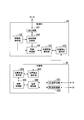
- FIG. 2 is a schematic diagram for explaining an outline of a communication method by the communication system according to the first embodiment of the present invention. It is a schematic diagram for explaining the outline of the obstacle avoidance action by the communication system according to the first embodiment of the present invention.
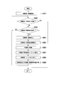
- FIG. 1 is a block diagram illustrating a functional configuration of a communication system according to a first embodiment of the present invention.
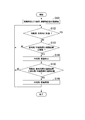
- 4 is a flowchart illustrating an operation of the communication system according to the first exemplary embodiment of the present invention.
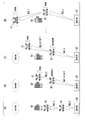
- It is a schematic diagram for explaining the outline of the communication method by the communication system according to the second embodiment of the present invention.
- FIG. 9 is a block diagram illustrating a functional configuration of a communication system according to a second embodiment of the present invention. 6 is a flowchart illustrating an operation of the communication system according to the second exemplary embodiment of the present invention.
- the communication system according to each embodiment described below includes, as an example, a mobile station device and a base station device (fixed station) mounted on a drone moving (flying) toward a destination, if necessary.
- a communication system for performing communication via a mobile station device (relay station) mounted on a drone is simply referred to as a “mobile station”.
- a drone equipped with a mobile station device moving toward a destination is simply referred to as a “mobile station”.
- the base station device is simply referred to as “base station”.
- a drone equipped with a mobile station device serving as a relay station is simply referred to as a “relay station”.
- FIG. 1 is a schematic diagram for explaining an outline of a communication method by the communication system according to the first embodiment of the present invention.
- an obstacle 50 exists between the base station 20 and the destination to which the mobile station 10 goes.
- the mobile station 10 having a link established with the base station 20 moves toward the destination, for example, starting near the base station 20 (S1).
- the mobile station 10 stops moving (S2).
- the mobile station 10 transmits a notification for requesting the base station 20 to arrange the relay station 30 (S3).
- the base station 20 receives the notification transmitted from the mobile station 10.
- the base station 20 transmits, to the relay station 30, a notification for relaying communication between the mobile station 10 and the base station 20.
- the relay station 30 moves into the beam of the radio wave emitted by the base station 20, as shown in FIG. 1B (S4).
- a handover is performed between the mobile station 10 and the base station 20, and links are established between the mobile station 10 and the relay station 30, and between the base station 20 and the relay station 30 (S5).
- the mobile station 10 restarts moving and moves toward the destination along a new moving route that avoids the obstacle 50.
- the relay station 30 changes the relative position of the destination, the mobile station 10, the base station 20, its own relay station 30, and the obstacle 50 with the movement of the mobile station 10.
- the mobile station 10 moves in conjunction with the mobile station 10 so as to maintain a position at which communication between the mobile station 10 and the base station 20 can be relayed.
- the mobile station 10 and the relay station 30 each perform an obstacle avoiding action indicating movement for avoiding the obstacle 50 (S6).
- the mobile station 10 and the relay station 30 work in conjunction with each other to By taking the avoidance action, a communication path between the mobile station 10 and the base station 20 can be secured.
- a plurality of relay stations 30 may relay communication between the mobile station 10 and the base station 20.
- the newly-installed relay station 30 moves relative to the destination, the mobile station 10, another already-installed relay station 30, its own relay station 30, and the obstacle 50 accompanying the movement of the mobile station 10.
- the mobile station 10 and another relay station 30 already deployed so as to maintain a position at which communication between the mobile station 10 and the base station 20 can be relayed in accordance with a change in the local positional relationship. While moving.
- the mobile station 10 and the relay station 30 perform radio communication with the opposite station using, for example, a directional antenna (not shown) (hereinafter, referred to as an “antenna”). Therefore, the mobile station 10 and the relay station 30 have a tracking mechanism for tracking the opposite station. For example, in a narrow beam antenna used for long-distance wireless communication, at a position 10 m away from the beam irradiation position, the width of a radio wave beam emitted from the antenna (hereinafter, referred to as “beam spread”) is It is about 30 cm. Therefore, unless the position of the opposing station to be tracked falls within this beam spread, the mobile station 10 and the relay station 30 cannot track the opposing station.
- beam spread a radio wave beam emitted from the antenna
- the mobile station 10 and the relay station 30 include a camera (not shown), an image processing engine (not shown), and a tracking mechanism (not shown).
- the camera images the direction of the opposite station.
- the camera outputs image data indicating a captured image to the image processing engine.
- the image processing engine analyzes image data input from the camera, and specifies an image area indicating an opposite station in an image based on the image data.
- image processing engine previously holds, for example, image data (master image data) indicating an image captured by the opposite station, and compares the master image data with image data input from the camera, An image area indicating the opposite station in the image may be specified.
- the image processing engine controls the tracking mechanism so that the image area indicating the opposite station is located at the center of the image based on the image data input from the camera.
- the tracking mechanism is configured to be able to control the direction of its own mobile station 10 or its own relay station 30. Thereby, the tracking mechanism can control the imaging direction of the camera provided in the mobile station 10 and the relay station 30 by controlling the direction of the own mobile station 10 or the own relay station 30.
- the imaging direction of the camera and the irradiation direction of the radio wave beam emitted from the antenna match each other.
- the beam is emitted toward the position shown in the center of the image based on the image data input from the camera.
- the mobile station 10 and the relay station 30 detect the obstacle 50 (for example, a shield or a reflector such as a building) by the image processing engine. With the movement of its own wireless station device (mobile station 10 or relay station 30) or the movement of the opposing station, the opposing station moves out of the range of the area that can be tracked by the tracking mechanism under the influence of the obstacle 50 (for example, When it is predicted that the mobile station moves to a position behind the obstacle 50, the wireless station device (the mobile station 10 and the relay station 30) and its own wireless station device (the mobile station 10 or the relay station 30) and the opposite station Move to a position where the clearance can be taken (see through).
- the obstacle 50 for example, a shield or a reflector such as a building
- the movement in the direction in which the clearance can be taken here is, for example, divided by a straight line passing through the position on the plane of the destination to which the mobile station 10 goes and the position on the plane of the obstacle 50 as shown in FIG.
- the relay station 30 moves to the area where the mobile station 10 exists, of the two areas. Note that the movement in the direction in which the clearance can be taken means, for example, that the mobile station 10 exists in two regions divided by a straight line passing through the position on the plane of the mobile station 10 and the position on the plane of the obstacle 50.
- the relay station 30 may be sequentially moved so as to be always located in the area where the relay station 30 is to be operated.
- the mobile station 10 may detect the obstacle 50 using a camera, a sensor, or the like.
- the mobile station 10 or the base station 20 may hold data indicating the position of the obstacle 50 in advance and detect the obstacle 50 based on the data.
- the mobile station 10 may detect the obstacle 50 based on an actual communication degradation state or the like.
- FIG. 3 is a block diagram illustrating a functional configuration of the communication system according to the first embodiment of the present invention.
- the communication system includes a mobile station 10 and a relay station 30.
- the mobile station 10 includes a transceiver 101, a position detection / notification unit 102, a positional relationship analysis unit 103, a movement control unit 104, an obstacle detection unit 105, and a communication connection switching unit 106. You.
- the transceiver 101 communicates with the base station 20 via the relay station 30 or without the relay station 30.
- the transceiver 101 includes an antenna (not shown).
- the position detection / notification unit 102 detects the positions of various objects such as the mobile station 10, the relay station 30, and the obstacle 50 of the own.
- the position detection / notification unit 102 notifies the relay station 30 of the information indicating the detected position of the mobile station 10, the information indicating the position of the obstacle 50, and the information indicating the position of the destination.
- the position detection / notification unit 102 includes, for example, a Global Navigation Satellite System (GNSS) such as a Global Positioning System (GPS) or a Global Navigation Satellite System (GLONASS), a gyro sensor, a position measurement sensor, a distance measurement sensor, Alternatively, it is configured to include a device capable of measuring a position, such as a camera and an image analysis device.
- GNSS Global Navigation Satellite System
- GPS Global Positioning System
- GLONASS Global Navigation Satellite System
- gyro sensor gyro sensor
- a position measurement sensor a distance measurement sensor
- it is configured to include a device capable of measuring a
- the positional relationship analysis unit 103 analyzes the positional relationship between the destination, the own mobile station 10, the base station 20, the relay station 30, and the obstacle 50.
- the information indicating the position of the destination is stored in advance in a storage medium (not shown) provided in the mobile station 10, for example.
- the information indicating the position of the destination is stored in advance in a storage medium (not shown) provided in the base station 20, and the mobile station 10 indicates the position of the destination from the base station 20 as necessary.
- the information may be acquired each time.
- the movement control unit 104 controls the movement of its own mobile station 10 along a movement route to the destination (first movement route) determined based on the positional relationship analyzed by the positional relationship analysis unit 103. I do.
- the movement control unit 104 suspends the movement of the own mobile station 10 (that is, stops the drone that is the own mobile station 10 at the current position).
- the notification is a notification indicating that the obstacle detection unit 105 has detected the obstacle 50 on the movement route to the destination.
- the movement control unit 104 restarts the movement of the mobile station 10 which is inactive in response to the notification from the communication connection switching unit 106.
- the notification is a notification indicating that the communication connection switching unit 106 has switched to the communication connection with the base station 20 via the new relay station 30.
- the movement control unit 104 moves its own mobile station 10 along a movement route (a second movement route) that avoids the obstacle 50.
- the obstacle detection unit 105 detects an obstacle 50 (for example, a building or the like) existing on the movement route (on the first movement route) of the mobile station 10 moving toward the destination.
- the obstacle detection unit 105 notifies the movement control unit 104 and the communication connection switching unit 106 that the obstacle 50 has been detected.
- the obstacle detection unit 105 includes a device that can detect an obstacle, such as an infrared sensor, an ultrasonic sensor, a camera, and an image analysis device.
- the communication connection switching unit 106 Upon being notified that the obstacle 50 has been detected from the obstacle detection unit 105, the communication connection switching unit 106 sends a notification indicating a request to deploy the relay station 30 to the base station 20 via the transceiver 101. Send. As a result, under the control of the base station 20, a new relay station 30 is deployed. Note that the mobile station 10 may directly request the relay station 30 to relay the communication between the mobile station 10 and the base station 20.
- the communication connection switching unit 106 detects that the transceiver 101 has received the radio wave transmitted from the new relay station 30, it performs a handover, and communicates with its own mobile station 10 via the new relay station 30. The link is switched so that communication with the relay station 30 is performed.
- the relay station 30 includes a first transceiver 301, a second transceiver 302, a position detection / notification unit 303, a positional relationship analysis unit 304, a movement control unit 305, and a radio wave detection unit 306. Is done.
- the first transceiver 301 communicates with the mobile station 10.
- the second transceiver 302 communicates with the base station 20.
- the first transceiver 301 and the second transceiver 302 each include an antenna (not shown).
- the position detection / notification unit 303 detects the positions of various objects such as the relay station 30, the mobile station 10, and the obstacle 50.
- the position detection / notification unit 303 notifies the mobile station 10 of information indicating the detected position of the relay station 30.
- the position detection / notification unit 303 is configured to include a device capable of measuring a position, such as a GNSS such as GPS or GLONASS, a gyro sensor, a position measurement sensor, a distance measurement sensor, a camera, and an image analysis device. .
- the positional relationship analysis unit 304 analyzes the positional relationship among the relay station 30, the mobile station 10, the base station 20, and the obstacle 50.
- the movement control unit 305 moves its own relay station 30 to an arbitrary position within the irradiation range of the beam of the radio wave emitted from the base station 20 in response to the notification from the base station 20.
- the notification is a notification indicating a request for relaying communication between the mobile station 10 and the base station 20. Further, the movement control unit 305 moves the own relay station 30 based on the positional relationship analyzed by the positional relationship analyzing unit 304 so as to maintain a position where the mobile station 10 and the base station 20 can be seen through. Control.
- the movement control unit 305 determines which of the two areas divided by a straight line that passes through the position on the plane of the destination to which the mobile station 10 goes and the position on the plane of the obstacle 50 where the mobile station 10 exists.
- the movement of the own relay station 30 may be controlled so that the relay station 30 is located in the area of.
- the movement control unit 305 determines the position in the region where the mobile station 10 exists, of the two regions divided by a straight line passing through the position on the plane of the mobile station 10 and the position on the plane of the obstacle 50. So that the movement of the relay station 30 may be controlled.
- the radio wave detection unit 306 Upon detecting a radio wave transmitted from the base station 20, the radio wave detection unit 306 establishes a link between the base station 20 and its own relay station. Further, the radio wave detecting unit 306 transmits a radio wave to the mobile station 10 via the first transceiver 301. This allows the mobile station 10 to recognize that its own relay station 30 exists at a position where the communication between the mobile station 10 and the base station 20 can be relayed.
- FIG. 4 is a flowchart showing the operation of the communication system according to the first embodiment of the present invention.
- the mobile station 10 starts moving along the moving route to the destination (Step S001).
- the processing shown by the flowchart in FIG. 4 ends. If the mobile station 10 has not reached the destination (step S002: No), the mobile station 10 continues to move.
- step S003 When the mobile station 10 has not detected that the obstacle 50 exists on the moving route to the destination (step S003, No), the mobile station 10 continues to move.
- step S003: Yes When the mobile station 10 detects that the obstacle 50 is present on the moving route to the destination (step S003: Yes), the mobile station 10 stops moving (step S004), Then, a notification indicating a request to deploy a new relay station 30 is transmitted (step S005).
- the relay station 30 moves its own relay station 30 to an arbitrary position within the irradiation range of the radio wave beam emitted from the base station 20 in response to the notification from the base station 20 (step S006).
- the notification is a notification indicating a request for relaying communication between the mobile station 10 and the base station 20.
- the relay station 30 establishes a link between the base station 20 and its own relay station (step S007). Also, the relay station 30 transmits a radio wave to the mobile station 10.
- the mobile station 10 Upon receiving the radio wave transmitted from the relay station 30, the mobile station 10 performs a handover so that communication between the mobile station 10 and the base station 20 is performed via the relay station 30, and switches the link ( Step S008).
- the link between the mobile station 10 and the relay station 30 and the link between the base station 20 and the relay station 30 are established, the mobile station 10 moves along the moving route to avoid the obstacle 50. Resume the move.
- relay station 30 moves in accordance with the movement of mobile station 10 so as to maintain a position where communication between mobile station 10 and base station 20 can be relayed. That is, the mobile station 10 and the relay station 30 start an obstacle avoiding action (step S009).
- step S002 the mobile station 10 and the relay station 30 repeat the processing from step S002 to step S009.
- the communication system according to the second embodiment performs communication quality control in addition to the processing performed by the communication system according to the first embodiment.
- the communication system according to the second embodiment has a predetermined communication quality in the communication between the mobile station 10 and the relay station 30 and the communication between the base station 20 and the relay station 30. Control is performed so that a difference larger than the threshold value does not occur.
- the communication system according to the second embodiment has a bottleneck in that the communication quality only in a partial section of the communication path between the mobile station 10 and the base station 20 becomes a bottleneck, and the entire communication path Communication quality can be prevented from deteriorating.
- the base station 20 and the relay station 30 when the distance between the base station 20 and the relay station 30 is increased by the relay station 30 moving for clearance with the mobile station 10, the base station When the communication quality of the communication between the station 20 and the relay station 30 becomes equal to or less than a predetermined threshold, the relay station 30 stops moving, and only the mobile station 10 moves toward the destination. This is because if the distance between the base station 20 and the relay station 30 is further increased by the further movement of the relay station 30, only the communication quality between the base station 20 and the relay station 30 is further reduced, which is a bottleneck. This is because it is expected that the communication quality of the entire communication path will deteriorate as a bottleneck.
- the communication quality index is an index that takes a continuous value such as a reception level or a throughput
- the above is the same as above.
- the communication quality index is based on MCS (Modulation and Coding Scheme, modulation scheme and coding rate).
- the index may be a discrete value such as an index value.
- FIG. 5 is a schematic diagram for explaining an outline of a communication method by the communication system according to the second embodiment of the present invention.
- FIG. 5 shows, as an example, a communication method when the communication quality index is an MCS index value.
- the MCS index value in the communication between the mobile station 10 and the relay station 30, and the The MCS index values in the communication with the station 30 are both “9”, and have the same communication quality.
- the relay station 30 moves as the mobile station 10 moves toward the destination, the distance between the base station 20 and the relay station 30 becomes longer, so that the reception level decreases and the like.
- the index value of the MCS in the communication between the base station 20 and the relay station 30 decreases to “8”. In this case, the relay station 30 stops moving. As a result, only the mobile station 10 moves toward the destination.
- the distance between the mobile station 10 and the relay station 30 increases, which causes a decrease in the reception level and the like. For example, as shown in FIG.
- the index value of the MCS in the communication between the mobile station 10 and the relay station 30 decreases to “8”.
- the MCS index value in the communication between the mobile station 10 and the relay station 30 and the MCS index value in the communication between the base station 20 and the relay station 30 are both “8” and there is no difference in the communication quality. As a result, the relay station 30 resumes the movement.
- the mobile station 10 moves toward the destination while the relay station 30 repeats the operations of FIGS. 5 (A) to 5 (C).
- the communication between the mobile station 10 and the relay station 30 and the communication between the base station 20 and the relay station 30 can be performed.
- the communication system according to the second embodiment prevents the communication quality of a specific section of the communication path from rapidly decreasing, and reduces the communication quality so that the communication quality of the entire communication path decreases gradually. Control can be performed.
- FIG. 6 is a block diagram illustrating a functional configuration of the communication system according to the second embodiment of the present invention.
- the communication system includes a mobile station 10 and a relay station 30R.
- the same reference numerals are given to functional blocks having the same configuration as the functional blocks included in the communication device according to the first embodiment described with reference to FIG. Further, a repeated description will be omitted, and only a configuration newly added to the configuration of the communication device according to the first embodiment will be described below.
- the mobile station 10 includes a transceiver 101, a position detection / notification unit 102, a positional relationship analysis unit 103, a movement control unit 104, an obstacle detection unit 105, and a communication connection switching unit 106. You.
- the relay station 30R includes a first transceiver 301R, a second transceiver 302R, a position detection / notification unit 303R, a positional relationship analysis unit 304, a movement control unit 305R, and a radio wave detection unit 306. Is done.
- the first transceiver 301R measures the communication quality of communication between the mobile station 10 and its own relay station 30R.
- the first transceiver 301R outputs the measured communication quality value to the position detection / notification unit 303R.
- the second transceiver 302R measures the communication quality of the communication between the base station 20 and its own relay station 30R.
- the second transceiver 302R outputs the measured communication quality value to the position detection / notification unit 303R.
- the position detection / notification unit 306R transmits the information to the own relay station 30 via the movement control unit 305R. Pause movement. Thereafter, the position detection / notification unit 306R determines that the value indicating the communication quality of the communication between the base station 20 and its own relay station 30R indicates the communication quality of the communication between the mobile station 10 and its own relay station 30R. When the value becomes equal to or more than the indicated value, the movement of the own relay station 30 is restarted via the movement control unit 305R.
- FIG. 7 is a flowchart showing the operation of the communication system according to the second embodiment of the present invention. Note that the flowchart shown in FIG. 7 shows the operation after the mobile station 10 and the relay station 30 have performed the obstacle avoidance action (that is, step S009 of the flowchart shown in FIG. 4). Note that only operations newly added to the operations of the communication device according to the first embodiment will be described below.
- the mobile station 10 and the relay station 30 start an obstacle avoiding action (step S101).
- Step S102: Yes the processing shown by the flowchart in FIG. 7 ends.
- step S002: No the mobile station 10 and the relay station 30 continue the obstacle avoiding action.
- a value indicating the communication quality of the communication between the base station 20 and the relay station 30 (in addition to the MCS, a transmission rate, a previously measured throughput, a received signal strength (RSSI; Received Signal Strength Indication), etc.) are assumed. ) Is not less than or equal to the predetermined threshold (step S103: No), the mobile station 10 and the relay station 30 continue the obstacle avoiding action.
- the relay station 30 stops moving (step S104).
- step S105: No If the value indicating the communication quality of the communication between the base station 20 and the relay station 30 is smaller than the value indicating the communication quality of the communication between the mobile station 10 and its own relay station 30 (step S105: No), The relay station 30 does not restart the movement.
- step S105: Yes When the value indicating the communication quality of the communication between the base station 20 and the relay station 30 is equal to or greater than the value indicating the communication quality of the communication between the mobile station 10 and its own relay station 30 (step S105: Yes) ), Relay station 30 resumes movement (step S106).
- the mobile station 10 suspends the movement when detecting the obstacle 50 to the communication path while moving to the destination, and stops the movement of the base station 20.
- the relay station 30 transmits a deployment request for the relay station 30.
- relay station 30 moves to an arbitrary position between the current position of mobile station 10 and the position of base station 20, and mobile station 10 and base station 20 perform handover.
- the mobile station 10 resumes the movement, and the relay station 30 sets the mobile station 10 so that the communication path connecting the mobile station 10, its own relay station 30, and the base station 20 bypasses the obstacle 50. Move according to the position of.
- the communication system allows the mobile station 10 and the base station 20 to communicate with each other even when an unknown obstacle 50 exists between the base station 20 and the destination to which the mobile station 10 goes.
- a communication path with the station 20 can be secured.
- the configuration of the communication system according to each of the above-described embodiments is, for example, used for controlling communication between the mobile station and the base station when the mobile station moves farther than the initial movement plan. However, it is also applicable.
- a part or all of the mobile station 10 and the relay station 30 in the above-described embodiment may be realized by a computer.
- a program for realizing this function may be recorded on a computer-readable recording medium, and the program recorded on this recording medium may be read and executed by a computer system.
- the “computer system” includes an OS and hardware such as peripheral devices.
- the “computer-readable recording medium” refers to a portable medium such as a flexible disk, a magneto-optical disk, a ROM, and a CD-ROM, and a storage device such as a hard disk built in a computer system.
- the “computer-readable recording medium” refers to a communication line for transmitting a program via a network such as the Internet or a communication line such as a telephone line.
- a program may include a program that holds a program for a certain period of time, such as a volatile memory in a computer system serving as a server or a client in that case.
- the program may be for realizing a part of the functions described above, or may be a program that can realize the functions described above in combination with a program already recorded in a computer system. It may be realized by using a programmable logic device such as an FPGA (Field Programmable Gate Array).
- FPGA Field Programmable Gate Array
Landscapes
- Engineering & Computer Science (AREA)
- Computer Networks & Wireless Communication (AREA)
- Signal Processing (AREA)
- Physics & Mathematics (AREA)
- Astronomy & Astrophysics (AREA)
- Aviation & Aerospace Engineering (AREA)
- General Physics & Mathematics (AREA)
- Mobile Radio Communication Systems (AREA)
Abstract
無線局との通信を行い所定の目的地へ向かって移動する移動局と、移動局と無線局との間の通信を中継する中継局と、を有する通信システムは、目的地へ向かう第1の移動ルートに沿って移動している場合において第1の移動ルート上に存在する障害物を検知した場合に移動を休止し、移動を休止している場合において中継局を介した移動局と無線局との間の通信が確立した場合に障害物を回避して目的地へ向かう第2の移動ルートに沿って移動する移動局と、移動局が第2の移動ルートに沿って移動する場合に、移動局の移動に応じて移動局と無線局との間の通信を中継可能な位置を維持するように移動する中継局と、を有する。
Description
本発明は、通信システム及び通信方法に関する。
無線通信において、固定局装置対固定局装置の間の通信、移動局装置対基地局装置の間の通信のほか、昨今、移動局装置を中継局とする移動局装置対基地局装置の間の通信、及び、移動局装置同士の間の通信(M2M;Machine-to-Machine)が注目されている。上記の無線通信においては、例えばWi-Fi(ワイファイ)に代表されるIEEE(The Institute of Electrical and Electronics Engineers, Inc.)802.11規格に基づく無線通信方式、及び、例えばLTE(登録商標)(Long Term Evolution)等のcellular(セルラー)方式の無線通信方式が一般に用いられている。
しかしながら、移動局がある程度広い範囲を移動しつつ総スループット数が100Mbps以上となるような大容量伝送を行う場合においては、上記の無線通信方式は適当ではない場合がある。なぜならば、無線局装置間の距離が遠くなるほど無線局装置において受信される電力が減衰してしまうため、所望のC/N比(Carrier to Noise Ratio;搬送波対雑音比)を満たさなくなるためである。
移動局がある程度広い範囲を移動しつつ大容量伝送を行うためには、例えば28GHzあるいは60GHz等のミリ波帯の周波数を利用する必要がある。ミリ波は波長が短いことから、その伝わり方として、直進性が強く、建物等の障害物の陰に回り込み難いという特性がある。そこで、無線局装置同士が直接通信することが困難である場合において、他の無線局装置(中継局)を経由して通信を行うマルチホップネットワークを用いることが考えられる(例えば、非特許文献1)。
阪田史郎 他,「アドホックネットワークと無線LANメッシュネットワーク」,電子情報通信学会論文誌B Vol.J89-B No.6,pp.811-823,社団法人 電子情報通信学会,2006年
ところで、例えば、目的地へ向かって移動するドローン(Drone)等に搭載された移動局装置が基地局装置とミリ波を用いて通信を行う場合において、目的地と基地局装置との間、又は目的地と中継局との間に建物等の障害物が存在する場合がある。この場合、移動局装置が目的地に到達すると、移動局装置は、基地局装置又は中継局の位置に対して障害物の陰に位置することになるため、通信を行うことが困難になる。
そこで上記のマルチホップネットワークを用いて障害物を回避する通信路を構築することが考えられるが、この場合、移動局装置が障害物を回避して移動する行動に伴って生じる、目的地、移動局装置、基地局装置、中継局及び障害物の位置関係の変化に応じて、マルチホップネットワークの構成を動的に制御する必要がある。しかしながら、非特許文献1に記載の技術は、例えば、災害時におけるライフラインとして、既設の有線ネットワークのバックアップとして一時的な通信手段を確保することを目的としていることから、動的にマルチホップネットワークの構成を制御することは難しい。このように従来技術では、障害物が存在する場合には、移動局装置と基地局装置との間の通信路を確保することが難しいことがあるという課題がある。
そこで上記のマルチホップネットワークを用いて障害物を回避する通信路を構築することが考えられるが、この場合、移動局装置が障害物を回避して移動する行動に伴って生じる、目的地、移動局装置、基地局装置、中継局及び障害物の位置関係の変化に応じて、マルチホップネットワークの構成を動的に制御する必要がある。しかしながら、非特許文献1に記載の技術は、例えば、災害時におけるライフラインとして、既設の有線ネットワークのバックアップとして一時的な通信手段を確保することを目的としていることから、動的にマルチホップネットワークの構成を制御することは難しい。このように従来技術では、障害物が存在する場合には、移動局装置と基地局装置との間の通信路を確保することが難しいことがあるという課題がある。
上記事情に鑑み、本発明は、障害物が存在する場合であっても移動局装置と無線局装置との間の通信路を確保することができる技術の提供を目的としている。
本発明の一態様は、無線局との通信を行い所定の目的地へ向かって移動する移動局と、前記移動局と前記無線局との間の通信を中継する中継局と、を有する通信システムであって、前記移動局は、前記目的地へ向かう第1の移動ルートに沿って移動している場合において前記第1の移動ルート上に存在する障害物を検知した場合に移動を休止し、前記移動を休止している場合において前記中継局を介した前記移動局と前記無線局との間の通信が確立した場合に前記障害物を回避して前記目的地へ向かう第2の移動ルートに沿って移動し、前記中継局は、前記移動局が前記第2の移動ルートに沿って移動する場合に、前記移動局の移動に応じて前記移動局と前記無線局との間の通信を中継可能な位置を維持するように移動する通信システムである。
また、本発明の一態様は、上記の通信システムであって、前記中継局は、前記移動局及び前記無線局を見通すことができる位置を維持するように移動することにより前記中継可能な位置を維持する。
また、本発明の一態様は、上記の通信システムであって、前記中継局は、前記目的地の平面上の位置と前記障害物の平面上の位置とを通る直線によって分割される2つの領域のうち、前記移動局が存在するほうの領域に位置するように移動する。
また、本発明の一態様は、上記の通信システムであって、前記中継局は、前記移動局の平面上の位置と前記障害物の平面上の位置とを通る直線によって分割される2つの領域のうち、前記移動局が存在するほうの領域に位置するように移動する。
また、本発明の一態様は、上記の通信システムであって、前記中継局は、前記移動局と前記中継局との間の通信の通信品質を示す値と、前記無線局と前記中継局との間の通信の通信品質を示す値と、の差が所定の閾値以下になるように移動する。
また、本発明の一態様は、無線局との通信を行い所定の目的地へ向かって移動する移動局と、前記移動局と前記無線局との間の通信を中継する中継局と、による通信方法であって、前記移動局が、前記目的地へ向かう第1の移動ルートに沿って移動している場合において前記第1の移動ルート上に存在する障害物を検知した場合に移動を休止するステップと、前記移動局が、前記移動を休止している場合において前記中継局を介した前記移動局と前記無線局との間の通信が確立した場合に前記障害物を回避して前記目的地へ向かう第2の移動ルートに沿って移動するステップと、前記障害物が前記第2の移動ルートに沿って移動する場合に、前記中継局が、前記移動局の移動に応じて前記移動局と前記無線局との間の通信を中継可能な位置を維持するように移動するステップと、を有する通信方法である。
本発明により、障害物が存在する場合であっても移動局装置と無線局装置との間の通信路を確保することができる。
以下、本発明の実施形態に係る通信システムついて、図面を参照しながら説明する。
以下に説明する各実施形態に係る通信システムは、一例として、目的地へ向かって移動(飛行)するドローンに搭載された移動局装置と基地局装置(固定局)とが、必要に応じて他のドローンに搭載された移動局装置(中継局)を経由して、通信を行うための通信システムである。
以下、目的地へ向かって移動する移動局装置を搭載するドローンを、単に「移動局」という。また、基地局装置を、単に「基地局」という。また、中継局となる移動局装置を搭載するドローンを、単に「中継局」という。
以下に説明する各実施形態に係る通信システムは、一例として、目的地へ向かって移動(飛行)するドローンに搭載された移動局装置と基地局装置(固定局)とが、必要に応じて他のドローンに搭載された移動局装置(中継局)を経由して、通信を行うための通信システムである。
以下、目的地へ向かって移動する移動局装置を搭載するドローンを、単に「移動局」という。また、基地局装置を、単に「基地局」という。また、中継局となる移動局装置を搭載するドローンを、単に「中継局」という。
<第1の実施形態>
以下、第1の実施形態に係る通信システムついて説明する。
図1は、本発明の第1の実施形態に係る通信システムによる通信方法の概要を説明するための模式図である。
以下、第1の実施形態に係る通信システムついて説明する。
図1は、本発明の第1の実施形態に係る通信システムによる通信方法の概要を説明するための模式図である。
図1(A)に示すように、移動局10が向かう目的地と基地局20との間には、障害物50(例えば建物等)が存在する。まず、基地局20とリンクが確立している移動局10は、例えば基地局20の近傍を出発点として、目的地へ向かって移動する(S1)。移動局10は、目的地への移動ルート上に障害物50を検知した場合、移動を休止する(S2)。移動局10は、基地局20に対して中継局30の配備を要求するための通知を送信する(S3)。基地局20は、移動局10から送信された通知を受信する。
次に、基地局20は、中継局30に対して、移動局10と基地局20との間の通信の中継を行わせるための通知を送信する。中継局30は、基地局20から送信された通知を受信すると、図1(B)に示すように、基地局20が照射する電波のビーム内へ移動する(S4)。これにより、移動局10及び基地局20においてハンドオーバーが行われ、移動局10と中継局30との間、及び基地局20と中継局30との間のリンクが確立される(S5)。
次に、移動局10は、中継局30との間のリンクが確立されると、移動を再開し、障害物50を回避する新たな移動ルートに沿って目的地へ向かって移動する。また、中継局30は、移動局10の移動に伴う、目的地、移動局10、基地局20、自己の中継局30及び障害物50の相対的な位置関係の変化に応じて、移動局10と基地局20との間の通信を中継可能な位置を維持するように、移動局10と連動しながら移動する。このように、移動局10と中継局30とは、障害物50を回避するための移動を示す障害物回避行動をそれぞれ行う(S6)。
以上により、第1の実施形態に係る通信システムによれば、移動局10の移動ルート上に障害物50が存在する場合であっても、移動局10と中継局30とが連動して障害物回避行動をとることによって、移動局10と基地局20との間の通信路を確保することができる。
なお、例えば、障害物50が複数存在する場合等においては、移動局10と基地局20との間の通信を、複数の中継局30が中継するようにしてもよい。この場合、新たに配備された中継局30は、移動局10の移動に伴う、目的地、移動局10、既に配備されている他の中継局30、自己の中継局30及び障害物50の相対的な位置関係の変化に応じて、移動局10と基地局20との間の通信を中継可能な位置を維持するように、移動局10及び既に配備されている他の中継局30と連動しながら移動する。
なお、移動局10及び中継局30は、例えば、指向性アンテナ(図示せず)(以下「アンテナ」という。)を用いて対向局との無線通信を行う。そのため、移動局10及び中継局30は、対向局を追尾するための追尾機構を備えている。なお、例えば、長距離の無線通信に用いられる狭ビームアンテナでは、ビームの照射位置から10m先の位置においては、アンテナから照射される電波のビームの幅(以下「ビーム広がり」という。)は、30cm程度になる。したがって、追尾対象の対向局の位置がこのビーム広がりに収まっていなければ、移動局10及び中継局30は、対向局を追尾することができない。
以下、移動局10及び中継局30による、上記の障害物回避行動の一例について説明する。
移動局10及び中継局30は、カメラ(図示せず)、画像処理エンジン(図示せず)及び追尾機構(図示せず)を備える。カメラは、対向局の方向を撮像する。カメラは、撮像された画像を示す画像データを画像処理エンジンへ出力する。画像処理エンジンは、カメラから入力された画像データを解析し、画像データに基づく画像内における、対向局を示す画像領域を特定する。
移動局10及び中継局30は、カメラ(図示せず)、画像処理エンジン(図示せず)及び追尾機構(図示せず)を備える。カメラは、対向局の方向を撮像する。カメラは、撮像された画像を示す画像データを画像処理エンジンへ出力する。画像処理エンジンは、カメラから入力された画像データを解析し、画像データに基づく画像内における、対向局を示す画像領域を特定する。
なお、画像処理エンジンは、例えば、対向局が撮像された画像を示す画像データ(マスター画像データ)を予め保持しており、マスター画像データとカメラから入力された画像データとを照合することによって、画像内における対向局を示す画像領域を特定するようにしてもよい。
また、画像処理エンジンは、対向局を示す画像領域が、カメラから入力される画像データに基づく画像の中央に位置するように、追尾機構を制御する。追尾機構は、自己の移動局10又は自己の中継局30の向きを制御可能に構成されている。これにより、追尾機構は、自己の移動局10又は自己の中継局30の向きを制御することによって、移動局10及び中継局30が備えるカメラの撮像方向を制御することができる。
なお、カメラの撮像方向と、アンテナから照射される電波のビームの照射方向とは、一致するように構成されているものとする。これにより、カメラから入力される画像データに基づく画像の中央に写っている位置に向けて、ビームが照射されることになる。
移動局10及び中継局30は、画像処理エンジンによって障害物50(例えば、建物等の遮蔽物及び反射物)を検出する。自己の無線局装置(移動局10又は中継局30)の移動又は対向局の移動に伴って、対向局が、障害物50の影響によって追尾機構で追尾可能な領域の範囲外の位置(例えば、障害物50の陰になる位置)へ移動することが予測される場合、無線局装置(移動局10及び中継局30)は、自己の無線局装置(移動局10又は中継局30)と対向局との間でクリアランスが取れる(見通せる)位置へ移動する。
ここでいうクリアランスが取れる方向への移動とは、例えば、図2に示すように、移動局10が向かう目的地の平面上の位置と障害物50の平面上の位置とを通る直線によって分割される2つの領域のうち、移動局10が存在するほうの領域に中継局30が移動することである。なお、クリアランスが取れる方向への移動とは、例えば、移動局10の平面上の位置と障害物50の平面上の位置とを通る直線によって分割される2つの領域のうち、移動局10が存在するほうの領域に中継局30が常に位置するように逐次移動することであってもよい。
なお、障害物50の検知の方法として、例えば、移動局10が、カメラやセンサ等によって障害物50を検知するようにしてもよい。あるいは、例えば、移動局10又は基地局20が、障害物50の位置を示すデータを予め保持しておき、該データに基づいて障害物50を検知するようにしてもよい。あるいは、例えば、移動局10が、実際の通信の劣化状況等から障害物50を検知するようにしてもよい。
[通信システムの機能構成]
以下、通信システムの機能構成について、図面を参照しながら説明する。
図3は、本発明の第1の実施形態に係る通信システムの機能構成を示すブロック図である。図3に示すように、通信システムは、移動局10と、中継局30と、を含んで構成される。
以下、通信システムの機能構成について、図面を参照しながら説明する。
図3は、本発明の第1の実施形態に係る通信システムの機能構成を示すブロック図である。図3に示すように、通信システムは、移動局10と、中継局30と、を含んで構成される。
移動局10は、送受信機101と、位置検出・通知部102と、位置関係解析部103と、移動制御部104と、障害物検知部105と、通信接続切替部106と、を含んで構成される。
送受信機101は、中継局30を介して、又は中継局30を介さずに、基地局20と通信を行う。送受信機101は、アンテナ(図示せず)を含んで構成される。
位置検出・通知部102は、自己の移動局10、中継局30及び障害物50等の各種物体の位置を検出する。また、位置検出・通知部102は、検出した自己の移動局10の位置を示す情報、障害物50の位置を示す情報、及び目的地の位置を示す情報を、中継局30に対して通知する。位置検出・通知部102は、例えば、GPS(Global Positioning System)やGLONASS(Global Navigation Satellite System)等のGNSS(Global Navigation Satellite System;全球測位衛星システム)、ジャイロセンサ、位置測定センサ、距離測定センサ、又は、カメラ及び画像解析装置等の、位置を測定することができる装置を含んで構成される。
位置関係解析部103は、目的地、自己の移動局10、基地局20、中継局30及び障害物50のそれぞれの位置関係を解析する。
なお、目的地の位置を示す情報は、例えば、移動局10が備える記憶媒体(図示せず)に予め記憶されている。あるいは、目的地の位置を示す情報は、予め基地局20が備える記憶媒体(図示せず)に予め記憶されており、必要に応じて移動局10が、基地局20から目的地の位置を示す情報をその都度取得する構成であってもよい。
なお、目的地の位置を示す情報は、例えば、移動局10が備える記憶媒体(図示せず)に予め記憶されている。あるいは、目的地の位置を示す情報は、予め基地局20が備える記憶媒体(図示せず)に予め記憶されており、必要に応じて移動局10が、基地局20から目的地の位置を示す情報をその都度取得する構成であってもよい。
移動制御部104は、位置関係解析部103によって解析された位置関係に基づいて決定された、目的地への移動ルート(第1の移動ルート)に沿って、自己の移動局10の移動を制御する。
また、移動制御部104は、障害物検知部105からの通知に応じて、自己の移動局10の移動を休止させる(すなわち、自己の移動局10であるドローンを現在位置で静止させる)。当該通知は、障害物検知部105が、目的地への移動ルート上に障害物50を検知したことを示す通知である。
また、移動制御部104は、通信接続切替部106からの通知に応じて、休止中の自己の移動局10の移動を再開させる。当該通知は、通信接続切替部106が、新たな中継局30を介した基地局20との通信接続に切り替えたこと示す通知である。この場合、移動制御部104は、障害物50を回避する移動ルート(第2の移動ルート)に沿って、自己の移動局10を移動させる。
また、移動制御部104は、障害物検知部105からの通知に応じて、自己の移動局10の移動を休止させる(すなわち、自己の移動局10であるドローンを現在位置で静止させる)。当該通知は、障害物検知部105が、目的地への移動ルート上に障害物50を検知したことを示す通知である。
また、移動制御部104は、通信接続切替部106からの通知に応じて、休止中の自己の移動局10の移動を再開させる。当該通知は、通信接続切替部106が、新たな中継局30を介した基地局20との通信接続に切り替えたこと示す通知である。この場合、移動制御部104は、障害物50を回避する移動ルート(第2の移動ルート)に沿って、自己の移動局10を移動させる。
障害物検知部105は、目的地へ向かって移動する移動局10の移動ルート上(第1の移動ルート上)に存在する障害物50(例えば、建物等)を検知する。障害物検知部105は、移動制御部104及び通信接続切替部106に対して、障害物50を検知したことを通知する。障害物検知部105は、例えば、赤外線センサ、超音波センサ、カメラ及び画像解析装置等の、障害物を検知することができる装置を含んで構成される。
通信接続切替部106は、障害物検知部105から障害物50を検知したことが通知されると、送受信機101を介して、基地局20に対し、中継局30を配備させる要求を示す通知を送信する。これにより、基地局20による制御のもと、新たな中継局30の配備が行われる。なお、移動局10が、直接、中継局30に対して、自己の移動局10と基地局20との通信を中継させるための要求を行う構成であってもよい。
また、通信接続切替部106は、送受信機101が新たな中継局30から送出された電波を受信したことを検知すると、ハンドオーバーを行い、新たな中継局30を介して自己の移動局10と中継局30との通信が行わるように、リンクを切り替える。
また、通信接続切替部106は、送受信機101が新たな中継局30から送出された電波を受信したことを検知すると、ハンドオーバーを行い、新たな中継局30を介して自己の移動局10と中継局30との通信が行わるように、リンクを切り替える。
中継局30は、第1送受信機301と、第2送受信機302と、位置検出・通知部303と、位置関係解析部304と、移動制御部305と、電波検知部306と、を含んで構成される。
第1送受信機301は、移動局10と通信を行う。第2送受信機302は、基地局20と通信を行う。第1送受信機301及び第2送受信機302は、それぞれアンテナ(図示せず)を含んで構成される。
位置検出・通知部303は、自己の中継局30、移動局10及び障害物50等の各種物体の位置を検出する。また、位置検出・通知部303は、検出した自己の中継局30の位置を示す情報を移動局10に対して通知する。位置検出・通知部303は、例えば、GPSやGLONASS等のGNSS、ジャイロセンサ、位置測定センサ、距離測定センサ、カメラ及び画像解析装置等の、位置を測定することができる装置を含んで構成される。
位置関係解析部304は、自己の中継局30、移動局10、基地局20及び障害物50のそれぞれの位置関係を解析する。
移動制御部305は、基地局20からの通知に応じて、基地局20から照射される電波のビームの照射範囲内の任意の位置へ、自己の中継局30を移動させる。当該通知は、移動局10と基地局20との間の通信を中継する要求を示す通知である。
また、移動制御部305は、位置関係解析部304によって解析された位置関係に基づいて、移動局10及び基地局20をそれぞれ見通すことができる位置を維持するように、自己の中継局30の移動を制御する。
また、移動制御部305は、位置関係解析部304によって解析された位置関係に基づいて、移動局10及び基地局20をそれぞれ見通すことができる位置を維持するように、自己の中継局30の移動を制御する。
なお、移動制御部305は、移動局10が向かう目的地の平面上の位置と障害物50の平面上の位置とを通る直線によって分割される2つの領域のうち、移動局10が存在するほうの領域に位置するように、自己の中継局30の移動を制御してもよい。または、移動制御部305は、移動局10の平面上の位置と障害物50の平面上の位置とを通る直線によって分割される2つの領域のうち、移動局10が存在するほうの領域に位置するように、自己の中継局30の移動を制御してもよい。
電波検知部306は、基地局20から送出される電波を検知すると、基地局20と自己の中継局との間のリンクを確立する。また、電波検知部306は、移動局10に対し、第1送受信機301を介して電波を送出する。これにより、移動局10に対して、自己の中継局30が移動局10と基地局20との間の通信を中継可能な位置に存在することを認識させることができる。
[通信システムの動作]
以下、通信システムの動作の一例について、図面を参照しながら説明する。
図4は、本発明の第1の実施形態に係る通信システムの動作を示すフローチャートである。
以下、通信システムの動作の一例について、図面を参照しながら説明する。
図4は、本発明の第1の実施形態に係る通信システムの動作を示すフローチャートである。
移動局10は、目的地へ向かう移動ルートに沿って、移動を開始する(ステップS001)。
移動局10が目的地に到達した場合(ステップS002・Yes)、図4のフローチャートが示す処理が終了する。
移動局10が目的地に到達していない場合(ステップS002・No)、移動局10は移動を継続する。
移動局10が目的地に到達した場合(ステップS002・Yes)、図4のフローチャートが示す処理が終了する。
移動局10が目的地に到達していない場合(ステップS002・No)、移動局10は移動を継続する。
移動局10が、目的地へ向かう移動ルート上に障害物50が存在することを検知していない場合(ステップS003・No)、移動局10は移動を継続する。
移動局10が、目的地へ向かう移動ルート上に障害物50が存在することを検知した場合(ステップS003・Yes)、移動局10は移動を休止し(ステップS004)、基地局20に対して、新たな中継局30を配備させる要求を示す通知を送信する(ステップS005)。
移動局10が、目的地へ向かう移動ルート上に障害物50が存在することを検知した場合(ステップS003・Yes)、移動局10は移動を休止し(ステップS004)、基地局20に対して、新たな中継局30を配備させる要求を示す通知を送信する(ステップS005)。
中継局30は、基地局20からの通知に応じて、基地局20から照射される電波のビームの照射範囲内である任意の位置へ、自己の中継局30を移動させる(ステップS006)。当該通知は、移動局10と基地局20との間の通信を中継する要求を示す通知である。
中継局30は、基地局20から送出される電波を検知すると、基地局20と自己の中継局との間のリンクを確立する(ステップS007)。また、中継局30は、移動局10に対して電波を送出する。
中継局30は、基地局20から送出される電波を検知すると、基地局20と自己の中継局との間のリンクを確立する(ステップS007)。また、中継局30は、移動局10に対して電波を送出する。
移動局10は、中継局30から送出された電波を受信すると、当該中継局30を介して自己の移動局10と基地局20との通信が行われるようにハンドオーバーを行い、リンクを切り替える(ステップS008)。
移動局10と中継局30との間のリンク、及び、基地局20と中継局30との間のリンクがそれぞれ確立されると、移動局10は、障害物50を回避する移動ルートに沿って移動を再開する。また、中継局30は、移動局10の移動に応じて、移動局10と基地局20との間の通信を中継可能な位置を維持するように移動する。すなわち、移動局10と中継局30とが、障害物回避行動を開始する(ステップS009)。
移動局10と中継局30との間のリンク、及び、基地局20と中継局30との間のリンクがそれぞれ確立されると、移動局10は、障害物50を回避する移動ルートに沿って移動を再開する。また、中継局30は、移動局10の移動に応じて、移動局10と基地局20との間の通信を中継可能な位置を維持するように移動する。すなわち、移動局10と中継局30とが、障害物回避行動を開始する(ステップS009)。
移動局10が目的地に到達するまで、移動局10及び中継局30は上記ステップS002からステップS009までの処理を繰り返す。
<第2の実施形態>
以下、本発明の第2の実施形態について説明する。
以下、本発明の第2の実施形態について説明する。
第2の実施形態に係る通信システムは、上述した第1の実施形態に係る通信システムによる処理に加えて、通信品質に関する制御を行う。具体的には、第2の実施形態に係る通信システムは、移動局10と中継局30との間の通信と、基地局20と中継局30との間の通信と、において通信品質に所定の閾値以上の差が生じないように制御する。これにより、第2の実施形態に係る通信システムは、移動局10と基地局20との間の通信路の一部区間の通信品質のみが大幅に低下することがボトルネックとなって通信路全体の通信品質が低下することを防止することができる。
第2の実施形態に係る通信システムにおいては、中継局30が移動局10とのクリアランスをとるために移動することによって基地局20と中継局30との間の距離が遠くなったことにより、基地局20と中継局30との間の通信の通信品質が所定の閾値以下となった場合、中継局30は移動を休止し、移動局10のみが目的地へ向かって移動する。これは、中継局30がさらに移動することによって基地局20と中継局30との間の距離が更に遠くなると、基地局20と中継局30との間の通信品質だけがさらに低下し、これがボトルネックとなって通信路全体の通信品質が低下することが予測されるためである。
中継局30が移動を休止し、移動局10のみが目的地へ向かって移動すると、今度は、移動局10と中継局30との間の距離が遠くなる。これにより、移動局10と中継局30との間の通信の通信品質が低下する。そして、基地局20と中継局30との間の通信の通信品質が、移動局10と中継局30との間の通信の通信品質と同等以上になった時点で、中継局30は移動を再開する。
なお、通信品質の指標が受信レベル又はスループットのように連続値をとる指標である場合には上記の通りであるが、通信品質の指標は、MCS(Modulation and Coding Scheme、変調方式と符号化率の組み合わせ)インデックス値のように離散的な値をとる指標である場合がある。
図5は、本発明の第2の実施形態に係る通信システムによる通信方法の概要を説明するための模式図である。図5は、一例として、通信品質の指標がMCSインデックス値である場合における通信方法を示したものである。
図5(A)に示すように、まず、移動局10及び中継局30が移動を開始する時点では、移動局10と中継局30との間の通信におけるMCSインデックス値、及び基地局20と中継局30との間の通信におけるMCSインデックス値、は共に「9」であり、同等の通信品質になっている。
移動局10が目的地へ向かって移動することに伴って中継局30が移動すると、基地局20と中継局30との間の距離がより遠くなることによって受信レベルの低下等が生じ、図5(B)に示すように、例えば、基地局20と中継局30との間の通信におけるMCSのインデックス値が「8」に低下する。この場合、中継局30は、移動を休止する。これにより、移動局10のみが目的地へ向かって移動することになる。
移動局10のみが目的地へ向かって移動すると、移動局10と中継局30との間の距離が遠くなることによって受信レベルの低下等が生じ、図5(C)に示すように、例えば、移動局10と中継局30との間の通信におけるMCSのインデックス値が「8」に低下する。移動局10と中継局30との間の通信におけるMCSインデックス値と、基地局20と中継局30との間の通信におけるMCSインデックス値とが、共に「8」となって通信品質に差が無くななったことにより、中継局30は移動を再開する。
第2の実施形態に係る通信システムでは、中継局30が図5(A)~図5(C)の動作を繰り返しながら、移動局10は目的地へ向かって移動する。これにより、図5(D)に示すように、移動局10が目的地に到達した時点においても、移動局10と中継局30との間の通信と、基地局20と中継局30との間の通信と、における通信品質に大きな差が生じることがない。このように、第2の実施形態に係る通信システムは、通信路の特定の区間の通信品質の急速な低下を防ぎ、通信路全体の通信品質が段階的に低下していくように通信品質の制御を行うことができる。
[通信システムの機能構成]
以下、通信システムの機能構成について、図面を参照しながら説明する。
図6は、本発明の第2の実施形態に係る通信システムの機能構成を示すブロック図である。図6に示すように、通信システムは、移動局10と、中継局30Rと、を含んで構成される。
なお、図3を参照しながら説明した、第1の実施形態に係る通信装置が備える機能ブロックと構成が共通する機能ブロックについては、同一の符号を付す。また、繰り返しとなる説明は省略し、第1の実施形態に係る通信装置の構成に対して新たに追加された構成のみについて以下に説明する。
以下、通信システムの機能構成について、図面を参照しながら説明する。
図6は、本発明の第2の実施形態に係る通信システムの機能構成を示すブロック図である。図6に示すように、通信システムは、移動局10と、中継局30Rと、を含んで構成される。
なお、図3を参照しながら説明した、第1の実施形態に係る通信装置が備える機能ブロックと構成が共通する機能ブロックについては、同一の符号を付す。また、繰り返しとなる説明は省略し、第1の実施形態に係る通信装置の構成に対して新たに追加された構成のみについて以下に説明する。
移動局10は、送受信機101と、位置検出・通知部102と、位置関係解析部103と、移動制御部104と、障害物検知部105と、通信接続切替部106と、を含んで構成される。
中継局30Rは、第1送受信機301Rと、第2送受信機302Rと、位置検出・通知部303Rと、位置関係解析部304と、移動制御部305Rと、電波検知部306と、を含んで構成される。
第1送受信機301Rは、移動局10と自己の中継局30Rとの間の通信の通信品質を測定する。第1送受信機301Rは、測定した通信品質の値を位置検出・通知部303Rへ出力する。また、第2送受信機302Rは、基地局20と自己の中継局30Rとの間の通信の通信品質を測定する。第2送受信機302Rは、測定した通信品質の値を位置検出・通知部303Rへ出力する。
位置検出・通知部306Rは、基地局20と自己の中継局30Rとの間の通信の通信品質を示す値が所定の閾値以下となった場合、移動制御部305Rを介して自己の中継局30の移動を休止させる。その後、位置検出・通知部306Rは、基地局20と自己の中継局30Rとの間の通信の通信品質を示す値が、移動局10と自己の中継局30Rとの間の通信の通信品質を示す値以上になった場合、移動制御部305Rを介して自己の中継局30の移動を再開させる。
[通信システムの動作]
以下、通信システムの動作の一例について、図面を参照しながら説明する。
図7は、本発明の第2の実施形態に係る通信システムの動作を示すフローチャートである。なお、図7に示すフローチャートは、移動局10及び中継局30による障害物回避行動(すなわち、図4に示したフローチャートのステップS009)が行われた後の動作を示したものである。なお、第1の実施形態に係る通信装置の動作に対して新たに追加された動作のみを、以下に説明する。
以下、通信システムの動作の一例について、図面を参照しながら説明する。
図7は、本発明の第2の実施形態に係る通信システムの動作を示すフローチャートである。なお、図7に示すフローチャートは、移動局10及び中継局30による障害物回避行動(すなわち、図4に示したフローチャートのステップS009)が行われた後の動作を示したものである。なお、第1の実施形態に係る通信装置の動作に対して新たに追加された動作のみを、以下に説明する。
移動局10と中継局30とが、障害物回避行動を開始する(ステップS101)。
移動局10が目的地に到達した場合(ステップS102・Yes)、図7のフローチャートが示す処理が終了する。
移動局10が目的地に到達していない場合(ステップS002・No)、移動局10及び中継局30は障害物回避行動を継続する。
移動局10が目的地に到達した場合(ステップS102・Yes)、図7のフローチャートが示す処理が終了する。
移動局10が目的地に到達していない場合(ステップS002・No)、移動局10及び中継局30は障害物回避行動を継続する。
基地局20と中継局30との間の通信の通信品質を示す値(MCSの他に、伝送レートや過去に測定されたスループット、受信電界強度(RSSI;Received Signal Strength Indication)などが想定される)が所定の閾値以下になっていない場合(ステップS103・No)、移動局10及び中継局30は障害物回避行動を継続する。
基地局20と自己の中継局30との間の通信の通信品質を示す値が所定の閾値以下になった場合(ステップS103・Yes)、中継局30は移動を休止する(ステップS104)。
基地局20と自己の中継局30との間の通信の通信品質を示す値が所定の閾値以下になった場合(ステップS103・Yes)、中継局30は移動を休止する(ステップS104)。
基地局20と中継局30との間の通信の通信品質を示す値が、移動局10と自己の中継局30との間の通信の通信品質を示す値より小さい場合(ステップS105・No)、中継局30は移動を再開させない。
基地局20と中継局30との間の通信の通信品質を示す値が、移動局10と自己の中継局30との間の通信の通信品質を示す値以上になった場合(ステップS105・Yes)、中継局30は移動を再開する(ステップS106)。
基地局20と中継局30との間の通信の通信品質を示す値が、移動局10と自己の中継局30との間の通信の通信品質を示す値以上になった場合(ステップS105・Yes)、中継局30は移動を再開する(ステップS106)。
以上説明したように、上述した各実施形態に係る通信システムでは、移動局10は、目的地への移動中に通信路に対する障害物50を検知した場合に移動を休止するとともに、基地局20に対して中継局30の配備要求を送信する。そして、中継局30は、基地局20からの要求に従って、移動局10の現在位置と基地局20の位置の間の任意の位置へ移動し、移動局10及び基地局20はハンドオーバーを実施する。そして、移動局10は移動を再開し、中継局30は、移動局10、自己の中継局30、及び基地局20との間を結ぶ通信路が障害物50を迂回するように、移動局10の位置に応じて移動する。
以上の構成により、上述した各実施形態に係る通信システムは、移動局10が向かう目的地と基地局20との間に未知の障害物50が存在する場合であっても、移動局10と基地局20との間の通信路を確保することができる。
なお、上述した各実施形態に係る通信システムの構成は、例えば、移動局が、当初の移動プランよりも遠距離移動することになった場合における移動局と基地局との間の通信制御等に対しても、適用が可能である。
以上、図面を参照して本発明の実施の形態を説明してきたが、上記実施の形態は本発明の例示に過ぎず、本発明が上記実施の形態に限定されるものではないことは明らかである。したがって、本発明の技術思想及び範囲を逸脱しない範囲で構成要素の追加、省略、置換、その他の変更を行ってもよい。
上述した実施形態における移動局10及び中継局30の一部又は全部をコンピュータで実現するようにしてもよい。その場合、この機能を実現するためのプログラムをコンピュータ読み取り可能な記録媒体に記録して、この記録媒体に記録されたプログラムをコンピュータシステムに読み込ませ、実行することによって実現してもよい。なお、ここでいう「コンピュータシステム」とは、OSや周辺機器等のハードウェアを含むものとする。また、「コンピュータ読み取り可能な記録媒体」とは、フレキシブルディスク、光磁気ディスク、ROM、CD-ROM等の可搬媒体、コンピュータシステムに内蔵されるハードディスク等の記憶装置のことをいう。さらに「コンピュータ読み取り可能な記録媒体」とは、インターネット等のネットワークや電話回線等の通信回線を介してプログラムを送信する場合の通信線のように、短時間の間、動的にプログラムを保持するもの、その場合のサーバやクライアントとなるコンピュータシステム内部の揮発性メモリのように、一定時間プログラムを保持しているものも含んでもよい。また上記プログラムは、前述した機能の一部を実現するためのものであってもよく、さらに前述した機能をコンピュータシステムにすでに記録されているプログラムとの組み合わせで実現できるものであってもよく、FPGA(Field Programmable Gate Array)等のプログラマブルロジックデバイスを用いて実現されるものであってもよい。
10(10R)…移動局、20…基地局、30(30R)…中継局、50…障害物、101…送受信機、102…位置検出・通知部、103…位置関係解析部、104…移動制御部、105…障害物検知部、106…通信接続切替部、301(301R)…第1送受信機、302(302R)…第2送受信機、303(303R)…位置検出・通知部、304…位置関係解析部、305(305R)…移動制御部、306…電波検知部
Claims (6)
- 無線局との通信を行い所定の目的地へ向かって移動する移動局と、前記移動局と前記無線局との間の通信を中継する中継局と、を有する通信システムであって、
前記移動局は、
前記目的地へ向かう第1の移動ルートに沿って移動している場合において前記第1の移動ルート上に存在する障害物を検知した場合に移動を休止し、前記移動を休止している場合において前記中継局を介した前記移動局と前記無線局との間の通信が確立した場合に前記障害物を回避して前記目的地へ向かう第2の移動ルートに沿って移動し、
前記中継局は、
前記移動局が前記第2の移動ルートに沿って移動する場合に、前記移動局の移動に応じて前記移動局と前記無線局との間の通信を中継可能な位置を維持するように移動する
通信システム。 - 前記中継局は、前記移動局及び前記無線局を見通すことができる位置を維持するように移動することにより前記中継可能な位置を維持する
請求項1に記載の通信システム。 - 前記中継局は、前記目的地の平面上の位置と前記障害物の平面上の位置とを通る直線によって分割される2つの領域のうち、前記移動局が存在するほうの領域に位置するように移動する
請求項1に記載の通信システム。 - 前記中継局は、前記移動局の平面上の位置と前記障害物の平面上の位置とを通る直線によって分割される2つの領域のうち、前記移動局が存在するほうの領域に位置するように移動する
請求項1に記載の通信システム。 - 前記中継局は、前記移動局と前記中継局との間の通信の通信品質を示す値と、前記無線局と前記中継局との間の通信の通信品質を示す値と、の差が所定の閾値以下になるように移動する
請求項1から4のうちいずれか一項に記載の通信システム。 - 無線局との通信を行い所定の目的地へ向かって移動する移動局と、前記移動局と前記無線局との間の通信を中継する中継局と、による通信方法であって、
前記移動局が、前記目的地へ向かう第1の移動ルートに沿って移動している場合において前記第1の移動ルート上に存在する障害物を検知した場合に移動を休止するステップと、
前記移動局が、前記移動を休止している場合において前記中継局を介した前記移動局と前記無線局との間の通信が確立した場合に前記障害物を回避して前記目的地へ向かう第2の移動ルートに沿って移動するステップと、
前記移動局が前記第2の移動ルートに沿って移動する場合に、前記中継局が、前記移動局の移動に応じて前記移動局と前記無線局との間の通信を中継可能な位置を維持するように移動するステップと、
を有する通信方法。
Priority Applications (1)
| Application Number | Priority Date | Filing Date | Title |
|---|---|---|---|
| US17/260,610 US11757525B2 (en) | 2018-07-24 | 2019-06-27 | Communication system and communication method |
Applications Claiming Priority (2)
| Application Number | Priority Date | Filing Date | Title |
|---|---|---|---|
| JP2018-138820 | 2018-07-24 | ||
| JP2018138820A JP7048892B2 (ja) | 2018-07-24 | 2018-07-24 | 通信システム及び通信方法 |
Publications (1)
| Publication Number | Publication Date |
|---|---|
| WO2020021960A1 true WO2020021960A1 (ja) | 2020-01-30 |
Family
ID=69181572
Family Applications (1)
| Application Number | Title | Priority Date | Filing Date |
|---|---|---|---|
| PCT/JP2019/025746 Ceased WO2020021960A1 (ja) | 2018-07-24 | 2019-06-27 | 通信システム及び通信方法 |
Country Status (3)
| Country | Link |
|---|---|
| US (1) | US11757525B2 (ja) |
| JP (1) | JP7048892B2 (ja) |
| WO (1) | WO2020021960A1 (ja) |
Cited By (1)
| Publication number | Priority date | Publication date | Assignee | Title |
|---|---|---|---|---|
| CN120434740A (zh) * | 2025-07-10 | 2025-08-05 | 成都川哈工机器人及智能装备产业技术研究院有限公司 | 应用于火场的应急救援通信方法及系统 |
Families Citing this family (3)
| Publication number | Priority date | Publication date | Assignee | Title |
|---|---|---|---|---|
| JP7148567B2 (ja) * | 2020-06-03 | 2022-10-05 | ソフトバンク株式会社 | システム、管理装置、プログラム、及び管理方法 |
| JP7152457B2 (ja) * | 2020-10-26 | 2022-10-12 | ソフトバンク株式会社 | アンテナシステム及び無線中継装置 |
| JP7604849B2 (ja) * | 2020-11-13 | 2024-12-24 | 船井電機株式会社 | ホームネットワークシステム |
Citations (2)
| Publication number | Priority date | Publication date | Assignee | Title |
|---|---|---|---|---|
| JP2001230722A (ja) * | 2000-02-16 | 2001-08-24 | Nec Corp | 移動無線通信自動中継方法及びシステム |
| JP2018095049A (ja) * | 2016-12-12 | 2018-06-21 | 株式会社自律制御システム研究所 | 複数の無人航空機を有する通信システム |
Family Cites Families (10)
| Publication number | Priority date | Publication date | Assignee | Title |
|---|---|---|---|---|
| JP2008079226A (ja) * | 2006-09-25 | 2008-04-03 | Mitsubishi Electric Corp | 無線通信システムおよび無線通信方法 |
| JP2011250159A (ja) * | 2010-05-27 | 2011-12-08 | Mitsubishi Electric Corp | 移動体通信システム |
| KR101737792B1 (ko) * | 2014-11-10 | 2017-05-19 | 현대모비스 주식회사 | 자율 주행 차량, 자율 주행 관리 장치 및 그 제어 방법 |
| CN107615822B (zh) * | 2015-04-10 | 2021-05-28 | 深圳市大疆创新科技有限公司 | 向无人飞行器提供通信覆盖范围的方法、设备和系统 |
| MX2019001064A (es) * | 2016-07-27 | 2019-06-20 | Walmart Apollo Llc | Sistemas y metodos para transportar productos a traves de vehiculos aereos no tripulados y estaciones de rele moviles. |
| KR20180018154A (ko) * | 2016-08-12 | 2018-02-21 | 주식회사 승우 | 임무용 드론을 신속히 출동시킬 수 있는 장거리 드론 서비스 시스템 |
| JP6915321B2 (ja) * | 2017-03-15 | 2021-08-04 | 富士通株式会社 | 移動中継装置、及び、移動中継方法 |
| US9836049B1 (en) * | 2017-05-05 | 2017-12-05 | Pinnacle Vista, LLC | Relay drone system |
| GB2572612B (en) * | 2018-04-05 | 2021-06-02 | Subsea 7 Ltd | Controlling a subsea unit via an autonomous underwater vehicle |
| EP3876216A4 (en) * | 2018-11-28 | 2022-04-27 | Guangzhou Xaircraft Technology Co., Ltd | COMMUNICATION SYSTEM AND PROCEDURES FOR UNMANNED AIRCRAFT |
-
2018
- 2018-07-24 JP JP2018138820A patent/JP7048892B2/ja active Active
-
2019
- 2019-06-27 WO PCT/JP2019/025746 patent/WO2020021960A1/ja not_active Ceased
- 2019-06-27 US US17/260,610 patent/US11757525B2/en active Active
Patent Citations (2)
| Publication number | Priority date | Publication date | Assignee | Title |
|---|---|---|---|---|
| JP2001230722A (ja) * | 2000-02-16 | 2001-08-24 | Nec Corp | 移動無線通信自動中継方法及びシステム |
| JP2018095049A (ja) * | 2016-12-12 | 2018-06-21 | 株式会社自律制御システム研究所 | 複数の無人航空機を有する通信システム |
Cited By (1)
| Publication number | Priority date | Publication date | Assignee | Title |
|---|---|---|---|---|
| CN120434740A (zh) * | 2025-07-10 | 2025-08-05 | 成都川哈工机器人及智能装备产业技术研究院有限公司 | 应用于火场的应急救援通信方法及系统 |
Also Published As
| Publication number | Publication date |
|---|---|
| JP7048892B2 (ja) | 2022-04-06 |
| JP2020017827A (ja) | 2020-01-30 |
| US20210328658A1 (en) | 2021-10-21 |
| US11757525B2 (en) | 2023-09-12 |
Similar Documents
| Publication | Publication Date | Title |
|---|---|---|
| US11432221B2 (en) | Cell reselection for an aerial UE | |
| US11076329B2 (en) | Infrastructure equipment providing terrestrial coverage to terrestrial electronic devices and aerial coverage to aerial electronic devices | |
| KR100951030B1 (ko) | 적응성 안테나를 사용하는 통신 핸드오프 방법 및 장치 | |
| JP7048892B2 (ja) | 通信システム及び通信方法 | |
| US11044769B2 (en) | Wireless communication system, wireless relay device and wireless communication method | |
| JP2018521594A (ja) | 衛星通信の位置報告およびページング | |
| US9693242B2 (en) | Communications links assessment | |
| JP2021141578A5 (ja) | ||
| CN115442746A (zh) | 一种波束跟踪方法、设备、装置及存储介质 | |
| CN119678575A (zh) | 用于无线通信系统中的非地面网络移动性的方法和装置 | |
| US20230017529A1 (en) | Positioning of terminal devices | |
| CN116998216A (zh) | 用于在无线通信网络中维持超可靠通信的通信设备和方法 | |
| CN114097182A (zh) | 使用不同覆盖类型的用户设备位置确定 | |
| CN114175516B (zh) | 无线通信系统中的电子设备和方法 | |
| EP4016859B1 (en) | Improved uplink operation | |
| US20230354124A1 (en) | Seamless mobility for wireless devices | |
| KR102480041B1 (ko) | 무선 링크 재설정 방법, 이를 이용하는 무선통신 디바이스 | |
| US9629055B2 (en) | System and method for uninterrupted communication across black spots for multi interface mobile nodes | |
| JP2016165031A (ja) | 通信装置及び通信先探索方法 | |
| US12317343B2 (en) | Activating a sidelink device for providing a data connection | |
| KR20250018828A (ko) | 무선 통신 시스템에서 서비스를 제공하는 방법 | |
| JP2025528083A (ja) | 遮蔽に起因する無線リンク障害を阻止する方法、装置、及びシステム | |
| CN116723534A (zh) | Ue测量的放宽 | |
| JP7805523B2 (ja) | 参照信号時間差のための参照情報 | |
| WO2025081358A1 (en) | Devices and methods for relay discovery |
Legal Events
| Date | Code | Title | Description |
|---|---|---|---|
| 121 | Ep: the epo has been informed by wipo that ep was designated in this application |
Ref document number: 19842300 Country of ref document: EP Kind code of ref document: A1 |
|
| NENP | Non-entry into the national phase |
Ref country code: DE |
|
| 122 | Ep: pct application non-entry in european phase |
Ref document number: 19842300 Country of ref document: EP Kind code of ref document: A1 |