WO2020021728A1 - 電動工具及び通信装置 - Google Patents
電動工具及び通信装置 Download PDFInfo
- Publication number
- WO2020021728A1 WO2020021728A1 PCT/JP2018/034339 JP2018034339W WO2020021728A1 WO 2020021728 A1 WO2020021728 A1 WO 2020021728A1 JP 2018034339 W JP2018034339 W JP 2018034339W WO 2020021728 A1 WO2020021728 A1 WO 2020021728A1
- Authority
- WO
- WIPO (PCT)
- Prior art keywords
- battery
- communication
- power tool
- power
- control unit
- Prior art date
- Legal status (The legal status is an assumption and is not a legal conclusion. Google has not performed a legal analysis and makes no representation as to the accuracy of the status listed.)
- Ceased
Links
Images



Classifications
-
- B—PERFORMING OPERATIONS; TRANSPORTING
- B25—HAND TOOLS; PORTABLE POWER-DRIVEN TOOLS; MANIPULATORS
- B25F—COMBINATION OR MULTI-PURPOSE TOOLS NOT OTHERWISE PROVIDED FOR; DETAILS OR COMPONENTS OF PORTABLE POWER-DRIVEN TOOLS NOT PARTICULARLY RELATED TO THE OPERATIONS PERFORMED AND NOT OTHERWISE PROVIDED FOR
- B25F5/00—Details or components of portable power-driven tools not particularly related to the operations performed and not otherwise provided for
Definitions
- the present invention relates to a power tool and a communication device having a communication function.
- Patent Literature 1 transmits information such as the tightening torque of the power tool, the number of screws to be tightened, the working time, and the remaining battery power to the management device, and the management device manages the status of the power tool.
- the power tool is a power tool driven by electric power supplied from a detachable driving battery.
- a communication unit that transmits data related to the power tool to a management device; and a communication battery that supplies power to the communication unit during a first period in which the driving battery is removed from the power tool.
- at least one control unit that performs charge control for charging the communication battery with electric power supplied from the driving battery during a second period in which the driving battery is attached to the power tool.
- a communication device includes a connection unit for electrically connecting to a power tool driven by electric power supplied from a detachable driving battery, and a communication unit transmitting data related to the power tool to a management device. And a communication battery that supplies power to the communication unit during a first period in which the driving battery is removed from the power tool. The communication battery is charged by electric power supplied from the drive battery via the power tool during a second period in which the drive battery is attached to the power tool.
- FIG. 13 is a diagram illustrating an example of a configuration of a power tool and a communication device according to a third modification.
- a power tool having a communication function can transmit data not only in a state of being used at a work site but also in a state of being stored in a warehouse or the like.
- a driving battery for driving the power tool is detachable.
- Such a power tool may be stored with the driving battery removed.
- the present disclosure provides a power tool and a communication device that facilitate the management device to perform appropriate management even when the drive battery is configured to be detachable.
- the power tool is a power tool driven by electric power supplied from a detachable driving battery.
- a communication unit that transmits data related to the power tool to a management device; and a communication battery that supplies power to the communication unit during a first period in which the driving battery is removed from the power tool.
- at least one control unit that performs charge control for charging the communication battery with electric power supplied from the driving battery during a second period in which the driving battery is attached to the power tool.
- a communication device includes a connection unit for electrically connecting to a power tool driven by electric power supplied from a detachable driving battery, and a communication unit transmitting data related to the power tool to a management device. And a communication battery that supplies power to the communication unit during a first period in which the driving battery is removed from the power tool. The communication battery is charged by electric power supplied from the drive battery via the power tool during a second period in which the drive battery is attached to the power tool.
- the management device can easily perform appropriate management.
- FIG. 1 is a diagram illustrating an example of a configuration of a power tool management system 1 according to the present embodiment.
- the power tool management system 1 includes a power tool 100 and a management server 300.
- the power tool 100 is a cordless power tool, and is a device driven by power supplied from a driving battery 110 (battery pack).
- the driving battery 110 is configured to be detachable from the power tool 100.
- the driving battery 110 may be a secondary battery, for example, a lithium ion battery.
- the driving battery 110 is charged by a charger (not shown) in a state where the driving battery 110 is detached from the power tool 100.
- the power tool 100 is a binding machine (for example, a reinforcing bar binding machine)
- the power tool 100 may be a power tool other than the binding machine, for example, a power drill, a power driver, a power saw, a grinder, a grinder, or the like.
- the power tool 100 includes a binding portion 11, a main body portion 12, and a grip portion 13.
- the binding unit 11 has an arm that sandwiches the rebar, and binds the rebar by winding a wire supplied from the main body unit 12 around the rebar sandwiched between the arms.
- the main unit 12 accommodates the reel around which the wire is wound. Further, the main body 12 incorporates a motor 150 (see FIG. 2). The motor 150 supplies the wire to the binding unit 11 and generates a driving force for winding the wire around the reinforcing bar. The main body 12 is provided with a power switch 15 for turning on / off the power of the power tool 100.
- the grip section 13 is a member extending downward from the main body section 12 and is gripped by the user.
- a trigger 14 is provided at an upper end portion of the grip portion 13. When the trigger 14 is pressed down, the binding unit 11 and the main body 12 perform a binding operation.
- a trigger lock 16 for locking (fixing) the trigger 14 may be provided. When the trigger lock 16 is set to the locked state, the trigger 14 is locked so as not to be pushed down.
- a latch mechanism for attaching and detaching the driving battery 110 is provided at a lower end portion of the grip portion 13.
- the power tool 100 has a communication function.
- the power tool 100 has a wireless communication function using LPWA (Low Power Wide Area) technology.
- the power tool 100 performs wireless communication with a base station 210 included in the communication network 200.
- the power tool 100 may be configured to perform one-way communication only in the upward direction.
- the power tool 100 transmits data to the management server 300 via the communication network 200.
- the power tool 100 transmits to the management server 300 at least one of the number of times of operation data, tool state data, remaining battery data for driving, temperature data, position data, and remaining battery data for communication.
- the operation number data is data indicating the number of times the power tool 100 has been operated (ie, the number of times the bundling operation has been performed).
- the tool state is data indicating a state of the power tool 100, for example, an error state.
- the driving battery remaining amount data is data indicating the remaining amount of the driving battery 110.
- the remaining battery capacity may be indicated by a ratio (percentage) of the current remaining capacity to the capacity.
- the temperature data is data indicating the temperature of the power tool 100.
- the position data is data indicating a geographical position of the power tool 100.
- the position data is, for example, latitude and longitude data obtained using GPS (Global Positioning System).
- the communication battery remaining amount data is data indicating the remaining amount of the communication battery 170 (see FIG. 2).
- the communication network 200 includes a base station 210 that performs wireless communication with the power tool 100.
- the communication network 200 includes at least one of a local area communication network (LAN: Local Area Network), a high area communication network (WAN: Wide Area Network), and the Internet.
- LAN Local Area Network
- WAN Wide Area Network
- the management server 300 is an example of a management device that manages the power tool 100.
- the management server 300 is connected to the communication network 200, acquires data from the power tool 100 via the communication network 200, and manages the acquired data.
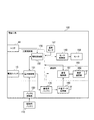
- FIG. 2 is a diagram illustrating an example of a functional block configuration of the power tool 100 according to the present embodiment.
- the power tool 100 includes a battery connection unit 120, a tool control unit 130, a motor drive unit 140, a temperature sensor 141, a motor 150, a communication unit 160, a communication battery 170, A position data acquisition unit 180.
- the battery connection section 120 is a connector that is electrically connected to the driving battery 110.
- the battery connection unit 120 transmits power supplied from the driving battery 110 to the tool control unit 130.
- a period during which the driving battery 110 is removed from the power tool 100 is referred to as a “first period”
- a period during which the driving battery 110 is attached to the power tool 100 is referred to as a “second period”.
- the tool control unit 130 controls the operation of the power tool 100.
- the tool control unit 130 includes a power control unit 131 and a drive control unit 132.
- Each of the power control unit 131 and the drive control unit 132 includes at least one processor and at least one memory.
- the tool control unit 130 includes at least one processor and at least one memory, and the functions of the power control unit 131 and the drive control unit 132 are performed by the at least one processor and at least one memory. It may be performed.
- the power control unit 131 appropriately converts the voltage of the power supplied from the driving battery 110 via the battery connection unit 120, and supplies the converted power to the drive control unit 132 and the motor drive unit 140.
- the power control unit 131 supplies power to the motor drive unit 140 when the power switch 15 is on during the period (second period) when the drive battery 110 is attached to the power tool 100, and Does not supply electric power to the motor drive unit 140 when is off.
- the power control unit 131 always supplies power to the drive control unit 132 during the second period, so that the drive control unit 132 may wait in the sleep state even when the power switch 15 is in the off state.
- the power control unit 131 detects the remaining amount of the driving battery 110 and manages remaining amount data of the driving battery 110 (driving battery remaining amount).
- the power control unit 131 notifies the communication unit 160 of the latest remaining amount of the driving battery in response to an inquiry from the communication unit 160.
- the power control unit 131 performs charging control for charging the communication battery 170 with power supplied from the driving battery 110 during a period (second period) in which the driving battery 110 is attached to the power tool 100. . Specifically, the power control unit 131 performs charging control in the non-use state in which the power tool 100 is not used during the second period. The power control unit 131 may charge the communication battery 170 to full charge or charge the communication battery 170 to a preset target value by charging control.
- the non-use state includes the power-off state of the power tool 100 (that is, the state in which the power switch 15 is set to off).
- the power control unit 131 charges the communication battery 170 in the power-off state of the power tool 100 during the second period.
- the non-use state may include a trigger lock state in which the trigger lock 16 is set to the lock state.
- the power control unit 131 may charge the communication battery 170 in the trigger lock state during the second period.
- the drive control unit 132 controls the drive of the motor 150.
- the drive control unit 132 responds to the pressing of the trigger 14 by pressing down the motor.
- the motor driving unit 140 is controlled to drive the motor 150.
- the motor 150 is driven by the motor driving unit 140, and the binding unit 11 performs a binding operation.
- the drive control unit 132 manages operation count data indicating the number of times of performing the binding operation and tool state data indicating the state of the power tool 100.
- the drive control unit 132 notifies the communication unit 160 of the latest operation count data and the latest tool state data in response to an inquiry from the communication unit 160.
- the drive control unit 132 manages the temperature data detected by the temperature sensor 141, and notifies the communication unit 160 of the latest temperature data in response to an inquiry from the communication unit 160.
- the temperature sensor 141 is a sensor that detects the temperature of the power tool 100 (for example, the temperature of the motor driving unit 140 or the motor 150).
- the motor drive unit 140 drives the motor 150 by supplying drive power to the motor 150 under the control of the drive control unit 132.
- the communication unit 160 transmits data on the power tool 100 to the management server 300.
- the communication unit 160 includes a communication control unit 161 and a wireless communication unit 162.
- the communication control unit 161 includes at least one processor and at least one memory. Note that at least one processor and at least one memory included in the communication control unit 161 may share part or all of at least one processor and at least one memory included in the tool control unit 130.
- the communication control unit 161 periodically inquires the tool control unit 130 and acquires the number of times of operation data, tool state data, remaining battery power data for driving, and temperature data from the tool control unit 130.
- the communication control unit 161 controls the wireless communication unit 162 to periodically transmit the acquired data.
- the communication control unit 161 manages communication battery remaining amount data indicating the remaining amount of the communication battery 170, and controls the wireless communication unit 162 to periodically transmit the communication battery remaining amount data. Further, the communication control unit 161 controls the wireless communication unit 162 to periodically transmit the position data acquired by the position data acquisition unit 180.
- the communication control unit 161 causes the wireless communication unit 162 to transmit the communication battery remaining amount data and the position data acquired by the position data acquisition unit 180 to the management server 300 at least in the first period. Control.
- the communication control unit 161 may control the wireless communication unit 162 to transmit the communication battery remaining amount data and the position data to the management server 300 also in the second period.
- the communication control unit 161 may control the wireless communication unit 162 to transmit the operation count data, the tool state data, the driving battery remaining amount data, and the temperature data to the management server 300 only in the second period. For example, during the second period, the communication control unit 161 performs the operation count data, the tool state data, and the driving battery only when the power of the power tool 100 is on (that is, the power switch 15 is set to on).
- the wireless communication unit 162 may be controlled to transmit the remaining amount data and the temperature data to the management server 300.
- the wireless communication unit 162 performs wireless communication using the LPWA technology.
- Radio communication section 162 converts data input from communication control section 161 into a radio signal, and transmits the radio signal to base station 210.
- the communication battery 170 supplies power to the communication unit 160 at least in the first period.
- the communication battery 170 may supply power to the communication unit 160 also in the second period.
- the power tool 100 may supply the power from the driving battery 110 to the communication unit 160 in the second period.
- the capacity of the communication battery 170 is smaller than the capacity of the drive battery 110. That is, a small-capacity battery is used as the communication battery 170.
- a secondary battery may be used as the communication battery 170, and for example, a lithium ion battery can be used.
- the position data acquisition unit 180 acquires position data indicating the geographical position of the power tool 100.
- the position data acquisition unit 180 includes a GNSS (Global Navigation Satellite Network System) receiver.
- the GNSS receiver is, for example, a GPS receiver.
- the position data acquisition unit 180 outputs the acquired position data to the communication control unit 161 under the control of the communication control unit 161.
- the position data acquisition unit 180 includes, for example, GLONASS (Global Navigation Satellite System), IRNSS (Indian Regional Navigation Satellite Satellite System), COMPASS, Galileo, or quasi-Zelite Satellite System as a GNSS receiver. May be included. Further, the position data acquisition unit 180 may be configured by a plurality of GNSS receivers.
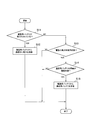
- FIG. 3 is a flowchart illustrating an example of a flow of charge / discharge control of the communication battery 170 according to the present embodiment.
- step S11 the tool control unit 130 (the power control unit 131) checks whether or not the driving battery 110 has been removed from the power tool 100. If the driving battery 110 has been removed from the power tool 100 (step S11: YES), the tool control unit 130 (power control unit 131) discharges the communication battery 170 in step S12, Power is supplied from 170 to the communication unit 160.
- step S13 the tool control unit 130 (the power control unit 131) determines whether the power tool 100 is in the non-use state. Confirm. The tool control unit 130 (the power control unit 131) may determine that the power tool 100 is in the non-use state when the power switch 15 is in the off state. The tool control unit 130 (power control unit 131) determines that the power tool 100 is not in use even when the power switch 15 is on and the trigger lock 16 is set to the locked state. Is also good. When the power tool 100 is in the use state (step S13: NO), this flow ends without charging the communication battery 170.
- step S14 the tool control unit 130 (the power control unit 131) checks whether the remaining amount of the communication battery 170 is less than the threshold. I do. This threshold may be set to a value smaller than the value indicating the full charge of the communication battery 170. Note that the tool control unit 130 (the power control unit 131) may detect the remaining amount of the communication battery 170. Alternatively, the communication unit 160 (the communication control unit 161) detects the remaining amount of the communication battery 170, and notifies the tool control unit 130 (the power control unit 131) of the detected remaining amount from the communication unit 160 (the communication control unit 161). May be done.
- the communication unit 160 (the communication control unit 161) checks whether or not the remaining amount of the communication battery 170 is less than the threshold, and notifies the communication unit 160 (the communication control unit 161) of the confirmation result or the request for charging the communication battery 170. ) May be notified to the tool control unit 130 (power control unit 131).
- the remaining amount of the communication battery 170 is equal to or larger than the threshold (step S14: NO)
- this flow ends without charging the communication battery 170.
- the threshold used in step S14 may be set according to the temperature detected by the temperature sensor 141.
- the tool control unit 130 power control unit 131) or the communication unit 160 (Communication control unit 161) sets the threshold used in step S14 high in accordance with the high temperature detected by temperature sensor 141. This makes it difficult for the communication battery 170 to be charged at a high temperature, so that deterioration of the communication battery 170 is easily suppressed.
- step S14 If the remaining amount of the communication battery 170 is less than the threshold value (step S14: YES), the tool control unit 130 (power control unit 131) uses the power supplied from the drive battery 110 in step S15. Charge control to charge the battery.
- step S23 and step S24 may be reversed.
- the power tool 100 is driven by electric power supplied from a detachable driving battery 110.
- the power tool 100 includes a communication unit 160 that transmits data related to the power tool 100 to the management server 300 and a communication unit that supplies power to the communication unit 160 during a first period in which the driving battery 110 is removed from the power tool 100.
- a tool control unit 130 power control
- a tool control unit 130 performs charging control for charging the communication battery 170 with power supplied from the driving battery 110 Unit 131).
- the communication battery 170 supplies power to the communication unit 160 in the first period. Since the communication unit 160 can transmit data on the power tool 100 to the management server 300, the management server 300 can easily perform appropriate management.
- the communication battery 170 is charged by the power supplied from the driving battery 110, so that the communication battery 170 is separately charged by the user. Since there is no need to do so, the communication battery 170 can be charged with less trouble for the user.
- the tool control unit 130 controls the charging in a non-use state in which the power tool 100 is not used. I do. Thereby, the adverse effect on the motor drive of the motor drive unit 140 is reduced, and the communication battery 170 can be charged with the power supplied from the drive battery 110.
- the communication battery 170 is constantly charged in the second period, there is a concern that the deterioration of the driving battery 110 may progress.
- the communication battery 170 is charged only during the non-use state in which the power tool 100 is not used during the second period, so that the deterioration of the communication battery 170 is easily suppressed.
- the tool control unit 130 when the remaining amount of the communication battery 170 is less than the threshold, the tool control unit 130 (the power control unit 131) performs charge control in a non-use state.
- This makes it easy to charge the communication battery 170 at an appropriate timing, for example, at a timing when the remaining amount of the communication battery 170 is low. Therefore, it is easy to suppress deterioration due to frequent charging of the communication battery 170, and it is difficult for the communication battery 170 to be overcharged.
- this threshold value in accordance with the temperature detected by the temperature sensor 141, it is possible to make the communication battery 170 difficult to be charged at a high temperature, so that the deterioration of the communication battery 170 is further suppressed. It's easy to do.
- the capacity of the communication battery 170 is smaller than the capacity of the drive battery 110. That is, a small-capacity battery is used as the communication battery 170. Accordingly, even when the communication battery 170 is provided, it is easy to suppress an increase in the cost of the power tool 100.
- the power tool 100 includes a position data acquisition unit 180 that acquires position data indicating a geographical position of the power tool 100.
- the communication unit 160 transmits the position data acquired by the position data acquisition unit 180 to the management server 300 at least in the first period. Accordingly, even when the driving battery 110 is removed, the management server 300 can easily grasp the geographical position of the power tool 100 based on the position data. Therefore, when the power tool 100 is lost or the power tool 100 is stolen, the management server 300 can easily specify the current position of the power tool 100.
- the communication unit 160 transmits the communication battery remaining amount data to the management server 300 at least in the first period. Accordingly, even when the driving battery 110 is removed, the management server 300 can easily grasp the remaining amount of the communication battery 170 based on the remaining amount data.
- the power control unit 131 is included on the tool control unit 130 side, but a power control unit is provided in the communication unit 160, and the power control unit on the communication unit 160 side performs the power control described above. Some or all of the functions of the unit 131 may be executed. In other words, when the communication unit 160 includes the power control unit of the power tool 100, the power control unit of the communication unit 160 cooperates with the tool control unit 130 (or the power control unit 131) to operate the power control unit. Some or all of the functions of 131 may be configured to be executable.
- the driving battery 110 is charged while being removed from the power tool 100.
- the driving battery 110 may be configured to be rechargeable when attached to the power tool 100.
- the power tool 100 can be regarded as being in a non-use state.
- the tool control unit 130 determines that the remaining amount of the driving battery 110 is low.
- the charge control for the communication battery 170 may be started when the threshold value is exceeded. This gives priority to charging of the driving battery 110, waits without charging the communication battery 170 until the remaining amount of the driving battery 110 becomes sufficient, and makes the remaining amount of the driving battery 110 sufficient. Then, the charging of the communication battery 170 can be started.
- FIG. 4 is a flowchart showing an example of a flow of charge / discharge control of the communication battery 170 according to the first modification.
- steps S21 and S22 are the same as those in the above-described embodiment.
- step S23 the tool control unit 130 (the power control unit 131) determines whether the driving battery 110 is being charged. Confirm. If the driving battery 110 is not being charged (step S23: NO), this flow ends without charging the communication battery 170.
- the tool control unit 130 (the power control unit 131) checks whether the remaining amount of the driving battery 110 is equal to or greater than a threshold. When the remaining amount of the driving battery 110 is less than the threshold value (step S24: NO), the tool control unit 130 (the power control unit 131) waits until the remaining amount of the driving battery 110 becomes equal to or more than the threshold value.
- step S24 If the remaining amount of the driving battery 110 is equal to or greater than the threshold (step S24: YES), the tool control unit 130 (power control unit 131) uses the power supplied from the driving battery 110 to communicate with the communication battery 170 in step S25. Charge control to charge the battery.
- the case where the communication unit 160 cannot transmit data related to the power tool 100 to the management server 300 is not particularly considered. However, it is assumed that the power tool 100 is stolen and the communication function is restricted so that the thief does not know the position, or the communication battery 170 or the communication unit 160 is physically removed.
- the tool control unit 130 (the power control unit 131) restricts the power supply of the driving battery 110 when the communication unit 160 cannot transmit data related to the power tool 100 to the management server 300.
- the tool control unit 130 detects that the electrical connection between the tool control unit 130 and the communication unit 160 (the communication battery 170) has been disconnected
- the power tool 100 The power supply from the driving battery 110 to the drive control unit 132 and / or the motor drive unit 140 is shut off so that the power supply cannot operate.
- the possibility of the power tool 100 being stolen can be reduced.
- the communication unit 160 and the communication battery 170 are built in the power tool 100 .
- a configuration in which a communication device having the communication unit 160 and the communication battery 170 is externally attached to the power tool 100 may be adopted.
- the communication device according to the third modification is configured to be detachable from the power tool 100.
- FIG. 5 is a diagram illustrating an example of a configuration of the power tool 100 and the communication device 400 according to the third modification.
- the communication device 400 has a connection portion 191 for electrically connecting to the electric power tool 100 driven by electric power supplied from the detachable driving battery 110.
- the power tool 100 has a connection portion 192 for electrically connecting to the connection portion 191 of the communication device 400.
- the communication device 400 includes a communication unit 160 that transmits data related to the power tool 100 to the management server 300, and a communication unit that supplies power to the communication unit 160 during a first period in which the driving battery 110 is removed from the power tool 100. And a battery 170.
- the communication device 400 may further include a position data acquisition unit 180.
- the communication unit 160, the communication battery 170, and the position data acquisition unit 180 have the same configuration and functions as those in the above-described embodiment.
- the communication battery 170 is charged by the electric power supplied from the driving battery 110 via the power tool 100 during the second period in which the driving battery 110 is attached to the power tool 100.
- the communication device 400 having the communication unit 160 and the communication battery 170 as an external component of the power tool 100, the user can purchase the power tool 100 and then communicate with the power tool 100 as necessary. Functions can be added. Further, when the communication unit 160 or the communication battery 170 has failed or deteriorated over time, the communication device 400 can be easily replaced.
- FIG. 5 illustrates an example in which the power tool 100 is provided with the power control unit 131
- the power control unit is provided in the communication device 400
- the power control unit in the communication device 400 uses the power control unit described above.
- Some or all of the functions of 131 may be executed.
- the communication device 400 may include a power control unit of the power tool 100, and cooperate with the tool control unit 130 (or the power control unit 131) via the connection units (190 and 191) to perform communication.
- the power control unit of the device 400 may be configured to be able to execute some or all of the functions of the power control unit 131 described above.
- the tool control unit 130 (the power control unit 131) charges the battery in the non-use state in which the power tool 100 is not used during the second period in which the driving battery 110 is attached to the power tool 100.
- An example of performing the control has been described.
- the tool control unit 130 (the power control unit 131) may perform the charge control even in the use state in which the power tool 100 is used during the second period. In this case, step S13 in FIG. 3 may be omitted.
- the management device is the management server 300 provided on the communication network 200 and the management server 300 communicates with the power tool 100 or the communication device 400 via the communication network 200.
- the management device may directly communicate with the power tool 100 or the communication device 400 without using the communication network 200.
- a program that causes a computer to execute each process performed by the power tool 100 or the communication device 400 may be provided.
- the program may be recorded on a computer-readable medium.
- a computer readable medium it is possible to install the program on a computer.
- the computer-readable medium on which the program is recorded may be a non-transitory recording medium.
- the non-transitory recording medium is not particularly limited, but may be, for example, a recording medium such as a CD-ROM or a DVD-ROM.
Landscapes
- Engineering & Computer Science (AREA)
- Mechanical Engineering (AREA)
- Charge And Discharge Circuits For Batteries Or The Like (AREA)
- Secondary Cells (AREA)
- Portable Power Tools In General (AREA)
Abstract
電動工具(100)は、着脱可能な駆動用バッテリ(110)から供給される電力によって駆動する。電動工具(100)は、電動工具(100)に関するデータを管理装置に送信する通信部(160)と、駆動用バッテリ(110)が電動工具(100)から取り外されている第1期間において、通信部(160)に電力を供給する通信用バッテリ(170)と、駆動用バッテリ(110)が電動工具(100)に取り付けられている第2期間において、駆動用バッテリ(110)から供給される電力によって通信用バッテリ(170)を充電する充電制御を行う工具制御部(130)とを備える。
Description
本発明は、通信機能を有する電動工具及び通信装置に関する。
近年、通信機能を有する電動工具が提案されている。特許文献1に記載の電動工具は、電動工具の締付トルク、ねじ締め本数、作業時間、バッテリ残量などの情報を管理装置に送信し、管理装置側では、電動工具の状況を管理する。
一実施形態に係る電動工具は、着脱可能な駆動用バッテリから供給される電力によって駆動する電動工具である。前記電動工具は、前記電動工具に関するデータを管理装置に送信する通信部と、前記駆動用バッテリが前記電動工具から取り外されている第1期間において、前記通信部に電力を供給する通信用バッテリと、前記駆動用バッテリが前記電動工具に取り付けられている第2期間において、前記駆動用バッテリから供給される電力によって前記通信用バッテリを充電する充電制御を行う少なくとも一つの制御部とを備える。
一実施形態に係る通信装置は、着脱可能な駆動用バッテリから供給される電力によって駆動する電動工具と電気的に接続するための接続部と、前記電動工具に関するデータを管理装置に送信する通信部と、前記駆動用バッテリが前記電動工具から取り外されている第1期間において、前記通信部に電力を供給する通信用バッテリとを備える。前記通信用バッテリは、前記駆動用バッテリが前記電動工具に取り付けられている第2期間において、前記駆動用バッテリから前記電動工具を介して供給される電力によって充電される。
図面を参照して、一実施形態に係る電動工具について説明する。図面の記載において、同一又は類似の部分には同一又は類似の符号を付している。
(開示の概要)
通信機能を有する電動工具は、作業現場で使用されている状態においてデータを送信するだけではなく、倉庫などで保管されている状態においてもデータを送信可能であることが望まれる。
通信機能を有する電動工具は、作業現場で使用されている状態においてデータを送信するだけではなく、倉庫などで保管されている状態においてもデータを送信可能であることが望まれる。
しかしながら、電動工具の中には、電動工具を駆動させるための駆動用バッテリが着脱可能なタイプのものが存在する。このような電動工具は、駆動用バッテリが取り外された状態で保管される場合がある。
駆動用バッテリが電動工具から取り外されている期間においては、電動工具に電力が供給されず、電動工具からデータを送信できない。このため、電動工具から送信されるデータを管理装置が取得できず、管理装置が適切な管理を行うことができない可能性がある。
そこで、本開示は、駆動用バッテリが着脱可能に構成される場合であっても、管理装置が適切な管理を行いやすくする電動工具及び通信装置を提供する。
一実施形態に係る電動工具は、着脱可能な駆動用バッテリから供給される電力によって駆動する電動工具である。前記電動工具は、前記電動工具に関するデータを管理装置に送信する通信部と、前記駆動用バッテリが前記電動工具から取り外されている第1期間において、前記通信部に電力を供給する通信用バッテリと、前記駆動用バッテリが前記電動工具に取り付けられている第2期間において、前記駆動用バッテリから供給される電力によって前記通信用バッテリを充電する充電制御を行う少なくとも一つの制御部とを備える。
一実施形態に係る通信装置は、着脱可能な駆動用バッテリから供給される電力によって駆動する電動工具と電気的に接続するための接続部と、前記電動工具に関するデータを管理装置に送信する通信部と、前記駆動用バッテリが前記電動工具から取り外されている第1期間において、前記通信部に電力を供給する通信用バッテリとを備える。前記通信用バッテリは、前記駆動用バッテリが前記電動工具に取り付けられている第2期間において、前記駆動用バッテリから前記電動工具を介して供給される電力によって充電される。
一実施形態に係る電動工具及び通信装置によれば、駆動用バッテリが着脱可能に構成される場合であっても、管理装置が適切な管理を行いやすくすることができる。
(システム構成の一例)
図1は、本実施形態に係る電動工具管理システム1の構成の一例を示す図である。
図1は、本実施形態に係る電動工具管理システム1の構成の一例を示す図である。
図1に示すように、電動工具管理システム1は、電動工具100と、管理サーバ300とを有する。
電動工具100は、コードレス型の電動工具であり、駆動用バッテリ110(バッテリパック)から供給される電力によって駆動する装置である。駆動用バッテリ110は、電動工具100に着脱可能に構成される。駆動用バッテリ110は二次電池であればよく、例えばリチウムイオンバッテリである。駆動用バッテリ110は、電動工具100から取り外された状態において、図示を省略する充電器により充電される。
本実施形態において、電動工具100が結束機(例えば、鉄筋結束機)である一例について説明する。但し、電動工具100は、結束機以外の電動工具、例えば、電動ドリル、電動ドライバー、電動のこぎり、研削機、又は研磨機等であってもよい。
電動工具100は、結束部11と、本体部12と、グリップ部13とを有する。結束部11は、鉄筋を挟むアームを有し、アームに挟まれた鉄筋に対して本体部12から供給されるワイヤを巻き付けることにより、鉄筋の結束を行う。
本体部12は、ワイヤが巻き付けられたリールを収容する。また、本体部12は、モータ150(図2参照)を内蔵する。モータ150は、ワイヤを結束部11に供給するとともにワイヤを鉄筋に巻き付けるための駆動力を発生させる。本体部12には、電動工具100の電源オン/オフを行うための電源スイッチ15が設けられる。
グリップ部13は、本体部12から下方に向けて延びる部材であり、ユーザによって把持される。グリップ部13の上端部分には、トリガ14が設けられる。トリガ14が押し下げられることにより、結束部11及び本体部12が結束動作を行う。トリガ14をロック(固定)するトリガロック16が設けられてもよい。トリガロック16がロック状態に設定される場合、トリガ14が押し下げられないようにロックされる。グリップ部13の下端部分には、駆動用バッテリ110を着脱するためのラッチ機構が設けられる。
電動工具100は、通信機能を有する。本実施形態において、電動工具100は、LPWA(Low Power Wide Area)技術を用いた無線通信機能を有する。電動工具100は、通信ネットワーク200に含まれる基地局210との無線通信を行う。電動工具100は、上り方向のみの単方向通信を行うように構成されていてもよい。電動工具100は、通信ネットワーク200を介して、管理サーバ300にデータを送信する。
例えば、電動工具100は、作動回数データ、工具状態データ、駆動用バッテリ残量データ、温度データ、位置データ、及び通信用バッテリ残量データのうち少なくとも1つを管理サーバ300に送信する。作動回数データは、電動工具100が作動した回数(すなわち、結束動作を行った回数)を示すデータである。工具状態は、電動工具100の状態、例えばエラー状態を示すデータである。駆動用バッテリ残量データは、駆動用バッテリ110の残量を示すデータである。ここで、バッテリ残量は、容量に対する現在の残量の割合(パーセンテージ)で示されてもよい。温度データは、電動工具100の温度を示すデータである。位置データは、電動工具100の地理的な位置を示すデータである。位置データは、例えばGPS(Global Positioning System)を用いて得られる緯度経度データである。通信用バッテリ残量データは、通信用バッテリ170(図2参照)の残量を示すデータである。
通信ネットワーク200は、電動工具100との無線通信を行う基地局210を有する。通信ネットワーク200は、狭域通信網(LAN:Local Area Network)、高域通信網(WAN:Wide Area Network)、及びインターネットのうち少なくとも1つを含む。
管理サーバ300は、電動工具100を管理する管理装置の一例である。管理サーバ300は、通信ネットワーク200に接続され、通信ネットワーク200を介して電動工具100からデータを取得し、取得したデータを管理する。
(電動工具の機能ブロック構成)
図2は、本実施形態に係る電動工具100の機能ブロック構成の一例を示す図である。
図2は、本実施形態に係る電動工具100の機能ブロック構成の一例を示す図である。
図2に示すように、電動工具100は、バッテリ接続部120と、工具制御部130と、モータ駆動部140と、温度センサ141と、モータ150と、通信部160と、通信用バッテリ170と、位置データ取得部180とを有する。
バッテリ接続部120は、駆動用バッテリ110と電気的に接続されるコネクタである。バッテリ接続部120は、駆動用バッテリ110が電動工具100に取り付けられた場合に、駆動用バッテリ110から供給される電力を工具制御部130に伝達する。以下において、駆動用バッテリ110が電動工具100から取り外されている期間を「第1期間」と称し、駆動用バッテリ110が電動工具100に取り付けられている期間を「第2期間」と称する。
工具制御部130は、電動工具100の動作を制御する。工具制御部130は、電力制御部131と、駆動制御部132とを備える。電力制御部131及び駆動制御部132のそれぞれは、少なくとも1つのプロセッサ及び少なくとも1つのメモリを含んで構成される。なお、電動工具100は、工具制御部130が少なくとも1つのプロセッサ及び少なくとも1つのメモリを含んで構成され、当該少なくとも1つのプロセッサ及び少なくとも1つのメモリにより電力制御部131及び駆動制御部132の機能が実行されてもよい。
電力制御部131は、駆動用バッテリ110からバッテリ接続部120を介して供給される電力の電圧を適宜変換し、変換後の電力を駆動制御部132及びモータ駆動部140に供給する。電力制御部131は、駆動用バッテリ110が電動工具100に取り付けられている期間(第2期間)において、電源スイッチ15がオン状態にある場合にモータ駆動部140に電力を供給し、電源スイッチ15がオフ状態にある場合にモータ駆動部140に電力を供給しない。電力制御部131が第2期間において常に駆動制御部132に電力を供給することにより、駆動制御部132が、電源スイッチ15がオフ状態にある場合であってもスリープ状態で待機してもよい。
また、電力制御部131は、駆動用バッテリ110の残量を検出し、駆動用バッテリ110の残量データ(駆動用バッテリ残量)を管理する。電力制御部131は、通信部160からの問い合わせに応じて、最新の駆動用バッテリ残量を通信部160に通知する。
さらに、電力制御部131は、駆動用バッテリ110が電動工具100に取り付けられている期間(第2期間)において、駆動用バッテリ110から供給される電力によって通信用バッテリ170を充電する充電制御を行う。具体的には、電力制御部131は、第2期間のうち、電動工具100が使用されていない非使用状態において充電制御を行う。電力制御部131は、充電制御によって、通信用バッテリ170を満充電まで充電してもよいし、予め設定された目標値まで通信用バッテリ170を充電してもよい。
ここで、非使用状態は、電動工具100の電源オフ状態(すなわち、電源スイッチ15がオフに設定されている状態)を含む。電力制御部131は、第2期間のうち電動工具100の電源オフ状態において通信用バッテリ170を充電する。非使用状態は、トリガロック16がロック状態に設定されたトリガロック状態を含んでもよい。電力制御部131は、第2期間のうちトリガロック状態において通信用バッテリ170を充電してもよい。
駆動制御部132は、モータ150の駆動を制御する。駆動制御部132は、第2期間であって、且つ電動工具100の電源オン状態(すなわち、電源スイッチ15がオンに設定されている状態)において、トリガ14が押し下げられたことに応じて、モータ150を駆動させるようモータ駆動部140を制御する。その結果、モータ150がモータ駆動部140により駆動され、結束部11が結束動作を行う。
駆動制御部132は、結束動作を行った回数を示す作動回数データと、電動工具100の状態を示す工具状態データを管理する。駆動制御部132は、通信部160からの問い合わせに応じて、最新の作動回数データ及び最新の工具状態データを通信部160に通知する。また、駆動制御部132は、温度センサ141が検出した温度データを管理しており、通信部160からの問い合わせに応じて、最新の温度データを通信部160に通知する。温度センサ141は、電動工具100における温度(例えば、モータ駆動部140又はモータ150)の温度を検出するセンサである。
モータ駆動部140は、駆動制御部132の制御下で、モータ150に駆動電力を供給することにより、モータ150を駆動する。
通信部160は、電動工具100に関するデータを管理サーバ300に送信する。通信部160は、通信制御部161と、無線通信部162とを有する。通信制御部161は、少なくとも1つのプロセッサ及び少なくとも1つのメモリを含んで構成される。なお、通信制御部161を構成する少なくとも1つのプロセッサ及び少なくとも1つのメモリは、工具制御部130を構成する少なくとも1つのプロセッサ及び少なくとも1つのメモリの一部又は全部を共有してもよい。
通信制御部161は、工具制御部130に対して定期的に問い合わせを行い、作動回数データ、工具状態データ、駆動用バッテリ残量データ、及び温度データを工具制御部130から取得する。通信制御部161は、取得したデータを定期的に送信するよう無線通信部162を制御する。
また、通信制御部161は、通信用バッテリ170の残量を示す通信用バッテリ残量データを管理しており、通信用バッテリ残量データを定期的に送信するよう無線通信部162を制御する。さらに、通信制御部161は、位置データ取得部180により取得される位置データを定期的に送信するよう無線通信部162を制御する。
本実施形態において、通信制御部161は、少なくとも第1期間において、通信用バッテリ残量データと、位置データ取得部180により取得された位置データとを管理サーバ300に送信するよう無線通信部162を制御する。通信制御部161は、第2期間においても、通信用バッテリ残量データと位置データとを管理サーバ300に送信するよう無線通信部162を制御してもよい。
通信制御部161は、第2期間においてのみ、作動回数データ、工具状態データ、駆動用バッテリ残量データ、及び温度データを管理サーバ300に送信するよう無線通信部162を制御してもよい。例えば、通信制御部161は、第2期間のうち、電動工具100の電源オン状態(すなわち、電源スイッチ15がオンに設定されている状態)においてのみ、作動回数データ、工具状態データ、駆動用バッテリ残量データ、及び温度データを管理サーバ300に送信するよう無線通信部162を制御してもよい。
無線通信部162は、LPWA技術を用いた無線通信を行う。無線通信部162は、通信制御部161から入力されるデータを無線信号に変換し、無線信号を基地局210に送信する。
通信用バッテリ170は、少なくとも第1期間において通信部160に電力を供給する。通信用バッテリ170は、第2期間においても通信部160に電力を供給してもよい。或いは、電動工具100は、第2期間において、駆動用バッテリ110からの電力を通信部160に供給してもよい。
本実施形態において、通信用バッテリ170の容量は、駆動用バッテリ110の容量よりも小さい。すなわち、通信用バッテリ170として、小容量のバッテリが用いられる。なお、通信用バッテリ170としては二次電池を用いればよく、例えばリチウムイオンバッテリを用いることができる。
位置データ取得部180は、電動工具100の地理的な位置を示す位置データを取得する。位置データ取得部180は、GNSS(Global Navigation Satellite System)受信機を含んで構成される。GNSS受信機は、例えばGPS受信機である。位置データ取得部180は、通信制御部161の制御下で、取得した位置データを通信制御部161に出力する。位置データ取得部180は、例えば、GNSS受信機として、GLONASS(Global Navigation Satellite System)、IRNSS(Indian Regional Navigational Satellite System)、COMPASS、Galileo、或いは準天頂衛星システム(QZSS:Quasi-Zenith Satellites System)等の受信機を含んで構成されてよい。また位置データ取得部180は、複数のGNSS受信機により構成されてよい。
(通信用バッテリの充放電制御)
図3は、本実施形態に係る通信用バッテリ170の充放電制御のフローの一例を示すフロー図である。
図3は、本実施形態に係る通信用バッテリ170の充放電制御のフローの一例を示すフロー図である。
図3に示すように、ステップS11において、工具制御部130(電力制御部131)は、駆動用バッテリ110が電動工具100から取り外されているか否かを確認する。駆動用バッテリ110が電動工具100から取り外されている場合(ステップS11:YES)、ステップS12において、工具制御部130(電力制御部131)は、通信用バッテリ170を放電させることにより、通信用バッテリ170から通信部160に電力を供給する。
駆動用バッテリ110が電動工具100に取り付けられている場合(ステップS11:NO)、ステップS13において、工具制御部130(電力制御部131)は、電動工具100が非使用状態にあるか否かを確認する。工具制御部130(電力制御部131)は、電源スイッチ15がオフ状態にある場合に、電動工具100が非使用状態にあると判定してもよい。工具制御部130(電力制御部131)は、電源スイッチ15がオン状態であり、且つトリガロック16がロック状態に設定されている場合にも、電動工具100が非使用状態にあると判定してもよい。電動工具100が使用状態にある場合(ステップS13:NO)、通信用バッテリ170を充電することなく本フローが終了する。
電動工具100が非使用状態にある場合(ステップS13:YES)、ステップS14において、工具制御部130(電力制御部131)は、通信用バッテリ170の残量が閾値未満であるか否かを確認する。この閾値は、通信用バッテリ170の満充電を示す値よりも小さい値に設定されてもよい。なお、工具制御部130(電力制御部131)が通信用バッテリ170の残量を検出してもよい。或いは、通信部160(通信制御部161)が通信用バッテリ170の残量を検出し、検出した残量が通信部160(通信制御部161)から工具制御部130(電力制御部131)に通知されてもよい。或いは、通信用バッテリ170の残量が閾値未満であるか否かを通信部160(通信制御部161)が確認し、確認結果又は通信用バッテリ170の充電要求を通信部160(通信制御部161)から工具制御部130(電力制御部131)に通知してもよい。通信用バッテリ170の残量が閾値以上である場合(ステップS14:NO)、通信用バッテリ170を充電することなく本フローが終了する。
ステップS14において用いる閾値は、温度センサ141により検出された温度に応じて設定されてもよい。例えば、工具制御部130(電力制御部131)又は通信部160
(通信制御部161)は、温度センサ141により検出された温度が高温であることに応じて、ステップS14において用いる閾値を高く設定する。これにより、高温時おいて通信用バッテリ170が充電されにくくなるため、通信用バッテリ170の劣化を抑制しやすい。
(通信制御部161)は、温度センサ141により検出された温度が高温であることに応じて、ステップS14において用いる閾値を高く設定する。これにより、高温時おいて通信用バッテリ170が充電されにくくなるため、通信用バッテリ170の劣化を抑制しやすい。
通信用バッテリ170の残量が閾値未満である場合(ステップS14:YES)、ステップS15において、工具制御部130(電力制御部131)は、駆動用バッテリ110から供給される電力によって通信用バッテリ170を充電する充電制御を行う。
なお、本フローにおいて、ステップS23及びステップS24の順序は逆であってもよい。
(実施形態のまとめ)
本実施形態に係る電動工具100は、着脱可能な駆動用バッテリ110から供給される電力によって駆動する。電動工具100は、電動工具100に関するデータを管理サーバ300に送信する通信部160と、駆動用バッテリ110が電動工具100から取り外されている第1期間において、通信部160に電力を供給する通信用バッテリ170と、駆動用バッテリ110が電動工具100に取り付けられている第2期間において、駆動用バッテリ110から供給される電力によって通信用バッテリ170を充電する充電制御を行う工具制御部130(電力制御部131)とを備える。
本実施形態に係る電動工具100は、着脱可能な駆動用バッテリ110から供給される電力によって駆動する。電動工具100は、電動工具100に関するデータを管理サーバ300に送信する通信部160と、駆動用バッテリ110が電動工具100から取り外されている第1期間において、通信部160に電力を供給する通信用バッテリ170と、駆動用バッテリ110が電動工具100に取り付けられている第2期間において、駆動用バッテリ110から供給される電力によって通信用バッテリ170を充電する充電制御を行う工具制御部130(電力制御部131)とを備える。
このような電動工具100によれば、駆動用バッテリ110が電動工具100から取り外されている第1期間において、通信用バッテリ170が通信部160に電力を供給することにより、第1期間においても、通信部160が電動工具100に関するデータを管理サーバ300に送信できるため、管理サーバ300が適切な管理を行いやすい。
また、駆動用バッテリ110が電動工具100に取り付けられている第2期間において、駆動用バッテリ110から供給される電力によって通信用バッテリ170を充電することにより、通信用バッテリ170をユーザが別途充電しなくてもよいため、ユーザの手間が少なく通信用バッテリ170を充電できる。
本実施形態において、工具制御部130(電力制御部131)は、駆動用バッテリ110が電動工具100に取り付けられている第2期間のうち、電動工具100が使用されていない非使用状態において充電制御を行う。これにより、モータ駆動部140のモータ駆動に与える悪影響を少なくし、駆動用バッテリ110から供給される電力によって通信用バッテリ170を充電できる。また、第2期間において通信用バッテリ170を常に充電すると、駆動用バッテリ110の劣化が進行する懸念がある。本実施形態においては、第2期間のうち電動工具100が使用されていない非使用状態に限定して通信用バッテリ170を充電することにより、通信用バッテリ170の劣化を抑制しやすい。
本実施形態において、工具制御部130(電力制御部131)は、通信用バッテリ170の残量が閾値未満である場合に、非使用状態において充電制御を行う。これにより、適切なタイミング、例えば通信用バッテリ170の残量が少なったタイミングで通信用バッテリ170を充電しやすい。このため、通信用バッテリ170を頻繁に充電することによる劣化を抑制しやすく、通信用バッテリ170の過充電が発生しにくい。さらに、この閾値を、温度センサ141により検出された温度に応じて設定することにより、高温時おいて通信用バッテリ170が充電されにくくすることができるため、通信用バッテリ170の劣化をより一層抑制しやすい。
本実施形態において、通信用バッテリ170の容量は、駆動用バッテリ110の容量よりも小さい。すなわち、通信用バッテリ170として、小容量のバッテリが用いられる。これにより、通信用バッテリ170を設ける場合であっても電動工具100のコストの増大を抑制しやすい。
本実施形態において、電動工具100は、電動工具100の地理的な位置を示す位置データを取得する位置データ取得部180を備える。通信部160は、少なくとも第1期間において、位置データ取得部180により取得される位置データを管理サーバ300に送信する。これにより、駆動用バッテリ110が取り外された状態であっても管理サーバ300が電動工具100の地理的な位置を位置データに基づいて把握しやすい。よって、電動工具100が紛失したり、電動工具100が盗難にあったりしたような場合に、管理サーバ300が電動工具100の現在位置を特定しやすい。
本実施形態において、通信部160は、少なくとも第1期間において、通信用バッテリ残量データを管理サーバ300に送信する。これにより、駆動用バッテリ110が取り外された状態であっても、管理サーバ300が通信用バッテリ170の残量を残量データに基づいて把握しやすい。
ここで、図2の機能ブロックの一例では工具制御部130側に電力制御部131を含むが、通信部160内に電力制御部を設け、通信部160側の電力制御部が、上述の電力制御部131の機能の一部又は全部を実行してもよい。言い換えると、通信部160が電動工具100の電力制御部を含むとき、通信部160の電力制御部は、工具制御部130(或いは、電力制御部131)と協働して、上述の電力制御部131の機能の一部又は全部を実行可能に構成されてよい。
(変更例1)
実施形態の変更例1について説明する。
実施形態の変更例1について説明する。
上述の実施形態において、駆動用バッテリ110が、電動工具100から取り外された状態において充電される一例について説明した。しかしながら、駆動用バッテリ110は、電動工具100に取り付けられている状態において充電可能に構成されてもよい。駆動用バッテリ110が充電中である場合、電動工具100が非使用状態にあるとみなすことができる。
駆動用バッテリ110が電動工具100に取り付けられている期間(第2期間)において駆動用バッテリ110が充電される場合、工具制御部130(電力制御部131)は、駆動用バッテリ110の残量が閾値以上になったときに通信用バッテリ170への充電制御を開始してもよい。これにより、駆動用バッテリ110の充電を優先し、駆動用バッテリ110の残量が十分な量になるまで通信用バッテリ170を充電せずに待ち、駆動用バッテリ110の残量が十分な量になった際に通信用バッテリ170の充電を開始できる。
図4は、変更例1に係る通信用バッテリ170の充放電制御のフローの一例を示すフロー図である。
図4に示すように、ステップS21及びステップS22は上述の実施形態と同様である。
駆動用バッテリ110が電動工具100に取り付けられている場合(ステップS21:NO)、ステップS23において、工具制御部130(電力制御部131)は、駆動用バッテリ110が充電中であるか否かを確認する。駆動用バッテリ110が充電中でない場合(ステップS23:NO)、通信用バッテリ170を充電することなく本フローが終了する。
駆動用バッテリ110が充電中である場合(ステップS23:YES)、工具制御部130(電力制御部131)は、駆動用バッテリ110の残量が閾値以上であるか否かを確認する。駆動用バッテリ110の残量が閾値未満である場合(ステップS24:NO)、工具制御部130(電力制御部131)は、駆動用バッテリ110の残量が閾値以上になるまで待つ。
駆動用バッテリ110の残量が閾値以上である場合(ステップS24:YES)、ステップS25において、工具制御部130(電力制御部131)は、駆動用バッテリ110から供給される電力によって通信用バッテリ170を充電する充電制御を行う。
本フローにおいて、上述の実施形態と同様に、通信用バッテリ170の残量が閾値未満であるか否かを確認し、通信用バッテリ170の残量が閾値未満である場合に限り通信用バッテリ170への充電制御を行うとしてもよい。
(変更例2)
実施形態の変更例2について説明する。
実施形態の変更例2について説明する。
上述の実施形態において、電動工具100に関するデータを通信部160が管理サーバ300に送信できない場合について特に考慮していなかった。しかしながら、電動工具100が盗難にあい窃盗者が位置を知られないように通信機能に制限をかけたり、通信用バッテリ170又は通信部160が物理的に取り外されたりするケースが想定される。
変更例2において、工具制御部130(電力制御部131)は、電動工具100に関するデータを通信部160が管理サーバ300に送信できない場合、駆動用バッテリ110の電力供給を制限する。例えば、工具制御部130(電力制御部131)は、工具制御部130と通信部160(通信用バッテリ170)との間の電気的な接続が切断されたことを検知した場合に、電動工具100が作動できなくなるように、駆動用バッテリ110から駆動制御部132及び/又はモータ駆動部140への電力供給を遮断する。このような機能を付加することにより、電動工具100の盗難の可能性を下げることができる。
(変更例3)
実施形態の変更例3について説明する。
実施形態の変更例3について説明する。
上述の実施形態において、通信部160及び通信用バッテリ170が電動工具100に内蔵される一例について説明した。しかしながら、通信部160及び通信用バッテリ170を有する通信装置を電動工具100の外付けとする構成であってもよい。変更例3に係る通信装置は、電動工具100に着脱可能に構成される。
図5は、変更例3に係る電動工具100及び通信装置400の構成の一例を示す図である。
図5に示すように、通信装置400は、着脱可能な駆動用バッテリ110から供給される電力によって駆動する電動工具100と電気的に接続するための接続部191を有する。一方、電動工具100は、通信装置400の接続部191と電気的に接続するための接続部192を有する。
通信装置400は、電動工具100に関するデータを管理サーバ300に送信する通信部160と、駆動用バッテリ110が電動工具100から取り外されている第1期間において、通信部160に電力を供給する通信用バッテリ170とを有する。通信装置400は、位置データ取得部180をさらに有していてもよい。通信部160、通信用バッテリ170、及び位置データ取得部180は、上述の実施形態と同様な構成及び機能を有する。
変更例3において、通信用バッテリ170は、駆動用バッテリ110が電動工具100に取り付けられている第2期間において、駆動用バッテリ110から電動工具100を介して供給される電力によって充電される。
このように、通信部160及び通信用バッテリ170を有する通信装置400を電動工具100の外付けの構成とすることにより、ユーザが電動工具100を購入した後、必要に応じて電動工具100に通信機能を付加することができる。また、通信部160又は通信用バッテリ170が故障又は経年劣化した際に通信装置400を容易に交換しやすい。
なお、図5では電動工具100側に電力制御部131を備えている一例を示したが、通信装置400側に電力制御部を設け、通信装置400側の電力制御部が、上述の電力制御部131の機能の一部又は全部を実行してもよい。言い換えると、通信装置400は、電動工具100の電力制御部を有してよく、工具制御部130(或いは、電力制御部131)と接続部(190及び191)を介して協働して、通信装置400側の電力制御部が上述の電力制御部131の機能の一部又は全部を実行可能に構成されてよい。
(その他の実施形態)
上述の実施形態において、工具制御部130(電力制御部131)が、駆動用バッテリ110が電動工具100に取り付けられている第2期間のうち、電動工具100が使用されていない非使用状態において充電制御を行う一例について説明した。しかしながら、工具制御部130(電力制御部131)は、第2期間のうち、電動工具100が使用されている使用状態においても充電制御を行ってもよい。この場合、図3のステップS13を省略してもよい。
上述の実施形態において、工具制御部130(電力制御部131)が、駆動用バッテリ110が電動工具100に取り付けられている第2期間のうち、電動工具100が使用されていない非使用状態において充電制御を行う一例について説明した。しかしながら、工具制御部130(電力制御部131)は、第2期間のうち、電動工具100が使用されている使用状態においても充電制御を行ってもよい。この場合、図3のステップS13を省略してもよい。
上述の実施形態において、管理装置が通信ネットワーク200上に設けられた管理サーバ300であり、管理サーバ300が通信ネットワーク200を介して電動工具100又は通信装置400との通信を行う一例について説明した。しかしながら、無線通信機能を有する管理装置を用いる場合、管理装置は、通信ネットワーク200を介さずに直接的に電動工具100又は通信装置400との通信を行ってもよい。
電動工具100又は通信装置400が行う各処理をコンピュータに実行させるプログラムが提供されてもよい。プログラムは、コンピュータ読取り可能媒体に記録されていてもよい。コンピュータ読取り可能媒体を用いれば、コンピュータにプログラムをインストールすることが可能である。ここで、プログラムが記録されたコンピュータ読取り可能媒体は、非一過性の記録媒体であってもよい。非一過性の記録媒体は、特に限定されるものではないが、例えば、CD-ROMやDVD-ROM等の記録媒体であってもよい。
以上、図面を参照して本実施形態について詳しく説明したが、具体的な構成は上述のものに限られることはなく、要旨を逸脱しない範囲内において様々な設計変更等をすることが可能である。また、上述した実施形態及び変更例は、相互に矛盾しない限り組み合わせて適用可能である。そして、例示されていない無数の変更例が、この開示の範囲から外れることなく想定され得るものと解される。
本願は日本国特許出願第2018-139013号(平成30年7月25日出願)の優先権を主張し、その内容のすべてが参照により本願明細書に組み込まれている。
Claims (11)
- 着脱可能な駆動用バッテリから供給される電力によって駆動する電動工具であって、
前記電動工具に関するデータを管理装置に送信する通信部と、
前記駆動用バッテリが前記電動工具から取り外されている第1期間において、前記通信部に電力を供給する通信用バッテリと、
前記駆動用バッテリが前記電動工具に取り付けられている第2期間において、前記駆動用バッテリから供給される電力によって前記通信用バッテリを充電する充電制御を行う少なくとも一つの制御部と、を備える
電動工具。 - 前記少なくとも一つの制御部は、前記第2期間のうち前記電動工具が使用されていない非使用状態において前記充電制御を行う
請求項1に記載の電動工具。 - 前記非使用状態は、前記電動工具の電源オフ状態を含む
請求項2に記載の電動工具。 - 前記少なくとも一つの制御部は、前記通信用バッテリの残量が閾値未満である場合に、前記非使用状態において前記充電制御を行う
請求項2又は3に記載の電動工具。 - 当該電動工具における温度を検出する温度センサをさらに備え、
前記少なくとも一つの制御部は、前記温度センサにより検出された前記温度に応じて前記閾値を設定する
請求項4に記載の電動工具。 - 前記通信用バッテリの容量は、前記駆動用バッテリの容量よりも小さい
請求項1乃至5のいずれか1項に記載の電動工具。 - 前記電動工具の地理的な位置を示す位置データを取得する位置データ取得部をさらに備え、
前記通信部は、少なくとも前記第1期間において、前記位置データ取得部により取得される前記位置データを前記管理装置に送信する
請求項1乃至6のいずれか1項に記載の電動工具。 - 前記通信部は、少なくとも前記第1期間において、前記通信用バッテリの残量データを前記管理装置に送信する
請求項1乃至7のいずれか1項に記載の電動工具。 - 前記第2期間において前記駆動用バッテリが充電される場合、前記少なくとも一つの制御部は、前記駆動用バッテリの残量が閾値以上になったときに前記充電制御を開始する
請求項1乃至8のいずれか1項に記載の電動工具。 - 前記少なくとも一つの制御部は、前記電動工具に関するデータを管理装置に送信できない場合、前記駆動用バッテリの電力供給を制限する
請求項1乃至9のいずれか1項に記載の電動工具。 - 着脱可能な駆動用バッテリから供給される電力によって駆動する電動工具と電気的に接続するための接続部と、
前記電動工具に関するデータを管理装置に送信する通信部と、
前記駆動用バッテリが前記電動工具から取り外されている第1期間において、前記通信部に電力を供給する通信用バッテリと、を備え、
前記通信用バッテリは、前記駆動用バッテリが前記電動工具に取り付けられている第2期間において、前記駆動用バッテリから前記電動工具を介して供給される電力によって充電される
通信装置。
Applications Claiming Priority (2)
| Application Number | Priority Date | Filing Date | Title |
|---|---|---|---|
| JP2018139013A JP2020015125A (ja) | 2018-07-25 | 2018-07-25 | 電動工具及び通信装置 |
| JP2018-139013 | 2018-07-25 |
Publications (1)
| Publication Number | Publication Date |
|---|---|
| WO2020021728A1 true WO2020021728A1 (ja) | 2020-01-30 |
Family
ID=69182313
Family Applications (1)
| Application Number | Title | Priority Date | Filing Date |
|---|---|---|---|
| PCT/JP2018/034339 Ceased WO2020021728A1 (ja) | 2018-07-25 | 2018-09-18 | 電動工具及び通信装置 |
Country Status (2)
| Country | Link |
|---|---|
| JP (1) | JP2020015125A (ja) |
| WO (1) | WO2020021728A1 (ja) |
Cited By (2)
| Publication number | Priority date | Publication date | Assignee | Title |
|---|---|---|---|---|
| JP2023155042A (ja) * | 2022-04-08 | 2023-10-20 | マックス株式会社 | 電動工具 |
| CN117396310A (zh) * | 2021-07-20 | 2024-01-12 | 喜利得股份公司 | 动力工具与可充电电池之间的通信 |
Families Citing this family (1)
| Publication number | Priority date | Publication date | Assignee | Title |
|---|---|---|---|---|
| JP2023155048A (ja) | 2022-04-08 | 2023-10-20 | マックス株式会社 | 電動工具の制御装置、電動工具、制御方法、及びプログラム |
Citations (4)
| Publication number | Priority date | Publication date | Assignee | Title |
|---|---|---|---|---|
| JP2013066949A (ja) * | 2011-09-20 | 2013-04-18 | Panasonic Eco Solutions Power Tools Co Ltd | 電動工具 |
| US20140240125A1 (en) * | 2013-02-22 | 2014-08-28 | Milwaukee Electric Tool Corporation | Wireless tracking of power tools and related devices |
| JP2014529320A (ja) * | 2011-07-24 | 2014-11-06 | 株式会社マキタ | 動力工具用アダプタ、動力工具システム及びそれを動作させる方法 |
| JP2017225225A (ja) * | 2016-06-14 | 2017-12-21 | 株式会社豊田自動織機 | 充電率推定装置 |
-
2018
- 2018-07-25 JP JP2018139013A patent/JP2020015125A/ja active Pending
- 2018-09-18 WO PCT/JP2018/034339 patent/WO2020021728A1/ja not_active Ceased
Patent Citations (4)
| Publication number | Priority date | Publication date | Assignee | Title |
|---|---|---|---|---|
| JP2014529320A (ja) * | 2011-07-24 | 2014-11-06 | 株式会社マキタ | 動力工具用アダプタ、動力工具システム及びそれを動作させる方法 |
| JP2013066949A (ja) * | 2011-09-20 | 2013-04-18 | Panasonic Eco Solutions Power Tools Co Ltd | 電動工具 |
| US20140240125A1 (en) * | 2013-02-22 | 2014-08-28 | Milwaukee Electric Tool Corporation | Wireless tracking of power tools and related devices |
| JP2017225225A (ja) * | 2016-06-14 | 2017-12-21 | 株式会社豊田自動織機 | 充電率推定装置 |
Cited By (3)
| Publication number | Priority date | Publication date | Assignee | Title |
|---|---|---|---|---|
| CN117396310A (zh) * | 2021-07-20 | 2024-01-12 | 喜利得股份公司 | 动力工具与可充电电池之间的通信 |
| JP2023155042A (ja) * | 2022-04-08 | 2023-10-20 | マックス株式会社 | 電動工具 |
| JP7818181B2 (ja) | 2022-04-08 | 2026-02-20 | マックス株式会社 | 電動工具 |
Also Published As
| Publication number | Publication date |
|---|---|
| JP2020015125A (ja) | 2020-01-30 |
Similar Documents
| Publication | Publication Date | Title |
|---|---|---|
| US11409647B2 (en) | Universal protocol for power tools | |
| WO2020021728A1 (ja) | 電動工具及び通信装置 | |
| JP5641727B2 (ja) | 充電情報表示用携帯機および充電情報表示システム | |
| CN114845839A (zh) | 用于动力工具的可插入无线通信设备 | |
| KR101254875B1 (ko) | 배터리 팩 관리시스템 | |
| KR101868175B1 (ko) | 무선 통신 장치를 가진 휴대용 전력 도구 | |
| EP3418003B1 (en) | Fastening tool | |
| CN107073696B (zh) | 用于工具机的可切换的接口 | |
| JP2006218575A (ja) | 電動工具 | |
| JP2020023026A (ja) | 工具、通信装置、工具システム及び通信方法 | |
| CN110235335A (zh) | 蓄电池管理系统、移动体、蓄电池及蓄电池管理方法 | |
| WO2020031395A1 (ja) | 工具及び通信装置 | |
| JPWO2009057187A1 (ja) | 充電システム、処理装置及び給電装置 | |
| WO2021009813A1 (ja) | 工具、電子機器、及びプログラム | |
| WO2020070823A1 (ja) | 工具管理装置、工具管理システム、工具管理方法、及び工具 | |
| US10758438B2 (en) | Mobility vehicle, mobility vehicle maintenance system, and server unit | |
| JP2023087488A (ja) | バッテリを含む電動車両を充電するためのシステム及び方法 | |
| WO2020217493A1 (ja) | 情報処理装置、情報処理方法、及び情報処理プログラム | |
| JP5384865B2 (ja) | ポートを介して双方向に電力を伝達可能な電子機器およびその動作方法 | |
| WO2020129139A1 (ja) | 工具、通信装置、及び方法 | |
| JP2023155048A (ja) | 電動工具の制御装置、電動工具、制御方法、及びプログラム | |
| JP2023087489A (ja) | バッテリを含む電動車両を充電するためのシステム及び方法 | |
| WO2020194487A1 (ja) | 工具及び通信装置 | |
| US11031811B2 (en) | Auxiliary energy circuit for battery-powered power tool | |
| WO2021009812A1 (ja) | 工具 |
Legal Events
| Date | Code | Title | Description |
|---|---|---|---|
| 121 | Ep: the epo has been informed by wipo that ep was designated in this application |
Ref document number: 18927633 Country of ref document: EP Kind code of ref document: A1 |
|
| NENP | Non-entry into the national phase |
Ref country code: DE |
|
| 122 | Ep: pct application non-entry in european phase |
Ref document number: 18927633 Country of ref document: EP Kind code of ref document: A1 |