WO2020016992A1 - 挿入装置 - Google Patents
挿入装置 Download PDFInfo
- Publication number
- WO2020016992A1 WO2020016992A1 PCT/JP2018/027093 JP2018027093W WO2020016992A1 WO 2020016992 A1 WO2020016992 A1 WO 2020016992A1 JP 2018027093 W JP2018027093 W JP 2018027093W WO 2020016992 A1 WO2020016992 A1 WO 2020016992A1
- Authority
- WO
- WIPO (PCT)
- Prior art keywords
- peripheral surface
- base member
- shielding
- tubular member
- longitudinal axis
- Prior art date
- Legal status (The legal status is an assumption and is not a legal conclusion. Google has not performed a legal analysis and makes no representation as to the accuracy of the status listed.)
- Ceased
Links
Images





Classifications
-
- A—HUMAN NECESSITIES
- A61—MEDICAL OR VETERINARY SCIENCE; HYGIENE
- A61B—DIAGNOSIS; SURGERY; IDENTIFICATION
- A61B1/00—Instruments for performing medical examinations of the interior of cavities or tubes of the body by visual or photographical inspection, e.g. endoscopes; Illuminating arrangements therefor
Definitions
- the present invention relates to an insertion device provided with a rotation mechanism.
- Patent Document 1 describes an endoscope apparatus provided with a medical rotation mechanism that rotates around a longitudinal axis in an insertion portion.
- Patent Document 2 discloses an insertion device provided with a rotary tubular member for rotating a spiral fin in an insertion portion.
- the rotation performance of the rotary tubular member with respect to the insertion portion is ensured, and the inflow of the liquid from the outside to the inside of the insertion portion is effectively prevented.
- an object of the present invention is to provide an insertion device that ensures rotation performance of a rotary tubular member with respect to an insertion portion and that appropriately prevents liquid from flowing into the insertion portion.
- the insertion device is formed integrally with an insertion portion main body extending along a longitudinal axis and a part of the insertion portion main body, and communicates with an external space of the insertion portion main body.
- a base member for defining a driving member arrangement space, a rotating tubular member arranged on the outer periphery of the base member, and a drive arranged in the driving member arrangement space for rotating the rotating tubular member about the longitudinal axis.
- a member a shielding portion formed in a gap between the base member and the rotary cylindrical member, and a pipe capable of transporting a fluid to the shielding portion, wherein the shielding portion includes the base member and the rotary cylinder. It is a space formed in a gap with the shape member, and is maintained at a high pressure by the fluid transported from the pipe.
- the shielding portion includes a ring-shaped support member disposed on an outer periphery of the base member, and an outer periphery of the base member and the support member.
- a ring-shaped seal member disposed closer to the end than the member, wherein the shielding portion is an outer peripheral surface of the base member, an inner peripheral surface of the rotary tubular member, the support member, and It may be a space surrounded by the seal member.
- the seal member is formed of a material having elasticity, and an outer peripheral surface of the base member and an inner peripheral surface of the rotary cylindrical member. It may contact the peripheral surface without any gap.
- the seal member has a gap on at least one of an outer peripheral surface of the base member and an inner peripheral surface of the rotary tubular member.
- the part of the fluid transported to the shielding part may be discharged to the outside from the gap.
- At least one of an outer peripheral surface of the base member and an inner peripheral surface of the rotary tubular member is provided with the seal.
- the vicinity of the member may be water-repellent.
- the rotation performance of the rotary tubular member with respect to the insertion portion can be ensured, and the inflow of liquid into the insertion portion can be suitably prevented.
- FIG. 3 is a cross-sectional view taken along a line AA perpendicular to a longitudinal axis of the insertion portion shown in FIG. 2.
- FIG. 3 is a cross-sectional view taken along a line BB perpendicular to a longitudinal axis of the insertion portion shown in FIG. 2. It is the perspective view which looked at the 1st support member of the rotation mechanism of the same insertion part from the tip side. It is the perspective view which looked at the 1st support member of the rotation mechanism from the base end side.
- FIG. 1 is a diagram showing a conceptual external configuration of an endoscope device 100 which is an insertion device according to the present embodiment.
- an endoscope device (insertion device) 100 includes an insertion unit 2 inserted into a lumen of a living body, and an operation unit 3 provided on a proximal end side of the insertion unit 2. .
- the insertion section 2 includes a long insertion section main body 4 extending along the longitudinal axis C of the insertion section 2, and a bending section 5 provided on the distal end side of the insertion section main body 4. , A living body insertion mechanism 6 and a rotation mechanism 10.
- the insertion section 2 is centered on the longitudinal axis C, and is inserted into a body cavity when the endoscope device 100 is used.
- the bending portion 5 is a long member that bends in accordance with the bending of the lumen.
- An imaging unit (not shown) is provided at the distal end 5 a of the bending unit 5.
- the in-vivo insertion mechanism 6 is a cylindrical member that fits on the outer circumference of the insertion portion main body 4 or the bending portion 5 with a gap therebetween, and is detachably attached to the rotation mechanism 10.
- the in-vivo insertion mechanism 6 has a fin 7 functioning as a propulsion site and a retraction site, and a spiral tube (introduction propulsion unit) 9 that rotates about a longitudinal axis and functions as introduction propulsion.
- the fin 7 is spirally wound around the outer periphery of the spiral tube 9.
- the living body insertion mechanism 6 advances in the lumen.
- the living body insertion mechanism 6 is retracted in the lumen.
- the spiral tube 9 has a material (for example, a rubber material or a resin material) or a structure having flexibility according to the bending of the bending portion 5.
- the tip side of the spiral tube 9 is formed in a tapered shape, so that it can be easily inserted into a lumen.
- the in-vivo insertion mechanism 6 is a disposable product (disposable product) that is detachably attached to the rotation mechanism 10 and can be replaced for each treatment to prevent infection.
- the rotation mechanism 10 rotates the spiral tube 9 about the longitudinal axis of the insertion section 2 to assist in introducing the insertion section 2 into the lumen.
- the rotation mechanism 10 can rotate the spiral tube 9 in both directions (CW, CCW).
- the rotation mechanism 10 has a first end of a shaft 13 inserted through the inside of the insertion section 2 connected thereto, and a second end of the shaft 13 connected to a motor (not shown) provided on the operation section 3.
- the motor rotates the shaft 13 about the longitudinal axis, and rotates a part of the rotation mechanism 10.
- the operation unit 3 includes an operation knob 30 and a switch 31 for performing various operations including the bending operation of the bending unit 5 and the rotation of the rotation mechanism 10.
- the operating section 3 is provided with a treatment instrument insertion section 32 for inserting a treatment instrument.
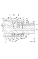
- FIG. 2 is a cross-sectional view of the insertion section 2 in the direction of the longitudinal axis C.
- FIG. 3 is a sectional view taken along the line AA perpendicular to the longitudinal axis C of the insertion section 2 shown in FIG.
- FIG. 4 is a cross-sectional view taken along a line BB perpendicular to the longitudinal axis C of the insertion section 2 shown in FIG.
- the AA section and the BB section are also referred to as an XY plane
- the direction of the longitudinal axis C of the insertion section 2 is also referred to as a Z-axis direction.
- the insertion portion 2 is provided with a plurality of channels 20 which are passages (internal cavities) extending from the distal end portion 5a to the entire length of the insertion portion 2.
- channels 20 which are passages (internal cavities) extending from the distal end portion 5a to the entire length of the insertion portion 2.
- a curved wire 21 As shown in FIGS. 3 and 4, inside the insertion portion 2, a curved wire 21, an imaging cable 22, a light guide 23, a treatment instrument channel 24, an air supply channel 25, a water supply channel 26, The fluid pipe 27 extends along the longitudinal axis C.
- the four bending wires 21 are provided, and bend the bending portion 5 in four directions.
- the proximal end of the bending wire 21 is connected to the operation knob 30 of the operation unit 3.
- the distal end of the bending wire 21 is connected to the distal end 5 a of the bending section 5.
- the bending wire 21 is pulled by the bending operation using the operation knob 30, and the bending portion 5 is bent.
- the imaging cable 22 is connected to an imaging unit provided at the tip 5 a of the bending unit 5.
- the imaging cable 22 extends through the inside of the insertion section 2 and the inside of the operation section 3, and is connected to a peripheral unit having an image processing function.
- the light guide 23 is connected to the light source at the base end.
- the light emitted from the light source is guided by the light guide 23, and is emitted to the subject from the tip 5 a of the curved portion 5.
- the treatment instrument channel 24 is a channel into which a treatment instrument such as a grasping forceps is inserted.
- the treatment tool channel 24 has a proximal end connected to the treatment tool insertion section 32 through the inside of the insertion section 2 and the inside of the operation section 3.
- the treatment tool inserted from the treatment tool insertion portion 32 passes through the inside of the treatment tool channel 24 and protrudes from the opening of the distal end portion 5a of the curved portion 5 toward the distal direction.
- the air supply channel 25 is connected to the pump at the base end, and discharges air supplied from the pump from the nozzle at the distal end portion 5 a of the bending portion 5 based on the operation of the switch 31 of the operation section 3.
- the discharged air removes, for example, an adhering substance attached to the distal end portion 5a, or inflates the intestinal tract by feeding air during an endoscopic examination.
- the water supply channel 26 is connected to the water supply tank at the base end, and discharges water supplied from the water supply tank from the nozzle at the distal end portion 5 a of the bending portion 5 based on the operation of the switch 31 of the operation section 3.
- the discharged water removes, for example, dirt attached to the distal end portion 5a or cleans the subject.
- the fluid pipe (fluid supply unit) 27 is connected to the pump at the base end, and supplies air sent from the pump to the shielding unit 15 described later.
- the pump to which the fluid pipe 27 is connected may be the same as the pump to which the air supply channel 25 is connected, or may be another pump.
- the rotation mechanism 10 includes a base member 11, a rotary tubular member 12, a driving member 14, a shielding part 15, a pipe 18, and a spacer 19.
- the base member 11 is formed integrally with a part of the insertion portion main body 4. Since the base member 11 is a part of the insertion portion main body 4, the longitudinal axis C is the axis center.
- the base member 11 defines a driving member arrangement space 11 s having an opening 11 a communicating with the external space of the insertion portion main body 4.
- the driving member 14 is arranged in the driving member arrangement space 11s.
- the rotating tubular member 12 is a tubular member arranged on the outer periphery of the insertion section main body 4.
- the rotary tubular member 12 is arranged at a position covering the driving member arrangement space 11s.
- the rotary tubular member 12 is rotatable with respect to the insertion portion main body 4 in a direction around a longitudinal axis.
- the proximal end of the spiral tube 9 is in close contact with the outer peripheral portion of the rotary tubular member 12. Thereby, the spiral tube 9 is fixed to the rotary tubular member 12, and the spiral tube 9 rotates integrally with the rotary tubular member 12 in the direction around the longitudinal axis.
- the drive member 14 is disposed in the drive member arrangement space 11s, and the first end of the shaft 13 is connected.
- the drive member 14 is driven by rotation about the longitudinal axis of the shaft 13 and rotates the rotary tubular member 12 in a direction around the longitudinal axis.
- An external gear 14 g is provided on the outer periphery of the driving member 14.
- An internal gear 12g that meshes with the external gear 14g is provided on the inner peripheral portion of the rotary tubular member 12.
- the internal gear 12g is provided over the inner periphery of the rotary tubular member 12 in the direction around the longitudinal axis. Therefore, when the external gear 14g rotates, the rotary tubular member 12 rotates in the direction around the longitudinal axis. That is, the rotary tubular member 12 and the driving member 14 function as an external gear and an internal gear that are in mesh with each other at one place.
- the external gear 14g and the internal gear 12g are in mesh with each other in the vicinity of the opening 11a of the driving member arrangement space 11s.
- the shielding portion 15 is a ring-shaped shielding space formed in a gap between the outer peripheral surface 11c of the base member 11 and the inner peripheral surface 12b of the rotary tubular member 12, and serves as an external fluid to the driving member arrangement space 11s. Shield the invasion of.
- the shielding unit 15 has a support member 16 (first support member 161 and second support member 162) and a seal member 17 (first seal member 171 and second seal member 172).
- the shielding portion 15 forms a shielding space surrounded by the outer peripheral surface 11c of the base member 11, the inner peripheral surface 12b of the rotary tubular member 12, the support member 16, and the seal member 17.
- the shielding unit 15 has a distal shielding unit 151 and a proximal shielding unit 152.
- the distal-side shielding portion 151 is a shielding space surrounded by the distal-side outer peripheral surface 111 of the base member 11, the inner peripheral surface 12b of the rotary tubular member 12, the first support member 161, and the first seal member 171. It is.
- the outer peripheral surface 111 on the distal end side is an outer peripheral surface 11c on the outer peripheral surface 11c of the base member 11 in the distal end direction from the opening 11a of the driving member arrangement space 11s.
- the base-side shielding portion 152 is surrounded by the base-side outer peripheral surface 112 of the base member 11, the inner peripheral surface 12b of the rotary tubular member 12, the second support member 162, and the second seal member 172. It is a shielded space.
- the proximal end outer peripheral surface 112 is an outer peripheral surface 11c of the outer peripheral surface 11c of the base member 11 in the proximal direction from the opening 11a of the driving member arrangement space 11s.
- the support member 16 (the first support member 161 and the second support member 162) is disposed in a gap between the outer peripheral surface 11c of the base member 11 and the inner peripheral surface 12b of the rotary tubular member 12, as shown in FIG. I have.
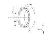
- FIG. 5 is a perspective view of the first support member 161 as viewed from the distal end side.
- FIG. 6 is a perspective view of the first support member 161 as viewed from the base end side.
- the first support member 161 is a ring-shaped member having a cavity 16 a therein, and is fitted on the outer periphery of the base member 11.
- the first support member 161 has an inner peripheral surface 16b and an outer peripheral surface 16c centered on the central axis C1.
- the central axis C1 of the first support member 161 coincides with the central axis C of the base member 11 (insertion section main body 4).
- the radius R1 of the inner peripheral surface 16b of the first support member 161 substantially matches the radius of the outer periphery of the base member 11, and the inner peripheral surface 16b of the first support member 161 is Contact
- the radius R2 of the outer peripheral surface 16c substantially coincides with the radius of the inner periphery of the rotary tubular member 12, and the outer peripheral surface 16c of the first support member 161 contacts the inner peripheral surface of the rotary tubular member 12.
- the first support member 161 has, on the distal end side, an opening communicating with the cavity 16 a formed around the circumference. As shown in FIG. 6, the base end side of the first support member 161 does not have an opening communicating with the cavity 16a. Therefore, the fluid that has flowed into the cavity 16a from the opening is not discharged outside from the opening.
- the second support member 162 is the same as the first support member 161 except that the orientation in which the second support member 162 is arranged is opposite in the Z-axis direction.
- the inner peripheral surface 16b of the second support member 162 contacts the proximal outer peripheral surface 112 of the base member 11.
- the seal member 17 (the first seal member 171 and the second seal member 172) is disposed in a gap between the outer peripheral surface 11c of the base member 11 and the inner peripheral surface 12b of the rotary tubular member 12, as shown in FIG. I have.
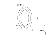
- FIG. 7 is a perspective view of the first seal member 171 as viewed from the proximal end side.
- FIG. 8 is a perspective view of the first seal member 171 as viewed from the distal end side.
- the first seal member 171 is a ring-shaped member having a cavity 17 a therein, and is fitted on the outer periphery of the base member 11. As shown in FIG. 2, the first seal member 171 is disposed on the front end side (end side) of the first support member 161.
- the first seal member 171 has an inner peripheral surface 17b and an outer peripheral surface 17c centered on the central axis C2.
- the central axis C2 of the first seal member 171 coincides with the central axis C of the base member 11 (insertion section main body 4).
- the first seal member 171 has an opening communicating with the cavity 17 a formed on the circumference at the base end side.
- the first seal member 171 is formed of a material having elasticity.
- the first seal member 171 is arranged such that the inner peripheral surface 17 b contacts the distal outer peripheral surface 111 of the base member 11 and the outer peripheral surface 17 c contacts the inner peripheral surface of the rotary tubular member 12.
- the first seal member 171 is arranged in a state where the inner peripheral surface 17b and the outer peripheral surface 17c are moved in a direction of approaching each other.
- the inner peripheral surface 17 b and the distal outer peripheral surface 111 are in contact with each other without a gap.
- the outer peripheral surface 17c and the inner peripheral surface of the rotary tubular member 12 are in contact with each other without any gap.
- the vicinity of each contact surface may be water-repellent.
- the first seal member 171 has a convex portion 17d formed around the circumference at the distal end side.
- the second seal member 172 is the same as the first seal member 171 except that the arrangement direction is opposite in the Z-axis direction.
- the second seal member 172 is arranged such that the inner peripheral surface 17 b is in contact with the proximal outer peripheral surface 112 of the base member 11.
- the pipe 18 is a pipe connecting the shielding portion 15 and the fluid pipe 27 as shown in FIGS. 2 and 4.
- the pipe 18 provides the air supplied from the fluid pipe 27 to the shielding unit 15.
- the shielding portion 15 forms a shielding space surrounded by the outer peripheral surface 11c of the base member 11, the inner peripheral surface 12b of the rotary tubular member 12, the support member 16, and the seal member 17. Therefore, most of the air supplied to the shielding unit 15 is stored in the shielding unit 15. By supplying a large amount of air to the shielding unit 15, the shielding unit 15 is in a high pressure state as compared with the outside of the shielding unit 15.
- a stopper or the like is provided so that the positions of the support member 16 and the seal member 17 in the Z-axis direction do not change even when the shielding section 15 is in a high-pressure state.
- the spacer 19 is a ring-shaped member provided between the distal-side shield 151 and the proximal-side shield 152 in a direction parallel to the longitudinal axis C.
- the spacer 19 is attached to the base member 11.
- the spacer 19 is provided coaxially with the longitudinal axis C, and supports the rotating tubular member 12 between the base member 11 and the rotating tubular member 12 in the radial direction.
- the spacer 19 holds the rotating tubular member 12 coaxially with the longitudinal axis C even when an external force acts on the rotating tubular member 12.
- the surgeon inserts the insertion section 2 in which the in-vivo insertion mechanism 6 is attached to the rotating tubular member 12 into the body. Air is supplied from the fluid pipe 27 to the shielding unit 15, and the shielding unit 15 is maintained in a high pressure state.
- the operator operates the switch 31 of the operation unit 3 to drive the motor and rotate the shaft 13 in the direction around the longitudinal axis.
- the drive member 14 is driven by rotation about the longitudinal axis of the shaft 13 and rotates the rotary tubular member 12 in a direction around the longitudinal axis.
- the gap between the shielding portion 15 and the outer peripheral surface 11c of the base member 11 is small. Further, a gap between the shielding portion 15 and the outer peripheral surface 11c of the base member 11 is small. Therefore, even when the rotating tubular member 12 rotates in the direction around the longitudinal axis with respect to the base member 11, the shielding portion 15 is maintained in a high pressure state. Even if air escapes from the shielding part 15 to the outside of the shielding part 15, the high pressure state of the shielding part 15 can be maintained by supplying additional air to the shielding part 15 from the fluid pipe 27. .
- the endoscope device 100 which is the insertion device according to the present embodiment, the rotation performance of the rotary tubular member 12 with respect to the base member 11 (insertion unit main body 4) is ensured, and the driving member arrangement space of the base member 11 is secured. It is possible to preferably prevent the liquid from flowing into 11s.
- the shielding portion 15 has the distal-side shielding portion 151 and the proximal-side shielding portion 152, but the mode of the shielding portion is not limited to this.
- the shielding portion may be a single space including the driving member arrangement space 11s without the support member 16. In this case, the driving member arrangement space 11s is also maintained at a high pressure. As in the above embodiment, it is possible to preferably prevent the liquid from flowing into the driving member arrangement space 11s.
- the shielding unit 15 maintains the high pressure state by the air supplied from the fluid pipe 27, but the mode of the shielding unit is not limited to this.
- Water may be supplied to the shielding unit from the fluid pipe, and the high pressure state may be maintained by the supplied water.
- the water supplied by the fluid pipe may be the same as the water supplied by the water supply channel 26, or may be a different water source.
- the shielding unit 15 stores most of the air supplied from the fluid pipe 27 and maintains the high pressure state, but the mode of the shielding unit is not limited to this.
- the shielding section may have a gap communicating with the external space of the insertion section 2, and may discharge air or water to the outside from the gap. By discharging a part of the air and water to the outside while maintaining the high pressure state by the supplied air and water, the inflow of the liquid into the driving member arrangement space 11s of the base member 11 is more suitably prevented. be able to. Even when dirt and the like adhere to the vicinity of the shielding portion, the dirt and the like can be eliminated by air and water discharged to the outside.
- the seal member 17 was not attached to either the base member 11 or the rotary tubular member 12, but the form of the seal member is not limited to this.
- the seal member may be attached to either the base member 11 or the rotary tubular member 12. Even in this case, the rotation performance of the rotary tubular member 12 with respect to the base member 11 is ensured, and the inflow of the liquid into the driving member arrangement space 11s of the base member 11 can be suitably prevented.
- at least one of the base member 11 and the rotating tubular member 12 that rotates with respect to the seal member may include a member such as an O-ring that reduces frictional resistance during rotation.
- the sealing member 17 blocks the shielding unit 15 from the external space of the insertion unit 2, but the mode of the shielding unit is not limited to this.
- the shield may have a labyrinth seal instead of the seal member 17. A part of the air and water can be discharged from the shield to the outside while the high pressure state of the shield is maintained by the supplied air and water.
- the endoscope device 100B which is the insertion device according to the present embodiment, includes an insertion portion 2B inserted into a lumen of a living body, and an operation portion 3 provided on a proximal end side of the insertion portion 2B.
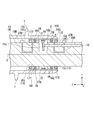
- FIG. 9 is a cross-sectional view in the longitudinal direction of the insertion section 2B of the endoscope device 100B.
- the insertion section 2B includes a long insertion section main body 4 extending along the longitudinal axis C of the insertion section 2B, a bending section 5 provided on the distal end side of the insertion section main body 4, a living body insertion mechanism 6, , A rotation mechanism 10B.
- the insertion portion 2B is centered on the longitudinal axis C, and is inserted into a body cavity when the endoscope device 100B is used.
- the insertion portion 2B is provided with a plurality of channels 20, which are passages (internal cavities) extending from the distal end portion 5a to the entire length of the insertion portion 2B.
- a curved wire 21, an imaging cable 22, a light guide 23, a treatment instrument channel 24, an air supply channel 25, and a water supply channel 26 extend along the longitudinal axis C. ing. No fluid piping is provided in the insertion portion 2B.
- the rotating mechanism 10B includes a base member 11, a rotating tubular member 12, a driving member 14, a shielding part 15, a pipe 18B, a spacer 19, and a pipe connecting part 27B. .
- Piping connection part (fluid supply part) 27B is a joint for supplying fluid (air or water) to pipe 18B, and the joint port is provided with a septum or a lid having a sealing function.
- the pipe 18B is a pipe connecting the shielding part 15 and the pipe connection part 27B. By inserting a fluid from the pipe connection part 27B, the shielding part 15 can be brought into a high pressure state.
- the surgeon Before inserting the insertion section 2 into the body, the surgeon inserts a fluid from the pipe connection section 27B to bring the shielding section 15 into a high pressure state.
- the operator inserts the insertion section 2 in which the in-vivo insertion mechanism 6 is attached to the rotating tubular member 12 into the body.
- the operator operates the switch 31 of the operation unit 3 to drive the motor and rotate the shaft 13 in the direction around the longitudinal axis.
- the drive member 14 is driven by rotation about the longitudinal axis of the shaft 13 and rotates the rotary tubular member 12 in a direction around the longitudinal axis.
- the rotation performance of the rotary tubular member 12 with respect to the base member 11 is ensured, and the driving member arrangement space of the base member 11 is provided. It is possible to preferably prevent the liquid from flowing into 11s.
- the shielding section 15 can be brought into a high pressure state without providing a fluid pipe in the insertion section 2B.
- the second embodiment of the present invention has been described in detail with reference to the drawings.
- the specific configuration is not limited to this embodiment, and includes a design change and the like without departing from the gist of the present invention.
- the components shown in the above-described embodiments and modified examples can be appropriately combined and configured.
- FIG. 10 is a cross-sectional view of a rotation mechanism 10C which is a modification of the rotation mechanism 10B.
- the rotation mechanism 10C has a fluid pipe (fluid supply part) 27C connected to the pipe connection part 27B.
- the fluid pipe 27C is connected to the pump at the base end, and provides the shielding section 15 with air supplied from the pump.
- the fluid pipe 27C can be inserted into the body, and is inserted into the body along with the insertion section 2 along the insertion section 2. Even if air escapes from the shielding unit 15 to the outside of the shielding unit 15, the high pressure state of the shielding unit 15 can be maintained by supplying additional air to the shielding unit 15 from the fluid pipe 27C. .
- the present invention can be applied to an insertion device such as an endoscope device having a rotation mechanism.
Landscapes
- Health & Medical Sciences (AREA)
- Life Sciences & Earth Sciences (AREA)
- Surgery (AREA)
- Biomedical Technology (AREA)
- Medical Informatics (AREA)
- Optics & Photonics (AREA)
- Pathology (AREA)
- Radiology & Medical Imaging (AREA)
- Biophysics (AREA)
- Engineering & Computer Science (AREA)
- Physics & Mathematics (AREA)
- Heart & Thoracic Surgery (AREA)
- Nuclear Medicine, Radiotherapy & Molecular Imaging (AREA)
- Molecular Biology (AREA)
- Animal Behavior & Ethology (AREA)
- General Health & Medical Sciences (AREA)
- Public Health (AREA)
- Veterinary Medicine (AREA)
- Instruments For Viewing The Inside Of Hollow Bodies (AREA)
- Endoscopes (AREA)
Abstract
挿入機構は、長手軸に沿って延設された挿入部本体と、前記挿入部本体の一部に一体に形成され、前記挿入部本体の外部空間に連通する駆動部材配置空間を規定するベース部材と、前記ベース部材の外周に配置された回転筒状部材と、前記駆動部材配置空間に配置され、前記回転筒状部材を前記長手軸を中心に回転させる駆動部材と、前記ベース部材と前記回転筒状部材との隙間に形成された遮蔽部と、前記遮蔽部に流体を輸送可能な配管と、を備え、前記遮蔽部は、前記ベース部材と前記回転筒状部材との隙間に形成された空間であり、前記配管から輸送される前記流体により高圧に保たれる。
Description
本発明は、回転機構を備えた挿入装置に関する。
管腔内の画像観察用の撮像部が先端に設けられた挿入部を有する内視鏡装置等の医療機器を管腔内へ挿入する処置をアシストする回転機構が知られている。
特許文献1には、長手軸回りに回転する医療用回転機構を挿入部に備えた内視鏡装置が記載されている。
また、特許文献2には、螺旋状フィンを回転させる回転筒状部材を挿入部に備えた挿入装置が記載されている。挿入装置は、回転筒状部材の挿入部に対する回転性能が確保され、かつ、外部から挿入部内部への液体の流入が有効に防止される。
しかしながら、特許文献2に記載の挿入装置において、回転筒状部材と挿入部との間に隙間が生じ、隙間から水や汚れなどの侵入を完全に防止することは難しかった。
上記事情を踏まえ、本発明は、回転筒状部材の挿入部に対する回転性能が確保され、かつ、挿入部への液体の流入が好適に防止される挿入装置を提供することを目的とする。
上記課題を解決するために、この発明は以下の手段を提案している。
本発明の第一の態様に係る挿入装置は、長手軸に沿って延設された挿入部本体と、前記挿入部本体の一部に一体に形成され、前記挿入部本体の外部空間に連通する駆動部材配置空間を規定するベース部材と、前記ベース部材の外周に配置された回転筒状部材と、前記駆動部材配置空間に配置され、前記回転筒状部材を前記長手軸を中心に回転させる駆動部材と、前記ベース部材と前記回転筒状部材との隙間に形成された遮蔽部と、前記遮蔽部に流体を輸送可能な配管と、を備え、前記遮蔽部は、前記ベース部材と前記回転筒状部材との隙間に形成された空間であり、前記配管から輸送される前記流体により高圧に保たれる。
本発明の第一の態様に係る挿入装置は、長手軸に沿って延設された挿入部本体と、前記挿入部本体の一部に一体に形成され、前記挿入部本体の外部空間に連通する駆動部材配置空間を規定するベース部材と、前記ベース部材の外周に配置された回転筒状部材と、前記駆動部材配置空間に配置され、前記回転筒状部材を前記長手軸を中心に回転させる駆動部材と、前記ベース部材と前記回転筒状部材との隙間に形成された遮蔽部と、前記遮蔽部に流体を輸送可能な配管と、を備え、前記遮蔽部は、前記ベース部材と前記回転筒状部材との隙間に形成された空間であり、前記配管から輸送される前記流体により高圧に保たれる。
本発明の第二の態様によれば、第一の態様に係る挿入装置において、前記遮蔽部は、前記ベース部材の外周に配置されるリング状の支持部材と、前記ベース部材の外周かつ前記支持部材より端部側に配置されるリング状のシール部材と、を有し、前記遮蔽部は、前記ベース部材の外周面と、前記回転筒状部材の内周面と、前記支持部材と、前記シール部材と、に囲まれた空間であってもよい。
本発明の第三の態様によれば、第二の態様に係る挿入装置において、前記シール部材は、弾性を有する素材で形成されており、前記ベース部材の外周面および前記回転筒状部材の内周面と隙間なく接触してもよい。
本発明の第四の態様によれば、第二の態様に係る挿入装置において、前記シール部材は、前記ベース部材の外周面および前記回転筒状部材の内周面の少なくとも一方に隙間を有しており、前記遮蔽部に輸送された流体の一部を前記隙間から外部に排出してもよい。
本発明の第五の態様によれば、第二から第四のいずれかの態様に係る挿入装置において、前記ベース部材の外周面と前記回転筒状部材の内周面の少なくとも一方は、前記シール部材の近傍が撥水加工されていてもよい。
本発明の挿入装置によれば、回転筒状部材の挿入部に対する回転性能が確保され、かつ、挿入部への液体の流入を好適に防止することができる。
(第一実施形態)
本発明の第一実施形態について、図1から図8を参照して説明する。
本発明の第一実施形態について、図1から図8を参照して説明する。
図1は、本実施形態に係る挿入装置である内視鏡装置100の概念的な外観構成を示す図である。内視鏡装置(挿入装置)100は、図1に示すように、生体の管腔内に挿入される挿入部2と、挿入部2の基端側に設けられた操作部3と、を備える。
挿入部2は、図1に示すように、挿入部2の長手軸Cに沿って延設される長尺の挿入部本体4と、挿入部本体4の先端側に設けられた湾曲部5と、生体内挿入機構6と、回転機構10と、を備えている。挿入部2は、長手軸Cを軸中心とし、内視鏡装置100の使用時には体腔内に挿入される。
湾曲部5は、管腔の曲がりに合わせて湾曲する長尺部材である。湾曲部5の先端部5aには、図示しない撮像部が設けられている。
生体内挿入機構6は、挿入部本体4または湾曲部5の外周上に間隙を空けて嵌合する筒状の部材であり、回転機構10に着脱可能に取り付けられる。生体内挿入機構6は、推進部位および後退部位として機能するフィン7と、長手軸を中心に回転して、導入推進として機能するスパイラルチューブ(導入推進部)9と、を有している。
フィン7は、スパイラルチューブ9の外周に螺旋状に巻き付けられている。フィン7が巻き付く螺旋方向と逆方向にスパイラルチューブ9を回転させることにより、生体内挿入機構6は管腔内で前進する。逆に、フィン7が巻き付く螺旋方向にスパイラルチューブ9を回転させることにより、生体内挿入機構6は管腔内で後退する。
スパイラルチューブ9は、湾曲部5の湾曲に従う柔軟性を有する材料(例えば、ゴム材料や樹脂材料)又は構造等を有している。スパイラルチューブ9の先端側は、先絞り形状に形成されており、管腔内に挿入しやすい。
生体内挿入機構6は、回転機構10に着脱可能に取り付けられる使い捨て品(ディスポーザブル品)であり、感染防止のために処置ごとに交換可能である。
回転機構10は、スパイラルチューブ9を挿入部2の長手軸を中心に回転させ、挿入部2の管腔内への導入をアシストする。回転機構10は、スパイラルチューブ9を両方向(CW,CCW)に回転可能である。
回転機構10は、挿入部2の内部を挿通するシャフト13の第一端が連結され、シャフト13の第二端は、操作部3に設けられた図示しないモータに連結されている。モータは、シャフト13を長手軸を中心として回転させ、回転機構10の一部を回転させる。
操作部3には、湾曲部5の湾曲操作や回転機構10の回転を含めた種々の操作を行うための操作ノブ30及びスイッチ31が配置されている。また、操作部3には、処置具を挿入する処置具挿入部32が設けられている。
図2は挿入部2の長手軸C方向における断面図である。図3は図2に示す挿入部2の長手軸Cに垂直なA-A断面の断面図である。図4は図2に示す挿入部2の長手軸Cに垂直なB-B断面の断面図である。以降の説明において、A-A断面およびB-B断面をXY平面、挿入部2の長手軸C方向をZ軸方向とも称す。
挿入部2には先端部5aから挿入部2の全長に及ぶ通路(内部空洞)であるチャンネル20が複数設けられている。図3および図4に示すように、挿入部2の内部には、湾曲ワイヤ21と、撮像ケーブル22と、ライトガイド23と、処置具チャンネル24と、送気チャンネル25と、送水チャンネル26と、流体用配管27と、が長手軸Cに沿って延設されている。
湾曲ワイヤ21は、4本設けられており、湾曲部5を4方向に湾曲させる。湾曲ワイヤ21の基端は、操作部3の操作ノブ30に接続されている。湾曲ワイヤ21の先端は、湾曲部5の先端部5aに接続されている。操作ノブ30を用いた湾曲操作により、湾曲ワイヤ21が牽引され、湾曲部5が湾曲する。
撮像ケーブル22は、湾曲部5の先端部5aに設けられた撮像部に接続されている。撮像ケーブル22は、挿入部2の内部および操作部3の内部を通って延設され、画像処理機能を有する周辺ユニットに接続されている。
ライトガイド23は、基端において光源に接続されている。光源から出射された光は、ライトガイド23によって導光され、湾曲部5の先端部5aから被写体に照射される。
処置具チャンネル24は、把持鉗子等の処置具が挿入されるチャンネルである。処置具チャンネル24は、挿入部2の内部および操作部3の内部を通って、基端が処置具挿入部32に接続されている。処置具挿入部32から挿入された処置具は、処置具チャンネル24の内部を通って、湾曲部5の先端部5aの開口から先端方向に向かって突出する。
送気チャンネル25は、基端においてポンプに接続されており、操作部3のスイッチ31の操作に基づき、ポンプから送気される空気を湾曲部5の先端部5aのノズルから排出する。排出される空気は、例えば、先端部5aに付着した付着物を取り除いたり、内視鏡検査時に空気を送気して腸管を膨らましたりする。
送水チャンネル26は、基端において送水タンクに接続されており、操作部3のスイッチ31の操作に基づき、送水タンクから送水される水を湾曲部5の先端部5aのノズルから排出する。排出される水は、例えば、先端部5aに付着した汚れを取り除いたり、被写体を洗浄したりする。
流体用配管(流体供給部)27は、基端において、ポンプに接続されており、ポンプから送気される空気を、後述する遮蔽部15に提供する。なお、流体用配管27が接続されるポンプは、送気チャンネル25が接続されるポンプと同じものであってもよいし、別のものであってもよい。
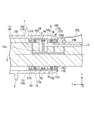
回転機構10は、図2に示すように、ベース部材11と、回転筒状部材12と、駆動部材14と、遮蔽部15と、配管18と、スペーサ19と、を有する。
ベース部材11は、挿入部本体4の一部に一体に形成されている。ベース部材11は、挿入部本体4の一部であるため、長手軸Cが軸中心となる。ベース部材11は、挿入部本体4の外部空間に連通する開口部11aを有する駆動部材配置空間11sを規定する。駆動部材配置空間11sには駆動部材14が配置される。
回転筒状部材12は、挿入部本体4の外周に配置された筒状部材である。回転筒状部材12は駆動部材配置空間11sを覆う位置に配置されている。回転筒状部材12は、挿入部本体4に対して長手軸回り方向に回転可能である。回転筒状部材12の外周部には、スパイラルチューブ9の基端部が密着状態で接触している。これにより、スパイラルチューブ9が回転筒状部材12に対して固定され、スパイラルチューブ9が回転筒状部材12と一体に長手軸回り方向に回転する。
駆動部材14は、駆動部材配置空間11sに配置され、シャフト13の第一端が連結されている。駆動部材14は、シャフト13の長手軸を中心とした回転により駆動され、回転筒状部材12を長手軸回り方向に回転させる。駆動部材14の外周には、外歯ギア14gが設けられている。
回転筒状部材12の内周部には、外歯ギア14gと噛合う内歯ギア12gが設けられている。内歯ギア12gは、長手軸回り方向において回転筒状部材12の内周に渡って設けられている。このため、外歯ギア14gが回転することにより、回転筒状部材12が長手軸回り方向に回転する。すなわち、回転筒状部材12と駆動部材14とは、一ヶ所で内接噛合する外歯歯車および内歯歯車として機能する。外歯ギア14gと内歯ギア12gとは、駆動部材配置空間11sの開口部11a付近で内接噛合している。
遮蔽部15は、ベース部材11の外周面11cと回転筒状部材12の内周面12bとの隙間に形成されたリング状の遮蔽空間であり、駆動部材配置空間11sへの外部からの流体等の侵入を遮蔽する。遮蔽部15は、支持部材16(第一支持部材161および第二支持部材162)と、シール部材17(第一シール部材171および第二シール部材172)と、を有する。
遮蔽部15は、ベース部材11の外周面11cと、回転筒状部材12の内周面12bと、支持部材16と、シール部材17と、に囲まれた遮蔽空間を形成する。遮蔽部15は、先端側遮蔽部151と基端側遮蔽部152とを有する。
先端側遮蔽部151は、ベース部材11の先端側外周面111と、回転筒状部材12の内周面12bと、第一支持部材161と、第一シール部材171と、に囲まれた遮蔽空間である。ここで、先端側外周面111は、ベース部材11の外周面11cにおいて、駆動部材配置空間11sの開口部11aより先端方向の外周面11cである。
基端側遮蔽部152は、ベース部材11の基端側外周面112と、回転筒状部材12の内周面12bと、第二支持部材162と、第二シール部材172と、に囲まれた遮蔽空間である。ここで、基端側外周面112は、ベース部材11の外周面11cにおいて、駆動部材配置空間11sの開口部11aより基端方向の外周面11cである。
支持部材16(第一支持部材161および第二支持部材162)は、図2に示すように、ベース部材11の外周面11cと回転筒状部材12の内周面12bとの隙間に配置されている。
図5は、第一支持部材161を先端側から見た斜視図である。図6は、第一支持部材161を基端側から見た斜視図である。
第一支持部材161は、内部に空洞16aを有するリング状部材であり、ベース部材11の外周上に嵌合する。第一支持部材161は、中心軸C1を中心とした内周面16bと外周面16cを有する。第一支持部材161の中心軸C1は、ベース部材11(挿入部本体4)の中心軸Cに一致している。
第一支持部材161は、内部に空洞16aを有するリング状部材であり、ベース部材11の外周上に嵌合する。第一支持部材161は、中心軸C1を中心とした内周面16bと外周面16cを有する。第一支持部材161の中心軸C1は、ベース部材11(挿入部本体4)の中心軸Cに一致している。
第一支持部材161の内周面16bの半径R1は、ベース部材11の外周の半径と略一致しており、第一支持部材161の内周面16bは、ベース部材11の先端側外周面111に接触する。外周面16cの半径R2は、回転筒状部材12の内周の半径と略一致しており、第一支持部材161の外周面16cは、回転筒状部材12の内周面に接触する。
第一支持部材161は、図5に示すように、先端側において、空洞16aに通じる開口が円周に渡って形成されている。図6に示すように、第一支持部材161の基端側は、空洞16aに通じる開口を有さない。そのため、開口から空洞16aに流入した流体は、開口以外から外部に排出されない。
第二支持部材162は、配置される向きがZ軸方向において反対である点を除いて、第一支持部材161と同じである。第二支持部材162の内周面16bは、ベース部材11の基端側外周面112に接触する。
シール部材17(第一シール部材171および第二シール部材172)は、図2に示すように、ベース部材11の外周面11cと回転筒状部材12の内周面12bとの隙間に配置されている。
図7は、第一シール部材171を基端側から見た斜視図である。図8は、第一シール部材171を先端側から見た斜視図である。
第一シール部材171は、内部に空洞17aを有するリング状部材であり、ベース部材11の外周上に嵌合する。第一シール部材171は、図2に示すように、第一支持部材161より先端側(端部側)に配置される。第一シール部材171は、中心軸C2を中心とした内周面17bと外周面17cを有する。第一シール部材171の中心軸C2は、ベース部材11(挿入部本体4)の中心軸Cに一致している。
第一シール部材171は、内部に空洞17aを有するリング状部材であり、ベース部材11の外周上に嵌合する。第一シール部材171は、図2に示すように、第一支持部材161より先端側(端部側)に配置される。第一シール部材171は、中心軸C2を中心とした内周面17bと外周面17cを有する。第一シール部材171の中心軸C2は、ベース部材11(挿入部本体4)の中心軸Cに一致している。
第一シール部材171は、図7に示すように、基端側において、空洞17aに通じる開口が円周に渡って形成されている。第一シール部材171は、弾性を有する素材で形成されており、空洞17aを挟んで両側に配置される内周面17bと外周面17cとが近づく方向に移動すると、元の位置に戻る復元力が発生する。第一シール部材171は、内周面17bをベース部材11の先端側外周面111に接触させ、外周面17cを回転筒状部材12の内周面に接触させて配置されている。また、第一シール部材171は、内周面17bと外周面17cとが近づく方向に移動させた状態で配置されている。そのため、第一シール部材171の復元力により、内周面17bと先端側外周面111とは隙間なく接触している。また、外周面17cと回転筒状部材12の内周面とは隙間なく接触している。なお、それぞれの接触面付近が撥水加工されていてもよい。
第一シール部材171は、図8に示すように、先端側において、凸部17dが円周に渡って形成されている。
第二シール部材172は、配置される向きが、Z軸方向において反対である点を除いて、第一シール部材171と同じである。第二シール部材172は、内周面17bをベース部材11の基端側外周面112に接触させて配置されている。
配管18は、図2および図4に示すように、遮蔽部15と流体用配管27とを接続する管路である。配管18は、流体用配管27から供給される空気を遮蔽部15に提供する。遮蔽部15は、ベース部材11の外周面11cと、回転筒状部材12の内周面12bと、支持部材16と、シール部材17と、に囲まれた遮蔽空間を形成している。そのため、遮蔽部15の供給された空気のほとんどは、遮蔽部15に収容される。多くの空気を遮蔽部15に供給することで、遮蔽部15は遮蔽部15外部と比較して高圧状態となる。
なお、遮蔽部15が高圧状態となった場合であっても、支持部材16およびシール部材17のZ軸方向の位置が変化しないように、ストッパ等が設けられている。
スペーサ19は、長手軸Cに平行な方向において、先端側遮蔽部151と基端側遮蔽部152との間に設けたリング状部材である。スペーサ19はベース部材11に取り付けられている。スペーサ19は、長手軸Cと同軸に設けられ、径方向においてベース部材11と回転筒状部材12との間で回転筒状部材12を支持している。スペーサ19は、回転筒状部材12に外力が作用した場合であっても、回転筒状部材12を長手軸Cと同軸に保持する。
次に、内視鏡装置100の動作について説明する。
術者は、回転筒状部材12に生体内挿入機構6が取り付けられた挿入部2を体内に挿入する。流体用配管27から空気が遮蔽部15に供給され、遮蔽部15は高圧状態に維持される。術者は、操作部3のスイッチ31を操作して、モータを駆動し、シャフト13を長手軸回り方向に回転させる。駆動部材14は、シャフト13の長手軸を中心とした回転により駆動され、回転筒状部材12を長手軸回り方向に回転させる。
術者は、回転筒状部材12に生体内挿入機構6が取り付けられた挿入部2を体内に挿入する。流体用配管27から空気が遮蔽部15に供給され、遮蔽部15は高圧状態に維持される。術者は、操作部3のスイッチ31を操作して、モータを駆動し、シャフト13を長手軸回り方向に回転させる。駆動部材14は、シャフト13の長手軸を中心とした回転により駆動され、回転筒状部材12を長手軸回り方向に回転させる。
回転筒状部材12がベース部材11に対して長手軸回り方向に回転した場合においても、遮蔽部15とベース部材11の外周面11cとの隙間はわずかである。また、遮蔽部15とベース部材11の外周面11cとの隙間はわずかである。そのため、回転筒状部材12がベース部材11に対して長手軸回り方向に回転した場合においても、遮蔽部15は高圧状態に維持される。遮蔽部15から空気が遮蔽部15の外部に抜けた場合であっても、追加の空気を流体用配管27から遮蔽部15に供給することで、遮蔽部15の高圧状態を維持することができる。
遮蔽部15は高圧状態に維持されているため、挿入部2の外部から遮蔽部15に水や汚れが侵入できない。そのため、挿入部2の外部から駆動部材配置空間11sへの浸水等を好適に防ぐことができる。
一方、遮蔽部15は、支持部材16とシール部材17のみが、回転筒状部材12とベース部材11に接触しているため、回転筒状部材12のベース部材11に対する回転性能が好適に確保される。
本実施形態に係る挿入装置である内視鏡装置100によれば、回転筒状部材12のベース部材11(挿入部本体4)に対する回転性能が確保され、かつ、ベース部材11の駆動部材配置空間11sへの液体の流入を好適に防止することができる。
以上、本発明の第一実施形態について図面を参照して詳述したが、具体的な構成はこの実施形態に限られるものではなく、本発明の要旨を逸脱しない範囲の設計変更等も含まれる。また、上述の実施形態および以下で示す変形例において示した構成要素は適宜に組み合わせて構成することが可能である。
(変形例1)
上記の実施形態では、遮蔽部15は先端側遮蔽部151と基端側遮蔽部152とを有したが、遮蔽部の態様はこれに限定されない。遮蔽部は、支持部材16を有さず、駆動部材配置空間11sを含む一つの空間であってもよい。この場合、駆動部材配置空間11sも高圧に維持される。上記の実施形態同様、駆動部材配置空間11sへの液体の流入を好適に防止することができる。
上記の実施形態では、遮蔽部15は先端側遮蔽部151と基端側遮蔽部152とを有したが、遮蔽部の態様はこれに限定されない。遮蔽部は、支持部材16を有さず、駆動部材配置空間11sを含む一つの空間であってもよい。この場合、駆動部材配置空間11sも高圧に維持される。上記の実施形態同様、駆動部材配置空間11sへの液体の流入を好適に防止することができる。
(変形例2)
上記の実施形態では、遮蔽部15は流体用配管27から供給される空気により高圧状態を維持していたが、遮蔽部の態様はこれに限定されない。遮蔽部は、流体用配管から水が供給され、供給された水により高圧状態を維持してもよい。なお、流体用配管が供給する水は、送水チャンネル26が供給する水と水源が同じものであってもよいし、水源が別のものであってもよい。
上記の実施形態では、遮蔽部15は流体用配管27から供給される空気により高圧状態を維持していたが、遮蔽部の態様はこれに限定されない。遮蔽部は、流体用配管から水が供給され、供給された水により高圧状態を維持してもよい。なお、流体用配管が供給する水は、送水チャンネル26が供給する水と水源が同じものであってもよいし、水源が別のものであってもよい。
(変形例3)
上記の実施形態では、遮蔽部15は流体用配管27から供給される空気のほとんどを収容して高圧状態を維持していたが、遮蔽部の態様はこれに限定されない。遮蔽部は、挿入部2の外部空間に通じる隙間を有してもよく、隙間から空気や水を外部に排出してもよい。供給された空気や水により高圧状態を維持しつつ、一部の空気や水を外部に排出することで、より好適にベース部材11の駆動部材配置空間11sへの液体の流入を好適に防止することができる。遮蔽部付近に汚れ等が付着した場合であっても、外部に排出される空気や水により、汚れ等を排除することができる。
上記の実施形態では、遮蔽部15は流体用配管27から供給される空気のほとんどを収容して高圧状態を維持していたが、遮蔽部の態様はこれに限定されない。遮蔽部は、挿入部2の外部空間に通じる隙間を有してもよく、隙間から空気や水を外部に排出してもよい。供給された空気や水により高圧状態を維持しつつ、一部の空気や水を外部に排出することで、より好適にベース部材11の駆動部材配置空間11sへの液体の流入を好適に防止することができる。遮蔽部付近に汚れ等が付着した場合であっても、外部に排出される空気や水により、汚れ等を排除することができる。
(変形例4)
上記の実施形態では、シール部材17は、ベース部材11と回転筒状部材12とのいずれにも取り付けられていなかったが、シール部材の態様はこれに限定されない。シール部材はベース部材11および回転筒状部材12のいずれかに取り付けられていてもよい。この場合であっても、回転筒状部材12のベース部材11に対する回転性能が確保され、かつ、ベース部材11の駆動部材配置空間11sへの液体の流入を好適に防止することができる。また、シール部材に対して回転するベース部材11と回転筒状部材12の少なくとも一方は、Oリング等の回転時の摩擦抵抗を削減する部材を有してもよい。
上記の実施形態では、シール部材17は、ベース部材11と回転筒状部材12とのいずれにも取り付けられていなかったが、シール部材の態様はこれに限定されない。シール部材はベース部材11および回転筒状部材12のいずれかに取り付けられていてもよい。この場合であっても、回転筒状部材12のベース部材11に対する回転性能が確保され、かつ、ベース部材11の駆動部材配置空間11sへの液体の流入を好適に防止することができる。また、シール部材に対して回転するベース部材11と回転筒状部材12の少なくとも一方は、Oリング等の回転時の摩擦抵抗を削減する部材を有してもよい。
(変形例5)
上記の実施形態では、遮蔽部15は、シール部材17が遮蔽部15と挿入部2の外部空間との遮断を行っていたが、遮蔽部の態様はこれに限定されない。遮蔽部は、シール部材17の代わりにラビリンスシールを有してもよい。供給された空気や水により遮蔽部の高圧状態を維持しつつ、一部の空気や水を遮蔽部から外部に排出することができる。
上記の実施形態では、遮蔽部15は、シール部材17が遮蔽部15と挿入部2の外部空間との遮断を行っていたが、遮蔽部の態様はこれに限定されない。遮蔽部は、シール部材17の代わりにラビリンスシールを有してもよい。供給された空気や水により遮蔽部の高圧状態を維持しつつ、一部の空気や水を遮蔽部から外部に排出することができる。
(第二実施形態)
本発明の第二実施形態について、図9を参照して説明する。以降の説明において、既に説明したものと共通する構成については、同一の符号を付して重複する説明を省略する。本実施形態は、挿入部が流体用配管を有さない点が第一実施形態と異なっている。
本発明の第二実施形態について、図9を参照して説明する。以降の説明において、既に説明したものと共通する構成については、同一の符号を付して重複する説明を省略する。本実施形態は、挿入部が流体用配管を有さない点が第一実施形態と異なっている。
本実施形態に係る挿入装置である内視鏡装置100Bは、生体の管腔内に挿入される挿入部2Bと、挿入部2Bの基端側に設けられた操作部3と、を備える。
図9は、内視鏡装置100Bの挿入部2Bの長手方向における断面図である。
挿入部2Bは、挿入部2Bの長手軸Cに沿って延設される長尺の挿入部本体4と、挿入部本体4の先端側に設けられた湾曲部5と、生体内挿入機構6と、回転機構10Bと、を備えている。挿入部2Bは、長手軸Cを軸中心とし、内視鏡装置100Bの使用時には体腔内に挿入される。
挿入部2Bは、挿入部2Bの長手軸Cに沿って延設される長尺の挿入部本体4と、挿入部本体4の先端側に設けられた湾曲部5と、生体内挿入機構6と、回転機構10Bと、を備えている。挿入部2Bは、長手軸Cを軸中心とし、内視鏡装置100Bの使用時には体腔内に挿入される。
挿入部2Bには先端部5aから挿入部2Bの全長に及ぶ通路(内部空洞)であるチャンネル20が複数設けられている。挿入部2Bの内部には、湾曲ワイヤ21と、撮像ケーブル22と、ライトガイド23と、処置具チャンネル24と、送気チャンネル25と、送水チャンネル26と、が長手軸Cに沿って延設されている。挿入部2Bには、流体用配管は設けられていない。
回転機構10Bは、図9に示すように、ベース部材11と、回転筒状部材12と、駆動部材14と、遮蔽部15と、配管18Bと、スペーサ19と、配管接続部27Bと、を有する。
配管接続部(流体供給部)27Bは、配管18Bに流体(空気や水)を供給する継手であり、継手口は、セプタムやシール機能を有するフタを備えている。配管18Bは、遮蔽部15と配管接続部27Bとを接続する管路である。配管接続部27Bから流体を挿入することで、遮蔽部15を高圧状態にすることができる。
術者は、挿入部2を体内に挿入する前に、配管接続部27Bから流体を挿入して遮蔽部15を高圧状態にする。次に、術者は、回転筒状部材12に生体内挿入機構6が取り付けられた挿入部2を体内に挿入する。術者は、操作部3のスイッチ31を操作して、モータを駆動し、シャフト13を長手軸回り方向に回転させる。駆動部材14は、シャフト13の長手軸を中心とした回転により駆動され、回転筒状部材12を長手軸回り方向に回転させる。
本実施形態に係る挿入装置である内視鏡装置100Bによれば、回転筒状部材12のベース部材11(挿入部本体4)に対する回転性能が確保され、かつ、ベース部材11の駆動部材配置空間11sへの液体の流入を好適に防止することができる。挿入部2Bに、流体用配管を設けなくても、遮蔽部15を高圧状態にすることができる。
以上、本発明の第二実施形態について図面を参照して詳述したが、具体的な構成はこの実施形態に限られるものではなく、本発明の要旨を逸脱しない範囲の設計変更等も含まれる。また、上述の実施形態および変形例において示した構成要素は適宜に組み合わせて構成することが可能である。
(変形例6)
上記の実施形態では、挿入部2を体内に挿入後、追加の空気を遮蔽部15に供給することができなかったが、遮蔽部の使用態様はこれに限定されない。図10は、回転機構10Bの変形例である回転機構10Cの断面図である。回転機構10Cは、配管接続部27Bと接続する流体用配管(流体供給部)27Cを有している。流体用配管27Cは、基端において、ポンプに接続されており、ポンプから送気される空気を、遮蔽部15に提供する。流体用配管27Cは、体内に挿入可能であり、挿入部2に沿って、挿入部2とともに体内に挿入される。遮蔽部15から空気が遮蔽部15の外部に抜けた場合であっても、追加の空気を流体用配管27Cから遮蔽部15に供給することで、遮蔽部15の高圧状態を維持することができる。
上記の実施形態では、挿入部2を体内に挿入後、追加の空気を遮蔽部15に供給することができなかったが、遮蔽部の使用態様はこれに限定されない。図10は、回転機構10Bの変形例である回転機構10Cの断面図である。回転機構10Cは、配管接続部27Bと接続する流体用配管(流体供給部)27Cを有している。流体用配管27Cは、基端において、ポンプに接続されており、ポンプから送気される空気を、遮蔽部15に提供する。流体用配管27Cは、体内に挿入可能であり、挿入部2に沿って、挿入部2とともに体内に挿入される。遮蔽部15から空気が遮蔽部15の外部に抜けた場合であっても、追加の空気を流体用配管27Cから遮蔽部15に供給することで、遮蔽部15の高圧状態を維持することができる。
本発明は、回転機構を有する内視鏡装置等の挿入装置に適用することができる。
100,100B 内視鏡装置(挿入装置)
2,2B 挿入部
3 操作部
30 操作ノブ
31 スイッチ
32 処置具挿入部
4 挿入部本体
5 湾曲部
5a 先端部
6 生体内挿入機構
7 フィン
9 スパイラルチューブ(導入推進部)
10,10B,10C 回転機構
11 ベース部材
111 先端側外周面
112 基端側外周面
11a 開口部
11c 外周面
11s 駆動部材配置空間
12 回転筒状部材
12b 内周面
12g 内歯ギア
13 シャフト
14 駆動部材
14g 外歯ギア
15 遮蔽部
151 先端側遮蔽部
152 基端側遮蔽部
16 支持部材
161 第一支持部材
162 第二支持部材
16a 空洞
16b 内周面
16c 外周面
17 シール部材
171 第一シール部材
172 第二シール部材
17a 空洞
17b 内周面
17c 外周面
18,18B 配管
19 スペーサ
20 チャンネル
21 湾曲ワイヤ
22 撮像ケーブル
23 ライトガイド
24 処置具チャンネル
25 送気チャンネル
26 送水チャンネル
27 流体用配管(流体供給部)
27B 配管接続部(流体供給部)
27C 流体用配管(流体供給部)
2,2B 挿入部
3 操作部
30 操作ノブ
31 スイッチ
32 処置具挿入部
4 挿入部本体
5 湾曲部
5a 先端部
6 生体内挿入機構
7 フィン
9 スパイラルチューブ(導入推進部)
10,10B,10C 回転機構
11 ベース部材
111 先端側外周面
112 基端側外周面
11a 開口部
11c 外周面
11s 駆動部材配置空間
12 回転筒状部材
12b 内周面
12g 内歯ギア
13 シャフト
14 駆動部材
14g 外歯ギア
15 遮蔽部
151 先端側遮蔽部
152 基端側遮蔽部
16 支持部材
161 第一支持部材
162 第二支持部材
16a 空洞
16b 内周面
16c 外周面
17 シール部材
171 第一シール部材
172 第二シール部材
17a 空洞
17b 内周面
17c 外周面
18,18B 配管
19 スペーサ
20 チャンネル
21 湾曲ワイヤ
22 撮像ケーブル
23 ライトガイド
24 処置具チャンネル
25 送気チャンネル
26 送水チャンネル
27 流体用配管(流体供給部)
27B 配管接続部(流体供給部)
27C 流体用配管(流体供給部)
Claims (5)
- 長手軸に沿って延設された挿入部本体と、
前記挿入部本体の一部に一体に形成され、前記挿入部本体の外部空間に連通する駆動部材配置空間を規定するベース部材と、
前記ベース部材の外周に配置された回転筒状部材と、
前記駆動部材配置空間に配置され、前記回転筒状部材を前記長手軸を中心に回転させる駆動部材と、
前記ベース部材と前記回転筒状部材との隙間に形成された遮蔽部と、
前記遮蔽部に流体を輸送可能な配管と、
を備え、
前記遮蔽部は、前記ベース部材と前記回転筒状部材との隙間に形成された空間であり、前記配管から輸送される前記流体により高圧に保たれる、
挿入装置。 - 前記遮蔽部は、前記ベース部材の外周に配置されるリング状の支持部材と、前記ベース部材の外周かつ前記支持部材より端部側に配置されるリング状のシール部材と、を有し、
前記遮蔽部は、前記ベース部材の外周面と、前記回転筒状部材の内周面と、前記支持部材と、前記シール部材と、に囲まれた空間である、
請求項1に記載の挿入装置。 - 前記シール部材は、弾性を有する素材で形成されており、前記ベース部材の外周面および前記回転筒状部材の内周面と隙間なく接触している、
請求項2に記載の挿入装置。 - 前記シール部材は、前記ベース部材の外周面および前記回転筒状部材の内周面の少なくとも一方に隙間を有しており、前記遮蔽部に輸送された流体の一部を前記隙間から外部に排出する、
請求項2に記載の挿入装置。 - 前記ベース部材の外周面と前記回転筒状部材の内周面の少なくとも一方は、前記シール部材の近傍が撥水加工されている、
請求項2から請求項4のいずれか一項に記載の挿入装置。
Priority Applications (1)
| Application Number | Priority Date | Filing Date | Title |
|---|---|---|---|
| PCT/JP2018/027093 WO2020016992A1 (ja) | 2018-07-19 | 2018-07-19 | 挿入装置 |
Applications Claiming Priority (1)
| Application Number | Priority Date | Filing Date | Title |
|---|---|---|---|
| PCT/JP2018/027093 WO2020016992A1 (ja) | 2018-07-19 | 2018-07-19 | 挿入装置 |
Publications (1)
| Publication Number | Publication Date |
|---|---|
| WO2020016992A1 true WO2020016992A1 (ja) | 2020-01-23 |
Family
ID=69163659
Family Applications (1)
| Application Number | Title | Priority Date | Filing Date |
|---|---|---|---|
| PCT/JP2018/027093 Ceased WO2020016992A1 (ja) | 2018-07-19 | 2018-07-19 | 挿入装置 |
Country Status (1)
| Country | Link |
|---|---|
| WO (1) | WO2020016992A1 (ja) |
Citations (3)
| Publication number | Priority date | Publication date | Assignee | Title |
|---|---|---|---|---|
| WO2012137364A1 (ja) * | 2011-04-08 | 2012-10-11 | オリンパスメディカルシステムズ株式会社 | 内視鏡 |
| JP2014524807A (ja) * | 2011-07-27 | 2014-09-25 | オリンパス エンド テクノロジー アメリカ インコーポレイテッド | 回転前進式カテーテル挿入システム |
| JP2017148227A (ja) * | 2016-02-24 | 2017-08-31 | オリンパス株式会社 | 挿入機器及び挿入装置 |
-
2018
- 2018-07-19 WO PCT/JP2018/027093 patent/WO2020016992A1/ja not_active Ceased
Patent Citations (3)
| Publication number | Priority date | Publication date | Assignee | Title |
|---|---|---|---|---|
| WO2012137364A1 (ja) * | 2011-04-08 | 2012-10-11 | オリンパスメディカルシステムズ株式会社 | 内視鏡 |
| JP2014524807A (ja) * | 2011-07-27 | 2014-09-25 | オリンパス エンド テクノロジー アメリカ インコーポレイテッド | 回転前進式カテーテル挿入システム |
| JP2017148227A (ja) * | 2016-02-24 | 2017-08-31 | オリンパス株式会社 | 挿入機器及び挿入装置 |
Similar Documents
| Publication | Publication Date | Title |
|---|---|---|
| US5458132A (en) | Endoscope cover-sheathed endoscope system | |
| US8821384B2 (en) | Attachment unit, endoscopic insertion section and endoscope | |
| CN107567301B (zh) | 具有电外科手术用工具的可操纵微型内窥镜和拉链式导管 | |
| CN102137615B (zh) | 用于内窥镜的器械 | |
| CN108289595A (zh) | 具有可角度调节的出射口的内窥镜附件 | |
| WO2008018256A1 (en) | Endoscope end device and container containing it | |
| CN104394752A (zh) | 插拔辅助器械 | |
| CN106455934A (zh) | 外套管和机械手系统 | |
| US11653817B2 (en) | Endoscope | |
| US20130331645A1 (en) | Endoscopic device and endoscope treatment system | |
| US20190008369A1 (en) | Endoscope | |
| JP5467183B1 (ja) | 挿入装置及び回転筒状部材 | |
| JP6496011B2 (ja) | 内視鏡の組立方法及び内視鏡 | |
| US9829080B2 (en) | Driving force transmission mechanism | |
| CN112004452B (zh) | 螺旋管和内窥镜 | |
| EP3656277B1 (en) | Endoscope | |
| WO2020016992A1 (ja) | 挿入装置 | |
| JPH06225851A (ja) | 内視鏡カバー方式の内視鏡 | |
| EP3656281B1 (en) | Endoscope | |
| EP2184003A1 (en) | Endoscope and flexible tube therefor | |
| JP3438917B2 (ja) | 内視鏡 | |
| JP4153731B2 (ja) | 電子走査式超音波内視鏡 | |
| JPS6289014A (ja) | 内視鏡 | |
| CN116367763A (zh) | 医疗设备 | |
| WO2020080236A1 (ja) | 内視鏡、及び処置具チャンネルユニット |
Legal Events
| Date | Code | Title | Description |
|---|---|---|---|
| 121 | Ep: the epo has been informed by wipo that ep was designated in this application |
Ref document number: 18926580 Country of ref document: EP Kind code of ref document: A1 |
|
| NENP | Non-entry into the national phase |
Ref country code: DE |
|
| 122 | Ep: pct application non-entry in european phase |
Ref document number: 18926580 Country of ref document: EP Kind code of ref document: A1 |
|
| NENP | Non-entry into the national phase |
Ref country code: JP |