WO2020013099A1 - 軸受システム、軸受システムの制御方法、及び軸受システムを制御するためのコンピュータプログラム - Google Patents
軸受システム、軸受システムの制御方法、及び軸受システムを制御するためのコンピュータプログラム Download PDFInfo
- Publication number
- WO2020013099A1 WO2020013099A1 PCT/JP2019/026903 JP2019026903W WO2020013099A1 WO 2020013099 A1 WO2020013099 A1 WO 2020013099A1 JP 2019026903 W JP2019026903 W JP 2019026903W WO 2020013099 A1 WO2020013099 A1 WO 2020013099A1
- Authority
- WO
- WIPO (PCT)
- Prior art keywords
- bearing
- execution unit
- unit
- condition
- measurement execution
- Prior art date
- Legal status (The legal status is an assumption and is not a legal conclusion. Google has not performed a legal analysis and makes no representation as to the accuracy of the status listed.)
- Ceased
Links
Images




Classifications
-
- F—MECHANICAL ENGINEERING; LIGHTING; HEATING; WEAPONS; BLASTING
- F16—ENGINEERING ELEMENTS AND UNITS; GENERAL MEASURES FOR PRODUCING AND MAINTAINING EFFECTIVE FUNCTIONING OF MACHINES OR INSTALLATIONS; THERMAL INSULATION IN GENERAL
- F16C—SHAFTS; FLEXIBLE SHAFTS; ELEMENTS OR CRANKSHAFT MECHANISMS; ROTARY BODIES OTHER THAN GEARING ELEMENTS; BEARINGS
- F16C41/00—Other accessories, e.g. devices integrated in the bearing not relating to the bearing function as such
-
- F—MECHANICAL ENGINEERING; LIGHTING; HEATING; WEAPONS; BLASTING
- F16—ENGINEERING ELEMENTS AND UNITS; GENERAL MEASURES FOR PRODUCING AND MAINTAINING EFFECTIVE FUNCTIONING OF MACHINES OR INSTALLATIONS; THERMAL INSULATION IN GENERAL
- F16C—SHAFTS; FLEXIBLE SHAFTS; ELEMENTS OR CRANKSHAFT MECHANISMS; ROTARY BODIES OTHER THAN GEARING ELEMENTS; BEARINGS
- F16C17/00—Sliding-contact bearings for exclusively rotary movement
- F16C17/04—Sliding-contact bearings for exclusively rotary movement for axial load only
- F16C17/06—Sliding-contact bearings for exclusively rotary movement for axial load only with tiltably-supported segments, e.g. Michell bearings
- F16C17/065—Sliding-contact bearings for exclusively rotary movement for axial load only with tiltably-supported segments, e.g. Michell bearings the segments being integrally formed with, or rigidly fixed to, a support-element
-
- F—MECHANICAL ENGINEERING; LIGHTING; HEATING; WEAPONS; BLASTING
- F16—ENGINEERING ELEMENTS AND UNITS; GENERAL MEASURES FOR PRODUCING AND MAINTAINING EFFECTIVE FUNCTIONING OF MACHINES OR INSTALLATIONS; THERMAL INSULATION IN GENERAL
- F16C—SHAFTS; FLEXIBLE SHAFTS; ELEMENTS OR CRANKSHAFT MECHANISMS; ROTARY BODIES OTHER THAN GEARING ELEMENTS; BEARINGS
- F16C17/00—Sliding-contact bearings for exclusively rotary movement
- F16C17/12—Sliding-contact bearings for exclusively rotary movement characterised by features not related to the direction of the load
- F16C17/24—Sliding-contact bearings for exclusively rotary movement characterised by features not related to the direction of the load with devices affected by abnormal or undesired positions, e.g. for preventing overheating, for safety
-
- F—MECHANICAL ENGINEERING; LIGHTING; HEATING; WEAPONS; BLASTING
- F16—ENGINEERING ELEMENTS AND UNITS; GENERAL MEASURES FOR PRODUCING AND MAINTAINING EFFECTIVE FUNCTIONING OF MACHINES OR INSTALLATIONS; THERMAL INSULATION IN GENERAL
- F16C—SHAFTS; FLEXIBLE SHAFTS; ELEMENTS OR CRANKSHAFT MECHANISMS; ROTARY BODIES OTHER THAN GEARING ELEMENTS; BEARINGS
- F16C17/00—Sliding-contact bearings for exclusively rotary movement
- F16C17/12—Sliding-contact bearings for exclusively rotary movement characterised by features not related to the direction of the load
- F16C17/24—Sliding-contact bearings for exclusively rotary movement characterised by features not related to the direction of the load with devices affected by abnormal or undesired positions, e.g. for preventing overheating, for safety
- F16C17/243—Sliding-contact bearings for exclusively rotary movement characterised by features not related to the direction of the load with devices affected by abnormal or undesired positions, e.g. for preventing overheating, for safety related to temperature and heat, e.g. for preventing overheating
-
- F—MECHANICAL ENGINEERING; LIGHTING; HEATING; WEAPONS; BLASTING
- F16—ENGINEERING ELEMENTS AND UNITS; GENERAL MEASURES FOR PRODUCING AND MAINTAINING EFFECTIVE FUNCTIONING OF MACHINES OR INSTALLATIONS; THERMAL INSULATION IN GENERAL
- F16C—SHAFTS; FLEXIBLE SHAFTS; ELEMENTS OR CRANKSHAFT MECHANISMS; ROTARY BODIES OTHER THAN GEARING ELEMENTS; BEARINGS
- F16C17/00—Sliding-contact bearings for exclusively rotary movement
- F16C17/12—Sliding-contact bearings for exclusively rotary movement characterised by features not related to the direction of the load
- F16C17/24—Sliding-contact bearings for exclusively rotary movement characterised by features not related to the direction of the load with devices affected by abnormal or undesired positions, e.g. for preventing overheating, for safety
- F16C17/246—Sliding-contact bearings for exclusively rotary movement characterised by features not related to the direction of the load with devices affected by abnormal or undesired positions, e.g. for preventing overheating, for safety related to wear, e.g. sensors for measuring wear
-
- F—MECHANICAL ENGINEERING; LIGHTING; HEATING; WEAPONS; BLASTING
- F16—ENGINEERING ELEMENTS AND UNITS; GENERAL MEASURES FOR PRODUCING AND MAINTAINING EFFECTIVE FUNCTIONING OF MACHINES OR INSTALLATIONS; THERMAL INSULATION IN GENERAL
- F16C—SHAFTS; FLEXIBLE SHAFTS; ELEMENTS OR CRANKSHAFT MECHANISMS; ROTARY BODIES OTHER THAN GEARING ELEMENTS; BEARINGS
- F16C33/00—Parts of bearings; Special methods for making bearings or parts thereof
- F16C33/30—Parts of ball or roller bearings
- F16C33/66—Special parts or details in view of lubrication
- F16C33/6637—Special parts or details in view of lubrication with liquid lubricant
- F16C33/6659—Details of supply of the liquid to the bearing, e.g. passages or nozzles
- F16C33/667—Details of supply of the liquid to the bearing, e.g. passages or nozzles related to conditioning, e.g. cooling, filtering
-
- F—MECHANICAL ENGINEERING; LIGHTING; HEATING; WEAPONS; BLASTING
- F16—ENGINEERING ELEMENTS AND UNITS; GENERAL MEASURES FOR PRODUCING AND MAINTAINING EFFECTIVE FUNCTIONING OF MACHINES OR INSTALLATIONS; THERMAL INSULATION IN GENERAL
- F16C—SHAFTS; FLEXIBLE SHAFTS; ELEMENTS OR CRANKSHAFT MECHANISMS; ROTARY BODIES OTHER THAN GEARING ELEMENTS; BEARINGS
- F16C37/00—Cooling of bearings
-
- F—MECHANICAL ENGINEERING; LIGHTING; HEATING; WEAPONS; BLASTING
- F16—ENGINEERING ELEMENTS AND UNITS; GENERAL MEASURES FOR PRODUCING AND MAINTAINING EFFECTIVE FUNCTIONING OF MACHINES OR INSTALLATIONS; THERMAL INSULATION IN GENERAL
- F16C—SHAFTS; FLEXIBLE SHAFTS; ELEMENTS OR CRANKSHAFT MECHANISMS; ROTARY BODIES OTHER THAN GEARING ELEMENTS; BEARINGS
- F16C37/00—Cooling of bearings
- F16C37/002—Cooling of bearings of fluid bearings
-
- F—MECHANICAL ENGINEERING; LIGHTING; HEATING; WEAPONS; BLASTING
- F16—ENGINEERING ELEMENTS AND UNITS; GENERAL MEASURES FOR PRODUCING AND MAINTAINING EFFECTIVE FUNCTIONING OF MACHINES OR INSTALLATIONS; THERMAL INSULATION IN GENERAL
- F16C—SHAFTS; FLEXIBLE SHAFTS; ELEMENTS OR CRANKSHAFT MECHANISMS; ROTARY BODIES OTHER THAN GEARING ELEMENTS; BEARINGS
- F16C41/00—Other accessories, e.g. devices integrated in the bearing not relating to the bearing function as such
- F16C41/007—Encoders, e.g. parts with a plurality of alternating magnetic poles
-
- F—MECHANICAL ENGINEERING; LIGHTING; HEATING; WEAPONS; BLASTING
- F16—ENGINEERING ELEMENTS AND UNITS; GENERAL MEASURES FOR PRODUCING AND MAINTAINING EFFECTIVE FUNCTIONING OF MACHINES OR INSTALLATIONS; THERMAL INSULATION IN GENERAL
- F16N—LUBRICATING
- F16N29/00—Special means in lubricating arrangements or systems providing for the indication or detection of undesired conditions; Use of devices responsive to conditions in lubricating arrangements or systems
-
- G—PHYSICS
- G01—MEASURING; TESTING
- G01L—MEASURING FORCE, STRESS, TORQUE, WORK, MECHANICAL POWER, MECHANICAL EFFICIENCY, OR FLUID PRESSURE
- G01L5/00—Apparatus for, or methods of, measuring force, work, mechanical power, or torque, specially adapted for specific purposes
- G01L5/0009—Force sensors associated with a bearing
-
- G—PHYSICS
- G01—MEASURING; TESTING
- G01M—TESTING STATIC OR DYNAMIC BALANCE OF MACHINES OR STRUCTURES; TESTING OF STRUCTURES OR APPARATUS, NOT OTHERWISE PROVIDED FOR
- G01M13/00—Testing of machine parts
- G01M13/04—Bearings
-
- F—MECHANICAL ENGINEERING; LIGHTING; HEATING; WEAPONS; BLASTING
- F16—ENGINEERING ELEMENTS AND UNITS; GENERAL MEASURES FOR PRODUCING AND MAINTAINING EFFECTIVE FUNCTIONING OF MACHINES OR INSTALLATIONS; THERMAL INSULATION IN GENERAL
- F16C—SHAFTS; FLEXIBLE SHAFTS; ELEMENTS OR CRANKSHAFT MECHANISMS; ROTARY BODIES OTHER THAN GEARING ELEMENTS; BEARINGS
- F16C17/00—Sliding-contact bearings for exclusively rotary movement
- F16C17/02—Sliding-contact bearings for exclusively rotary movement for radial load only
- F16C17/03—Sliding-contact bearings for exclusively rotary movement for radial load only with tiltably-supported segments, e.g. Michell bearings
-
- F—MECHANICAL ENGINEERING; LIGHTING; HEATING; WEAPONS; BLASTING
- F16—ENGINEERING ELEMENTS AND UNITS; GENERAL MEASURES FOR PRODUCING AND MAINTAINING EFFECTIVE FUNCTIONING OF MACHINES OR INSTALLATIONS; THERMAL INSULATION IN GENERAL
- F16C—SHAFTS; FLEXIBLE SHAFTS; ELEMENTS OR CRANKSHAFT MECHANISMS; ROTARY BODIES OTHER THAN GEARING ELEMENTS; BEARINGS
- F16C2233/00—Monitoring condition, e.g. temperature, load, vibration
-
- F—MECHANICAL ENGINEERING; LIGHTING; HEATING; WEAPONS; BLASTING
- F16—ENGINEERING ELEMENTS AND UNITS; GENERAL MEASURES FOR PRODUCING AND MAINTAINING EFFECTIVE FUNCTIONING OF MACHINES OR INSTALLATIONS; THERMAL INSULATION IN GENERAL
- F16C—SHAFTS; FLEXIBLE SHAFTS; ELEMENTS OR CRANKSHAFT MECHANISMS; ROTARY BODIES OTHER THAN GEARING ELEMENTS; BEARINGS
- F16C2380/00—Electrical apparatus
- F16C2380/26—Dynamo-electric machines or combinations therewith, e.g. electro-motors and generators
-
- F—MECHANICAL ENGINEERING; LIGHTING; HEATING; WEAPONS; BLASTING
- F16—ENGINEERING ELEMENTS AND UNITS; GENERAL MEASURES FOR PRODUCING AND MAINTAINING EFFECTIVE FUNCTIONING OF MACHINES OR INSTALLATIONS; THERMAL INSULATION IN GENERAL
- F16N—LUBRICATING
- F16N2210/00—Applications
- F16N2210/14—Bearings
-
- F—MECHANICAL ENGINEERING; LIGHTING; HEATING; WEAPONS; BLASTING
- F16—ENGINEERING ELEMENTS AND UNITS; GENERAL MEASURES FOR PRODUCING AND MAINTAINING EFFECTIVE FUNCTIONING OF MACHINES OR INSTALLATIONS; THERMAL INSULATION IN GENERAL
- F16N—LUBRICATING
- F16N2270/00—Controlling
- F16N2270/50—Condition
- F16N2270/56—Temperature
-
- Y—GENERAL TAGGING OF NEW TECHNOLOGICAL DEVELOPMENTS; GENERAL TAGGING OF CROSS-SECTIONAL TECHNOLOGIES SPANNING OVER SEVERAL SECTIONS OF THE IPC; TECHNICAL SUBJECTS COVERED BY FORMER USPC CROSS-REFERENCE ART COLLECTIONS [XRACs] AND DIGESTS
- Y02—TECHNOLOGIES OR APPLICATIONS FOR MITIGATION OR ADAPTATION AGAINST CLIMATE CHANGE
- Y02E—REDUCTION OF GREENHOUSE GAS [GHG] EMISSIONS, RELATED TO ENERGY GENERATION, TRANSMISSION OR DISTRIBUTION
- Y02E10/00—Energy generation through renewable energy sources
- Y02E10/20—Hydro energy
Definitions
- the present invention relates to bearing systems, and more particularly to controlling each bearing in a bearing system in which multiple bearings operate simultaneously or in conjunction.
- a generator is installed in each branch road. That is, a plurality of generators are operating in one building or one area of a hydroelectric power station.
- Each generator is large, and due to its large size, its maintenance requires attention.
- One of the important points of generator maintenance is bearings. This is because the rotating shaft of the generator rotated by the water flow is slidably supported by the bearing, and the largest mechanical load is applied to the rotating shaft. When the wear of the bearing progresses, the generator is stopped and the bearing part is replaced.
- One measure to suppress bearing wear is to increase the viscosity of the lubricating oil supplied between the bearing and the rotating shaft.
- the viscosity of the lubricating oil depends on its temperature. The higher the temperature, the lower the viscosity, and the lower the temperature, the higher the viscosity. Therefore, the temperature of the lubricating oil of the bearing is controlled for each generator so that the temperature always becomes a rating (preferable operating condition) specified for each generator. Although the wear of the bearing can be controlled by adjusting the sliding area of the bearing, this measure also has a trade-off relationship from the viewpoint of generator loss. Please refer to Patent Literature 1 and Patent Literature 2 as prior art documents that disclose the technology related to the present invention.
- the same type of generator is arranged in each branch, so that the lubricating oil of the bearings of those generators is adjusted to have the same temperature.
- the progress of wear of the bearing becomes uneven, and some bearings need to be replaced without waiting for regular maintenance. In some cases, it is necessary to replace this as a regular maintenance.
- the causes are not clear, it is considered that the water flow and the flow velocity in each branch are slightly different. It is also conceivable that the difference may be due to differences in environment such as temperature depending on the installation location in the hydroelectric power plant.
- the inventors of the present invention who noticed the above-mentioned problems have found that, for example, the change in energy loss and wear (degree of wear progress) in the bearing of each generator, which is an index, is not merely a matter of the operating conditions of the bearing alone, but is a problem of other bearings. I thought that the operating condition might be related.
- the temperature of the lubricating oil for the bearings (bearing A, bearing B) of each generator as operating conditions is fixed at a rated value, and
- the loss of A and the bearing B (standard loss LR1, LR2) is specified by calculating the power consumption of the bearing (pattern # 1).
- the loss of each bearing is specified (pattern # 2).
- the set of the temperature of the lubricating oil supplied to the bearing A (temperature A) and the temperature of the lubricating oil supplied to the bearing B (temperature B) are changed as shown in Table 1, and each lubricating oil is set according to the nine patterns. Is controlled, and each bearing is operated for a predetermined period. The average loss of each bearing at that time is specified.
- the standard loss LR1 and LR2 of each bearing the case where the loss is large is (+), the case where the loss is small is (-), and the degree is represented by the number of the corresponding code. Table 1 shows an example.
- temperature A temperature of the lubricating oil of bearing A
- Temperature B temperature of the lubricating oil of bearing B
- the sum of the bearing losses is equal to or less than a predetermined threshold value, and in the case of Table 1, it is equal to or less than (2-) (two or more (-)).
- the set of the temperature of the lubricating oil supplied to the bearing A (temperature A) and the temperature of the lubricating oil supplied to the bearing B (temperature B) are changed as shown in Table 2, and each lubricating oil is set according to the nine patterns. Is controlled, and each bearing is operated for a predetermined period. The degree of wear progress of each bearing at that time is measured. Based on the standard progression degrees AR1 and AR2 of each bearing, the degree of progression is represented by (+), the degree of progression is represented by (-), and the degree is represented by the number of the sign. Table 2 shows an example.
- temperature A temperature of lubricating oil in bearing A
- Temperature B temperature of lubricating oil in bearing B
- Amount of progress of wear A degree of progress of wear of bearing A degree of wear B: degree of progress of wear of bearing B
- the wear of the bearing A has progressed more than planned, and the wear of the bearing B has been as planned.
- the time of maintenance of the bearing is determined by stopping the generator, when the time is near, the pattern # 9 is selected, and even if the wear of the bearing B is sacrificed, It is preferable that the progress of wear of the bearing A is strongly suppressed.
- the maintenance time is far away, it is conceivable to select the pattern # 6 and give priority to suppressing the progress of wear of the bearing A.
- the change amount ⁇ is set so that a change appears in each degree of progress.
- the condition under which the wear of the bearing is promoted reduces the loss of the device provided with the bearing. Therefore, when it is required to replace the bearing in the maintenance, it is possible to intentionally promote the wear of the bearing and suppress the loss of the bearing, thereby obtaining high performance.
- Table 1 shows the operating conditions A (lubricating oil temperature A) of the bearing A and the operating conditions B (lubricating oil temperature B) of the bearing B shown in Table 1 and the index (loss) of each bearing when the operating conditions are executed.
- the relationship is referred to, for example, in the normal operation mode of the generator. This is because, in the normal operation mode, it is desirable to suppress the loss as much as possible and to operate the generator with high performance.
- the relationship shown in Table 2 is referred to when, for example, maintenance time is considered, and is preferably applied to a relatively short operation period.
- a bearing system comprising a bearing A and its measurement execution unit A, a bearing B and its measurement execution unit B, and a control unit that controls the measurement execution unit A and the measurement execution unit B
- the measurement execution unit A includes: A measuring unit A for measuring an index indicating a use state of the bearing A; An operating condition execution unit A that operates on the bearing A to execute an operating condition A that affects a use state of the bearing A;
- the measurement execution unit B includes: A measuring unit B for measuring the index indicating a use state of the bearing B; An operating condition execution unit B that operates on the bearing B to execute an operating condition B that affects a use state of the bearing B;
- the control unit includes: A plurality of sets of the operating condition A and the operating condition B and the index A obtained by the bearing A and the index B obtained by the bearing B when the operating condition A and the operating condition B are executed are stored.
- Instruction storage unit to be executed A control unit that controls the operation condition execution unit A and the operation condition execution unit B based on the stored contents of the instruction storage unit, and thereby controls the indexes of the bearing A and the bearing B according to predetermined targets.
- the measurement execution unit A, the measurement execution unit B, and the control unit are connected to each other by a communication line, and the measured index and the executed operating condition are transmitted via the communication line to the measurement execution unit A and the measurement execution unit.
- the direct measurement target of the measuring section A and the measuring section B is the temperature of the bearing. According to the shape and structure of the bearing, it is possible to measure the temperature of the sliding portion and the back surface of the bearing. Based on the temperature thus obtained, the loss is calculated based on a predetermined rule.
- the measurement object is not limited to the temperature of the bearing.
- the temperature of lubricating oil or the like after cooling the bearing or the case provided with the bearing may be measured. Further, the present invention is not limited to the temperature, and other index factors such as vibration may be measured.
- the degree of wear progress can be obtained from the time change of the thickness of the bearing by measuring the thickness of the bearing, and the direct measurement target of the measuring unit A and the measuring unit B is the thickness of the bearing in charge of each. It is preferable to measure the thickness of the pad used for the sliding part.
- the degree of wear progress is indirectly specified from the log (time and temperature) of the temperature of the bearing itself (for example, the temperature on the back surface of the bearing). It is also possible.
- the measurement object is not limited to the above, and for example, the distance between the bearing and the sliding object may be measured. It is desirable to set to output an alarm when the index exceeds a predetermined value.
- An alarm may be output by AI prediction using accumulated data.
- an additional measurement unit that measures an environmental factor that is not related to the usage state of the bearing may be connected to the control unit. If the additional measurement unit is, for example, a vibration sensor or a weather information acquisition device, an instruction to stop the bearing system or retract the bearing can be sent to the measurement execution unit.
- the operating condition A and the operating condition B can use the wear condition and the temperature condition of each bearing. As the wear conditions, it is preferable to adjust the temperature or viscosity of the lubricating oil supplied to the bearing, the sliding area of the bearing, or the bearing position, or a plurality thereof. As the temperature condition, it is preferable to adjust environmental factors such as the flow rate of lubricating oil supplied to the bearing and the temperature around the bearing.
- the sliding area of the bearing can be controlled by adjusting the number of pads constituting the bearing, in other words, by allowing a desired pad to be separated from the rotating shaft.
- the temperature of the lubricating oil can be controlled by the air flow rate.
- a fan is provided on the rotating shaft, and the amount of air can be controlled by changing the angle of the fan.
- the temperature of the lubricating oil may be directly measured by itself or may be indirectly specified from the temperature of the bearings and radiator-related components. When directly measuring the temperature of the flowing lubricating oil, the temperature on the upstream or downstream side of the bearing can be measured depending on the shape and structure of the bearing.
- each index is not always measurable immediately when the operating condition is changed. According to the study of the present inventors, a test period of 10 to 30 days is required for each pattern. There is. Therefore, the administrator of this bearing system systematically changes the operating conditions for each bearing, and records a log of each index obtained at that time. After the logs of all the assumed patterns have been collected, it is possible to specify the relationship between the operating conditions to be applied to each bearing and the associated index of each bearing from the obtained logs. This completes the so-called data acquisition test stage.
- the content of the instruction to be sent to the measurement execution unit specifically, the value of the operation condition for controlling and executing the operation condition execution unit, regardless of whether it is in the test stage or not. It is desirable to use AI to make the determination.
- the present invention can also be grasped as a method invention, and other aspects of the present invention are defined as follows.
- Bearing A and its measurement execution unit A, bearing B and its measurement execution unit B, and a control unit that controls the measurement execution unit A and the measurement execution unit B
- the measurement execution unit A includes: A measuring unit A for measuring an index indicating a use state of the bearing A; An operating condition execution unit A that operates on the bearing A to execute an operating condition A that affects a use state of the bearing A;
- the measurement execution unit B includes: A measuring unit B for measuring the index indicating a use state of the bearing B; An operating condition execution unit B that operates on the bearing B to execute an operating condition B that affects a use state of the bearing B.
- a control method of the bearing A and the bearing B in a bearing system Indicate a plurality of sets of the operating condition A and the operating condition B, and the index A obtained by the bearing A and the index B obtained by the bearing B when the operating condition A and the operating condition B are executed. Saving to a storage unit; Controlling the operation condition execution unit A and the operation condition execution unit B based on the stored contents of the instruction storage unit, and controlling the indices of the bearings A and B according to predetermined targets, respectively; , Including control methods.
- the measurement execution unit A includes: A measuring unit A for measuring an index indicating a use state of the bearing A; An operating condition execution unit A that operates on the bearing A to execute an operating condition A that affects a use state of the bearing A;
- the measurement execution unit B includes: A measuring unit B for measuring the index indicating a use state of the bearing B; An operating condition execution unit B that operates on the bearing B to execute an operating condition B that affects a use state of the bearing B.
- a computer program for controlling the bearing A and the bearing B in a bearing system A plurality of sets of the operating condition A and the operating condition B, a change in the index A obtained by the bearing A when the operating condition A and the operating condition B are executed, and an index B obtained by the bearing B Storing in the instruction storage unit; Controlling the operation condition execution unit A and the operation condition execution unit B with reference to the storage contents of the instruction storage unit, and controlling the indices of the bearing A and the bearing B as specified targets, respectively; , A program for a computer to run.
- the bearing system defined in another aspect and the control method thereof can be executed using a general-purpose computer device.
- a bearing system comprising a bearing A and its measurement execution unit A, a bearing B and its measurement execution unit B, and a control unit that controls the measurement execution unit A and the measurement execution unit B
- the control unit sends an instruction to the measurement execution unit A and the measurement execution unit B so that the performance required for the bearing system can be executed
- the bearing system wherein the measurement execution unit A and the measurement execution unit B are connected to the control unit by a communication line. That is, the control unit according to the present invention sends an instruction to each measurement execution unit to execute the performance of the bearing system as a whole to achieve the optimum performance.
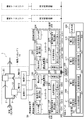
- FIG. 1 is a block diagram showing a configuration of a bearing system according to an embodiment of the present invention.
- FIG. 2 is a sectional view showing the structure of the bearing.
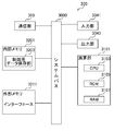
- FIG. 3 is a configuration diagram of hardware of the control unit 300.
- FIG. 4 is a configuration diagram of hardware of the measurement execution unit 100.
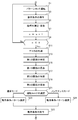
- FIG. 5 is a flowchart showing the operation of the bearing system of the embodiment.
- FIG. 6 is a partially developed view of the flowchart of FIG.
- FIG. 7 is a partial development of the flowchart of FIG.
- FIG. 1 shows the configuration of a bearing system 1 according to an embodiment of the present invention.
- the bearing system 1 controls bearings of a generator installed in a hydroelectric power plant.
- FIG. 1 uses an example in which two power generators are used in a hydroelectric power plant for ease of explanation.
- the bearing system 1 includes a bearing assembly 10 and a site control device 50 installed at the site of a hydroelectric power plant, a control unit 300 as a server connected to the site control device 50 as a client via the Internet or a dedicated communication line. It has.
- the bearing assembly 10 includes two bearings (bearing A11 and bearing B21).
- the bearings A11 and B21 are of a vertical type, and slide the shafts A12 and B22, which are rotors of the generator, respectively. It is movably supported.
- the water from the dam is diverted to two branches 2,3.
- the propeller 13 of the shaft A12 and the propeller 23 of the shaft B22 receive the flowing water of each of the branch passages 2 and 3, and rotate the shafts 12 and 22.
- the bearing means a bearing device (also referred to as a bearing unit) provided with ancillary equipment in addition to a sliding portion such as a pad.
- the field controller 50 includes a measurement execution unit A100 and a measurement execution unit B200.
- the measurement execution unit A100 is connected to the bearing A11.
- the measuring unit A101 measures the temperature on the back surface of the bearing A11 in order to identify the loss as the first index.
- a resistance thermometer type thermometer such as an RTD or a thermocouple type thermometer can be used.
- the temperature measured in this way is sent to the loss calculator 1101 of the controller 110.
- the loss calculator 1101 calculates the loss of the bearing A from the temperature of the bearing A based on a predetermined rule.
- the calculated loss of the bearing A is stored in the first area 1081 of the index storage unit A108 together with the temperature measurement time.
- the measurement execution unit A100 may store the temperature data state in the first area 1081 without calculating the loss. The calculation can also be performed by the control unit 300.
- the measurement unit A101 also measures the thickness of the bearing A11 as a second index to specify the degree of progress of wear of the bearing.
- An optical sensor can be used for this measurement.
- the measured thickness of the bearing A11 is stored in the second area 1082 of the index storage unit A108 together with the measurement time.
- the value obtained by dividing the change in thickness by the elapsed time indicates the degree of progress of wear.
- the operating condition execution unit A103 adjusts the temperature of the lubricating oil supplied to the bearing A11.
- FIG. 2 shows the bearing A11.
- reference numeral 12 denotes an axis A
- a fan 15 is attached to the axis A12.
- the bearing A11 having a thrust type sliding portion includes a plurality of divided thrust pads (hereinafter, also referred to as pads) 16, and the surface of the pads 16 is supplied with lubricating oil. This lubricating oil is circulated between the radiator 17 and the pad 16.
- the thrust pad 16 is supported by an actuator (not shown) that can receive a signal from the operation condition execution unit A103, can adjust the distance of the shaft A12 from the thrust collar, and can select a sliding contact mode or a separation mode.
- the measurement unit A101 measures the thickness of the pad 16. Wear of the pad 16 of the bearing A11 can also be adjusted by controlling the distance between the thrust collar of the shaft A12 and the pad 16 of the bearing A11 by a jacking mechanism.
- the operation condition execution unit A103 sends a signal for adjusting the fan angle of the fan 15 that rotates together with the axis A12.
- the angle adjusting device 19 receives this signal and changes the angle of the fan 15.
- the wind of the fan 15 is sent to the radiator 17. That is, the air volume of the fan 15 depends on the angle of the fan 15, and the cooling capacity of the radiator 17 for lubricating oil is adjusted by the air volume.
- the output signal of the operation condition execution unit A103 can be directly specified from the input / output unit 104 provided in the measurement execution unit A100, or can be specified by remote control from the control unit 300.
- the operation condition execution unit A103 can also send a signal for selecting the mode (sliding mode, separation mode) to the actuator supporting the thrust pad 16.
- the operating condition execution unit A103 may adjust both the angle of the fan 15 (that is, the temperature of the lubricating oil) and the number of thrust pads 16 (that is, the sliding area of the bearing).
- the input / output unit 104 includes an input device such as a keyboard and a pointer, and an output device such as a display and a printer.
- the operator can also send a command signal to the operation condition execution unit A103 via the input device, and the operation condition execution unit A103 outputs a signal value corresponding to the command signal. Then, the value of the signal can be stored in the first area 1071 of the execution operation condition storage unit A107 in the memory device 106.
- Reference numeral 109 denotes a communication unit, which serves as a communication interface of the measurement execution unit A100.
- An instruction signal to the operation condition execution unit A103 is sent from the control unit 300 via the communication unit 109. Also in this case, the content of the instruction signal can be stored in the first area 1071 of the execution operation condition storage unit A107.
- a controller 110 is a general-purpose computer device.
- the control program of the controller 110 is also stored in the memory device 106. It is possible to omit an area for storing data relating to the measured index and data relating to the operating condition in the memory device 106, and to perform the function in a predetermined area of the memory device 320 of the control unit 300.
- the measurement execution unit B200 is connected to the bearing B21.
- the operation of each element of the measurement execution unit B200 is the same as the operation of each element of the measurement execution unit A100 except that the target is the bearing B21. Therefore, each element performing the same operation as the element of the measurement execution unit A100 is given the same reference numeral in the lower two digits, and description thereof is omitted.
- the control unit 300 is remote from the hydroelectric power station and is connected to the measurement execution unit A and the measurement execution unit B via the Internet.
- the communication unit 309 serves as a communication interface for that.
- the first operation condition A of the bearing A11 stored in the first area 1071 of the execution operation condition storage unit A107 (the operation condition executed by the bearing A11 by the operation condition execution unit A103)
- the first operation condition B of the bearing B21 stored in the first area 2071 of the execution operation condition storage unit B207 (the operation condition execution unit B203 was executed by the bearing B21).
- the first instruction storage unit 321 stores the data of the lubricating oil temperature A and the time to be supplied to the bearing A11 as the first operating condition A of the bearing A11, and the data of the bearing A11 when the first operating condition A is executed.
- the data of the loss A and the time of the bearing A11 as the obtained first index A, the data of the lubricating oil temperature B and the time supplied to the bearing B21 as the first operating condition B of the bearing B21, and the first operating condition B The loss and time data of the bearing B21 as the first index B obtained by the bearing B21 when executed are stored. These data sets are created, for example, for each pattern in Table 1, and are stored in the first instruction storage unit 321.
- the first specifying unit 311 of the controller 310 uses the bearing A11 under the first operating condition A and the bearing B21 under the first operating condition B for each pattern from each data set stored in the first instruction storage unit 321.
- the relationship between the lubricating oil temperature A to be supplied to the bearing A11, the lubricating oil temperature B to be supplied to the bearing B21, the loss (average value) of the bearing A11, and the loss (average value) of the bearing B21 when operated for 20 days is specified. I do.
- the lubricating oil to be supplied to each bearing is supplied at the temperature specified in each pattern and the bearing back surface temperature measured at the time closest to that time (preferably the same time). Are determined, and their average is calculated.
- the relationship specified by the first specifying unit 311 is stored in the first relationship storage unit 323 as a first relationship. That is, the first relation storage unit 323 stores, for each pattern of the first operating condition A and the first operating condition B, the temperature as the operating condition and the bearing A11 and the bearing B21 when the operating condition is executed. The average loss, which is an indicator, is stored.
- the second instruction storage unit 325 stores lubricating oil temperature A and time data to be supplied to the bearing A11 as the first operating condition A of the bearing A11, and data obtained by the bearing A11 when the first operating condition A is executed.
- the data of the thickness A and the time of the bearing A11 as the second index A, the data of the lubricating oil temperature B and the time supplied to the bearing B21 as the first operating condition B of the bearing B21, and the first operating condition B were executed.
- the data of the thickness of the bearing B21 and the time as the second index B obtained at the time of the bearing B21 are sometimes stored. These data sets are created, for example, for each pattern in Table 2, and are stored in the second instruction storage unit 325.
- the second specifying unit 315 of the controller 310 uses the bearing A11 under the first operating condition A and the bearing B21 under the first operating condition B for each pattern. For example, the relationship between the temperature A of the lubricating oil supplied to the bearing A11 and the temperature B of the lubricating oil supplied to the bearing B21, the degree of progress of wear of the bearing A11, and the degree of progress of wear of the bearing B when operated for 20 days is specified.
- the wear progress degree of each bearing is calculated from the difference between the bearing thickness at the start of the operation condition and the bearing thickness at the end of the operation condition.
- the relationship between the calculation result, that is, the degree of progress of wear of each bearing and the temperature of the lubricating oil supplied to each bearing specified by the pattern is specified. It is desirable that the temperature of the lubricating oil supplied to each bearing be maintained for a predetermined period (20 days in this example) to calculate the degree of progress of wear.
- the relation specified by the second specifying unit 315 is stored in the second relation storage unit 327 as a second relation. That is, the second relation storage unit 327 stores, for each pattern of the first operating condition A and the first operating condition B, the degree of wear progress as an index in the bearing A11 and the bearing B21 together with the temperature as the operating condition. You.
- Reference numeral 304 denotes an input / output unit, which includes an input device such as a keyboard and a pointer and an output device such as a display and a printer.
- the operator can monitor the use state (loss, bearing thickness) of the bearing A11 and the use state (loss, bearing thickness) of the bearing B21 at the site via the monitor. It is also possible to monitor the output of a sensor mounted on the sliding part and support part of the bearing, the auxiliary equipment of the bearing, and the generator itself from a remote place.
- the first control unit 313 sends a command signal to the operation condition execution unit A103 of the measurement execution unit A100.
- the operating condition execution unit A103 can execute an instruction of the operator via the input / output unit 304 to the bearing A11 by remote control in accordance with the command signal.
- the controller 310 is a general-purpose computer that controls each element of the control unit 300, and its control program is stored in the memory device 320.
- FIG. 3 shows a hardware configuration of the control unit 300.
- the control unit 300 includes a general computer device in which a communication unit 309, an input unit 3041, an output unit 3043, an operation unit 3101, an internal memory 3201, and an external memory interface 3211 are connected by a system bus 3000.
- the communication unit 309 is an interface for inputting and outputting data to and from an external communication line, and operates according to a general-purpose communication protocol.
- the input unit 3041 includes a general input device such as a keyboard and a pointer.
- the output unit 3043 includes a printer, a display, and the like.
- the arithmetic unit 3101 includes a CPU 3103, a ROM 3105, and a RAM 3107, functions as a first specifying unit 311, a first control unit 313, a second specifying unit 315, and a second control unit 317, and controls the entire system of the control unit 300.
- the ROM 3105 includes a non-volatile memory in which a control program for controlling the arithmetic unit 3101 and the like are stored.
- the RAM 3107 rewritably stores various parameters and the like set in advance by an operator via the input unit 3041, and provides a working area to the CPU 3103.
- the control program for controlling the arithmetic unit 3101 is not limited to the ROM 3105, and may be stored in the RAM 3107 or the internal memory 3201.
- the internal memory 3201 can adopt an HDD type or an SSD type.
- the control data storage section 3203 of the internal memory 3201 is used as a first instruction storage section 321, a first relation storage section 323, a second instruction storage section 325, and a second relation storage section 327.
- the RAM 3107 of the arithmetic unit 3101 can be used as a so-called buffer memory for temporarily storing data.
- Reference numeral 3211 denotes an external memory interface through which an external memory (USB memory, hard disk memory, or the like) is detachably attached.
- FIG. 4 shows a hardware configuration of the measurement execution unit A100.
- the measurement execution unit A100 connects the communication unit 109, the input unit 1041, the output unit 1043, the calculation unit 1111, the internal memory 1061, the external memory interface 1065, the temperature sensor 1011, the optical sensor 1013, and the fan angle driver 1301 via the system bus 1000.
- it comprises a general computer device.
- the communication unit 109 is an interface for inputting and outputting data to and from an external communication line, and operates according to a general-purpose communication protocol.
- the input unit 1041 includes a general input device such as a keyboard and a pointer.
- the output unit 1043 includes a printer, a display, and the like.
- the calculation unit 1111 includes a CPU 1113, a ROM 1115, and a RAM 1117, and can also function as a loss calculation unit 1101, and controls the entire system of the measurement execution unit 100.
- the ROM 1115 includes a nonvolatile memory in which a control program for controlling the arithmetic unit 1111 and the like are stored.
- the RAM 1117 rewritably stores various parameters and the like set in advance by an operator via the input unit 1041, and provides a working area to the CPU 1113.
- a control program for controlling the arithmetic unit 1111 is not limited to the ROM 1115, and may be stored in the RAM 1117 or the internal memory 1061.
- the internal memory 1061 can adopt an HDD type or an SSD type.
- the control data storage unit 1063 of the internal memory 1061 is used as the execution operation condition storage unit A107 and the index storage unit A108.
- the RAM 1117 of the arithmetic unit 1111 can be used as a so-called buffer memory for temporarily storing data.
- Reference numeral 1065 denotes an external memory interface through which an external memory (USB memory, hard disk memory, or the like) is detachably attached.
- the temperature sensor 1011 and the optical sensor 1013 function as a measurement unit A101, and measure the temperature of the back surface (anti-sliding surface) of the pad 16 of the bearing A11 and the thickness of the pad 16, respectively.
- the fan angle driver 1301 sends a command signal to the angle adjusting device 19 as the operating condition execution unit A103 so as to change the angle of the fan 15 that rotates with the axis A12.
- the bearings A11 and B21 are operated under the rated operating conditions (lubricating oil temperature supplied to the sliding parts of the bearings) in the first place (step S1).
- the rated operating condition of the bearing A11 (the lubricating oil temperature supplied to the sliding portion of the bearing) is stored in the first area 1071 of the execution operating condition storage unit A107 together with the execution time
- the rated operating condition of the bearing B21 (bearing The lubricating oil temperature to be supplied to the sliding section is stored in the first area 2071 of the execution condition storage section B207 together with the execution time (step S3). Operation under the rated conditions shall be performed continuously for 20 days.
- step S5 each loss (first index) and degree of wear progress (second index) of the bearings A11 and B21 when the test operation under the conditions of step S1 (pattern # 1, see Tables 1 and 2) was performed. ) Are measured and stored.
- the loss A of the bearing A11 is specified at a predetermined interval (for example, 12 hours) from the start of the pattern # 1 (step S51).
- the loss A is specified by converting the value of the temperature of the bearing A11 (the back surface temperature of the bearing A11) measured by the measuring unit A101 into the value of the loss by the loss calculating unit 1101.
- the loss A is stored in the first area 1081 of the index storage unit A108 together with the time at the time of temperature measurement (step S52).
- the loss B of the bearing B21 is specified (Step S53).
- the loss B is specified by converting the value of the temperature of the bearing B21 (the rear surface temperature of the bearing B21) measured by the measuring unit B201 into a loss value by the loss calculating unit 2101. It is stored in the first area 2081 of the index storage unit B208 together with the time of measurement (step S54).
- step S55 the thickness of the pad of the bearing A11 is measured by the measuring unit A101.
- the measurement result is stored in the second area 1082 of the index storage unit A108 together with the measurement time (step S56).
- step S57 the thickness of the pad of the bearing B21 is measured by the measurement unit B201 (step S57), and the result is stored in the second area 2082 of the index storage unit B208 together with the measurement time (step S58).
- the degree of wear of the pads of each bearing can be specified.
- the thickness of the pad can be measured at predetermined intervals during the test operation, and can be stored in each index storage unit together with the measurement time. Thereby, an index (in this example, a change in the thickness of the pad) indicating the use state of each bearing can be obtained more accurately.
- steps S3 and S5 are repeated for each pattern shown in Tables 1 and 2 (Steps S7 and S9).
- the setting of the temperature of the lubricating oil supplied to the sliding portion of the bearing as an operating condition is performed by changing the angle of the fan 15.
- a temperature sensor (not shown) is attached to, for example, the outlet of the radiator 17 so that the lubricating oil temperature is always. It goes without saying that the angle of the fan 15 can be automatically or manually controlled so as to be the set value of the operating condition.
- test operation when the loss of the bearing A and / or the bearing B becomes equal to or more than the threshold value, it is preferable that the test operation be forcibly terminated. In such a case, it is preferable that the control unit 300 or the controllers 110 and 210 control the operation condition execution unit A103 and the operation condition execution unit B203 so that the operation in the pattern is not performed.
- step S11 the data stored in the memory device 106 and the memory device 206 is sent to the memory device 320 of the control unit 300 via the communication line.
- data obtained after executing all the patterns is transmitted.
- communication can be performed every time data is obtained by executing each pattern.
- the first operating condition A of each pattern stored in the first area 1071 of the execution operating condition storing unit A107 (that is, the lubricating oil temperature A supplied to the sliding portion of the bearing A11) And the measurement time) are sent to the first instruction storage unit 321 and the second instruction storage unit 325 (step S111).
- the first operation condition B (that is, the lubricating oil temperature B supplied to the sliding portion of the bearing B21 and the measurement time thereof) of each pattern stored in the first area 2071 of the execution operation condition storage unit B207 is indicated by the first instruction. It is sent to the storage unit 321 and the second instruction storage unit 325 (Step S112).
- the first index A (that is, the loss A of the bearing A11 and the measurement time) of each pattern stored in the first area 1081 of the index storage unit A108 is sent to the first instruction storage unit 321 (step S113).
- the first index B of each pattern stored in the first area 2081 of the index storage unit B208 (that is, the loss B of the bearing B21 and its measurement time) is sent to the first instruction storage unit 321 (Step S114).
- the second index A (that is, the thickness A of the bearing A11 and the measurement time thereof) stored in the second area 1082 of the index storage unit A108 is sent to the second instruction storage unit 325 (step S115), and the index storage is performed.
- the second index B (that is, the thickness B of the bearing B21 and the measurement time thereof) stored in the second area 2082 of the part B208 is sent to the second instruction storage part 325 (Step S116).
- the bearing system is controlled using the lubricating oil temperature as the first operation condition
- a condition different from the first operating condition for example, a flow rate of the lubricating oil supplied to the sliding portion of the bearing or a total sliding area may be used.
- the second operation condition is stored in the execution operation condition storage unit similarly to the first operation condition. More specifically, the second operation condition A for the bearing A11 is stored in the second area 1072 of the execution operation condition storage unit A107. Similarly, the second operation condition B for the bearing B21 is stored in the second area 2072 of the execution operation condition storage unit B207.
- the first specifying unit 311 determines the operating condition A and the operating condition B of each pattern stored in the first instruction storage unit 321 and the loss of the bearing A11 and the loss of the bearing B21 at that time. A set relation (first relation) with the loss is specified.
- the first specifying unit 311 obtains the bearing A11 and the bearing B21 from the data set of the lubricating oil temperature and the loss of each bearing stored in the first instruction storage unit 321 and the time when these were measured. The relationship between the calculation result of each loss (average) and the lubricating oil temperature is specified.
- step S15 the first relations thus obtained are put together in a table format (see Table 1) and stored in the first relation storage unit 323.
- step S17 the second specifying unit 315 compares the operating condition A and the operating condition B of each pattern stored in the second instruction storage unit 325 with the progress of wear of the bearing A11 and the progress of wear of the bearing B21 at that time.
- a set relation (second relation) is specified.
- the second specifying unit 315 obtains the bearing A11 and the bearing A11 from the data set of the lubricating oil temperature and the pad thickness of each bearing stored in the second instruction storage unit 325 and the time when these were measured.
- the relationship between the calculation result of each pad wear amount (degree of progress) of B21 and the lubricating oil temperature is specified.
- step S19 the second relations thus obtained are put together in a tabular form (see Table 2) and stored in the second relation storage unit 327.
- the first relation stored in the first relation storage unit 323 and the second relation stored in the second relation storage unit 327 can be output through the input / output unit 304.
- the control unit 300 causes the first control unit 313 to determine the operating condition with the least loss from the first relation stored in the first relation storage unit 323.
- a pattern is selected, and the operation condition is sent to the operation condition execution unit A103 and the operation condition execution unit B203 of the site control device 50 (step S23).
- the operation condition execution units A103 and B203 which are operation condition execution units, execute the transmitted operation conditions, that is, adjust the fan angle and specify the lubricating oil temperature in each pattern. (Step S25).
- the control unit 300 selects the second control unit 317 from the second relation stored in the second relation storage unit 327, for example, by the operator or the AI.
- a pattern of the operating condition that causes the progress of the wear of the bearing to be delayed is selected, and the operating condition is transmitted to the operating condition executing unit A103 and the operating condition executing unit B203 of the on-site controller 50 (step S24).
- the operation condition execution units A103 and B203 which are operation condition execution units, execute the transmitted operation conditions. That is, it is assumed that the fan angle is adjusted and the lubricating oil temperature is specified in each pattern (step S25).
- An instruction can be issued to the on-site control device 50 so that each control device on the control unit 300 side automatically selects a pattern according to the operation mode and executes the operation condition.
- the controller 310 performs each operation in which the bearing A11 and the bearing B21 execute the performance required for the bearing system 1 from the first relation and the second relation stored in the first relation storage unit 323 and the second relation storage unit 327, respectively. It is also possible to select a condition and send each operation condition to the operation condition execution unit A103 and the operation condition execution unit B203 of the site controller 50 via the communication unit 309.
- the operating conditions at that time can be stored in the memory device 320.
- the operator can manually select a pattern via the input / output unit 304. In this case, the operation condition of the selected pattern is sent from the control unit 300 to each of the operation condition execution units 103 and 203 of the site controller 50, and the operation condition is executed.
- the operator who has selected the pattern may directly input the operation condition of the pattern to the operation condition execution unit A103 and the operation condition execution unit B203 via the input / output units 104 and 204 of the site control device 50.
- each operating condition for example, lubricating oil temperature supplied to the bearing
- each index for example, loss and wear progress of the bearing
- the comparison is made with the first relation and the second relation stored in the first relation storage section 323 and the second relation storage section 327.
- the first relation and the second relation can be updated to new first relations and second relations, and an optimum one can be selected from data stored in the memory device 320, or a new optimum relation can be determined by the AI.
- the measured indices related to each bearing and the data related to the executed operating conditions are sent from each on-site control device serving as a client to a control unit serving as a server. Is specified, and data relating to the specified relationship is sent from the control unit to each site control device, and the operating condition execution unit of each site control device causes each bearing to execute each operating condition.
- the bearing system may include a plurality of bearing assemblies and a plurality of on-site controllers.
- an example is a bearing system in which a plurality of factories in which a plurality of bearings are installed are connected by a communication line.
- the bearing assembly may have a form in which a plurality of bearings (sliding portions) support a common shaft.
- an example is a bearing assembly having two bearings (sliding portions) on one shaft.
- a site controller is provided at each hydropower station and this is used as a client, and these are used as communication lines. It is preferable to connect to a control unit serving as a server via the server and accumulate data in the control unit serving as a server. The same applies when assuming a large number of factories.
- the controller sends instructions to all or a plurality of selected on-site control devices to control those bearings, That is, the generator and the pump can be set to the emergency operation mode.
Landscapes
- Engineering & Computer Science (AREA)
- General Engineering & Computer Science (AREA)
- Mechanical Engineering (AREA)
- Physics & Mathematics (AREA)
- General Physics & Mathematics (AREA)
- Fluid Mechanics (AREA)
- Chemical & Material Sciences (AREA)
- Analytical Chemistry (AREA)
- Sliding-Contact Bearings (AREA)
- Testing Of Devices, Machine Parts, Or Other Structures Thereof (AREA)
- Mounting Of Bearings Or Others (AREA)
- Rolling Contact Bearings (AREA)
Priority Applications (4)
| Application Number | Priority Date | Filing Date | Title |
|---|---|---|---|
| GB2018307.5A GB2588009C (en) | 2018-07-12 | 2019-07-05 | Bearing system, bearing system control method, and computer program for controlling bearing system |
| US17/059,832 US11391325B2 (en) | 2018-07-12 | 2019-07-05 | Bearing system, bearing system control method, and computer program for controlling bearing system |
| KR1020207034071A KR102500717B1 (ko) | 2018-07-12 | 2019-07-05 | 베어링 시스템, 베어링 시스템의 제어 방법, 및 베어링 시스템을 제어하기 위한 컴퓨터 프로그램을 기록한 컴퓨터 판독 가능한 기록 매체 |
| DE112019003542.8T DE112019003542B4 (de) | 2018-07-12 | 2019-07-05 | Lagersystem, Lagersystemsteuerungsverfahren und Computerprogramm zur Steuerung des Lagersystems |
Applications Claiming Priority (2)
| Application Number | Priority Date | Filing Date | Title |
|---|---|---|---|
| JP2018-132137 | 2018-07-12 | ||
| JP2018132137A JP6718926B2 (ja) | 2018-07-12 | 2018-07-12 | 軸受システム、軸受システムの制御方法、及び軸受システムを制御するためのコンピュータプログラム |
Publications (1)
| Publication Number | Publication Date |
|---|---|
| WO2020013099A1 true WO2020013099A1 (ja) | 2020-01-16 |
Family
ID=69141663
Family Applications (1)
| Application Number | Title | Priority Date | Filing Date |
|---|---|---|---|
| PCT/JP2019/026903 Ceased WO2020013099A1 (ja) | 2018-07-12 | 2019-07-05 | 軸受システム、軸受システムの制御方法、及び軸受システムを制御するためのコンピュータプログラム |
Country Status (6)
| Country | Link |
|---|---|
| US (1) | US11391325B2 (https=) |
| JP (1) | JP6718926B2 (https=) |
| KR (1) | KR102500717B1 (https=) |
| DE (1) | DE112019003542B4 (https=) |
| GB (1) | GB2588009C (https=) |
| WO (1) | WO2020013099A1 (https=) |
Families Citing this family (1)
| Publication number | Priority date | Publication date | Assignee | Title |
|---|---|---|---|---|
| US12305803B1 (en) * | 2024-04-02 | 2025-05-20 | Hornche Corporation | Ai-driven wireless lubricator remote control system |
Citations (4)
| Publication number | Priority date | Publication date | Assignee | Title |
|---|---|---|---|---|
| US6886985B1 (en) * | 2000-09-29 | 2005-05-03 | Reliance Electric Technologies, Llc | Auxiliary fan cooling of bearing housings |
| WO2008050470A1 (en) * | 2006-10-27 | 2008-05-02 | Ntn Corporation | Preload adjustment method and device for rolling bearing |
| JP2015203393A (ja) * | 2014-04-16 | 2015-11-16 | Ntn株式会社 | 状態監視システム |
| JP2016056921A (ja) * | 2014-09-11 | 2016-04-21 | 株式会社東芝 | 軸受アライメント調整装置および軸受アライメント調整方法 |
Family Cites Families (15)
| Publication number | Priority date | Publication date | Assignee | Title |
|---|---|---|---|---|
| US3246640A (en) * | 1964-04-29 | 1966-04-19 | Robertshaw Controls Co | Bearing temperature and wear sensing device |
| DE2827993C2 (de) | 1978-06-26 | 1985-03-14 | Pfister Gmbh, 8900 Augsburg | Radial nachstellbare hydrostatische Radiallagerstelle für rotierende Teile |
| JPS5557723A (en) * | 1978-10-24 | 1980-04-28 | Fuji Electric Co Ltd | Automatic load adjusting horizontal bearing |
| US4643592A (en) | 1984-11-09 | 1987-02-17 | Lewis David W | Vibration limiting of rotating machinery through active control means |
| JP2001297973A (ja) | 2000-04-14 | 2001-10-26 | Canon Inc | 位置決め装置 |
| DK178172B1 (en) * | 2010-05-07 | 2015-07-20 | Man Diesel & Turbo Deutschland | Improved monitoring of wear of bearings in a large two stroke diesel engine |
| CN102252843B (zh) | 2011-07-21 | 2013-01-09 | 河南科技大学 | 一种滚动轴承性能变异的评估方法 |
| CN102562783B (zh) | 2012-01-11 | 2013-11-06 | 西安交通大学 | 由可控可倾瓦块和承载瓦块构成的一种变性能径向轴承 |
| KR20160002686A (ko) | 2013-04-26 | 2016-01-08 | 술저 매니지멘트 에이지 | 터보기계의 모듈의 마모 상태를 평가하기 위한 방법, 모듈 및 터보기계 |
| DE102014200712A1 (de) | 2014-01-16 | 2015-07-16 | Schaeffler Technologies AG & Co. KG | Hydrodynamisches Gleitlager und Verfahren zur Betriebszustandsüberwachung eines hydrodynamischen Gleitlagers |
| US20170081009A1 (en) * | 2014-05-19 | 2017-03-23 | Propulsion Software Ab | Method and arrangement for continuous alignment of a rotating shaft |
| JP2016153669A (ja) | 2015-02-20 | 2016-08-25 | Ntn株式会社 | 潤滑油供給ユニットおよび軸受装置 |
| RU166258U1 (ru) * | 2016-03-09 | 2016-11-20 | федеральное государственное бюджетное образовательное учреждение высшего образования "Тюменский государственный университет" | Устройство для определения технического состояния подшипника скольжения гидромашины |
| GB2548877B (en) * | 2016-03-31 | 2020-08-05 | Mahle Int Gmbh | Engine bearing oil flow control method and control apparatus |
| JP2018076929A (ja) * | 2016-11-10 | 2018-05-17 | 三菱自動車工業株式会社 | 軸受 |
-
2018
- 2018-07-12 JP JP2018132137A patent/JP6718926B2/ja active Active
-
2019
- 2019-07-05 DE DE112019003542.8T patent/DE112019003542B4/de active Active
- 2019-07-05 US US17/059,832 patent/US11391325B2/en active Active
- 2019-07-05 KR KR1020207034071A patent/KR102500717B1/ko active Active
- 2019-07-05 WO PCT/JP2019/026903 patent/WO2020013099A1/ja not_active Ceased
- 2019-07-05 GB GB2018307.5A patent/GB2588009C/en active Active
Patent Citations (4)
| Publication number | Priority date | Publication date | Assignee | Title |
|---|---|---|---|---|
| US6886985B1 (en) * | 2000-09-29 | 2005-05-03 | Reliance Electric Technologies, Llc | Auxiliary fan cooling of bearing housings |
| WO2008050470A1 (en) * | 2006-10-27 | 2008-05-02 | Ntn Corporation | Preload adjustment method and device for rolling bearing |
| JP2015203393A (ja) * | 2014-04-16 | 2015-11-16 | Ntn株式会社 | 状態監視システム |
| JP2016056921A (ja) * | 2014-09-11 | 2016-04-21 | 株式会社東芝 | 軸受アライメント調整装置および軸受アライメント調整方法 |
Also Published As
| Publication number | Publication date |
|---|---|
| GB2588009B (en) | 2022-09-14 |
| JP6718926B2 (ja) | 2020-07-08 |
| GB2588009A8 (en) | 2022-10-19 |
| DE112019003542B4 (de) | 2026-03-12 |
| GB2588009A (en) | 2021-04-14 |
| US11391325B2 (en) | 2022-07-19 |
| DE112019003542T5 (de) | 2021-03-25 |
| JP2020008149A (ja) | 2020-01-16 |
| GB2588009C (en) | 2023-02-01 |
| GB2588009B8 (en) | 2022-10-19 |
| GB202018307D0 (en) | 2021-01-06 |
| KR102500717B1 (ko) | 2023-02-17 |
| KR20210002653A (ko) | 2021-01-08 |
| US20210215204A1 (en) | 2021-07-15 |
Similar Documents
| Publication | Publication Date | Title |
|---|---|---|
| CN113153794B (zh) | 基于云计算的风机在线监测方法、装置及系统 | |
| US10724499B2 (en) | Controlling wind turbines according to reliability estimates | |
| KR20160017681A (ko) | 풍력플랜트 관리 시스템 및 그 방법 | |
| JP2007538234A (ja) | ガスタービンエンジン運転を監視する方法 | |
| JP6805912B2 (ja) | 評価装置、評価システム、および評価方法 | |
| JP5672099B2 (ja) | 電子機器を搭載した装置、電子機器を搭載した装置の冷却プログラム及び電子機器を搭載した装置の冷却方法 | |
| CN113312730B (zh) | 一种双驱汽轮机转子应力监测方法 | |
| CN101975436A (zh) | 空调系统水侧设备节能控制方法 | |
| CN108108577A (zh) | 一种水泵叶片疲劳寿命预测及其与导叶最优间距确定方法 | |
| JP6718926B2 (ja) | 軸受システム、軸受システムの制御方法、及び軸受システムを制御するためのコンピュータプログラム | |
| CN110162890B (zh) | 大型立式电机推力轴承轴瓦运行温度预测与最小需要冷却水流量确定方法 | |
| CN118250982A (zh) | 一种两相冷板液冷系统及方法 | |
| EP3394437B1 (en) | Method and system of operating a wind turbine farm | |
| JP7034202B2 (ja) | 軸受システム、軸受システムの制御方法、及び軸受システムを制御するためのコンピュータプログラム | |
| CN110083962B (zh) | 一种离心泵主轴运行寿命的预测方法及预测系统 | |
| CN107545355B (zh) | 一种故障原因诊断方法和装置 | |
| JP5600085B2 (ja) | 評価支援システム、方法およびプログラム | |
| EP2871459B1 (en) | Turbomachine airfoil erosion determination | |
| Blinov et al. | Estimating the Influence of Compressor Blade Erosion Wear on the Compressor’s Integral and Local Characteristics | |
| US12429002B2 (en) | Load adjustment method, load adjustment device, and program | |
| CN112926801B (zh) | 一种基于分位数回归的负荷曲线组合预测方法及装置 | |
| CN113586323B (zh) | 非稳态水轮发电机组开机顺序确定方法、装置及存储介质 | |
| KR20230092322A (ko) | 플랜트의 단열재 설계 최적화 방법 및 그 시스템 | |
| Ray et al. | Cement plant fan efficiency upgrades | |
| JP6381282B2 (ja) | 異常検出装置及びプログラム |
Legal Events
| Date | Code | Title | Description |
|---|---|---|---|
| 121 | Ep: the epo has been informed by wipo that ep was designated in this application |
Ref document number: 19834974 Country of ref document: EP Kind code of ref document: A1 |
|
| ENP | Entry into the national phase |
Ref document number: 202018307 Country of ref document: GB Kind code of ref document: A Free format text: PCT FILING DATE = 20190705 |
|
| WWE | Wipo information: entry into national phase |
Ref document number: 2018307.5 Country of ref document: GB |
|
| ENP | Entry into the national phase |
Ref document number: 20207034071 Country of ref document: KR Kind code of ref document: A |
|
| WWE | Wipo information: entry into national phase |
Ref document number: 112019003542 Country of ref document: DE |
|
| 122 | Ep: pct application non-entry in european phase |
Ref document number: 19834974 Country of ref document: EP Kind code of ref document: A1 |
|
| WWG | Wipo information: grant in national office |
Ref document number: 2018307.5 Country of ref document: GB |
|
| WWG | Wipo information: grant in national office |
Ref document number: 112019003542 Country of ref document: DE |