WO2020013022A1 - 反応器及びこれを備えた反応器システム - Google Patents
反応器及びこれを備えた反応器システム Download PDFInfo
- Publication number
- WO2020013022A1 WO2020013022A1 PCT/JP2019/026221 JP2019026221W WO2020013022A1 WO 2020013022 A1 WO2020013022 A1 WO 2020013022A1 JP 2019026221 W JP2019026221 W JP 2019026221W WO 2020013022 A1 WO2020013022 A1 WO 2020013022A1
- Authority
- WO
- WIPO (PCT)
- Prior art keywords
- raw material
- solvent
- material solution
- reaction
- reactor
- Prior art date
- Legal status (The legal status is an assumption and is not a legal conclusion. Google has not performed a legal analysis and makes no representation as to the accuracy of the status listed.)
- Ceased
Links
Images



Classifications
-
- B—PERFORMING OPERATIONS; TRANSPORTING
- B01—PHYSICAL OR CHEMICAL PROCESSES OR APPARATUS IN GENERAL
- B01J—CHEMICAL OR PHYSICAL PROCESSES, e.g. CATALYSIS OR COLLOID CHEMISTRY; THEIR RELEVANT APPARATUS
- B01J19/00—Chemical, physical or physico-chemical processes in general; Their relevant apparatus
- B01J19/0093—Microreactors, e.g. miniaturised or microfabricated reactors
-
- B—PERFORMING OPERATIONS; TRANSPORTING
- B01—PHYSICAL OR CHEMICAL PROCESSES OR APPARATUS IN GENERAL
- B01J—CHEMICAL OR PHYSICAL PROCESSES, e.g. CATALYSIS OR COLLOID CHEMISTRY; THEIR RELEVANT APPARATUS
- B01J14/00—Chemical processes in general for reacting liquids with liquids; Apparatus specially adapted therefor
-
- B—PERFORMING OPERATIONS; TRANSPORTING
- B01—PHYSICAL OR CHEMICAL PROCESSES OR APPARATUS IN GENERAL
- B01J—CHEMICAL OR PHYSICAL PROCESSES, e.g. CATALYSIS OR COLLOID CHEMISTRY; THEIR RELEVANT APPARATUS
- B01J19/00—Chemical, physical or physico-chemical processes in general; Their relevant apparatus
- B01J19/0006—Controlling or regulating processes
-
- B—PERFORMING OPERATIONS; TRANSPORTING
- B01—PHYSICAL OR CHEMICAL PROCESSES OR APPARATUS IN GENERAL
- B01J—CHEMICAL OR PHYSICAL PROCESSES, e.g. CATALYSIS OR COLLOID CHEMISTRY; THEIR RELEVANT APPARATUS
- B01J19/00—Chemical, physical or physico-chemical processes in general; Their relevant apparatus
- B01J19/0006—Controlling or regulating processes
- B01J19/0013—Controlling the temperature of the process
-
- B—PERFORMING OPERATIONS; TRANSPORTING
- B01—PHYSICAL OR CHEMICAL PROCESSES OR APPARATUS IN GENERAL
- B01J—CHEMICAL OR PHYSICAL PROCESSES, e.g. CATALYSIS OR COLLOID CHEMISTRY; THEIR RELEVANT APPARATUS
- B01J19/00—Chemical, physical or physico-chemical processes in general; Their relevant apparatus
- B01J19/24—Stationary reactors without moving elements inside
- B01J19/2415—Tubular reactors
-
- B—PERFORMING OPERATIONS; TRANSPORTING
- B01—PHYSICAL OR CHEMICAL PROCESSES OR APPARATUS IN GENERAL
- B01J—CHEMICAL OR PHYSICAL PROCESSES, e.g. CATALYSIS OR COLLOID CHEMISTRY; THEIR RELEVANT APPARATUS
- B01J19/00—Chemical, physical or physico-chemical processes in general; Their relevant apparatus
- B01J19/24—Stationary reactors without moving elements inside
- B01J19/2415—Tubular reactors
- B01J19/242—Tubular reactors in series
-
- B—PERFORMING OPERATIONS; TRANSPORTING
- B01—PHYSICAL OR CHEMICAL PROCESSES OR APPARATUS IN GENERAL
- B01J—CHEMICAL OR PHYSICAL PROCESSES, e.g. CATALYSIS OR COLLOID CHEMISTRY; THEIR RELEVANT APPARATUS
- B01J2219/00—Chemical, physical or physico-chemical processes in general; Their relevant apparatus
- B01J2219/00049—Controlling or regulating processes
- B01J2219/00051—Controlling the temperature
- B01J2219/00054—Controlling or regulating the heat exchange system
- B01J2219/00056—Controlling or regulating the heat exchange system involving measured parameters
- B01J2219/00058—Temperature measurement
- B01J2219/00063—Temperature measurement of the reactants
-
- B—PERFORMING OPERATIONS; TRANSPORTING
- B01—PHYSICAL OR CHEMICAL PROCESSES OR APPARATUS IN GENERAL
- B01J—CHEMICAL OR PHYSICAL PROCESSES, e.g. CATALYSIS OR COLLOID CHEMISTRY; THEIR RELEVANT APPARATUS
- B01J2219/00—Chemical, physical or physico-chemical processes in general; Their relevant apparatus
- B01J2219/00049—Controlling or regulating processes
- B01J2219/00164—Controlling or regulating processes controlling the flow
-
- B—PERFORMING OPERATIONS; TRANSPORTING
- B01—PHYSICAL OR CHEMICAL PROCESSES OR APPARATUS IN GENERAL
- B01J—CHEMICAL OR PHYSICAL PROCESSES, e.g. CATALYSIS OR COLLOID CHEMISTRY; THEIR RELEVANT APPARATUS
- B01J2219/00—Chemical, physical or physico-chemical processes in general; Their relevant apparatus
- B01J2219/00781—Aspects relating to microreactors
- B01J2219/00783—Laminate assemblies, i.e. the reactor comprising a stack of plates
-
- B—PERFORMING OPERATIONS; TRANSPORTING
- B01—PHYSICAL OR CHEMICAL PROCESSES OR APPARATUS IN GENERAL
- B01J—CHEMICAL OR PHYSICAL PROCESSES, e.g. CATALYSIS OR COLLOID CHEMISTRY; THEIR RELEVANT APPARATUS
- B01J2219/00—Chemical, physical or physico-chemical processes in general; Their relevant apparatus
- B01J2219/00781—Aspects relating to microreactors
- B01J2219/00788—Three-dimensional assemblies, i.e. the reactor comprising a form other than a stack of plates
- B01J2219/00792—One or more tube-shaped elements
-
- B—PERFORMING OPERATIONS; TRANSPORTING
- B01—PHYSICAL OR CHEMICAL PROCESSES OR APPARATUS IN GENERAL
- B01J—CHEMICAL OR PHYSICAL PROCESSES, e.g. CATALYSIS OR COLLOID CHEMISTRY; THEIR RELEVANT APPARATUS
- B01J2219/00—Chemical, physical or physico-chemical processes in general; Their relevant apparatus
- B01J2219/00781—Aspects relating to microreactors
- B01J2219/00801—Means to assemble
- B01J2219/0081—Plurality of modules
- B01J2219/00813—Fluidic connections
-
- B—PERFORMING OPERATIONS; TRANSPORTING
- B01—PHYSICAL OR CHEMICAL PROCESSES OR APPARATUS IN GENERAL
- B01J—CHEMICAL OR PHYSICAL PROCESSES, e.g. CATALYSIS OR COLLOID CHEMISTRY; THEIR RELEVANT APPARATUS
- B01J2219/00—Chemical, physical or physico-chemical processes in general; Their relevant apparatus
- B01J2219/00781—Aspects relating to microreactors
- B01J2219/00851—Additional features
- B01J2219/00867—Microreactors placed in series, on the same or on different supports
-
- B—PERFORMING OPERATIONS; TRANSPORTING
- B01—PHYSICAL OR CHEMICAL PROCESSES OR APPARATUS IN GENERAL
- B01J—CHEMICAL OR PHYSICAL PROCESSES, e.g. CATALYSIS OR COLLOID CHEMISTRY; THEIR RELEVANT APPARATUS
- B01J2219/00—Chemical, physical or physico-chemical processes in general; Their relevant apparatus
- B01J2219/00781—Aspects relating to microreactors
- B01J2219/00851—Additional features
- B01J2219/00869—Microreactors placed in parallel, on the same or on different supports
-
- B—PERFORMING OPERATIONS; TRANSPORTING
- B01—PHYSICAL OR CHEMICAL PROCESSES OR APPARATUS IN GENERAL
- B01J—CHEMICAL OR PHYSICAL PROCESSES, e.g. CATALYSIS OR COLLOID CHEMISTRY; THEIR RELEVANT APPARATUS
- B01J2219/00—Chemical, physical or physico-chemical processes in general; Their relevant apparatus
- B01J2219/00781—Aspects relating to microreactors
- B01J2219/00873—Heat exchange
-
- B—PERFORMING OPERATIONS; TRANSPORTING
- B01—PHYSICAL OR CHEMICAL PROCESSES OR APPARATUS IN GENERAL
- B01J—CHEMICAL OR PHYSICAL PROCESSES, e.g. CATALYSIS OR COLLOID CHEMISTRY; THEIR RELEVANT APPARATUS
- B01J2219/00—Chemical, physical or physico-chemical processes in general; Their relevant apparatus
- B01J2219/00781—Aspects relating to microreactors
- B01J2219/00891—Feeding or evacuation
-
- B—PERFORMING OPERATIONS; TRANSPORTING
- B01—PHYSICAL OR CHEMICAL PROCESSES OR APPARATUS IN GENERAL
- B01J—CHEMICAL OR PHYSICAL PROCESSES, e.g. CATALYSIS OR COLLOID CHEMISTRY; THEIR RELEVANT APPARATUS
- B01J2219/00—Chemical, physical or physico-chemical processes in general; Their relevant apparatus
- B01J2219/00781—Aspects relating to microreactors
- B01J2219/0095—Control aspects
- B01J2219/00952—Sensing operations
- B01J2219/00954—Measured properties
- B01J2219/00959—Flow
-
- B—PERFORMING OPERATIONS; TRANSPORTING
- B01—PHYSICAL OR CHEMICAL PROCESSES OR APPARATUS IN GENERAL
- B01J—CHEMICAL OR PHYSICAL PROCESSES, e.g. CATALYSIS OR COLLOID CHEMISTRY; THEIR RELEVANT APPARATUS
- B01J2219/00—Chemical, physical or physico-chemical processes in general; Their relevant apparatus
- B01J2219/00781—Aspects relating to microreactors
- B01J2219/0095—Control aspects
- B01J2219/00952—Sensing operations
- B01J2219/00954—Measured properties
- B01J2219/00961—Temperature
Definitions
- the present invention relates to a reactor for producing a target solution by mixing a plurality of types of raw material solutions and causing the raw material solutions to react with each other, and a reactor system including the same.
- Patent Document 1 discloses a method for nitrating an aromatic or heterocyclic aromatic compound by mixing an activated aromatic or heterocyclic aromatic compound and a nitrating agent in a microreactor. . Specifically, by mixing a solvent with the activated aromatic or heterocyclic aromatic compound and the nitrating agent, the concentration of the activated aromatic or heterocyclic aromatic compound and the nitrating agent is reduced. Lowering the temperature in the microreactor due to the heat of reaction generated by mixing the activated aromatic or heterocyclic aromatic compound with the nitrating agent. Is disclosed.
- Patent Document 1 a mixed raw material solution obtained by mixing a plurality of types of raw material solutions (in Patent Document 1, a mixed raw material solution comprising an activated aromatic or heterocyclic aromatic compound and a nitrating agent) Since the solvent is mixed with the mixed raw material solution to lower the concentration of the solution, the time required to generate the target solution becomes long.
- Patent Literature 1 also discloses that an activated aromatic or heterocyclic aromatic compound and a nitrating agent are mixed in the absence of a solvent. However, in such mixing, a mixed raw material solution is used. It is difficult to control the temperature of the mixed raw material solution because the concentration of a substance contributing to the reaction in step (1) is high and the reaction is easily promoted.
- An object of the present invention is a reactor for producing a target solution of interest by causing a reaction between the plural kinds of raw material solutions while flowing a mixed raw material solution containing plural kinds of raw material solutions mixed with each other. It is an object of the present invention to provide a reactor capable of suppressing an excessive rise in temperature of a mixed raw material solution while shortening a time required for generating a target solution, and a reactor system including the same.
- a reactor for producing a target solution by mixing and reacting a plurality of types of raw material solutions, and flowing a mixed raw material solution obtained by mixing the plurality of types of raw material solutions.
- a reaction flow path, and a solvent flow path through which a solvent that reduces the concentration of the raw material solution by dissolving in the mixed raw material solution is provided.
- the solvent flow path is such that the solvent flowing through the solvent flow path is the solvent. It is connected to the reaction channel between the upstream end and the downstream end of the reaction channel so that the mixed raw material solution flowing in the reaction channel is mixed from the middle of the reaction channel.
- FIG. 1 is a diagram illustrating a configuration of a reactor according to a first embodiment of the present invention and a reactor system including the same.
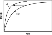
- 4 is a graph showing a relationship between a conversion rate and a reaction time when a plurality of types of raw material solutions are mixed and reacted using the reactor according to the first embodiment of the present invention.
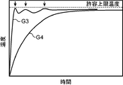
- 5 is a graph showing the relationship between the temperature of the mixed raw material solution and the reaction time when a plurality of types of raw material solutions are mixed and reacted using the reactor according to the first embodiment of the present invention.
- It is a schematic diagram showing a schematic configuration of a reactor according to a second embodiment of the present invention.
- FIG. 9 is a schematic diagram illustrating a configuration of a reactor according to a modified example of the second embodiment and a reactor system including the same.
- the reactor system RS includes the reactor 10 shown in FIG. 1, a raw material solution supply unit SS1, and a solvent supply unit SS2.
- the reactor 10 reacts the raw material containers with each other while flowing a mixed raw material solution having a plurality of types of raw material solutions mixed with each other, in this embodiment, two types of a first raw material solution RS1 and a second raw material solution RS2. By doing so, a desired target solution TS is generated.
- the reactor 10 includes a reaction channel 20 and a solvent channel 30.
- the reaction channel 20 allows a mixed raw material solution obtained by mixing the first and second raw material solutions RS1 and RS2, which are the plurality of types of raw material solutions, to flow.
- the reactor 10 according to this embodiment further includes a temperature control fluid channel adjacent to the reaction channel 20.
- a temperature control fluid flows through the temperature control fluid channel. The temperature control fluid is used to adjust the temperature of the mixed raw material solution such that the temperature of the mixed raw material solution flowing through the reaction channel 20 becomes a temperature suitable for the reaction of the mixed raw material solution.
- the reaction channel 20 includes a plurality of divided reaction channels 22 and a plurality of three-way tubes 24.
- the plurality of divided reaction channels 22 are arranged so as to be arranged in the longitudinal direction, that is, the direction in which the mixed solution of the first and second raw material solutions RS1 and RS2 flows.
- the plurality of three-way tubes 24 are respectively disposed between two adjacent divided reaction channels 22 among the plurality of divided reaction channels 22, and connect the two divided reaction channels 22 to each other.
- Each of the plurality of three-way tubes 24 has a mixed solution inlet, a solvent inlet, and a mixed solution outlet, and the mixed solution inlet is provided at a downstream end of the split reaction channel 22 on the upstream side of the three-way tube 24.
- the mixed solution outlet is connected to the upstream end of the split reaction channel 22 downstream of the three-way tube 24.
- a target solution storage tank 26 is connected to the downstream end of the reaction channel 20.
- the target solution storage tank 26 receives and stores the target solution TS generated by flowing the mixed raw material solution through the reaction channel 20.
- the raw material solution supply section SS1 includes a three-way pipe 28, a first raw material solution supply flow path 40, a first raw material solution storage tank 42, a first raw material solution supply pump 44, and a second raw material solution supply flow path 50. , A second raw material solution supply flow path 52 and a second raw material solution supply pump 54.
- the three-way tube 28 has an outlet connected to the upstream end of the reaction channel 20, and a first inlet and a second inlet on the opposite side.
- a first raw material solution storage tank 42 is connected to the first inlet via the first raw material solution supply channel 40, and the second inlet is connected to the second raw material solution via the second raw material solution supply channel 50 via the second raw material solution supply channel 50.
- the raw material solution storage tank 52 is connected.
- the first raw material solution supply flow path 40 allows the first raw material solution RS1 to flow
- the second raw material solution supply flow path 50 allows the second raw material solution RS2 to flow.
- the first and second raw material solutions RS1 and RS2 join in the three-way tube 28, whereby the mixed raw material solution in which the first raw material solution RS1 and the second raw material solution RS2 are mixed flows through the reaction channel 20. Flows.
- the first raw material solution storage tank 42 stores the first raw material solution RS1.
- the first raw material solution supply flow path 40 has a downstream end connected to the three-way tube 28 and an upstream end connected to the first raw material solution storage tank 42.
- the first raw material solution supply pump 44 is provided in the middle of the first raw material solution supply flow path 40, and converts the first raw material solution RS1 stored in the first raw material solution storage tank 42 into the first raw material solution. It operates so as to supply the reaction channel 20 through the supply channel 40 and the three-way tube 28.
- the second raw material solution storage tank 52 stores the second raw material solution RS2.
- the second raw material solution supply flow path 50 has a downstream end connected to the three-way pipe 28 and an upstream end connected to the second raw material solution storage tank 52.
- the second raw material solution supply pump 54 is provided in the middle of the second raw material solution supply flow path 50, and supplies the raw material solution RS2 stored in the second raw material solution storage tank 52 to the second raw material solution supply flow path. It operates to supply the reaction channel 20 through the channel 50 and the three-way tube 28.
- the solvent flow path 30 circulates the target solution TS as a solvent. That is, the solvent according to this embodiment is the target solution TS.
- the solvent supply section SS2 supplies the target solution TS as the solvent to the reaction flow path 20 through the solvent flow path 30, and the target solution storage tank 26 and a solvent provided in the solvent flow path 30 And a supply pump 36.
- the target solution TS supplied as a solvent dissolves in the mixed raw material solution, thereby suppressing an increase in the temperature of the mixed raw material solution due to a reaction in the mixed raw material solution.
- the solvent flow path 30 is connected to the upstream end of the reaction flow path 20 so that the target solution TS as a solvent is mixed with the mixed raw material solution flowing through the reaction flow path 20 from the middle of the reaction flow path 20. It is connected to the reaction channel 20 between the downstream ends.
- the solvent flow path 30 includes a common flow path 32 and a plurality (three in this embodiment) of supply flow paths 34. Hereinafter, these will be described.
- the target solution TS as a solvent flows through the common channel 32.
- the common flow path 32 has an upstream end connected to the target solution storage tank 26.
- the solvent supply pump 36 is provided in the middle of the common flow channel 32 and operates so as to flow the target solution TS stored in the target solution storage tank 26 through the common flow channel 32.
- Each of the plurality of supply channels 34 has an upstream end connected to the common channel 32 and a downstream end connected to the reaction channel 20.
- the downstream ends of the plurality of supply channels 34 are connected to the reaction channel 20 at different positions in the longitudinal direction of the reaction channel 20, that is, in the direction in which the mixed raw material solution flows in the reaction channel 20.
- the target solution TS as a solvent can be mixed with the mixed raw material solution flowing through the reaction channel 20 at a plurality of different positions.
- the upstream ends of the plurality of supply channels 34 are connected to the common channel 32.
- the upstream ends of the plurality of supply flow paths 34 are connected to the common flow path 32 at a position downstream of the solvent supply pump 36 in the direction in which the target solution TS flows through the supply flow path 34. ing. Thereby, the target solution TS flowing through the common flow path 32 can flow into each of the plurality of supply flow paths 34.
- the plurality of supply channels 34 are respectively connected to the solvent inlets of the plurality of three-way tubes 24.
- the target solution TS as a solvent flowing through each of the plurality of supply flow paths 34 joins the mixed raw material solution flowing through the reaction flow path 20 in the three-way tube 24 and is mixed with the mixed raw material solution. .
- the reactor 10 further includes a plurality (three in this embodiment) of supply amount adjusting devices.
- the plurality of supply amount adjusting devices are provided corresponding to each of the plurality of supply channels 34.
- Each of the plurality of supply amount adjusting devices includes a flow control valve 60 and a temperature measuring device 70.
- the flow rate control valve 60 controls the flow rate of the target solution TS as a solvent to be supplied to the reaction flow path 20 through a corresponding supply flow path that is a flow path corresponding to the supply amount adjusting device among the plurality of supply flow paths 34.
- the temperature measuring device 70 measures the temperature of the mixed raw material solution flowing through the reaction channel 20.
- the temperature measuring device 70 is connected to the three-way pipe 24 to which the corresponding supply flow path of the plurality of supply flow paths 34 is connected on the downstream side in the direction in which the mixed raw material solution flows.
- the temperature of the mixed raw material solution flowing through the split reaction channel 22 is measured. That is, the temperature measuring device 70 measures the temperature of the mixed raw material solution after the target solution TS is mixed as a solvent.
- the temperature measuring device 70 also has a function as a control unit. That is, the temperature measuring device 70 operates in accordance with the temperature measured by the temperature measuring device 70 by operating the flow control valve 60 provided in the corresponding supply flow channel of the plurality of supply flow channels 34. Then, the flow rate of the target solution TS supplied as a solvent to the reaction channel 20 through the corresponding supply channel is adjusted. In other words, each of the temperature measuring devices 70 controls the flow rate of the target solution TS by operating the flow control valve 60 according to the temperature measured by the temperature measuring device 70 as the control unit, thereby controlling the mixing of the target solution TS. It is configured to control the temperature of the raw material solution. However, the control unit may be provided separately from the temperature measuring device 70. For example, the control unit may be commonly used by a plurality of supply amount adjustment devices.
- This generation method includes a reaction step and a solvent supply step.
- the first raw material solution RS1 and the second raw material solution R2 are supplied to the reaction flow path 20, and a mixed raw material solution obtained by mixing the two is supplied to the reaction flow path 20, so that the reaction flow path 20 And reacting the first raw material solution RS1 and the second raw material solution RS2 with each other to generate a target solution TS.
- the first raw material solution supply pump 44 provided in the first raw material solution supply passage 40 is driven to drive the first raw material solution stored in the first raw material solution storage tank 42.
- RS1 is supplied to the three-way pipe 28 connected to the upstream end of the reaction channel 20, and the second source solution supply pump 54 provided in the second source solution supply channel 50 is driven to drive the second source solution.
- the second raw material solution RS2 stored in the raw material solution storage tank 52 is supplied to the three-way tube 28 connected to the upstream end of the reaction channel 20.
- the first raw material solution RS1 flowing through the first raw material solution supply flow path 40 and the second raw material solution RS2 flowing through the second raw material solution supply flow path 50 are mixed in the three-way tube 28.
- the mixed raw material solution including the first raw material solution RS1 and the second raw material solution RS2 thus mixed with each other is flowed into the reaction channel 20.
- the first and second raw material solutions RS1 and RS2 contained in the mixed raw material solution react with each other while flowing through the reaction channel 20. As a result, a target solution TS is generated.
- the generated target solution TS is stored in the target solution storage tank 26 connected to the downstream end of the reaction channel 20.
- the temperature of the mixed raw material solution rises due to heat (reaction heat) generated by the reaction between the first and second raw material solutions RS1 and RS2.
- the reaction is promoted as the temperature of the mixed raw material solution increases.
- the temperature of the mixed raw material solution is too high, the reaction in the mixed raw material solution runs away. Therefore, it is necessary to appropriately control the temperature of the mixed raw material solution.
- the solvent (the target solution TS in this embodiment) is supplied to an intermediate portion between the upstream end and the downstream end of the reaction channel 20 with respect to the mixed raw material solution flowing through the reaction channel 20.
- This is a step of adjusting the temperature of the mixed raw material solution by supplying. Specifically, in the reactor 10, the temperature of the mixed raw material solution due to the reaction in the mixed raw material solution obtained by mixing a plurality of types of raw material solutions, in this embodiment, the first and second raw material solutions RS1, RS2,
- the target solution TS is mixed as a solvent with the mixed raw material solution flowing through the reaction flow path 20 in the reaction flow path 20 so as to suppress the rise of the target solution TS. This makes it possible to suppress an excessive rise in the temperature of the mixed raw material solution while shortening the time required to generate the target solution TS.
- the reason will be described.
- the heat generated by the reaction between the first and second raw material solutions RS1 and RS2 in the mixed raw material solution is used until the target solution TS as a solvent is mixed with the mixed raw material solution.
- the temperature of the mixed raw material solution can be increased.
- the temperature of the mixed raw material solution can be quickly raised to a temperature suitable for the reaction, thereby promoting the reaction.
- the time required for generating the target solution TS which is the time required for generating the target solution TS, can be shortened.
- FIG. 2 is a graph showing a curve G1 representing a change over time of the conversion rate with the generation of the target solution TS in the reactor 10.
- FIG. 2 also shows a curve G2 representing the time change of the conversion rate in the comparative example.
- the first and second raw material solutions RS1 and RS2 which are a plurality of types of raw material solutions, function as liquids in which the first and second raw material solutions RS1 and RS2 are dissolved from a stage before the reaction (that is, function as a solvent). Liquid) to form a target solution TS.
- the conversion is a ratio of the amount of the raw material (the first and second raw material solutions RS1 and RS2 in the embodiment) lost by the reaction to the supply amount of the raw material.
- mixing of the target solution TS as a solvent with the mixed raw material solution reduces the concentration of the raw material solution in the mixed solution and lowers the temperature of the mixed raw material solution, This makes it possible to suppress an excessive temperature rise in the mixed raw material solution.
- FIG. 3 is a graph showing a curve G3 representing the relationship between the temperature of the mixed raw material solution and the reaction time when the target solution TS is generated using the reactor 10.
- FIG. 3 also shows a curve G4 representing the relationship between the temperature and time of the mixed raw material solution in the comparative example.
- the first and second raw material solutions RS1 and RS2 which are a plurality of types of raw material solutions, are mixed from the beginning with the liquid in which these raw material solutions RS1 and RS2 are dissolved (that is, the liquid that functions as a solvent), and the target solution A TS is generated.
- a predetermined temperature (temperature suitable for the reaction in the mixed raw material solution) is higher than that of the comparative example (curve G4).
- the time to reach) is short.
- the timing at which the target solution TS is mixed with the mixed raw material solution is indicated by an arrow.
- This arrow and the curve G3 indicate that mixing the target solution TS with the mixed raw material solution indicates that the mixed raw material solution is mixed. This indicates that excessive rise in temperature is suppressed. Therefore, in the reactor 10 and the method for producing the target solution using the same, an excessive rise in temperature of the mixed raw material solution can be suppressed.
- the solvent flow path 30 of the reactor 10 includes a plurality of supply flow paths 34, and the plurality of supply flow paths 34 are located at different positions in a direction in which the mixed raw material solution flows into the reaction flow path. Since the connection is made to the solvent 20, the solvent (the target solution TS in the embodiment) can be mixed with the mixed raw material solution flowing through the reaction channel 20 in a plurality of times. This makes it possible to easily adjust the temperature of the mixed raw material solution as compared with a case where the target solution TS as a solvent is mixed at once with the mixed raw material solution flowing through the reaction channel 20. Specifically, when the target solution TS as a solvent is mixed at once with the mixed raw material solution flowing through the reaction channel 20, the temperature of the mixed raw material solution cannot be adjusted thereafter.
- mixing the target solution TS as a solvent into the mixed raw material solution flowing through the reaction channel 20 in a plurality of times makes it possible to adjust the temperature of the mixed raw material solution a plurality of times. This makes it possible to easily maintain the temperature of the mixed raw material solution at a temperature suitable for promoting the reaction in the mixed raw material solution.
- the temperature measuring device 70 of the reactor 10 functions as a control unit that operates the flow rate control valve 60 to adjust the flow rate of the target solution TS as a solvent supplied to the reaction channel 20.
- the target solution TS as a solvent is mixed with the mixed raw material solution flowing in the reaction channel 20 in a plurality of times, the supply amount of the target solution TS in each time can be individually adjusted. Therefore, the temperature of the mixed raw material solution can be controlled with high accuracy.
- the temperature measuring device 70 functioning as the control unit measures the supply flow rate of the solvent (target solution TS) to the mixed raw material solution flowing through the reaction flow path 20 by measuring the temperature of the mixed raw material solution (measured by the temperature measuring device 70). Temperature), the temperature of the mixed raw material solution can be controlled with higher accuracy.
- the use of the target solution TS as a solvent is different from the case where a dedicated liquid is mixed as a solvent with the target solution TS, thereby eliminating the need for a step of separately separating the dedicated solvent from the target solution TS by distillation or the like.
- the reactor according to the present invention is not limited to a reactor having only a single reaction channel, and may be, for example, a reactor having a plurality of minute reaction channels extending in parallel with each other.
- FIG. 4 shows a reactor 10A according to a second embodiment of the present invention, which is an example of an embodiment including a plurality of reaction channels.
- the reactor 10A includes a flow path forming body 21 that forms a plurality of reaction flow paths 20A.
- the plurality of reaction channels 20A are a plurality of minute channels extending in parallel with each other.
- the plurality of reaction channels 20 ⁇ / b> A are formed inside the channel forming body 21.
- each of the plurality of reaction channels 20A is hatched to facilitate understanding. Therefore, the hatching does not show a cross section.
- the flow path forming body 21 is composed of, for example, a plurality of plates stacked on each other. At least a part of each of the plurality of reaction channels 20A is formed between two of the plurality of plates overlapping in the stacking direction.
- the reactor 10A constitutes a reactor system RS together with the raw material solution supply section SS1 and the solvent supply section SS2.
- the raw material solution supply section SS1 supplies a first raw material solution RS1 and a second raw material solution RS2 to each of the plurality of reaction channels 20A.
- the raw material solution supply section SS1 includes a first raw material solution supply flow path 40, a first raw material solution storage tank 42, a first raw material solution supply pump 44, and a second raw material solution supply flow path 50 as in the first embodiment. , A second raw material solution storage tank 52 and a second raw material solution supply pump 54, a plurality of first introduction flow paths 46, a first inlet header 48, a plurality of second introduction flow paths 56, A two-entry header 58.
- the plurality of first introduction flow paths 46 are formed inside the flow path forming body 21 so as to communicate the respective upstream ends of the plurality of reaction flow paths 20A and the outer ends of the flow path forming body 21.
- the first inlet header 48 is connected to an inlet of each of the plurality of first introduction channels 46, and the first inlet header 48 is supplied by the first source solution supply pump 44 through the first source solution supply channel 40.
- One raw material solution RS1 is distributed to each of the plurality of first introduction channels 46 and the plurality of reaction channels 20A.
- the plurality of second introduction channels 56 are located at the respective upstream ends of the plurality of reaction channels 20A and the inlets of the plurality of first introduction channels 46 among the outer ends of the channel forming body 21.
- a part different from the part is formed inside the flow path forming body 21 so as to communicate with the part.
- the second inlet header 58 is connected to each of the inlets of the plurality of second introduction channels 56, and the second inlet header 58 is supplied by the second material solution supply pump 54 through the second material solution supply channel 50.
- the two-material solution RS2 is distributed to each of the plurality of second introduction channels 56 and the plurality of reaction channels 20A.
- the solvent flow path 30 has a common flow path 32 and a plurality of supply flow paths 34 similar to those of the first embodiment, and also includes a plurality of solvent introduction flow paths 33 and a plurality of solvent inlets. And a header 35.
- the plurality of solvent introduction flow paths 33 are formed at a plurality of middle portions (first middle portion, second middle portion, and third middle portion arranged in order from the upstream side in the example shown in FIG. 4).
- the portion is formed inside the flow path forming body 21 so as to communicate with the outer end of the flow path forming body 21.
- the solvent inlet header 35 is disposed for each of the first to third intermediate portions, is connected to each inlet of the plurality of solvent introduction channels 33 connected to the corresponding intermediate portion, and is connected to the plurality of supply flows.
- the channel 34 is connected to the downstream end of the corresponding supply channel.
- the solvent inlet header 35 distributes the solvent supplied by the solvent supply pump 36 through the common channel 32 and the supply channel 34, that is, the target solution TS to the plurality of solvent introduction channels 33, and Is supplied to each intermediate portion of the reaction channel 20A.
- the reactor system RS has an outlet header 37 connected to each downstream end of the plurality of reaction channels 20A.
- the target solution TS generated in each of the plurality of reaction channels 20A joins at the outlet header 37 and is introduced into the target solution storage tank 26.
- the reactor 10A includes, as reaction channels, a plurality of reaction channels 20A extending in parallel with each other, and a common supply for the plurality of reaction channels 20A. Since the flow paths 34 are connected via a common solvent inlet header 35, by providing a flow control valve 60 in each of the supply flow paths 34 as shown in FIG. The temperature of the mixed raw material solution flowing through each of the plurality of reaction channels 20A can be adjusted collectively.
- the solvent mixed with the mixed raw material solution flowing through the reaction channel according to the present invention is a target solution, that is, a plurality of types of raw material solutions (the first and second raw material solutions RS1 and RS2 in the first and second embodiments). ) Is not limited to a solution produced by mixing and reacting the above.
- a dedicated liquid different from the target solution may be prepared as a solvent to be mixed with the mixed raw material solution flowing through the reaction channel, and the liquid dedicated to the solvent may be mixed with the mixed raw material solution.
- FIG. 5 shows a reactor 11 which is a modification of the reactor 10 according to the first embodiment and a reactor system RS including the same
- FIG. A reactor 11A which is a modification of the reactor 10A according to the embodiment, and a reactor system RS including the same are shown.
- the reactor 11 shown in FIG. 5 differs from the reactor 10 in that a solvent flow path 30A is provided instead of the solvent flow path 30 shown in FIG.
- the solvent flow path 30A has a common flow path 32 and a plurality of supply flow paths 34 similarly to the solvent flow path 30, but the upstream end of the common flow path 32 is not the target solution storage tank 26 but the target solution storage It is different from the solvent flow path 30 in that it is connected to a solvent storage tank 38 different from the tank 26.
- the solvent storage tank 38 stores a dedicated solvent SL.
- This solvent SL is prepared separately from the target solution TS. That is, the reactor system RS shown in FIG. 5 includes the solvent storage tank 38 in addition to the target solution storage tank 26 shown in FIG. 1, and the solvent storage tank 38 and the solvent supply pump 36 A solvent supply section SS2 for supplying the solvent SL to the middle of the reaction channel 20 through the path 30A is configured.
- the target solution TS generated by the reactor 11 includes the solvent SL, which is a different liquid from the target solution TS, and is finally separated by separating the solvent SL from the target solution TS by distillation or the like.
- a target solution TS containing no solvent SL can be obtained. Therefore, it is preferable that the solvent SL is composed of a liquid that can be separated from the target solution TS.
- the solvent SL mixed with the mixed raw material solution flowing through the reaction channel 20 in the reactor 11 is a liquid stored separately from the target solution TS, the target solution TS generated in the reactor is used as a solvent.
- the solvent SL having a lower temperature can be supplied to the mixed raw material solution as compared with the case of mixing with the mixed raw material solution. This allows the temperature of the mixed raw material solution to be more easily adjusted.
- the target solution TS generally has a high temperature because the target solution TS is generated by an exothermic reaction between a plurality of types of raw material solutions contained in the mixed raw material solution. Therefore, in order to lower the temperature of the mixed raw material solution by mixing the target solution TS with the mixed raw material solution as a solvent, the target solution TS to be supplied to the mixed raw material solution is cooled in advance before the supply. Need to be kept.
- a solvent SL prepared separately from the target solution TS is mixed with the mixed raw material solution
- a solvent SL having a sufficiently lower temperature than the target solution TS may be prepared. Preparing the SL is very easy. As described above, since it is easy to prepare the solvent SL having a low temperature separately from the target solution TS, the use of the solvent SL enables the temperature of the mixed raw material solution to be more easily adjusted.
- FIG. 6 shows a reactor 11A according to a modification of the second embodiment.
- This reactor 11A is connected to a plurality of minute reaction channels 20A extending in parallel with each other similarly to the reactor 10A according to the second embodiment, and to each of the plurality of reaction channels 20A.
- a plurality of reaction channels 20A which are formed inside the channel forming body 21; however, an upstream end of the solvent channel 30, that is, an upstream end of the common channel 32; Is different from the reactor 10A in that it is connected not to the target solution storage tank 26 but to a solvent storage tank 38 as in the modification of the first embodiment. That is, the reactor system RS shown in FIG.
- the 6 includes a solvent storage tank 38 for storing a dedicated solvent SL in addition to the target solution storage tank 26, similarly to the reactor system RS shown in FIG.
- the flow path 30 is arranged so as to supply the solvent SL stored in the solvent storage tank 38 to each of the plurality of reaction flow paths 20A.
- the reactor 11A by providing a flow control valve 60 in the middle of each of the plurality of supply channels 34 in the solvent channel 30, the plurality of reaction channels are provided.
- the temperature of the mixed raw material solution flowing through each of the 20A can be collectively adjusted by the common flow control valve 60.
- a necessary solvent may be supplied to the mixed raw material solution flowing in the reaction channel at one time in the reaction channel.
- the target solution TS and a liquid prepared separately from the target solution TS may be mixed with the mixed raw material solution as solvents.
- a reactor for generating a target solution intended by reacting the plurality of types of raw material solutions while flowing a mixed raw material solution containing a plurality of types of raw material solutions mixed with each other A reactor capable of suppressing an excessive rise in temperature of a mixed raw material solution while shortening a time required for generating a target solution, and a reactor system including the same are provided.
- a reactor for producing a target solution by mixing and reacting a plurality of types of raw material solutions, and flowing a mixed raw material solution obtained by mixing the plurality of types of raw material solutions.
- a reaction flow path, and a solvent flow path through which a solvent that reduces the concentration of the raw material solution by dissolving in the mixed raw material solution is provided.
- the solvent flow path is such that the solvent flowing through the solvent flow path is the solvent. It is connected to the reaction channel between the upstream end and the downstream end of the reaction channel so that the mixed raw material solution flowing in the reaction channel is mixed from the middle of the reaction channel.
- the mixed raw material solution is mixed until the mixed raw material solution is mixed with the solvent.
- the solvent flow path preferably includes a plurality of supply flow paths, and each of the plurality of supply flow paths has a downstream end connected to the reaction flow path at a position different from each other in a flowing direction of the mixed raw material solution. .
- the plurality of supply channels allow the solvent to be mixed in a plurality of times with respect to the mixed raw material solution flowing through the reaction flow channel, whereby the mixed raw material solution flowing through the reaction flow channel can be mixed at once.
- This enables the temperature of the mixed raw material solution to be more easily adjusted as compared with the case where the solvent is mixed. Specifically, if the solvent is mixed at once with the mixed raw material solution flowing through the reaction flow path, the temperature of the mixed raw material solution cannot be adjusted thereafter, but the mixed raw material solution flowing through the reaction flow path is mixed a plurality of times. Mixing the solvent separately makes it possible to adjust the temperature of the mixed raw material solution a plurality of times. This allows the temperature of the mixed feed solution to be more easily maintained at a temperature suitable for promoting the reaction in the mixed feed solution.
- the reactor preferably further includes a plurality of supply amount adjustment devices provided corresponding to each of the plurality of supply flow passages, and each of the plurality of supply amount adjustment devices includes the plurality of supply flow passages.
- a flow control that is provided in a corresponding supply flow path that is a supply flow path corresponding to the supply amount adjustment device, and that operates to change a flow rate of the solvent that is supplied to the reaction flow path through the corresponding supply flow path. Including valve.
- the flow rate control valves respectively provided in the plurality of supply flow paths individually adjust the supply amount of the solvent in each time when mixing the solvent with the mixed raw material solution flowing in the reaction flow path in a plurality of times. To be able to This allows the temperature of the mixed feed solution to be adjusted with greater precision.
- Each of the plurality of supply amount adjustment devices is a temperature measuring device that measures the temperature of the mixed raw material solution flowing through the reaction flow path on the downstream side of the corresponding supply flow channel, and according to the temperature measured by the temperature measuring device.
- a control unit that adjusts the flow rate of the solvent supplied to the reaction channel through the corresponding supply channel by operating the flow control valve provided in the corresponding supply channel. .
- the control unit adjusts the supply amount of the solvent to the mixed raw material solution flowing through the reaction channel according to the temperature of the mixed raw material solution measured by the temperature measuring device by operating the flow rate control valve, whereby the mixed raw material The temperature of the solution can be controlled with high accuracy.
- a reactor system comprising:
- the solvent supply unit stores, for example, the target solution generated in the reaction channel and supplies the target solution as the solvent to the reaction channel through the solvent channel. Since the solvent supply unit mixes the target solution generated in the reaction channel with the mixed raw material solution as a solvent, there is no need to separate the solvent from the target solution by distillation or the like.
- the solvent supply unit may alternatively supply a liquid separable from the target solution as the solvent to the reaction channel.
- the solvent supply unit according to this aspect can supply a solvent having a lower temperature to the reaction channel than when mixing the target solution with the mixed raw material solution. This allows the temperature of the mixed raw material solution to be more easily adjusted. Moreover, by separating the solvent from the mixed liquid of the target solution and the solvent discharged from the reactor, it is possible to obtain the target solution containing no solvent.
Landscapes
- Chemical & Material Sciences (AREA)
- Organic Chemistry (AREA)
- Chemical Kinetics & Catalysis (AREA)
- Physical Or Chemical Processes And Apparatus (AREA)
- Organic Low-Molecular-Weight Compounds And Preparation Thereof (AREA)
Abstract
互いに混合された複数種類の原料溶液を含む混合原料溶液を流しながら原料溶液同士を反応させることで目的とする目標溶液を短い時間で生成することができ、かつ、混合原料溶液の温度の過剰の上昇を抑制可能な反応器が、提供される。反応器は、混合原料溶液を流通させる反応流路と、混合原料溶液に溶け込む溶媒を流通させる溶媒流路と、を備える。溶媒流路は、溶媒流路を流れる溶媒が反応流路を流れる混合原料溶液に対して反応流路の途中から混合されるように反応流路の上流端と下流端の間において反応流路に接続される。
Description
本発明は、複数種類の原料溶液を混合して当該原料溶液同士を反応させることで目的とする目標溶液を生成するための反応器及びこれを備えた反応器システムに関する。
従来、互いに混合された複数種類の原料溶液を含む混合原料溶液を流しながら当該複数種類の原料溶液を互いに反応させることで目的とする目標溶液を生成するための反応器が知られている。前記混合原料溶液における反応に伴って反応熱が発生し、この反応熱は前記混合原料溶液の温度を上昇させる。一方、前記混合原料溶液における反応は当該混合原料溶液の温度が高いほど促進される。しかしながら、混合原料溶液の温度が高くなり過ぎると、混合原料溶液における反応が暴走してしまう。したがって、混合原料溶液の温度を適切に管理する必要がある。
下記特許文献1は、活性化された芳香族若しくは複素環式芳香族化合物とニトロ化剤をマイクロリアクタにて混合することによって芳香族若しくは複素環式芳香族化合物をニトロ化する方法を開示している。具体的には、活性化された芳香族若しくは複素環式芳香族化合物とニトロ化剤に溶媒を混合することによりその活性化された芳香族若しくは複素環式芳香族化合物とニトロ化剤の濃度を低くし、これにより、活性化された芳香族若しくは複素環式芳香族化合物とニトロ化剤の混合に伴って発生する反応熱に起因してマイクロリアクタ内の温度が過度に上昇するのを抑制することが、開示されている。
しかしながら、特許文献1に記載の方法では、複数種類の原料溶液を混合してなる混合原料溶液(特許文献1では活性化された芳香族若しくは複素環式芳香族化合物とニトロ化剤からなる混合原料溶液)の濃度を低くするために当該混合原料溶液に溶媒を混合するために、目標溶液を生成するのに要する時間が長くなってしまう。
特許文献1には、活性化された芳香族若しくは複素環式芳香族化合物とニトロ化剤を溶媒が存在しない状態にて混合することについても開示されているが、このような混合では混合原料溶液での反応に寄与する物質の濃度が高くて当該反応が促進されやすいため、混合原料溶液の温度を制御することが難しい。
本発明の目的は、互いに混合された複数種類の原料溶液を含む混合原料溶液を流しながら前記複数種類の原料溶液を互いに反応させることで目的とする目標溶液を生成するための反応器であって、目標溶液の生成に必要な時間を短くしつつ、混合原料溶液における過剰な温度上昇を抑制することができる反応器、及びこれを備えた反応器システムを提供することである。
提供されるのは、複数種類の原料溶液を混合して互いに反応させることで目的とする目標溶液を生成するための反応器であって、前記複数種類の原料溶液を混合した混合原料溶液を流通させる反応流路と、前記混合原料溶液に溶け込むことにより前記原料溶液の濃度を低下させる溶媒を流通させる溶媒流路と、を備え、前記溶媒流路は、当該溶媒流路を流れる前記溶媒が前記反応流路を流れる前記混合原料溶液に対して前記反応流路の途中から混合されるように前記反応流路の上流端と下流端の間において前記反応流路に接続される。
以下、添付図面を参照しながら、本発明の実施の形態について詳述する。
図1を参照しながら、本発明の第1の実施の形態による反応器10及びこれを備えた反応器システムRSについて説明する。前記反応器システムRSは、図1に示される前記反応器10と、原料溶液供給部SS1と、溶媒供給部SS2と、を備える。
前記反応器10は、互いに混合された複数種類の原料溶液、この実施の形態では2種類の第1原料溶液RS1及び第2原料溶液RS2、を有する混合原料溶液を流しながら当該原料容器同士を反応させることで目的とする目標溶液TSを生成する。前記反応器10は、反応流路20と、溶媒流路30とを備える。
前記反応流路20は、前記複数種類の原料溶液である前記第1及び第2原料溶液RS1、RS2を混合した混合原料溶液を流通させる。なお、図示はしていないが、この実施の形態に係る前記反応器10は、前記反応流路20に隣接する温調流体流路をさらに含む。前記温調流体流路には、温調流体が流れる。前記温調流体は、前記反応流路20を流れる混合原料溶液の温度が当該混合原料溶液の反応に適した温度になるように当該混合原料溶液の温度を調整するために用いられる。
前記反応流路20は、複数の分割反応流路22と複数の三方管24とを含む。前記複数の分割反応流路22は、その長手方向すなわち前記第1及び第2原料溶液RS1,RS2の混合溶液が流れる方向に沿って並ぶように配置されている。前記複数の三方管24は、複数の分割反応流路22のうち隣り合う2つの分割反応流路22同士の間にそれぞれ配置され、当該2つの分割反応流路22を相互に連結する。前記複数の三方管24のそれぞれは、混合溶液入口と、溶媒入口と、混合溶液出口と、を有し、前記混合溶液入口が前記三方管24の上流側の分割反応流路22の下流端に接続され、前記混合溶液出口が前記三方管24の下流側の分割反応流路22の上流端に接続されている。
前記反応流路20の下流端には目標溶液貯留槽26が接続されている。目標溶液貯留槽26は、混合原料溶液が反応流路20を流れることにより生成された目標溶液TSを受け入れて貯留する。
前記原料溶液供給部SS1は、三方管28と、第1原料溶液供給流路40と、第1原料溶液貯留槽42と、第1原料溶液供給ポンプ44と、第2原料溶液供給流路50と、第2原料溶液供給流路52と、第2原料溶液供給ポンプ54と、を有する。
前記三方管28は、前記反応流路20の上流端に接続される出口と、その反対側の第1入口及び第2入口と、を有する。前記第1入口には前記第1原料溶液供給流路40を介して第1原料溶液貯留槽42が接続され、前記第2入口には前記第2原料溶液供給流路50を介して前記第2原料溶液貯留槽52が接続されている。前記第1原料溶液供給流路40は前記第1原料溶液RS1を流通させ、前記第2原料溶液供給流路50は前記第2原料溶液RS2を流通させる。前記第1及び第2原料溶液RS1,RS2は前記三方管28で合流し、これにより、当該第1原料溶液RS1及び当該第2原料溶液RS2が混合された混合原料溶液が前記反応流路20を流れる。
前記第1原料溶液貯留槽42は前記第1原料溶液RS1を貯留する。前記第1原料溶液供給流路40は、前記三方管28に接続される下流端と、前記第1原料溶液貯留槽42に接続される上流端と、を有する。前記第1原料溶液供給ポンプ44は、前記第1原料溶液供給流路40の途中に設けられ、前記第1原料溶液貯留槽42に貯留されている前記第1原料溶液RS1を前記第1原料溶液供給流路40及び前記三方管28を通じて前記反応流路20に供給するように作動する。
前記第2原料溶液貯留槽52は前記第2原料溶液RS2を貯留する。前記第2原料溶液供給流路50は、前記三方管28に接続される下流端と、前記第2原料溶液貯留槽52に接続される上流端と、を有する。前記第2原料溶液供給ポンプ54は、前記第2原料溶液供給流路50の途中に設けられ、前記第2原料溶液貯留槽52に貯留されている前記原料溶液RS2を前記第2原料溶液供給流路50及び前記三方管28を通じて前記反応流路20に供給するように作動する。
溶媒流路30は、前記目標溶液TSを溶媒として流通させる。すなわち、この実施の形態に係る溶媒は前記目標溶液TSである。前記溶媒供給部SS2は、前記溶媒として前記目標溶液TSを前記溶媒流路30を通じて前記反応流路20に供給するもので、前記目標溶液貯留槽26と、前記溶媒流路30内に設けられる溶媒供給ポンプ36と、を有する。溶媒として供給される目標溶液TSは、前記混合原料溶液に溶け込むことにより、当該混合原料溶液における反応に起因して混合原料溶液の温度が上昇するのを抑制する。前記溶媒流路30は、溶媒としての前記目標溶液TSが前記反応流路20を流れる混合原料溶液に対して反応流路20の途中から混合されるように、前記反応流路20の上流端と下流端の間において当該反応流路20に接続される。
前記溶媒流路30は、共通流路32と、複数(本実施の形態では、3つ)の供給流路34と、を含む。以下、これらについて説明する。
前記共通流路32には、溶媒としての目標溶液TSが流れる。前記共通流路32は、前記目標溶液貯留槽26に接続される上流端を有する。前記溶媒供給ポンプ36は、前記共通流路32の途中に設けられ、前記目標溶液貯留槽26に貯留されている目標溶液TSを前記共通流路32に流すように作動する。
前記複数の供給流路34のそれぞれには溶媒としての目標溶液TSが流れる。前記複数の供給流路34のそれぞれは、前記共通流路32につながる上流端と、前記反応流路20に接続される下流端と、を有する。前記複数の供給流路34の下流端は、前記反応流路20の長手方向すなわち当該反応流路20を混合原料溶液が流れる方向において互いに異なる位置で当該反応流路20に接続されている。これにより、前記反応流路20を流れる混合原料溶液に対して互いに異なる複数の位置で溶媒としての目標溶液TSを混合させることができる。
前記複数の供給流路34のそれぞれの上流端が前記共通流路32に接続されている。具体的には、前記複数の供給流路34の上流端は、前記溶媒供給ポンプ36よりも前記供給流路34を目標溶液TSが流れる方向について下流側の位置で当該共通流路32に接続されている。これにより、前記共通流路32を流れる目標溶液TSは前記複数の供給流路34の各々に流入することができる。
前記複数の供給流路34は、前記複数の三方管24の前記溶媒入口にそれぞれ接続されている。これにより、前記反応流路20を流れる混合原料溶液に対して前記複数の供給流路34のそれぞれを流れる溶媒としての目標溶液TSが前記三方管24で合流し、当該混合原料溶液に混合される。
前記反応器10は、複数(本実施の形態では、3つ)の供給量調整装置をさらに備える。前記複数の供給量調整装置は、前記複数の供給流路34の各々に対応して設けられている。前記複数の供給量調整装置は、それぞれ、流量制御弁60と温度測定器70とを含む。前記流量制御弁60は、前記複数の供給流路34のうち前記供給量調整装置に対応する流路である対応供給流路を通じて前記反応流路20に供給される溶媒としての目標溶液TSの流量を変化させるように作動する。前記温度測定器70は、前記反応流路20を流れる混合原料溶液の温度を測定する。具体的には、温度測定器70は、前記複数の供給流路34のうちの前記対応供給流路が接続されている三方管24に対して混合原料溶液が流れる方向について下流側に接続された分割反応流路22を流れる混合原料溶液の温度を測定する。つまり、温度測定器70は、前記目標溶液TSが溶媒として混合された後の前記混合原料溶液の温度を測定する。
前記温度測定器70は、さらに、制御部としての機能も有する。すなわち、当該温度測定器70は、前記複数の供給流路34のうちの前記対応供給流路に設けられた前記流量制御弁60を操作することにより、当該温度測定器70が測定した温度に応じて、前記対応供給流路を通じて前記反応流路20に溶媒として供給される前記目標溶液TSの流量を調整する。つまり、前記温度測定器70のそれぞれは、前記制御部として、当該温度測定器70が測定した温度に応じて流量制御弁60を操作することにより前記目標溶液TSの供給量を調整して前記混合原料溶液の温度を制御するように構成されている。しかし、当該制御部は温度測定器70とは別に設けられたものでもよい。例えば、制御部は、複数の供給量調整装置に共通して用いられるものであってもよい。
続いて、前記反応器10を含む反応器システムRSを用いた目標溶液TSの生成方法について説明する。この生成方法は、反応工程と、溶媒供給工程と、を含む。
前記反応工程は、前記反応流路20に第1原料溶液RS1及び第2原料溶液R2を供給して両者を混合した混合原料溶液を前記反応流路20に流すことにより、当該反応流路20内で前記第1原料溶液RS1と前記第2原料溶液RS2とを相互に反応させて目標溶液TSを生成する工程である。具体的にこの実施形態では、前記第1原料溶液供給流路40に設けられた前記第1原料溶液供給ポンプ44が駆動されて前記第1原料溶液貯留槽42に貯留されている第1原料溶液RS1を前記反応流路20の上流端に接続された前記三方管28に供給するとともに、前記第2原料溶液供給流路50に設けられた第2原料溶液供給ポンプ54が駆動されて前記第2原料溶液貯留槽52に貯留されている第2原料溶液RS2を前記反応流路20の上流端に接続された前記三方管28に供給する。これにより、前記第1原料溶液供給流路40を流れる第1原料溶液RS1と第2原料溶液供給流路50を流れる第2原料溶液RS2とが三方管28にて混合される。このようにして互いに混合された前記第1原料溶液RS1と前記第2原料溶液RS2とを含む混合原料溶液が前記反応流路20に流される。
前記混合原料溶液に含まれる前記第1及び第2原料溶液RS1,RS2は、前記反応流路20を流れながら互いに反応する。その結果、目標溶液TSが生成される。生成された目標溶液TSは、反応流路20の下流端に接続された前記目標溶液貯留槽26に貯留される。
前記混合原料溶液の温度は、前記第1及び第2原料溶液RS1,RS2同士の反応に伴って発生する熱(反応熱)に起因して上昇する。前記反応は、前記混合原料溶液の温度が高いほど促進される。しかしながら、当該混合原料溶液の温度が高過ぎると、当該混合原料溶液における前記反応が暴走してしまう。したがって、当該混合原料溶液の温度を適切に管理する必要がある。
前記溶媒供給工程は、前記反応流路20を流れる前記混合原料溶液に対して当該反応流路20の上流端と下流端との間の中間部位に溶媒(この実施の形態では目標溶液TS)を供給することにより当該混合原料溶液の温度を調節する工程である。具体的に、前記反応器10においては、複数種類の原料溶液、この実施形態では第1及び第2原料溶液RS1、RS2、を混合した混合原料溶液における反応に起因して当該混合原料溶液の温度が上昇するのを抑制するように、目標溶液TSが反応流路20の途中において当該反応流路20を流れる混合原料溶液に溶媒として混合される。このことは、前記目標溶液TSを生成するのに必要な時間を短くしつつ、前記混合原料溶液の過剰な温度上昇を抑制することを可能にする。以下、その理由について説明する。
前記反応器10においては、溶媒としての目標溶液TSが混合原料溶液に混合されるまでの間、当該混合原料溶液における第1及び第2原料溶液RS1,RS2同士の反応に起因する発熱を利用して、混合原料溶液の温度を上昇させることが可能である。これにより、前記混合原料溶液の温度を前記反応に適した温度まで速やかに上昇させて当該反応を促進することができる。その結果、目標溶液TSを生成するのに必要な時間である生成必要時間を短くすることができる。
前記生成必要時間の短縮について、図2を参照しながらさらに詳述する。図2は、前記反応器10での前記目標溶液TSの生成に伴う転化率の時間変化を表す曲線G1を示すグラフである。図2は、比較例での転化率の時間変化を表す曲線G2も併せて示している。前記比較例では、複数種類の原料溶液である第1及び第2原料溶液RS1、RS2がその反応前の段階から当該第1及び第2原料溶液RS1、RS2が溶け込む液体(つまり、溶媒として機能する液体)とともに混合されて目標溶液TSが生成される。前記転化率は、反応により消失した原料物質(前記実施形態では前記第1及び第2原料溶液RS1、RS2)の量の当該原料物質の供給量に対する割合である。
図2の前記曲線G1,G2が示すように、前記反応器10での反応(曲線G1)によれば、比較例(曲線G2)に比べて転化率が所定の値に到達するまでの時間が短い。したがって、前記反応器10においては、目標溶液TSを生成するのに必要な時間を短くすることができる。
また、前記反応器10においては、前記目標溶液TSの前記混合原料溶液への溶媒としての混合が、その混合後の溶液における原料溶液の濃度を低下させるとともに前記混合原料溶液の温度を低下させ、これにより、混合原料溶液における過剰な温度上昇の抑制を可能にする。
この温度上昇抑制について、図3を参照しながらさらに詳述する。図3は、反応器10を用いて目標溶液TSを生成する場合の混合原料溶液の温度と反応時間との関係を表す曲線G3を示すグラフである。図3は、比較例での混合原料溶液の温度と時間との関係を表す曲線G4も併せて示している。前記比較例では、複数種類の原料溶液である第1及び第2原料溶液RS1、RS2がこれらの原料溶液RS1、RS2が溶け込む液体(つまり、溶媒として機能する液体)とともに当初から混合されて目標溶液TSが生成される。
図3の前記曲線G3,G4が示すように、前記反応器10での反応(曲線G3)によれば、比較例(曲線G4)に比べて所定の温度(混合原料溶液における反応に適した温度)に到達するまでの時間が短い。また、図3では、混合原料溶液に目標溶液TSを混合したタイミングが矢印で示されており、この矢印及び前記曲線G3は、混合原料溶液に目標溶液TSを混合することが当該混合原料溶液の温度の過剰な上昇を抑制することを示している。したがって、前記反応器10及びこれを用いた目標溶液の生成方法においては、混合原料溶液における過剰な温度上昇を抑制することができる。
前記反応器10の溶媒流路30は複数の供給流路34を含み、当該複数の供給流路34は、前記反応流路にまを混合原料溶液が流れる方向について互いに異なる位置で当該反応流路20に接続されるので、前記反応流路20を流れる混合原料溶液に対して溶媒(前記実施形態では目標溶液TS)を複数回に分けて混合することができる。このことは、反応流路20を流れる混合原料溶液に対して溶媒としての目標溶液TSを一度に混合する場合と比べて、混合原料溶液の温度が容易に調整されることを可能にする。具体的に、前記反応流路20を流れる混合原料溶液に対して一度に溶媒としての目標溶液TSを混合すると、それ以降混合原料溶液の温度を調整することができない。これに対し、反応流路20を流れる混合原料溶液に対して複数回に分けて溶媒としての目標溶液TSを混合することは、混合原料溶液の温度を複数回に亘って調整することを可能にし、これにより、前記混合原料溶液の温度を混合原料溶液における反応を促進するのに適した温度により容易に維持することを可能にする。
前記反応器10の前記温度測定器70は、前記流量制御弁60を操作して前記反応流路20に供給される溶媒としての前記目標溶液TSの流量を調整する制御部として機能することにより、前記反応流路20を流れる混合原料溶液に溶媒としての目標溶液TSを複数回に分けて混合する際に、各回における目標溶液TSの供給量を個別に調整することができる。従って、前記混合原料溶液の温度を高い精度で制御することができる。
前記制御部として機能する前記温度測定器70は、前記反応流路20を流れる混合原料溶液に対する溶媒(目標溶液TS)の供給流量を前記混合原料溶液の温度(当該温度測定器70によって測定された温度)に応じて調整することにより、前記混合原料溶液の温度をより高い精度で制御することができる。
前記目標溶液TSの溶媒としての利用は、当該目標溶液TSに溶媒として専用の液体を混合する場合と異なり、目標溶液TSから当該専用の溶媒を蒸留等によって別途分離する工程の必要をなくす。
本発明に係る反応器は、単一の反応流路のみを有するものに限定されず、例えば、互いに平行な状態で延びる複数の微小な反応流路を備えるものであってもよい。図4は、複数の反応流路を含む態様の一例であって本発明の第2の実施の形態に係る反応器10Aを示す。
前記反応器10Aは、複数の反応流路20Aを形成する流路形成体21を備える。前記複数の反応流路20Aは互いに平行な状態で延びる複数の微小流路である。前記複数の反応流路20Aは、前記流路形成体21の内部に形成されている。図4では、理解を容易にするために、前記複数の反応流路20Aの各々にハッチングが付されている。従って、当該ハッチングは断面を示すものではない。前記流路形成体21は、例えば、互いに積層された複数のプレートにより構成される。前記複数のプレートのうち互いに積層方向に重なる2つのプレート同士の間に、前記複数の反応流路20Aの各々の少なくとも一部が形成されている。
前記反応器10Aは、原料溶液供給部SS1及び溶媒供給部SS2とともに反応器システムRSを構成する。
前記原料溶液供給部SS1は、前記複数の反応流路20Aのそれぞれに第1原料溶液RS1及び第2原料溶液RS2を供給する。当該原料溶液供給部SS1は、前記第1の実施形態と同様の第1原料溶液供給流路40、第1原料溶液貯留槽42、第1原料溶液供給ポンプ44、第2原料溶液供給流路50、第2原料溶液貯留槽52及び第2原料溶液供給ポンプ54を有するのに加え、複数の第1導入流路46と、第1入口ヘッダ48と、複数の第2導入流路56と、第2入口ヘッダ58と、を有する。前記複数の第1導入流路46は、前記複数の反応流路20Aのそれぞれの上流端と前記流路形成体21の外端とを連通するように当該流路形成体21の内部に形成される。前記第1入口ヘッダ48は、前記複数の第1導入流路46のそれぞれの入口に接続され、前記第1原料溶液供給流路40を通じて前記第1原料溶液供給ポンプ44により給送される前記第1原料溶液RS1を前記複数の第1導入流路46さらには前記複数の反応流路20Aのそれぞれに分配する。前記複数の第2導入流路56は、前記複数の反応流路20Aのそれぞれの上流端と、前記流路形成体21の外端のうち前記複数の第1導入流路46の入口が位置する部分と異なる部分と、を連通するように当該流路形成体21の内部に形成される。前記第2入口ヘッダ58は、前記複数の第2導入流路56のそれぞれの入口に接続され、前記第2原料溶液供給流路50を通じて前記第2原料溶液供給ポンプ54により給送される前記第2原料溶液RS2を前記複数の第2導入流路56さらには前記複数の反応流路20Aのそれぞれに分配する。
この実施形態に係る溶媒流路30は、前記第1の実施形態と同様の共通流路32及び複数の供給流路34を有するのに加え、複数の溶媒導入流路33と、複数の溶媒入口ヘッダ35と、を有する。前記複数の溶媒導入流路33は、前記複数の反応流路20Aのそれぞれの複数の途中部分(図4に示される例では上流側から順に並ぶ第1途中部分、第2途中部分及び第3途中部分)と前記流路形成体21の外端とを連通するように当該流路形成体21の内部に形成される。前記溶媒入口ヘッダ35は、前記第1~第3途中部分のそれぞれについて配置され、その対応する途中部分につながる前記複数の溶媒導入流路33のそれぞれの入口に接続されるとともに前記複数の供給流路34のうち対応する供給流路の下流端に接続される。当該溶媒入口ヘッダ35は、前記共通流路32及び前記供給流路34を通じて前記溶媒供給ポンプ36により給送される溶媒すなわち前記目標溶液TSを前記複数の溶媒導入流路33に分配して前記複数の反応流路20Aのそれぞれの途中部分に供給する。
また、この反応器システムRSは、前記複数の反応流路20Aのそれぞれの下流端とつながる出口ヘッダ37を有する。前記複数の反応流路20Aのそれぞれにおいて生成された目標溶液TSは前記出口ヘッダ37で合流して前記目標溶液貯留槽26に導入される。
このような反応器10A及びこれを備えた反応器システムRSにおいても、第1の実施の形態と同様な効果を得ることができる。具体的には、前記複数の反応流路20Aのそれぞれの複数の途中個所に対して目標溶液貯留槽26から共通流路32、複数の供給流路34、複数の溶媒入口ヘッダ35、及び、複数の溶媒導入流路33のうち前記反応流路に対応する溶媒導入流路、を順に経由して溶媒が供給されることにより、それぞれの反応流路20Aにおける迅速な反応と適正な温度制御との双方が実現される。
さらに、この第2の実施形態に係る前記反応器10Aは、反応流路として、互いに平行な状態で延びる複数の反応流路20Aを備えるとともに、当該複数の反応流路20Aに対して共通の供給流路34が共通の溶媒入口ヘッダ35を介して接続されているので、前記供給流路34のそれぞれに図6に示すように流量制御弁60を設けることにより、当該流量制御弁60の操作によって前記複数の反応流路20Aの各々を流れる混合原料溶液の温度を一括して調整することが可能である。
本発明に係る反応流路を流れる混合原料溶液に混合される溶媒は、目標溶液、すなわち、複数種類の原料溶液(前記第1及び第2の実施形態では第1及び第2原料溶液RS1、RS2)を混合して反応させることで生成される溶液、に限定されない。反応流路を流れる混合原料溶液に混合されるべき溶媒として前記目標溶液とは別の専用の液体を準備し、当該溶媒専用の液体を混合原料溶液に混合してもよい。このような態様の例として、図5は、前記第1の実施の形態による反応器10の変形例である反応器11及びこれを備えた反応器システムRSを示し、図6は前記第2の実施の形態による反応器10Aの変形例である反応器11A及びこれを備えた反応器システムRSを示す。
図5に示される前記反応器11は、図1に示される前記溶媒流路30に代えて溶媒流路30Aを備える点で前記反応器10と異なる。前記溶媒流路30Aは、前記溶媒流路30と同じく共通流路32及び複数の供給流路34を有するが、前記共通流路32の上流端が前記目標溶液貯留槽26ではなく当該目標溶液貯留槽26とは別の溶媒貯留槽38に接続されている点において、前記溶媒流路30と異なる。
溶媒貯留槽38は、専用の溶媒SLを貯留する。この溶媒SLは、目標溶液TSとは別に準備されたものである。すなわち、図5に示される反応器システムRSは、図1に示される目標溶液貯留槽26に加えて前記溶媒貯留槽38を備え、当該溶媒貯留槽38及び前記溶媒供給ポンプ36が、前記溶媒流路30Aを通じて前記反応流路20の途中部分に前記溶媒SLを供給する溶媒供給部SS2を構成する。
前記反応器11により生成された目標溶液TSは当該目標溶液TSとは別の液体である前記溶媒SLを含むが、当該溶媒SLを蒸留等によって前記目標溶液TSから分離することにより、最終的に前記溶媒SLを含まない目標溶液TSを得ることができる。従って、前記溶媒SLは、前記目標溶液TSから分離可能な液体により構成されることが好ましい。
このようにして、前記変形例に係る反応器11においても、前記第1の実施の形態に係る反応器10と同様な効果を得ることができる。
また、前記反応器11において前記反応流路20を流れる混合原料溶液に混合される溶媒SLが目標溶液TSとは別に貯留された液体であるから、反応器で生成された目標溶液TSを溶媒として混合原料溶液に混合する場合と比べて、混合原料溶液により低い温度をもつ溶媒SLを供給することができる。このことは、当該混合原料溶液の温度がより容易に調整されることを可能にする。
詳しくは、前記目標溶液TSは、混合原料溶液に含まれる複数種類の原料溶液同士の発熱を伴う反応によって生成されるものであるから、一般に高い温度を有する。したがって、目標溶液TSを溶媒として混合原料溶液に混合することにより当該混合原料溶液の温度を下げるためには、前記混合原料溶液に供給されるべき前記目標溶液TSを当該供給の前に予め冷却しておく必要がある。
これに対して、目標溶液TSとは別に準備した溶媒SLを混合原料溶液に混合する場合には、目標溶液TSよりも十分に温度が低い溶媒SLを準備すればよく、また、このような溶媒SLを準備することは極めて容易である。このように、目標溶液TSとは別に温度の低い溶媒SLを用意することは容易であるので、当該溶媒SLの使用は混合原料溶液の温度がより容易に調整されることを可能にする。
図6は、前記第2の実施の形態の変形例に係る反応器11Aを示す。この反応器11Aは、前記第2の実施の形態に係る反応器10Aと同様に互いに平行な状態で延びる複数の微小な反応流路20Aと、当該複数の反応流路20Aのそれぞれに接続される溶媒流路30Aと、を備え、当該複数の反応流路20Aは、流路形成体21の内部に形成されているが、前記溶媒流路30の上流端、すなわち共通流路32の上流端、は目標溶液貯留槽26ではなく前記第1の実施の形態の変形例と同じく溶媒貯留槽38に接続されている点で、前記反応器10Aと相違する。すなわち、図6に示される反応器システムRSは、図5に示される反応器システムRSと同様、前記目標溶液貯留槽26に加えて専用の溶媒SLを貯留する溶媒貯留槽38を備え、前記溶媒流路30は、前記溶媒貯留槽38に貯留された前記溶媒SLを前記複数の反応流路20Aのそれぞれの途中部分に供給するように配置されている。
このような反応器11Aにおいても、前記第1の実施の形態の変形例と同様な効果、つまり低い温度を有する溶媒SLを混合原料溶液に供給してその温度を容易に調節することができるという効果、が得られる。
また、反応器11Aにおいては、前記第2の実施の形態と同様、前記溶媒流路30における複数の供給流路34のそれぞれの途中に流量制御弁60を設けることにより、前記複数の反応流路20Aの各々を流れる混合原料溶液の温度を共通の流量制御弁60によって一括して調整することが可能である。
以上、本発明の実施の形態について詳述してきたが、これらはあくまでも例示であって、本発明は、上述の実施の形態の記載によって、何等、限定的に解釈されるものではない。
例えば、上記第1及び第2の実施の形態において、反応流路を流れる混合原料溶液に対して当該反応流路の途中で必要な溶媒を一度に供給してもよい。
例えば、上記第1及び第2の実施の形態において、目標溶液TSと、当該目標溶液TSとは別に準備した液体と、をそれぞれ溶媒として混合原料溶液に混合してもよい。
以上のように、互いに混合された複数種類の原料溶液を含む混合原料溶液を流しながら前記複数種類の原料溶液を互いに反応させることで目的とする目標溶液を生成するための反応器であって、目標溶液の生成に必要な時間を短くしつつ、混合原料溶液における過剰な温度上昇を抑制することができる反応器、及びこれを備えた反応器システムが、提供される。
提供されるのは、複数種類の原料溶液を混合して互いに反応させることで目的とする目標溶液を生成するための反応器であって、前記複数種類の原料溶液を混合した混合原料溶液を流通させる反応流路と、前記混合原料溶液に溶け込むことにより前記原料溶液の濃度を低下させる溶媒を流通させる溶媒流路と、を備え、前記溶媒流路は、当該溶媒流路を流れる前記溶媒が前記反応流路を流れる前記混合原料溶液に対して前記反応流路の途中から混合されるように前記反応流路の上流端と下流端の間において前記反応流路に接続される。
このような反応器においては、反応流路を流れる混合原料溶液に対して溶媒が当該反応流路の途中において混合されるため、当該混合原料溶液に当該溶媒が混合されるまでは当該混合原料溶液における反応に起因する発熱を利用して当該混合原料溶液の温度を上昇させることにより、当該混合原料溶液における反応を促進することができる一方、混合原料溶液に溶媒が混合された後の溶液では、前記反応に寄与する前記原料溶液の濃度が低下するとともに、前記溶媒が前記混合原料溶液の温度を低下させるための冷媒として機能することにより、混合原料溶液における過剰な温度上昇を抑制することができる。
前記溶媒流路は、好ましくは、複数の供給流路を含み、当該複数の供給流路の各々は前記混合原料溶液の流れる方向において互いに異なる位置で前記反応流路に接続される下流端を有する。
前記複数の供給流路は、前記反応流路を流れる混合原料溶液に対して溶媒を複数回に分けて混合することを可能にし、これにより、反応流路を流れる混合原料溶液に対して一度に溶媒を混合する場合と比べて混合原料溶液の温度がより容易に調整されることを可能にする。具体的に、反応流路を流れる混合原料溶液に対して一度に溶媒を混合すると、それ以降混合原料溶液の温度を調整することができないが、反応流路を流れる混合原料溶液に対して複数回に分けて溶媒を混合することは、混合原料溶液の温度を複数回に亘って調整することを可能にする。このことは、混合原料溶液の温度が混合原料溶液における反応を促進するのに適した温度により容易に維持されることを可能にする。
上記反応器は、好ましくは、前記複数の供給流路の各々に対応して設けられた複数の供給量調整装置をさらに備え、当該複数の供給量調整装置のそれぞれは、前記複数の供給流路のうち当該供給量調整装置に対応する供給流路である対応供給流路に設けられ、当該対応供給流路を通じて前記反応流路に供給される前記溶媒の流量を変化させるように作動する流量制御弁を含む。
前記複数の供給流路にそれぞれ設けられた前記流量制御弁は、反応流路を流れる混合原料溶液に対して溶媒を複数回に分けて混合する際に、各回における溶媒の供給量を個別に調整することを可能にする。このことは、混合原料溶液の温度がより高い精度で調節されることを可能にする。
前記複数の供給量調整装置のそれぞれは、前記対応供給流路の下流側で前記反応流路を流れる前記混合原料溶液の温度を測定する温度測定器と、前記温度測定器が測定した温度に応じて前記対応供給流路に設けられた前記流量制御弁を操作することにより前記対応供給流路を通じて前記反応流路に供給される前記溶媒の流量を調整する制御部と、をさらに有することが好ましい。
前記制御部は、前記温度測定器により測定される混合原料溶液の温度に応じて前記反応流路を流れる混合原料溶液に対する溶媒の供給量を前記流量制御弁の操作によって調整することにより、混合原料溶液の温度を高い精度で制御することができる。
また、前記反応器と、前記反応器の前記反応流路に対して前記複数種類の原料溶液を供給する原料溶液供給部と、前記反応流路に前記溶媒流路を通じて前記溶媒を供給する溶媒供給部と、を備える反応器システムが提供される。
前記溶媒供給部は、例えば、前記反応流路内で生成された前記目標溶液を貯留して当該目標溶液を前記溶媒として前記溶媒流路を通じて前記反応流路に供給するものが、好適である。当該溶媒供給部は、前記反応流路内で生成された目標溶液を前記混合原料溶液に溶媒として混合するので、当該目標溶液から蒸留などによって溶媒を分離する必要がない。
前記溶媒供給部は、あるいは、前記目標溶液から分離可能な液体を前記溶媒として前記反応流路に供給するものでもよい。この態様に係る前記溶媒供給部は、前記目標溶液を溶媒として混合原料溶液に混合する場合と比べてより低い温度を有する溶媒を前記反応流路に供給することができる。このことは、前記混合原料溶液の温度がより容易に調整されることを可能にする。しかも、前記反応器から排出された前記目標溶液と前記溶媒の混合液体から当該溶媒を分離することにより、当該溶媒を含まない前記目標溶液を得ることが可能である。
Claims (7)
- 互いに混合された複数種類の原料溶液を含む混合原料溶液を流しながら前記複数種類の原料溶液を互いに反応させることで目的とする目標溶液を生成するための反応器であって、
前記複数種類の原料溶液を混合した前記混合原料溶液を流通させる反応流路と、
前記混合原料溶液に溶け込むことにより前記原料溶液の濃度を低下させる溶媒を流通させる溶媒流路とを、備え、前記溶媒流路は、当該溶媒流路を流れる前記溶媒が前記反応流路を流れる前記混合原料溶液に対して前記反応流路の途中から混合されるように前記反応流路の上流端と下流端の間において前記反応流路に接続される、反応器。 - 請求項1に記載の反応器であって、前記溶媒流路は複数の供給流路を含み、当該複数の供給流路のそれぞれは、前記混合原料溶液の流れる方向において互いに異なる位置で前記反応流路に接続される下流端を有する、反応器。
- 請求項2に記載の反応器であって、前記複数の供給流路の各々に対応して設けられる複数の供給量調整装置をさらに備え、当該複数の供給量調整装置のそれぞれは、前記複数の供給流路のうち当該供給量調整装置に対応する供給流路である対応供給流路に設けられ、当該対応供給流路を通じて前記反応流路に供給される前記溶媒の流量を変化させるように作動する流量制御弁を含む、反応器。
- 請求項3に記載の反応器であって、前記複数の供給量調整装置のそれぞれは、前記対応供給流路の下流側で前記反応流路を流れる前記混合原料溶液の温度を測定する温度測定器と、前記温度測定器が測定した温度に応じて前記対応供給流路に設けられた前記流量制御弁を操作することにより当該対応供給流路を通じて前記反応流路に供給される前記溶媒の流量を調整する制御部と、をさらに有する、反応器。
- 請求項1~4の何れか1項に記載の反応器と、前記反応器の前記反応流路に対して前記複数種類の原料溶液を供給する原料溶液供給部と、前記反応流路に前記溶媒流路を通じて前記溶媒を供給する溶媒供給部と、を備える反応器システム。
- 請求項5記載の反応器システムであって、前記溶媒供給部は、前記反応流路内で生成された前記目標溶液を貯留して当該目標溶液を前記溶媒として前記反応流路に供給する、反応器システム。
- 請求項5記載の反応器システムであって、前記溶媒供給部は、前記目標溶液から分離可能な液体を前記溶媒として前記反応流路に供給する、反応器システム。
Priority Applications (1)
| Application Number | Priority Date | Filing Date | Title |
|---|---|---|---|
| US17/254,831 US11331641B2 (en) | 2018-07-12 | 2019-07-02 | Reactor and reactor system provided with same |
Applications Claiming Priority (2)
| Application Number | Priority Date | Filing Date | Title |
|---|---|---|---|
| JP2018-132201 | 2018-07-12 | ||
| JP2018132201 | 2018-07-12 |
Publications (1)
| Publication Number | Publication Date |
|---|---|
| WO2020013022A1 true WO2020013022A1 (ja) | 2020-01-16 |
Family
ID=69141476
Family Applications (1)
| Application Number | Title | Priority Date | Filing Date |
|---|---|---|---|
| PCT/JP2019/026221 Ceased WO2020013022A1 (ja) | 2018-07-12 | 2019-07-02 | 反応器及びこれを備えた反応器システム |
Country Status (3)
| Country | Link |
|---|---|
| US (1) | US11331641B2 (ja) |
| JP (1) | JP7143257B2 (ja) |
| WO (1) | WO2020013022A1 (ja) |
Families Citing this family (1)
| Publication number | Priority date | Publication date | Assignee | Title |
|---|---|---|---|---|
| KR102405778B1 (ko) * | 2020-05-13 | 2022-06-07 | 타운마이닝리소스주식회사 | 리튬 이차전지의 폐 전극재로부터 리튬을 회수하여 탄산리튬을 제조하는 방법 |
Citations (3)
| Publication number | Priority date | Publication date | Assignee | Title |
|---|---|---|---|---|
| JP2007204298A (ja) * | 2006-01-31 | 2007-08-16 | Ymc Co Ltd | 微粒子生成装置及びマイクロチャネル基板 |
| JP2014014729A (ja) * | 2012-07-05 | 2014-01-30 | Kobe Steel Ltd | 分離方法及び分離装置 |
| JP2017537311A (ja) * | 2014-10-13 | 2017-12-14 | アドミニストレイターズ オブ ザ テューレイン エデュケイショナル ファンド | 直列流れの中の溶液条件を変化させる装置および方法 |
Family Cites Families (14)
| Publication number | Priority date | Publication date | Assignee | Title |
|---|---|---|---|---|
| JPS5027893A (ja) * | 1973-07-10 | 1975-03-22 | ||
| JPS5213482A (en) * | 1975-07-23 | 1977-02-01 | Dart Ind Inc | Apparatus and method for controlling behavior parameters in polimerization |
| US4200614A (en) * | 1978-02-17 | 1980-04-29 | National Distillers And Chemical Corporation | Turbine mixer |
| US4777287A (en) * | 1984-10-29 | 1988-10-11 | Amoco Corporation | Recycle of vaporized solvent in liquid phase oxidation of an alkyl aromatic |
| US4918168A (en) * | 1987-11-24 | 1990-04-17 | Mallinckrodt Inc. | Process for the continuous diazotization of amines in a multi-stage reactor |
| JP2006145516A (ja) | 2004-07-14 | 2006-06-08 | Ebara Corp | マイクロチャンネルチップ反応制御システム、それを含むマイクロトータルリアクションシステムおよびマイクロトータルアナリシスシステム |
| JP2006263558A (ja) | 2005-03-23 | 2006-10-05 | Fuji Photo Film Co Ltd | 化学物質の製造方法 |
| JP2007098226A (ja) * | 2005-09-30 | 2007-04-19 | Fujifilm Corp | 流体デバイス |
| CN101400628A (zh) | 2006-01-12 | 2009-04-01 | 隆萨股份公司 | 活化芳香烃在微反应器中的硝化 |
| JP2008080306A (ja) * | 2006-09-29 | 2008-04-10 | Hitachi Ltd | 化学合成装置 |
| DK2504105T3 (da) * | 2009-11-24 | 2021-03-15 | Opko Diagnostics Llc | Fluidblanding og -afgivelse i mikrofluidsystemer |
| US9138714B2 (en) * | 2011-10-31 | 2015-09-22 | General Electric Company | Microfluidic chip and a related method thereof |
| JP6190352B2 (ja) * | 2014-12-19 | 2017-08-30 | 株式会社神戸製鋼所 | 流体流通装置及びその運転方法 |
| FR3042793B1 (fr) | 2015-10-26 | 2019-12-27 | Arkema France | Synthese de peroxydes organiques a l'aide d'un reacteur agite a ecoulement oscillatoire |
-
2019
- 2019-07-02 JP JP2019123345A patent/JP7143257B2/ja active Active
- 2019-07-02 WO PCT/JP2019/026221 patent/WO2020013022A1/ja not_active Ceased
- 2019-07-02 US US17/254,831 patent/US11331641B2/en active Active
Patent Citations (3)
| Publication number | Priority date | Publication date | Assignee | Title |
|---|---|---|---|---|
| JP2007204298A (ja) * | 2006-01-31 | 2007-08-16 | Ymc Co Ltd | 微粒子生成装置及びマイクロチャネル基板 |
| JP2014014729A (ja) * | 2012-07-05 | 2014-01-30 | Kobe Steel Ltd | 分離方法及び分離装置 |
| JP2017537311A (ja) * | 2014-10-13 | 2017-12-14 | アドミニストレイターズ オブ ザ テューレイン エデュケイショナル ファンド | 直列流れの中の溶液条件を変化させる装置および方法 |
Also Published As
| Publication number | Publication date |
|---|---|
| JP7143257B2 (ja) | 2022-09-28 |
| US11331641B2 (en) | 2022-05-17 |
| US20210260557A1 (en) | 2021-08-26 |
| JP2020015033A (ja) | 2020-01-30 |
Similar Documents
| Publication | Publication Date | Title |
|---|---|---|
| US7507387B2 (en) | Microreactor | |
| US7854902B2 (en) | Modular and reconfigurable multi-stage high temperature microreactor cartridge apparatus and system for using same | |
| JP6208672B2 (ja) | 点滴灌漑用ドリッパおよび点滴灌漑装置 | |
| JP6431856B2 (ja) | 多相電解質流れ制御用貯蔵器 | |
| JP7143257B2 (ja) | 反応器及びこれを備えた反応器システム | |
| AT521064B1 (de) | Stapelartig aufgebautes Brennstoffzellensystem | |
| JP2005115501A (ja) | チャンバの内圧制御装置及び内圧被制御式チャンバ | |
| DE102008044711A1 (de) | Kombination aus Wärmetauscher und Katalysator als Komponente eines Abgassystems | |
| JPWO2017111119A1 (ja) | マイクロリアクター | |
| CN104822450A (zh) | 压力控制器 | |
| CN101466462A (zh) | 反应器装置和用于实现以氢气为反应产物的反应的方法 | |
| CN104932569A (zh) | 温度控制装置及试验系统 | |
| US11034461B2 (en) | Fuel tank inerting system and method | |
| US20070056640A1 (en) | Flow control system | |
| JP2011115754A (ja) | 化学装置 | |
| ES3025710T3 (en) | Valve for a gas flow controller | |
| CN109195690A (zh) | 分离膜片模块及组件 | |
| JP2011178620A (ja) | 多重円筒型水蒸気改質器 | |
| WO2005115606A1 (ja) | 反応装置、反応装置制御システム、及び接触気相酸化反応方法 | |
| KR20030035814A (ko) | 현상액 재생장치 | |
| GB2538040A (en) | Flow reactor and method of conducting flow reactions | |
| US7192460B2 (en) | Reformate cooling system and method for use in a fuel processing subsystem | |
| JP6243810B2 (ja) | 反応器、反応装置及び反応生成物の生成方法 | |
| SG187365A1 (en) | Water separation system | |
| CN110762905A (zh) | 一种具有干度调控功能的蒸发器 |
Legal Events
| Date | Code | Title | Description |
|---|---|---|---|
| 121 | Ep: the epo has been informed by wipo that ep was designated in this application |
Ref document number: 19834402 Country of ref document: EP Kind code of ref document: A1 |
|
| NENP | Non-entry into the national phase |
Ref country code: DE |
|
| 122 | Ep: pct application non-entry in european phase |
Ref document number: 19834402 Country of ref document: EP Kind code of ref document: A1 |