WO2020012971A1 - 固体燃料及びハイブリッドロケット - Google Patents
固体燃料及びハイブリッドロケット Download PDFInfo
- Publication number
- WO2020012971A1 WO2020012971A1 PCT/JP2019/025607 JP2019025607W WO2020012971A1 WO 2020012971 A1 WO2020012971 A1 WO 2020012971A1 JP 2019025607 W JP2019025607 W JP 2019025607W WO 2020012971 A1 WO2020012971 A1 WO 2020012971A1
- Authority
- WO
- WIPO (PCT)
- Prior art keywords
- burn
- solid fuel
- gas
- easy
- face
- Prior art date
- Legal status (The legal status is an assumption and is not a legal conclusion. Google has not performed a legal analysis and makes no representation as to the accuracy of the status listed.)
- Ceased
Links
Images







Classifications
-
- F—MECHANICAL ENGINEERING; LIGHTING; HEATING; WEAPONS; BLASTING
- F02—COMBUSTION ENGINES; HOT-GAS OR COMBUSTION-PRODUCT ENGINE PLANTS
- F02K—JET-PROPULSION PLANTS
- F02K9/00—Rocket-engine plants, i.e. plants carrying both fuel and oxidant therefor; Control thereof
- F02K9/08—Rocket-engine plants, i.e. plants carrying both fuel and oxidant therefor; Control thereof using solid propellants
- F02K9/10—Shape or structure of solid propellant charges
- F02K9/12—Shape or structure of solid propellant charges made of two or more portions burning at different rates or having different characteristics
-
- B—PERFORMING OPERATIONS; TRANSPORTING
- B64—AIRCRAFT; AVIATION; COSMONAUTICS
- B64G—COSMONAUTICS; VEHICLES OR EQUIPMENT THEREFOR
- B64G1/00—Cosmonautic vehicles
-
- B—PERFORMING OPERATIONS; TRANSPORTING
- B64—AIRCRAFT; AVIATION; COSMONAUTICS
- B64G—COSMONAUTICS; VEHICLES OR EQUIPMENT THEREFOR
- B64G1/00—Cosmonautic vehicles
- B64G1/22—Parts of, or equipment specially adapted for fitting in or to, cosmonautic vehicles
- B64G1/40—Arrangements or adaptations of propulsion systems
- B64G1/403—Solid propellant rocket engines
- B64G1/404—Hybrid rocket engines
-
- F—MECHANICAL ENGINEERING; LIGHTING; HEATING; WEAPONS; BLASTING
- F02—COMBUSTION ENGINES; HOT-GAS OR COMBUSTION-PRODUCT ENGINE PLANTS
- F02K—JET-PROPULSION PLANTS
- F02K9/00—Rocket-engine plants, i.e. plants carrying both fuel and oxidant therefor; Control thereof
- F02K9/42—Rocket-engine plants, i.e. plants carrying both fuel and oxidant therefor; Control thereof using liquid or gaseous propellants
- F02K9/44—Feeding propellants
- F02K9/50—Feeding propellants using pressurised fluid to pressurise the propellants
-
- F—MECHANICAL ENGINEERING; LIGHTING; HEATING; WEAPONS; BLASTING
- F02—COMBUSTION ENGINES; HOT-GAS OR COMBUSTION-PRODUCT ENGINE PLANTS
- F02K—JET-PROPULSION PLANTS
- F02K9/00—Rocket-engine plants, i.e. plants carrying both fuel and oxidant therefor; Control thereof
- F02K9/42—Rocket-engine plants, i.e. plants carrying both fuel and oxidant therefor; Control thereof using liquid or gaseous propellants
- F02K9/60—Constructional parts; Details not otherwise provided for
- F02K9/605—Reservoirs
-
- F—MECHANICAL ENGINEERING; LIGHTING; HEATING; WEAPONS; BLASTING
- F02—COMBUSTION ENGINES; HOT-GAS OR COMBUSTION-PRODUCT ENGINE PLANTS
- F02K—JET-PROPULSION PLANTS
- F02K9/00—Rocket-engine plants, i.e. plants carrying both fuel and oxidant therefor; Control thereof
- F02K9/72—Rocket-engine plants, i.e. plants carrying both fuel and oxidant therefor; Control thereof using liquid and solid propellants, i.e. hybrid rocket-engine plants
-
- F—MECHANICAL ENGINEERING; LIGHTING; HEATING; WEAPONS; BLASTING
- F17—STORING OR DISTRIBUTING GASES OR LIQUIDS
- F17C—VESSELS FOR CONTAINING OR STORING COMPRESSED, LIQUEFIED OR SOLIDIFIED GASES; FIXED-CAPACITY GAS-HOLDERS; FILLING VESSELS WITH, OR DISCHARGING FROM VESSELS, COMPRESSED, LIQUEFIED, OR SOLIDIFIED GASES
- F17C7/00—Methods or apparatus for discharging liquefied, solidified, or compressed gases from pressure vessels, not covered by another subclass
- F17C7/02—Discharging liquefied gases
Definitions
- the present invention relates to a solid fuel and a hybrid rocket.
- a solid fuel hereinafter, referred to as a solid fuel
- a liquid oxidizer hereinafter, referred to as a liquid oxidant
- Rockets are known.
- the “hybrid” means that both solid and liquid are used as materials for obtaining thrust.
- the solid fuel defines a flow path that extends in the direction that the hybrid rocket propells.
- a liquid oxidant is injected into the flow path.
- the solid fuel is burned in such a manner that the combustion gas flows in the flow path.
- Patent Document 1 discloses that, as such a solid fuel, an easy-to-burn portion made of a material that is relatively easily combustible and a difficult-to-burn portion made of a material that is relatively hard to burn are alternately arranged in the direction in which the hybrid rocket is propelled. Is disclosed.
- Solid fuel is combusted in a casing.
- the inner surface of the casing is exposed at the position where the easy combustible portion was disposed. For this reason, there is a concern that the casing may be damaged by the combustion of the remaining hard-to-burn portion.
- An object of the present invention is to provide a solid fuel that has an easy-to-burn portion and a hard-to-burn portion, but the casing that contains them is hardly damaged, and the easy-to-burn portion hardly peels off from the hard-to-burn portion in the course of combustion. And a hybrid rocket equipped with the solid fuel.
- the solid fuel according to the present invention is: Openings are formed at both end surfaces in the length direction parallel to the direction in which the rocket is propelled, and the opening at the start end surface, which is one end surface in the length direction, and the opening at the end surface, which is the other end surface.
- the flow path to communicate is defined inside, A solid that is housed in a casing that constitutes a part of the rocket and burns in such a manner that a flow of combustion gas in a direction from the start end face toward the end face is generated in the flow path, thereby giving a thrust to the rocket.
- the easy-to-burn portion having an easily-burning exposed surface exposed to the flow path,
- the easy-to-burn portion which covers the outer surface on the opposite side to the easy-to-burn exposed surface with respect to the direction orthogonal to the length direction,
- the difficult-to-burn portion has a stopper portion for preventing the easy-to-burn portion from peeling in a direction from the start end surface to the end surface.
- the solid fuel is divided into a plurality of blocks in the length direction, Each said block,
- the easy-to-burn portion having the easy-to-burn exposure surface,
- the flame retardant portion having the stopper portion, May be provided.
- the difficult-to-burn portion has a shape that covers both end surfaces and the outer surface in the length direction of the easy-to-burn portion, A portion of the difficult-to-burn portion that covers an end surface of the end portion of the easy-to-burn portion that is closer to the terminal surface may constitute the stopper portion for the easy-to-burn portion.
- the difficult-to-burn portion has a shape in which an opening is formed in each of a first end face that is one end face in the length direction and a second end face that is the other end face, and The area of the opening on the end face is smaller than the area of the opening on the second end face,
- the portion constituting the first end face of the hard-to-burn portion is adjacent to the easy-to-burn portion of the block having the hard-to-burn portion or at a position closer to the starting end face than the block.
- the block may comprise the stopper portion for the easy-to-burn portion.
- the first end face is arranged at a position closer to the start end face than the second end face, A portion of the difficult-to-burn portion, which constitutes the first end face, is closer to the starting end face than the block having the hard-to-burn portion, and the block is adjacent to the block with respect to the easy-to-burn portion.
- the stopper portion may be configured.
- the hard-to-burn portion in each of the blocks A thick portion that constitutes the first end surface, and has a hard-burning exposed surface that is exposed to the flow passage continuously with the first end surface; A thin portion, which constitutes the second end surface, and covers the outer surface of the easy-to-burn portion, and has a thinner thickness in a direction orthogonal to the length direction than the thick portion; May be provided.
- the inner surface of the hard-to-burn portion of each of the blocks that is farther from the casing in a direction perpendicular to the length direction is inclined so as to gradually approach the casing as it approaches the second end surface in the length direction. It may be.
- the inner surface of the flow path may constitute a side surface of a column having a virtual straight line extending in the length direction as a central axis.
- Openings are formed at both end surfaces in the length direction, and a flow path that communicates the opening at the start end surface, which is one end surface in the length direction, with the opening at the end surface, which is the other end surface, is defined inside.
- Solid fuel By supplying a liquid oxidizing agent for oxidizing the solid fuel from the opening of the start end face of the solid fuel to the flow path, the solid fuel is converted into a combustion gas in a direction from the start end face to the end face.
- a liquid oxidant supply device that burns in a manner in which the flow occurs in the flow path, A casing containing the solid fuel, A nozzle connected to an end of the casing and injecting the combustion gas; With The solid fuel, An easy-to-burn portion having an easily-burning exposed surface exposed to the flow path, The easy-to-burn portion, which covers the outer surface on the opposite side to the easy-to-burn exposed surface in a direction perpendicular to the length direction, is made of a material that is less liable to burn than the easy-to-burn portion, and the easy-to-burn portion disappears.
- the difficult-to-burn portion has a stopper portion for preventing the easy-to-burn portion from peeling in a direction from the start end surface to the end surface.
- the liquid oxidant supply device A tank capable of supplying a gas for pressurization in which the liquid oxidant is stored therein, and pressurizing a liquid surface of the liquid oxidant in the inside, A gas discharge unit provided in the tank, for discharging a gas in which the liquid oxidant is vaporized inside the tank, and discharging the gas to the outside of the tank.
- the pressurization gas supply to the tank is cut off, and the pressurization stop state in which the gas is discharged from the gas discharge unit, the discharge of the gas from the gas discharge unit is cut off, and By supplying the pressurizing gas, the pressurized gas causes the liquid oxidant to be extruded from the inflow end through the outflow end to the flow path of the solid fuel.
- a gas valve switchable between With The supply pipe has an upper protruding part that protrudes upward from the tank along the pipe between the inflow end and the outflow end, wherein the upper protruding part includes the pipe Constitutes a part of When the liquid oxidizing agent is injected into the tank when the gas valve is set to the pressurized stop state, a gap is formed in the pipeline between at least the upper protruding portion and the outflow end. It may be secured.
- the supply pipe is One end portion constitutes the inflow end portion, the other end portion is connected to the upper protruding portion, and an upper guide portion for guiding the liquid oxidant upward from the inflow end portion toward the upper protruding portion, A fold that constitutes the upper protrusion, wherein the liquid oxidant guided upward by the upper guide is folded downward toward the interior of the tank; One end is connected to the folded portion, the other end constitutes the outflow end, and the liquid oxidant folded downward in the folded portion is directed downward toward the flow path of the solid fuel.
- a lower guide for guiding, May be provided.
- the lower guide may guide the liquid oxidant turned downward in the turn-back portion toward the flow path of the solid fuel via the inside of the tank.
- a gas guide pipe for guiding the gas discharged from the gas discharge unit to the flow path of the solid fuel, May be further provided.
- the gas guide pipe connects the gas discharge unit and a part of the supply pipe where the gap is formed,
- the gas discharged from the gas discharge unit may be supplied to the flow path of the solid fuel through the gas guide tube and the gap.
- the supply pipe is An outer tube having one end constituting the inflow end and the other end constituting the upwardly projecting portion; An inner tube passing through the outer tube, one end of which is open inside the upper protruding portion, and the other end of which constitutes the outflow end; Has, The inner surface of the outer tube and the outer surface of the inner tube guide the liquid oxidant upward from the inflow end toward the upper projecting portion.
- the liquid oxidant that has flowed into and flowed into the one end of the solid fuel may be guided by the inner pipe to the flow path of the solid fuel.
- the solid fuel of the present invention since the hardly combustible portion covers the outer surface of the easily combustible portion, the problem that the casing is exposed to the flow path when the easily combustible portion is burned can be avoided. For this reason, the casing accommodating the easy-to-burn portion and the hard-to-burn portion is less likely to be damaged.
- the difficult-to-burn portion has a stopper for preventing the easy-to-burn portion from peeling off, the easy-to-burn portion is less likely to peel from the hard-to-burn portion during the burning process.
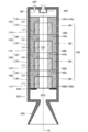
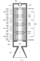
- FIG. 1 is a conceptual diagram illustrating a configuration of a hybrid rocket according to a first embodiment.
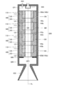
- FIG. 2 is a cross-sectional view illustrating a configuration of the solid fuel according to the first embodiment.
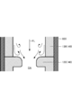
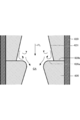
- FIG. 2 is a conceptual diagram showing a state after a solid fuel easily combustible portion according to the first embodiment has been burned off.
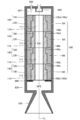
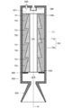
- FIG. 4 is a cross-sectional view illustrating a configuration of a solid fuel according to a second embodiment.
- FIG. 9 is a cross-sectional view illustrating a configuration of a solid fuel according to a third embodiment.
- FIG. 9 is a cross-sectional view illustrating a configuration of a solid fuel according to a fourth embodiment.
- FIG. 1 is a conceptual diagram illustrating a configuration of a hybrid rocket according to a first embodiment.
- FIG. 2 is a cross-sectional view illustrating a configuration of the solid fuel according to the first embodiment.
- FIG. 2 is a conceptual diagram showing a state after a solid fuel easily
- FIG. 13 is a cross-sectional view illustrating a configuration of a solid fuel according to a fifth embodiment.
- Sectional drawing which shows the structure of the solid fuel which concerns on Embodiment 6.
- FIG. 16 is a conceptual diagram showing a state after the easily combustible portion of the solid fuel according to Embodiment 6 has been burned off.
- Sectional drawing which shows the structure of the solid fuel which concerns on Embodiment 7.
- the conceptual diagram which shows the pressurization stop state of the cryogenic liquid supply apparatus which concerns on Embodiment 8.
- FIG. 18 is a conceptual diagram showing a state in which pressurization is stopped in the cryogenic liquid supply device according to the ninth embodiment.
- FIG. 19 is a conceptual diagram showing a pressurized state of the cryogenic liquid supply device according to the ninth embodiment.
- FIG. 4 is a conceptual diagram showing a state in which pressurization of a cryogenic liquid supply device according to a comparative embodiment is stopped.
- a hybrid rocket 800 As shown in FIG. 1, a hybrid rocket 800 according to the present embodiment includes a solid fuel 100 that generates thrust by being burned.
- the solid fuel 100 extends in a direction parallel to the direction in which the hybrid rocket 800 is propelled (hereinafter, referred to as a length direction).
- Openings AP are formed at both ends in the length direction of the solid fuel 100.
- the solid fuel 100 defines therein a flow path CA that communicates the opening AP of the starting end face 100a, which is one end face in the length direction, with the opening AP of the end face 100b, which is the other end face.
- the solid fuel 100 is formed in the shape of a hollow cylinder centered on a virtual straight line VL extending in the length direction.
- the inner surface of the channel CA extends from the opening AP of the start end surface 100a to the opening AP of the end surface 100b, and forms a side surface of a cylinder having the virtual straight line VL as a central axis.
- the hybrid rocket 800 also includes a liquid oxidant supply device 810 that supplies a liquid oxidant to the solid fuel 100.
- the liquid oxidant supply device 810 includes a tank 811 in which the liquid oxidant is stored, and a pressurizing gas source that supplies an inert gas for pushing the liquid oxidant in the tank 811 toward the solid fuel 100 to the tank 811. 812.
- the liquid oxidant supply device 810 includes a gas valve 813 provided in a flow path of an inert gas from the pressurized gas source 812 to the tank 811, and a liquid oxidant flow path from the tank 811 to the solid fuel 100. And a liquid valve 814 provided for the liquid crystal display.
- the hybrid rocket 800 also has a casing 820 that contains the solid fuel 100 and a nozzle 830 connected to an end of the casing 820. Nozzle 830 is located at the tail of hybrid rocket 800.
- the casing 820 is made of a metal material, specifically, stainless steel.
- the casing 820 is formed in a hollow cylindrical shape with the virtual straight line VL as a central axis, and covers the outer peripheral surface of the solid fuel 100.
- the solid fuel 100 is burned in a state housed in the casing 820.
- a gap GP1 as a front combustion chamber is secured between the inner wall of the end of the casing 820 opposite to the nozzle 830 in the length direction parallel to the virtual straight line VL and the start end face 100a of the solid fuel 100. Have been.
- the gap GP1 communicates with the flow path CA.
- the above-mentioned tank 811 communicates with the gap GP1 via the liquid valve 814.
- the hybrid rocket 800 also has an atomizer 840 arranged in the gap GP1, and an igniter 850 arranged to face the gap GP1.
- the sprayer 840 atomizes the liquid oxidant supplied from the tank 811.
- the atomized liquid oxidant flows into the flow path CA from the opening AP of the starting end face 100a of the solid fuel 100. That is, the liquid oxidant supply device 810 supplies the liquid oxidant to the flow path CA of the solid fuel 100 through the atomizer 840.
- a gap GP2 is provided between the inner wall of the end of the casing 820 to which the nozzle 830 is connected and the end surface 100b of the solid fuel 100.
- the gap GP2 communicates with the flow path CA, and serves as a rear combustion chamber for bringing the combustion of the pyrolysis gas obtained by thermally decomposing the solid fuel 100 closer to complete combustion.
- the igniter 850 generates a high-temperature fuel gas.
- the fuel gas generated by the igniter 850 flows into the flow path CA, and the solid fuel 100 is partially thermally decomposed.
- the fuel gas is burned by the atomized liquid oxidant reaching the vicinity of the inner wall surface of the flow path CA, and thereby the pyrolysis gas in which the inner surface of the solid fuel 100 facing the flow path CA is pyrolyzed and A flame is generated.
- the pyrolysis gas and the flame flow in the flow path CA in a direction from the start end face 100a to the end face 100b.
- a combustion gas is generated by burning the pyrolysis gas by the flame, and the heat of the combustion gas causes the surface layer of the unburned solid fuel 100 to thermally decompose to generate a pyrolysis gas.
- the cracked gas burns.
- the solid fuel 100 is burned in such a manner that the flow of the combustion gas in the direction from the start end face 100a toward the end face 100b occurs in the flow path CA.
- the fluid containing the combustion gas, the pyrolysis gas, and the flame flowing out from the opening AP of the terminal surface 100b is stirred in the gap GP2 as the rear combustion chamber.
- the combustion of the pyrolysis gas is brought close to complete combustion.
- the combustion gas and the flame generated by being stirred in the gap GP2 are accelerated by the nozzle 830 to a supersonic speed and injected.
- the reaction to the injection causes the hybrid rocket 800 to gain thrust and propell.
- the hybrid rocket 800 according to the present embodiment is characterized by the configuration of the solid fuel 100. Therefore, the configuration of the solid fuel 100 will be described in detail below with reference to FIG.
- the solid fuel 100 is divided into four blocks BK in a length direction parallel to the virtual straight line VL.
- Each block BK is formed in the shape of a hollow cylinder centering on the virtual straight line VL.
- the four blocks BK have the same configuration as each other.
- the configuration of each block BK will be described.
- Each block BK is composed of an easy-to-burn portion 110 made of a material that is relatively easy to burn, and a hard-to-burn portion 140 made of a material that is harder to burn than the easy-to-burn portion 110.
- combustion is more difficult than the easily combustible portion 110 means that the hybrid rocket 800 can burn intensely enough to give a propulsive thrust to the hybrid rocket 800, but is burned under the same conditions as the material constituting the easy combustible portion 110. In this case, it means that the speed at which the volume is reduced by combustion is lower than that of the material forming the easily combustible portion 110.
- the easily combustible portion 110 is made of paraffin
- the hardly combustible portion 140 is made of an acrylic resin.
- the easy-to-burn portion 110 is formed in the shape of a hollow cylinder centered on the virtual straight line VL.
- An inner peripheral surface as an inner surface surrounding the virtual straight line VL of the easy-to-burn portion 110 constitutes an easy-to-burn exposed surface 111 exposed to the flow path CA.
- the length of the easy burning portion 110 in the direction parallel to the virtual straight line VL is shorter than the length of the block BK in the direction parallel to the virtual straight line VL.
- the length of the non-combustible portion 140 in the direction parallel to the virtual straight line VL is equal to the length of the block BK in the direction parallel to the virtual straight line VL.
- the hard-to-burn portion 140 is joined to the easy-to-burn portion 110 to form a hollow cylindrical block BK together with the easy-to-burn portion 110.
- the shape of the difficult-to-burn portion 140 will be specifically described.
- Both ends of the flame retardant portion 140 in the length direction parallel to the virtual straight line VL are open.
- the area of the opening of the first end surface 140a, which is one end surface in the length direction parallel to the virtual straight line VL, of the difficult-to-burn portion 140 is smaller than the area of the opening of the second end surface 140b, which is the other end surface.
- the first end face 140a is arranged closer to the start end face 100a in the length direction parallel to the virtual straight line VL, and the second end face 140b is arranged closer to the end face 100b.
- the hard-to-burn portion 140 has a thick portion 120 forming the first end surface 140a and a second end surface 140b, and has a diameter that is more perpendicular to the virtual straight line VL than the thick portion 120 is. And a thin portion 130 having a small thickness in the direction.
- the thin portion 130 covers an outer peripheral surface of the easy-combustion portion 110 as an outer surface opposite to the easy-combustion exposure surface 111 in a radial direction orthogonal to the virtual straight line VL.
- the thick portion 120 has a hardly combustible exposed surface 121 that is exposed to the flow path CA continuously with the first end surface 140a.
- the hard-burning exposed surface 121 is adjacent to the easy-burning exposed surface 111 of the easy-burning portion 110.
- the hard-burning exposed surface 121 forms the inner peripheral surface of a cylinder having the virtual straight line VL as a central axis, together with the easily-burning exposed surface 111.
- the end face closer to the start end face 100a is constituted by the first end face 140a of the thick portion 120, and the end face closer to the end face 100b. Is constituted by a second end surface 140b of the thin portion 130 and an end surface of the easy-to-burn portion 110 closer to the terminal end surface 100b.
- the first end face 140a of the thick portion 120 in the block (hereinafter referred to as the end block) BK closer to the end face 100b is the start end.
- the block closer to the surface 100a (hereinafter, referred to as a starting end block) BK is in contact with the end surface of the easy-to-burn portion 110 closer to the end surface 100b.
- the portion constituting the first end surface 140a of the difficult-to-burn portion 140 in the end-side block BK, specifically, the thick portion 120 is the starting end surface 100a of the easy-to-burn portion 110 in the start-side block BK.
- the starting end side block BK in the direction from the end surface 100b to the end surface 100b.
- the hybrid rocket 800 includes a stopper 860 in the gap GP2 as the rear combustion chamber.
- the stopper 860 is made of a heat-resistant material, specifically, bakelite.
- the stopper 860 is fixed at a position facing the thin portion 130 and the easy-to-burn portion 110, which constitute the end face closer to the nozzle 830, of the last block BK. For this reason, the stopper 860 prevents the easy-to-burn portion 110 in the last block BK from separating from the hard-to-burn portion 140 in the last block BK toward the nozzle 830.
- the block BK described above can be obtained through a first step of forming the difficult-to-burn part 140 and a second step of pouring the material of the easy-to-burn part 110 into the formed difficult-to-burn part 140.
- a work material made of an acrylic resin is prepared, and the difficult-to-burn portion 140 is created by processing the work material.
- paraffin which is the material of the easy-to-burn portion 110, is fluidized by heating and poured into the hard-to-burn portion 140.
- the paraffin is solidified, a block BK in which the easily combustible portion 110 and the difficult combustible portion 140 are joined is obtained.
- the difficult-to-burn portion 140 may be formed by casting similarly to the easy-to-burn portion 110.
- a mold that defines the space into which the material of the easy-to-burn portion 110 is poured together with the hard-to-burn portion 140 may be used.
- the casing is The problem that 820 is exposed to the flow path CA can be avoided.
- the inner surface of the thin portion 130 of the difficult-to-burn portion 140 that covers the outer peripheral surface of the easy-to-burn portion 110 is exposed to the flow path CA after the easy-to-burn portion 110 disappears.
- the inner surface of the thin portion 130 protects the casing 820 while burning more slowly than the easy-to-burn portion 110. Therefore, the casing 820 is hardly damaged.
- the thick portion 120 of the difficult-to-burn portion 140 in the end block BK plays the role of a stopper that contacts the entire area of the end surface closer to the end surface 100b of the easy-to-burn portion 110 in the start block BK. Therefore, in the process of combustion, the easily combustible portion 110 is less likely to be separated from the difficult combustible portion 140.
- the easily combustible exposed surface 111 and the hardly combustible exposed surface 121 constitute one continuous curved surface.
- the inner surface of the flow path CA forms a side surface of a cylinder having the virtual straight line VL as a central axis. Therefore, as compared with the case where the inner surface of the flow path CA has irregularities, the combustion gas flows more smoothly in the flow path CA in the initial stage after the start of combustion. This contributes to improving the thrust applied to the hybrid rocket 800.
- the easy-to-burn portion 110 that is relatively easy to burn is arranged at a position facing the flow path CA. For this reason, a large thrust is obtained in the initial stage after the start of combustion, as compared with the case where only the difficult combustion portion 140 faces the flow path CA.
- the sum of the areas of all the easy-burning exposed surfaces 111 is larger than the sum of the areas of all the hard-burning exposed surfaces 121. For this reason, the combustion gas flows through the flow path CA where a large amount of the easily combustible exposed surface 111 is exposed, and a large thrust is easily obtained in an initial stage after the start of combustion.
- the thick portion 120 which has served as a stopper portion in the hardly combustible portion 140, projects into the flow path CA. Therefore, the thick portion 120 disturbs the flow of the fluid FL including the liquid oxidizer, the pyrolysis gas thermally decomposed by the hard-to-burn portion 140, the combustion gas burned by the pyrolysis gas, and the flame.
- the four members are agitated, so that the thermal decomposition of the difficult-to-burn portion 140 is promoted.
- the promotion of the thermal decomposition of the difficult-to-burn portion 140 contributes to the improvement of the thrust given to the hybrid rocket 800.
- the thick-walled portion 120 not only serves as a stopper for preventing the easily combustible portion 110 from peeling off, but also in the stage after the easy combustible portion 110 is burned out. , Also serves to promote the combustion of the difficult-to-burn portion 140 itself.
- the thick portion 120 is arranged at a position closer to the start end face 100a than the thin portion 130, but conversely, the thin portion 130 is closer to the start end face 100a than the thick portion 120. May be arranged at a position close to.
- specific examples thereof will be described.
- the first end surface 140a having the opening with the smaller area in the hard-to-burn portion 140 of each block BK is closer to the end surface 100b.
- the second end surface 140b that is arranged and has an opening with a larger area is arranged closer to the start end surface 100a.
- the thick portion 120 constituting the first end surface 140a of the difficult-to-burn portion 140 constitutes a stopper portion for the easy-to-burn portion 110 of the block BK having the difficult-to-burn portion 140. I do. Other configurations and effects are the same as those in the first embodiment.
- the thick portion 120 of the difficult-to-burn portion 140 of each block BK covers the outer peripheral surface of the easy-to-burn portion 110, similarly to the thin portion 130. ing.
- the thrust at the initial stage after the start of combustion is larger than that of the first embodiment. Can be obtained.
- the thick portion 120 of the difficult-to-burn portion 140 in the end block BK is in contact with a part of the end surface of the easy-to-burn portion 110 in the start block BK which is closer to the end surface 100b. . Therefore, similarly to the case of the first embodiment, the thick portion 120 plays a role of a stopper portion for the easy-to-burn portion 110 of the start end block BK.
- Other configurations and effects are the same as those in the first embodiment.
- Embodiment 4 In the above-described Embodiment 1-3, in each of the blocks BK, the configuration in which the hard-to-burn portion 140 includes only one thick portion 120 is exemplified. However, the hard-to-burn portion 140 may include a plurality of thick portions 120. . Hereinafter, specific examples thereof will be described.
- the solid fuel 400 according to the present embodiment is also divided into four blocks BK, as in the case of the first embodiment.
- Each block BK includes an easy-to-burn portion 410 and a hard-to-burn portion 450.
- the difficult-to-burn portion 450 has a shape that covers both end surfaces of the easy-to-burn portion 410 in the length direction parallel to the virtual straight line VL and the outer peripheral surface as the outer surface. A portion of the both ends of the easy-to-burn portion 410 that is closer to the terminal surface 100b of the hard-to-burn portion 450 constitutes a stopper for the easy-to-burn portion 410.
- a specific description will be given.
- the hard-to-burn portion 450 has a first thick portion 420 and a second thick portion 430, and the first thick portion 420 and the second thick portion 430 are more orthogonal to the length direction than the first thick portion 420 and the second thick portion 430. And a thin portion 440 having a small radial thickness.
- the first thick portion 420 constitutes a first end surface 450a which is one end surface in the length direction of the difficult-to-burn portion 450, and is exposed to the flow path CA continuously with the first end surface 450a. It has one hard-burning exposed surface 421.
- the second thick portion 430 forms a second end surface 450b which is the other end surface in the length direction of the difficult-to-burn portion 450, and is exposed to the flow path CA continuously with the second end surface 450b. It has two flame-exposed surfaces 431.
- the easy-to-burn portion 410 is disposed between the first thick portion 420 and the second thick portion 430. Both end surfaces of the easy-to-burn portion 410 are covered by the first thick portion 420 and the second thick portion 430.
- the thin portion 440 connects the first thick portion 420 and the second thick portion 430 while covering the outer peripheral surface as the outer surface of the easy-to-burn portion 410.
- the first thick part 420 is arranged closer to the start end face 100a, and the second thick part 430 is arranged closer to the end face 100b. That is, the first thick portion 420 covers the end surface of the easy-to-burn portion 410 closer to the start end surface 100a, and the second thick portion 430 is the closer to the end surface 100b of the easy-to-burn portion 410. It covers the end face.
- the second thick portion 430 constitutes a stopper portion for the easy-to-burn portion 410.
- Other configurations and effects are the same as those in the first embodiment.
- the solid fuel 100 is divided into a plurality of blocks BK, but the solid fuel 100 does not necessarily have to be divided into a plurality of blocks BK.
- specific examples thereof will be described.
- the solid fuel 500 is configured such that an integral easy-to-burn portion 510 and an integral hard-to-burn portion 520 are joined.
- Each of the easy-to-burn portion 510 and the hard-to-burn portion 520 is formed in a tubular shape, and extends from the start end face 100a to the end face 100b.
- the easy-to-burn portion 510 is arranged closer to the virtual straight line VL than the hard-to-burn portion 520 in the radial direction orthogonal to the virtual straight line VL.
- the inner surface of the flow path CA in the initial state before the solid fuel 500 is burned is constituted by the easily burned exposed surface 511 of the easily burnable portion 510 over the entire area.
- the hard-to-burn portion 520 includes a thin portion 521 having a relatively thin radial thickness perpendicular to the virtual straight line VL and a thick portion 522 having a relatively thick radial thickness parallel to the virtual straight line VL. It has a configuration in which a plurality are alternately arranged in the length direction.
- the thick portion 522 bites into the easy-to-burn portion 510 in a state protruding radially inward closer to the flow path CA than the thin portion 521, and cuts into the easy-to-burn portion 510 in the direction from the start end face 100a to the end face 100b. Plays the role of a stopper for preventing peeling of the sheet.
- the thick portion 522 of the hard-to-burn portion 140 of the first embodiment after the burnable portion 510 of the easy-to-burn portion 520 is removed. It also serves to promote combustion.
- the thickness in the radial direction orthogonal to the virtual straight line VL changes stepwise between the first end face 140a and the second end face 140b as the difficult-to-burn portion 140 constituting each block BK.
- the thickness of the difficult-to-burn portion 140 may change continuously from the first end surface 140a toward the second end surface 140b.
- the solid fuel 600 according to the present embodiment is also divided into four blocks BK, as in the case of the first embodiment.
- Each block BK includes an easy-to-burn portion 610 and a hard-to-burn portion 620.
- the area of the opening of the first end surface 620a which is one end surface of the difficult-to-burn portion 620 in the length direction parallel to the virtual straight line VL, is smaller than the area of the opening of the second end surface 620b, which is the other end surface.
- the first end face 620a is arranged closer to the start end face 100a, and the second end face 620b is arranged closer to the end face 100b.
- the easy-combustion exposed surface 611 of the easy-combustion portion 610 is exposed to the flow path CA from the position of the first end surface 620a to the position of the second end surface 620b in the length direction parallel to the virtual straight line VL. That is, the inner surface of the flow path CA in the initial state is constituted by the easily combustible exposed surface 611 over the entire area.
- the hard-to-burn portion 620 sets the outer peripheral surface of the easy-to-burn portion 610 as the outer surface opposite to the easy-to-burn exposed surface 611 in the radial direction orthogonal to the virtual straight line VL from the position of the first end surface 620a to the second end surface. 620b.
- An inner peripheral surface 621 of the hard-to-burn portion 620 in each block BK as an inner surface remote from the casing 820 in a radial direction orthogonal to the virtual straight line VL is formed on the second end surface 620b in a length direction parallel to the virtual straight line VL. As it approaches, it is inclined so as to gradually approach the casing 820. That is, in each block BK, the radial thickness of the difficult-to-burn portion 620 continuously decreases from the first end surface 620a to the second end surface 620b.
- the inner peripheral surface 621 of the hard-to-burn portion 620 is an example of an inner surface that is exposed to the flow path CA after the easy-to-burn portion 110 has disappeared.
- the inner peripheral surface 621 protects the casing 820 while burning more slowly than the easy-to-burn portion 110 after the easy-to-burn portion 110 has disappeared.
- the first end face 620a of the difficult-to-burn part 620 in the end block BK is in contact with the end face of the easy-to-burn part 610 in the start block BK which is closer to the end face 100b. For this reason, the part which constitutes the 1st end face 620a of the difficult-to-burn part 620 in the terminal side block BK constitutes the stopper part for the easy-to-burn part 610 of the start side block BK. Therefore, the easily combustible portion 610 is less likely to be separated from the difficult combustible portion 620 during the combustion process.
- the inner peripheral surface 621 of the hardly combustible portion 620 changes the cross-sectional area of the flow path CA perpendicular to the virtual straight line VL as it approaches the second end surface 620b. It constitutes the Suehiro part which is gradually increasing. And the part which comprises the 1st end surface 620a in the difficult combustion part 620 will be in the state which protruded in the flow path CA.
- the first end surface 620a is composed of a liquid oxidizer, a pyrolysis gas obtained by thermally decomposing the hardly combustible portion 620, a combustion gas obtained by burning the pyrolysis gas, and a fluid containing a flame. Disturb FL flow.
- the thermal decomposition of the difficult-to-burn portion 620 is promoted by stirring the four members.
- the promotion of the thermal decomposition of the difficult-to-burn portion 620 contributes to the improvement of the thrust given to the hybrid rocket 800.
- the portion constituting the first end face 620a in the difficult-to-burn portion 620 not only plays a role of a stopper portion for preventing the easy-to-burn portion 610 from peeling off at an early stage after the start of combustion, but also serves as a stopper portion. At the stage after burning of the easy-to-burn portion 610, it also serves to promote the combustion of the hard-to-burn portion 620 itself.
- the portion constituting the first end surface 620a of the difficult-to-burn portion 620 is less likely to be completely burned out than the thick portion 120 shown in FIG. For this reason, the effect of promoting the combustion of the difficult-to-burn portion 620 itself is likely to be maintained.
- the inner peripheral surface 621 of the difficult-to-burn portion 620 constitutes a divergent portion that gradually increases the cross-sectional area of the flow path CA, so that the flow velocity of the fluid FL is moderately reduced until it hits the first end surface 620a. This is considered to be due to the fact that local excessive wear of the portion constituting the first end surface 620a is suppressed.
- the inner peripheral surface 621 of the hard-to-burn portion 620 becomes a virtual straight line VL.
- the fact that it is difficult to form a parallel flat surface is also considered to be one of the reasons that the portion constituting the first end surface 620a is likely to remain.
- the solid fuel 600 is divided into a plurality of blocks BK, but the solid fuel 600 does not necessarily have to be divided into a plurality of blocks BK.
- specific examples thereof will be described.
- the solid fuel 700 is configured by joining an integral easy-to-burn portion 710 and an integral difficult-to-burn portion 720.
- Each of the easy-to-burn portion 710 and the hard-to-burn portion 720 extends from the start end face 100a to the end face 100b.
- the difficult-to-burn portion 720 has a stepped portion 721 protruding in a direction away from the casing 820 in a radial direction orthogonal to the virtual straight line VL, and gradually approaches the casing 820 from the stepped portion 721 as it approaches the terminal surface 100b. And a divergent portion 722 that is inclined.
- the difficult-to-burn portion 720 has a plurality of sets of the step portion 721 and the divergent portion 722 in the length direction, specifically, four sets.
- the step portion 721 of the uppermost block BK facing the gap GP1 constitutes the start end face 100a.
- the easily combustible portion 710 exists radially inward of each stepped portion 721 of the hardly combustible portion 720 with a thickness.
- the inner surface of the flow path CA in the initial state before the solid fuel 700 burns is constituted by the easy-combustion exposed surface 711 of the easy-combustion portion 710 over the entire area.
- step portions 721 of the four step portions 721, three step portions 721 excluding the portion constituting the start end face 100a bite into the easy-to-burn portion 710, and a stopper for preventing the easy-to-burn portion 710 from peeling off. Plays the role of department.
- the step portions 721 are difficult to burn at the stage after the easy-to-burn portion 710 is burned out. It also serves to promote the combustion of the combustion section 720 itself.
- paraffin is used as the material of the easy-to-burn portion 110 and acrylic resin is used as the material of the hard-to-burn portion 140.
- the material of the part 110 and the difficult-to-burn part 140 is not particularly limited.
- a polyethylene resin or an ABS resin can be used as the material of the difficult combustible portion 140. The same applies to other embodiments.
- the solid fuel 100 includes the easy-to-burn portion 110 and the hard-to-burn portion 140 has been described, but the solid fuel 100 has a portion other than the easy-to-burn portion 110 and the hard-to-burn portion 140. May be.
- the solid fuel 100 may include a third material that is difficult to combust with the easily combustible portion 110 and the hardly combustible portion 140. The same applies to other embodiments.
- the configuration in which the solid fuel 100 is applied to the hybrid rocket 800 is illustrated.
- the solid fuel 100 can be applied to a rocket other than the hybrid rocket 800 such as a solid fuel rocket.
- blocks BK having different shapes may be combined.
- the block BK shown in FIG. 1 and the block BK shown in FIG. 8 may be combined.
- Embodiment 1-7 the case where the inner surface of the flow path CA constitutes the side surface of a cylinder having the virtual straight line VL as the central axis has been described, but the inner surface of the flow path CA has the virtual axis VL as the central axis. It is also possible to form a column other than a cylinder, for example, a side surface of a prism.
- the thick portion 522 serving as the stopper portion extends over the entire circumference in the circumferential direction around the virtual straight line VL.
- the step portion 721 illustrated in FIG. Even when the difficult-to-burn portion 520 has a rod-shaped protrusion inward in the radial direction approaching the virtual center axis VL, the protrusion cuts into the easy-to-burn portion 510, so that the protrusion is a stopper portion. Can play a role.
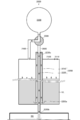
- cryogenic liquid supply device that can be used as a specific example of the liquid oxidant supply device 810 illustrated in FIG. 1 will be described.
- the cryogenic liquid supply device 3000 includes a liquid-tight and air-tight tank 3100 in which the cryogenic liquid UL is stored. On the upper surface of the tank 3100, an injection port 3110 for injecting the cryogenic liquid UL into the inside is formed.
- the inlet 3110 is air-tightly and liquid-tightly closed after the injection of the cryogenic liquid UL is completed.
- the cryogenic liquid supply device 3000 includes a supply pipe 3200 that guides the cryogenic liquid UL inside the tank 3100 to a supply destination SD disposed below the tank 3100.
- the supply pipe 3200 has a double pipe structure including an outer pipe 3210 and an inner pipe 3220 passing through the outer pipe 3210.
- the outer tube 3210 extends downward from the upper surface inside the tank 3100 toward the bottom surface inside the tank.
- the upper end of the inner pipe 3220 is open at a position facing the upper surface of the tank 3100.
- the lower end of the inner pipe 3220 is connected to the supply destination SD.
- the cryogenic liquid supply device 3000 includes a gas outlet / inlet pipe 3400 having one end communicating with the inside of the tank 3100, a three-way valve 3500 connected to the other end of the gas outlet / inlet pipe 3400, and a three-way valve 3500 having one end. And a gas guide tube 3600 having the other end communicating with the inside of the tank 3100.
- One end of the gas inlet / outlet pipe 3400 communicates with a region inside the tank 3100 and outside the outer pipe 3210.
- the other end of the gas guide tube 3600 communicates with a region inside the outer tube 3210 inside the tank 3100.
- the cryogenic liquid supply device 3000 also includes a pressurizing gas source 3300 that supplies a pressurizing gas for extruding the cryogenic liquid UL inside the tank 3100 through the supply pipe 3200 to the supply destination SD.
- the pressurizing gas source 3300 is also connected to the three-way valve 3500.
- the supply of the pressurizing gas from the pressurizing gas source 3300 is cut off and the three-way valve 3500 is set to a pressurization stopped state in which the gas outlet / inlet pipe 3400 and the gas guide pipe 3600 communicate with each other.
- the cryogenic liquid UL is injected into the tank 3100 via the injection port 3110.
- the air inside the tank 3100 is pushed out to the supply destination SD through the gas inlet / outlet pipe 3400, the gas guide pipe 3600, and the inner pipe 3220.
- the outside of the outer tube 3210 and the inside of the outer tube 3210 are communicated with each other by the gas lead-in / out tube 3400 and the gas guide tube 3600.
- the liquid surface height of the cryogenic liquid UL is equal to the inside of the outer tube 3210.
- the three-way valve 3500 is switched to a pressurized state in which one end of the gas guide pipe 3600 is closed and the pressurized gas source 3300 and the gas outlet / inlet pipe 3400 communicate with each other. Then, the liquid surface of the cryogenic liquid UL outside the outer tube 3210 is pressurized by the pressurizing gas supplied from the pressurizing gas source 3300 to the inside of the tank 3100 through the gas outlet / inlet pipe 3400.
- the liquid level of the cryogenic liquid UL outside the outer tube 3210 drops, the liquid level of the cryogenic liquid UL inside the outer tube 3210 rises, and the cryogenic liquid UL flows into the inner tube 3220.
- the cryogenic liquid UL that has flowed in is supplied to the supply destination SD through the inner pipe 3220.
- cryogenic liquid supply device 3000 when the cryogenic liquid UL is injected into the tank 3100 in the pressurization stop state, the liquid level of the cryogenic liquid UL rises from the bottom of the tank 3100 to the upper end of the inner pipe 3220. Great care must be taken not to exceed the limit height H, which represents the distance to the opening of.
- the cryogenic liquid UL flows into the inner pipe 3220 and flows out to the supply destination SD through the inner pipe 3220 even though the pressurizing gas is not supplied. This is because an overflow occurs.
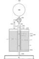
- the cryogenic liquid supply device 1000 includes a liquid-tight and air-tight tank 1100 in which the cryogenic liquid UL is stored.
- An injection port 1110 for injecting the cryogenic liquid UL into the inside is formed on the upper surface of the tank 1100.
- the inlet 1110 is air-tightly and liquid-tightly closed after the injection of the cryogenic liquid UL into the tank 1100 is completed.
- the cryogenic liquid supply device 1000 includes a supply pipe 1200 for guiding the cryogenic liquid UL inside the tank 1100 to a supply destination SD arranged below the tank 1100, and a cryogenic liquid inside the tank 1100.
- a pressurizing gas source 1300 that supplies a pressurizing gas for pushing the UL to the supply destination SD through the supply pipe 1200 is provided.
- the supply pipe 1200 has an inflow end 1200a into which the cryogenic liquid UL flows, and an outflow end 1200b from which the cryogenic liquid UL flows, and the cryogenic liquid UL extends from the inflow end 1200a to the outflow end 1200b. It constitutes a flowing pipeline.
- the inflow end 1200a is immersed in the cryogenic liquid UL inside the tank 1100.
- the outflow end 1200b is connected to the supply destination SD.
- the supply pipe 1200 according to the present embodiment is folded back as an upward protruding part that protrudes upward from the tank 1100 between the inflow end 1200a and the outflow end 1200b along the conduit through which the cryogenic liquid UL flows.
- the point having the portion 1220 is the most significant feature.
- the supply pipe 1200 has, in addition to the folded portion 1220, an upper guide portion 1210 extending from the inflow end portion 1200a to the folded portion 1220, and a lower guide portion 1230 extending from the folded portion 1220 to the supply destination SD. It is formed in an inverted U shape as a whole.
- One end of the upper guide portion 1210 forms an inflow end 1200a.
- the other end of the upper guide portion 1210 is connected to the folded portion 1220.
- the upper guide portion 1210 guides the cryogenic liquid UL upward from the inflow end portion 1200a toward the folded portion 1220.
- the turn-back portion 1220 turns the cryogenic liquid UL guided upward by the upper guide portion 1210 downward toward the inside of the tank 1100. As described above, the folded portion 1220 forms a part of a conduit through which the cryogenic liquid UL flows.
- One end of the lower guide portion 1230 is connected to the folded portion 1220.
- the lower guide 1230 penetrates the bottom surface of the tank 1100, and the other end of the lower guide 1230 forms an outflow end 1200b.
- the lower guide portion 1230 guides the cryogenic liquid UL turned downward at the turn-back portion 1220 toward the supply destination SD via the inside of the tank 1100.
- the cryogenic liquid supply device 1000 includes a gas outlet / inlet pipe 1400 having one end communicating with the inside of the tank 1100, a three-way valve 1500 serving as a gas valve connected to the other end of the gas outlet / inlet pipe 1400, and an end having three ends.
- a gas guide tube 1600 connected to the one-way valve 1500.
- the other end of the gas guide pipe 1600 is connected to a portion of the lower guide 1230 of the supply pipe 1200 between the bottom surface of the tank 1100 and the supply destination SD.
- the three-way valve 1500 is also connected to a pressurizing gas source 1300.
- the three-way valve 1500 is in a state in which the supply of the pressurizing gas from the pressurizing gas source 1300 to the tank 1100 is cut off and the pressurization stop state in which the gas outlet / inlet pipe 1400 communicates with the gas guide pipe 1600; It is possible to switch between a pressurized state where the communication with the gas guide tube 1600 is cut off and the pressurized gas source 1300 and the gas lead-in / out tube 1400 are in communication.
- FIG. 11 shows the cryogenic liquid supply device 1000 in a state where the pressurization is stopped.
- the user injects the cryogenic liquid UL into the tank 1100 from the inlet 1110.
- the air inside the tank 1100 is pushed out by the injected cryogenic liquid UL to the supply destination SD through the gas inlet / outlet pipe 1400, the gas guide pipe 1600, and the lower guide part 1230. .
- an air discharge hole may be formed in the tank 1100, or a part of the inlet 1110 may serve as an air discharge hole.
- the inside of the tank 1100 and the inside of the supply pipe 1200 communicate with each other through the gas outlet / inlet pipe 1400 and the gas guide pipe 1600, the pressure inside the tank 1100 and the inside of the supply pipe 1200 are equal. Therefore, the liquid level of the cryogenic liquid UL inside the tank 1100 and the liquid level of the cryogenic liquid UL in the upper guide 1210 are equal.
- the pressure of the supply destination SD is equal to the atmospheric pressure, and in the pressurization stop state, the inside of the tank 1100 and the inside of the supply pipe 1200 are kept at the atmospheric pressure.
- the folded portion 1220 projects upward from the tank 1100, when the cryogenic liquid UL is injected into the tank 1100, at least from the folded portion 1220 to the outflow end 1200b in the pipeline constituted by the supply pipe 1200.
- the gap VP is secured between the two.
- the cryogenic liquid UL when the cryogenic liquid UL is injected into the tank 1100, it is possible to avoid an overflow problem in which the cryogenic liquid UL flows out to the supply destination SD through the supply pipe 1200. Therefore, the operation of injecting the cryogenic liquid UL into the tank 1100 can be easily performed.
- the liquid level of the cryogenic liquid UL inside the tank 1100 can be set higher than in the past, the problem of overflow can be avoided.
- the liquid level of the cryogenic liquid UL inside the tank 1100 can be set higher than the limit height H shown in FIG. Therefore, the filling rate of the cryogenic liquid UL into the tank 1100 can be increased as compared with the related art.
- the injection port 1110 is air-tightly and liquid-tightly closed.
- the gas in which the cryogenic liquid UL has vaporized inside the tank 1100 is discharged to the outside of the tank 1100 through the gas inlet / outlet pipe 1400. That is, the gas lead-in / out pipe 1400 plays a role of a gas discharge unit that discharges the gas in which the cryogenic liquid UL is vaporized inside the tank 1100 to the outside of the tank 1100.
- the gas discharged from the gas outlet / inlet pipe 1400 is guided to the supply destination SD through the gas guide pipe 1600. Specifically, the gas discharged from the gas outlet / inlet pipe 1400 is supplied to the supply destination SD through the gas guide pipe 1600 and the gap VP in the lower guide portion 1230 of the supply pipe 1200. Therefore, in the pressure stop state, the pressure increase of the tank 1100 is suppressed.
- the three-way valve 1500 is switched to the pressurized state.
- the operation of the cryogenic liquid supply device 1000 in the pressurized state will be described.
- the pressurizing gas is supplied from the pressurizing gas source 1300 to the tank 1100 through the gas outlet / inlet pipe 1400.
- the gas outlet / inlet pipe 1400 also serves to guide the pressurizing gas to the tank 1100.
- the liquid level of the cryogenic liquid UL inside the tank 1100 is pressurized downward by the pressurizing gas. Accordingly, the cryogenic liquid UL flows into the upper guide 1210 from the inflow end 1200a.
- the cryogenic liquid UL that has flowed into the upper guide portion 1210 rises toward the folded portion 1220, is folded at the folded portion 1220, and descends toward the supply destination SD via the outflow end portion 1200b. In this manner, the cryogenic liquid UL is pushed out from the inflow end 1200a to the supply destination SD through the outflow end 1200b by the pressurizing gas.
- the lower guide 1230 passes through the inside of the tank 1100, and the cryogenic liquid UL that has been folded downward at the folded portion 1220 is supplied to the supply destination SD via the interior of the tank 1100. For this reason, the cryogenic liquid UL flowing through the lower guide portion 1230 is less likely to be heated by the outside air than when the lower guide portion 1230 is arranged outside the tank 1100.
- the inverted U-shaped supply pipe 1200 is used.
- the supply pipe 1200 guides the cryogenic liquid UL once above the tank 1100 and turns it downward above the tank 1100. If so, the shape is not particularly limited. Hereinafter, a specific example in which the shape of the supply pipe 1200 is modified will be described.
- the cryogenic liquid supply device 2000 includes a liquid-tight and air-tight tank 2100 in which the cryogenic liquid UL is stored, and a cryogenic liquid UL in the tank 2100.
- a supply pipe 2200 that guides to a supply destination SD disposed below the storage tank 2100, and a pressurizing gas that supplies a pressurizing gas for extruding the cryogenic liquid UL inside the tank 2100 to the supply destination SD through the supply pipe 2200.
- a pressure gas source 2300 a pressure gas source 2300.
- the supply pipe 2200 has an inflow end 2200a into which the cryogenic liquid UL flows, and an outflow end 2200b from which the cryogenic liquid UL flows, and the cryogenic liquid UL extends from the inflow end 2200a to the outflow end 2200b. It constitutes a flowing pipeline.
- the inflow end 2200a is immersed in the cryogenic liquid UL inside the tank 2100.
- the outflow end 2200b is connected to the supply destination SD.
- the supply pipe 2200 has an upper protruding portion 2200c that protrudes upward from the tank 2100 between the inflow end portion 2200a and the outflow end portion 2200b along a conduit through which the cryogenic liquid UL flows.
- the point is the biggest feature.
- the supply pipe 2200 has a straight tubular outer pipe 2210 and a straight tubular inner pipe 2220 passing through the inside of the outer pipe 2210 and penetrating the tank 2100.
- One end of the outer tube 2210 constitutes the inflow end 2200a.
- the other end of the outer tube 2210 forms an upward protruding portion 2200c.
- One end of the inner tube 2220 is open inside the upper protruding portion 2200c.
- the other end of the inner tube 2220 forms an outflow end 2200b.
- the cryogenic liquid UL is guided upward from the inflow end 2200a toward the upward protruding portion 2200c by the inner surface of the outer tube 2210 and the outer surface of the inner tube 2220. Then, the cryogenic liquid UL flows into the opening at one end of the inner pipe 2220 at the upper protruding portion 2200c, and the cryogenic liquid UL that has flowed in is guided by the inner pipe 2220 to the supply destination SD.
- the cryogenic liquid supply device 2000 includes a gas outlet / inlet pipe 2400 having one end communicating with the inside of the tank 2100, a three-way valve 2500 as a gas valve connected to the other end of the gas outlet / inlet 2400, And a gas guide tube 2600 connected to the one-way valve 2500.
- One end of the gas outlet / inlet pipe 2400 communicates with a region outside the outer pipe 2210 inside the tank 2100.
- the other end of the gas guide tube 2600 communicates with a region inside the outer tube 2210 inside the tank 2100, specifically, with the inside of the upper protruding portion 2200c.
- the three-way valve 2500 is also connected to a pressurizing gas source 2300.
- the three-way valve 2500 is in a state where the supply of the pressurizing gas from the pressurizing gas source 2300 to the tank 2100 is cut off and the pressurization stop state in which the gas outlet / inlet pipe 2400 and the gas guide pipe 2600 communicate with each other. It is possible to switch between a pressurized state in which the communication with the gas guide pipe 2600 is cut off and the pressurized gas source 2300 and the gas outlet / inlet pipe 2400 are in communication.
- FIG. 13 shows the cryogenic liquid supply device 2000 in a state where the pressurization is stopped.
- the user injects the cryogenic liquid UL from the injection port 2110 into a region outside the outer tube 2210 inside the tank 2100.
- the air inside the tank 2100 is pushed out to the supply destination SD through the gas inlet / outlet pipe 2400, the gas guide pipe 2600, and the inner pipe 2220 by the injected cryogenic liquid UL.
- the inside and outside regions of the outer tube 2210 inside the tank 2100 communicate with each other through the gas outlet / inlet pipe 2400 and the gas guide tube 2600.
- the pressure inside and outside are equal. Therefore, the liquid level of the cryogenic liquid UL is equal between the inside and the outside of the outer tube 2210 inside the tank 2100.
- the pressure of the supply destination SD is equal to the atmospheric pressure, and inside the tank 2100, the inside and the outside of the outer tube 2210 are kept at the atmospheric pressure when the pressurization is stopped.
- the upper protruding portion 2200c protrudes upward from the tank 2100, when the cryogenic liquid UL is injected into the tank 2100, at least the upper protruding portion in the pipeline formed by the supply pipe 2200 through which the cryogenic liquid UL flows. A gap VP is secured between the portion 2200c and the outflow end 2200b.
- the cryogenic liquid UL when the cryogenic liquid UL is injected into the tank 2100, it is possible to avoid the problem of overflow in which the cryogenic liquid UL flows out to the supply destination SD through the inner pipe 2220. Therefore, the operation of injecting the cryogenic liquid UL into the tank 2100 can be easily performed.
- the liquid level of the cryogenic liquid UL inside the tank 2100 can be set higher than before, the problem of overflow can be avoided.
- the liquid level of the cryogenic liquid UL inside the tank 2100 can be set higher than the limit height H shown in FIG. Therefore, the filling rate of the cryogenic liquid UL into the tank 2100 can be increased as compared with the related art.
- the injection port 2110 is air-tightly and liquid-tightly closed.
- the gas in which the cryogenic liquid UL has vaporized inside the tank 2100 is discharged to the outside of the tank 2100 through the gas outlet / inlet pipe 2400. That is, the gas lead-in / out pipe 2400 plays a role of a gas discharge unit that discharges the gas in which the cryogenic liquid UL is vaporized inside the tank 2100 to the outside of the tank 2100.
- the gas discharged from the gas outlet / inlet pipe 2400 is guided to the supply destination SD through the gas guide pipe 2600, the upper protruding portion 2200c, and the gap VP in the inner pipe 2220. Therefore, in the pressure stop state, the pressure increase of the tank 2100 is suppressed.
- the three-way valve 2500 is switched to a pressurized state.
- the operation of the cryogenic liquid supply device 2000 in the pressurized state will be described.
- the pressurizing gas source 2300 and the gas outlet / inlet pipe 2400 communicate with each other, the pressurizing gas is supplied from the pressurizing gas source 2300 to the tank 2100 through the gas outlet / inlet pipe 2400.
- the gas outlet / inlet pipe 2400 also serves to guide the pressurizing gas to the tank 2100.
- the liquid level of the cryogenic liquid UL inside the tank 2100 is pressurized downward by the pressurizing gas.
- the cryogenic liquid UL flows between the outer pipe 2210 and the inner pipe 2220 from the inflow end 2200a.
- the inflowing cryogenic liquid UL rises toward the upper protruding portion 2200c, is folded back at the upper protruding portion 2200c, and descends through the inner pipe 2220 toward the supply destination SD.
- the cryogenic liquid UL is extruded from the inflow end 2200a to the supply destination SD through the outflow end 2200b by the pressurizing gas.
- cryogenic liquid supply devices 1000 and 2000 are not limited, it is particularly suitable for use in a hybrid rocket for supplying a liquid oxidant as the cryogenic liquid UL.
- a specific example in which the cryogenic liquid supply device 1000 according to Embodiment 8 is applied to a hybrid rocket will be described.
- the hybrid rocket 4000 includes a combustion unit 4100 having a solid fuel 4110 and a cryogenic liquid supply device 1000 that supplies liquid oxygen as the cryogenic liquid UL to the solid fuel 4110. Prepare.
- the combustion unit 4100 includes a solid fuel 4110, a casing 4120 containing the solid fuel 4110, and a nozzle 4130 connected to the casing 4120.
- the casing 4120 is formed in a hollow cylindrical shape having a virtual axis VL as a central axis parallel to the direction in which the hybrid rocket 4000 is propelled.
- the outflow end 1200b of the cryogenic liquid supply device 1000 is connected to one end of the casing 4120 in the direction in which the virtual straight line VL extends.
- the nozzle 4130 is connected to the other end of the casing 4120.
- the solid fuel 4110 defines a flow path CA, which is a cavity extending along the virtual straight line VL.
- This flow path CA corresponds to the supply destination SD shown in FIG.
- Both end surfaces of the solid fuel 4110 in the extending direction of the virtual straight line VL are open.
- Combustion unit 4100 also has sprayer 4140 arranged in gap GP and igniter 4150 arranged to face gap GP.
- the sprayer 4140 atomizes the liquid oxygen supplied by the cryogenic liquid supply device 1000.
- the atomized liquid oxygen flows into the flow path CA from the opening of the starting end face 4110a of the solid fuel 4110. That is, the cryogenic liquid supply device 1000 supplies liquid oxygen to the flow path CA of the solid fuel 4110 through the atomizer 4140.
- the igniter 4150 generates a high-temperature fuel gas.
- the fuel gas generated by the igniter 4150 flows into the flow channel CA, and the solid fuel 4110 is partially thermally decomposed.
- the cryogenic liquid supply device 1000 starts supplying liquid oxygen.
- the liquid oxygen supplied by the cryogenic liquid supply device 1000 is atomized by the atomizer 4140 and flows into the flow path CA.
- the fuel gas is burned by the atomized liquid oxygen reaching near the inner wall surface of the flow path CA, whereby the thermal decomposition of the solid fuel 4110 on the inner surface facing the flow path CA is promoted, and the flame And combustion gas is generated.
- the flame and the combustion gas flow through the flow path CA from the opening of the starting end face 4110a to the opening of the end face 4110b.
- the flame and the combustion gas thermally decompose the surface layer of the unburned solid fuel 4110 to generate a fuel gas, and the fuel gas burns again.
- the solid fuel 4110 is burned in such a manner that the flow of the combustion gas from the starting end face 4110a to the end face 4110b occurs in the flow path CA.
- the combustion gas flowing out from the opening of the terminal end surface 4110b is accelerated at supersonic speed in the nozzle 4130, and is ejected from the nozzle 4130.
- the reaction to the jet causes the hybrid rocket 4000 to gain thrust and propell.
- the gas guide tube 1600 having one end connected to the three-way valve 1500 and the other end connected to the lower guide portion 1230 is employed.
- the other end of 1600 does not necessarily need to be connected to lower guide 1230, but may be connected to a portion of supply pipe 1200 where gap VP is formed.
- cryogenic liquid supply devices 1000 and 2000 according to the eighth and ninth embodiments are not particularly limited to the hybrid rocket 4000.
- the cryogenic liquid supply devices 1000 and 2000 according to the eighth and ninth embodiments can be used for any purpose of supplying a cryogenic liquid UL such as liquid oxygen, liquid hydrogen, liquid nitrogen, and liquid helium.
- Embodiment 10 may be applied to any of Embodiments 1-7. That is, as the solid fuel 4110 shown in FIG. 15, the solid fuel 100 shown in FIG. 2, the solid fuel 200 shown in FIG. 4, the solid fuel 300 shown in FIG. 5, the solid fuel 400 shown in FIG. 8, the solid fuel 600 shown in FIG. 10, or the solid fuel 700 shown in FIG.
- 100, 200, 300, 400, 500, 600, 700 ... solid fuel 100a ... starting end face, 100b ... terminal surface, 110, 410, 510, 610, 710... 111, 411, 511, 611, 711... 120, 522: thick part (stopper part), 121: flame-retardant exposed surface, 130, 440, 521 ... thin part, 140, 450, 520, 620, 720 ... combustible part, 140a, 450a, 620a ... first end face, 140b, 450b, 620b ... second end face, 420 ...
- first thick part 421: first flame-exposed exposed surface, 430: second thick part (stopper part), 431: the second flame-exposed surface, 621: inner peripheral surface (inner surface), 721: step portion, 722 ... Suehirobe, 800 ... Hybrid rocket (rocket), 810—Liquid oxidant supply device, 811 ... tank, 812: gas source for pressurization, 813 ... gas valve, 814: liquid valve, 820: casing, 830 ... nozzle, 840: nebulizer, 850 ... igniter, 860: stopper, 1000, 2000, 3000: Cryogenic liquid supply device (liquid oxidant supply device), 1100, 2100, 3100 ...
- tank 1110, 2110, 3110 ... injection port, 1200, 2200, 3200 ... supply pipe, 1200a, 2200a ... inflow end, 1200b, 2200b ... outflow end, 1210 ... upper guide part, 1220: folded portion (upward projecting portion) 1230 ... downward guide, 1300, 2300, 3300 ... pressurized gas source, 1400, 2400 ... gas lead-in / out pipe (gas discharge part), 1500, 2500 ... 3-way valve (gas valve), 1600, 2600 ... gas guide tube, 2200c: upward projection, 2210, 3210 ... outer tube, 2220, 3220 ... inner tube, 3400 ... Gas lead-in / out pipe, 3500 ... 3-way valve, 3600 ...
- gas guide tube 4000 ... Hybrid rocket, 4100 ... combustion unit, 4110 ... Solid fuel, 4110a: Start end face, 4110b ... Terminal surface, 4120 ... casing, 4130 ... nozzle, 4140 ... sprayer, 4150 ... igniter, AP ... opening, BK ... block, CA: channel (cavity, supply destination), FL: Fluid, GP ... gap, GP1: gap (front combustion chamber) GP2: gap (rear combustion chamber), H ... Limit height, SD ... supplier, UL: Cryogenic liquid (liquid oxidizer), VL: virtual straight line, VP: void portion.
Landscapes
- Engineering & Computer Science (AREA)
- Chemical & Material Sciences (AREA)
- Combustion & Propulsion (AREA)
- Mechanical Engineering (AREA)
- General Engineering & Computer Science (AREA)
- Remote Sensing (AREA)
- Aviation & Aerospace Engineering (AREA)
- Solid-Fuel Combustion (AREA)
- Solid Fuels And Fuel-Associated Substances (AREA)
Abstract
易燃焼部(110)は、流路(CA)に露出している易燃焼露出面(111)を有する。易燃焼部(110)よりも燃焼しにくい材料よりなる難燃焼部(140)は、易燃焼部(110)の、ハイブリッドロケットが推進する方向に平行な長さ方向と直交する方向に関して易燃焼露出面(111)とは反対側の外面を覆っている。また、難燃焼部(140)は、易燃焼部(110)の、始端面(100a)から終端面(100b)に向かう方向の難燃焼部(140)からの剥離を阻止するストッパー部としての厚肉部(120)を有する。
Description
本発明は、固体燃料及びハイブリッドロケットに関する。
固体の燃料(以下、固体燃料という)に液体の酸化剤(以下、液体酸化剤という)を供給することで固体燃料を燃焼させ、その燃焼で生じた燃焼ガスを噴出することで推力を得るハイブリッドロケットが知られている。なお“ハイブリッド”とは、推力を得るための材料に固体と液体の双方を用いることを意味する。
固体燃料は、ハイブリットロケットが推進する方向に延びる流路を画定している。その流路に、液体酸化剤が噴射される。これにより、その流路に燃焼ガスの流動が生じる態様で、固体燃料が燃焼される。
特許文献1は、このような固体燃料として、相対的に燃焼しやすい材料よりなる易燃焼部と、相対的に燃焼しにくい材料よりなる難燃焼部とが、ハイブリットロケットが推進する方向に、交互に配置されて構成されたものを開示している。
固体燃料は、ケーシングに収容された状態で燃焼される。特許文献1に係る固体燃料の構成では、易燃焼部が難燃焼部よりも先に焼失した時点で、易燃焼部が配置されていた箇所に、ケーシングの内面が露出する。このため、残存する難燃焼部の燃焼によって、ケーシングが損傷を受ける懸念がある。
なお、ハイブリットロケットが推進する方向と直交する方向に関して、流路に近い内側に易燃焼部を配置し、ケーシングの内面に近い外側に難燃焼部を配置すれば、易燃焼部が焼失した時点でも、ケーシングの内面が露出しない。このため、ケーシングが損傷を受ける問題を回避できる。
しかし、この構成を採る場合、流路を流れる燃焼ガスの流動によって、易燃焼部と難燃焼部との界面にせん断力が作用しうる。このため、易燃焼部が難燃焼部から剥離しやすいという新たな問題が生じる。
本発明の目的は、易燃焼部と難燃焼部とを有するにも関わらず、それらを収容するケーシングが損傷を受けにくく、しかも燃焼の過程で易燃焼部が難燃焼部から剥離しにくい固体燃料と、その固体燃料を備えるハイブリッドロケットとを提供することである。
上記目的を達成するために、本発明に係る固体燃料は、
ロケットが推進する方向に平行な長さ方向の両端面に開口が形成され、かつ前記長さ方向の一方の端面である始端面の前記開口と、他方の端面である終端面の前記開口とを連通させる流路を内部に画定しており、
前記ロケットの一部を構成するケーシングに収容され、前記始端面から前記終端面に向かう方向の燃焼ガスの流動が前記流路に生じる態様で燃焼されることにより、前記ロケットに推力を付与する固体燃料であって、
前記流路に露出している易燃焼露出面を有する易燃焼部と、
前記易燃焼部の、前記長さ方向と直交する方向に関して前記易燃焼露出面とは反対側の外面を覆っており、前記易燃焼部よりも燃焼しにくい材料よりなる難燃焼部と、
を備え、
前記難燃焼部が、前記易燃焼部の、前記始端面から前記終端面に向かう方向の剥離を阻止するストッパー部を有する。
ロケットが推進する方向に平行な長さ方向の両端面に開口が形成され、かつ前記長さ方向の一方の端面である始端面の前記開口と、他方の端面である終端面の前記開口とを連通させる流路を内部に画定しており、
前記ロケットの一部を構成するケーシングに収容され、前記始端面から前記終端面に向かう方向の燃焼ガスの流動が前記流路に生じる態様で燃焼されることにより、前記ロケットに推力を付与する固体燃料であって、
前記流路に露出している易燃焼露出面を有する易燃焼部と、
前記易燃焼部の、前記長さ方向と直交する方向に関して前記易燃焼露出面とは反対側の外面を覆っており、前記易燃焼部よりも燃焼しにくい材料よりなる難燃焼部と、
を備え、
前記難燃焼部が、前記易燃焼部の、前記始端面から前記終端面に向かう方向の剥離を阻止するストッパー部を有する。
前記固体燃料が、前記長さ方向に、複数のブロックに分割されており、
各々の前記ブロックが、
前記易燃焼露出面を有する前記易燃焼部と、
前記ストッパー部を有する前記難燃焼部と、
を備えてもよい。
各々の前記ブロックが、
前記易燃焼露出面を有する前記易燃焼部と、
前記ストッパー部を有する前記難燃焼部と、
を備えてもよい。
各々の前記ブロックにおいて、前記難燃焼部が、前記易燃焼部の前記長さ方向の両端面及び前記外面を覆う形状を有し、
前記難燃焼部の、前記易燃焼部の前記両端面のうち前記終端面に近い方の端面を覆う部分が、該易燃焼部に対する前記ストッパー部を構成していてもよい。
前記難燃焼部の、前記易燃焼部の前記両端面のうち前記終端面に近い方の端面を覆う部分が、該易燃焼部に対する前記ストッパー部を構成していてもよい。
各々の前記ブロックにおいて、前記難燃焼部が、前記長さ方向の一端面である第1端面と他端面である第2端面とのそれぞれに開口が形成された形状を有し、かつ前記第1端面の開口の面積が、前記第2端面の開口の面積よりも小さく、
前記難燃焼部の、前記第1端面を構成している部分が、該難燃焼部を有する前記ブロックの前記易燃焼部、又は該ブロックよりも前記始端面に近い位置において該ブロックと隣接している前記ブロックの前記易燃焼部に対する前記ストッパー部を構成していてもよい。
前記難燃焼部の、前記第1端面を構成している部分が、該難燃焼部を有する前記ブロックの前記易燃焼部、又は該ブロックよりも前記始端面に近い位置において該ブロックと隣接している前記ブロックの前記易燃焼部に対する前記ストッパー部を構成していてもよい。
前記第1端面が前記第2端面よりも前記始端面に近い位置に配置されており、
前記難燃焼部の、前記第1端面を構成している部分が、該難燃焼部を有する前記ブロックよりも前記始端面に近い位置において該ブロックと隣接している前記ブロックの前記易燃焼部に対する前記ストッパー部を構成していてもよい。
前記難燃焼部の、前記第1端面を構成している部分が、該難燃焼部を有する前記ブロックよりも前記始端面に近い位置において該ブロックと隣接している前記ブロックの前記易燃焼部に対する前記ストッパー部を構成していてもよい。
各々の前記ブロックにおける前記難燃焼部が、
前記第1端面を構成しており、かつ前記第1端面と連続して前記流路に露出している難燃焼露出面を有する厚肉部と、
前記第2端面を構成しており、かつ前記易燃焼部の前記外面を覆っており、前記厚肉部よりも、前記長さ方向と直交する方向の厚さが薄い薄肉部と、
を有していてもよい。
前記第1端面を構成しており、かつ前記第1端面と連続して前記流路に露出している難燃焼露出面を有する厚肉部と、
前記第2端面を構成しており、かつ前記易燃焼部の前記外面を覆っており、前記厚肉部よりも、前記長さ方向と直交する方向の厚さが薄い薄肉部と、
を有していてもよい。
各々の前記ブロックにおける前記難燃焼部の、前記長さ方向と直交する方向に関して前記ケーシングから遠い方の内面が、前記長さ方向に関して前記第2端面に近づくに従って、次第に前記ケーシングに近づくように傾斜していてもよい。
前記始端面の前記開口から前記終端面の前記開口にわたって、前記流路の内面が、前記長さ方向に延びる仮想直線を中心軸とする柱体の側面を構成していてもよい。
本発明に係るハイブリッドロケットは、
長さ方向の両端面に開口が形成され、かつ前記長さ方向の一方の端面である始端面の前記開口と、他方の端面である終端面の前記開口とを連通させる流路を内部に画定している固体燃料と、
前記固体燃料を酸化させる液体酸化剤を、前記固体燃料の前記始端面の前記開口から前記流路に供給することにより、前記固体燃料を、前記始端面から前記終端面に向かう方向の燃焼ガスの流動が前記流路に生じる態様で燃焼させる液体酸化剤供給装置と、
前記固体燃料を収容するケーシングと、
前記ケーシングの端部につながれ、前記燃焼ガスを噴射するノズルと、
を備え、
前記固体燃料が、
前記流路に露出している易燃焼露出面を有する易燃焼部と、
前記易燃焼部の、前記長さ方向と直交する方向に関して前記易燃焼露出面とは反対側の外面を覆っており、前記易燃焼部よりも燃焼しにくい材料よりなり、前記易燃焼部が消失した後に前記流路に露出する内面を有することにより、前記内面が前記易燃焼部よりも緩やかに燃焼しつつ前記ケーシングを保護する難燃焼部と、
を有し、
前記難燃焼部が、前記易燃焼部の、前記始端面から前記終端面に向かう方向の剥離を阻止するストッパー部を有する。
長さ方向の両端面に開口が形成され、かつ前記長さ方向の一方の端面である始端面の前記開口と、他方の端面である終端面の前記開口とを連通させる流路を内部に画定している固体燃料と、
前記固体燃料を酸化させる液体酸化剤を、前記固体燃料の前記始端面の前記開口から前記流路に供給することにより、前記固体燃料を、前記始端面から前記終端面に向かう方向の燃焼ガスの流動が前記流路に生じる態様で燃焼させる液体酸化剤供給装置と、
前記固体燃料を収容するケーシングと、
前記ケーシングの端部につながれ、前記燃焼ガスを噴射するノズルと、
を備え、
前記固体燃料が、
前記流路に露出している易燃焼露出面を有する易燃焼部と、
前記易燃焼部の、前記長さ方向と直交する方向に関して前記易燃焼露出面とは反対側の外面を覆っており、前記易燃焼部よりも燃焼しにくい材料よりなり、前記易燃焼部が消失した後に前記流路に露出する内面を有することにより、前記内面が前記易燃焼部よりも緩やかに燃焼しつつ前記ケーシングを保護する難燃焼部と、
を有し、
前記難燃焼部が、前記易燃焼部の、前記始端面から前記終端面に向かう方向の剥離を阻止するストッパー部を有する。
前記液体酸化剤供給装置が、
内部に前記液体酸化剤が溜められ、かつ前記内部における前記液体酸化剤の液面を加圧する加圧用ガスを前記内部に供給可能なタンクと、
前記タンクに設けられ、前記内部で前記液体酸化剤が気化したガスを、前記タンクの外部に排出するガス排出部と、
前記液体酸化剤が流入する流入端部と、前記液体酸化剤が流出する流出端部とを有し、前記流入端部が、前記タンクの前記内部で前記液体酸化剤に浸漬され、前記流出端部が、前記タンクよりも下方に配置される前記固体燃料の前記流路につながれ、前記流入端部から前記流出端部にわたって前記液体酸化剤が流れる管路を構成している供給管と、
前記タンクへの前記加圧用ガスの供給が断たれ、かつ前記ガス排出部から前記ガスが排出される加圧停止状態と、前記ガス排出部からの前記ガスの排出が断たれ、かつ前記タンクに前記加圧用ガスが供給されることにより、前記加圧用ガスによって、前記液体酸化剤が、前記流入端部から前記流出端部を通して、前記固体燃料の前記流路へと押し出される加圧状態との間で切り換え可能なガスバルブと、
を備え、
前記供給管が、前記管路に沿って、前記流入端部から前記流出端部までの間に、前記タンクから上方に突出している上方突出部を有し、前記上方突出部が、前記管路の一部を構成しており、
前記ガスバルブが前記加圧停止状態に設定されている場合に、前記タンクに前記液体酸化剤を注入したとき、前記管路における、少なくとも前記上方突出部から前記流出端部までの間に空隙部が確保されてもよい。
内部に前記液体酸化剤が溜められ、かつ前記内部における前記液体酸化剤の液面を加圧する加圧用ガスを前記内部に供給可能なタンクと、
前記タンクに設けられ、前記内部で前記液体酸化剤が気化したガスを、前記タンクの外部に排出するガス排出部と、
前記液体酸化剤が流入する流入端部と、前記液体酸化剤が流出する流出端部とを有し、前記流入端部が、前記タンクの前記内部で前記液体酸化剤に浸漬され、前記流出端部が、前記タンクよりも下方に配置される前記固体燃料の前記流路につながれ、前記流入端部から前記流出端部にわたって前記液体酸化剤が流れる管路を構成している供給管と、
前記タンクへの前記加圧用ガスの供給が断たれ、かつ前記ガス排出部から前記ガスが排出される加圧停止状態と、前記ガス排出部からの前記ガスの排出が断たれ、かつ前記タンクに前記加圧用ガスが供給されることにより、前記加圧用ガスによって、前記液体酸化剤が、前記流入端部から前記流出端部を通して、前記固体燃料の前記流路へと押し出される加圧状態との間で切り換え可能なガスバルブと、
を備え、
前記供給管が、前記管路に沿って、前記流入端部から前記流出端部までの間に、前記タンクから上方に突出している上方突出部を有し、前記上方突出部が、前記管路の一部を構成しており、
前記ガスバルブが前記加圧停止状態に設定されている場合に、前記タンクに前記液体酸化剤を注入したとき、前記管路における、少なくとも前記上方突出部から前記流出端部までの間に空隙部が確保されてもよい。
前記供給管が、
一端部が前記流入端部を構成し、他端部が前記上方突出部につながれ、前記流入端部から前記上方突出部に向けて前記液体酸化剤を上方に案内する上方案内部と、
前記上方案内部によって上方に案内された前記液体酸化剤を、前記タンクの前記内部に向けて下方に折り返す、前記上方突出部を構成している折り返し部と、
一端部が前記折り返し部につながれ、他端部が前記流出端部を構成しており、前記折り返し部において下方に折り返された前記液体酸化剤を、前記固体燃料の前記流路に向けて下方に案内する下方案内部と、
を有していてもよい。
一端部が前記流入端部を構成し、他端部が前記上方突出部につながれ、前記流入端部から前記上方突出部に向けて前記液体酸化剤を上方に案内する上方案内部と、
前記上方案内部によって上方に案内された前記液体酸化剤を、前記タンクの前記内部に向けて下方に折り返す、前記上方突出部を構成している折り返し部と、
一端部が前記折り返し部につながれ、他端部が前記流出端部を構成しており、前記折り返し部において下方に折り返された前記液体酸化剤を、前記固体燃料の前記流路に向けて下方に案内する下方案内部と、
を有していてもよい。
前記下方案内部が、前記折り返し部において下方に折り返された前記液体酸化剤を、前記タンクの前記内部を経由して、前記固体燃料の前記流路に向けて下方に案内してもよい。
前記ガス排出部から排出された前記ガスを前記固体燃料の前記流路へと導くためのガス案内管、
をさらに備えてもよい。
をさらに備えてもよい。
前記ガス案内管が、前記ガス排出部と、前記供給管における前記空隙部が構成される部分とをつないでおり、
前記ガス排出部から排出された前記ガスが、前記ガス案内管と前記空隙部とを通して前記固体燃料の前記流路へと供給されてもよい。
前記ガス排出部から排出された前記ガスが、前記ガス案内管と前記空隙部とを通して前記固体燃料の前記流路へと供給されてもよい。
前記供給管が、
一端部が前記流入端部を構成し、他端部が前記上方突出部を構成している外管と、
前記外管の内部を通っており、一端部が前記上方突出部の内部において開口し、他端部が前記流出端部を構成している内管と、
を有し、
前記外管の内面と、前記内管の外面とによって、前記流入端部から前記上方突出部に向かって前記液体酸化剤が上方に案内され、前記上方突出部において前記液体酸化剤が前記内管の前記一端部に流入され、流入された前記液体酸化剤が、前記内管によって前記固体燃料の前記流路へと案内されてもよい。
一端部が前記流入端部を構成し、他端部が前記上方突出部を構成している外管と、
前記外管の内部を通っており、一端部が前記上方突出部の内部において開口し、他端部が前記流出端部を構成している内管と、
を有し、
前記外管の内面と、前記内管の外面とによって、前記流入端部から前記上方突出部に向かって前記液体酸化剤が上方に案内され、前記上方突出部において前記液体酸化剤が前記内管の前記一端部に流入され、流入された前記液体酸化剤が、前記内管によって前記固体燃料の前記流路へと案内されてもよい。
本発明の固体燃料によれば、難燃焼部が易燃焼部の外面を覆っているため、易燃焼部が焼失した時点でケーシングが流路に露出する問題を回避できる。このため、易燃焼部と難燃焼部とを収容するケーシングが損傷を受けにくい。
また、難燃焼部が、易燃焼部の剥離を阻止するストッパー部を有するため、燃焼の過程で易燃焼部が難燃焼部から剥離しにくい。
以下、図面を参照し、実施形態1-10に係るハイブリッドロケットについて説明する。図中、同一又は対応する部分に同一の符号を付す。
[実施形態1]
図1に示すように、本実施形態に係るハイブリッドロケット800は、燃焼されることにより推力を生む固体燃料100を備える。固体燃料100は、ハイブリッドロケット800が推進する方向と平行な方向(以下、長さ方向という。)に延在している。
図1に示すように、本実施形態に係るハイブリッドロケット800は、燃焼されることにより推力を生む固体燃料100を備える。固体燃料100は、ハイブリッドロケット800が推進する方向と平行な方向(以下、長さ方向という。)に延在している。
固体燃料100の長さ方向の両端面には、開口APが形成されている。固体燃料100は、長さ方向の一方の端面である始端面100aの開口APと、他方の端面である終端面100bの開口APとを連通させる流路CAを内部に画定している。
具体的には、固体燃料100は、長さ方向に延びる仮想直線VLを中心軸とする中空円筒の形状に形成されている。流路CAの内面は、始端面100aの開口APから終端面100bの開口APにわたって、仮想直線VLを中心軸とする円柱の側面を構成している。
また、ハイブリッドロケット800は、固体燃料100に液体酸化剤を供給する液体酸化剤供給装置810を備える。液体酸化剤供給装置810は、液体酸化剤が溜められたタンク811と、タンク811内の液体酸化剤を固体燃料100に向けて押し出すための不活性ガスを、タンク811に供給する加圧用ガス源812とを有する。
また、液体酸化剤供給装置810は、加圧用ガス源812からタンク811に至る不活性ガスの流路に設けられた気体用バルブ813と、タンク811から固体燃料100に至る液体酸化剤の流路に設けられた液体用バルブ814とを有する。
また、ハイブリッドロケット800は、固体燃料100を収容するケーシング820と、ケーシング820の端部につながれたノズル830とを有する。ノズル830は、ハイブリッドロケット800の尾部に配置されている。
ケーシング820は、金属材料、具体的には、ステンレスよりなる。ケーシング820は、仮想直線VLを中心軸とする中空筒状に形成されており、固体燃料100の外周面を覆っている。固体燃料100は、ケーシング820に収容された状態で燃焼される。
ケーシング820の、仮想直線VLと平行な長さ方向に関してノズル830とは反対側の端部の内壁と、固体燃料100の始端面100aとの間には、前部燃焼室としての隙間GP1が確保されている。隙間GP1は、流路CAに連通している。上述したタンク811は、液体用バルブ814を介して隙間GP1と連通している。
そして、ハイブリッドロケット800は、隙間GP1に配置された噴霧器840、及び隙間GP1に面するように配置されたイグナイター850も有する。
噴霧器840は、タンク811から供給された液体酸化剤を霧化する。霧化された液体酸化剤は、固体燃料100の始端面100aの開口APから、流路CAに流入する。つまり、液体酸化剤供給装置810は、噴霧器840を通して、固体燃料100の流路CAに液体酸化剤を供給する。
また、ケーシング820の、ノズル830がつながれている方の端部の内壁と、固体燃料100の終端面100bとの間にも、隙間GP2が確保されている。隙間GP2は、流路CAと連通しており、固体燃料100が熱分解した熱分解ガスの燃焼を完全燃焼に近づけるための後部燃焼室としての役割を果たす。
以下、ハイブリッドロケット800の動作を説明する。まず、イグナイター850が、高温の燃料ガスを発生させる。イグナイター850によって発生された燃料ガスは、流路CAに流入し、固体燃料100が一部熱分解した状態となる。
この状態で、気体用バルブ813及び液体用バルブ814が開かれる。すると、加圧用ガス源812内の不活性ガスが、タンク811内の液体酸化剤を隙間GP1に向けて押し出す。押し出された液体酸化剤は、噴霧器840において霧化されて、流路CAに流入する。
そして、霧化された液体酸化剤が流路CAの内壁面近傍に到達することによって燃料ガスが燃焼され、これにより固体燃料100の、流路CAに面する内面が熱分解した熱分解ガス及び火炎が生成される。熱分解ガス及び火炎は、始端面100aから終端面100bに向かう方向に流路CAを流れる。
その過程で、火炎によって熱分解ガスが燃焼することで燃焼ガスが生じ、その燃焼ガスの熱が、未燃の固体燃料100の表層部を熱分解させて熱分解ガスを生じさせ、再びその熱分解ガスが燃焼する。このようにして、固体燃料100は、始端面100aから終端面100bに向かう方向の燃焼ガスの流動が流路CAに生じる態様で燃焼される。
終端面100bの開口APから流出した燃焼ガス、熱分解ガス、及び火炎を含む流体は、後部燃焼室としての隙間GP2で撹拌される。これにより、熱分解ガスの燃焼が、完全燃焼に近づけられる。隙間GP2において撹拌されて生成された燃焼ガス及び火炎は、ノズル830によって超音速に加速されて噴射される。その噴射に対する反作用によって、ハイブリッドロケット800が推力を得て推進する。
本実施形態に係るハイブリッドロケット800は、固体燃料100の構成に特徴を有する。そこで、以下、図2を参照し、固体燃料100の構成について詳述する。
図2に示すように、固体燃料100は、仮想直線VLに平行な長さ方向に、4つのブロックBKに分割されて構成されている。各々のブロックBKは、仮想直線VLを中心軸とする中空円筒の形状に形成されている。4つのブロックBKは、互いに同じ構成を有する。以下、各々のブロックBKの構成について説明する。
各々のブロックBKは、相対的に燃焼しやすい材料よりなる易燃焼部110と、易燃焼部110よりも燃焼しにくい材料よりなる難燃焼部140とによって構成されている。
ここで“易燃焼部110よりも燃焼しにくい”とは、ハイブリットロケット800に推進可能な推力を付与する程度に激しく燃焼しうるが、易燃焼部110を構成する材料と同じ条件で燃焼させた場合には、燃焼によって体積が減少する速度が、易燃焼部110を構成する材料よりも遅いことを意味する。
具体的には、本実施形態では、易燃焼部110は、パラフィンよりなり、難燃焼部140は、アクリル樹脂よりなる。
易燃焼部110は、仮想直線VLを中心軸とする中空円筒の形状に形成されている。易燃焼部110の、仮想直線VLを取り囲む内面としての内周面は、流路CAに露出している易燃焼露出面111を構成している。易燃焼部110の、仮想直線VLに平行な方向の長さは、ブロックBKの、仮想直線VLに平行な方向の長さよりも短い。
一方、難燃焼部140の、仮想直線VLに平行な方向の長さは、ブロックBKの、仮想直線VLに平行な方向の長さと等しい。難燃焼部140は、易燃焼部110と接合されることにより、中空円筒状のブロックBKを易燃焼部110と共に構成する形状に形成されている。以下、難燃焼部140の形状を具体的に説明する。
難燃焼部140の、仮想直線VLと平行な長さ方向の両端面は開口している。難燃焼部140の、仮想直線VLと平行な長さ方向の一端面である第1端面140aの開口の面積は、他端面である第2端面140bの開口の面積よりも小さい。第1端面140aは、仮想直線VLと平行な長さ方向に関して、始端面100aに近い方に配置されており、第2端面140bは、終端面100bに近い方に配置されている。
具体的には、難燃焼部140は、第1端面140aを構成している厚肉部120と、第2端面140bを構成しており、厚肉部120よりも、仮想直線VLと直交する径方向の厚さが薄い薄肉部130とを有する。薄肉部130は、易燃焼部110の、仮想直線VLと直交する径方向に関して易燃焼露出面111とは反対側の外面としての外周面を覆っている。
厚肉部120は、第1端面140aと連続して流路CAに露出している難燃焼露出面121を有する。難燃焼露出面121は、易燃焼部110の易燃焼露出面111と隣接している。そして、難燃焼露出面121は、仮想直線VLを中心軸とする円筒の内周面を、易燃焼露出面111と共に構成している。
各々のブロックBKの、仮想直線VLと平行な長さ方向に関して、始端面100aに近い方の端面は、厚肉部120の第1端面140aによって構成されており、終端面100bに近い方の端面は、薄肉部130の第2端面140bと、易燃焼部110の終端面100bに近い方の端面とによって構成されている。
そして、仮想直線VLと平行な方向に隣接する2つのブロックBKのうち、終端面100bに近い方のブロック(以下、終端側ブロックという。)BKにおける厚肉部120の第1端面140aが、始端面100aに近い方のブロック(以下、始端側ブロックという。)BKにおける易燃焼部110の、終端面100bに近い方の端面に接している。
このため、終端側ブロックBKにおける難燃焼部140の、第1端面140aを構成している部分、具体的には、厚肉部120が、始端側ブロックBKにおける易燃焼部110の、始端面100aから終端面100bに向かう方向の、始端側ブロックBKにおける難燃焼部140からの剥離を阻止するストッパー部としての役割を果たしている。
また、最もノズル830に近い最後段のブロックBKの、ノズル830に近づく向きの移動を阻止するために、ハイブリッドロケット800は、後部燃焼室としての隙間GP2に、ストッパー860を備える。ストッパー860は、耐熱性を有する材料、具体的には、ベークライトよりなる。
ストッパー860は、最後段のブロックBKの、ノズル830に近い方の端面を構成する薄肉部130及び易燃焼部110に面する位置に固定されている。このため、ストッパー860は、最後段のブロックBKにおける易燃焼部110の、最後段のブロックBKにおける難燃焼部140からノズル830に近づく向きの剥離を阻止する。
なお、以上説明したブロックBKは、まず難燃焼部140を作成する第1工程と、作成した難燃焼部140に、易燃焼部110の材料を流し込む第2工程とを経て得ることができる。具体的には、まずアクリル樹脂よりなる被削材を準備し、その被削材を加工することで難燃焼部140を作成する。次に、その難燃焼部140に対して、易燃焼部110の材料であるパラフィンを加熱によって流動化させたものを、流し込む。パラフィンが固化すると、易燃焼部110と難燃焼部140とが接合されているブロックBKが得られる。
但し、第1工程では、難燃焼部140を、易燃焼部110と同様に鋳込みによって形成してもよい。また、第2工程では、易燃焼部110の材料が流し込まれる空間を、難燃焼部140と共に画定する型を用いてもよい。
以上説明したように、本実施形態の固体燃料100によれば、難燃焼部140の薄肉部130が、易燃焼部110の外周面を覆っているため、易燃焼部110が焼失した時点でケーシング820が流路CAに露出する問題を回避できる。
つまり、難燃焼部140の薄肉部130の、易燃焼部110の外周面を覆っている内面は、易燃焼部110が消失した後に流路CAに露出する。そして、その薄肉部130の内面は、易燃焼部110よりも緩やかに燃焼しつつケーシング820を保護する。このため、ケーシング820が損傷を受けにくい。
また、終端側ブロックBKにおける難燃焼部140の厚肉部120が、始端側ブロックBKにおける易燃焼部110の、終端面100bに近い方の端面の全域に接するストッパー部の役割を果たしている。このため、燃焼の過程で、易燃焼部110が難燃焼部140から剥離しにくい。
また、易燃焼露出面111と難燃焼露出面121とが連続した1つの曲面を構成している。具体的には、始端面100aの開口APから終端面100bの開口APにわたって、流路CAの内面が、仮想直線VLを中心軸とする円柱の側面を構成している。このため、流路CAの内面に凹凸が形成されている場合に比べると、燃焼の開始後の初期の段階において、燃焼ガスが、流路CAをスムーズに流れる。このことは、ハイブリッドロケット800に付与する推力の向上に資する。
また、相対的に燃焼しやすい易燃焼部110が、流路CAに面する位置に配置されている。このため、難燃焼部140のみが流路CAに面している場合に比べて、燃焼の開始後の初期の段階において、大きな推力が得られる。特に、本実施形態では、全ての易燃焼露出面111の面積の合計が、全ての難燃焼露出面121の面積の合計よりも大きい。このため、燃焼ガスが、易燃焼露出面111が多く露出した流路CAを流れ、燃焼の開始後の初期の段階において、大きな推力が得られやすい。
図3に示すように、易燃焼部110が焼失した後は、難燃焼部140においてストッパー部の役割を果たしていた厚肉部120が、流路CAに突出した状態となる。このため、厚肉部120が、液体酸化剤、難燃焼部140が熱分解した熱分解ガス、その熱分解ガスが燃焼した燃焼ガス、及び火炎の4者を含む流体FLの流れを乱す。
これにより、それら4者が撹拌されることで、難燃焼部140の熱分解が促進される。難燃焼部140の熱分解の促進は、ハイブリッドロケット800に付与する推力の向上に資する。
以上のように、厚肉部120は、燃焼の開始後の初期の段階において、易燃焼部110の剥離を阻止するストッパー部の役割を果たすだけでなく、易燃焼部110の焼失後の段階において、難燃焼部140自身の燃焼を促進する役割も兼ねる。
[実施形態2]
上記実施形態1では、各々のブロックBKにおいて、厚肉部120が薄肉部130よりも始端面100aに近い位置に配置されていたが、逆に薄肉部130が厚肉部120よりも始端面100aに近い位置に配置されていてもよい。以下、その具体例を述べる。
上記実施形態1では、各々のブロックBKにおいて、厚肉部120が薄肉部130よりも始端面100aに近い位置に配置されていたが、逆に薄肉部130が厚肉部120よりも始端面100aに近い位置に配置されていてもよい。以下、その具体例を述べる。
図4に示すように、本実施形態に係る固体燃料200においては、各々のブロックBKの難燃焼部140における、面積が小さい方の開口を有する第1端面140aが、終端面100bに近い方に配置されており、面積が大きい方の開口を有する第2端面140bが、始端面100aに近い方に配置されている。
本実施形態に係る固体燃料200では、難燃焼部140の、第1端面140aを構成している厚肉部120が、その難燃焼部140を有するブロックBKの易燃焼部110に対するストッパー部を構成する。他の構成及び効果は、実施形態1の場合と同様である。
[実施形態3]
上記実施形態1では、燃焼前の初期状態において、流路CAには、易燃焼露出面111だけでなく、難燃焼露出面121も露出していたが、初期状態において流路CAには、易燃焼露出面111のみが露出していてもよい。以下、その具体例を述べる。
上記実施形態1では、燃焼前の初期状態において、流路CAには、易燃焼露出面111だけでなく、難燃焼露出面121も露出していたが、初期状態において流路CAには、易燃焼露出面111のみが露出していてもよい。以下、その具体例を述べる。
図5に示すように、本実施形態に係る固体燃料300においては、各々のブロックBKの難燃焼部140における厚肉部120が、薄肉部130と同様に、易燃焼部110の外周面を覆っている。
本実施形態によれば、初期状態における流路CAの内面が、全域にわたって易燃焼露出面111によって構成されているため、燃焼の開始後の初期の段階において、実施形態1の場合よりも大きな推力が得られうる。
また、本実施形態においては、終端側ブロックBKにおける難燃焼部140の厚肉部120が、始端側ブロックBKにおける易燃焼部110の、終端面100bに近い方の端面の一部に接している。このため、実施形態1の場合と同様に、厚肉部120が、始端側ブロックBKの易燃焼部110に対するストッパー部の役割を果たす。他の構成及び効果は、実施形態1の場合と同様である。
[実施形態4]
上記実施形態1-3では、各々のブロックBKにおいて、難燃焼部140が厚肉部120を1つのみ備えた構成を例示したが、難燃焼部140は厚肉部120を複数備えてもよい。以下、その具体例を述べる。
上記実施形態1-3では、各々のブロックBKにおいて、難燃焼部140が厚肉部120を1つのみ備えた構成を例示したが、難燃焼部140は厚肉部120を複数備えてもよい。以下、その具体例を述べる。
図6に示すように、本実施形態に係る固体燃料400も、実施形態1の場合と同様、4つのブロックBKに分割されて構成されている。各々のブロックBKは、易燃焼部410と難燃焼部450とによって構成されている。
各々のブロックBKにおいて、難燃焼部450は、易燃焼部410の、仮想直線VLに平行な長さ方向の両端面及び外面としての外周面を覆う形状を有する。そして、難燃焼部450の、易燃焼部410の両端面のうち終端面100bに近い方の端面を覆う部分が、その易燃焼部410に対するストッパー部を構成している。以下、具体的に説明する。
各々のブロックBKにおいて、難燃焼部450は、第1厚肉部420及び第2厚肉部430と、それら第1厚肉部420及び第2厚肉部430よりも、長さ方向と直交する径方向の厚さが薄い薄肉部440とを有する。
第1厚肉部420は、難燃焼部450の、長さ方向の一端面である第1端面450aを構成しており、かつ第1端面450aと連続して流路CAに露出している第1難燃焼露出面421を有する。第2厚肉部430は、難燃焼部450の、長さ方向の他端面である第2端面450bを構成しており、かつ第2端面450bと連続して流路CAに露出している第2難燃焼露出面431を有する。
第1厚肉部420と第2厚肉部430との間に、易燃焼部410が配置される。易燃焼部410の両端面は、第1厚肉部420と第2厚肉部430とによって覆われている。薄肉部440は、易燃焼部410の外面としての外周面を覆った状態で、第1厚肉部420と第2厚肉部430とをつないでいる。
第1厚肉部420は、始端面100aに近い方に配置され、第2厚肉部430は、終端面100bに近い方に配置される。つまり、第1厚肉部420が、易燃焼部410の、始端面100aに近い方の端面を覆っており、第2厚肉部430が、易燃焼部410の、終端面100bに近い方の端面を覆っている。
このため、各々のブロックBKにおいて、第2厚肉部430が、易燃焼部410に対するストッパー部を構成する。他の構成及び効果は、実施形態1の場合と同様である。
[実施形態5]
上記実施形態1では、固体燃料100が複数のブロックBKに分割されていたが、固体燃料100は、必ずしも複数のブロックBKに分割されていなくてもよい。以下、その具体例を述べる。
上記実施形態1では、固体燃料100が複数のブロックBKに分割されていたが、固体燃料100は、必ずしも複数のブロックBKに分割されていなくてもよい。以下、その具体例を述べる。
図7に示すように、本実施形態に係る固体燃料500は、一体の易燃焼部510と、一体の難燃焼部520とが接合されて構成されている。易燃焼部510と難燃焼部520の各々は、筒状に形成されており、かつ始端面100aから終端面100bにわたって延在している。
易燃焼部510は、仮想直線VLと直交する径方向に関して、難燃焼部520よりも仮想直線VLに近い内側に配置されている。固体燃料500が燃焼する前の初期状態における流路CAの内面は、全域にわたって易燃焼部510の易燃焼露出面511によって構成されている。
難燃焼部520は、仮想直線VLと直交する径方向の厚さが相対的に薄い薄肉部521と、径方向の厚さが相対的に厚い厚肉部522とが、仮想直線VLに平行な長さ方向に交互に複数配置された構成を有する。
厚肉部522は、薄肉部521よりも流路CAに近い径方向内方に突出した状態で、易燃焼部510に食い込んでおり、始端面100aから終端面100bに向かう方向の易燃焼部510の剥離を阻止するストッパー部の役割を果たす。
また、それら厚肉部522は、上記実施形態1に係る難燃焼部140の、図3に示した厚肉部120と同様、易燃焼部510の焼失後の段階において、難燃焼部520自身の燃焼を促進する役割も兼ねる。
[実施形態6]
上記実施形態1では、各々のブロックBKを構成する難燃焼部140として、第1端面140aと第2端面140bとの間で、仮想直線VLと直交する径方向の厚さが段階的に変化した形状のものを用いたが、難燃焼部140の厚さは、第1端面140aから第2端面140bに向かって連続的に変化していてもよい。以下、その具体例を述べる。
上記実施形態1では、各々のブロックBKを構成する難燃焼部140として、第1端面140aと第2端面140bとの間で、仮想直線VLと直交する径方向の厚さが段階的に変化した形状のものを用いたが、難燃焼部140の厚さは、第1端面140aから第2端面140bに向かって連続的に変化していてもよい。以下、その具体例を述べる。
図8に示すように、本実施形態に係る固体燃料600も、実施形態1の場合と同様、4つのブロックBKに分割されて構成されている。各々のブロックBKは、易燃焼部610と難燃焼部620とによって構成されている。
また、難燃焼部620の、仮想直線VLと平行な長さ方向の一端面である第1端面620aの開口の面積は、他端面である第2端面620bの開口の面積よりも小さい。第1端面620aは、始端面100aに近い方に配置されており、第2端面620bは、終端面100bに近い方に配置されている。
易燃焼部610の易燃焼露出面611は、仮想直線VLと平行な長さ方向に関して、第1端面620aの位置から第2端面620bの位置にわたって流路CAに露出している。つまり、初期状態における流路CAの内面は、全域にわたって易燃焼露出面611によって構成されている。
そして、難燃焼部620は、易燃焼部610の、仮想直線VLと直交する径方向に関して易燃焼露出面611とは反対側の外面としての外周面を、第1端面620aの位置から第2端面620bの位置にわたって覆っている。
各々のブロックBKにおける難燃焼部620の、仮想直線VLと直交する径方向に関してケーシング820から遠い方の内面としての内周面621は、仮想直線VLと平行な長さ方向に関して第2端面620bに近づくに従って、次第にケーシング820に近づくように傾斜している。つまり、各々のブロックBKにおいて、難燃焼部620の径方向の厚さは、第1端面620aから第2端面620bに向かって連続的に減少している。
なお、難燃焼部620の内周面621は、易燃焼部110が消失した後に流路CAに露出する内面の一例である。内周面621は、易燃焼部110が消失した後に、易燃焼部110よりも緩やかに燃焼しつつケーシング820を保護する。
終端側ブロックBKにおける難燃焼部620の第1端面620aは、始端側ブロックBKにおける易燃焼部610の、終端面100bに近い方の端面に接している。このため、終端側ブロックBKにおける難燃焼部620の、第1端面620aを構成している部分が、始端側ブロックBKの易燃焼部610に対するストッパー部を構成する。従って、燃焼の過程で、易燃焼部610が難燃焼部620から剥離しにくい。
図9に示すように、易燃焼部610が焼失した後は、難燃焼部620の内周面621が、流路CAの、仮想直線VLに垂直な断面積を、第2端面620bに近づくに従って次第に増大させている末広部を構成する。そして、難燃焼部620において第1端面620aを構成している部分が、流路CAに突出した状態となる。
このため、その第1端面620aを構成している部分が、液体酸化剤、難燃焼部620が熱分解した熱分解ガス、その熱分解ガスが燃焼した燃焼ガス、及び火炎の4者を含む流体FLの流れを乱す。これにより、それら4者が撹拌されることで、難燃焼部620の熱分解が促進される。難燃焼部620の熱分解の促進は、ハイブリッドロケット800に付与する推力の向上に資する。
このように、難燃焼部620において第1端面620aを構成している部分は、燃焼の開始後の初期の段階において、易燃焼部610の剥離を阻止するストッパー部の役割を果たすだけでなく、易燃焼部610の焼失後の段階において、難燃焼部620自身の燃焼を促進する役割も兼ねる。
また、難燃焼部620における第1端面620aを構成している部分は、図3に示した厚肉部120に比べて、完全には焼失しにくい。このため、難燃焼部620自身の燃焼を促進する効果が持続しやすい。
これは、難燃焼部620の内周面621が、流路CAの断面積を次第に増大させる末広部を構成しているため、流体FLの流速が、第1端面620aに当たるまでに適度に減速されることで、第1端面620aを構成している部分の局所的で過剰な損耗が抑えられることによると考えられる。
また、難燃焼部620の内周面621に沿う流体FLの流れが、仮想直線VLから遠ざかる径方向外方の速度成分を有するため、難燃焼部620の内周面621が、仮想直線VLに平行なフラットな面になりにくいことも、第1端面620aを構成している部分が残留しやすい理由の1つと考えられる。
[実施形態7]
上記実施形態6では、固体燃料600が複数のブロックBKに分割されていたが、固体燃料600は、必ずしも複数のブロックBKに分割されていなくてもよい。以下、その具体例を述べる。
上記実施形態6では、固体燃料600が複数のブロックBKに分割されていたが、固体燃料600は、必ずしも複数のブロックBKに分割されていなくてもよい。以下、その具体例を述べる。
図10に示すように、本実施形態に係る固体燃料700は、一体の易燃焼部710と、一体の難燃焼部720とが接合されて構成されている。易燃焼部710と難燃焼部720の各々は、始端面100aから終端面100bにわたって延在している。
難燃焼部720は、仮想直線VLと直交する径方向に関して、ケーシング820から遠ざかる向きに突出している段差部721と、その段差部721から、終端面100bに近づくに従って、次第にケーシング820に近づく向きに傾斜している末広部722とを有する。
具体的には、難燃焼部720は、段差部721と末広部722との組を、長さ方向に複数組、具体的には、4組有する。隙間GP1に面している最上段のブロックBKの段差部721は、始端面100aを構成している。
なお、本実施形態では、易燃焼部710が、難燃焼部720の各々の段差部721よりも径方向内方に厚さをもって存在している。固体燃料700が燃焼する前の初期状態における流路CAの内面は、全域にわたって易燃焼部710の易燃焼露出面711によって構成されている。
また、本実施形態では、4つの段差部721のうち、始端面100aを構成するものを除く3つの段差部721が、易燃焼部710に食い込んでおり、易燃焼部710の剥離を阻止するストッパー部の役割を果たす。
また、それら段差部721は、上記実施形態6に係る難燃焼部620の、図8に示した第2端面620aを構成している部分と同様、易燃焼部710の焼失後の段階において、難燃焼部720自身の燃焼を促進する役割も兼ねる。
以上、実施形態1-7について説明したが、本発明はこれに限られない。例えば、以下に述べる変形も可能である。
上記実施形態1では、易燃焼部110の材料としてパラフィンを採用し、難燃焼部140の材料としてアクリル樹脂を採用したが、易燃焼部110よりも難燃焼部140が燃焼しにくければ、易燃焼部110及び難燃焼部140の材料は特に限定されない。易燃焼部110の材料としてパラフィンを用いる場合、難燃焼部140の材料として、ポリエチレン樹脂又はABS樹脂を用いることもできる。他の実施形態においても同様である。
上記実施形態1では、固体燃料100が、易燃焼部110と難燃焼部140とによって構成される場合を例示したが、固体燃料100は、易燃焼部110及び難燃焼部140以外の部分を有してもよい。具体的には、固体燃料100は、易燃焼部110及び難燃焼部140とは燃焼のしにくさの異なる第3の材料を含んでもよい。他の実施形態においても同様である。
上記実施形態1では、固体燃料100をハイブリッドロケット800に適用した構成を例示したが、固体燃料100は、固体燃料ロケット等、ハイブリッドロケット800以外のロケットに適用することもできる。他の実施形態においても同様である。
上記実施形態1-4及び6では、互いに同じ形状の複数のブロックBKを組み合わせた構成を例示したが、異なる形状のブロックBKを組み合わせてもよい。例えば、図1に示すブロックBKと、図8に示すブロックBKとを組み合わせてもよい。
上記実施形態1-7では、流路CAの内面が、仮想直線VLを中心軸とする円柱の側面を構成している場合を例示したが、流路CAの内面は、仮想直線VLを中心軸とする、円柱以外の柱体、例えば、角柱の側面を構成していてもよい。
上記実施形態5では、図7に示したように、ストッパー部としての厚肉部522が、仮想直線VLの周りの周方向に、全周にわたって延在する構成を例示したが、厚肉部522は、必ずしも周方向に全周にわたって延在していなくても、ストッパー部としての役割を果たし得る。図10に例示した段差部721についても同様である。難燃焼部520が、仮想中心軸VLに近づく径方向内方に、棒状に突出した突出部を有する場合でも、その突出部が易燃焼部510に食い込んでいることにより、その突出部がストッパー部としての役割を果たし得る。
以下、図1に示した液体酸化剤供給装置810の具体例として用いることができる極低温液体供給装置について説明する。
[比較形態]
まず、実施形態に係る極低温液体供給装置おいて解決しようとする課題を示すために、比較形態係る極低温液体供給装置を説明する。
まず、実施形態に係る極低温液体供給装置おいて解決しようとする課題を示すために、比較形態係る極低温液体供給装置を説明する。
図16に示すように、比較形態に係る極低温液体供給装置3000は、内部に極低温液体ULが溜められる液密かつ気密なタンク3100を備える。タンク3100の上面には、内部に極低温液体ULを注入するための注入口3110が形成されている。注入口3110は、極低温液体ULの注入が完了した後に、気密かつ液密に閉塞される。
また、極低温液体供給装置3000は、タンク3100の内部の極低温液体ULを、タンク3100よりも下方に配置される供給先SDへと案内する供給管3200を備える。供給管3200は、外管3210と、外管3210の内部を通っている内管3220とによって構成される2重管構造を有する。
外管3210は、タンク3100の内部における上面から、タンクの内部における底面に向かって下方に延在する。内管3220の上端は、タンク3100の上面と対面する位置において開口している。内管3220の下端は、供給先SDにつながれている。
また、極低温液体供給装置3000は、一端部がタンク3100の内部と連通したガス導出入管3400と、ガス導出入管3400の他端部につながれた3方バルブ3500と、一端部が3方バルブ3500につながれ、他端部がタンク3100の内部と連通したガス案内管3600とを備える。
ガス導出入管3400の一端部は、タンク3100の内部における、外管3210の外側の領域と連通している。ガス案内管3600の他端部は、タンク3100の内部における、外管3210の内側の領域と連通している。
また、極低温液体供給装置3000は、タンク3100の内部の極低温液体ULを、供給管3200を通して供給先SDへと押し出すための加圧用ガスを供給する加圧用ガス源3300を備える。加圧用ガス源3300も3方バルブ3500につながれている。
まず、3方バルブ3500は、加圧用ガス源3300からの加圧用ガスの供給が断たれ、かつガス導出入管3400とガス案内管3600とが連通する加圧停止状態に設定される。この状態で、注入口3110を介してタンク3100に極低温液体ULが注入される。極低温液体ULの注入に伴って、タンク3100の内部の空気が、ガス導出入管3400、ガス案内管3600、及び内管3220を通して、供給先SDに押し出される。
このとき、タンク3100の内部において、外管3210の外側と外管3210の内側とが、ガス導出入管3400及びガス案内管3600によって連通されているため、タンク3100の内部における外管3210の外側と外管3210の内側とで、極低温液体ULの液面の高さが等しく揃う。
次に、3方バルブ3500が、ガス案内管3600の一端部が閉塞され、かつ加圧用ガス源3300とガス導出入管3400とが連通する加圧状態に切り換えられる。すると、加圧用ガス源3300から、ガス導出入管3400を通してタンク3100の内部に供給される加圧用ガスによって、外管3210の外側における極低温液体ULの液面が加圧される。
これにより、外管3210の外側における極低温液体ULの液面が降下し、外管3210の内側における極低温液体ULの液面が上昇して、極低温液体ULが内管3220に流入する。流入した極低温液体ULは、内管3220を通して供給先SDに供給される。
以上説明した極低温液体供給装置3000においては、加圧停止状態においてタンク3100に極低温液体ULを注入するときに、極低温液体ULの液面が、タンク3100の底面から、内管3220の上端の開口までの距離を表す限界高さHを超えないように、細心の注意を払う必要がある。
極低温液体ULの液面が限界高さHを超えると、加圧用ガスを供給していないにも関わらず、極低温液体ULが内管3220に流入し、内管3220を通して供給先SDに流出してしまうオーバーフローが生じるからである。
この問題を防止するためには、極低温液体ULの液面を限界高さHよりも充分に低く定めることが有効である。しかし、その場合、タンク3100の全容積に占める極低温液体ULの体積の割合である充填率が低いため、タンク3100を有効に活用できているとは言い難い。以下、この課題を解決する実施形態について説明する。
[実施形態8]
図11に示すように、本実施形態に係る極低温液体供給装置1000は、内部に極低温液体ULが溜められる液密かつ気密なタンク1100を備える。タンク1100の上面には、内部に極低温液体ULを注入するための注入口1110が形成されている。注入口1110は、タンク1100への極低温液体ULの注入が完了した後に、気密かつ液密に閉塞される。
図11に示すように、本実施形態に係る極低温液体供給装置1000は、内部に極低温液体ULが溜められる液密かつ気密なタンク1100を備える。タンク1100の上面には、内部に極低温液体ULを注入するための注入口1110が形成されている。注入口1110は、タンク1100への極低温液体ULの注入が完了した後に、気密かつ液密に閉塞される。
また、極低温液体供給装置1000は、タンク1100の内部の極低温液体ULを、タンク1100よりも下方に配置される供給先SDへと案内する供給管1200と、タンク1100の内部の極低温液体ULを、供給管1200を通して供給先SDへと押し出すための加圧用ガスを供給する加圧用ガス源1300とを備える。
供給管1200は、極低温液体ULが流入する流入端部1200aと、極低温液体ULが流出する流出端部1200bとを有し、流入端部1200aから流出端部1200bにわたって、極低温液体ULが流れる管路を構成している。流入端部1200aは、タンク1100の内部で極低温液体ULに浸漬される。流出端部1200bは、供給先SDにつながれている。
本実施形態に係る供給管1200は、極低温液体ULが流れる管路に沿って、流入端部1200aから流出端部1200bまでの間に、タンク1100から上方に突出している上方突出部としての折り返し部1220を有する点を最大の特徴としている。
具体的には、供給管1200は、折り返し部1220の他、流入端部1200aから折り返し部1220に至る上方案内部1210と、折り返し部1220から供給先SDに至る下方案内部1230とを有し、全体として逆U字状に形成されている。
上方案内部1210の一端部は、流入端部1200aを構成している。上方案内部1210の他端部は、折り返し部1220につながれている。上方案内部1210は、流入端部1200aから折り返し部1220に向けて、極低温液体ULを上方に案内する。
折り返し部1220は、上方案内部1210によって上方に案内された極低温液体ULを、タンク1100の内部に向けて下方に折り返す。このように、折り返し部1220は、極低温液体ULが流れる管路の一部を構成している。
下方案内部1230の一端部は、折り返し部1220につながれている。下方案内部1230は、タンク1100の底面を貫いており、下方案内部1230の他端部は、流出端部1200bを構成している。下方案内部1230は、折り返し部1220において下方に折り返された極低温液体ULを、タンク1100の内部を経由して、供給先SDに向けて下方に案内する。
また、極低温液体供給装置1000は、一端部がタンク1100の内部と連通したガス導出入管1400と、ガス導出入管1400の他端部につながれたガスバルブとしての3方バルブ1500と、一端部が3方バルブ1500につながれたガス案内管1600とを備える。ガス案内管1600の他端部は、供給管1200の下方案内部1230における、タンク1100の底面から供給先SDまでの間の部分につながれている。
3方バルブ1500には、加圧用ガス源1300も接続されている。3方バルブ1500は、加圧用ガス源1300からタンク1100への加圧用ガスの供給が断たれ、かつガス導出入管1400とガス案内管1600とが連通する加圧停止状態と、ガス導出入管1400とガス案内管1600との連通が断たれ、かつ加圧用ガス源1300とガス導出入管1400とが連通する加圧状態との間で切り換え可能である。
図11は、加圧停止状態の極低温液体供給装置1000を示す。加圧停止状態において、ユーザは、注入口1110からタンク1100に極低温液体ULを注入する。極低温液体ULの注入に伴って、注入された極低温液体ULによって、タンク1100の内部の空気が、ガス導出入管1400、ガス案内管1600、及び下方案内部1230を通して、供給先SDに押し出される。
このため、タンク1100には、極低温液体ULと置換された空気を排出するための空気排出孔を形成する必要がない。但し、タンク1100に空気排出孔を形成してもよいし、注入口1110の一部が空気排出孔の役割を果たしてもよい。
また、このとき、ガス導出入管1400及びガス案内管1600を通して、タンク1100の内部と供給管1200の内部とが連通しているため、タンク1100の内部と供給管1200の内部とで気圧が等しい。従って、タンク1100の内部における極低温液体ULの液面の高さと、上方案内部1210における極低温液体ULの液面の高さとが等しく揃う。
なお、本実施形態では、供給先SDの気圧が大気圧と等しく、加圧停止状態では、タンク1100の内部及び供給管1200の内部が、大気圧に保たれる。
そして、折り返し部1220が、タンク1100から上方に突出しているため、タンク1100に極低温液体ULを注入したとき、供給管1200によって構成される管路における、少なくとも折り返し部1220から流出端部1200bまでの間に、空隙部VPが確保される。
従って、タンク1100に極低温液体ULを注入したときに、極低温液体ULが供給管1200を通して供給先SDに流出してしまうオーバーフローの問題を回避できる。このため、タンク1100に極低温液体ULを注入する作業を手軽に行うことができる。
また、タンク1100の内部における極低温液体ULの液面を従来よりも高く設定してもオーバーフローの問題を回避できる。具体的には、タンク1100の内部における極低温液体ULの液面の高さを、図16に示した限界高さHよりも高く設定することができる。このため、タンク1100への極低温液体ULの充填率を従来よりも高めうる。
なお、タンク1100への極低温液体ULの注入が完了すると、注入口1110が気密かつ液密に閉塞される。この状態において、タンク1100の内部で極低温液体ULが気化したガスは、ガス導出入管1400を通してタンク1100の外部に排出される。つまり、ガス導出入管1400は、タンク1100の内部で極低温液体ULが気化したガスを、タンク1100の外部に排出するガス排出部の役割を果たす。
ガス導出入管1400から排出されたガスは、ガス案内管1600を通して供給先SDへと導かれる。具体的には、ガス導出入管1400から排出されたガスは、ガス案内管1600と、供給管1200の下方案内部1230における空隙部VPとを通して、供給先SDへと供給される。このため、加圧停止状態において、タンク1100の昇圧が抑制される。
そして、極低温液体ULを供給先SDに供給する所望のタイミングで、3方バルブ1500が加圧状態に切り換えられる。以下、加圧状態における極低温液体供給装置1000の動作について説明する。
図12に示すように、3方バルブ1500が加圧状態に切り換えられると、ガス導出入管1400とガス案内管1600との連通が断たれるため、極低温液体ULが気化したガスの、ガス導出入管1400からの排出が断たれる。
そして、加圧用ガス源1300とガス導出入管1400とが連通するため、加圧用ガス源1300から、ガス導出入管1400を通してタンク1100に加圧用ガスが供給される。このように、ガス導出入管1400は、加圧用ガスをタンク1100に案内する役割も果たす。
これにより、タンク1100の内部における極低温液体ULの液面が、加圧用ガスによって、下方に加圧される。これに伴い、極低温液体ULが、流入端部1200aから上方案内部1210に流入する。
上方案内部1210に流入した極低温液体ULは、折り返し部1220に向かって上昇し、折り返し部1220において折り返されて、流出端部1200bを経て供給先SDに向かって降下する。このようにして、加圧用ガスによって、極低温液体ULが、流入端部1200aから流出端部1200bを通して、供給先SDへと押し出される。
下方案内部1230がタンク1100の内部を通っており、折り返し部1220において下方に折り返された極低温液体ULが、タンク1100の内部を経由して、供給先SDに供給される。このため、下方案内部1230がタンク1100の外部に配置されている場合に比べると、下方案内部1230を流れる極低温液体ULが、外気によって加温されにくい。
[実施形態9]
上記実施形態8では、逆U字状の供給管1200を用いたが、供給管1200は、極低温液体ULを一旦タンク1100よりも上方へと案内し、タンク1100よりも上方において下方に折り返すものであれば、その形状は特に限定されない。以下、供給管1200の形状を変形した具体例について述べる。
上記実施形態8では、逆U字状の供給管1200を用いたが、供給管1200は、極低温液体ULを一旦タンク1100よりも上方へと案内し、タンク1100よりも上方において下方に折り返すものであれば、その形状は特に限定されない。以下、供給管1200の形状を変形した具体例について述べる。
図13に示すように、本実施形態に係る極低温液体供給装置2000は、内部に極低温液体ULが溜められる液密かつ気密なタンク2100と、タンク2100の内部の極低温液体ULを、タンク2100よりも下方に配置される供給先SDへと案内する供給管2200と、タンク2100の内部の極低温液体ULを、供給管2200を通して供給先SDへと押し出すための加圧用ガスを供給する加圧用ガス源2300とを備える。
供給管2200は、極低温液体ULが流入する流入端部2200aと、極低温液体ULが流出する流出端部2200bとを有し、流入端部2200aから流出端部2200bにわたって、極低温液体ULが流れる管路を構成している。流入端部2200aは、タンク2100の内部で極低温液体ULに浸漬される。流出端部2200bは、供給先SDにつながれている。
本実施形態に係る供給管2200は、極低温液体ULが流れる管路に沿って、流入端部2200aから流出端部2200bまでの間に、タンク2100から上方に突出している上方突出部2200cを有する点を最大の特徴としている。
具体的には、供給管2200は、直管状の外管2210と、外管2210の内部を通り、かつタンク2100を貫通している直管状の内管2220とを有する。
外管2210の一端部は、流入端部2200aを構成している。外管2210の他端部は、上方突出部2200cを構成している。内管2220の一端部は、上方突出部2200cの内部において開口している。内管2220の他端部は、流出端部2200bを構成している。
外管2210の内面と、内管2220の外面とによって、流入端部2200aから上方突出部2200cに向かって極低温液体ULが上方に案内される。そして、上方突出部2200cにおいて極低温液体ULが内管2220の一端部の開口に流入され、流入された極低温液体ULが、内管2220によって供給先SDへと案内される。
また、極低温液体供給装置2000は、一端部がタンク2100の内部と連通したガス導出入管2400と、ガス導出入管2400の他端部につながれたガスバルブとしての3方バルブ2500と、一端部が3方バルブ2500につながれたガス案内管2600とを備える。
ガス導出入管2400の一端部は、タンク2100の内部における、外管2210の外側の領域と連通している。ガス案内管2600の他端部は、タンク2100の内部における、外管2210の内側の領域、具体的には、上方突出部2200cの内部と連通している。
3方バルブ2500には、加圧用ガス源2300も接続されている。3方バルブ2500は、加圧用ガス源2300からタンク2100への加圧用ガスの供給が断たれ、かつガス導出入管2400とガス案内管2600とが連通する加圧停止状態と、ガス導出入管2400とガス案内管2600との連通が断たれ、かつ加圧用ガス源2300とガス導出入管2400とが連通する加圧状態との間で切り換え可能である。
図13は、加圧停止状態の極低温液体供給装置2000を示す。加圧停止状態において、ユーザは、注入口2110から、タンク2100の内部における外管2210の外側の領域に、極低温液体ULを注入する。その過程で、注入された極低温液体ULによって、タンク2100の内部の空気が、ガス導出入管2400、ガス案内管2600、及び内管2220を通して、供給先SDに押し出される。
また、このとき、ガス導出入管2400及びガス案内管2600を通して、タンク2100の内部における外管2210の内側の領域と外側の領域とが連通しているため、タンク2100の内部において、外管2210の内側と外側とで気圧が等しい。従って、タンク2100の内部における外管2210の内側と外側とで、極低温液体ULの液面の高さが等しく揃う。
なお、本実施形態では、供給先SDの気圧が大気圧と等しく、加圧停止状態では、タンク2100の内部において、外管2210の内側と外側とが大気圧に保たれる。
そして、上方突出部2200cがタンク2100から上方に突出しているため、タンク2100に極低温液体ULを注入したとき、供給管2200によって構成される、極低温液体ULが流れる管路における、少なくとも上方突出部2200cから流出端部2200bまでの間に、空隙部VPが確保される。
従って、タンク2100に極低温液体ULを注入したときに、極低温液体ULが内管2220を通して供給先SDに流出してしまうオーバーフローの問題を回避できる。このため、タンク2100に極低温液体ULを注入する作業を手軽に行うことができる。
また、タンク2100の内部における極低温液体ULの液面を従来よりも高く設定してもオーバーフローの問題を回避できる。具体的には、タンク2100の内部における極低温液体ULの液面の高さを、図16に示した限界高さHよりも高く設定することができる。このため、タンク2100への極低温液体ULの充填率を従来よりも高めうる。
なお、タンク2100への極低温液体ULの注入が完了すると、注入口2110が気密かつ液密に閉塞される。この状態において、タンク2100の内部で極低温液体ULが気化したガスは、ガス導出入管2400を通してタンク2100の外部に排出される。つまり、ガス導出入管2400は、タンク2100の内部で極低温液体ULが気化したガスを、タンク2100の外部に排出するガス排出部の役割を果たす。
ガス導出入管2400から排出されたガスは、ガス案内管2600と、上方突出部2200c及び内管2220における空隙部VPとを通して、供給先SDへと導かれる。このため、加圧停止状態において、タンク2100の昇圧が抑制される。
そして、極低温液体ULを供給先SDに供給する所望のタイミングで、3方バルブ2500が加圧状態に切り換えられる。以下、加圧状態における極低温液体供給装置2000の動作について説明する。
図14に示すように、3方バルブ2500が加圧状態に切り換えられると、ガス導出入管2400とガス案内管2600との連通が断たれるため、極低温液体ULが気化したガスの、ガス導出入管2400からの排出が断たれる。
そして、加圧用ガス源2300とガス導出入管2400とが連通するため、加圧用ガス源2300から、ガス導出入管2400を通してタンク2100に加圧用ガスが供給される。このように、ガス導出入管2400は、加圧用ガスをタンク2100に案内する役割も果たす。これにより、タンク2100の内部における極低温液体ULの液面が、加圧用ガスによって、下方に加圧される。
これに伴い、極低温液体ULが、流入端部2200aから、外管2210と内管2220との間に流入する。流入した極低温液体ULは、上方突出部2200cに向かって上昇し、上方突出部2200cにおいて折り返されて、内管2220を通って供給先SDに向かって降下する。このようにして、加圧用ガスによって、極低温液体ULが、流入端部2200aから流出端部2200bを通して、供給先SDへと押し出される。
[実施形態10]
上記実施形態8及び9に係る極低温液体供給装置1000及び2000の用途は限定されないが、ハイブリッドロケットにおいて、極低温液体ULとしての液体酸化剤を供給する用途に特に適する。以下、上記実施形態8に係る極低温液体供給装置1000をハイブリッドロケットに適用した具体例について述べる。
上記実施形態8及び9に係る極低温液体供給装置1000及び2000の用途は限定されないが、ハイブリッドロケットにおいて、極低温液体ULとしての液体酸化剤を供給する用途に特に適する。以下、上記実施形態8に係る極低温液体供給装置1000をハイブリッドロケットに適用した具体例について述べる。
図15に示すように、本実施形態に係るハイブリッドロケット4000は、固体燃料4110を有する燃焼部4100と、極低温液体ULとしての液体酸素を固体燃料4110に供給する極低温液体供給装置1000とを備える。
燃焼部4100は、固体燃料4110の他、固体燃料4110を収容しているケーシング4120と、ケーシング4120につながれたノズル4130とを有する。
ケーシング4120は、ハイブリッドロケット4000が推進する方向と平行な仮想直線VLを中心軸とする中空筒状に形成されている。ケーシング4120の、仮想直線VLの延在方向の一端部に、極低温液体供給装置1000の流出端部1200bがつながれている。ノズル4130は、ケーシング4120の他端部につながれている。
ケーシング4120内において、固体燃料4110は、仮想直線VLに沿って延びた空洞部である流路CAを画定している。この流路CAが、図11に示した供給先SDに該当する。固体燃料4110の、仮想直線VLの延在方向の両端面は開口している。固体燃料4110の一端面である始端面4110aの開口と、他端面である終端面4110bの開口とが、流路CAによって連通している。
ケーシング4120の、極低温液体供給装置1000とつながれる一端部の内壁と、固体燃料4110の始端面4110aとの間には、隙間GPが確保されている。燃焼部4100は、隙間GPに配置された噴霧器4140、及び隙間GPに面するように配置されたイグナイター4150も有する。
噴霧器4140は、極低温液体供給装置1000によって供給された液体酸素を霧化する。霧化された液体酸素が、固体燃料4110の始端面4110aの開口から流路CAに流入する。つまり、極低温液体供給装置1000は、噴霧器4140を通して、固体燃料4110の流路CAに液体酸素を供給する。
以下、ハイブリッドロケット4000の動作を説明する。まず、イグナイター4150が、高温の燃料ガスを発生させる。イグナイター4150によって発生された燃料ガスは、流路CAに流入し、固体燃料4110が一部熱分解した状態となる。
この状態で、極低温液体供給装置1000が、液体酸素の供給を開始する。極低温液体供給装置1000によって供給された液体酸素は、噴霧器4140において霧化されて、流路CAに流入する。すると、霧化された液体酸素が流路CAの内壁面近傍に到達することによって燃料ガスが燃焼され、これにより固体燃料4110の、流路CAに面する内面の熱分解が促進され、かつ火炎及び燃焼ガスが生成される。
火炎及び燃焼ガスは、始端面4110aの開口から終端面4110bの開口に向かって、流路CAを流れる。その過程で、火炎及び燃焼ガスが、未燃の固体燃料4110の表層部を熱分解させて燃料ガスを生じさせ、再びその燃料ガスが燃焼する。
このようにして、固体燃料4110は、始端面4110aから終端面4110bに向かう燃焼ガスの流動が流路CAに生じる態様で燃焼される。終端面4110bの開口から流出した燃焼ガスは、ノズル4130において超音速に加速され、ノズル4130から噴出する。その噴出に対する反作用によって、ハイブリッドロケット4000が推力を得て推進する。
以上、実施形態8-10について説明したが、本発明はこれに限られない。例えば、以下に述べる変形も可能である。
上記実施形態8では、図11に示したように、一端部が3方バルブ1500につながれたガス案内管1600の他端部が、下方案内部1230につながれた構成を採ったが、ガス案内管1600の他端部は、必ずしも下方案内部1230につながれていなくてもよく、供給管1200における空隙部VPが構成される部分につながれていればよい。
実施形態8及び9に係る極低温液体供給装置1000及び2000の用途は、特にハイブリッドロケット4000に限定されない。実施形態8及び9に係る極低温液体供給装置1000及び2000は、例えば、液体酸素、液体水素、液体窒素、液体ヘリウム等の極低温液体ULを供給するあらゆる用途に利用することができる。
上記実施形態10を、上記実施形態1-7のいずれかに適用してもよい。つまり、図15に示す固体燃料4110として、図2に示す固体燃料100、図4に示す固体燃料200、図5に示す固体燃料300、図6に示す固体燃料400、図7に示す固体燃料500、図8に示す固体燃料600、又は図10に示す固体燃料700を用いてもよい。
本発明は、その広義の精神と範囲を逸脱することなく、様々な実施形態及び変形が可能とされる。上記実施形態は、本発明を説明するものであり、本発明の範囲を限定するものではない。本発明の範囲は、実施形態でなく、請求の範囲によって示される。請求の範囲内及びそれと同等の範囲内で施される様々な変形が、本発明の範囲内とみなされる。
本出願は、2018年7月9日に出願された日本国特許出願2018-130158号と、2018年7月13日に出願された日本国特許出願2018-132797号とに基づく。本明細書中に、それら日本国特許出願の明細書、特許請求の範囲、及び図面全体を参照として取り込むものとする。
100,200,300,400,500,600,700…固体燃料、
100a…始端面、
100b…終端面、
110,410,510,610,710…易燃焼部、
111,411,511,611,711…易燃焼露出面、
120,522…厚肉部(ストッパー部)、
121…難燃焼露出面、
130,440,521…薄肉部、
140,450,520,620,720…難燃焼部、
140a,450a,620a…第1端面、
140b,450b,620b…第2端面、
420…第1厚肉部、
421…第1難燃焼露出面、
430…第2厚肉部(ストッパー部)、
431…第2難燃焼露出面、
621…内周面(内面)、
721…段差部、
722…末広部、
800…ハイブリッドロケット(ロケット)、
810…液体酸化剤供給装置、
811…タンク、
812…加圧用ガス源、
813…気体用バルブ、
814…液体用バルブ、
820…ケーシング、
830…ノズル、
840…噴霧器、
850…イグナイター、
860…ストッパー、
1000,2000,3000…極低温液体供給装置(液体酸化剤供給装置)、
1100,2100,3100…タンク、
1110,2110,3110…注入口、
1200,2200,3200…供給管、
1200a,2200a…流入端部、
1200b,2200b…流出端部、
1210…上方案内部、
1220…折り返し部(上方突出部)、
1230…下方案内部、
1300,2300,3300…加圧用ガス源、
1400,2400…ガス導出入管(ガス排出部)、
1500,2500…3方バルブ(ガスバルブ)、
1600,2600…ガス案内管、
2200c…上方突出部、
2210,3210…外管、
2220,3220…内管、
3400…ガス導出入管、
3500…3方バルブ、
3600…ガス案内管、
4000…ハイブリッドロケット、
4100…燃焼部、
4110…固体燃料、
4110a…始端面、
4110b…終端面、
4120…ケーシング、
4130…ノズル、
4140…噴霧器、
4150…イグナイター、
AP…開口、
BK…ブロック、
CA…流路(空洞部、供給先)、
FL…流体、
GP…隙間、
GP1…隙間(前部燃焼室)、
GP2…隙間(後部燃焼室)、
H…限界高さ、
SD…供給先、
UL…極低温液体(液体酸化剤)、
VL…仮想直線、
VP…空隙部。
100a…始端面、
100b…終端面、
110,410,510,610,710…易燃焼部、
111,411,511,611,711…易燃焼露出面、
120,522…厚肉部(ストッパー部)、
121…難燃焼露出面、
130,440,521…薄肉部、
140,450,520,620,720…難燃焼部、
140a,450a,620a…第1端面、
140b,450b,620b…第2端面、
420…第1厚肉部、
421…第1難燃焼露出面、
430…第2厚肉部(ストッパー部)、
431…第2難燃焼露出面、
621…内周面(内面)、
721…段差部、
722…末広部、
800…ハイブリッドロケット(ロケット)、
810…液体酸化剤供給装置、
811…タンク、
812…加圧用ガス源、
813…気体用バルブ、
814…液体用バルブ、
820…ケーシング、
830…ノズル、
840…噴霧器、
850…イグナイター、
860…ストッパー、
1000,2000,3000…極低温液体供給装置(液体酸化剤供給装置)、
1100,2100,3100…タンク、
1110,2110,3110…注入口、
1200,2200,3200…供給管、
1200a,2200a…流入端部、
1200b,2200b…流出端部、
1210…上方案内部、
1220…折り返し部(上方突出部)、
1230…下方案内部、
1300,2300,3300…加圧用ガス源、
1400,2400…ガス導出入管(ガス排出部)、
1500,2500…3方バルブ(ガスバルブ)、
1600,2600…ガス案内管、
2200c…上方突出部、
2210,3210…外管、
2220,3220…内管、
3400…ガス導出入管、
3500…3方バルブ、
3600…ガス案内管、
4000…ハイブリッドロケット、
4100…燃焼部、
4110…固体燃料、
4110a…始端面、
4110b…終端面、
4120…ケーシング、
4130…ノズル、
4140…噴霧器、
4150…イグナイター、
AP…開口、
BK…ブロック、
CA…流路(空洞部、供給先)、
FL…流体、
GP…隙間、
GP1…隙間(前部燃焼室)、
GP2…隙間(後部燃焼室)、
H…限界高さ、
SD…供給先、
UL…極低温液体(液体酸化剤)、
VL…仮想直線、
VP…空隙部。
Claims (15)
- ロケットが推進する方向に平行な長さ方向の両端面に開口が形成され、かつ前記長さ方向の一方の端面である始端面の前記開口と、他方の端面である終端面の前記開口とを連通させる流路を内部に画定しており、
前記ロケットの一部を構成するケーシングに収容され、前記始端面から前記終端面に向かう方向の燃焼ガスの流動が前記流路に生じる態様で燃焼されることにより、前記ロケットに推力を付与する固体燃料であって、
前記流路に露出している易燃焼露出面を有する易燃焼部と、
前記易燃焼部の、前記長さ方向と直交する方向に関して前記易燃焼露出面とは反対側の外面を覆っており、前記易燃焼部よりも燃焼しにくい材料よりなる難燃焼部と、
を備え、
前記難燃焼部が、前記易燃焼部の、前記始端面から前記終端面に向かう方向の剥離を阻止するストッパー部を有する、
固体燃料。 - 前記固体燃料が、前記長さ方向に、複数のブロックに分割されており、
各々の前記ブロックが、
前記易燃焼露出面を有する前記易燃焼部と、
前記ストッパー部を有する前記難燃焼部と、
を備える、請求項1に記載の固体燃料。 - 各々の前記ブロックにおいて、前記難燃焼部が、前記易燃焼部の前記長さ方向の両端面及び前記外面を覆う形状を有し、
前記難燃焼部の、前記易燃焼部の前記両端面のうち前記終端面に近い方の端面を覆う部分が、該易燃焼部に対する前記ストッパー部を構成している、
請求項2に記載の固体燃料。 - 各々の前記ブロックにおいて、前記難燃焼部が、前記長さ方向の一端面である第1端面と他端面である第2端面とのそれぞれに開口が形成された形状を有し、かつ前記第1端面の開口の面積が、前記第2端面の開口の面積よりも小さく、
前記難燃焼部の、前記第1端面を構成している部分が、該難燃焼部を有する前記ブロックの前記易燃焼部、又は該ブロックよりも前記始端面に近い位置において該ブロックと隣接している前記ブロックの前記易燃焼部に対する前記ストッパー部を構成している、
請求項2に記載の固体燃料。 - 前記第1端面が前記第2端面よりも前記始端面に近い位置に配置されており、
前記難燃焼部の、前記第1端面を構成している部分が、該難燃焼部を有する前記ブロックよりも前記始端面に近い位置において該ブロックと隣接している前記ブロックの前記易燃焼部に対する前記ストッパー部を構成している、
請求項4に記載の固体燃料。 - 各々の前記ブロックにおける前記難燃焼部が、
前記第1端面を構成しており、かつ前記第1端面と連続して前記流路に露出している難燃焼露出面を有する厚肉部と、
前記第2端面を構成しており、かつ前記易燃焼部の前記外面を覆っており、前記厚肉部よりも、前記長さ方向と直交する方向の厚さが薄い薄肉部と、
を有する、請求項4又は5に記載の固体燃料。 - 各々の前記ブロックにおける前記難燃焼部の、前記長さ方向と直交する方向に関して前記ケーシングから遠い方の内面が、前記長さ方向に関して前記第2端面に近づくに従って、次第に前記ケーシングに近づくように傾斜している、
請求項4又は5に記載の固体燃料。 - 前記始端面の前記開口から前記終端面の前記開口にわたって、前記流路の内面が、前記長さ方向に延びる仮想直線を中心軸とする柱体の側面を構成している、
請求項1から7のいずれか1項に記載の固体燃料。 - 長さ方向の両端面に開口が形成され、かつ前記長さ方向の一方の端面である始端面の前記開口と、他方の端面である終端面の前記開口とを連通させる流路を内部に画定している固体燃料と、
前記固体燃料を酸化させる液体酸化剤を、前記固体燃料の前記始端面の前記開口から前記流路に供給することにより、前記固体燃料を、前記始端面から前記終端面に向かう方向の燃焼ガスの流動が前記流路に生じる態様で燃焼させる液体酸化剤供給装置と、
前記固体燃料を収容するケーシングと、
前記ケーシングの端部につながれ、前記燃焼ガスを噴射するノズルと、
を備え、
前記固体燃料が、
前記流路に露出している易燃焼露出面を有する易燃焼部と、
前記易燃焼部の、前記長さ方向と直交する方向に関して前記易燃焼露出面とは反対側の外面を覆っており、前記易燃焼部よりも燃焼しにくい材料よりなり、前記易燃焼部が消失した後に前記流路に露出する内面を有することにより、前記内面が前記易燃焼部よりも緩やかに燃焼しつつ前記ケーシングを保護する難燃焼部と、
を有し、
前記難燃焼部が、前記易燃焼部の、前記始端面から前記終端面に向かう方向の剥離を阻止するストッパー部を有する、
ハイブリッドロケット。 - 前記液体酸化剤供給装置が、
内部に前記液体酸化剤が溜められ、かつ前記内部における前記液体酸化剤の液面を加圧する加圧用ガスを前記内部に供給可能なタンクと、
前記タンクに設けられ、前記内部で前記液体酸化剤が気化したガスを、前記タンクの外部に排出するガス排出部と、
前記液体酸化剤が流入する流入端部と、前記液体酸化剤が流出する流出端部とを有し、前記流入端部が、前記タンクの前記内部で前記液体酸化剤に浸漬され、前記流出端部が、前記タンクよりも下方に配置される前記固体燃料の前記流路につながれ、前記流入端部から前記流出端部にわたって前記液体酸化剤が流れる管路を構成している供給管と、
前記タンクへの前記加圧用ガスの供給が断たれ、かつ前記ガス排出部から前記ガスが排出される加圧停止状態と、前記ガス排出部からの前記ガスの排出が断たれ、かつ前記タンクに前記加圧用ガスが供給されることにより、前記加圧用ガスによって、前記液体酸化剤が、前記流入端部から前記流出端部を通して、前記固体燃料の前記流路へと押し出される加圧状態との間で切り換え可能なガスバルブと、
を備え、
前記供給管が、前記管路に沿って、前記流入端部から前記流出端部までの間に、前記タンクから上方に突出している上方突出部を有し、前記上方突出部が、前記管路の一部を構成しており、
前記ガスバルブが前記加圧停止状態に設定されている場合に、前記タンクに前記液体酸化剤を注入したとき、前記管路における、少なくとも前記上方突出部から前記流出端部までの間に空隙部が確保される、
請求項9に記載のハイブリッドロケット。 - 前記供給管が、
一端部が前記流入端部を構成し、他端部が前記上方突出部につながれ、前記流入端部から前記上方突出部に向けて前記液体酸化剤を上方に案内する上方案内部と、
前記上方案内部によって上方に案内された前記液体酸化剤を、前記タンクの前記内部に向けて下方に折り返す、前記上方突出部を構成している折り返し部と、
一端部が前記折り返し部につながれ、他端部が前記流出端部を構成しており、前記折り返し部において下方に折り返された前記液体酸化剤を、前記固体燃料の前記流路に向けて下方に案内する下方案内部と、
を有する、請求項10に記載のハイブリッドロケット。 - 前記下方案内部が、前記折り返し部において下方に折り返された前記液体酸化剤を、前記タンクの前記内部を経由して、前記固体燃料の前記流路に向けて下方に案内する、
請求項11に記載のハイブリッドロケット。 - 前記ガス排出部から排出された前記ガスを前記固体燃料の前記流路へと導くためのガス案内管、
をさらに備える、請求項10から12のいずれか1項に記載のハイブリッドロケット。 - 前記ガス案内管が、前記ガス排出部と、前記供給管における前記空隙部が構成される部分とをつないでおり、
前記ガス排出部から排出された前記ガスが、前記ガス案内管と前記空隙部とを通して前記固体燃料の前記流路へと供給される、
請求項13に記載のハイブリッドロケット。 - 前記供給管が、
一端部が前記流入端部を構成し、他端部が前記上方突出部を構成している外管と、
前記外管の内部を通っており、一端部が前記上方突出部の内部において開口し、他端部が前記流出端部を構成している内管と、
を有し、
前記外管の内面と、前記内管の外面とによって、前記流入端部から前記上方突出部に向かって前記液体酸化剤が上方に案内され、前記上方突出部において前記液体酸化剤が前記内管の前記一端部に流入され、流入された前記液体酸化剤が、前記内管によって前記固体燃料の前記流路へと案内される、
請求項10に記載のハイブリッドロケット。
Priority Applications (2)
| Application Number | Priority Date | Filing Date | Title |
|---|---|---|---|
| US17/255,696 US11473530B2 (en) | 2018-07-09 | 2019-06-27 | Hybrid rocket |
| JP2020530098A JP7390727B2 (ja) | 2018-07-09 | 2019-06-27 | ハイブリッドロケット |
Applications Claiming Priority (4)
| Application Number | Priority Date | Filing Date | Title |
|---|---|---|---|
| JP2018-130158 | 2018-07-09 | ||
| JP2018130158 | 2018-07-09 | ||
| JP2018-132797 | 2018-07-13 | ||
| JP2018132797 | 2018-07-13 |
Publications (1)
| Publication Number | Publication Date |
|---|---|
| WO2020012971A1 true WO2020012971A1 (ja) | 2020-01-16 |
Family
ID=69142376
Family Applications (1)
| Application Number | Title | Priority Date | Filing Date |
|---|---|---|---|
| PCT/JP2019/025607 Ceased WO2020012971A1 (ja) | 2018-07-09 | 2019-06-27 | 固体燃料及びハイブリッドロケット |
Country Status (3)
| Country | Link |
|---|---|
| US (1) | US11473530B2 (ja) |
| JP (1) | JP7390727B2 (ja) |
| WO (1) | WO2020012971A1 (ja) |
Families Citing this family (1)
| Publication number | Priority date | Publication date | Assignee | Title |
|---|---|---|---|---|
| US11542926B2 (en) * | 2020-06-09 | 2023-01-03 | The Aerospace Corporation | Onboard structure convertible into a propellant for electric propulsion |
Citations (7)
| Publication number | Priority date | Publication date | Assignee | Title |
|---|---|---|---|---|
| US3423943A (en) * | 1967-02-27 | 1969-01-28 | Us Navy | Hybrid rocket motor |
| JPS4639645B1 (ja) * | 1968-01-02 | 1971-11-22 | ||
| JPS479803B1 (ja) * | 1969-05-15 | 1972-03-23 | ||
| JPS517327A (ja) * | 1974-07-05 | 1976-01-21 | Nissan Motor | Daburusurasutonaimennenshoshikiroketsutomootaano suishinyaku |
| JP2005054649A (ja) * | 2003-08-04 | 2005-03-03 | Japan Science & Technology Agency | ハイブリッドロケット |
| JP2008240643A (ja) * | 2007-03-27 | 2008-10-09 | Hokkaido Univ | バルブレス液体供給装置 |
| CN106870206A (zh) * | 2017-03-29 | 2017-06-20 | 北京航空航天大学 | 一种快速响应固液火箭发动机组合药柱 |
Family Cites Families (5)
| Publication number | Priority date | Publication date | Assignee | Title |
|---|---|---|---|---|
| US3744427A (en) * | 1968-09-11 | 1973-07-10 | Rocket Research Corp | Fuel grain with open-celled matrix containing lithium |
| US5582001A (en) * | 1989-08-24 | 1996-12-10 | Bradford; Michael D. | Hybrid rocket combustion enhancement |
| US5715675A (en) * | 1994-10-21 | 1998-02-10 | Environmental Aeroscience Corp. | Hybrid rocket system and integrated motor for use therein |
| US20130042596A1 (en) * | 2011-08-02 | 2013-02-21 | The Aerospace Corporation | Systems and Methods for Fabricating Hybrid Rocket Fuel Motor Fuel Grains |
| US20160194256A1 (en) * | 2012-07-30 | 2016-07-07 | Utah State University | Solid grain structures, systems, and methods of forming the same |
-
2019
- 2019-06-27 US US17/255,696 patent/US11473530B2/en active Active
- 2019-06-27 WO PCT/JP2019/025607 patent/WO2020012971A1/ja not_active Ceased
- 2019-06-27 JP JP2020530098A patent/JP7390727B2/ja active Active
Patent Citations (7)
| Publication number | Priority date | Publication date | Assignee | Title |
|---|---|---|---|---|
| US3423943A (en) * | 1967-02-27 | 1969-01-28 | Us Navy | Hybrid rocket motor |
| JPS4639645B1 (ja) * | 1968-01-02 | 1971-11-22 | ||
| JPS479803B1 (ja) * | 1969-05-15 | 1972-03-23 | ||
| JPS517327A (ja) * | 1974-07-05 | 1976-01-21 | Nissan Motor | Daburusurasutonaimennenshoshikiroketsutomootaano suishinyaku |
| JP2005054649A (ja) * | 2003-08-04 | 2005-03-03 | Japan Science & Technology Agency | ハイブリッドロケット |
| JP2008240643A (ja) * | 2007-03-27 | 2008-10-09 | Hokkaido Univ | バルブレス液体供給装置 |
| CN106870206A (zh) * | 2017-03-29 | 2017-06-20 | 北京航空航天大学 | 一种快速响应固液火箭发动机组合药柱 |
Also Published As
| Publication number | Publication date |
|---|---|
| JPWO2020012971A1 (ja) | 2021-08-05 |
| US11473530B2 (en) | 2022-10-18 |
| US20210277847A1 (en) | 2021-09-09 |
| JP7390727B2 (ja) | 2023-12-04 |
Similar Documents
| Publication | Publication Date | Title |
|---|---|---|
| EP2400123B1 (en) | Plasma burner and diesel particulate filter trap | |
| US5438834A (en) | Close combustion gas generator | |
| JP2008064097A (ja) | ロケットエンジンインジェクタアセンブリおよびロケットエンジンシステム | |
| RU2386846C2 (ru) | Ракетный двигатель малой тяги | |
| CN110513719A (zh) | 一种气氧/气甲烷火炬点火器 | |
| WO2020012971A1 (ja) | 固体燃料及びハイブリッドロケット | |
| JP2002235923A (ja) | 触媒作用による燃焼を行う前混合バーナ装置及びその運転法 | |
| JPS60173352A (ja) | 一体化されたブースターラムジエツト推進手段 | |
| US8539753B2 (en) | Hybrid rocket motor with annular, concentric solid fuel elements | |
| JP2019507274A (ja) | 点火装置を有する噴射器要素 | |
| CN116122989A (zh) | 一种两级火箭布局的rbcc燃烧室及燃烧组织方法 | |
| RU2517940C2 (ru) | Реактивный двигатель, содержащий множество ракетных двигателей | |
| JP7011306B2 (ja) | 固体燃料及びハイブリッドロケット | |
| KR102487603B1 (ko) | 소형 추력기에 사용되는 와류형 동축 전단 분사 헤드 | |
| JP4205520B2 (ja) | ハイブリッドロケット | |
| JPH0541292A (ja) | 自己冷却式プラズマトーチ | |
| RU2495272C1 (ru) | Способ подачи компонентов топлива в камеру трехкомпонентного жидкостного ракетного двигателя | |
| RU2397355C2 (ru) | Способ организации рабочего процесса ракетного двигателя малой тяги | |
| WO2010067596A1 (ja) | 燃焼器 | |
| KR102432341B1 (ko) | 액체 로켓 용 분사 장치 | |
| JP6906601B2 (ja) | ロケットエンジンのインジェクタ要素 | |
| RU2502887C1 (ru) | Способ подачи компонентов топлива в камеру трехкомпонентного жидкостного ракетного двигателя и соосно-струйная форсунка для реализации указанного способа | |
| JPH08326605A (ja) | ハイブリッドロケット | |
| AU2020103757A4 (en) | Hybrid Rocket Engine With Improved Solid Fuel Segment | |
| JP2019100608A (ja) | 燃料噴射器、燃料の噴射方法及び噴射ガスの温度の取得方法 |
Legal Events
| Date | Code | Title | Description |
|---|---|---|---|
| 121 | Ep: the epo has been informed by wipo that ep was designated in this application |
Ref document number: 19833162 Country of ref document: EP Kind code of ref document: A1 |
|
| ENP | Entry into the national phase |
Ref document number: 2020530098 Country of ref document: JP Kind code of ref document: A |
|
| NENP | Non-entry into the national phase |
Ref country code: DE |
|
| 122 | Ep: pct application non-entry in european phase |
Ref document number: 19833162 Country of ref document: EP Kind code of ref document: A1 |