WO2020012929A1 - 車載電子制御装置 - Google Patents
車載電子制御装置 Download PDFInfo
- Publication number
- WO2020012929A1 WO2020012929A1 PCT/JP2019/024869 JP2019024869W WO2020012929A1 WO 2020012929 A1 WO2020012929 A1 WO 2020012929A1 JP 2019024869 W JP2019024869 W JP 2019024869W WO 2020012929 A1 WO2020012929 A1 WO 2020012929A1
- Authority
- WO
- WIPO (PCT)
- Prior art keywords
- current
- external element
- load
- value
- abnormality
- Prior art date
- Legal status (The legal status is an assumption and is not a legal conclusion. Google has not performed a legal analysis and makes no representation as to the accuracy of the status listed.)
- Ceased
Links
Images


Classifications
-
- G—PHYSICS
- G07—CHECKING-DEVICES
- G07C—TIME OR ATTENDANCE REGISTERS; REGISTERING OR INDICATING THE WORKING OF MACHINES; GENERATING RANDOM NUMBERS; VOTING OR LOTTERY APPARATUS; ARRANGEMENTS, SYSTEMS OR APPARATUS FOR CHECKING NOT PROVIDED FOR ELSEWHERE
- G07C5/00—Registering or indicating the working of vehicles
- G07C5/08—Registering or indicating performance data other than driving, working, idle, or waiting time, with or without registering driving, working, idle or waiting time
- G07C5/0808—Diagnosing performance data
-
- G—PHYSICS
- G05—CONTROLLING; REGULATING
- G05B—CONTROL OR REGULATING SYSTEMS IN GENERAL; FUNCTIONAL ELEMENTS OF SUCH SYSTEMS; MONITORING OR TESTING ARRANGEMENTS FOR SUCH SYSTEMS OR ELEMENTS
- G05B23/00—Testing or monitoring of control systems or parts thereof
- G05B23/02—Electric testing or monitoring
- G05B23/0205—Electric testing or monitoring by means of a monitoring system capable of detecting and responding to faults
- G05B23/0218—Electric testing or monitoring by means of a monitoring system capable of detecting and responding to faults characterised by the fault detection method dealing with either existing or incipient faults
- G05B23/0224—Process history based detection method, e.g. whereby history implies the availability of large amounts of data
- G05B23/0227—Qualitative history assessment, whereby the type of data acted upon, e.g. waveforms, images or patterns, is not relevant, e.g. rule based assessment; if-then decisions
- G05B23/0235—Qualitative history assessment, whereby the type of data acted upon, e.g. waveforms, images or patterns, is not relevant, e.g. rule based assessment; if-then decisions based on a comparison with predetermined threshold or range, e.g. "classical methods", carried out during normal operation; threshold adaptation or choice; when or how to compare with the threshold
-
- B—PERFORMING OPERATIONS; TRANSPORTING
- B60—VEHICLES IN GENERAL
- B60R—VEHICLES, VEHICLE FITTINGS, OR VEHICLE PARTS, NOT OTHERWISE PROVIDED FOR
- B60R16/00—Electric or fluid circuits specially adapted for vehicles and not otherwise provided for; Arrangement of elements of electric or fluid circuits specially adapted for vehicles and not otherwise provided for
- B60R16/02—Electric or fluid circuits specially adapted for vehicles and not otherwise provided for; Arrangement of elements of electric or fluid circuits specially adapted for vehicles and not otherwise provided for electric constitutive elements
-
- G—PHYSICS
- G01—MEASURING; TESTING
- G01R—MEASURING ELECTRIC VARIABLES; MEASURING MAGNETIC VARIABLES
- G01R19/00—Arrangements for measuring currents or voltages or for indicating presence or sign thereof
- G01R19/165—Indicating that current or voltage is either above or below a predetermined value or within or outside a predetermined range of values
- G01R19/16566—Circuits and arrangements for comparing voltage or current with one or several thresholds and for indicating the result not covered by subgroups G01R19/16504, G01R19/16528, G01R19/16533
- G01R19/16571—Circuits and arrangements for comparing voltage or current with one or several thresholds and for indicating the result not covered by subgroups G01R19/16504, G01R19/16528, G01R19/16533 comparing AC or DC current with one threshold, e.g. load current, over-current, surge current or fault current
-
- G—PHYSICS
- G01—MEASURING; TESTING
- G01R—MEASURING ELECTRIC VARIABLES; MEASURING MAGNETIC VARIABLES
- G01R27/00—Arrangements for measuring resistance, reactance, impedance, or electric characteristics derived therefrom
- G01R27/02—Measuring real or complex resistance, reactance, impedance, or other two-pole characteristics derived therefrom, e.g. time constant
- G01R27/08—Measuring resistance by measuring both voltage and current
-
- G—PHYSICS
- G07—CHECKING-DEVICES
- G07C—TIME OR ATTENDANCE REGISTERS; REGISTERING OR INDICATING THE WORKING OF MACHINES; GENERATING RANDOM NUMBERS; VOTING OR LOTTERY APPARATUS; ARRANGEMENTS, SYSTEMS OR APPARATUS FOR CHECKING NOT PROVIDED FOR ELSEWHERE
- G07C5/00—Registering or indicating the working of vehicles
- G07C5/08—Registering or indicating performance data other than driving, working, idle, or waiting time, with or without registering driving, working, idle or waiting time
- G07C5/0816—Indicating performance data, e.g. occurrence of a malfunction
-
- H—ELECTRICITY
- H03—ELECTRONIC CIRCUITRY
- H03K—PULSE TECHNIQUE
- H03K17/00—Electronic switching or gating, i.e. not by contact-making and –breaking
-
- H—ELECTRICITY
- H03—ELECTRONIC CIRCUITRY
- H03K—PULSE TECHNIQUE
- H03K17/00—Electronic switching or gating, i.e. not by contact-making and –breaking
- H03K17/08—Modifications for protecting switching circuit against overcurrent or overvoltage
- H03K17/082—Modifications for protecting switching circuit against overcurrent or overvoltage by feedback from the output to the control circuit
-
- F—MECHANICAL ENGINEERING; LIGHTING; HEATING; WEAPONS; BLASTING
- F02—COMBUSTION ENGINES; HOT-GAS OR COMBUSTION-PRODUCT ENGINE PLANTS
- F02D—CONTROLLING COMBUSTION ENGINES
- F02D45/00—Electrical control not provided for in groups F02D41/00 - F02D43/00
-
- G—PHYSICS
- G05—CONTROLLING; REGULATING
- G05B—CONTROL OR REGULATING SYSTEMS IN GENERAL; FUNCTIONAL ELEMENTS OF SUCH SYSTEMS; MONITORING OR TESTING ARRANGEMENTS FOR SUCH SYSTEMS OR ELEMENTS
- G05B2219/00—Program-control systems
- G05B2219/20—Pc systems
- G05B2219/26—Pc applications
- G05B2219/2637—Vehicle, car, auto, wheelchair
Definitions
- the present invention relates to an on-vehicle electronic control device for improving the accuracy of detecting an abnormality of a load driven by the on-vehicle electronic control device.
- Vehicles use various sensors for engine control.
- the information of these sensors is input to an in-vehicle electronic control unit (Electronic Control Unit), and is used to control the engine.
- an O2 sensor detects the concentration of oxygen in exhaust gas.
- the mixture ratio (air-fuel ratio) between fuel and air is controlled based on the oxygen concentration information. If the O2 sensor does not operate properly, proper combustion cannot be performed, and the concentration of carbon monoxide and nitrogen oxide in the exhaust gas will increase, which may have a great effect on the catalyst for purifying the exhaust gas.
- the ECU is required to detect abnormalities of these sensors and the like at an early stage and prompt the user to take measures such as repair.
- O2 sensor is activated by heating to an appropriate temperature and detects oxygen concentration. Therefore, a heater is provided inside the sensor. However, in the case of a battery short-circuit in which a battery voltage is applied to both ends of the heater, no current flows through the heater and the sensor cannot be heated.
- the ECU detects an overcurrent caused by a battery short-circuit, notifies an abnormality occurrence, and performs processing such as stopping driving of the heater.
- the ECU detects a current value for driving the load, and detects an overcurrent when the current value exceeds a threshold value.
- this current threshold is set as a fixed value.
- Patent Document 1 discloses a technique in which only a current flowing through a load is conventionally detected to detect an overcurrent. The detection is based on a fixed threshold, and an overcurrent is detected as a current exceeding the threshold.
- the value of the current flowing through the load is determined by the applied power supply voltage, the resistance of the load, the resistance of the connection cable, the wiring in the ECU, and the resistance of the drive elements.
- the other resistance values are generally designed to be sufficiently smaller than the resistance value of the load.
- Conditions for the current value to be low include a case where the power supply voltage applied to the load is low and a case where the resistance value of the load increases. For this reason, even if an abnormality occurs in the load and the resistance value decreases, if the power supply voltage applied to the load is low, the current value also decreases, and the current value may fall below the threshold value, and an overcurrent may not be detected.
- the power supply voltage is not fixed and may be low.
- the current value may be low, but even if the current value is abnormal as a load, if the current value is lower than the threshold value, it is not detected as an overcurrent and cannot be detected as abnormal.
- the object of the present invention is to detect an overcurrent indicating a load abnormality even when the power supply voltage applied to the load is low.
- an on-vehicle electronic control device includes, in addition to a first detection unit that detects an overcurrent state indicating a load abnormality using only current value information, power supply voltage information applied to the load.
- the present invention by providing a means for switching the threshold for detecting overcurrent stepwise according to the power supply voltage applied to the load, even when the power supply voltage applied to the load is low, An overcurrent indicating an abnormality can be detected.
- the present invention by adding a new second detection unit to the existing first detection unit, even when the power supply voltage applied to the load is lower than in the conventional case, an overcurrent indicating a load abnormality is detected. can do. If the second detecting means is executed by a program of an arithmetic unit, it can be realized with the existing circuit configuration.
- the overcurrent detection is performed only by the existing first detection unit, and thus the second detection unit is executed by a program of the arithmetic device. Can be reduced.
- the threshold value for detecting the overcurrent can be switched stepwise according to the power supply voltage applied to the load. In this case, the burden on the second detection means can be reduced.
- the battery 2 is connected to the load 3 as a load power supply.
- the ECU 1 includes a drive element 103 for driving the load 3, a current detection resistor 104 for detecting a current flowing through the load 3, an integrated circuit 102, and an arithmetic device 101.
- the drive element 103 drives the load 3 according to the control signal 203 from the integrated circuit 102.
- the current detection resistor 104 obtains a voltage value proportional to the current flowing through the load 3.
- the obtained voltage value is input to the integrated circuit 102 as load current value information 204.
- the arithmetic unit 101 performs an arithmetic operation for driving the load 3 using an input signal of a sensor or the like connected to the ECU 1.
- the integrated circuit 102 outputs a control signal 203 to the drive element 103 according to a control command from the arithmetic unit 101.
- the integrated circuit 102 includes a first diagnosis unit that diagnoses an overcurrent when the load current value information 204 exceeds the current threshold. This detection method is a conventionally known method, and is used as a first detection unit here. Generally, the current threshold is set as a fixed value.
- the current threshold value of the integrated circuit 102 is set as a fixed value as described above. However, the current threshold value has a wide range due to individual differences due to manufacturing variations and environmental factors such as temperature.
- overcurrent diagnosis has been performed at a voltage value at which the current value 301 exceeds the maximum current threshold value 401.
- the demand for overcurrent diagnosis at low voltage has increased, and the current value 301 has been reduced to the maximum current threshold value 401.
- Overcurrent diagnosis at a voltage lower than is required. In this case, as shown in FIG. 2, overcurrent diagnosis is possible for an individual whose current threshold is the minimum current threshold 402, but overcurrent diagnosis is not possible for an individual whose current threshold is the maximum current threshold 401. I found a new problem that it might be.
- the second detecting means in order to detect a load abnormality, in addition to the first detecting means, the second detecting means is implemented.
- the arithmetic unit 101 communicates with the integrated circuit 102 via the communication line 201, and obtains the current value information 204 flowing to the load 3 input to the integrated circuit 102.
- the power supply voltage applied to the load 3 is input as load power supply voltage value information 202 to the arithmetic unit 101 via an analog / digital converter (not shown).
- the arithmetic unit 101 determines that the power supply voltage applied to the load is low based on the load power supply voltage value information 202 applied to the load 3, the current value information 204 flowing to the load 3 and the load power supply voltage applied to the load 3
- a second detecting unit that detects a load abnormality by calculating a resistance value of the load from the value information 202 is executed.
- the resistance value of the load is simply obtained by dividing the load power supply voltage value information 202 by the current value information 204. To be more precise, the resistance value is obtained by subtracting the resistance value of the connection cable between the load and the ECU, the wiring value in the ECU, and the resistance value of the driving element from the resistance value obtained simply.
- the resistance value that determines that the load is abnormal is set to a value close to 9 ohms, it will be easier to catch abnormal signs before a complete battery short-circuit, and to detect load deterioration early. May be possible.
- the value is set to a value close to 2 ohms, it is easier to detect only a truly abnormal case, and it is possible to reduce the possibility of a false alarm detecting an abnormal condition despite the normal load.
- the resistance threshold is set to an intermediate value that is a compromise between the two, it is possible to catch abnormal signs while reducing false alarms.
- the current detection resistor 104 is used as current detection means for obtaining the current value information 204.
- the drive element 103 is incorporated in the integrated circuit 102, and a current mirror circuit is configured to detect the current. It is also possible.
- the arithmetic unit 101 uses the communication line 201 with the integrated circuit 102 as means for obtaining the current value information 204.However, for example, the integrated circuit 102 outputs the current value information 204 as amplified voltage information. It is also possible that the arithmetic unit 101 captures the data using an analog-to-digital converter.
- the arithmetic unit 101 is generally configured by a microcomputer, but can be realized by an FPGA, a DSP, an ASIC, or the like.
- the load 3 is connected to the power supply, and the driving element 103 is a low-side circuit that sinks current.However, the same effect can be obtained in a high-side circuit in which the load 3 is grounded and the driving element 103 emits current. Can be.
- the first detection means for detecting abnormality in the integrated circuit based on the load current is employed.
- the load power supply voltage information input to the arithmetic unit 101 and the current value are set at a voltage at which the current at the time of the load resistance abnormality where the abnormality may not be detected by the first detection means is equal to or less than the maximum threshold current value.
- the second detecting means for detecting the abnormality with the resistance value obtained by the arithmetic device 101, and both of the first detecting means are employed, and when either one is determined to be abnormal, there is an abnormality in the load. Make a decision.
- load abnormality detection is performed without using the arithmetic device 101 in a region where an abnormality can be detected by the integrated circuit 102, so that the arithmetic load of the arithmetic device 101 is reduced, and the load is reduced only by the integrated circuit 102.
- the calculation device 101 calculates the load resistance and detects the load abnormality, so that the load abnormality can be detected even in the low voltage region.
- the ECU 1 After detecting the abnormality, the ECU 1 notifies the outside of the ECU 1 of the occurrence of the abnormality with a warning light, an alarm sound, or the like, and performs processing such as stopping the driving of the load 3.
- Embodiment 2 of the present invention will be described with reference to FIG. A description of the same configuration as in the first embodiment will be omitted.
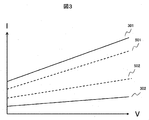
- the first detection unit has the maximum current threshold 401 and the minimum current threshold 402 shown in FIG. In the first embodiment, these two values are constant values (fixed values) regardless of the power supply voltage V applied to the load 3. In contrast, the present embodiment has a maximum current threshold 501 and a minimum current threshold 502 that are proportional to the power supply voltage V applied to the load 3, as shown in FIG.
- the minimum current threshold value 502 is set to a value larger than the current value 302 that can be taken when the load resistance is normal, and is similar to the normal current value 302 in proportion to the power supply voltage V applied to the load 3. Since it changes, it is not detected as an overcurrent.
- the maximum current threshold value 501 is set to a value smaller than the current value 301 that can be obtained when the load resistance is abnormal, and is similar to the abnormal current value 301 in proportion to the power supply voltage V applied to the load 3. Since it changes, it can be detected as an overcurrent.
- the maximum current threshold value 501 and the minimum current threshold value 502 can be defined as resistance values.
- the load power supply voltage value information 202 is simply divided by the current value information 204. Required by Using a microcomputer, it is possible to calculate in real time and diagnose whether the load 3 is abnormal or normal.
- Example 3 Hereinafter, Example 3 will be described with reference to FIG.
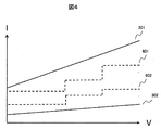
- FIG. 4 simplifies the setting of the maximum current threshold 501 and the minimum current threshold 502 shown in FIG.
- the maximum current threshold 601 and the minimum current threshold 602 shown here have three levels with respect to the power supply voltage V applied to the load 3.
- the maximum current threshold 601 and the minimum current threshold 602 do not need to be calculated in real time using the load power supply voltage value information 202 and the current value information 204, and may be set in advance as three current thresholds for the load power supply voltage value information 202. In the case of realizing with a computer, it can be realized by not increasing the processing load due to the calculation, inputting the load power supply voltage information 202 to the integrated circuit 102, and increasing the current threshold from one to three.
- the threshold value of the power supply voltage V applied to the load 3 is set to three levels. However, it is not always necessary to set three levels. In some cases, two levels are sufficient. By doing so, it is possible to support a wide range of power supply voltages.
Landscapes
- Physics & Mathematics (AREA)
- General Physics & Mathematics (AREA)
- Engineering & Computer Science (AREA)
- Power Engineering (AREA)
- Automation & Control Theory (AREA)
- Mechanical Engineering (AREA)
- Measurement Of Current Or Voltage (AREA)
- Emergency Protection Circuit Devices (AREA)
- Electronic Switches (AREA)
Abstract
Description
Claims (7)
- 外部素子を駆動するための駆動素子と、
前記外部素子を流れる電流値を検出するための電流検出部と、
前記電流値の情報を用いて、前記駆動素子へ制御指令を送信する制御部と、を有する車載電子制御装置において、
前記電流検出部から得られる電流値情報が、前記外部素子の電流の閾値以上であることで前記外部素子の異常を検出する第一検出手段と、
前記電流値情報と前記外部素子に印加される電源電圧情報で前記外部素子の抵抗値を演算し、前記外部素子の抵抗の閾値以下であることで異常を検出する第二検出手段と、
を備えることを特徴とする車載電子制御装置。 - 前記制御部を備える集積回路と、
前記集積回路から前記電流値情報を取得する演算装置と、を備え、
前記集積回路が第一検出手段を実行し、
前記演算装置が第二検出手段を実行する請求項1に記載の車載電子制御装置。 - 前記外部素子に印加される電圧が所定の電圧を上回る場合には前記第一検出手段を実行し、前記第二検出手段は実行せず、
前記外部素子に印加される電圧が所定の電圧以下である場合には、少なくとも第二の検出手段を実行する請求項2に記載の車載電子制御装置。 - 前記外部素子に印加される電圧が所定の電圧以下である場合には、第一と第二の検出手段の双方を実行し、何れかが異常と検知した場合には、前記外部素子が異常であると判断する請求項3に記載の車載電子制御装置。
- 前記所定の電圧は、前記外部素子が異常のときの電流値が、前記外部素子の異常を判断する電流の最大閾値と交差する電圧以上である請求項3又は4に記載の車載電子制御装置。
- 外部素子を駆動するための駆動素子と、
前記外部素子を流れる電流値を検出するための電流検出部と、
前記電流値の情報を用いて、前記駆動素子へ制御指令を送信する制御部と、を有する車載電子制御装置において、
前記電流検出部から得られる電流値情報が、前記外部素子の電流の閾値以上であることで前記外部素子の異常を検出する検出手段を備え、
前記検出手段は、
前記外部素子に印加される電源電圧が低い場合には、前記外部素子の異常を判断する電流の閾値を低く設定し、
前記外部素子に印加される電源電圧が高い場合には、前記外部素子の異常を判断する電流の閾値を高く設定する、閾値電流が電圧に比例した関係を備える車載電子制御装置。 - 外部素子を駆動するための駆動素子と、
前記外部素子を流れる電流値を検出するための電流検出部と、
前記電流値の情報を用いて、前記駆動素子へ制御指令を送信する制御部と、を有する車載電子制御装置において、
前記電流検出部から得られる電流値情報が、前記外部素子の電流の閾値以上であることで前記外部素子の異常を検出する検出手段を備え、
前記検出手段は、前記外部素子に印加される電源電圧情報により、前記外部素子の異常を判断する電流の閾値を切替える機能を有する車載電子制御装置。
Priority Applications (3)
| Application Number | Priority Date | Filing Date | Title |
|---|---|---|---|
| US17/255,321 US11935338B2 (en) | 2018-07-13 | 2019-06-24 | Automotive electronic control unit |
| JP2020530074A JP7055873B2 (ja) | 2018-07-13 | 2019-06-24 | 車載電子制御装置 |
| CN201980040715.0A CN112385146B (zh) | 2018-07-13 | 2019-06-24 | 车载电子控制装置 |
Applications Claiming Priority (2)
| Application Number | Priority Date | Filing Date | Title |
|---|---|---|---|
| JP2018132855 | 2018-07-13 | ||
| JP2018-132855 | 2018-07-13 |
Publications (1)
| Publication Number | Publication Date |
|---|---|
| WO2020012929A1 true WO2020012929A1 (ja) | 2020-01-16 |
Family
ID=69143060
Family Applications (1)
| Application Number | Title | Priority Date | Filing Date |
|---|---|---|---|
| PCT/JP2019/024869 Ceased WO2020012929A1 (ja) | 2018-07-13 | 2019-06-24 | 車載電子制御装置 |
Country Status (4)
| Country | Link |
|---|---|
| US (1) | US11935338B2 (ja) |
| JP (1) | JP7055873B2 (ja) |
| CN (1) | CN112385146B (ja) |
| WO (1) | WO2020012929A1 (ja) |
Families Citing this family (1)
| Publication number | Priority date | Publication date | Assignee | Title |
|---|---|---|---|---|
| EP3582584A1 (en) * | 2018-06-12 | 2019-12-18 | Continental Automotive GmbH | Electric circuit and diagnostic method for an electric load |
Citations (4)
| Publication number | Priority date | Publication date | Assignee | Title |
|---|---|---|---|---|
| JPH04134063U (ja) * | 1991-06-04 | 1992-12-14 | 日本電子機器株式会社 | 酸素センサのヒータの異常診断装置 |
| JP2009074559A (ja) * | 2009-01-16 | 2009-04-09 | Toyota Motor Corp | 排ガスセンサの劣化検出装置 |
| JP2009270932A (ja) * | 2008-05-07 | 2009-11-19 | Denso Corp | ガスセンサ用ヒータの劣化判定装置 |
| JP2010117131A (ja) * | 2008-10-16 | 2010-05-27 | Ngk Spark Plug Co Ltd | ガスセンサシステム |
Family Cites Families (9)
| Publication number | Priority date | Publication date | Assignee | Title |
|---|---|---|---|---|
| JP2001108645A (ja) | 1999-10-13 | 2001-04-20 | Denso Corp | 負荷の異常検出装置 |
| JP3824984B2 (ja) | 2002-09-06 | 2006-09-20 | 三菱電機株式会社 | 排気ガスセンサの温度制御装置 |
| JP4802116B2 (ja) * | 2007-02-21 | 2011-10-26 | 日本特殊陶業株式会社 | ガスセンサの異常診断方法、ガスセンサの異常診断装置 |
| US7802463B2 (en) * | 2007-10-11 | 2010-09-28 | Ngk Spark Plug Co., Ltd. | Sensor control device and air fuel ratio detecting apparatus |
| JP2009278724A (ja) | 2008-05-13 | 2009-11-26 | Diamond Electric Mfg Co Ltd | モータ制御装置 |
| JP2011160289A (ja) * | 2010-02-02 | 2011-08-18 | Anden | 負荷駆動回路 |
| JP6201366B2 (ja) * | 2013-03-27 | 2017-09-27 | 株式会社ジェイテクト | 電気負荷制御装置の過電流異常判定装置、駆動力配分制御装置、および過電流異常判定方法ならびに過電流異常判定プログラム |
| WO2015080599A1 (en) * | 2013-11-26 | 2015-06-04 | Powerbyproxi Limited | Overcurrent protection circuit |
| JP6462473B2 (ja) * | 2015-04-24 | 2019-01-30 | 日立オートモティブシステムズ株式会社 | 負荷駆動装置 |
-
2019
- 2019-06-24 WO PCT/JP2019/024869 patent/WO2020012929A1/ja not_active Ceased
- 2019-06-24 US US17/255,321 patent/US11935338B2/en active Active
- 2019-06-24 JP JP2020530074A patent/JP7055873B2/ja active Active
- 2019-06-24 CN CN201980040715.0A patent/CN112385146B/zh active Active
Patent Citations (4)
| Publication number | Priority date | Publication date | Assignee | Title |
|---|---|---|---|---|
| JPH04134063U (ja) * | 1991-06-04 | 1992-12-14 | 日本電子機器株式会社 | 酸素センサのヒータの異常診断装置 |
| JP2009270932A (ja) * | 2008-05-07 | 2009-11-19 | Denso Corp | ガスセンサ用ヒータの劣化判定装置 |
| JP2010117131A (ja) * | 2008-10-16 | 2010-05-27 | Ngk Spark Plug Co Ltd | ガスセンサシステム |
| JP2009074559A (ja) * | 2009-01-16 | 2009-04-09 | Toyota Motor Corp | 排ガスセンサの劣化検出装置 |
Also Published As
| Publication number | Publication date |
|---|---|
| US11935338B2 (en) | 2024-03-19 |
| CN112385146B (zh) | 2025-01-07 |
| US20210272395A1 (en) | 2021-09-02 |
| JPWO2020012929A1 (ja) | 2021-06-10 |
| CN112385146A (zh) | 2021-02-19 |
| JP7055873B2 (ja) | 2022-04-18 |
Similar Documents
| Publication | Publication Date | Title |
|---|---|---|
| US7336055B2 (en) | Method for detecting abnormality of temperature sensors, and power supply apparatus | |
| JP4094538B2 (ja) | 空燃比センサの故障診断装置 | |
| JP5776705B2 (ja) | 温度検出装置 | |
| US7573275B2 (en) | Temperature sensor control apparatus | |
| JP6269040B2 (ja) | 電流センサのスタック故障診断装置及び診断方法 | |
| JP3988609B2 (ja) | 酸素センサの異常検出装置 | |
| US7002352B2 (en) | Reference voltage diagnostic suitable for use in an automobile controller and method therefor | |
| KR20090012456A (ko) | 고전압 사용 차량의 절연내력 측정 시스템 및 방법 | |
| US7445383B2 (en) | Method and device for diagnosing an external temperature sensor | |
| US20170363481A1 (en) | Fault Detection Apparatus | |
| WO2020012929A1 (ja) | 車載電子制御装置 | |
| US20060149427A1 (en) | Apparatus for monitoring a supply system, in particular a motor-vehicle electrical system, and method for monitoring a supply system for this type | |
| WO2020262096A1 (ja) | 温度検出装置およびそれを備えた電子制御装置 | |
| JP5989171B1 (ja) | 電流検出回路、及びその回路を備えた車両用電子制御装置 | |
| JP2009031153A (ja) | 酸素センサの制御装置 | |
| JP2009090823A (ja) | センサ識別機能付き車両用エアコン制御装置 | |
| JP2000197201A (ja) | 電気自動車の地絡検出回路 | |
| JP4830676B2 (ja) | 排気ガスセンサの故障診断装置 | |
| JP4824504B2 (ja) | 温度センサ制御装置 | |
| JP2013205345A (ja) | 温度検出装置 | |
| JP4877291B2 (ja) | ヒータ劣化検出装置 | |
| US20250189590A1 (en) | Method for Determining a Thermal Runaway of an Electric Energy Storage Unit of an at Least Partially Electrically Operated Motor Vehicle, Computer Program Product, and Electronic Computing Device | |
| JPH0988708A (ja) | 温度センサ回路 | |
| US20150153751A1 (en) | Power supply circuit and electronic control unit employing the same | |
| JP2546395B2 (ja) | 酸素センサのヒータ制御故障診断装置 |
Legal Events
| Date | Code | Title | Description |
|---|---|---|---|
| 121 | Ep: the epo has been informed by wipo that ep was designated in this application |
Ref document number: 19834872 Country of ref document: EP Kind code of ref document: A1 |
|
| ENP | Entry into the national phase |
Ref document number: 2020530074 Country of ref document: JP Kind code of ref document: A |
|
| NENP | Non-entry into the national phase |
Ref country code: DE |
|
| 122 | Ep: pct application non-entry in european phase |
Ref document number: 19834872 Country of ref document: EP Kind code of ref document: A1 |
|
| WWG | Wipo information: grant in national office |
Ref document number: 201980040715.0 Country of ref document: CN |