WO2020009143A1 - ガラス物品の製造方法、製造装置及びガラス基板 - Google Patents
ガラス物品の製造方法、製造装置及びガラス基板 Download PDFInfo
- Publication number
- WO2020009143A1 WO2020009143A1 PCT/JP2019/026441 JP2019026441W WO2020009143A1 WO 2020009143 A1 WO2020009143 A1 WO 2020009143A1 JP 2019026441 W JP2019026441 W JP 2019026441W WO 2020009143 A1 WO2020009143 A1 WO 2020009143A1
- Authority
- WO
- WIPO (PCT)
- Prior art keywords
- molten glass
- glass
- tank
- flow path
- transfer
- Prior art date
- Legal status (The legal status is an assumption and is not a legal conclusion. Google has not performed a legal analysis and makes no representation as to the accuracy of the status listed.)
- Ceased
Links
Images






Classifications
-
- C—CHEMISTRY; METALLURGY
- C03—GLASS; MINERAL OR SLAG WOOL
- C03B—MANUFACTURE, SHAPING, OR SUPPLEMENTARY PROCESSES
- C03B7/00—Distributors for the molten glass; Means for taking-off charges of molten glass; Producing the gob, e.g. controlling the gob shape, weight or delivery tact
- C03B7/14—Transferring molten glass or gobs to glass blowing or pressing machines
-
- C—CHEMISTRY; METALLURGY
- C03—GLASS; MINERAL OR SLAG WOOL
- C03B—MANUFACTURE, SHAPING, OR SUPPLEMENTARY PROCESSES
- C03B17/00—Forming molten glass by flowing-out, pushing-out, extruding or drawing downwardly or laterally from forming slits or by overflowing over lips
- C03B17/06—Forming glass sheets
-
- C—CHEMISTRY; METALLURGY
- C03—GLASS; MINERAL OR SLAG WOOL
- C03B—MANUFACTURE, SHAPING, OR SUPPLEMENTARY PROCESSES
- C03B5/00—Melting in furnaces; Furnaces so far as specially adapted for glass manufacture
- C03B5/16—Special features of the melting process; Auxiliary means specially adapted for glass-melting furnaces
- C03B5/167—Means for preventing damage to equipment, e.g. by molten glass, hot gases, batches
-
- C—CHEMISTRY; METALLURGY
- C03—GLASS; MINERAL OR SLAG WOOL
- C03B—MANUFACTURE, SHAPING, OR SUPPLEMENTARY PROCESSES
- C03B5/00—Melting in furnaces; Furnaces so far as specially adapted for glass manufacture
- C03B5/16—Special features of the melting process; Auxiliary means specially adapted for glass-melting furnaces
- C03B5/167—Means for preventing damage to equipment, e.g. by molten glass, hot gases, batches
- C03B5/1672—Use of materials therefor
- C03B5/1675—Platinum group metals
-
- C—CHEMISTRY; METALLURGY
- C03—GLASS; MINERAL OR SLAG WOOL
- C03B—MANUFACTURE, SHAPING, OR SUPPLEMENTARY PROCESSES
- C03B5/00—Melting in furnaces; Furnaces so far as specially adapted for glass manufacture
- C03B5/16—Special features of the melting process; Auxiliary means specially adapted for glass-melting furnaces
- C03B5/18—Stirring devices; Homogenisation
Definitions
- the present invention relates to a method for manufacturing a glass article, and more particularly, to a technique for setting a transfer device having a fining tank and a stirring pot to an appropriate state at the time of startup before starting operation.
- the molten glass that has flowed out of the melting furnace is supplied to a forming apparatus using a transfer apparatus.
- the transfer device has a transfer container for transferring the molten glass.
- Patent Document 1 discloses a transfer device including a fining tank, a stirring pot, a cooling pipe, a pot, and the like in order from the upstream side as a transfer container.
- the transfer channel including these transfer containers is generally formed of a member made of a noble metal (for example, platinum or a platinum alloy).
- Patent Document 2 discloses that molten glass is sequentially introduced into a glass supply pipe 1, a fining tank, a glass supply pipe 2, a stirring pot, and a glass supply pipe 3 which are transfer containers at the time of startup. ing. Further, the document describes that during the process of introducing the molten glass into each of these transfer containers, a temperature increase control is performed to raise the temperature of each transfer container to the operating temperature.
- Patent Document 2 there is still a problem to be solved no matter how strictly the temperature increase control is performed to raise the temperature of each transfer container to the operating temperature at the time of startup.
- the refining tank can be at the highest temperature during operation.
- the temperature of the fining tank tends to be higher than that of other transfer containers. Therefore, during the process of introducing the molten glass into the fining tank at the time of startup, the fining tank becomes empty and oxidized easily. As a result, foreign matter such as platinum may be mixed into the molten glass in the refining tank, which may lead to a defective product or a lower quality.
- the form and amount of the platinum foreign matter contained in the glass substrate should be appropriately adjusted. It is important to do.
- the first object of the present invention is to create a state in which oxidation is unlikely to occur in the fining tank during the process of introducing the molten glass into the fining tank during startup, and to mix foreign matter into the molten glass in the fining tank. As much as possible.
- a second object of the present invention is to improve the quality of a glass substrate by appropriately setting the form and amount of platinum foreign matter contained in the glass substrate.
- a method according to the present invention devised to solve the first problem includes a melting step of heating and melting a glass raw material in a melting furnace to produce a molten glass, and a fining apparatus disposed downstream of the melting furnace.
- the introduction step further includes the step of: melting the molten glass in the fining tank by blocking a molten glass with a resistance member disposed in a flow path between the fining tank and the stirring pot. Characterized in further comprising a maintenance step of maintaining the liquid level of the glass in the liquid level at the time of execution of the transfer step and the molding step.
- the molten glass that has flowed out of the melting furnace and started to be introduced into the fining tank in the introduction step at the time of startup is blocked by the resistance member between the fining tank and the stirring pot. Therefore, the molten glass is stored in the fining tank on the upstream side of the resistance member, and the liquid level of the molten glass in the fining tank is quickly reduced during operation (at the time of executing the transfer step and the forming step). Can be reached and maintained.
- oxidation in the fining tank is less likely to occur, and a situation in which devitrified foreign substances (such as platinum foreign substances) are mixed in the molten glass can be efficiently avoided at an appropriate place.
- the resistance member is a gate that opens and closes the flow path, and adjusts an opening degree of the flow path with the gate to adjust the liquid level of the molten glass in the fining tank to the transfer step. It is preferable to maintain the liquid level at the time of performing the molding step.
- the molten glass in the refining tank is transferred to the stirring pot and discharged from a drain hole opened on the inner bottom surface of the stirring pot.
- the molten glass in the refining tank can be kept flowing. This makes it difficult for the molten glass to stay in the fining tank for a long period of time and become boiled down (cooked), thereby being unlikely to be transformed into foreign glass.
- the fining tank in the maintenance step is filled with molten glass, similarly to the fining tank in the transfer step when the forming step is performed.
- the liquid level of the molten glass in the fining tank is the height of the top of the inner surface of the fining tank.
- the temperature of the molten glass in the refining tank in the maintaining step is lower than the temperature of the molten glass in the refining tank in the transfer step when the forming step is performed.
- An apparatus for manufacturing a glass article comprising: a resistance member further provided in a flow path between the fining tank and the stirring pot to block molten glass flowing out of the melting furnace.
- oxidation in the fining tank is less likely to occur, and the situation in which devitrified foreign substances (platinum foreign substances, etc.) are mixed in the molten glass can be efficiently performed in place. Can be avoided.
- the resistance member is a gate that opens and closes the flow path.
- the degree of obstruction of the flow of the molten glass can be easily variably controlled only by providing a simple structure for sliding the gate.
- the gate can be inserted and removed through an opening provided at an upper portion of a peripheral wall forming the flow path, and the cover covers the opening when the gate is removed. It is preferable to configure.
- the lid has a vent passage for discharging gas existing in the passage.
- the gas mainly, vaporized molten glass
- the vent flow path in preference to the gap along the lower surface of the lid.
- the periphery of the opening on the outer peripheral side of the peripheral wall is covered with a refractory, and a cooling pipe for cooling the electrode for heating the peripheral wall with electric current is disposed around the refractory. For this reason, the gas flowing out of the gap along the lower surface of the lid may erode the refractory and hit the cooling pipe.
- the cooling pipe may be damaged or broken due to corrosion due to oxidation.
- the vent flow path by providing the vent flow path, the amount of gas flowing out of the gap along the lower surface of the lid can be reduced to a small amount, so that damage to the cooling pipe can be suppressed.
- the lid has a side wall portion surrounding the space above the opening from the outer peripheral side, and a ceiling wall portion covering above the side wall portion, and the outlet of the vent flow path is provided. Preferably, it is provided on the side wall.
- the glass substrate according to the present invention which has been devised to solve the second problem, has a ratio of one or more platinum foreign substances having a ratio of a major axis dimension to a minor axis dimension of 15 or more and a major axis dimension of 3 ⁇ m or more. / Kg or less.
- This glass substrate was obtained as a result of the inventor's intense research and ascertaining the form and content of platinum foreign matter, which is the biggest cause of quality deterioration. Therefore, this glass substrate has extremely high quality as compared with the conventional glass substrate.
- the present invention for solving the first problem, in the process of introducing molten glass into the fining tank at the time of startup, a state in which oxidation is unlikely to occur in the fining tank is created. Foreign matter is suppressed as much as possible. According to the present invention for solving the second problem, the form and amount of the platinum foreign matter contained in the glass plate become appropriate, and the quality of the glass plate is improved.
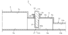
- FIG. 4 is a schematic longitudinal sectional front view of an essential part taken along line AA of FIG. 3.
- FIG. 8 is a longitudinal sectional front view taken along the line BB of FIG. 7.
- FIG. 14 is a vertical sectional front view taken along the line CC in FIG. 13. It is a vertical front view which shows the 3rd example of the upper structure of the attached tank which is a component of the manufacturing apparatus for implementing the manufacturing method of the glass article which concerns on embodiment of this invention.
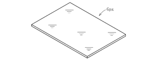
- FIG. 18 is a longitudinal sectional front view taken along the line DD in FIG. 17. It is a perspective view showing a glass plate concerning an embodiment of the present invention.
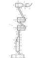
- FIG. 1 illustrates an apparatus for manufacturing a glass article according to the present invention.
- the manufacturing apparatus 1 is roughly divided into a melting furnace 2 provided at an upstream end for heating and melting a glass material, and a molten glass Gm flowing out of the melting furnace 2 being transported downstream.
- a forming means 4 for forming the molten glass Gm supplied from the transfer device 3 into a band-shaped plate glass Gp.
- the transfer device 3 includes a refining tank 5, an additional tank 6 attached to the refining tank 5, a plurality of (two in the example in the figure) stirring pots 7, 8, and a cooling pipe 9 in order from the upstream side as transfer containers. , A pot 10.
- Each of these transfer containers 5 to 10 has an inlet into which the molten glass Gm flows, and an outlet through which the molten glass Gm flows out.
- the fining tank 5 is for removing bubbles in the molten glass
- an attached tank 6 is connected downstream of the fining tank 5.
- a first stirring pot 7 on the upstream side and a second stirring pot 8 on the downstream side for homogenizing the molten glass Gm are disposed downstream of the attachment tank 6.
- the stirring pots 7, 8 rotating around the axis are accommodated in the stirring pots 7, 8 during operation of the manufacturing apparatus 1, respectively.
- a cooling pipe 9 is arranged adjacently, and on the downstream side of the cooling pipe 9, a pot 10 is arranged adjacently as a volume part for mainly adjusting the viscosity of the molten glass Gm. Have been.
- the downstream side of the cooling pipe 9 is inclined upward.
- the forming means 4 has a formed body 11 for forming the molten glass Gm by flowing down by the overflow down draw method, and a large-diameter introduction pipe 12 for guiding the molten glass Gm to the formed body 11.
- the molten glass Gm is supplied to the introduction pipe 12 from the pot 10 of the transfer device 3.
- FIG. 2 is an enlarged vertical sectional view of the transfer device 3.
- the outlet 2b of the melting furnace 2 communicates with the inlet 5a of the fining tank 5 via the upstream connection pipe 13.
- a vent is provided on the upper surface portion 5n of the fining tank 5 for mainly discharging gas generated from bubbles in the molten glass.
- the outlet 5b of the fining tank 5 overlaps and communicates with the inlet 6a of the attached tank 6.
- the outlet 6b of the attachment tank 6 communicates with the inlet 7a of the first stirring pot 7 via the intermediate connection pipe 14.
- the inflow port 7a of the first stirring pot 7 is provided on the upper part of the peripheral wall.
- the outlet 7b of the first stirring pot 7 communicates with the inlet 8a of the second stirring pot 8 via the downstream connection pipe 15.
- An outlet 7b of the first stirring pot 7 is provided at a lower portion of the peripheral wall, and an inlet 8a of the second stirring pot 8 is provided at an upper portion of the peripheral wall.
- These stirring pots 7, 8 are arranged at the same height.
- the downstream connection pipe 15 has a downstream side inclined upward.
- the outlet 8b of the second stirring pot 8 overlaps and communicates with the inlet 9a of the cooling pipe 9.
- the outlet 8b of the second stirring pot 8 is provided at a lower portion of the peripheral wall.
- the downstream side of the cooling pipe 9 is inclined upward.
- the outlet 9b of the cooling pipe 9 overlaps and communicates with the inlet 10a of the pot 10.
- the pot 10 has an upper large diameter portion 10x and a lower small diameter portion 10y.
- the inlet 10a of the pot 10 is provided on the peripheral wall of the large diameter portion 10x, and the outlet 10b is provided at the lower end of the small diameter portion 10y.
- the small diameter portion 10y of the pot 10 is inserted into the introduction pipe 12 of the forming means 4. The lower end of the small diameter portion 10y is immersed in the molten glass Gm in the introduction pipe 12.
- the transfer flow path composed of the transfer vessels 5 to 10 and the connection pipes 13 to 15, at least a portion (in this embodiment, the entire inner surface of the transfer flow path) in contact with the molten glass Gm has a thin noble metal (for example, it is formed of a member made of platinum or a platinum alloy. The periphery of those members is covered with a refractory (not shown).
- the transfer flow path is electrically heated so that the temperature of each transfer container 5 to 10 and each of the connection pipes 13 to 15 can be adjusted.
- the manufacturing apparatus 1 having the above configuration executes the following steps. That is, in the method for producing a glass article according to the present invention, the melting step of heating and melting the glass raw material in the melting furnace 2 to generate the molten glass Gm, and the forming apparatus by which the molten glass Gm flowing out of the melting furnace 2 is formed by the transfer device 3 4 and a forming step of forming the molten glass Gm supplied from the transfer device 3 into a predetermined shape by the forming means 4.
- This manufacturing method further includes an introduction step of introducing the molten glass Gm flowing out of the melting furnace 2 into the transfer device 3 before the start of the transfer step and the forming step (when starting up before the start of operation). In this introduction step, the following is performed.
- FIGS. 3 and 4 illustrate a state in which the molten glass Gm has not flowed out of the melting furnace 2 to the transfer device 3 before the start of the transfer process, and the molten glass Gm does not exist in the transfer device 3.
- a gate 16 as a resistance member is inserted into the attachment tank 6.
- the gate 16 has a role of preventing the flow of the molten glass Gm.
- the gap 17 between the bottom surface 16m of the gate 16 and the lower surface 6m of the attachment tank 6 is a passage (a narrowed passage) through which the molten glass Gm flows.
- the gate 16 opens and closes the attached tank 6 by moving up and down by a lifting mechanism (not shown), and adjusts the opening degree of the attached tank 6. Thereby, the gate 16 can adjust the flow rate of the molten glass Gm.
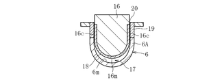
- a thin plate material 18 made of platinum or a platinum alloy is adhered to the front surface portion 16a and the back surface portion 16b of the refractory forming the gate 16, the both side surface portions 16c, and the bottom surface portion 16m.
- the gate 16 has a U-shape from both sides 16c to the bottom 16m.
- the refining tank 5 has a pipe shape.
- the attachment tank 6 has a pipe shape, but only a portion where the gate 16 is inserted has a U-shape as shown in FIG.
- the passage area of the fining tank 5 is larger than the passage area of the attachment tank 6, and the passage area of the attachment tank 6 is larger than the passage area of the intermediate connection pipe 14.
- the lowest part of the lower surface 5m of the fining tank 5, the lowest part of the lower part 6m of the attachment tank 6, and the lower part of the lower part 14m of the intermediate connection pipe 14 are at the same height position.
- the uppermost portion of the upper surface portion 5n of the refining tank 5 is higher than the uppermost portion of the upper surface portion 6n of the additional tank 6, and the uppermost portion of the upper surface portion 6n of the additional tank 6 is the highest of the upper surface portion 14n of the intermediate connection pipe 14. Higher than the top.
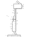
- FIG. 5 illustrates a state in which the molten glass Gm flowing out of the melting furnace 2 is introduced into the fining tank 5 and then flows into the first stirring pot 7 and is discharged (first flowing step).
- the stirring blade 7x is detached from the first stirring pot 7 (the same applies to the stirring blade 8x of the second stirring pot 8).
- the molten glass Gm flowing out of the melting furnace 2 flows into the refining tank 5 through the upstream connection pipe 13.
- the liquid level of the molten glass Gm in the refining tank 5 is in a low state. Therefore, the molten glass Gm flows around the lower surface 6 m of the fining tank 5 and flows into the attached tank 6.
- the flow of the molten glass Gm that has flowed into the additional tank 6 is blocked by the gate 16 and is blocked.
- the molten glass Gm is stored upstream of the gate 16.
- the inside of the refining tank 5 is filled with the molten glass Gm as shown in FIG. 5 (maintenance step).
- the molten glass Gm has the highest temperature in the refining tank 5 of the transfer device 3, so that even in the introduction step before the start of the transfer step, the molten glass Gm remains in the refining tank 5. It must be the highest temperature.
- the temperature of the molten glass Gm in the fining tank 5 is, for example, 1500 to 1650 ° C. Therefore, the fining tank 5 is the most easily oxidized in the transfer device 3.
- the fining tank 5 is filled with the molten glass Gm in a short time. Therefore, oxidation of the fining tank 5 can be suppressed.
- the molten glass Gm that has passed through the gate 16 flows into the first stirring pot 7 via the downstream portion of the attachment tank 6 and the intermediate connection pipe 14. Then, the molten glass Gm is discharged downward through a drain hole 7g opened in the inner bottom surface 7m of the first stirring pot 7. At this time, the molten glass Gm is maintained at a low liquid level (lower than during operation) in the downstream portion of the attachment tank 6, the intermediate connection pipe 14, and the first stirring pot 7.
- the temperature of the molten glass Gm in the intermediate connection pipe 14 and the first stirring pot 7 is, for example, 1200 to 1400 ° C. For this reason, the intermediate connection pipe 14 and the first stirring pot 7 are less likely to be oxidized than the fining tank 5, so that foreign matter such as platinum butter is less likely to be mixed, and even if generated, it is slight.
- the molten glass Gm constantly flows in the fining tank 5 by continuously discharging the molten glass Gm from the first stirring pot 7. This makes it difficult for the molten glass Gm to stay in the fining tank 5 for a long period of time and become a boiled state (cooked state), so that it is unlikely to be transformed into a foreign glass.
- the temperature of the molten glass Gm in the fining tank 5 is, for example, 50 to 200 ° C. lower than the temperature during operation. Has been lowered. Thereby, the flow speed of the molten glass Gm decreases, and the flow rate of the molten glass Gm flowing out of the fining tank 5 per unit time can be reduced.
- a centering step of centering the molded body 11 and an unillustrated rough cutter (apparatus for cutting glass) disposed below the formed body 11 is performed.
- This centering step requires, for example, 3 to 6 hours.
- the molten glass Gm is continuously discharged from the drain hole 7 g of the first stirring pot 7 in a state where the fining tank 5 is filled. For this reason, it is possible to avoid a situation in which a foreign substance such as platinum butter enters the molten glass Gm in the refining tank 5 during the execution of the centering step. Further, it is possible to prevent the molten glass Gm from being boiled down and deteriorated in the fining tank 5.
- the gate 16 is removed from the attachment tank 6, and the discharge of the molten glass Gm from the drain hole 7g is stopped by closing the drain hole 7g of the first stirring pot 7. Further, the temperature of the transfer containers 5 to 10 and the connection pipes 13 to 15 are raised to the operating temperature. As a result, the molten glass Gm flows into the forming means 4 via the second stirring pot 8, the cooling pipe 9 and the pot 10, and the molten glass Gm in the transfer containers 6 to 10 and the connection pipes 14 and 15 are operated. (Second inflow step). Thereafter, the transfer step and the forming step (operation) are started.
- a rectangular rectangular tubular portion 19 having a central axis extending vertically is attached to an upper portion of the peripheral wall 6A forming the attached tank 6.
- An opening 20 for inserting and removing the gate 16 is provided at an upper end of the cylindrical portion 19. The opening 20 is covered with the lid when the gate 16 is removed (when the transfer step and the molding step are performed).
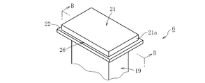
- FIG. 7 is a perspective view of a main part showing a first example of the upper structure of the tubular portion 19, and FIG. 8 is a longitudinal sectional front view taken along line BB of FIG.
- the opening 20 at the upper end of the tubular portion 19 is covered by a lid 21.
- the tubular portion 19 has a flange 22 at an upper end.
- the cover 21 can be easily attached and detached while covering the opening 20.
- the tubular portion 19 is formed of platinum or a platinum alloy.
- the flange 22 is formed of platinum, a platinum alloy, or another metal.
- the opening area of the opening 20 of the cylindrical portion 19 is substantially the same size as the pipe area of the cylindrical portion 19, but the former may be smaller than the latter or It can be large.
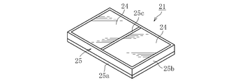
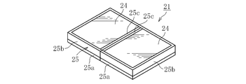
- FIG. 9 is a perspective view showing the configuration of the lid 21.
- the lid 21 is composed of a plurality (two in the illustrated example) of refractories 24 and a thin plate 25 as a covering material made of platinum or a platinum alloy covering the refractories 24.
- a lower thin plate 25 a covering the lower surfaces of the two refractories 24, an outer peripheral thin plate 25 b covering the entire outer peripheral surfaces of the two refractories 24, and an interposition between the two refractories 24.
- Partition thin plate 25c Partition thin plate 25c. These thin plates 25a, 25b, 25c are integrated. As shown in FIG.
- the two refractories 24 are separately covered with a lower thin plate 25a, an outer peripheral thin plate 25b, and a partition thin plate 25c, and the two partition thin plates 25c are brought into contact with each other so as to be separated from each other, or It is good also as a structure joined so that it may not separate.
- the thin plate 25 may cover the entire surface including the upper surface of the refractory 24, or may cover only the lower surface of the refractory 24.
- the covering material is not limited to the thin plate 25, and may be a layer made of platinum or a platinum alloy formed by spraying the refractory 24.
- the refractory 24 is a refractory made of, for example, dense zircon, mullite, alumina, or zirconia (the same applies to “refractory” described below).
- the following operational effects can be obtained. While the transfer step and the forming step are being performed, the opening 20 of the tubular portion 19 in the attachment tank 6 is covered by the lid 21. Therefore, the adverse effects that can be caused by the opening 20 being opened are avoided. Specifically, even if tin oxide or the like remaining in the molten glass Gm in the attachment tank 6 volatilizes, the volatile matter is liquefied because the vicinity of the opening 20 of the cylindrical portion 19 is always maintained at a high temperature. Alternatively, it is possible to prevent solidification and adhesion to the inner surface near the opening 20. For this reason, it is possible to appropriately prevent the attached volatile matter from falling into the molten glass Gm and becoming a foreign substance.
- the amount of heat radiation from the opening 20 is significantly reduced, an effect of preventing devitrification near the liquid level GL of the molten glass Gm can be obtained. As a result, it is possible to improve the quality of the glass article (glass plate) as a product or the yield of the product.
- the lid 21 since the lower surface of the lid 21 that is easily eroded is covered with a thin plate (covering material) 25 made of platinum or a platinum alloy, erosion or the like of the lid 21 is efficiently suppressed and durability is improved. Can be improved. In this case, if the entire lid 21 is made of platinum or a platinum alloy, the cost and weight will increase. However, the cost can be reduced by covering the refractory 24 with a thin plate 25 made of platinum or a platinum alloy. And contribute to weight reduction.
- the gas inside may flow out through the gap 26 between the upper end of the tubular portion 19 and the lid 21.
- This gas is mainly steam vaporized by the molten glass Gm, and includes gas generated from bubbles in the molten glass Gm. If the gas flows out through the gap 26 as shown by the arrow a, the following adverse effects may occur. Strictly, the periphery of the cylindrical portion 19 has a structure as shown in FIG.
- a peripheral wall flange 27 extending outward from the peripheral wall 6A is formed, and an electrode (not shown) for electrically heating the peripheral wall 6A is formed on the peripheral wall flange 27.
- the peripheral wall flange 27 is provided with a cooling pipe 28 through which a cooling liquid circulates in the pipe.
- a heat insulating brick 29 made of a refractory is disposed between the tubular portion 19 and the peripheral wall flange 27 so as to cover the outer peripheral side of the peripheral wall 6A.
- a peripheral wall flange 30, a cooling pipe 31, and a heat insulating brick 32 are similarly disposed on the downstream side of the cylindrical portion 19, and another heat insulating brick 33 is disposed on the outer peripheral side of the heat insulating brick 32 here.
- the peripheral wall flange 27 on the upstream side is closer to the tubular portion 19 than the peripheral wall flange 30 on the downstream side. Therefore, as described above, the gas that has flowed in the direction of the arrow a from the gap 26 between the upper end of the tubular portion 19 and the lid 21 erodes the upstream insulating brick 29 and cools the upstream cooling pipe 28. Might be hit.
- the cooling liquid may leak out due to corrosion of the upstream cooling pipe 28 by oxidation or the like. If the gas flowing out of the gap 26 erodes the heat insulating bricks 32 and 33 in a large amount on the downstream side, the cooling liquid may leak out of the cooling pipe 31 on the downstream side similarly due to corrosion or the like.
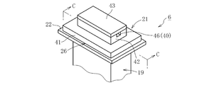
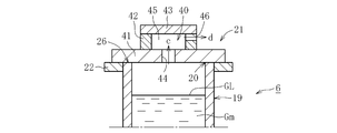
- FIG. 13 is a perspective view showing a second example of the upper structure of the tubular portion 19, and FIG. 14 is a longitudinal sectional front view taken along line CC of FIG.
- a vent channel 40 is provided in the lid 21. More specifically, the lid 21 includes a rectangular flat base wall 41 that covers the opening 20 of the cylindrical portion 19, and a rectangular frame or rectangular cylindrical side wall that is installed on the base wall 41. 42, and a rectangular flat ceiling wall 43 that covers the upper side of the side wall 42.
- the vent flow path 40 includes an inlet 44, an inner space 45 communicating with the inlet, and an outlet 46 communicating with the inner space 45.
- the inflow port 44 is a through hole formed in the center of the base wall 41.
- the internal space 45 is a space surrounded by the side wall 42 and the ceiling wall 43.
- the outflow port 46 is a cutout portion formed at one upper portion around the side wall portion 42. In this case, the inlet 44 and the outlet 46 have different positions in plan view.
- the central axis of the inflow port 44 extends in the vertical direction, while the central axis of the inflow port 46 extends in the horizontal direction. Therefore, the gas flow direction at the inflow port 44 is upward (along arrow c) substantially along the vertical direction, whereas the gas flow direction at the outflow port 46 is horizontal in the horizontal direction. (Direction of arrow d).
- the base wall portion 41 is formed by forming the inflow port 44 at the center of the lid 21 (see FIGS. 9 and 10) in the first example described above.
- the inner peripheral surface of the inflow port 44 is also covered with a covering material of platinum or a platinum alloy.
- both the side wall portion 42 and the ceiling wall portion 43 are preferably formed only of refractory material, but at least a portion of the refractory material that comes into contact with gas is covered with a covering material of platinum or a platinum alloy. You may.
- the opening area of the outlet 46 is smaller than the opening area of the inlet 44.
- the outlet 46 is not limited to one location around the side wall portion 42, and may be formed at a plurality of locations around the sidewall portion 42.
- the following operation and effect can be obtained.
- the gas in the attachment tank 6 flows into the internal space 45 from the inlet 44 of the vent flow path 40 prior to the gap 26, and then flows out of the outlet 46. Therefore, the outflow amount of the gas from the gap 26 becomes a small amount. Further, since the gas flow direction (d direction) at the outlet 46 is orthogonal to the upstream and downstream directions, the gas flowing out from the outlet 46 is supplied to the upstream cooling pipe 28 and the downstream cooling pipe 31. It does not go in any direction. Under these circumstances, the situation where the gas hits the cooling pipes 28 and 31 is avoided.
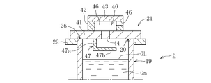
- FIG. 15 is a longitudinal sectional front view showing a third example of the upper structure of the tubular portion 19.
- the configuration according to the third example is different from the configuration according to the second example described above in that a receiving member 47 is installed on the base wall portion 41 of the lid 21. is there.
- the receiving member 47 has a hanging portion 47a extending downward from a lower portion of the base wall portion 41, and a receiving portion 47b extending laterally (horizontally) from the lower end of the hanging portion 47a.
- the receiving portion 47b is arranged in a space above the liquid level GL of the molten glass Gm.
- the area (area in plan view) of the receiving portion 47b is larger than the opening area of the inflow port 44, and the inflow port 44 fits in the upper surface area of the receiving portion 47b in plan view.
- the other configuration is the same as the configuration according to the above-described second example. Therefore, the components common to the two examples are denoted by the same reference numerals in FIG. 15 and the description thereof is omitted.
- the configuration according to the third example even if it falls through the inlet 44 due to a large amount of volatile matter attached to the inner peripheral surface of the inlet 44, the volatile matter is received by the receiving member 47. It is received by the stopping portion 47b. Therefore, it is possible to more reliably suppress the situation where the volatiles fall into the molten glass Gm and become platinum foreign matters.
- Other functions and effects are substantially the same as those of the above-described second example.
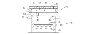
- FIG. 16 is a longitudinal sectional front view showing a fourth example of the upper structure of the tubular portion 19.
- the configuration according to the fourth example is different from the configuration according to the above-described second example in that the position deviated to one side from the central portion of the base wall portion 41 of the lid 21.
- An outlet 44 is formed at a position offset from the center of the ceiling wall 43 toward the other side. Therefore, the positions of the inlet 44 and the outlet 46 in plan view are different.
- the flow direction of the gas at the inflow port 44 is the same as the flow direction of the gas at the outflow port 46, and both directions are substantially upward (along arrow e and arrow f) along the vertical line. It is.
- the notch is not formed in the side wall portion 42.
- the internal space 45 of the vent channel 40 is wider in the lateral direction than in the second example described above.
- the other configuration is the same as that of the above-described second example. Therefore, the same components as those of the second example are denoted by the same reference numerals in FIG. 16 and the description thereof is omitted.
- the inlet 44 and the outlet 46 have different positions in plan view, so the inlet 44 does not exist in the path where the volatiles fall, and the volatiles It is received on the upper surface of the wall portion 41. This prevents the volatiles from falling into the molten glass Gm. Further, since the gas flowing out from the outlet 46 goes upward (in the direction of the arrow f) immediately after the gas flows out, the gas can reliably be prevented from hitting the cooling pipes 28 and 31.
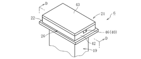
- FIG. 17 is a vertical sectional front view showing a fifth example of the upper structure of the tubular portion 19, and FIG. 18 is a vertical sectional front view cut along the line DD of FIG.
- the configuration according to the fifth example is such that the lid 21 has a rectangular frame-like or rectangular rectangular tubular side wall 42 disposed on the flange 22, and a rectangular flat ceiling wall covering the upper side of the side wall 42. 43.
- the ceiling wall 43 has the same configuration as the lid 21 (see FIGS. 9 and 10) in the first example described above.
- the vent flow path 40 includes an internal space 45 and an outlet 46.
- the internal space 45 is a space surrounded by the side wall 42 and the ceiling wall 43.
- the outflow port 46 is a cutout portion formed at one upper portion around the side wall portion 42.
- the gas in the attachment tank 6 passes through the internal space 45 of the vent flow channel 40 in preference to the gap 26 between the upper end of the tubular portion 19 and the side wall portion 42. Then, it flows out from the outlet 46 to the outside. In this case, even if the volatiles attached to the inner peripheral surface of the outlet 46 fall, the volatiles are deposited on the bottom of the inner peripheral surface of the outlet 46 or the upper end surface of the cylindrical portion 19 (the upper surface of the flange 22 or the like). It is accepted. This prevents the volatiles from falling into the molten glass Gm.
- the space above the opening 20 (the internal space 45) is maintained at a high temperature because it is surrounded by the side wall 42 and the ceiling wall 43. Therefore, the vicinity of the opening 20 is in a state where volatile substances such as tin oxide hardly adhere and aggregation of the volatile substances after the adhesion hardly occurs. This can prevent the volatile substances from adhering or aggregating near the opening 20 and prevent the volatile substances from falling into the molten glass Gm from the inner surface near the opening 20.
- the reason why the gas flowing out from the outlet 46 is unlikely to hit the cooling pipes 28 and 31 is substantially the same as the above-described second example (see FIG. 14).
- the inventor obtained a large number of glass substrates by using the manufacturing apparatus and the manufacturing method having the above configuration. Furthermore, the present inventor has focused on the form and amount of platinum foreign matter contained in these glass substrates, and found a high-quality glass substrate Gpx as shown in FIG. 19 from among these glass substrates.
- the number of platinum foreign particles having a ratio of the major axis dimension to the minor axis dimension of 15 or more and the major axis dimension of 3 ⁇ m or more is 1 / kg or less.
- the number of the platinum foreign substances is preferably 0.05 / kg or less, more preferably 0.01 / kg or less.
- the lower limit of the number of platinum foreign matters may be, for example, 0.0001 / kg or more.
- the number of the platinum foreign substances contained in the glass substrates is a good quality glass substrate.
- the manufacturing apparatus and the manufacturing method according to the present invention the number of the platinum foreign substances contained in those glass substrates is the best glass substrate, It was 0.0005 pieces / kg.
- This glass substrate can be used for flat panel displays such as liquid crystal displays and organic EL displays, organic EL lighting, solar cells, and the like.
- the thickness of the glass substrate is, for example, 0.01 to 10 mm, preferably 0.1 to 3 mm, more preferably 0.2 mm to 1.8 mm, and still more preferably 0.2 mm to 0.5 mm. is there.
- the glass substrate has a rectangular shape, and the lengths of the short side and the long side are preferably 1100 mm or more, more preferably 2200 mm or more.
- the glass substrate is made of, for example, non-alkali glass, soda glass, soda lime glass, borosilicate glass, aluminosilicate glass, and alkali-containing glass.
- non-alkali glass for example, SiO 2 50 to 70%, Al 2 O 3 12 to 25%, B 2 O 3 0 to 12%, Li 2 O + Na 2 O + K 2 O (Li 2 O, the total content of Na 2 O and K 2 O) less than 0 ⁇ 1%, MgO 0 ⁇ 8%, CaO 0 ⁇ 15%, SrO 0 ⁇ 12%, the composition comprising BaO 0 ⁇ 15% may be employed.
- Both surfaces of the glass substrate are preferably fired surfaces, that is, a glass substrate formed by an overflow downdraw method is preferable.
- the present invention is not limited to the above embodiment, and various variations are possible as exemplified below.
- the gate 16 is provided in the attachment tank 6, but the location of the gate 16 is another location as long as it is a flow path between the fining tank 5 and the first stirring pot 7. Is also good.
- the gate 16 is used as the resistance member.
- a container having an inlet on the peripheral wall and an outlet on the bottom wall is disposed between the fining tank 5 and the first stirring pot 7.
- a configuration provided with a plunger for adjusting the amount of molten glass flowing out from the outlet (this configuration is known per se) may be employed, and the plunger may be used as a resistance member.
- the resistance member 16 impedes the flow of the molten glass Gm so that the molten glass Gm is filled in the fining tank 5, but the liquid level of the molten glass Gm in the fining tank 5 is increased. If the liquid level is equal to the liquid level during the operation, the liquid does not have to be filled.
- the case where the transfer container has two stirring pots 7 and 8 is exemplified.
- the transfer container has three or more stirring pots, only the drain hole of the most upstream stirring pot is provided.
- the molten glass may be discharged from the furnace.
- the molten glass may be discharged from the drain hole of the stirring pot.
- the start-up time before starting the operation after the replacement of the existing transfer device 3 has been described.
- the startup time after the replacement of the melting furnace 2 and the transfer device 3 or the transfer device 3 and It may be at the time of starting up after replacing the forming means 4 or at the time of starting up after replacing the melting furnace 2, the transfer device 3, and the forming means 4. Further, it may be at the time of startup after newly installing the melting furnace 2, the transfer device 3, and the forming means 4.
- the forming means 4 is for forming the band-shaped plate glass Gp, but may be for forming into another shape corresponding to the glass article.
- the molten glass Gm is blocked by the resistance member 16 in the introduction step (maintenance step) before the start of the transfer step, and the molten glass Gm is stored in the fining tank 5, but during the execution of the transfer step and the forming step.
- the resistance member 16 may be used to adjust the flow rate of the molten glass Gm of the transfer device 3.
- the transfer step may include a step of adjusting the flow rate of the transfer device 3 by the resistance member 16.
- the flow rate of the transfer device 3 is adjusted using the resistance member 16 provided in the flow path 6 between the fining tank 5 and the stirring pot 7 as shown in FIG. Of the molten glass Gm can be maintained. For this reason, it is possible to prevent the liquid level of the molten glass Gm in the fining tank 5 from being lowered and the fining tank 5 from oxidizing.
- a resistance member on the downstream side of the stirring pot 7, for example, on the cooling pipe 9. In this case, the resistance member, the molten glass Gm, and the air are used. Due to the occurrence of devitrification at the three-phase interface, there is a possibility that streaks may occur in the glass ribbon Gr.
- the flow rate of the transfer device 3 is adjusted by the resistance member 16 provided in the flow path 6 between the fining tank 5 and the stirring pot 7, it is possible to prevent streaks from being generated in the glass ribbon Gr.
- the lid 21 that covers the opening 20 of the tubular portion 19 provided on the upper part of the attachment tank 6 is rectangular in plan view, but may be elliptical or polygonal in plan view. .
Landscapes
- Chemical & Material Sciences (AREA)
- Engineering & Computer Science (AREA)
- Materials Engineering (AREA)
- Organic Chemistry (AREA)
- Glass Melting And Manufacturing (AREA)
Abstract
Description
図1は、本発明に係るガラス物品の製造装置を例示している。同図に示すように、この製造装置1は、大別すると、上流端に配備されてガラス原料を加熱溶融する溶融炉2と、溶融炉2から流出した溶融ガラスGmを下流側に向かって移送する移送装置3と、移送装置3から供給される溶融ガラスGmを帯状の板ガラスGpに成形する成形手段4とを備える。
図7は、筒状部19の上部構造の第1例を示す要部斜視図であり、図8は、図7のB-B線で切断した縦断正面図である。これら各図に示すように、筒状部19の上端の開口部20は、蓋体21により覆われている。詳述すると、筒状部19は、上端にフランジ22を有する。蓋体21は、開口部20を覆う状態で、容易に取り付け及び取り外しが可能である。筒状部19は、白金または白金合金で形成されている。フランジ22は、白金または白金合金或いはその他の金属で形成されている。ここで、図示例では、筒状部19の開口部20の開口面積が、筒状部19の管路面積と実質的に同一の大きさであるが、前者が後者よりも小さくても良く或いは大きくても良い。
このような不具合を回避したのが第2例である。図13は、筒状部19の上部構造の第2例を示す斜視図であり、図14は、図13のC-C線に従って切断した縦断正面図である。これら各図に示すように、蓋体21にはベント流路40が設けられている。詳述すると、蓋体21は、筒状部19の開口部20を覆う矩形平板状のベース壁部41と、ベース壁部41の上に設置された矩形枠状または矩形角筒状の側壁部42と、側壁部42の上方を覆う矩形平板状の天井壁部43とを備える。ベント流路40は、流入口44と、流入口に通じる内部空間45と、内部空間45に通じる流出口46とから構成される。流入口44は、ベース壁部41の中央部に形成された貫通孔である。内部空間45は、側壁部42と天井壁部43とにより包囲された空間である。流出口46は、側壁部42の周り一箇所の上部に形成された切欠き部である。この場合、流入口44と流出口46とでは、平面視での位置が異なっている。また、流入口44の中心軸線は鉛直方向に沿うのに対して、流出口46の中心軸線は水平方向に沿っている。従って、流入口44でのガスの流れ方向は、鉛直方向に略沿う上方向(矢印c方向)であるのに対して、流出口46でのガスの流れ方向は、水平方向に略沿う横方向(矢印d方向)である。
図15は、筒状部19の上部構造の第3例を示す縦断正面図である。同図に示すように、この第3例に係る構成が、上述の第2例に係る構成と相違している点は、蓋体21のベース壁部41に、受け部材47を設置したところにある。この受け部材47は、ベース壁部41の下部から下方に延びる垂下部47aと、垂下部47aの下端から横方向(水平方向)に延びる受止部47bとを有する。受止部47bは、溶融ガラスGmの液面GLの上部空間に配置される。この受止部47bの面積(平面視での面積)は、流入口44の開口面積よりも大きくされ、平面視で、流入口44が受止部47bの上面領域内に収まる。その他の構成は、上述の第2例に係る構成と同一であるため、両例で共通する構成要素については図15に同一符号を付し、その説明を省略する。この第3例に係る構成によれば、流入口44の内周面に付着した揮発物が多量であること等により、流入口44を通じて落下しても、その揮発物は、受け部材47の受止部47bで受け止められる。従って、揮発物が溶融ガラスGm中に落下して白金異物等になる事態をより一層確実に抑止できる。これ以外の作用効果は、上述の第2例と実質的に同一である。
図16は、筒状部19の上部構造の第4例を示す縦断正面図である。同図に示すように、この第4例に係る構成が、上述の第2例に係る構成と相違している点は、蓋体21のベース壁部41の中央部から一方側に偏倚した位置に流入口44を形成し、天井壁部43の中央部から他方側に偏倚した位置に流出口46を形成したところにある。従って、流入口44と流出口46とでは、平面視での位置が異なっている。この場合、流入口44でのガスの流れ方向と、流出口46でのガスの流れ方向とは同一であって、何れもが、鉛直線に略沿う上方向(矢印e方向及び矢印f方向)である。なお、側壁部42には切欠き部が形成されていない。また、ベント流路40の内部空間45は、上述の第2例よりも横方向に広くなっている。その他の構成は、上述の第2例と同一であるため、両例で共通する構成要素については図16に同一符号を付し、その説明を省略する。この第4例に係る構成によれば、流入口44と流出口46とでは、平面視での位置が異なるため、揮発物が落下する経路には流入口44が存在せず、揮発物はベース壁部41の上面で受け止められる。そのため、揮発物の溶融ガラスGm中への落下が阻止される。また、流出口46から流出するガスは流出直後から上方向(矢印f方向)に向かうため、そのガスが冷却管28,31に当たることを確実に阻止できる。
図17は、筒状部19の上部構造の第5例を示す縦断正面図であり、図18は、図17のD-D線に従って切断した縦断正面図である。この第5例に係る構成は、蓋体21が、フランジ22の上に配置された矩形枠状また矩形角筒状の側壁部42と、側壁部42の上方を覆う矩形平板状の天井壁部43とを備える。天井壁部43は、既述の第1例における蓋体21(図9及び図10参照)と同一の構成である。ベント流路40は、内部空間45と流出口46とで構成される。内部空間45は、側壁部42と天井壁部43とにより包囲される空間である。流出口46は、側壁部42の周り一箇所の上部に形成された切欠き部である。この第5例に係る構成によれば、付設槽6内のガスは、筒状部19の上端と側壁部42との間の隙間26に優先して、ベント流路40の内部空間45を通過して流出口46から外部に流出する。この場合、流出口46の内周面に付着した揮発物が落下しても、その揮発物は流出口46の内周面の底部や筒状部19の上端面(フランジ22の上面等)で受け止められる。そのため、揮発物の溶融ガラスGm中への落下が阻止される。この場合、開口部20の上方空間(内部空間45)は、側壁部42と天井壁部43とによって包囲されているため、高温に維持される。そのため、開口部20付近は、酸化スズ等の揮発物が付着し難く且つ付着後の揮発物の凝集等も生じ難い状態にある。これにより、開口部20付近への揮発物の付着や凝集等が回避され、開口部20付近の内面から揮発物が溶融ガラスGm中に落下する事態が阻止され得る。なお、流出口46から流出したガスが冷却管28,31に当たり難くなる理由は、既述の第2例(図14参照)と実質的に同一である。
本発明者は、以上の構成を備えた製造装置及び製造方法を用いて多数枚のガラス基板を得た。さらに、本発明者は、それらのガラス基板が含有している白金異物の形態及び量に着目して、それらのガラス基板の中から図19に示すような高品質のガラス基板Gpxを見出した。この高品質のガラス基板Gpxは、長軸寸法と短軸寸法の比が15以上で且つ長軸寸法が3μm以上である白金異物の個数が1個/kg以下である。この場合、上記の白金異物の個数は、0.05個/kg以下であることが好ましく、0.01個/kg以下であることがより好ましい。白金異物の個数の下限は、例えば0.0001個/kg以上とすればよい。本発明者による研究結果では、従来の製造装置や製造方法を用いて多数枚のガラス基板を得た場合、それらのガラス基板が含有する上記の白金異物の個数は、良質のガラス基板であっても、3個/kg程度であった。これに対して、本発明に係る製造装置及び製造方法を用いて多数枚のガラス基板を得た場合、それらのガラス基板が含有する上記の白金異物の個数は、最良のガラス基板であれば、0.0005個/kgであった。
2 溶融炉
3 移送装置
4 成形手段
5 清澄槽
6 流路(付設槽)
6A 周壁
7 攪拌ポット
7g ドレン孔
7m 内底面
8 攪拌ポット
9 冷却パイプ
11 成形体
16 抵抗部材(ゲート)
Gm 溶融ガラス
19 筒状部
20 開口部
21 蓋体
40 ベント流路
42 側壁部
43 天井壁部
46 流出口
Gpx ガラス板
Claims (11)
- 溶融炉でガラス原料を加熱溶融して溶融ガラスを生成する溶融工程と、前記溶融炉の下流側に配置された清澄槽と前記清澄槽の下流側に配置された攪拌ポットとを有する移送装置によって前記溶融炉から流出した溶融ガラスを成形手段まで移送する移送工程と、前記移送装置から供給された溶融ガラスを前記成形手段によって所定形状に成形する成形工程とを備えたガラス物品の製造方法であって、
前記移送工程及び前記成形工程の開始前に、前記溶融炉から流出した溶融ガラスを前記移送装置に導入する導入工程をさらに備え、
前記導入工程は、前記清澄槽と前記攪拌ポットとの間の流路に配設された抵抗部材が溶融ガラスを堰き止めることによって、前記清澄槽内の溶融ガラスの液面高さを前記移送工程及び前記成形工程の実行時の液面高さで維持する維持工程を備えることを特徴とするガラス物品の製造方法。 - 前記抵抗部材は、前記流路を開閉するゲートであり、前記ゲートで前記流路の開度を調整することによって、前記清澄槽内の溶融ガラスの液面高さを前記移送工程及び前記成形工程の実行時の液面高さで維持することを特徴とする請求項1に記載のガラス物品の製造方法。
- 前記維持工程では、前記清澄槽内の溶融ガラスを前記攪拌ポットに移送し、前記攪拌ポットの内底面に開口するドレン孔から排出することを特徴とする請求項1または2に記載のガラス物品の製造方法。
- 前記維持工程における前記清澄槽には、前記成形工程の実行時の前記移送工程における清澄槽と同様に、溶融ガラスが充満していることを特徴とする請求項1~3の何れかに記載のガラス物品の製造方法。
- 前記維持工程における前記清澄槽内の溶融ガラスの温度は、前記成形工程の実行時の前記移送工程における清澄槽内の溶融ガラスの温度よりも低いことを特徴とする請求項1~4の何れかに記載のガラス物品の製造方法。
- ガラス原料を加熱溶融して溶融ガラスを生成する溶融炉と、前記溶融炉の下流側に配置された清澄槽と前記清澄槽の下流側に配置された攪拌ポットとを有し且つ前記溶融炉から流出した溶融ガラスを移送する移送装置と、前記移送装置から供給された溶融ガラスを所定形状に成形する成形手段とを備えたガラス物品の製造装置であって、
前記溶融炉から流出した溶融ガラスを堰き止めるため、前記清澄槽と前記攪拌ポットとの間の流路に抵抗部材をさらに備えることを特徴とするガラス物品の製造装置。 - 前記抵抗部材は、前記流路を開閉するゲートであることを特徴とする請求項6に記載のガラス物品の製造装置。
- 前記ゲートは、前記流路を形成する周壁の上部に設けられた開口部を通じて挿入及び取り外しが可能とされ、
前記ゲートが取り外されている時に、前記開口部を蓋体が覆うように構成されていることを特徴とする請求項7に記載のガラス物品の製造装置。 - 前記蓋体は、前記流路に存するガスを排出させるベント流路を有することを特徴とする請求項8に記載のガラス物品の製造装置。
- 前記蓋体は、前記開口部の上方空間を外周側から包囲する側壁部と、前記側壁部の上方を覆う天井壁部とを有し、前記ベント流路の流出口が前記側壁部に設けられることを特徴とする請求項9に記載のガラス物品の製造装置。
- 長軸寸法と短軸寸法の比が15以上で且つ長軸寸法が3μm以上である白金異物の個数が1個/kg以下であることを特徴とするガラス基板。
Priority Applications (3)
| Application Number | Priority Date | Filing Date | Title |
|---|---|---|---|
| KR1020207029397A KR102696609B1 (ko) | 2018-07-04 | 2019-07-03 | 유리 물품의 제조 방법, 제조 장치 및 유리 기판 |
| CN201980032086.7A CN112119043B (zh) | 2018-07-04 | 2019-07-03 | 玻璃物品的制造方法以及制造装置 |
| JP2020529027A JP7223345B2 (ja) | 2018-07-04 | 2019-07-03 | ガラス物品の製造方法、製造装置及びガラス基板 |
Applications Claiming Priority (2)
| Application Number | Priority Date | Filing Date | Title |
|---|---|---|---|
| JP2018-127549 | 2018-07-04 | ||
| JP2018127549 | 2018-07-04 |
Publications (1)
| Publication Number | Publication Date |
|---|---|
| WO2020009143A1 true WO2020009143A1 (ja) | 2020-01-09 |
Family
ID=69060840
Family Applications (1)
| Application Number | Title | Priority Date | Filing Date |
|---|---|---|---|
| PCT/JP2019/026441 Ceased WO2020009143A1 (ja) | 2018-07-04 | 2019-07-03 | ガラス物品の製造方法、製造装置及びガラス基板 |
Country Status (4)
| Country | Link |
|---|---|
| JP (1) | JP7223345B2 (ja) |
| KR (1) | KR102696609B1 (ja) |
| CN (1) | CN112119043B (ja) |
| WO (1) | WO2020009143A1 (ja) |
Cited By (5)
| Publication number | Priority date | Publication date | Assignee | Title |
|---|---|---|---|---|
| WO2022035637A1 (en) * | 2020-08-12 | 2022-02-17 | Corning Incorporated | Method for forming a glass article |
| CN115515908A (zh) * | 2020-07-16 | 2022-12-23 | 日本电气硝子株式会社 | 玻璃物品的制造方法 |
| WO2022270555A1 (ja) * | 2021-06-25 | 2022-12-29 | 日本電気硝子株式会社 | ガラス物品の製造装置及び製造方法 |
| WO2023106093A1 (ja) * | 2021-12-07 | 2023-06-15 | 日本電気硝子株式会社 | ガラス移送装置、ガラス物品の製造装置及びガラス物品の製造方法 |
| WO2023234083A1 (ja) * | 2022-06-03 | 2023-12-07 | 日本電気硝子株式会社 | ガラス物品の製造装置及びガラス物品の製造方法 |
Families Citing this family (1)
| Publication number | Priority date | Publication date | Assignee | Title |
|---|---|---|---|---|
| CN113830996B (zh) * | 2021-09-30 | 2023-05-23 | 闻喜县宏伟玻璃器皿有限公司 | 一种玻璃原料预处理工艺 |
Citations (4)
| Publication number | Priority date | Publication date | Assignee | Title |
|---|---|---|---|---|
| JPH10287429A (ja) * | 1997-04-11 | 1998-10-27 | Ohara Inc | 高均質ガラスの製造方法 |
| JP2005060134A (ja) * | 2003-08-08 | 2005-03-10 | Hoya Corp | 熔融ガラスの製造方法及びガラス成形体の製造方法 |
| JP2006076871A (ja) * | 2003-12-26 | 2006-03-23 | Nippon Electric Glass Co Ltd | 硼珪酸板ガラス物品の製造装置、製造方法及び硼珪酸板ガラス物品 |
| JP2017048113A (ja) * | 2014-06-30 | 2017-03-09 | AvanStrate株式会社 | ガラス基板、及びガラス基板積層体 |
Family Cites Families (13)
| Publication number | Priority date | Publication date | Assignee | Title |
|---|---|---|---|---|
| JP3171523B2 (ja) * | 1994-04-01 | 2001-05-28 | キヤノン株式会社 | ガラス流出槽の液面管理装置 |
| JP3618966B2 (ja) * | 1997-07-08 | 2005-02-09 | キヤノン株式会社 | ガラス流出方法及びガラス流出装置 |
| JP4403011B2 (ja) * | 2004-05-07 | 2010-01-20 | 株式会社フジクラ | 光ファイバ用母材の製造方法及び光ファイバ用母材の製造装置 |
| JP5488865B2 (ja) * | 2009-03-03 | 2014-05-14 | 旭硝子株式会社 | ガラス溶融炉及びガラス溶融方法 |
| JP5752647B2 (ja) * | 2012-06-29 | 2015-07-22 | AvanStrate株式会社 | ガラス基板の製造方法 |
| JP2014019629A (ja) | 2012-07-20 | 2014-02-03 | Nippon Electric Glass Co Ltd | ガラス板製造装置及びその組立方法 |
| KR101583372B1 (ko) * | 2013-09-03 | 2016-01-07 | 주식회사 엘지화학 | 이질 유리 제거 장치 및 이를 포함하는 유리 제조 장치 |
| JP5864690B2 (ja) * | 2013-09-30 | 2016-02-17 | AvanStrate株式会社 | ガラス基板の製造方法、ガラス基板製造装置、及び熔融ガラス処理装置 |
| JP6511234B2 (ja) * | 2014-08-29 | 2019-05-15 | AvanStrate株式会社 | ガラス基板の製造方法、及び、ガラス基板の製造装置 |
| KR101808308B1 (ko) * | 2014-09-30 | 2017-12-12 | 주식회사 엘지화학 | 용융 유리 교반 장치 |
| CN104761122A (zh) * | 2015-03-18 | 2015-07-08 | 安徽万宝玻璃有限公司 | 玻璃液流量控制闸板 |
| JP6630217B2 (ja) | 2016-03-31 | 2020-01-15 | AvanStrate株式会社 | ガラス板の製造方法 |
| CN107879598B (zh) * | 2016-09-30 | 2020-09-15 | 安瀚视特控股株式会社 | 玻璃基板的制造方法、及玻璃基板制造装置 |
-
2019
- 2019-07-03 CN CN201980032086.7A patent/CN112119043B/zh active Active
- 2019-07-03 WO PCT/JP2019/026441 patent/WO2020009143A1/ja not_active Ceased
- 2019-07-03 KR KR1020207029397A patent/KR102696609B1/ko active Active
- 2019-07-03 JP JP2020529027A patent/JP7223345B2/ja active Active
Patent Citations (4)
| Publication number | Priority date | Publication date | Assignee | Title |
|---|---|---|---|---|
| JPH10287429A (ja) * | 1997-04-11 | 1998-10-27 | Ohara Inc | 高均質ガラスの製造方法 |
| JP2005060134A (ja) * | 2003-08-08 | 2005-03-10 | Hoya Corp | 熔融ガラスの製造方法及びガラス成形体の製造方法 |
| JP2006076871A (ja) * | 2003-12-26 | 2006-03-23 | Nippon Electric Glass Co Ltd | 硼珪酸板ガラス物品の製造装置、製造方法及び硼珪酸板ガラス物品 |
| JP2017048113A (ja) * | 2014-06-30 | 2017-03-09 | AvanStrate株式会社 | ガラス基板、及びガラス基板積層体 |
Cited By (15)
| Publication number | Priority date | Publication date | Assignee | Title |
|---|---|---|---|---|
| KR102816356B1 (ko) * | 2020-07-16 | 2025-06-04 | 니폰 덴키 가라스 가부시키가이샤 | 유리 물품의 제조 방법 |
| CN115515908A (zh) * | 2020-07-16 | 2022-12-23 | 日本电气硝子株式会社 | 玻璃物品的制造方法 |
| CN115515908B (zh) * | 2020-07-16 | 2025-11-04 | 日本电气硝子株式会社 | 玻璃物品的制造方法 |
| KR20230041646A (ko) * | 2020-07-16 | 2023-03-24 | 니폰 덴키 가라스 가부시키가이샤 | 유리 물품의 제조 방법 |
| JP2023538545A (ja) * | 2020-08-12 | 2023-09-08 | コーニング インコーポレイテッド | ガラス物品を形成する方法 |
| WO2022035637A1 (en) * | 2020-08-12 | 2022-02-17 | Corning Incorporated | Method for forming a glass article |
| US12421150B2 (en) | 2020-08-12 | 2025-09-23 | Corning Incorporated | Method for forming a glass article |
| TWI913301B (zh) | 2020-08-12 | 2026-02-01 | 美商康寧公司 | 用於形成玻璃物品的方法 |
| JP7823025B2 (ja) | 2020-08-12 | 2026-03-03 | コーニング インコーポレイテッド | ガラス物品を形成する方法 |
| KR102940775B1 (ko) | 2020-08-12 | 2026-03-19 | 코닝 인코포레이티드 | 유리 물품의 형성 방법 |
| WO2022270555A1 (ja) * | 2021-06-25 | 2022-12-29 | 日本電気硝子株式会社 | ガラス物品の製造装置及び製造方法 |
| JP2023084387A (ja) * | 2021-12-07 | 2023-06-19 | 日本電気硝子株式会社 | ガラス移送装置、ガラス物品の製造装置及びガラス物品の製造方法 |
| WO2023106093A1 (ja) * | 2021-12-07 | 2023-06-15 | 日本電気硝子株式会社 | ガラス移送装置、ガラス物品の製造装置及びガラス物品の製造方法 |
| JP7839480B2 (ja) | 2021-12-07 | 2026-04-02 | 日本電気硝子株式会社 | ガラス移送装置、ガラス物品の製造装置及びガラス物品の製造方法 |
| WO2023234083A1 (ja) * | 2022-06-03 | 2023-12-07 | 日本電気硝子株式会社 | ガラス物品の製造装置及びガラス物品の製造方法 |
Also Published As
| Publication number | Publication date |
|---|---|
| JP7223345B2 (ja) | 2023-02-16 |
| KR102696609B1 (ko) | 2024-08-21 |
| KR20210030252A (ko) | 2021-03-17 |
| JPWO2020009143A1 (ja) | 2021-07-08 |
| CN112119043B (zh) | 2023-04-14 |
| CN112119043A (zh) | 2020-12-22 |
Similar Documents
| Publication | Publication Date | Title |
|---|---|---|
| JP7223345B2 (ja) | ガラス物品の製造方法、製造装置及びガラス基板 | |
| JP5397371B2 (ja) | 溶融ガラス製造装置およびそれを用いた溶融ガラス製造方法 | |
| TWI412501B (zh) | 顯示器玻璃的製造裝置及方法 | |
| JPWO2011010624A1 (ja) | ガラス製造装置及びガラス製造方法 | |
| JP5752647B2 (ja) | ガラス基板の製造方法 | |
| KR101627484B1 (ko) | 유리 기판의 제조 방법 및 유리 기판의 제조 장치 | |
| KR101306065B1 (ko) | 용융 유리 공급 장치 및 유리 성형품의 제조 방법 | |
| KR101493578B1 (ko) | 용융 유리의 감압 탈포 장치 및 감압 탈포 방법 그리고 유리 제품의 제조 장치 및 제조 방법 | |
| JP7138843B2 (ja) | ガラス物品の製造方法 | |
| JP6630215B2 (ja) | ガラス基板の製造方法、及び、ガラス基板の製造装置 | |
| TW201609580A (zh) | 玻璃基板之製造方法、及玻璃基板之製造裝置 | |
| JP5231358B2 (ja) | 板ガラスの製造方法、フロートバス装置、板ガラスおよび板ガラスの使用 | |
| JP7330433B2 (ja) | ガラス物品の製造装置及び製造方法 | |
| CN106145614A (zh) | 玻璃液的料道装置 | |
| KR100510196B1 (ko) | 연속식 프릿 용융시스템 | |
| JP4793581B2 (ja) | 溶融ガラス供給装置及びガラス成形品の製造方法 | |
| CN215757010U (zh) | 用于生产玻璃产品的装置以及玻璃产品 | |
| KR102612688B1 (ko) | 유리 물품의 제조 방법 | |
| JP4811791B2 (ja) | 溶融ガラス供給装置及びガラス成形品の製造方法 | |
| WO2024219246A1 (ja) | 清澄装置、ガラス物品の製造方法、及び管状部材 | |
| JP2011157273A (ja) | 溶融ガラス供給装置及びガラス成形品の製造方法 | |
| JP2018002531A (ja) | ガラス板の製造方法およびガラス板の製造装置 |
Legal Events
| Date | Code | Title | Description |
|---|---|---|---|
| 121 | Ep: the epo has been informed by wipo that ep was designated in this application |
Ref document number: 19831364 Country of ref document: EP Kind code of ref document: A1 |
|
| ENP | Entry into the national phase |
Ref document number: 2020529027 Country of ref document: JP Kind code of ref document: A |
|
| ENP | Entry into the national phase |
Ref document number: 20207029397 Country of ref document: KR Kind code of ref document: A |
|
| NENP | Non-entry into the national phase |
Ref country code: DE |
|
| 122 | Ep: pct application non-entry in european phase |
Ref document number: 19831364 Country of ref document: EP Kind code of ref document: A1 |