WO2020009131A1 - コード発生装置 - Google Patents
コード発生装置 Download PDFInfo
- Publication number
- WO2020009131A1 WO2020009131A1 PCT/JP2019/026392 JP2019026392W WO2020009131A1 WO 2020009131 A1 WO2020009131 A1 WO 2020009131A1 JP 2019026392 W JP2019026392 W JP 2019026392W WO 2020009131 A1 WO2020009131 A1 WO 2020009131A1
- Authority
- WO
- WIPO (PCT)
- Prior art keywords
- electrode
- code
- information
- information processing
- touch panel
- Prior art date
- Legal status (The legal status is an assumption and is not a legal conclusion. Google has not performed a legal analysis and makes no representation as to the accuracy of the status listed.)
- Ceased
Links
Images


Classifications
-
- G—PHYSICS
- G06—COMPUTING OR CALCULATING; COUNTING
- G06K—GRAPHICAL DATA READING; PRESENTATION OF DATA; RECORD CARRIERS; HANDLING RECORD CARRIERS
- G06K7/00—Methods or arrangements for sensing record carriers, e.g. for reading patterns
- G06K7/10—Methods or arrangements for sensing record carriers, e.g. for reading patterns by electromagnetic radiation, e.g. optical sensing; by corpuscular radiation
- G06K7/14—Methods or arrangements for sensing record carriers, e.g. for reading patterns by electromagnetic radiation, e.g. optical sensing; by corpuscular radiation using light without selection of wavelength, e.g. sensing reflected white light
- G06K7/1404—Methods for optical code recognition
- G06K7/1408—Methods for optical code recognition the method being specifically adapted for the type of code
-
- G—PHYSICS
- G06—COMPUTING OR CALCULATING; COUNTING
- G06K—GRAPHICAL DATA READING; PRESENTATION OF DATA; RECORD CARRIERS; HANDLING RECORD CARRIERS
- G06K7/00—Methods or arrangements for sensing record carriers, e.g. for reading patterns
- G06K7/08—Methods or arrangements for sensing record carriers, e.g. for reading patterns by means detecting the change of an electrostatic or magnetic field, e.g. by detecting change of capacitance between electrodes
- G06K7/089—Methods or arrangements for sensing record carriers, e.g. for reading patterns by means detecting the change of an electrostatic or magnetic field, e.g. by detecting change of capacitance between electrodes hand-held scanners
-
- G—PHYSICS
- G06—COMPUTING OR CALCULATING; COUNTING
- G06F—ELECTRIC DIGITAL DATA PROCESSING
- G06F21/00—Security arrangements for protecting computers, components thereof, programs or data against unauthorised activity
- G06F21/30—Authentication, i.e. establishing the identity or authorisation of security principals
- G06F21/31—User authentication
- G06F21/36—User authentication by graphic or iconic representation
-
- G—PHYSICS
- G06—COMPUTING OR CALCULATING; COUNTING
- G06F—ELECTRIC DIGITAL DATA PROCESSING
- G06F3/00—Input arrangements for transferring data to be processed into a form capable of being handled by the computer; Output arrangements for transferring data from processing unit to output unit, e.g. interface arrangements
- G06F3/01—Input arrangements or combined input and output arrangements for interaction between user and computer
- G06F3/02—Input arrangements using manually operated switches, e.g. using keyboards or dials
- G06F3/0202—Constructional details or processes of manufacture of the input device
-
- G—PHYSICS
- G06—COMPUTING OR CALCULATING; COUNTING
- G06F—ELECTRIC DIGITAL DATA PROCESSING
- G06F3/00—Input arrangements for transferring data to be processed into a form capable of being handled by the computer; Output arrangements for transferring data from processing unit to output unit, e.g. interface arrangements
- G06F3/01—Input arrangements or combined input and output arrangements for interaction between user and computer
- G06F3/03—Arrangements for converting the position or the displacement of a member into a coded form
- G06F3/033—Pointing devices displaced or positioned by the user, e.g. mice, trackballs, pens or joysticks; Accessories therefor
- G06F3/039—Accessories therefor, e.g. mouse pads
- G06F3/0393—Accessories for touch pads or touch screens, e.g. mechanical guides added to touch screens for drawing straight lines, hard keys overlaying touch screens or touch pads
-
- G—PHYSICS
- G06—COMPUTING OR CALCULATING; COUNTING
- G06F—ELECTRIC DIGITAL DATA PROCESSING
- G06F3/00—Input arrangements for transferring data to be processed into a form capable of being handled by the computer; Output arrangements for transferring data from processing unit to output unit, e.g. interface arrangements
- G06F3/01—Input arrangements or combined input and output arrangements for interaction between user and computer
- G06F3/03—Arrangements for converting the position or the displacement of a member into a coded form
- G06F3/041—Digitisers, e.g. for touch screens or touch pads, characterised by the transducing means
- G06F3/0416—Control or interface arrangements specially adapted for digitisers
- G06F3/04162—Control or interface arrangements specially adapted for digitisers for exchanging data with external devices, e.g. smart pens, via the digitiser sensing hardware
-
- G—PHYSICS
- G06—COMPUTING OR CALCULATING; COUNTING
- G06K—GRAPHICAL DATA READING; PRESENTATION OF DATA; RECORD CARRIERS; HANDLING RECORD CARRIERS
- G06K19/00—Record carriers for use with machines and with at least a part designed to carry digital markings
- G06K19/04—Record carriers for use with machines and with at least a part designed to carry digital markings characterised by the shape
-
- G—PHYSICS
- G06—COMPUTING OR CALCULATING; COUNTING
- G06K—GRAPHICAL DATA READING; PRESENTATION OF DATA; RECORD CARRIERS; HANDLING RECORD CARRIERS
- G06K19/00—Record carriers for use with machines and with at least a part designed to carry digital markings
- G06K19/06—Record carriers for use with machines and with at least a part designed to carry digital markings characterised by the kind of the digital marking, e.g. shape, nature, code
- G06K19/067—Record carriers with conductive marks, printed circuits or semiconductor circuit elements, e.g. credit or identity cards also with resonating or responding marks without active components
-
- G—PHYSICS
- G06—COMPUTING OR CALCULATING; COUNTING
- G06K—GRAPHICAL DATA READING; PRESENTATION OF DATA; RECORD CARRIERS; HANDLING RECORD CARRIERS
- G06K7/00—Methods or arrangements for sensing record carriers, e.g. for reading patterns
- G06K7/08—Methods or arrangements for sensing record carriers, e.g. for reading patterns by means detecting the change of an electrostatic or magnetic field, e.g. by detecting change of capacitance between electrodes
- G06K7/081—Methods or arrangements for sensing record carriers, e.g. for reading patterns by means detecting the change of an electrostatic or magnetic field, e.g. by detecting change of capacitance between electrodes electrostatic, e.g. by detecting the charge of capacitance between electrodes
-
- G—PHYSICS
- G06—COMPUTING OR CALCULATING; COUNTING
- G06F—ELECTRIC DIGITAL DATA PROCESSING
- G06F3/00—Input arrangements for transferring data to be processed into a form capable of being handled by the computer; Output arrangements for transferring data from processing unit to output unit, e.g. interface arrangements
- G06F3/01—Input arrangements or combined input and output arrangements for interaction between user and computer
- G06F3/03—Arrangements for converting the position or the displacement of a member into a coded form
- G06F3/041—Digitisers, e.g. for touch screens or touch pads, characterised by the transducing means
- G06F3/044—Digitisers, e.g. for touch screens or touch pads, characterised by the transducing means by capacitive means
Definitions
- the present invention relates to a code generator used in an electronic device equipped with a touch panel.
- JP-A-2015-5275 JP-T-2016-505922 JP 2011-134298 A Japanese Patent No. 5709284
- the touch panel touched by a code generator such as an electronic stamp or a touch card includes a business device such as a game device and a tablet, but a smartphone is overwhelmingly used. Therefore, in an electronic stamp or a touch card, an area where an electrode pattern is formed is determined according to the screen size of a display of a smartphone. When targeting a small-sized smartphone, the size, shape, and geometric arrangement of the electrodes are naturally limited. Further, if a predetermined distance is not provided between the two adjacent electrodes, the two electrodes may be detected as one electrode. In consideration of these, the electrode code defined from the electrode pattern is 100. Stay back and forth.
- Electrode codes Electrode codes
- the present invention has been made in view of such circumstances, and has as its object to use a large number of code generators so that the code generators can be specified.
- the device according to the present invention is contacted or almost brought into contact with a touch panel connected to the first information processing device, and is detected by a change in a physical quantity detected by the touch panel.
- a device in which a plurality of electrodes are arranged on a bottom surface portion of a housing, wherein a housing formed with a conductive material connected to the plurality of electrodes is formed by an electrode detected by the touch panel among the plurality of electrodes.
- a communication processing unit that is connected based on at least a part of the electrode code.
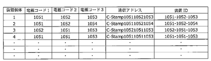
- the communication processing unit may further include a storage unit, and may store at least a unique device ID or a device ID unique in combination with the electrode code.
- the electrode code may be formed by at least one of the shape, size, and geometrical arrangement of the detected electrode, the size of the detected physical quantity, or a combination thereof.
- the touch panel may be a capacitive touch panel.
- the first information processing device recognizes a communication address including at least a part of the electrode code, or a communication address corresponding to at least a part of the electrode code, and connects to the communication processing unit. It may be.
- a first operation unit for controlling the communication processing unit is provided, and the first information processing device is provided with a communication address including at least a part of the electrode code or at least a part of the electrode code.
- a connection state with the communication processing unit may be established by recognizing a corresponding communication address and operating the first operation unit.
- the touch panel further includes a sensing unit that senses a state of touching or substantially touching the touch panel, wherein the first information processing apparatus includes a communication address including at least a part of the electrode code, or at least one of the electrode codes.
- the communication unit may be connected to the communication processing unit by recognizing a communication address corresponding to the unit and detecting a state where the touch panel is in contact with or substantially in contact with the touch panel.
- the sensing unit may detect a change in a physical quantity detected from the touch panel.
- the sensing unit may include one or more light detection sensors on a surface that contacts or substantially contacts the touch panel, and may detect light displayed on the touch panel.
- the position of the one or more optical sensors is recognized by at least one of the shape, size, geometrical arrangement, and detected physical quantity of the electrodes forming the electrode code, or a combination thereof.
- at least one of the color of light, the intensity of light, and the blinking time may be changed in a time series to obtain an optical code formed by the history. .
- the communication processing unit which is closest to the processing device may be connected to the communication processing unit.
- the communication processing unit may further include a GPS, and the first information processing device may recognize a position acquired by the GPS.
- the communication processing unit may be provided with a clock function to transmit time information or information that changes with time.
- the casing may be any one of a plate shape and a three-dimensional shape, and a film formed of a non-conductive material may be provided on a surface of a bottom portion of the casing.
- the conductive material is connected to a contact portion formed in a region on the surface of the housing, and is brought into contact with the electrode by contacting or holding the contact portion, whereby the electrode is electrically connected to the electrode and detected by the touch panel.
- the formed electrode code may be recognized.
- the conductive material is connected to contact portions formed in a region on the surface of the housing, and the contact portions are formed in a plurality of regions on the surface of the housing, and at least one of the plurality of regions By contacting or holding any of the regions, the electrodes connected to the respective conductive materials in the regions are electrically connected to each other, and a switchable electrode code formed by the electrodes detected by the touch panel is recognized. You may.
- a film made of a non-conductive material may be provided on the surface of the contact portion.
- At least a part of a conduction path between the electrode and the conductive material is made conductive or cut off, and an electrode code formed by the electrode detected by the panel is switched. It may further comprise one or more possible second operating parts.
- a conduction control unit capable of electrically conducting or interrupting at least a part of a conduction path between the electrode and the conductive material to switch an electrode code formed by an electrode detected on the panel. It may be further provided.
- an electrode code based on the history of the electrodes detected by the panel may be formed by changing the electrical conduction or cutoff in a time series.
- the electrode code may include a code for instructing the first information processing device to perform predetermined information processing.
- a device includes a communication processing unit provided in a housing of the device in which a plurality of electrodes are arranged on a bottom surface of the housing, and a touch panel that detects a change in a physical quantity and detects one or more positions. And a first information processing device connected to the touch panel, by bringing the bottom surface of the housing into contact or substantially contact with the touch panel, and forming an electrode code formed by a plurality of electrodes detected by a change in a physical quantity detected by the touch panel.
- An information communication method is characterized in that the first information processing apparatus recognizes and sets a connection state based on at least a part of the electrode code.
- connection based on at least a part of the electrode code may be performed by the first information processing apparatus including a communication address including at least a part of the electrode code or a communication address corresponding to at least a part of the electrode code. And an information communication method in which the communication processing unit and the first information processing apparatus are connected to each other.
- connection based on at least one part of the electrode code may be performed by the first information processing device by a communication address including at least one part of the electrode code or a communication corresponding to at least one part of the electrode code.
- an information communication method is characterized in that the communication processing unit detects a light from the touch panel, thereby connecting the communication processing unit and the first information processing device.
- a processing device connected to the first information processing device, and transmitting the fifth predetermined information from the first information processing device to the third information processing device, or from the third information processing device to the first information processing device; Transmitting the sixth predetermined information; or (D) transmitting the sixth predetermined information to the second information processing apparatus.
- the third information processing device is connected to the third information processing device by a predetermined method, and the seventh predetermined information is transmitted from the second information processing device to the third information processing device, or the third information processing device is Transmitting an eighth predetermined information to the second information processing apparatus; and / or transmitting an eighth predetermined information to the second information processing apparatus.
- a unique device ID or a unique device ID in combination with the electrode code is stored in the communication processing unit, and the device ID is stored in at least one of the first or third predetermined information. And an information communication method.
- the device ID that is unique in combination with the electrode code is unique when the first information processing device recognizes the electrode code that is different from the combination. Is determined as an erroneous recognition.
- At least one of the first to third information processing apparatuses has a first specific code for specifying the information processing apparatus and / or a second specific code set by operating software. Then, at least one of the second, fourth, fifth, sixth, seventh and eighth predetermined information transmitted from the information processing apparatus having the specific code includes the first or second specific information.
- An information communication method including any of the codes.
- the first information processing device recognizes a communication address including at least a part of the electrode code, or a communication address corresponding to at least a part of the electrode code, and recognizes one or more of the third or more third addresses.
- the third information processing device is characterized by an information communication method including the second information processing device.
- a right or wrong of at least one of the first to eighth predetermined information received by the device according to any one of claims 1 to 21 and the first to third information processing devices is determined by a predetermined value. And an information communication method.
- an information communication method is characterized in that at least one of the first to eighth predetermined information includes predetermined data and encrypted information obtained by encrypting the predetermined data.
- an information communication method is characterized in that the encrypted information is information obtained by encrypting encoded data obtained by encoding the predetermined data by an encoding unit by an encryption unit.
- the information processing device that has received the predetermined information, the encoded information obtained by decoding the encrypted information by a decoding unit, and the encoded information obtained by encoding the predetermined data by the encoding unit.
- the predetermined processing may be a connection state between the third information processing apparatus and the first or second information processing apparatus, or the communication processing unit and the first information processing apparatus and / or An information communication method including a process of disconnecting at least one of a connection state with a second information processing apparatus is characterized.
- the information processing method is characterized in that the communication processing unit has a clock function and the first and / or third predetermined information includes time information or information that changes with time.
- An information communication system comprising: a device according to the present invention; and a first information processing device connected to a touch panel that detects a change in a physical quantity and detects one or more positions.
- the first information processing device recognizes an electrode code formed by an electrode detected by the touch panel among the plurality of electrodes by contacting or substantially contacting a plurality of electrodes arranged on a bottom surface of the housing of the device.
- An information communication system is characterized in that a communication processing unit provided in a housing of the device and the first information processing device are connected based on at least a part of the electrode cord.
- the apparatus further includes a second and / or third information processing device, An information communication system, wherein information processing is performed by the information communication method according to any one of claims 26 to 38.
- the information processing system is characterized in that the first information processing device is a smartphone.
- a touch panel connected to the first information processing device which detects a change in physical quantity and detects one or more positions, includes a plurality of touch panels arranged on the bottom surface of the housing of the device according to the present invention.
- the first information processing device recognizes an electrode code formed by the electrode detected by the touch panel, by contacting or substantially contacting the electrode, based on at least a part of the electrode code,
- An information communication method according to the present invention is characterized by a program for connecting the first information processing device and a communication processing unit provided in a housing of the device.
- a program which further includes a second and / or third information processing device, and executes information processing by the information communication method according to the present invention.
- FIG. 2 is a schematic diagram illustrating an outer shape of the code generator according to the first embodiment.
- 3 is a diagram illustrating an example of a code generation device according to Embodiment 1.
- FIG. (A) is a diagram showing a conductive pattern printed on a conductive pattern printing sheet, and (B) is a diagram showing a shape when the conductive pattern printing sheet is attached to a lower housing.
- FIG. 3 is a circuit schematic diagram of the code generator according to the first embodiment.
- (A) schematically shows a first conductive pattern detected by the touch panel in a state where the code generator touches the touch panel by touching the human body contact electrode, and
- (B) shows a push button of the code generator.
- FIG. 9 is a schematic diagram illustrating an outer shape of a code generator according to a second embodiment.
- FIG. 9 is a diagram illustrating an example of a structure of a code generation device according to a second embodiment.
- FIG. 9 is a diagram illustrating an example of a structure of a code generation device according to a second embodiment. It is a figure which shows the electrode detection outline
- FIG. 13 is a schematic diagram illustrating an outer shape of a code generator according to a third embodiment.
- FIG. 14 is a circuit schematic diagram of a code generator according to a fourth embodiment.
- FIG. 14 is a schematic diagram illustrating an outer shape of a code generator according to a fourth embodiment.
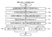
- FIG. 18 is a diagram illustrating a method of determining electrode detection coordinates (STEP 1) and (STEP 2) for pattern coding according to the fifth embodiment.
- FIG. 4 is a diagram illustrating a coordinate conversion method for pattern coding.
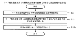
- FIG. 21 is a flowchart illustrating an example of a pattern encoding process according to the fifth embodiment.
- FIG. 16 is a schematic diagram illustrating an outer shape of a code generator according to a sixth embodiment.
- FIG. 14 is a schematic diagram illustrating a configuration of a code generation device according to a sixth embodiment.
- FIG. 15 is a schematic sectional view showing the structure of a code generator according to a sixth embodiment.
- FIG. 21 is a schematic diagram showing a form of a code generation device which is a modification of the sixth embodiment.
- FIG. 21 is a schematic diagram showing a form of a code generation device which is a modification of the sixth embodiment. It is a figure showing the code specification of the multicode stamp which can set up a plurality of stamp codes by a slide switch. It is a flowchart figure which shows the authentication system using an electronic stamp.
- 5 is an embodiment of a code generator equipped with a dot code reader.
- 5 is an embodiment of a code generator equipped with an optical code reader.
- 5 is an embodiment of a code generator equipped with an optical code reader. It is an example which shows the synchronization by an optical code reader. It is an example which shows the time series change of the synchronization by an optical code reader.
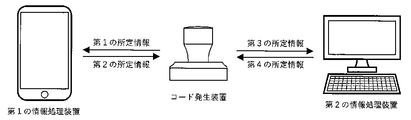
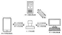
- FIG. 2 is a diagram illustrating a connection between a code generation device and an information processing device.
- FIG. 2 is a diagram illustrating a connection between a code generation device and an information processing device. It is the figure which illustrated the position where an electrode can be arrange
- (A) is a schematic side view showing an example of the appearance of the stamp-type code generator 120
- (B) is a schematic top view
- (C) is a schematic bottom view.
- FIG. 3 is a schematic cross-sectional view of a side surface of the code generator 120 cut in a vertical direction.
- (A) is a schematic side view showing an example of the appearance of the stamp-type code generator 120
- (B) is a schematic top view
- (C) is a schematic bottom view.
- (A) is a schematic diagram of the configuration of the code generator 121
- (B) is a diagram illustrating an example of a switch circuit of the conduction control unit.
- FIG. 3 is a schematic cross-sectional view of a side surface of a code generator 121 cut in a vertical direction.
- This is a stamp shape applicable as a code generator including a communication processing unit.
- This is a stamp shape applicable as a code generator including a communication processing unit.
- an electrode pattern composed of five electrodes is formed in five stages. This is an example in which an electrode pattern including five electrodes is formed in four stages. This is an example in which an electrode pattern composed of five electrodes is formed in three stages. This is an example in which an electrode pattern composed of five electrodes is formed in two stages. This is an example in which an electrode pattern composed of five electrodes is formed in five stages.
- FIG. 9 is a flowchart illustrating transmission and reception of information between a code generation device and an information processing device.
- 9 is a flowchart illustrating transmission and reception of information between a code generation device and an information processing device.
- 9 is a flowchart illustrating transmission and reception of information between a code generation device and an information processing device.
- 9 is a flowchart illustrating transmission of encryption information by a code generation device.
- 9 is a flowchart illustrating transmission of encryption information by a code generation device.
- 9 is a flowchart illustrating transmission of encryption information by a code generation device.
- FIG. 4 is a diagram illustrating transmission and reception of information between a code generation device and an information processing device.
- 5 is a flowchart illustrating transmission and reception of information between a code generation device and an information processing device.
- FIG. 4 is a diagram illustrating transmission and reception of information between a code generation device and an information processing device.
- FIG. 4 is a diagram illustrating transmission and reception of information between a code generation device and an information processing device.
- 9 is a flowchart illustrating transmission and reception of information between a code generation device and an information processing device.
- 9 is a flowchart illustrating transmission and reception of information between a code generation device and an information processing device.
- FIG. 4 is a diagram illustrating transmission and reception of information between a code generation device and an information processing device.
- 9 is a flowchart illustrating transmission and reception of information between a code generation device and an information processing device.
- FIG. 4 is a diagram illustrating transmission and reception of information between a code generation device and an information processing device.
- 9 is a flowchart illustrating transmission and reception of information between a code generation device and an information processing device.
- FIG. 4 is a diagram illustrating transmission and reception of information between a code generation device and an information processing device.
- 9 is a flowchart illustrating transmission and reception of information between a code generation device and an information processing device.
- FIG. 4 is a diagram illustrating transmission and reception of information between a code generation device and an information processing device.
- 9 is a flowchart illustrating transmission and reception of information between a code generation device and an information processing device.
- (A) shows an example of a schematic top view of a card-type code generator 120a
- (B) is a schematic side view
- C) is a schematic sectional view
- (D) is a schematic bottom view.
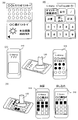
- E is a schematic configuration diagram. It is a figure showing the Example of the personal authentication service using the present invention.
- FIG. 2 is a diagram illustrating an information service using a print medium using the present invention. It is a figure showing the mail-order service by the print media which used this invention. It is a figure showing the entertainment service which used this invention. It is a figure showing the information transfer service using the present invention. It is a figure showing the dot code formation medium information link using the present invention.
- FIG. 34 is a schematic external view of a code generator according to a thirteenth embodiment.
- 138 is an example of a substrate pattern of a first substrate according to Embodiment 13.
- FIG. 39 is an explanatory diagram of the wiring connection method of the electrodes of the first substrate according to the thirteenth embodiment.
- FIG. 39 is a board pattern diagram of a second board of the thirteenth embodiment.
- FIG. 39 is an explanatory diagram of a wiring connection method between a first substrate and a second substrate according to the thirteenth embodiment.
- FIG. 21 is a cross-sectional view of a code generator according to a thirteenth embodiment and a connection state explanatory diagram.
- 129 is an explanatory diagram of Modification Example 1 of the code generation device of Embodiment 13. [FIG.
- FIG. 129 is an explanatory diagram of Modification Example 2 of the code generator of Embodiment 13.
- FIG. 129 is an explanatory diagram of Modification 3 of the code generator of Embodiment 13.
- FIG. 129 is an explanatory diagram of Modification Example 4 of the code generation device of Embodiment 13.
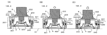
- FIG. 32 is a schematic external view and a cross-sectional view of a code generation device according to a fourteenth embodiment.
- FIG. 28 is an explanatory diagram of a switch operation of the code generator according to the fourteenth embodiment.
- FIG. 35 is a diagram schematically illustrating a drive mechanism of a code generator 125 according to a sixteenth embodiment.
- FIG. 35 is a diagram schematically illustrating a driving mechanism of a code generation device 126 according to a sixteenth embodiment.
- FIG. 21 is a schematic diagram showing a structure of a code generation device according to a seventeenth embodiment.
- FIG. 21 is a schematic diagram showing a structure of a code generation device according to a seventeenth embodiment.
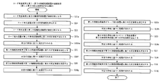
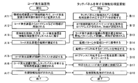
- 9 is a flowchart illustrating an overall image of information processing.
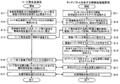
- 5 is a flowchart showing a process of connecting a code generator and a first information processing device.
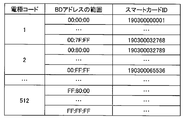
- 5 is a flowchart showing a process of connecting a code generator and a first information processing device. It is a table which illustrates mapping of an electrode code and BD address. It is a figure showing the example of application of a POS system.
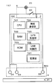
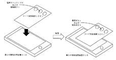
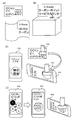
- FIG. 1 is a diagram illustrating an example of an external configuration of an information processing system according to an embodiment of the present invention.
- the information processing system shown in FIG. 1 includes a code generator 1 for generating a code, a code recognition device 3 for recognizing the code, and a server 4 for executing a predetermined process related to the code.
- the code recognition device 3 and the server 4 are connected via a predetermined network N such as the Internet.
- the code recognition device 3 is configured by an information processing device such as a smartphone having a touch panel 31 or a tablet.
- the touch panel 31 includes a display unit and a capacitance-type position input sensor stacked on the display surface of the display unit.
- the touch panel 31 displays an area SP (hereinafter, referred to as a “code detection area SP”) for detecting an electrode group indicating a pattern code output by the code generation device 1.
- the code recognition device 3 includes a detection unit and a recognition unit as functional blocks (not shown).
- the function block may be constituted by hardware alone, but in the present embodiment, it is assumed that the function block is constituted by software and hardware. That is, the detection unit and the recognition unit exert the following functions by cooperation of software and hardware.
- the detecting unit based on the detection result of the position input sensor, when one or more electrodes 5 connected to the human body with low impedance by the code generator 1 contact or approach the code detection area SP of the touch panel 31. A conductive pattern as arrangement information of one or more electrodes 5 is detected.
- the recognition unit recognizes the pattern code generated by the code generator of the code generator 1 based on the detected conductive pattern of the one or more electrodes.
- This pattern code is sent to the server as needed.
- the server executes various processes based on the pattern code.
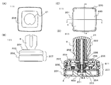
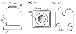
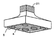
- FIG. 2 is a schematic diagram illustrating an outer shape of the code generator 111 according to the eleventh embodiment.
- 2A is a top view
- FIG. 2B is a side view
- FIG. 2C is a bottom view
- FIG. 2D is a cross-sectional view taken in a vertical direction.
- the code generator 111 has a shape similar to a square stamp
- the upper part of the housing 2 is a push button of the push button switch of the operation unit 6.
- the handle portion 222 is formed of a conductor so as to be able to be naturally touched while being held in the hand, and is used as the human body contact conductive material 21.
- a conductive pattern of 0.188 mm thick PET resin printed with conductive ink on the electrode 5 is printed.
- the sheet 400 is adhered with a double-sided adhesive tape having a thickness of 50 ⁇ m so that the position of the electrode 5 is not shifted and the strength is such that the sheet 400 can be easily peeled off.
- the thickness and the material of the conductive pattern printing sheet 400 are such that the electrode 5 is detected by the touch panel 31 when it comes into contact with the touch panel 31 through the base material of the sheet.
- the thickness and the material are not limited to the above and may be any thickness and material as long as durability enough to withstand the operation can be secured.
- a polypropylene resin sheet or a high-quality paper for photo printing coated with PP may be used.
- the bonding method is not limited to a double-sided tape, but may be a method of applying an adhesive, as long as the bonding surface can be easily peeled off without causing displacement of the bonding surface.
- the conductive ink used for printing the conductive pattern printing sheet 400 may be any ink having conductivity such as silver paste ink, silver salt ink, silver nano ink, carbon ink, and the like. From the viewpoint of the wiring time constant, the necessity of the flattening process of the ink layer, the disconnection of the wiring pattern, the failure rate such as the increase in resistance, etc., the minimum wiring width used in the conductive pattern is 0.8 mm or more in the carbon ink. 1.0 mm or less, and more preferably 0.6 mm or more and 1.0 mm or less as long as the defect rate such as disconnection of the wiring pattern and increase in resistance is within an allowable range.
- the thickness is preferably 0.2 mm or more and 0.3 mm or less. If the defect rate such as disconnection of the wiring pattern and the increase in resistance is within an allowable range, 0.1 mm or more and 0.2 mm or less. More preferred.
- the wiring method described later is adopted, and the minimum wiring width may be 0.8 mm or less. Is preferably about 100 ⁇ / mm, and may be 1 K ⁇ / mm or less.
- the thickness of the ink layer of the electrode 5 and the wiring to be formed by printing is preferably as small as possible, and is preferably 10 ⁇ m or less, and may be 20 ⁇ m or less which does not require a flattening process.
- a guide groove 205 shallower than the thickness of the conductive pattern printing sheet 400 including the double-sided adhesive tape is provided on the bottom surface 4 and the side surface of the lower housing 201.
- the design can be improved.
- the conductive pattern printing sheet 400 is in an exposed state, the electrodes of the touch panel 31 are provided for the purpose of protecting the sheet and the outer printing surface and preventing slippage (position shift) when the sheet is brought into contact with the touch panel 31.
- a protective sheet such as a thin silicon sheet of about 50 ⁇ m which does not hinder detection can be attached. When a protective sheet is attached, the thickness of the conductive pattern printing sheet 400 is preferably reduced to about 0.125 mm in consideration of the thickness of the protective sheet.
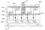
- a substrate 611 is fitted to the upper surface of the lower housing 201.
- board connection terminals 612 are arranged at equal intervals on the outer peripheral portion on the front surface side of the board 611, and as shown in FIG.
- a sheet connection terminal 404 is provided at a position corresponding to the marginal portion 403 provided at the tip of the side surface affixing portion 402 of 400.
- the board connection terminals 612 on the surface of the board 611 are formed by folding the marginal portion 403 of the conductive pattern printing sheet 400 affixed to the lower housing 201 onto the board 611 and screwing the board sheet presser 202 from above.
- the conductive pattern can be electrically connected to the conductive pattern connection terminal 404 provided on the folded portion 403 of the conductive pattern printing sheet 400 by pressing.
- a conductive adhesive or a conductive double-sided tape is applied between the connection terminals. By applying or attaching, conduction between the connection terminals can be ensured.
- the connection resistance between the connection terminals may be lower than about several tens of K ⁇ .
- the substrate sheet presser 202 includes a flat fixing portion that can simultaneously fix the outer periphery on the surface of the lower housing 201 to the substrate 611 and the conductive pattern printing sheet 400, and an outer frame portion that covers the side surface of the lower housing 201. Is provided.
- the outer frame portion while protecting the side surface portion of the conductive pattern printing sheet 400, it is formed into a shape that covers almost all the side surfaces of the code generator 111, and the outer surface of the outer frame portion is colored or patterned.
- the design of the code generator 111 can be improved.
- the board sheet presser 202 can be a simple flat plate without an outer frame portion.
- the substrate 611 has openings at four locations on the inner portion corresponding to the vertices of the rectangle, and is positioned with the lower housing 201 by inserting a substantially columnar support 206 projecting from the lower housing 201. You.
- the substrate 611 is also opened at the center of the substrate, the lower movable contact portion 251 is slidably inserted from the back surface to the front surface, and the upper movable contact portion 252 provided on the upper surface of the substrate 611 and the substrate 611 are connected. It is fixed as if sandwiched.
- a short wiring pattern is provided between the substrate connection terminal 612 provided on the outer peripheral portion of the surface of the substrate 611 and the upper fixed contact 613 provided around the surface of the central opening.
- a lower fixed contact 614 is provided around the back surface of the central opening of the substrate 611, and the shortest distance between the outer peripheral portion of the front surface via a thin wiring pattern and a through hole. It is connected to the board connection terminal 612.
- connection specifications from the board connection terminal 612 to the fixed contacts 613 and 614 in the central opening, (a) one in which the lower fixed contact 614 is provided only on the back surface, and (b) that in the front surface of the board 611. Only the upper fixed contact 613 is provided, and (c) the fixed contacts 613 and 614 are provided on both the front and back surfaces.
- At least one set is provided on each side of the substrate 611, and the total of each side is (a) and (b): 5 sets or 5 or more sets, and (c) is 4 sets. All you need is a pair. This is because the number of simultaneously detectable multi-touches set on the touch panel 31 of the smartphone such as the iPhone (registered trademark) which is the code recognition device 1 and the number of simultaneously detectable multi-touches are set between the electrode 5 of the conductive pattern printing sheet 400 and the board connection terminal 612 This is to ensure ease of wiring.
- the total number of sets of connection specifications required for each side of the board is (a) and (b), the number of multi-touches. Or, more than that, (c) is the number of multi-touches-1.
- connection specifications are used in accordance with the electrode detection specification of the conductive pattern to be created, (a) is used for an electrode detected on the touch panel 31 only when the second conductive pattern is used, and (b) is used for the first conductive pattern. It is used for an electrode detected on the touch panel 31 only in the case of a conductive pattern, and (c) is used for an electrode detected in both the first and second conductive patterns.
- the lower movable contact portion 251 has a structure in which a flange portion 253 is provided below a columnar member having a substantially rectangular shape in a plan view, and is entirely conductive.
- a contact interval between a portion where the lower fixed contact 614 of the substrate 611 contacts the lower movable contact 251 is located at a position facing the lower fixed contact 614 provided at the center opening of the back surface of the substrate 611 of the flange 253.
- a movable contact 254 made of elastic conductive rubber is provided in order to absorb the variation of the contact and make contact between all the contacts.
- the movable contact 254 is not limited to the conductive rubber, but may be a leaf spring contact or the like as long as it has elasticity, can absorb variations in contact intervals, and can conduct all contacts.
- the upper movable contact portion 252 has a structure in which a step portion 255 is provided on a columnar body having a substantially rectangular shape in a plan view, a concave portion is provided at the center of the column, and the lower movable contact portion 251 is inserted and fitted. Having. The position of the step portion 255 facing the upper fixed contact 613 provided at the center opening of the surface of the substrate 611 absorbs the variation in the contact interval of the portion where the upper fixed contact 613 on the substrate 611 contacts the upper movable contact portion 252.
- a movable contact 256 made of elastic conductive rubber is provided to make contact between all the contacts. Further, the movable contact 256 is not limited to the conductive rubber, similarly to the lower movable contact portion 251.
- the upper movable contact portion 252 has a latch structure on the upper portion, and is fitted and fixed to the upper housing 203.
- the upper housing 203 is provided with a cylindrical opening through which the support 206 is slidably inserted at a position corresponding to the support 206 projecting from the lower housing 201.
- At the bottom of the cylindrical opening there is a step where the diameter of the opening is reduced, and the spring is inserted into the support 206 and sandwiched between the lower housing 201 and the upper housing 203.
- the flanged screw is fixed to the support 206 through which the.
- the upper housing 203 and the lower housing 201 are slidably fixed, and a contact driving mechanism for the conductive pattern switching push button switch of the code recognition device 111 is formed.
- the lower fixed contact 614 and the movable contact 254, and the upper fixed contact 613 and the movable contact 256 are provided with appropriate intervals so that both contacts do not contact at the same time during the switching operation. It has become. This is to prevent the number of simultaneously detectable multi-touches set on the touch panel 31 of the smartphone such as iPhone (registered trademark) from being restricted.
- the structure from the lower housing 201 to the upper housing 203 is the main body 207.
- a holding portion 204 is attached to the upper housing 203 in a removable structure.
- the holding portion 204 includes a non-conductive lid portion that covers the upper housing 203 and enhances design, and a conductive handle portion 222 corresponding to a handle of the stamp.
- the handle 222 contacts and conducts with the upper movable contact 252.
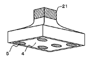
- FIG. 4 (A) shows a conductive pattern diagram printed on the conductive pattern printing sheet 400
- FIG. 4 (B) shows a shape when the conductive pattern printing sheet 400 is attached to the lower housing 201.
- the conductive pattern is printed with a conductive ink on a surface which becomes inside in a state where the conductive pattern printing sheet 400 is attached to the lower housing 201.
- the conductive pattern has the shortest distance between the circular electrode 5 having a diameter of 8 mm provided on the bottom surface 4 and the sheet connection terminal 404 provided on the folding portion 403, which has the minimum printable line width for each electrode. Connected in a print pattern as shown.
- the electrode 511 detected by the touch panel 31 with the first conductive pattern 81 is connected to the sheet connection terminal 404 to which the symbol (a) is added, and the electrode 512 detected by the touch panel 31 with the second conductive pattern 82 is , (B) are connected to the sheet connection terminal 404 and the electrodes 513 detected by the touch panel 31 on both the first and second conductive patterns 81 and 82 are provided with the code (c).
- Sheet connection terminal 404 Sheet connection terminal 404.
- the electrode 5 arranged at the center of the bottom surface 4 is connected to the original wiring connected to the sheet connection terminal 404 through the center point of the electrode 5 for connection.
- the wiring is drawn with a length about the radius of the electrode 5.
- the touch panel 31 detects the wiring part in addition to the electrodes due to the parasitic capacitance generated between the wiring and the touch panel when placed on the touch panel 31, and the detection coordinates of the electrodes are shifted in the wiring direction. Occurs. Therefore, when the wiring printed on the area of the bottom surface 4 is a long electrode, the wiring is extended in the direction opposite to the original wiring as shown in FIG. Is also generated, and the shift amount of the detection coordinates of the electrode can be reduced. If the wiring in the area of the bottom surface 4 is a short electrode, the extension wiring is unnecessary.
- Table 1 shows that five electrodes having a diameter of 8 mm were formed with carbon ink on the inner surface of a PET resin sheet having a thickness of 0.188 mm at a 7 ⁇ 7 electrode arrangement grid grid spacing of 7 mm. This is a comparison of the result of evaluating the displacement of the detection coordinates when the connected evaluation sample was detected 20 times on the touch panel of the smartphone (iPhone 6) with or without the extension wiring.
- the sample having the extension wiring is provided with the extension wiring of 0.8 mm in width and 4 mm in the direction 180 ° opposite to the original wiring.
- the detection coordinates on the touch panel are determined by using the lower left and upper right electrodes 511 as reference electrodes in the conductive pattern of FIG. was converted to the arrangement coordinates with a grid interval of 7 mm, and the other three electrodes (electrodes 2 to 4 in Table 4) were evaluated based on what percentage of the grid interval deviated from the arranged grid. It was confirmed that the shift amount can be reduced by 10% on average with the wiring.
- the wiring between the electrodes 5 for forming the conductive pattern was detected with the parasitic capacitance between the touch panel and the wiring with respect to the touch panel 31 when the wiring width was 0.8 mm.
- the wiring width between the electrodes 5 is preferably 0.8 mm or less, more preferably 0.2 mm or less, within the range of the allowable wiring width in which the conductive ink can be printed (wiring resistance does not increase).
- FIG. 5 is a schematic circuit diagram of the code generator 111.
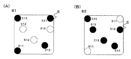
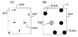
- FIG. 6A schematically shows a first conductive pattern 81 detected by the touch panel 31 in a state where the code generation device 111 touches the human body contact electrode 21 and is in contact with the touch panel 31 (STEP 1).
- 6 (B) schematically shows the second conductive pattern 82 detected by the touch panel 31 in a state where the push button of the code generation device 111 is pressed (STEP 2) from (STEP 1).
- the code generator 111 selectively connects the electrodes 5 and the wirings formed by printing the conductive pattern printing sheet 400 with the conductive ink to the sheet connection terminals 404 and the substrate connection terminals 612 of the substrate 611.
- the first conductive pattern 81 and the second conductive pattern 82 can be set to be changeable only by changing the print pattern of the conductive pattern print sheet 400 by connecting (a), (b), and (c). It is.
- the first conductive pattern 81 is formed by connecting the sheet connection terminals 404 connected from the electrodes 5 (511, 513) of the conductive pattern printing sheet 400 to the substrate connection terminals 612 (a) and (c) of the substrate 611. I do.
- the second conductive pattern 82 is formed by connecting the sheet connection terminal 404 connected from the electrode 5 (512, 513) of the conductive pattern printing sheet 400 to the substrate connection terminal 612 (b) and (c) of the substrate 611. I do.
- the first conductive pattern 81 is three or more so that the orientation of the first conductive pattern 81 placed on the touch panel 31 of the code generator 111 can be specified, and the arrangement of the electrodes 5 is not rotationally symmetric. It is preferable to set the number to five or less from the restriction on the number of multi-touches.
- the orientation of the contacted code generator 111 on the touch panel 31 is specified from the code decoding processing result of the first conductive pattern 81.
- the second conductive pattern 82 can perform a code decoding process using the information of the direction, so that a pattern in which the arrangement of the electrodes 5 is rotationally symmetric can also be used as the conductive pattern. Therefore, the number of codes of the second conductive pattern 82 can be dramatically increased.
- the number of codes is equal to that of the first conductive pattern 81.
- the multiplication of the second conductive patterns 82 results in a dramatic increase in the number of codes that can be set in the code generator 111.
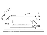
- FIG. 7 is a schematic diagram illustrating an outer shape of the code generator 112 according to the twelfth embodiment.
- 7A is a top view
- FIG. 7B is a side view
- FIG. 7C is a bottom view
- FIG. 7D is a cross-sectional view taken in the vertical direction.
- the code generator 112 differs from the first embodiment only in the structure of the holding unit 204a, and the main body 207 is the same as the code generator 111 of the first embodiment. And the same parts.
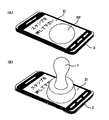
- the code generation device 111 is a stamp type, and holds the handle portion 222 by hand, touches the human body contact electrode 21, contacts the touch panel 31 such as a smartphone as the code recognition device 3, and presses the conductive member.
- the touch panel 31 detects a conductive pattern formed on the pattern printing sheet 400, and further switches the conductive pattern with a push button switch to generate a pattern code in time series.
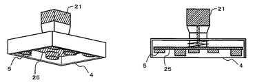
- the code generator 112 is used in a state where the main body 207 is attached to the flat holding portion 204a with the bottom surface 4 facing up. As shown in FIG. 7A, mounting holes 208 are provided at four corners of the flat holding portion 204a, and the mounting portion can be fixed to a wall or the like with the mounting holes 208 and screws. As shown in FIG. 8, the touch panel 31 is pressed against the bottom surface 4 of the code generation device 112 while holding the smartphone or the like as the code recognition device 3 by hand.
- the code generator 112 is installed on a wall, a desk, or the like near an exhibition display of a museum, and a visitor contacts the touch panel 31 such as a smartphone with the code generator 112 to obtain information on an exhibit.
- the code generator 112 is installed on the desk in the railway station yard, and the passenger can touch the touch panel 31 such as a smartphone to the code generator 112 to obtain stamp rally points. It is.
- the touch panel 31 it is necessary for the touch panel 31 to detect the conductive pattern formed on the conductive pattern print sheet 400 without the finger or the hand touching the human body contact electrode 21 and without conducting to the human body. (Human body non-conductivity detection)
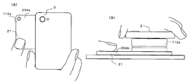
- FIG. 9A shows a comparison between the mounting structure of the holding unit 204 of the code generator 111 and the main body 207
- FIG. 9B shows a comparison of the mounting structure of the holding unit 204a and the main body 207 of the code generator 112.
- the upper surface of the upper housing 203 of the main body 207 is provided with a fitting groove 210 in which a part of the opening on the upper surface side is narrowed.
- a thick cylindrical projection 209 is provided.
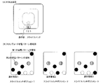
- FIGS. 10A and 10B schematically show the operation of detecting the electrode 5 of the general capacitive touch panel 31.
- FIG. (A) puts the code generator 111 on the touch panel 31 and performs a detection operation (a human body conduction detection method) in a state where a person touches it.
- a capacitance type touch panel 31 has a size of about 4 mm to 6 mm inside the touch panel 31 in order to detect the presence or absence of a finger touch on the surface of the touch panel and the touch position.
- a large number of TXn and RXn are arranged in a mesh so as to intersect vertically at intervals, and a capacitance Cm for detecting a touch is provided at the intersection of TXn and RXn.
- a capacitance is formed between Tap and TXn and between Tap and RXn, and the combined capacitance Cm 'between TXn and RXn is smaller than Cm.
- a voltage amplitude (AC signal) of about several hundred KHz is sequentially applied to a large number of TXn, and a current In flowing to the RXn side is measured for a large number of RXn, and at the intersection of the corresponding TXn and RXn being Tapped.
- the change in the capacitance of Cm ′ is measured by the change in the current value In, and the position (coordinate) of the Tap on the touch panel 31 is specified.
- the code generator 111 is placed on the touch panel 31 and the electrode 5 having a diameter of about 8 mm printed on the conductive pattern printing sheet 400 is tapped at any position on the touch panel 31. Then, the capacitance Cm ′ is changed by the electrode 5.
- the capacitance Cm ′ is changed by the electrode 5.
- Tap1 in FIG. 10A only one electrode 5 separated from the human body by a push button switch (not shown) built in the code generator 111 has a small change amount of Cm ′, and the current I1 Since the change is small, it does not reach the determination threshold value for the coordinate detection of the touch panel 31.
- the human body contact electrode 21 has a coupling capacitance Cp2 with the human body, and the voltage amplitude (AC signal) of TX2 is the coupling capacitance.
- a minute current is also applied to the human body via Cp2. For this reason, the amount of change in the current I2 of the RX2 becomes large, and exceeds the determination threshold value for the coordinate detection of the touch panel 31, and the position of the electrode 5 is detected.
- the electrodes 5 printed on the conductive pattern printing sheet 400 used in the code generator 112 must be transmitted via a substrate 611 (not shown) and a push button switch.
- the plurality of electrodes 5 are connected to each other.
- the electrodes 5 of Tap1 to Tap4 are connected to form a conductive pattern.
- an additional capacitance Cp2 'added to a conductive sheet 211 and a substrate 611 described later is provided at a common node to which the electrode 5 is connected.
- each electrode of the other Tap1, Tap3, and Tap4 via the common node. 5 has a coupling capacitance with TXn and RXn, and the voltage amplitude (AC signal) of TX2 causes a small current In to flow through RXn via the respective coupling capacitance. Further, the additional capacitance Cp2 'also becomes a coupling capacitance, and a small current flows to the ground.
- AC signal voltage amplitude
- the amount of change in the current I2 of the RX2 becomes large and exceeds the determination threshold value for the coordinate detection of the touch panel 31, and the position of the electrode 5 is detected.
- the touch panel 31 sequentially switches between TXn and RXn, and a certain position of another electrode 5 is reached, a small current is similarly applied to the coupling capacitance of the electrode 5 located outside the target TXn and RXn. Therefore, it is possible to make the touch panel 31 detect the positions of all the electrodes 5 connected to the common node.
- the electrodes 5 are all arranged on different TXn and RXn, the actual conductive patterns of the touch panel 31 and the code generator 112 are two-dimensional (planar).
- the plurality of electrodes 5 are arranged on a common TXn or a common RXn. At this time, the total effective capacitance may be reduced as compared with the case where all the electrodes 5 are arranged on different TXn and RXn.
- the capacitance CfR between the electrode and the RXn of the two electrodes 5 is equal to the combined capacitance of the series-connected capacitors.
- the terminal on both sides has the same configuration as that connected to the same RXn node, and the capacitance becomes invisible to RXn effectively.
- the electrode arrangement position of the conductive pattern on the touch panel 31 and the electrode detection performance depend on each other. Normally, the TXn and RXn on the touch panel 31 are arranged vertically and horizontally on the square touch panel surface. Therefore, when a plurality of conductive pattern electrodes 5 are arranged vertically or horizontally on the touch panel surface, the electrodes are detected. It becomes spicy.
- both the conductive patterns 81 and 82 be conductive patterns using a plurality of electrodes 5, within the limit of the number of multi-touches of the code recognition device 3. In this case, the more stable the detection, the more electrodes 5 are used.
- a conductive sheet 211 for adding capacitance is provided with an upper movable electrode portion 252 and a conductive region of the conductive sheet. Affixed for connection (conduction). Further, the capacitance-adding conductive sheet 211 may be attached to the upper surface of the flat holding portion 204a instead of the upper surface of the upper housing 203.
- the conductive sheet 211 for adding capacitance may be a sheet such as a copper film having conductivity as a whole, or a sheet having a conductive pattern formed by printing with a conductive ink similarly to the conductive pattern printing sheet 400. .
- the wiring can be provided in a loop shape of approximately 12.5 cm and resonated with a WiFi radio wave having a frequency of 2.5 GHz to assist the electrode detection of the touch panel 31. Further, the conductive sheet 211 may be omitted.
- a conductive material to be connected to the movable electrode portion is provided in an empty area of a pattern having no wiring or contact on the front and rear surfaces of the substrate 611 shown in FIGS.
- a pattern may be formed to serve as an additional capacitor.
- a conductive pattern may be formed as a wiring in a region of the conductive pattern printing sheet 400 shown in FIG. 4A where there is no electrode and no wiring, and may be connected to the movable electrode portion via the substrate 611 to provide an additional capacitance.
- FIG. 11 is a schematic diagram illustrating an outer shape of the code generator 112a according to the third embodiment.
- FIG. 11A is a top view in a use state
- FIG. 11B is a side view in a use state.
- the code generator 112a is obtained by changing the holding unit 204a of the code generator 112 for detecting the non-conduction of the human body to the human body conduction detection. There is no change from the code generator 112 except for the holding unit 204a and the method of use.
- the holding portion 204b of the code generator 112a is made larger in one direction than the plane size of the main body 207 so that the smartphone, which is the code recognition device 3, is in contact with the bottom surface 4.
- the size is such that the holding portion 204b can be easily touched.
- the holding portion 204b is made of a conductive resin, or a resin surface plated with metal, made of metal, and has conductivity.
- the holding portion 204b fits and rotates a fitting groove 210 provided in the upper housing 203 of the main body portion 207 and a fitting protrusion 209 on a mounting surface of the holding portion 204b, similarly to the holding portion 204a.
- the holding portion 204b and the main body 207 are fixed, and when the main body 207 is fixed, the upper movable contact portion 252 exposed on the upper housing 203 is pressed and electrically connected.
- the holding portion 204b becomes the human body contact electrode 21, and the code generator of the human body continuity detection system can be obtained.
- the smartphone 204 as the code recognition device 3 is held with the right hand, and the 204b is spread leftward on the premise that the holding unit 204b is touched with the left hand, but the 204b may be widened as a whole.
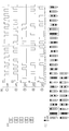
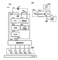
- FIGS. 12A and 12B are circuit schematic diagrams of a code generator 115 according to the fourth embodiment.
- FIG. 12A shows a case where an ID switching electrode 514 is provided on a first conductive pattern 81
- FIG. FIG. 9 is a circuit schematic diagram in a case where an ID switching electrode 514 is provided in the first embodiment.
- the specification of the code generator 115 is different from the specification of the code generator 111 in that an ID changeover switch 95 as an operation unit is added, and a plurality of conductive patterns are provided on one of the first and second conductive patterns 81 and 82. The difference is that it is possible.
- an SP3T (one-circuit, three-contact) slide switch 95 is provided between the fixed contact 614 on the back surface of the substrate 611b and the electrode 5, and an electrode 514 is provided for each contact terminal of the switch. Connecting.
- an SP3T (one-circuit, three-contact) slide switch 95 is provided between the fixed contact 614 on the back surface of the substrate 611b and the electrode 5, and an electrode 514 is provided for each contact terminal of the switch. Connecting.
- an SP3T type (one circuit, three contacts) slide switch 95 is provided between the fixed contact 613 on the surface of the substrate 611c and the electrode 5, and an electrode 515 is provided for each contact terminal of the switch. Connecting. Accordingly, it is possible to switch which electrode 515 is conducted to the human body contact electrode 21 by the second conductive pattern 82 depending on the position of the slide switch 95, thereby generating three different types of second conductive patterns 82. Can be done.
- FIG. 13 is a schematic view showing the outer shape of the code generator 115.
- FIG. 13A is a top view
- FIG. 13B is a side view
- FIG. 13C is a cross-sectional view taken in the vertical direction.
- the code generator 115 has a shape similar to a square stamp similarly to the code generator 111 shown in the first embodiment, and the upper part of the housing 2 has the operation unit 6. Since the push button switch is a push button, the housing 2 is held in hand and is in contact with the touch panel 31, and when pressed, two patterns of a first conductive pattern 81 and a second conductive pattern 82 are formed. Since codes can be sequentially generated and the ID changeover switch 95 is provided, it is possible to provide a plurality of either one of the first conductive pattern 81 or the second conductive pattern 82. It is a specification.
- openings 231 and 241 are provided in the upper housing 203 and the holding unit 204, respectively, and the switch 951 for operating the cord can be switched from the opening 241. It protrudes to the extent.
- a mark 242 corresponding to the code of the conductive pattern is provided at a portion corresponding to each switching position of the slide switch on a side of the opening 241 on the upper surface of the housing 2 along the direction in which the code switching switch operating portion 951 slides. Is provided.
- the mark 242 is formed in such a shape that a mark “ ⁇ ” indicating a number and a position is carved shallowly on the upper surface of the holding portion 204.
- the mark 242 is not limited to this, and may be provided in a convex shape, or may be formed by printing or attaching a seal. Further, the mark 242 is not limited to a numeral, and may be a graphic or the like corresponding to a use situation.
- the opening 241 provided in the holding unit 204 extends in a substantially arc shape counterclockwise in the center direction of the holding unit 204 in addition to a rectangular opening along the sliding direction of the cord switching switch operation unit 951. This is because, similarly to the code generator 111 of the first embodiment, the code generator 115 is provided with a mechanism for rotating and holding the holding unit 204 and the upper housing 203 shown in FIG. is there.
- the opening 231 provided in the upper housing 203 is large enough that the body portion of the slide switch 95 does not contact the upper housing 203 when the handle 222 is pressed to switch the push button switch of the operation unit 6. It is open at the end.
- the two types of circuit specifications corresponding to FIGS. 12A and 12B can be changed only by exchanging the boards 611b and 611c which differ only in the pattern wiring. Can be used commonly in the specifications.
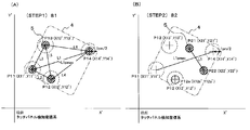
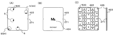
- FIG. 14 is an explanatory diagram of a method of determining (STEP1) and (STEP2) of the electrode detection coordinates for pattern coding, where (A) is the state of (STEP1) and (B) is the state of (STEP2). .
- FIGS. 15A and 15B are diagrams showing a coordinate conversion method for pattern coding.
- FIG. 15A is a diagram showing a detection state of the detection coordinate system of the touch panel 31.
- FIG. (C) is a state in which the detection state of (STEP 2) is converted to the electrode arrangement grid coordinate system of the code generator 1.
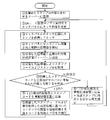
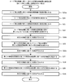
- FIG. 16 is a flowchart illustrating an example of the pattern encoding process of the code generator 1 having the operation unit 6 and capable of switching between the first conductive pattern 81 and the second conductive pattern 82.
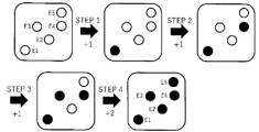
- the code generator 1 capable of switching the conductive pattern, for example, by pressing the push button switch 60 which is the operation unit 6, the state before the press (STEP 1) and the state after the press (STEP 2) By switching between connecting and disconnecting the plurality of electrodes 5 provided as the first conductive pattern 81 and the second conductive pattern 82 to and from the human body conductive material 21, two types of codes can be generated. It is a specification that can be done.
- FIG. 15B shows an example of electrode arrangement of the first conductive pattern 81
- FIG. 15C shows an example of electrode arrangement of the second conductive pattern.
- the electrodes 5 are provided with an X, Y electrode arrangement grid coordinate system in the area of the bottom surface 4 of the code generator 1 in contact with the touch panel 31, and are arranged at integer coordinate points thereof. Thereby, the arrangement interval of each electrode 5 can be easily calculated from the unit grid interval of the grid coordinate system.
- the unit grid interval is set based on the size of the touch panel 31 that is assumed to be used, the coordinate detection position accuracy of the touch panel, the size of the bottom surface 4 of the code generator 1, the size of the electrode 5, and the like.
- the coordinate system is such that the area of the bottom surface 4 is divided into 0 to 6 for both X and Y.
- the arrangement of the electrodes 5 in each conductive pattern cannot be arranged at all the integer coordinate points, and the interval between the electrodes 5 and the restriction on the arrangement position are limited by the size of the electrode 5 and a plurality of electrodes as the conductive pattern.
- the determination is made in consideration of the influence on the detection coordinates of the touch panel 31 when 5 is arranged at a close coordinate position. For example, the minimum value of the electrode interval needs to be equal to or longer than the distance at which the two electrodes 5 are not detected as one electrode on the touch panel 31.
- a plurality of electrodes are arranged in parallel with the outer frame of the touch panel, a plurality of electrodes 5 Are arranged side by side, which may affect the detection of the touch panel 31. Therefore, the number of electrodes 5 arranged on the same line in the conductive pattern may be limited.
- the first conductive pattern 81 at least three electrodes 5 need to be detected so that the direction in which the code generator 1 is placed on the touch panel 31 can be specified.
- a maximum of five electrodes is preferable. Therefore, in the present embodiment, four electrodes 5 are provided in the first conductive pattern 81.
- the number of multi-touch is not limited or five or more tablets, or a case where a dedicated business device is used as the code recognition device 3
- the minimum number and the maximum number of electrodes are not limited to the above numbers.
- the first conductive pattern 81 it is preferable to provide a reference electrode in order to facilitate code decoding.
- all the first conductive patterns 81 are provided with two electrodes in the grid coordinate system (0, 0) and (6, 6) where the distance between the electrodes is the longest as a reference electrode.
- the length Lmax between the reference electrodes and the angle ⁇ 1 between the line connecting the reference electrodes and the X axis of the grid coordinate system can be used for code decoding.
- the reference electrode position is not limited to the coordinates of the present embodiment, but may be any one that can specify the angle between the reference electrode distance, the line connecting the reference electrodes, and the X axis of the grid coordinate system. Good.
- the reference electrodes at two points (0, 0) and (5, 6), and to make the code decoding processing algorithm correspond to the reference electrode position. Accordingly, a large number of conductive patterns of different code systems can be set. For example, a code system using two points (0,0) and (6,6) as reference electrodes in the embodiment, a code system using two points (0,0) and (5,6) as reference points, Furthermore, if a conductive pattern and a code decoding processing algorithm corresponding to each of a plurality of code systems are prepared and stored, such as a code system using another two points as reference points, the main body of the code generator 1 can be prepared. More code can be issued as a whole system without any changes.
- the information of the electrode arrangement coordinates of both the first conductive pattern 81 in (STEP 1) and the second conductive pattern 82 in (STEP 2) is stored in a code because of the feature of the switchable code generator 1. Since it can be used for decoding, a reference electrode is not required. For this reason, the second conductive pattern 82 can freely arrange the electrodes 5 at the arrangement coordinates according to only the restrictions on the intervals and arrangement of the electrodes 5.
- the number of arranged electrodes is one or more, and the electrodes can be freely arranged within the range of the number of constraints of the number of multi-touches. Therefore, more conductive patterns can be set as the second conductive patterns 82. In the present embodiment, one to four electrodes are arranged on the second conductive pattern 82.
- the electrode 5 of the second conductive pattern 82 is arranged at the same coordinate as the arrangement coordinate of the electrode 5 arranged on the first conductive pattern 81 due to the feature of the switchable code generator 1. It is also possible.
- the conductive pattern printing sheet 400 when the electrodes 5 of the first and second conductive patterns 81 and 82 are arranged at the same coordinates, the conductive pattern printing sheet The number of electrodes printed on 400 is smaller than the number of electrodes used in (STEP 1) and (STEP 2), and the arrangement of electrodes 5 of two types of conductive patterns becomes easy, and a large number of conductive patterns are set. Will be possible.
- a reference electrode is provided on the first conductive pattern 81, and the number of the electrodes 5 is three or more, so that the direction in which the first conductive pattern 81 is placed on the touch panel 31 can be specified.
- the reference electrode is not provided on the second conductive pattern 82, the reference electrode is provided on the second conductive pattern 82 and the number of the electrodes 5 is three or more. It is also possible to specify the orientation of the first conductive pattern 81 provided on the first conductive pattern 81 without providing a reference electrode. If the specification of the latter configuration is separately provided, more codes can be issued as a whole system without changing the main body of the code generator 1.
- a pair of reference electrodes can be provided by combining both patterns of the first conductive pattern 81 and the second conductive pattern 82. For example, by providing the reference electrode at the position (0, 0) on the first conductive pattern 81 and providing the reference electrode at the position (6, 6) on the second conductive pattern 82, the longest distance between the electrodes can be obtained. A distance is formed between the electrodes 5 of the first and second conductive patterns 81 and 82, and the touch panel is formed by using the electrodes 5 other than the reference electrode of one of the first and second conductive patterns 81 and 82. It is also possible to make it possible to specify the orientation placed on 31. As a result, the number of electrodes that can be freely arranged on both the first and second conductive patterns 81 and 82 increases, so that more conductive patterns can be provided and more codes can be issued as a whole system.
- the coordinates of the electrode arrangement coordinates of the first conductive pattern 81 and the second conductive pattern 82 created based on these specifications are standardized as standardized coordinate pattern codes for (STEP1) and (STEP2). Create a coordinate pattern code table.
- a first conductive pattern 81 of (STEP 1) and a second conductive pattern 82 of (STEP 2) are provided. It is a specification that two kinds of codes can be generated by switching between connecting and disconnecting a plurality of electrodes 5 respectively to and from the human body contact conductive material 21.
- the electrodes 5 that are not necessary for the respective conductive patterns 81, 82 in the respective conductive patterns 81, 82 are disposed on the bottom surface 4 of the code generating device 1.
- the touch position detection algorithm of the touch panel 31 of the smartphone 3 in order to continuously recognize the touch of the finger as the same touch, control for lowering the threshold value of the detection sensitivity of the touch position once detected (detection threshold value) is performed.
- the first conductive pattern 81 in (STEP 1) is connected to the human body contact conductive material 21.
- the detected electrode 5 may continue to be detected by the touch panel 31 even though it is cut off from the human body conductive material 21 by the second conductive pattern 82 in (STEP 2). A problem arises in that the pattern 82 cannot correctly recognize the code.
- the electrode arrangement specification of the conductive pattern according to the present embodiment complies with the following four conditions. (1) Four electrodes 5 including two reference electrodes are used in the first conductive pattern 81. (2) In the second conductive pattern 82, one to four electrodes 5 are used. Further, (3) in the electrode arrangement of the second conductive pattern 82, the electrode is not arranged at the electrode arrangement position of the first conductive pattern 81. (4) The distance between the electrodes of the second conductive pattern 82 is smaller than the distance between the reference electrodes. The length is set to be smaller than the length Lmax.
- FIG. 16A shows a pre-processing flow of detection coordinate determination
- FIGS. 14A and 14B show examples of electrode detection states in (STEP 1) and (STEP 2) in the touch panel coordinate system.
- the operation proceeds to (STEP 1), and the touch panel 31 detects the coordinates of four points in the state of S1. Based on the detected coordinates, all the distances between two of the four points of the code recognition device are calculated to obtain the longest inter-electrode distance L1pmax, and the electrode coordinates of the four points (STEP 1) before being pressed are as follows: P11 to P14 are stored.
- FIG. 14A shows an example in which the touch panel detects four points P11 to P14 in (STEP 1).
- the distance between the detection coordinates P11 and P14 is L1pmax at the longest, and each detection coordinate position is indicated by a broken line.
- the inside of the concentric circle having the radius L1pm / 2 indicates the detection coordinate allowable error range.
- the touch panel When the touch panel further detects the coordinates of four new points from the state of S2, the state becomes S3, and all the distances between two of the four points are calculated to obtain the longest inter-electrode distance L1pmax ′. If the value is within the range of ⁇ L1 pm / 2 with respect to the stored L1pmax, the electrode coordinates P11 to P14 of the four points in (STEP 1) are updated, and S2 is performed again.
- the state becomes S5
- the coordinate values of the sensing electrode coordinates P21 to P2n at that time are compared with the stored coordinate information from P11 to P14, and P11 to P14 are stored. Only the coordinates outside the range of the concentric circle L1pm / 2 of the coordinates are left, and the remaining number m of the detection electrodes and the detection coordinates P21 to P2m are stored as the detection coordinates after being pressed (STEP 2).
- FIG. 14B shows an example in which the electrode detection coordinates of P21, P22, and P12a are obtained after lapse of tt12 hours after the start of the timer (STEP2), and P21 and P22 are stored from P11 stored. Since the detection coordinates of P14 are outside the range of the concentric circle L1pm / 2, they are stored as the detection electrode coordinates of the second conductive pattern 82 in (STEP 2). P12a is determined to be within the range of the concentric circle L1pm / 2 of the stored detection coordinates of P12, and determines that the detection of the electrode 5 of the first conductive pattern 81 remains due to the influence of the hysteresis control of the detection threshold value. 82 are deleted from the detection electrode coordinates.
- the state of S6 is reached, and the detection coordinates P11 to P14 in (STEP1), the number m of detection electrodes in (STEP2), and the detection coordinates P21 to P2m are combined.
- the flow is sent to the decryption flow, and the pre-processing ends.
- FIG. 16 (B) shows the code decoding flow of the detection coordinate determination
- FIG. 15 (A) the electrode detection state of (STEP 1) in the touch panel coordinate system to (B), (C) after the arrangement grid coordinate system ( Examples of electrode detection states in (STEP 1) and (STEP 2) are shown.
- FIG. 16 shows (States E1, E2)
- FIG. 15A shows (STEP 1) detecting the electrode coordinates of four points P11 to P14, finding the distance between each of the two electrodes, the longest line segment L1 is between P11 and P14, and PS is P11 and PE. Is P14, and the angle formed with the X ′ axis is ⁇ 0.
- the rotation angle ⁇ ′ of the arrangement grid coordinate system with respect to the touch panel detection coordinate system can be obtained by subtracting ⁇ 1 from ⁇ 0.
- the enlargement / reduction ratio of the arrangement grid coordinate system with respect to the touch panel detection coordinate system can be determined by taking the ratio with the longest line segment L1. Based on these pieces of information, the coordinate value on the touch panel is rotated by ⁇ ′ with the PS as the origin, and a scaling ratio is applied to convert the coordinate value into an arrangement grid coordinate system for electrode arrangement.
- FIG. 15B is an example of a case where P11 to P14 in (STEP 1) are converted to a layout grid coordinate system, with the touch panel detection coordinates P11 as PS from the layout grid coordinates of the P11 reference electrode of the conductive pattern 81.
- C is an example in which P21 to P22 in (STEP2) are converted into an arrangement grid coordinate system.
- STP 1, (STEP 2) All the detected coordinates are coordinate-transformed, and it is checked whether the coordinate values of the converted detection points match within the allowable range of the detected coordinate with the coordinate values of the respective standardized coordinate pattern code tables. Collate. If there is no match as a result of the comparison, the start point PS and the end point PE are exchanged, and the process is executed again from the state E2. (States E3 and E4 in FIG. 16B)
- each of the (STEP1) and (STEP2) ID codes is specified, and an ID code as a code generator that connects them is specified, and a corresponding process is executed to execute a code decoding process. Is completed. (States E3 and E4 in FIG. 16B)
- the code generator 1 when the code generator 1 is brought into contact with the touch panel 31, the code can be recognized even when the code generator 1 comes into contact with the touch panel 31 at an arbitrary angle.
- the rotation angle of the detection coordinate system 31 and the rotation angle of the arrangement grid coordinate system it is also possible to execute a process corresponding to the rotation angle of the touch panel 31 and the code generator 3 when they are in contact with each other.
- one side of the touch panel 31 is made to correspond to each of the four sides of the code generation device 1 having a substantially square bottom shape, that is, the rotation angles 0, 90, 180, and 270 degrees of the code decoding process.
- One code generator 1 can perform four types of processing in accordance with the state.
- the pre-processing flow portion of the pattern code decoding process shown in FIG. 16A is provided as an application program or a web browser program in the smartphone as the code recognition device 3, and the code decoding shown in FIG.
- the flow part may be provided in the server, the electrode detection coordinate information preprocessed by communication from the smartphone may be sent to the server, and the ID code decoded by the server may be returned to the smartphone. This makes it possible to enhance the confidentiality of the code decoding processing method and the standardized coordinate pattern code table.
- the conductive pattern specification and the pattern code decoding method according to the present embodiment are not limited to the above. Needless to say, a pattern code created based on the conductive pattern specification is stored in the pattern code table by a code decoding process.
- the code decoding process may be performed as long as it is possible to judge whether or not the code matches.
- FIG. 17A is a schematic side view showing an example of the external appearance of the code generator 117
- FIG. 17B is a schematic top view
- FIG. 17C is a schematic bottom view
- FIG. 18 is a schematic diagram of the configuration of the code generator 117
- FIG. 19 is a schematic cross-sectional view in which the side surface of the code generator 117 is cut in the vertical direction.
- the code generation device 117 connects the smartphone and the code generation device 117 to the touch panel 31 of the smartphone, which is the code recognition device 3, in a one-to-one communication, triggered by the detection of the electrode 5 by the push button switch, and It sends and receives patterns and lots of other information.
- the code generator 117 has a shape similar to a square stamp, the upper part of the housing 2 is a push button switch 60, and the push button has conductivity. It is provided as a human body contact conductive material 21.
- a battery case door 260 and a USB connector 261 that are opened and closed when the battery is replaced are provided on the side surface.
- a plurality of adjacent electrodes 5 are arranged on the bottom surface 4 at intervals that are not detected as one electrode even if they are in contact with the touch panel 31 at the same time.
- the electrode 5 is shown in the figure, the bottom surface 4 is covered with a thin colored resin sheet or thin plate 410 so as not to significantly reduce the capacitance of the electrode 5.
- the three electrode arrangements of the electrodes 54 and 56 are arrangements that can be distinguished from each other as a code pattern. Furthermore, when a human finger such as a right triangle touches the touch panel 31, the same shape can be easily touched. It is preferable to make the arrangement difficult to perform. Further, by increasing the number of electrodes provided on the electrode portion 560 to four or five, it may be difficult for a human finger to easily touch the touch panel 31 in the same shape.
- the code generator 117 includes an electrode section 560 having an electrode 5 on the bottom surface 4, a control section 720 mounted on a PCB board 728 in the housing 2, and operation of the push button switch 60. There is a part 6.
- the electrode section 560 is provided with two electrodes 54 directly connected to the human body conductive material 21, and further provided with one trigger electrode 56 connected to the human body conductive material 21 via the push button switch 60. I have.
- the housing 2 includes a control unit 720 mounted on a PCB board 728.
- the control unit 720 includes a CPU (Central Processing Unit) 721 as an information processing device and a RAM (Random Access Memory) as an internal memory. 722 ⁇ , a ROM (Read Only Memory) 723, a wireless communication unit 724, a GPS (Global Positioning System) receiving unit 725, a USB (Universal Serial Bus) control unit 726, and a power supply unit 727.
- a push button switch 60 is provided on the operation unit 6, and the push button is provided integrally with the human body contact conductive material 21.
- These components other than the power supply unit 727 and the operation unit 6 may be configured by one semiconductor device, or may be configured by combining a plurality of semiconductor devices.
- the CPU 721, the RAM 722, and the ROM 722 constitute an information processing apparatus.
- the push button switch 60 When the push button switch 60 is turned on by being pressed, the power is turned on, and necessary data is read from the ROM 722 to perform a corresponding process.
- the ROM 723 stores an ID number corresponding to each of the code generators 117, information to be sent to the smartphone when the push button switch 60 is pressed, and the like.
- the wireless communication unit 724 uses a wireless device such as WiFi or Bluetooth (registered trademark) capable of constructing a wireless LAN (local area network).
- the GPS receiving unit 725 obtains positional information of the place where the code generator 117 is located.
- the USB control unit 726 controls a USB connection with another device (not shown) when the code generation device 117 performs a program update, data input / output, charging, and the like. Further, the USB control unit 726 may be omitted.
- the power supply unit 727 supplies power to the control unit 720, and may be any of a dry battery and a rechargeable battery as long as it can supply power that meets the specifications of the circuit and device mounted on the control unit 720. If the battery is a rechargeable battery, it is possible to charge the battery from the USB connector 261.
- the code recognition device 3 is mounted with an application program for recognizing the code generation device 117 from the detected coordinates and constructing a wireless LAN.
- the operation and processing of the code generator will be described based on this embodiment.
- (1) When the code generation device 117 is brought into contact with the touch panel 31 of the code recognition device 3 and a human finger touches the human body conductive material 21, the two reference electrodes 54 are detected by the touch panel 31.
- (2) Further, when the push button switch 60 is pressed down, the human body contact conductive material 21 and the trigger electrode 56 conduct, and are detected by the touch panel 31.
- (3) The code generation device 117 further activates the control unit 720, and sends a connection request for establishing a wireless LAN by the information processing device to the code recognition device 3 within a predetermined time.
- the code recognizing device 3 analyzes the detected coordinates with an application program and determines whether the detected coordinates are three points of trigger information. In the case of the trigger information, the wireless LAN is activated and the connection is accepted, and the device that has requested connection by a predetermined time is determined to be the code generation device 117 and connected. (5) When the code generation device 117 and the code recognition device 3 are connected by the wireless LAN, the code generation device 117 sends the ID number written in the ROM 723 by the information processing device to the code recognition device 3. The code recognition device 3 checks the received ID number to determine whether the connection is correct. If the connection is correct, other necessary information is transmitted and received.
- the electrode detection coordinates of the touch panel 31 are used as a communication start trigger, and a lot of information can be exchanged by performing the ID number and other information by communication. Since the ID numbers are written in the ROM, the required number can be easily created.
- FIG. 20A is a schematic side view showing an example of the external appearance of a code generator 117a which is a modification of the sixth embodiment
- FIG. 20B is a schematic top view
- FIG. 20C is a schematic bottom view
- FIG. 2D is a schematic diagram of the configuration.
- the code generator 117a is provided with a dot code reader 730 on the bottom surface 4 of the code generator 117 and a dot code reader 732 in the control unit 720.
- the sheet or thin plate 410 provided on the bottom surface 4 is open at the portion of the dot code reading device 730. As shown in FIG.
- a dot code reading switch 731 is provided on the side surface of the housing 2, and when the dot code reading switch 731 is turned on, the dot code displayed on the touch panel 31 or another medium is read and controlled.
- the data can be stored in the RAM 722 or the ROM 723 of the unit 720.
- the dot code reading device 730 By providing the dot code reading device 730, not only the information previously input to the ROM 723 but also other information is separately prepared by a dot code, and transmitted to the smartphone which is the code recognition device 3 using the code generation device 117a. It is possible to do.
- FIG. 21A is a schematic side view showing an example of the appearance of a code generator 117b which is a modification of the sixth embodiment
- FIG. 21B is a schematic top view
- FIG. 21C is a schematic bottom view
- FIG. 2D is a schematic diagram of the configuration.
- the code generator 117b has a configuration in which a photodiode 740 is provided on the bottom surface 4 of the code generator 117, and a light conversion processing unit 742 is provided in the control unit 720.
- the sheet or thin plate 410 provided on the bottom surface 4 is open at the photodiode 740 portion.
- a configuration may be adopted in which an optical conversion processing unit 742 is provided instead of the wireless communication unit 724.
- a reception switch 741 is provided on the side surface of the housing 2, and when the reception switch 741 is turned on, the optical code displayed on the touch panel 31 is read, and the light conversion processing unit 742 of the control unit 720 is read. , And can be stored in the RAM 722 or the ROM 723.
- the light conversion processing unit 742 is provided instead of the wireless communication unit 724, when the code generation device 117b is brought into contact with the touch panel 31 and the push button switch 60 is pressed, the electrode coordinate information is recognized by the code recognition device 3, If the ID is verified and correct, the light intensity of the touch panel 31 in the area corresponding to the photodiode 740 of the code generator 117b is changed to issue an optical data pattern for ID confirmation, and the photodiode 740 of the code generator 117b receives the light The conversion processing unit 742 can confirm that the ID has been confirmed. By providing the photodiode 740, the code generator 117b can receive information from the smartphone, which is the code recognition device 3, without using wireless communication.
- control unit 720 provided in the code generators 117, 117a, and 117b can be used in combination, and unnecessary functions can be removed. Needless to say, the method of providing the control unit 720 provided in each of the code generators 117, 117a, and 117b can be used for the code generators of other embodiments.
- Embodiment 7 Next, various systems using the code generator will be described with reference to FIGS.
- FIG. 22 shows a code specification of a multi-code stamp in which a plurality of stamp codes can be set by a slide switch which is an embodiment of setting an operation section of an electronic stamp which is a kind of a code generating device.
- the stamp code is issued by the slide switch.
- the stamp code may have any shape and form regardless of the stamp or the slide switch.
- the slide switch as the operation unit in FIG. 22A can be switched to the slide switch positions of “1”, “2”, and “3”.
- FIG. 22 (B) when the slide switch position is “1”, the selection electrode 1 is turned on, when the slide switch position is “2”, the selection electrode 2 is turned on, and when the slide switch position is “3”, the selection electrode 3 is turned on.
- One conductive pattern is formed.
- a conductive pattern that does not include any of the selection electrodes indicates the stamp ID: 150.
- the selected electrode 1 has the stamp code: 1501
- the selected electrode 2 has the stamp code: 1502
- the selected electrode 3 has the stamp code: 1503.
- the stamp codes respectively including the selection electrodes 1, 2, and 3 correspond to A, ⁇ B, and ⁇ C.
- FIG. 23 shows the flow of the authentication system.
- the company ID of the contract company and one or more stamp IDs used by the company are registered in the authentication server.
- a company ID-stamp ID table may be created.
- a stamp code that can be issued in a plurality of multicode stamps may be registered in the authentication server instead of the stamp ID.
- both the stamp ID and the stamp code may be registered.
- the touch panel on which the electronic stamp is placed detects the coordinate positions (coordinate values) of a predetermined number of electrodes from the detected capacitance.
- the information processing device (including software) connected to the touch panel transmits at least the coordinate values and the company ID to the authentication server.
- the information processing apparatus may have a function of recognizing a stamp code by pattern analysis from the coordinate value and acquiring a stamp ID from the stamp code.
- the function of recognizing only the stamp code and acquiring the stamp ID from the stamp code may be performed by the authentication server. This makes it possible to keep secret which stamp ID belongs to which stamp ID.
- the authentication server recognizes a stamp code by pattern analysis from the received coordinate values of the electrodes, and acquires a stamp ID from the stamp code. If the electronic stamp does not have the multi-code issuing function, the stamp code is one for each stamp and is the same as the stamp ID. In (5), if the stamp code is recognized from the coordinate values by pattern analysis and the stamp ID is acquired from the stamp code, the authentication server may receive the stamp code and the stamp ID, or may receive only the stamp code. Then, the authentication server may acquire the stamp ID to which the stamp code belongs.
- the authentication server checks whether the obtained stamp ID or stamp code is a code registered together with the company ID.
- the authentication server transmits the stamp code to the information processing device (including software) to complete the authentication. If not verified, the authentication server sends a code indicating an error to the information processing device (including software), and the authentication is not performed. In the case of non-authentication, since an electronic stamp of an unregistered stamp code is used, it is necessary to perform again from (2) corresponding to the electronic stamp.
- the information processing device (including software) browses contents such as a WEB site and executes various information processing using the authenticated stamp code.
- a predetermined number of stamp codes corresponding to the stamp ID may be registered instead of the stamp ID.
- a predetermined number of stamp codes registered together with the company ID in (5) are collated.
- the stamp ID authentication system the history of the authenticated company ID and the stamp code can be recorded with time, and can be used for effect measurement of electronic stamps and marketing research. By linking with a GPS built in an information processing device such as a smartphone, the history can be recorded together with the area of use.
- the location information of where the electronic stamp is installed is registered in the authentication server, and if the location information is included in the transmission information from the smartphone, even if the number of stamp IDs is limited, , The stamp can be reliably specified by the stamp ID and the position information. Also, a similar system can be provided in stamps, coupons, and point application / clearing at stores. Further, if it is determined that the stamp is used with impossible location information, it can be confirmed that the stamp is forged or stolen. Also, an electronic stamp is given to each user, a stamp ID is recorded on each user's smartphone, and the smartphone ID and the stamp ID are registered in the authentication server.
- an electronic stamp is stamped on a touch panel (including a smartphone or a tablet) installed at a predetermined place registered in the authentication server in advance, the stamp is stamped on the smartphone of the authenticated user from the authentication server connected to the touch panel. It is also possible to send a history and provide a corresponding service.
- Various billing operations using an electronic stamp can be performed by using a PIN code input and a password in combination, thereby ensuring high security in accordance with the stamp code authentication.
- a PIN code and password input if the application has a function to detect the rotation angle of the stamp, a mark such as ⁇ is provided in the positive direction of the stamp, and the order of the mounting direction when the stamp is mounted is set by the password.
- Can be set as The code generator of the present invention detects a physical quantity on the touch panel, acquires a plurality of pieces of coordinate information, analyzes the pattern from the plurality of pieces of coordinate information with an information processing device built in or connected to the touch panel, and generates the code information from the code generator.
- the direction of the stamp may be changed in a predetermined order while keeping the face in contact, or the stamp may be separated every time and replaced.
- the stamp may be placed first with the stamp in the forward direction, and then the direction may be changed and the password may be input.
- QR code registered at least a URL including a company ID
- an information processing device such as a smartphone, tablet, or PC.
- QR code reader including a camera
- the user reads the URL analyzed by the analyzing means such as a smartphone, accesses the URL with a browser, and downloads content data including HTML, Javascript (JS), and predetermined data (including a company ID and the like).
- the electronic stamp touch screen is displayed on a display (touch panel) such as a smartphone.
- the touch panel Detecting the coordinate value, JS sends the stamp ID authentication system at least the coordinate value and the company ID to the authentication server, and receives the result of the stamp code analyzed from the coordinate value by the authentication server and the authentication result of the company ID.
- the information processing apparatus may have a function of recognizing a stamp code from the coordinate values by pattern analysis and acquiring a stamp ID from the stamp code. In that case, the authentication server may receive the stamp code and the stamp ID. Thereafter, a process based on the stamp code is executed.
- HTML and JS When HTML and JS are downloaded and acquired by a general-purpose browser, the HTML and JS temporarily stored in the information processing apparatus are analyzed, and image and moving image data, a URL in which content is registered, and the like can be acquired. Content may spread to third parties.
- a dedicated browser application
- download and install and use the dedicated browser according to the following procedure, It is necessary to create a mechanism that cannot conceal and store content data.
- a smartphone ID can be acquired, and push communication (email or information distribution to a smartphone user) becomes possible.
- the QR code for the electronic stamp is read by a general-purpose browser, and a dedicated browser is downloaded and installed.
- the QR code for the electronic stamp is read by the dedicated browser, the URL is obtained, and the confidential HTML, JS, and predetermined data (including the company ID and the like) are downloaded to obtain or stream the content.
- an authentication system as an SDK to analyze the stamp code from the coordinate values detected by the touch panel, obtain the stamp ID, and perform authentication. , May be incorporated into an application or JS.
- an SDK in which a stamp ID (or stamp code) contracted with the company ID is registered may be provided.
- an electronic stamp having a stamp code not contracted with the company cannot be used, and security can be ensured.
- a subcode (dedicated argument) is additionally described in the URL registered in the QR code, and different contents can be downloaded by changing the URL depending on the combination of the company ID and the subcode. it can.
- a plurality of types of electronic stamps having the same stamp ID (the electronic stamp having the multi-stamp code function includes a predetermined number of stamp codes, and in this embodiment, three types of A, B, and C) can be realized.
- a QR code in which a URL including at least a company ID and a subcode corresponding to the plurality of types of electronic stamps is registered is provided to the user.
- the company ID and the subcode may be described in the data area of the QR code.
- the user purchases a prepaid card or the like at a convenience store or the like, obtains the PIN code by scratching the concealed PIN code and peeling off the concealed seal, and inputs the PIN code at the time of prepaid payment, and settles the payment price. are doing.
- "spoofing fraud” in which a group of fraudulent people make an elderly person purchase an e-commerce prepaid electronic stamp at a convenience store or the like by listening to a PIN code and illegally use the prepaid electronic stamp, has become a social problem. The problem is that even if the fraudulent group does not obtain the prepaid card, the elderly can easily purchase the prepaid electronic stamp over the phone and obtain the PIN code to easily fraud.
- the ID of the information processing apparatus such as a smartphone can be acquired, push communication can be performed from the provider side, and a new service can be provided to the user in a timely manner.
- a general-purpose browser may be used with emphasis on convenience. In the case of a stamp equipped with a communication function and an information reading function described later, a high level of security can be ensured without inputting a PIN code.
- FIG. 24 shows an embodiment of a code generator equipped with a dot code reader.
- a dot code reader is a code generator that reads a dot code by placing the code generator on a printed material on which the dot code is printed in advance or a touch panel such as a smartphone or tablet on which the dot code is displayed. Refers to the installed device.
- the stamp code is recognized by the smartphone or tablet from the conductive pattern formed by detecting multiple electrodes.
- the first and / or second conductive patterns are formed in a geometrically unique arrangement.
- the position of the dot code reader of the code generator can be specified from the above. For example, as shown in FIG. 24A, when the pattern forms a triangle ABC and the reader is at the position D, the middle point M of the longest side AB is the origin, the side AB is the X axis, and passes through the origin.
- the coordinate position of the reader at a distance can be defined in advance. Furthermore, by drawing a straight line connecting the origin and the coordinate position of the reader and setting the angle of inclination of the reader to the line as the angle ⁇ , the orientation of the reader can be defined. Therefore, if a smartphone or tablet can recognize the unique geometric arrangement of the conductive pattern of the code generator, as shown in FIG. 24B, even if the code generator is tilted and placed on the touch panel, The position and orientation of the reader can be calculated, and the dot code may be displayed so as to match them.
- the method of defining the coordinate position and orientation of the reader is not limited to this method, and any method may be used as long as it can be similarly defined. Since it is only necessary to display the dot code instantaneously when reading the dot code, it can be said that this is a highly secure method in which a dot code that is originally difficult to see is not visually recognized by another person or an imaging device.
- a dot code By using a dot code, one block that can store one dot code can store an information amount of 27 bits to 108 bits in an area of 1.5 ⁇ 1.5 mm to 3 ⁇ 3 mm. Can be stored in the dot code.
- a time-series dot code whose dot code changes with time is displayed and read on a display, an enormous amount of data can be transmitted and received.
- the reading device reads the dot color in RGB, at least red (R), green (G), blue (B), yellow (mixed color of RG), cyan (GB color mixture), magenta (RB color mixture), black, and white (no dots) can be identified, and the number of dots can be increased to 3 bits per dot. That is, the information amount per cell is tripled. Furthermore, if the color tone modulation technique is used, there is a high possibility that the information amount can be further increased twice, that is, about six times in total.
- the system can also transmit photographs and animations with a high compression ratio and short length.
- a code generator is provided with a communication function, even if it is intended to be used by other code generators, if an authentication server is provided, authenticity can be determined by comparing the unique ID of each code generator transmitted to it. Is possible. Therefore, security is further improved.
- the one-time ID is transmitted from the authentication server (which may be a cloud) to the smartphone, and the one-time ID is converted into a dot code from the smartphone, and the code is hidden in the appearance of the code generator so as not to be seen by human eyes.
- the code generator obtains the dot code (one-time ID), calculates a one-time password by using a secret ID or a secret formula recorded in the code generator, and outputs the one-time password.
- the collation with the previously transmitted one-time ID word can be specified as a code generator with extremely high security.
- the authentication server also identifies and verifies the smartphone ID, the smartphone user and the code generator holder can be used in various secure fields such as financial settlement, settlement of important matters, provision and browsing of information, etc. Can be used.
- a dot code can define a huge amount of information, contents such as a photograph, an illustration, and a simple animation may be transmitted at the same time as authentication.
- the dot code reading device mounted on the code generator as a dot code displayed on a display such as a smartphone as a light emitting medium, a dot code from an image captured with visible light including visible color dots.
- a dot code formed on a non-luminous medium such as a printed matter
- the bottom of the code generator is in close contact with the paper so that light does not enter. Need to read. Therefore, to read only the dot code printed superimposed on the graphic, print the dots with infrared absorbing ink (carbon black ink, infrared absorbing stealth ink, etc.), and print other colors with ink that does not absorb infrared light do it.
- the dot portion absorbs the infrared light and is imaged black, so that the dot code can be read.
- the CMOS sensor used in the dot code reader can capture both visible light and infrared light.
- FIG. 25 shows an embodiment of a code generator equipped with an optical code reader.
- An optical code reader is a device that can read an optical code emitted from the display of a smartphone or tablet with a module that has a light receiving function such as multiple diodes by placing the code generator on the touch panel of a smartphone or tablet. Say. As shown in FIG. 25, regardless of where the code generator is placed or in what direction on the touch panel, each light receiving element of the optical code reader of the code generator can be obtained from the unique pattern code of the code generator.
- the position and the arrangement of the diodes (such as diodes) can be specified in the same manner as the reading device can be specified by a code generator equipped with a dot code reading device.
- the light receiving elements 1 to 5 are illustrated, and the method of defining the position and the direction of the light receiving element 3 is illustrated following the example of the dot code. The same applies to how to define the position and orientation of the other light receiving elements.
- the method of defining the coordinate position and direction of the light receiving element is not limited to this method, and any method may be used as long as it can be similarly defined.
- the number of data that can be transmitted and received at one time is smaller than that of a dot code because the number of devices that can be mounted is limited.
- the maximum speed is 1/60 second at a very short predetermined time interval. By turning on / off each element and transmitting 1-bit information, the data amount can be greatly increased.
- red (R), green (G), blue (B), and yellow (RG) based on RGB and its mixture that can be detected without problems by general smartphones and tablets.
- Cyan (GB color mixture), magenta (RB color mixture), black and white (no dot) RGB diodes capable of emitting eight colors the information amount of each element increases to 3 bits. Further, by making full use of the color modulation technique, the information amount can be further increased to at least 4 bits. As shown in FIG. 26, no matter where the code generator is placed on the touch panel or in any orientation, the position of the RGB diode of the optical code reader of the code generator is calculated from the unique pattern code of the code generator.
- the arrangement can be specified in the same way as a reader can be specified by a code generator equipped with a dot code reader. Since the optical code can be displayed instantaneously when reading the optical code, it is similar to the method using the dot code in that it can be said that it is a highly secure method that the optical code is not seen by others or the imaging device. is there.
- the authentication server can identify the code generator and the smartphone, and can be used in various fields like the code generator equipped with the dot code reader described above. Therefore, a great effect can be expected.
- the optical code has a smaller amount of information, it has an advantage that it can be manufactured at a low cost.
- a code generator equipped with a dot code reader can be formed on a medium other than a luminous body, and a card that identifies an individual from a print medium such as a newspaper, magazine, catalog, flyer, flyer, ticket, etc. By printing the dot code on a computer or trading card, it can be used in various fields.
- an information reading device such as an optical code or a dot code is installed and a communication function is not installed, in order to collate and determine the information received by the code generator, an audio output or an optical output by an LED, and further, A code generator may be provided on the display to output the collation / determination result and the like. Further, those histories may be output later using a USB or the like.
- FIG. 27 is an example showing synchronization by a code generator equipped with an optical code reader accompanying light emission from a light emitting area of a display of a smartphone.
- the second, fourth, and fifth light receiving elements (diodes and the like) from the left receive light emitted from the corresponding display.
- An example of such an optical code exchange process is briefly shown in FIG.
- FIG. 1A shows five light receiving elements
- FIG. 1B shows the relationship between each element and a time-series change
- FIG. 1C shows how elements are synchronized at each timing. .
- Reading is started with a situation in which all the elements are in the ON state, such as from the state in which all the elements are OFF at the time t1, and based on the fact that the element 1 is continuously in the ON state at the time t3. Plays a role of the time axis in the time-series change. I mean. A portion surrounded by a dotted line becomes a header, and thereafter, ON and OFF are repeated at predetermined time intervals by synchronizing the element 1. The remaining four elements allow the code generator to receive information such as optical codes. When the element 1 is continuously turned off (t18 and t1), it is a signal of a break. This series of processes is repeated. There may be no t1 on the way.
- the above personal information includes membership numbers, names, addresses, various Internet addresses, smartphone IDs, financial settlement information such as credit cards, qualification information, biometric information such as health insurance and facial photos, and other information as necessary. Good. Indeed, information that is linked to my number may be registered so that only the information approved by the user can be read by the code generator.
- the authentication server acquires the stamp ID, and at the same time, transmits the stamp address from the stamp to the authentication server by the stamping operation (switch ON), If the acquired stamp ID and stamp address are compared with the stamp ID and stamp address registered in the server in advance, and the stamp ID and the stamp address are authenticated, forgery and theft can be prevented. If the theft is discovered, it is not necessary to approve the stolen stamp by registering the stolen in the server, or the stolen person may be traced to find the stolen person. In order to use the stamp anywhere in different places, the SSIDs may be set to the same name. By registering the location of the stamp in the authentication server, it is possible to recognize where the stamp was stamped.
- the service by stamping may provide various contents to a user via a server by WiFi communication.
- a one-time password may be generated and sent to an authentication server to authenticate the stamp.
- any network means such as a LAN other than WiFi may be used.
- the one-time password can be sent from the authentication server to the stamp simply by placing the stamp on the touch screen of the user's smartphone.
- the one-time password may be transmitted to the authentication server for authentication.
- the one-time password may be collated with the stamp, and the authentication may be confirmed by utterance of a voice from the stamp, confirmation light such as an LED, or vibration. If a display is mounted on the stamp, the result may be displayed on the stamp.
- Such processing can be performed by transmitting the stamp ID or stamp code acquired by the smartphone to the stamp by stamping the stamp on the touch screen. By comparing with, it can be confirmed that the stamp has been executed correctly.
- This erroneous confirmation may be used in a stand-alone manner, or by transmitting the information to the authentication server after collation confirmation, thereby improving the reliability of the system due to erroneous stamp recognition. It goes without saying that the above-mentioned misconfirmation confirmation can be used in any embodiment.
- a stamp address is stored as a BLE device name for each stamp in the same manner as in the above embodiment, and a stamp ID and a stamp address are linked and registered in the authentication server. Let it be. Further, the smartphone ID may also be registered in the authentication server to enable collation with the smartphone being used.
- the BLE in a sleep state mounted on the stamp is advertised to the central as a peripheral by a stamping operation (switch ON).
- the authentication server obtains the stamp ID, transmits the stamp address corresponding to the stamp ID to the smartphone, and the central pairs with the BLE device having the stamp address.
- the stamp address is stored in the data in advertising, and if it is distributed unilaterally, the stamp touch screen is displayed even if the central and peripheral are not connected. The app you are using can get the stamp address instantly. This allows the smartphone (including the authentication server) to authenticate the stamp. In this case, since the central and the peripheral are not connected, transmission and reception of data is not possible because the central is limited to acquiring a one-time address.
- the stamp ID or stamp code may be included in the peripheral data.
- communication means with the smartphone other than BLE @ may be used. Communication functions such as WiFi and BLE and information reading functions such as the above-described dot code reading device and optical code reading device may be used in any combination in any of the embodiments.
- stamps Place a stamp in the segmented area, register a stamp address etc. in the peripheral, enter and exit the area, the central of the smartphone acquires the data, and the vibration of the smartphone, voice output, display display Can perceptually evoke the user to urge the user to stamp the stamp.
- the stamp installer may move the stamp to provide a similar service.
- the service can be provided more easily because no manual operation is required. Furthermore, if the smartphone transmits data acquired from the peripheral to the authentication server, the smartphone can acquire a touch screen on which a new service can be acquired and the content thereof, thereby obtaining a strong motivation for stamping. Of course, it is also possible to provide different services depending on the moving position.
- the installation location of the stamp (including the location where the moved stamp is installed) is also registered in the authentication server, the stamp can be searched by tracking the GPS function of the smartphone. If the stamp is provided with GPS, its position may be transmitted to the smartphone as data from the peripheral.
- biometric information such as a name, a date of birth, an address, a photograph, and other basic information of an individual may be registered.
- information on certificates such as credit card information, bank accounts, licenses and health insurance cards may be registered. These pieces of information may be registered in the server.
- Such personal information may be immediately deleted to prevent leakage of the personal information.
- a stamp is stamped on the touch panel of the device. If there is a request for information provision from the device and the person approves using the touch panel of the device, the biometric information of the person is transmitted from the stamp or server to the device. If the biometric information obtained from the person on the spot (acquisition of face, fingerprint, iris, vein information, etc. by cameras and sensors installed in facilities and equipment) matches, the identity of the person can be confirmed even without an unmanned person, and financial settlement Entry of important facilities and operation of important equipment can be performed with high security.
- a fingerprint authentication device or a camera may be attached to the stamp, and personal authentication may be performed when the stamp is used.
- Registration of the biometric information of the person can be easily performed by photographing the face, fingerprint, and iris with the camera mounted on the smartphone of the person, and the biometric information is stored in a storage device with a built-in stamp by communication from the smartphone. Or may be registered in the server. If the stamp is stolen, the authentication of the stamp may be refused and information communication from the stamp or the server may be stopped. In addition, if a stamp equipped with a dot code reader or optical code reader is used, the user's personal information can be obtained directly without going through the Internet simply by stamping the stamp on the touch screen of the user's smartphone. it can.
- the personal information described above may include biometric information such as a member number, a name, an address, various Internet addresses, a smartphone ID, and a face photograph as necessary.
- biometric information such as a member number, a name, an address, various Internet addresses, a smartphone ID, and a face photograph as necessary.
- the method of personal authentication is as described above. At that time, it is desirable that the user can select which personal information of the user is to be disclosed.
- the user's personal information may be transmitted by the information reading device by pressing a smartphone held by the user against a stamp installed in the facility / equipment.
- the stamp may have any shape and form, and the smartphone may be placed over the stamp instead of imprinting the stamp on the smartphone.
- the stamp application constantly transmits data such as a stamp address as a peripheral, and an information processing apparatus having a touch panel serving as a central unit knows the presence of the stamp, and the information processing apparatus detects the stamp or the stamp holder's information.
- the user can perceptually evoke the user through vibration, sound output, and display display on the smartphone, and urge the information processing apparatus to stamp the stamp. With this seal, various services can be provided to the smartphone user.
- an information processing device may be searched and stamped like a treasure hunt in an event, a museum, an amusement facility, a mall having many stores, or the like. Furthermore, by using the time stamp and the position information at the time of stamp authentication as keys, an event branched to each user and new route guidance are displayed, so that various routes and experiences can be provided in the same venue. Further, a new route guidance may be provided by reading a dot code or an optical code displayed on a paper medium or a display by an information reading device mounted on the stamp. Further, the position information of the stamp imprinted by the user while moving and the position information of the stamp imprinted on a fixed location such as a store are displayed on the Map at that moment (for example, 10 seconds to 3 minutes). , Follow that trace ".
- Financial settlement by electronic stamp In the embodiment of financial settlement, when the store stamps the stamp on the touch screen of the buyer's smartphone and authenticates the stamp, the item, unit price, total payment amount, and the like of the purchase item transmitted from the store system to the settlement server are transmitted to the smartphone. After receiving and displaying, the buyer confirms and approves the displayed contents, the buyer selects the payment method, and the card information such as the pre-registered bank account for financial settlement, credit, prepaid, etc. is stored in the payment server. When the payment server approves and settles the payment, it immediately notifies the store-side system, and the purchase and payment procedure for the product is completed.
- icons such as “payment”, “cancel”, “lump-sum payment”, and “installment payment” may be displayed on the purchaser's smartphone and selected for payment.
- the excess use of the credit card, the prepaid card, and the case where the balance is insufficient in the bank account such information may be displayed on the smartphone and recorded. In this way, payment can be made without issuing a receipt of the purchased item, unit price, total payment amount, etc., the store can eliminate the operation of the printer, and the purchaser can record and manage information on the purchased product as data. .
- stamp codes are issued by the changeover switch of the stamp operation unit, and “purchase item confirmation”, “payment”, “cancel”, “payment”, “stamping”, “stamp clearing”, etc.
- the processing may be performed in any combination of the above.
- a password may be input when the “payment” icon is tapped.
- a mark such as ⁇ is provided in the positive direction of the stamp, and the order of the mounting direction when the stamp is mounted is set as the password be able to.
- the password is set as “right side (90 degrees), diagonally lower left (225 degrees), lower (180 degrees), diagonally upper right (45 degrees)”.
- the direction of the stamp may be changed in this order while keeping the face in contact, or the stamp may be separated each time and replaced.
- the stamp may be placed first with the stamp in the forward direction, and then the direction may be changed and the password may be input.
- the sender's identity information (including biometric information) is registered in the stamp or the server, the sender can be identified by the above-described identity authentication.
- classifications such as 'loan', 'gift', and 'consideration' can be set by issuing different stamp codes using the switch on the stamp operation unit or by placing the stamp. Is also good.
- the transmission destination side may confirm the remitter and approve the remittance.
- a stamp equipped with the above-described dot code reader or optical code reader simply placing the stamp on the touch screen of the user's smartphone allows the user's personal information to be transmitted from the user's smartphone to the dot code or optical code. Can be obtained. Such information may be acquired to determine whether or not to perform financial settlement.
- the personal information described above may include biological information such as a settlement number, a name, an address, various Internet addresses, a smartphone ID, and a face photograph as necessary.
- the QR code, etc. is photographed with the user's smartphone, the items purchased, the unit price, the total payment amount, etc., purchased by the user are totalized, displayed and confirmed, and a stamp is stamped from the store, and the stamp acquires information.
- the information may be acquired by the device, and the information may be displayed and confirmed on the system on the store side to execute the settlement.
- a display may be mounted on the stamp to display, confirm, and settle such information.
- ⁇ In the use of points, coupons, and stamps, when a user acquires a privilege, the user can acquire the privilege by stamping the touch screen displayed on the user's smartphone and authenticating with the approval server.
- a different stamp code is issued by a changeover switch of the stamp operation unit, and for example, “Give Points”, “Apply Points”, “Cancel Operation”, “Give / Apply Points”,
- the service provided for each stamp code may be changed, such as "grant / apply stamp” and "gap / apply coupon”.
- a mark indicating a direction is provided on the stamp, and the stamp is placed vertically on the touch image and the stamp is placed.
- the process may be “assigned”, and when the device is placed in the horizontal direction and the seal is applied, the process of “consumption” may be performed. Even if human operability is taken into consideration, more functions may be assigned, since it can be reliably recognized up to a total of eight directions (vertical, horizontal and oblique directions).
- the corresponding processing may be selected by touching the smartphone with the stamp separated.
- the service content stored in the stamp may be updated and communication may be provided to easily provide a wide variety of services.
- the user's points, coupons, stamp acquisition status and usage status can be stored in the server, so services can be provided via the server. It is also possible to provide authentication and services in an environment that does not use the Internet just by communication.
- the method that does not use a server can also be used for personal authentication and the like, and can prevent leakage of personal information.
- Updating of information stored in the stamp can be performed by any of information processing apparatuses having a communication function, such as a smartphone, in either wired or wireless manner. It is to be noted that authority may be given only to a specific person for updating information, and the authority may be exercised with personal information including human body information.
- the user's personal information can be obtained directly without going through the Internet simply by placing the stamp on the touch screen of the user's smartphone. can do.
- the personal information described above may include biometric information such as a member number, a name, an address, various Internet addresses, a smartphone ID, and a face photograph as necessary.
- the authentication method is as described above.
- a stamp ID or a stamp code for approving the acquired ticket is registered in the authentication server in advance, and a stamp is stamped on the touch screen at the time of entry, so that permission to enter is approved, and the user's smartphone is approved. Is displayed.
- the user's smartphone can read the ticket number or the like with a stamp using an optical code or a dot code, thereby collating the ticket number or the like stored in the stamp, and vocalizing the sound from the stamp. Admission may be permitted by confirmation light or vibration of an LED or the like. Further, for a stamp equipped with a communication function, the acquired ticket number or the like may be transmitted to the authentication server and collated.
- the result may be transmitted to the user's smartphone, or may be confirmed by voice, light, vibration, or the like with a stamp. If a display is mounted on the stamp, the result may be displayed on the stamp.
- the optical code or dot code displayed on the user's smartphone may include a one-time password by transmission from the cloud. Thereby, security can be further improved.
- the buyer moves the product from the shelf to the basket by bar code scanning, RFID, sensor, etc., and reads the dot code printed on the sticker printed on or affixed to the product at that time.
- the dot code By reading the dot code with the stamp mounted on the device and performing the settlement through authentication using the electronic stamp, it is possible to definitely settle the settlement in the shop.
- the electronic stamp and the smartphone ID of the smartphone held by the user are registered in the authentication server, even if it is not possible to keep track of the position information from the GPS mounted on the electronic stamp, the user's smartphone can register the electronic stamp on the smartphone. The usage status is transmitted, and it is possible to disable the use of the electronic stamp without the user's approval. This also allows the user to approve the use of the electronic stamp by a third party.
- a communication server connected to a network recognizes and records a time stamp using an electronic stamp, and the stamp is also used.
- the smartphone's browser application or dedicated application that detects the coordinate position of the smartphone records the time stamp, and if the stamp is newly used at a destination that has not moved from that position and time, unauthorized use of It is possible to make a determination.
- the electronic stamp itself has a communication function (including a wireless network such as a carrier, a unique private network such as a beacon, and a local network provided by a shopping mall, etc.), and combining the position information with the time stamp in which the stamp was used. Can perform unique authentication.
- a notification function such as an issuing unit and a vibration unit to the telegraph stamp, it is possible to notify the user that the electronic stamp is usable, an event occurrence, and the like.
- -Keys for location authentication include coordinates on a planar map detected by a smartphone (accuracy is low), coordinates in a specific area detected by communication between a beacon and a smartphone or an electronic stamp (high accuracy), not the so-called Internet There is a coordinate position (high accuracy) in the private network that allows the smartphone to communicate with its own WIFI and communication environment, the ID classification of the electronic stamp, the order of the stamped ID, the time stamp at the time of stamping, the time stamp from the last stamping It is possible to have a branch of various actions by multiplying the elapsed time or the moving distance (plane, elevation).
- -It is possible to manufacture a large number of stamps having different conductive patterns in one type of housing because a setting section is provided on the stamp and a large number of conductive patterns can be set by setting whether or not to conduct for each of a plurality of electrodes. .
- the dot code (dot pattern) is exemplified as the information that can be read by the code generator.
- any information that can generate a code in the code generator is sufficient.
- the form and the like are not particularly limited.
- a QR code registered trademark
- a bar code a bar code, a color code, or the like
- the predetermined information C can be adopted as the predetermined information C.
- the code generator is described as being in contact with the touch panel 31.
- the electrode of the code generator is in contact with the touch panel.
- the touch panel is located above the code detection area of the touch panel as long as the capacitance used for the touch detection determination of the touch panel can be changed.
- the touch panel 31 of the code recognition device 3 has a multi-touch function, in addition to the projection-type capacitance system, the surface-type capacitance system, the resistive film system, the ultrasonic surface acoustic wave (SAW) system, and the optical system , An electromagnetic induction type, or a combination thereof.
- Embodiment 8 (Overview of information processing system)
- the code generator 120 including one or more electrodes 5 on the bottom surface (including the inside) of the housing (including the code generators of 1, 111, 112, 112a, 115, 117, 117a, and 117b).
- a touching surface or a substantially touching surface of the touch panel 31 of the first information processing device 310 having the touch panel 31 for detecting a change in physical quantity and detecting one or more positions. Let it.
- the touch panel 31 detects the physical quantity of one or more electrodes 5 disposed on the bottom surface of the housing 2 on which the conductive material connected to the electrodes 5 is formed or a change thereof, and is disposed on the detected bottom surface of the housing.
- the electrode 5 may be formed in a convex shape with a metal or a conductive molded product or member, and may have any structure as long as the touch panel 31 can detect the physical quantity. Further, the linear conductive material connected to the electrode 5 may be formed in a plane by printing or plating together with the electrode 5, or may be provided directly above or substantially directly above the electrode 5.
- Electrode codes can be defined by making arrangement patterns that are similar to each other the same and digitizing unique arrangement patterns.
- the notation of the electrode code is not limited to a numerical value and may include characters.
- the linear conductive material connected to the detectable electrode 5 is electrically turned on / off, the physical quantity of the electrode 5 is detected / not detected, and the respective time intervals are changed to change the Morse code.
- And may be converted into numerical values, or may be time-series data in which the magnitude of the physical quantity is changed for each elapsed time.
- a time-series electrode pattern may be formed based on the history of those electrode patterns detected by the touch panel 31 by changing the electrical conduction or cutoff of the plurality of electrodes 5 arranged in a time-series manner. .
- a large number of unique electrode codes can be generated by a combination of the geometric arrangement and the time series.
- the device can be identified without a unique device ID.
- time-series data for changing the size, shape, and geometrical arrangement of the detected electrode 5 may be used. Needless to say, any combination of the above-described time changes may be used to generate time-series data and use it as an electrode code.
- the electrode code may be defined based on the size of the detected physical quantity, the shape of the detected electrode 5, and the time change thereof. Further, the electrode code may be defined in any combination of the detected size, shape, and geometrical arrangement of the electrode 5 and the detected physical quantity.
- the first information processing device 310 recognizes the code generation device 120 including the communication processing unit 32 (including the wireless communication units of the code generation devices 117, 117a, and 117b) based on at least a part of the electrode code. Then, the communication processing unit 32 and the first information processing device 310 are connected, and information is transmitted and received. Further, information processing based on transmission and reception of information may be performed.
- the “contact surface or substantially contact surface” of the above-described code generator is a case where a plurality of electrodes 5 are provided at the bottom of the code generator. What is necessary is just to contact or substantially contact.
- the term “contact or substantially contact” is also described, including the “contact surface or substantially contact surface” of the code generator.
- the touch panel system may be any system such as a resistive film system, a surface acoustic wave system, an infrared system, an electromagnetic induction system, and a capacitance system.
- the first information processing device 310 and the code recognition device 3 is included
- this is realized by another touch panel 31.
- any touch panel 31 may be used.
- the electrode 5 may be replaced with a projection or another physical quantity generation device so that the touch panel 31 can be realized with another touch panel 31.
- a device ID for specifying the code generation device 120 is transmitted to the first information processing device 310.
- the first information processing device 310 or a third information processing device 330 (which may be an authentication server or a cloud) connected to the first information processing device 310 authenticates the device ID, and 120 can be specified. For example, if the electrode code is ‘1051’, the first information processing device 310 is connected to the communication processing unit 32 having -C-Stamp 1051 ’including‘ 1051 ’as a communication address.
- the communication address may be part of the electrode code '1051', for example, 'C-Stamp 51' including the lower two digits, or an electrode code-communication address table exemplified in FIGS.
- the first information processing device 310 may be connected to the code generation device 120 having a communication address corresponding to the electrode code recognized.
- a function F (N) that can acquire a communication address may be set, and the function F (N) may be connected to the code generator 120 having the communication address.
- the first information processing device 310 is a host, and the code generation device 120 is a guest.
- the capacitive touch panel 31 of the first information processing device 310 comes into contact with or substantially comes into contact with the electrode 5 arranged on the bottom surface of the housing of the code generation device 120, and The arrangement pattern of the electrodes 5 is read from the change in capacitance, and the first information processing device 310 recognizes the corresponding electrode code or communication address, specifies the contacted or substantially contacted code generation device 120, and connects to it.
- a program suitable for controlling the process may be installed in the first information processing device 310 as a host.
- the code generation device 120 may be a host and the first information processing device 310 may be a guest by a predetermined method.
- FIGS. 29 and 30 are diagrams illustrating an example of an external configuration of an information processing system including the code generation device 120 and the first information processing device 310 according to the embodiment of the present invention.
- the shape of the code generator 120 may be any one of a three-dimensional shape such as a stamp and a seal, a plate shape (plate shape) such as a card and a coin, or any realizable shape.
- 29 and 30 show an embodiment of a smartphone as the first information processing device 310 and an example of a stamp 120a and a card 120b as the code generation device 120 having the communication processing unit 32.
- the first information processing device 310 may be an information processing device having the touch panel 31 such as a tablet or a wearable computer.
- the information processing system shown in FIG. 29 includes a code generation device 120a that generates a stamp-type electrode code, and a first information processing device 310 that recognizes the code.
- the communication processing unit 32 of the code generator 120a and the first information processing device 310 are connected to perform transmission / reception of information and information processing. Note that pressing is an operation of pressing the code generation device 120a against the touch panel 31, but a switch for detecting pressing may be provided in the code generation device 120a, and when pressed, the communication processing unit 32 may be in a standby state.
- the code generation device 120 is brought into contact or substantially contact with the touch panel 31 instead of being pressed, and the code changeover switch 131 provided on the housing 2 is described in the section of this specification [Overview of Pattern Code Changeover Method]. Operate according to the method (including a push button switch, a code switch, a slide switch, a dial switch, a toggle switch, a rotation switch, a changeover switch and a Dip switch), or touch one or more contact portions provided on the housing 2 with a human body. By touching (including a human body contact conductive material and a human body contact electrode), a physical quantity may be generated from the code generator 120a so that the placed electrode 5 can be detected so that pressing can be performed.
- the electrode 5 be conducted through the connected conductive material and the electrode 5 be detected by the touch panel 31.
- a circuit switch interlocked with the changeover switch is provided in the middle of the conductive material, and when turned on by a switch operation, the electrode 5 is detected by conducting, and when turned off by the switch operation, the conduction is interrupted. Then, the electrode 5 may not be detected.
- a conductor that can store enough electricity to detect the electrode 5 may be provided so that the electrode 5 can be electrically connected without touching the human body. In that case, the electrode 5 and the electrode 5 that is detected by touching a person may be mixed. In FIG.
- the cord changeover switch 131 and the human body contact conductive material 21 are drawn on the upper portion of the handle, but may be on the side surface of the handle or on the pedestal to which the handle is attached.
- the contact portions are formed in a plurality of regions on the surface of the housing 2, and at least any one of the regions is contacted with a human body or held by hand to be connected to each of them via a linear conductive material.
- the electrode 5 may be electrically connected to the electrode 5. Then, the code may be switched by changing the manner of contacting or holding any of the contact portions 21.
- a film or sheet made of a non-conductive material may be provided on the surface of the housing bottom portion in order to protect and hide the electrode 5.
- the protective material may be printed with a non-conductive ink, or a non-conductive material may be applied.
- the electrode 5 may be exposed. When a film is provided, AC conduction is provided, and when the electrode 5 is exposed, DC conduction is provided. It may include the components of the code generator 120b described below.
- the information processing system illustrated in FIG. 30 includes a code generation device 120b that generates a card-type electrode code, and a first information processing device 310 that recognizes the code.
- the code generation device 120b includes a first information processing device.
- communication processing unit 32 of code generator 120b and first information processing device 310 are connected to perform information transmission and reception and information processing.
- a solar power generator may be installed on the surface of the card or power may be supplied by USB.
- a battery that can determine the expiration date and secure power for that period may be incorporated.
- FIG. 34A is a schematic side view showing an example of the appearance of the stamp-type code generator 120
- FIG. 34B is a schematic top view
- FIG. 34C is a schematic bottom view
- FIG. 35 is a schematic configuration diagram of the code generator 120.
- FIG. 36 is a schematic cross-sectional view of the code generator 120 taken along a vertical side surface.
- the basic configuration of the code generator when the physical quantity is capacitance is as follows, for example.
- the code generator is provided with a plurality of electrodes 5 and one or more conductive contact portions 21 arranged in a geometrically characteristic arrangement.
- the electrode 5 is electrically connected to the other electrodes 5, and the geometrically unique arrangement of the electrode 5 detected by the touch panel 31 is detected. That is, a unique electrode pattern is formed in a unique conduction state formed by the electrode 5 and the linear conductive material 729.
- an electrode pattern including the electrode 5 at least one of which is not connected to the contact portion 21 and the electrode 5 may be formed.
- the electrode 5 to which the contact portion 21 and the electrode 5 are not connected only needs to have a sufficient power storage portion that can be detected by the touch panel 31.
- the code generation device 120 comes into contact with or substantially comes into contact with the touch panel 31, the electrode pattern is detected and the first information processing device 310 recognizes the digitized electrode code.
- the number of the electrodes 5 of the code generator 120 is one, the size and shape of the detected electrode 5 and the size of the detected physical quantity and the electrode code obtained by quantifying the time change thereof may be recognized. .
- the communication processing unit 32 has a basic configuration including a CPU 721, a storage unit, a communication module 724, and a power supply unit 727.
- the storage means includes both a nonvolatile memory 723 such as a ROM and a flash memory, and a volatile memory 722 of a RAM.
- the ROM 723 may store at least a program for performing communication processing of the communication processing unit 32 and the device ID of the code generation device 120.
- the RAM 722 may store various information transmitted / received to / from the first to third information processing apparatuses and other devices. The areas of the ROM 723 and the RAM 722 may be controlled by a program.
- the communication module 724 includes a wireless LAN, a wireless connection such as a WiFi, a Bluetooth, a BLE (Bluetooth Low Energy), an RF (Radio Frequency) connection (high-frequency connection), and a wireless connection such as an infrared communication.
- a wireless connection such as a WiFi, a Bluetooth, a BLE (Bluetooth Low Energy), an RF (Radio Frequency) connection (high-frequency connection), and a wireless connection such as an infrared communication.
- the communication address of the communication processing unit 32 is the name of the communication processing unit 32 necessary for connecting to another device, and the MAC address (Media Access Control) is used.
- the power supply unit 727 is a rechargeable battery or a dry battery.
- a charging method a method of supplying external power through a USB connection, a method of converting light energy to electric energy using a photoelectric conversion element, or a method of using electromagnetic waves from an external wireless device are used. For example, there is a method using the generated electromotive force. However, it is not limited to these methods.
- the communication processing unit 32 has a configuration including a code generation recognition switch 132 that recognizes operation and pressing by the code changeover switch 131, an LED light that indicates a communication state, an error, an energized state, and a charged state. There may be.
- a communication state error, power supply state and charging state, and other alarms for transmitting various information to the user, as a sensory and easy to catch, visual, tactile, auditory appeal, a device with a display,
- a configuration including a device with a vibrator, an audio output device, and the like may be used.
- a clock function including a clock function
- Bluetooth including BLE
- a beacon a GPS receiver
- a USB controller a USB controller
- a light conversion processor an electromagnetic wave conversion processor
- a dot code reader a display
- the configuration may be provided with a touch panel recognition sensor 134 for detecting that the code generation device 120 has touched or substantially touched the touch panel 31.
- the code generation recognition switch 132 is used for appropriately connecting the communication processing unit 32 and the first information processing device 310.
- the code generation recognition switch 132 is used for appropriately connecting the communication processing unit 32 and the first information processing device 310.
- the code generator 120 is a card type, a point card, a financial settlement card, a trading card (including a game card), various membership cards, an authentication card, an advertisement card, and the like, and a stamp type personal electronic seal stamp, etc.
- the electrode pattern of the generator 120 is limited to several tens to several thousands depending on the configuration and mechanism (an example shown in the range from the description of FIG. 2 to the description of the seventh embodiment). Therefore, there is a high possibility that the user owns the code generation device 120 having the same electrode code and gathers a lot near the first information processing device 310. Therefore, when the code generation recognizing switch 132 is turned on by the operation or pressing of the code changeover switch 131, the connection wait state may be set. In other words, the first information processing device 310 can search for the communication address of the communication processing unit 32. If the communication address corresponds to the electrode code recognized by the first information processing device 310, the connection with the communication processing unit 32 is established. do it. This is all you need in most cases.
- a clock function 133 is mounted on the communication processing unit 32 of the code generation device 120, a communication address including time information when the button is pressed is generated, and the communication processing unit 32 contacts or substantially contacts the first information processing device 310. It is also possible to select and connect a communication address that includes the time information at the time of the communication and the time information within a predetermined time range. In this case, a communication processing unit 32 capable of variably setting a communication address is used. If there are a plurality of code generators 120 having the same communication address, they are sequentially connected to the plurality of code generators 120, and the clock function 133 of the code generators 120 is operated or pressed by the code changeover switch 131. The time information when the code generation recognition switch 132 is turned on is transmitted, and the time information when the first information processing device 310 is contacted or substantially contacted is determined to be within a predetermined time range. You may connect.
- a real-time clock may be provided as the clock function 133 provided in the communication processing unit 32 to enable issuance of a one-time password or to output an absolute time and a relative time. Further, the counter may count as a predetermined time interval. The communication processing unit 32 transmits such time information or information that changes with time to the information processing device.
- Beacons are transmitters of BLE radio waves. Since the radio wave intensity attenuates in inverse proportion to the square of the distance from the beacon, if the first information processing device 310 receives a signal (radio wave) transmitted from the beacon of the code generating device 120, the special application is used. The first information processing device 310 can calculate the relative distance from the code generation device 120 having the beacon. In recent years, a smartphone that can receive a beacon signal without operating a beacon signal receiving application has also appeared. Therefore, as shown in FIG. 29 or FIG.
- the code generator 120 contacts or substantially contacts the first information processing device 310, the same communication address including at least a part of the electrode code, or the electrode code If there are a plurality of code generators 120 having the same communication address corresponding to a part of the code generators 120 in the vicinity, it may be connected to the nearest code generator 120. Note that, when the dedicated application recognizes the electrode code, the information recorded in the storage medium of the code generation device 120 is transmitted to the first information processing device 310 which is ready to receive the beacon signal by the beacon signal. Good.
- the first information processing device 310 when the first information processing device 310 recognizes the electrode code by the dedicated application, the first information processing device 310 transmits a beacon signal, and the code generation device 120 equipped with the BLE specifies the first information processing device 310 based on the radio wave intensity and connects. May be.
- the beacon signal may include the communication address of the first information processing device 310.
- the code generator 120 when the first information processing device 310 recognizes the electrode code, the reception or transmission of the beacon signal is executed, so that the BLE of the information processing device 310 may be turned ON only at that time. Significant power saving can be realized.
- the code generator 120 may be used in combination with the method for specifying the code generator 120 described above.
- the code generator 120 can acquire its own position information, so that the information is transmitted, and if the first information processing device 310 receives the information, the first information processing device 310 The distance between the devices can be calculated from the own position information obtained from the own GPS receiver, and the same position or the nearest code generator 120 may be specified based on the distance.
- the USB control unit controls the exchange of information by USB connection and controls the drawing in of external power.
- photoelectric conversion elements (so-called solar cells) are arranged, and the light energy captured by the light receiving panel is converted into electric energy, which is used to charge a charger.
- the electromagnetic wave conversion processing unit converts electromagnetic induction energy due to electromagnetic waves into electric energy, and charges the charger using the converted electric energy.
- the dot code reading unit reads the dot code displayed on the display of the touch panel 31 of the first information processing device 310, and extracts information therefrom using a dedicated application.
- the dot code reading unit includes those illustrated in FIG. 20 and its description.
- the dot code may include a dot pattern described in FIGS. 90 to 97 of International Publication WO2019 / 004486 and the description thereof, and may be adapted to the description.
- the display may display the ongoing processing or stored information as text or graphics.
- the touch panel recognition sensor 134 is mounted on the code generation device 120 and is a sensor for causing the code generation device 120 to detect that the touch panel 31 has touched or substantially touched the touch panel 31.
- Application configuration of electrical electrode pattern switching code generator When the human body touches the contact portion 21 provided on the housing surface of the code generator 120, the human body and the electrode 5 conduct through the linear conductive material connecting the contact portion 21 and each electrode 5, By providing a structure in which the electrode 5 is detected by the touch panel 31, if a switch such as a diode or a transistor is provided in the middle of the linear conductive material, the electrode 5 is made electrically conductive / non-conductive so that the touch panel 31 detects / Non-detection can be controlled.
- FIG. 32 shows a schematic diagram of the electrode arrangement when the bottom surface 4 of the code generator 120 is seen transparently.
- Grids indicated by broken lines are auxiliary lines indicating the arrangement intervals of the electrodes 5, and white circles arranged at grid points in FIG. 31 indicate locations where electrodes can be arranged.
- the circular electrode and the elliptical electrodes are formed in a mixed, the area 50.265Mm 2 of the circular electrode having a diameter of 8 mm, major axis 10 mm, is approximately equal to the elliptical area 47.124Mm 2 of the minor axis 6mm ing. If the distance between the ends of the adjacent electrodes 5 is shorter than a predetermined distance, the two electrodes 5 are detected as one electrode 5 centered on either the position between the two electrode ends or the center between the electrodes.
- Such a phenomenon can be suppressed by using an ellipse or rectangle and keeping the distance between adjacent electrode ends at a predetermined distance without changing the electrode center distance.
- the distance between the electrode ends is, in principle, at least 13 mm. Excluding some smartphones, the distance may be 12 mm or more.
- the arrangement positions of the electrodes 5 can be set many, and there is an effect of increasing the arrangement pattern of the electrodes 5, that is, the electrode code.
- the size of the bottom of the code generator 120 is determined by the size of the display of the smartphone. Since the width of the short side of the display of a relatively small-sized smartphone that is relatively widely available is about 50 mm, the width of the bottom surface of the code generator 120 is desirably within 50 mm.
- the electrode code may be increased by increasing the electrode arrangement position by making the bottom part rectangular, but the casing 2 of the code generator 120 becomes large, and it is necessary to press down according to a predetermined area of the display, Lack of convenience and design.
- the effective area where the electrode 5 is arranged at the bottom of 50 ⁇ 50 mm is desirably set within 49 ⁇ 49 mm in consideration of the intersection of the thickness of the side surface of the housing 2 with 1 mm.
- the touch panel 31 used in a smartphone is usually of a projection capacitance type, and transparent electrodes are provided in a grid pattern at an interval of 4 to 5 mm on the inner layer of the touch panel 31.
- the capacitance of the transparent electrode in the vicinity changes, and the change in the capacitance is converted into a current or a voltage and read to detect the position on the touch panel. I have.
- the center coordinate value of the finger or the electrode 5 that has touched or almost touched is calculated by a unique algorithm of the controller of each touch panel 31, so that the touch panel 31 (information (Including a processing device) causes a shift in the coordinate value of the electrode 5 detected.
- the first information processing device 310 can accurately recognize whether the electrode 5 is arranged at the grid point.
- the diameter of the circular electrode 5 is 8 mm
- 49-8 41 mm at 49 ⁇ 49 mm where the electrode 5 can be arranged
- the electrode 5 can be arranged at any of the 8 ⁇ 8 grid points.
- a square electrode is formed in order to form as many electrode codes as possible in accordance with the rectangular display of the smallest smartphone of the target model. It is desirable to arrange the electrode 5 in a rectangular area. In the embodiment shown in FIG. 31, (1) (numbers with circles) and (5) are placed at diagonal ends of the square area, that is, at corners of the bottom of the housing, so that the distance between the arranged electrodes is maximized. When the reference electrode 5 is arranged at (circled numbers), the other three information electrodes 5 can be arranged at 38 places.
- the information electrodes 5 may be arranged at one or two points of other corners, but they must be arranged so that no matter how the information electrodes 5 are rotated, the information electrodes 5 do not become the same as other patterns.
- the electrodes 5 are spaced horizontally or vertically by three grids and vertically or horizontally by two grids. It should just be arranged.
- 300 unique electrode arrangement patterns by the arrangement of the five electrodes 5 can be generated, and 170 patterns can be generated in the case of the four electrodes 5.
- the method of digitizing the electrode code from the electrode pattern is described in this specification [ ⁇ Pattern Code Decoding Method of Fifth Embodiment ⁇ .
- a conduction control unit 79 is provided to electrically conduct or cut off at least a part of a conduction path between the electrode 5 on which the electrode pattern is formed and the conductive material.
- the formed electrode code may be switchable. Further, a large number of electrode codes may be formed based on the history of the electrodes 5 detected by the touch panel 31 by changing the conduction or cutoff that is electrically switched in a time series.
- FIG. 37A is a schematic side view showing an example of the appearance of the stamp-type code generator 121
- FIG. 37B is a schematic top view
- FIG. 37C is a schematic bottom view
- FIG. 38A is a schematic diagram of the configuration of the code generator 121
- FIG. 38B is a diagram illustrating an example of a switch circuit of the conduction control unit 79
- FIG. 39 is a schematic cross-sectional view in which the side surface of the code generator 121 is cut in the vertical direction.
- the code generator 121 has a square stamp shape, and the upper part of the housing 2 or the entire housing is a push button switch 60. Have conductivity, and are used as the human body contact portion 21.
- the push button may be made of a non-conductive material, but the contact portion 21 holding the code generator 121 must be made of a conductive material.
- a battery case door 260 and a USB connector 261 that are opened and closed when replacing the battery are provided on the side surface.
- the bottom surface 4 is provided with an interval (preferably 13 mm or more) at which an adjacent electrode 5 is not detected as one electrode 5 even when the adjacent electrodes 5 simultaneously contact the touch panel 31.
- a plurality of sensors 31 are arranged in a size that can be detected by touching a person via the human body contact part 21. If the adjacent electrodes 5 are not simultaneously conductive, if the center coordinate value of each electrode 5 can be detected almost accurately when each electrode is conductive, the distance between the adjacent electrode ends is about 7 to 8 mm. (Equal to the size of the electrode 5).
- the number of the electrodes 5 arranged on the detection bottom surface 4 is preferably equal to or less than the number specified by the multi-touch constraint of the touch panel 31, and is preferably equal to or less than 5 when the first information processing device 310 is a smartphone. Further, although the electrode 5 is shown in (C), the bottom surface 4 is covered with a thin colored resin sheet or thin plate 410 so as not to significantly reduce the capacitance of the electrode 5, The electrode 5 cannot be seen from outside.
- the electrode pattern formed by the arrangement of the electrodes 5 can detect all the arrangement positions of the electrodes 5 arranged on the bottom surface 4 and recognize the directions, similarly to the configuration shown in the fifth embodiment, and can recognize other electrode patterns. And can be decoded as an electrode code. In the case where the conduction of the electrodes 5 is performed in a time series with a number less than the number of the electrodes 5, the arrangement of the electrodes 5 to be conducted only needs to be able to recognize the direction and to be distinguishable from other electrode patterns.
- the code generator 121 includes an electrode section 560 having an electrode 5 on the bottom surface 4 and a control section 720 mounted on a PCB board 728 in the housing 2. , A conduction control section 79 for switching conduction and non-conduction between the electrode 5 and the contact section 21, and an operation section 6 of the push button switch 60.
- the push button switch 60 may be realized by a structure such that the holding unit is pushed into the housing when pressed, such as a simple seal (shachiha).
- the electrode unit 560 is provided with a total of five electrodes 561, 562, 563, 564, and 565 that are connected to the contact unit 21 via the control SW 731 of the conduction control unit 79.
- the electrode 5 is patterned by etching a conductive layer of the PCB substrate so as to have a set electrode diameter at a position corresponding to the electrode arrangement of the electrode pattern on the surface on the side to be the bottom surface 4 of the PCB substrate. Have been created.
- the electrode section 560 may be formed by printing the sheet with the conductive ink similarly to the electrode pattern printing sheet 400 of the first embodiment.
- the housing 2 includes a control unit 720 mounted on a PCB board 728.
- the control unit 720 includes a CPU (Central Processing Unit) 721 as an information processing device and a RAM (Random Access Memory) as an internal memory. 722 ⁇ , a ROM (Read Only Memory) 723, a USB (Universal Serial Bus) control unit 726, and a power supply unit 727.
- the operation unit 6 is provided with a push button switch 60 and a push button integrated with the contact unit 21.
- These components other than the power supply unit 727 and the operation unit 6 may be configured by one semiconductor device, or may be configured by combining a plurality of semiconductor devices.
- the control unit 720 generates and outputs control signals 734 for controlling ON / OFF (conduction / interruption to the electrodes) of the control SW 731 of the conduction control unit 79 by the number of the electrodes 5 forming the electrode pattern.
- Each of the control signals 734 is connected to each control SW 731 of the conduction control unit 79.
- the control SW 731 is configured in one stage by a bipolar transistor.
- the circuit configuration is merely an example, and any element or circuit capable of ON / OFF control may be used.
- An FET or a diode may be used.
- a configuration in which bipolar transistors are connected in series may be adopted.
- the CPU 721, the RAM 722, and the ROM 722 constitute an information processing apparatus.
- the push button switch 60 When the push button switch 60 is turned on by being pressed, the power is turned on, and the necessary data is read from the ROM 722 and the corresponding processing is performed.
- the ROM 723 stores an ID number corresponding to each of the code generators 121, information to be sent to the smartphone when the push button switch 60 is pressed, and the like.
- the CPU may be turned on in advance by turning on the power by pressing and holding down the push button switch 60, and the CPU may be activated by pressing the button switch 60.
- the USB control unit 726 controls the USB connection with another device (not shown) when the program update, data input / output, charging, and the like of the code generator 121 are performed.
- the USB control unit 726 may be omitted.
- the power supply unit 727 supplies power to the control unit 720, and may be any of a dry battery and a rechargeable battery as long as it can supply power that meets the specifications of the circuit and device mounted on the control unit 720. If the battery is a rechargeable battery, it is possible to charge the battery from the USB connector 261. Further, although not shown, a plurality of changeover switches may be provided to form different time-series electrode patterns assigned to each switch. As a result, one code generation device 121 generates a plurality of electrode codes. Any function other than the function such as “OFF” may be used.
- an application program for recognizing the code generation device 121 from the detected coordinates when the touch panel 31 detects the electrode 5 of the code generation device 121 is mounted.
- the operation and processing of the code generator 121 will be described based on this embodiment.
- (1) When the code generation device 121 is in contact with the touch panel 31 of the first information processing device 310 and a human finger touches the contact portion 21, (2) when the push button switch 60 is further pressed, the CPU 721 is pressed.
- the control signal 734 turns on or off the control SW 731 of the conduction control unit 79 in accordance with the ON / OFF sequence of the electrodes 561 to 565 programmed in the information processing device including the RAM 722 and the ROM 722.
- (3) When the control SW is ON, the electrodes 561 to 565 corresponding to the contact portions 21 conduct, and are detected by the touch panel 31. When the control SW is OFF, the touch panel 31 does not detect.
- the first information processing device 310 decodes an electrode pattern into a code from the detected coordinate values of the electrodes 5 at up to five locations detected by the touch panel 31 and furthermore, information on the order of the time when the detected coordinate values were detected. Is decoded into a sequence code corresponding to the electrode ON sequence. The two pieces of information are combined, the ID number received as the time-series electrode code is collated, and the code of the code generator 121 is recognized. Since the time-series electrode code is a product of the number of electrode patterns and the electrode ON sequence, the code generator 121 can generate an extremely large number of electrode codes (may include the device ID).
- the code generator 121 repeats ON / OFF in the electrode ON sequence and outputs a different sequence. This allows information other than the device ID to be input to the first information processing device 310 as an electrode code.
- the external shape is a three-dimensional stamp type.
- the shape is not limited to this, and a thin card type may be used.
- the first information processing device 310 is a smartphone, after detecting a capacitance (for example, 4 pF or more) that exceeds a predetermined threshold value, which is a physical amount, and detecting the electrode 5, depending on the model, non-detection is performed.
- a capacitance for example, 4 pF or more
- a predetermined threshold value which is a physical amount
- the capacitance for example, about 2 pF
- the electrode 5 once conducted and detected by the touch panel 31 maintains the detection state in a state where the electrode 5 is in contact with or substantially in contact with the electrode 5.
- the number of electrodes 5 that are successively detected in a time series should be increased as shown in FIGS. Just fine.
- the plurality of electrodes 5 are N, for example, if all the electrodes 5 are initially in a non-conductive state in a state where they are in contact with or substantially in contact with each other, a predetermined operation causes conduction to at least one or more different electrodes 5. It is possible to form an electrode pattern that is detected in a time series by performing the operation two times to a maximum of N times. The calculation method of the number of the time-series detection patterns will be described in the next paragraph.
- T (N, M) can also be more intuitively expressed as: Let D (N, M) be the set of all the methods that represent N as the sum of M integers (order is to be distinguished), and let D (N, M) be the element
- T (N, M) can also be expressed by the following equation.
- T (N, M) for various N, M are as shown in the following table.
- the blank column is M> N and means that T (N, M) is not defined.
- the total number of time-series detection patterns for a given N is given by the sum of the numerical values written in each row.
- FIGS. 40 to 44 show examples of stamps of other shapes, and it is possible to mount the communication processing unit 32 of the present embodiment on these as well.
- FIG. 40 is a three-dimensional stamp in which a plurality of electrodes 5 are barely embedded in the bottom surface portion 4 so as to maintain planarity, and is in contact with or substantially in contact with the touch panel 31 of the information processing apparatus. By doing so, the electrode 5 connected by the conductive material is detected from the conductive material 21 of the contact portion held by the finger, and the electrode code as the electrode pattern is recognized.
- FIG. 41 is a three-dimensional stamp in which the electrode 5 is exposed in the form of a protrusion on the bottom surface 4 and is held by a finger by touching or substantially touching the touch panel 31 of the information processing device.
- the electrode 5 connected by the conductive material is detected from the conductive material 21 of the contact portion, and the electrode code as the electrode pattern is recognized.
- FIG. 42 shows that a columnar and vertically stretchable electrode 5 is disposed on a base material (plate or sheet) made of a non-conductive material on the bottom surface portion 4, and the stamp is pressed down, thereby causing a contact portion held by a finger to be pressed.
- This shows a stamp in which the movable electrode 25 of the conductive base material (plate) connected from the conductive material 21 to the conductive material and the electrode 5 are in contact with each other to conduct electricity.
- the electrode 5 shrinks in the vertical direction when pressed, the number of the electrodes 5 that are conducted stepwise increases, and the combination of the electrode patterns detected by the touch panel 31 in a stepwise manner is represented by a numerical value. Can define many electrode codes.
- FIG. 43 shows a columnar and vertical direction provided downward by moving a stamp on a movable electrode 25 of a conductive base material (plate) connected by a conductive material from a conductive material 21 of a contact portion held by a finger.
- 3 shows a stamp in which the electrode 5 having elasticity contacts the base material (plate or sheet) of the non-conductive material on the bottom surface 4 and the touch panel 31 detects the electrode 5.
- FIG. 44 is a stamp made of a thin plate-shaped medium having a convex contact surface region 40 provided on a wall or a poster and having a plurality of electrodes 5 connected by a conductive material on the back surface.
- the smartphone detects the electrode 5, and the electrode code is recognized by the electrode pattern.
- a conductive material 21 as a contact portion is provided at an end of the conductive material connecting the electrode 5, and a sufficient area is ensured so that a finger or a human body, or a case where the AC is parasitically provided between the conductive material 21 and a smartphone housing.
- the electrode 5 is detected by causing the coupling to conduct the AC between the conductive material connecting the electrode 5 and the housing of the smartphone.
- the conductive material 21 in a linear shape with a predetermined length, the conductive material 21 resonates with a wavelength in the surrounding environment such as WiFi, assists AC amplitude, assists conduction with the smartphone housing, and forms the electrode 5.
- the detection may be made easier.
- the conductive material 21 of the contact portion may be exposed on the surface of the thin plate, and may be brought into conduction with the human body and the housing of the smartphone by touching with a finger.
- Embodiment 9 (Reading the electrode pattern)
- the human body touches or contacts the contact portion 21 made of a conductive material (DC conduction) formed on the surface of the housing of the code generator 120 (stamp or card) or a conductive material (AC conduction) covered with a non-conductive material.
- DC conduction a conductive material
- AC conduction a conductive material covered with a non-conductive material.
- the contact portion 21 and the electrode 5 connected to the conductive material are conducted by DC or AC.
- the first information processing device 310 By pressing or holding the device on the display of the first information processing device 310 (smartphone) having the touch panel 31 while touching or holding the device, the first information processing device 310 generates a code.
- the geometric arrangement of the electrodes 5 attached to the bottom surface of the device 120 is read, and the arrangement is recognized in correspondence with the electrode code based on the geometric arrangement.
- the technique involves a change in capacitance, and therefore requires contact or near contact between the two.
- a general protective sheet for smartphones may or may not be affixed because it does not interfere with the detection of capacitance. Other modifications may be made as long as they do not interfere with sensing the geometry of the electrode 5 based on capacitance.
- the conduction state may be controlled by a switch or the like that is not a conductive material, or another change in physical quantity may be applied instead of the capacitance.
- the basic configuration of the electrode pattern is to arrange only all the electrodes 5 that are incorporated and detected in the conduction path with the conductive material due to the capacitance on the bottom surface of the housing.
- the electrodes 5 may be placed on some or all of the electrodes, and at least a part of the conduction path may be electrically conducted or interrupted to form another electrode arrangement pattern so that a plurality of electrode patterns can be used. In that case, there may be electrodes 5 not used in any of the electrode patterns. Also, when only a single electrode pattern is used, there may be an electrode 5 that is not used.
- the code generating device 120 may include a pressing mechanism or a switch as the second operation unit 6, and the operation of the operation unit 6 may physically provide switching.
- a conduction control unit 79 may be provided so that switching can be performed by electronic control.
- the area for disposing the electrode 5 may be not only on the bottom surface but also in another place. That is, the surface that contacts or substantially contacts the touch panel 31 may be in a plurality of regions on the surface of the housing 2. In such a case, the electrode pattern connected to the conductive material may be different depending on the region to be touched or held by the touch panel 31, and the first information processing device 310 may recognize a plurality of different electrode codes.
- Other switching methods include a changeover switch, a multi-step connection mechanism by multi-step pressing, a rotation or movement of the code generator 120, or a mechanism that can be controlled by a combination thereof, or a conductive material. A mechanism that can change the holding method and holding position of the camera may be used.
- the electrode pattern generated by the code generator 120 is preferably digitized for convenience.
- the numerical value may be an electrode code assigned to the code generator 120, or the numerical value may be divided. Then, a part may be assigned to a code instructing the first information processing device 310 to perform predetermined information processing, and the rest may be an identification code assigned to the code generation device 120. As an example, a part of the arranged electrodes 5 is assigned to a code instructing the first information processing device 310 to perform predetermined information processing, and the remaining arrangement patterns are assigned to device identification codes in advance. Is also good.
- the information processing may be, for example, “grant”, “consumption”, “payment”, “stop”, etc. of points.
- the communication with the first information processing device 310 can be established by making the communication addresses corresponding to the plurality of electrode codes common. If the electrode code can be switched, more information processing instructions can be performed, and connection and disconnection of the device and the information processing device can be easily performed. Further, the third information processing device 330 recognizing the communication address corresponding to the electrode code is connected to the first information processing device 310 or the second information processing device recognizing the communication address corresponding to the electrode code. The information processing device 320 and the code generation device 120 may be connected.
- the number of electrode codes (the number of IDs) that can be assigned by the electrode pattern is shown in the range of the configuration and mechanism of the electrode pattern of the code generator 120 (from the description of FIG. 2 to the description of the seventh embodiment). For example, the number is from several hundred to at most several thousand. However, as long as the number of IDs does not exceed, when the code generator 120 is a stamp, one is often sufficient for each store, and even in a store requiring a plurality of IDs, there are several stamps having different electrode codes. Since it is sufficient, even if the number of IDs is small, there is no problem in identifying the stamp.
- the first information processing device 310 attempts to recognize the contacted code generator 120 as a communication destination after contacting the specific code generator 120, but the first information processing device 310 generates a code generated by assigning the same electrode code (communication address).
- the code generation device 120 that has touched or almost touched the touch panel 31 of the first information processing device 310 cannot be specified. As a result, if there is a misidentified connection, it may be a serious security problem.
- a unique (unique) code generation device 120 ID (hereinafter, device ID) is set for the code generation device 120, stored in the nonvolatile memory of the code generation device 120, and the device ID is stored in the information processing device.
- the code generator 120 can be identified.
- the first information processing device 310 it is necessary to recognize a communication address.
- the connection state the connection may be automatically established, or the connection state may temporarily be awaited, and a pressing mechanism or a switch may be provided to the code generator 120 as the first operation unit 78. And a connection state may be provided by operating the operation unit 78.
- the relationship between the electrode code, the device ID, and the communication address is illustrated using specific numerical values. As shown here, since different device IDs are assigned to all the code generators 120, all the code generators 120 can be identified only by the device IDs. However, the electrode codes may correspond to the communication addresses. That is, even if the device IDs are different between ID 1,051,000,001 and ID 1,051,000,002, the same communication address of C-Stamp 1051 may be assigned to correspond to the same electrode code 1051.
- the table of FIG. 46 illustrates a case where a part of an electrode pattern is assigned to a function and a part is assigned to an electrode code.
- the upper two digits of the electrode code recognized from the electrode pattern are assigned to the function code, and the lower two digits are assigned to the identification code of the code generator 120.
- the same communication address is used.
- the upper two digits 10 of the electrode pattern 1051 correspond to some function
- the lower two digits 51 correspond to the identification code of the code generator 120.
- the communication address corresponds to the code corresponding to the lower two digits 51.
- a unique device ID is assigned, but a different communication address may be assigned to each device in correspondence with the device ID. That is, even if the devices have the same electrode code 1051, if the device IDs are different between ID 1,051,000,001 and ID 1,051,000,002, the respective devices have C-Stamp 1,051,000. , 001 and C-Stamp 1,051,000,002.
- a unique device ID is assigned, but some function f (N ) May be assigned.
- the communication address may be the same in the case of a device having the same electrode code as in the case of FIG. Alternatively, a different communication address may be assigned to each device ID as in the case of FIG.
- the code generators 120 may be identified individually, they may be made unique by a combination of the electrode code and the device ID. That is, the same device ID may be used for different electrode codes. For example, as shown in FIG. 50, the electrode codes 1051 and 1052 may each have an ID of 1,000,000,001 as the device ID.
- the electrode code can be identified by the device ID, so that an error check at the time of electrode code recognition can be performed.
- a code generator 120 having a device ID of ID 1,051,000,001 to ID 1,051,100,000 always has an electrode code of 1051.
- a unique communication ID is assigned to the beacon, and the beacon is used as a device ID. It may be sent to the device.
- any method other than the above may be used as long as identification can be reliably performed in a situation where identification of a different code generator 120 is required. Further, a plurality of methods may be combined.
- the code generator 120 capable of switching the electrode pattern
- the switching mechanism is a simple switching mechanism
- one code generator 120 will be used for the number of times of switching ( Device ID).
- examples of these two patterns will be described.
- the table of FIG. 51 shows, as the former example, a case where three independent electrode codes can be switched.
- the individual device 1 can cause the first information processing device 310 to read three electrode codes 1051, 1052, and 1053 in that order by switching, a code generation having a device ID of 1051-1052-1053 is generated.
- the code generator 120 including the set of the device 2 includes the code generator 120 having the device ID of 1051-1052-1054 and the switching of the device 3
- the code generator 120 having the device ID of 1052-1051-1053 is assigned, and in the code generator 120 configured to switch the individual device 4, the code generator 120 having the device ID of 1051-1051-1053 is assigned.
- the number of unique IDs whose order is the number of times of code switching with respect to the number of electrode codes can be obtained, and the number of identifiable devices is greatly increased. For example, if the number of electrode codes is 1,000 and switching can be performed three times, 1 billion (1,000 3 ) devices can be theoretically identified. However, in such a case, it is necessary to recognize all the electrode codes (plurality) included in the device ID, so that the first information processing device 310 needs to read the electrode codes while sequentially switching the electrode codes.
- the communication addresses may be common, such as 114 to 119, or may be independent, such as 120.
- FIG. 52 to FIG. 55 it is assumed that the case where the electrode 5 is electrically connected is normally detected, but the case where the conduction is interrupted, and the case where the smartphone 5 is not undetected is targeted.
- the number of the electrodes 5 is assumed to be five in a general multi-touch pattern.
- White circles indicate non-conductive (OFF) electrodes 5 and black circles indicate conductive (ON) electrodes 5. If the pattern using the five electrodes 5 is a one-stage detection, only a small number of electrode codes can be generated by only generating an electrode arrangement pattern by arranging a predetermined number of electrodes 5. However, if the number of electrodes 5 detected in a stepwise manner can be increased, a large number can be increased by one electrode arrangement pattern.
- the electrode patterns finally formed in the state of STEP 5 are detected for each STEP because the arrangement positions of the electrode numbers E1 to E5 can be specified in the decoding process.
- a temporary electrode number is assigned to the electrode 5 in accordance with the order, and the detected coordinate value of the electrode 5 is stored as data, so that the time-series electrode code is determined by the conduction sequence of the electrode 5 from STEP 1 to STEP 5 and the electrode arrangement pattern. Can be requested.
- the time during which the electrode 5 of each STEP is ON is required to be 51 msec or more, and more preferably 100 msec.
- the description here is for a pattern of five electrodes 5, but four or less electrodes 5 may be used.
- the number of stages may be increased in accordance with the number, and the number of device IDs may be similarly increased.
- the electrode 5 when the distance between the electrode ends is about 7 to 8 mm to increase the number of arrangement patterns of the electrodes 5, if the distance between the ends of the adjacent electrodes 5 is short, two or more adjacent electrodes 5 are fused. It is desirable that the electrode 5 once turned on be cut off in the next stage so that it is not detected as one. In this case, it may be virtually added at the data processing stage. As illustrated in FIG. 56 (A), only one electrode 5 is detected in each of the five stages (STEPs 1 to 5), and in STEP 6, the data is stored up to STEP 5 as indicated by an X mark. What is necessary is just to add five different detection coordinate values virtually and make it an electrode arrangement pattern.
- the five electrodes 5 are turned on one after another, and the conduction of the other electrodes 5 is cut off.
- the time series is two to four steps.
- the phenomenon that the touch panel 31 detects one electrode 5 when the distance between the two adjacent electrodes described above is short. Can be suppressed. This is because the adjacent one of the electrodes 5 is not conductive and thus has a physical quantity of about 2 pF. On the other hand, since the conductive electrode 5 has 4 pF or more, the detection intensity of the relatively conductive electrode 5 is low. This is because it becomes dominant and the coordinate position of the electrode 5 can be detected almost accurately. For this reason, the restriction on the interval between the adjacent electrode ends can be relaxed when the electrode arrangement pattern is created, and the number of electrode arrangement patterns can be greatly increased.
- FIG. 56 (B) shows the same specifications as (A), but the touch panel 31 detects the detection electrode 5 of the previous STEP even though the electrode 5 that was turned on between STEPs was turned OFF in the next STEP.
- the open circles are the OFF electrodes 5
- the black circles are the conductive electrodes 5
- the circles with diagonal lines are the electrodes detected by the touch panel 31 even though the control cuts off the conduction from the conduction state. 5 is shown.
- the electrode position newly stored in each STEP is the same as that in the case of (A).
- the conductive electrode E5 is close to the electrode E4 detected by the touch panel 31 in a state where the electrode E5 is not conductive for control. Since the detection strength when the untouched electrode 5 is detected by the touch panel 31 is sufficiently lower than that when the conductive electrode 5 is detected, the touch panel 31 is used as one electrode 5 as in (A). The phenomenon of being detected can be suppressed. As a result, the electrode E4 may not be detected in STEP4. In this way, if the non-detected smartphone is targeted, the non-detected electrode 5 can be turned on again to increase the electrode ON sequence and further increase the time-series electrode code.
- the touch event may be output with a delay, and more preferably 100 msec.
- the reason for 51 msec is that there is a smartphone that outputs a touch event in accordance with 1/60 second of the image display frame rate of the display. After the same touch position is detected twice consecutively, the touch event at the position is output. It is set to be. In this case, as shown in FIG.
- the touch event is output either in the same frame or in two subsequent frames.
- a switching point between the frames changes the electrode pattern forming the time-series electrode code.
- the newly detected coordinate value of the electrode 5 is recorded, in the next electrode detection stage, even if the disconnected electrode 5 is still detected or the distance to the newly detected electrode 5 is short, Since the newly detected coordinate value of the electrode 5 can be correctly recognized at the detection stage, there is no need to provide an interval for turning off the electrode. However, if an interval is provided for turning off the electrode, it is necessary for detection. An OFF time as long as 51 msec may be provided. If the detected electrodes 5 are at a distance where they do not fuse, a plurality of electrodes 5 may be read in one predetermined step, and in that case, the number of cases can be increased.
- the present invention may be applied to an electrode pattern having a number of electrodes 5 other than five.
- an enormous number of time-series electrode codes can be generated by forming a time-series electrode pattern, it can be used as a device ID. If information communication is necessary only for the purpose of transmitting the device ID, communication processing can be performed.
- the unit 32 may not be provided. In this case, it goes without saying that a conduction control section 79 for switching conduction and interruption of the electrode 5 and necessary electronic components must be provided.
- the fixed device ID may be stored in advance in the storage unit of the communication processing device.
- the device ID may be changed, and the device ID may be changed every predetermined time in combination with time information.
- the security can be enhanced by using the password only for a predetermined time or a predetermined number of times like a one-time password.
- Other change methods may be used as long as they are effective for maintaining security. Further, the changing methods may be used in combination.
- the size of the device ID may be 256 bits, which is common in the financial industry.
- a target device ID may be registered in advance in an application running on the first information processing device 310 and collation or authentication may be performed, or a third information processing device such as a server (including a cloud) may be used.
- the collation or authentication may be performed using the device ID registered in 330.
- the local authentication by the first information processing device 310 enables the use of the code generation device 120 even in an area where it is not possible to connect to the Internet, in the event of a disaster, or in a situation where a large number of people are difficult to connect due to an event or the like. .
- the registration may be performed in anticipation of the case where the number of the code generators 120 is increased.
- the code generator 120 is stolen, lost, or forged, when the code generator 120 is in a state where it can be connected to the Internet, the information is acquired from the third information processing device 330 and the first information is obtained. It is necessary to update the registration information of the information processing device 310.
- the first information processing device 310 reads the electrode pattern, and the electrode code based on the electrode pattern is read. Recognize In order to connect to the code generator 120, the first information processing device 310 needs to connect to the code generator 120 corresponding to the electrode code, so that the communication address corresponding to the electrode code or a part thereof is searched. I do. If there is only one corresponding communication address, a connection state may be established with the corresponding code generator 120, but at the time of search, a plurality of code generators 120 having the same electrode pattern exist in the vicinity.
- the code generation device 120 includes a sensing unit that detects a state of touching or substantially touching the touch panel 31.
- a connection state may be established by selectively recognizing only the communication processing unit 32 of the code generation device 120 that has touched or substantially touched the touch panel 31 in combination with a communication address corresponding to a part thereof.
- the sensing unit may be a structural unit that detects a change in a physical quantity.
- the first information processing apparatus 310 is sequentially connected to a plurality of code generation apparatuses 120 having the same communication address searched, and the time information when the code generation apparatus 120 is pressed and the first information processing apparatus 310 , Each of which recognizes the time information when the code generation device 120 is touched, transmits the time information when the code generation device 120 is pressed to the first information processing device 310, and receives the press information received by the first information processing device 310. If the time and the time at which the code generator 120 stored in the first information processing device 310 has contacted or substantially contacted are substantially the same, it can be specified that the code generator 120 has been contacted or substantially contacted. As a result, the pressed code generator 120 can be recognized based on the unique device ID acquired from the code generator 120.
- the sensor 134 may be mounted at a predetermined position of the code generator 120, and it may be analyzed whether or not the detected change in the physical quantity is caused by the touch or almost contact of the code generator 120 with the touch panel 31. If the contact or near contact can be recognized, the communication processing unit 32 of the code generation device 120 is placed in a connection waiting state, and the first information processing device 310 searches for the communication address of the communication processing unit 32 and connects. What is necessary is just to acquire an ID.
- the physical quantity may be, for example, a resistance value of the resistance-type touch panel 31.
- a beacon is used as a method of recognizing the first information processing device 310 that is closest to the code generation device 120. If a beacon is incorporated in the code generator 120 and a radio wave transmitted by the beacon is detected using a radio wave intensity detection function of Bluetooth (including BLE) mounted on the first information processing device 310, the distance may be increased. The connection according to becomes possible. In particular, since the first information processing device 310 is at a very short distance within 1 m from the code generation device 120, the first information processing device 310 closest to the beacon signal strength is determined by the signal strength detection device. What is necessary is just to recognize and connect, and to transmit a device ID. Also, the positions may be recognized from each other using GPS.
- the GPS is provided in the code generation device 120
- the GPS provided in the first information processing device 310 recognizes each other's position and specifies the code generation device 120 from the shortest distance between the two, Good. That is, as shown in (1), the first information processing device 310 sequentially connects to the plurality of code generators 120 having the same communication address searched, receives the position information from the code generator 120, and It is sufficient to recognize and connect to the nearest code generator 120 within a predetermined distance from the information processing device 310, and obtain the device ID.
- a light detection sensor that is, a light receiving unit 360 (photodiode) is provided as a sensing unit on the touch panel contact surface side of the code generation device 120, and the first information processing device 310 comes into contact with or substantially comes into contact with the touch panel 31.
- the electrode pattern is detected, the positions of the optical sensors are recognized from the electrode pattern, and the touch panel 31 emits at least an optical code for notifying the contact, and the code generator 120 determines whether the optical code makes contact or almost contact.
- the communication processing unit 32 of the code generation device 120 is set to the connection waiting state, the first information processing device 310 searches for the communication address of the communication processing unit 32, connects, and acquires the device ID. .
- the optical code is a code obtained by digitizing an optical pattern formed by a change in color, intensity, or blinking of light, or any combination thereof.
- each time interval may be changed to form a Morse code. That is, by changing at least one of the light color, the light intensity, and the blinking time in a time series, the time series data formed by the history may be used as the light code.
- the touch panel 31 recognizes the positions of the plurality of light receiving units 360 based on the detected unique shape of the electrode 5 and the unique geometric arrangement of the electrode pattern. Thus, light may be emitted for each light receiving unit 360. Naturally, the light emission may be changed over time to obtain time-series data.
- the position may be recognized from the detected electrode 5 to emit an optical code, or at least a code generating device predetermined on the touch panel 31 may be provided.
- An optical code may be emitted over the entire 120 contact areas.
- This optical code can include various information transmitted from the first information processing device 310 as well as receiving information on whether or not a contact is made or substantially contacted. For example, personal information and payment information, points and coupon information, prepaid balance information, various ticket purchase information such as traffic and accommodation and events, various member information, various information such as ID and password may be included. Good. Accordingly, information can be transmitted and received without establishing a connection state between the first information processing device 310 and the code generation device 120. Further, the information corresponding to the received information may be transmitted as the electrode code by switching the electrode pattern by using the code generator 120 capable of switching the electrical electrode pattern described above and using a program running in the communication processing unit 32 as the electrode code.
- the wireless connection function of the communication processing unit 32 may not be provided, or the communication processing unit 32 may be left for transmission and reception of information by connection with the second information processing device 320.
- the above may be combined in any way with the configuration of the code generator 120 described herein.
- connection method is not limited to any of the above or a combination thereof, and any method may be used as long as the code generation device 120 that has touched the touch panel 31 of the first information processing device 310 can be recognized and both can be connected. There may be.
- FIG. 58 exemplifies the connection process step by step.
- the code generator 120 is brought into contact with the first information processing device 310.
- the first switch is operated by operating the code changeover switch 131, operating the power ON / OFF switch, or holding the contact portion 21 (synonymous with the human body conductive material 21) of the handle.
- the information processing device 310 may be placed on the information processing device 310, and in the case of a card type, the electrode arrangement region may be brought into contact with or substantially in contact with the electrode arrangement area.
- the user operates the power ON / OFF switch or holds the contact portion 21 made of a conductive material so as to contact or substantially contact the first information processing device 310.
- the first information processing device 310 may detect the electrode pattern of the code generator 120 (S12). Therefore, the first information processing device 310 may recognize the electrode code corresponding to the electrode pattern. (S13). Then, first information processing device 310 searches for a communication address corresponding to the previously stored electrode code (S14). In addition, if a communication address based on a predetermined rule can be recognized from at least a part of the electrode code, the communication address does not need to be stored in the first information processing device 310 in advance. If only one corresponding communication address is found, the first information processing device 310 may be connected to the code generator 120 corresponding to the communication address (S17). The connected code generator 120 transmits a unique device ID to the first information processing device 310 (S15).
- the first information processing device 310 that has received the device ID identifies the code generator 120 from the device ID and recognizes the device (S16). If there are a plurality of code generators 120 corresponding to the corresponding communication address (there may be a case where the communication address is the same or a case where the communication address is different), although not shown, the touch panel 31 of the first information processing device 310
- the code generator 120 is specified by at least one of the methods (1) to (4) of (Recognition of the contacted code generator 120), and the first information processing device 310 is connected only to the code generator 120. (S17). Other means may be used as long as the code generator 120 that has contacted or substantially contacted the first information processing device 310 can be specified.
- connection between the code generator 120 and the first information processing device 310 may be made continuously, and various information may be transmitted and received. Further, various processes may be performed based on the information. The processing may include connection with various information processing apparatuses, transmission and reception of predetermined information, processing based on the information, and disconnection of communication described below. (S18a).
- the order may be different from the above. That is, if the communication address includes a unique name that can be recognized as the code generation device 120, the first information processing device 310 enters a communication state with a plurality of nearby code generation devices 120, and the first information The electrode code of the code generator 120 may be read by the processing device 310. If only one of the communication addresses in the communication state corresponding to the retrieved electrode code is found, the connection state may be established immediately. Then, the connection time is shortened, and a predetermined process can be performed at the moment when the electrode code is recognized.
- the code generation device 120 may be specified by at least one of the methods, and the first information processing device 310 may be connected only to the code generation device 120. As long as the code generation device 120 that is in contact with or substantially in contact with the first information processing device 310 can be specified, other means may be used.
- the first information processing device 310 Conversely, if there is no communication address in the communication state corresponding to the detected electrode code, the first information processing device 310 notifies the code generation device 120 in the communication state of the misidentification, An alarm may be generated from the generator 120 to urge the code generator 120 to contact the first information processing device 310 again. If the code generation device 120 is brought into contact with the first information processing device 310 and the electrode codes are read again, if they do not match, the communication may be disconnected. Note that these processes may be performed a predetermined number of times.
- FIG. 59 exemplifies a process of generating information to be transmitted from the code generation device 120 to the first information processing device 310 and a process of generating encrypted information thereof for each step.
- the first predetermined information is converted into coded information by the coding means.
- the encoding includes obtaining a code string by performing irreversible conversion from data using a hash function.
- the encoded information encoded using the hash function includes a hash value (T11).
- the encoded information of the first predetermined information is converted into encrypted information by using an encryption means (T12).
- the first predetermined information and the encrypted information of the first predetermined information are stored in the storage unit of the code generator 120 (T13).
- the code generation device 120 and the first information processing device 310 are connected using the procedure of FIG. 58 and the like (T14).
- the code generation device 120 transmits the first predetermined information and the encrypted information of the first predetermined information to the first information processing device 310 (T15).
- FIG. 60 illustrates, for each step, a process of reading the first predetermined information and the encrypted information received by the first information processing device 310 and performing the authenticity determination (correctness determination).
- the first information processing device 310 receives the first predetermined information and the encrypted information of the first predetermined information transmitted from the connected code generation device 120 (T21).
- the first predetermined information is converted into encoded information by the encoding means (T22).
- the encrypted information of the first predetermined information is converted into decrypted information by the decrypting means (T23).
- the encoded information and the decoded information are collated. For example, when the hash value is converted using a hash function as an encoding unit, the hash value is collated (T24).
- the first information processing device 310 transmits an authentication notification to the code generation device 120 as the second predetermined information (T25).
- the first information processing device 310 transmits a non-authentication notification to the code generation device 120 as the second predetermined information. Since the information may have been mismatched due to erroneous reading by the first information processing apparatus 310, the notification may include a content urging the reading again.
- the code generator 120 that has received the notification notifies the user of the notification as an alarm, as text or graphics on a device with a display, as a vibration on a device with a vibrator, or as a sound such as an audio output device. If the alarm informs of non-authentication, the user may try to retransmit the predetermined information or disconnect it by himself, assuming that there has been a false recognition.
- a retransmission switch may be provided, and the switch may be operated to retransmit already read information, or may be set to be retransmitted automatically.
- the code generation device 120 may be brought into contact with or substantially brought into contact with the first information processing device 310 in order to reread the information on the assumption that a reading error has occurred (T26).
- T26 the assumption that a reading error has occurred
- the connection may be disconnected.
- T29 there may be data deficiencies, it is meaningless to repeat the trial in this case (T29).
- predetermined information processing is performed (T27).
- the first information processing device 310 may transmit the end of the process and the result of the process to the code generation device 120 as the second predetermined information (T28).
- the connection may be set to be automatically disconnected based on the information on the end of the processing. Alternatively, it may be determined whether to disconnect the connection in an interactive manner (T29). In addition, the connection may be disconnected under any conditions.
- the first predetermined information is shown.
- transmission / reception is performed in the same procedure, authenticity is determined, and the result is transmitted to the source of the predetermined information. May be transmitted.
- any means having a high security level may be used. And authenticity and authenticity.
- a method for maintaining the confidentiality of information is illustrated in the flowchart of FIG.
- the recipient of the predetermined information prepares a public key and a secret key as a pair (T31).
- the public key is transmitted to the sender of the predetermined information, and the secret key is securely stored (T32a).
- the sender of the predetermined information converts the predetermined information into encrypted information using the public key (T33a).
- the sender of the predetermined information transmits the encrypted information to the receiver of the information (T34).
- the receiver of the encrypted information of the predetermined information attempts to convert the decrypted information using the secret key (T35a).
- the receiver determines that the information is erroneous or false information, and the receiver may request the sender to retransmit the encrypted information of the prescribed information (T36). If it can be decoded, it is determined that the information is correct. Without the private key of the pair, basically, the encrypted information cannot be decrypted, so that the confidentiality can be maintained in the transmission and reception of the information (T37a). Even if the public key transmitted by the recipient of the predetermined information is stolen and the fake encrypted information created by the public key is transmitted, if the destination is inquired or if the ID is determined in advance, the authenticity is determined. Can be confirmed.
- the sender of the predetermined information prepares a public key and a secret key as a pair (T31).
- the public key is transmitted to the recipient of the predetermined information (T32b).
- the sender of the predetermined information uses the secret key to convert the predetermined information and the signature information into encrypted information (T33b).
- the sender of the predetermined information transmits the encrypted information to the receiver of the information (T34).
- the receiver of the encrypted information of the predetermined information converts the decrypted information using the public key (T35b).
- the receiver determines that the information is erroneous or false information, and the receiver may request the sender to retransmit the encrypted information of the prescribed information (T36). If the information can be decrypted, it can be determined that the information is correct if the information has the sender's signature information. Unless the encrypted information is created with the private key, the encrypted information cannot be decrypted with the paired public key. Can be determined to be encrypted information (T37b). If the public key transmitted by the recipient of the predetermined information is stolen, the information may leak, but since the information cannot be rewritten, the authenticity and integrity of the information can be secured.
- a method using a public key-private key may be combined with a method using a hash function.
- Embodiment 10 In an information communication system including at least one of the first to third information processing apparatuses and including two or more apparatuses of the same type including a plurality of apparatuses, the combination of at least one of the apparatuses is generally , In a communication connection state.
- a smartphone and a local server are always connected by WiFi at work or the like.
- the same connection state is assumed, but the description of the general communication connection is omitted here, and the code generator 120 and the first information processor 310 are omitted.
- connection state is established with the code generation device 120 and at least one of the first to third information processing devices in response to a connection between the code generation device 120 and the first to third information processing devices
- FIGS. 64 to 75 the connection between at least any two of the first to third information processing apparatuses is established by establishing the connection state between the code generation apparatus 120 and the first information processing apparatus 310. You may make it.
- FIG. 63 shows an example of a system including the most basic code generator 120 and the first information processor 310. After the code generation device 120 is connected to the first information processing device 310, one of the first and second predetermined information is transmitted and received between the code generation device 120 and the first information processing device 310. System.
- FIG. 64 illustrates this process as a simplified flowchart.
- the first information processing device 310 is connected to the code generation device 120 according to the procedure of FIG. 58 and the like (S21).
- at least one of the first and / or second predetermined information is transmitted and received between the code generation device 120 and the first information processing device 310 (S22).
- the first predetermined information may be the device ID of the code generator 120 or information stored in advance.
- information such as tickets, services, advertisements, etc. may be transmitted from coupons and points.
- the second predetermined information received from the first information processing device 310 includes any information including the ID of the first information processing device 310, information for identifying the owner of the first information processing device 310, and information corresponding to the first information.
- Such information may be used, and the second predetermined information may be recorded in the storage unit of the code generator 120. Thereafter, the information recorded as in the system of FIG. 65 may be transmitted to the second information processing device 320. Note that the order of the above transmission and reception may be reversed. Processing based on at least one of the first and second predetermined information is performed, and may include disconnection of the connection between the code generation device 120 and the first information processing device 310.
- the disconnection may include a case where the disconnection is performed by a user operation or reception of predetermined information, and a case where the disconnection is automatically performed a predetermined time after the last action (S18b).
- the above is a basic procedure, and information transmission / reception and information processing may be performed plural times.
- the first predetermined information and the following predetermined information may include information on the device ID of the code generation device 120 and the electrode code. Further, the predetermined information may include time information or information that changes with time. Also, the MAC assigned to the communication processing unit 32 as a code (first specific code) for specifying the first information processing device 310 or the following second information processing device 320 and third information processing device 330 A communication address such as an address, a BD address, an SSID, an ICCID, or an IP address may be used, or an ID (second specific code) uniquely set for the information processing apparatus by operating software or a web site. However, the second predetermined information may include at least one of the first specific code and the second specific code of the information processing device in addition to the device ID of the code generation device 120. Good.
- the predetermined process may include connection with other various information processing devices, transmission and reception of predetermined information, other processes based on the information, and disconnection of communication.
- the predetermined information and ID shown here may be applied to other information communication system configurations including configurations not illustrated
- the code generation device 120 transmits “given” or “applied” of the digital stamp to the first information processing device 310 such as a smartphone as the first predetermined information, and transmits the second predetermined information from the smartphone to the first information processing device 310.
- the code generation device 120 may receive specific ID information such as member information and leave a history.
- FIG. 65 is an example of a system including the code generation device 120, the first information processing device 310, and the second information processing device 320.
- the second information processing device 320 to which the code generation device 120 is connected is added to the configuration of FIG. 63, and the code generation device 120 and the second information processing device 320 are connected to the third and / or fourth predetermined information. 1 shows a system for transmitting and receiving a message.
- FIG. 66 illustrates this process as a simplified flowchart.
- the second information processing device 320 and the code generation device 120 are communicatively connected by a predetermined method (S21a), and the fourth predetermined information is transmitted from the second information processing device 320 to the code generation device 120 (S24). , At least a part of which is temporarily recorded in the storage means of the code generator 120.
- the first information processing device 310 is communicatively connected to the code generation device 120 according to the procedure shown in FIG. 58 (S21), and includes at least a part of the fourth predetermined information recorded in the storage means.
- the first predetermined information is transmitted from the code generation device 120 to the first information processing device 310 (S22a).
- the first information processing device 310 performs a process based on the first predetermined information (S18ba), and transmits second predetermined information corresponding to the process to the code generation device 120.
- the processing based on the first predetermined information may include disconnection of the connection between the code generation device 120 and the first and / or second information processing device 320 (S22b).
- third predetermined information that includes at least a part of the second predetermined information and / or that corresponds to the second predetermined information is transmitted to the second information processing device 320 (S18bb).
- the first information processor 310 is connected to the code generator 120 according to the procedure shown in FIG. 58 (S21). Subsequently, the first and / or second predetermined information is transmitted and received between the code generation device 120 and the first information processing device 310 (S22). Processing based on at least one of the first and second predetermined information is performed. This processing may include connection and / or disconnection between the code generation device 120 and the first information processing device 310 and the second information processing device 320. Note that these processes may be applied to other information communication system configurations.
- the code generation device 120 when the first information processing device 310 requests connection to the code generation device 120 in a state where the code generation device 120 is connected to the second information processing device 320, the code generation device 120 The connection with the information processing device 320 may be disconnected to connect with the first information processing device 310 (S18b). Subsequently, in a state where the code generation device 120 and the second information processing device 320 are connected, the code generation device 120 transmits the third predetermined information to the second information processing device 320 based on the second predetermined information ( S23). Then, processing based on at least one of the predetermined information is performed (S18c). Then, the second information processing device 320 transmits the fourth predetermined information to the code generation device 120 (S24).
- processing based on at least one of the predetermined information is performed.
- this processing may include disconnection of the connection between the code generation device 120 and the second information processing device 320.
- the disconnection may include a case where the disconnection is performed by a user operation or a case where the disconnection is automatically performed a predetermined time after the last action (S18d).
- the first embodiment is only a basic procedure, and the order of the procedure may be changed as in a modification. At least one of the information transmission and reception and the information processing may be performed a plurality of times, and at least one of the predetermined information transmission and reception and the information processing may be omitted. At least one of the first and third predetermined information may include the device ID of the code generation device 120 and the information of the electrode code. It may be included in other predetermined information. Further, the predetermined information may include time information or information that changes with time. Further, at least one of the predetermined information may include at least one of the first specific code and the second specific code of at least one of the information processing devices.
- the first predetermined information may include at least a part of the fourth predetermined information
- the third predetermined information may include at least a part of the second predetermined information.
- the predetermined processing including the above includes the connection between the third information processing apparatus 330 and the first information processing apparatus 310 or the second information processing apparatus 320, or the connection between the code generation apparatus 120 and the first information processing apparatus 320.
- the disconnection of at least one of the device 310 and the connection with the second information processing device 320 may be included.
- the predetermined process may include connection with other various information processing devices, transmission and reception of predetermined information, other processes based on the information, and disconnection of communication.
- the code generation device 120 attaches a digital stamp to the first information processing device 310 such as a smartphone in a stamp rally, and manages the assignment history, the code generation device 120 uses the data as the third predetermined information. What is necessary is just to transmit the grant history in association with the member ID to the second information processing apparatus 320 for management so that the second information processing apparatus 320 can be managed.
- the user uses the card-type code generation device 120 as a financial payment card such as a credit card and a prepaid card or a point card, touches the card to the touch panel of the first information processing device 310 in the store, , Or points or coupons “grant”, “consumption”, etc.
- the second information processing device 320 is the user's smartphone
- the first information processing device 320 operates the code generation device 120 to operate the first information processing device 320.
- the settlement details processed by the information processing device 310 and the balance of the provided coupons and points are transmitted and can be confirmed on the display of the smartphone.
- the connection destination of the code generation device 120 is switched between the first information processing device 310 and the second information processing device 320, the connection is made after disconnection.
- connection may be disconnected while the connection information is kept.
- the code generation device 120 and the second information processing device 320 are always connected based on a predetermined operation. It may be in a state. The same applies to the configuration of another information communication system.
- the connection is temporarily disconnected while the connection information is kept, and then the first information processing apparatus 310 is executed according to a predetermined method (such as a program). May be a guest, and the code generator 120 may be a host.
- FIG. 68 is an example of a system including the code generation device 120, the first information processing device 310, and the third information processing device 330.
- a third information processing device 330 connected to the first information processing device is added to the configuration in FIG. 63, and the first information processing device 310 and the third information processing device 330 5 shows a system for transmitting and receiving fifth predetermined information.
- FIG. 69 illustrates this process as a simplified flowchart.
- the first information processing device 310 is connected to the code generation device 120 according to the procedure of FIG. 58 and the like (S21). Subsequently, the first and / or second predetermined information is transmitted and received between the code generation device 120 and the first information processing device 310 (S22). Processing based on at least one of the first and second predetermined information is performed. In this process, the connection between the code generation device 120 and the first information processing device 310 need not be disconnected (S18e). Next, the first information processing device 310 transmits the fifth predetermined information to the third information processing device 330 based on the first predetermined information. Note that the second information processing device 320 may be used as the third information processing device 330 (S25).
- processing based on predetermined information including authentication of the electrode code (including the device ID) is performed (S18f).
- the third information processing device 330 transmits the sixth predetermined information to the first information processing device 310 based on the authentication result (S26).
- processing based on at least one of the predetermined information is performed (S18g).
- the first information processing device 310 transmits the second predetermined information to the code generation device 120 based on the sixth predetermined information (S27).
- processing based on at least one of the predetermined information is performed.
- this processing may include disconnection of the connection between the code generation device 120 and the first information processing device 310.
- the disconnection may include a case where the disconnection is performed by a user operation or a process based on predetermined information, or a case where the disconnection is automatically performed after a predetermined time from the last action (S18h).
- At least one of the information transmission and reception and the information processing may be performed a plurality of times, and at least one of the predetermined information transmission and reception and the information processing may be omitted.
- At least one of the first and third predetermined information may include the device ID of the code generation device 120 and the information of the electrode code. It may be included in other predetermined information.
- the predetermined information may include time information or information that changes with time. Further, at least one of the predetermined information may include at least one of the first specific code and the second specific code of at least one of the information processing devices.
- the first predetermined information may include at least a part of the fourth predetermined information
- the third predetermined information may include at least a part of the second predetermined information.
- the predetermined processing including the above includes the connection between the third information processing apparatus 330 and the first information processing apparatus 310 or the second information processing apparatus 320, or the connection between the code generation apparatus 120 and the first information processing apparatus 320.
- the disconnection of at least one of the device 310 and the connection with the second information processing device 320 may be included.
- the predetermined process may include connection with other various information processing devices, transmission and reception of predetermined information, other processes based on the information, and disconnection of communication.
- the third information processing device 330 is, for example, a server, and stores a customer ID, an electrode code, a device ID, and the like in advance, and transmits the first information transmitted from the code generation device 120 to the first information processing device 310. If the fifth predetermined information based on the predetermined information includes the customer ID, the electrode code, the device ID, and the like, the customer ID, the electrode code, the device ID, and the like stored in the third information processing device 330 At least a part of the fifth predetermined information may be authenticated by collating with.
- FIG. 70 is an example of a system including the code generation device 120 and first to third information processing devices.
- 65 shows a system in which a third information processing device 330 is added to the configuration of FIG. 65, and the second information processing device 320 and the third information processing device 330 transmit seventh and / or eighth predetermined information.
- FIG. 71 illustrates this process as a simplified flowchart.
- the second information processing device 310 and the code generation device 120 are connected (S21a).
- the fourth predetermined information is transmitted from the second information processing device 320 to the code generation device 120 (S24).
- the second information processing device 310 and the code generation device 120 are disconnected while the predetermined information is stored, and the first information processing device 310 is connected to the code generation device 120 (S21).
- the first and / or second predetermined information is transmitted and received between the code generation device 120 and the first information processing device 310 (S22). Processing based on at least one of the first and second predetermined information is performed.
- This processing may include disconnection of the connection between the code generation device 120 and the first information processing device 310 and connection of the code generation device 120 and the second information processing device 320.
- the code generation device 120 requests connection to the code generation device 120 in a state where the code generation device 120 and the second information processing device 320 are connected, the code generation device 120 The connection with the information processing device 320 may be disconnected and the connection with the first information processing device 310 may be made (S18b).
- the code generator 120 transmits the third predetermined information to the second information processor 320 based on the second predetermined information (S23). . Then, processing based on at least one of the predetermined information is performed (S18c).
- the second information processing device 320 is connected to the third information processing device 330, and the second information processing device 320 transmits the seventh predetermined information to the third information processing device 330 (S27). Then, processing based on at least one of the predetermined information is performed (S18i). Then, the third information processing device 330 transmits the eighth predetermined information to the second information processing device 320 (S28). Then, processing based on at least one of the predetermined information is performed. Note that this processing may include disconnection of the connection between the code generation device 120 and the second information processing device 320. Note that regardless of the connection state between the first information processing device 310 and the code generation device 120 according to the connection method shown in FIG.
- the disconnection may include a case where the disconnection is performed by a user operation or a case where the disconnection is automatically performed a predetermined time after the last action (S18j).
- At least one of the information transmission and reception and the information processing may be performed plural times. And the order of the procedure may be changed. At least one of the information transmission and reception and the information processing may be performed a plurality of times, and at least one of the information transmission and reception and the information processing may be omitted.
- At least one of the first and third predetermined information may include the device ID of the code generation device 120 and the information of the electrode code. It may be included in other predetermined information. Further, the predetermined information may include time information or information that changes with time. Further, at least one of the predetermined information may include at least one of the first specific code and the second specific code of at least one of the information processing devices.
- the first predetermined information may include at least a part of the fourth predetermined information
- the third predetermined information may include at least a part of the second predetermined information.
- the predetermined processing including the above includes the connection between the third information processing apparatus 330 and the first information processing apparatus 310 or the second information processing apparatus 320, or the connection between the code generation apparatus 120 and the first information processing apparatus 320.
- the disconnection of at least one of the device 310 and the connection with the second information processing device 320 may be included.
- the predetermined process may include connection with other various information processing devices, transmission and reception of predetermined information, other processes based on the information, and disconnection of communication.
- a smart POS cash register such as a tablet POS is included as the second information processing device 320, and the item information (item name, item code, unit price, quantity, subtotal for each item, The total is transmitted as fourth predetermined information to the code generator 120 of the store, and the code generator 120 temporarily stores the information.
- the purchaser activates the corresponding application of his / her smartphone as the first information processing device 310 to display a stamp screen on the display, and the code generator at the store side Touch 120 to the stamp screen of the purchaser's smartphone.
- the smartphone recognizes the electrode code of the code generator 120 in the store, searches the communication address transmitted by the code generator 120 by BLE communication, and establishes a connection state when pairing is achieved.
- the code generation device 120 transmits the purchase item description information to the smartphone, and the purchaser touches the purchase approval button or the stop button shown on the application screen based on the information.
- the smartphone may transmit the information to the code generation device 120 by BLE communication, and in the case of purchase approval, the code generation device 120 may disconnect the connection with the smartphone and transfer the purchase approval information to the POS.
- the POS connects the member ID management server, which is the third information processing device 330, to the payment server and completes the payment.
- the payment server may be a local server as long as the payment can be performed using a store-specific prepaid card system or the like. In this case, a WEB connection required for credit card payment or the like is not required.
- the payment may be approved through a WEB connection via a payment server.
- the server transmits purchase information to the POS, confirms the payment at the POS, and manages product management information such as purchase information.
- product management information such as purchase information.
- the POS After confirming the payment, the POS prints a receipt using the attached printer or transfers the information to the code generator 120, and once disconnected, the code generator 120 is again connected to the purchaser's smartphone. Send receipt information and point and coupon grant information to the smartphone.
- the connection state may be disconnected. Note that regardless of the connection state between the first information processing device 310 and the code generation device 120 according to the connection method shown in FIG. 58, the code generation device 120, the second information processing device 320, and the second information processing device 320 And at least one of the third information processing device 330 may always be in a connected state. As described above, since the purchaser's smartphone is not directly connected to the server, the exchange of ID information is performed indirectly. Since the outsider cannot directly access the server, security is useful in that respect.
- FIG. 72 is an example of a system including the code generation device 120 and first to third information processing devices.
- 70 includes a code generation device 120 and first to third information processing devices, and in addition to FIG. 70, a first information processing device 310 and a third information processing device 330 6 shows a system for transmitting and receiving predetermined information and transmitting the predetermined information.
- FIG. 73 illustrates this process as a simplified flowchart. This process is, so to speak, a combination of the information communication systems 3 and 4.
- the second information processing device 310 and the code generation device 120 are connected (S21a).
- the fourth predetermined information is transmitted from the second information processing device 320 to the code generation device 120 (S24).
- the second information processing device 310 and the code generation device 120 are disconnected while the predetermined information is stored, and the first information processing device 310 is connected to the code generation device 120 (S21).
- the first predetermined information is transmitted from the code generation device 120 to the first information processing device 310 (S22a).
- processing based on at least one of the predetermined information is performed. (S18ba).
- the first information processing device 310 is in the connection state with the third information processing device 330, The first information processing device 310 transmits the fifth predetermined information to the third information processing device 330 based on the first predetermined information (S25). Then, processing based on predetermined information including authentication of the electrode code (including the device ID) is performed (S18f). Then, the third information processing device 330 transmits the sixth predetermined information to the first information processing device 310 based on the authentication result (S26). Then, processing based on at least one of the predetermined information is performed (S18g).
- the first information processing device 310 transmits the second predetermined information to the code generator 120 based on the sixth predetermined information (S22b). Then, processing based on at least one of the predetermined information is performed.
- This processing includes disconnection of the connection between the code generation device 120 and the first information processing device 310 and connection of the code generation device 120 and the second information processing device 320.
- the first information processing device 310 requests connection to the code generation device 120 in a state where the code generation device 120 and the second information processing device 320 are connected, the code generation device 120 The connection with the information processing device 320 is disconnected, and the connection with the first information processing device 310 is made (S18h).
- the code generator 120 transmits the third predetermined information to the second information processor 320 based on the second predetermined information (S23). . Then, processing based on at least one of the predetermined information is performed (S18c).
- the second information processing device 320 is connected to the third information processing device 330, and the second information processing device 320 transmits the seventh predetermined information to the third information processing device 330 (S27). Then, processing based on at least one of the predetermined information is performed (S18i). Then, the third information processing device 330 transmits the eighth predetermined information to the second information processing device 320 (S28). Then, processing based on at least one of the predetermined information is performed.
- this processing may include disconnection of the connection between the code generation device 120 and the second information processing device 320.
- the code generation device 120, the second information processing device 320, and the first information processing device 310 And at least one of the third information processing device 330 and the second information processing device 320 may be always in the connected state.
- the disconnection may include a case where the disconnection is performed by a user operation or a case where the disconnection is automatically performed a predetermined time after the last action (S18j).
- At least one of the information transmission and reception and the information processing may be performed a plurality of times, and at least one of the predetermined information transmission and reception and the information processing may be omitted.
- At least one of the first and third predetermined information may include the device ID of the code generation device 120 and the information of the electrode code. It may be included in other predetermined information.
- the predetermined information may include time information or information that changes with time. Further, at least one of the predetermined information may include at least one of the first specific code and the second specific code of at least one of the information processing devices.
- the first predetermined information may include at least a part of the fourth predetermined information
- the third predetermined information may include at least a part of the second predetermined information.
- the predetermined processing including the above includes the connection between the third information processing apparatus 330 and the first information processing apparatus 310 or the second information processing apparatus 320, or the connection between the code generation apparatus 120 and the first information processing apparatus 320.
- the disconnection of at least one of the device 310 and the connection with the second information processing device 320 may be included.
- the predetermined process may include connection with other various information processing devices, transmission and reception of predetermined information, other processes based on the information, and disconnection of communication.
- This system has a configuration in which the first information processing device 310 and the third information processing device 330 are directly connected to the information communication system configuration 4. Therefore, exchange of IDs requiring a server can be performed more smoothly.
- FIG. 75 illustrates this process as a simplified flowchart.
- a communication connection between the code generator 120 and the first information processing device 310 is required to add a stamp in a stamp rally or the like. You may make it provide the position information of the 1st information processing apparatus 310, or the information which urges a contact.
- the available system configurations are not limited to the above-described first to sixth embodiments. Any configuration may be used as long as the code generation device 120 and the first information processing device 310 are included. Although FIGS. 63 to 72 show only one device at a time, at least one of them may be plural.
- At least one of the code generation device 120 and the information processing device is provided with an appropriate program for controlling transmission and reception of the above-described predetermined information and various information processing based on the information.
- the card-type code generator 120b has an advantage that it is easier to carry than the stamp-type code generator 120a due to its shape. Therefore, a form example of a card-type code generator 120b will be described in accordance with Embodiment 6 of the stamp-type code generator having the communication processing unit 32.
- FIG. 76 shows an example of the appearance of the code generator 120b.
- FIG. 76 (A) is a schematic top view
- FIG. 76 (B) is a schematic side view
- FIG. 76 (C) is a schematic cross-sectional view taken along the long axis direction
- FIG. (E) is a schematic diagram of the configuration of the code generator 120b.
- a switch 60 having a substantially circular conductive material contact part 21 on the right side, a small display 370 near the center, an LED light (alert display part) 371 on the left side, and a left end ,
- a small solar panel 372 is arranged.
- a flat conductor such as a C-Card may be used instead of the recessed type of the switch 60 that suppresses erroneous pressing.
- the solar panel 372 is for charging the charging device, but other charging methods such as charging through a USB port may be used instead.
- the LED light is for displaying a communication state, an error, an energized state, and a charged state.
- USB port 375 is shown in the center of FIG. Information may be exchanged via the USB port, or the charging device may be charged by drawing in external power.
- FIG. 76 (C) shows a cross section of the switch, which may be an interlocking switch or an independent switch.
- the switch In the case of an interlocking switch, the switch is kept pressed to make it conductive, whereas in the case of an independent switch, conduction and blocking are repeated each time it is pressed.
- a plurality of switches may be provided, or a single switch may be provided.
- the electrode 5 for the touch panel 31 to detect is arranged in the left half of FIG. 76 (D), and the communication processing unit 32 is arranged in the right half.
- the communication processing unit 32 includes a CPU 721, storage units 721 and 722, a communication module 724, a USB control unit 726, a power supply 727, and the like as a basic configuration.
- the communication module 724 may include a Bluetooth (including BLE), a beacon, and a GPS receiving unit
- the CPU 721 may include a clock function unit 133.
- the electrode region further includes a portion for detecting contact or near contact of the first information processing device 310.
- a photodiode (light receiving unit) 360 is arranged.
- the light receiving unit of the photodiode 360 receives light from the touch panel 31 and determines whether the code generator 120b is in contact with the touch panel 31. Further, information can be obtained from the first information processing device 310 using the light pattern received in time series as an optical code.
- the electrode pattern is fixed, but a stamp-type conduction control unit 79 shown in FIG. 37 may be provided to generate a time-series electrode pattern and generate a large number of electrode codes. Also, any of the stamp-type functions may be mounted on the card-type code generator 120b. Although each part has a unique shape (the electrode is substantially circular, etc.), it may have a different shape.
- the embodiment of the dot code is described in detail in FIG. 24 and the description of FIG. 90 to FIG. 97 in WO2019 / 004486.
- Embodiments of the optical cord are described in the description of FIGS.
- USB memory is a convenient storage device because it is small and easy to carry, has a relatively high data transfer rate, and is simple in structure and relatively inexpensive. On the other hand, there is a possibility of loss or theft, and there is a risk of leakage of customer personal information and stored confidential information. In addition, it is not easy to manage what information is stored in which USB memory or what encryption technique is used for the information. For this reason, some companies have begun to prohibit the use of USB memory. Therefore, a storage medium with higher security is required.
- the card type code generator 120b exemplified here can be used as a memory for solving these.
- the card-type code generator 120b If the card-type code generator 120b is used, the same security function as a credit card can be added, and skimming like a credit card cannot be performed. Therefore, the security level can be higher than that of a credit card. Since it can have many functions, it may be used as a multifunctional credit card.
- the information transmitted to the information processing apparatus or the processing based on the information may not be dealt with on-time by WEB, but may be dealt with after a while.
- various processes may be performed by connecting only to the local server without connecting to the WEB. Further, the setting may be made such that the information processing apparatus can be limited to the information processing apparatuses that can be connected. Further, it may be set so that the ID of the connected information processing apparatus is acquired and a history can be left. And since it can be connected to an information processing apparatus only by a touch operation, there is a high convenience such that it is not necessary to worry about the shape of the port and the code unlike the USB.
- the bottom surface of the housing of the code generator 120 on which the plurality of electrodes 5 are arranged is brought into contact with or substantially in contact with the capacitive dutch panel of the first information processing device 310.
- the Dutch panel detects the arrangement pattern of one or more electrodes 5 from the change in the capacitance.
- the position information of all the electrodes 5 is recognized from the detected arrangement pattern according to the position recognition method as described in FIGS.
- Assign the corresponding electrode code according to the method described in the section. All of the arrangement patterns may be assigned to the electrode codes, or some may be assigned to the electrode codes, and some may be assigned to the code instructing the first information processing device 310 to perform predetermined information processing.
- the first information processing device 310 performs at least one of the processes. Subsequently, the first information processing device 310 detects the communication address by using the correspondence relationship between the electrode code and the communication address stored in the first information processing device 310 shown in FIGS. And the like. When the first information processing device 310 detects a plurality of the same communication addresses, the code generation device 120 that has contacted or substantially contacted is identified by using at least one of the methods described in the ninth embodiment. Processing such as connection with the communication processing unit 32 provided in the housing 2 of the device is performed. The first information processing device 310 stores the connection history so that even if the code generation device 120 is once disconnected to connect to another information processing device in the system, it can be easily reconnected. ON / OFF is controlled.
- the first information processing device 310 further performs transmission and reception of information and information processing based on the information following communication connection with the code generation device 120 and other information processing devices. It is desirable that a program capable of controlling at least these steps be installed in the first information processing device 310. Further, when a beacon is mounted on the code generation device 120, a program that can be handled is mounted on the information processing device. The program may include a function of receiving information associated with the beacon from the server. Most current smartphones already have it.
- the second and third information processing apparatuses also include a program capable of controlling transmission and reception of information with at least the code generation apparatus 120 and other information processing apparatuses and information processing based on the information.
- the code generator 120 needs to control a change in capacitance via the electrode 5 at the time of contact or near contact with the first information processing device 310. Then, in response to a request from the first information processing device 310, using at least one of the methods described in the ninth embodiment, information that can be recognized as the contacted or substantially contacted code generation device 120 is The code generator 120 transmits the information to the first information processing device 310 to be recognized. After this authentication process, the code generation device 120 can be connected to the first information processing device 310 for communication. Preferably, a program capable of controlling a series of processes is installed in the code generation device 120.
- Embodiment 12 (Application example of code generator) Examples of uses of the code generator 120 having the communication processing unit 32 include “authentication of the holder of an electronic stamp”, “financial settlement by an electronic stamp”, “points and coupons by an electronic stamp, and application and cancellation of a stamp”. And “Utilization of tickets”, but in addition to these, there are the following examples. These and other examples are merely examples, and any usage method may be used as long as the connection state between the code generation device 120 and the first information processing device 310 is established. In the following example, the casing bottom portion has a circular or substantially circular shape, but any shape may be used as long as the first information processing device 310 can detect a change in physical quantity. Embodiments of the dot code are described in FIG.
- Electronic Seal Figure 77 is a diagram showing an embodiment of a personal authentication service using the present invention.
- the code generator 120 provided with the information communication unit as a personal digital seal.
- a fingerprint authentication sensor may be provided in the code generation device 120 in order to prove that the user of the code generation device 120 is himself / herself.
- security may be enhanced by inputting a password immediately before and immediately after stamping.
- the rotation angle of the code generation device 120 with respect to the touch panel 31 can be recognized, so that the code generation device 120 is stopped at 90 degrees to the right and 45 degrees to the left.
- it is also possible to set the password by combining the rotation direction and the rotation angle in a predetermined order.
- the password may be moved in a predetermined order in up, down, left, right, and diagonal directions, and a password may be set in a combination of the order of the movement directions. Further, the amount of movement may be included. Of course, rotation and movement may be combined.
- FIG. 77 when performing identity confirmation, approval, and contract in various scenes, a predetermined application is activated, and a code held by the principal is stored in the first information processing apparatus 310 displaying the seal screen.
- the electrode code When touching the generator 120, the electrode code is recognized, and the first information processing device 310 and the information communication device built in the code generator 120 are connected.
- a device ID that specifies the code generation device 120 is transmitted to the first information processing device 310, and the first information processing device 310 or an authentication server (including a cloud) connected to the first information processing device 310 is transmitted.
- the first information processing device 310 is connected to the code generator 120 having “C-Stamp 1051” including “1051” as a communication address.
- the communication address may be a part of the electrode code '1051', for example, 'C-Stamp 51' including the lower two digits, or an electrode code-communication address table may be set in advance and the first information processing device 310 It may be connected to a code generator 120 that sets a communication address corresponding to the recognized electrode code.
- a function F (N) that can acquire a communication address may be set, and the function F (N) may be connected to the code generator 120 having the communication address.
- the code generator 120 in order to eliminate a forged code generator 120 or a code generator 120 whose expiration date has passed, the code generator 120 has a timekeeping function and responds to an absolute time or a relative time.
- the first information processing device 310 may transmit the recite code and perform authentication of the recite code based on the sealing time to enhance the security. That is, if the code generator 120 issues a one-time password and is authenticated, the code generator 120 may be enabled. Further, an information reader is provided in the code generator 120, and a two-dimensional code such as a QR code or a dot code that has been subjected to encryption processing is displayed on the display of the first information processing device 310, and a code generator with a two-dimensional code reader is generated. It may be read by the device 120 and the cryptographic code corresponding to the two-dimensional code may be transmitted to perform the advanced authorization again.
- a two-dimensional code such as a QR code or a dot code that has been subjected to encryption processing
- the first information processing device 310 reads the electrode code output from the code generation device 120 first, but as shown in FIGS. 77 (D) and (E). , A code reader is provided in the code generator 120, first the first information processor 310 displays the code, the code generator 120 reads the code, transmits the corresponding password, and outputs the first information.
- the processing device 310 may authenticate. As in the case of FIG. 77C, security may be enhanced by authentication of the stamp code based on the stamping time. Further, if a code corresponding to a dot code is output by a unique algorithm for each code generator 120, security is further enhanced.
- the code reading device may read a two-dimensional code such as a QR code or a dot code or a bar code. Further, the code reading device is provided with one or more light detection sensors, for example, one or more photodiodes, so that the display of the first information processing device 310 emits light in a predetermined area, and the color of light, light intensity, and blinking light. The optical code generated according to the interval may be read.
- the electrode code is detected from the code generator 120 first, the electrode code is detected from the code generator 120 so that the light emission of the display of the first information processing device 310 can be appropriately recognized by the code reader. From the geometric arrangement of the electrode cords, the position of one or more photodiodes in contact or near contact must be recognized, and light must be emitted in a region corresponding to the photodiode.
- the above-described authentication by the first information processing device 310 may be performed by a PC, a server, or a cloud locally connected to the first information processing device 310.
- FIG. 78 is a diagram showing an embodiment of a ticket purchase and coupon acquisition service using the present invention.
- the user purchases a ticket or obtains a coupon by using a predetermined application.
- a corresponding stamp code is assigned.
- a predetermined application is activated at the time of entry or use of a coupon, and an approval screen is displayed.
- a clerk touches the first information processing device 310 with the code generation device 120 when entering or using a coupon.
- the code generator 120 is set in advance to output a stamp code corresponding to the ticket or coupon.
- FIG. 79 is a view showing a ticket purchase and coupon acquisition service (dot display) using the present invention.
- the user purchases a ticket or obtains a coupon by using a predetermined application.
- a corresponding dot code is assigned.
- a predetermined application is activated when entering or using a coupon, and a dot code corresponding to the ticket or coupon is displayed on the approval screen.
- the attendant touches the first information processing device 310 with the code generator 120 to read the dot code.
- the code generator 120 a dot code corresponding to a ticket or a coupon is registered in advance and authenticated.
- the code generation device 120 may be equipped with a wireless function, and the third information processing device 330 may approve the dot code.
- FIG. 80 is a diagram showing a ticket and coupon print output service using the present invention.
- a user purchases a ticket or obtains a coupon by using a predetermined application.
- a corresponding dot code is assigned.
- a predetermined application is activated, and a dot code corresponding to the ticket or coupon is displayed on a print output screen.
- the first information processing device 310 is touched by the code generation device 120 equipped with a wireless function.
- the code generation device 120 reads the dot code, authenticates it with the third information processing device 330, and outputs a ticket or a coupon from a printer wirelessly connected (for example, BT or WiFi).
- a dot code corresponding to a ticket or a coupon may be registered in the code generation device 120 in advance and authenticated.
- FIG. 81 is a diagram showing a coupon and point customer collection service using the present invention.
- the user obtains various printed materials such as flyers, DMs, newspapers, and magazines that provide coupon and point services.
- the user goes to the service counter with a coupon and a printed matter provided by points.
- the coupon and point provider will set up a service counter at locations where they need to attract customers to attract customers.
- a predetermined application is activated, and the coupon or the dot print matter provided by the point is touched by the code generation device 120 and then the stamp mark area of the first information processing device 310 is touched.
- a stamp code corresponding to the dot code is set in the code generator 120 in advance. If the code generation device 120 is equipped with a wireless communication, it is possible to sequentially update information such as a stamp code and transmit information to the third information processing device 330. The stamp may be pressed by either the user or the provider.
- a stamp code corresponding to the dot code read by the code generation device 120 is output, and the first information processing device 310 reads the stamp code to acquire the coupon or the point.
- the first information processing device 310 reads the stamp code
- a dot code in which predetermined information is defined is displayed on the display of the first information processing device 310, and the code generation device 120 reads the dot code. May be read from the information processing device 310, such as information already stamped and personal information. The information may be transmitted using radio or the like.
- a point card or stamp rally image corresponding to the printed matter is displayed on the first information processing device 310, and points and stamps are given.
- FIG. 82 is a diagram showing an electronic point card service using the present invention.
- FIG. 82 (A) when a fee is paid at a store, points are accumulated on a plastic point card by pressing a point mark on a paper point card.
- the management of the point card is increased due to the increase in the number of the point cards, and it is not known how long the points are accumulated and how long the points are valid with the plastic card.
- FIGS. 82 (B) to 82 (D) an electronic point card service using the present invention as shown in FIGS. 82 (B) to 82 (D) is provided.
- FIG. 82 (B) when a predetermined application is activated and the code processing device 120 touches the first information processing device 310 at the store, the point card of the store is displayed.
- the clerk touches the numbers or icons of the dot-printed paper controller with the code generator 120 according to the amount or coupon used at the cash register and generates the number of points and the date as a code. It is temporarily recorded in the device 120. Note that points may be provided and applied without using the paper controller.
- the number of points and the date recorded in the code generator 120 are converted into a stamp code, and the first information processing device 310 is touched by the user to perform the first information processing.
- the points of the store are added to the device 310.
- the operation button of the code generator 120 may be pressed a required number of times, or the code generator 120 may be tapped or rotated to add points.
- the user can know and use the points for each store at any time with a predetermined application. When a predetermined application is activated and the stamp area is touched by the code generator 120, a point card of the store is displayed.
- the number of points to be used at the cash register is touched to the first information processing device 310 by touching a number or icon printed with dots by the code generator 120.
- Reconcile numbers The operation button of the code generator 120 may be pressed as many times as necessary, or the code generator 120 may be tapped or rotated to erase points. Even if the operation is wrong, the point may be corrected by the same operation.
- Each store can transmit various advertisement information such as a campaign to the first information processing device 310 by joining a predetermined service such as providing points and coupons, thereby promoting the use of the store.
- a display such as "Are you sure you want to distribute information from the store?"
- the user approves in a predetermined manner.
- a dot code is displayed, and the code generation device 120 reads the dot code, thereby confirming the approval.
- the dot code includes the ID of the first information processing device 310, personal information, and the like, and the information may be transmitted wirelessly or the like.
- FIG. 83 is a diagram showing an information service using print media using the present invention.
- providers of various printed materials such as newspapers, member magazines, magazines, catalogs, educational materials, picture books, and sightseeing maps, on which dot codes are printed, distribute the code generator 120 as a platform. You may sell it as a set with a printed matter.
- the user touches the code generator 120 on the dot print to read the dot code.
- a stamp code corresponding to the dot code is output, and the first information processing device 310 reads the stamp code.
- the user may log in by touching the dot-added membership card before touching the dot printing unit.
- the password may be input by rotating the code generation device 120 a predetermined number of times in a predetermined direction, or may be input by touching the first information processing device 310 with a finger.
- the G stamp itself may issue the ID.
- the processing device 310 when the first information processing device 310 reads the stamp code, the browsing of the content, the activation of the program, and the operation instruction corresponding to the stamp code (dot code) are made to the first information.
- the processing is executed by the processing device 310. If the stamp code (dot code) is not registered in the memory in the first information processing device 310, the process or the content corresponding to the stamp code (dot code) is transmitted from the third information processing device 330 to the first information processing device. Downloaded or streamed to device 310. Note that, depending on the content, the code generation device 120 can be further slid on the screen of the first information processing device 310, and the next action can be determined by the operation button.
- FIG. 84 is a diagram showing a mail order service using print media using the present invention.
- a mail order catalog printed with dot codes, a membership card with dots, and a code generator 120 are distributed to the members.
- the user logs in by touching the member card with dots.
- the password may be input by rotating the code generation device 120 a predetermined number of times in a predetermined direction, or may be input by touching the first information processing device 310 with a finger.
- the code generator 120 itself may issue the ID.
- the user touches a photograph of a product in the mail-order catalog, a “commentary icon”, a “basket icon”, and a “quantity icon” to read a dot code.
- a stamp code corresponding to the dot code is output, and the first information processing device 310 reads the stamp code.
- FIG. 85 is a diagram showing an entertainment service using the present invention.
- a game card, a trading card, and a board game on which a dot code is printed are developed as a game platform by a predetermined application.
- the dot printing may be performed on the entire surface or only a part of the card or board.
- the user activates a predetermined application and reads a dot code (game identification code value) by touching a card or board with the code generation device 120.
- a dot code game identification code value
- the code generation device 120 is touched to the first information processing device 310
- a stamp code corresponding to the dot code is output, and when the first information processing device 310 reads the stamp code, the game starts. Is done. The game can be started only by touching the card and touching the first information processing device 310.
- a dot code is read by the code generation device 120 printed on the collected character, action, and item card, and the first information processing device 310 is touched to obtain a stamp code corresponding to the dot code. Is output and the game proceeds. In the board game, the XY coordinate values are also printed. When the code generator 120 is placed on the board, the coordinate value of the position and the direction of the code generator 120 can be read. The information can be converted into a corresponding stamp code, and then the information can be input to the first information processing device 310 by touching the first information processing device 310 with the code generation device 120.
- the first information processing device 310 can recognize the rotation angle of the code generation device 120, the first information processing device 310 rotates the code generation device 120 to scroll the game screen displayed on the first information processing device 310 in a predetermined direction or to rotate the game screen 360 degrees. You can browse the panorama. Further, a missile launch or an icon displayed on the first information processing device 310 can be selected by a button operation. Further, by displaying the dot code on the first information processing device 310 and reading it with the code generation device 120, a new stamp code is output, so that a more advanced game can be enjoyed. The characters, icons, and graphics displayed on the first information processing device 310 are selected, rotated, or moved by the code generation device 120 to progress the game.
- FIG. 86 is a diagram showing an information transfer service using the present invention.
- the first information processing device 310 activates a predetermined application to take a picture or a moving image or display various contents.
- a dot code for specifying the displayed content is displayed in a part or the entire area of the display. Is done.
- the stamp code corresponding to the dot code and the linked content are uploaded to the cloud or the third information processing device 330. It may be uploaded in advance. Upload the content corresponding to the stamp code to the cloud.
- a seal mark of the second information processing apparatus 320 is displayed. You.
- the code generation device 120 the dot code displayed by the first information processing device 310 is read and converted into a corresponding stamp code.
- the code generation device 120 touches the seal mark area (which may be any graphic) displayed on the second information processing device 320, and outputs a stamp code. Read the stamp code.
- the stamp code read by the second information processing device 320 is transmitted to the cloud or the third information processing device 330, and the content corresponding to the already registered stamp code is downloaded or It can be streamed and recorded and viewed on the second information processing device 320.
- the great advantage is that the content can be easily transferred without giving the address to the other party.
- the transferred content can also be set so as not to be retransmitted. Download or stream content corresponding to the stamp code from the cloud.
- Dot code forming medium information link FIG. 87 is a diagram showing a dot code forming medium information link using the present invention.
- the first information processing device 310 activates the code generation device 120 to start a predetermined application to take a picture or a moving image, or to execute various contents (the first information processing device 310). (Including live video and audio shot with the camera). After reading the stamp code for associating the content, the content may be displayed.
- the information link mode of a predetermined application is set, and the dot code is read by touching the code generating device 120 on the sticker on which the dot code is formed or various media. Converted to stamp code.
- the code generation device 120 touches the seal mark area (any graphic may be displayed) displayed on the first information processing device 310, outputs a stamp code, and the first information processing device 310 Read the stamp code.
- the information link mode may be set after the code generator 120 reads the dot code and outputs the stamp code.
- the setting of the information link mode may be set on the first information processing device 310 side, the dot code indicating the dedicated information link mode may be read by the code generation device 120, or the code generation device 120 body Button operation.
- the dot code formed on the sticker or various media includes an information link mode setting instruction, and the code generator 120 reads the dot code and touches the first information processing device 310. Only by reading the stamp code, the information link mode is set, and the stamp code and the content are linked.
- the stamp code corresponding to the dot code is associated with the content displayed in FIG. 87A, and the content is uploaded to the cloud or the third information processing device 330. The content may have been uploaded in advance. Upload the content corresponding to the stamp code to the cloud.
- a stamp code-content name table may also be registered.
- the code generation device 120 touches a sticker or a variety of media on which a dot code linked with the content of FIG. 87 (B) is formed, reads the dot code, and responds.
- the content is converted into a stamp code and the first information processing device 310 is touched, the content can be browsed and executed. Thereafter, even if the predetermined application is activated again, the same application can be browsed and executed. Further, the information can be browsed and executed by the second information processing device 320.
- the stamp code may be output by touching the medium on which the dot code associated with the content is formed, and touching the second information processing device 320.
- a predetermined application is activated to display the first dot code corresponding to the stamp code associated with the displayed content. Touching the medium on which the read and second dot code is formed, associating the second dot code with the stamp code, and then touching the medium to touch the second information processing device 320, By outputting, the content can be browsed and executed. Download or stream the content corresponding to the stamp code from the cloud.
- FIG. 88 is a schematic diagram illustrating an outer shape of the code generator 130 according to the twenty-seventh embodiment.
- FIG. 88 (A) is a top view
- FIG. 88 (B) is a side view
- FIG. 88 (C) is a bottom view.
- the code generator 130 has a shape similar to a stamp having a substantially rectangular bottom surface
- the holding portion 204 of the housing 2 and the upper housing 203 are integrally formed. It has a structure corresponding to the push button of the push button switch of the operation unit 6.
- the handle portion 222 is formed of a conductor so as to be able to be naturally touched while being held in the hand, and is used as the human body contact conductive material 21.
- the holding part 204 may be the human body contact conductive material 21, and the handle part 222 excluding the holding part 204 may be formed of a non-conductive material.
- the holding unit 204 can be easily identified by its color and shape.
- the description related to the handle part 222, the holding part 204, and the human body contact conductive material 21 may refer to the above description.
- the thirteenth embodiment is different from the eleventh embodiment in that two types of a first conductive pattern 81 and a second conductive pattern 82 are provided on the bottom surface 4 of the code generator 130.
- the method of forming the electrode 5 and the conductive pattern, the connection structure of the electrode 5, and the method of changing the code pattern are different. Descriptions of other parts that are not significantly different from the code generator of the eleventh embodiment are omitted. As shown in FIG.
- the electrode 5 is patterned on the bottom surface 4 of the lower housing 201 of the code generator 130 by etching a copper thin film layer of a two-layer printed wiring board.
- the substrate 420 is fitted and fixed to the inside of the bottom frame 270 of the lower housing 201 with a double-sided adhesive tape having a thickness of about 50 ⁇ m so that the position of the substrate is not shifted.
- the first substrate 420 is a two-layer substrate having a copper thin film layer on both sides.
- the electrode 5 having a diameter of about 8 mm on the bottom surface 4 side as shown by a dashed line in the figure has a unique code pattern at five locations. It is provided at a predetermined position.
- the number of the electrodes 5 may be three or more, as long as the code pattern can be generated properly.
- the electrode 5 is actually covered with an electrode visibility prevention sheet 421 so as to prevent the code pattern from being duplicated or counterfeited, so that the electrode 5 cannot be visually recognized from the outside.
- the material of the first substrate 420 is such that when a plurality of electrodes 5 are arranged to generate the first and second conductive patterns 81 and 82, the coupling capacitance between two adjacent electrodes 5 separated by about 10 mm does not increase.
- a dielectric constant of the above can be made of glass epoxy resin (FR-4, dielectric constant of about 4.5) which is a material of a general printed wiring board.
- FR-4 glass epoxy resin
- the thickness of the substrate is a thickness that can secure sufficient flatness in an area of approximately 5 cm ⁇ 5 cm of the bottom outer dimension of the code generator 130 which is assumed to be the main code recognition device 3 using a smartphone.
- the thickness be as thin as about 1.6 mm.
- the thickness may be more than 1.6 mm, and a performance in a practical range can be ensured even with a thickness of 2.4 mm.
- the method of fixing the lower housing 201 and the first substrate 420 is not limited to a double-sided adhesive tape, a method using an adhesive, a method of screwing the lower housing 201 and the first substrate 420 with screws, and a method of fixing the lower housing. A method may be adopted in which a hook is provided in the molded portion 201 and fitted.
- the bottom frame part 270 and the first substrate 420 are provided with a substrate positioning part 271 at positions corresponding to three different sides, respectively, so that the convex part of the bottom frame part 270 and the concave part of the first substrate 420 are separated. Mated. Accordingly, it is possible to prevent the first substrate 420 from being fitted in a wrong direction and to prevent the fitting position from being shifted.
- an electrode visibility prevention sheet 421 is provided for the purpose of making the shape and arrangement of the electrodes 5 invisible from outside the code generator 130.
- the first substrate 420 is attached with a double-sided adhesive tape so as to cover the entire area on the bottom surface 4 side and to be in close contact with the first substrate 420.
- the attaching method is not limited to the double-sided adhesive tape, and may be any method such as applying an adhesive to the entire surface of the adhesive surface.
- a concave portion is provided at a position corresponding to the convex portion of the bottom frame portion 270.
- the material and the thickness of the electrode visibility preventing sheet 421 are different from those of the end of the electrode 5 caused by the thickness of the copper thin film layer, not to say that the electrode 5 provided on the first substrate 420 is not visible.
- the thickness and hardness of the surface after attaching the sheet are required to be flat so that the step of the substrate is reflected on the sheet surface side and the electrode arrangement position cannot be determined.
- the capacitance generated between the electrode 5 and the touch panel 31 be increased only in a region directly below the electrode 5. It needs to be high.
- a protective sheet such as a thin silicon sheet of about 20 ⁇ m or a PET sheet is attached to protect the printing surface and to prevent slippage when the touch panel 31 is brought into contact with the touch panel 31.
- a varnish coating on the surface which is a general printing surface protection method, can be performed on printed matter. Also in this case, it is necessary that the entire thickness of the electrode visibility prevention sheet 421 be within a thickness that does not hinder the detection of the electrodes 5 on the touch panel 31.
- FIGS. 89A and 89B are examples of the substrate pattern of the first substrate 420.
- FIG. (A) is a pattern diagram on the upper surface side
- (B) is a pattern diagram on the bottom surface 4 side.
- the first substrate 420 is a two-layer substrate having copper thin film layers on both surfaces, and has a unique code pattern with electrodes 8 having a diameter of about 8 mm on the bottom surface 4 side. Thus, it is provided at five predetermined positions.
- Each electrode 5 is connected via a through hole 531 to a conductor connection terminal 530 provided on the upper surface of the substrate.
- the electrode diameter may be reduced to about 6 mm depending on the performance of the target touch panel.
- the number of electrode positions that can be arranged increases, and the code pattern increases.
- an electrode having a diameter of more than 8 mm is possible, it is necessary to secure a predetermined distance between adjacent electrode ends, and as the diameter of the electrode increases, the number of positions of the electrodes that can be arranged is small and the code pattern is reduced.
- the electrodes 5 provided on the bottom surface 4 of FIG. 89 (B) two electrodes 5 (54) at the lower right and upper left in the figure are reference electrodes, and the center distance between these two reference electrodes is different. Among all the electrodes 5, the center distance between the two electrodes is the longest.
- the electrode arrangement grid coordinate system is 6 in the X direction and 6 in the Y direction, and the electrode arrangement grid is 7 ⁇ 7. 6 in the direction and 7 in the Y direction, and the electrode arrangement grid 7 ⁇ 8 is vertically elongated. This is to increase the arrangement positions of the electrodes 5 other than the reference electrode 5 (54) to arrange more code patterns, and the ⁇ pattern code decoding method ⁇ is implemented in a similar manner.
- FIGS. 95B and 96A the electrode arrangement grid coordinate system is 6 in the X direction and 6 in the Y direction, and the electrode arrangement grid is 7 ⁇ 7. 6 in the direction and 7 in the Y direction, and the electrode arrangement grid 7 ⁇ 8 is vertically elongated. This is to increase the arrangement positions of the electrodes 5 other than the reference electrode 5 (54) to arrange more code patterns, and the ⁇ pattern code decoding method ⁇ is implemented in a similar manner.
- 90A and 90B are diagrams illustrating a state where the first substrate 420 is fitted to the lower housing 201, and are explanatory diagrams of a wiring connection method of the electrodes 5.
- (A) is a figure which shows the position where the electrode 5 of the 1st board
- (B) is the figure which looked at the state which fitted the lower housing
- circles indicated by short broken lines are positions where the electrodes 5 can be arranged, and in the case of this embodiment, all the arrangement positions are 56 positions.
- a grid indicated by a long dashed line indicates grid coordinates for generating a code pattern, and a touch panel of a smartphone that is a code recognition device 3 so that a unique code pattern is obtained from all grid intersections.
- the electrodes 5 are arranged at five places where the distances that can be recognized as different touch positions are different from each other. Due to the restriction on the distance between the electrodes, no other electrode 5 is arranged at the grid intersection adjacent to the arrangement position of one electrode 5.
- a circle hatched with oblique lines is provided at a position where the conductive wire connection terminal 530 can be arranged, and due to restrictions on the distance between the electrodes, one common position is provided at two adjacent electrodes 5 except for four corners. , 30 places.
- a wiring passage hole 272 is opened at the bottom of the lower housing 201 so that all the conductor connection terminals 530 can be seen in a state where the first substrate 420 is fitted. I have.
- a fixed pedestal 273 for fixing a second substrate 630 described later is provided at the center of the lower housing 201, and the first substrate has a structure in which the movable electrode slides inside the fixed pedestal 273.
- the conductor connection terminal 430 of 420 is arranged avoiding this area, and the wiring passage hole 272 is not provided.
- FIGS. 91A and 91B are substrate pattern diagrams of the second substrate 630.
- FIG. (A) is a pattern diagram on the upper surface side
- (B) is a pattern diagram on the lower surface side.
- the second substrate 630 is made of a two-layer printed wiring board, and the first-stage electrode connection terminals 631 and the second-stage electrode connection terminals 632 are alternately arranged on the outer periphery of the substrate at substantially equal intervals. Five of each are arranged, and the upper and lower copper thin film layers are connected by through holes.
- the first-stage electrode connection terminals 631 are wired and connected to the first-stage contact portions 633 arranged at substantially equal intervals around the movable electrode sliding holes 635 in the center of the substrate on the lower surface side with a copper thin film layer. I have.
- the second-stage electrode connection terminal 632 is wired and connected to the second-stage contact portion 634 arranged at substantially equal intervals around the movable electrode sliding hole 635 in the center of the substrate on the upper surface side with a copper thin film layer. I have.
- the first-stage electrode connection terminal 633 and the second-stage electrode connection terminal 634 are arranged so that the positions are not overlapped even when viewed up and down transparently so as to minimize the coupling capacitance.
- Contact terminal parts are surface-mounted on the first and second contact points 633 and 634 at each of the five upper and lower positions.
- a first-stage electrode connection terminal 631 and a second-stage electrode connection terminal 632 may be provided and the contact terminal component may be surface-mounted.
- FIG. 92 is a diagram illustrating a state in which the first substrate 420 is fitted to the lower housing 201 and the second substrate 630 is fixed to the lower housing 201, and is an explanatory diagram of the wiring connection method of the electrodes 5.
- the second substrate 630 is fixed to the fixing pedestal 273 at the center of the lower housing 201 by screwing screws into screw holes 638 at the left and right ends of the second substrate 630.
- the substrate fixing surface of the fixing pedestal 273 is at a position about 10 mm higher than the first substrate 420 at the upper end of the lower housing 201, and separates the distance between the terminal or the wiring on the second substrate 630 and the touch panel 31 from the parasitic cup.
- the position of the substrate fixing surface of the fixing base 273 may be less than about 10 mm or more than about 10 mm from the first substrate 420 at the upper end of the lower housing 201.
- the electrode 5 to be detected by the touch panel 31 of the code recognition device 3 with the first conductive pattern 81 generated before the holding unit 204 is pressed is connected to the conductive wire corresponding to the electrode 5 on the first substrate 420.
- the lead 636 is soldered from the terminal 530 to the space between the first-stage electrode connection terminals 631 of the second substrate 630 through the wiring passage hole 272 of the lower housing 201. Since the first-stage electrode connection terminals 631 located at five locations on the second substrate 630 all have the same function, the positions of the conductive wires 636 connecting between the conductive wire connection terminals 530 are shortened, and other wiring is performed. It is preferable to select a terminal at a position where crossing and parallel running do not occur as much as possible.
- the electrode 5 to be detected by the touch panel 31 of the code recognition device 3 by the second conductive pattern 82 generated after the holding unit 204 is pressed is connected to the conductive wire connection terminal 530 corresponding to the electrode 5 on the first substrate 420.
- the conductor 636 is soldered between the second-stage electrode connection terminals 632 of the second substrate 630 through the wiring passage hole 272 of the lower housing 201.
- the second-stage electrode connection terminals 632 located at five locations on the second substrate 630 also have the same function, so that the length of the conductor 636 that connects between the conductor connection terminals 530 is reduced, and It is preferable to select a terminal at a position where crossing or parallel running does not occur as much as possible.
- the code generation device 130 is configured such that the five electrodes of the first substrate 420 having one unique electrode arrangement pattern as the code pattern are used for the electrode 5 to be detected by the touch panel 31 with the first conductive pattern 81.
- the electrode 5 to be detected by the touch panel 31 with the second conductive pattern 82 can be selected by wiring. Therefore, by changing the time-series order of the first-stage and second-stage electrode 5 detection, a large number of time-series patterns are generated from one unique electrode arrangement pattern, and a large number of unique codes are generated. Can be done. For example, when the number of electrodes to be detected in the first stage is one, five types of time-series patterns can be generated. Similarly, when the first stage is two, there are ten types. When the first stage is three, ten types are obtained. When the first stage is four, five types are obtained. Kind. Therefore, when all the time-series patterns are created, 30 pattern codes can be generated from one unique electrode arrangement pattern.
- the total number of electrodes to be selected in the first and second stages is four in a state where the electrodes 5 are arranged in five places, the two reference electrodes having the longest distance between the electrodes are arranged in the first stage. And the second stage must be selected, and there are three types of four electrode arrangement patterns.
- the total number of electrodes selected in the first and second stages is three, three electrode arrangement patterns similarly exist.
- the number of electrodes detected in the first and second stages may be any number as long as the number is three or more and the number of arranged electrodes or less.
- the description related to the pattern code may refer to the above description.
- the code generator 130 capable of generating the 30 types of different codes includes a wiring between the lead connection terminal 530 of the first substrate 420 and the first and second stage electrode connection terminals 631 and 632 of the second substrate 630. Only the specifications are different, and all the parts can be created with a common one. Further, in the case of another code having a different electrode arrangement pattern, a code generator 130 of 30 types of different codes can be created simply by changing the wiring specifications with the first substrate 420.
- FIG. 93 is a cross-sectional view of the code generator 130 cut in the vertical direction at the center of the bottom surface 4 in the long side direction.
- (A) is an actual structure
- (B) is a schematic diagram for explaining an electrical connection state. As shown in FIG.
- a first substrate 420 is fitted and fixed to the bottom surface 4 of the lower housing 201.
- a gap 407 having a height of about 1 mm is provided between the bottom of the lower housing 201 and the first substrate 420, and a parasitic coupling capacitance generated in a conductor such as the electrode 5 of the first substrate 420 is reduced.
- substantially columnar columns 206 protruding from the lower housing 201 are provided to protrude from the positions near the four vertices of the bottom surface 4 to the inside of the upper housing 203. ing.
- the second substrate 630 screwed and fixed to the fixing base 273 at the center of the lower housing 201 with a screw has a movable electrode sliding hole 635 at the center of the substrate, and is movable downward from the back surface to the front surface.
- the contact portion 251 is slidably inserted, and is fixed so as to sandwich the upper movable contact portion 252 provided on the upper surface of the second substrate 630 and the second substrate 630.
- the lower movable contact portion 251 has a structure in which a flange portion 253 is provided below a columnar body having a substantially rectangular shape in a plan view, and is entirely conductive.
- a movable contact 254 made of elastic conductive rubber is provided to absorb the variation in the contact interval of the contact portion of the side movable contact portion 251 and to make contact all the contacts.
- the movable contact 254 is not limited to the conductive rubber, but may be any one that has elasticity, can absorb variations in the interval between the contacts and can make all the contacts conductive, and may be a leaf spring contact or the like.
- the upper movable contact portion 252 has a structure in which a step portion 255 is provided on a columnar body having a substantially rectangular shape in a plan view, a concave portion is provided at the center of the column, and the lower movable contact portion 251 is inserted and fitted. Having.
- the second step contact portion 634 on the second substrate 630 side and the upper movable contact portion are located at positions facing the second step contact portion 634 provided near the sliding hole 635 of the second substrate 630 of the step portion 255.
- a movable contact 256 made of elastic conductive rubber is provided in order to absorb variation in the contact interval of the contact portion of the contact 252 and to make contact all contacts.
- the movable contact 256 is not limited to the conductive rubber, similarly to the lower movable contact portion 251.
- the upper movable contact portion 252 has a latch structure on the upper portion, and is fitted and fixed to the upper housing 203.
- the upper housing 203 is provided with a cylindrical opening through which the support 206 is slidably inserted at a position corresponding to the support 206 projecting from the lower housing 201. At the bottom of the cylindrical opening, there is a step in which the diameter of the opening is reduced, and the spring is inserted through the support column 206, and is sandwiched between the lower housing 201 and the upper housing 203.
- the flanged screw is fixed to the support 206 through which the.
- the upper housing 203 and the lower housing 201 are slidably fixed, and a contact driving mechanism of the conductive pattern switching push button switch of the code recognition device 130 is formed.
- the first-stage contact portion 633 and the movable contact 254 are provided with an appropriate interval between the first-stage contact portion 634 and the movable contact 256, and are set so that both contacts do not contact at the same time during the switching operation. Switching method. This is to prevent the number of simultaneously detectable multi-touches set on the touch panel 31 of the smartphone such as iPhone (registered trademark) from being restricted.
- the structure from the lower housing 201 to the upper housing 203 is the main body 207.
- the holding unit 204 is attached to the upper housing 203 in a removable structure.
- the holding portion 204 includes a non-conductive lid portion that covers the upper housing 203 and enhances design, and a conductive handle portion 222 corresponding to a handle of the stamp.
- the handle part 222 contacts the upper movable contact part 252 and conducts.
- FIG. 93B portions shaded with oblique lines and portions indicated by thick lines have conductivity.
- the code generator 130 connects the first electrode 420 of the first substrate 420 to the wire connection terminal 530, the wiring 637, and the first-stage electrode connection terminal 631 of the second substrate 630.
- FIG. 94 is a diagram illustrating a code generator 130a according to a first modification of the thirteenth embodiment.
- a conductive spring 257 is provided between the first-stage electrode connection terminal 631 of the second substrate 630 and the lower movable contact portion 251 instead of the movable contact 256 made of conductive rubber. It is a specification that the first-stage electrode connection terminal 631 and the lower movable contact portion 251 are always in conduction regardless of whether the push button switch of the operation unit 6 is pressed.
- the conductive pattern 81 before being pressed can be generated stably.
- the code generator 130a does not reduce the number of detection electrodes of the second-stage conductive pattern 82 after the push-button switch is pressed, compared to the number of detection electrodes of the first-stage conductive pattern 81 before the push-button switch is pressed.
- FIG. 95 is a diagram showing a second modification of the thirteenth embodiment.
- another electrode 532 is additionally provided on the bottom surface 4 side in addition to the five unique electrodes 5 as shown in the substrate pattern example of the first substrate 422. Deploy.
- the electrode 532 is connected to an additional wire connection terminal 534 on the upper surface side similarly to the electrode 5.
- the five electrodes 5 are designed so that the two reference electrodes 54 are arranged such that the distance between the two electrodes is the longest at the fixed upper left and lower right positions than the distance between the other electrodes for code decoding. is there.
- the remaining three electrodes 5, including the two electrodes of the reference electrode 54, are separated from each other by a distance between the electrodes at which the touch panel 31 of the code recognizing device 3 can detect two touch positions, and are further separated from other electrode arrangement patterns. At the intersection of the grid coordinates so that it can be decoded into a unique code.
- the electrode 532 is separated from the other electrodes 5 by a distance between the electrodes at which the touch panel 31 of the code recognition device 3 can detect two touch positions, and the electrode 532 has an arbitrary distance between the reference electrode 54 and the other three electrodes 5. It is arranged at the grid intersection of the grid coordinates so that it can be decoded into a unique code by the arrangement pattern combined with the two electrodes 5.
- the first substrate 422 when the first substrate 422 is used, two electrodes of the reference electrode 54 and three electrodes out of the four electrodes 5 other than the reference electrode 54 and the four additional electrodes 533 are selected for a total of five electrodes.
- the wiring 637 By connecting to the wiring 637, four types of unique conductive patterns can be created from one type of the first substrate 422, and the design and manufacturing cost of the first substrate 422 can be reduced.
- the number of the additional electrodes 533 is not limited to one, and the distance between the electrodes at which the touch panel 31 of the code recognition device 3 can detect two touch positions is separated from other electrodes. May be arranged on the first substrate under the condition that they are arranged at the grid intersection of the grid coordinates so that the code can be decoded into a unique code.
- FIG. 96 is a diagram showing a third modification of the thirteenth embodiment.
- Modification 3 is a specification in which a first substrate 423 made of a single-layer printed wiring board of a thin base material of about 0.2 mm is used instead of the first substrate 420 made of a two-layer printed wiring board.
- A is a pattern example on the upper surface side of the first substrate 423
- B is a pattern example on the lower surface 4 side
- (C) is a lower housing 201 of the code generator 130 shared with the first substrate 420. This is an example in which spacers 425 used in such a case are combined. As shown in FIG.
- the first substrate 423 has a substrate having a thickness of about 0.2 mm, a copper thin film layer provided on the upper surface of the substrate having the same outer shape as the first substrate 420, and an electrode 5 having a diameter of approximately 8 mm. Is created according to the electrode arrangement specification of the code pattern. In order to form the same code pattern as the first substrate 420 because it is provided on the upper surface side, attention must be paid to the fact that the electrode 5 needs to be arranged mirror-symmetrically with respect to the first substrate 420. is there. On the first substrate 423, a resist layer having an opening at a position corresponding to the conductor connection terminal 530 of the first substrate 420 is applied on the upper layer of the electrode 5 to form the conductor connection terminal 530.
- a resist layer is applied on the entire bottom surface 4 of the first substrate 423.
- the resist layer is opaque black or white so that it cannot be seen through the electrode 5.
- Providing a resist layer on both sides also has the purpose of preventing the substrate from warping.
- a graphic 424 of a logo and a management number is formed by a silk layer of the printed wiring board.
- the graphic 424 may be a method of separately performing tampo printing after the assembly is completed. Thereby, the electrode visual prevention sheet 421 becomes unnecessary.
- a spacer 425 for filling the difference between the thickness of the first substrate 423 and the thickness of the first substrate 420 is formed of a resin plate having a low dielectric constant.
- the lower housing 201 of the code generator 130 can be shared with the first substrate 420 by adhering to the first substrate 420 with an adhesive or the like.
- the spacer 425 needs to have a thickness of about 1.35 mm.
- the spacer 425 can be soldered to all the positions where the conductor connection terminals 530 are arranged so that the spacers 425 can be shared by all the first substrates 423, and in order to reduce the parasitic coupling capacitance of the electrode 5, It is preferable to form a frame-like structure having holes at the positions of the conductive connection terminals 530.
- FIG. 97 is a diagram illustrating a code generation device 130b according to a fourth modification of the thirteenth embodiment.
- the third substrate 63 is provided below the lower movable contact portion 251 and the lower surface of the second-stage electrode connection terminal 632 and the lower movable contact portion 251 are movable by conductive rubber.
- the contact 256 is provided so that the second-stage electrode connection terminal 632 and the lower movable contact 251 are electrically connected to each other on the upper surface of the third substrate 63 when a push button switch of the operation unit 6 is pressed.
- the structures of the first-stage electrode connection terminal 631 and the lower movable contact portion 251 before being pressed are the same as those of the code generator 130. Accordingly, in the code generator 130b, the electrode 5 connecting the conductor 637 to the second substrate 630 is the first-stage conductive pattern 81, and the electrode 5 connecting the conductor 637 to be wired to the third substrate 63 is the second stage. Since it is clearly separated from the conductive pattern 82, it is possible to reduce time series pattern errors in the assembly.
- FIG. 98 is a schematic diagram showing the outer shape of the code generator 131.
- FIG. 98 (A) is a top view
- FIG. 98 (B) is a side view
- FIG. 98 (C) is a cross-sectional view in which the short side center of the bottom surface 4 is cut in the vertical direction.
- the code generation device 131 uses the touch panel 31 of the smartphone, which is the code recognition device 3, to trigger the detection of the electrode 5 with the push button switch as a trigger.
- the generator 131 is connected by one-to-one communication to transmit and receive a code pattern and a lot of other information.
- a communication device and a power supply for the transmission and reception are mounted in the holding unit 204.
- the communication device may use Bluetooth, WIFI, NFC, RF, or any other communication means.
- a power switch 223 is provided at the top of the handle 222. Further, an LED lamp for clearly indicating that the power is on may be provided. Further, an LED lamp for indicating the communication state may be provided.
- a USB connector 261 for charging and writing a program is provided on a side surface of the handle 222. Further, a reset pin insertion hole may be provided for a reset switch of the communication device board which cannot be visually recognized from the outside.
- FIG. 99 is a view for explaining a structure in which the handle portion 222 is removed so that the inside can be seen.
- the push button switch 60 is mounted on the lower right end of the PCB board 728.
- a switch pressing bar 262 penetrates through the upper housing 203 from the lower housing 201 and is provided at a lower position corresponding to the button position of the push button switch 60 for communication trigger.
- the operation unit 6 is pressed with the handle unit 222, the holding unit 204 and the entire upper housing 203 slide down, the conductive pattern is switched, and a two-step code pattern of the code generator 131 is generated.
- the switch pressing bar 262 protruding from the lower housing 201 extends relatively upward, and the button of the communication trigger push button switch 60 is pressed, and the communication on the PCB board 728 is pressed.
- the device is turned on, interconnected with the communication device of the code recognition device 3, and starts transmitting and receiving data.
- data transmission and reception may be performed by the methods and applications described in Embodiments 20 and 22 and Embodiment 15 described later.
- connection and data transmission / reception are performed in an optimal manner by the communication device.
- the code generator 131 may be manufactured by combining this embodiment with another embodiment, or a system including the code generator 131 may be constructed.
- FIG. 100 is a diagram schematically showing a driving mechanism of the code generator 125 according to the sixteenth embodiment.
- the code generator 125 has a structure in which the electrodes 5 do not come into contact with the touch panel 31 when the code generator 125 is brought into contact with the touch panel 31 of the code recognition device 3 by providing a two-stage driving mechanism. I have. Accordingly, when the code generator 125 is placed on the touch panel surface, and the frame-shaped housing 240 is completely in contact with the touch panel surface, the code generator 125 is depressed. The pattern 81 can be more reliably detected by the touch panel 31. As shown in FIG.
- a code generator 125 has a lower housing 201 provided inside a main body 207, and the lower housing 201 has the code generator 122 of the thirteenth embodiment. And a first sliding mechanism 245 formed of a first support 206 and a first spring 244 having the same structure as that of the lower housing 201, and a push button switch mechanism for switching connection of the electrode 5. Further, since the electrode 5 is disposed on the bottom surface 4 side of the first substrate 420 fitted to the lower housing 201, the electrode 5 is configured to move in the vertical direction together with the lower housing 201.
- An upper housing 203 is provided on the outermost side of the main body 207, and the upper housing 203 is similarly a first sliding member having the same structure as the upper housing 203 of the code generator 122 of the thirteenth embodiment. It has a receiving side structure of the mechanism 245 (a cylinder through which the first support 206 is inserted, and a stopper of the first spring 244), and a push button switch mechanism. Further, the housing 207 of the code generator 125 has a frame-shaped housing 240 and a sliding mechanism 241 so as to be sandwiched between the lower housing 201 and the upper housing 203.
- the frame-shaped housing 240 is provided in a frame shape between the lower housing 201 and the upper housing 203 so as to surround the outer periphery of the bottom surface 4, and a second support 242 and a second spring 243 are provided at upper portions of four corners.
- the first spring 244 of the first sliding mechanism is used. Due to the force of the second spring 243 of the second sliding mechanism 241, the frame-shaped housing 240 is located at the lowest position of the main body 207 of the housing 2, and only the lower end of the frame-shaped housing 240 is Touches the touch panel 31. Therefore, if the code generator 125 is in contact only with the touch panel 31, the electrode 5 does not come into contact with the touch panel 31 and is not detected by the code recognition device 3. As shown in FIG.
- the bottom surface 4 comes into contact with the touch panel 31 and the electrodes 5 are detected by the touch panel 31, and the first-stage conductive pattern 81 becomes the code recognition device. 3 is detected. Further, since a force is also applied to the first spring 244 of the first sliding mechanism 245, the lower housing 203 also starts to fall as it is pressed.
- the push button switch mechanism operates to switch from the first-stage conductive pattern 81 to the second-stage conductive pattern 82, and the code recognition device 3 outputs Both the second-stage conductive patterns 81 and 82 are detected, and can be decoded into a pattern code.
- the bottom surface 4 may not be able to be pressed vertically and vertically parallel to the touch panel 31. is there.
- any one of the four vertices of the bottom surface 4 comes into contact first, so that the first-stage conductive pattern 81 is properly positioned. The whole is not pressed in parallel with the touch panel 31, and one corner comes into contact first.
- the electrode 5 does not come into contact with the touch panel 31 immediately after the start of the pressing immediately after the start of the pressing. After the electrode 5 contacts the touch panel 31 after contacting the surface of the touch panel 31, the second stage after the first stage conductive pattern 81 is detected by the touch panel 31 stably irrespective of the pressed state. Of the conductive pattern 82 can be detected. Note that the code generator 125 of this embodiment may be applied to the code generator 125 of another embodiment.
- FIG. 101 is a diagram schematically showing a driving mechanism of the code generator 126 according to the sixteenth embodiment.
- the code generator 126 is provided with a drive mechanism similar to the internal structure of a slide switch in the vertical and vertical directions, thereby enabling three types of conductive patterns to be sequentially generated in three stages.
- the pattern is generated, for example, for the code generator 122 that generates two types of conductive patterns in two stages, to generate more time-series patterns, and to form one electrode 5 arrangement pattern and one first substrate 420 pattern.
- it is a specification that can generate more pattern codes.
- the code generator 126 has a lower housing 201 and an upper housing 203 inside the main body 207 and a handle 222 of the operation unit 6 which are pressed into the upper housing.
- a sliding mechanism 246 having a structure similar to that of the cord generating device 122 including a column 206 for vertically sliding the body 203 and a first spring 244 is provided.
- a first substrate 420 is fitted and fixed to the lower housing 201, also having the same structure as that of the code generator 125, and on the bottom surface 4 side of the first substrate 420.
- Electrodes 5 are arranged, and are connected to the conductor connection terminals 530 on the upper surface side of the first substrate 420 via through holes.
- a contact shield in which a fixed contact plate 258 for selecting a time series pattern is provided in the center of the inside of the lower housing 201 in place of the second substrate 630 and the lower and upper movable contact portions 251 and 252 of the code generator 122.
- the tube 259 is provided in the vertical and vertical directions in a cylindrical shape or a polygonal pillar shape such as a square pillar.
- FIG. 101 (D) is a schematic diagram showing a state in which the cylindrical portion is cut open to explain the function of the contact shielding tube 259.
- the contact shielding cylinder 259 has a double-layered cylindrical shape. Between the inner cylinder 259a and the outer cylinder 259b, fixed contact plates 258 corresponding to the number of electrodes 5 arranged on the first substrate 420 are provided.
- An opening 280 or a non-opening 281 is provided in the inner cylinder 259a at a position corresponding to the fixed contact plate 258 and at a position vertically divided into three stages.
- the fixed contact plate 258 is exposed from the opening 280.
- the side surface of the opening 280 has a gentle taper angle such that the opening becomes wider with respect to the surface of the inner cylinder 259a.
- the inner cylinder 259a is fitted and fixed with a structure such as a claw so that it can be easily removed from the lower housing 201.
- the outer cylinder 259b has an opening at a position corresponding to the fixed contact plate 258 at an end on the lower housing 201 side, and serves as a cylinder-side conductor connection terminal 282.
- the fixed contact plate 258 is exposed from the opening of the tube-side conductor terminal 282.
- the outer cylinder 259b has a structure that is fixed to the lower housing 201 so as not to be easily removed, or is formed integrally.
- the opening of the corresponding fixed contact plate 258 from the electrode 5 is formed.
- Up to 280 conducts.
- the movable electrode 25 is slidably inserted inside the contact shielding cylinder 259.
- a laterally movable contact 283 is provided at a position corresponding to the fixed contact plate 258 of the contact shielding cylinder 259.
- the lateral movable contact 283 slides in the lateral direction at the position where the conductive spherical contact 284 and the conductive spring 285 are exposed inside the movable electrode 25 at the position where the hemisphere of the spherical contact 284 is exposed from the movable electrode 25. Embedded possible.
- the spherical contact 284 has a structure that moves in and out of the movable electrode 25 in the lateral direction, and is provided in the tube 259 a inside the contact shielding tube 259.
- FIGS. 101 (A), (B), and (C) are explanatory views of a state in which the operation unit 6 is pressed down by holding the handle unit 222.
- the movable electrode 25 is located at the upper part, the uppermost opening 280 of the inner cylinder 259a and the spherical contact 284 conduct, and the corresponding electrode 5 is detected by the touch panel 31, and the first-stage conductive electrode 25 is detected.
- (B) is a view of a state in which the movable electrode 25 is pressed down to the intermediate state, in which the movable electrode 25 is located at the upper and lower centers of the contact shielding tube 259, and the central opening 280 of the inner tube 259a and the spherical contact 284 conduct.
- the corresponding electrode 5 is detected by the touch panel 31 and the second-stage conductive pattern 82 is generated.
- (C) is a view of a state in which it is pressed down to the lowest position, in which the movable electrode 25 is located at the lowermost end of the contact shielding tube 259, and the spherical opening 280 and the lowermost step opening 280 of the inner tube 259a are electrically connected.
- the corresponding electrode 5 is detected by the touch panel 31 and the third-stage conductive pattern 83 is generated.
- the code generator 126 can generate a conductive pattern in three stages, and can create a large number of time-series patterns with one electrode 5 arrangement pattern and one first substrate 420 pattern. Becomes possible.
- FIG. 102 shows an example of a schematic diagram of the structure of a through-hole mounting type device in the card type code generator 124 with Bluetooth (BT).
- FIG. 102 (A) is a front view of the code generator 124
- FIG. 102 (B) is a schematic diagram of the front side internal structure of the code generator 124
- FIG. 102 (C) is a schematic diagram of a back side internal structure of the code generator 124. Is shown.
- FIG. 102A on the surface of the code generator 124, in addition to a pattern and character information similar to those of a normal financial card or ID card, a holding portion which is pinched by a finger is provided.
- the holding portion By pinching the holding portion, the finger and the electric circuit in the card are conducted, and when the code generator 124 is brought into contact or substantially contact with the touch panel 31 connected to the first information processing device, the conducting electrode 5 After that, not only is the conduction from the touch panel 31 to the finger conducted, causing a change in capacitance, but the holding unit may also serve as a BT-based power button.
- the mechanism is such that the BT board is conductive only while the power button is being pinched, no power is consumed while the power button is not pinched, so that power saving can be achieved, and a paper battery (sheet-type lithium ion Even if a consumable battery (such as a battery) is used, it is possible to continue using the code generator 124 for a long period of time.
- a consumable battery such as a battery
- the mechanism of the power button it is possible to use a mechanism that, once pressed, continues conduction until it is pressed again, and such a mechanism or another mechanism may be used.
- the holding portion for conduction and the power button may be provided separately.
- a rechargeable power source may be used.
- the size of the code generator 124 is desirably the same size as that of a normal credit card and the thickness is 1 mm or less in consideration of the storability in a wallet or the like. If storage in a wallet is not assumed, any thickness may be used.
- a through-hole formed of a conductive material is arranged on the corresponding position of each electrode of FIG. 102 (C) in the inner structure on the surface side of the code generator 124. Those through holes are connected by conductive wiring.
- a conductive wiring is connected to the switch as shown by a dotted line in a region overlapping with the BT substrate.
- the switch has a double donut structure because it serves as both an indicator electrode and a power button.
- the paper battery may be on a BT substrate.
- the BT base may include a Bluetooth (may include a beacon function), a CPU, a storage medium (ROM or RAM), and a clock function. There may be other parts.
- the BT substrate may be a printed circuit board assembly (PCBA).
- PCBA printed circuit board assembly
- a plurality of electrodes 5 are arranged in the inner structure on the back side of the code generator 124, and each of the electrodes 5 is in contact with a through hole of the inner structure on the back side. Connected.
- One electrode pattern is formed by combining the electrodes 5 having different arrangement positions, and different electrode patterns are formed by different arrangement positions of one or more electrodes 5 with respect to the electrode pattern.
- FIG. 103 shows a detailed structural diagram and an electrode pattern diagram in the case where a Bluetooth (BT) card-type code generator 124 includes a surface mount device (SMD) using surface mount technology (SMT) as a PCBA.
- FIG. 103 (A) is a structural view showing the internal structure of the code generator 124 in a wired form
- FIG. 103 (B) is an internal side view on the long side of the code generator 124
- FIG. 103 (C) shows an example of an electrode pattern shown in a wired form on the short side of the code generator 124.
- the electrode 5 and the wiring are connected in the same plane.
- the through-hole mounting type there may be a BT, CPU, storage medium (ROM or RAM), power supply, clock function, and beacon function.
- a pattern antenna, a crystal, and the like are shown at the BT site.
- the substrate may be a flexible printed circuit board (FPC) among PCBs.
- 103 (B) and 103 (C) show a laminated structure including a step filler, an FPC, and an electrode pattern sheet, and a cover film is attached to each of the front and back surfaces.
- the through-hole mounting type and the surface mounting type shown here are examples, and the code generator 124 may have any other shape, size, or configuration.
- the number of the electrodes 5 may be other than five, and may have any shape and size.
- each of the plurality of holding units may have a different electrode pattern formed by the electrode 5 that conducts when held.
- Coupling with mounted electronic components and circuit patterns may occur and may be erroneously recognized as electrodes.However, if electrodes and electronic components are provided in different areas, and adjacent circuit patterns are formed at a predetermined distance from each other, errors may occur. The recognition may be prevented.
- a smartphone When a smartphone is housed in a case and used as an information processing device, a case frame may be provided at a position higher than a touch panel surface of the smartphone and a step may be formed. In this case, if the user attempts to contact the touch panel 31 while holding the code generator 124, a gap may be generated due to a step, and the electrode 5 may not be detected.
- the width of the outer frame on the touch panel surface is so large that the electrode pattern arrangement area may not fit well in the electrode pattern detection area. If the entire card is placed on the touch panel and the holding part is pressed down, it can be used so that it can be applied to both smartphones stored in a stepped case and tablets with a wide outer frame on the touch panel Good. In that case, it is desirable to employ a base mechanism and material whose dielectric constant is reduced as much as possible so that the electronic component near the holding portion is not detected as the electrode 5.
- FIG. 104 shows a flowchart of an overall image of the connection between the Bluetooth-equipped code generator 124 and an information processing device such as a smartphone or a tablet or the touch panel 31 connected to the information processing device.
- an information processing device such as a smartphone or a tablet or the touch panel 31 connected to the information processing device.
- the code generation device 124 When the code generation device 124 contacts or substantially contacts the touch panel 31 while holding the holding unit, a change in capacitance occurs, and the touch panel detects an electrode pattern based on the change (A2).
- the code generator 124 that has touched or substantially touched the touch panel 31 is specified as the touch panel 31, the touch panel 31 and the code generator 124 are connected (C1).
- the code generation device 124 transmits the secret code generation device ID to the touch panel 31 (A3). If the ID cannot be authenticated on the touch panel, a non-authentication notification is transmitted to the code generator 124 (C2, A4), and the connection between the touch panel 31 and the code generator 124 is disconnected.
- the user may contact or substantially touch the code generation device 124 with the touch panel 31 to try the connection again. Further, a limit may be set on the number of reconnection attempts (A6). If the ID can be authenticated on the touch panel side, an authentication notification is transmitted to the code generation device 124 (C3, A4), information is transmitted and received between the touch panel 31 and the code generation device 124, and various information such as settlement based on the information is transmitted. Processing is performed (A5). When the predetermined information processing is completed, the connection between the touch panel 31 and the code generator 124 is disconnected (A6). When the application is started, the touch panel side of the information processing device enters a state of waiting for electrode pattern detection of the code generator 124 (B1).
- the touch panel 31 detects the electrode pattern of the code generation device 124, and the information processing device decodes the electrode pattern into an electrode code (B2).
- the information processing device searches for the BD address corresponding to the electrode code and specifies the code generating device 124 that has touched or substantially touched the touch panel 31, the information processing device requests connection (B3), and the information processing device and the code generating device 124 is connected (C1).
- the information processing device transmits the device ID sent from the code generation device 124 to the server (B4).
- the server performs ID authentication, and the result of the authentication / non-authentication notification is transmitted to the touch panel 31 (B5).
- a non-authentication notification is transmitted from the touch panel 31 to the code generation device 124 (C2), and the connection between the touch panel 31 and the code generation device 124 is disconnected (A6).
- an authentication notification is transmitted from the touch panel 31 to the code generation device 124 (C3), information is transmitted and received between the touch panel 31 and the code generation device 124, and various information processing such as payment based on the information is performed. (B6).
- the connection between the touch panel 31 and the code generator 124 is disconnected (B7). In summary, it consists of the following four steps.
- FIG. 105 and FIG. 106 show an example of the details of the connection between the Bluetooth-equipped code generator 124 and the information processing device in the above series of processes.
- FIG. 105 corresponds to a normal case
- FIG. 106 corresponds to a special case.
- FIG. 105 shows a connection procedure in a normal case.
- the power is turned on when the holding unit of the code generation device is held within the BT connection range with the information processing device (A11). Then, information such as a BD address is transmitted from the code generation device and received by the information processing device (A12). While holding the holding unit, the code generation device is brought into contact or substantially contact with the touch panel 31 of the information processing device (A13). Then, the electrode 5 of the code generator is energized (A14).
- the information processing apparatus specifies the contact or almost contact with the code generator, a connection request is transmitted, and the code generator authenticates the connection request (A15).
- the code generation device that has touched or almost touched and the information processing device having the touch panel 31 are connected (A16). Various information processing is performed based on transmission and reception with the information processing device information (A17). The process here is based on (the connection between the code generation device and the information processing device) in the twenty-third embodiment.
- the information processing apparatus having the touch panel 31 activates the corresponding application (B11).
- the BD addresses of all the code generators whose power is on within the BT connection range are received and the time is recorded (B12).
- the information processing device detects the arrangement position of the electrode 5 of the code generator via the touch panel 31 and recognizes it as an electrode pattern, and records the time (B13).
- the information processing device decodes the electrode pattern into an electrode code (B14).
- the information processing device specifies the BD address corresponding to the electrode code based on the correspondence table between the electrode code, the BD address, and the device ID in the next section stored in the information processing device.
- the correspondence table may be stored in a server or the like, and may be read (B15). Then, a connection is requested to the code generator corresponding to the BD address (B16).
- the information processing device is connected to the specified code generation device (B17). Various information processing is performed based on transmission / reception of information to / from the code generator (B18).
- FIG. 106 shows a special case where a plurality of smart cards are powered on within the BT connection range when distributing electronic coupons in a place where there are many people or performing settlement using a POS system.
- this corresponds to a case where a plurality of BD addresses corresponding to the electrode codes decoded by the information processing device happen to be detected. In that case, only the smart card closest to the shortest distance is connected. (B15 ') based on the time information recorded in (1). If more than one device still applies, it is treated as an error and a retry is encouraged. Alternatively, a photo sensor may be provided on the card, and verification may be performed using an optical signal from the touch panel 31. (Mapping of electrode code and BD address and code generator ID) As described in the section of Embodiment 23 (Recognition of Code Generator Contacting Touch Panel 31 of First Information Processing Device 310) and FIG.
- FIG. 107 illustrates a case where the BT device is associated with a hexadecimal Bluetooth device (BD) address used for distinguishing a terminal connected to the network, and the total number of electrode codes is 512. Since the upper 24 bits of the 48 bits of the BD address are allocated to the company ID, the lower 24 bits are allocated to the BT device in this example.
- the code generator ID is a serial code that uniquely identifies each code generator, and the upper four digits assume the date of manufacture.
- Software incorporated in the code generator 124 is BT control and data transmission / reception firmware, which controls BT connection and transmission / reception of predetermined data to / from the information processing device. That is, when the holding unit of the code generator 124 is held, the power is turned on, and the BT enters a waiting state for pairing. After the code generation device 124 is brought into contact with or substantially comes into contact with the touch panel 31, pairing is performed at the request of the information processing device having the touch panel 31. Then, the secret device ID of the code generator 124 is transmitted to the information processing device.
- the device ID When the device ID is authenticated by the information processing device via an authentication server or the like, an approval notification is transmitted, and the information recorded on the storage medium of the code generator 124 is transmitted to the information processing device, or the information is transmitted from the information processing device.
- Receiving information In addition, a data security program is installed to decrypt data that has been digitally signed in data transmission / reception, encode the data with the digital signature, and encrypt or decrypt data.
- various information processing is performed according to the installed various applications.
- Software incorporated in the information processing apparatus having the touch panel 31 is a capacitance code recognition application and a data transmission / reception application. The capacitance code recognition application detects an electrode pattern when the code generator 124 contacts or substantially contacts the touch panel 31, and decodes the electrode pattern into an electrode code.
- the pointing electrode of the holding unit is held by the finger, the plurality of electrodes 5 provided inside the conductive card contact unit are detected by the touch panel 31, and the electrode pattern formed from the detected coordinate values of each electrode 5 is displayed.
- Decode to electrode code In the data transmission / reception application, the BD address of the BT device existing near the information processing device is detected, and the code generation device 124 of the BD address corresponding to the electrode code is identified from the BD address and paired. Then, data transmission / reception is performed, and the secret device ID transmitted from the code generation device 124 is transmitted to the authentication server. The result of authentication / non-authentication from the server is transmitted to the code generator 124, and information processing is performed according to the result.
- Software having a function (beacon function) capable of specifying the closest Bluetooth from the Bluetooth radio wave intensity may be installed.
- a one-time password from the cloud is used when transmitting and receiving information between the first information processing device and the code generation device 124 after pairing.
- the code generation device 124 Based on the received one-time password, the code generation device 124 generates a one-time ID, transmits the one-time ID to the first information processing device by BT, and the information processing device transmits the generated one-time ID to the cloud.
- the device 124 is specified and authenticated. Other authentication methods may be used.
- the code generator 124 can be specifically used as a smart card. That is, it can be used as an industrial touch panel authentication card as an operation authority for industrial equipment such as manufacturing equipment, medical equipment, inspection equipment, control equipment, and information display equipment, and as a personal identification card for persons involved in important facilities.
- industrial touch panel authentication card as an operation authority for industrial equipment such as manufacturing equipment, medical equipment, inspection equipment, control equipment, and information display equipment, and as a personal identification card for persons involved in important facilities.
- information (products and services) that a visitor wants to know can be provided by touching or substantially touching a signage touch panel arranged in a store. For example, sightseeing and events can be introduced using a touch panel installed in a hotel or the like.
- the present invention is also applicable to e-commerce payment cards. In these cases, a special card reader dedicated to a magnetic card or an IC card is not required.
- FIG. 108 and a flowchart 109 illustrate the use of the smart POS system. This is an example in which the user uses both the own code generator 124 and the information processing device. The user registers personal information in the smart card in advance by BT communication via the code generator 124 (smart card) (D00).
- the user Upon use, the user first activates an application in which a card has already been registered (D11). Next, when the user touches or almost touches a card on a card recognition touch panel (which may be a tablet POS touch panel) connected to an information processing device (including a tablet POS) at the store, the touch panel 31 detects an electrode position of the card. Then, the information processing device decodes the electrode pattern into an electrode code. Then, the BT and POS of the card corresponding to the electrode code are automatically connected (D12). The purchase details data is transmitted to the BT-connected card (D13). When the card is automatically connected to the user's information processing device (smartphone), the smartphone receives the purchase statement and the user approves (D14).
- a card recognition touch panel which may be a tablet POS touch panel
- the smartphone receives the purchase statement and the user approves (D14).
- FIG. 110 and flowchart 111 illustrate the use for entrance / exit authentication. This is an example in which a user uses a smart card alone. The user registers personal information in the smart card in advance by BT communication via the code generator 124 (smart card) (D00).
- the smart card and the information processing device are automatically connected by BT, and the card ID and the face photograph information are processed from the smart card. It is transmitted to the device (D21). Then, the user's face is photographed by a camera connected to the information processing apparatus, and the transmitted face photograph is compared with the photographed face to perform personal authentication (D22). Further, the card ID is transmitted to the management server, and ID authentication is performed (D23). When the authentication is performed, an authentication notification is transmitted to the information processing apparatus, the notification is displayed on the display, and unlocking is performed (D24).
- FIG. 112 and flowchart 113 illustrate the use for entrance / exit authentication.
- the user uses both the own code generator 124 and the information processing device.
- the user touches or substantially touches the own code generator 124 with the own information processing device.
- This is an example of contact.
- the user registers personal information in the smart card in advance by BT communication via the code generator 124 (smart card) (D00).
- the user activates the smartphone application, puts the purchased item into the cart on the shopping site, and confirms it (D31).
- an instruction is displayed from the information processing apparatus to contact or substantially contact the smart card (D32).
- payment means and concealed card information are transmitted from the smart card to the information processing device through BT connection (D33).
- the user confirms the content and taps "OK" (D34).
- the payment is performed by the payment proxy server, and the payment is completed (D35).
- a payment completion notification is transmitted to the information processing device (D36).
- Simple payments can be made by simply touching or almost touching the card and approving it, eliminating the need to enter card information directly on the site. It is possible to make specifications that personal information is not stored in the payment server. Freely set and change the card so that it can be used with only the information processing device (smartphone, etc.) or another information processing device, and control the application so that it can be disabled or released when the card is lost. It is possible.
- the code generator 124 may be used for other purposes.
- the card type code generator 124 with Bluetooth is described as a communication device, but WIFI, NFC, RF, or any other communication means is used as another communication device instead of Bluetooth. May be.
- connection and data transmission / reception are performed in an optimal manner by the communication device.
- the structure, communication means, connection / data transmission / reception (including either transmission or reception), application, and system of the code generation device equipped with the communication device are described in Embodiments 20 and 22.
- the above contents and other embodiments may be used in any combination.
- those applicable to the card-type code generator may of course be applied.
Landscapes
- Engineering & Computer Science (AREA)
- Theoretical Computer Science (AREA)
- Physics & Mathematics (AREA)
- General Physics & Mathematics (AREA)
- General Engineering & Computer Science (AREA)
- Artificial Intelligence (AREA)
- Computer Vision & Pattern Recognition (AREA)
- Human Computer Interaction (AREA)
- Computer Security & Cryptography (AREA)
- Electromagnetism (AREA)
- Health & Medical Sciences (AREA)
- General Health & Medical Sciences (AREA)
- Toxicology (AREA)
- Software Systems (AREA)
- Computer Hardware Design (AREA)
- User Interface Of Digital Computer (AREA)
Priority Applications (2)
| Application Number | Priority Date | Filing Date | Title |
|---|---|---|---|
| US17/257,624 US20220058355A1 (en) | 2017-12-29 | 2019-07-02 | Code generation device |
| JP2020529018A JPWO2020009131A1 (ja) | 2017-06-30 | 2019-07-02 | コード発生装置 |
Applications Claiming Priority (6)
| Application Number | Priority Date | Filing Date | Title |
|---|---|---|---|
| JP2017255255 | 2017-12-29 | ||
| JP2018-126428 | 2018-07-02 | ||
| PCT/JP2018/025120 WO2019004486A2 (ja) | 2017-06-30 | 2018-07-02 | コード発生装置 |
| JP2018126428A JP6427745B1 (ja) | 2017-06-30 | 2018-07-02 | コード発生装置 |
| JPPCT/JP2018/025120 | 2018-07-02 | ||
| JP2019-000364 | 2019-01-04 |
Publications (1)
| Publication Number | Publication Date |
|---|---|
| WO2020009131A1 true WO2020009131A1 (ja) | 2020-01-09 |
Family
ID=67306468
Family Applications (1)
| Application Number | Title | Priority Date | Filing Date |
|---|---|---|---|
| PCT/JP2019/026392 Ceased WO2020009131A1 (ja) | 2017-06-30 | 2019-07-02 | コード発生装置 |
Country Status (3)
| Country | Link |
|---|---|
| US (1) | US20220058355A1 (https=) |
| JP (3) | JP6613407B2 (https=) |
| WO (1) | WO2020009131A1 (https=) |
Families Citing this family (17)
| Publication number | Priority date | Publication date | Assignee | Title |
|---|---|---|---|---|
| WO2015030870A1 (en) | 2013-08-28 | 2015-03-05 | Bodhi Technology Ventures Llc | Capacitive touch panel for sensing mechanical inputs to a device |
| US20200387265A1 (en) * | 2017-06-30 | 2020-12-10 | I.P Solutions, Ltd. | Code generation device |
| JP6613407B2 (ja) * | 2017-12-29 | 2019-12-04 | 株式会社I・Pソリューションズ | コード発生装置 |
| DE102018108741A1 (de) * | 2018-04-12 | 2019-10-17 | Klöckner Pentaplast Gmbh | Verfahren für optische Produktauthentifizierung |
| US11188161B2 (en) * | 2019-08-20 | 2021-11-30 | Synaptics Incorporated | Automative knob sensing device |
| US11157109B1 (en) * | 2019-09-06 | 2021-10-26 | Apple Inc. | Touch sensing with water rejection |
| JP7301693B2 (ja) * | 2019-09-18 | 2023-07-03 | ヤフー株式会社 | 認証装置、認証方法、認証プログラムおよび導電性シート |
| US20210195407A1 (en) * | 2019-12-19 | 2021-06-24 | GE Precision Healthcare LLC | Systems and methods for wirelessly pairing medical devices using non-numeric key patterns |
| US11182038B2 (en) * | 2020-04-08 | 2021-11-23 | Sigmasense, Llc. | Encoded data pattern touchscreen sensing system |
| CN111475247B (zh) | 2020-04-10 | 2023-09-26 | 维沃移动通信有限公司 | 显示方法及电子设备 |
| JP6890742B1 (ja) * | 2020-11-27 | 2021-06-18 | 三菱電機株式会社 | 触覚提示装置、触覚提示タッチパネルおよび触覚提示タッチディスプレイ |
| JP7403499B2 (ja) * | 2021-06-14 | 2023-12-22 | Lineヤフー株式会社 | 入力補助装置 |
| TWI820512B (zh) * | 2021-11-10 | 2023-11-01 | 位元奈米科技股份有限公司 | 電容感應辨識標籤 |
| JP2023098535A (ja) * | 2021-12-28 | 2023-07-10 | 株式会社Pkbソリューション | サービス提供システム、サービス提供方法及びサービス提供プログラム |
| WO2023156688A1 (es) * | 2022-02-21 | 2023-08-24 | Telefónica Cybersecurity & Cloud Tech, S.L. | Sistema, método y tarjeta para la autenticación y/o autorización de usuarios |
| JP2023181612A (ja) * | 2022-06-13 | 2023-12-25 | キヤノン株式会社 | センサユニット及びセンサユニットを備えた画像形成装置 |
| TWI885849B (zh) * | 2024-04-12 | 2025-06-01 | 矽統科技股份有限公司 | 投射式電容觸控面板的按鍵結構 |
Citations (4)
| Publication number | Priority date | Publication date | Assignee | Title |
|---|---|---|---|---|
| US20140368430A1 (en) * | 2012-01-09 | 2014-12-18 | Youngwoo Choi | Touch stamp for portable terminal employing touchscreen, and authentication system and method using the same |
| JP2015138361A (ja) * | 2014-01-22 | 2015-07-30 | 株式会社エヌディエス | タッチパネルの検知面への接触装置 |
| JP5911995B1 (ja) * | 2015-09-21 | 2016-04-27 | 株式会社I・Pソリューションズ | 装置、情報処理装置、プログラムおよび情報処理システム |
| WO2016181539A1 (ja) * | 2015-05-13 | 2016-11-17 | 株式会社Leonis&Co. | 端末装置、電子印章およびプログラム |
Family Cites Families (4)
| Publication number | Priority date | Publication date | Assignee | Title |
|---|---|---|---|---|
| MX2013008668A (es) * | 2011-06-22 | 2014-04-30 | Ibm | Dispositivo de generacion tactil para aparatos moviles y comunicacion con pantalla tactil. |
| JP2015075796A (ja) * | 2013-10-06 | 2015-04-20 | 信行 千葉 | 入力デバイス |
| JP6031689B1 (ja) * | 2015-09-21 | 2016-11-24 | 株式会社I・Pソリューションズ | 装置、及びカード型装置 |
| JP6613407B2 (ja) * | 2017-12-29 | 2019-12-04 | 株式会社I・Pソリューションズ | コード発生装置 |
-
2019
- 2019-01-04 JP JP2019000364A patent/JP6613407B2/ja not_active Expired - Fee Related
- 2019-02-08 JP JP2019021977A patent/JP6610916B2/ja not_active Expired - Fee Related
- 2019-07-02 US US17/257,624 patent/US20220058355A1/en not_active Abandoned
- 2019-07-02 WO PCT/JP2019/026392 patent/WO2020009131A1/ja not_active Ceased
- 2019-10-15 JP JP2019188323A patent/JP2020021507A/ja active Pending
Patent Citations (4)
| Publication number | Priority date | Publication date | Assignee | Title |
|---|---|---|---|---|
| US20140368430A1 (en) * | 2012-01-09 | 2014-12-18 | Youngwoo Choi | Touch stamp for portable terminal employing touchscreen, and authentication system and method using the same |
| JP2015138361A (ja) * | 2014-01-22 | 2015-07-30 | 株式会社エヌディエス | タッチパネルの検知面への接触装置 |
| WO2016181539A1 (ja) * | 2015-05-13 | 2016-11-17 | 株式会社Leonis&Co. | 端末装置、電子印章およびプログラム |
| JP5911995B1 (ja) * | 2015-09-21 | 2016-04-27 | 株式会社I・Pソリューションズ | 装置、情報処理装置、プログラムおよび情報処理システム |
Also Published As
| Publication number | Publication date |
|---|---|
| US20220058355A1 (en) | 2022-02-24 |
| JP6610916B2 (ja) | 2019-11-27 |
| JP2020021507A (ja) | 2020-02-06 |
| JP2019121402A (ja) | 2019-07-22 |
| JP2019121406A (ja) | 2019-07-22 |
| JP6613407B2 (ja) | 2019-12-04 |
Similar Documents
| Publication | Publication Date | Title |
|---|---|---|
| WO2020009131A1 (ja) | コード発生装置 | |
| US11049094B2 (en) | Methods and arrangements for device to device communication | |
| JPWO2020009131A1 (ja) | コード発生装置 | |
| US10453048B2 (en) | Payment terminal system and method of use | |
| JP6030768B2 (ja) | クレジットカードフォームファクタセキュアなモバイルコンピュータおよび複数の方法 | |
| CN105190659B (zh) | 用于装置到装置通信的方法、设备和布置 | |
| US9830588B2 (en) | Methods and arrangements for smartphone payments | |
| US11526885B2 (en) | Systems and methods for user identification using graphical barcode and payment card authentication read data | |
| US20140258110A1 (en) | Methods and arrangements for smartphone payments and transactions | |
| US20140244514A1 (en) | Methods and arrangements for smartphone payments and transactions | |
| KR102168577B1 (ko) | 장치 및 카드형 장치 | |
| KR101495589B1 (ko) | 터치장치를 이용한 서비스 제공 방법 | |
| US20220383315A1 (en) | Systems and methods for user identification using graphical barcode and payment card authentication read data | |
| CN109640297A (zh) | 无卡交互系统及模拟卡设备 | |
| CN109544146A (zh) | 无卡交互系统及模拟卡设备 | |
| KR102107850B1 (ko) | 터치 인식을 이용한 역방향 가치 사용 방법 | |
| KR20150134109A (ko) | 터치 인식을 이용한 역방향 가치 사용 방법 |
Legal Events
| Date | Code | Title | Description |
|---|---|---|---|
| 121 | Ep: the epo has been informed by wipo that ep was designated in this application |
Ref document number: 19830552 Country of ref document: EP Kind code of ref document: A1 |
|
| ENP | Entry into the national phase |
Ref document number: 2020529018 Country of ref document: JP Kind code of ref document: A |
|
| NENP | Non-entry into the national phase |
Ref country code: DE |
|
| 122 | Ep: pct application non-entry in european phase |
Ref document number: 19830552 Country of ref document: EP Kind code of ref document: A1 |