WO2020009131A1 - コード発生装置 - Google Patents
コード発生装置 Download PDFInfo
- Publication number
- WO2020009131A1 WO2020009131A1 PCT/JP2019/026392 JP2019026392W WO2020009131A1 WO 2020009131 A1 WO2020009131 A1 WO 2020009131A1 JP 2019026392 W JP2019026392 W JP 2019026392W WO 2020009131 A1 WO2020009131 A1 WO 2020009131A1
- Authority
- WO
- WIPO (PCT)
- Prior art keywords
- electrode
- code
- information
- information processing
- touch panel
- Prior art date
Links
Images


Classifications
-
- G—PHYSICS
- G06—COMPUTING; CALCULATING OR COUNTING
- G06K—GRAPHICAL DATA READING; PRESENTATION OF DATA; RECORD CARRIERS; HANDLING RECORD CARRIERS
- G06K7/00—Methods or arrangements for sensing record carriers, e.g. for reading patterns
- G06K7/10—Methods or arrangements for sensing record carriers, e.g. for reading patterns by electromagnetic radiation, e.g. optical sensing; by corpuscular radiation
- G06K7/14—Methods or arrangements for sensing record carriers, e.g. for reading patterns by electromagnetic radiation, e.g. optical sensing; by corpuscular radiation using light without selection of wavelength, e.g. sensing reflected white light
- G06K7/1404—Methods for optical code recognition
- G06K7/1408—Methods for optical code recognition the method being specifically adapted for the type of code
-
- G—PHYSICS
- G06—COMPUTING; CALCULATING OR COUNTING
- G06K—GRAPHICAL DATA READING; PRESENTATION OF DATA; RECORD CARRIERS; HANDLING RECORD CARRIERS
- G06K7/00—Methods or arrangements for sensing record carriers, e.g. for reading patterns
- G06K7/08—Methods or arrangements for sensing record carriers, e.g. for reading patterns by means detecting the change of an electrostatic or magnetic field, e.g. by detecting change of capacitance between electrodes
- G06K7/089—Methods or arrangements for sensing record carriers, e.g. for reading patterns by means detecting the change of an electrostatic or magnetic field, e.g. by detecting change of capacitance between electrodes hand-held scanners
-
- G—PHYSICS
- G06—COMPUTING; CALCULATING OR COUNTING
- G06F—ELECTRIC DIGITAL DATA PROCESSING
- G06F21/00—Security arrangements for protecting computers, components thereof, programs or data against unauthorised activity
- G06F21/30—Authentication, i.e. establishing the identity or authorisation of security principals
- G06F21/31—User authentication
- G06F21/36—User authentication by graphic or iconic representation
-
- G—PHYSICS
- G06—COMPUTING; CALCULATING OR COUNTING
- G06F—ELECTRIC DIGITAL DATA PROCESSING
- G06F3/00—Input arrangements for transferring data to be processed into a form capable of being handled by the computer; Output arrangements for transferring data from processing unit to output unit, e.g. interface arrangements
- G06F3/01—Input arrangements or combined input and output arrangements for interaction between user and computer
- G06F3/02—Input arrangements using manually operated switches, e.g. using keyboards or dials
- G06F3/0202—Constructional details or processes of manufacture of the input device
-
- G—PHYSICS
- G06—COMPUTING; CALCULATING OR COUNTING
- G06F—ELECTRIC DIGITAL DATA PROCESSING
- G06F3/00—Input arrangements for transferring data to be processed into a form capable of being handled by the computer; Output arrangements for transferring data from processing unit to output unit, e.g. interface arrangements
- G06F3/01—Input arrangements or combined input and output arrangements for interaction between user and computer
- G06F3/03—Arrangements for converting the position or the displacement of a member into a coded form
- G06F3/033—Pointing devices displaced or positioned by the user, e.g. mice, trackballs, pens or joysticks; Accessories therefor
- G06F3/039—Accessories therefor, e.g. mouse pads
- G06F3/0393—Accessories for touch pads or touch screens, e.g. mechanical guides added to touch screens for drawing straight lines, hard keys overlaying touch screens or touch pads
-
- G—PHYSICS
- G06—COMPUTING; CALCULATING OR COUNTING
- G06F—ELECTRIC DIGITAL DATA PROCESSING
- G06F3/00—Input arrangements for transferring data to be processed into a form capable of being handled by the computer; Output arrangements for transferring data from processing unit to output unit, e.g. interface arrangements
- G06F3/01—Input arrangements or combined input and output arrangements for interaction between user and computer
- G06F3/03—Arrangements for converting the position or the displacement of a member into a coded form
- G06F3/041—Digitisers, e.g. for touch screens or touch pads, characterised by the transducing means
- G06F3/0416—Control or interface arrangements specially adapted for digitisers
- G06F3/04162—Control or interface arrangements specially adapted for digitisers for exchanging data with external devices, e.g. smart pens, via the digitiser sensing hardware
-
- G—PHYSICS
- G06—COMPUTING; CALCULATING OR COUNTING
- G06K—GRAPHICAL DATA READING; PRESENTATION OF DATA; RECORD CARRIERS; HANDLING RECORD CARRIERS
- G06K19/00—Record carriers for use with machines and with at least a part designed to carry digital markings
- G06K19/04—Record carriers for use with machines and with at least a part designed to carry digital markings characterised by the shape
-
- G—PHYSICS
- G06—COMPUTING; CALCULATING OR COUNTING
- G06K—GRAPHICAL DATA READING; PRESENTATION OF DATA; RECORD CARRIERS; HANDLING RECORD CARRIERS
- G06K19/00—Record carriers for use with machines and with at least a part designed to carry digital markings
- G06K19/06—Record carriers for use with machines and with at least a part designed to carry digital markings characterised by the kind of the digital marking, e.g. shape, nature, code
- G06K19/067—Record carriers with conductive marks, printed circuits or semiconductor circuit elements, e.g. credit or identity cards also with resonating or responding marks without active components
-
- G—PHYSICS
- G06—COMPUTING; CALCULATING OR COUNTING
- G06K—GRAPHICAL DATA READING; PRESENTATION OF DATA; RECORD CARRIERS; HANDLING RECORD CARRIERS
- G06K7/00—Methods or arrangements for sensing record carriers, e.g. for reading patterns
- G06K7/08—Methods or arrangements for sensing record carriers, e.g. for reading patterns by means detecting the change of an electrostatic or magnetic field, e.g. by detecting change of capacitance between electrodes
- G06K7/081—Methods or arrangements for sensing record carriers, e.g. for reading patterns by means detecting the change of an electrostatic or magnetic field, e.g. by detecting change of capacitance between electrodes electrostatic, e.g. by detecting the charge of capacitance between electrodes
-
- G—PHYSICS
- G06—COMPUTING; CALCULATING OR COUNTING
- G06F—ELECTRIC DIGITAL DATA PROCESSING
- G06F3/00—Input arrangements for transferring data to be processed into a form capable of being handled by the computer; Output arrangements for transferring data from processing unit to output unit, e.g. interface arrangements
- G06F3/01—Input arrangements or combined input and output arrangements for interaction between user and computer
- G06F3/03—Arrangements for converting the position or the displacement of a member into a coded form
- G06F3/041—Digitisers, e.g. for touch screens or touch pads, characterised by the transducing means
- G06F3/044—Digitisers, e.g. for touch screens or touch pads, characterised by the transducing means by capacitive means
Definitions
- the present invention relates to a code generator used in an electronic device equipped with a touch panel.
- JP-A-2015-5275 JP-T-2016-505922 JP 2011-134298 A Japanese Patent No. 5709284
- the touch panel touched by a code generator such as an electronic stamp or a touch card includes a business device such as a game device and a tablet, but a smartphone is overwhelmingly used. Therefore, in an electronic stamp or a touch card, an area where an electrode pattern is formed is determined according to the screen size of a display of a smartphone. When targeting a small-sized smartphone, the size, shape, and geometric arrangement of the electrodes are naturally limited. Further, if a predetermined distance is not provided between the two adjacent electrodes, the two electrodes may be detected as one electrode. In consideration of these, the electrode code defined from the electrode pattern is 100. Stay back and forth.
- Electrode codes Electrode codes
- the present invention has been made in view of such circumstances, and has as its object to use a large number of code generators so that the code generators can be specified.
- the device according to the present invention is contacted or almost brought into contact with a touch panel connected to the first information processing device, and is detected by a change in a physical quantity detected by the touch panel.
- a device in which a plurality of electrodes are arranged on a bottom surface portion of a housing, wherein a housing formed with a conductive material connected to the plurality of electrodes is formed by an electrode detected by the touch panel among the plurality of electrodes.
- a communication processing unit that is connected based on at least a part of the electrode code.
- the communication processing unit may further include a storage unit, and may store at least a unique device ID or a device ID unique in combination with the electrode code.
- the electrode code may be formed by at least one of the shape, size, and geometrical arrangement of the detected electrode, the size of the detected physical quantity, or a combination thereof.
- the touch panel may be a capacitive touch panel.
- the first information processing device recognizes a communication address including at least a part of the electrode code, or a communication address corresponding to at least a part of the electrode code, and connects to the communication processing unit. It may be.
- a first operation unit for controlling the communication processing unit is provided, and the first information processing device is provided with a communication address including at least a part of the electrode code or at least a part of the electrode code.
- a connection state with the communication processing unit may be established by recognizing a corresponding communication address and operating the first operation unit.
- the touch panel further includes a sensing unit that senses a state of touching or substantially touching the touch panel, wherein the first information processing apparatus includes a communication address including at least a part of the electrode code, or at least one of the electrode codes.
- the communication unit may be connected to the communication processing unit by recognizing a communication address corresponding to the unit and detecting a state where the touch panel is in contact with or substantially in contact with the touch panel.
- the sensing unit may detect a change in a physical quantity detected from the touch panel.
- the sensing unit may include one or more light detection sensors on a surface that contacts or substantially contacts the touch panel, and may detect light displayed on the touch panel.
- the position of the one or more optical sensors is recognized by at least one of the shape, size, geometrical arrangement, and detected physical quantity of the electrodes forming the electrode code, or a combination thereof.
- at least one of the color of light, the intensity of light, and the blinking time may be changed in a time series to obtain an optical code formed by the history. .
- the communication processing unit which is closest to the processing device may be connected to the communication processing unit.
- the communication processing unit may further include a GPS, and the first information processing device may recognize a position acquired by the GPS.
- the communication processing unit may be provided with a clock function to transmit time information or information that changes with time.
- the casing may be any one of a plate shape and a three-dimensional shape, and a film formed of a non-conductive material may be provided on a surface of a bottom portion of the casing.
- the conductive material is connected to a contact portion formed in a region on the surface of the housing, and is brought into contact with the electrode by contacting or holding the contact portion, whereby the electrode is electrically connected to the electrode and detected by the touch panel.
- the formed electrode code may be recognized.
- the conductive material is connected to contact portions formed in a region on the surface of the housing, and the contact portions are formed in a plurality of regions on the surface of the housing, and at least one of the plurality of regions By contacting or holding any of the regions, the electrodes connected to the respective conductive materials in the regions are electrically connected to each other, and a switchable electrode code formed by the electrodes detected by the touch panel is recognized. You may.
- a film made of a non-conductive material may be provided on the surface of the contact portion.
- At least a part of a conduction path between the electrode and the conductive material is made conductive or cut off, and an electrode code formed by the electrode detected by the panel is switched. It may further comprise one or more possible second operating parts.
- a conduction control unit capable of electrically conducting or interrupting at least a part of a conduction path between the electrode and the conductive material to switch an electrode code formed by an electrode detected on the panel. It may be further provided.
- an electrode code based on the history of the electrodes detected by the panel may be formed by changing the electrical conduction or cutoff in a time series.
- the electrode code may include a code for instructing the first information processing device to perform predetermined information processing.
- a device includes a communication processing unit provided in a housing of the device in which a plurality of electrodes are arranged on a bottom surface of the housing, and a touch panel that detects a change in a physical quantity and detects one or more positions. And a first information processing device connected to the touch panel, by bringing the bottom surface of the housing into contact or substantially contact with the touch panel, and forming an electrode code formed by a plurality of electrodes detected by a change in a physical quantity detected by the touch panel.
- An information communication method is characterized in that the first information processing apparatus recognizes and sets a connection state based on at least a part of the electrode code.
- connection based on at least a part of the electrode code may be performed by the first information processing apparatus including a communication address including at least a part of the electrode code or a communication address corresponding to at least a part of the electrode code. And an information communication method in which the communication processing unit and the first information processing apparatus are connected to each other.
- connection based on at least one part of the electrode code may be performed by the first information processing device by a communication address including at least one part of the electrode code or a communication corresponding to at least one part of the electrode code.
- an information communication method is characterized in that the communication processing unit detects a light from the touch panel, thereby connecting the communication processing unit and the first information processing device.
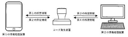
- a processing device connected to the first information processing device, and transmitting the fifth predetermined information from the first information processing device to the third information processing device, or from the third information processing device to the first information processing device; Transmitting the sixth predetermined information; or (D) transmitting the sixth predetermined information to the second information processing apparatus.
- the third information processing device is connected to the third information processing device by a predetermined method, and the seventh predetermined information is transmitted from the second information processing device to the third information processing device, or the third information processing device is Transmitting an eighth predetermined information to the second information processing apparatus; and / or transmitting an eighth predetermined information to the second information processing apparatus.
- a unique device ID or a unique device ID in combination with the electrode code is stored in the communication processing unit, and the device ID is stored in at least one of the first or third predetermined information. And an information communication method.
- the device ID that is unique in combination with the electrode code is unique when the first information processing device recognizes the electrode code that is different from the combination. Is determined as an erroneous recognition.
- At least one of the first to third information processing apparatuses has a first specific code for specifying the information processing apparatus and / or a second specific code set by operating software. Then, at least one of the second, fourth, fifth, sixth, seventh and eighth predetermined information transmitted from the information processing apparatus having the specific code includes the first or second specific information.
- An information communication method including any of the codes.
- the first information processing device recognizes a communication address including at least a part of the electrode code, or a communication address corresponding to at least a part of the electrode code, and recognizes one or more of the third or more third addresses.
- the third information processing device is characterized by an information communication method including the second information processing device.
- a right or wrong of at least one of the first to eighth predetermined information received by the device according to any one of claims 1 to 21 and the first to third information processing devices is determined by a predetermined value. And an information communication method.
- an information communication method is characterized in that at least one of the first to eighth predetermined information includes predetermined data and encrypted information obtained by encrypting the predetermined data.
- an information communication method is characterized in that the encrypted information is information obtained by encrypting encoded data obtained by encoding the predetermined data by an encoding unit by an encryption unit.
- the information processing device that has received the predetermined information, the encoded information obtained by decoding the encrypted information by a decoding unit, and the encoded information obtained by encoding the predetermined data by the encoding unit.
- the predetermined processing may be a connection state between the third information processing apparatus and the first or second information processing apparatus, or the communication processing unit and the first information processing apparatus and / or An information communication method including a process of disconnecting at least one of a connection state with a second information processing apparatus is characterized.
- the information processing method is characterized in that the communication processing unit has a clock function and the first and / or third predetermined information includes time information or information that changes with time.
- An information communication system comprising: a device according to the present invention; and a first information processing device connected to a touch panel that detects a change in a physical quantity and detects one or more positions.
- the first information processing device recognizes an electrode code formed by an electrode detected by the touch panel among the plurality of electrodes by contacting or substantially contacting a plurality of electrodes arranged on a bottom surface of the housing of the device.
- An information communication system is characterized in that a communication processing unit provided in a housing of the device and the first information processing device are connected based on at least a part of the electrode cord.
- the apparatus further includes a second and / or third information processing device, An information communication system, wherein information processing is performed by the information communication method according to any one of claims 26 to 38.
- the information processing system is characterized in that the first information processing device is a smartphone.
- a touch panel connected to the first information processing device which detects a change in physical quantity and detects one or more positions, includes a plurality of touch panels arranged on the bottom surface of the housing of the device according to the present invention.
- the first information processing device recognizes an electrode code formed by the electrode detected by the touch panel, by contacting or substantially contacting the electrode, based on at least a part of the electrode code,
- An information communication method according to the present invention is characterized by a program for connecting the first information processing device and a communication processing unit provided in a housing of the device.
- a program which further includes a second and / or third information processing device, and executes information processing by the information communication method according to the present invention.
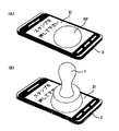
- FIG. 2 is a schematic diagram illustrating an outer shape of the code generator according to the first embodiment.
- 3 is a diagram illustrating an example of a code generation device according to Embodiment 1.
- FIG. (A) is a diagram showing a conductive pattern printed on a conductive pattern printing sheet, and (B) is a diagram showing a shape when the conductive pattern printing sheet is attached to a lower housing.
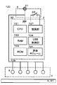
- FIG. 3 is a circuit schematic diagram of the code generator according to the first embodiment.
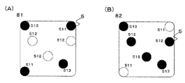
- (A) schematically shows a first conductive pattern detected by the touch panel in a state where the code generator touches the touch panel by touching the human body contact electrode, and
- (B) shows a push button of the code generator.
- FIG. 9 is a schematic diagram illustrating an outer shape of a code generator according to a second embodiment.
- FIG. 9 is a diagram illustrating an example of a structure of a code generation device according to a second embodiment.
- FIG. 9 is a diagram illustrating an example of a structure of a code generation device according to a second embodiment. It is a figure which shows the electrode detection outline
- FIG. 13 is a schematic diagram illustrating an outer shape of a code generator according to a third embodiment.
- FIG. 14 is a circuit schematic diagram of a code generator according to a fourth embodiment.
- FIG. 14 is a schematic diagram illustrating an outer shape of a code generator according to a fourth embodiment.
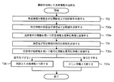
- FIG. 18 is a diagram illustrating a method of determining electrode detection coordinates (STEP 1) and (STEP 2) for pattern coding according to the fifth embodiment.
- FIG. 4 is a diagram illustrating a coordinate conversion method for pattern coding.
- FIG. 21 is a flowchart illustrating an example of a pattern encoding process according to the fifth embodiment.
- FIG. 16 is a schematic diagram illustrating an outer shape of a code generator according to a sixth embodiment.
- FIG. 14 is a schematic diagram illustrating a configuration of a code generation device according to a sixth embodiment.
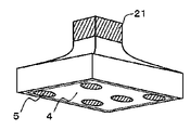
- FIG. 15 is a schematic sectional view showing the structure of a code generator according to a sixth embodiment.
- FIG. 21 is a schematic diagram showing a form of a code generation device which is a modification of the sixth embodiment.
- FIG. 21 is a schematic diagram showing a form of a code generation device which is a modification of the sixth embodiment. It is a figure showing the code specification of the multicode stamp which can set up a plurality of stamp codes by a slide switch. It is a flowchart figure which shows the authentication system using an electronic stamp.
- 5 is an embodiment of a code generator equipped with a dot code reader.
- 5 is an embodiment of a code generator equipped with an optical code reader.
- 5 is an embodiment of a code generator equipped with an optical code reader. It is an example which shows the synchronization by an optical code reader. It is an example which shows the time series change of the synchronization by an optical code reader.
- FIG. 2 is a diagram illustrating a connection between a code generation device and an information processing device.
- FIG. 2 is a diagram illustrating a connection between a code generation device and an information processing device. It is the figure which illustrated the position where an electrode can be arrange
- (A) is a schematic side view showing an example of the appearance of the stamp-type code generator 120
- (B) is a schematic top view
- (C) is a schematic bottom view.
- FIG. 3 is a schematic cross-sectional view of a side surface of the code generator 120 cut in a vertical direction.
- (A) is a schematic side view showing an example of the appearance of the stamp-type code generator 120
- (B) is a schematic top view
- (C) is a schematic bottom view.
- (A) is a schematic diagram of the configuration of the code generator 121
- (B) is a diagram illustrating an example of a switch circuit of the conduction control unit.
- FIG. 3 is a schematic cross-sectional view of a side surface of a code generator 121 cut in a vertical direction.
- This is a stamp shape applicable as a code generator including a communication processing unit.
- This is a stamp shape applicable as a code generator including a communication processing unit.
- an electrode pattern composed of five electrodes is formed in five stages. This is an example in which an electrode pattern including five electrodes is formed in four stages. This is an example in which an electrode pattern composed of five electrodes is formed in three stages. This is an example in which an electrode pattern composed of five electrodes is formed in two stages. This is an example in which an electrode pattern composed of five electrodes is formed in five stages.
- FIG. 9 is a flowchart illustrating transmission and reception of information between a code generation device and an information processing device.
- 9 is a flowchart illustrating transmission and reception of information between a code generation device and an information processing device.
- 9 is a flowchart illustrating transmission and reception of information between a code generation device and an information processing device.
- 9 is a flowchart illustrating transmission of encryption information by a code generation device.
- 9 is a flowchart illustrating transmission of encryption information by a code generation device.
- 9 is a flowchart illustrating transmission of encryption information by a code generation device.
- FIG. 4 is a diagram illustrating transmission and reception of information between a code generation device and an information processing device.
- 5 is a flowchart illustrating transmission and reception of information between a code generation device and an information processing device.
- FIG. 4 is a diagram illustrating transmission and reception of information between a code generation device and an information processing device.
- FIG. 4 is a diagram illustrating transmission and reception of information between a code generation device and an information processing device.
- 9 is a flowchart illustrating transmission and reception of information between a code generation device and an information processing device.
- 9 is a flowchart illustrating transmission and reception of information between a code generation device and an information processing device.
- FIG. 4 is a diagram illustrating transmission and reception of information between a code generation device and an information processing device.
- 9 is a flowchart illustrating transmission and reception of information between a code generation device and an information processing device.
- FIG. 4 is a diagram illustrating transmission and reception of information between a code generation device and an information processing device.
- 9 is a flowchart illustrating transmission and reception of information between a code generation device and an information processing device.
- FIG. 4 is a diagram illustrating transmission and reception of information between a code generation device and an information processing device.
- 9 is a flowchart illustrating transmission and reception of information between a code generation device and an information processing device.
- FIG. 4 is a diagram illustrating transmission and reception of information between a code generation device and an information processing device.
- 9 is a flowchart illustrating transmission and reception of information between a code generation device and an information processing device.
- (A) shows an example of a schematic top view of a card-type code generator 120a
- (B) is a schematic side view
- C) is a schematic sectional view
- (D) is a schematic bottom view.
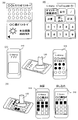
- E is a schematic configuration diagram. It is a figure showing the Example of the personal authentication service using the present invention.
- FIG. 2 is a diagram illustrating an information service using a print medium using the present invention. It is a figure showing the mail-order service by the print media which used this invention. It is a figure showing the entertainment service which used this invention. It is a figure showing the information transfer service using the present invention. It is a figure showing the dot code formation medium information link using the present invention.
- FIG. 34 is a schematic external view of a code generator according to a thirteenth embodiment.
- 138 is an example of a substrate pattern of a first substrate according to Embodiment 13.
- FIG. 39 is an explanatory diagram of the wiring connection method of the electrodes of the first substrate according to the thirteenth embodiment.
- FIG. 39 is a board pattern diagram of a second board of the thirteenth embodiment.
- FIG. 39 is an explanatory diagram of a wiring connection method between a first substrate and a second substrate according to the thirteenth embodiment.
- FIG. 21 is a cross-sectional view of a code generator according to a thirteenth embodiment and a connection state explanatory diagram.
- 129 is an explanatory diagram of Modification Example 1 of the code generation device of Embodiment 13. [FIG.
- FIG. 129 is an explanatory diagram of Modification Example 2 of the code generator of Embodiment 13.
- FIG. 129 is an explanatory diagram of Modification 3 of the code generator of Embodiment 13.
- FIG. 129 is an explanatory diagram of Modification Example 4 of the code generation device of Embodiment 13.
- FIG. 32 is a schematic external view and a cross-sectional view of a code generation device according to a fourteenth embodiment.
- FIG. 28 is an explanatory diagram of a switch operation of the code generator according to the fourteenth embodiment.
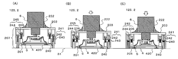
- FIG. 35 is a diagram schematically illustrating a drive mechanism of a code generator 125 according to a sixteenth embodiment.
- FIG. 35 is a diagram schematically illustrating a driving mechanism of a code generation device 126 according to a sixteenth embodiment.
- FIG. 21 is a schematic diagram showing a structure of a code generation device according to a seventeenth embodiment.
- FIG. 21 is a schematic diagram showing a structure of a code generation device according to a seventeenth embodiment.
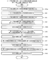
- 9 is a flowchart illustrating an overall image of information processing.
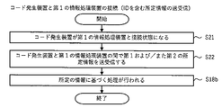
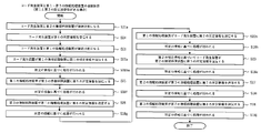
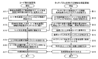
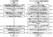
- 5 is a flowchart showing a process of connecting a code generator and a first information processing device.
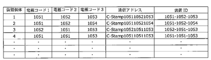
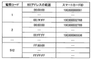
- 5 is a flowchart showing a process of connecting a code generator and a first information processing device. It is a table which illustrates mapping of an electrode code and BD address. It is a figure showing the example of application of a POS system.
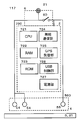
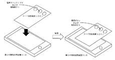
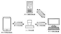
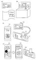
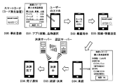
- FIG. 1 is a diagram illustrating an example of an external configuration of an information processing system according to an embodiment of the present invention.
- the information processing system shown in FIG. 1 includes a code generator 1 for generating a code, a code recognition device 3 for recognizing the code, and a server 4 for executing a predetermined process related to the code.
- the code recognition device 3 and the server 4 are connected via a predetermined network N such as the Internet.
- the code recognition device 3 is configured by an information processing device such as a smartphone having a touch panel 31 or a tablet.
- the touch panel 31 includes a display unit and a capacitance-type position input sensor stacked on the display surface of the display unit.
- the touch panel 31 displays an area SP (hereinafter, referred to as a “code detection area SP”) for detecting an electrode group indicating a pattern code output by the code generation device 1.
- the code recognition device 3 includes a detection unit and a recognition unit as functional blocks (not shown).
- the function block may be constituted by hardware alone, but in the present embodiment, it is assumed that the function block is constituted by software and hardware. That is, the detection unit and the recognition unit exert the following functions by cooperation of software and hardware.
- the detecting unit based on the detection result of the position input sensor, when one or more electrodes 5 connected to the human body with low impedance by the code generator 1 contact or approach the code detection area SP of the touch panel 31. A conductive pattern as arrangement information of one or more electrodes 5 is detected.
- the recognition unit recognizes the pattern code generated by the code generator of the code generator 1 based on the detected conductive pattern of the one or more electrodes.
- This pattern code is sent to the server as needed.
- the server executes various processes based on the pattern code.
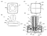
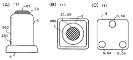
- FIG. 2 is a schematic diagram illustrating an outer shape of the code generator 111 according to the eleventh embodiment.
- 2A is a top view
- FIG. 2B is a side view
- FIG. 2C is a bottom view
- FIG. 2D is a cross-sectional view taken in a vertical direction.
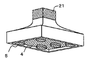
- the code generator 111 has a shape similar to a square stamp
- the upper part of the housing 2 is a push button of the push button switch of the operation unit 6.
- the handle portion 222 is formed of a conductor so as to be able to be naturally touched while being held in the hand, and is used as the human body contact conductive material 21.
- a conductive pattern of 0.188 mm thick PET resin printed with conductive ink on the electrode 5 is printed.
- the sheet 400 is adhered with a double-sided adhesive tape having a thickness of 50 ⁇ m so that the position of the electrode 5 is not shifted and the strength is such that the sheet 400 can be easily peeled off.
- the thickness and the material of the conductive pattern printing sheet 400 are such that the electrode 5 is detected by the touch panel 31 when it comes into contact with the touch panel 31 through the base material of the sheet.
- the thickness and the material are not limited to the above and may be any thickness and material as long as durability enough to withstand the operation can be secured.
- a polypropylene resin sheet or a high-quality paper for photo printing coated with PP may be used.
- the bonding method is not limited to a double-sided tape, but may be a method of applying an adhesive, as long as the bonding surface can be easily peeled off without causing displacement of the bonding surface.
- the conductive ink used for printing the conductive pattern printing sheet 400 may be any ink having conductivity such as silver paste ink, silver salt ink, silver nano ink, carbon ink, and the like. From the viewpoint of the wiring time constant, the necessity of the flattening process of the ink layer, the disconnection of the wiring pattern, the failure rate such as the increase in resistance, etc., the minimum wiring width used in the conductive pattern is 0.8 mm or more in the carbon ink. 1.0 mm or less, and more preferably 0.6 mm or more and 1.0 mm or less as long as the defect rate such as disconnection of the wiring pattern and increase in resistance is within an allowable range.
- the thickness is preferably 0.2 mm or more and 0.3 mm or less. If the defect rate such as disconnection of the wiring pattern and the increase in resistance is within an allowable range, 0.1 mm or more and 0.2 mm or less. More preferred.
- the wiring method described later is adopted, and the minimum wiring width may be 0.8 mm or less. Is preferably about 100 ⁇ / mm, and may be 1 K ⁇ / mm or less.
- the thickness of the ink layer of the electrode 5 and the wiring to be formed by printing is preferably as small as possible, and is preferably 10 ⁇ m or less, and may be 20 ⁇ m or less which does not require a flattening process.
- a guide groove 205 shallower than the thickness of the conductive pattern printing sheet 400 including the double-sided adhesive tape is provided on the bottom surface 4 and the side surface of the lower housing 201.
- the design can be improved.
- the conductive pattern printing sheet 400 is in an exposed state, the electrodes of the touch panel 31 are provided for the purpose of protecting the sheet and the outer printing surface and preventing slippage (position shift) when the sheet is brought into contact with the touch panel 31.
- a protective sheet such as a thin silicon sheet of about 50 ⁇ m which does not hinder detection can be attached. When a protective sheet is attached, the thickness of the conductive pattern printing sheet 400 is preferably reduced to about 0.125 mm in consideration of the thickness of the protective sheet.
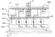
- a substrate 611 is fitted to the upper surface of the lower housing 201.
- board connection terminals 612 are arranged at equal intervals on the outer peripheral portion on the front surface side of the board 611, and as shown in FIG.
- a sheet connection terminal 404 is provided at a position corresponding to the marginal portion 403 provided at the tip of the side surface affixing portion 402 of 400.
- the board connection terminals 612 on the surface of the board 611 are formed by folding the marginal portion 403 of the conductive pattern printing sheet 400 affixed to the lower housing 201 onto the board 611 and screwing the board sheet presser 202 from above.
- the conductive pattern can be electrically connected to the conductive pattern connection terminal 404 provided on the folded portion 403 of the conductive pattern printing sheet 400 by pressing.
- a conductive adhesive or a conductive double-sided tape is applied between the connection terminals. By applying or attaching, conduction between the connection terminals can be ensured.
- the connection resistance between the connection terminals may be lower than about several tens of K ⁇ .
- the substrate sheet presser 202 includes a flat fixing portion that can simultaneously fix the outer periphery on the surface of the lower housing 201 to the substrate 611 and the conductive pattern printing sheet 400, and an outer frame portion that covers the side surface of the lower housing 201. Is provided.
- the outer frame portion while protecting the side surface portion of the conductive pattern printing sheet 400, it is formed into a shape that covers almost all the side surfaces of the code generator 111, and the outer surface of the outer frame portion is colored or patterned.
- the design of the code generator 111 can be improved.
- the board sheet presser 202 can be a simple flat plate without an outer frame portion.
- the substrate 611 has openings at four locations on the inner portion corresponding to the vertices of the rectangle, and is positioned with the lower housing 201 by inserting a substantially columnar support 206 projecting from the lower housing 201. You.
- the substrate 611 is also opened at the center of the substrate, the lower movable contact portion 251 is slidably inserted from the back surface to the front surface, and the upper movable contact portion 252 provided on the upper surface of the substrate 611 and the substrate 611 are connected. It is fixed as if sandwiched.
- a short wiring pattern is provided between the substrate connection terminal 612 provided on the outer peripheral portion of the surface of the substrate 611 and the upper fixed contact 613 provided around the surface of the central opening.
- a lower fixed contact 614 is provided around the back surface of the central opening of the substrate 611, and the shortest distance between the outer peripheral portion of the front surface via a thin wiring pattern and a through hole. It is connected to the board connection terminal 612.
- connection specifications from the board connection terminal 612 to the fixed contacts 613 and 614 in the central opening, (a) one in which the lower fixed contact 614 is provided only on the back surface, and (b) that in the front surface of the board 611. Only the upper fixed contact 613 is provided, and (c) the fixed contacts 613 and 614 are provided on both the front and back surfaces.
- At least one set is provided on each side of the substrate 611, and the total of each side is (a) and (b): 5 sets or 5 or more sets, and (c) is 4 sets. All you need is a pair. This is because the number of simultaneously detectable multi-touches set on the touch panel 31 of the smartphone such as the iPhone (registered trademark) which is the code recognition device 1 and the number of simultaneously detectable multi-touches are set between the electrode 5 of the conductive pattern printing sheet 400 and the board connection terminal 612 This is to ensure ease of wiring.
- the total number of sets of connection specifications required for each side of the board is (a) and (b), the number of multi-touches. Or, more than that, (c) is the number of multi-touches-1.
- connection specifications are used in accordance with the electrode detection specification of the conductive pattern to be created, (a) is used for an electrode detected on the touch panel 31 only when the second conductive pattern is used, and (b) is used for the first conductive pattern. It is used for an electrode detected on the touch panel 31 only in the case of a conductive pattern, and (c) is used for an electrode detected in both the first and second conductive patterns.
- the lower movable contact portion 251 has a structure in which a flange portion 253 is provided below a columnar member having a substantially rectangular shape in a plan view, and is entirely conductive.
- a contact interval between a portion where the lower fixed contact 614 of the substrate 611 contacts the lower movable contact 251 is located at a position facing the lower fixed contact 614 provided at the center opening of the back surface of the substrate 611 of the flange 253.
- a movable contact 254 made of elastic conductive rubber is provided in order to absorb the variation of the contact and make contact between all the contacts.
- the movable contact 254 is not limited to the conductive rubber, but may be a leaf spring contact or the like as long as it has elasticity, can absorb variations in contact intervals, and can conduct all contacts.
- the upper movable contact portion 252 has a structure in which a step portion 255 is provided on a columnar body having a substantially rectangular shape in a plan view, a concave portion is provided at the center of the column, and the lower movable contact portion 251 is inserted and fitted. Having. The position of the step portion 255 facing the upper fixed contact 613 provided at the center opening of the surface of the substrate 611 absorbs the variation in the contact interval of the portion where the upper fixed contact 613 on the substrate 611 contacts the upper movable contact portion 252.
- a movable contact 256 made of elastic conductive rubber is provided to make contact between all the contacts. Further, the movable contact 256 is not limited to the conductive rubber, similarly to the lower movable contact portion 251.
- the upper movable contact portion 252 has a latch structure on the upper portion, and is fitted and fixed to the upper housing 203.
- the upper housing 203 is provided with a cylindrical opening through which the support 206 is slidably inserted at a position corresponding to the support 206 projecting from the lower housing 201.
- At the bottom of the cylindrical opening there is a step where the diameter of the opening is reduced, and the spring is inserted into the support 206 and sandwiched between the lower housing 201 and the upper housing 203.
- the flanged screw is fixed to the support 206 through which the.
- the upper housing 203 and the lower housing 201 are slidably fixed, and a contact driving mechanism for the conductive pattern switching push button switch of the code recognition device 111 is formed.
- the lower fixed contact 614 and the movable contact 254, and the upper fixed contact 613 and the movable contact 256 are provided with appropriate intervals so that both contacts do not contact at the same time during the switching operation. It has become. This is to prevent the number of simultaneously detectable multi-touches set on the touch panel 31 of the smartphone such as iPhone (registered trademark) from being restricted.
- the structure from the lower housing 201 to the upper housing 203 is the main body 207.
- a holding portion 204 is attached to the upper housing 203 in a removable structure.
- the holding portion 204 includes a non-conductive lid portion that covers the upper housing 203 and enhances design, and a conductive handle portion 222 corresponding to a handle of the stamp.
- the handle 222 contacts and conducts with the upper movable contact 252.
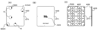
- FIG. 4 (A) shows a conductive pattern diagram printed on the conductive pattern printing sheet 400
- FIG. 4 (B) shows a shape when the conductive pattern printing sheet 400 is attached to the lower housing 201.
- the conductive pattern is printed with a conductive ink on a surface which becomes inside in a state where the conductive pattern printing sheet 400 is attached to the lower housing 201.
- the conductive pattern has the shortest distance between the circular electrode 5 having a diameter of 8 mm provided on the bottom surface 4 and the sheet connection terminal 404 provided on the folding portion 403, which has the minimum printable line width for each electrode. Connected in a print pattern as shown.
- the electrode 511 detected by the touch panel 31 with the first conductive pattern 81 is connected to the sheet connection terminal 404 to which the symbol (a) is added, and the electrode 512 detected by the touch panel 31 with the second conductive pattern 82 is , (B) are connected to the sheet connection terminal 404 and the electrodes 513 detected by the touch panel 31 on both the first and second conductive patterns 81 and 82 are provided with the code (c).
- Sheet connection terminal 404 Sheet connection terminal 404.
- the electrode 5 arranged at the center of the bottom surface 4 is connected to the original wiring connected to the sheet connection terminal 404 through the center point of the electrode 5 for connection.
- the wiring is drawn with a length about the radius of the electrode 5.
- the touch panel 31 detects the wiring part in addition to the electrodes due to the parasitic capacitance generated between the wiring and the touch panel when placed on the touch panel 31, and the detection coordinates of the electrodes are shifted in the wiring direction. Occurs. Therefore, when the wiring printed on the area of the bottom surface 4 is a long electrode, the wiring is extended in the direction opposite to the original wiring as shown in FIG. Is also generated, and the shift amount of the detection coordinates of the electrode can be reduced. If the wiring in the area of the bottom surface 4 is a short electrode, the extension wiring is unnecessary.
- Table 1 shows that five electrodes having a diameter of 8 mm were formed with carbon ink on the inner surface of a PET resin sheet having a thickness of 0.188 mm at a 7 ⁇ 7 electrode arrangement grid grid spacing of 7 mm. This is a comparison of the result of evaluating the displacement of the detection coordinates when the connected evaluation sample was detected 20 times on the touch panel of the smartphone (iPhone 6) with or without the extension wiring.
- the sample having the extension wiring is provided with the extension wiring of 0.8 mm in width and 4 mm in the direction 180 ° opposite to the original wiring.
- the detection coordinates on the touch panel are determined by using the lower left and upper right electrodes 511 as reference electrodes in the conductive pattern of FIG. was converted to the arrangement coordinates with a grid interval of 7 mm, and the other three electrodes (electrodes 2 to 4 in Table 4) were evaluated based on what percentage of the grid interval deviated from the arranged grid. It was confirmed that the shift amount can be reduced by 10% on average with the wiring.
- the wiring between the electrodes 5 for forming the conductive pattern was detected with the parasitic capacitance between the touch panel and the wiring with respect to the touch panel 31 when the wiring width was 0.8 mm.
- the wiring width between the electrodes 5 is preferably 0.8 mm or less, more preferably 0.2 mm or less, within the range of the allowable wiring width in which the conductive ink can be printed (wiring resistance does not increase).
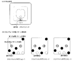
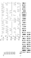
- FIG. 5 is a schematic circuit diagram of the code generator 111.
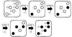
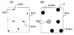
- FIG. 6A schematically shows a first conductive pattern 81 detected by the touch panel 31 in a state where the code generation device 111 touches the human body contact electrode 21 and is in contact with the touch panel 31 (STEP 1).
- 6 (B) schematically shows the second conductive pattern 82 detected by the touch panel 31 in a state where the push button of the code generation device 111 is pressed (STEP 2) from (STEP 1).
- the code generator 111 selectively connects the electrodes 5 and the wirings formed by printing the conductive pattern printing sheet 400 with the conductive ink to the sheet connection terminals 404 and the substrate connection terminals 612 of the substrate 611.
- the first conductive pattern 81 and the second conductive pattern 82 can be set to be changeable only by changing the print pattern of the conductive pattern print sheet 400 by connecting (a), (b), and (c). It is.
- the first conductive pattern 81 is formed by connecting the sheet connection terminals 404 connected from the electrodes 5 (511, 513) of the conductive pattern printing sheet 400 to the substrate connection terminals 612 (a) and (c) of the substrate 611. I do.
- the second conductive pattern 82 is formed by connecting the sheet connection terminal 404 connected from the electrode 5 (512, 513) of the conductive pattern printing sheet 400 to the substrate connection terminal 612 (b) and (c) of the substrate 611. I do.
- the first conductive pattern 81 is three or more so that the orientation of the first conductive pattern 81 placed on the touch panel 31 of the code generator 111 can be specified, and the arrangement of the electrodes 5 is not rotationally symmetric. It is preferable to set the number to five or less from the restriction on the number of multi-touches.
- the orientation of the contacted code generator 111 on the touch panel 31 is specified from the code decoding processing result of the first conductive pattern 81.
- the second conductive pattern 82 can perform a code decoding process using the information of the direction, so that a pattern in which the arrangement of the electrodes 5 is rotationally symmetric can also be used as the conductive pattern. Therefore, the number of codes of the second conductive pattern 82 can be dramatically increased.
- the number of codes is equal to that of the first conductive pattern 81.
- the multiplication of the second conductive patterns 82 results in a dramatic increase in the number of codes that can be set in the code generator 111.
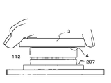
- FIG. 7 is a schematic diagram illustrating an outer shape of the code generator 112 according to the twelfth embodiment.
- 7A is a top view
- FIG. 7B is a side view
- FIG. 7C is a bottom view
- FIG. 7D is a cross-sectional view taken in the vertical direction.
- the code generator 112 differs from the first embodiment only in the structure of the holding unit 204a, and the main body 207 is the same as the code generator 111 of the first embodiment. And the same parts.
- the code generation device 111 is a stamp type, and holds the handle portion 222 by hand, touches the human body contact electrode 21, contacts the touch panel 31 such as a smartphone as the code recognition device 3, and presses the conductive member.
- the touch panel 31 detects a conductive pattern formed on the pattern printing sheet 400, and further switches the conductive pattern with a push button switch to generate a pattern code in time series.
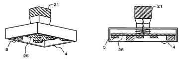
- the code generator 112 is used in a state where the main body 207 is attached to the flat holding portion 204a with the bottom surface 4 facing up. As shown in FIG. 7A, mounting holes 208 are provided at four corners of the flat holding portion 204a, and the mounting portion can be fixed to a wall or the like with the mounting holes 208 and screws. As shown in FIG. 8, the touch panel 31 is pressed against the bottom surface 4 of the code generation device 112 while holding the smartphone or the like as the code recognition device 3 by hand.
- the code generator 112 is installed on a wall, a desk, or the like near an exhibition display of a museum, and a visitor contacts the touch panel 31 such as a smartphone with the code generator 112 to obtain information on an exhibit.
- the code generator 112 is installed on the desk in the railway station yard, and the passenger can touch the touch panel 31 such as a smartphone to the code generator 112 to obtain stamp rally points. It is.
- the touch panel 31 it is necessary for the touch panel 31 to detect the conductive pattern formed on the conductive pattern print sheet 400 without the finger or the hand touching the human body contact electrode 21 and without conducting to the human body. (Human body non-conductivity detection)
- FIG. 9A shows a comparison between the mounting structure of the holding unit 204 of the code generator 111 and the main body 207
- FIG. 9B shows a comparison of the mounting structure of the holding unit 204a and the main body 207 of the code generator 112.
- the upper surface of the upper housing 203 of the main body 207 is provided with a fitting groove 210 in which a part of the opening on the upper surface side is narrowed.
- a thick cylindrical projection 209 is provided.
- FIGS. 10A and 10B schematically show the operation of detecting the electrode 5 of the general capacitive touch panel 31.
- FIG. (A) puts the code generator 111 on the touch panel 31 and performs a detection operation (a human body conduction detection method) in a state where a person touches it.
- a capacitance type touch panel 31 has a size of about 4 mm to 6 mm inside the touch panel 31 in order to detect the presence or absence of a finger touch on the surface of the touch panel and the touch position.
- a large number of TXn and RXn are arranged in a mesh so as to intersect vertically at intervals, and a capacitance Cm for detecting a touch is provided at the intersection of TXn and RXn.
- a capacitance is formed between Tap and TXn and between Tap and RXn, and the combined capacitance Cm 'between TXn and RXn is smaller than Cm.
- a voltage amplitude (AC signal) of about several hundred KHz is sequentially applied to a large number of TXn, and a current In flowing to the RXn side is measured for a large number of RXn, and at the intersection of the corresponding TXn and RXn being Tapped.
- the change in the capacitance of Cm ′ is measured by the change in the current value In, and the position (coordinate) of the Tap on the touch panel 31 is specified.
- the code generator 111 is placed on the touch panel 31 and the electrode 5 having a diameter of about 8 mm printed on the conductive pattern printing sheet 400 is tapped at any position on the touch panel 31. Then, the capacitance Cm ′ is changed by the electrode 5.
- the capacitance Cm ′ is changed by the electrode 5.
- Tap1 in FIG. 10A only one electrode 5 separated from the human body by a push button switch (not shown) built in the code generator 111 has a small change amount of Cm ′, and the current I1 Since the change is small, it does not reach the determination threshold value for the coordinate detection of the touch panel 31.
- the human body contact electrode 21 has a coupling capacitance Cp2 with the human body, and the voltage amplitude (AC signal) of TX2 is the coupling capacitance.
- a minute current is also applied to the human body via Cp2. For this reason, the amount of change in the current I2 of the RX2 becomes large, and exceeds the determination threshold value for the coordinate detection of the touch panel 31, and the position of the electrode 5 is detected.
- the electrodes 5 printed on the conductive pattern printing sheet 400 used in the code generator 112 must be transmitted via a substrate 611 (not shown) and a push button switch.
- the plurality of electrodes 5 are connected to each other.
- the electrodes 5 of Tap1 to Tap4 are connected to form a conductive pattern.
- an additional capacitance Cp2 'added to a conductive sheet 211 and a substrate 611 described later is provided at a common node to which the electrode 5 is connected.
- each electrode of the other Tap1, Tap3, and Tap4 via the common node. 5 has a coupling capacitance with TXn and RXn, and the voltage amplitude (AC signal) of TX2 causes a small current In to flow through RXn via the respective coupling capacitance. Further, the additional capacitance Cp2 'also becomes a coupling capacitance, and a small current flows to the ground.
- AC signal voltage amplitude
- the amount of change in the current I2 of the RX2 becomes large and exceeds the determination threshold value for the coordinate detection of the touch panel 31, and the position of the electrode 5 is detected.
- the touch panel 31 sequentially switches between TXn and RXn, and a certain position of another electrode 5 is reached, a small current is similarly applied to the coupling capacitance of the electrode 5 located outside the target TXn and RXn. Therefore, it is possible to make the touch panel 31 detect the positions of all the electrodes 5 connected to the common node.
- the electrodes 5 are all arranged on different TXn and RXn, the actual conductive patterns of the touch panel 31 and the code generator 112 are two-dimensional (planar).
- the plurality of electrodes 5 are arranged on a common TXn or a common RXn. At this time, the total effective capacitance may be reduced as compared with the case where all the electrodes 5 are arranged on different TXn and RXn.
- the capacitance CfR between the electrode and the RXn of the two electrodes 5 is equal to the combined capacitance of the series-connected capacitors.
- the terminal on both sides has the same configuration as that connected to the same RXn node, and the capacitance becomes invisible to RXn effectively.
- the electrode arrangement position of the conductive pattern on the touch panel 31 and the electrode detection performance depend on each other. Normally, the TXn and RXn on the touch panel 31 are arranged vertically and horizontally on the square touch panel surface. Therefore, when a plurality of conductive pattern electrodes 5 are arranged vertically or horizontally on the touch panel surface, the electrodes are detected. It becomes spicy.
- both the conductive patterns 81 and 82 be conductive patterns using a plurality of electrodes 5, within the limit of the number of multi-touches of the code recognition device 3. In this case, the more stable the detection, the more electrodes 5 are used.
- a conductive sheet 211 for adding capacitance is provided with an upper movable electrode portion 252 and a conductive region of the conductive sheet. Affixed for connection (conduction). Further, the capacitance-adding conductive sheet 211 may be attached to the upper surface of the flat holding portion 204a instead of the upper surface of the upper housing 203.
- the conductive sheet 211 for adding capacitance may be a sheet such as a copper film having conductivity as a whole, or a sheet having a conductive pattern formed by printing with a conductive ink similarly to the conductive pattern printing sheet 400. .
- the wiring can be provided in a loop shape of approximately 12.5 cm and resonated with a WiFi radio wave having a frequency of 2.5 GHz to assist the electrode detection of the touch panel 31. Further, the conductive sheet 211 may be omitted.
- a conductive material to be connected to the movable electrode portion is provided in an empty area of a pattern having no wiring or contact on the front and rear surfaces of the substrate 611 shown in FIGS.
- a pattern may be formed to serve as an additional capacitor.
- a conductive pattern may be formed as a wiring in a region of the conductive pattern printing sheet 400 shown in FIG. 4A where there is no electrode and no wiring, and may be connected to the movable electrode portion via the substrate 611 to provide an additional capacitance.
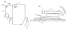
- FIG. 11 is a schematic diagram illustrating an outer shape of the code generator 112a according to the third embodiment.
- FIG. 11A is a top view in a use state
- FIG. 11B is a side view in a use state.
- the code generator 112a is obtained by changing the holding unit 204a of the code generator 112 for detecting the non-conduction of the human body to the human body conduction detection. There is no change from the code generator 112 except for the holding unit 204a and the method of use.
- the holding portion 204b of the code generator 112a is made larger in one direction than the plane size of the main body 207 so that the smartphone, which is the code recognition device 3, is in contact with the bottom surface 4.
- the size is such that the holding portion 204b can be easily touched.
- the holding portion 204b is made of a conductive resin, or a resin surface plated with metal, made of metal, and has conductivity.
- the holding portion 204b fits and rotates a fitting groove 210 provided in the upper housing 203 of the main body portion 207 and a fitting protrusion 209 on a mounting surface of the holding portion 204b, similarly to the holding portion 204a.
- the holding portion 204b and the main body 207 are fixed, and when the main body 207 is fixed, the upper movable contact portion 252 exposed on the upper housing 203 is pressed and electrically connected.
- the holding portion 204b becomes the human body contact electrode 21, and the code generator of the human body continuity detection system can be obtained.
- the smartphone 204 as the code recognition device 3 is held with the right hand, and the 204b is spread leftward on the premise that the holding unit 204b is touched with the left hand, but the 204b may be widened as a whole.
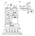
- FIGS. 12A and 12B are circuit schematic diagrams of a code generator 115 according to the fourth embodiment.
- FIG. 12A shows a case where an ID switching electrode 514 is provided on a first conductive pattern 81
- FIG. FIG. 9 is a circuit schematic diagram in a case where an ID switching electrode 514 is provided in the first embodiment.
- the specification of the code generator 115 is different from the specification of the code generator 111 in that an ID changeover switch 95 as an operation unit is added, and a plurality of conductive patterns are provided on one of the first and second conductive patterns 81 and 82. The difference is that it is possible.
- an SP3T (one-circuit, three-contact) slide switch 95 is provided between the fixed contact 614 on the back surface of the substrate 611b and the electrode 5, and an electrode 514 is provided for each contact terminal of the switch. Connecting.
- an SP3T (one-circuit, three-contact) slide switch 95 is provided between the fixed contact 614 on the back surface of the substrate 611b and the electrode 5, and an electrode 514 is provided for each contact terminal of the switch. Connecting.
- an SP3T type (one circuit, three contacts) slide switch 95 is provided between the fixed contact 613 on the surface of the substrate 611c and the electrode 5, and an electrode 515 is provided for each contact terminal of the switch. Connecting. Accordingly, it is possible to switch which electrode 515 is conducted to the human body contact electrode 21 by the second conductive pattern 82 depending on the position of the slide switch 95, thereby generating three different types of second conductive patterns 82. Can be done.
- FIG. 13 is a schematic view showing the outer shape of the code generator 115.
- FIG. 13A is a top view
- FIG. 13B is a side view
- FIG. 13C is a cross-sectional view taken in the vertical direction.
- the code generator 115 has a shape similar to a square stamp similarly to the code generator 111 shown in the first embodiment, and the upper part of the housing 2 has the operation unit 6. Since the push button switch is a push button, the housing 2 is held in hand and is in contact with the touch panel 31, and when pressed, two patterns of a first conductive pattern 81 and a second conductive pattern 82 are formed. Since codes can be sequentially generated and the ID changeover switch 95 is provided, it is possible to provide a plurality of either one of the first conductive pattern 81 or the second conductive pattern 82. It is a specification.
- openings 231 and 241 are provided in the upper housing 203 and the holding unit 204, respectively, and the switch 951 for operating the cord can be switched from the opening 241. It protrudes to the extent.
- a mark 242 corresponding to the code of the conductive pattern is provided at a portion corresponding to each switching position of the slide switch on a side of the opening 241 on the upper surface of the housing 2 along the direction in which the code switching switch operating portion 951 slides. Is provided.
- the mark 242 is formed in such a shape that a mark “ ⁇ ” indicating a number and a position is carved shallowly on the upper surface of the holding portion 204.
- the mark 242 is not limited to this, and may be provided in a convex shape, or may be formed by printing or attaching a seal. Further, the mark 242 is not limited to a numeral, and may be a graphic or the like corresponding to a use situation.
- the opening 241 provided in the holding unit 204 extends in a substantially arc shape counterclockwise in the center direction of the holding unit 204 in addition to a rectangular opening along the sliding direction of the cord switching switch operation unit 951. This is because, similarly to the code generator 111 of the first embodiment, the code generator 115 is provided with a mechanism for rotating and holding the holding unit 204 and the upper housing 203 shown in FIG. is there.
- the opening 231 provided in the upper housing 203 is large enough that the body portion of the slide switch 95 does not contact the upper housing 203 when the handle 222 is pressed to switch the push button switch of the operation unit 6. It is open at the end.
- the two types of circuit specifications corresponding to FIGS. 12A and 12B can be changed only by exchanging the boards 611b and 611c which differ only in the pattern wiring. Can be used commonly in the specifications.
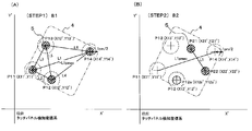
- FIG. 14 is an explanatory diagram of a method of determining (STEP1) and (STEP2) of the electrode detection coordinates for pattern coding, where (A) is the state of (STEP1) and (B) is the state of (STEP2). .
- FIGS. 15A and 15B are diagrams showing a coordinate conversion method for pattern coding.
- FIG. 15A is a diagram showing a detection state of the detection coordinate system of the touch panel 31.
- FIG. (C) is a state in which the detection state of (STEP 2) is converted to the electrode arrangement grid coordinate system of the code generator 1.
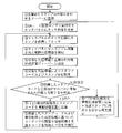
- FIG. 16 is a flowchart illustrating an example of the pattern encoding process of the code generator 1 having the operation unit 6 and capable of switching between the first conductive pattern 81 and the second conductive pattern 82.
- the code generator 1 capable of switching the conductive pattern, for example, by pressing the push button switch 60 which is the operation unit 6, the state before the press (STEP 1) and the state after the press (STEP 2) By switching between connecting and disconnecting the plurality of electrodes 5 provided as the first conductive pattern 81 and the second conductive pattern 82 to and from the human body conductive material 21, two types of codes can be generated. It is a specification that can be done.
- FIG. 15B shows an example of electrode arrangement of the first conductive pattern 81
- FIG. 15C shows an example of electrode arrangement of the second conductive pattern.
- the electrodes 5 are provided with an X, Y electrode arrangement grid coordinate system in the area of the bottom surface 4 of the code generator 1 in contact with the touch panel 31, and are arranged at integer coordinate points thereof. Thereby, the arrangement interval of each electrode 5 can be easily calculated from the unit grid interval of the grid coordinate system.
- the unit grid interval is set based on the size of the touch panel 31 that is assumed to be used, the coordinate detection position accuracy of the touch panel, the size of the bottom surface 4 of the code generator 1, the size of the electrode 5, and the like.
- the coordinate system is such that the area of the bottom surface 4 is divided into 0 to 6 for both X and Y.
- the arrangement of the electrodes 5 in each conductive pattern cannot be arranged at all the integer coordinate points, and the interval between the electrodes 5 and the restriction on the arrangement position are limited by the size of the electrode 5 and a plurality of electrodes as the conductive pattern.
- the determination is made in consideration of the influence on the detection coordinates of the touch panel 31 when 5 is arranged at a close coordinate position. For example, the minimum value of the electrode interval needs to be equal to or longer than the distance at which the two electrodes 5 are not detected as one electrode on the touch panel 31.
- a plurality of electrodes are arranged in parallel with the outer frame of the touch panel, a plurality of electrodes 5 Are arranged side by side, which may affect the detection of the touch panel 31. Therefore, the number of electrodes 5 arranged on the same line in the conductive pattern may be limited.
- the first conductive pattern 81 at least three electrodes 5 need to be detected so that the direction in which the code generator 1 is placed on the touch panel 31 can be specified.
- a maximum of five electrodes is preferable. Therefore, in the present embodiment, four electrodes 5 are provided in the first conductive pattern 81.
- the number of multi-touch is not limited or five or more tablets, or a case where a dedicated business device is used as the code recognition device 3
- the minimum number and the maximum number of electrodes are not limited to the above numbers.
- the first conductive pattern 81 it is preferable to provide a reference electrode in order to facilitate code decoding.
- all the first conductive patterns 81 are provided with two electrodes in the grid coordinate system (0, 0) and (6, 6) where the distance between the electrodes is the longest as a reference electrode.
- the length Lmax between the reference electrodes and the angle ⁇ 1 between the line connecting the reference electrodes and the X axis of the grid coordinate system can be used for code decoding.
- the reference electrode position is not limited to the coordinates of the present embodiment, but may be any one that can specify the angle between the reference electrode distance, the line connecting the reference electrodes, and the X axis of the grid coordinate system. Good.
- the reference electrodes at two points (0, 0) and (5, 6), and to make the code decoding processing algorithm correspond to the reference electrode position. Accordingly, a large number of conductive patterns of different code systems can be set. For example, a code system using two points (0,0) and (6,6) as reference electrodes in the embodiment, a code system using two points (0,0) and (5,6) as reference points, Furthermore, if a conductive pattern and a code decoding processing algorithm corresponding to each of a plurality of code systems are prepared and stored, such as a code system using another two points as reference points, the main body of the code generator 1 can be prepared. More code can be issued as a whole system without any changes.
- the information of the electrode arrangement coordinates of both the first conductive pattern 81 in (STEP 1) and the second conductive pattern 82 in (STEP 2) is stored in a code because of the feature of the switchable code generator 1. Since it can be used for decoding, a reference electrode is not required. For this reason, the second conductive pattern 82 can freely arrange the electrodes 5 at the arrangement coordinates according to only the restrictions on the intervals and arrangement of the electrodes 5.
- the number of arranged electrodes is one or more, and the electrodes can be freely arranged within the range of the number of constraints of the number of multi-touches. Therefore, more conductive patterns can be set as the second conductive patterns 82. In the present embodiment, one to four electrodes are arranged on the second conductive pattern 82.
- the electrode 5 of the second conductive pattern 82 is arranged at the same coordinate as the arrangement coordinate of the electrode 5 arranged on the first conductive pattern 81 due to the feature of the switchable code generator 1. It is also possible.
- the conductive pattern printing sheet 400 when the electrodes 5 of the first and second conductive patterns 81 and 82 are arranged at the same coordinates, the conductive pattern printing sheet The number of electrodes printed on 400 is smaller than the number of electrodes used in (STEP 1) and (STEP 2), and the arrangement of electrodes 5 of two types of conductive patterns becomes easy, and a large number of conductive patterns are set. Will be possible.
- a reference electrode is provided on the first conductive pattern 81, and the number of the electrodes 5 is three or more, so that the direction in which the first conductive pattern 81 is placed on the touch panel 31 can be specified.
- the reference electrode is not provided on the second conductive pattern 82, the reference electrode is provided on the second conductive pattern 82 and the number of the electrodes 5 is three or more. It is also possible to specify the orientation of the first conductive pattern 81 provided on the first conductive pattern 81 without providing a reference electrode. If the specification of the latter configuration is separately provided, more codes can be issued as a whole system without changing the main body of the code generator 1.
- a pair of reference electrodes can be provided by combining both patterns of the first conductive pattern 81 and the second conductive pattern 82. For example, by providing the reference electrode at the position (0, 0) on the first conductive pattern 81 and providing the reference electrode at the position (6, 6) on the second conductive pattern 82, the longest distance between the electrodes can be obtained. A distance is formed between the electrodes 5 of the first and second conductive patterns 81 and 82, and the touch panel is formed by using the electrodes 5 other than the reference electrode of one of the first and second conductive patterns 81 and 82. It is also possible to make it possible to specify the orientation placed on 31. As a result, the number of electrodes that can be freely arranged on both the first and second conductive patterns 81 and 82 increases, so that more conductive patterns can be provided and more codes can be issued as a whole system.
- the coordinates of the electrode arrangement coordinates of the first conductive pattern 81 and the second conductive pattern 82 created based on these specifications are standardized as standardized coordinate pattern codes for (STEP1) and (STEP2). Create a coordinate pattern code table.
- a first conductive pattern 81 of (STEP 1) and a second conductive pattern 82 of (STEP 2) are provided. It is a specification that two kinds of codes can be generated by switching between connecting and disconnecting a plurality of electrodes 5 respectively to and from the human body contact conductive material 21.
- the electrodes 5 that are not necessary for the respective conductive patterns 81, 82 in the respective conductive patterns 81, 82 are disposed on the bottom surface 4 of the code generating device 1.
- the touch position detection algorithm of the touch panel 31 of the smartphone 3 in order to continuously recognize the touch of the finger as the same touch, control for lowering the threshold value of the detection sensitivity of the touch position once detected (detection threshold value) is performed.
- the first conductive pattern 81 in (STEP 1) is connected to the human body contact conductive material 21.
- the detected electrode 5 may continue to be detected by the touch panel 31 even though it is cut off from the human body conductive material 21 by the second conductive pattern 82 in (STEP 2). A problem arises in that the pattern 82 cannot correctly recognize the code.
- the electrode arrangement specification of the conductive pattern according to the present embodiment complies with the following four conditions. (1) Four electrodes 5 including two reference electrodes are used in the first conductive pattern 81. (2) In the second conductive pattern 82, one to four electrodes 5 are used. Further, (3) in the electrode arrangement of the second conductive pattern 82, the electrode is not arranged at the electrode arrangement position of the first conductive pattern 81. (4) The distance between the electrodes of the second conductive pattern 82 is smaller than the distance between the reference electrodes. The length is set to be smaller than the length Lmax.
- FIG. 16A shows a pre-processing flow of detection coordinate determination
- FIGS. 14A and 14B show examples of electrode detection states in (STEP 1) and (STEP 2) in the touch panel coordinate system.
- the operation proceeds to (STEP 1), and the touch panel 31 detects the coordinates of four points in the state of S1. Based on the detected coordinates, all the distances between two of the four points of the code recognition device are calculated to obtain the longest inter-electrode distance L1pmax, and the electrode coordinates of the four points (STEP 1) before being pressed are as follows: P11 to P14 are stored.
- FIG. 14A shows an example in which the touch panel detects four points P11 to P14 in (STEP 1).
- the distance between the detection coordinates P11 and P14 is L1pmax at the longest, and each detection coordinate position is indicated by a broken line.
- the inside of the concentric circle having the radius L1pm / 2 indicates the detection coordinate allowable error range.
- the touch panel When the touch panel further detects the coordinates of four new points from the state of S2, the state becomes S3, and all the distances between two of the four points are calculated to obtain the longest inter-electrode distance L1pmax ′. If the value is within the range of ⁇ L1 pm / 2 with respect to the stored L1pmax, the electrode coordinates P11 to P14 of the four points in (STEP 1) are updated, and S2 is performed again.
- the state becomes S5
- the coordinate values of the sensing electrode coordinates P21 to P2n at that time are compared with the stored coordinate information from P11 to P14, and P11 to P14 are stored. Only the coordinates outside the range of the concentric circle L1pm / 2 of the coordinates are left, and the remaining number m of the detection electrodes and the detection coordinates P21 to P2m are stored as the detection coordinates after being pressed (STEP 2).
- FIG. 14B shows an example in which the electrode detection coordinates of P21, P22, and P12a are obtained after lapse of tt12 hours after the start of the timer (STEP2), and P21 and P22 are stored from P11 stored. Since the detection coordinates of P14 are outside the range of the concentric circle L1pm / 2, they are stored as the detection electrode coordinates of the second conductive pattern 82 in (STEP 2). P12a is determined to be within the range of the concentric circle L1pm / 2 of the stored detection coordinates of P12, and determines that the detection of the electrode 5 of the first conductive pattern 81 remains due to the influence of the hysteresis control of the detection threshold value. 82 are deleted from the detection electrode coordinates.
- the state of S6 is reached, and the detection coordinates P11 to P14 in (STEP1), the number m of detection electrodes in (STEP2), and the detection coordinates P21 to P2m are combined.
- the flow is sent to the decryption flow, and the pre-processing ends.
- FIG. 16 (B) shows the code decoding flow of the detection coordinate determination
- FIG. 15 (A) the electrode detection state of (STEP 1) in the touch panel coordinate system to (B), (C) after the arrangement grid coordinate system ( Examples of electrode detection states in (STEP 1) and (STEP 2) are shown.
- FIG. 16 shows (States E1, E2)
- FIG. 15A shows (STEP 1) detecting the electrode coordinates of four points P11 to P14, finding the distance between each of the two electrodes, the longest line segment L1 is between P11 and P14, and PS is P11 and PE. Is P14, and the angle formed with the X ′ axis is ⁇ 0.
- the rotation angle ⁇ ′ of the arrangement grid coordinate system with respect to the touch panel detection coordinate system can be obtained by subtracting ⁇ 1 from ⁇ 0.
- the enlargement / reduction ratio of the arrangement grid coordinate system with respect to the touch panel detection coordinate system can be determined by taking the ratio with the longest line segment L1. Based on these pieces of information, the coordinate value on the touch panel is rotated by ⁇ ′ with the PS as the origin, and a scaling ratio is applied to convert the coordinate value into an arrangement grid coordinate system for electrode arrangement.
- FIG. 15B is an example of a case where P11 to P14 in (STEP 1) are converted to a layout grid coordinate system, with the touch panel detection coordinates P11 as PS from the layout grid coordinates of the P11 reference electrode of the conductive pattern 81.
- C is an example in which P21 to P22 in (STEP2) are converted into an arrangement grid coordinate system.
- STP 1, (STEP 2) All the detected coordinates are coordinate-transformed, and it is checked whether the coordinate values of the converted detection points match within the allowable range of the detected coordinate with the coordinate values of the respective standardized coordinate pattern code tables. Collate. If there is no match as a result of the comparison, the start point PS and the end point PE are exchanged, and the process is executed again from the state E2. (States E3 and E4 in FIG. 16B)
- each of the (STEP1) and (STEP2) ID codes is specified, and an ID code as a code generator that connects them is specified, and a corresponding process is executed to execute a code decoding process. Is completed. (States E3 and E4 in FIG. 16B)
- the code generator 1 when the code generator 1 is brought into contact with the touch panel 31, the code can be recognized even when the code generator 1 comes into contact with the touch panel 31 at an arbitrary angle.
- the rotation angle of the detection coordinate system 31 and the rotation angle of the arrangement grid coordinate system it is also possible to execute a process corresponding to the rotation angle of the touch panel 31 and the code generator 3 when they are in contact with each other.
- one side of the touch panel 31 is made to correspond to each of the four sides of the code generation device 1 having a substantially square bottom shape, that is, the rotation angles 0, 90, 180, and 270 degrees of the code decoding process.
- One code generator 1 can perform four types of processing in accordance with the state.
- the pre-processing flow portion of the pattern code decoding process shown in FIG. 16A is provided as an application program or a web browser program in the smartphone as the code recognition device 3, and the code decoding shown in FIG.
- the flow part may be provided in the server, the electrode detection coordinate information preprocessed by communication from the smartphone may be sent to the server, and the ID code decoded by the server may be returned to the smartphone. This makes it possible to enhance the confidentiality of the code decoding processing method and the standardized coordinate pattern code table.
- the conductive pattern specification and the pattern code decoding method according to the present embodiment are not limited to the above. Needless to say, a pattern code created based on the conductive pattern specification is stored in the pattern code table by a code decoding process.
- the code decoding process may be performed as long as it is possible to judge whether or not the code matches.
- FIG. 17A is a schematic side view showing an example of the external appearance of the code generator 117
- FIG. 17B is a schematic top view
- FIG. 17C is a schematic bottom view
- FIG. 18 is a schematic diagram of the configuration of the code generator 117
- FIG. 19 is a schematic cross-sectional view in which the side surface of the code generator 117 is cut in the vertical direction.
- the code generation device 117 connects the smartphone and the code generation device 117 to the touch panel 31 of the smartphone, which is the code recognition device 3, in a one-to-one communication, triggered by the detection of the electrode 5 by the push button switch, and It sends and receives patterns and lots of other information.
- the code generator 117 has a shape similar to a square stamp, the upper part of the housing 2 is a push button switch 60, and the push button has conductivity. It is provided as a human body contact conductive material 21.
- a battery case door 260 and a USB connector 261 that are opened and closed when the battery is replaced are provided on the side surface.
- a plurality of adjacent electrodes 5 are arranged on the bottom surface 4 at intervals that are not detected as one electrode even if they are in contact with the touch panel 31 at the same time.
- the electrode 5 is shown in the figure, the bottom surface 4 is covered with a thin colored resin sheet or thin plate 410 so as not to significantly reduce the capacitance of the electrode 5.
- the three electrode arrangements of the electrodes 54 and 56 are arrangements that can be distinguished from each other as a code pattern. Furthermore, when a human finger such as a right triangle touches the touch panel 31, the same shape can be easily touched. It is preferable to make the arrangement difficult to perform. Further, by increasing the number of electrodes provided on the electrode portion 560 to four or five, it may be difficult for a human finger to easily touch the touch panel 31 in the same shape.
- the code generator 117 includes an electrode section 560 having an electrode 5 on the bottom surface 4, a control section 720 mounted on a PCB board 728 in the housing 2, and operation of the push button switch 60. There is a part 6.
- the electrode section 560 is provided with two electrodes 54 directly connected to the human body conductive material 21, and further provided with one trigger electrode 56 connected to the human body conductive material 21 via the push button switch 60. I have.
- the housing 2 includes a control unit 720 mounted on a PCB board 728.
- the control unit 720 includes a CPU (Central Processing Unit) 721 as an information processing device and a RAM (Random Access Memory) as an internal memory. 722 ⁇ , a ROM (Read Only Memory) 723, a wireless communication unit 724, a GPS (Global Positioning System) receiving unit 725, a USB (Universal Serial Bus) control unit 726, and a power supply unit 727.
- a push button switch 60 is provided on the operation unit 6, and the push button is provided integrally with the human body contact conductive material 21.
- These components other than the power supply unit 727 and the operation unit 6 may be configured by one semiconductor device, or may be configured by combining a plurality of semiconductor devices.
- the CPU 721, the RAM 722, and the ROM 722 constitute an information processing apparatus.
- the push button switch 60 When the push button switch 60 is turned on by being pressed, the power is turned on, and necessary data is read from the ROM 722 to perform a corresponding process.
- the ROM 723 stores an ID number corresponding to each of the code generators 117, information to be sent to the smartphone when the push button switch 60 is pressed, and the like.
- the wireless communication unit 724 uses a wireless device such as WiFi or Bluetooth (registered trademark) capable of constructing a wireless LAN (local area network).
- the GPS receiving unit 725 obtains positional information of the place where the code generator 117 is located.
- the USB control unit 726 controls a USB connection with another device (not shown) when the code generation device 117 performs a program update, data input / output, charging, and the like. Further, the USB control unit 726 may be omitted.
- the power supply unit 727 supplies power to the control unit 720, and may be any of a dry battery and a rechargeable battery as long as it can supply power that meets the specifications of the circuit and device mounted on the control unit 720. If the battery is a rechargeable battery, it is possible to charge the battery from the USB connector 261.
- the code recognition device 3 is mounted with an application program for recognizing the code generation device 117 from the detected coordinates and constructing a wireless LAN.
- the operation and processing of the code generator will be described based on this embodiment.
- (1) When the code generation device 117 is brought into contact with the touch panel 31 of the code recognition device 3 and a human finger touches the human body conductive material 21, the two reference electrodes 54 are detected by the touch panel 31.
- (2) Further, when the push button switch 60 is pressed down, the human body contact conductive material 21 and the trigger electrode 56 conduct, and are detected by the touch panel 31.
- (3) The code generation device 117 further activates the control unit 720, and sends a connection request for establishing a wireless LAN by the information processing device to the code recognition device 3 within a predetermined time.
- the code recognizing device 3 analyzes the detected coordinates with an application program and determines whether the detected coordinates are three points of trigger information. In the case of the trigger information, the wireless LAN is activated and the connection is accepted, and the device that has requested connection by a predetermined time is determined to be the code generation device 117 and connected. (5) When the code generation device 117 and the code recognition device 3 are connected by the wireless LAN, the code generation device 117 sends the ID number written in the ROM 723 by the information processing device to the code recognition device 3. The code recognition device 3 checks the received ID number to determine whether the connection is correct. If the connection is correct, other necessary information is transmitted and received.
- the electrode detection coordinates of the touch panel 31 are used as a communication start trigger, and a lot of information can be exchanged by performing the ID number and other information by communication. Since the ID numbers are written in the ROM, the required number can be easily created.
- FIG. 20A is a schematic side view showing an example of the external appearance of a code generator 117a which is a modification of the sixth embodiment
- FIG. 20B is a schematic top view
- FIG. 20C is a schematic bottom view
- FIG. 2D is a schematic diagram of the configuration.
- the code generator 117a is provided with a dot code reader 730 on the bottom surface 4 of the code generator 117 and a dot code reader 732 in the control unit 720.
- the sheet or thin plate 410 provided on the bottom surface 4 is open at the portion of the dot code reading device 730. As shown in FIG.
- a dot code reading switch 731 is provided on the side surface of the housing 2, and when the dot code reading switch 731 is turned on, the dot code displayed on the touch panel 31 or another medium is read and controlled.
- the data can be stored in the RAM 722 or the ROM 723 of the unit 720.
- the dot code reading device 730 By providing the dot code reading device 730, not only the information previously input to the ROM 723 but also other information is separately prepared by a dot code, and transmitted to the smartphone which is the code recognition device 3 using the code generation device 117a. It is possible to do.
- FIG. 21A is a schematic side view showing an example of the appearance of a code generator 117b which is a modification of the sixth embodiment
- FIG. 21B is a schematic top view
- FIG. 21C is a schematic bottom view
- FIG. 2D is a schematic diagram of the configuration.
- the code generator 117b has a configuration in which a photodiode 740 is provided on the bottom surface 4 of the code generator 117, and a light conversion processing unit 742 is provided in the control unit 720.
- the sheet or thin plate 410 provided on the bottom surface 4 is open at the photodiode 740 portion.
- a configuration may be adopted in which an optical conversion processing unit 742 is provided instead of the wireless communication unit 724.
- a reception switch 741 is provided on the side surface of the housing 2, and when the reception switch 741 is turned on, the optical code displayed on the touch panel 31 is read, and the light conversion processing unit 742 of the control unit 720 is read. , And can be stored in the RAM 722 or the ROM 723.
- the light conversion processing unit 742 is provided instead of the wireless communication unit 724, when the code generation device 117b is brought into contact with the touch panel 31 and the push button switch 60 is pressed, the electrode coordinate information is recognized by the code recognition device 3, If the ID is verified and correct, the light intensity of the touch panel 31 in the area corresponding to the photodiode 740 of the code generator 117b is changed to issue an optical data pattern for ID confirmation, and the photodiode 740 of the code generator 117b receives the light The conversion processing unit 742 can confirm that the ID has been confirmed. By providing the photodiode 740, the code generator 117b can receive information from the smartphone, which is the code recognition device 3, without using wireless communication.
- control unit 720 provided in the code generators 117, 117a, and 117b can be used in combination, and unnecessary functions can be removed. Needless to say, the method of providing the control unit 720 provided in each of the code generators 117, 117a, and 117b can be used for the code generators of other embodiments.
- Embodiment 7 Next, various systems using the code generator will be described with reference to FIGS.
- FIG. 22 shows a code specification of a multi-code stamp in which a plurality of stamp codes can be set by a slide switch which is an embodiment of setting an operation section of an electronic stamp which is a kind of a code generating device.
- the stamp code is issued by the slide switch.
- the stamp code may have any shape and form regardless of the stamp or the slide switch.
- the slide switch as the operation unit in FIG. 22A can be switched to the slide switch positions of “1”, “2”, and “3”.
- FIG. 22 (B) when the slide switch position is “1”, the selection electrode 1 is turned on, when the slide switch position is “2”, the selection electrode 2 is turned on, and when the slide switch position is “3”, the selection electrode 3 is turned on.
- One conductive pattern is formed.
- a conductive pattern that does not include any of the selection electrodes indicates the stamp ID: 150.
- the selected electrode 1 has the stamp code: 1501
- the selected electrode 2 has the stamp code: 1502
- the selected electrode 3 has the stamp code: 1503.
- the stamp codes respectively including the selection electrodes 1, 2, and 3 correspond to A, ⁇ B, and ⁇ C.
- FIG. 23 shows the flow of the authentication system.
- the company ID of the contract company and one or more stamp IDs used by the company are registered in the authentication server.
- a company ID-stamp ID table may be created.
- a stamp code that can be issued in a plurality of multicode stamps may be registered in the authentication server instead of the stamp ID.
- both the stamp ID and the stamp code may be registered.
- the touch panel on which the electronic stamp is placed detects the coordinate positions (coordinate values) of a predetermined number of electrodes from the detected capacitance.
- the information processing device (including software) connected to the touch panel transmits at least the coordinate values and the company ID to the authentication server.
- the information processing apparatus may have a function of recognizing a stamp code by pattern analysis from the coordinate value and acquiring a stamp ID from the stamp code.
- the function of recognizing only the stamp code and acquiring the stamp ID from the stamp code may be performed by the authentication server. This makes it possible to keep secret which stamp ID belongs to which stamp ID.
- the authentication server recognizes a stamp code by pattern analysis from the received coordinate values of the electrodes, and acquires a stamp ID from the stamp code. If the electronic stamp does not have the multi-code issuing function, the stamp code is one for each stamp and is the same as the stamp ID. In (5), if the stamp code is recognized from the coordinate values by pattern analysis and the stamp ID is acquired from the stamp code, the authentication server may receive the stamp code and the stamp ID, or may receive only the stamp code. Then, the authentication server may acquire the stamp ID to which the stamp code belongs.
- the authentication server checks whether the obtained stamp ID or stamp code is a code registered together with the company ID.
- the authentication server transmits the stamp code to the information processing device (including software) to complete the authentication. If not verified, the authentication server sends a code indicating an error to the information processing device (including software), and the authentication is not performed. In the case of non-authentication, since an electronic stamp of an unregistered stamp code is used, it is necessary to perform again from (2) corresponding to the electronic stamp.
- the information processing device (including software) browses contents such as a WEB site and executes various information processing using the authenticated stamp code.
- a predetermined number of stamp codes corresponding to the stamp ID may be registered instead of the stamp ID.
- a predetermined number of stamp codes registered together with the company ID in (5) are collated.
- the stamp ID authentication system the history of the authenticated company ID and the stamp code can be recorded with time, and can be used for effect measurement of electronic stamps and marketing research. By linking with a GPS built in an information processing device such as a smartphone, the history can be recorded together with the area of use.
- the location information of where the electronic stamp is installed is registered in the authentication server, and if the location information is included in the transmission information from the smartphone, even if the number of stamp IDs is limited, , The stamp can be reliably specified by the stamp ID and the position information. Also, a similar system can be provided in stamps, coupons, and point application / clearing at stores. Further, if it is determined that the stamp is used with impossible location information, it can be confirmed that the stamp is forged or stolen. Also, an electronic stamp is given to each user, a stamp ID is recorded on each user's smartphone, and the smartphone ID and the stamp ID are registered in the authentication server.
- an electronic stamp is stamped on a touch panel (including a smartphone or a tablet) installed at a predetermined place registered in the authentication server in advance, the stamp is stamped on the smartphone of the authenticated user from the authentication server connected to the touch panel. It is also possible to send a history and provide a corresponding service.
- Various billing operations using an electronic stamp can be performed by using a PIN code input and a password in combination, thereby ensuring high security in accordance with the stamp code authentication.
- a PIN code and password input if the application has a function to detect the rotation angle of the stamp, a mark such as ⁇ is provided in the positive direction of the stamp, and the order of the mounting direction when the stamp is mounted is set by the password.
- Can be set as The code generator of the present invention detects a physical quantity on the touch panel, acquires a plurality of pieces of coordinate information, analyzes the pattern from the plurality of pieces of coordinate information with an information processing device built in or connected to the touch panel, and generates the code information from the code generator.
- the direction of the stamp may be changed in a predetermined order while keeping the face in contact, or the stamp may be separated every time and replaced.
- the stamp may be placed first with the stamp in the forward direction, and then the direction may be changed and the password may be input.
- QR code registered at least a URL including a company ID
- an information processing device such as a smartphone, tablet, or PC.
- QR code reader including a camera
- the user reads the URL analyzed by the analyzing means such as a smartphone, accesses the URL with a browser, and downloads content data including HTML, Javascript (JS), and predetermined data (including a company ID and the like).
- the electronic stamp touch screen is displayed on a display (touch panel) such as a smartphone.
- the touch panel Detecting the coordinate value, JS sends the stamp ID authentication system at least the coordinate value and the company ID to the authentication server, and receives the result of the stamp code analyzed from the coordinate value by the authentication server and the authentication result of the company ID.
- the information processing apparatus may have a function of recognizing a stamp code from the coordinate values by pattern analysis and acquiring a stamp ID from the stamp code. In that case, the authentication server may receive the stamp code and the stamp ID. Thereafter, a process based on the stamp code is executed.
- HTML and JS When HTML and JS are downloaded and acquired by a general-purpose browser, the HTML and JS temporarily stored in the information processing apparatus are analyzed, and image and moving image data, a URL in which content is registered, and the like can be acquired. Content may spread to third parties.
- a dedicated browser application
- download and install and use the dedicated browser according to the following procedure, It is necessary to create a mechanism that cannot conceal and store content data.
- a smartphone ID can be acquired, and push communication (email or information distribution to a smartphone user) becomes possible.
- the QR code for the electronic stamp is read by a general-purpose browser, and a dedicated browser is downloaded and installed.
- the QR code for the electronic stamp is read by the dedicated browser, the URL is obtained, and the confidential HTML, JS, and predetermined data (including the company ID and the like) are downloaded to obtain or stream the content.
- an authentication system as an SDK to analyze the stamp code from the coordinate values detected by the touch panel, obtain the stamp ID, and perform authentication. , May be incorporated into an application or JS.
- an SDK in which a stamp ID (or stamp code) contracted with the company ID is registered may be provided.
- an electronic stamp having a stamp code not contracted with the company cannot be used, and security can be ensured.
- a subcode (dedicated argument) is additionally described in the URL registered in the QR code, and different contents can be downloaded by changing the URL depending on the combination of the company ID and the subcode. it can.
- a plurality of types of electronic stamps having the same stamp ID (the electronic stamp having the multi-stamp code function includes a predetermined number of stamp codes, and in this embodiment, three types of A, B, and C) can be realized.
- a QR code in which a URL including at least a company ID and a subcode corresponding to the plurality of types of electronic stamps is registered is provided to the user.
- the company ID and the subcode may be described in the data area of the QR code.
- the user purchases a prepaid card or the like at a convenience store or the like, obtains the PIN code by scratching the concealed PIN code and peeling off the concealed seal, and inputs the PIN code at the time of prepaid payment, and settles the payment price. are doing.
- "spoofing fraud” in which a group of fraudulent people make an elderly person purchase an e-commerce prepaid electronic stamp at a convenience store or the like by listening to a PIN code and illegally use the prepaid electronic stamp, has become a social problem. The problem is that even if the fraudulent group does not obtain the prepaid card, the elderly can easily purchase the prepaid electronic stamp over the phone and obtain the PIN code to easily fraud.
- the ID of the information processing apparatus such as a smartphone can be acquired, push communication can be performed from the provider side, and a new service can be provided to the user in a timely manner.
- a general-purpose browser may be used with emphasis on convenience. In the case of a stamp equipped with a communication function and an information reading function described later, a high level of security can be ensured without inputting a PIN code.
- FIG. 24 shows an embodiment of a code generator equipped with a dot code reader.
- a dot code reader is a code generator that reads a dot code by placing the code generator on a printed material on which the dot code is printed in advance or a touch panel such as a smartphone or tablet on which the dot code is displayed. Refers to the installed device.
- the stamp code is recognized by the smartphone or tablet from the conductive pattern formed by detecting multiple electrodes.
- the first and / or second conductive patterns are formed in a geometrically unique arrangement.
- the position of the dot code reader of the code generator can be specified from the above. For example, as shown in FIG. 24A, when the pattern forms a triangle ABC and the reader is at the position D, the middle point M of the longest side AB is the origin, the side AB is the X axis, and passes through the origin.
- the coordinate position of the reader at a distance can be defined in advance. Furthermore, by drawing a straight line connecting the origin and the coordinate position of the reader and setting the angle of inclination of the reader to the line as the angle ⁇ , the orientation of the reader can be defined. Therefore, if a smartphone or tablet can recognize the unique geometric arrangement of the conductive pattern of the code generator, as shown in FIG. 24B, even if the code generator is tilted and placed on the touch panel, The position and orientation of the reader can be calculated, and the dot code may be displayed so as to match them.
- the method of defining the coordinate position and orientation of the reader is not limited to this method, and any method may be used as long as it can be similarly defined. Since it is only necessary to display the dot code instantaneously when reading the dot code, it can be said that this is a highly secure method in which a dot code that is originally difficult to see is not visually recognized by another person or an imaging device.
- a dot code By using a dot code, one block that can store one dot code can store an information amount of 27 bits to 108 bits in an area of 1.5 ⁇ 1.5 mm to 3 ⁇ 3 mm. Can be stored in the dot code.
- a time-series dot code whose dot code changes with time is displayed and read on a display, an enormous amount of data can be transmitted and received.
- the reading device reads the dot color in RGB, at least red (R), green (G), blue (B), yellow (mixed color of RG), cyan (GB color mixture), magenta (RB color mixture), black, and white (no dots) can be identified, and the number of dots can be increased to 3 bits per dot. That is, the information amount per cell is tripled. Furthermore, if the color tone modulation technique is used, there is a high possibility that the information amount can be further increased twice, that is, about six times in total.
- the system can also transmit photographs and animations with a high compression ratio and short length.
- a code generator is provided with a communication function, even if it is intended to be used by other code generators, if an authentication server is provided, authenticity can be determined by comparing the unique ID of each code generator transmitted to it. Is possible. Therefore, security is further improved.
- the one-time ID is transmitted from the authentication server (which may be a cloud) to the smartphone, and the one-time ID is converted into a dot code from the smartphone, and the code is hidden in the appearance of the code generator so as not to be seen by human eyes.
- the code generator obtains the dot code (one-time ID), calculates a one-time password by using a secret ID or a secret formula recorded in the code generator, and outputs the one-time password.
- the collation with the previously transmitted one-time ID word can be specified as a code generator with extremely high security.
- the authentication server also identifies and verifies the smartphone ID, the smartphone user and the code generator holder can be used in various secure fields such as financial settlement, settlement of important matters, provision and browsing of information, etc. Can be used.
- a dot code can define a huge amount of information, contents such as a photograph, an illustration, and a simple animation may be transmitted at the same time as authentication.
- the dot code reading device mounted on the code generator as a dot code displayed on a display such as a smartphone as a light emitting medium, a dot code from an image captured with visible light including visible color dots.
- a dot code formed on a non-luminous medium such as a printed matter
- the bottom of the code generator is in close contact with the paper so that light does not enter. Need to read. Therefore, to read only the dot code printed superimposed on the graphic, print the dots with infrared absorbing ink (carbon black ink, infrared absorbing stealth ink, etc.), and print other colors with ink that does not absorb infrared light do it.
- the dot portion absorbs the infrared light and is imaged black, so that the dot code can be read.
- the CMOS sensor used in the dot code reader can capture both visible light and infrared light.
- FIG. 25 shows an embodiment of a code generator equipped with an optical code reader.
- An optical code reader is a device that can read an optical code emitted from the display of a smartphone or tablet with a module that has a light receiving function such as multiple diodes by placing the code generator on the touch panel of a smartphone or tablet. Say. As shown in FIG. 25, regardless of where the code generator is placed or in what direction on the touch panel, each light receiving element of the optical code reader of the code generator can be obtained from the unique pattern code of the code generator.
- the position and the arrangement of the diodes (such as diodes) can be specified in the same manner as the reading device can be specified by a code generator equipped with a dot code reading device.
- the light receiving elements 1 to 5 are illustrated, and the method of defining the position and the direction of the light receiving element 3 is illustrated following the example of the dot code. The same applies to how to define the position and orientation of the other light receiving elements.
- the method of defining the coordinate position and direction of the light receiving element is not limited to this method, and any method may be used as long as it can be similarly defined.
- the number of data that can be transmitted and received at one time is smaller than that of a dot code because the number of devices that can be mounted is limited.
- the maximum speed is 1/60 second at a very short predetermined time interval. By turning on / off each element and transmitting 1-bit information, the data amount can be greatly increased.
- red (R), green (G), blue (B), and yellow (RG) based on RGB and its mixture that can be detected without problems by general smartphones and tablets.
- Cyan (GB color mixture), magenta (RB color mixture), black and white (no dot) RGB diodes capable of emitting eight colors the information amount of each element increases to 3 bits. Further, by making full use of the color modulation technique, the information amount can be further increased to at least 4 bits. As shown in FIG. 26, no matter where the code generator is placed on the touch panel or in any orientation, the position of the RGB diode of the optical code reader of the code generator is calculated from the unique pattern code of the code generator.
- the arrangement can be specified in the same way as a reader can be specified by a code generator equipped with a dot code reader. Since the optical code can be displayed instantaneously when reading the optical code, it is similar to the method using the dot code in that it can be said that it is a highly secure method that the optical code is not seen by others or the imaging device. is there.
- the authentication server can identify the code generator and the smartphone, and can be used in various fields like the code generator equipped with the dot code reader described above. Therefore, a great effect can be expected.
- the optical code has a smaller amount of information, it has an advantage that it can be manufactured at a low cost.
- a code generator equipped with a dot code reader can be formed on a medium other than a luminous body, and a card that identifies an individual from a print medium such as a newspaper, magazine, catalog, flyer, flyer, ticket, etc. By printing the dot code on a computer or trading card, it can be used in various fields.
- an information reading device such as an optical code or a dot code is installed and a communication function is not installed, in order to collate and determine the information received by the code generator, an audio output or an optical output by an LED, and further, A code generator may be provided on the display to output the collation / determination result and the like. Further, those histories may be output later using a USB or the like.
- FIG. 27 is an example showing synchronization by a code generator equipped with an optical code reader accompanying light emission from a light emitting area of a display of a smartphone.
- the second, fourth, and fifth light receiving elements (diodes and the like) from the left receive light emitted from the corresponding display.
- An example of such an optical code exchange process is briefly shown in FIG.
- FIG. 1A shows five light receiving elements
- FIG. 1B shows the relationship between each element and a time-series change
- FIG. 1C shows how elements are synchronized at each timing. .
- Reading is started with a situation in which all the elements are in the ON state, such as from the state in which all the elements are OFF at the time t1, and based on the fact that the element 1 is continuously in the ON state at the time t3. Plays a role of the time axis in the time-series change. I mean. A portion surrounded by a dotted line becomes a header, and thereafter, ON and OFF are repeated at predetermined time intervals by synchronizing the element 1. The remaining four elements allow the code generator to receive information such as optical codes. When the element 1 is continuously turned off (t18 and t1), it is a signal of a break. This series of processes is repeated. There may be no t1 on the way.
- the above personal information includes membership numbers, names, addresses, various Internet addresses, smartphone IDs, financial settlement information such as credit cards, qualification information, biometric information such as health insurance and facial photos, and other information as necessary. Good. Indeed, information that is linked to my number may be registered so that only the information approved by the user can be read by the code generator.
- the authentication server acquires the stamp ID, and at the same time, transmits the stamp address from the stamp to the authentication server by the stamping operation (switch ON), If the acquired stamp ID and stamp address are compared with the stamp ID and stamp address registered in the server in advance, and the stamp ID and the stamp address are authenticated, forgery and theft can be prevented. If the theft is discovered, it is not necessary to approve the stolen stamp by registering the stolen in the server, or the stolen person may be traced to find the stolen person. In order to use the stamp anywhere in different places, the SSIDs may be set to the same name. By registering the location of the stamp in the authentication server, it is possible to recognize where the stamp was stamped.
- the service by stamping may provide various contents to a user via a server by WiFi communication.
- a one-time password may be generated and sent to an authentication server to authenticate the stamp.
- any network means such as a LAN other than WiFi may be used.
- the one-time password can be sent from the authentication server to the stamp simply by placing the stamp on the touch screen of the user's smartphone.
- the one-time password may be transmitted to the authentication server for authentication.
- the one-time password may be collated with the stamp, and the authentication may be confirmed by utterance of a voice from the stamp, confirmation light such as an LED, or vibration. If a display is mounted on the stamp, the result may be displayed on the stamp.
- Such processing can be performed by transmitting the stamp ID or stamp code acquired by the smartphone to the stamp by stamping the stamp on the touch screen. By comparing with, it can be confirmed that the stamp has been executed correctly.
- This erroneous confirmation may be used in a stand-alone manner, or by transmitting the information to the authentication server after collation confirmation, thereby improving the reliability of the system due to erroneous stamp recognition. It goes without saying that the above-mentioned misconfirmation confirmation can be used in any embodiment.
- a stamp address is stored as a BLE device name for each stamp in the same manner as in the above embodiment, and a stamp ID and a stamp address are linked and registered in the authentication server. Let it be. Further, the smartphone ID may also be registered in the authentication server to enable collation with the smartphone being used.
- the BLE in a sleep state mounted on the stamp is advertised to the central as a peripheral by a stamping operation (switch ON).
- the authentication server obtains the stamp ID, transmits the stamp address corresponding to the stamp ID to the smartphone, and the central pairs with the BLE device having the stamp address.
- the stamp address is stored in the data in advertising, and if it is distributed unilaterally, the stamp touch screen is displayed even if the central and peripheral are not connected. The app you are using can get the stamp address instantly. This allows the smartphone (including the authentication server) to authenticate the stamp. In this case, since the central and the peripheral are not connected, transmission and reception of data is not possible because the central is limited to acquiring a one-time address.
- the stamp ID or stamp code may be included in the peripheral data.
- communication means with the smartphone other than BLE @ may be used. Communication functions such as WiFi and BLE and information reading functions such as the above-described dot code reading device and optical code reading device may be used in any combination in any of the embodiments.
- stamps Place a stamp in the segmented area, register a stamp address etc. in the peripheral, enter and exit the area, the central of the smartphone acquires the data, and the vibration of the smartphone, voice output, display display Can perceptually evoke the user to urge the user to stamp the stamp.
- the stamp installer may move the stamp to provide a similar service.
- the service can be provided more easily because no manual operation is required. Furthermore, if the smartphone transmits data acquired from the peripheral to the authentication server, the smartphone can acquire a touch screen on which a new service can be acquired and the content thereof, thereby obtaining a strong motivation for stamping. Of course, it is also possible to provide different services depending on the moving position.
- the installation location of the stamp (including the location where the moved stamp is installed) is also registered in the authentication server, the stamp can be searched by tracking the GPS function of the smartphone. If the stamp is provided with GPS, its position may be transmitted to the smartphone as data from the peripheral.
- biometric information such as a name, a date of birth, an address, a photograph, and other basic information of an individual may be registered.
- information on certificates such as credit card information, bank accounts, licenses and health insurance cards may be registered. These pieces of information may be registered in the server.
- Such personal information may be immediately deleted to prevent leakage of the personal information.
- a stamp is stamped on the touch panel of the device. If there is a request for information provision from the device and the person approves using the touch panel of the device, the biometric information of the person is transmitted from the stamp or server to the device. If the biometric information obtained from the person on the spot (acquisition of face, fingerprint, iris, vein information, etc. by cameras and sensors installed in facilities and equipment) matches, the identity of the person can be confirmed even without an unmanned person, and financial settlement Entry of important facilities and operation of important equipment can be performed with high security.
- a fingerprint authentication device or a camera may be attached to the stamp, and personal authentication may be performed when the stamp is used.
- Registration of the biometric information of the person can be easily performed by photographing the face, fingerprint, and iris with the camera mounted on the smartphone of the person, and the biometric information is stored in a storage device with a built-in stamp by communication from the smartphone. Or may be registered in the server. If the stamp is stolen, the authentication of the stamp may be refused and information communication from the stamp or the server may be stopped. In addition, if a stamp equipped with a dot code reader or optical code reader is used, the user's personal information can be obtained directly without going through the Internet simply by stamping the stamp on the touch screen of the user's smartphone. it can.
- the personal information described above may include biometric information such as a member number, a name, an address, various Internet addresses, a smartphone ID, and a face photograph as necessary.
- biometric information such as a member number, a name, an address, various Internet addresses, a smartphone ID, and a face photograph as necessary.
- the method of personal authentication is as described above. At that time, it is desirable that the user can select which personal information of the user is to be disclosed.
- the user's personal information may be transmitted by the information reading device by pressing a smartphone held by the user against a stamp installed in the facility / equipment.
- the stamp may have any shape and form, and the smartphone may be placed over the stamp instead of imprinting the stamp on the smartphone.
- the stamp application constantly transmits data such as a stamp address as a peripheral, and an information processing apparatus having a touch panel serving as a central unit knows the presence of the stamp, and the information processing apparatus detects the stamp or the stamp holder's information.
- the user can perceptually evoke the user through vibration, sound output, and display display on the smartphone, and urge the information processing apparatus to stamp the stamp. With this seal, various services can be provided to the smartphone user.
- an information processing device may be searched and stamped like a treasure hunt in an event, a museum, an amusement facility, a mall having many stores, or the like. Furthermore, by using the time stamp and the position information at the time of stamp authentication as keys, an event branched to each user and new route guidance are displayed, so that various routes and experiences can be provided in the same venue. Further, a new route guidance may be provided by reading a dot code or an optical code displayed on a paper medium or a display by an information reading device mounted on the stamp. Further, the position information of the stamp imprinted by the user while moving and the position information of the stamp imprinted on a fixed location such as a store are displayed on the Map at that moment (for example, 10 seconds to 3 minutes). , Follow that trace ".
- Financial settlement by electronic stamp In the embodiment of financial settlement, when the store stamps the stamp on the touch screen of the buyer's smartphone and authenticates the stamp, the item, unit price, total payment amount, and the like of the purchase item transmitted from the store system to the settlement server are transmitted to the smartphone. After receiving and displaying, the buyer confirms and approves the displayed contents, the buyer selects the payment method, and the card information such as the pre-registered bank account for financial settlement, credit, prepaid, etc. is stored in the payment server. When the payment server approves and settles the payment, it immediately notifies the store-side system, and the purchase and payment procedure for the product is completed.
- icons such as “payment”, “cancel”, “lump-sum payment”, and “installment payment” may be displayed on the purchaser's smartphone and selected for payment.
- the excess use of the credit card, the prepaid card, and the case where the balance is insufficient in the bank account such information may be displayed on the smartphone and recorded. In this way, payment can be made without issuing a receipt of the purchased item, unit price, total payment amount, etc., the store can eliminate the operation of the printer, and the purchaser can record and manage information on the purchased product as data. .
- stamp codes are issued by the changeover switch of the stamp operation unit, and “purchase item confirmation”, “payment”, “cancel”, “payment”, “stamping”, “stamp clearing”, etc.
- the processing may be performed in any combination of the above.
- a password may be input when the “payment” icon is tapped.
- a mark such as ⁇ is provided in the positive direction of the stamp, and the order of the mounting direction when the stamp is mounted is set as the password be able to.
- the password is set as “right side (90 degrees), diagonally lower left (225 degrees), lower (180 degrees), diagonally upper right (45 degrees)”.
- the direction of the stamp may be changed in this order while keeping the face in contact, or the stamp may be separated each time and replaced.
- the stamp may be placed first with the stamp in the forward direction, and then the direction may be changed and the password may be input.
- the sender's identity information (including biometric information) is registered in the stamp or the server, the sender can be identified by the above-described identity authentication.
- classifications such as 'loan', 'gift', and 'consideration' can be set by issuing different stamp codes using the switch on the stamp operation unit or by placing the stamp. Is also good.
- the transmission destination side may confirm the remitter and approve the remittance.
- a stamp equipped with the above-described dot code reader or optical code reader simply placing the stamp on the touch screen of the user's smartphone allows the user's personal information to be transmitted from the user's smartphone to the dot code or optical code. Can be obtained. Such information may be acquired to determine whether or not to perform financial settlement.
- the personal information described above may include biological information such as a settlement number, a name, an address, various Internet addresses, a smartphone ID, and a face photograph as necessary.
- the QR code, etc. is photographed with the user's smartphone, the items purchased, the unit price, the total payment amount, etc., purchased by the user are totalized, displayed and confirmed, and a stamp is stamped from the store, and the stamp acquires information.
- the information may be acquired by the device, and the information may be displayed and confirmed on the system on the store side to execute the settlement.
- a display may be mounted on the stamp to display, confirm, and settle such information.
- ⁇ In the use of points, coupons, and stamps, when a user acquires a privilege, the user can acquire the privilege by stamping the touch screen displayed on the user's smartphone and authenticating with the approval server.
- a different stamp code is issued by a changeover switch of the stamp operation unit, and for example, “Give Points”, “Apply Points”, “Cancel Operation”, “Give / Apply Points”,
- the service provided for each stamp code may be changed, such as "grant / apply stamp” and "gap / apply coupon”.
- a mark indicating a direction is provided on the stamp, and the stamp is placed vertically on the touch image and the stamp is placed.
- the process may be “assigned”, and when the device is placed in the horizontal direction and the seal is applied, the process of “consumption” may be performed. Even if human operability is taken into consideration, more functions may be assigned, since it can be reliably recognized up to a total of eight directions (vertical, horizontal and oblique directions).
- the corresponding processing may be selected by touching the smartphone with the stamp separated.
- the service content stored in the stamp may be updated and communication may be provided to easily provide a wide variety of services.
- the user's points, coupons, stamp acquisition status and usage status can be stored in the server, so services can be provided via the server. It is also possible to provide authentication and services in an environment that does not use the Internet just by communication.
- the method that does not use a server can also be used for personal authentication and the like, and can prevent leakage of personal information.
- Updating of information stored in the stamp can be performed by any of information processing apparatuses having a communication function, such as a smartphone, in either wired or wireless manner. It is to be noted that authority may be given only to a specific person for updating information, and the authority may be exercised with personal information including human body information.
- the user's personal information can be obtained directly without going through the Internet simply by placing the stamp on the touch screen of the user's smartphone. can do.
- the personal information described above may include biometric information such as a member number, a name, an address, various Internet addresses, a smartphone ID, and a face photograph as necessary.
- the authentication method is as described above.
- a stamp ID or a stamp code for approving the acquired ticket is registered in the authentication server in advance, and a stamp is stamped on the touch screen at the time of entry, so that permission to enter is approved, and the user's smartphone is approved. Is displayed.
- the user's smartphone can read the ticket number or the like with a stamp using an optical code or a dot code, thereby collating the ticket number or the like stored in the stamp, and vocalizing the sound from the stamp. Admission may be permitted by confirmation light or vibration of an LED or the like. Further, for a stamp equipped with a communication function, the acquired ticket number or the like may be transmitted to the authentication server and collated.
- the result may be transmitted to the user's smartphone, or may be confirmed by voice, light, vibration, or the like with a stamp. If a display is mounted on the stamp, the result may be displayed on the stamp.
- the optical code or dot code displayed on the user's smartphone may include a one-time password by transmission from the cloud. Thereby, security can be further improved.
- the buyer moves the product from the shelf to the basket by bar code scanning, RFID, sensor, etc., and reads the dot code printed on the sticker printed on or affixed to the product at that time.
- the dot code By reading the dot code with the stamp mounted on the device and performing the settlement through authentication using the electronic stamp, it is possible to definitely settle the settlement in the shop.
- the electronic stamp and the smartphone ID of the smartphone held by the user are registered in the authentication server, even if it is not possible to keep track of the position information from the GPS mounted on the electronic stamp, the user's smartphone can register the electronic stamp on the smartphone. The usage status is transmitted, and it is possible to disable the use of the electronic stamp without the user's approval. This also allows the user to approve the use of the electronic stamp by a third party.
- a communication server connected to a network recognizes and records a time stamp using an electronic stamp, and the stamp is also used.
- the smartphone's browser application or dedicated application that detects the coordinate position of the smartphone records the time stamp, and if the stamp is newly used at a destination that has not moved from that position and time, unauthorized use of It is possible to make a determination.
- the electronic stamp itself has a communication function (including a wireless network such as a carrier, a unique private network such as a beacon, and a local network provided by a shopping mall, etc.), and combining the position information with the time stamp in which the stamp was used. Can perform unique authentication.
- a notification function such as an issuing unit and a vibration unit to the telegraph stamp, it is possible to notify the user that the electronic stamp is usable, an event occurrence, and the like.
- -Keys for location authentication include coordinates on a planar map detected by a smartphone (accuracy is low), coordinates in a specific area detected by communication between a beacon and a smartphone or an electronic stamp (high accuracy), not the so-called Internet There is a coordinate position (high accuracy) in the private network that allows the smartphone to communicate with its own WIFI and communication environment, the ID classification of the electronic stamp, the order of the stamped ID, the time stamp at the time of stamping, the time stamp from the last stamping It is possible to have a branch of various actions by multiplying the elapsed time or the moving distance (plane, elevation).
- -It is possible to manufacture a large number of stamps having different conductive patterns in one type of housing because a setting section is provided on the stamp and a large number of conductive patterns can be set by setting whether or not to conduct for each of a plurality of electrodes. .
- the dot code (dot pattern) is exemplified as the information that can be read by the code generator.
- any information that can generate a code in the code generator is sufficient.
- the form and the like are not particularly limited.
- a QR code registered trademark
- a bar code a bar code, a color code, or the like
- the predetermined information C can be adopted as the predetermined information C.
- the code generator is described as being in contact with the touch panel 31.
- the electrode of the code generator is in contact with the touch panel.
- the touch panel is located above the code detection area of the touch panel as long as the capacitance used for the touch detection determination of the touch panel can be changed.
- the touch panel 31 of the code recognition device 3 has a multi-touch function, in addition to the projection-type capacitance system, the surface-type capacitance system, the resistive film system, the ultrasonic surface acoustic wave (SAW) system, and the optical system , An electromagnetic induction type, or a combination thereof.
- Embodiment 8 (Overview of information processing system)
- the code generator 120 including one or more electrodes 5 on the bottom surface (including the inside) of the housing (including the code generators of 1, 111, 112, 112a, 115, 117, 117a, and 117b).
- a touching surface or a substantially touching surface of the touch panel 31 of the first information processing device 310 having the touch panel 31 for detecting a change in physical quantity and detecting one or more positions. Let it.
- the touch panel 31 detects the physical quantity of one or more electrodes 5 disposed on the bottom surface of the housing 2 on which the conductive material connected to the electrodes 5 is formed or a change thereof, and is disposed on the detected bottom surface of the housing.
- the electrode 5 may be formed in a convex shape with a metal or a conductive molded product or member, and may have any structure as long as the touch panel 31 can detect the physical quantity. Further, the linear conductive material connected to the electrode 5 may be formed in a plane by printing or plating together with the electrode 5, or may be provided directly above or substantially directly above the electrode 5.
- Electrode codes can be defined by making arrangement patterns that are similar to each other the same and digitizing unique arrangement patterns.
- the notation of the electrode code is not limited to a numerical value and may include characters.
- the linear conductive material connected to the detectable electrode 5 is electrically turned on / off, the physical quantity of the electrode 5 is detected / not detected, and the respective time intervals are changed to change the Morse code.
- And may be converted into numerical values, or may be time-series data in which the magnitude of the physical quantity is changed for each elapsed time.
- a time-series electrode pattern may be formed based on the history of those electrode patterns detected by the touch panel 31 by changing the electrical conduction or cutoff of the plurality of electrodes 5 arranged in a time-series manner. .
- a large number of unique electrode codes can be generated by a combination of the geometric arrangement and the time series.
- the device can be identified without a unique device ID.
- time-series data for changing the size, shape, and geometrical arrangement of the detected electrode 5 may be used. Needless to say, any combination of the above-described time changes may be used to generate time-series data and use it as an electrode code.
- the electrode code may be defined based on the size of the detected physical quantity, the shape of the detected electrode 5, and the time change thereof. Further, the electrode code may be defined in any combination of the detected size, shape, and geometrical arrangement of the electrode 5 and the detected physical quantity.
- the first information processing device 310 recognizes the code generation device 120 including the communication processing unit 32 (including the wireless communication units of the code generation devices 117, 117a, and 117b) based on at least a part of the electrode code. Then, the communication processing unit 32 and the first information processing device 310 are connected, and information is transmitted and received. Further, information processing based on transmission and reception of information may be performed.
- the “contact surface or substantially contact surface” of the above-described code generator is a case where a plurality of electrodes 5 are provided at the bottom of the code generator. What is necessary is just to contact or substantially contact.
- the term “contact or substantially contact” is also described, including the “contact surface or substantially contact surface” of the code generator.
- the touch panel system may be any system such as a resistive film system, a surface acoustic wave system, an infrared system, an electromagnetic induction system, and a capacitance system.
- the first information processing device 310 and the code recognition device 3 is included
- this is realized by another touch panel 31.
- any touch panel 31 may be used.
- the electrode 5 may be replaced with a projection or another physical quantity generation device so that the touch panel 31 can be realized with another touch panel 31.
- a device ID for specifying the code generation device 120 is transmitted to the first information processing device 310.
- the first information processing device 310 or a third information processing device 330 (which may be an authentication server or a cloud) connected to the first information processing device 310 authenticates the device ID, and 120 can be specified. For example, if the electrode code is ‘1051’, the first information processing device 310 is connected to the communication processing unit 32 having -C-Stamp 1051 ’including‘ 1051 ’as a communication address.
- the communication address may be part of the electrode code '1051', for example, 'C-Stamp 51' including the lower two digits, or an electrode code-communication address table exemplified in FIGS.
- the first information processing device 310 may be connected to the code generation device 120 having a communication address corresponding to the electrode code recognized.
- a function F (N) that can acquire a communication address may be set, and the function F (N) may be connected to the code generator 120 having the communication address.
- the first information processing device 310 is a host, and the code generation device 120 is a guest.
- the capacitive touch panel 31 of the first information processing device 310 comes into contact with or substantially comes into contact with the electrode 5 arranged on the bottom surface of the housing of the code generation device 120, and The arrangement pattern of the electrodes 5 is read from the change in capacitance, and the first information processing device 310 recognizes the corresponding electrode code or communication address, specifies the contacted or substantially contacted code generation device 120, and connects to it.
- a program suitable for controlling the process may be installed in the first information processing device 310 as a host.
- the code generation device 120 may be a host and the first information processing device 310 may be a guest by a predetermined method.
- FIGS. 29 and 30 are diagrams illustrating an example of an external configuration of an information processing system including the code generation device 120 and the first information processing device 310 according to the embodiment of the present invention.
- the shape of the code generator 120 may be any one of a three-dimensional shape such as a stamp and a seal, a plate shape (plate shape) such as a card and a coin, or any realizable shape.
- 29 and 30 show an embodiment of a smartphone as the first information processing device 310 and an example of a stamp 120a and a card 120b as the code generation device 120 having the communication processing unit 32.
- the first information processing device 310 may be an information processing device having the touch panel 31 such as a tablet or a wearable computer.
- the information processing system shown in FIG. 29 includes a code generation device 120a that generates a stamp-type electrode code, and a first information processing device 310 that recognizes the code.
- the communication processing unit 32 of the code generator 120a and the first information processing device 310 are connected to perform transmission / reception of information and information processing. Note that pressing is an operation of pressing the code generation device 120a against the touch panel 31, but a switch for detecting pressing may be provided in the code generation device 120a, and when pressed, the communication processing unit 32 may be in a standby state.
- the code generation device 120 is brought into contact or substantially contact with the touch panel 31 instead of being pressed, and the code changeover switch 131 provided on the housing 2 is described in the section of this specification [Overview of Pattern Code Changeover Method]. Operate according to the method (including a push button switch, a code switch, a slide switch, a dial switch, a toggle switch, a rotation switch, a changeover switch and a Dip switch), or touch one or more contact portions provided on the housing 2 with a human body. By touching (including a human body contact conductive material and a human body contact electrode), a physical quantity may be generated from the code generator 120a so that the placed electrode 5 can be detected so that pressing can be performed.
- the electrode 5 be conducted through the connected conductive material and the electrode 5 be detected by the touch panel 31.
- a circuit switch interlocked with the changeover switch is provided in the middle of the conductive material, and when turned on by a switch operation, the electrode 5 is detected by conducting, and when turned off by the switch operation, the conduction is interrupted. Then, the electrode 5 may not be detected.
- a conductor that can store enough electricity to detect the electrode 5 may be provided so that the electrode 5 can be electrically connected without touching the human body. In that case, the electrode 5 and the electrode 5 that is detected by touching a person may be mixed. In FIG.
- the cord changeover switch 131 and the human body contact conductive material 21 are drawn on the upper portion of the handle, but may be on the side surface of the handle or on the pedestal to which the handle is attached.
- the contact portions are formed in a plurality of regions on the surface of the housing 2, and at least any one of the regions is contacted with a human body or held by hand to be connected to each of them via a linear conductive material.
- the electrode 5 may be electrically connected to the electrode 5. Then, the code may be switched by changing the manner of contacting or holding any of the contact portions 21.
- a film or sheet made of a non-conductive material may be provided on the surface of the housing bottom portion in order to protect and hide the electrode 5.
- the protective material may be printed with a non-conductive ink, or a non-conductive material may be applied.
- the electrode 5 may be exposed. When a film is provided, AC conduction is provided, and when the electrode 5 is exposed, DC conduction is provided. It may include the components of the code generator 120b described below.
- the information processing system illustrated in FIG. 30 includes a code generation device 120b that generates a card-type electrode code, and a first information processing device 310 that recognizes the code.
- the code generation device 120b includes a first information processing device.
- communication processing unit 32 of code generator 120b and first information processing device 310 are connected to perform information transmission and reception and information processing.
- a solar power generator may be installed on the surface of the card or power may be supplied by USB.
- a battery that can determine the expiration date and secure power for that period may be incorporated.
- FIG. 34A is a schematic side view showing an example of the appearance of the stamp-type code generator 120
- FIG. 34B is a schematic top view
- FIG. 34C is a schematic bottom view
- FIG. 35 is a schematic configuration diagram of the code generator 120.
- FIG. 36 is a schematic cross-sectional view of the code generator 120 taken along a vertical side surface.
- the basic configuration of the code generator when the physical quantity is capacitance is as follows, for example.
- the code generator is provided with a plurality of electrodes 5 and one or more conductive contact portions 21 arranged in a geometrically characteristic arrangement.
- the electrode 5 is electrically connected to the other electrodes 5, and the geometrically unique arrangement of the electrode 5 detected by the touch panel 31 is detected. That is, a unique electrode pattern is formed in a unique conduction state formed by the electrode 5 and the linear conductive material 729.
- an electrode pattern including the electrode 5 at least one of which is not connected to the contact portion 21 and the electrode 5 may be formed.
- the electrode 5 to which the contact portion 21 and the electrode 5 are not connected only needs to have a sufficient power storage portion that can be detected by the touch panel 31.
- the code generation device 120 comes into contact with or substantially comes into contact with the touch panel 31, the electrode pattern is detected and the first information processing device 310 recognizes the digitized electrode code.
- the number of the electrodes 5 of the code generator 120 is one, the size and shape of the detected electrode 5 and the size of the detected physical quantity and the electrode code obtained by quantifying the time change thereof may be recognized. .
- the communication processing unit 32 has a basic configuration including a CPU 721, a storage unit, a communication module 724, and a power supply unit 727.
- the storage means includes both a nonvolatile memory 723 such as a ROM and a flash memory, and a volatile memory 722 of a RAM.
- the ROM 723 may store at least a program for performing communication processing of the communication processing unit 32 and the device ID of the code generation device 120.
- the RAM 722 may store various information transmitted / received to / from the first to third information processing apparatuses and other devices. The areas of the ROM 723 and the RAM 722 may be controlled by a program.
- the communication module 724 includes a wireless LAN, a wireless connection such as a WiFi, a Bluetooth, a BLE (Bluetooth Low Energy), an RF (Radio Frequency) connection (high-frequency connection), and a wireless connection such as an infrared communication.
- a wireless connection such as a WiFi, a Bluetooth, a BLE (Bluetooth Low Energy), an RF (Radio Frequency) connection (high-frequency connection), and a wireless connection such as an infrared communication.
- the communication address of the communication processing unit 32 is the name of the communication processing unit 32 necessary for connecting to another device, and the MAC address (Media Access Control) is used.
- the power supply unit 727 is a rechargeable battery or a dry battery.
- a charging method a method of supplying external power through a USB connection, a method of converting light energy to electric energy using a photoelectric conversion element, or a method of using electromagnetic waves from an external wireless device are used. For example, there is a method using the generated electromotive force. However, it is not limited to these methods.
- the communication processing unit 32 has a configuration including a code generation recognition switch 132 that recognizes operation and pressing by the code changeover switch 131, an LED light that indicates a communication state, an error, an energized state, and a charged state. There may be.
- a communication state error, power supply state and charging state, and other alarms for transmitting various information to the user, as a sensory and easy to catch, visual, tactile, auditory appeal, a device with a display,
- a configuration including a device with a vibrator, an audio output device, and the like may be used.
- a clock function including a clock function
- Bluetooth including BLE
- a beacon a GPS receiver
- a USB controller a USB controller
- a light conversion processor an electromagnetic wave conversion processor
- a dot code reader a display
- the configuration may be provided with a touch panel recognition sensor 134 for detecting that the code generation device 120 has touched or substantially touched the touch panel 31.
- the code generation recognition switch 132 is used for appropriately connecting the communication processing unit 32 and the first information processing device 310.
- the code generation recognition switch 132 is used for appropriately connecting the communication processing unit 32 and the first information processing device 310.
- the code generator 120 is a card type, a point card, a financial settlement card, a trading card (including a game card), various membership cards, an authentication card, an advertisement card, and the like, and a stamp type personal electronic seal stamp, etc.
- the electrode pattern of the generator 120 is limited to several tens to several thousands depending on the configuration and mechanism (an example shown in the range from the description of FIG. 2 to the description of the seventh embodiment). Therefore, there is a high possibility that the user owns the code generation device 120 having the same electrode code and gathers a lot near the first information processing device 310. Therefore, when the code generation recognizing switch 132 is turned on by the operation or pressing of the code changeover switch 131, the connection wait state may be set. In other words, the first information processing device 310 can search for the communication address of the communication processing unit 32. If the communication address corresponds to the electrode code recognized by the first information processing device 310, the connection with the communication processing unit 32 is established. do it. This is all you need in most cases.
- a clock function 133 is mounted on the communication processing unit 32 of the code generation device 120, a communication address including time information when the button is pressed is generated, and the communication processing unit 32 contacts or substantially contacts the first information processing device 310. It is also possible to select and connect a communication address that includes the time information at the time of the communication and the time information within a predetermined time range. In this case, a communication processing unit 32 capable of variably setting a communication address is used. If there are a plurality of code generators 120 having the same communication address, they are sequentially connected to the plurality of code generators 120, and the clock function 133 of the code generators 120 is operated or pressed by the code changeover switch 131. The time information when the code generation recognition switch 132 is turned on is transmitted, and the time information when the first information processing device 310 is contacted or substantially contacted is determined to be within a predetermined time range. You may connect.
- a real-time clock may be provided as the clock function 133 provided in the communication processing unit 32 to enable issuance of a one-time password or to output an absolute time and a relative time. Further, the counter may count as a predetermined time interval. The communication processing unit 32 transmits such time information or information that changes with time to the information processing device.
- Beacons are transmitters of BLE radio waves. Since the radio wave intensity attenuates in inverse proportion to the square of the distance from the beacon, if the first information processing device 310 receives a signal (radio wave) transmitted from the beacon of the code generating device 120, the special application is used. The first information processing device 310 can calculate the relative distance from the code generation device 120 having the beacon. In recent years, a smartphone that can receive a beacon signal without operating a beacon signal receiving application has also appeared. Therefore, as shown in FIG. 29 or FIG.
- the code generator 120 contacts or substantially contacts the first information processing device 310, the same communication address including at least a part of the electrode code, or the electrode code If there are a plurality of code generators 120 having the same communication address corresponding to a part of the code generators 120 in the vicinity, it may be connected to the nearest code generator 120. Note that, when the dedicated application recognizes the electrode code, the information recorded in the storage medium of the code generation device 120 is transmitted to the first information processing device 310 which is ready to receive the beacon signal by the beacon signal. Good.
- the first information processing device 310 when the first information processing device 310 recognizes the electrode code by the dedicated application, the first information processing device 310 transmits a beacon signal, and the code generation device 120 equipped with the BLE specifies the first information processing device 310 based on the radio wave intensity and connects. May be.
- the beacon signal may include the communication address of the first information processing device 310.
- the code generator 120 when the first information processing device 310 recognizes the electrode code, the reception or transmission of the beacon signal is executed, so that the BLE of the information processing device 310 may be turned ON only at that time. Significant power saving can be realized.
- the code generator 120 may be used in combination with the method for specifying the code generator 120 described above.
- the code generator 120 can acquire its own position information, so that the information is transmitted, and if the first information processing device 310 receives the information, the first information processing device 310 The distance between the devices can be calculated from the own position information obtained from the own GPS receiver, and the same position or the nearest code generator 120 may be specified based on the distance.
- the USB control unit controls the exchange of information by USB connection and controls the drawing in of external power.
- photoelectric conversion elements (so-called solar cells) are arranged, and the light energy captured by the light receiving panel is converted into electric energy, which is used to charge a charger.
- the electromagnetic wave conversion processing unit converts electromagnetic induction energy due to electromagnetic waves into electric energy, and charges the charger using the converted electric energy.
- the dot code reading unit reads the dot code displayed on the display of the touch panel 31 of the first information processing device 310, and extracts information therefrom using a dedicated application.
- the dot code reading unit includes those illustrated in FIG. 20 and its description.
- the dot code may include a dot pattern described in FIGS. 90 to 97 of International Publication WO2019 / 004486 and the description thereof, and may be adapted to the description.
- the display may display the ongoing processing or stored information as text or graphics.
- the touch panel recognition sensor 134 is mounted on the code generation device 120 and is a sensor for causing the code generation device 120 to detect that the touch panel 31 has touched or substantially touched the touch panel 31.
- Application configuration of electrical electrode pattern switching code generator When the human body touches the contact portion 21 provided on the housing surface of the code generator 120, the human body and the electrode 5 conduct through the linear conductive material connecting the contact portion 21 and each electrode 5, By providing a structure in which the electrode 5 is detected by the touch panel 31, if a switch such as a diode or a transistor is provided in the middle of the linear conductive material, the electrode 5 is made electrically conductive / non-conductive so that the touch panel 31 detects / Non-detection can be controlled.
- FIG. 32 shows a schematic diagram of the electrode arrangement when the bottom surface 4 of the code generator 120 is seen transparently.
- Grids indicated by broken lines are auxiliary lines indicating the arrangement intervals of the electrodes 5, and white circles arranged at grid points in FIG. 31 indicate locations where electrodes can be arranged.
- the circular electrode and the elliptical electrodes are formed in a mixed, the area 50.265Mm 2 of the circular electrode having a diameter of 8 mm, major axis 10 mm, is approximately equal to the elliptical area 47.124Mm 2 of the minor axis 6mm ing. If the distance between the ends of the adjacent electrodes 5 is shorter than a predetermined distance, the two electrodes 5 are detected as one electrode 5 centered on either the position between the two electrode ends or the center between the electrodes.
- Such a phenomenon can be suppressed by using an ellipse or rectangle and keeping the distance between adjacent electrode ends at a predetermined distance without changing the electrode center distance.
- the distance between the electrode ends is, in principle, at least 13 mm. Excluding some smartphones, the distance may be 12 mm or more.
- the arrangement positions of the electrodes 5 can be set many, and there is an effect of increasing the arrangement pattern of the electrodes 5, that is, the electrode code.
- the size of the bottom of the code generator 120 is determined by the size of the display of the smartphone. Since the width of the short side of the display of a relatively small-sized smartphone that is relatively widely available is about 50 mm, the width of the bottom surface of the code generator 120 is desirably within 50 mm.
- the electrode code may be increased by increasing the electrode arrangement position by making the bottom part rectangular, but the casing 2 of the code generator 120 becomes large, and it is necessary to press down according to a predetermined area of the display, Lack of convenience and design.
- the effective area where the electrode 5 is arranged at the bottom of 50 ⁇ 50 mm is desirably set within 49 ⁇ 49 mm in consideration of the intersection of the thickness of the side surface of the housing 2 with 1 mm.
- the touch panel 31 used in a smartphone is usually of a projection capacitance type, and transparent electrodes are provided in a grid pattern at an interval of 4 to 5 mm on the inner layer of the touch panel 31.
- the capacitance of the transparent electrode in the vicinity changes, and the change in the capacitance is converted into a current or a voltage and read to detect the position on the touch panel. I have.
- the center coordinate value of the finger or the electrode 5 that has touched or almost touched is calculated by a unique algorithm of the controller of each touch panel 31, so that the touch panel 31 (information (Including a processing device) causes a shift in the coordinate value of the electrode 5 detected.
- the first information processing device 310 can accurately recognize whether the electrode 5 is arranged at the grid point.
- the diameter of the circular electrode 5 is 8 mm
- 49-8 41 mm at 49 ⁇ 49 mm where the electrode 5 can be arranged
- the electrode 5 can be arranged at any of the 8 ⁇ 8 grid points.
- a square electrode is formed in order to form as many electrode codes as possible in accordance with the rectangular display of the smallest smartphone of the target model. It is desirable to arrange the electrode 5 in a rectangular area. In the embodiment shown in FIG. 31, (1) (numbers with circles) and (5) are placed at diagonal ends of the square area, that is, at corners of the bottom of the housing, so that the distance between the arranged electrodes is maximized. When the reference electrode 5 is arranged at (circled numbers), the other three information electrodes 5 can be arranged at 38 places.
- the information electrodes 5 may be arranged at one or two points of other corners, but they must be arranged so that no matter how the information electrodes 5 are rotated, the information electrodes 5 do not become the same as other patterns.
- the electrodes 5 are spaced horizontally or vertically by three grids and vertically or horizontally by two grids. It should just be arranged.
- 300 unique electrode arrangement patterns by the arrangement of the five electrodes 5 can be generated, and 170 patterns can be generated in the case of the four electrodes 5.
- the method of digitizing the electrode code from the electrode pattern is described in this specification [ ⁇ Pattern Code Decoding Method of Fifth Embodiment ⁇ .
- a conduction control unit 79 is provided to electrically conduct or cut off at least a part of a conduction path between the electrode 5 on which the electrode pattern is formed and the conductive material.
- the formed electrode code may be switchable. Further, a large number of electrode codes may be formed based on the history of the electrodes 5 detected by the touch panel 31 by changing the conduction or cutoff that is electrically switched in a time series.
- FIG. 37A is a schematic side view showing an example of the appearance of the stamp-type code generator 121
- FIG. 37B is a schematic top view
- FIG. 37C is a schematic bottom view
- FIG. 38A is a schematic diagram of the configuration of the code generator 121
- FIG. 38B is a diagram illustrating an example of a switch circuit of the conduction control unit 79
- FIG. 39 is a schematic cross-sectional view in which the side surface of the code generator 121 is cut in the vertical direction.
- the code generator 121 has a square stamp shape, and the upper part of the housing 2 or the entire housing is a push button switch 60. Have conductivity, and are used as the human body contact portion 21.
- the push button may be made of a non-conductive material, but the contact portion 21 holding the code generator 121 must be made of a conductive material.
- a battery case door 260 and a USB connector 261 that are opened and closed when replacing the battery are provided on the side surface.
- the bottom surface 4 is provided with an interval (preferably 13 mm or more) at which an adjacent electrode 5 is not detected as one electrode 5 even when the adjacent electrodes 5 simultaneously contact the touch panel 31.
- a plurality of sensors 31 are arranged in a size that can be detected by touching a person via the human body contact part 21. If the adjacent electrodes 5 are not simultaneously conductive, if the center coordinate value of each electrode 5 can be detected almost accurately when each electrode is conductive, the distance between the adjacent electrode ends is about 7 to 8 mm. (Equal to the size of the electrode 5).
- the number of the electrodes 5 arranged on the detection bottom surface 4 is preferably equal to or less than the number specified by the multi-touch constraint of the touch panel 31, and is preferably equal to or less than 5 when the first information processing device 310 is a smartphone. Further, although the electrode 5 is shown in (C), the bottom surface 4 is covered with a thin colored resin sheet or thin plate 410 so as not to significantly reduce the capacitance of the electrode 5, The electrode 5 cannot be seen from outside.
- the electrode pattern formed by the arrangement of the electrodes 5 can detect all the arrangement positions of the electrodes 5 arranged on the bottom surface 4 and recognize the directions, similarly to the configuration shown in the fifth embodiment, and can recognize other electrode patterns. And can be decoded as an electrode code. In the case where the conduction of the electrodes 5 is performed in a time series with a number less than the number of the electrodes 5, the arrangement of the electrodes 5 to be conducted only needs to be able to recognize the direction and to be distinguishable from other electrode patterns.
- the code generator 121 includes an electrode section 560 having an electrode 5 on the bottom surface 4 and a control section 720 mounted on a PCB board 728 in the housing 2. , A conduction control section 79 for switching conduction and non-conduction between the electrode 5 and the contact section 21, and an operation section 6 of the push button switch 60.
- the push button switch 60 may be realized by a structure such that the holding unit is pushed into the housing when pressed, such as a simple seal (shachiha).
- the electrode unit 560 is provided with a total of five electrodes 561, 562, 563, 564, and 565 that are connected to the contact unit 21 via the control SW 731 of the conduction control unit 79.
- the electrode 5 is patterned by etching a conductive layer of the PCB substrate so as to have a set electrode diameter at a position corresponding to the electrode arrangement of the electrode pattern on the surface on the side to be the bottom surface 4 of the PCB substrate. Have been created.
- the electrode section 560 may be formed by printing the sheet with the conductive ink similarly to the electrode pattern printing sheet 400 of the first embodiment.
- the housing 2 includes a control unit 720 mounted on a PCB board 728.
- the control unit 720 includes a CPU (Central Processing Unit) 721 as an information processing device and a RAM (Random Access Memory) as an internal memory. 722 ⁇ , a ROM (Read Only Memory) 723, a USB (Universal Serial Bus) control unit 726, and a power supply unit 727.
- the operation unit 6 is provided with a push button switch 60 and a push button integrated with the contact unit 21.
- These components other than the power supply unit 727 and the operation unit 6 may be configured by one semiconductor device, or may be configured by combining a plurality of semiconductor devices.
- the control unit 720 generates and outputs control signals 734 for controlling ON / OFF (conduction / interruption to the electrodes) of the control SW 731 of the conduction control unit 79 by the number of the electrodes 5 forming the electrode pattern.
- Each of the control signals 734 is connected to each control SW 731 of the conduction control unit 79.
- the control SW 731 is configured in one stage by a bipolar transistor.
- the circuit configuration is merely an example, and any element or circuit capable of ON / OFF control may be used.
- An FET or a diode may be used.
- a configuration in which bipolar transistors are connected in series may be adopted.
- the CPU 721, the RAM 722, and the ROM 722 constitute an information processing apparatus.
- the push button switch 60 When the push button switch 60 is turned on by being pressed, the power is turned on, and the necessary data is read from the ROM 722 and the corresponding processing is performed.
- the ROM 723 stores an ID number corresponding to each of the code generators 121, information to be sent to the smartphone when the push button switch 60 is pressed, and the like.
- the CPU may be turned on in advance by turning on the power by pressing and holding down the push button switch 60, and the CPU may be activated by pressing the button switch 60.
- the USB control unit 726 controls the USB connection with another device (not shown) when the program update, data input / output, charging, and the like of the code generator 121 are performed.
- the USB control unit 726 may be omitted.
- the power supply unit 727 supplies power to the control unit 720, and may be any of a dry battery and a rechargeable battery as long as it can supply power that meets the specifications of the circuit and device mounted on the control unit 720. If the battery is a rechargeable battery, it is possible to charge the battery from the USB connector 261. Further, although not shown, a plurality of changeover switches may be provided to form different time-series electrode patterns assigned to each switch. As a result, one code generation device 121 generates a plurality of electrode codes. Any function other than the function such as “OFF” may be used.
- an application program for recognizing the code generation device 121 from the detected coordinates when the touch panel 31 detects the electrode 5 of the code generation device 121 is mounted.
- the operation and processing of the code generator 121 will be described based on this embodiment.
- (1) When the code generation device 121 is in contact with the touch panel 31 of the first information processing device 310 and a human finger touches the contact portion 21, (2) when the push button switch 60 is further pressed, the CPU 721 is pressed.
- the control signal 734 turns on or off the control SW 731 of the conduction control unit 79 in accordance with the ON / OFF sequence of the electrodes 561 to 565 programmed in the information processing device including the RAM 722 and the ROM 722.
- (3) When the control SW is ON, the electrodes 561 to 565 corresponding to the contact portions 21 conduct, and are detected by the touch panel 31. When the control SW is OFF, the touch panel 31 does not detect.
- the first information processing device 310 decodes an electrode pattern into a code from the detected coordinate values of the electrodes 5 at up to five locations detected by the touch panel 31 and furthermore, information on the order of the time when the detected coordinate values were detected. Is decoded into a sequence code corresponding to the electrode ON sequence. The two pieces of information are combined, the ID number received as the time-series electrode code is collated, and the code of the code generator 121 is recognized. Since the time-series electrode code is a product of the number of electrode patterns and the electrode ON sequence, the code generator 121 can generate an extremely large number of electrode codes (may include the device ID).
- the code generator 121 repeats ON / OFF in the electrode ON sequence and outputs a different sequence. This allows information other than the device ID to be input to the first information processing device 310 as an electrode code.
- the external shape is a three-dimensional stamp type.
- the shape is not limited to this, and a thin card type may be used.
- the first information processing device 310 is a smartphone, after detecting a capacitance (for example, 4 pF or more) that exceeds a predetermined threshold value, which is a physical amount, and detecting the electrode 5, depending on the model, non-detection is performed.
- a capacitance for example, 4 pF or more
- a predetermined threshold value which is a physical amount
- the capacitance for example, about 2 pF
- the electrode 5 once conducted and detected by the touch panel 31 maintains the detection state in a state where the electrode 5 is in contact with or substantially in contact with the electrode 5.
- the number of electrodes 5 that are successively detected in a time series should be increased as shown in FIGS. Just fine.
- the plurality of electrodes 5 are N, for example, if all the electrodes 5 are initially in a non-conductive state in a state where they are in contact with or substantially in contact with each other, a predetermined operation causes conduction to at least one or more different electrodes 5. It is possible to form an electrode pattern that is detected in a time series by performing the operation two times to a maximum of N times. The calculation method of the number of the time-series detection patterns will be described in the next paragraph.
- T (N, M) can also be more intuitively expressed as: Let D (N, M) be the set of all the methods that represent N as the sum of M integers (order is to be distinguished), and let D (N, M) be the element
- T (N, M) can also be expressed by the following equation.
- T (N, M) for various N, M are as shown in the following table.
- the blank column is M> N and means that T (N, M) is not defined.
- the total number of time-series detection patterns for a given N is given by the sum of the numerical values written in each row.
- FIGS. 40 to 44 show examples of stamps of other shapes, and it is possible to mount the communication processing unit 32 of the present embodiment on these as well.
- FIG. 40 is a three-dimensional stamp in which a plurality of electrodes 5 are barely embedded in the bottom surface portion 4 so as to maintain planarity, and is in contact with or substantially in contact with the touch panel 31 of the information processing apparatus. By doing so, the electrode 5 connected by the conductive material is detected from the conductive material 21 of the contact portion held by the finger, and the electrode code as the electrode pattern is recognized.
- FIG. 41 is a three-dimensional stamp in which the electrode 5 is exposed in the form of a protrusion on the bottom surface 4 and is held by a finger by touching or substantially touching the touch panel 31 of the information processing device.
- the electrode 5 connected by the conductive material is detected from the conductive material 21 of the contact portion, and the electrode code as the electrode pattern is recognized.
- FIG. 42 shows that a columnar and vertically stretchable electrode 5 is disposed on a base material (plate or sheet) made of a non-conductive material on the bottom surface portion 4, and the stamp is pressed down, thereby causing a contact portion held by a finger to be pressed.
- This shows a stamp in which the movable electrode 25 of the conductive base material (plate) connected from the conductive material 21 to the conductive material and the electrode 5 are in contact with each other to conduct electricity.
- the electrode 5 shrinks in the vertical direction when pressed, the number of the electrodes 5 that are conducted stepwise increases, and the combination of the electrode patterns detected by the touch panel 31 in a stepwise manner is represented by a numerical value. Can define many electrode codes.
- FIG. 43 shows a columnar and vertical direction provided downward by moving a stamp on a movable electrode 25 of a conductive base material (plate) connected by a conductive material from a conductive material 21 of a contact portion held by a finger.
- 3 shows a stamp in which the electrode 5 having elasticity contacts the base material (plate or sheet) of the non-conductive material on the bottom surface 4 and the touch panel 31 detects the electrode 5.
- FIG. 44 is a stamp made of a thin plate-shaped medium having a convex contact surface region 40 provided on a wall or a poster and having a plurality of electrodes 5 connected by a conductive material on the back surface.
- the smartphone detects the electrode 5, and the electrode code is recognized by the electrode pattern.
- a conductive material 21 as a contact portion is provided at an end of the conductive material connecting the electrode 5, and a sufficient area is ensured so that a finger or a human body, or a case where the AC is parasitically provided between the conductive material 21 and a smartphone housing.
- the electrode 5 is detected by causing the coupling to conduct the AC between the conductive material connecting the electrode 5 and the housing of the smartphone.
- the conductive material 21 in a linear shape with a predetermined length, the conductive material 21 resonates with a wavelength in the surrounding environment such as WiFi, assists AC amplitude, assists conduction with the smartphone housing, and forms the electrode 5.
- the detection may be made easier.
- the conductive material 21 of the contact portion may be exposed on the surface of the thin plate, and may be brought into conduction with the human body and the housing of the smartphone by touching with a finger.
- Embodiment 9 (Reading the electrode pattern)
- the human body touches or contacts the contact portion 21 made of a conductive material (DC conduction) formed on the surface of the housing of the code generator 120 (stamp or card) or a conductive material (AC conduction) covered with a non-conductive material.
- DC conduction a conductive material
- AC conduction a conductive material covered with a non-conductive material.
- the contact portion 21 and the electrode 5 connected to the conductive material are conducted by DC or AC.
- the first information processing device 310 By pressing or holding the device on the display of the first information processing device 310 (smartphone) having the touch panel 31 while touching or holding the device, the first information processing device 310 generates a code.
- the geometric arrangement of the electrodes 5 attached to the bottom surface of the device 120 is read, and the arrangement is recognized in correspondence with the electrode code based on the geometric arrangement.
- the technique involves a change in capacitance, and therefore requires contact or near contact between the two.
- a general protective sheet for smartphones may or may not be affixed because it does not interfere with the detection of capacitance. Other modifications may be made as long as they do not interfere with sensing the geometry of the electrode 5 based on capacitance.
- the conduction state may be controlled by a switch or the like that is not a conductive material, or another change in physical quantity may be applied instead of the capacitance.
- the basic configuration of the electrode pattern is to arrange only all the electrodes 5 that are incorporated and detected in the conduction path with the conductive material due to the capacitance on the bottom surface of the housing.
- the electrodes 5 may be placed on some or all of the electrodes, and at least a part of the conduction path may be electrically conducted or interrupted to form another electrode arrangement pattern so that a plurality of electrode patterns can be used. In that case, there may be electrodes 5 not used in any of the electrode patterns. Also, when only a single electrode pattern is used, there may be an electrode 5 that is not used.
- the code generating device 120 may include a pressing mechanism or a switch as the second operation unit 6, and the operation of the operation unit 6 may physically provide switching.
- a conduction control unit 79 may be provided so that switching can be performed by electronic control.
- the area for disposing the electrode 5 may be not only on the bottom surface but also in another place. That is, the surface that contacts or substantially contacts the touch panel 31 may be in a plurality of regions on the surface of the housing 2. In such a case, the electrode pattern connected to the conductive material may be different depending on the region to be touched or held by the touch panel 31, and the first information processing device 310 may recognize a plurality of different electrode codes.
- Other switching methods include a changeover switch, a multi-step connection mechanism by multi-step pressing, a rotation or movement of the code generator 120, or a mechanism that can be controlled by a combination thereof, or a conductive material. A mechanism that can change the holding method and holding position of the camera may be used.
- the electrode pattern generated by the code generator 120 is preferably digitized for convenience.
- the numerical value may be an electrode code assigned to the code generator 120, or the numerical value may be divided. Then, a part may be assigned to a code instructing the first information processing device 310 to perform predetermined information processing, and the rest may be an identification code assigned to the code generation device 120. As an example, a part of the arranged electrodes 5 is assigned to a code instructing the first information processing device 310 to perform predetermined information processing, and the remaining arrangement patterns are assigned to device identification codes in advance. Is also good.
- the information processing may be, for example, “grant”, “consumption”, “payment”, “stop”, etc. of points.
- the communication with the first information processing device 310 can be established by making the communication addresses corresponding to the plurality of electrode codes common. If the electrode code can be switched, more information processing instructions can be performed, and connection and disconnection of the device and the information processing device can be easily performed. Further, the third information processing device 330 recognizing the communication address corresponding to the electrode code is connected to the first information processing device 310 or the second information processing device recognizing the communication address corresponding to the electrode code. The information processing device 320 and the code generation device 120 may be connected.
- the number of electrode codes (the number of IDs) that can be assigned by the electrode pattern is shown in the range of the configuration and mechanism of the electrode pattern of the code generator 120 (from the description of FIG. 2 to the description of the seventh embodiment). For example, the number is from several hundred to at most several thousand. However, as long as the number of IDs does not exceed, when the code generator 120 is a stamp, one is often sufficient for each store, and even in a store requiring a plurality of IDs, there are several stamps having different electrode codes. Since it is sufficient, even if the number of IDs is small, there is no problem in identifying the stamp.
- the first information processing device 310 attempts to recognize the contacted code generator 120 as a communication destination after contacting the specific code generator 120, but the first information processing device 310 generates a code generated by assigning the same electrode code (communication address).
- the code generation device 120 that has touched or almost touched the touch panel 31 of the first information processing device 310 cannot be specified. As a result, if there is a misidentified connection, it may be a serious security problem.
- a unique (unique) code generation device 120 ID (hereinafter, device ID) is set for the code generation device 120, stored in the nonvolatile memory of the code generation device 120, and the device ID is stored in the information processing device.
- the code generator 120 can be identified.
- the first information processing device 310 it is necessary to recognize a communication address.
- the connection state the connection may be automatically established, or the connection state may temporarily be awaited, and a pressing mechanism or a switch may be provided to the code generator 120 as the first operation unit 78. And a connection state may be provided by operating the operation unit 78.
- the relationship between the electrode code, the device ID, and the communication address is illustrated using specific numerical values. As shown here, since different device IDs are assigned to all the code generators 120, all the code generators 120 can be identified only by the device IDs. However, the electrode codes may correspond to the communication addresses. That is, even if the device IDs are different between ID 1,051,000,001 and ID 1,051,000,002, the same communication address of C-Stamp 1051 may be assigned to correspond to the same electrode code 1051.
- the table of FIG. 46 illustrates a case where a part of an electrode pattern is assigned to a function and a part is assigned to an electrode code.
- the upper two digits of the electrode code recognized from the electrode pattern are assigned to the function code, and the lower two digits are assigned to the identification code of the code generator 120.
- the same communication address is used.
- the upper two digits 10 of the electrode pattern 1051 correspond to some function
- the lower two digits 51 correspond to the identification code of the code generator 120.
- the communication address corresponds to the code corresponding to the lower two digits 51.
- a unique device ID is assigned, but a different communication address may be assigned to each device in correspondence with the device ID. That is, even if the devices have the same electrode code 1051, if the device IDs are different between ID 1,051,000,001 and ID 1,051,000,002, the respective devices have C-Stamp 1,051,000. , 001 and C-Stamp 1,051,000,002.
- a unique device ID is assigned, but some function f (N ) May be assigned.
- the communication address may be the same in the case of a device having the same electrode code as in the case of FIG. Alternatively, a different communication address may be assigned to each device ID as in the case of FIG.
- the code generators 120 may be identified individually, they may be made unique by a combination of the electrode code and the device ID. That is, the same device ID may be used for different electrode codes. For example, as shown in FIG. 50, the electrode codes 1051 and 1052 may each have an ID of 1,000,000,001 as the device ID.
- the electrode code can be identified by the device ID, so that an error check at the time of electrode code recognition can be performed.
- a code generator 120 having a device ID of ID 1,051,000,001 to ID 1,051,100,000 always has an electrode code of 1051.
- a unique communication ID is assigned to the beacon, and the beacon is used as a device ID. It may be sent to the device.
- any method other than the above may be used as long as identification can be reliably performed in a situation where identification of a different code generator 120 is required. Further, a plurality of methods may be combined.
- the code generator 120 capable of switching the electrode pattern
- the switching mechanism is a simple switching mechanism
- one code generator 120 will be used for the number of times of switching ( Device ID).
- examples of these two patterns will be described.
- the table of FIG. 51 shows, as the former example, a case where three independent electrode codes can be switched.
- the individual device 1 can cause the first information processing device 310 to read three electrode codes 1051, 1052, and 1053 in that order by switching, a code generation having a device ID of 1051-1052-1053 is generated.
- the code generator 120 including the set of the device 2 includes the code generator 120 having the device ID of 1051-1052-1054 and the switching of the device 3
- the code generator 120 having the device ID of 1052-1051-1053 is assigned, and in the code generator 120 configured to switch the individual device 4, the code generator 120 having the device ID of 1051-1051-1053 is assigned.
- the number of unique IDs whose order is the number of times of code switching with respect to the number of electrode codes can be obtained, and the number of identifiable devices is greatly increased. For example, if the number of electrode codes is 1,000 and switching can be performed three times, 1 billion (1,000 3 ) devices can be theoretically identified. However, in such a case, it is necessary to recognize all the electrode codes (plurality) included in the device ID, so that the first information processing device 310 needs to read the electrode codes while sequentially switching the electrode codes.
- the communication addresses may be common, such as 114 to 119, or may be independent, such as 120.
- FIG. 52 to FIG. 55 it is assumed that the case where the electrode 5 is electrically connected is normally detected, but the case where the conduction is interrupted, and the case where the smartphone 5 is not undetected is targeted.
- the number of the electrodes 5 is assumed to be five in a general multi-touch pattern.
- White circles indicate non-conductive (OFF) electrodes 5 and black circles indicate conductive (ON) electrodes 5. If the pattern using the five electrodes 5 is a one-stage detection, only a small number of electrode codes can be generated by only generating an electrode arrangement pattern by arranging a predetermined number of electrodes 5. However, if the number of electrodes 5 detected in a stepwise manner can be increased, a large number can be increased by one electrode arrangement pattern.
- the electrode patterns finally formed in the state of STEP 5 are detected for each STEP because the arrangement positions of the electrode numbers E1 to E5 can be specified in the decoding process.
- a temporary electrode number is assigned to the electrode 5 in accordance with the order, and the detected coordinate value of the electrode 5 is stored as data, so that the time-series electrode code is determined by the conduction sequence of the electrode 5 from STEP 1 to STEP 5 and the electrode arrangement pattern. Can be requested.
- the time during which the electrode 5 of each STEP is ON is required to be 51 msec or more, and more preferably 100 msec.
- the description here is for a pattern of five electrodes 5, but four or less electrodes 5 may be used.
- the number of stages may be increased in accordance with the number, and the number of device IDs may be similarly increased.
- the electrode 5 when the distance between the electrode ends is about 7 to 8 mm to increase the number of arrangement patterns of the electrodes 5, if the distance between the ends of the adjacent electrodes 5 is short, two or more adjacent electrodes 5 are fused. It is desirable that the electrode 5 once turned on be cut off in the next stage so that it is not detected as one. In this case, it may be virtually added at the data processing stage. As illustrated in FIG. 56 (A), only one electrode 5 is detected in each of the five stages (STEPs 1 to 5), and in STEP 6, the data is stored up to STEP 5 as indicated by an X mark. What is necessary is just to add five different detection coordinate values virtually and make it an electrode arrangement pattern.
- the five electrodes 5 are turned on one after another, and the conduction of the other electrodes 5 is cut off.
- the time series is two to four steps.
- the phenomenon that the touch panel 31 detects one electrode 5 when the distance between the two adjacent electrodes described above is short. Can be suppressed. This is because the adjacent one of the electrodes 5 is not conductive and thus has a physical quantity of about 2 pF. On the other hand, since the conductive electrode 5 has 4 pF or more, the detection intensity of the relatively conductive electrode 5 is low. This is because it becomes dominant and the coordinate position of the electrode 5 can be detected almost accurately. For this reason, the restriction on the interval between the adjacent electrode ends can be relaxed when the electrode arrangement pattern is created, and the number of electrode arrangement patterns can be greatly increased.
- FIG. 56 (B) shows the same specifications as (A), but the touch panel 31 detects the detection electrode 5 of the previous STEP even though the electrode 5 that was turned on between STEPs was turned OFF in the next STEP.
- the open circles are the OFF electrodes 5
- the black circles are the conductive electrodes 5
- the circles with diagonal lines are the electrodes detected by the touch panel 31 even though the control cuts off the conduction from the conduction state. 5 is shown.
- the electrode position newly stored in each STEP is the same as that in the case of (A).
- the conductive electrode E5 is close to the electrode E4 detected by the touch panel 31 in a state where the electrode E5 is not conductive for control. Since the detection strength when the untouched electrode 5 is detected by the touch panel 31 is sufficiently lower than that when the conductive electrode 5 is detected, the touch panel 31 is used as one electrode 5 as in (A). The phenomenon of being detected can be suppressed. As a result, the electrode E4 may not be detected in STEP4. In this way, if the non-detected smartphone is targeted, the non-detected electrode 5 can be turned on again to increase the electrode ON sequence and further increase the time-series electrode code.
- the touch event may be output with a delay, and more preferably 100 msec.
- the reason for 51 msec is that there is a smartphone that outputs a touch event in accordance with 1/60 second of the image display frame rate of the display. After the same touch position is detected twice consecutively, the touch event at the position is output. It is set to be. In this case, as shown in FIG.
- the touch event is output either in the same frame or in two subsequent frames.
- a switching point between the frames changes the electrode pattern forming the time-series electrode code.
- the newly detected coordinate value of the electrode 5 is recorded, in the next electrode detection stage, even if the disconnected electrode 5 is still detected or the distance to the newly detected electrode 5 is short, Since the newly detected coordinate value of the electrode 5 can be correctly recognized at the detection stage, there is no need to provide an interval for turning off the electrode. However, if an interval is provided for turning off the electrode, it is necessary for detection. An OFF time as long as 51 msec may be provided. If the detected electrodes 5 are at a distance where they do not fuse, a plurality of electrodes 5 may be read in one predetermined step, and in that case, the number of cases can be increased.
- the present invention may be applied to an electrode pattern having a number of electrodes 5 other than five.
- an enormous number of time-series electrode codes can be generated by forming a time-series electrode pattern, it can be used as a device ID. If information communication is necessary only for the purpose of transmitting the device ID, communication processing can be performed.
- the unit 32 may not be provided. In this case, it goes without saying that a conduction control section 79 for switching conduction and interruption of the electrode 5 and necessary electronic components must be provided.
- the fixed device ID may be stored in advance in the storage unit of the communication processing device.
- the device ID may be changed, and the device ID may be changed every predetermined time in combination with time information.
- the security can be enhanced by using the password only for a predetermined time or a predetermined number of times like a one-time password.
- Other change methods may be used as long as they are effective for maintaining security. Further, the changing methods may be used in combination.
- the size of the device ID may be 256 bits, which is common in the financial industry.
- a target device ID may be registered in advance in an application running on the first information processing device 310 and collation or authentication may be performed, or a third information processing device such as a server (including a cloud) may be used.
- the collation or authentication may be performed using the device ID registered in 330.
- the local authentication by the first information processing device 310 enables the use of the code generation device 120 even in an area where it is not possible to connect to the Internet, in the event of a disaster, or in a situation where a large number of people are difficult to connect due to an event or the like. .
- the registration may be performed in anticipation of the case where the number of the code generators 120 is increased.
- the code generator 120 is stolen, lost, or forged, when the code generator 120 is in a state where it can be connected to the Internet, the information is acquired from the third information processing device 330 and the first information is obtained. It is necessary to update the registration information of the information processing device 310.
- the first information processing device 310 reads the electrode pattern, and the electrode code based on the electrode pattern is read. Recognize In order to connect to the code generator 120, the first information processing device 310 needs to connect to the code generator 120 corresponding to the electrode code, so that the communication address corresponding to the electrode code or a part thereof is searched. I do. If there is only one corresponding communication address, a connection state may be established with the corresponding code generator 120, but at the time of search, a plurality of code generators 120 having the same electrode pattern exist in the vicinity.
- the code generation device 120 includes a sensing unit that detects a state of touching or substantially touching the touch panel 31.
- a connection state may be established by selectively recognizing only the communication processing unit 32 of the code generation device 120 that has touched or substantially touched the touch panel 31 in combination with a communication address corresponding to a part thereof.
- the sensing unit may be a structural unit that detects a change in a physical quantity.
- the first information processing apparatus 310 is sequentially connected to a plurality of code generation apparatuses 120 having the same communication address searched, and the time information when the code generation apparatus 120 is pressed and the first information processing apparatus 310 , Each of which recognizes the time information when the code generation device 120 is touched, transmits the time information when the code generation device 120 is pressed to the first information processing device 310, and receives the press information received by the first information processing device 310. If the time and the time at which the code generator 120 stored in the first information processing device 310 has contacted or substantially contacted are substantially the same, it can be specified that the code generator 120 has been contacted or substantially contacted. As a result, the pressed code generator 120 can be recognized based on the unique device ID acquired from the code generator 120.
- the sensor 134 may be mounted at a predetermined position of the code generator 120, and it may be analyzed whether or not the detected change in the physical quantity is caused by the touch or almost contact of the code generator 120 with the touch panel 31. If the contact or near contact can be recognized, the communication processing unit 32 of the code generation device 120 is placed in a connection waiting state, and the first information processing device 310 searches for the communication address of the communication processing unit 32 and connects. What is necessary is just to acquire an ID.
- the physical quantity may be, for example, a resistance value of the resistance-type touch panel 31.
- a beacon is used as a method of recognizing the first information processing device 310 that is closest to the code generation device 120. If a beacon is incorporated in the code generator 120 and a radio wave transmitted by the beacon is detected using a radio wave intensity detection function of Bluetooth (including BLE) mounted on the first information processing device 310, the distance may be increased. The connection according to becomes possible. In particular, since the first information processing device 310 is at a very short distance within 1 m from the code generation device 120, the first information processing device 310 closest to the beacon signal strength is determined by the signal strength detection device. What is necessary is just to recognize and connect, and to transmit a device ID. Also, the positions may be recognized from each other using GPS.
- the GPS is provided in the code generation device 120
- the GPS provided in the first information processing device 310 recognizes each other's position and specifies the code generation device 120 from the shortest distance between the two, Good. That is, as shown in (1), the first information processing device 310 sequentially connects to the plurality of code generators 120 having the same communication address searched, receives the position information from the code generator 120, and It is sufficient to recognize and connect to the nearest code generator 120 within a predetermined distance from the information processing device 310, and obtain the device ID.
- a light detection sensor that is, a light receiving unit 360 (photodiode) is provided as a sensing unit on the touch panel contact surface side of the code generation device 120, and the first information processing device 310 comes into contact with or substantially comes into contact with the touch panel 31.
- the electrode pattern is detected, the positions of the optical sensors are recognized from the electrode pattern, and the touch panel 31 emits at least an optical code for notifying the contact, and the code generator 120 determines whether the optical code makes contact or almost contact.
- the communication processing unit 32 of the code generation device 120 is set to the connection waiting state, the first information processing device 310 searches for the communication address of the communication processing unit 32, connects, and acquires the device ID. .
- the optical code is a code obtained by digitizing an optical pattern formed by a change in color, intensity, or blinking of light, or any combination thereof.
- each time interval may be changed to form a Morse code. That is, by changing at least one of the light color, the light intensity, and the blinking time in a time series, the time series data formed by the history may be used as the light code.
- the touch panel 31 recognizes the positions of the plurality of light receiving units 360 based on the detected unique shape of the electrode 5 and the unique geometric arrangement of the electrode pattern. Thus, light may be emitted for each light receiving unit 360. Naturally, the light emission may be changed over time to obtain time-series data.
- the position may be recognized from the detected electrode 5 to emit an optical code, or at least a code generating device predetermined on the touch panel 31 may be provided.
- An optical code may be emitted over the entire 120 contact areas.
- This optical code can include various information transmitted from the first information processing device 310 as well as receiving information on whether or not a contact is made or substantially contacted. For example, personal information and payment information, points and coupon information, prepaid balance information, various ticket purchase information such as traffic and accommodation and events, various member information, various information such as ID and password may be included. Good. Accordingly, information can be transmitted and received without establishing a connection state between the first information processing device 310 and the code generation device 120. Further, the information corresponding to the received information may be transmitted as the electrode code by switching the electrode pattern by using the code generator 120 capable of switching the electrical electrode pattern described above and using a program running in the communication processing unit 32 as the electrode code.
- the wireless connection function of the communication processing unit 32 may not be provided, or the communication processing unit 32 may be left for transmission and reception of information by connection with the second information processing device 320.
- the above may be combined in any way with the configuration of the code generator 120 described herein.
- connection method is not limited to any of the above or a combination thereof, and any method may be used as long as the code generation device 120 that has touched the touch panel 31 of the first information processing device 310 can be recognized and both can be connected. There may be.
- FIG. 58 exemplifies the connection process step by step.
- the code generator 120 is brought into contact with the first information processing device 310.
- the first switch is operated by operating the code changeover switch 131, operating the power ON / OFF switch, or holding the contact portion 21 (synonymous with the human body conductive material 21) of the handle.
- the information processing device 310 may be placed on the information processing device 310, and in the case of a card type, the electrode arrangement region may be brought into contact with or substantially in contact with the electrode arrangement area.
- the user operates the power ON / OFF switch or holds the contact portion 21 made of a conductive material so as to contact or substantially contact the first information processing device 310.
- the first information processing device 310 may detect the electrode pattern of the code generator 120 (S12). Therefore, the first information processing device 310 may recognize the electrode code corresponding to the electrode pattern. (S13). Then, first information processing device 310 searches for a communication address corresponding to the previously stored electrode code (S14). In addition, if a communication address based on a predetermined rule can be recognized from at least a part of the electrode code, the communication address does not need to be stored in the first information processing device 310 in advance. If only one corresponding communication address is found, the first information processing device 310 may be connected to the code generator 120 corresponding to the communication address (S17). The connected code generator 120 transmits a unique device ID to the first information processing device 310 (S15).
- the first information processing device 310 that has received the device ID identifies the code generator 120 from the device ID and recognizes the device (S16). If there are a plurality of code generators 120 corresponding to the corresponding communication address (there may be a case where the communication address is the same or a case where the communication address is different), although not shown, the touch panel 31 of the first information processing device 310
- the code generator 120 is specified by at least one of the methods (1) to (4) of (Recognition of the contacted code generator 120), and the first information processing device 310 is connected only to the code generator 120. (S17). Other means may be used as long as the code generator 120 that has contacted or substantially contacted the first information processing device 310 can be specified.
- connection between the code generator 120 and the first information processing device 310 may be made continuously, and various information may be transmitted and received. Further, various processes may be performed based on the information. The processing may include connection with various information processing apparatuses, transmission and reception of predetermined information, processing based on the information, and disconnection of communication described below. (S18a).
- the order may be different from the above. That is, if the communication address includes a unique name that can be recognized as the code generation device 120, the first information processing device 310 enters a communication state with a plurality of nearby code generation devices 120, and the first information The electrode code of the code generator 120 may be read by the processing device 310. If only one of the communication addresses in the communication state corresponding to the retrieved electrode code is found, the connection state may be established immediately. Then, the connection time is shortened, and a predetermined process can be performed at the moment when the electrode code is recognized.
- the code generation device 120 may be specified by at least one of the methods, and the first information processing device 310 may be connected only to the code generation device 120. As long as the code generation device 120 that is in contact with or substantially in contact with the first information processing device 310 can be specified, other means may be used.
- the first information processing device 310 Conversely, if there is no communication address in the communication state corresponding to the detected electrode code, the first information processing device 310 notifies the code generation device 120 in the communication state of the misidentification, An alarm may be generated from the generator 120 to urge the code generator 120 to contact the first information processing device 310 again. If the code generation device 120 is brought into contact with the first information processing device 310 and the electrode codes are read again, if they do not match, the communication may be disconnected. Note that these processes may be performed a predetermined number of times.
- FIG. 59 exemplifies a process of generating information to be transmitted from the code generation device 120 to the first information processing device 310 and a process of generating encrypted information thereof for each step.
- the first predetermined information is converted into coded information by the coding means.
- the encoding includes obtaining a code string by performing irreversible conversion from data using a hash function.
- the encoded information encoded using the hash function includes a hash value (T11).
- the encoded information of the first predetermined information is converted into encrypted information by using an encryption means (T12).
- the first predetermined information and the encrypted information of the first predetermined information are stored in the storage unit of the code generator 120 (T13).
- the code generation device 120 and the first information processing device 310 are connected using the procedure of FIG. 58 and the like (T14).
- the code generation device 120 transmits the first predetermined information and the encrypted information of the first predetermined information to the first information processing device 310 (T15).
- FIG. 60 illustrates, for each step, a process of reading the first predetermined information and the encrypted information received by the first information processing device 310 and performing the authenticity determination (correctness determination).
- the first information processing device 310 receives the first predetermined information and the encrypted information of the first predetermined information transmitted from the connected code generation device 120 (T21).
- the first predetermined information is converted into encoded information by the encoding means (T22).
- the encrypted information of the first predetermined information is converted into decrypted information by the decrypting means (T23).
- the encoded information and the decoded information are collated. For example, when the hash value is converted using a hash function as an encoding unit, the hash value is collated (T24).
- the first information processing device 310 transmits an authentication notification to the code generation device 120 as the second predetermined information (T25).
- the first information processing device 310 transmits a non-authentication notification to the code generation device 120 as the second predetermined information. Since the information may have been mismatched due to erroneous reading by the first information processing apparatus 310, the notification may include a content urging the reading again.
- the code generator 120 that has received the notification notifies the user of the notification as an alarm, as text or graphics on a device with a display, as a vibration on a device with a vibrator, or as a sound such as an audio output device. If the alarm informs of non-authentication, the user may try to retransmit the predetermined information or disconnect it by himself, assuming that there has been a false recognition.
- a retransmission switch may be provided, and the switch may be operated to retransmit already read information, or may be set to be retransmitted automatically.
- the code generation device 120 may be brought into contact with or substantially brought into contact with the first information processing device 310 in order to reread the information on the assumption that a reading error has occurred (T26).
- T26 the assumption that a reading error has occurred
- the connection may be disconnected.
- T29 there may be data deficiencies, it is meaningless to repeat the trial in this case (T29).
- predetermined information processing is performed (T27).
- the first information processing device 310 may transmit the end of the process and the result of the process to the code generation device 120 as the second predetermined information (T28).
- the connection may be set to be automatically disconnected based on the information on the end of the processing. Alternatively, it may be determined whether to disconnect the connection in an interactive manner (T29). In addition, the connection may be disconnected under any conditions.
- the first predetermined information is shown.
- transmission / reception is performed in the same procedure, authenticity is determined, and the result is transmitted to the source of the predetermined information. May be transmitted.
- any means having a high security level may be used. And authenticity and authenticity.
- a method for maintaining the confidentiality of information is illustrated in the flowchart of FIG.
- the recipient of the predetermined information prepares a public key and a secret key as a pair (T31).
- the public key is transmitted to the sender of the predetermined information, and the secret key is securely stored (T32a).
- the sender of the predetermined information converts the predetermined information into encrypted information using the public key (T33a).
- the sender of the predetermined information transmits the encrypted information to the receiver of the information (T34).
- the receiver of the encrypted information of the predetermined information attempts to convert the decrypted information using the secret key (T35a).
- the receiver determines that the information is erroneous or false information, and the receiver may request the sender to retransmit the encrypted information of the prescribed information (T36). If it can be decoded, it is determined that the information is correct. Without the private key of the pair, basically, the encrypted information cannot be decrypted, so that the confidentiality can be maintained in the transmission and reception of the information (T37a). Even if the public key transmitted by the recipient of the predetermined information is stolen and the fake encrypted information created by the public key is transmitted, if the destination is inquired or if the ID is determined in advance, the authenticity is determined. Can be confirmed.
- the sender of the predetermined information prepares a public key and a secret key as a pair (T31).
- the public key is transmitted to the recipient of the predetermined information (T32b).
- the sender of the predetermined information uses the secret key to convert the predetermined information and the signature information into encrypted information (T33b).
- the sender of the predetermined information transmits the encrypted information to the receiver of the information (T34).
- the receiver of the encrypted information of the predetermined information converts the decrypted information using the public key (T35b).
- the receiver determines that the information is erroneous or false information, and the receiver may request the sender to retransmit the encrypted information of the prescribed information (T36). If the information can be decrypted, it can be determined that the information is correct if the information has the sender's signature information. Unless the encrypted information is created with the private key, the encrypted information cannot be decrypted with the paired public key. Can be determined to be encrypted information (T37b). If the public key transmitted by the recipient of the predetermined information is stolen, the information may leak, but since the information cannot be rewritten, the authenticity and integrity of the information can be secured.
- a method using a public key-private key may be combined with a method using a hash function.
- Embodiment 10 In an information communication system including at least one of the first to third information processing apparatuses and including two or more apparatuses of the same type including a plurality of apparatuses, the combination of at least one of the apparatuses is generally , In a communication connection state.
- a smartphone and a local server are always connected by WiFi at work or the like.
- the same connection state is assumed, but the description of the general communication connection is omitted here, and the code generator 120 and the first information processor 310 are omitted.
- connection state is established with the code generation device 120 and at least one of the first to third information processing devices in response to a connection between the code generation device 120 and the first to third information processing devices
- FIGS. 64 to 75 the connection between at least any two of the first to third information processing apparatuses is established by establishing the connection state between the code generation apparatus 120 and the first information processing apparatus 310. You may make it.
- FIG. 63 shows an example of a system including the most basic code generator 120 and the first information processor 310. After the code generation device 120 is connected to the first information processing device 310, one of the first and second predetermined information is transmitted and received between the code generation device 120 and the first information processing device 310. System.
- FIG. 64 illustrates this process as a simplified flowchart.
- the first information processing device 310 is connected to the code generation device 120 according to the procedure of FIG. 58 and the like (S21).
- at least one of the first and / or second predetermined information is transmitted and received between the code generation device 120 and the first information processing device 310 (S22).
- the first predetermined information may be the device ID of the code generator 120 or information stored in advance.
- information such as tickets, services, advertisements, etc. may be transmitted from coupons and points.
- the second predetermined information received from the first information processing device 310 includes any information including the ID of the first information processing device 310, information for identifying the owner of the first information processing device 310, and information corresponding to the first information.
- Such information may be used, and the second predetermined information may be recorded in the storage unit of the code generator 120. Thereafter, the information recorded as in the system of FIG. 65 may be transmitted to the second information processing device 320. Note that the order of the above transmission and reception may be reversed. Processing based on at least one of the first and second predetermined information is performed, and may include disconnection of the connection between the code generation device 120 and the first information processing device 310.
- the disconnection may include a case where the disconnection is performed by a user operation or reception of predetermined information, and a case where the disconnection is automatically performed a predetermined time after the last action (S18b).
- the above is a basic procedure, and information transmission / reception and information processing may be performed plural times.
- the first predetermined information and the following predetermined information may include information on the device ID of the code generation device 120 and the electrode code. Further, the predetermined information may include time information or information that changes with time. Also, the MAC assigned to the communication processing unit 32 as a code (first specific code) for specifying the first information processing device 310 or the following second information processing device 320 and third information processing device 330 A communication address such as an address, a BD address, an SSID, an ICCID, or an IP address may be used, or an ID (second specific code) uniquely set for the information processing apparatus by operating software or a web site. However, the second predetermined information may include at least one of the first specific code and the second specific code of the information processing device in addition to the device ID of the code generation device 120. Good.
- the predetermined process may include connection with other various information processing devices, transmission and reception of predetermined information, other processes based on the information, and disconnection of communication.
- the predetermined information and ID shown here may be applied to other information communication system configurations including configurations not illustrated
- the code generation device 120 transmits “given” or “applied” of the digital stamp to the first information processing device 310 such as a smartphone as the first predetermined information, and transmits the second predetermined information from the smartphone to the first information processing device 310.
- the code generation device 120 may receive specific ID information such as member information and leave a history.
- FIG. 65 is an example of a system including the code generation device 120, the first information processing device 310, and the second information processing device 320.
- the second information processing device 320 to which the code generation device 120 is connected is added to the configuration of FIG. 63, and the code generation device 120 and the second information processing device 320 are connected to the third and / or fourth predetermined information. 1 shows a system for transmitting and receiving a message.
- FIG. 66 illustrates this process as a simplified flowchart.
- the second information processing device 320 and the code generation device 120 are communicatively connected by a predetermined method (S21a), and the fourth predetermined information is transmitted from the second information processing device 320 to the code generation device 120 (S24). , At least a part of which is temporarily recorded in the storage means of the code generator 120.
- the first information processing device 310 is communicatively connected to the code generation device 120 according to the procedure shown in FIG. 58 (S21), and includes at least a part of the fourth predetermined information recorded in the storage means.
- the first predetermined information is transmitted from the code generation device 120 to the first information processing device 310 (S22a).
- the first information processing device 310 performs a process based on the first predetermined information (S18ba), and transmits second predetermined information corresponding to the process to the code generation device 120.
- the processing based on the first predetermined information may include disconnection of the connection between the code generation device 120 and the first and / or second information processing device 320 (S22b).
- third predetermined information that includes at least a part of the second predetermined information and / or that corresponds to the second predetermined information is transmitted to the second information processing device 320 (S18bb).
- the first information processor 310 is connected to the code generator 120 according to the procedure shown in FIG. 58 (S21). Subsequently, the first and / or second predetermined information is transmitted and received between the code generation device 120 and the first information processing device 310 (S22). Processing based on at least one of the first and second predetermined information is performed. This processing may include connection and / or disconnection between the code generation device 120 and the first information processing device 310 and the second information processing device 320. Note that these processes may be applied to other information communication system configurations.
- the code generation device 120 when the first information processing device 310 requests connection to the code generation device 120 in a state where the code generation device 120 is connected to the second information processing device 320, the code generation device 120 The connection with the information processing device 320 may be disconnected to connect with the first information processing device 310 (S18b). Subsequently, in a state where the code generation device 120 and the second information processing device 320 are connected, the code generation device 120 transmits the third predetermined information to the second information processing device 320 based on the second predetermined information ( S23). Then, processing based on at least one of the predetermined information is performed (S18c). Then, the second information processing device 320 transmits the fourth predetermined information to the code generation device 120 (S24).
- processing based on at least one of the predetermined information is performed.
- this processing may include disconnection of the connection between the code generation device 120 and the second information processing device 320.
- the disconnection may include a case where the disconnection is performed by a user operation or a case where the disconnection is automatically performed a predetermined time after the last action (S18d).
- the first embodiment is only a basic procedure, and the order of the procedure may be changed as in a modification. At least one of the information transmission and reception and the information processing may be performed a plurality of times, and at least one of the predetermined information transmission and reception and the information processing may be omitted. At least one of the first and third predetermined information may include the device ID of the code generation device 120 and the information of the electrode code. It may be included in other predetermined information. Further, the predetermined information may include time information or information that changes with time. Further, at least one of the predetermined information may include at least one of the first specific code and the second specific code of at least one of the information processing devices.
- the first predetermined information may include at least a part of the fourth predetermined information
- the third predetermined information may include at least a part of the second predetermined information.
- the predetermined processing including the above includes the connection between the third information processing apparatus 330 and the first information processing apparatus 310 or the second information processing apparatus 320, or the connection between the code generation apparatus 120 and the first information processing apparatus 320.
- the disconnection of at least one of the device 310 and the connection with the second information processing device 320 may be included.
- the predetermined process may include connection with other various information processing devices, transmission and reception of predetermined information, other processes based on the information, and disconnection of communication.
- the code generation device 120 attaches a digital stamp to the first information processing device 310 such as a smartphone in a stamp rally, and manages the assignment history, the code generation device 120 uses the data as the third predetermined information. What is necessary is just to transmit the grant history in association with the member ID to the second information processing apparatus 320 for management so that the second information processing apparatus 320 can be managed.
- the user uses the card-type code generation device 120 as a financial payment card such as a credit card and a prepaid card or a point card, touches the card to the touch panel of the first information processing device 310 in the store, , Or points or coupons “grant”, “consumption”, etc.
- the second information processing device 320 is the user's smartphone
- the first information processing device 320 operates the code generation device 120 to operate the first information processing device 320.
- the settlement details processed by the information processing device 310 and the balance of the provided coupons and points are transmitted and can be confirmed on the display of the smartphone.
- the connection destination of the code generation device 120 is switched between the first information processing device 310 and the second information processing device 320, the connection is made after disconnection.
- connection may be disconnected while the connection information is kept.
- the code generation device 120 and the second information processing device 320 are always connected based on a predetermined operation. It may be in a state. The same applies to the configuration of another information communication system.
- the connection is temporarily disconnected while the connection information is kept, and then the first information processing apparatus 310 is executed according to a predetermined method (such as a program). May be a guest, and the code generator 120 may be a host.
- FIG. 68 is an example of a system including the code generation device 120, the first information processing device 310, and the third information processing device 330.
- a third information processing device 330 connected to the first information processing device is added to the configuration in FIG. 63, and the first information processing device 310 and the third information processing device 330 5 shows a system for transmitting and receiving fifth predetermined information.
- FIG. 69 illustrates this process as a simplified flowchart.
- the first information processing device 310 is connected to the code generation device 120 according to the procedure of FIG. 58 and the like (S21). Subsequently, the first and / or second predetermined information is transmitted and received between the code generation device 120 and the first information processing device 310 (S22). Processing based on at least one of the first and second predetermined information is performed. In this process, the connection between the code generation device 120 and the first information processing device 310 need not be disconnected (S18e). Next, the first information processing device 310 transmits the fifth predetermined information to the third information processing device 330 based on the first predetermined information. Note that the second information processing device 320 may be used as the third information processing device 330 (S25).
- processing based on predetermined information including authentication of the electrode code (including the device ID) is performed (S18f).
- the third information processing device 330 transmits the sixth predetermined information to the first information processing device 310 based on the authentication result (S26).
- processing based on at least one of the predetermined information is performed (S18g).
- the first information processing device 310 transmits the second predetermined information to the code generation device 120 based on the sixth predetermined information (S27).
- processing based on at least one of the predetermined information is performed.
- this processing may include disconnection of the connection between the code generation device 120 and the first information processing device 310.
- the disconnection may include a case where the disconnection is performed by a user operation or a process based on predetermined information, or a case where the disconnection is automatically performed after a predetermined time from the last action (S18h).
- At least one of the information transmission and reception and the information processing may be performed a plurality of times, and at least one of the predetermined information transmission and reception and the information processing may be omitted.
- At least one of the first and third predetermined information may include the device ID of the code generation device 120 and the information of the electrode code. It may be included in other predetermined information.
- the predetermined information may include time information or information that changes with time. Further, at least one of the predetermined information may include at least one of the first specific code and the second specific code of at least one of the information processing devices.
- the first predetermined information may include at least a part of the fourth predetermined information
- the third predetermined information may include at least a part of the second predetermined information.
- the predetermined processing including the above includes the connection between the third information processing apparatus 330 and the first information processing apparatus 310 or the second information processing apparatus 320, or the connection between the code generation apparatus 120 and the first information processing apparatus 320.
- the disconnection of at least one of the device 310 and the connection with the second information processing device 320 may be included.
- the predetermined process may include connection with other various information processing devices, transmission and reception of predetermined information, other processes based on the information, and disconnection of communication.
- the third information processing device 330 is, for example, a server, and stores a customer ID, an electrode code, a device ID, and the like in advance, and transmits the first information transmitted from the code generation device 120 to the first information processing device 310. If the fifth predetermined information based on the predetermined information includes the customer ID, the electrode code, the device ID, and the like, the customer ID, the electrode code, the device ID, and the like stored in the third information processing device 330 At least a part of the fifth predetermined information may be authenticated by collating with.
- FIG. 70 is an example of a system including the code generation device 120 and first to third information processing devices.
- 65 shows a system in which a third information processing device 330 is added to the configuration of FIG. 65, and the second information processing device 320 and the third information processing device 330 transmit seventh and / or eighth predetermined information.
- FIG. 71 illustrates this process as a simplified flowchart.
- the second information processing device 310 and the code generation device 120 are connected (S21a).
- the fourth predetermined information is transmitted from the second information processing device 320 to the code generation device 120 (S24).
- the second information processing device 310 and the code generation device 120 are disconnected while the predetermined information is stored, and the first information processing device 310 is connected to the code generation device 120 (S21).
- the first and / or second predetermined information is transmitted and received between the code generation device 120 and the first information processing device 310 (S22). Processing based on at least one of the first and second predetermined information is performed.
- This processing may include disconnection of the connection between the code generation device 120 and the first information processing device 310 and connection of the code generation device 120 and the second information processing device 320.
- the code generation device 120 requests connection to the code generation device 120 in a state where the code generation device 120 and the second information processing device 320 are connected, the code generation device 120 The connection with the information processing device 320 may be disconnected and the connection with the first information processing device 310 may be made (S18b).
- the code generator 120 transmits the third predetermined information to the second information processor 320 based on the second predetermined information (S23). . Then, processing based on at least one of the predetermined information is performed (S18c).
- the second information processing device 320 is connected to the third information processing device 330, and the second information processing device 320 transmits the seventh predetermined information to the third information processing device 330 (S27). Then, processing based on at least one of the predetermined information is performed (S18i). Then, the third information processing device 330 transmits the eighth predetermined information to the second information processing device 320 (S28). Then, processing based on at least one of the predetermined information is performed. Note that this processing may include disconnection of the connection between the code generation device 120 and the second information processing device 320. Note that regardless of the connection state between the first information processing device 310 and the code generation device 120 according to the connection method shown in FIG.
- the disconnection may include a case where the disconnection is performed by a user operation or a case where the disconnection is automatically performed a predetermined time after the last action (S18j).
- At least one of the information transmission and reception and the information processing may be performed plural times. And the order of the procedure may be changed. At least one of the information transmission and reception and the information processing may be performed a plurality of times, and at least one of the information transmission and reception and the information processing may be omitted.
- At least one of the first and third predetermined information may include the device ID of the code generation device 120 and the information of the electrode code. It may be included in other predetermined information. Further, the predetermined information may include time information or information that changes with time. Further, at least one of the predetermined information may include at least one of the first specific code and the second specific code of at least one of the information processing devices.
- the first predetermined information may include at least a part of the fourth predetermined information
- the third predetermined information may include at least a part of the second predetermined information.
- the predetermined processing including the above includes the connection between the third information processing apparatus 330 and the first information processing apparatus 310 or the second information processing apparatus 320, or the connection between the code generation apparatus 120 and the first information processing apparatus 320.
- the disconnection of at least one of the device 310 and the connection with the second information processing device 320 may be included.
- the predetermined process may include connection with other various information processing devices, transmission and reception of predetermined information, other processes based on the information, and disconnection of communication.
- a smart POS cash register such as a tablet POS is included as the second information processing device 320, and the item information (item name, item code, unit price, quantity, subtotal for each item, The total is transmitted as fourth predetermined information to the code generator 120 of the store, and the code generator 120 temporarily stores the information.
- the purchaser activates the corresponding application of his / her smartphone as the first information processing device 310 to display a stamp screen on the display, and the code generator at the store side Touch 120 to the stamp screen of the purchaser's smartphone.
- the smartphone recognizes the electrode code of the code generator 120 in the store, searches the communication address transmitted by the code generator 120 by BLE communication, and establishes a connection state when pairing is achieved.
- the code generation device 120 transmits the purchase item description information to the smartphone, and the purchaser touches the purchase approval button or the stop button shown on the application screen based on the information.
- the smartphone may transmit the information to the code generation device 120 by BLE communication, and in the case of purchase approval, the code generation device 120 may disconnect the connection with the smartphone and transfer the purchase approval information to the POS.
- the POS connects the member ID management server, which is the third information processing device 330, to the payment server and completes the payment.
- the payment server may be a local server as long as the payment can be performed using a store-specific prepaid card system or the like. In this case, a WEB connection required for credit card payment or the like is not required.
- the payment may be approved through a WEB connection via a payment server.
- the server transmits purchase information to the POS, confirms the payment at the POS, and manages product management information such as purchase information.
- product management information such as purchase information.
- the POS After confirming the payment, the POS prints a receipt using the attached printer or transfers the information to the code generator 120, and once disconnected, the code generator 120 is again connected to the purchaser's smartphone. Send receipt information and point and coupon grant information to the smartphone.
- the connection state may be disconnected. Note that regardless of the connection state between the first information processing device 310 and the code generation device 120 according to the connection method shown in FIG. 58, the code generation device 120, the second information processing device 320, and the second information processing device 320 And at least one of the third information processing device 330 may always be in a connected state. As described above, since the purchaser's smartphone is not directly connected to the server, the exchange of ID information is performed indirectly. Since the outsider cannot directly access the server, security is useful in that respect.
- FIG. 72 is an example of a system including the code generation device 120 and first to third information processing devices.
- 70 includes a code generation device 120 and first to third information processing devices, and in addition to FIG. 70, a first information processing device 310 and a third information processing device 330 6 shows a system for transmitting and receiving predetermined information and transmitting the predetermined information.
- FIG. 73 illustrates this process as a simplified flowchart. This process is, so to speak, a combination of the information communication systems 3 and 4.
- the second information processing device 310 and the code generation device 120 are connected (S21a).
- the fourth predetermined information is transmitted from the second information processing device 320 to the code generation device 120 (S24).
- the second information processing device 310 and the code generation device 120 are disconnected while the predetermined information is stored, and the first information processing device 310 is connected to the code generation device 120 (S21).
- the first predetermined information is transmitted from the code generation device 120 to the first information processing device 310 (S22a).
- processing based on at least one of the predetermined information is performed. (S18ba).
- the first information processing device 310 is in the connection state with the third information processing device 330, The first information processing device 310 transmits the fifth predetermined information to the third information processing device 330 based on the first predetermined information (S25). Then, processing based on predetermined information including authentication of the electrode code (including the device ID) is performed (S18f). Then, the third information processing device 330 transmits the sixth predetermined information to the first information processing device 310 based on the authentication result (S26). Then, processing based on at least one of the predetermined information is performed (S18g).
- the first information processing device 310 transmits the second predetermined information to the code generator 120 based on the sixth predetermined information (S22b). Then, processing based on at least one of the predetermined information is performed.
- This processing includes disconnection of the connection between the code generation device 120 and the first information processing device 310 and connection of the code generation device 120 and the second information processing device 320.
- the first information processing device 310 requests connection to the code generation device 120 in a state where the code generation device 120 and the second information processing device 320 are connected, the code generation device 120 The connection with the information processing device 320 is disconnected, and the connection with the first information processing device 310 is made (S18h).
- the code generator 120 transmits the third predetermined information to the second information processor 320 based on the second predetermined information (S23). . Then, processing based on at least one of the predetermined information is performed (S18c).
- the second information processing device 320 is connected to the third information processing device 330, and the second information processing device 320 transmits the seventh predetermined information to the third information processing device 330 (S27). Then, processing based on at least one of the predetermined information is performed (S18i). Then, the third information processing device 330 transmits the eighth predetermined information to the second information processing device 320 (S28). Then, processing based on at least one of the predetermined information is performed.
- this processing may include disconnection of the connection between the code generation device 120 and the second information processing device 320.
- the code generation device 120, the second information processing device 320, and the first information processing device 310 And at least one of the third information processing device 330 and the second information processing device 320 may be always in the connected state.
- the disconnection may include a case where the disconnection is performed by a user operation or a case where the disconnection is automatically performed a predetermined time after the last action (S18j).
- At least one of the information transmission and reception and the information processing may be performed a plurality of times, and at least one of the predetermined information transmission and reception and the information processing may be omitted.
- At least one of the first and third predetermined information may include the device ID of the code generation device 120 and the information of the electrode code. It may be included in other predetermined information.
- the predetermined information may include time information or information that changes with time. Further, at least one of the predetermined information may include at least one of the first specific code and the second specific code of at least one of the information processing devices.
- the first predetermined information may include at least a part of the fourth predetermined information
- the third predetermined information may include at least a part of the second predetermined information.
- the predetermined processing including the above includes the connection between the third information processing apparatus 330 and the first information processing apparatus 310 or the second information processing apparatus 320, or the connection between the code generation apparatus 120 and the first information processing apparatus 320.
- the disconnection of at least one of the device 310 and the connection with the second information processing device 320 may be included.
- the predetermined process may include connection with other various information processing devices, transmission and reception of predetermined information, other processes based on the information, and disconnection of communication.
- This system has a configuration in which the first information processing device 310 and the third information processing device 330 are directly connected to the information communication system configuration 4. Therefore, exchange of IDs requiring a server can be performed more smoothly.
- FIG. 75 illustrates this process as a simplified flowchart.
- a communication connection between the code generator 120 and the first information processing device 310 is required to add a stamp in a stamp rally or the like. You may make it provide the position information of the 1st information processing apparatus 310, or the information which urges a contact.
- the available system configurations are not limited to the above-described first to sixth embodiments. Any configuration may be used as long as the code generation device 120 and the first information processing device 310 are included. Although FIGS. 63 to 72 show only one device at a time, at least one of them may be plural.
- At least one of the code generation device 120 and the information processing device is provided with an appropriate program for controlling transmission and reception of the above-described predetermined information and various information processing based on the information.
- the card-type code generator 120b has an advantage that it is easier to carry than the stamp-type code generator 120a due to its shape. Therefore, a form example of a card-type code generator 120b will be described in accordance with Embodiment 6 of the stamp-type code generator having the communication processing unit 32.
- FIG. 76 shows an example of the appearance of the code generator 120b.
- FIG. 76 (A) is a schematic top view
- FIG. 76 (B) is a schematic side view
- FIG. 76 (C) is a schematic cross-sectional view taken along the long axis direction
- FIG. (E) is a schematic diagram of the configuration of the code generator 120b.
- a switch 60 having a substantially circular conductive material contact part 21 on the right side, a small display 370 near the center, an LED light (alert display part) 371 on the left side, and a left end ,
- a small solar panel 372 is arranged.
- a flat conductor such as a C-Card may be used instead of the recessed type of the switch 60 that suppresses erroneous pressing.
- the solar panel 372 is for charging the charging device, but other charging methods such as charging through a USB port may be used instead.
- the LED light is for displaying a communication state, an error, an energized state, and a charged state.
- USB port 375 is shown in the center of FIG. Information may be exchanged via the USB port, or the charging device may be charged by drawing in external power.
- FIG. 76 (C) shows a cross section of the switch, which may be an interlocking switch or an independent switch.
- the switch In the case of an interlocking switch, the switch is kept pressed to make it conductive, whereas in the case of an independent switch, conduction and blocking are repeated each time it is pressed.
- a plurality of switches may be provided, or a single switch may be provided.
- the electrode 5 for the touch panel 31 to detect is arranged in the left half of FIG. 76 (D), and the communication processing unit 32 is arranged in the right half.
- the communication processing unit 32 includes a CPU 721, storage units 721 and 722, a communication module 724, a USB control unit 726, a power supply 727, and the like as a basic configuration.
- the communication module 724 may include a Bluetooth (including BLE), a beacon, and a GPS receiving unit
- the CPU 721 may include a clock function unit 133.
- the electrode region further includes a portion for detecting contact or near contact of the first information processing device 310.
- a photodiode (light receiving unit) 360 is arranged.
- the light receiving unit of the photodiode 360 receives light from the touch panel 31 and determines whether the code generator 120b is in contact with the touch panel 31. Further, information can be obtained from the first information processing device 310 using the light pattern received in time series as an optical code.
- the electrode pattern is fixed, but a stamp-type conduction control unit 79 shown in FIG. 37 may be provided to generate a time-series electrode pattern and generate a large number of electrode codes. Also, any of the stamp-type functions may be mounted on the card-type code generator 120b. Although each part has a unique shape (the electrode is substantially circular, etc.), it may have a different shape.
- the embodiment of the dot code is described in detail in FIG. 24 and the description of FIG. 90 to FIG. 97 in WO2019 / 004486.
- Embodiments of the optical cord are described in the description of FIGS.
- USB memory is a convenient storage device because it is small and easy to carry, has a relatively high data transfer rate, and is simple in structure and relatively inexpensive. On the other hand, there is a possibility of loss or theft, and there is a risk of leakage of customer personal information and stored confidential information. In addition, it is not easy to manage what information is stored in which USB memory or what encryption technique is used for the information. For this reason, some companies have begun to prohibit the use of USB memory. Therefore, a storage medium with higher security is required.
- the card type code generator 120b exemplified here can be used as a memory for solving these.
- the card-type code generator 120b If the card-type code generator 120b is used, the same security function as a credit card can be added, and skimming like a credit card cannot be performed. Therefore, the security level can be higher than that of a credit card. Since it can have many functions, it may be used as a multifunctional credit card.
- the information transmitted to the information processing apparatus or the processing based on the information may not be dealt with on-time by WEB, but may be dealt with after a while.
- various processes may be performed by connecting only to the local server without connecting to the WEB. Further, the setting may be made such that the information processing apparatus can be limited to the information processing apparatuses that can be connected. Further, it may be set so that the ID of the connected information processing apparatus is acquired and a history can be left. And since it can be connected to an information processing apparatus only by a touch operation, there is a high convenience such that it is not necessary to worry about the shape of the port and the code unlike the USB.
- the bottom surface of the housing of the code generator 120 on which the plurality of electrodes 5 are arranged is brought into contact with or substantially in contact with the capacitive dutch panel of the first information processing device 310.
- the Dutch panel detects the arrangement pattern of one or more electrodes 5 from the change in the capacitance.
- the position information of all the electrodes 5 is recognized from the detected arrangement pattern according to the position recognition method as described in FIGS.
- Assign the corresponding electrode code according to the method described in the section. All of the arrangement patterns may be assigned to the electrode codes, or some may be assigned to the electrode codes, and some may be assigned to the code instructing the first information processing device 310 to perform predetermined information processing.
- the first information processing device 310 performs at least one of the processes. Subsequently, the first information processing device 310 detects the communication address by using the correspondence relationship between the electrode code and the communication address stored in the first information processing device 310 shown in FIGS. And the like. When the first information processing device 310 detects a plurality of the same communication addresses, the code generation device 120 that has contacted or substantially contacted is identified by using at least one of the methods described in the ninth embodiment. Processing such as connection with the communication processing unit 32 provided in the housing 2 of the device is performed. The first information processing device 310 stores the connection history so that even if the code generation device 120 is once disconnected to connect to another information processing device in the system, it can be easily reconnected. ON / OFF is controlled.
- the first information processing device 310 further performs transmission and reception of information and information processing based on the information following communication connection with the code generation device 120 and other information processing devices. It is desirable that a program capable of controlling at least these steps be installed in the first information processing device 310. Further, when a beacon is mounted on the code generation device 120, a program that can be handled is mounted on the information processing device. The program may include a function of receiving information associated with the beacon from the server. Most current smartphones already have it.
- the second and third information processing apparatuses also include a program capable of controlling transmission and reception of information with at least the code generation apparatus 120 and other information processing apparatuses and information processing based on the information.
- the code generator 120 needs to control a change in capacitance via the electrode 5 at the time of contact or near contact with the first information processing device 310. Then, in response to a request from the first information processing device 310, using at least one of the methods described in the ninth embodiment, information that can be recognized as the contacted or substantially contacted code generation device 120 is The code generator 120 transmits the information to the first information processing device 310 to be recognized. After this authentication process, the code generation device 120 can be connected to the first information processing device 310 for communication. Preferably, a program capable of controlling a series of processes is installed in the code generation device 120.
- Embodiment 12 (Application example of code generator) Examples of uses of the code generator 120 having the communication processing unit 32 include “authentication of the holder of an electronic stamp”, “financial settlement by an electronic stamp”, “points and coupons by an electronic stamp, and application and cancellation of a stamp”. And “Utilization of tickets”, but in addition to these, there are the following examples. These and other examples are merely examples, and any usage method may be used as long as the connection state between the code generation device 120 and the first information processing device 310 is established. In the following example, the casing bottom portion has a circular or substantially circular shape, but any shape may be used as long as the first information processing device 310 can detect a change in physical quantity. Embodiments of the dot code are described in FIG.
- Electronic Seal Figure 77 is a diagram showing an embodiment of a personal authentication service using the present invention.
- the code generator 120 provided with the information communication unit as a personal digital seal.
- a fingerprint authentication sensor may be provided in the code generation device 120 in order to prove that the user of the code generation device 120 is himself / herself.
- security may be enhanced by inputting a password immediately before and immediately after stamping.
- the rotation angle of the code generation device 120 with respect to the touch panel 31 can be recognized, so that the code generation device 120 is stopped at 90 degrees to the right and 45 degrees to the left.
- it is also possible to set the password by combining the rotation direction and the rotation angle in a predetermined order.
- the password may be moved in a predetermined order in up, down, left, right, and diagonal directions, and a password may be set in a combination of the order of the movement directions. Further, the amount of movement may be included. Of course, rotation and movement may be combined.
- FIG. 77 when performing identity confirmation, approval, and contract in various scenes, a predetermined application is activated, and a code held by the principal is stored in the first information processing apparatus 310 displaying the seal screen.
- the electrode code When touching the generator 120, the electrode code is recognized, and the first information processing device 310 and the information communication device built in the code generator 120 are connected.
- a device ID that specifies the code generation device 120 is transmitted to the first information processing device 310, and the first information processing device 310 or an authentication server (including a cloud) connected to the first information processing device 310 is transmitted.
- the first information processing device 310 is connected to the code generator 120 having “C-Stamp 1051” including “1051” as a communication address.
- the communication address may be a part of the electrode code '1051', for example, 'C-Stamp 51' including the lower two digits, or an electrode code-communication address table may be set in advance and the first information processing device 310 It may be connected to a code generator 120 that sets a communication address corresponding to the recognized electrode code.
- a function F (N) that can acquire a communication address may be set, and the function F (N) may be connected to the code generator 120 having the communication address.
- the code generator 120 in order to eliminate a forged code generator 120 or a code generator 120 whose expiration date has passed, the code generator 120 has a timekeeping function and responds to an absolute time or a relative time.
- the first information processing device 310 may transmit the recite code and perform authentication of the recite code based on the sealing time to enhance the security. That is, if the code generator 120 issues a one-time password and is authenticated, the code generator 120 may be enabled. Further, an information reader is provided in the code generator 120, and a two-dimensional code such as a QR code or a dot code that has been subjected to encryption processing is displayed on the display of the first information processing device 310, and a code generator with a two-dimensional code reader is generated. It may be read by the device 120 and the cryptographic code corresponding to the two-dimensional code may be transmitted to perform the advanced authorization again.
- a two-dimensional code such as a QR code or a dot code that has been subjected to encryption processing
- the first information processing device 310 reads the electrode code output from the code generation device 120 first, but as shown in FIGS. 77 (D) and (E). , A code reader is provided in the code generator 120, first the first information processor 310 displays the code, the code generator 120 reads the code, transmits the corresponding password, and outputs the first information.
- the processing device 310 may authenticate. As in the case of FIG. 77C, security may be enhanced by authentication of the stamp code based on the stamping time. Further, if a code corresponding to a dot code is output by a unique algorithm for each code generator 120, security is further enhanced.
- the code reading device may read a two-dimensional code such as a QR code or a dot code or a bar code. Further, the code reading device is provided with one or more light detection sensors, for example, one or more photodiodes, so that the display of the first information processing device 310 emits light in a predetermined area, and the color of light, light intensity, and blinking light. The optical code generated according to the interval may be read.
- the electrode code is detected from the code generator 120 first, the electrode code is detected from the code generator 120 so that the light emission of the display of the first information processing device 310 can be appropriately recognized by the code reader. From the geometric arrangement of the electrode cords, the position of one or more photodiodes in contact or near contact must be recognized, and light must be emitted in a region corresponding to the photodiode.
- the above-described authentication by the first information processing device 310 may be performed by a PC, a server, or a cloud locally connected to the first information processing device 310.
- FIG. 78 is a diagram showing an embodiment of a ticket purchase and coupon acquisition service using the present invention.
- the user purchases a ticket or obtains a coupon by using a predetermined application.
- a corresponding stamp code is assigned.
- a predetermined application is activated at the time of entry or use of a coupon, and an approval screen is displayed.
- a clerk touches the first information processing device 310 with the code generation device 120 when entering or using a coupon.
- the code generator 120 is set in advance to output a stamp code corresponding to the ticket or coupon.
- FIG. 79 is a view showing a ticket purchase and coupon acquisition service (dot display) using the present invention.
- the user purchases a ticket or obtains a coupon by using a predetermined application.
- a corresponding dot code is assigned.
- a predetermined application is activated when entering or using a coupon, and a dot code corresponding to the ticket or coupon is displayed on the approval screen.
- the attendant touches the first information processing device 310 with the code generator 120 to read the dot code.
- the code generator 120 a dot code corresponding to a ticket or a coupon is registered in advance and authenticated.
- the code generation device 120 may be equipped with a wireless function, and the third information processing device 330 may approve the dot code.
- FIG. 80 is a diagram showing a ticket and coupon print output service using the present invention.
- a user purchases a ticket or obtains a coupon by using a predetermined application.
- a corresponding dot code is assigned.
- a predetermined application is activated, and a dot code corresponding to the ticket or coupon is displayed on a print output screen.
- the first information processing device 310 is touched by the code generation device 120 equipped with a wireless function.
- the code generation device 120 reads the dot code, authenticates it with the third information processing device 330, and outputs a ticket or a coupon from a printer wirelessly connected (for example, BT or WiFi).
- a dot code corresponding to a ticket or a coupon may be registered in the code generation device 120 in advance and authenticated.
- FIG. 81 is a diagram showing a coupon and point customer collection service using the present invention.
- the user obtains various printed materials such as flyers, DMs, newspapers, and magazines that provide coupon and point services.
- the user goes to the service counter with a coupon and a printed matter provided by points.
- the coupon and point provider will set up a service counter at locations where they need to attract customers to attract customers.
- a predetermined application is activated, and the coupon or the dot print matter provided by the point is touched by the code generation device 120 and then the stamp mark area of the first information processing device 310 is touched.
- a stamp code corresponding to the dot code is set in the code generator 120 in advance. If the code generation device 120 is equipped with a wireless communication, it is possible to sequentially update information such as a stamp code and transmit information to the third information processing device 330. The stamp may be pressed by either the user or the provider.
- a stamp code corresponding to the dot code read by the code generation device 120 is output, and the first information processing device 310 reads the stamp code to acquire the coupon or the point.
- the first information processing device 310 reads the stamp code
- a dot code in which predetermined information is defined is displayed on the display of the first information processing device 310, and the code generation device 120 reads the dot code. May be read from the information processing device 310, such as information already stamped and personal information. The information may be transmitted using radio or the like.
- a point card or stamp rally image corresponding to the printed matter is displayed on the first information processing device 310, and points and stamps are given.
- FIG. 82 is a diagram showing an electronic point card service using the present invention.
- FIG. 82 (A) when a fee is paid at a store, points are accumulated on a plastic point card by pressing a point mark on a paper point card.
- the management of the point card is increased due to the increase in the number of the point cards, and it is not known how long the points are accumulated and how long the points are valid with the plastic card.
- FIGS. 82 (B) to 82 (D) an electronic point card service using the present invention as shown in FIGS. 82 (B) to 82 (D) is provided.
- FIG. 82 (B) when a predetermined application is activated and the code processing device 120 touches the first information processing device 310 at the store, the point card of the store is displayed.
- the clerk touches the numbers or icons of the dot-printed paper controller with the code generator 120 according to the amount or coupon used at the cash register and generates the number of points and the date as a code. It is temporarily recorded in the device 120. Note that points may be provided and applied without using the paper controller.
- the number of points and the date recorded in the code generator 120 are converted into a stamp code, and the first information processing device 310 is touched by the user to perform the first information processing.
- the points of the store are added to the device 310.
- the operation button of the code generator 120 may be pressed a required number of times, or the code generator 120 may be tapped or rotated to add points.
- the user can know and use the points for each store at any time with a predetermined application. When a predetermined application is activated and the stamp area is touched by the code generator 120, a point card of the store is displayed.
- the number of points to be used at the cash register is touched to the first information processing device 310 by touching a number or icon printed with dots by the code generator 120.
- Reconcile numbers The operation button of the code generator 120 may be pressed as many times as necessary, or the code generator 120 may be tapped or rotated to erase points. Even if the operation is wrong, the point may be corrected by the same operation.
- Each store can transmit various advertisement information such as a campaign to the first information processing device 310 by joining a predetermined service such as providing points and coupons, thereby promoting the use of the store.
- a display such as "Are you sure you want to distribute information from the store?"
- the user approves in a predetermined manner.
- a dot code is displayed, and the code generation device 120 reads the dot code, thereby confirming the approval.
- the dot code includes the ID of the first information processing device 310, personal information, and the like, and the information may be transmitted wirelessly or the like.
- FIG. 83 is a diagram showing an information service using print media using the present invention.
- providers of various printed materials such as newspapers, member magazines, magazines, catalogs, educational materials, picture books, and sightseeing maps, on which dot codes are printed, distribute the code generator 120 as a platform. You may sell it as a set with a printed matter.
- the user touches the code generator 120 on the dot print to read the dot code.
- a stamp code corresponding to the dot code is output, and the first information processing device 310 reads the stamp code.
- the user may log in by touching the dot-added membership card before touching the dot printing unit.
- the password may be input by rotating the code generation device 120 a predetermined number of times in a predetermined direction, or may be input by touching the first information processing device 310 with a finger.
- the G stamp itself may issue the ID.
- the processing device 310 when the first information processing device 310 reads the stamp code, the browsing of the content, the activation of the program, and the operation instruction corresponding to the stamp code (dot code) are made to the first information.
- the processing is executed by the processing device 310. If the stamp code (dot code) is not registered in the memory in the first information processing device 310, the process or the content corresponding to the stamp code (dot code) is transmitted from the third information processing device 330 to the first information processing device. Downloaded or streamed to device 310. Note that, depending on the content, the code generation device 120 can be further slid on the screen of the first information processing device 310, and the next action can be determined by the operation button.
- FIG. 84 is a diagram showing a mail order service using print media using the present invention.
- a mail order catalog printed with dot codes, a membership card with dots, and a code generator 120 are distributed to the members.
- the user logs in by touching the member card with dots.
- the password may be input by rotating the code generation device 120 a predetermined number of times in a predetermined direction, or may be input by touching the first information processing device 310 with a finger.
- the code generator 120 itself may issue the ID.
- the user touches a photograph of a product in the mail-order catalog, a “commentary icon”, a “basket icon”, and a “quantity icon” to read a dot code.
- a stamp code corresponding to the dot code is output, and the first information processing device 310 reads the stamp code.
- FIG. 85 is a diagram showing an entertainment service using the present invention.
- a game card, a trading card, and a board game on which a dot code is printed are developed as a game platform by a predetermined application.
- the dot printing may be performed on the entire surface or only a part of the card or board.
- the user activates a predetermined application and reads a dot code (game identification code value) by touching a card or board with the code generation device 120.
- a dot code game identification code value
- the code generation device 120 is touched to the first information processing device 310
- a stamp code corresponding to the dot code is output, and when the first information processing device 310 reads the stamp code, the game starts. Is done. The game can be started only by touching the card and touching the first information processing device 310.
- a dot code is read by the code generation device 120 printed on the collected character, action, and item card, and the first information processing device 310 is touched to obtain a stamp code corresponding to the dot code. Is output and the game proceeds. In the board game, the XY coordinate values are also printed. When the code generator 120 is placed on the board, the coordinate value of the position and the direction of the code generator 120 can be read. The information can be converted into a corresponding stamp code, and then the information can be input to the first information processing device 310 by touching the first information processing device 310 with the code generation device 120.
- the first information processing device 310 can recognize the rotation angle of the code generation device 120, the first information processing device 310 rotates the code generation device 120 to scroll the game screen displayed on the first information processing device 310 in a predetermined direction or to rotate the game screen 360 degrees. You can browse the panorama. Further, a missile launch or an icon displayed on the first information processing device 310 can be selected by a button operation. Further, by displaying the dot code on the first information processing device 310 and reading it with the code generation device 120, a new stamp code is output, so that a more advanced game can be enjoyed. The characters, icons, and graphics displayed on the first information processing device 310 are selected, rotated, or moved by the code generation device 120 to progress the game.
- FIG. 86 is a diagram showing an information transfer service using the present invention.
- the first information processing device 310 activates a predetermined application to take a picture or a moving image or display various contents.
- a dot code for specifying the displayed content is displayed in a part or the entire area of the display. Is done.
- the stamp code corresponding to the dot code and the linked content are uploaded to the cloud or the third information processing device 330. It may be uploaded in advance. Upload the content corresponding to the stamp code to the cloud.
- a seal mark of the second information processing apparatus 320 is displayed. You.
- the code generation device 120 the dot code displayed by the first information processing device 310 is read and converted into a corresponding stamp code.
- the code generation device 120 touches the seal mark area (which may be any graphic) displayed on the second information processing device 320, and outputs a stamp code. Read the stamp code.
- the stamp code read by the second information processing device 320 is transmitted to the cloud or the third information processing device 330, and the content corresponding to the already registered stamp code is downloaded or It can be streamed and recorded and viewed on the second information processing device 320.
- the great advantage is that the content can be easily transferred without giving the address to the other party.
- the transferred content can also be set so as not to be retransmitted. Download or stream content corresponding to the stamp code from the cloud.
- Dot code forming medium information link FIG. 87 is a diagram showing a dot code forming medium information link using the present invention.
- the first information processing device 310 activates the code generation device 120 to start a predetermined application to take a picture or a moving image, or to execute various contents (the first information processing device 310). (Including live video and audio shot with the camera). After reading the stamp code for associating the content, the content may be displayed.
- the information link mode of a predetermined application is set, and the dot code is read by touching the code generating device 120 on the sticker on which the dot code is formed or various media. Converted to stamp code.
- the code generation device 120 touches the seal mark area (any graphic may be displayed) displayed on the first information processing device 310, outputs a stamp code, and the first information processing device 310 Read the stamp code.
- the information link mode may be set after the code generator 120 reads the dot code and outputs the stamp code.
- the setting of the information link mode may be set on the first information processing device 310 side, the dot code indicating the dedicated information link mode may be read by the code generation device 120, or the code generation device 120 body Button operation.
- the dot code formed on the sticker or various media includes an information link mode setting instruction, and the code generator 120 reads the dot code and touches the first information processing device 310. Only by reading the stamp code, the information link mode is set, and the stamp code and the content are linked.
- the stamp code corresponding to the dot code is associated with the content displayed in FIG. 87A, and the content is uploaded to the cloud or the third information processing device 330. The content may have been uploaded in advance. Upload the content corresponding to the stamp code to the cloud.
- a stamp code-content name table may also be registered.
- the code generation device 120 touches a sticker or a variety of media on which a dot code linked with the content of FIG. 87 (B) is formed, reads the dot code, and responds.
- the content is converted into a stamp code and the first information processing device 310 is touched, the content can be browsed and executed. Thereafter, even if the predetermined application is activated again, the same application can be browsed and executed. Further, the information can be browsed and executed by the second information processing device 320.
- the stamp code may be output by touching the medium on which the dot code associated with the content is formed, and touching the second information processing device 320.
- a predetermined application is activated to display the first dot code corresponding to the stamp code associated with the displayed content. Touching the medium on which the read and second dot code is formed, associating the second dot code with the stamp code, and then touching the medium to touch the second information processing device 320, By outputting, the content can be browsed and executed. Download or stream the content corresponding to the stamp code from the cloud.
- FIG. 88 is a schematic diagram illustrating an outer shape of the code generator 130 according to the twenty-seventh embodiment.
- FIG. 88 (A) is a top view
- FIG. 88 (B) is a side view
- FIG. 88 (C) is a bottom view.
- the code generator 130 has a shape similar to a stamp having a substantially rectangular bottom surface
- the holding portion 204 of the housing 2 and the upper housing 203 are integrally formed. It has a structure corresponding to the push button of the push button switch of the operation unit 6.
- the handle portion 222 is formed of a conductor so as to be able to be naturally touched while being held in the hand, and is used as the human body contact conductive material 21.
- the holding part 204 may be the human body contact conductive material 21, and the handle part 222 excluding the holding part 204 may be formed of a non-conductive material.
- the holding unit 204 can be easily identified by its color and shape.
- the description related to the handle part 222, the holding part 204, and the human body contact conductive material 21 may refer to the above description.
- the thirteenth embodiment is different from the eleventh embodiment in that two types of a first conductive pattern 81 and a second conductive pattern 82 are provided on the bottom surface 4 of the code generator 130.
- the method of forming the electrode 5 and the conductive pattern, the connection structure of the electrode 5, and the method of changing the code pattern are different. Descriptions of other parts that are not significantly different from the code generator of the eleventh embodiment are omitted. As shown in FIG.
- the electrode 5 is patterned on the bottom surface 4 of the lower housing 201 of the code generator 130 by etching a copper thin film layer of a two-layer printed wiring board.
- the substrate 420 is fitted and fixed to the inside of the bottom frame 270 of the lower housing 201 with a double-sided adhesive tape having a thickness of about 50 ⁇ m so that the position of the substrate is not shifted.
- the first substrate 420 is a two-layer substrate having a copper thin film layer on both sides.
- the electrode 5 having a diameter of about 8 mm on the bottom surface 4 side as shown by a dashed line in the figure has a unique code pattern at five locations. It is provided at a predetermined position.
- the number of the electrodes 5 may be three or more, as long as the code pattern can be generated properly.
- the electrode 5 is actually covered with an electrode visibility prevention sheet 421 so as to prevent the code pattern from being duplicated or counterfeited, so that the electrode 5 cannot be visually recognized from the outside.
- the material of the first substrate 420 is such that when a plurality of electrodes 5 are arranged to generate the first and second conductive patterns 81 and 82, the coupling capacitance between two adjacent electrodes 5 separated by about 10 mm does not increase.
- a dielectric constant of the above can be made of glass epoxy resin (FR-4, dielectric constant of about 4.5) which is a material of a general printed wiring board.
- FR-4 glass epoxy resin
- the thickness of the substrate is a thickness that can secure sufficient flatness in an area of approximately 5 cm ⁇ 5 cm of the bottom outer dimension of the code generator 130 which is assumed to be the main code recognition device 3 using a smartphone.
- the thickness be as thin as about 1.6 mm.
- the thickness may be more than 1.6 mm, and a performance in a practical range can be ensured even with a thickness of 2.4 mm.
- the method of fixing the lower housing 201 and the first substrate 420 is not limited to a double-sided adhesive tape, a method using an adhesive, a method of screwing the lower housing 201 and the first substrate 420 with screws, and a method of fixing the lower housing. A method may be adopted in which a hook is provided in the molded portion 201 and fitted.
- the bottom frame part 270 and the first substrate 420 are provided with a substrate positioning part 271 at positions corresponding to three different sides, respectively, so that the convex part of the bottom frame part 270 and the concave part of the first substrate 420 are separated. Mated. Accordingly, it is possible to prevent the first substrate 420 from being fitted in a wrong direction and to prevent the fitting position from being shifted.
- an electrode visibility prevention sheet 421 is provided for the purpose of making the shape and arrangement of the electrodes 5 invisible from outside the code generator 130.
- the first substrate 420 is attached with a double-sided adhesive tape so as to cover the entire area on the bottom surface 4 side and to be in close contact with the first substrate 420.
- the attaching method is not limited to the double-sided adhesive tape, and may be any method such as applying an adhesive to the entire surface of the adhesive surface.
- a concave portion is provided at a position corresponding to the convex portion of the bottom frame portion 270.
- the material and the thickness of the electrode visibility preventing sheet 421 are different from those of the end of the electrode 5 caused by the thickness of the copper thin film layer, not to say that the electrode 5 provided on the first substrate 420 is not visible.
- the thickness and hardness of the surface after attaching the sheet are required to be flat so that the step of the substrate is reflected on the sheet surface side and the electrode arrangement position cannot be determined.
- the capacitance generated between the electrode 5 and the touch panel 31 be increased only in a region directly below the electrode 5. It needs to be high.
- a protective sheet such as a thin silicon sheet of about 20 ⁇ m or a PET sheet is attached to protect the printing surface and to prevent slippage when the touch panel 31 is brought into contact with the touch panel 31.
- a varnish coating on the surface which is a general printing surface protection method, can be performed on printed matter. Also in this case, it is necessary that the entire thickness of the electrode visibility prevention sheet 421 be within a thickness that does not hinder the detection of the electrodes 5 on the touch panel 31.
- FIGS. 89A and 89B are examples of the substrate pattern of the first substrate 420.
- FIG. (A) is a pattern diagram on the upper surface side
- (B) is a pattern diagram on the bottom surface 4 side.
- the first substrate 420 is a two-layer substrate having copper thin film layers on both surfaces, and has a unique code pattern with electrodes 8 having a diameter of about 8 mm on the bottom surface 4 side. Thus, it is provided at five predetermined positions.
- Each electrode 5 is connected via a through hole 531 to a conductor connection terminal 530 provided on the upper surface of the substrate.
- the electrode diameter may be reduced to about 6 mm depending on the performance of the target touch panel.
- the number of electrode positions that can be arranged increases, and the code pattern increases.
- an electrode having a diameter of more than 8 mm is possible, it is necessary to secure a predetermined distance between adjacent electrode ends, and as the diameter of the electrode increases, the number of positions of the electrodes that can be arranged is small and the code pattern is reduced.
- the electrodes 5 provided on the bottom surface 4 of FIG. 89 (B) two electrodes 5 (54) at the lower right and upper left in the figure are reference electrodes, and the center distance between these two reference electrodes is different. Among all the electrodes 5, the center distance between the two electrodes is the longest.
- the electrode arrangement grid coordinate system is 6 in the X direction and 6 in the Y direction, and the electrode arrangement grid is 7 ⁇ 7. 6 in the direction and 7 in the Y direction, and the electrode arrangement grid 7 ⁇ 8 is vertically elongated. This is to increase the arrangement positions of the electrodes 5 other than the reference electrode 5 (54) to arrange more code patterns, and the ⁇ pattern code decoding method ⁇ is implemented in a similar manner.
- FIGS. 95B and 96A the electrode arrangement grid coordinate system is 6 in the X direction and 6 in the Y direction, and the electrode arrangement grid is 7 ⁇ 7. 6 in the direction and 7 in the Y direction, and the electrode arrangement grid 7 ⁇ 8 is vertically elongated. This is to increase the arrangement positions of the electrodes 5 other than the reference electrode 5 (54) to arrange more code patterns, and the ⁇ pattern code decoding method ⁇ is implemented in a similar manner.
- 90A and 90B are diagrams illustrating a state where the first substrate 420 is fitted to the lower housing 201, and are explanatory diagrams of a wiring connection method of the electrodes 5.
- (A) is a figure which shows the position where the electrode 5 of the 1st board
- (B) is the figure which looked at the state which fitted the lower housing
- circles indicated by short broken lines are positions where the electrodes 5 can be arranged, and in the case of this embodiment, all the arrangement positions are 56 positions.
- a grid indicated by a long dashed line indicates grid coordinates for generating a code pattern, and a touch panel of a smartphone that is a code recognition device 3 so that a unique code pattern is obtained from all grid intersections.
- the electrodes 5 are arranged at five places where the distances that can be recognized as different touch positions are different from each other. Due to the restriction on the distance between the electrodes, no other electrode 5 is arranged at the grid intersection adjacent to the arrangement position of one electrode 5.
- a circle hatched with oblique lines is provided at a position where the conductive wire connection terminal 530 can be arranged, and due to restrictions on the distance between the electrodes, one common position is provided at two adjacent electrodes 5 except for four corners. , 30 places.
- a wiring passage hole 272 is opened at the bottom of the lower housing 201 so that all the conductor connection terminals 530 can be seen in a state where the first substrate 420 is fitted. I have.
- a fixed pedestal 273 for fixing a second substrate 630 described later is provided at the center of the lower housing 201, and the first substrate has a structure in which the movable electrode slides inside the fixed pedestal 273.
- the conductor connection terminal 430 of 420 is arranged avoiding this area, and the wiring passage hole 272 is not provided.
- FIGS. 91A and 91B are substrate pattern diagrams of the second substrate 630.
- FIG. (A) is a pattern diagram on the upper surface side
- (B) is a pattern diagram on the lower surface side.
- the second substrate 630 is made of a two-layer printed wiring board, and the first-stage electrode connection terminals 631 and the second-stage electrode connection terminals 632 are alternately arranged on the outer periphery of the substrate at substantially equal intervals. Five of each are arranged, and the upper and lower copper thin film layers are connected by through holes.
- the first-stage electrode connection terminals 631 are wired and connected to the first-stage contact portions 633 arranged at substantially equal intervals around the movable electrode sliding holes 635 in the center of the substrate on the lower surface side with a copper thin film layer. I have.
- the second-stage electrode connection terminal 632 is wired and connected to the second-stage contact portion 634 arranged at substantially equal intervals around the movable electrode sliding hole 635 in the center of the substrate on the upper surface side with a copper thin film layer. I have.
- the first-stage electrode connection terminal 633 and the second-stage electrode connection terminal 634 are arranged so that the positions are not overlapped even when viewed up and down transparently so as to minimize the coupling capacitance.
- Contact terminal parts are surface-mounted on the first and second contact points 633 and 634 at each of the five upper and lower positions.
- a first-stage electrode connection terminal 631 and a second-stage electrode connection terminal 632 may be provided and the contact terminal component may be surface-mounted.
- FIG. 92 is a diagram illustrating a state in which the first substrate 420 is fitted to the lower housing 201 and the second substrate 630 is fixed to the lower housing 201, and is an explanatory diagram of the wiring connection method of the electrodes 5.
- the second substrate 630 is fixed to the fixing pedestal 273 at the center of the lower housing 201 by screwing screws into screw holes 638 at the left and right ends of the second substrate 630.
- the substrate fixing surface of the fixing pedestal 273 is at a position about 10 mm higher than the first substrate 420 at the upper end of the lower housing 201, and separates the distance between the terminal or the wiring on the second substrate 630 and the touch panel 31 from the parasitic cup.
- the position of the substrate fixing surface of the fixing base 273 may be less than about 10 mm or more than about 10 mm from the first substrate 420 at the upper end of the lower housing 201.
- the electrode 5 to be detected by the touch panel 31 of the code recognition device 3 with the first conductive pattern 81 generated before the holding unit 204 is pressed is connected to the conductive wire corresponding to the electrode 5 on the first substrate 420.
- the lead 636 is soldered from the terminal 530 to the space between the first-stage electrode connection terminals 631 of the second substrate 630 through the wiring passage hole 272 of the lower housing 201. Since the first-stage electrode connection terminals 631 located at five locations on the second substrate 630 all have the same function, the positions of the conductive wires 636 connecting between the conductive wire connection terminals 530 are shortened, and other wiring is performed. It is preferable to select a terminal at a position where crossing and parallel running do not occur as much as possible.
- the electrode 5 to be detected by the touch panel 31 of the code recognition device 3 by the second conductive pattern 82 generated after the holding unit 204 is pressed is connected to the conductive wire connection terminal 530 corresponding to the electrode 5 on the first substrate 420.
- the conductor 636 is soldered between the second-stage electrode connection terminals 632 of the second substrate 630 through the wiring passage hole 272 of the lower housing 201.
- the second-stage electrode connection terminals 632 located at five locations on the second substrate 630 also have the same function, so that the length of the conductor 636 that connects between the conductor connection terminals 530 is reduced, and It is preferable to select a terminal at a position where crossing or parallel running does not occur as much as possible.
- the code generation device 130 is configured such that the five electrodes of the first substrate 420 having one unique electrode arrangement pattern as the code pattern are used for the electrode 5 to be detected by the touch panel 31 with the first conductive pattern 81.
- the electrode 5 to be detected by the touch panel 31 with the second conductive pattern 82 can be selected by wiring. Therefore, by changing the time-series order of the first-stage and second-stage electrode 5 detection, a large number of time-series patterns are generated from one unique electrode arrangement pattern, and a large number of unique codes are generated. Can be done. For example, when the number of electrodes to be detected in the first stage is one, five types of time-series patterns can be generated. Similarly, when the first stage is two, there are ten types. When the first stage is three, ten types are obtained. When the first stage is four, five types are obtained. Kind. Therefore, when all the time-series patterns are created, 30 pattern codes can be generated from one unique electrode arrangement pattern.
- the total number of electrodes to be selected in the first and second stages is four in a state where the electrodes 5 are arranged in five places, the two reference electrodes having the longest distance between the electrodes are arranged in the first stage. And the second stage must be selected, and there are three types of four electrode arrangement patterns.
- the total number of electrodes selected in the first and second stages is three, three electrode arrangement patterns similarly exist.
- the number of electrodes detected in the first and second stages may be any number as long as the number is three or more and the number of arranged electrodes or less.
- the description related to the pattern code may refer to the above description.
- the code generator 130 capable of generating the 30 types of different codes includes a wiring between the lead connection terminal 530 of the first substrate 420 and the first and second stage electrode connection terminals 631 and 632 of the second substrate 630. Only the specifications are different, and all the parts can be created with a common one. Further, in the case of another code having a different electrode arrangement pattern, a code generator 130 of 30 types of different codes can be created simply by changing the wiring specifications with the first substrate 420.
- FIG. 93 is a cross-sectional view of the code generator 130 cut in the vertical direction at the center of the bottom surface 4 in the long side direction.
- (A) is an actual structure
- (B) is a schematic diagram for explaining an electrical connection state. As shown in FIG.
- a first substrate 420 is fitted and fixed to the bottom surface 4 of the lower housing 201.
- a gap 407 having a height of about 1 mm is provided between the bottom of the lower housing 201 and the first substrate 420, and a parasitic coupling capacitance generated in a conductor such as the electrode 5 of the first substrate 420 is reduced.
- substantially columnar columns 206 protruding from the lower housing 201 are provided to protrude from the positions near the four vertices of the bottom surface 4 to the inside of the upper housing 203. ing.
- the second substrate 630 screwed and fixed to the fixing base 273 at the center of the lower housing 201 with a screw has a movable electrode sliding hole 635 at the center of the substrate, and is movable downward from the back surface to the front surface.
- the contact portion 251 is slidably inserted, and is fixed so as to sandwich the upper movable contact portion 252 provided on the upper surface of the second substrate 630 and the second substrate 630.
- the lower movable contact portion 251 has a structure in which a flange portion 253 is provided below a columnar body having a substantially rectangular shape in a plan view, and is entirely conductive.
- a movable contact 254 made of elastic conductive rubber is provided to absorb the variation in the contact interval of the contact portion of the side movable contact portion 251 and to make contact all the contacts.
- the movable contact 254 is not limited to the conductive rubber, but may be any one that has elasticity, can absorb variations in the interval between the contacts and can make all the contacts conductive, and may be a leaf spring contact or the like.
- the upper movable contact portion 252 has a structure in which a step portion 255 is provided on a columnar body having a substantially rectangular shape in a plan view, a concave portion is provided at the center of the column, and the lower movable contact portion 251 is inserted and fitted. Having.
- the second step contact portion 634 on the second substrate 630 side and the upper movable contact portion are located at positions facing the second step contact portion 634 provided near the sliding hole 635 of the second substrate 630 of the step portion 255.
- a movable contact 256 made of elastic conductive rubber is provided in order to absorb variation in the contact interval of the contact portion of the contact 252 and to make contact all contacts.
- the movable contact 256 is not limited to the conductive rubber, similarly to the lower movable contact portion 251.
- the upper movable contact portion 252 has a latch structure on the upper portion, and is fitted and fixed to the upper housing 203.
- the upper housing 203 is provided with a cylindrical opening through which the support 206 is slidably inserted at a position corresponding to the support 206 projecting from the lower housing 201. At the bottom of the cylindrical opening, there is a step in which the diameter of the opening is reduced, and the spring is inserted through the support column 206, and is sandwiched between the lower housing 201 and the upper housing 203.
- the flanged screw is fixed to the support 206 through which the.
- the upper housing 203 and the lower housing 201 are slidably fixed, and a contact driving mechanism of the conductive pattern switching push button switch of the code recognition device 130 is formed.
- the first-stage contact portion 633 and the movable contact 254 are provided with an appropriate interval between the first-stage contact portion 634 and the movable contact 256, and are set so that both contacts do not contact at the same time during the switching operation. Switching method. This is to prevent the number of simultaneously detectable multi-touches set on the touch panel 31 of the smartphone such as iPhone (registered trademark) from being restricted.
- the structure from the lower housing 201 to the upper housing 203 is the main body 207.
- the holding unit 204 is attached to the upper housing 203 in a removable structure.
- the holding portion 204 includes a non-conductive lid portion that covers the upper housing 203 and enhances design, and a conductive handle portion 222 corresponding to a handle of the stamp.
- the handle part 222 contacts the upper movable contact part 252 and conducts.
- FIG. 93B portions shaded with oblique lines and portions indicated by thick lines have conductivity.
- the code generator 130 connects the first electrode 420 of the first substrate 420 to the wire connection terminal 530, the wiring 637, and the first-stage electrode connection terminal 631 of the second substrate 630.
- FIG. 94 is a diagram illustrating a code generator 130a according to a first modification of the thirteenth embodiment.
- a conductive spring 257 is provided between the first-stage electrode connection terminal 631 of the second substrate 630 and the lower movable contact portion 251 instead of the movable contact 256 made of conductive rubber. It is a specification that the first-stage electrode connection terminal 631 and the lower movable contact portion 251 are always in conduction regardless of whether the push button switch of the operation unit 6 is pressed.
- the conductive pattern 81 before being pressed can be generated stably.
- the code generator 130a does not reduce the number of detection electrodes of the second-stage conductive pattern 82 after the push-button switch is pressed, compared to the number of detection electrodes of the first-stage conductive pattern 81 before the push-button switch is pressed.
- FIG. 95 is a diagram showing a second modification of the thirteenth embodiment.
- another electrode 532 is additionally provided on the bottom surface 4 side in addition to the five unique electrodes 5 as shown in the substrate pattern example of the first substrate 422. Deploy.
- the electrode 532 is connected to an additional wire connection terminal 534 on the upper surface side similarly to the electrode 5.
- the five electrodes 5 are designed so that the two reference electrodes 54 are arranged such that the distance between the two electrodes is the longest at the fixed upper left and lower right positions than the distance between the other electrodes for code decoding. is there.
- the remaining three electrodes 5, including the two electrodes of the reference electrode 54, are separated from each other by a distance between the electrodes at which the touch panel 31 of the code recognizing device 3 can detect two touch positions, and are further separated from other electrode arrangement patterns. At the intersection of the grid coordinates so that it can be decoded into a unique code.
- the electrode 532 is separated from the other electrodes 5 by a distance between the electrodes at which the touch panel 31 of the code recognition device 3 can detect two touch positions, and the electrode 532 has an arbitrary distance between the reference electrode 54 and the other three electrodes 5. It is arranged at the grid intersection of the grid coordinates so that it can be decoded into a unique code by the arrangement pattern combined with the two electrodes 5.
- the first substrate 422 when the first substrate 422 is used, two electrodes of the reference electrode 54 and three electrodes out of the four electrodes 5 other than the reference electrode 54 and the four additional electrodes 533 are selected for a total of five electrodes.
- the wiring 637 By connecting to the wiring 637, four types of unique conductive patterns can be created from one type of the first substrate 422, and the design and manufacturing cost of the first substrate 422 can be reduced.
- the number of the additional electrodes 533 is not limited to one, and the distance between the electrodes at which the touch panel 31 of the code recognition device 3 can detect two touch positions is separated from other electrodes. May be arranged on the first substrate under the condition that they are arranged at the grid intersection of the grid coordinates so that the code can be decoded into a unique code.
- FIG. 96 is a diagram showing a third modification of the thirteenth embodiment.
- Modification 3 is a specification in which a first substrate 423 made of a single-layer printed wiring board of a thin base material of about 0.2 mm is used instead of the first substrate 420 made of a two-layer printed wiring board.
- A is a pattern example on the upper surface side of the first substrate 423
- B is a pattern example on the lower surface 4 side
- (C) is a lower housing 201 of the code generator 130 shared with the first substrate 420. This is an example in which spacers 425 used in such a case are combined. As shown in FIG.
- the first substrate 423 has a substrate having a thickness of about 0.2 mm, a copper thin film layer provided on the upper surface of the substrate having the same outer shape as the first substrate 420, and an electrode 5 having a diameter of approximately 8 mm. Is created according to the electrode arrangement specification of the code pattern. In order to form the same code pattern as the first substrate 420 because it is provided on the upper surface side, attention must be paid to the fact that the electrode 5 needs to be arranged mirror-symmetrically with respect to the first substrate 420. is there. On the first substrate 423, a resist layer having an opening at a position corresponding to the conductor connection terminal 530 of the first substrate 420 is applied on the upper layer of the electrode 5 to form the conductor connection terminal 530.
- a resist layer is applied on the entire bottom surface 4 of the first substrate 423.
- the resist layer is opaque black or white so that it cannot be seen through the electrode 5.
- Providing a resist layer on both sides also has the purpose of preventing the substrate from warping.
- a graphic 424 of a logo and a management number is formed by a silk layer of the printed wiring board.
- the graphic 424 may be a method of separately performing tampo printing after the assembly is completed. Thereby, the electrode visual prevention sheet 421 becomes unnecessary.
- a spacer 425 for filling the difference between the thickness of the first substrate 423 and the thickness of the first substrate 420 is formed of a resin plate having a low dielectric constant.
- the lower housing 201 of the code generator 130 can be shared with the first substrate 420 by adhering to the first substrate 420 with an adhesive or the like.
- the spacer 425 needs to have a thickness of about 1.35 mm.
- the spacer 425 can be soldered to all the positions where the conductor connection terminals 530 are arranged so that the spacers 425 can be shared by all the first substrates 423, and in order to reduce the parasitic coupling capacitance of the electrode 5, It is preferable to form a frame-like structure having holes at the positions of the conductive connection terminals 530.
- FIG. 97 is a diagram illustrating a code generation device 130b according to a fourth modification of the thirteenth embodiment.
- the third substrate 63 is provided below the lower movable contact portion 251 and the lower surface of the second-stage electrode connection terminal 632 and the lower movable contact portion 251 are movable by conductive rubber.
- the contact 256 is provided so that the second-stage electrode connection terminal 632 and the lower movable contact 251 are electrically connected to each other on the upper surface of the third substrate 63 when a push button switch of the operation unit 6 is pressed.
- the structures of the first-stage electrode connection terminal 631 and the lower movable contact portion 251 before being pressed are the same as those of the code generator 130. Accordingly, in the code generator 130b, the electrode 5 connecting the conductor 637 to the second substrate 630 is the first-stage conductive pattern 81, and the electrode 5 connecting the conductor 637 to be wired to the third substrate 63 is the second stage. Since it is clearly separated from the conductive pattern 82, it is possible to reduce time series pattern errors in the assembly.
- FIG. 98 is a schematic diagram showing the outer shape of the code generator 131.
- FIG. 98 (A) is a top view
- FIG. 98 (B) is a side view
- FIG. 98 (C) is a cross-sectional view in which the short side center of the bottom surface 4 is cut in the vertical direction.
- the code generation device 131 uses the touch panel 31 of the smartphone, which is the code recognition device 3, to trigger the detection of the electrode 5 with the push button switch as a trigger.
- the generator 131 is connected by one-to-one communication to transmit and receive a code pattern and a lot of other information.
- a communication device and a power supply for the transmission and reception are mounted in the holding unit 204.
- the communication device may use Bluetooth, WIFI, NFC, RF, or any other communication means.
- a power switch 223 is provided at the top of the handle 222. Further, an LED lamp for clearly indicating that the power is on may be provided. Further, an LED lamp for indicating the communication state may be provided.
- a USB connector 261 for charging and writing a program is provided on a side surface of the handle 222. Further, a reset pin insertion hole may be provided for a reset switch of the communication device board which cannot be visually recognized from the outside.
- FIG. 99 is a view for explaining a structure in which the handle portion 222 is removed so that the inside can be seen.
- the push button switch 60 is mounted on the lower right end of the PCB board 728.
- a switch pressing bar 262 penetrates through the upper housing 203 from the lower housing 201 and is provided at a lower position corresponding to the button position of the push button switch 60 for communication trigger.
- the operation unit 6 is pressed with the handle unit 222, the holding unit 204 and the entire upper housing 203 slide down, the conductive pattern is switched, and a two-step code pattern of the code generator 131 is generated.
- the switch pressing bar 262 protruding from the lower housing 201 extends relatively upward, and the button of the communication trigger push button switch 60 is pressed, and the communication on the PCB board 728 is pressed.
- the device is turned on, interconnected with the communication device of the code recognition device 3, and starts transmitting and receiving data.
- data transmission and reception may be performed by the methods and applications described in Embodiments 20 and 22 and Embodiment 15 described later.
- connection and data transmission / reception are performed in an optimal manner by the communication device.
- the code generator 131 may be manufactured by combining this embodiment with another embodiment, or a system including the code generator 131 may be constructed.
- FIG. 100 is a diagram schematically showing a driving mechanism of the code generator 125 according to the sixteenth embodiment.
- the code generator 125 has a structure in which the electrodes 5 do not come into contact with the touch panel 31 when the code generator 125 is brought into contact with the touch panel 31 of the code recognition device 3 by providing a two-stage driving mechanism. I have. Accordingly, when the code generator 125 is placed on the touch panel surface, and the frame-shaped housing 240 is completely in contact with the touch panel surface, the code generator 125 is depressed. The pattern 81 can be more reliably detected by the touch panel 31. As shown in FIG.
- a code generator 125 has a lower housing 201 provided inside a main body 207, and the lower housing 201 has the code generator 122 of the thirteenth embodiment. And a first sliding mechanism 245 formed of a first support 206 and a first spring 244 having the same structure as that of the lower housing 201, and a push button switch mechanism for switching connection of the electrode 5. Further, since the electrode 5 is disposed on the bottom surface 4 side of the first substrate 420 fitted to the lower housing 201, the electrode 5 is configured to move in the vertical direction together with the lower housing 201.
- An upper housing 203 is provided on the outermost side of the main body 207, and the upper housing 203 is similarly a first sliding member having the same structure as the upper housing 203 of the code generator 122 of the thirteenth embodiment. It has a receiving side structure of the mechanism 245 (a cylinder through which the first support 206 is inserted, and a stopper of the first spring 244), and a push button switch mechanism. Further, the housing 207 of the code generator 125 has a frame-shaped housing 240 and a sliding mechanism 241 so as to be sandwiched between the lower housing 201 and the upper housing 203.
- the frame-shaped housing 240 is provided in a frame shape between the lower housing 201 and the upper housing 203 so as to surround the outer periphery of the bottom surface 4, and a second support 242 and a second spring 243 are provided at upper portions of four corners.
- the first spring 244 of the first sliding mechanism is used. Due to the force of the second spring 243 of the second sliding mechanism 241, the frame-shaped housing 240 is located at the lowest position of the main body 207 of the housing 2, and only the lower end of the frame-shaped housing 240 is Touches the touch panel 31. Therefore, if the code generator 125 is in contact only with the touch panel 31, the electrode 5 does not come into contact with the touch panel 31 and is not detected by the code recognition device 3. As shown in FIG.
- the bottom surface 4 comes into contact with the touch panel 31 and the electrodes 5 are detected by the touch panel 31, and the first-stage conductive pattern 81 becomes the code recognition device. 3 is detected. Further, since a force is also applied to the first spring 244 of the first sliding mechanism 245, the lower housing 203 also starts to fall as it is pressed.
- the push button switch mechanism operates to switch from the first-stage conductive pattern 81 to the second-stage conductive pattern 82, and the code recognition device 3 outputs Both the second-stage conductive patterns 81 and 82 are detected, and can be decoded into a pattern code.
- the bottom surface 4 may not be able to be pressed vertically and vertically parallel to the touch panel 31. is there.
- any one of the four vertices of the bottom surface 4 comes into contact first, so that the first-stage conductive pattern 81 is properly positioned. The whole is not pressed in parallel with the touch panel 31, and one corner comes into contact first.
- the electrode 5 does not come into contact with the touch panel 31 immediately after the start of the pressing immediately after the start of the pressing. After the electrode 5 contacts the touch panel 31 after contacting the surface of the touch panel 31, the second stage after the first stage conductive pattern 81 is detected by the touch panel 31 stably irrespective of the pressed state. Of the conductive pattern 82 can be detected. Note that the code generator 125 of this embodiment may be applied to the code generator 125 of another embodiment.
- FIG. 101 is a diagram schematically showing a driving mechanism of the code generator 126 according to the sixteenth embodiment.
- the code generator 126 is provided with a drive mechanism similar to the internal structure of a slide switch in the vertical and vertical directions, thereby enabling three types of conductive patterns to be sequentially generated in three stages.
- the pattern is generated, for example, for the code generator 122 that generates two types of conductive patterns in two stages, to generate more time-series patterns, and to form one electrode 5 arrangement pattern and one first substrate 420 pattern.
- it is a specification that can generate more pattern codes.
- the code generator 126 has a lower housing 201 and an upper housing 203 inside the main body 207 and a handle 222 of the operation unit 6 which are pressed into the upper housing.
- a sliding mechanism 246 having a structure similar to that of the cord generating device 122 including a column 206 for vertically sliding the body 203 and a first spring 244 is provided.
- a first substrate 420 is fitted and fixed to the lower housing 201, also having the same structure as that of the code generator 125, and on the bottom surface 4 side of the first substrate 420.
- Electrodes 5 are arranged, and are connected to the conductor connection terminals 530 on the upper surface side of the first substrate 420 via through holes.
- a contact shield in which a fixed contact plate 258 for selecting a time series pattern is provided in the center of the inside of the lower housing 201 in place of the second substrate 630 and the lower and upper movable contact portions 251 and 252 of the code generator 122.
- the tube 259 is provided in the vertical and vertical directions in a cylindrical shape or a polygonal pillar shape such as a square pillar.
- FIG. 101 (D) is a schematic diagram showing a state in which the cylindrical portion is cut open to explain the function of the contact shielding tube 259.
- the contact shielding cylinder 259 has a double-layered cylindrical shape. Between the inner cylinder 259a and the outer cylinder 259b, fixed contact plates 258 corresponding to the number of electrodes 5 arranged on the first substrate 420 are provided.
- An opening 280 or a non-opening 281 is provided in the inner cylinder 259a at a position corresponding to the fixed contact plate 258 and at a position vertically divided into three stages.
- the fixed contact plate 258 is exposed from the opening 280.
- the side surface of the opening 280 has a gentle taper angle such that the opening becomes wider with respect to the surface of the inner cylinder 259a.
- the inner cylinder 259a is fitted and fixed with a structure such as a claw so that it can be easily removed from the lower housing 201.
- the outer cylinder 259b has an opening at a position corresponding to the fixed contact plate 258 at an end on the lower housing 201 side, and serves as a cylinder-side conductor connection terminal 282.
- the fixed contact plate 258 is exposed from the opening of the tube-side conductor terminal 282.
- the outer cylinder 259b has a structure that is fixed to the lower housing 201 so as not to be easily removed, or is formed integrally.
- the opening of the corresponding fixed contact plate 258 from the electrode 5 is formed.
- Up to 280 conducts.
- the movable electrode 25 is slidably inserted inside the contact shielding cylinder 259.
- a laterally movable contact 283 is provided at a position corresponding to the fixed contact plate 258 of the contact shielding cylinder 259.
- the lateral movable contact 283 slides in the lateral direction at the position where the conductive spherical contact 284 and the conductive spring 285 are exposed inside the movable electrode 25 at the position where the hemisphere of the spherical contact 284 is exposed from the movable electrode 25. Embedded possible.
- the spherical contact 284 has a structure that moves in and out of the movable electrode 25 in the lateral direction, and is provided in the tube 259 a inside the contact shielding tube 259.
- FIGS. 101 (A), (B), and (C) are explanatory views of a state in which the operation unit 6 is pressed down by holding the handle unit 222.
- the movable electrode 25 is located at the upper part, the uppermost opening 280 of the inner cylinder 259a and the spherical contact 284 conduct, and the corresponding electrode 5 is detected by the touch panel 31, and the first-stage conductive electrode 25 is detected.
- (B) is a view of a state in which the movable electrode 25 is pressed down to the intermediate state, in which the movable electrode 25 is located at the upper and lower centers of the contact shielding tube 259, and the central opening 280 of the inner tube 259a and the spherical contact 284 conduct.
- the corresponding electrode 5 is detected by the touch panel 31 and the second-stage conductive pattern 82 is generated.
- (C) is a view of a state in which it is pressed down to the lowest position, in which the movable electrode 25 is located at the lowermost end of the contact shielding tube 259, and the spherical opening 280 and the lowermost step opening 280 of the inner tube 259a are electrically connected.
- the corresponding electrode 5 is detected by the touch panel 31 and the third-stage conductive pattern 83 is generated.
- the code generator 126 can generate a conductive pattern in three stages, and can create a large number of time-series patterns with one electrode 5 arrangement pattern and one first substrate 420 pattern. Becomes possible.
- FIG. 102 shows an example of a schematic diagram of the structure of a through-hole mounting type device in the card type code generator 124 with Bluetooth (BT).
- FIG. 102 (A) is a front view of the code generator 124
- FIG. 102 (B) is a schematic diagram of the front side internal structure of the code generator 124
- FIG. 102 (C) is a schematic diagram of a back side internal structure of the code generator 124. Is shown.
- FIG. 102A on the surface of the code generator 124, in addition to a pattern and character information similar to those of a normal financial card or ID card, a holding portion which is pinched by a finger is provided.
- the holding portion By pinching the holding portion, the finger and the electric circuit in the card are conducted, and when the code generator 124 is brought into contact or substantially contact with the touch panel 31 connected to the first information processing device, the conducting electrode 5 After that, not only is the conduction from the touch panel 31 to the finger conducted, causing a change in capacitance, but the holding unit may also serve as a BT-based power button.
- the mechanism is such that the BT board is conductive only while the power button is being pinched, no power is consumed while the power button is not pinched, so that power saving can be achieved, and a paper battery (sheet-type lithium ion Even if a consumable battery (such as a battery) is used, it is possible to continue using the code generator 124 for a long period of time.
- a consumable battery such as a battery
- the mechanism of the power button it is possible to use a mechanism that, once pressed, continues conduction until it is pressed again, and such a mechanism or another mechanism may be used.
- the holding portion for conduction and the power button may be provided separately.
- a rechargeable power source may be used.
- the size of the code generator 124 is desirably the same size as that of a normal credit card and the thickness is 1 mm or less in consideration of the storability in a wallet or the like. If storage in a wallet is not assumed, any thickness may be used.
- a through-hole formed of a conductive material is arranged on the corresponding position of each electrode of FIG. 102 (C) in the inner structure on the surface side of the code generator 124. Those through holes are connected by conductive wiring.
- a conductive wiring is connected to the switch as shown by a dotted line in a region overlapping with the BT substrate.
- the switch has a double donut structure because it serves as both an indicator electrode and a power button.
- the paper battery may be on a BT substrate.
- the BT base may include a Bluetooth (may include a beacon function), a CPU, a storage medium (ROM or RAM), and a clock function. There may be other parts.
- the BT substrate may be a printed circuit board assembly (PCBA).
- PCBA printed circuit board assembly
- a plurality of electrodes 5 are arranged in the inner structure on the back side of the code generator 124, and each of the electrodes 5 is in contact with a through hole of the inner structure on the back side. Connected.
- One electrode pattern is formed by combining the electrodes 5 having different arrangement positions, and different electrode patterns are formed by different arrangement positions of one or more electrodes 5 with respect to the electrode pattern.
- FIG. 103 shows a detailed structural diagram and an electrode pattern diagram in the case where a Bluetooth (BT) card-type code generator 124 includes a surface mount device (SMD) using surface mount technology (SMT) as a PCBA.
- FIG. 103 (A) is a structural view showing the internal structure of the code generator 124 in a wired form
- FIG. 103 (B) is an internal side view on the long side of the code generator 124
- FIG. 103 (C) shows an example of an electrode pattern shown in a wired form on the short side of the code generator 124.
- the electrode 5 and the wiring are connected in the same plane.
- the through-hole mounting type there may be a BT, CPU, storage medium (ROM or RAM), power supply, clock function, and beacon function.
- a pattern antenna, a crystal, and the like are shown at the BT site.
- the substrate may be a flexible printed circuit board (FPC) among PCBs.
- 103 (B) and 103 (C) show a laminated structure including a step filler, an FPC, and an electrode pattern sheet, and a cover film is attached to each of the front and back surfaces.
- the through-hole mounting type and the surface mounting type shown here are examples, and the code generator 124 may have any other shape, size, or configuration.
- the number of the electrodes 5 may be other than five, and may have any shape and size.
- each of the plurality of holding units may have a different electrode pattern formed by the electrode 5 that conducts when held.
- Coupling with mounted electronic components and circuit patterns may occur and may be erroneously recognized as electrodes.However, if electrodes and electronic components are provided in different areas, and adjacent circuit patterns are formed at a predetermined distance from each other, errors may occur. The recognition may be prevented.
- a smartphone When a smartphone is housed in a case and used as an information processing device, a case frame may be provided at a position higher than a touch panel surface of the smartphone and a step may be formed. In this case, if the user attempts to contact the touch panel 31 while holding the code generator 124, a gap may be generated due to a step, and the electrode 5 may not be detected.
- the width of the outer frame on the touch panel surface is so large that the electrode pattern arrangement area may not fit well in the electrode pattern detection area. If the entire card is placed on the touch panel and the holding part is pressed down, it can be used so that it can be applied to both smartphones stored in a stepped case and tablets with a wide outer frame on the touch panel Good. In that case, it is desirable to employ a base mechanism and material whose dielectric constant is reduced as much as possible so that the electronic component near the holding portion is not detected as the electrode 5.
- FIG. 104 shows a flowchart of an overall image of the connection between the Bluetooth-equipped code generator 124 and an information processing device such as a smartphone or a tablet or the touch panel 31 connected to the information processing device.
- an information processing device such as a smartphone or a tablet or the touch panel 31 connected to the information processing device.
- the code generation device 124 When the code generation device 124 contacts or substantially contacts the touch panel 31 while holding the holding unit, a change in capacitance occurs, and the touch panel detects an electrode pattern based on the change (A2).
- the code generator 124 that has touched or substantially touched the touch panel 31 is specified as the touch panel 31, the touch panel 31 and the code generator 124 are connected (C1).
- the code generation device 124 transmits the secret code generation device ID to the touch panel 31 (A3). If the ID cannot be authenticated on the touch panel, a non-authentication notification is transmitted to the code generator 124 (C2, A4), and the connection between the touch panel 31 and the code generator 124 is disconnected.
- the user may contact or substantially touch the code generation device 124 with the touch panel 31 to try the connection again. Further, a limit may be set on the number of reconnection attempts (A6). If the ID can be authenticated on the touch panel side, an authentication notification is transmitted to the code generation device 124 (C3, A4), information is transmitted and received between the touch panel 31 and the code generation device 124, and various information such as settlement based on the information is transmitted. Processing is performed (A5). When the predetermined information processing is completed, the connection between the touch panel 31 and the code generator 124 is disconnected (A6). When the application is started, the touch panel side of the information processing device enters a state of waiting for electrode pattern detection of the code generator 124 (B1).
- the touch panel 31 detects the electrode pattern of the code generation device 124, and the information processing device decodes the electrode pattern into an electrode code (B2).
- the information processing device searches for the BD address corresponding to the electrode code and specifies the code generating device 124 that has touched or substantially touched the touch panel 31, the information processing device requests connection (B3), and the information processing device and the code generating device 124 is connected (C1).
- the information processing device transmits the device ID sent from the code generation device 124 to the server (B4).
- the server performs ID authentication, and the result of the authentication / non-authentication notification is transmitted to the touch panel 31 (B5).
- a non-authentication notification is transmitted from the touch panel 31 to the code generation device 124 (C2), and the connection between the touch panel 31 and the code generation device 124 is disconnected (A6).
- an authentication notification is transmitted from the touch panel 31 to the code generation device 124 (C3), information is transmitted and received between the touch panel 31 and the code generation device 124, and various information processing such as payment based on the information is performed. (B6).
- the connection between the touch panel 31 and the code generator 124 is disconnected (B7). In summary, it consists of the following four steps.
- FIG. 105 and FIG. 106 show an example of the details of the connection between the Bluetooth-equipped code generator 124 and the information processing device in the above series of processes.
- FIG. 105 corresponds to a normal case
- FIG. 106 corresponds to a special case.
- FIG. 105 shows a connection procedure in a normal case.
- the power is turned on when the holding unit of the code generation device is held within the BT connection range with the information processing device (A11). Then, information such as a BD address is transmitted from the code generation device and received by the information processing device (A12). While holding the holding unit, the code generation device is brought into contact or substantially contact with the touch panel 31 of the information processing device (A13). Then, the electrode 5 of the code generator is energized (A14).
- the information processing apparatus specifies the contact or almost contact with the code generator, a connection request is transmitted, and the code generator authenticates the connection request (A15).
- the code generation device that has touched or almost touched and the information processing device having the touch panel 31 are connected (A16). Various information processing is performed based on transmission and reception with the information processing device information (A17). The process here is based on (the connection between the code generation device and the information processing device) in the twenty-third embodiment.
- the information processing apparatus having the touch panel 31 activates the corresponding application (B11).
- the BD addresses of all the code generators whose power is on within the BT connection range are received and the time is recorded (B12).
- the information processing device detects the arrangement position of the electrode 5 of the code generator via the touch panel 31 and recognizes it as an electrode pattern, and records the time (B13).
- the information processing device decodes the electrode pattern into an electrode code (B14).
- the information processing device specifies the BD address corresponding to the electrode code based on the correspondence table between the electrode code, the BD address, and the device ID in the next section stored in the information processing device.
- the correspondence table may be stored in a server or the like, and may be read (B15). Then, a connection is requested to the code generator corresponding to the BD address (B16).
- the information processing device is connected to the specified code generation device (B17). Various information processing is performed based on transmission / reception of information to / from the code generator (B18).
- FIG. 106 shows a special case where a plurality of smart cards are powered on within the BT connection range when distributing electronic coupons in a place where there are many people or performing settlement using a POS system.
- this corresponds to a case where a plurality of BD addresses corresponding to the electrode codes decoded by the information processing device happen to be detected. In that case, only the smart card closest to the shortest distance is connected. (B15 ') based on the time information recorded in (1). If more than one device still applies, it is treated as an error and a retry is encouraged. Alternatively, a photo sensor may be provided on the card, and verification may be performed using an optical signal from the touch panel 31. (Mapping of electrode code and BD address and code generator ID) As described in the section of Embodiment 23 (Recognition of Code Generator Contacting Touch Panel 31 of First Information Processing Device 310) and FIG.
- FIG. 107 illustrates a case where the BT device is associated with a hexadecimal Bluetooth device (BD) address used for distinguishing a terminal connected to the network, and the total number of electrode codes is 512. Since the upper 24 bits of the 48 bits of the BD address are allocated to the company ID, the lower 24 bits are allocated to the BT device in this example.
- the code generator ID is a serial code that uniquely identifies each code generator, and the upper four digits assume the date of manufacture.
- Software incorporated in the code generator 124 is BT control and data transmission / reception firmware, which controls BT connection and transmission / reception of predetermined data to / from the information processing device. That is, when the holding unit of the code generator 124 is held, the power is turned on, and the BT enters a waiting state for pairing. After the code generation device 124 is brought into contact with or substantially comes into contact with the touch panel 31, pairing is performed at the request of the information processing device having the touch panel 31. Then, the secret device ID of the code generator 124 is transmitted to the information processing device.
- the device ID When the device ID is authenticated by the information processing device via an authentication server or the like, an approval notification is transmitted, and the information recorded on the storage medium of the code generator 124 is transmitted to the information processing device, or the information is transmitted from the information processing device.
- Receiving information In addition, a data security program is installed to decrypt data that has been digitally signed in data transmission / reception, encode the data with the digital signature, and encrypt or decrypt data.
- various information processing is performed according to the installed various applications.
- Software incorporated in the information processing apparatus having the touch panel 31 is a capacitance code recognition application and a data transmission / reception application. The capacitance code recognition application detects an electrode pattern when the code generator 124 contacts or substantially contacts the touch panel 31, and decodes the electrode pattern into an electrode code.
- the pointing electrode of the holding unit is held by the finger, the plurality of electrodes 5 provided inside the conductive card contact unit are detected by the touch panel 31, and the electrode pattern formed from the detected coordinate values of each electrode 5 is displayed.
- Decode to electrode code In the data transmission / reception application, the BD address of the BT device existing near the information processing device is detected, and the code generation device 124 of the BD address corresponding to the electrode code is identified from the BD address and paired. Then, data transmission / reception is performed, and the secret device ID transmitted from the code generation device 124 is transmitted to the authentication server. The result of authentication / non-authentication from the server is transmitted to the code generator 124, and information processing is performed according to the result.
- Software having a function (beacon function) capable of specifying the closest Bluetooth from the Bluetooth radio wave intensity may be installed.
- a one-time password from the cloud is used when transmitting and receiving information between the first information processing device and the code generation device 124 after pairing.
- the code generation device 124 Based on the received one-time password, the code generation device 124 generates a one-time ID, transmits the one-time ID to the first information processing device by BT, and the information processing device transmits the generated one-time ID to the cloud.
- the device 124 is specified and authenticated. Other authentication methods may be used.
- the code generator 124 can be specifically used as a smart card. That is, it can be used as an industrial touch panel authentication card as an operation authority for industrial equipment such as manufacturing equipment, medical equipment, inspection equipment, control equipment, and information display equipment, and as a personal identification card for persons involved in important facilities.
- industrial touch panel authentication card as an operation authority for industrial equipment such as manufacturing equipment, medical equipment, inspection equipment, control equipment, and information display equipment, and as a personal identification card for persons involved in important facilities.
- information (products and services) that a visitor wants to know can be provided by touching or substantially touching a signage touch panel arranged in a store. For example, sightseeing and events can be introduced using a touch panel installed in a hotel or the like.
- the present invention is also applicable to e-commerce payment cards. In these cases, a special card reader dedicated to a magnetic card or an IC card is not required.
- FIG. 108 and a flowchart 109 illustrate the use of the smart POS system. This is an example in which the user uses both the own code generator 124 and the information processing device. The user registers personal information in the smart card in advance by BT communication via the code generator 124 (smart card) (D00).
- the user Upon use, the user first activates an application in which a card has already been registered (D11). Next, when the user touches or almost touches a card on a card recognition touch panel (which may be a tablet POS touch panel) connected to an information processing device (including a tablet POS) at the store, the touch panel 31 detects an electrode position of the card. Then, the information processing device decodes the electrode pattern into an electrode code. Then, the BT and POS of the card corresponding to the electrode code are automatically connected (D12). The purchase details data is transmitted to the BT-connected card (D13). When the card is automatically connected to the user's information processing device (smartphone), the smartphone receives the purchase statement and the user approves (D14).
- a card recognition touch panel which may be a tablet POS touch panel
- the smartphone receives the purchase statement and the user approves (D14).
- FIG. 110 and flowchart 111 illustrate the use for entrance / exit authentication. This is an example in which a user uses a smart card alone. The user registers personal information in the smart card in advance by BT communication via the code generator 124 (smart card) (D00).
- the smart card and the information processing device are automatically connected by BT, and the card ID and the face photograph information are processed from the smart card. It is transmitted to the device (D21). Then, the user's face is photographed by a camera connected to the information processing apparatus, and the transmitted face photograph is compared with the photographed face to perform personal authentication (D22). Further, the card ID is transmitted to the management server, and ID authentication is performed (D23). When the authentication is performed, an authentication notification is transmitted to the information processing apparatus, the notification is displayed on the display, and unlocking is performed (D24).
- FIG. 112 and flowchart 113 illustrate the use for entrance / exit authentication.
- the user uses both the own code generator 124 and the information processing device.
- the user touches or substantially touches the own code generator 124 with the own information processing device.
- This is an example of contact.
- the user registers personal information in the smart card in advance by BT communication via the code generator 124 (smart card) (D00).
- the user activates the smartphone application, puts the purchased item into the cart on the shopping site, and confirms it (D31).
- an instruction is displayed from the information processing apparatus to contact or substantially contact the smart card (D32).
- payment means and concealed card information are transmitted from the smart card to the information processing device through BT connection (D33).
- the user confirms the content and taps "OK" (D34).
- the payment is performed by the payment proxy server, and the payment is completed (D35).
- a payment completion notification is transmitted to the information processing device (D36).
- Simple payments can be made by simply touching or almost touching the card and approving it, eliminating the need to enter card information directly on the site. It is possible to make specifications that personal information is not stored in the payment server. Freely set and change the card so that it can be used with only the information processing device (smartphone, etc.) or another information processing device, and control the application so that it can be disabled or released when the card is lost. It is possible.
- the code generator 124 may be used for other purposes.
- the card type code generator 124 with Bluetooth is described as a communication device, but WIFI, NFC, RF, or any other communication means is used as another communication device instead of Bluetooth. May be.
- connection and data transmission / reception are performed in an optimal manner by the communication device.
- the structure, communication means, connection / data transmission / reception (including either transmission or reception), application, and system of the code generation device equipped with the communication device are described in Embodiments 20 and 22.
- the above contents and other embodiments may be used in any combination.
- those applicable to the card-type code generator may of course be applied.
Abstract
多量のコード発生装置を使用して、当該コード発生装置を特定できるようにすることを課題とする。 第1の情報処理装置に接続されたタッチパネルに接触または略接触させて、タッチパネルが検出した物理量の変化により検知される複数の電極が筐体底面部に配置された装置であって、複数の電極に接続する導電材が形成された筐体に、複数の電極の内、タッチパネルが検知した電極によって形成される電極コードを認識した第1の情報処理装置と、電極コードの少なくとも1部に基づき接続状態となる通信処理部を備える装置とした。
Description
本発明は、タッチパネルを搭載した電子機器で用いられるコード発生装置に関する。
近年、タッチパネルで検知できる電極が形成された電子スタンプやタッチカード等のコード発生装置が普及してきている。これらのコード発生装置を、タッチパネルを搭載した電子機器(例えばスマートフォン)にかざすことで、電極を検知し、電極の配置により定義された静電容量コードが認識される(特許文献1~4参照)。
しかしながら、特許文献1および2の電子スタンプや特許文献3および4のタッチカードでは、固定した1個の電極パターンしか使用することができない。電子スタンプやタッチカード等のコード発生装置で接触されるタッチパネルには、ゲーム機器などの業務用機器やタブレットもあるが、圧倒的に多いのはスマートフォンである。そのため、電子スタンプやタッチカードは、スマートフォンのディスプレイの画面サイズに従って、電極パターンが形成される領域が定まる。小さいサイズのスマートフォンも対象にすると、おのずから電極の大きさや形状および幾何学的配置に制限がある。さらに、近接した2個の電極間は、所定距離の間隔を空けないと2個の電極が1個の電極として検知される場合があり、それらを勘案すると電極パターンから定義される電極コードは100前後にとどまる。
しかしながら、多くの施設でのスタンプラリーや店舗での決済、ポイント付与、消し込み等を行うには、各施設や店舗を識別する必要があり、多量の電極パターン(電極コード)を要するので、現行の電子スタンプやタッチカードでは対応できない。さらに、電子スタンプやタッチカードを個人の印鑑や認証カード等で使用する場合、より多くの互いに異なるコードを有する電極コード発生装置が必要となる。
しかしながら、多くの施設でのスタンプラリーや店舗での決済、ポイント付与、消し込み等を行うには、各施設や店舗を識別する必要があり、多量の電極パターン(電極コード)を要するので、現行の電子スタンプやタッチカードでは対応できない。さらに、電子スタンプやタッチカードを個人の印鑑や認証カード等で使用する場合、より多くの互いに異なるコードを有する電極コード発生装置が必要となる。
本発明は、このような状況に鑑みてなされたものであり、多量のコード発生装置を使用して、当該コード発生装置を特定できるようにすることを課題とする。
(1)前記の課題を解決するために、本発明にかかる装置は、第1の情報処理装置に接続されたタッチパネルに接触または略接触させて、該タッチパネルが検出した物理量の変化により検知される複数の電極が筐体底面部に配置された装置であって、前記複数の電極に接続する導電材が形成された筐体に、該複数の電極の内、前記タッチパネルが検知した電極によって形成される電極コードを認識した前記第1の情報処理装置と、該電極コードの少なくとも1部に基づき接続状態となる通信処理部を備える、ことを特徴とする。
(2)さらに、前記通信処理部は記憶手段を備え、少なくとも一意の装置IDまたは、前記電極コードと組み合わせて一意となる装置IDが記憶されてもよい。
(3)さらに、前記電極コードは、検知した電極の形状、大きさ、幾何学的配置および検出した物理量の大きさまたはそれらの組み合わせの少なくともいずれかによって形成されてもよい。
(4)さらに、前記タッチパネルは、静電容量タッチパネルであってもよい。
(5)さらに、前記第1の情報処理装置は、前記電極コードの少なくとも1部を含む通信アドレス、または該電極コードの少なくとも1部に対応する通信アドレスを認識して前記通信処理部と接続状態となってもよい。
(6)さらに、前記通信処理部を制御する第1の操作部を設け、前記第1の情報処理装置は、前記電極コードの少なくとも1部を含む通信アドレス、または該電極コードの少なくとも1部に対応する通信アドレスを認識し、前記第1の操作部を操作することにより、前記通信処理部と接続状態となってもよい。
(7)さらに、前記タッチパネルに接触または略接触する状態を感知する感知部を備え、前記第1の情報処理装置は、前記電極コードの少なくとも1部を含む通信アドレス、または該電極コードの少なくとも1部に対応する通信アドレスを認識し、前記感知部が前記タッチパネルが接触または略接触している状態を感知することにより、前記通信処理部と接続状態となってもよい。
(8)さらに、前記感知部は、前記タッチパネルから検知する物理量の変化を検出してもよい。
(9)さらに、前記感知部は、前記タッチパネルに接触または略接触する面に1以上の光検知センサを備え、前記タッチパネルに表示される光を検出してもよい。
(10)さらに、前記電極コードを形成する電極の形状、大きさ、幾何学的配置および検出した物理量の少なくともいずれか、またはそれらの組み合わせにより、前記1以上の光センサの位置が認識され、該位置に対応する前記タッチパネルの領域で、少なくとも光の色および、光の強さ、点滅時間の少なくともいずれかを時系列で変化させることによって、その履歴により形成される光コードを取得してもよい。
(11)さらに、前記第1の情報処理装置は、前記電極コードの少なくとも1部を含む通信アドレス、または該電極コードの少なくとも1部に対応する通信アドレスを複数認識した場合、該第1の情報処理装置から最も近い距離にある前記通信処理部と接続状態となってもよい。
(12)さらに、前記通信処理部にGPSを備え、前記GPSで取得した位置を前記第1の情報処理装置に認識させてもよい。
(13)さらに、前記通信処理部に時計機能を備え、時間情報または時間によって変化する情報を送信してもよい。
(14)さらに、前記筐体は、板状および立体形状のいずれかであり、該筐体底面部の表面に非導電性材料で形成する膜が設けられてもよい。
(15)さらに、前記導電材は前記筐体の表面の領域に形成された接触部に接続され、前記接触部を接触または保持することにより、前記電極に導通されて前記タッチパネルが検知した電極によって形成される電極コードが認識されてもよい。
(16)さらに、前記導電材は前記筐体の表面の領域に形成された接触部に接続され、前記接触部は、前記筐体の表面の複数の領域に形成され、前記複数の領域の少なくともいずれかの領域を接触または保持することにより、該領域のそれぞれの導電材と接続される前記電極と、を導通させて、前記タッチパネルが検知した電極によって形成される切り替え可能な電極コードが認識されてもよい。
(17)さらに、前記接触部の表面に、非導電性材料で形成される膜が設けられてもよい。
(18)さらに、所定の操作を受けた際に、前記電極と前記導電材との導通経路の少なくとも一部を導通または遮断させて、前記パネルに検知される電極によって形成される電極コードを切り替え可能な1以上の第2の操作部をさらに備えてもよい。
(19)さらに、前記電極と前記導電材との導通経路の少なくとも一部を電気的に導通または遮断させて、前記パネルに検知される電極によって形成される電極コードを切り替え可能な導通制御部をさらに備えてもよい。
(20)さらに、前記電気的に導通または遮断を時系列で変化させることによって、前記パネルに検知される電極の履歴による電極コードを形成してもよい。
(21)さらに、前記電極コードの少なくとも一部に、前記第1の情報処理装置に対して、所定の情報処理を指示するコードを含んでもよい。
(22)本発明にかかる装置は、複数の電極が筐体底面部に配置された装置の筐体に備えられた通信処理部と、物理量の変化を検出して1以上の位置を検知するタッチパネルを接続した第1の情報処理装置とを、前記タッチパネルに前記筐体底面部を接触または略接触させて、該タッチパネルが検出した物理量の変化により検知される複数の電極によって形成される電極コードを前記第1の情報処理装置に認識させ、該電極コードの少なくとも1部に基づき接続状態にする、情報通信方法、を特徴とする。
(23)さらに、前記電極コードの少なくとも1部に基づく接続は、前記第1の情報処理装置に前記電極コードの少なくとも1部を含む通信アドレス、または該電極コードの少なくとも1部に対応する通信アドレスを認識させ、前記通信処理部と前記第1の情報処理装置とを接続状態にする、情報通信方法、を特徴とする。
(24)さらに、前記電極コードの少なくとも1部に基づく接続は、前記第1の情報処理装置に、前記電極コードの少なくとも1部を含む通信アドレス、または該電極コードの少なくとも1部に対応する通信アドレスを認識させ、および前記通信処理部に前記タッチパネルが接触または略接触している状態を感知させることにより前記通信処理部と前記第1の情報処理装置とを接続状態にする、情報通信方法、を特徴とする。
(25)さらに、前記通信処理部が前記タッチパネルからの光を検出することにより、前記通信処理部と前記第1の情報処理装置とを接続状態にする、情報通信方法、を特徴とする。
(26)さらに、(A)前記接続状態で、前記通信処理部から前記第1の情報処理装置に第1の所定情報を送信するか、前記第1の情報処理装置から前記通信処理部に第2の所定情報を送信するか、(B)前記通信処理部と、所定の方法により第2の情報処理装置とを接続状態にし、前記通信処理部から前記第2の情報処理装置に第3の所定情報を送信するか、前記第2の情報処理装置から前記通信処理部に第4の所定情報を送信するか、(C)前記第1の情報処理装置と、所定の方法により第3の情報処理装置とを接続状態にし、前記第1の情報処理装置から前記第3の情報処理装置に第5の所定情報を送信するか、前記第3の情報処理装置から前記第1の情報処理装置に第6の所定情報を送信するか、(D)前記第2の情報処理装置と、所定の方法により第3の情報処理装置とを接続状態にし、前記第2の情報処理装置から前記第3の情報処理装置に第7の所定情報を送信するか、前記第3の情報処理装置から前記第2の情報処理装置に第8の所定情報を送信するか、の少なくともいずれかである、情報通信方法、を特徴とする。
(27)さらに、前記通信処理部に、一意の装置IDまたは、前記電極コードと組み合わせて一意となる装置IDが記憶され、前記第1または第3の所定情報の少なくともいずれかに該装置IDを含む、情報通信方法、を特徴とする。
(28)さらに、前記電極コードと組み合わせて一意となる装置IDは、該装置IDが一意であり、前記第1の情報処理装置が該組み合わせとは異なる該電極コードを認識した場合、該電極コードを誤認として判定する、情報通信方法、を特徴とする。
(29)さらに、前記第1~第3の情報処理装置の少なくともいずれかに、該情報処理装置を特定する第1の特定コードおよび/または稼働するソフトウェアで設定された第2の特定コードを有し、前記特定コードを有する前記情報処理装置から送信される前記第2、第4、第5、第6、第7および第8の所定情報の少なくともいずれかに、前記第1または第2の特定コードのいずれかを含む、情報通信方法、を特徴とする。
(30)さらに、前記第1の情報処理装置は、前記電極コードの少なくとも1部を含む通信アドレス、または該電極コードの少なくとも1部に対応する通信アドレスを認識して、1以上の前記第3の情報処理装置と接続状態にする、情報通信方法、を特徴とする。
(31)さらに、前記第3の情報処理装置は、前記第2の情報処理装置を含む、情報通信方法、を特徴とする。
(32)さらに、請求項1~21のいずれかに記載の前記装置および前記第1~第3の情報処理装置が受信した前記第1~第8の所定情報の少なくともいずれかの正誤を所定の方法で判定する、情報通信方法、を特徴とする。
(33)さらに、前記所定の方法で判定された結果が前記受信した前記所定情報を送信元に送信する、情報通信方法、を特徴とする。
(34)さらに、前記第1~第8の所定情報の少なくともいずれかは、所定のデータと該所定のデータを暗号化した暗号化情報を含む、情報通信方法、を特徴とする。
(35)さらに、前記暗号化情報は、前記所定のデータを符号化手段により符号化した符号化情報を暗号化手段により暗号化した情報である、情報通信方法、を特徴とする。
(36)さらに、前記所定情報を受信した情報処理装置により、前記暗号化情報を復号化手段により復号した符号化情報と、前記所定のデータを前記符号化手段により符号化した符号化情報とを照合することにより前記所定のデータの正誤を認証する、情報通信方法、を特徴とする。
(37)さらに、前記第1~第8の所定情報の少なくともいずれかを送信または受信した際に、対応する所定の処理を実施する、情報通信方法、を特徴とする。
(38)さらに、前記所定の処理は、前記第3の情報処理装置と前記第1または第2の情報処理装置との接続状態、または前記通信処理部と前記第1の情報処理装置および/または第2の情報処理装置との接続状態の少なくともいずれかを切断する処理を含む、情報通信方法、を特徴とする。
(39)さらに、前記通信処理部に時計機能を備えて、時間情報または時間によって変化する情報を前記第1および/または第3の所定情報に含む、情報通信方法、を特徴とする。
(40)本発明にかかる装置と、物理量の変化を検出して1以上の位置を検知するタッチパネルを接続した第1の情報処理装置と、を備えた情報通信システムであって、前記タッチパネルに前記装置の筐体底面部に配置された複数の電極を接触または略接触させて、該複数の電極の内、該タッチパネルが検知した電極によって形成される電極コードを前記第1の情報処理装置が認識し、前記装置の筐体に備えられた通信処理部と、前記電極コードの少なくとも1部に基づき前記第1の情報処理装置とが接続状態となる、情報通信システム、を特徴とする。
(41)本発明にかかる情報通信方法で、前記通信処理部と前記第1の情報処理装置とが接続状態となる情報通信システム、を特徴とする。
(42)さらに、第2および/または第3の情報処理装置をさらに備え、
請求項26~38のいずれかに記載された情報通信方法により情報処理される、情報通信システム、を特徴とする。
請求項26~38のいずれかに記載された情報通信方法により情報処理される、情報通信システム、を特徴とする。
(43)さらに、前記第1の情報処理装置はスマートフォンである、情報通信システム、を特徴とする。
(44)さらに、第1の情報処理装置に接続された、物理量の変化を検出して1以上の位置を検知するタッチパネルに、本発明にかかる前記装置の筐体底面部に配置された複数の電極を接触または略接触させて、該複数の電極の内、該タッチパネルが検知した電極によって形成される電極コードを前記第1の情報処理装置が認識し、前記電極コードの少なくとも1部に基づき、本発明にかかる情報通信方法で、前記第1の情報処理装置と前記装置の筐体に備えられた通信処理部とを接続状態にする、プログラム、を特徴とする。
(45)さらに、第2および/または第3の情報処理装置をさらに備え、本発明にかかる情報通信方法により情報処理を実施する、プログラム、を特徴とする。
本発明によれば、情報処理装置のタッチパネルに接触または略接触させるコード発生装置を多数提供でき、それらのコード発生装置を情報処理装置で特定できる。
以下、図面を参照しながら、本発明の実施形態について説明する。
[情報処理システムの概要]
図1は、本発明の一実施形態に係る情報処理システムの外観的構成の一例を示す図である。
図1は、本発明の一実施形態に係る情報処理システムの外観的構成の一例を示す図である。
図1に示す情報処理システムは、コードを発生するコード発生装置1と、当該コードを認識するコード認識装置3と、当該コードに関する所定の処理を実行するサーバ4とを備えている。
コード認識装置3とサーバ4は、インターネット等の所定のネットワークNを介して接続されている。
図1に示す様に、コード認識装置3は、タッチパネル31を有するスマートフォン、またはタブレット等の情報処理装置で構成される。タッチパネル31は、表示部と、当該表示部の表示面に積層される静電容量式の位置入力センサとから構成される。タッチパネル31には、コード発生装置1により出力されたパターンコードを示す電極群を検知する領域SP(以下、「コード検知領域SP」と呼ぶ)が表示される。
コード認識装置3は、図示しない機能ブロックとして、検知部と、認識部とを備えている。
なお、機能ブロックは、ハードウェア単体で構成してもよいが、本実施形態ではソフトウェアとハードウェアとにより構成されるものとする。つまり、検知部と認識部は、ソフトウェアとハードウェアとが協働することにより、次のような機能を発揮するものとする。
検知部は、タッチパネル31のコード検知領域SPに対して、コード発生装置1により人体と低インピーダンスで接続した1以上の電極5が接触又は近接した場合、位置入力センサの検知結果に基づいて、当該1以上の電極5の配置情報である導電パターンを検知する。
認識部は、検知された1以上の電極の導電パターンに基づいて、コード発生装置1のコード発生部により発生されたパターンコードを認識する。
このパターンコードは、必要に応じてサーバに送信される。
サーバは、当該パターンコードに基づいて各種処理を実行する。
[実施の形態1]
図2は、実施形態11のコード発生装置111の外形を示す概略図である。図2(A)は上面図、図2(B)は、側面図、図2(C)は、底面図である。図2(D)は、垂直方向に切った断面図である。図2(A)から(C)に示すように、コード発生装置111は、四角いスタンプに似た形状としており、筐体2上部が操作部6の押しボタンスイッチの押しボタンとなっているため、筐体2を手で持ってタッチパネル31に接面し、押圧することで第1の導電パターン81、第2の導電パターン82の2種類のパターンコードを順次発生させることが出来る。手に持った状態で自然に触れることが出来るように持ち手部222を導電体で形成し人体接触導電材21としている。
図2は、実施形態11のコード発生装置111の外形を示す概略図である。図2(A)は上面図、図2(B)は、側面図、図2(C)は、底面図である。図2(D)は、垂直方向に切った断面図である。図2(A)から(C)に示すように、コード発生装置111は、四角いスタンプに似た形状としており、筐体2上部が操作部6の押しボタンスイッチの押しボタンとなっているため、筐体2を手で持ってタッチパネル31に接面し、押圧することで第1の導電パターン81、第2の導電パターン82の2種類のパターンコードを順次発生させることが出来る。手に持った状態で自然に触れることが出来るように持ち手部222を導電体で形成し人体接触導電材21としている。
図2(D)に示すように、コード発生装置111の下側筐体201の底面4および側面には、電極5が導電性インクにより印刷された厚さ0.188mmのPET樹脂の導電パターン印刷シート400が、電極5の位置がずれないようにかつ、シート400が容易に剥がせる程度の強度で、50μmの厚さの両面接着テープで接着されている。
導電パターン印刷シート400の厚さおよび材質は、シートの基材を通して、タッチパネル31に接面した時に、電極5がタッチパネル31に検出されるような厚さと材質であり、タッチパネル31に押圧を繰返すスタンプ動作に耐え得る耐久性が確保出来れば、前記の厚さ、材質に限らずいずれの厚さ、材質でも構わない。例えば、ポリプロピレン樹脂シートや、写真プリント用上質紙にPPコーティングしたものでも良い。また、接着方法も、接着面の位置ずれを起こさず、剥がす場合に容易に剥がれる程度の接着が出来るならば、両面テープに限らず、接着剤を塗布する方法等で接着しても良い。
導電パターン印刷シート400の印刷に用いる導電性インクは、銀ペーストインク、銀塩インク、銀ナノインク、カーボンインク等導電性を有するインクならば、いずれのインクを用いても良く、導電パターンの寄生容量、配線時定数、およびインク層の平坦化処理の要否、配線パターンの断線、抵抗増大等の不良率の観点から、導電パターンで使用するの最小配線幅は、カーボンインクでは、0.8mm以上、1.0mm以下が好ましく、配線パターンの断線、抵抗増大等の不良率が許容の範囲なら、0.6mm以上、1.0mm以下がより好ましい。銀ペーストインク等金属を含有するの場合、0.2mm以上、0.3mm以下が好ましく、配線パターンの断線、抵抗増大等の不良率が許容の範囲なら、0.1mm以上、0.2mm以下がより好ましい。
厚さ0.188mmのPET樹脂の導電パターン印刷シート400の場合、寄生配線容量の観点からは、後述の配線方式を採用することで、最小で0.8mm以下であれば良く、当該最小配線幅の配線抵抗が100Ω/mm程度が好ましく、1KΩ/mm以下であれば良い。また、印刷形成する電極5、配線のインク層の膜厚は、薄いほど良く、10μm以下が好ましく、平坦化処理が必要とならない20μm以下であれば良い。
下側筐体201の底面4および側面には、両面接着テープを含んだ導電パターン印刷シート400との厚さよりも浅いガイド溝205が設けられている。ガイド溝205に合わせて導電パターン印刷シート400を下側筐体201に張り付けることで、貼付け位置精度を確保しつつ貼付けの作業性を向上させることが出来る。また、ガイド溝205の深さを導電パターン印刷シート400の厚さよりも浅くすることで、タッチパネル31に接面させた時に導電パターン印刷シート400をタッチパネル31に密着させることが出来る。
導電パターン印刷シート400のタッチパネル31に接面させる外側面には、製品ロゴ等のグラフィックを印刷することにより意匠性を向上させることも出来る。また、導電パターン印刷シート400が露出した状態となっているが、シートおよび外側印刷面の保護および、タッチパネル31に接面させた時の滑り止め(位置ずれ)防止の目的で、タッチパネル31の電極5検知を妨げない50μm程度の薄いシリコンシート等の保護シートを貼り付けることも出来る。保護シートを貼る場合は、導電パターン印刷シート400のシート厚さを保護シートの厚さ分を考慮して、0.125mm程度に薄くすることが好ましい。
下側筐体201の上面部には、基板611が嵌合されている。基板611の表面側の外周部には、図3(A)に示すように、基板接続端子612が等間隔で配置されており、また、図3(A)に示すように、導電パターン印刷シート400の側面貼付け部402の先端に設けられている折りしろ部分403の対応する位置には、シート接続端子404が設けられている。基板611表面の基板接続端子612は、下側筐体201に貼られた導電パターン印刷シート400の折りしろ部分403を基板611上に折り畳み、その上から基板シート押え202をネジ止めすることで、導電パターン印刷シート400の折りしろ部分403に設けられた導電パターン接続端子404に圧着し導通させることが出来る。また、基板厚ばらつきや、基板シート押さえ202の高さばらつきにより、端子間の圧着強度が異なり、導通が不十分になる場合には、導電性接着剤ないしは、導電性両面テープを接続端子間に塗布または貼り付けることにより、接続端子間の導通を確保できる。また、接続端子間の接続抵抗は、数10KΩ程度より低ければ良い。
また、基板シート押え202は、下側筐体201の表面上の外周を基板611と導電パターン印刷シート400を同時に固定できる平面状の固定部と、下側筐体201の側面を覆う外枠部が設けられている。外枠部を設けることにより、導電パターン印刷シート400の側面部の保護をすると共に、コード発生装置111の側面のほぼ全てを覆う形状とし、外枠部の外表面を色付けや模様を施すことにより、コード発生装置111の意匠性を向上させることが出来る。また、上側筐体203の側面を底面4近傍まで引き延ばし、コード発生装置111の側面を覆う構造とすることで、基板シート押え202は、外枠部を無くし、単なる平板とすることもできる。
基板611は、矩形の頂点に対応する内側部分の4か所に開口部があり、下側筐体201から突出する略円柱状の支柱206を挿通させることにより、下側筐体201と位置決めされる。また、基板611は、基板中央部も開口され、裏面から表面に向けて下側可動接点部251が摺動自在に挿入され、基板611の表面上部に設けられる上側可動接点部252と基板611を挟み込むようにして固定される。
基板611の表面外周部に設けられた基板接続端子612から、中央開口部分の表面周囲に設けられた上側固定接点613との間を細い配線パターンで最短に結線される。また、図3(B)に示すように、基板611の中央開口部分の裏面周囲には下側固定接点614が設けられており、細い配線パターンとスルーホールを介して最短距離で表面外周部の基板接続端子612に結線される。
基板接続端子612から中央開口部の固定接点613、614までの接続仕様は、3種類あり、(a)裏面にのみ下側固定接点614が設けられているもの、(b)基板611の表面にのみ上側固定接点613が設けられているもの、(c)表、裏の両面に固定接点613、614が設けられているものがある。
3種類の接続仕様は、基板611の各辺に最低1組は、設けられており、各辺の合計は、(a),(b)は5組ないしは5組以上、(c)は、4組あればよい。これは、コード認識装置1であるiPhone(登録商標)等スマートフォンのタッチパネル31に設定されている同時に検出可能なマルチタッチ数の制限と、導電パターン印刷シート400の電極5から基板接続端子612間の配線容易性を確保するためである。マルチタッチ数の許容数が多い、もしくは無いタブレット端末等で使用すること前提とする場合、基板各辺に必要な接続仕様の組の合計数は、(a),(b)は、マルチタッチ数もしくはそれ以上、(c)は、マルチタッチ数-1となる。
3種類の接続仕様は、作成する導電パターンの電極検出仕様に応じて、(a)は、第2の導電パターンの時にのみタッチパネル31に検出される電極に用い、(b)は、第1の導電パターンの時にのみタッチパネル31に検出される電極に用い、(c)は、第1と第2、両方の導電パターンの時に検出される電極に用いられる。
図2(D)に示すように、下側可動接点部251は、平面視略矩形の柱状体の下部に鍔状部253が設けられた構造で、全体が導電性を有する。鍔状部253の基板611の裏面中央開口部に設けられた下側固定接点614と対向する位置には、基板611側の下側固定接点614と下側可動接点部251の接する部分の接点間隔のバラツキを吸収して全ての接点間を接触導通させるため、弾性を有した導電性ゴムによる可動接点254が設けられている。また、可動接点254は導電性ゴムに限らず、弾性を持ち接点間隔バラツキを吸収し全ての接点を接触導通させることが出来るものであればよく、板ばね接点等でもよい。
上側可動接点部252は、平面視略矩形の柱状体の上部に段差部255が設けられ、柱状の中心に凹部が設けられ下側可動接点部251を挿入嵌合させる構造で、全体が導電性を有する。段差部255の基板611の表面中央開口部に設けられた上側固定接点613と対向する位置には、基板611側の上側固定接点613と上側可動接点部252の接する部分の接点間隔のバラツキを吸収して全ての接点間を接触導通させるため、弾性を有した導電性ゴムによる可動接点256が設けられている。また、可動接点256は導電性ゴムに限らないのは、下側可動接点部251と同様である。
上側可動接点部252は、上部にラッチ構造を設け、上側筐体203と嵌合固定される。上側筐体203には、下側筐体201から突出する支柱206に対応する位置に支柱206を摺動可能に挿通する円筒状の開口部が設けられている。円筒状開口部の底辺には、開口径が縮小する段差があり、バネを支柱206に挿通し、下側筐体201と上側筐体203で挟み込む状態で、上側筐体203の上から開口部を挿通した支柱206に鍔のあるネジを固定する。これにより、上側筐体203と下側筐体201が摺動可能に固定され、コード認識装置111の導電パターン切替え用押しボタンスイッチの接点駆動機構が形成される。下側固定接点614と可動接点254、上側固定接点613と可動接点256は、それぞれ適切な間隔を設け、切替り動作時に両方の接点が同時に接しないように設定され、ノンショーティングタイプの切り替え方式となっている。これは、iPhone(登録商標)等スマートフォンのタッチパネル31に設定されている同時に検出可能なマルチタッチ数の制限に掛からないようにするためである。下側筐体201から上側筐体203までの構造が本体207である。
上側筐体203には、保持部204が、取り外し可能な構造で取り付けられている。保持部204は、上側筐体203を覆い意匠性を高める非導電性の蓋部分とスタンプの持ち手に相当する導電性の持ち手部222とからなる。持ち手部222は、上部可動接点部252と接触し導通する。
図4(A)に導電パターン印刷シート400に印刷された導電パターン図を、図4(B)に導電パターン印刷シート400を下側筐体201に張り付けた時の形状を示す。導電パターンは、導電パターン印刷シート400が下側筐体201に貼り付けられた状態で内側になる面に導電性インクで印刷される。導電パターンは、底面4部分に設けられた直径8mmの円形の電極5と、折りしろ部403に設けられたシート接続端子404が電極ごとにそれぞれ印刷可能な最小線幅の配線で最短距離となるように印刷パターンで接続されている。第1の導電パターン81でタッチパネル31に検知される電極511は、(a)の符号が付加されたシート接続端子404と接続し、第2の導電パターン82でタッチパネル31に検知される電極512は、(b)の符号が付加されたシート接続端子404と接続し、第1、第2の導電パターン81、82の両方でタッチパネル31に検知される電極513は、(c)の符号が付加されたシート接続端子404と接続する。
図4(A)に示される電極5のうち底面4の中央よりに配置された電極5には、シート接続端子404に接続される本来の配線に対し、電極5の中心点を通り接続のための配線の方向と180°回転した逆方向に、配線が電極5の半径程度の長さで引かれている。
配線幅が広い場合に、タッチパネル31に載置した状態で配線とタッチパネル間に発生する寄生容量により、電極以外に配線部分もタッチパネル31が検知し、電極の検知座標が配線方向にずれてしまう現象が発生する。このため、底面4の領域に印刷される配線が長い電極の場合は、図4(A)のように本来の配線とは逆の方向にも配線を延長し、配線による寄生容量を逆方向にも発生させ、電極の検知座標のずれ量を低減させることが出来る。底面4の領域の配線が短い電極の場合は、延長配線は不要である。
また、配線幅を0.2mmよりも細く印刷出来る場合は、配線の寄生容量が小さいため延長配線は不要である。
表1は、0.188mm厚のPET樹脂シートの内側面にカーボンインクで直径8mmの電極5個を7×7の電極配置グリッド格子間隔7mmに導電パターンを配置形成し、配線幅0.8mmで接続した評価サンプルをスマートフォン(iPhone6)のタッチパネルに20回検知させた時の検知座標のずれを評価した結果を、延長配線有り無しで比較したものである。延長配線有りのサンプルには、本来の配線と180°逆の方向に配線幅0.8mmで4mmの延長配線を設けている。
後述の[実施の形態5の≪パターンコード復号化方法≫]で示す方法に従って、図48(A)の導電パターンで、図中左下、右上の2つの電極511を基準電極としてタッチパネル上の検知座標をグリッド間隔7mmの配置座標に変換し、他の3個の電極(表4中の電極2から電極4)が、配置したグリッドに対してグリッド間隔の何%ずれているかで評価した結果、延長配線有りの方が平均で10%ずれ量を少なくすることが出来ることを確認した。
後述の[実施の形態5の≪パターンコード復号化方法≫]で示す方法に従って、図48(A)の導電パターンで、図中左下、右上の2つの電極511を基準電極としてタッチパネル上の検知座標をグリッド間隔7mmの配置座標に変換し、他の3個の電極(表4中の電極2から電極4)が、配置したグリッドに対してグリッド間隔の何%ずれているかで評価した結果、延長配線有りの方が平均で10%ずれ量を少なくすることが出来ることを確認した。
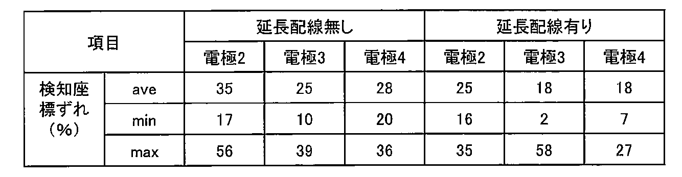
上記評価において、導電パターンを形成するための電極5間の配線は、配線幅0.8mmでは、タッチパネル31に対してタッチパネル-配線間の寄生容量により、電極5を検知するとともに配線も検知してしまい、電極5の配置座標が配線方向にずれてしまうことを確認し、また延長配線でずれを補正できることを確認出来た。これらより、電極5間の配線幅は、導電性インクの印刷可能な許容配線幅(配線抵抗が増大しない)の範囲で0.8mm以下が好ましく、0.2mm以下がより好ましい。
図5は、コード発生装置111の回路概略図である。図6(A)は、コード発生装置111を人体接触電極21に触れてタッチパネル31に接面した状態(STEP1)でタッチパネル31が検知する第1の導電パターン81を模式的に表したもの、図6(B)は、(STEP1)から、コード発生装置111の押しボタンを押圧した状態(STEP2)でタッチパネル31が検知する第2の導電パターン82を模式的に表したものである。
図2から図6に示すように、コード発生装置111は、導電パターン印刷シート400に導電性インクで印刷形成された電極5と配線を選択的にシート接続端子404および基板611の基板接続端子612(a),(b),(c)を接続することにより、第1の導電パターン81、第2の導電パターン82を導電パターン印刷シート400の印刷パターンを変更するだけで変更可能に設定出来る仕様である。
第1の導電パターン81は、導電パターン印刷シート400の電極5(511,513)から接続されたシート接続端子404と基板611の基板接続端子612(a)と(c)を接続することにより形成する。第2の導電パターン82は、導電パターン印刷シート400の電極5(512,513)から接続されたシート接続端子404と基板611の基板接続端子612(b)と(c)を接続することにより形成する。
第1の導電パターン81は、コード発生装置111のタッチパネル31に載置された状態の向きが特定可能なように3つ以上で、かつ、電極5の配置が回転対称とならない配置とし、さらにスマートフォンのマルチタッチ数の制約から5つ以下とすることが好ましい。
これにより、第1の導電パターン81のコード復号化処理結果から、接面されたコード発生装置111のタッチパネル31上の向きが特定される。このため、第2の導電パターン82は、この向きの情報を用いてコード復号化処理を行うことが出来るので、電極5の配置が回転対称となるパターンも導電パターンとして用いることが可能となる。したがって、第2の導電パターン82のコード数は飛躍的に増やすことが可能となる。
さらに、押しボタンスイッチを押圧することで(STEP1)から(STEP2)へ遷移させ、2種類のコードを時系列に発生させることが出来る仕様であるため、コード数は、第1の導電パターン81と第2の導電パターン82の掛け算となり、コード発生装置111の設定可能なコード数は飛躍的に増大する。
[実施の形態2]
図7は、実施形態12のコード発生装置112の外形を示す概略図である。図7(A)は上面図、図7(B)は、側面図、図7(C)は、底面図である。図7(D)は、垂直方向に切った断面図である。図7(A)から(D)に示すように、コード発生装置112は、実施の形態1とは、保持部204aのみ異なる構造で、本体207の部分は、実施の形態1のコード発生装置111と同一部品で構成されている。
図7は、実施形態12のコード発生装置112の外形を示す概略図である。図7(A)は上面図、図7(B)は、側面図、図7(C)は、底面図である。図7(D)は、垂直方向に切った断面図である。図7(A)から(D)に示すように、コード発生装置112は、実施の形態1とは、保持部204aのみ異なる構造で、本体207の部分は、実施の形態1のコード発生装置111と同一部品で構成されている。
コード発生装置111は、スタンプ型であり、持ち手部222を手で保持して、人体接触電極21に触れ、コード認識装置3であるスマートフォン等のタッチパネル31に接面し押圧することにより、導電パターン印刷シート400に形成した導電パターンをタッチパネル31が検知し、さらに押しボタンスイッチで導電パターンを切替え、時系列にパターンコードを発生させる使い方である。(人体導通検知)
これに対し、コード発生装置112は、平板状の保持部204aに底面4が表を向く形で本体207が取付けられた状態で使用する。図7(A)に示すように、平板状の保持部204aの四隅には、取付穴208が設けられており、取付穴208とネジで壁等に固定することも可能である。図8に示すように、コード認識装置3であるスマートフォン等を手で保持しながら、そのタッチパネル31をコード発生装置112の底面4に接面し押圧する。例えば、コード発生装置112は、博物館の展示ディスプレイ近くの壁、机等に設置し、入館者がスマートフォン等のタッチパネル31をコード発生装置112に接面することで、展示物の情報を入手したり、鉄道の駅構内の机にコード発生装置112を設置して、乗客がスマートフォン等のタッチパネル31をコード発生装置112に接面することで、スタンプラリーのポイントを入手したりするような使い方で有効である。
このとき、コード発生装置112では、人体接触電極21に指や手が触れることは無く、人体への導通無しに、導電パターン印刷シート400に形成した導電パターンをタッチパネル31に検知させる必要がある。(人体非導通検知)
また、本体207の押しボタンスイッチで導電パターンを切替え、時系列にパターンコードを発生させることが出来ることは、コード発生装置111と同じである。
図9(A)にコード発生装置111の保持部204と本体207の取付構造、図9(B)にコード発生装置112の保持部204aと本体207の取付構造を比較して示す。本体部207の上部筐体203の上面には、上面側の一部の開口が狭められた嵌合溝210が設けられており、保持部204、204aの取付面には、先端部の径が太くなった円柱状の嵌合突起209が設けられている。嵌合突起209を嵌合溝210に挿入して、保持部204ないしは本体207を回転させることで、保持部204、204aと本体207が固定され、コード発生装置111、112となる。
図10(A)、(B)に一般的な静電容量方式のタッチパネル31の電極5検知動作概略を示す。(A)がコード発生装置111をタッチパネル31に載置し、人が触った状態での検知動作(人体導通検知方式)、(B)がコード発生装置112をタッチパネル31に載置し、人が触らない状態での検知動作(人体非導通検知方式)である。
図10(A)に示すように、一般に静電容量方式のタッチパネル31は、タッチパネル表面の指でのタッチの有無と、そのタッチ位置を検知するために、タッチパネル31の内部に4mm~6mm程度の間隔で多数のTXnとRXnが垂直に交差するようにメッシュ状に配置され、TXnとRXnの交点にタッチを検知するための静電容量Cmが設けられている構造をしている。
タッチパネル31の表面に指や電極5によるTapがあると、Tap-TXn間、Tap-RXn間に静電容量が形成され、TXn-RXn間の合成容量Cm´は、Cmに対して小さくなる。多数あるTXnに対して順次数100KHz程度の電圧振幅(交流信号)を与えて、多数あるRXnに対してRXn側に流れる電流Inを測定して、Tapされている該当のTXnとRXnの交点での電流値Inの変化でCm′の容量変化を測り、Tapのタッチパネル31上の位置(座標)を特定している。
図10(A)の人体導通検知では、タッチパネル31上にコード発生装置111が載置され、導電パターン印刷シート400に印刷された直径8mm程度の電極5がタッチパネル31のいずれかの位置にTapされると、電極5により静電容量Cm´は変化する。しかし、図10(A)のTap1のように、コード発生装置111に内蔵された図示しない押しボタンスイッチで人体と切り離されている1つの電極5のみではCm´の変化量が小さく、電流I1の変化も小さいので、タッチパネル31の座標検知の判定閾値には達しない。
コード発生装置111の図示しない押しボタンスイッチを介して人体まで接続されているTap2の電極5では、人体接触電極21が人体とカップリング容量Cp2を持ちTX2の電圧振幅(交流信号)がカップリング容量Cp2を介して人体側にも微小電流を流す。このため、RX2の電流I2の変化量が大きくなり、タッチパネル31の座標検知の判定閾値を超え電極5の位置が検知される。
これに対し、図10(B)で示す人体非導通検知では、コード発生装置112で用いられる導電パターン印刷シート400に印刷された電極5は、図示しない基板611、押しボタンスイッチを介して、必ず複数の電極5が相互に接続されている。図10(B)の場合は、Tap1からTap4の電極5が接続されて、導電パターンが形成されている。また、電極5が接続されている共通ノードに後述する導電性シート211や基板611に付加される付加容量Cp2′が設けられている。
タッチパネル31が、電極5のあるTap2の位置のTX2に電圧振幅(交流信号)を与えた場合を考えると、人体非導通検知では、共通ノードを介して他のTap1、Tap3、Tap4のそれぞれの電極5がTXn、RXnとカップリング容量を持ち、TX2の電圧振幅(交流信号)がそれぞれのカップリング容量を介して、RXnに微小電流Inを流す。さらに付加容量Cp2´もカップリング容量となり、接地に微小電流を流す。
このため、RX2の電流I2の変化量が大きくなり、タッチパネル31の座標検知の判定閾値を超え電極5の位置が検知される。
また、タッチパネル31で順次TXn、RXnを切替えて、別の電極5のある位置になった場合も同様に対象TXn、RXn以外のところに位置する電極5が持つカップリング容量に微小電流を流すことが出来るので、共通ノードに接続された全ての電極5の位置をタッチパネル31に検知させることが可能である。
また、図10(B)では、電極5が全て別のTXn、RXnの上に配置された場合となっているが、実際のタッチパネル31とコード発生装置112の導電パターンは2次元(平面状)であり、複数の電極5が共通のTXnや共通のRXnの上に配置される場合がある。この時、全ての電極5がそれぞれ別のTXn、RXnの上に配置された場合に対し、実効的な容量の総計が減ってしまう場合がある。例えば、TXn、RXnおよび電極間の配線抵抗を無視すれば、2つの電極5が同じRXn上に配置された場合、2つの電極5の電極-RXn間容量CfRは、直列接続された合成容量の両側の端子が同じRXnノードに接続されたものと同様な構成となり、RXnに対して実効的に容量が見えなくなってしまう。このように、人体非導通検知では、タッチパネル31上での導電パターンの電極配置位置と電極検知性能に依存性が発生する。通常、タッチパネル31上のTXn、RXnは、四角いタッチパネル面に垂直方向、水平方向に並んでいるため、導電パターンの電極5が、タッチパネル面に垂直もしくは水平方向に複数並んだ場合、電極が検知し辛くなる。
このため、人体非導通検知のコード発生装置112では、導電パターン81、導電パターン82ともに、複数の電極5を用いた導電パターンにする必要があり、コード認識装置3のマルチタッチ数の制限数以内でより多い電極5を用いた方が、より安定に検知が可能となる。
図9(B)に示すように、コード認識装置112用本体207の上側筐体203上面には、静電容量付加用導電性シート211が上部可動電極部252と導電性シートの導電性領域が接続(導通)するよう貼り付けられる。また、静電容量付加用導電性シート211は、上側筐体203上面ではなく、平板状の保持部204aの上面側に張り付けても良い。
静電容量付加用導電性シート211は、銅フィルム等の全体が導電性を持つものでも良く、導電パターン印刷シート400と同様に導電性インクで印刷することで導電性パターンを形成したシートでも良い。導電パターンを形成する場合、配線を略12.5cmのループ状に設け、WiFiの周波数2.5GHzの電波に共振させることにより、タッチパネル31の電極検知を補助することも出来る。さらには、導電性シート211は、無くても良い。
静電容量付加用導電性シート211は、銅フィルム等の全体が導電性を持つものでも良く、導電パターン印刷シート400と同様に導電性インクで印刷することで導電性パターンを形成したシートでも良い。導電パターンを形成する場合、配線を略12.5cmのループ状に設け、WiFiの周波数2.5GHzの電波に共振させることにより、タッチパネル31の電極検知を補助することも出来る。さらには、導電性シート211は、無くても良い。
また、静電容量付加用導電性シート211の代わりに、図3(A)、(B)に示す基板611の表面裏面の配線や接点等の無いパターンの空き領域に可動電極部と接続する導電パターンを形成して付加容量としても良い。さらにまた、図4(A)に示す導電パターン印刷シート400の電極、配線の無い領域に配線として導電パターンを形成し、基板611を経由して可動電極部と接続して付加容量としても良い。
[実施の形態3]
図11は、実施の形態3のコード発生装置112aの外形を示す概略図である。図11(A)は使用状態の上面図、図11(B)は、使用状態の側面図を示す。
図11は、実施の形態3のコード発生装置112aの外形を示す概略図である。図11(A)は使用状態の上面図、図11(B)は、使用状態の側面図を示す。
コード発生装置112aは、人体非導通検知のコード発生装置112の保持部204aを変更し、人体導通検知に変更したものである。保持部204aと使用方法以外は、コード発生装置112から変更はない。
図11(A)に示すように、コード発生装置112aの保持部204bは、本体207の平面寸法よりも一方向に大きくして、コード認識装置3であるスマートフォンを底面4に接面した状態でも容易に保持部204bに触れることが出来る大きさにしたものである。保持部204bは、導電性樹脂製もしくは、樹脂表面に金属のメッキを施したもの、金属製であり導電性を有している。
保持部204bは、図示しないが、保持部204aと同様に本体部207の上部筐体203に設けられた嵌合溝210と保持部204bの取付面の嵌合突起209を嵌合し回転させることで、保持部204bと本体207を固定する構造であり、本体207と固定した時に上部筐体203に露出している上側可動接点部252と圧着し導通する。
これにより、保持部204bが人体接触電極21となり、人体導通検知方式のコード発生装置とすることが出来る。
また、図11では、右手でコード認識装置3であるスマートフォンを持ち、左手で保持部204bに触れる前提で左側方向に204bを広げているが、204bは全体に広くしても良い。
[実施の形態4]
図12は、実施の形態4のコード発生装置115の回路概略図で、(A)は、第1の導電パターン81にID切替電極514を設ける場合、(B)は、第2の導電パターン82にID切替電極514を設ける場合の回路概略図である。コード発生装置115の仕様は、コード発生装置111の仕様に対し、操作部であるID切替スイッチ95を追加し、第1、第2いずれか一方の導電パターン81、82に複数の導電パターンを設けることが可能である点が異なる。
図12は、実施の形態4のコード発生装置115の回路概略図で、(A)は、第1の導電パターン81にID切替電極514を設ける場合、(B)は、第2の導電パターン82にID切替電極514を設ける場合の回路概略図である。コード発生装置115の仕様は、コード発生装置111の仕様に対し、操作部であるID切替スイッチ95を追加し、第1、第2いずれか一方の導電パターン81、82に複数の導電パターンを設けることが可能である点が異なる。
また、ID切替スイッチ95、導電パターン切替え方法以外の部分で、実施の形態1や他の実施形態のコード発生装置から大きく変わるものではない部分の説明は省略する。
図12(A)の回路仕様では、基板611bの裏面の固定接点614と電極5の間に、SP3T型(1回路3接点)のスライドスイッチ95を設け、スイッチの各接点端子それぞれに電極514を接続する。これにより、スライドスイッチ95のポジションによりどの電極514を第1の導電パターン81で人体接触電極21まで導通させるかを切替えることが可能となり、3種類の異なった第1の導電パターン81を発生することが出来る。
図12(B)の回路仕様では、基板611cの表面の固定接点613と電極5の間に、SP3T型(1回路3接点)のスライドスイッチ95を設け、スイッチの各接点端子それぞれに電極515を接続する。これにより、スライドスイッチ95のポジションによりどの電極515を第2の導電パターン82で人体接触電極21まで導通させるかを切替えることが可能となり、3種類の異なった第2の導電パターン82を発生することが出来る。
図13は、コード発生装置115の外形を示す概略図である。図13(A)は上面図、図13(B)は、側面図である。図13(C)は、垂直方向に切った断面図である。図13(A)から(C)に示すように、コード発生装置115は、実施の形態1で示すコード発生装置111と同様に四角いスタンプに似た形状としており、筐体2上部が操作部6の押しボタンスイッチの押しボタンとなっているため、筐体2を手で持ってタッチパネル31に接面し、押圧することで第1の導電パターン81、第2の導電パターン82の2種類のパターンコードを順次発生させることができ、さらに、ID切替スイッチ95が設けられているため、第1の導電パターン81もしくは、第2の導電パターン82の何れか一方の導電パターンを複数設けることが可能な仕様となっている。
図13(A)から(C)に示すように、上側筐体203および保持部204にそれぞれ開口部231、241が設けてあり、開口部241からコード切替用スイッチ操作部951が切替操作可能な程度突出している。筐体2上面の開口部241のコード切替用スイッチ操作部951が摺動する方向に沿った辺には、スライドスイッチの各切替りポジション位置に対応した部分に導電パターンのコードに対応したマーク242が設けられている。マーク242は、図63(A)では、数字とポジションを示す△印を保持部204の上面に浅く彫り込む形状で形成されている。また、マーク242は、これに限定されるものでは無く、凸状に設けても良く、印刷やシールを貼りつけることで形成しても良い。さらに、マーク242は、数字に限らず、使用状況に対応したグラフィック等にしても良い。
保持部204に設けられた開口部241は、コード切替用スイッチ操作部951が摺動する方向に沿った長方形の開口部分に加え、保持部204の中心方向左回りに略弧状に広がっている。これは、コード発生装置115に於いても実施の形態1のコード発生装置111と同様に、図9に示される保持部204と上部筐体203を回転させて固定する機構を設けているためである。
また、上部筐体203に設けられた開口部231は、操作部6の押しボタンスイッチを切替えるため持ち手222を押下した時に、スライドスイッチ95のボディ部分と上部筐体203が接触しない程度の大きさで開口している。
また、図12(A),(B)に対応する2種類の回路仕様は、パターン配線のみ異なる基板611b、611cを交換するだけで変更可能であり、基板以外の全ての部品は、両方の回路仕様で共通に使用することが出来る。
[実施の形態5]
<切替え可能な導電パターンとパターンコード復号化方法>
導電パターンを切替可能なコード発生装置1では、コード発生装置1全体で発行可能なコード数を多くするため、および、パターンコードへの復号化を容易にするために、(STEP1)の第1の導電パターン81および(STEP2)の第2の導電パターン82のそれぞれの電極配置方法に条件を設け、その電極配置条件を加味したパターンコード化処理を行う必要がある。以下に、切替え可能な導電パターンとパターンコード復号化方法の1例を示す。
<切替え可能な導電パターンとパターンコード復号化方法>
導電パターンを切替可能なコード発生装置1では、コード発生装置1全体で発行可能なコード数を多くするため、および、パターンコードへの復号化を容易にするために、(STEP1)の第1の導電パターン81および(STEP2)の第2の導電パターン82のそれぞれの電極配置方法に条件を設け、その電極配置条件を加味したパターンコード化処理を行う必要がある。以下に、切替え可能な導電パターンとパターンコード復号化方法の1例を示す。
図14は、パターンコード化のための電極検知座標の(STEP1)と(STEP2)の判定方法の説明図で、(A)が(STEP1)の状態、(B)が(STEP2)の状態である。図15は、パターンコード化のための座標変換方法を示す図で、(A)がタッチパネル31の検知座標系の検知状態を示す図であり、(B)が(STEP1)の検知状態をコード発生装置1の電極配置グリッド座標系に変換した状態であり、(C)が(STEP2)の検知状態をコード発生装置1の電極配置グリッド座標系に変換した状態である。図16は、操作部6を有し、第1の導電パターン81と第2の導電パターン82を切替可能なコード発生装置1のパターンコード化処理の一例を示すフローチャート図である。
導電パターンを切替可能なコード発生装置1では、操作部6であるところの例えば、押しボタンスイッチ60を押下することで、押下前の(STEP1)の状態と押下後の(STEP2)の状態で、それぞれ第1の導電パターン81と第2の導電パターン82として設けられている複数の電極5を人体接触導電材21と接続するか遮断するかを切替えることで、2通りのコードを発生することが出来る仕様である。
≪導電パターン電極配置仕様≫
図15(B)に第1の導電パターン81の電極配置例、(C)に第2の導電パターン82の電極配置例を示す。電極5は、タッチパネル31に接面するコード発生装置1の底面4の領域にX,Yの電極配置グリッド座標系を設け、その整数座標点に配置する。これにより、各電極5の配置間隔は、グリッド座標系の単位グリッド間隔から容易に計算可能となる。単位グリッド間隔は、使用が想定されるタッチパネル31のサイズやタッチパネルの座標検知位置精度、コード発生装置1の底面4のサイズ、電極5のサイズ等から設定する。本実施例の場合、底面4の領域をX,Y共に0から6に分割する座標系とした。
図15(B)に第1の導電パターン81の電極配置例、(C)に第2の導電パターン82の電極配置例を示す。電極5は、タッチパネル31に接面するコード発生装置1の底面4の領域にX,Yの電極配置グリッド座標系を設け、その整数座標点に配置する。これにより、各電極5の配置間隔は、グリッド座標系の単位グリッド間隔から容易に計算可能となる。単位グリッド間隔は、使用が想定されるタッチパネル31のサイズやタッチパネルの座標検知位置精度、コード発生装置1の底面4のサイズ、電極5のサイズ等から設定する。本実施例の場合、底面4の領域をX,Y共に0から6に分割する座標系とした。
また、各導電パターン内の電極5の配置は、全ての整数座標点に配置出来るわけでは無く、各電極5の間隔や、配置位置への制約は、電極5のサイズ、導電パターンとして複数の電極5を近い座標位置に配置した場合のタッチパネル31の検知座標への影響等を考慮して決定する。例えば、電極間隔の最小値は、2個の電極5がタッチパネル31上で1個の電極として検知されない距離以上とすることが必要である。
また、特にスマートフォンで多く用いられる投影型静電容量タッチパネルの場合、タッチパネルの外枠に平行に電極が複数並ぶと、タッチパネル内の座標検知用透明電極の1ラインに複数のコード発生装置の電極5が並んでしまうため、タッチパネル31の検知に影響を与える場合がある。このため、導電パターン内で電極5が同一線上に並ぶ数に制限を加えても良い。
また、特にスマートフォンで多く用いられる投影型静電容量タッチパネルの場合、タッチパネルの外枠に平行に電極が複数並ぶと、タッチパネル内の座標検知用透明電極の1ラインに複数のコード発生装置の電極5が並んでしまうため、タッチパネル31の検知に影響を与える場合がある。このため、導電パターン内で電極5が同一線上に並ぶ数に制限を加えても良い。
第1の導電パターン81では、コード発生装置1がタッチパネル31に載置された向きが特定できるようにするため、最低3個の電極5が検知される必要があり、また、コード認識装置3として想定されるスマートフォンのマルチタッチ数制約を考慮すると、最高5個の電極数が好ましい。このため、本実施例では、第1の導電パターン81で4個の電極5を設けた。
ただし、コード発生装置1のタッチパネル31接面の方向を固定する使用方法とした場合や、マルチタッチ数制約が無いもしくは5個以上のタブレットや、専用の業務用機器をコード認識装置3とする場合は、電極数の最小数、最大数は、前記数に制約されない。
ただし、コード発生装置1のタッチパネル31接面の方向を固定する使用方法とした場合や、マルチタッチ数制約が無いもしくは5個以上のタブレットや、専用の業務用機器をコード認識装置3とする場合は、電極数の最小数、最大数は、前記数に制約されない。
第1の導電パターン81では、コード復号化を容易にするために、基準となる電極を設けることが好ましい。本実施例では、電極間距離が最長となるグリッド座標系(0,0)、(6,6)の位置の2電極を基準電極として、全ての第1の導電パターン81に設けた。これにより、基準電極間の長さLmaxと、基準電極間を結んだ線分とグリッド座標系のX軸とのなす角θ1をコード復号化に活用できる。また、基準電極位置は、本実施例の座標に限定されるわけでは無く、基準電極間距離と基準電極間を結んだ線分とグリッド座標系のX軸とのなす角が特定できるものであれば良い。
例えば、本実施例でも(0,0)、(5,6)の2点に基準電極を設けることも可能であり、コード復号化処理アルゴリズムをその基準電極位置に対応させたものにすることに依って、別のコード体系の導電パターンを多数設定出来る。例えば、実施例の(0,0)、(6,6)の2点を基準電極としたコード体系と、(0,0)、(5,6)の2点を基準点としたコード体系、さらには、別の2点を基準点としたコード体系というように、複数のコード体系のそれぞれに対応した導電パターンとコード復号化処理アルゴリズムを準備して置けば、コード発生装置1の本体部分を変更することなく、システム全体としてより多くコードを発行できる。
第2の導電パターン82では、切替可能なコード発生装置1の特徴より、(STEP1)の第1の導電パターン81と(STEP2)の第2の導電パターン82の両方の電極配置座標の情報をコード復号化に活用できるため、基準電極は不要である。このため、第2の導電パターン82は、電極5の間隔や配置の制約のみに従って、配置座標に自由に電極5を配置することが出来る。
また、配置電極数も1個以上、マルチタッチ数制約数の範囲で自由に配置可能である。このため、第2の導電パターン82は、より多くの導電パターンを設定出来る。本実施例では、第2の導電パターン82に1個から4個の電極を配置する構成とした。
また、配置電極数も1個以上、マルチタッチ数制約数の範囲で自由に配置可能である。このため、第2の導電パターン82は、より多くの導電パターンを設定出来る。本実施例では、第2の導電パターン82に1個から4個の電極を配置する構成とした。
第2の導電パターン82では、さらに、切替可能なコード発生装置1の特徴より、第1の導電パターン81に配置した電極5の配置座標と同一座標に第2の導電パターン82の電極5を配置することも可能である。例えば、導電パターン印刷シート400を用いる構成の導電パターンを切替可能なコード発生装置1では、第1、第2の導電パターン81,82の電極5を同一の座標に配置した場合、導電パターン印刷シート400に印刷される電極の数が、(STEP1)、(STEP2)で合わせて使用する電極数よりも少なくなり、2種類の導電パターンの電極5の配置が容易になり、多数の導電パターンを設定可能になる。
また、本実施例では、第1の導電パターン81に基準電極を設け、かつ電極5を3個以上とし、第1の導電パターン81でタッチパネル31に載置された向きを特定できるようにし、第2の導電パターン82の方には基準電極を設けない構成としたが、基準電極を第2の導電パターン82の方に設け、かつ電極5を3個以上とし、第2の導電パターン81でタッチパネル31に載置された向きを特定できるようにし、第1の導電パターン81には基準電極を設けない構成とすることも可能である。この後者の構成の仕様も別に設ければ、さらにコード発生装置1の本体部分を変更することなく、システム全体としてより多くコードを発行できるようになる。
さらにまた、第1の導電パターン81と第2の導電パターン82の両方のパターンを合わせて一組の基準電極を設けることも出来る。例えば、(0,0)の位置の基準電極を第1の導電パターン81に設け、(6,6)の位置の基準電極を第2の導電パターン82の方に設けることにより、最も長い電極間距離を第1、第2の導電パターン間81,82の電極5の間で形成し、さらに第1、第2の導電パターン81、82のどちらかの基準電極以外の電極5を用いて、タッチパネル31に載置された向きを特定できるようにすることも可能である。これにより、第1、第2導電パターン81、82共に自由に配置出来る電極数が増えるので、より多くの導電パターンを設けることができ、システム全体としてより多くコードを発行できるようになる。
これらの仕様に基づいて作成した第1の導電パターン81、第2の導電パターン82の各電極配置座標値をまとめたものを、(STEP1)用、(STEP2)用基準化座標パターンコードとして基準化座標パターンコードテーブルを作成する。
≪パターンコード復号化方法≫
導電パターンを切替可能なコード発生装置1では、(STEP1)の第1の導電パターン81および、(STEP2)の第2の導電パターン82が設けられ、操作部6である押しボタンスイッチ60の押下により、それぞれで複数配置された電極5を人体接触導電材21と接続するか遮断するかを切替えることで、2通りのコードを発生することが出来る仕様である。
導電パターンを切替可能なコード発生装置1では、(STEP1)の第1の導電パターン81および、(STEP2)の第2の導電パターン82が設けられ、操作部6である押しボタンスイッチ60の押下により、それぞれで複数配置された電極5を人体接触導電材21と接続するか遮断するかを切替えることで、2通りのコードを発生することが出来る仕様である。
このため、一般的なコード復号化処理の前段階として、タッチパネル31に検知された電極座標情報が(STEP1)の第1の導電パターン81のものであるのか、(STEP2)の第2の導電パターン82のものであるのかを判別する必要がある。
2種類の導電パターンを設けるため、コード発生装置1の底面4には、それぞれの導電パターン81、82において、それぞれの導電パターン81、82の電極配置では必要ない電極5が、人体接触導電材21と接続されない状態で、コード認識装置3である例えばスマートフォンのタッチパネル31上に存在している。
また、スマートフォン3のタッチパネル31のタッチ位置検知アルゴリズムでは、指のタッチを継続的に、同一のタッチであると認識させるために、一度検知したタッチ位置の検知感度の閾値を低下させる制御(検知閾値のヒステリシス制御)を行っているものがあり、この検知閾値のヒステリシス制御で閾値低下幅が大きい設定の一部のスマートフォンでは、(STEP1)の第1の導電パターン81で人体接触導電材21と接続された電極5が、(STEP2)の第2の導電パターン82で人体接触導電材21から遮断されたにも関わらずタッチパネル31に検知され続けてしまう場合があり、(STEP2)の第2の導電パターン82が正しくコード認識出来ない問題が発生する。
これら2つの課題に対応するパターンコード復号化方法の例を示す。
本実施例の導電パターンの電極配置仕様は、以下の4条件に従っている。(1)第1の導電パターン81で基準電極2個を含む4個の電極5を用いる。(2)第2の導電パターン82では、1個から4個の電極5を用いる。さらに、(3)第2の導電パターン82の電極配置では、第1の導電パターン81の電極配置位置には配置しない、(4)第2の導電パターン82の電極間距離が、基準電極間の長さLmaxより小さい値となるようにする。
図16(A)に検知座標判定の前処理フローを、図14(A)(B)にタッチパネル座標系での(STEP1)、(STEP2)での電極検知状態の例を示す。図16(A)に示すように、タッチパネル31にコード発生装置を載置すると、(STEP1)となり、S1の状態で、タッチパネル31が4点の座標を検知する。この検知座標を基に、コード認識装置の4点の内の2点間の距離を全て計算し、最長の電極間距離L1pmaxを求めると共に、押下前の(STEP1)の4点の電極座標として、P11からP14を記憶する。
次に、S2の状態で、L1pmaxを基準電極間の電極配置グリッド数(本実施例では、6)で割り、タッチパネル上の座標系での検知座標許容誤差範囲長L1pmを求める。図14(A)は、タッチパネルが(STEP1)で4点P11からP14を検知した状態の例で、検知座標P11-P14間の距離が最長でL1pmaxとなり、それぞれの検知座標位置に破線でしめされた半径L1pm/2の同心円の内部が検知座標許容誤差範囲であることを示している。
また、S2の状態からさらにタッチパネルが新たな4点の座標を検知した場合、S3の状態となり、4点の内の2点間の距離を全て計算し、最長の電極間距離L1pmax´を求め、値が記憶しているL1pmaxに対し±L1pm/2の範囲の場合、(STEP1)の4点の電極座標P11からP14を更新し、S2を再度行う。
次に、図16(A)に示すように、記憶しているP11からP14の検知座標に対し、座標の同心円L1pm/2の範囲外の座標が新たにタッチパネルから1点以上確認検知された場合、S4の状態として、タイマーをスタートさせ、押下後の(STEP2)遷移時間tt12を測定する。遷移時間tt12測定中は、S1の状態で待機する。
タイマーが所定の遷移時間tt12を経過した時点でS5の状態となり、その時点の検知電極座標P21からP2nの座標値に対し、記憶しているP11からP14までの座標情報と比較し、P11からP14 の座標の同心円L1pm/2の範囲外の座標のみを残し、残った検知電極数mと検知座標P21からP2mを押下後の(STEP2)の検知座標として記憶する。
図14(B)は、タイマースタート後tt12時間経過後に(STEP2)として、P21とP22、およびP12aの電極検知座標が得られた場合の例であり、P21とP22は、記憶しているP11からP14の検知座標の同心円L1pm/2の範囲外のため、(STEP2)の第2の導電パターン82の検知電極座標として記憶する。P12aは、記憶しているP12の検知座標の同心円L1pm/2の範囲内のめ、検知閾値のヒステリシス制御の影響による第1の導電パターン81の電極5の検知残りと判断し、第2導電パターン82の検知電極座標からは、削除される。
第2導電パターン82の検知電極座標が得られた時点で、S6の状態となり、(STEP1)の検知座標P11からP14と、(STEP2)の検知電極数m、検知座標P21からP2mを合わせて、復号化フローへ送り、前処理を終了する。
次に、(STEP1)、(STEP2)の検知座標情報が揃ったら、コード復号化フローを実行する。図16(B)に検知座標判定のコード復号化フローを、図15(A)タッチパネル座標系での(STEP1)の電極検知状態を(B)、(C)配置グリッド座標系へ変換後の(STEP1)、(STEP2)での電極検知状態の例を示す。
図16(B)に示すように、初めに、(STEP1)の検知した4点の検知座標内の2点間の距離を全て計算し、長い順にソーティングして、長い順にL1からL6を求める。次に、最長線分L1を構成する始点PSと終点PEを求め、タッチパネルの検知座標系のX´軸方向に対する2点PS,PEを結ぶ線分の角度θ0を求める。(状態E1、E2)
図15(A)は、(STEP1)でP11からP14の4点の電極座標を検知し、各2電極間の距離を求め、最長線分L1がP11―P14間であり、PSをP11、PEをP14とし、X´軸とのなす角がθ0の場合の例である。
図15(A)は、(STEP1)でP11からP14の4点の電極座標を検知し、各2電極間の距離を求め、最長線分L1がP11―P14間であり、PSをP11、PEをP14とし、X´軸とのなす角がθ0の場合の例である。
ここで、基準電極P11とP14が配置グリッド座標のX軸となす角θ1は、判っているので、θ0からθ1を引くことでタッチパネル検知座標系に対する配置グリッド座標系の回転角θ´が判る。また、同様に基準電極P11とP14を結ぶ線分の長さも判っているので、最長線分L1との比をとることで、タッチパネル検知座標系に対する配置グリッド座標系の拡大縮小比率が判る。
これらの情報より、PSを原点とし、タッチパネル上の座標値を-θ’回転させ、拡大縮小比率をかけることで、電極配置のための配置グリッド座標系に座標変換する。図15(B)は、導電パターン81のP11基準電極の配置グリッド座標よりタッチパネル検知座標P11をPSとして、(STEP1)のP11からP14を配置グリッド座標系に変換した場合の例であり、図15(C)は、(STEP2)のP21からP22を配置グリッド座標系に変換した場合の例である。
(STEP1)、(STEP2)全ての検知座標を座標変換し、変換後の各検知点の座標値が検知座標許容誤差の範囲内で一致するかをそれぞれの基準化座標パターンコードテーブルの座標値と照合する。照合の結果、一致するものが無い場合、始点PSと終点PEを交換して状態E2から再度実行する。(図16(B)の状態E3,E4)
得られた座標値から(STEP1)、(STEP2)の各IDコードを特定し、それらをつなぎ合わせたコード発生装置としてのIDコードを特定し、対応する処理を実行することで、コード復号化処理は完了する。(図16(B)の状態E3,E4)
また、本実施例では、コード発生装置1をタッチパネル31に接面させる時に、任意の角度で接面してもコードを認識出来るような構成としたが、コード復号化処理の過程で得られるタッチパネル31の検知座標系と配置グリッド座標系の回転角を用いて、タッチパネル31とコード発生装置3の接面時の回転角に応じた処理を実行させることも可能である。例えば、タッチパネル31の1辺に対して、略正方形の底面形状のコード発生装置1の4つの各辺を対応させて、すなわち、コード復号化処理の回転角0、90、180、270度の4状態に対応させて1つのコード発生装置1で、4種類の処理を行うことも出来る。
さらに、パターンコード復号化処理の図16(A)に示す前処理フロー部分をコード認識装置3であるスマートフォンに、アプリケーションプログラムもしくは、ウェブブラウザのプログラムとして設け、図16(B)に示すコード復号化フロー部分をサーバに設け、スマートフォンから通信により前処理された電極検知座標情報をサーバに送り、サーバでコード復号化したIDコードをスマートフォンに返すようにすることも出来る。これにより、コード復号化処理方法と基準化座標パターンコードテーブルの秘匿性を高めることが可能となる。
本実施例の導電パターン仕様とパターンコード復号化方法は、これに限定されるわけでは無く、言うまでもないが、導電パターン仕様に基づいて作成したパターンコードがコード復号化処理によりパターンコードテーブルにあるコードと一致/不一致の判定が可能であれば、どのようにコード復号化処理を行っても構わない。
[実施の形態6]
図17(A)は、コード発生装置117の外観の一例を示す側面模式図であり、(B)は、上面模式図、(C)は、底面模式図である。図18は、コード発生装置117の構成概略図である。図19は、コード発生装置117の側面を垂直方向に切った断面概略図である。コード発生装置117は、コード認識装置3であるスマートフォンのタッチパネル31に、押しボタンスイッチで電極5を検知させたことをトリガにしてスマートフォンとコード発生装置117を1対1の通信で接続し、コードパターンや他の多くの情報を送受信するものである。
図17(A)は、コード発生装置117の外観の一例を示す側面模式図であり、(B)は、上面模式図、(C)は、底面模式図である。図18は、コード発生装置117の構成概略図である。図19は、コード発生装置117の側面を垂直方向に切った断面概略図である。コード発生装置117は、コード認識装置3であるスマートフォンのタッチパネル31に、押しボタンスイッチで電極5を検知させたことをトリガにしてスマートフォンとコード発生装置117を1対1の通信で接続し、コードパターンや他の多くの情報を送受信するものである。
図17(A)(B)に示す様に、コード発生装置117は、四角いスタンプに似た形状としており、筐体2の上部が押しボタンスイッチ60となっており、さらに押しボタンは導電性を持たせ、人体接触導電材21としている。また、側面には、電池交換時に開け閉めする電池ケース扉260、USBコネクタ261が設けられている。また、(C)に示すように、底面4には、隣接した電極5が同時にタッチパネル31に接面しても1つの電極として検知されない間隔を開けて複数配置されている。図では、電極5が示されているが、底面4には、電極5の静電容量を大幅に低減させない程度に薄く有色の樹脂製のシートや薄板410で覆われている。
電極54、56の3個の電極配置は、コードパターンとして他と区別できる配置であり、さらに、例えば、直角三角形の様な人の指がタッチパネル31にタッチする場合に、容易に同じ形状をタッチすることが困難な配置にすることが好ましい。また、電極部560に設ける電極数を4もしくは、5と増やすことで、人の指がタッチパネル31に容易に同じ形状をタッチすることが困難になるようにしても良い。
電極54、56の3個の電極配置は、コードパターンとして他と区別できる配置であり、さらに、例えば、直角三角形の様な人の指がタッチパネル31にタッチする場合に、容易に同じ形状をタッチすることが困難な配置にすることが好ましい。また、電極部560に設ける電極数を4もしくは、5と増やすことで、人の指がタッチパネル31に容易に同じ形状をタッチすることが困難になるようにしても良い。
図18および図19に示す様に、コード発生装置117には、底面4に電極5のある電極部560、筐体2内のPCB基板728に搭載された制御部720、押しボタンスイッチ60の操作部6がある。
電極部560には、人体接触導電材21と直接つながる電極54が2個設けられており、さらに、押しボタンスイッチ60を介して人体接触導電材21と接続するトリガ電極56が1個設けられている。
電極部560には、人体接触導電材21と直接つながる電極54が2個設けられており、さらに、押しボタンスイッチ60を介して人体接触導電材21と接続するトリガ電極56が1個設けられている。
筐体2の中には、PCB基板728に実装された制御部720があり、制御部720には、情報処理装置として、CPU(Central Processing Unit)721と、内部メモリのRAM(Random Access Memory)722 と、ROM(Read Only memory)723、無線通信部724、GPS(Global Positioning System)受信部725、USB(Universal Serial Bus)制御部726、電源部727とを備えている。さらに、操作部6には、押しボタンスイッチ60が、押しボタンが人体接触導電材21と一体となって設けられている。電源部727と操作部6以外のこれらは、1つの半導体デバイスで構成されていても良く、または、複数の半導体デバイスを組み合わせて構成することも可能である。
CPU721、RAM722、ROM722は、情報処理装置を構成し、押しボタンスイッチ60が押下によりオンした時に、電源が投入され、ROM722より必要なデータを読み込み、対応した処理を行う。ROM723には、コード発生装置117の個々に対応したID番号、押しボタンスイッチ60が押下された時にスマートフォンに送る情報等が記憶されている。また、無線通信部724には、無線LAN(ローカルエリアネットワーク)を構築することが可能なWiFi、ブルートゥース(登録商標)等の無線デバイスが用いられている。GPS受信部725は、当該のコード発生装置117がある場所の位置情報を入手するものである。USB制御部726は、コード発生装置117のプログラム更新、データ入出力、充電等時が行われる際に、図示しない他の装置とのUSB接続を制御するものである。また、USB制御部726は、無くても良い。電源部727は、制御部720に電力を供給するもので、制御部720に搭載される回路、デバイスの仕様に合った電力を供給できれば、乾電池、充電池のいずれでもよい。充電池とするならば、USBコネクタ261から充電出来るようにすることも可能である。
また、コード認識装置3には、コード発生装置117の電極5をタッチパネル31が検知したときに、検知座標から、コード発生装置117を認識し、無線LANを構築するアプリケーションプログラムが実装されている。
本実施例に基づいてコード発生装置の動作および処理を説明する。(1)コード発生装置117がコード認識装置3のタッチパネル31に接面され、人の指が人体接触導電材21に触れると、2個の基準電極54がタッチパネル31に検知される。(2)さらに、押しボタンスイッチ60を押下すると人体接触導電材21とトリガ電極56が導通し、タッチパネル31に検知される。(3)コード発生装置117は、さらに制御部720を起動し、所定の時間内に、情報処理装置により無線LANを構築するための接続要求をコード認識装置3に送る。(4)3個の検知座標が得られるとコード認識装置3は、アプリケーションプログラムで、検知座標を解析しトリガ情報の3点かどうかを判定する。トリガ情報の場合、無線LANを起動し、接続を受け入れる状態となり、所定の時間までに接続の要求があった装置が、当該のコード発生装置117と判断して、接続する。(5)コード発生装置117とコード認識装置3が無線LANにて接続されると、コード発生装置117は、情報処理装置によりROM723に書き込まれているID番号をコード認識装置3に送る。コード認識装置3には、受け取ったID番号を照合し、接続が正しいかを判定する。接続が正しければ、その他の必要な情報の送受信を行う。
タッチパネル31の電極検知座標は、通信の起動トリガに使われ、ID番号や他の情報は通信で行うことにより、沢山の情報をやり取りできるようになる。ID番号は、ROMに書き込まれるため、必要な数だけ容易に作成出来る。
図20(A)は、実施の形態6の変形例であるコード発生装置117aの外観の一例を示す側面模式図であり、(B)は、上面模式図、(C)は、底面模式図であり、(D)は、構成概略図である。
図20(C)(D)に示すように、コード発生装置117aは、コード発生装置117の底面4にドットコード読み取り装置730を設け、制御部720にドットコード読み取り部732を設けたものである。底面4に設けられているシートもしくは薄板410は、ドットコード読み取り装置730の部分は、開口している。
図20(A)に示すように、筐体2の側面にドットコード読み取りスイッチ731を設け、ドットコード読み取りスイッチ731をオンさせると、タッチパネル31もしくは他の媒体に表示されたドットコードを読み取り、制御部720のRAM722もしくはROM723に記憶できる。
ドットコード読み取り装置730を設けることにより、事前にROM723に入力した情報だけでなく、別途ドットコードで他の情報を準備することで、コード発生装置117aを用いてコード認識装置3であるスマートフォンに送信することが可能となる。
図21(A)は、実施の形態6の変形例であるコード発生装置117bの外観の一例を示す側面模式図であり、(B)は、上面模式図、(C)は、底面模式図であり、(D)は、構成概略図である。
図21(C)(D)に示すように、コード発生装置117bは、コード発生装置117の底面4にフォトダイオード740を設け、制御部720に光変換処理部742を設けたものである。底面4に設けられているシートもしくは薄板410は、フォトダイオード740の部分は、開口している。また、無線通信部724の代わりに光変換処理部742を設ける構成にしても良い。
図21(A)に示すように、筐体2の側面に受信スイッチ741を設け、受信スイッチ741をオンさせると、タッチパネル31に表示された光コードを読み取り、制御部720の光変換処理部742でコード変換処理し、RAM722もしくはROM723に記憶できる。
また、無線通信部724の代わりに光変換処理部742を設けた場合、タッチパネル31にコード発生装置117bを接面し押しボタンスイッチ60を押下すると、電極座標情報がコード認識装置3でコード認識、照合し正しいIDの場合、コード発生装置117bのフォトダイオード740に対応した領域のタッチパネル31の光度を変更してID確認の光データパターンを発行、コード発生装置117bのフォトダイオード740が受光して光変換処理部742が、IDが確認されたことを確認出来る。
フォトダイオード740を設けることにより、コード認識装置3であるスマートフォンから、無線を使わずに、コード発生装置117bが情報を受け取ることが出来る。
コード発生装置117、117a、117bに設けられた制御部720の各機能は、組み合わせて用いることも可能であり、また、必要のない機能は外した構成とすることも可能である。また、言うまでもないが、これらのコード発生装置117、117a、117bに設けられた制御部720を設ける方式は、他の実施の形態のコード発生装置に用いることも可能である。
[実施の形態7]
次に、図22~図28を参照して、コード発生装置による種々のシステムについて説明する。
次に、図22~図28を参照して、コード発生装置による種々のシステムについて説明する。
(企業ID・スタンプコード認証システム)
図22は、コード発生装置の1種である電子スタンプの操作部の設定の実施例であるスライドスイッチにより、スタンプコードを複数設定できるマルチコードスタンプのコード仕様を示している。本実施例は、スライドスイッチによりスタンプコードを発行する電子スタンプであるが、スタンプやスライドスイッチに拘らずどのような形状・形態であってもよい。
図22は、コード発生装置の1種である電子スタンプの操作部の設定の実施例であるスライドスイッチにより、スタンプコードを複数設定できるマルチコードスタンプのコード仕様を示している。本実施例は、スライドスイッチによりスタンプコードを発行する電子スタンプであるが、スタンプやスライドスイッチに拘らずどのような形状・形態であってもよい。
図22(A)の操作部であるスライドスイッチは、「1」、「2」、「3」のスライドスイッチポジションに切り替えられるようになっている。図22(B)で示すように「1」のスライドスイッチポジションでは選択電極1、「2」のスライドスイッチポジションでは選択電極2、「3」のスライドスイッチポジションでは選択電極3にそれぞれ導通され、第1の導電パターンが形成される。この実施例では、第1の導電パターンの内、いずれの選択電極も含まない導電パターンがスタンプID:150を示している。ここで、いずれかの選択電極が導通された場合、選択電極1ではスタンプコード:1501、選択電極2ではスタンプコード:1502、選択電極3ではスタンプコード:1503としている。図82では、選択電極1、2,3をそれぞれ含むスタンプコードは、A, B, Cに対応している。
ユーザが電子スタンプを使用する際に、課金の実施や利用ログの取得、電子スタンプが発行するスタンプコードの解析の秘匿を実施するには、スタンプID認証システムを構築するのが望ましい。認証システムのフローを図23に示す。
(1)まず、契約企業の企業IDと、当該企業が使用する1以上のスタンプIDを認証サーバーに登録する。企業ID-スタンプIDテーブルを作成してもよい。図示しないが、マルチコードスタンプで複数発行できるスタンプコードをスタンプIDに代えて認証サーバーに登録してもよい。もちろん、スタンプIDとスタンプコードの両方を登録してもよい。
(2)次に、QRコードの読取やアプリ実行等、情報処理装置により所定の処理が行われると、タッチパネルに電子スタンプの押印を誘導するタッチ画像が表示される。
(3)次に、ユーザは、タッチパネルに表示されたタッチ画像に電子スタンプを保持して押印する。
(4)次に、電子スタンプが翳されたタッチパネルは、検出された静電容量から所定数の電極の座標位置(座標値)を検知する。
(5)次に、タッチパネルに接続された情報処理装置(ソフトウェアを含む)は、少なくとも当該座標値と企業IDを認証サーバーに送信する。ここで、図示しないが、情報処理装置において、当該座標値からパターン解析によりスタンプコードを認識し、スタンプコードからスタンプIDを取得する機能を備えてもよい。なお、スタンプコードのみ認識して、スタンプコードからスタンプIDを取得する機能は認証サーバーにおいてもよい。これにより、どのスタンプコードがどのスタンプIDに属するかを秘匿することができる。
(6)次に、認証サーバーは、受信した電極の座標値からパターン解析によりスタンプコードを認識し、スタンプコードからスタンプIDを取得する。なお、当該電子スタンプがマルチコード発行機能を有さない場合、スタンプコードはスタンプ毎に1種であり、スタンプIDと同一となる。(5)で当該座標値からパターン解析によりスタンプコードを認識し、スタンプコードからスタンプIDを取得した場合は、認証サーバーは、当該スタンプコードおよびスタンプIDを受信してもよいし、スタンプコードのみ受信し認証サーバーでスタンプコードが属するスタンプIDを取得してもよい。
(7)次に、認証サーバーは、取得したスタンプIDまたはスタンプコードが企業IDと共に登録されたコードであるかどうかを照合する。
(8)認証サーバーは、取得したスタンプコードが予め登録されたスタンプコードとして照合された場合は、情報処理装置(ソフトウェアを含む)にスタンプコードを送信し認証を完了する。照合されなかった場合は、認証サーバーは、エラーを示すコードを情報処理装置(ソフトウェアを含む)に送信し、非認証となる。非認証となった場合は、登録されていないスタンプコードの電子スタンプを使用しているため、当該電子スタンプに対応する(2)から再実施する必要がある。
(9)情報処理装置(ソフトウェアを含む)は、認証されたスタンプコードにより、WEBサイト等のコンテンツの閲覧や様々な情報処理を実行する。
なお、(1)では、スタンプIDの代わりに、スタンプIDに対応する所定数のスタンプコードを登録してもよい。その場合、(5)で企業IDと共に登録された所定数のスタンプコードを照合する。スタンプID認証システムでは、認証した企業IDやスタンプコードの履歴を時間と共に記録することができ、電子スタンプの効果測定やマーケッティングリサーチに活用できる。スマートフォン等の情報処理装置に内蔵されたGPSと連動させれば、利用地域と共に履歴を記録することができる。電子スタンプを使用したスタンプラリーでは、当該電子スタンプがどこに設置されているかの位置情報を認証サーバーに登録し、スマートフォンからの送信情報に位置情報を含めれば、スタンプのID数に限界があっても、スタンプIDと位置情報によって確実にスタンプを特定することができる。また、店舗にてスタンプやクーポン、ポイント付与・消し込みにおいても同様なシステムを提供できる。さらに、あり得ない位置情報でスタンプを使用していることが判明すると、スタンプが偽造・盗品であることも確認できる。また、各ユーザに電子スタンプを渡し各ユーザのスマートフォンにスタンプIDを記録し、当該スマートフォンIDとスタンプIDを認証サーバーに登録する。そして、予め認証サーバーに登録された所定の場所に設置されたタッチパネル(スマートフォンやタブレットを含む)に電子スタンプを押印すれば、タッチパネルに接続された認証サーバーから、認証されたユーザのスマートフォンにスタンプ押印履歴を送信し、対応するサービスを提供することもできる。
電子スタンプ使用による様々な課金の実施には、PINコード入力やパスワードを併用して、スタンプコード認証に合わせて高いセキュリティを確保できる。このPINコードやパスワード入力には、アプリにスタンプの回転角検知機能を備えれば、スタンプの正の方向に▲等のマークを設け、スタンプを載置した際の載置する方向の順番をパスワードとして設定することができる。本発明のコード発生装置は、タッチパネルに物理量を検出させ複数の座標情報を取得し、タッチパネルに内蔵または接続された情報処理装置で、複数の座標情報からパターン解析し、コード発生装置から発生されたコードを認識させるだけでなく、同時にパターンの方向すなわちコード発生装置の方向も計算される。そこで、スタンプはどのような方向でタッチパネルに載置しても、スタンプコードとスタンプの向きを認識することができる。その精度は、±数度以内であり、人の操作性を勘案しても、縦横・斜め方向の計8方向までは、確実に認識できることから、上方向(0度):337.5度<θ1≦22.5度、斜め右上方向(45度):22.5度<θ2≦67.5度、右方向(90度):67.5度<θ3≦112.5度、斜め右下方向(135度):112.5度<θ4≦157.5度、下方向(180度):157.5度<θ5≦202.5度、斜め左下方向(225度):202.5度<θ6≦247.5度、左方向(270度):247.5度<θ7≦292.5度、斜め左上方向(315度):292.5度<θ8≦337.5度のθ1~θ8の8方向の回転角範囲で設定した角度の順番も含めた組み合わせ個数で、PINコードやパスワードとすることができる。PINコードやパスワードの入力の際には、所定の順番でスタンプの向きを接面したまま変化させるか、毎回離反させて置き換えればよい。操作をスムーズにするため、最初は、スタンプを正方向にして載置してから、向きを変えてパスワードを入力してもよい。
(ブラウザーによるコンテンツダウンロード)
ユーザは、電子スタンプによるサービスを展開する店舗や施設から、ポスターやチラシ等に印刷されたQRコード(少なくとも企業IDを含むURLを登録)を、スマートフォンやタブレット、PC等の情報処理装置に備えられた(または接続された)QRコードリーダー(カメラを含む)で撮影する。そして、ユーザは、スマートフォン等の解析手段により解析されたURLを読み取り、URLにブラウザアクセスして、HTMLやジャバスクリプト(JS)、所定のデータ(企業ID等を含む)を含むコンテンツデータをダウンロードする。コンテンツの表示等が実行されると、スマートフォン等のディスプレイ(タッチパネル)に電子スタンプタッチ画面が表示される。店舗側や施設側が電子スタンプのマルチスタンプコードの設定(マルチスタンプコード機能を有さない電子スタンプは特段の設定を必要としない)をして、電子スタンプを押印すると、タッチパネルが所定数の電極の座標値を検知し、JSがスタンプID認証システムに、少なくとも当該座標値と企業IDを認証サーバーに送信し、認証サーバーにて座標値から解析されたスタンプコードの結果及び企業IDの認証結果を受信する。情報処理装置において、当該座標値からパターン解析によりスタンプコードを認識し、スタンプコードからスタンプIDを取得する機能を備えてもよい。その場合は、認証サーバーは、当該スタンプコードおよびスタンプIDを受信するようにすればよい。
その後、スタンプコードに基づく処理が実行される。なお、汎用ブラウザーでHTMLやJSをダウンロード取得した場合、情報処理装置に一時記憶されたHTMLやJSを解析して、画像や動画データ、コンテンツが登録されているURL等を取得できるため、それらのコンテンツは第三者に拡散する恐れがある。サービスを享受する当人だけに、コンテンツを提供するためには、QRコード読み取り機能付き専用ブラウザー(アプリ)を開発して、下記の手順で専用ブラウザーをダウンロードインストールして使用させ、接続先URLの隠ぺい及びコンテンツデータの保存が出来ない仕組みを作る必要がある。なお、アプリをダウンロードインストールさせることにより、スマートフォンIDを取得することができ、プッシュ通信(スマートフォンユーザへのメールや情報配信)が可能となる。
(1)汎用ブラウザーにより、電子スタンプ用QRコードを読取り、専用ブラウザーをダウンロードインストールする。
(2)専用ブラウザーにより、電子スタンプ用QRコードを読取り、URLを取得し、秘匿したHTMLやJS,所定のデータ(企業ID等を含む)をダウンロードしてコンテンツを取得またはストリーミングする。
(SDK(Software Development Kit:ソフトウェア開発キット)を使用したアプリ開発)
ゲーム等リアルタイム性を優先する場合や認証サーバーを経由したくない場合は、タッチパネルが検知した座標値からスタンプコードの解析やスタンプIDの取得および認証を実施するために、認証システムをSDKとして提供し、アプリやJSに組み込んでもよい。その場合、企業IDと共に契約したスタンプID(またはスタンプコード)が登録されたSDKを提供してもよい。これにより、当該企業と契約していないスタンプコードを有する電子スタンプが使用できなくなり、セキュリティ性を確保することができる。
ゲーム等リアルタイム性を優先する場合や認証サーバーを経由したくない場合は、タッチパネルが検知した座標値からスタンプコードの解析やスタンプIDの取得および認証を実施するために、認証システムをSDKとして提供し、アプリやJSに組み込んでもよい。その場合、企業IDと共に契約したスタンプID(またはスタンプコード)が登録されたSDKを提供してもよい。これにより、当該企業と契約していないスタンプコードを有する電子スタンプが使用できなくなり、セキュリティ性を確保することができる。
(サブコード(専用引数)の設定)
1個のスタンプコードであっても、QRコードに登録するURL内にサブコード(専用引数)を付加記述し、企業IDとサブコード毎の組み合わせによりURLを変えることで異なるコンテンツをダウンロードすることができる。これにより、同じスタンプID(マルチスタンプコード機能を有する電子スタンプは所定数のスタンプコードを含み、本実施例ではA,B,C,の3種)を有する複数種類の電子スタンプを実現できる。これらの複数種類の電子スタンプに対応する、少なくとも企業IDとサブコードを含むURLが登録されたQRコードがユーザ向けに提供される。なお、企業IDとサブコードは、QRコードのデータ領域に記述されてもよい。
1個のスタンプコードであっても、QRコードに登録するURL内にサブコード(専用引数)を付加記述し、企業IDとサブコード毎の組み合わせによりURLを変えることで異なるコンテンツをダウンロードすることができる。これにより、同じスタンプID(マルチスタンプコード機能を有する電子スタンプは所定数のスタンプコードを含み、本実施例ではA,B,C,の3種)を有する複数種類の電子スタンプを実現できる。これらの複数種類の電子スタンプに対応する、少なくとも企業IDとサブコードを含むURLが登録されたQRコードがユーザ向けに提供される。なお、企業IDとサブコードは、QRコードのデータ領域に記述されてもよい。
(個人が電子スタンプを保有、PINコード入力によるセキュリティ)
電子スタンプをユーザが保有し、インターネットで使用するプリペイド決済のセキュリティを強化するためには、専用ブラウザー(アプリ)によるスタンプID(スタンプコード含む)認証の他、PINコード入力が望ましい。PINコード入力は、前述したスタンプの載置方向を変化させることにより実施可能であり、PINコード入力者はスタンプを保有していなければ、PINコードを入力できない。現在、POSAカード等、スマートフォンやPCを用いてインターネットで使用するプリペイド電子カードではPINコードが採用されている。ユーザは、コンビニ等でプリペイドカード等を購入し、隠蔽されたPINコードをスクラッチや隠蔽シールを剥がすことでPINコードを取得し、プリペイド決済の際に当該PINコードを入力して、支払代金を決済している。しかし、詐欺集団が、電話で、お年寄りにコンビニエンスストア等でE-コマース用プリペイド電子スタンプを購入させ、PINコードを聞き出しプリペイド電子スタンプを不正使用する「なりすまし詐欺」が社会問題となっている。この問題は、詐欺集団が当該プリペイドカードを取得しなくても、電話でお年寄りにプリペイド電子スタンプを購入させ、PINコードを聞き出せば容易に詐欺ができることである。電子スタンプをプリペイド決済に使用する場合、ユーザがPINコードを入力するためには、専用ブラウザー(アプリ)をダウンロードインストールして、電子スタンプを押印しないと、PINコードを入力できない仕組みが可能である。さらに、前述の通り、電子スタンプでしかPINコードを入力できないようにすることも可能である。これにより、電話だけでは「なりすまし詐欺」が不可能であり、当該電子スタンプの受け渡しが必須となる。「なりすまし詐欺」では受け渡しの実施は極めて困難であり証拠が残り易くなることから、極めて高いセキュリティを提供できる。
電子スタンプをユーザが保有し、インターネットで使用するプリペイド決済のセキュリティを強化するためには、専用ブラウザー(アプリ)によるスタンプID(スタンプコード含む)認証の他、PINコード入力が望ましい。PINコード入力は、前述したスタンプの載置方向を変化させることにより実施可能であり、PINコード入力者はスタンプを保有していなければ、PINコードを入力できない。現在、POSAカード等、スマートフォンやPCを用いてインターネットで使用するプリペイド電子カードではPINコードが採用されている。ユーザは、コンビニ等でプリペイドカード等を購入し、隠蔽されたPINコードをスクラッチや隠蔽シールを剥がすことでPINコードを取得し、プリペイド決済の際に当該PINコードを入力して、支払代金を決済している。しかし、詐欺集団が、電話で、お年寄りにコンビニエンスストア等でE-コマース用プリペイド電子スタンプを購入させ、PINコードを聞き出しプリペイド電子スタンプを不正使用する「なりすまし詐欺」が社会問題となっている。この問題は、詐欺集団が当該プリペイドカードを取得しなくても、電話でお年寄りにプリペイド電子スタンプを購入させ、PINコードを聞き出せば容易に詐欺ができることである。電子スタンプをプリペイド決済に使用する場合、ユーザがPINコードを入力するためには、専用ブラウザー(アプリ)をダウンロードインストールして、電子スタンプを押印しないと、PINコードを入力できない仕組みが可能である。さらに、前述の通り、電子スタンプでしかPINコードを入力できないようにすることも可能である。これにより、電話だけでは「なりすまし詐欺」が不可能であり、当該電子スタンプの受け渡しが必須となる。「なりすまし詐欺」では受け渡しの実施は極めて困難であり証拠が残り易くなることから、極めて高いセキュリティを提供できる。
一方、特定の人にのみ、映像・画像、ゲームのアイテム等のコンテンツ(有償も含む)やクーポン、ポイント等の特典を提供する場合にも、PINコード入力が望ましい。なぜなら、それらのコンテンツやクーポンがコピーされ、第三者に拡散すると、特定の人に対してのサービスの意味がなくなるからである。さらに、特定の人への割引や金券等、経済的なサービスが拡散すると企業側は大きな損害を被る。そこで、ユーザが電子スタンプを使用する際に、専用ブラウザー(アプリ)をダウンロードインストールして電子スタンプ保有者であることを認証した場合にのみ、サービス提供者が様々なサービスを提供するようにすることができる。アプリをダウンロードインストールすれば、スマートフォン等の情報処理装置のIDを取得でき、提供者側からプッシュ通信も可能となり、新たなサービスをタイムリーにユーザに提供することができる。プッシュ通信やコンテンツの秘匿等が必要ない場合は、利便性を重視して汎用ブラウザーを使用してもよい。なお、後述する通信機能や情報読取り機能を搭載したスタンプでは、PINコードを入力しなくても高度なセキュリティを確保できる。
(情報読取り機能を搭載したコード発生装置)
図24はドットコード読取り装置を搭載したコード発生装置の実施例である。ドットコード読取り装置とは、ドットコードが予めプリントされた印刷物、あるいは、ドットコードが表示されたスマートフォンやタブレットなどのタッチパネルなどに対してコード発生装置を載置してドットコードを読み取るコード発生装置に搭載した装置をいう。
図24はドットコード読取り装置を搭載したコード発生装置の実施例である。ドットコード読取り装置とは、ドットコードが予めプリントされた印刷物、あるいは、ドットコードが表示されたスマートフォンやタブレットなどのタッチパネルなどに対してコード発生装置を載置してドットコードを読み取るコード発生装置に搭載した装置をいう。
スマートフォンやタブレットなどのタッチパネルに対してコード発生装置を二段階で押し付けると、複数の電極が検知されて形成される導電パターンからスタンプコードがスマートフォンやタブレットなどに認識される。そのコード発生装置をタッチパネルのどこの位置、あるいはどのような向きに置いても、その一段階目および/または二段階目の導電パターンが幾何学的にユニークな配置で形成されるため、そのパターンからコード発生装置のドットコード読取り装置の位置が特定できる。例えば、図24(A)に示すように、パターンが三角形ABCをなし、読取り装置がDの位置にあった場合、最も長い辺ABの中点Mを原点、辺ABをX軸、原点を通る辺ABに垂直な線をY軸とすれば予め、距離にある読取装置の座標位置を規定することができる。さらに、原点と読取り装置の座標位置を結ぶ直線を引き、その線に対する読取り装置の傾き角度を角度θとすれば、読取り装置の向きも規定できる。それ故、スマートフォンやタブレットなどで、コード発生装置の導電パターンのユニークな幾何学的配置を認識できれば、図24(B)に示すように、コード発生装置を傾けてタッチパネルに載置しても、読取り装置の位置と向きを算出でき、それらに合致するようにドットコードを表示すればよい。読取り装置の座標位置および向きの規定の仕方はこの方法に限定されず、同様に規定できれば、どのような方法でもよい。ドットコードの読取時にドットコードを瞬時に表示すればいいので、元々見づらいドットコードを他人や撮像器に視認されることのない、セキュリティが高い方法であると言える。ドットコードを用いることで、ドットコードが1個格納できる1ブロックで1.5×1.5mm~3×3mmの領域で27bit~108bitの情報量を格納でき、ブロックを大きくすることにより多量の情報をドットコードに格納できる。ここで、ドットコードが時間変化する時系列ドットコードをディスプレイに表示し読み取れば、さらに膨大な量のデータの送受信が可能となる。また、ドットのカラー化により、情報量をさらに増大することが可能である。読取り装置ではドットの色をRGBで読み取るため、色の表示が機種毎に異なるどのようなディスプレイでも、少なくとも赤(R)、緑(G)、青(B)、黄(RGの混色)、シアン(GBの混色)、マゼンダ(RBの混色)、黒、白(ドット無し)を識別することができ、それだけで、1ドット当り3bitに増加させることができる。つまり、1セル当りの情報量が3倍になる。さらに、色調変調技術を用いれば、情報量をさらに2倍、つまり、合わせて6倍程度に増加できる可能性が高い。その結果、システムは、時系列ドットコードの時間変化と併用して、カラードットコードを時間変化させることにより、写真や圧縮率が高く短い尺のアニメーションも送信できることになる。コード発生装置に通信機能を付与した場合、他のコード発生装置による見なし使用をしようとしても、認証サーバーを設けておけば、そこに送信されるコード発生装置それぞれ固有のIDの比較により、真贋判定が可能である。それ故、さらにセキュリティの向上につながる。さらに、認証サーバー(クラウドでもよい)からワンタイムIDがスマホに送信され、スマホから当該ワンタイムIDをドットコードに変換して、コード発生装置の外観に隠れて人の目に触れないようにコード発生装置に表示し、コード発生装置が当該ドットコード(ワンタイムID)を取得して、コード発生装置内に記録された秘匿IDや秘匿された計算式で、ワンタイムパスワードを計算し、認証サーバーに送信し、先に送信されたワンタイムIDワードとの関連性を照合することにより、極めて高いセキュリティでコード発生装置として特定できる。さらに、認証サーバーはスマホのIDも特定して照合することになるため、スマホユーザとコード発生装置保有者との間で金融決済や重要事項の決済、情報の提供・閲覧等セキュアな様々な分野で活用できる。なお、ドットコードは膨大な情報を定義できることから、認証と同時に、写真やイラスト、簡略なアニメーション等のコンテンツを送信してもよい。
なお、コード発生装置に搭載されるドットコード読取り装置は、発光媒体であるスマートフォンなどのディスプレイに表示されたドットコードとして、可視であるカラードットも含めて可視光で撮影された画像からドットコードを読み取るが、印刷物などの非発光媒体に形成されたドットコードを撮影し読み取るには、コード発生装置の底が紙面に密着して光が侵入しないため、光を照射してその反射光からドットを読み取る必要がある。そこで、グラフィックに重畳されて印刷されたドットコードのみを読み取るには、ドットを赤外線吸収インク(カーボンブラックインクや赤外線吸収ステルスインク等)で印刷し、その他のカラー色は赤外線を吸収しないインクで印刷すればよい。赤外線を照射して反射光を撮影すれば、ドット部分だけが赤外線を吸収して黒く撮像されるため、ドットコードを読み取ることができる。この場合、可視光は侵入しないため、赤外線のみを透過させるフィルターを設けなくてもよい。なお、ドットコード読取り装置に使用されるCMOSセンサーは、可視光、赤外線とも撮像できる。
図25は光コード読取り装置を搭載したコード発生装置の実施例である。光コード読み取り装置とは、コード発生装置をスマートフォンやタブレットのタッチパネルに載置することにより、スマートフォンやタブレットのディスプレイから発光される光コードを複数のダイオードなど受光機能のあるモジュールで読み取ることのできる装置をいう。図25に示すように、そのコード発生装置をタッチパネルのどこの位置、あるいはどのような向きに置いても、コード発生装置のユニークなパターンコードからコード発生装置の光コード読取り装置の各受光素子(ダイオードなど)の位置と配列が特定できるのは、ドットコード読取り装置を搭載したコード発生装置で読取り装置を特定できるのと同様である。ここでは、1から5までの受光素子を例示し、受光素子3の位置および向きの規定の仕方を、ドットコードの例にならって例示している。他の受光素子の位置および向きの規定の仕方も同様である。受光素子の座標位置および向きの規定の仕方はこの方法に限定されず、同様に規定できれば、どのような方法でもよい。ダイオードなどの素子を用いる場合は、搭載できる数に限りがあるので、一度に送受信できる光コードによるデータ量はドットコードと比べて少ないが、最速で1/60秒の非常に短い所定時間間隔で各素子をON/OFFさせて1bitの情報を送信することにより、データ量を大幅に増やすことが可能である。また、二色性のダイオードに代わり、一般的なスマートフォンやタブレットで問題なく検知可能とされているRGBおよびその混合に基づく、赤(R)、緑(G)、青(B)、黄(RGの混色)、シアン(GBの混色)、マゼンダ(RBの混色)、黒、白(ドット無し)の八色を発光しうるRGBダイオードなどを用いれば、それぞれの素子の情報量が3bitに増える。さらに、色調変調技術を駆使すれば、さらに情報量を少なくとも4bitに増やすことができる。図26に示すように、そのコード発生装置をタッチパネルのどこの位置、あるいはどのような向きに置いても、コード発生装置のユニークなパターンコードからコード発生装置の光コード読取り装置のRGBダイオードの位置と配列が特定できるのは、ドットコード読取り装置を搭載したコード発生装置で読取り装置を特定できるのと同様である。光コードの読取り時に光コードを瞬時に表示すればいいので、光コードを他人や撮像器に視認されることのない、セキュリティが高い方法であると言える点では、ドットコードを用いる方法と同様である。また、コード発生装置に通信機能を付与した場合、認証サーバーによる、コード発生装置やスマートフォンの特定ができ、前述したドットコード読取り装置を搭載したコード発生装置と同様に、多分野での利用が可能であり、大きな効果が期待できる。光コードの方が情報量は少ないが、廉価に製造できる利点があるため、大容量のデータの送信の必要が無い場合は、優位性がある。なお、ドットコード読取り装置を搭載したコード発生装置では、発光体でない媒体にも形成することが可能であり、新聞、雑誌、カタログ、チラシ、フライヤー、チケット等の印刷媒体から、個人を特定するカードやトレーディングカード等にドットコードを印刷することによって、様々な分野で活用できる。なお、光コードやドットコード等の情報読み取り装置を搭載し、通信機能を搭載しない場合は、コード発生装置が受信した情報を照合・判定するために、音声出力やLEDによる光出力、さらには、コード発生装置をディスプレイに設けて、照合・判定結果等を出力してもよい。さらに、USB等で、それらの履歴を後に出力してもよい。
図27は、スマートフォンのディスプレイの発光領域からの発光に伴う、光コード読取り装置を搭載したコード発生装置による同期を示した例である。左から、2,4,5番目の受光素子(ダイオードなど)のそれぞれが、対応するディスプレイ側の発光を受けている例である。このような光コードの授受の過程の例を図28で簡単に示す。同図(A)は、5つの受光素子を示し、同図(B)は、各素子と時系列変化の関係を示し、同図(C)は、各タイミングにおける、素子の同期の様子を示す。t1ですべての素子がOFFの状態からのようにすべての素子がONの状態となる状況をトリガーとして、読込が開始され、t3で素子1が連続でONの状態であることを基に素子1が時系列変化における時間軸の役割を担うことが定まる。つまり。点線で囲んだ箇所がヘッダーとなり、その後、素子1の同期により、所定時間間隔毎にONとOFFを繰り返す。残りの4つの素子により、コード発生装置が光コードによる情報などを受け取る。素子1が連続でOFFの状態(t18とt1)となると、それが区切りの合図となる。この一連の過程が繰り返される。途中のt1はなくても構わない。
これらは、ユーザのスマートフォンのタッチ画面にコード発生装置を載置するだけで、ユーザの個人情報を、ネットを介せずに直接取得することができる。上記の個人情報には、会員番号、氏名、住所、各種インターネットアドレス、スマホID、クレジットカード等の金融決済情報、資格情報、健康保険や顔写真等の生体情報、その他を必要に応じて含めてよい。正に、マイナンバーに紐づけされるような情報を登録して、ユーザが承認した情報のみをコード発生装置で読み取れるようにしてもよい。
(コード発生装置に通信機能を搭載)
コード発生装置の一種である電子スタンプに通信機能を搭載する実施例を説明する。通信機能としてWiFiを搭載した場合は、スタンプごとにスタンプアドレスを記憶させ、認証サーバーにもスタンプIDとスタンプアドレスを紐づけして登録させておく。さらに、スマートフォンIDも認証サーバーに登録して、使用されているスマートフォンとの照合も可能にしてもよい。店舗や施設で、スマートフォンにスタンプ対応アプリのタッチ画面にスタンプで押印されると、認証サーバーはスタンプIDを取得する、同時に押印操作(スイッチがON)によりスタンプからスタンプアドレスを認証サーバーに送信し、予めサーバーに登録されているスタンプIDおよびスタンプアドレスと、取得したスタンプIDおよびスタンプアドレスを照合し、合致したら認証されるようにすれば、偽造や盗難を防止できる。盗難が発覚したら、サーバーに盗難されたことを登録しておけば、盗難スタンプを承認しなくてもよいし、敢えて、トレースできるようにして盗難者を突き止めるようにしてもよい。なお、異なる場所のどこでもスタンプが使用できるようするには、それらのSSIDを同一名としておけばよい。認証サーバーには、スタンプの設置場所の情報も登録しておけば、どこでスタンプが押印されたかも認識できる。スタンプ押印によるサービスはWiFi 通信によって、様々なコンテンツをサーバー経由してユーザに提供してもよい。
コード発生装置の一種である電子スタンプに通信機能を搭載する実施例を説明する。通信機能としてWiFiを搭載した場合は、スタンプごとにスタンプアドレスを記憶させ、認証サーバーにもスタンプIDとスタンプアドレスを紐づけして登録させておく。さらに、スマートフォンIDも認証サーバーに登録して、使用されているスマートフォンとの照合も可能にしてもよい。店舗や施設で、スマートフォンにスタンプ対応アプリのタッチ画面にスタンプで押印されると、認証サーバーはスタンプIDを取得する、同時に押印操作(スイッチがON)によりスタンプからスタンプアドレスを認証サーバーに送信し、予めサーバーに登録されているスタンプIDおよびスタンプアドレスと、取得したスタンプIDおよびスタンプアドレスを照合し、合致したら認証されるようにすれば、偽造や盗難を防止できる。盗難が発覚したら、サーバーに盗難されたことを登録しておけば、盗難スタンプを承認しなくてもよいし、敢えて、トレースできるようにして盗難者を突き止めるようにしてもよい。なお、異なる場所のどこでもスタンプが使用できるようするには、それらのSSIDを同一名としておけばよい。認証サーバーには、スタンプの設置場所の情報も登録しておけば、どこでスタンプが押印されたかも認識できる。スタンプ押印によるサービスはWiFi 通信によって、様々なコンテンツをサーバー経由してユーザに提供してもよい。
静電容量コードを偽造して同じスタンプIDを発生させることが不可能ではないため、本実施例では、秘匿されたユニークなスタンプアドレスをスタンプに付与して認証することにより、極めて高いセキュリティ性を確保できる。さらに、リアルタイムクロックをスタンプに搭載してスマートフォンに押印した際に、スタンプからワンタイムパスワードを認証サーバーに送信して認証するようにしてもよい。その認証結果によりスマートフォンで実施しようとした決済等の処理を実施すればよい。また、スマートフォンに押印された際に、スマートフォンから認証サーバーにリクエストし、認証サーバーからワンタイムパスIDをスタンプに送信して、そのワンタイムパスIDをスタンプに記録された秘匿IDや秘匿された計算式に基づいて、ワンタイムパスワードを生成して、認証サーバーに送信してスタンプを認証してもよい。なお、WiFi以外のLAN等、どのようなネットワーク手段を用いてもよいことは言うまでもない。一方、前述のドットコード読取り装置や光コード読取り装置を搭載したスタンプを使用すると、ユーザのスマートフォンのタッチ画面にスタンプを載置するだけで、認証サーバーからワンタイムパスワードをスタンプに送信することができ、ワンタイムパスワードを認証サーバーに送信して認証するようにしてもよい。また、スタンプでワンタイムパスワードの照合を行い、スタンプからの音声の発声やLED等の確認光、振動等により認証を確認してもよい。スタンプにディスプレイを搭載すれば、その結果をスタンプに表示してもよい。
なお、このような処理は、タッチ画面へのスタンプの押印によりスマートフォンが取得したスタンプIDやスタンプコードをスタンプに送信すれば、スタンプが受信したデータとスタンプ押印した際に発行したスタンプIDやスタンプコードと照合すれば、正しくスタンプが実行されたかを確認できる。この誤認確認は、スタンドアローンで使用してもいいし、照合確認後、認証サーバーにその情報を送信することにより、スタンプ誤認によるシステムの信頼性を向上させることができる。上記の誤認確認はどのような実施例でも合わせて使用できることは言うまでもない。
通信機能としてBLE(クラッシックブルートゥースも含む)を搭載した場合は、上記実施例と同様にスタンプごとにスタンプアドレスをBLEデバイス名として記憶させ、認証サーバーにもスタンプIDとスタンプアドレスを紐づけして登録させておく。さらに、スマートフォンIDも認証サーバーに登録して、使用されているスマートフォンとの照合も可能にしてもよい。店舗や施設で、スマートフォンにスタンプ対応アプリのタッチ画面にスタンプで押印されると、押印操作(スイッチがON)により、スタンプに搭載されたスリープ状態のBLEはペリフェラルとしてセントラルに対してアドバタイズする。同時に、認証サーバーはスタンプIDを取得し、スマートフォンにスタンプIDに対応するスタンプアドレスを送信し、セントラルは当該スタンプアドレスを有するBLEデバイスとペアリングする。ペアリングの完了によって、スタンプの押印によるWiFi通信同様の認証・サービスを実施できる。さらに、ビーコンとしてBLEを使用する場合は、アドバタイジングにスタンプアドレスをデータに格納しておき、それを一方的に配信するようにすれば、セントラルとペリフェラルが接続しなくても、スタンプタッチ画面を表示しているアプリはスタンプアドレスを瞬時に取得できる。これにより、スマートフォン側(認証サーバーを含む)がスタンプを認証できる。この場合、セントラルとペリフェラルは接続しないため、セントラルがワンタイムアドレスを取得することに限るため、データの送受信はできない。ここで、他のスマートフォンで稼働しているセントラルがスタンプアドレスを取得し利用する可能性を排除するため、スタンプアドレスを可変にしてワンタイムアドレスをアドバタイジングするのが望ましい。また、スタンプの押印時にペリフェラルのデータに、押印したスタンプIDやスタンプコードを含めてもよい。これにより、スマートフォンに押印されて取得するスタンプIDやスタンプコードと照合し、認証することが可能となる。なお、BLE 以外のスマートフォンとの通信手段を用いてもよいことは言うまでもない。WiFiやBLE等の通信機能と、前述のドットコード読取り装置や光コード読み取り装置等の情報読取り機能は、全ての実施例でどのように組み合わせて使用してもよい。
セグメンテーションされたエリアにスタンプを設置して、ペリフェラルにスタンプアドレス等を登録し、そのエリアの入退出によって、スマートフォンのセントラルが当該データを取得して、スマートフォンの振動や音声出力、ディスプレイ表示により、ユーザが知覚的にユーザに喚起させ、スタンプの押印を促すことができる。なお、上記エリアは、複数あってもよくエリアごとに異なるスタンプを設置し、ペリフェラルに当該スタンプアドレスを登録しておいて、そのエリアに移動する度に、新たなサービスを提供できるようにしてもよい。なお、スタンプ設置者がスタンプを移動して同様なサービスを提供してもよい。
壁やポスターに貼り付けたりしたスタンプであれば、人手が必要ないため、一層、手軽にサービスを提供できる。さらに、スマートフォンは、ペリフェラルから取得したデータを認証サーバーに送信すれば、新たなサービスを取得できるタッチ画面やその内容を取得して、スタンプ押印への強い動機を得ることができる。もちろん、移動位置によって異なるサービスを提供することも可能である。
ここで、スタンプの設置位置(移動したスタンプの設置したも含む)も認証サーバーに登録しておけば、スマートフォンのGPS機能で追跡してスタンプを検索することができる。また、スタンプにGPSを備えれば、その位置をペリフェラルからのデータとしてスマートフォンに送信してもよい。
ここで、スタンプの設置位置(移動したスタンプの設置したも含む)も認証サーバーに登録しておけば、スマートフォンのGPS機能で追跡してスタンプを検索することができる。また、スタンプにGPSを備えれば、その位置をペリフェラルからのデータとしてスマートフォンに送信してもよい。
(電子スタンプ保有者の本人認証)
スタンプ内蔵の記憶装置には、本人の名前、生年月日、住所、写真等の生体情報、他、個人の基本情報を登録してもよい。その他、クレジットカード情報や銀行口座、免許書や健康保険証等の証明書の情報を登録してもよい。これらの情報は、サーバーに登録されてもよい。本人のスマートフォンで開示してよい情報を本人が選択した後に、スタンプを相手方のタッチパネルに押印することにより、相手方は通信手段により当該情報を取得し、スタンプ保有者に生年月日や住所等を告げて貰い、本人であるかを確認すればよい。写真を開示すれば、本人確認も容易にできる。これらの本人情報は直ちに削除されるようにし、本人情報の漏洩を防ぐようにすればよい。さらに、機器で本人認証する際に、スタンプを機器のタッチパネルに押印し、機器からの情報提供のリクエストがあって本人が機器のタッチパネルで承認すると、本人の生体情報がスタンプまたはサーバーから機器に送信され、その場で本人から取得(施設・機器に設置されたカメラやセンサーによる顔や指紋、虹彩、静脈情報等の取得)した生体情報が一致するかで、無人でも本人確認ができ、金融決済や重要施設の入室、重要機器の操作等が、高セキュリティで実施できる。簡易に生体情報の認証を実施するには、図示しないが、スタンプに指紋認証装置やカメラを取り付けて、スタンプ使用時に本人認証してもよい。なお、本人の生体情報の登録は、本人のスマートフォンに搭載されているカメラで顔や指紋、虹彩を撮影することにより容易に行え、それらの生体情報はスマートフォンからの通信により、スタンプ内蔵の記憶装置に記録してもよいし、サーバーに登録してもよい。なお、スタンプが盗難された場合は、スタンプの認証を拒否してスタンプやサーバーからの情報通信を止めればよい。なお、ドットコード読取り装置や光コード読取り装置を搭載したスタンプを使用すると、ユーザのスマートフォンのタッチ画面にスタンプを押印するだけで、ユーザの個人情報を、ネットを介せずに直接取得することができる。上記の個人情報には、会員番号、氏名、住所、各種インターネットアドレス、スマホID、顔写真等の生体情報を必要に応じて含めてよい。本人認証の方法は前述した通りである。その際、ユーザは自身のどの個人情報を開示するかを選択できるようにするのが望ましい。なお、ユーザが保有するスマートフォンを施設・機器に設置されたスタンプに押し当てて、ユーザの個人情報を情報読取り装置により送信してもよい。スタンプは、どのような形状・形態でもよく、スタンプをスマートフォンに押印するのでなく、スマートフォンをスタンプに翳してもよい。
スタンプ内蔵の記憶装置には、本人の名前、生年月日、住所、写真等の生体情報、他、個人の基本情報を登録してもよい。その他、クレジットカード情報や銀行口座、免許書や健康保険証等の証明書の情報を登録してもよい。これらの情報は、サーバーに登録されてもよい。本人のスマートフォンで開示してよい情報を本人が選択した後に、スタンプを相手方のタッチパネルに押印することにより、相手方は通信手段により当該情報を取得し、スタンプ保有者に生年月日や住所等を告げて貰い、本人であるかを確認すればよい。写真を開示すれば、本人確認も容易にできる。これらの本人情報は直ちに削除されるようにし、本人情報の漏洩を防ぐようにすればよい。さらに、機器で本人認証する際に、スタンプを機器のタッチパネルに押印し、機器からの情報提供のリクエストがあって本人が機器のタッチパネルで承認すると、本人の生体情報がスタンプまたはサーバーから機器に送信され、その場で本人から取得(施設・機器に設置されたカメラやセンサーによる顔や指紋、虹彩、静脈情報等の取得)した生体情報が一致するかで、無人でも本人確認ができ、金融決済や重要施設の入室、重要機器の操作等が、高セキュリティで実施できる。簡易に生体情報の認証を実施するには、図示しないが、スタンプに指紋認証装置やカメラを取り付けて、スタンプ使用時に本人認証してもよい。なお、本人の生体情報の登録は、本人のスマートフォンに搭載されているカメラで顔や指紋、虹彩を撮影することにより容易に行え、それらの生体情報はスマートフォンからの通信により、スタンプ内蔵の記憶装置に記録してもよいし、サーバーに登録してもよい。なお、スタンプが盗難された場合は、スタンプの認証を拒否してスタンプやサーバーからの情報通信を止めればよい。なお、ドットコード読取り装置や光コード読取り装置を搭載したスタンプを使用すると、ユーザのスマートフォンのタッチ画面にスタンプを押印するだけで、ユーザの個人情報を、ネットを介せずに直接取得することができる。上記の個人情報には、会員番号、氏名、住所、各種インターネットアドレス、スマホID、顔写真等の生体情報を必要に応じて含めてよい。本人認証の方法は前述した通りである。その際、ユーザは自身のどの個人情報を開示するかを選択できるようにするのが望ましい。なお、ユーザが保有するスマートフォンを施設・機器に設置されたスタンプに押し当てて、ユーザの個人情報を情報読取り装置により送信してもよい。スタンプは、どのような形状・形態でもよく、スタンプをスマートフォンに押印するのでなく、スマートフォンをスタンプに翳してもよい。
さらに、ビーコンとしてBLEを使用する場合は、スタンプ保有者がスタンプを携帯して様々な店舗や施設、地域に移動すると、アドバタイジングにスタンプアドレスをデータに格納しておき、それを一方的に配信するようにすれば、スタンプアプリがペリフェラルとしてスタンプアドレス等のデータを常時発信し、セントラルの役割を担うタッチパネルを備えた情報処理装置がスタンプの存在を知り、当該情報処理装置からスタンプまたはスタンプ保有者のスマートフォンに振動や音声出力、ディスプレイ表示により、ユーザが知覚的にユーザに喚起させ、当該情報処理装置にスタンプの押印を促すことができる。この押印により、スマートフォンユーザに対しての様々なサービスを提供できる。このようなシステムでは、イベントやミュージアム、アミューズメント施設、多くの店舗を抱えるモール等で、宝探しのごとく情報処理装置を探してスタンプを押印すればよい。さらに、スタンプ認証時のタイムスタンプと位置情報をキーとして、ユーザ個々に分岐したイベントと新たなルート案内を表示し、同じ会場内で多様なルーティングと体験を提供することもできる。また、スタンプに搭載された情報読み取り装置で、紙媒体やディスプレイに表示されたドットコードや光コードを読み取って、新たなルート案内を提供してもよい。さらに、ユーザが移動中にスタンプを押印した位置情報と、店舗等の固定位置に設置されたスタンプが押印された位置情報が、「その瞬間(例えば10秒~3分間)だけMap上に表示され、その痕跡を追う」ようなゲーム要素を加えてもよい。
(電子スタンプによる金融決済)
金融決済の実施例では、購入者のスマートフォンのタッチ画面に店舗側がスタンプを押印しスタンプを認証すると、店舗側のシステムから決済サーバーに送信された購入品の品目や単価、支払い合計額等をスマートフォンが受信・表示し、購入者が表示内容を確認・了承した後、支払い方法を購入者が選択し、予め登録されている金融決済用の引き落とし銀行口座やクレジット、プリペイド等のカード情報が決済サーバーに送信され、決済サーバーが承認・決済すると、店舗側のシステムに直ちに通知し、商品の購入・支払手続きが完了する。さらに、購入者のスマートフォンには、「決済」、「中止」や「一括払い」「分割払い」等のアイコンが表示され選択して決済してもよい。なお、決済できない場合、クレジットカードの超過利用やプリペイドカード、銀行口座で残金が足りない場合も、それらの情報がスマートフォンに表示されて記録が残るようにしてもよい。このように、購入品の品目や単価、支払い合計額等のレシートを発行しないで決済することができ、店舗側はプリンターの運用を無くし、購入者は購入品の情報をデータとして記録・管理できる。
金融決済の実施例では、購入者のスマートフォンのタッチ画面に店舗側がスタンプを押印しスタンプを認証すると、店舗側のシステムから決済サーバーに送信された購入品の品目や単価、支払い合計額等をスマートフォンが受信・表示し、購入者が表示内容を確認・了承した後、支払い方法を購入者が選択し、予め登録されている金融決済用の引き落とし銀行口座やクレジット、プリペイド等のカード情報が決済サーバーに送信され、決済サーバーが承認・決済すると、店舗側のシステムに直ちに通知し、商品の購入・支払手続きが完了する。さらに、購入者のスマートフォンには、「決済」、「中止」や「一括払い」「分割払い」等のアイコンが表示され選択して決済してもよい。なお、決済できない場合、クレジットカードの超過利用やプリペイドカード、銀行口座で残金が足りない場合も、それらの情報がスマートフォンに表示されて記録が残るようにしてもよい。このように、購入品の品目や単価、支払い合計額等のレシートを発行しないで決済することができ、店舗側はプリンターの運用を無くし、購入者は購入品の情報をデータとして記録・管理できる。
また、スタンプの操作部の切り替えスイッチにより、異なるスタンプコードを発行して、「購入商品の確認」、「決済」、「キャンセル」や、「決済」、「スタンプ付与」、「スタンプ消込」等の、どのような組み合わせで処理を実施してもよい。
個人間や法人間で送金したい場合、送金者が金額と送金先をスマートフォンに入力し、スタンプを押印しスタンプを認証すると、再度、確認のための送金先や金額等の送金情報が表示され了承すると送金先に通知され、送金が実施される。その際、いずれも、本人以外の第三者が送金・着金できないようにセキュリティを高めるために、「決済」アイコンをタップする際にパスワードを入力してもよい。このパスワード入力には、アプリにスタンプの回転角検知機能を備えれば、スタンプの正の方向に△等のマークを設け、スタンプを載置した際の載置する方向の順番をパスワードとして設定することができる。タッチ画面(パスワード入力画面)の方向に対して、例えば、パスワードが「右横(90度)、斜め左下(225度)、下(180度)、斜め右上(45度)」のように設定した場合は、この順番でスタンプの向きを接面したまま変化させるか、毎回離反させて置き換えればよい。操作をスムーズにするため、最初は、スタンプを正方向にして載置してから、向きを変えてパスワードを入力してもよい。さらに、スタンプまたはサーバーに送金者の本人情報(生体情報を含む)が登録されていれば、前述した本人認証により送金者を特定できる。これらの金融取引に関して、金額、日付以外に‘貸借’や‘贈与’、‘対価’等の分類を、スタンプの操作部の切り替えスイッチによる異なるスタンプコードの発行やスタンプの載置方向で設定してもよい。また、送信先側が送金者を確認して送金を承認するようにしてもよい。さらに、前述のドットコード読取り装置や光コード読取り装置を搭載したスタンプを使用すると、ユーザのスマートフォンのタッチ画面にスタンプを載置するだけで、ユーザの個人情報をユーザのスマートフォンからドットコードや光コードを取得することができる。それらの情報を取得して金融決済の可否を決定してもよい。上記の個人情報には、決済番号、氏名、住所、各種インターネットアドレス、スマホID、顔写真等の生体情報を必要に応じて含めてよい。
店舗側のシステムから決済サーバーに送信された購入品の品目や単価、支払い合計額等をスマートフォンが受信・表示されるのに対して、ユーザが購入する商品等に貼付または印刷されたバーコードやQRコード等をユーザのスマートフォンで撮影して自身が購入する購入品の品目や単価、支払い合計額等を集計して表示・確認し、その上で店舗側からスタンプを押印し、スタンプが情報取得装置により当該情報を取得して、店舗側のシステムに同情報を表示・確認して決済が実施されるようにしてもよい。スタンプにディスプレイを搭載して、それらの情報を表示・確認・決済してもよい。
(電子スタンプによるポイントやクーポン、スタンプの付与・消込)
ポイントやクーポン、スタンプでの利用では、ユーザが特典を獲得する場合に、ユーザのスマートフォンに表示されたタッチ画面にスタンプを押印して承認サーバーで認証されると、特典を獲得できる。この際、スタンプの操作部の切り替えスイッチにより、異なるスタンプコードを発行して、例えば、「ポイントの付与」、「ポイントの消込」、「操作のキャンセル」や「ポイントの付与/消込」、「スタンプの付与/消込」、「クーポンの付与/消込」のように、スタンプコードごとに提供するサービスをかえてもよい。ここで、1つのスタンプコードで「付与/消込」のように2種の処理を実施する場合は、スタンプに方向を示すマークを設け、タッチ画像に対して縦方向に載置してスタンプを押印した場合は「付与」、横方向に載置して押印した場合は「消込」の処理をしてもよい。人の操作性を勘案しても、縦横・斜め方向の計8方向までは、確実に認識できることから、さらに多くの機能を割り当ててもよい。もちろん、スタンプを離反させてスマートフォンのタッチ操作で対応する処理を選択してもよいことは言うまでもない。さらに、スタンプ内に記憶されたサービスの内容を更新して、通信することにより容易に、多種・多様なサービスを提供してもよい。ユーザのポイントやクーポン、スタンプの獲得状況や使用状況はサーバーに記憶できることから、サーバーを介したサービスを提供できるが、スタンプの認証機能をアプリ内に搭載し、BLE等でスタンプとスマートフォンの直接の通信だけで、ネットを使用しない環境での認証・サービスの提供も可能となる。これにより、サーバーからの情報漏洩を防ぐことができる。サーバーを使用しない方法は本人認証等にも使用でき、個人情報の漏洩を防ぐことができる。スタンプ内に記憶する情報の更新は、有線・無線のどちらでも、スマートフォン等の通信機能を有するどのような情報処理装置からでも可能である。なお、情報の更新には特定の人のみに権限を与え、人体情報を含む本人情報で権限を行使できるようにしてもよい。
さらに、前述のドットコード読取り装置や光コード読取り装置を搭載したスタンプを使用すると、ユーザのスマートフォンのタッチ画面にスタンプを載置するだけで、ユーザの個人情報を、ネットを介せずに直接取得することができる。上記の個人情報には、会員番号、氏名、住所、各種インターネットアドレス、スマホID、顔写真等の生体情報を必要に応じて含めてよい。本人認証の方法は前述した通りである。
(チケットのもぎりでの利用)
取得したチケットを承認するスタンプIDまたはスタンプコードが予め認証サーバーに登録されており、入場の際にタッチ画面にスタンプが押印されることにより、入場を許可することが承認され、ユーザのスマートフォンにその旨が表示される。さらに、セキュリティを強化するには、ユーザのスマートフォンに光コードまたはドットコードによりチケット番号等をスタンプで読み取らせることにより、スタンプに記憶されたチケット番号等の照合を行い、スタンプからの音声の発声やLED等の確認光、振動により入場を許可してもよい。さらに通信機能を搭載したスタンプでは、取得したチケット番号等を認証サーバーに送信し、照合してもよい。その結果をユーザのスマートフォンに送信してもよいし、スタンプで音声か光、振動等で確認してもよい。スタンプにディスプレイを搭載すれば、その結果をスタンプに表示してもよい。ユーザのスマートフォンに表示される光コードまたはドットコードには、クラウドからの送信によりワンタイムパスワードを含んでもよい。これにより、さらにセキュリティ性を高めることができる。
取得したチケットを承認するスタンプIDまたはスタンプコードが予め認証サーバーに登録されており、入場の際にタッチ画面にスタンプが押印されることにより、入場を許可することが承認され、ユーザのスマートフォンにその旨が表示される。さらに、セキュリティを強化するには、ユーザのスマートフォンに光コードまたはドットコードによりチケット番号等をスタンプで読み取らせることにより、スタンプに記憶されたチケット番号等の照合を行い、スタンプからの音声の発声やLED等の確認光、振動により入場を許可してもよい。さらに通信機能を搭載したスタンプでは、取得したチケット番号等を認証サーバーに送信し、照合してもよい。その結果をユーザのスマートフォンに送信してもよいし、スタンプで音声か光、振動等で確認してもよい。スタンプにディスプレイを搭載すれば、その結果をスタンプに表示してもよい。ユーザのスマートフォンに表示される光コードまたはドットコードには、クラウドからの送信によりワンタイムパスワードを含んでもよい。これにより、さらにセキュリティ性を高めることができる。
また、店舗内の商品をバーコードスキャンやRFID、センサー等で購入者が棚からバスケットへ商品を移動し、その際に商品に印刷または貼付されたシールに印刷されたドットコードを、ドットコード読取り装置搭載のスタンプでドットコードを読み取り、電子スタンプによる認証を経て決済することで確実に店内に居る状態での決済を確定させることができる。
(コード発生装置にGPSおよび通信機能を搭載)
コード発生装置の一種である電子スタンプにGPSおよび通信機能を搭載する実施例を示す。この電子スタンプを携帯して、ユーザが様々な場所で使用する場合を前提とする。ユーザが電子スタンプを保有した際に電子スタンプのスタンプIDとユーザ情報を認証サーバーに登録する。電子スタンプに搭載されたGPSを追跡しながら、電子スタンプをタッチパネル(スマートフォンやタブレットを含む)に押印した際に認証サーバーは、認証した電子スタンプのスタンプIDを基に、電子スタンプの位置情報を取得すれば、どこで当該電子スタンプを使用したかを特定できる。電子スタンプのスタンプIDの数に限界があっても、常にGPSからの位置情報を追跡し続けることができれば、ユーザが保有している電子スタンプであるかどうかを特定できる。但し、GPSは室内での位置の認識は難しい。なお、電子スタンプとユーザが保有するスマートフォンのスマートフォンIDと共に認証サーバーに登録すれば、仮に電子スタンプに搭載したGPSからの位置情報を追跡し続けることができなくても、ユーザのスマートフォンに電子スタンプの使用状況が送信され、ユーザが承認しないと電子スタンプの使用を不可にすることが可能である。これにより、第三者による電子スタンプの使用に関してユーザが承認することも可能となる。
コード発生装置の一種である電子スタンプにGPSおよび通信機能を搭載する実施例を示す。この電子スタンプを携帯して、ユーザが様々な場所で使用する場合を前提とする。ユーザが電子スタンプを保有した際に電子スタンプのスタンプIDとユーザ情報を認証サーバーに登録する。電子スタンプに搭載されたGPSを追跡しながら、電子スタンプをタッチパネル(スマートフォンやタブレットを含む)に押印した際に認証サーバーは、認証した電子スタンプのスタンプIDを基に、電子スタンプの位置情報を取得すれば、どこで当該電子スタンプを使用したかを特定できる。電子スタンプのスタンプIDの数に限界があっても、常にGPSからの位置情報を追跡し続けることができれば、ユーザが保有している電子スタンプであるかどうかを特定できる。但し、GPSは室内での位置の認識は難しい。なお、電子スタンプとユーザが保有するスマートフォンのスマートフォンIDと共に認証サーバーに登録すれば、仮に電子スタンプに搭載したGPSからの位置情報を追跡し続けることができなくても、ユーザのスマートフォンに電子スタンプの使用状況が送信され、ユーザが承認しないと電子スタンプの使用を不可にすることが可能である。これにより、第三者による電子スタンプの使用に関してユーザが承認することも可能となる。
電子スタンプに通信機能を搭載することにより、下記の幅広い利用を実現することが可能になった。
・電子スタンプの認証時に通信機能(キャリア等の無線ネットワーク、ビーコンのような独自プライベートネットワーク、ショッピングモール等が提供するローカルネットワークを含む)を利用することで、ブラウザーやアプリの不正改造による本来の参加区域外での不正スタンプ押印を防ぎ、電子スタンプのID座標位置で利用する電子スタンプを特定することで設定した利用期間や利用内容を反映することが可能となる。
・電子スタンプが通信機能(キャリア等の無線ネットワーク、ビーコンのような独自プライベートネットワーク、ショッピングモール等が提供するローカルネットワークを含む)を持ち、設置されるエリア(店内、イベント会場等)で位置認証し、その登録エリア外への移動を通信にて検知することで不正使用の防止と移動先のエリアで電子スタンプを使用することによる新たなアクション指示をスマートフォン等のデバイスに送信することが可能となる。
・電子スタンプを使用したタイムスタンプをネットワーク(キャリア等の無線ネットワーク、ビーコンのような独自プライベートネットワーク、ショッピングモール等が提供するローカルネットワークを含む)に接続された通信サーバーが関知・記録し、同じくスタンプの座標位置を検知したスマートフォンのブラウザアプリや専用アプリがタイムスタンプを記録しておき、その位置と時刻からはあり得ない移動を行った先で新たにスタンプ使用が行われた場合に不正使用の判定を行うことが可能となる。
・電子スタンプ自体が通信機能(キャリア等の無線ネットワーク、ビーコンのような独自プライベートネットワーク、ショッピングモール等が提供するローカルネットワークを含む)を持ち、その位置情報とスタンプが使用されたタイムスタンプを組み合わせることでユニークな認証を行うことができる。また、電信スタンプに発行部や振動部などの通知機能を搭載することで、電子スタンプの利用可能箇所であることやイベント発生などをユーザに通知することが可能となる。
・電子スタンプとスマホのセットで認証することで、「スタンプが置かれている場所に、間違いなくスマホの保有者がいる」という環境を前提に出来ることから、電子スタンプが「特定の場所にあり続けること」で生じるメリットや、電子スタンプが「ユーザと共に移動する」ことで「スタンプ帯同者しか許可されないアクション」を提供できる両面のメリットがある。
・位置認証のキーとして、スマホが検出するGPSでの平面地図座標位置(精度が粗い)、ビーコンとスマホや電子スタンプの通信で検知する特定エリア内座標位置(精度が高い)、いわゆるインターネットではない独自のWIFIや通信環境とスマホを通信させるプライベートネットワーク内での座標位置(精度が高い)があり、電子スタンプのID区分や押印されたIDの順番、押印時のタイムスタンプ、前回の押印からの経過時間や移動距離(平面、立面)との掛け合わせで各種アクションの分岐を持たせることが可能となる。
また、本発明では、これまでの電子スタンプでは困難だった下記の機能を実現することが可能になった。
・スタンプに操作部を設けて、所定の操作の実施中に複数の導電パターンを段階的に切り替えて、その組み合わせで大量のコードを発行できることから、コードの異なるスタンプを大量に提供できることが可能になった。
・スタンプに操作部を設けて、所定の設定を実施することにより異なる複数の導電パターンを切り替えて、1個のスタンプで複数のコードを発行することが可能になった。
・スタンプに、人体が触れる複数の領域を設けて、導通経路を変化させることにより、1個のスタンプで複数のコードを発行することが可能になった。
・スタンプに設定部を設けて、複数の電極ごとの導通の可否の設定によって、導電パターンを多数設定できることから、1種の筐体で導電パターンの異なるスタンプを多数製造することが可能になった。
また、上記実施例では、コード発生装置が読取り可能な情報としてドットコード(ドットパターン)を例示したが、本発明においては、当該コード発生装置においてコードの発生が可能な情報であれば足り、その形態等は特に限定されない。例えば、QRコード(登録商標)やバーコード、カラーコード等を所定情報Cとして採用することもできる。
以上、コード発生装置を用いた様々な実施形態を説明したが、本発明では、この実施形態に限らず、コード発生装置を他の様々な用途に使用することができる。
また、本明細書および図面中の実施形態は、種々組み合わせることが可能である。
また、本明細書および図面中の実施形態は、種々組み合わせることが可能である。
さらに、本明細書および図面中の実施形態では、コード発生装置がタッチパネル31に接面することとして説明しているが、コード発生装置の電極がタッチパネルに接面していることに限定するわけでは無く、タッチパネルの接触検知判定に用いる静電容量を変化させることの出来る範囲で、タッチパネルのコード検知領域の上にあればよく、ホバリング機能を有したタッチパネルにおいても本発明の機能を実現できる。
コード認識装置3のタッチパネル31は、マルチタッチ機能を有するものならば、投影型静電容量方式の他、表面型静電容量方式、抵抗膜方式、超音波表面弾性波(SAW)方式、光学方式、電磁誘導方式、およびそれらの併用型何れのタッチパネルでもよい。
[実施の形態8]
(情報処理システムの概要)
本発明では、まず筐体底面部(内部も含む)に1以上の電極5を備えたコード発生装置120(1、111、112、112a、115、117、117a、117bのコード発生装置を含む)を、物理量の変化を検出して1以上の位置を検知するタッチパネル31を有するかまたは接続された第1の情報処理装置310(コード認識装置3を含む)のタッチパネル31に接面または略接面させる。するとタッチパネル31が、電極5に接続する導電材が形成された筐体2の底面部に配置された1以上ある電極5の物理量またはその変化を検出させ、検知した筐体底面部に配置された1以上の電極5の大きさ、形状、幾何学的配置や検知した物理量の大きさあるいは検知したそれらの時間変化を基に、その電極パターンに対応する電極コード(図1の説明から実施の形態7の説明までの範囲に記されているパターンコードを含む)を第1の情報処理装置310が認識する。電極5は、金属や導電性の成形物、部材で凸状に形成されてもよく、タッチパネル31がその物理量を検知できれば、どのような構造であってもよい。また、電極5に接続する線状の導電材は、電極5とともに印刷やメッキで平面的に形成されてもよいし、電極5から直上または略直上に設けられてもよい。
ここでいう幾何学的配置とは、検知された複数の電極5が形成する配置パターンのことである。互いに相似形となる配置パターンを同一とし、ユニークな配置パターンを数値化して電極コードを定義できる。もちろん、電極コードの表記は数値に限らず文字を含んでもよい。時間変化として、検知可能な電極5に接続する線状の導電材を電気的に導通/遮断にさせて、当該電極5の物理量を検知/非検知にして、それぞれの時間間隔を変えてモールス信号のようにし、それを数値化してもよいし、物理量の大きさを経過する時間毎に変化させる時系列データとしてもよい。例えば、配置された複数の電極5に対して電気的に導通または遮断を時系列で変化させ、タッチパネル31に検知されるそれらの電極パターンの履歴に基づいた時系列電極パターンを形成してもよい。このようにすると、幾何学的配置と時系列の組み合わせによって大量の一意の電極コードを生成することができる。その場合は、一意の装置IDがなくても装置の識別ができる。さらに、検知した電極5の大きさ、形状、幾何学的配置を変化させる時系列データとしてもよい。以上の時間変化をどのように組み合わせて、時系列データを生成して電極コードとしてもよいことは言うまでもない。一方、検知する電極5が1個の場合は、検出した物理量の大きさや検知した電極5の形状およびそれらの時間変化によって、電極コードを定義してもよい。また、検知した電極5の大きさ、形状、幾何学的配置や検出した物理量の大きさを、どのように組み合わせて電極コードを定義してもよい。第1の情報処理装置310が、この電極コードの少なくとも一部を基に、通信処理部32(コード発生装置117、117a、117bの無線通信部を含む)を備えたコード発生装置120を認識し、通信処理部32と第1の情報処理装置310とが接続状態となり、情報が送受信される。さらに、情報の送受信に基づく情報処理が行われてもよい。なお、上記のコード発生装置の「接面または略接面」は、複数の電極5がコード発生装置の底部に設けられている場合であり、電極5が1個の場合は、コード発生装置を接触または略接触させればよい。以下の実施例では、コード発生装置の「接面または略接面」も含めて、「接触または略接触」として記述する。ここで、タッチパネル方式としては、抵抗膜方式、表面弾性波方式、赤外線方式、電磁誘導方式、静電容量方式等、どのような方式でもよい。以下、スマートフォンやタブレット端末(第1の情報処理装置310であり、コード認識装置3を含む)で広く普及している静電容量方式の場合の実施形態で説明するが、他のタッチパネル31で実現可能であれば、どのようなタッチパネル31で実現してもよい。他のタッチパネル31で実現可能にするために、上記電極5を突起や他の物理量発生装置に置き換えてもよい。
電極コードを認識して、第1の情報処理装置310とコード発生装置120の通信処理部32が接続する方法としては、コード発生装置120を特定する装置IDを第1の情報処理装置310に送信して、第1の情報処理装置310または第1の情報処理装置310と接続される第3の情報処理装置330(認証サーバやクラウドであってもよい)が装置IDを認証し、コード発生装置120を特定することができる。例えば、電極コードが‘1051’とすると、‘1051’を含む‘C-Stamp1051’を通信アドレスとして有する通信処理部32と第1の情報処理装置310が接続される。なお、通信アドレスは、電極コード‘1051’の一部、例えば下位2桁を含む‘C-Stamp51’でもよいし、下記の図45~図51で例示する電極コード-通信アドレステーブルを予め設定して、第1の情報処理装置310が認識した電極コードに対応する通信アドレスを有するコード発生装置120に接続してもよい。さらに、電極コードNをパラメータとして入力すると、通信アドレスを取得できる関数F(N)を設定して、その通信アドレスとするコード発生装置120に接続してもよい。この場合、第1の情報処理装置310がホストであり、コード発生装置120がゲストとなる。このような処理を行うためには、第1の情報処理装置310の静電容量方式のタッチパネル31が、コード発生装置120の筐体底面部に配置された電極5に接触または略接触し、静電容量の変化から電極5の配置パターンを読み取り、第1の情報処理装置310が、それに対応した電極コードや通信アドレスを認識し、接触または略接触したコード発生装置120を特定し、それと接続する過程を制御するのに適切なプログラムを、ホストである第1の情報処理装置310に搭載してもよい。なお、所定の方法によって、コード発生装置120をホスト、第1の情報処理装置310をゲストにしてもよい。
図29と図30は、本発明の実施形態に係るコード発生装置120と第1の情報処理装置310から構成される情報処理システムの外観的構成の例を示す図である。コード発生装置120の形状は、スタンプや印鑑などの立体形状、カードやコインなどの板形状(板状)のいずれか、または実現できるどのような形状であってもよい。ここでは、図29および図30において、第1の情報処理装置310としてスマートフォン、通信処理部32を有するコード発生装置120としてスタンプ120aおよびカード120bの実施例を示す。第1の情報処理装置310としては、タブレットやウェラブルコンピューターなどタッチパネル31を有する情報処理装置であってもよい。
図29に示す情報処理システムでは、スタンプ型の電極コードを発生するコード発生装置120aと、当該コードを認識する第1の情報処理装置310から構成され、コード発生装置120aを、第1の情報処理装置310のタッチパネル31に押下することによって、コード発生装置120aの通信処理部32と第1の情報処理装置310を接続して、情報の送受信および情報処理を行う。なお、押下は、コード発生装置120aをタッチパネル31に押し付ける操作であるが、押下を検知するスイッチをコード発生装置120aに設け、押下されると通信処理部32が待機状態になってもよい。さらに、押下に代えてコード発生装置120をタッチパネル31に接触または略接触させて、筐体2に備えたコード切り替えスイッチ131を本明細書[パターンコード切り替え方法の概要]のセクションで記されている方法に沿って操作したり(押しボタンスイッチ、コードスイッチ、スライドスイッチ、ダイヤルスイッチ、トグルスイッチ、回転スイッチ、切り替えスイッチやDipスイッチを含む)、筐体2に設けられた1以上の接触部に人体が触れたり(人体接触導電材や人体接触電極を含む)することにより、配置された電極5を検知できるようにコード発生装置120aから物理量を発生させて押下を実施できるようにしてもよい。電極5に接続する導電材が形成された筐体2に人体が触れることにより、接続された導電材を介して電極5に導通させ、電極5がタッチパネル31に検知されるようにするのが望ましい。ここで、切り替えスイッチに連動した回路スイッチを上記導電材の途中に設けて、スイッチ操作によりONにした場合は、導通させて電極5が検知され、スイッチ操作によりOFFにした場合は、導電を遮断して電極5を検知できないようにすればよい。なお、電極5を検知できるだけの十分な蓄電ができる導電体を備えて、人体が触れなくても電極5に導通させられるようにしてもよい。その場合、当該電極5と人が触れて検知される電極5が混在してもよい。図29では、コード切り替えスイッチ131や人体接触導電材21は、取っ手の上部に描かれているが、取っ手の側面や取っ手が取り付けてある台座にあってもよい。また、接触部を筐体2の表面の複数の領域に形成させ、それらの少なくともいずれかの領域と人体で接触するかあるいは手で保持することにより、それぞれと線状の導電材を介して接続されている電極5と導通するようにしてもよい。そして、いずれかの接触部21への接触または保持の仕方を変えることによって、コードの切り替えが行われてもよい。筐体底面部の表面には、電極5を保護および隠蔽するために、非導電性材料で形成された膜やシートを設けてもよい。さらに、保護材に非導電性インクで印刷したり、非導電材料を塗布したりしてもよい。あるいは、電極5がむき出しになっていてもよい。なお、膜を設けると交流導通となり、電極5がむき出しの場合は直流導通となる。下記で説明するコード発生装置120bの構成要素を含んでもよい。
図30に示す情報処理システムでは、カード型の電極コードを発生するコード発生装置120bと、当該コードを認識する第1の情報処理装置310を備え、コード発生装置120bを、第1の情報処理装置310に接触または略接触させることによって、コード発生装置120bの通信処理部32と第1の情報処理装置310を接続させて、情報の送受信および情報処理を行う。カードの場合、充電したり電池を交換したりする機構を設けるのにコストや厚みが増加する場合があり、省電力を実施するのが望ましい。そこで、ソーラー発電装置をカード表面に設置したりUSBにより電源を供給したりしてもよい。もちろん、有効期限を定めて、その期間だけ電源を確保できる電池が内蔵されていてもよい。その他、コード発生装置120aで説明した構成要素を含んでもよい。
(通信処理部を備えるコード発生装置の基本構成)
図34(A)は、スタンプ型のコード発生装置120の外観の一例を示す側面模式図であり、(B)は、上面模式図、(C)は、底面模式図である。図35は、コード発生装置120の構成概略図である。図36は、コード発生装置120の側面を垂直方向に切った断面概略図である。
(通信処理部を備えるコード発生装置の基本構成)
図34(A)は、スタンプ型のコード発生装置120の外観の一例を示す側面模式図であり、(B)は、上面模式図、(C)は、底面模式図である。図35は、コード発生装置120の構成概略図である。図36は、コード発生装置120の側面を垂直方向に切った断面概略図である。
物理量が静電容量の場合のコード発生装置の基本構成は、例えば、次のようなものである。図34(C)のようにコード発生装置に幾何学的に特徴のある配置に置かれている複数の電極5と導電性の接触部21を1以上備え、人体の接触により接触部21と所定の電極5を導通させ、さらにその他の電極5とも導通させ、タッチパネル31に検知される幾何学的にユニークな電極5の配置を検知する。すなわち、電極5と線状の導電材729によって形成される固有の導通状態で、固有の電極パターンが形成されることになる。
なお、少なくともいずれかが接触部21と電極5がつながっていない電極5を含む電極パターンを形成してもよい。その接触部21と電極5がつながっていない電極5は、タッチパネル31に検知される程度の十分な蓄電部を備えていればよい。コード発生装置120がタッチパネル31に接触または略接触されることによって、電極パターンが検知され第1の情報処理装置310に数値化された電極コードが認識されることになる。なお、コード発生装置120の電極5が1個である場合は、検知した電極5の大きさ、形状や検出した物理量の大きさおよびそれらの時間変化を数値化した電極コードを認識してもよい。
図35に示すように、通信処理部32は、CPU721、記憶手段、通信モジュール724、電源部727がその基本構成である。その記憶手段としては、ROMやフラッシュメモリなどの不揮発性メモリ723、およびRAMの揮発性メモリ722の両方を含む。ROM723には、少なくとも通信処理部32の通信処理等を実施するプログラムと、コード発生装置120の装置IDが記憶されてもよい。RAM722には、第1~第3の情報処理装置や他のデバイスと送受信される様々な情報を記憶してもよい。ROM723とRAM722の領域は、プログラムによって制御してもよい。通信モジュール724としては、無線LAN、WiFi、Bluetooth、BLE(Bluetooth Low Energy)、RF(Radio Frequency)接続(高周波接続)や赤外線通信などの無線接続や有線接続によるものを含む。ここで、第1の情報処理装置310が接続するために、通信処理部32の通信アドレスは、他の装置と接続するために必要な通信処理部32の名称であり、MACアドレス(Media Access Control Address)、BDアドレス(Bluetooth Device Address)、SSID(Service Set Identifier、無線LANアクセスポイントID番号)、ICCID(Integrated Circuit Card Identifier、SIMなどのICカードのID番号)やIPアドレス(Internet Protocol Address)など、使用する通信処理部32に対応した名称でよい。電源部727は、充電池や乾電池であり、充電方法としては、USB接続によって外部電力を供給する方法、光電変換素子を用いて光エネルギーを電気エネルギーに変換する方法、外部無線装置からの電磁波で発生した起電力を用いる方法などである。しかし、これらの方法に限定はされない。また、複数の方法の組合せでもよい。
(通信処理部を備えるコード発生装置の応用構成)
前記基本構成に加えて、通信処理部32は、コード切り替えスイッチ131による操作や押下を認識するコード発生認識スイッチ132、通信状態、エラー、通電状態や充電状態を示すLEDライトなどを備えた構成であってもよい。また、通信状態、エラー、通電状態や充電状態、その他、様々な情報を使用者に伝達するためのアラームとして、感覚的に捉え易いものとして、視覚、触覚、聴覚に訴える、ディスプレイ付きの装置、バイブレーター付きの装置、音声出力装置などを備えた構成であってもよい。そして、時計機能(計時機能などを含む)、ブルートゥース(BLEを含む)、ビーコン、GPS受信部、USB制御部、光変換処理部、電磁波変換処理部、ドットコード読み取り部、ディスプレイなどの少なくともいずれかを備えた構成であってもよい。さらに、コード発生装置120がタッチパネル31に接触または略接触されたことを自らが感知するタッチパネル認識センサ134を備えた構成であってもよい。
コード発生認識スイッチ132は、通信処理部32と第1の情報処理装置310とが適切に接続されるために使用される。例えば、第1の情報処理装置310の近傍に、通信処理部32の通信アドレスが同一であるコード発生装置120が複数存在する場合に、どの通信処理部32と接続してよいか分からない。事業者がコード発生装置120を使用する場合は、同一通信アドレスを有するコード発生装置120が混在しないように管理するためこのような状況は発生しない。しかし、コード発生装置120がカード型でポイントカードや金融決済カード、トレーディングカード(ゲームカード含む)、様々な会員カードや認証カード、広告用カード等、さらにスタンプ型の個人の電子印鑑等では、コード発生装置120の電極パターンが構成および機構(図2の説明から実施の形態7の説明に至るまでの範囲で示されている例)によって、数十~数千に限られる。そのため、ユーザが同じ電極コードを有するコード発生装置120を保有して、第1の情報処理装置310の近傍に多く集まる可能性は多々ある。そこで、コード切り替えスイッチ131による操作や押下によりコード発生認識スイッチ132がONになると接続待状態となるようにすればよい。つまり、第1の情報処理装置310が通信処理部32の通信アドレスを検索できる状態となり、第1の情報処理装置310が認識した電極コードに対応する通信アドレスであれば、通信処理部32と接続すればよい。大概の場合はこれで事足りる。しかし、同一の通信アドレスを有するコード発生装置120を保有する、他のユーザが、第1の情報処理装置310のタッチパネル31に接触または略接触しないにも関わらず、同時にコード切り替えスイッチ131による操作や押下を実施した場合は、当該コード発生装置120の通信処理部32も接続対象になってしまう。そこで、コード発生装置120にタッチパネル認識センサ134を備えれば、第1の情報処理装置310に接触または略接触した際に、当該コード発生装置120の通信処理部32だけが接続対象となるため、誤認接続は生じない。他の方法としては、コード発生装置120の通信処理部32に時計機能133を搭載し、押下した際の時間情報を含む通信アドレスを生成して、第1の情報処理装置310に接触または略接触された際の時間情報と所定時間範囲で時間情報を含む通信アドレスを選択して接続してもよい。この場合、通信アドレスを可変に設定できる通信処理部32を用いることになる。また、同一の通信アドレスを有するコード発生装置120が複数存在した場合、その複数のコード発生装置120と順次接続して、コード発生装置120の時計機能133から、コード切り替えスイッチ131による操作や押下によりコード発生認識スイッチ132がONになった時の時間情報を送信し、第1の情報処理装置310に接触または略接触された際の時間情報と所定時間範囲であれば接続対象コード発生装置120と接続してもよい。
なお、通信処理部32に備える時計機能133として、リアルタイムクロックを設け、ワンタイムパスワードの発行を可能にしたり、絶対時間および相対時間を出力できるようにしたりしてもよい。さらに、所定時間間隔を刻むカウンターの役割を果たすようにしてもよい。通信処理部32は、このような時間情報、または、時間によって変化する情報を情報処理装置に送信する。
ビーコンとは、BLE電波の発信機のことである。ビーコンからの距離の2乗に反比例して電波強度が減衰するので、コード発生装置120のビーコンから発信される信号(電波)を第1の情報処理装置310が受信すれば、専用アプリを使って第1の情報処理装置310がそのビーコンを有するコード発生装置120との相対距離を算出することができる。なお、近年、ビーコン信号受信アプリを稼働させなくてもビーコン信号を受信できるスマートフォンも登場している。従って、図29または図30に示すよう、コード発生装置120が第1の情報処理装置310に接触または略接触した際に、電極コードの少なくとも一部を含む同一の通信アドレス、または、電極コードの一部に対応する同一の通信アドレスを有するコード発生装置120が近傍に複数存在した場合、最も近い位置にあるコード発生装置120と接続状態となればよい。なお、専用アプリにより電極コードを認識すると、ビーコン信号を受信できる状態になる第1の情報処理装置310に対して、コード発生装置120の記憶媒体に記録された情報をビーコン信号により送信してもよい。一方、第1の情報処理装置310が、専用アプリにより電極コードを認識するとビーコン信号を発信し、BLEが搭載されたコード発生装置120が電波強度により第1の情報処理装置310を特定して接続してもよい。この場合、ビーコン信号には第1の情報処理装置310の通信アドレスを含めればよい。以上の実施例では、第1の情報処理装置310が電極コードを認識すると、ビーコン信号の受信または発信が実行されることから、その時のみ情報処理装置310のBLEをON状態にすればよいため、大幅な省電力を実現できる。なお、先に記載されたコード発生装置120を特定する方法と組み合わせて使用してもよいことは言うまでもない。
GPS受信部があれば、コード発生装置120が自身の位置情報を獲得できるので、その情報を発信し、第1の情報処理装置310がその情報を受信すれば、第1の情報処理装置310が自身のGPS受信部から獲得できる自身の位置情報とから装置間の距離が算出できるが、これを元に同じ位置、あるいは、最も近傍にあるコード発生装置120を特定するようにしてもよい。
USB制御部は、USB接続による情報のやり取りを制御したり、外部電力の引き込みを制御したりする。
光変換処理部では、光電変換素子(いわゆる太陽電池)が配列され、受光パネルで取り込んだ光エネルギーを電気エネルギーに変換し、それを用いて充電器に充電したりする。
電磁波変換処理部では、電磁波による電磁誘導エネルギーを電気エネルギーに変換し、それを用いて充電器に充電したりする。
ドットコード読み取り部などを装備すると、情報読み取りシステムを構築することができ、応用が広がる。ドットコード読み取り部では、第1の情報処理装置310のタッチパネル31のディスプレイに表示したドットコードを読み取り、専用のアプリケーションを用いてそこから情報を抽出する。ドットコード読み取り部としては、図20およびその説明で例示されているものを含む。なお、ドットコードは、国際公開公報WO2019/004486の図90~97およびその説明に記されているドットパターンを含み、その説明に順応したものであってもよい。
ディスプレイには、進行中の処理や格納されている情報をテキストやグラフィックスとして表示させてもよい。
タッチパネル認識センサ134はコード発生装置120に搭載され、タッチパネル31に接触または略接触したことをコード発生装置120に感知させるためのセンサである。
(電気的電極パターン切り替えコード発生装置の応用構成)
コード発生装置120の筐体表面に設けられた接触部21に人体が触れると、接触部21とそれぞれの電極5とを接続する線状の導電材を介して人体と電極5とが導通し、電極5がタッチパネル31に検知される構造にすることにより、線状の導電材の途中にダイオードやトランジスタによるスイッチを設けると、電気的に導通/非導通にさせてタッチパネル31による電極5の検知/非検知を制御することができる。通電させる電極5の数については、i-Phoneでは5個のマルチタッチが可能であり、Androidの多くのスマートフォンでは、5~10個のマルチタッチが殆どである。一部の古い機種ではシングルタッチや4個以下のマルチタッチのスマートフォンが存在するが、極僅かであり、マーケットシェアを考えれば5個のマルチタッチを前提にすればよい。
電極5が検知されるには、通常スマートフォン(タッチパネル31)GND-電極間で3pF程度以上の容量を検知する必要があり、厚手の保護シートが張られ、木の机に載置される状態も勘案すると、円形の電極5であれば、直径7.5~8.5mm前後の電極5を設けるのが望ましい。なお、形状は楕円や矩形でもよく、面積では44~57mm2が望ましい。なお、長辺に対する短辺の比は、人の指の先端を垂直にタッチパネル31に接触させた状態程度の比の値である1/2以上が望ましい。図32にコード発生装置120の底面4を透過的に見た電極配置概略図を示す。破線で示す格子は、電極5の配置間隔を示す補助線であり、図31において格子点に配置されている白抜きの○が、電極配置可能箇所を示す。図33では、円形電極と楕円電極が混在して形成されており、直径8mmの円形電極の面積50.265mm2と、長軸10mm、短軸6mmの楕円面積47.124mm2と概ね等しく設定されている。隣接する電極5の端部間の距離が所定距離より短いと2個の電極5を、2個の電極端部間または電極中心間のいずれかの位置を中心とする1個の電極5として検知するスマートフォンが存在するため、楕円や矩形を用いて、電極中心間距離を変えずに隣り合う電極端部間の距離を所定距離空けてそのような現象を抑制することができる。具体的には、そのようなスマートフォンでの実験結果から電極端部間の距離は、原則、13mm以上空けるのが望ましい。一部のスマートフォンを除くと、12mm以上空けてもよい。これにより、電極5の配置位置を多く設定でき、電極5の配置パターン、つまり電極コードを増大させる効果がある。
コード発生装置120の底面部の大きさは、スマートフォンのディスプレイのサイズで決まる。比較的多く出回っている小サイズのスマートフォンのディスプレイの短辺幅は50mm程度なので、コード発生装置120の底面部の幅は50mm以内が望ましい。なお、底面部を長方形にして電極配置位置を多くして電極コードを増やしてもいいが、コード発生装置120の筐体2が大きくなり、ディスプレイの所定の領域に合わせて押下する必要があり、利便性、デザイン性に欠ける。50×50mmの底部に電極5を配置する有効領域は、筐体2の側面の厚さ1mmと交差などを考慮すると、49×49mm以内に納めるのが望ましい。
タッチパネル31の電極5の検知に関しては、通常、スマートフォンで使用されているタッチパネル31が、投影型静電容量方式であり、タッチパネル31の内側層に4~5mmの間隔で格子状に透明電極が設けられ、指や電極5などで、タッチパネル表面に触れると、その付近の透明電極の容量が変化し、その容量変化を電流ないしは電圧に変換して読み込むことで、タッチパネル上の当該位置を検知している。つまり、4~5mm間隔で物理量を検出しているため、接触または略接触した指や電極5の中心座標値は、各タッチパネル31のコントローラの独自のアルゴリズムで算出されることから、タッチパネル31(情報処理装置を含む)によって検知した電極5の座標値にずれが生じる。内挿曲線補間などしない単純なアルゴリズムでは、5mm間隔の物理量の検出で最大5mm/2=2.5mmの座標値ずれが生じる。従って、電極5の検知は2.5mmの座標値ずれを考慮し、電極5の配置を認識するためには、2.5mm×2=5mmに対して、10%の余裕を持って5.5mm以上の間隔の格子線の交点(格子点)上に電極5を配置するのが望ましい。これにより、第1の情報処理装置310は、当該格子点に電極5が配置されているかを正確に認識できる。実施例では、円形電極5の直径を8mmとすると、電極5が配置できる49×49mmでは、49-8=41mmであり、図31に示すように電極5の配置間隔を5.85mmとすれば、5.85mm×7=40.95mmで41mm以内となり、その結果8×8の格子点のいずれかに電極5を配置できることなる。第1の情報処理装置310がスマートフォンであって、コード発生装置120がスタンプやカードの場合では、対象機種で最も小さなスマートフォンの矩形状のディスプレイに合わせてできるだけ多くの電極コードを形成するため、正方形や矩形の領域に電極5を配置するのが望ましい。図31の実施例では、配置される電極間の距離が最大となるように、この正方形領域の対角線上の端部、つまり筐体底部のコーナーに(1)(丸付き数字)と(5)(丸付き数字)に基準電極5を配置すると、他の3個の情報電極5の配置可能箇所は38箇所となる。情報電極5は他のコーナーの1点または2点に配置されてもよいが、当該情報電極5の配置によりどのように回転しても他のパターンと同一とならないように配置しなければならない。ここで、直径8mmの円形電極5を使用する場合、隣接する電極5は、水平または垂直に3格子点移動して、垂直または水平に2格子点移動すると、電極中心間の距離Dは、D=√{(3×5.85)×(3×5.85)+(2×5.85)×(2×5.85)}=21.09、さらに電極端部の距離はHは、H=D―8mm=21.09―8=13.09mmとなり、前述の「電極端部間の距離は13mm以上空けるのが望ましい」条件を満足する。従って、配置可能箇所の38箇所には、隣接する電極5を配置する際には、図32に示すように互いの電極5が水平または垂直に3格子間隔、垂直または水平に2格子間隔空けて配置すればよい。その結果、本実施例では5電極5の配置によるユニークな電極配置パターンは300パターン生成でき、4電極5の場合は170パターン生成できる。電極パターンから電極コードを数値化する方法は、本明細書[実施の形態5の≪パターンコード復号化方法≫]に記載されている。なお、導通制御部79を設けて、電極パターンが形成される電極5と導電材との導通経路の少なくとも一部を電気的に導通または遮断させて、タッチパネル31に検知される電極5に基づいて形成される電極コードを切り替え可能にしてもよい。さらに、電気的に切り替える導通または遮断を時系列で変化させることによって、タッチパネル31に検知される電極5の履歴に基づいた大量の電極コードを形成してもよい。
図37(A)は、スタンプ型のコード発生装置121の外観の一例を示す側面模式図であり、(B)は、上面模式図、(C)は、底面模式図である。図38(A)は、コード発生装置121の構成概略図であり、(B)は、その導通制御部79のスイッチ回路の一例を示す図である。図39は、コード発生装置121の側面を垂直方向に切った断面概略図である。コード発生装置121は、第1の情報処理装置310であるスマートフォンのタッチパネル31へ押下したときに、押しボタンスイッチ60により、内部に搭載した制御回路を動作させて、タッチパネル31に検知される電極5への導通および遮断を時系列に変化させることで、電極パターンを時系列で形成し多くの時系列電極コードを生成し、タッチパネル31を介して、第1の情報処理装置310であるスマートフォンに入力を可能とするものである。
図37(A)(B)に示す様に、コード発生装置121は、四角いスタンプ型の形状としており、筐体2の上部、もしくは筐体全体が押しボタンスイッチ60となっており、さらに押しボタンは導電性を持たせ、人体接触部21としている。なお、押しボタンは非導電性材料でも構わないが、コード発生装置121を保持する接触部21は導電性材料で形成しなければならない。また、側面には、電池交換時に開け閉めする電池ケース扉260、USBコネクタ261が設けられている。また、(C)に示すように、底面4には、隣接した電極5が同時にタッチパネル31に接面しても1つの電極5として検知されない間隔(13mm以上が望ましい)を開けて、かつ、タッチパネル31の標準的な使用状態で人体接触部21を経由して人が触れることで検知可能なサイズで、複数配置されている。なお、隣接した電極5が同時に導通状態とならなければ、それぞれを導通させた際に、当該電極5の中心座標値を概ね正確に検知できれば、隣接した電極端部間の距離を7~8mm程度(電極5のサイズと同程度)にしてもよい。検知底面4に配置される電極5の数は、タッチパネル31のマルチタッチ制約で規定される数以下であることが好ましく、第1の情報処理装置310が、スマートフォンの場合は5個以下が好ましい。また、(C)には、電極5が示されているが、底面4には、電極5の静電容量を大幅に低減させない程度に薄く有色の樹脂製のシートや薄板410で覆われて、外から電極5が視認出来ないようになっている。
電極5の配置により形成される電極パターンは、実施の形態5に示される構成と同様に、底面4に配置された電極5の全ての配置位置を検知し、方向を認識でき、他の電極パターンと区別できるものであり、電極コードとして復号可能なものである。なお、電極5の数を下回る数で時系列に電極5の導通を実施する場合である場合、導通される電極5の配置は、同様に方向を認識でき、他の電極パターンと区別できればよい。
図38(A),(B)および図39に示す様に、コード発生装置121には、底面4に電極5のある電極部560、筐体2内のPCB基板728に搭載された制御部720、電極5と接触部21の導通非導通を切替える導通制御部79、押しボタンスイッチ60の操作部6がある。なお、押しボタンスイッチ60は、簡易印鑑(シャチハタ等)のように、押下の際に保持部が筐体に押し込まれるような構造でスイッチを実現してもよい。
電極部560には、接触部21と導通制御部79の制御SW731を介してつながる電極561、562、563、564、565が、合計5個設けられている。電極5は、PCB基板の底面4となる側の表面に、電極パターンの電極配置に対応する位置に、設定された電極径となるようにPCB基板の導電層を、エッチングすることによりパターニングして作成されている。また、電極部560は、実施の形態1の電極パターン印刷シート400同様にシートに導電性インクで印刷して作成しても良い。
筐体2の中には、PCB基板728に実装された制御部720があり、制御部720には、情報処理装置として、CPU(Central Processing Unit)721と、内部メモリのRAM(Random Access Memory)722 と、ROM(Read Only memory)723、USB(Universal Serial Bus)制御部726、電源部727とを備えている。さらに、操作部6には、押しボタンスイッチ60が、押しボタンが接触部21と一体となって設けられている。電源部727と操作部6以外のこれらは、1つの半導体デバイスで構成されていても良く、または、複数の半導体デバイスを組み合わせて構成することも可能である。
制御部720は、導通制御部79の制御SW731のON/OFF(電極への導通/遮断)を制御する制御信号734を、電極パターンを形成する電極5の個数だけ生成し出力する。制御信号734のそれぞれは、導通制御部79の各制御SW731に接続される。図37(B)では、制御SW731は、バイポーラトランジスタで1段で構成されているが、回路構成は一例であり、ON/OFF制御が可能な素子、回路ならいずれの構成でもよく、例えば、MOS FETや、ダイオードを用いても良い。さらに、電極5をOFFした時の寄生容量を低減させるため、バイポーラトランジスタを直列接続する構成としても良い。
CPU721、RAM722、ROM722は、情報処理装置を構成し、押しボタンスイッチ60が押下によりオンした時に、電源が投入され、ROM722より必要なデータを読み込み、対応した処理を行う。ROM723には、コード発生装置121の個々に対応したID番号、押しボタンスイッチ60が押下された時にスマートフォンに送る情報等が記憶されている。なお、押しボタンスイッチ60を長押しなどして電源を予め入れて、CPUをスリープ状態にして、ボタンスイッチ60の押下により、CPUが起動するようにしてもよい。また、USB制御部726は、コード発生装置121のプログラム更新、データ入出力、充電等が行われる際に、図示しない他の装置とのUSB接続を制御するものである。また、USB制御部726は、無くても良い。電源部727は、制御部720に電力を供給するもので、制御部720に搭載される回路、デバイスの仕様に合った電力を供給できれば、乾電池、充電池のいずれでもよい。充電池とするならば、USBコネクタ261から充電出来るようにすることも可能である。さらに、図示しないが、切り替えスイッチを複数設けて、各スイッチに割り当てた異なる時系列電極パターンを形成してもよい。これにより、1個のコード発生装置121が複数の電極コードを生成して、例えば、各電極コードは、スタンプの「付与」、「消込」、「装置ID送信」、「無線接続のON/OFF」などの機能の他、どのような機能に対応させてもよい。
また、第1の情報処理装置310には、コード発生装置121の電極5をタッチパネル31が検知したときに、検知座標から、コード発生装置121を認識するアプリケーションプログラムが実装されている。
本実施例に基づいてコード発生装置121の動作および処理を説明する。(1)コード発生装置121が第1の情報処理装置310のタッチパネル31に接面され、人の指が接触部21に触れた状態で、(2)さらに、押しボタンスイッチ60を押下すると、CPU721、RAM722、ROM722からなる情報処理装置にプログラムされた、電極561から電極565のON/OFFシーケンスに従い、制御信号734により、導通制御部79の制御SW731をONもしくはOFFさせる。(3)制御SWがONの時に接触部21と対応する電極561から電極565が導通し、タッチパネル31に検知され、OFFの時には、タッチパネル31に検知されない状態になる。
なお、一部のスマートフォンでは、電極5に導通された場合は正常に検知するが、導通を遮断した場合、非検知とならない機種が存在する。そのような、スマートフォンを対象にする場合は、時系列において一度、導通させた電極5を再度導通しないように、電極パターンを形成すればよい。
(4)第1の情報処理装置310は、タッチパネル31が検知した最大5カ所の電極5の検知座標値から電極パターンをコードに復号し、さらに、その検知座標値を検知した時間の順番の情報を基に、電極ONシーケンスに対応したシーケンスコードに復号する。この2つ情報を合わせ、時系列電極コードとして受け取ったID番号を照合し、コード発生装置121のコードを認識する。時系列電極コードは、電極パターン数と電極ONシーケンスの掛け算となるため、コード発生装置121は、非常に多くの電極コード(装置IDを含んでもよい)を生成することが出来る。
また、コード発生装置121は、導通制御部79の制御SW731でタッチパネル31に一度検知させた電極5を確実にOFF制御が可能な場合、電極ONシーケンスで、ON/OFFを繰返し、異なるシーケンスを出力させることが可能になり、電極コードに装置ID以外の情報も第1の情報処理装置310に入力することが可能となる。
さらに、図37では、外形を立体的なスタンプ型としたが、形状は、これに限定されるものでは無く、薄いカード型にすることも可能である。
一方、第1の情報処理装置310がスマートフォンである場合、物理量である所定量の閾値を超える静電容量(例えば、4pF以上)を検出して電極5を検知した後、機種によって、非検知となる所定量の閾値が小さく設定されている場合、導通経路が遮断された電極5と一部の導電材が有する静電容量(例えば、2pF程度)が非検知とならない場合がある。つまり、一旦、導通されてタッチパネル31に検知された電極5は、接触または略接触している状態では、検知状態が維持されることになる。このような機種も対象とする場合には、電極パターンを形成する電極5が複数個設けられている場合は、図52~124のように時系列で次々と検知される電極5を増やしていけばよい。複数の電極5がN個とすると、例えば、接触または略接触している状態ではじめに全ての電極5が非導通状態とすると、所定の操作によって、少なくとも異なる1個以上の電極5への導通を2回から最大N回まで実施して時系列で検知される電極パターンを形成することができる。その時系列検知パターンの数の計算方法は、次の段落に示す。なお、5~10か所を検知できるマルチタッチのスマートフォンが殆どを占めており、対応する機種をN=5個とするのが望ましい。その場合は、時系列検知パターンは540通りある。N=4個とした場合の時系列検知パターンは74通りである。先の5電極5および4電極5の配置による300および170の電極配置パターンと組み合わせると、300×540=162,000および170×74=12,580の電極コードを生成することができる。なお、上記の検知状態が維持される電極5であっても、時系列で所定の電極5を導通させた後、当該電極5を遮断して近接の電極5を導通させる場合は、遮断された電極5は非検知となることから、近接した電極端部間の距離を縮小できるため、電極コードを大幅に増加させることができる。
(電極数がN個の場合において、電極への導通をM回としたときの時系列検知パターンの計算法)
電極数がN個の場合の、電極5への導通をM回としたときの時系列検知パターン数をT(N,M)とおくと、
電極数がN個の場合の、電極5への導通をM回としたときの時系列検知パターン数をT(N,M)とおくと、
ここで、

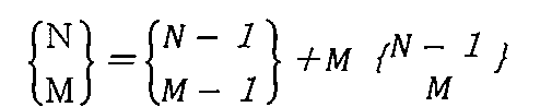


T(N,M)は、より直感的には、次のように表すこともできる。NをM個の整数の和として表すすべての方法(順序を区別するものとする)の集合をD(N,M)とおき、D(N,M)の元を


種々のN,Mに対するT(N,M)の値は次の表に示す通りとなる。空欄はM>NでありT(N,M)が定義されないことを意味する。与えられたNに対する時系列検知パターンの総数は、各行に書かれた数値の総和で与えられることになる。
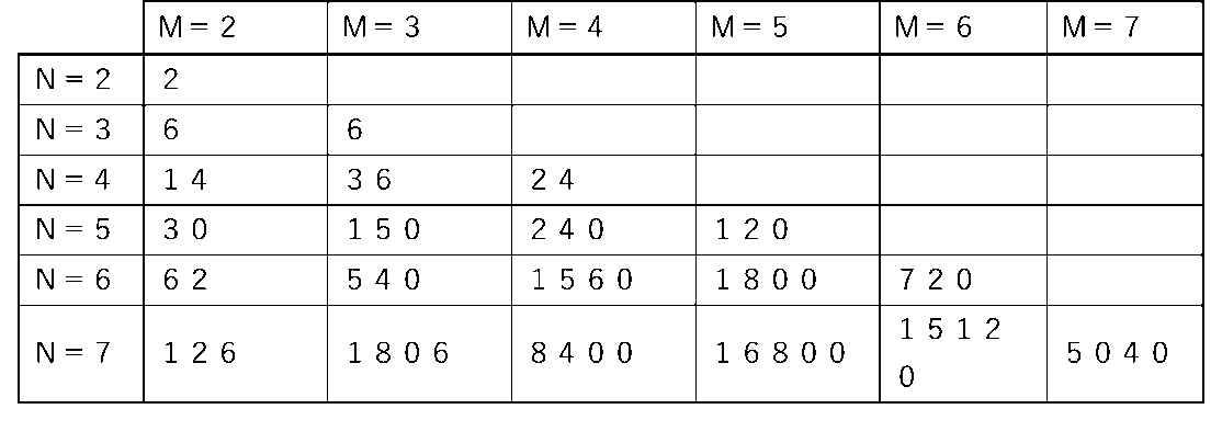
(通信処理部を備えるコード発生装置として適用可能なスタンプの形状)
図40~図44に他の形状のスタンプの例を示すが、これらについても、本実施形態の通信処理部32を搭載することが可能である。
図40~図44に他の形状のスタンプの例を示すが、これらについても、本実施形態の通信処理部32を搭載することが可能である。
図40は、底面部4に複数の電極5が平面性を保つように電極5の表面がむき出しで埋め込まれているような立体形状のスタンプであり、情報処理装置のタッチパネル31に接触または略接触することにより、指で保持した接触部の導電材21から導電材で接続された電極5が検知され電極パターンである電極コードが認識される。
図41は、底面部4に突起物の形状で電極5がむき出しで設けられているような立体形状のスタンプであり、情報処理装置のタッチパネル31に接触または略接触することにより、指で保持した接触部の導電材21から導電材で接続された電極5が検知され電極パターンである電極コードが認識される。
図42は、底面部4に非導電性材料の基材(板やシート)に柱状かつ上下方向に伸縮性を有する電極5が配置され、スタンプを押下させることによって、指で保持した接触部の導電材21から導電材で接続された導電性基材(板)の可動電極25と電極5が接触して導通するスタンプを示す。柱状の電極5の高さを異ならせることによって、押下時に電極5が上下方向に縮み、段階的に導通する電極5が増加し、その段階的にタッチパネル31によって検知される電極パターンの組み合わせを数値化して、多くの電極コードを定義できる。
図43は、スタンプを押下させることによって、指で保持した接触部の導電材21から導電材で接続された導電性基材(板)の可動電極25に、下向きに設けられた柱状かつ上下方向に伸縮性を有する電極5が底面部4の非導電性材料の基材(板やシート)に接触して、タッチパネル31によって当該電極5が検知されるスタンプを示す。柱状の電極5の高さを異ならせることによって、押下時に電極5が上下方向に縮み、段階的に導通する電極5が増加し、その段階的に検知される電極パターンの組み合わせを数値化して、多くの電極コードを定義できる。
図44は、壁やポスターに設けられ、裏面に導電材で接続された複数の電極5が形成された凸状の接面領域40を有する薄板状の媒体からなるスタンプである。凸状の接面領域40にスマートフォンを接触または略接触させることによって、スマートフォンが電極5を検知し、電極パターンにより電極コードが認識される。電極5を接続する導電材の端部には、接触部としての導電材21を設け、十分な面積を確保して指や人体もしくは、スマートフォンの筐体と導電材21の間に寄生的にACカップリングを起こし、電極5を接続する導電材とスマートフォンの筐体をACで導通させることにより、電極5を検知させる。また、この導電材21を線状に所定の長さで形成することによって、WiFi等の周囲環境にある波長と共振させ、AC振幅を補助し、スマートフォンの筐体との導通を助け電極5を検知し易くしてもよい。さらにまた、薄板の表面に接触部の導電材21を露出させ、指で触れて人体、スマートフォンの筐体と導通させてもよい。
[実施の形態9]
(電極パターンの読み取り)
コード発生装置120(スタンプやカード)の筐体表面に形成された導電材(直流導通)または、非導電材で被覆された導電材(交流導通)からなる接触部21に人体が接触または接触部21を保持すると、接触部21と導電材と接続された電極5に直流または交流で導通される。装置に接触または装置を保持したまま、装置を、タッチパネル31を有する第1の情報処理装置310(スマートフォン)のディスプレイに押し当てたりかざしたりすることにより、第1の情報処理装置310が、コード発生装置120の底面部に取り付けた電極5の幾何学的配置を読み取り、その幾何学的配置に基づく電極コードと対応させて、その配置を認識する。一般的なNFC(Near Field Communication)技術に基づく手法とは異なり、静電容量の変化を伴う技術であるため、両者間の接触または略接触を必要とする。スマートフォンの一般的な保護シートは、静電容量の検知を妨害しないため、貼ってあっても貼ってなくてもよい。静電容量に基づく電極5の幾何学的配置の検知を妨害しない限り、その他の修飾が施されてもよい。導電材ではないスイッチなどにより導通状態を制御したり、その他の物理量変化を静電容量の代わりに適用したりしてもよい。
静電容量による導電材との導通経路に組み込まれて検知されるすべての電極5のみを筐体底面部に配置するのが基本的な電極パターンの構成であるが、配置可能位置の他の箇所の一部またはすべてにも電極5を置き、導通経路の少なくとも一部を電気的に導通または遮断させて、他の電極配置パターンを形成させ、複数の電極パターンを利用できるようにしてもよい。その場合に、いずれの電極パターンにも使われない電極5があってもよい。また、単一の電極パターンのみを利用する場合も、使われない電極5があってもよい。第2の操作部6としてコード発生装置120に押圧機構、または、スイッチを備え、その操作部6の操作によって切り替えが物理的にもたらされてもよい。また、導通制御部79を設けて電子制御により切り替えができるようにしてもよい。電極5の配置領域としては、底面部のみならず、他の場所にあってもよい。すなわち、タッチパネル31と接触または略接触する面は、筐体2の表面の複数の領域にあってもよい。そのようにすると、タッチパネル31に接触または保持させる領域によって、導電材と接続される電極パターンを異なるようにし、複数の異なる電極コードを第1の情報処理装置310に認識させるようにしてもよい。その他の切り替え方法としては、切り替えスイッチを設けたり、多段階の押下による多段階接続の機構を設けたり、コード発生装置120の回転または移動、あるいは、それらの組み合わせで制御できる機構にしたり、導電材の持ち方や持ち位置を変えて制御できる機構にしたりしてもよい。
コード発生装置120が発生する電極パターンは、利便性のために、数値化することが望ましいが、その数値で、そのコード発生装置120に割り当てた電極コードであってもよいし、数値を分割して、一部を例えば、第1の情報処理装置310に対して、所定の情報処理を指示するコードに割り当て、残りをコード発生装置120に割り当てた識別コードにしてもよい。その実施例として、予め、配置された電極5の一部を、第1の情報処理装置310に対して、所定の情報処理を指示するコードに割り当て、残りの配置パターンを装置識別コードに割り当ててもよい。その情報処理は、例えば、ポイントの「付与」、「消込」、「決済」や「中止」等であってもよい。電極コードが切り替え可能な場合、複数の電極コードに対応する通信アドレスを共通にしておけば、第1の情報処理装置310と接続することができる。電極コードを切り替え可能な形態にすれば、さらに多くの情報処理の指示が可能であり、装置や情報処理装置の接続や切断も容易に可能となる。さらに、電極コードに対応する通信アドレスを認識している第3の情報処理装置330と第1の情報処理装置310とを接続させたり、電極コードに対応する通信アドレスを認識している第2の情報処理装置320とコード発生装置120とを接続させたりしてもよい。
(コード発生装置IDと通信アドレス)
電極パターンによって、割り当てることのできる電極コード数(ID数)は、コード発生装置120の電極パターンが構成および機構(図2の説明から実施の形態7の説明に至るまでの範囲で示されている例)によっても、数100から多くても数千までである。しかし、そのID数を超えない限り、コード発生装置120がスタンプの場合は、店舗につき、1つで十分な場合が多く、複数ID数が必要な店舗でも異なる電極コードを有するスタンプが数個あれば足りるため、ID数が少なくてもスタンプを識別する上で支障がない。しかし、ブルートゥース(BLEを含む)のおよぶ通信範囲で同じ電極コードを有するコード発生装置120が複数存在する場合がある。例えば、携帯しやすいカードの場合は個人に配布することになるが、数千では足りないので、同じ電極コードを割り当てせざるをえない場合が出てくる。そうすると、カードを用いるゲームやイベントなどや、カード保有者に所定のサービスを提供するために集客したユーザが、特定の場所に集まり、同じ電極コードのカードが複数その領域に存在する可能性が生じる。第1の情報処理装置310は、特定のコード発生装置120と接触した後に、通信先として接触されたコード発生装置120を認識しようとするが、同じ電極コード(通信アドレス)を割り当てられたコード発生装置120が、近傍に複数存在した場合に、第1の情報処理装置310のタッチパネル31に接触または略接触したコード発生装置120を特定できない可能性がある。その結果、誤認接続があった場合は、セキュリティに関わる重大な問題となる可能性がある。
電極パターンによって、割り当てることのできる電極コード数(ID数)は、コード発生装置120の電極パターンが構成および機構(図2の説明から実施の形態7の説明に至るまでの範囲で示されている例)によっても、数100から多くても数千までである。しかし、そのID数を超えない限り、コード発生装置120がスタンプの場合は、店舗につき、1つで十分な場合が多く、複数ID数が必要な店舗でも異なる電極コードを有するスタンプが数個あれば足りるため、ID数が少なくてもスタンプを識別する上で支障がない。しかし、ブルートゥース(BLEを含む)のおよぶ通信範囲で同じ電極コードを有するコード発生装置120が複数存在する場合がある。例えば、携帯しやすいカードの場合は個人に配布することになるが、数千では足りないので、同じ電極コードを割り当てせざるをえない場合が出てくる。そうすると、カードを用いるゲームやイベントなどや、カード保有者に所定のサービスを提供するために集客したユーザが、特定の場所に集まり、同じ電極コードのカードが複数その領域に存在する可能性が生じる。第1の情報処理装置310は、特定のコード発生装置120と接触した後に、通信先として接触されたコード発生装置120を認識しようとするが、同じ電極コード(通信アドレス)を割り当てられたコード発生装置120が、近傍に複数存在した場合に、第1の情報処理装置310のタッチパネル31に接触または略接触したコード発生装置120を特定できない可能性がある。その結果、誤認接続があった場合は、セキュリティに関わる重大な問題となる可能性がある。
そこで、電極コード以外に、コード発生装置120に一意(固有)のコード発生装置120ID(以下、装置ID)を設定し、コード発生装置120の不揮発メモリに格納して、装置IDを情報処理装置に送信すれば、当該コード発生装置120を識別できる。また、第1の情報処理装置310が、コード発生装置120の通信処理部32と接続状態となるためには、通信アドレスを認識する必要がある。なお、接続状態にする際には、自動的に接続されるようにしてもいいし、あるいは、一旦接続待ち状態となり、第1の操作部78としてコード発生装置120に押圧機構、または、スイッチを備え、その操作部78の操作によって接続状態となるようにしてもよい。電極コード、装置IDと通信アドレスの対応関係が重要なので、以下に、通信処理部32の記憶手段に格納される一意の装置ID、または、電極コードと組み合わせて一意となる装置IDと、電極コードおよび通信アドレスの対応関係を例示した表を示す。
図45の表では、具体的な数値を用いて電極コード、装置IDと通信アドレスの関係性を例示する。ここで示すように、すべてのコード発生装置120に異なる装置IDが割り当てられているので、装置IDのみですべてのコード発生装置120が識別できるが、電極コードと通信アドレスを対応させてもよい。つまり、装置IDがID1,051,000,001とID1,051,000,002とで異なっていても、同じ電極コード1051に対応させて同じC-Stamp1051の通信アドレスを割り当ててもよい。
そして、図46の表では、電極パターンの一部を機能、一部を電極コードに割り当てた場合を例示する。ここでは、電極パターンから認識される電極コードの上2ケタを機能用のコードに割り当て、下2ケタをコード発生装置120の識別コードに割り当て、さらに、図45の表と同様に、電極コードと通信アドレスを対応させて同じものとしている。例えば、電極パターン1051の上2ケタの10が何らかの機能に対応し、下2ケタの51がコード発生装置120の識別コードに対応する。そして、通信アドレスがこの下2ケタの51に対応したコードに対応している。
また、図47の表では、図45の場合と同様に、装置IDとして一意のものを割り当てているが、通信アドレスも装置IDに対応させて装置毎に異なる通信アドレスを割り当ててもよい。つまり、同じ電極コード1051の装置であっても、装置IDがID1,051,000,001とID1,051,000,002とで異なっている場合は、それぞれの装置にC-Stamp1,051,000,001とC-Stamp1,051,000,002と異なった通信アドレスを割り当ててもよい。
さらに、図48と図49の表では、図45の場合と同様に、装置IDとして一意のものを割り当てているが、通信アドレスとして、電極コードまたは装置IDのNに対して何らかの関数f(N)を適用させて生成させたコードを割り当ててもよい。その通信アドレスは、図48の場合のように、電極コードが一致する装置の場合は、同じ通信アドレスにしてもよい。あるいは、図49の場合のように、装置ID毎に異なる通信アドレスを割り当ててもよい。
コード発生装置120をそれぞれ識別できればいいので、電極コードと装置IDの組合せで、一意にしてもよい。つまり、電極コードが異なれば、同じ装置IDがあってもよい。例えば、図50に示されているように、電極コード1051と1052に対して、それぞれで装置IDとしてID1,000,000,001があってもよい。
ただし、図45~49の表のように、装置IDをすべて一意(固有)のものにした場合は、装置IDで電極コードを識別できるので、電極コード認識の際のエラーチェックができるという利便性がある。例えば、ID1,051,000,001~ID1,051,100,000の装置IDを有するコード発生装置120は、必ず1051の電極コードを有することになる。
図示しないが、それぞれのコード発生装置120の通信処理部32にビーコンを搭載した場合には、ビーコンに一意の通信用IDが割り当てられており、これを装置IDとしてビーコンからビーコンを認識できる情報処理装置に発信してもよい。その他、異なるコード発生装置120の識別が必要とされる状況において識別が確実にできれば、上記以外にどのような方法を用いてもよい。また、複数の方法を組み合わせてもよい。
また、電極パターンが切り替え可能なコード発生装置120では、簡単な切り替え機構である場合、切り替え毎に異なる電極パターンが検知されることになり、一つのコード発生装置120で、切り替えの回数の分(複数)の装置IDを有することになる。しかし、複数の電極コードを組にして読み取りの順番も規定したり、電極コードの読み取り方を工夫したり、することによって、装置IDを増やすことができる。ここでは、この2つのパターンの例について説明する。
図51の表に前者の例として、3つの独立した電極コードが切り替え可能な場合を示す。例えば、装置個体1が、切り替えによって、順に1051、1052、1053の3つの電極コードを第1の情報処理装置310に読み取らせることができるとすると、1051-1052-1053の装置IDを有するコード発生装置120と見なすことができるが、これを参考にすると、装置個体2の組からなるコード発生装置120では、1051-1052-1054の装置IDを有するコード発生装置120、装置個体3の切り替えからなるコード発生装置120では、1052-1051-1053の装置IDを有するコード発生装置120、装置個体4の切り替えからなるコード発生装置120では、1051-1051-1053の装置IDを有するコード発生装置120と割り当てることができる。このようにすると、電極コードの数に対してコード切り替えの回数を次数とした数の固有のIDをとることができ、識別できる装置の数が格段に増える。例えば、電極コードの数が1,000あり、切り替えが3回できるとすると、理論上、10憶(1,0003)の装置が識別できることになる。ただし、このような場合は、装置IDに含まれる電極コード(複数)をすべて認識しなければならないので、電極コードを順次切り替えながら第1の情報処理装置310に読み取らせる必要がある。通信アドレスは、114~119のように、共通であってもよいし、120のように独立していてもよい。
図52~図55を用いて、電極5に導通された場合は、正常に検知するが、導通を遮断した場合、非検知とならないスマートフォンを対象にする場合を想定し、時系列において、各段階で導通させる電極5を追加していく実施例について説明する。なお、電極5の個数は、一般的なマルチタッチパターンである5点の場合とする。なお、白丸は導通されていない(OFF)電極5、黒丸は導通されている(ON)電極5を示す。5点の電極5によるパターンは、一段階での検知であれば、所定個数の電極5の配置による電極配置パターンの生成だけであり、僅かな数の電極コードしか生成できない。ところが、段階的に検知される電極5を増やすことができれば、一つの電極配置パターンで多数に増やすことができる。
図52に示すように、5段階で増やす場合、STEP5の状態で最終的に形成される電極パターンは、復号化処理において電極番号E1からE5の配置位置が特定できるため、STEP毎に検知された順に従って電極5に仮の電極番号を付与し、検知された電極5の座標値をデータとして記憶しておくことで、STEP1からSTEP5までの電極5の導通シーケンスと電極配置パターンにより時系列電極コードを求めることができる。図52のように5個の電極5を5STEPで各1個ずつONさせていく場合、時系列電極パターン数は、5!=120通りとなる。
図53に示すように、4段階で増やす場合は、その内の1回で2つ増やすことになり、2つ増やす段階を4段階で設定できることから、5C2×3!×4=240通りとなる。図54に示すように、3段階の場合は、3つ増やす段階が1つと1つ増やす段階が2つの場合(図54(A))と、2つ増やす段階が2つと1つ増やす段階が1つの場合(図54(B))の2通りが可能で、それぞれ増やす段階の選び方として3通り可能である。従って、それぞれ、5C3×2!×3=60通り、5C2×3C2×1!×3=90通りとなる。さらに、図55に示すように、2段階の場合は、4つ増やす段階と1つ増やす段階がそれぞれ1つの場合(図55(A))と、3つ増やす段階と2つ増やす段階がそれぞれ1つの場合(図55(B))が可能で、それぞれ増やす順番として2通り可能である。従って、それぞれ、5C4×1!×2=10通り、5C3×2C2×2=20通りとなる。合わせると540通りである。なお、時系列電極パターンのため1段階の場合の1通りを含んでいない。このように、5個の電極5からなる電極配置パターンを形成する電極5を段階的に導通(ON)させることにより、電極コードの数を540倍に増やすことができる。なお、スマートフォンのパネルによる時系列電極パターンを確実に認識させるためには、各STEPの電極5をONさせている時間は、51msec以上必要であり、100msecあればなおよい。ここでの説明は、5個の電極5のパターンについてのものであるが、4つ以下の電極5でもよい。図示しないが、4つの電極5で電極配置パターンを形成させる場合は、同様に計算すると74通りである。すなわち、電極配置パターンに対して最大で74倍の電極コードを生成することができる。また、6点以上のマルチタッチが実現可能な場合は、その数に合わせて段階数を増やし、同様に装置ID数を増やしてもよい。
次に、電極端部間距離を7~8mm程度にして電極5の配置パターン数を増加させた場合、近接する電極5の端部間の距離が短いと、近接する2以上の電極5が融合されて1個として検知されないように、一旦導通した電極5を次の段階で遮断するのが望ましい。この場合、データ処理段階において仮想的に追加していけばよい。図56(A)で例示しているように、5段階(STEP1~5)のそれぞれで一つずつの電極5のみを検知し、STEP6では、×印で示すように、STEP5までで記憶された5個の異なる検知座標値を仮想的に追加して、電極配置パターンとすればよい。
このように各STEPで導通させる電極5を1個として順次切り替えていくようにしても、STEP毎に検知された順に従って電極5に仮の電極番号を付与し、検知された電極5の座標値をデータとして記憶しておくことで、図52と全く同様にSTEP1からSTEP5までの電極5の導通シーケンスと電極配置パターンにより時系列電極コードを求めることができ、時系列電極パターン数は、5!=120通りとなる。ここでは、5個の電極5を次々に導通させ、他の電極5の導通を遮断しているが、近接する電極5を同時に導通させないことを条件にすれば、2段階から4段階で時系列電極パターンを形成することにより、さらに大量の電極コードを生成できる。
さらに、常にONしている電極5に隣接する電極5は必ずOFF状態とすることにより、前述の隣接する2電極間の距離が近い場合に、タッチパネル31が1つの電極5として検知してしまう現象を抑制することができる。なぜなら、隣接する片方の電極5は導通されていないため2pF程度の物理量であり、一方、導通されている電極5は4pF以上を有することから、相対的に導通されている電極5の検知強度が支配的になり、当該電極5の座標位置を概ね正確に検知できるからである。このため、電極配置パターン作成時に隣接する電極端部間隔の制約を緩和でき、電極配置パターン数を大幅に増やすことが可能となる。
図56(B)に、(A)と同じ仕様であるが、各STEP間でONした電極5を次のSTEPでOFFにしたにも関わらず、タッチパネル31で前STEPの検知電極5が検知され続けてしまう場合の例を示す。ここでも、白丸はOFFの電極5、黒丸は導通されている電極5で、斜線パターン付きの丸は、制御では導通状態から導通を遮断しているにも関わらずタッチパネル31に検知されている電極5を示す。図のように、仮に、各STEPでタッチパネル31に電極5が1個よりも多く検知されても、各STEPで新たに記憶される電極位置は、(A)の場合と変わらないため、(A)と同一の電極ONシーケンスの時系列電極パターンとすることができる。
また、図56(B)のSTEP4の状態の様に、導通されている電極E5と制御上導通されていない状態でタッチパネル31に検知されている電極E4が近い場合が想定されるが、導通されていない電極5がタッチパネル31に検知される場合の検知強度は、導通されている電極5が検知される場合よりも十分に低いため、(A)と同様に、タッチパネル31が1つの電極5として検知してしまう現象を抑制することができる。その結果、STEP4において電極E4が非検知となる場合がある。このように、非検知となるスマートフォンを対象にすれば、非検知となった電極5を再度、導通させて電極ONシーケンスを増やし、時系列電極コードをさらに増加させることができる。なお、スマートフォンのパネルによる電極パターンの変化を確実に認識させるためには、電極5の導通を遮断させる場合も51msec以上必要であり、他のアプリが稼働してCPUに大きな負荷が掛かっている場合は、タッチイベントが遅れて出力されることがあり、100msecあればなおよい。なお、51msecの根拠は、ディスプレイの画像表示フレームレートの1/60秒に合わせてタッチイベントを出力するスマートフォンがあり、同じタッチ位置が2回続けて検出された後に、当該位置のタッチイベントが出力されるよう設定されている。その場合、図57のようにパネルの電極5が走査線により検出開始する位置(タッチパネル31のコーナー)にあり、かつ、当該電極5に導通された瞬間(t=t1)には、電極位置を過ぎた位置から走査線による検出が行われている場合、当該電極5を2回(t=t2およびt=t3)検出してタッチイベントを出力するには、最大で3フレーム表示後にタッチイベントが出力されることになる。そこで、3フレーム×1/60秒=50msecを超える間隔、若干の余裕を持って51msec以上の間隔を置いて、次の段階の電極5を導通させれば、スマートフォンが同一段階の1以上の電極5を検知するには、同一フレームか、続く2回のフレームでタッチイベントが出力されるかのどちらかである。その結果、タッチイベントが出力されない1以上のフレームを認識した場合は、その間が時系列電極コードを形成する電極パターンが変化する切り替え点であることを認識できる。なお、1回のタッチを認識したら、ディスプレイの画像表示フレームレートの1/60秒に合わせてタッチイベントを出力するスマートフォンもあり、さらに、上記フレームレートに関係なくタッチを認識したら直ちにタッチイベントを出力するスマートフォンもある。その場合は、さらに短い間隔で段階毎の電極パターンを形成してもよい。一度、検知された電極の座標値が記録されれば、次の電極検知段階で、導通を遮断された電極5が検知されたままの場合や新しく検知した電極5との距離が近い場合でも、新しく検知した電極5の座標値を当該検知段階で正しく認識することが可能なので、OFFにするためのインターバルを設ける必要はないが、OFFにするためにインターバルを設けるのであれば、検知に必要な51msecと同じ程度のOFF時間をおいてもよい。検知される電極5が融合しない距離にある場合は、所定の一段階で複数の電極5を読み取るようにしてもよく、その場合は、場合の数を増やすことができる。また、同じ電極パターンでも、時系列で電極5の読み取り順序を変えることができれば、一つの電極パターンで膨大な数の装置IDを形成させることができる。上記と同様に、5個以外の数の電極5による電極パターンに適用してもよい。以上のように、時系列電極パターンの形成により膨大な数の時系列電極コードを生成できれば、装置IDとして使用すればよく、装置IDを送信する目的のみに必要な情報通信であれば、通信処理部32を設けなくてもよい。なお、その場合、電極5の導通および遮断を切り替える導通制御部79と必要な電子部品を設けなければならないことは言うまでもない。
また、固定した装置IDを予め通信処理装置の記憶手段に記憶させてもよいが、装置IDを可変にし、時間情報と組み合わせて装置IDを所定時間毎に変化させてもよい。このような場合には、ワンタイムパスワードのように、所定時間または所定回数でしか使用できないようにして、セキュリティを高めることができる。セキュリティの保持に有効であれば、その他の変化方法を利用してもよい。また、変化方法を組み合わせて利用してもよい。
以上示した方法を組み合わせてもよい。また、全てのコード発生装置120を識別できれば、その他どのような装置IDのつけ方でもよい。
装置IDの大きさとしては、金融業界において一般的である256bitでもよい。なお、第1の情報処理装置310で稼働するアプリに、対象となる装置IDを予め登録しておいて照合や認証してもよいし、サーバ等(クラウドを含む)の第3の情報処理装置330に登録された装置IDで照合や認証してもよい。第1の情報処理装置310によるローカルでの認証は、ネットに接続できない地域や災害時、イベント等で大勢の人が密集して接続しづらい状況においても、コード発生装置120の使用が可能となる。しかし、装置IDの登録に関しては、コード発生装置120が増えた場合を見越しての登録をしてもよい。また、コード発生装置120が盗まれたり、紛失したり、偽造されたりした場合は、ネットと接続できる状態にある時には、それらの情報を第3の情報処理装置330から取得して、第1の情報処理装置310の登録情報を更新する必要がある。
(第1の情報処理装置310のタッチパネル31に接触したコード発生装置の認識)
既に説明したように、コード発生装置120を第1の情報処理装置310のタッチパネル31に接触または略接触させると、その電極パターンを第1の情報処理装置310が読み取り、その電極パターンに基づく電極コードを認識する。コード発生装置120と接続するには、第1の情報処理装置310がその電極コードに対応するコード発生装置120と接続する必要があるので、その電極コードまたはその一部に対応する通信アドレスを検索する。該当する通信アドレスが一つのみの場合は、それに対応するコード発生装置120と接続状態を確立すればよいが、検索の際に、電極パターンが同じであるコード発生装置120が複数近傍に存在する可能性、すなわちコード発生装置120の通信処理部32の通信アドレスが同じであるコード発生装置120が複数近傍に存在する可能性がある。そのような状況に備えて、タッチパネル31に接触または略接触する状態を感知する感知部をコード発生装置120が備える例を含む以下のような方法を用いて、タッチパネル31が検知した電極コードの少なくとも一部に対応する通信アドレスと組み合わせて、タッチパネル31と接触または略接触したコード発生装置120の通信処理部32のみを選択的に認識して接続状態を確立してもよい。その感知部は、物理量の変化を検出する構成単位であってもよい。
(1)第1の情報処理装置310が検索した同一の通信アドレスを有する複数のコード発生装置120に順次接続して、コード発生装置120の押下時の時間情報と、第1の情報処理装置310にコード発生装置120が接触された時間情報をそれぞれで認識し、コード発生装置120が押下した時間情報を第1の情報処理装置310に送信し、第1の情報処理装置310が受信したその押下時間と第1の情報処理装置310に記憶されたコード発生装置120が接触または略接触した時間が概ね同一であれば、接触または略接触したコード発生装置120であることが特定できる。その結果、コード発生装置120から取得した一意の装置IDにより、押下したコード発生装置120を認識できる。
(2)第1の情報処理装置310のタッチパネル31にコード発生装置120が接触または略接触した際に、タッチパネル側の表面に発生する物理量が変化するが、感知部として当該物理量を検出するタッチパネル認識センサ134をコード発生装置120の所定の位置に搭載させ、検出された物理量の変化がコード発生装置120をタッチパネル31に接触または略接触させたことによるものかどうかを解析すればよい。接触または略接触の可否が認識できれば、コード発生装置120の通信処理部32を接続待状態にして、第1の情報処理装置310が当該通信処理部32の通信アドレスを検索して接続し、装置IDを取得すればよい。上記の物理量は、例えば、抵抗方式タッチパネル31の抵抗値であってもよい。
(3)コード発生装置120から距離が最も近い第1の情報処理装置310を認識する方法として、ビーコンを利用する。コード発生装置120にビーコンを内蔵して、第1の情報処理装置310に搭載されたブルートゥース(BLEを含む)の電波強度検出機能を利用してビーコンにより発信された電波を検知すれば、距離に応じた接続が可能となる。特に、第1の情報処理装置310がコード発生装置120に対して1m以内のごく近距離にあることになるので、電波強度検出装置によりビーコンの電波強度から最も近い第1の情報処理装置310を認識して接続し、装置IDを送信すればよい。また、GPSを使用して位置を互いに認識してもよい。例えば、コード発生装置120にGPSを設け、第1の情報処理装置310に備えられたGPSとで互いの位置を認識して、2者の間の最も短い距離からコード発生装置120を特定すればよい。すなわち、(1)のように、第1の情報処理装置310が検索した同一の通信アドレスを有する複数のコード発生装置120に順次接続して、コード発生装置120から位置情報を受信し、第1の情報処理装置310から所定距離の範囲であって、最も近いコード発生装置120を認識して接続し、装置IDを取得すればよい。
(4)コード発生装置120のタッチパネル接触面側に感知部として光検知センサ、すなわち、光受光部360(フォトダイオード)を設け、タッチパネル31に接触または略接触して第1の情報処理装置310が電極パターンを検知したら、その電極パターンからそれらの光センサの位置が認識され、タッチパネル31から少なくとも接触を知らせる光コードを発光させるようにし、コード発生装置120がその光コードにより接触または略接触の可否が認識できれば、コード発生装置120の通信処理部32を接続待状態にして、第1の情報処理装置310が当該通信処理部32の通信アドレスを検索して接続し、装置IDを取得すればよい。光コードとは、光の色、強さ、光点滅の時間変化や、それらのいずれかの組み合わせで形成された光パターンを数値化したコードのことである。時間変化としては、それぞれの時間間隔を変えてモールス信号のようにしてもよい。すなわち、光の色および、光の強さ、点滅時間の少なくともいずれかを時系列で変化させることによって、その履歴により形成される時系列データを光コードとしてもよい。また、複数の光受光部360を設けた場合は、タッチパネル31は、検知した電極5のユニークな形状や電極パターンのユニークな幾何学的配置から、当該複数の光受光部360の位置を認識して、各光受光部360毎に発光すればよい。当然、発光を時間変化させて時系列データとしてもよい。なお、光受光部360が1個のみ設けている場合も同様に、検知した電極5から当該位置を認識して光コードを発光してもよいし、タッチパネル31に予め定められた少なくともコード発生装置120の接触領域全体で光コードを発光してもよい。
この光コードは、接触または略接触の可否の情報を受信するだけではなく、第1の情報処理装置310から送信される様々な情報を含めることができる。例えば、個人情報や決済情報、ポイントやクーポン情報、プリペイドの残高情報、交通および宿泊やイベント等の様々なチケットの購入情報、様々な会員情報、ID、パスワード等の様々な情報が含まれてもよい。これにより、第1の情報処理装置310とコード発生装置120との接続状態を確立しなくても情報の送受信が可能となる。さらに、前述した電気的電極パターン切り替え可能なコード発生装置120を用い、通信処理部32で稼働するプログラムにより、受信した情報に対応する情報を電極コードとして、電極パターン切り替えにより送信してもよい。その際、通信処理部32の無線接続機能を搭載しなくてもよいし、第2の情報処理装置320との接続による情報の送受信のため、残しておいてもよい。上記は、本明細書に記載されたコード発生装置120の構成とどのように組み合わせてもよい。
接続方法は上記のいずれか、またはそれらの組み合わせに限られず、第1の情報処理装置310のタッチパネル31に接触したコード発生装置120を認識して両者が接続することができれば、どのような方法であってもよい。
以下に、接続状態となるための情報の送受信、接続状態となってからの情報の送受信および情報の送受信に基づく情報処理について説明する。
(コード発生装置と第1の情報処理装置との接続)
本発明では、前述した通り、コード発生装置120と第1の情報処理装置310の通信接続により、他の情報処理装置との接続を含めた情報処理を行ってもよい。その接続の過程を図58に段階ごとに例示する。
本発明では、前述した通り、コード発生装置120と第1の情報処理装置310の通信接続により、他の情報処理装置との接続を含めた情報処理を行ってもよい。その接続の過程を図58に段階ごとに例示する。
まず初めに、コード発生装置120を第1の情報処理装置310に接触させる。立体形状のスタンプの場合は、コード切り替えスイッチ131を操作したり、電源のON/OFFスイッチを操作したり、取っ手の接触部21(人体接触導電材21と同義)の部位を握ったまま第1の情報処理装置310に、スタンプ型の場合は載置させ、カード型の場合は電極配置領域を接面したりして接触または略接触するようにすればよい。板形状のカードの場合も、電源のON/OFFスイッチを操作したり、導電材で形成された接触部21の部位を保持して第1の情報処理装置310に接触または略接触するようにすればよい(S11)。第1の情報処理装置310は、コード発生装置120の電極パターンを検知するようにすればよい(S12)。そこで、第1の情報処理装置310が電極パターンに対応する電極コードを認識するようにすればよい。(S13)。そして、第1の情報処理装置310は、予め記憶された電極コードに対応する通信アドレスを検索する(S14)。なお、電極コードの少なくとも一部から所定の規則に基づいた通信アドレスを認識できるようにすれば、第1の情報処理装置310に予め通信アドレスを記憶しておかなくてもよい。該当する通信アドレスが一つのみ検索された場合は、第1の情報処理装置310が、その通信アドレスに対応するコード発生装置120と接続するようにすればよい(S17)。接続されたコード発生装置120が、第1の情報処理装置310に固有の装置IDを送信する(S15)。装置IDを受信した第1の情報処理装置310は、装置IDからコード発生装置120を特定し、その装置を認識する(S16)。該当する通信アドレスに対応するコード発生装置120が複数あった場合(通信アドレスが同じ場合と異なる場合の両方がありうる)は、図示しないが、前述(第1の情報処理装置310のタッチパネル31に接触したコード発生装置120の認識)の(1)~(4)の少なくともいずれかの方法でコード発生装置120を特定し、第1の情報処理装置310は、そのコード発生装置120とのみ接続するようにすればよい(S17)。第1の情報処理装置310に接触または略接触したコード発生装置120を特定できるのであれば、他の手段に頼ってもよい。以上の手順で接続が認証されたら、引き続きコード発生装置120と第1の情報処理装置310との接続がなされ様々な情報を送受信すればよい。さらに、それを基に各種処理が行われてもよい。その処理とは、以下で示す各種情報処理装置との接続、所定情報の送受信、情報に基づく処理や通信の切断を含んでもよい。(S18a)。
上記とは異なる順番の手順でもよい。すなわち、コード発生装置120であることを認識できる固有の名称を通信アドレスに含んでいれば、第1の情報処理装置310が近傍にある複数のコード発生装置120と通信状態にし、第1の情報処理装置310によるコード発生装置120の電極コードの読み取りが行われてもよい。通信状態にある通信アドレスの中で検索した電極コードと対応するものが単一だった場合、直ちに接続状態となればよい。そうすると、接続時間が短縮され、電極コードが認識された瞬間に所定の処理が実施されうる。認識した電極コードに対応する通信アドレスが複数あった場合は、上記と同様に、前述(第1の情報処理装置のタッチパネル31に接触したコード発生装置の認識)の(1)~(4)の少なくともいずれかの方法でコード発生装置120を特定し、第1の情報処理装置310は、そのコード発生装置120とのみ接続するようにすればよい。第1の情報処理装置310と接触または略接触したコード発生装置120が特定できるのであれば、他の手段に頼ってもよい。逆に、検知した電極コードに対応する通信状態にある通信アドレスがなかった場合は、第1の情報処理装置310が、誤認があったことを通信状態にあるコード発生装置120に通知し、コード発生装置120からアラームを発生させ、再度コード発生装置120を第1の情報処理装置310に接触させることを促してもよい。第1の情報処理装置310にコード発生装置120を接触させて再び電極コードを読みとっても不一致であれば、通信を切断してもよい。なお、これらの処理を所定の回数実施してもよい。
(所定情報の真贋判定)
コード発生装置120と各種情報処理装置との間で情報の送受信をするに際して、情報が改ざんされたり、通信エラーにより情報の欠落が発生する可能性がある。そこで、送信側が元々の情報とそれを暗号化した情報を同時に送り、それらを受け取った受信側が暗号化情報を復号化し、元々の情報と比較して一致すれば、データが改ざんされていないことを確認することができる。図59にコード発生装置120から第1の情報処理装置310に送信する情報およびその暗号化情報を生成する過程を段階ごとに例示する。
コード発生装置120と各種情報処理装置との間で情報の送受信をするに際して、情報が改ざんされたり、通信エラーにより情報の欠落が発生する可能性がある。そこで、送信側が元々の情報とそれを暗号化した情報を同時に送り、それらを受け取った受信側が暗号化情報を復号化し、元々の情報と比較して一致すれば、データが改ざんされていないことを確認することができる。図59にコード発生装置120から第1の情報処理装置310に送信する情報およびその暗号化情報を生成する過程を段階ごとに例示する。
コード発生装置120と第1の情報処理装置310とが通信接続されている状況で、まず初めに、第1の所定情報を符号化手段で符号化情報に変換する。ここで、符号化とは、ハッシュ関数を用いてデータから不可逆的変換をして符号列を求めることを含む。そして、ハッシュ関数を用いて符号化された符号化情報はハッシュ値を含んでいる(T11)。次に、第1の所定情報の符号化情報を、暗号化手段を用いて暗号化情報に変換する(T12)。その第1の所定情報および第1の所定情報の暗号化情報をコード発生装置120の記憶手段に格納する(T13)。つづいて、図58の手順などを用いてコード発生装置120と第1の情報処理装置310を接続させる(T14)。そして、コード発生装置120が第1の情報処理装置310に第1の所定情報および第1の所定情報の暗号化情報を送信する(T15)。
図60に第1の情報処理装置310が受信する第1の所定情報およびその暗号化情報を読み取り、真贋判定(正誤判定)を行う過程を段階ごとに例示する。
第1の情報処理装置310が、接続されたコード発生装置120から送信されてきた第1の所定情報および第1の所定情報の暗号化情報を受信する(T21)。その第1の所定情報を符号化手段で符号化情報に変換する(T22)。さらに、第1の所定情報の暗号化情報を復号化手段で復号化情報に変換する(T23)。そして、符号化情報と復号化情報を照合する。例えば、符号化手段としてハッシュ関数を用いてハッシュ値に変換した場合は、ハッシュ値を照合する(T24)。符号化情報と復号化情報が一致した場合は、第1の情報処理装置310がコード発生装置120に対して認証の通知を第2の所定情報として送信する(T25)。符号化情報と復号化情報が一致しなかった場合は、第1の情報処理装置310がコード発生装置120に対して非認証の通知を第2の所定情報として送信する。第1の情報処理装置310による読み取り誤認のために情報が不一致になった可能性もあるので、通知には、再度の読み取りを促す内容が含まれてもよい。通知を受けたコード発生装置120は、アラームとして、その通知内容をディスプレイ付きの装置でテキストやグラフィックスとして、バイブレーター付きの装置で振動として、あるいは、音声出力装置など音声として使用者に知らせる。そのアラームが非認証を知らせるものの場合、使用者は、誤認があったと考えて、所定情報の再送を試みてもいいし、自ら切断させてもよい。再送の方法としては、再送スイッチを設け、そのスイッチ操作をして、既に読み込まれた情報を再送してもよいし、自動で再送される設定にしてもよい。あるいは、読み取り誤認があったと考えて、情報を読み直させるために、コード発生装置120を第1の情報処理装置310に接触あるいは略接触させ直してもよい(T26)。再送を試みた場合、読み取り誤認が多数回続くとは考えにくいので、所定の回数読み取りを試行しても不一致が続くようであれば接続を切断させてもよい。データの不備の場合もありうるが、その場合も試行を繰り返しても意味がない(T29)。情報の認証がなされたら、所定の情報処理が実施される(T27)。その処理の終了および処理の結果を第1の情報処理装置310が第2の所定情報としてコード発生装置120に送信してもよい(T28)。処理の終了の情報をもとに自動的に接続を切断する設定にしてもよい。あるいは、対話形式で接続を切断するかどうかを決めるようにしてもよい(T29)。その他、どのような条件で接続を切断してもよい。
この一連の手順はあくまでも例であり、同様に情報の信憑性を評価できるのであれば、どのような方法でもよい。また、上記の例では、第1の所定情報について示したが、第2~第8の所定情報の場合も同様の手順で送受信を行い、真贋判定を行って、その結果を所定情報の送信元に送信するようにしてもよい。
上記方法における暗号化手段としては、セキュリティレベルの高いものであればどのようなものでも構わないが、公開鍵―秘密鍵の組合せを用いることにより、高い機密性を保たせたり、高いレベルで完全性および真正性を保証したりすることが可能である。
情報の機密性を保持する方法を図61のフローチャートで例示する。所定情報の受信者が、公開鍵と秘密鍵をペアで用意をする(T31)。その内の公開鍵を所定情報の送信者に送信し、秘密鍵を厳重に保管する(T32a)。所定情報の送信者は、その公開鍵を用いて、所定情報を暗号化情報に変換する(T33a)。そして、所定情報の送信者が、その暗号化情報を情報の受信者に送信する(T34)。所定情報の暗号化情報の受信者が秘密鍵を用いてその復号化情報の変換を試みる(T35a)。その結果、復号化できない場合は、誤認、または、偽情報と判断し、受信者が送信者に措定情報の暗号化情報の再送信を依頼すればよい(T36)。復号化できる場合は、正しい情報と判断する。ペアの秘密鍵がなければ、基本的には、暗号化情報を解読することができないので、情報の送受信において、機密性を保持することができる(T37a)。所定情報の受信者が送信した公開鍵が盗まれて、それによって作成された偽の暗号化情報が送信されてきたとしても、送信先に問い合わせるか、予めIDについて決めごとをすれば、真偽を確認することができる。
一方で、電子署名付き所定情報の送受信に関しては、図62のフローチャートで例示する。所定情報の送信者が、公開鍵と秘密鍵をペアで用意をする(T31)。その内の公開鍵を所定情報の受信者に送信する(T32b)。所定情報の送信者は、秘密鍵を用いて、所定情報および署名情報を暗号化情報に変換する(T33b)。そして、所定情報の送信者が、その暗号化情報を情報の受信者に送信する(T34)。所定情報の暗号化情報の受信者が公開鍵を用いてその復号化情報の変換する(T35b)。その結果、復号化できない場合は、誤認、または、偽情報と判断し、受信者が送信者に措定情報の暗号化情報の再送信を依頼すればよい(T36)。復号化できる場合は、送信者の署名情報付きの情報であれば、正しい情報と判断できる。秘密鍵で作成された暗号化情報でなければ、ペアとなっている公開鍵で暗号化情報を復号化することができないので、所定情報に署名情報があれば、秘密鍵の所有者によって作成された暗号化情報であると判断できる(T37b)。所定情報の受信者が送信した公開鍵が盗まれた場合は、情報が漏洩する可能性があるが、書き換えができないので、情報の真正性および完全性を担保することができる。
なお、公開鍵―秘密鍵を利用する方法とハッシュ関数を利用する方法を組み合わせてもよい。
[実施の形態10]
第1~第3の情報処理装置の少なくともいずれかを含み、同一種の装置が複数ある場合を含めて装置が2つ以上ある情報通信システムでは、少なくともいずれかの装置の組合せが、一般的に、通信接続状態にある。例えば、職場等でスマートフォンとローカルサーバが常時WiFiで繋がっていたりする。本発明の情報通信システムでも、同様の接続状態が想定されるのは言うまでもないが、ここでは、その一般的な通信接続についての説明を省略し、コード発生装置120と第1の情報処理装置310との接続が契機(トリガー)となってコード発生装置120と第1~第3の情報処理装置の少なくともいずれかと接続状態が確立する情報処理システムにおける所定情報の送受信について、図63~図75で例示する。なお、図64~図75では、コード発生装置120と第1の情報処理装置310との接続状態の確立をもって、第1~第3の情報処理装置の少なくともいずれか2つの間の接続が確立されるようにしてもよい。
第1~第3の情報処理装置の少なくともいずれかを含み、同一種の装置が複数ある場合を含めて装置が2つ以上ある情報通信システムでは、少なくともいずれかの装置の組合せが、一般的に、通信接続状態にある。例えば、職場等でスマートフォンとローカルサーバが常時WiFiで繋がっていたりする。本発明の情報通信システムでも、同様の接続状態が想定されるのは言うまでもないが、ここでは、その一般的な通信接続についての説明を省略し、コード発生装置120と第1の情報処理装置310との接続が契機(トリガー)となってコード発生装置120と第1~第3の情報処理装置の少なくともいずれかと接続状態が確立する情報処理システムにおける所定情報の送受信について、図63~図75で例示する。なお、図64~図75では、コード発生装置120と第1の情報処理装置310との接続状態の確立をもって、第1~第3の情報処理装置の少なくともいずれか2つの間の接続が確立されるようにしてもよい。
(情報通信システム構成1:コード発生装置と第1情報処理装置)
図63は、最も基本となるコード発生装置120と第1の情報処理装置310からなるシステムの例を示す。コード発生装置120が第1の情報処理装置310と接続状態になった後、コード発生装置120と第1の情報処理装置310との間で第1および第2の所定情報のいずれかを送受信するシステムである。
図63は、最も基本となるコード発生装置120と第1の情報処理装置310からなるシステムの例を示す。コード発生装置120が第1の情報処理装置310と接続状態になった後、コード発生装置120と第1の情報処理装置310との間で第1および第2の所定情報のいずれかを送受信するシステムである。
この過程を簡略化したフローチャートとして例示したのが、図64である。まず、図58の手順などに従って、第1の情報処理装置310がコード発生装置120と接続状態になる(S21)。つづいて、コード発生装置120と第1の情報処理装置310の間で第1および/また第2の所定情報の少なくともいずれかを送受信する(S22)。例えば、第1の所定情報はコード発生装置120の装置IDでもよいし、予め記憶しておいた情報でもよい。この情報には、クーポンやポイントから、チケットやサービス、広告等の情報を送信してもよい。その後の第1の情報処理装置310から受信する第2の所定情報には、第1の情報処理装置310のIDやその所有者を特定する情報、第1の情報に対応する情報を含めてどのような情報でもよく、第2の所定情報をコード発生装置120の記憶手段に記録してもよい。その後、図65のシステムのように記録された情報は、第2の情報処理装置320に送信してもよい。なお、上記の送受信の順番が逆になってもよい。これら第1および第2の所定情報の少なくともいずれかに基づく処理が行われるが、コード発生装置120と第1の情報処理装置310の間の接続の切断が含まれてもよい。切断は、ユーザの操作や所定の情報の受信によって行う場合や最後のアクションから所定時間後に自動的に切断がなされる場合を含めてもよい(S18b)。
上記は基本的な手順であり、情報の送受信および情報処理は複数回あってもよい。
なお、第1の所定情報および以下に示す所定情報には、コード発生装置120の装置IDや電極コードの情報が含まれてもよい。さらに、所定情報には、時間情報または時間によって変化する情報を含めてもよい。また、第1の情報処理装置310や以下の第2の情報処理装置320と第3の情報処理装置330を特定するためのコード(第1の特定コード)として通信処理部32に割り当てられたMACアドレス、BDアドレス、SSID、ICCIDやIPアドレスなどの通信アドレスを用いてもいいし、稼働するソフトウェアやWEBサイトなどがそれらの情報処理装置に対して独自に設定するID(第2の特定コード)を用いてもいいが、第2の所定情報には、コード発生装置120の装置IDに加えて、情報処理装置の第1の特定コードと第2の特定コードの少なくともいずれかが含まれてもよい。所定の処理には、その他の各種情報処理装置との接続、所定情報の送受信、情報に基づく他の処理や通信の切断を含んでもよい。ここで示す所定情報やIDについては、例示しない構成も含めて、他の情報通信システム構成に適用してもよい。
スタンプラリーでは、コード発生装置120がデジタルスタンプの「付与」や「消込」などを第1の所定情報としてスマートフォンなどの第1の情報処理装置310に送信し、第2の所定情報としてスマートフォンから会員情報などの特定ID情報をコード発生装置120が受け取って、履歴を残すようにしてもよい。
(情報通信システム構成2:コード発生装置と第1と第2の情報処理装置)
図65は、コード発生装置120と第1の情報処理装置310と第2の情報処理装置320からなるシステムの例である。図63の構成にコード発生装置120が接続状態となっている第2の情報処理装置320を加え、コード発生装置120と第2の情報処理装置320とが第3および/または第4の所定情報を送受信するシステムを示す。
図65は、コード発生装置120と第1の情報処理装置310と第2の情報処理装置320からなるシステムの例である。図63の構成にコード発生装置120が接続状態となっている第2の情報処理装置320を加え、コード発生装置120と第2の情報処理装置320とが第3および/または第4の所定情報を送受信するシステムを示す。
この過程を簡略化したフローチャートとして例示したのが、図66である。第2の情報処理装置320とコード発生装置120が所定の方法で通信接続されており(S21a)、第2の情報処理装置320からコード発生装置120に第4の所定情報が送信され(S24)、その少なくとも一部がコード発生装置120の記憶手段に一時記録される。続いて、図58の手順などに従って、第1の情報処理装置310がコード発生装置120と通信接続し(S21)、記憶手段に記録された第4の所定情報の少なくとも一部を含み。コード発生装置120から第1の情報処理装置310に第1の所定情報が送信される(S22a)。その後、第1の情報処理装置310から第1の所定情報に基づく処理が行われ(S18ba)、その処理に対応した第2の所定情報をコード発生装置120に送信する。この際、の第1の所定情報に基づく処理には、コード発生装置120と第1および/または第2の情報処理装置320の間の接続の切断が含まれてもよい(S22b)。さらに、第2の所定情報の少なくとも一部を含むか、および/または第2の所定情報に対応する第3の所定情報を第2の情報処理装置320に送信する(S18bb)。
変法として、図67のフロ-チャートにも例示するように、次のような手順もある。まず、コード発生装置120と第2の情報処理装置320とが接続状態で、図58の手順などに従って、第1の情報処理装置310がコード発生装置120と接続状態になる(S21)。つづいて、コード発生装置120と第1の情報処理装置310の間で第1および/また第2の所定情報を送受信する(S22)。これら第1および第2の所定情報の少なくともいずれかに基づく処理が行われる。この処理には、コード発生装置120と第1の情報処理装置310および第2の情報処理装置320との接続および/または切断が含まれてもよい。なお、これらの処理は、他の情報通信システム構成に適用してもよい。さらに、コード発生装置120と第2の情報処理装置320が接続した状態で、第1の情報処理装置310がコード発生装置120に対して接続を求めてきた場合、コード発生装置120が第2の情報処理装置320との接続を切断して、第1の情報処理装置310と接続するようにしてもよい(S18b)。引き続き、コード発生装置120と第2の情報処理装置320が接続した状態で、第2の所定情報に基づいてコード発生装置120が第2の情報処理装置320に第3の所定情報を送信する(S23)。そして、上記少なくともいずれかの所定情報に基づく処理が行われる(S18c)。それから、第2の情報処理装置320がコード発生装置120に第4の所定情報を送信する(S24)。そして、上記少なくともいずれかの所定情報に基づく処理が行われる。なお、この処理には、コード発生装置120と第2の情報処理装置320の間の接続の切断が含まれてもよい。なお、図58に示す接続方法に伴う第1の情報処理装置310とコード発生装置120との接続状態に関わらず、コード発生装置120と第2の情報処理装置320が常に接続状態であってもよい。切断は、ユーザの操作によって行う場合や最後のアクションから所定時間後に自動的に切断がなされる場合を含めてもよい(S18d)。
最初の実施例はあくまでも基本的な手順であり、変法のように、手順の順番が変わってもよい。そして、情報の送受信および情報処理は少なくともいずれかが複数回あってもよいし、所定情報の送受信および情報処理の過程の少なくともいずれかが省略されてもよい。第1または第3の所定情報の少なくともいずれかには、コード発生装置120の装置IDや電極コードの情報が含まれてもよい。その他の所定情報にも含まれてもよい。さらに、所定情報には、時間情報または時間によって変化する情報を含めてもよい。また、所定情報の少なくともいずれかには、少なくともいずれかの情報処理装置の、第1の特定コードと第2の特定コードの少なくともいずれかが含まれてもよい。第1の所定情報は、第4の所定情報の少なくとも一部を含み、第3の所定情報は、第2の所定情報の少なくとも一部を含んでもよい。上記を含め、所定の処理には、第3の情報処理装置330と第1の情報処理装置310、または第2の情報処理装置320との接続、あるいは、コード発生装置120と第1の情報処理装置310、または第2の情報処理装置320との接続の少なくともいずれかの切断が含まれてもよい。所定の処理には、その他の各種情報処理装置との接続、所定情報の送受信、情報に基づく他の処理や通信の切断を含んでもよい。
スタンプラリーでコード発生装置120がデジタルスタンプをスマートフォンなどの第1の情報処理装置310に付与し、付与履歴を管理するような場合などでは、コード発生装置120が、第3の所定情報として、データ管理用の第2の情報処理装置320に、会員IDと関連付けて付与履歴を送るようにして、管理できるようにすればよい。
販売店における、ポイントやクーポンの「付与」および「消込」などの管理も、類似のシステム構成となる。
逆に、ユーザがカード型のコード発生装置120をクレジットカードおよびプリペイドカード等の金融決済カードやポイントカードとして用い、店舗の第1の情報処理装置310のタッチパネルにカードを接面させて、「決済」や、ポイントやクーポンの「付与」、「消込」等の処理を実施する場合に、第2の情報処理装置320が、ユーザのスマートフォンであれば、コード発生装置120の操作により第1の情報処理装置310で処理された決済明細や付与されたクーポンやポイントの残高が送信され、スマートフォンのディスプレイ上で確認することができる。なお、コード発生装置120の接続先が第1の情報処理装置310と第2の情報処理装置320の間で切り替わる場合は、接続の切断をしてから接続をすることになる。その際に、接続情報を保存したまま切断してもよい。なお、図58に示す接続方法に伴う第1の情報処理装置310とコード発生装置120との接続状態に関わらず、所定の操作に基づきコード発生装置120と第2の情報処理装置320が常に接続状態であってもよい。さらに、他の情報通信システムの構成でも同様である。同様に、情報処理装置とのホスト・ゲスト関係を逆にする際にも、接続情報を保存したまま一旦接続を切断してから、所定の方法(プログラムなど)に従って、第1の情報処理装置310がゲスト、コード発生装置120がホストとなるように情報処理がなされてもよい。
(情報通信システム構成3:コード発生装置と第1と第3の情報処理装置)
図68は、コード発生装置120と第1の情報処理装置310と第3の情報処理装置330からなるシステムの例である。図63の構成に第1の情報処理装置と接続状態となっている第3の情報処理装置330を加え、第1の情報処理装置310と第3の情報処理装置330とが第4および/または第5の所定情報を送受信するシステムを示す。
図68は、コード発生装置120と第1の情報処理装置310と第3の情報処理装置330からなるシステムの例である。図63の構成に第1の情報処理装置と接続状態となっている第3の情報処理装置330を加え、第1の情報処理装置310と第3の情報処理装置330とが第4および/または第5の所定情報を送受信するシステムを示す。
この過程を簡略化したフローチャートとして例示したのが、図69である。まず、図58の手順などに従って、第1の情報処理装置310がコード発生装置120と接続状態になる(S21)。つづいて、コード発生装置120と第1の情報処理装置310の間で第1および/または第2の所定情報を送受信する(S22)。これら第1および第2の所定情報の少なくともいずれかに基づく処理が行われる。この処理には、コード発生装置120と第1の情報処理装置310の間の接続の切断をしなくてもよい(S18e)。つぎに、第1の所定情報に基づいて第1の情報処理装置310が第3の情報処理装置330に第5の所定情報を送信する。なお、第3の情報処理装置330として、第2の情報処理装置320が使われてもよい(S25)。そして、電極コード(装置IDを含む)の認証を含む所定情報に基づく処理が行われる(S18f)。それから、認証結果に基づいて第3の情報処理装置330が第1の情報処理装置310に第6の所定情報を送信する(S26)。そして、上記少なくともいずれかの所定情報に基づく処理が行われる(S18g)。さらに、第6の所定情報に基づいて第1の情報処理装置310がコード発生装置120に第2の所定情報を送信する(S27)。そして、上記少なくともいずれかの所定情報に基づく処理が行われる。なお、この処理には、コード発生装置120と第1の情報処理装置310の間の接続の切断が含まれてもよい。切断は、ユーザの操作や所定情報による処理によって行う場合や最後のアクションから所定時間後に自動的に切断がなされる場合を含めてもよい(S18h)。
上記は基本的な手順であり、手順の順番が変わってもよい。そして、情報の送受信および情報処理は少なくともいずれかが複数回あってもよいし、所定情報の送受信および情報処理の過程の少なくともいずれかが省略されてもよい。第1または第3の所定情報の少なくともいずれかには、コード発生装置120の装置IDや電極コードの情報が含まれてもよい。その他の所定情報にも含まれてもよい。さらに、所定情報には、時間情報または時間によって変化する情報を含めてもよい。また、所定情報の少なくともいずれかには、少なくともいずれかの情報処理装置の、第1の特定コードと第2の特定コードの少なくともいずれかが含まれてもよい。第1の所定情報は、第4の所定情報の少なくとも一部を含み、第3の所定情報は、第2の所定情報の少なくとも一部を含んでもよい。上記を含め、所定の処理には、第3の情報処理装置330と第1の情報処理装置310、または第2の情報処理装置320との接続、あるいは、コード発生装置120と第1の情報処理装置310、または第2の情報処理装置320との接続の少なくともいずれかの切断が含まれてもよい。所定の処理には、その他の各種情報処理装置との接続、所定情報の送受信、情報に基づく他の処理や通信の切断を含んでもよい。
第3の情報処理装置330は、例えば、サーバーであり、顧客のIDや電極コード、装置IDなどを予め格納しておき、コード発生装置120から第1の情報処理装置310に送信された第1の所定情報を基にした、第5の所定情報に顧客IDや電極コード、装置IDなどが含まれていれば、第3の情報処理装置330に格納された顧客IDや電極コード、装置IDなどと照合することによって第5の所定情報の少なくとも一部を認証してもよい。
(情報通信システム構成4:コード発生装置120と第1~第3の情報処理装置)
図70は、コード発生装置120と第1~第3の情報処理装置からなるシステムの例である。図65の構成に第3の情報処理装置330を加え、第2の情報処理装置320と第3の情報処理装置330とが第7および/または第8の所定情報を送信するシステムを示す。
図70は、コード発生装置120と第1~第3の情報処理装置からなるシステムの例である。図65の構成に第3の情報処理装置330を加え、第2の情報処理装置320と第3の情報処理装置330とが第7および/または第8の所定情報を送信するシステムを示す。
この過程を簡略化したフローチャートとして例示したのが、図71である。まず、第2の情報処理装置310とコード発生装置120が接続状態になる(S21a)。つづいて、第2の情報処理装置320からコード発生装置120に第4の所定情報が送信される(S24)。そして、所定情報を記憶したまま第2の情報処理装置310とコード発生装置120が切断され、第1の情報処理装置310がコード発生装置120と接続状態になる(S21)。つづいて、コード発生装置120と第1の情報処理装置310の間で第1および/また第2の所定情報を送受信する(S22)。これら第1および第2の所定情報の少なくともいずれかに基づく処理が行われる。この処理には、コード発生装置120と第1の情報処理装置310の間の接続の切断およびコード発生装置120と第2の情報処理装置320との接続が含まれてもよい。なお、コード発生装置120と第2の情報処理装置320が接続した状態で、第1の情報処理装置310がコード発生装置120に対して接続を求めてきた場合、コード発生装置120が第2の情報処理装置320との接続を切断して、第1の情報処理装置310と接続してもよい(S18b)。コード発生装置120と第2の情報処理装置320が接続した状態で、第2の所定情報に基づいてコード発生装置120が第2の情報処理装置320に第3の所定情報を送信する(S23)。そして、上記少なくともいずれかの所定情報に基づく処理が行われる(S18c)。第2の情報処理装置320が第3の情報処理装置330と接続状態となり、第2の情報処理装置320が第3の情報処理装置330に第7の所定情報を送信する(S27)。そして、上記少なくともいずれかの所定情報に基づく処理が行われる(S18i)。それから、第3の情報処理装置330が第2の情報処理装置320に第8の所定情報を送信する(S28)。そして、上記少なくともいずれかの所定情報に基づく処理が行われる。なお、この処理には、コード発生装置120と第2の情報処理装置320の間の接続の切断が含まれてもよい。なお、図58に示す接続方法に伴う第1の情報処理装置310とコード発生装置120との接続状態に関わらず、コード発生装置120と第2の情報処理装置320および第2の情報処理装置320と第3の情報処理装置330の少なくともいずれかが常に接続状態であってもよい。切断は、ユーザの操作によって行う場合や最後のアクションから所定時間後に自動的に切断がなされる場合を含めてもよい(S18j)。
上記は基本的な手順であり、情報の送受信および情報処理は複数回あってもよい。そして、手順の順番が変わってもよい。そして、情報の送受信および情報処理は少なくともいずれかが複数回あってもよいし、情報の送受信および情報処理の過程の少なくともいずれかが省略されてもよい。第1または第3の所定情報の少なくともいずれかには、コード発生装置120の装置IDや電極コードの情報が含まれてもよい。その他の所定情報にも含まれてもよい。さらに、所定情報には、時間情報または時間によって変化する情報を含めてもよい。また、所定情報の少なくともいずれかには、少なくともいずれかの情報処理装置の、第1の特定コードと第2の特定コードの少なくともいずれかが含まれてもよい。第1の所定情報は、第4の所定情報の少なくとも一部を含み、第3の所定情報は、第2の所定情報の少なくとも一部を含んでもよい。上記を含め、所定の処理には、第3の情報処理装置330と第1の情報処理装置310、または第2の情報処理装置320との接続、あるいは、コード発生装置120と第1の情報処理装置310、または第2の情報処理装置320との接続の少なくともいずれかの切断が含まれてもよい。所定の処理には、その他の各種情報処理装置との接続、所定情報の送受信、情報に基づく他の処理や通信の切断を含んでもよい。
スマートPOSシステムにおいて、第2の情報処理装置320としてタブレットPOSなどのスマートPOSレジを含み、POSに入力された購入予定商品明細情報(品目名、品目コード、単価、数量、品目毎の小計、全合計など)を第4の所定情報として店舗のコード発生装置120に送信し、コード発生装置120が、それを一時記憶する。第2の情報処理装置320と接続状態を切断後、購入者が第1の情報処理装置310である自身のスマートフォンの対応アプリを起動させてディスプレイにスタンプ画面を表示させ、店舗側でコード発生装置120を購入者のスマートフォンのスタンプ画面に接触させる。すると、スマートフォンが、店舗のコード発生装置120の電極コードを認識し、コード発生装置120が発信した通信アドレスをBLE通信で検索し、ペアリングが達成されたら接続状態を確立する。接続状態が確立されたら、コード発生装置120からスマートフォンに購入予定商品明細情報が送信され、その情報を基に購入者がアプリの画面に示される購入承認ボタンまたは中止ボタンをタッチする。その情報をスマートフォンがBLE通信でコード発生装置120に送信し、購入承認の場合は、コード発生装置120がスマートフォンとの接続状態を切断し、POSに購入承認情報を転送してもよい。POSは、第3の情報処理装置330である会員ID管理サーバと決済サーバと接続して、決済を完了させる。店舗独自のプリペイドカードシステムなどで決済することができれば、決済サーバは、ローカルサーバであってもよく、この場合は、クレジットカード決済などに必要なWEB接続を必要としない。クレジットカード決済をする際には、決済サーバを介してWEB接続をして決済承認がされればよい。決済終了後、サーバからPOSに購入情報を送信し、POSで決済確認をし、購入情報などの商品管理情報を管理する。複数店舗の商品管理情報を一括管理する場合も、WEB接続して情報の送受信をする必要があるが、オンタイムでのやり取りでもいいし、都合に合わせて別の時間にWEB接続して処理してもよい。決済確認をしたPOSは、付属の印刷機でレシートを印刷するか、または、その情報をコード発生装置120に転送し、一旦切断後、コード発生装置120が購入者のスマートフォンと再び接続状態となり、レシート情報およびポイントやクーポンの付与情報をスマートフォンに送信する。以上の処理が完了後、接続状態を切断してもよい。なお、図58に示す接続方法に伴う第1の情報処理装置310とコード発生装置120との接続状態に関わらず、コード発生装置120と第2の情報処理装置320および第2の情報処理装置320と第3の情報処理装置330の少なくともいずれかが常に接続状態であってもよい。このように、購入者のスマートフォンとサーバを直接接続させないので、ID情報のやり取りは、間接的に行われる。そして、部外者によるサーバへの直接のアクセスができないため、その点では、セキュリティ上有用である。
(情報通信システム構成5:コード発生装置と第1~第3の情報処理装置)
図72は、コード発生装置120と第1~第3の情報処理装置からなるシステムの例である。図70と同様に、コード発生装置120および第1~第3の情報処理装置を含み、図70に加え第1の情報処理装置310と第3の情報処理装置330とが第5および/または第6の所定情報を送受信し、送信するシステムを示す。
(情報通信システム構成5:コード発生装置と第1~第3の情報処理装置)
図72は、コード発生装置120と第1~第3の情報処理装置からなるシステムの例である。図70と同様に、コード発生装置120および第1~第3の情報処理装置を含み、図70に加え第1の情報処理装置310と第3の情報処理装置330とが第5および/または第6の所定情報を送受信し、送信するシステムを示す。
この過程を簡略化したフローチャートとして例示したのが、図73である。この過程は、言わば、情報通信システム3と4を組み合わせたものである。まず、第2の情報処理装置310とコード発生装置120が接続状態になる(S21a)。つづいて、第2の情報処理装置320からコード発生装置120に第4の所定情報が送信される(S24)。そして、所定情報を記憶したまま第2の情報処理装置310とコード発生装置120が切断され、第1の情報処理装置310がコード発生装置120と接続状態になる(S21)。つづいて、コード発生装置120から第1の情報処理装置310に第1の所定情報を送信する(S22a)。そして、上記の所定情報の少なくともいずれかに基づく処理が行われる。(S18ba)。図58に示す接続方法に伴う第1の情報処理装置310とコード発生装置120との接続状態に関わらず、第1の情報処理装置310が第3の情報処理装置330と接続状態であり、第1の所定情報に基づいて第1の情報処理装置310が第3の情報処理装置330に第5の所定情報を送信する(S25)。そして、電極コード(装置IDを含む)の認証を含む所定情報に基づく処理が行われる(S18f)。それから、認証結果に基づいて第3の情報処理装置330が第1の情報処理装置310に第6の所定情報を送信する(S26)。そして、上記少なくともいずれかの所定情報に基づく処理が行われる(S18g)。さらに、第6の所定情報に基づいて第1の情報処理装置310がコード発生装置120に第2の所定情報を送信する(S22b)。そして、上記少なくともいずれかの所定情報に基づく処理が行われる。この処理には、コード発生装置120と第1の情報処理装置310の間の接続の切断およびコード発生装置120と第2の情報処理装置320との接続が含まれる。なお、コード発生装置120と第2の情報処理装置320が接続した状態で、第1の情報処理装置310がコード発生装置120に対して接続を求めてきた場合、コード発生装置120が第2の情報処理装置320との接続を切断して、第1の情報処理装置310と接続する(S18h)。コード発生装置120と第2の情報処理装置320が接続した状態で、第2の所定情報に基づいてコード発生装置120が第2の情報処理装置320に第3の所定情報を送信する(S23)。そして、上記少なくともいずれかの所定情報に基づく処理が行われる(S18c)。第2の情報処理装置320が第3の情報処理装置330と接続状態となり、第2の情報処理装置320が第3の情報処理装置330に第7の所定情報を送信する(S27)。そして、上記少なくともいずれかの所定情報に基づく処理が行われる(S18i)。それから、第3の情報処理装置330が第2の情報処理装置320に第8の所定情報を送信する(S28)。そして、上記少なくともいずれかの所定情報に基づく処理が行われる。なお、この処理には、コード発生装置120と第2の情報処理装置320の間の接続の切断が含まれてもよい。なお、図58に示す接続方法に伴う第1の情報処理装置310とコード発生装置120との接続状態に関わらず、コード発生装置120と第2の情報処理装置320および第1の情報処理装置310と第3の情報処理装置330、第2の情報処理装置320と第3の情報処理装置330の少なくともいずれかが常に接続状態であってもよい。切断は、ユーザの操作によって行う場合や最後のアクションから所定時間後に自動的に切断がなされる場合を含めてもよい(S18j)。
上記は基本的な手順であり、手順の順番が変わってもよい。そして、情報の送受信および情報処理は少なくともいずれかが複数回あってもよいし、所定情報の送受信および情報処理の過程の少なくともいずれかが省略されてもよい。第1または第3の所定情報の少なくともいずれかには、コード発生装置120の装置IDや電極コードの情報が含まれてもよい。その他の所定情報にも含まれてもよい。さらに、所定情報には、時間情報または時間によって変化する情報を含めてもよい。また、所定情報の少なくともいずれかには、少なくともいずれかの情報処理装置の、第1の特定コードと第2の特定コードの少なくともいずれかが含まれてもよい。第1の所定情報は、第4の所定情報の少なくとも一部を含み、第3の所定情報は、第2の所定情報の少なくとも一部を含んでもよい。上記を含め、所定の処理には、第3の情報処理装置330と第1の情報処理装置310、または第2の情報処理装置320との接続、あるいは、コード発生装置120と第1の情報処理装置310、または第2の情報処理装置320との接続の少なくともいずれかの切断が含まれてもよい。所定の処理には、その他の各種情報処理装置との接続、所定情報の送受信、情報に基づく他の処理や通信の切断を含んでもよい。
このシステムでは、情報通信システム構成4に、第1の情報処理装置310と第3の情報処理装置330の直接接続を加えた構成となっている。従って、サーバを必要とするIDのやり取りなどをよりスムーズに行うことができる。
(情報通信システム構成6:第1の情報処理装置を情報発信源)
図74で例示するように、第1の情報処理装置310の近傍に検出可能なコード発生装置120が複数存在する場合、第1の情報処理装置310が、一方的に、これらのコード発生装置120に対して情報提供するようにしてもよい。この過程を簡略化したフローチャートとして例示したのが、図75である。例えば、スタンプラリーなどで、スタンプの付与にコード発生装置120と第1の情報処理装置310との通信接続が必要であるが、第1の情報処理装置310が複数のコード発生装置120に向けて第1の情報処理装置310の位置情報や接触を促す情報を提供するようにしてもよい。
図74で例示するように、第1の情報処理装置310の近傍に検出可能なコード発生装置120が複数存在する場合、第1の情報処理装置310が、一方的に、これらのコード発生装置120に対して情報提供するようにしてもよい。この過程を簡略化したフローチャートとして例示したのが、図75である。例えば、スタンプラリーなどで、スタンプの付与にコード発生装置120と第1の情報処理装置310との通信接続が必要であるが、第1の情報処理装置310が複数のコード発生装置120に向けて第1の情報処理装置310の位置情報や接触を促す情報を提供するようにしてもよい。
利用可能なシステム構成は、上に示す実施形態1~6これらに限定されず、コード発生装置120と第1の情報処理装置310が含まれていれば、どんな構成でもよい。また、図63~図72では、各装置を1つずつしか示していないが、少なくともいずれかが複数あってもよい。
以上の所定情報の送受信やそれらに基づく各種情報処理を制御する適切なプログラムを、コード発生装置120や情報処理装置の少なくともいずれかに搭載する必要がある。
[実施の形態11]
(カード型のコード発生装置の形態例)
カード型のコード発生装置120bは、形状からスタンプ型のコード発生装置120aよりも携行しやすいという利点がある。そこで、通信処理部32を有するスタンプ型のコード発生装置の実施の形態6に倣って、カード型のコード発生装置120bの形態例を示す。
(カード型のコード発生装置の形態例)
カード型のコード発生装置120bは、形状からスタンプ型のコード発生装置120aよりも携行しやすいという利点がある。そこで、通信処理部32を有するスタンプ型のコード発生装置の実施の形態6に倣って、カード型のコード発生装置120bの形態例を示す。
図76にコード発生装置120bの外観の一例を示す。図76(A)は、上面模式図、(B)は、側面模式図、(C)は、長軸方向に切った断面模式図、(D)は、筐体2を取った底面模式図、(E)は、コード発生装置120bの構成概略図である。
図76(A)に示してあるように、右側に略円形の導電材の接触部21を備えたスイッチ60、中央付近に小型ディスプレイ370、その左横にLEDライト(アラート表示部)371、左端に小型ソーラーパネル372が配置されている。なお、スイッチ60を備えるのが最小構成となるが、押し間違いを抑制するスイッチ60の窪み型ではなく、C-Cardのような平板な導電体でもよい。ソーラーパネル372は充電装置を充電するためのものであるが、USBポートを通した充電など他の充電方法を代わりに使ってもよい。LEDライトは、通信状態、エラー、通電状態や充電状態を表示するためのものである。
図76(B)の中央には、USBポート375が示されている。USBポートを介して、情報のやり取りをしたり、外部電力の引き込みによって充電装置を充電したりしてもよい。
図76(C)にスイッチの断面が示されているが、これは連動スイッチでも独立スイッチでもよい。連動スイッチの場合は、スイッチを押し続けて導通させるのに対して、独立スイッチでは、押下するたびに導通および遮断が繰り返される。図76(A)の上面模式図に示すように、スイッチは複数あってもいいし、一つでもよい。
図76(D)の左半分にはタッチパネル31に検知させるための電極5が配置され、右半分には通信処理部32が配置されている。図76(D)に示す様に、通信処理部32には、基本構成として、CPU721、記憶手段721、722、通信モジュール724、USB制御部726、電源727などを含む。また、図示しないが、通信モジュール724には、ブルートゥース(BLEを含む)、ビーコン、GPS受信部が含まれ、CPU721には、時計機能部133が含まれてもよい。また、光変換処理部、電磁波変換処理部、ドットコード読み取り部やディスプレイ制御部があってもよい。電極領域には、さらに、第1の情報処理装置310の接触または略接触を検知する部位が含まれるが、ここでは、フォトダイオード(光受光部)360が配置された例を示す。タッチパネル31にコード発生装置120bが接面された時に、フォトダイオード360の受光部がタッチパネル31からの光を受光してコード発生装置120bがタッチパネル31に接面されたかを判定する。さらに、時系列で受光した光パターンを光コードとして、第1の情報処理装置310から情報を取得することができる。
図76(D)では、電極パターンは固定されているが、図37のスタンプ型の導通制御部79を備え、時系列電極パターンを生成し多量の電極コードを発生してもよい。また、スタンプ型の全ての機能いずれでもカード型のコード発生装置120bに搭載してもよい。なお、各部位が固有の形(電極が略円形など)をとっているが、異なる形状をとってもよい。
ドットコードの実施形態については、図24および国際公開公報WO2019/004486の図90~図97の説明に詳述している。そして、光コードの実施形態については、図25~図27の説明に記している。
USBメモリは、小型で持ち運びが容易であり、また、比較的高速なデータ転送速度であり、さらに、構造が簡単で比較的安価であるため、便利な記憶装置である。その一方で、紛失や盗難の可能性があり、顧客の個人情報や保存しておいた機密情報などの漏洩の危険性をはらんでいる。また、どのUSBメモリにどのような情報を保存したか、あるいは、情報に対してどのような暗号化技術を使用したか、その管理が容易ではない。そのため、USBメモリの使用を禁止する企業が出始めている。従って、よりセキュリティの高い記憶媒体が求められている。ここで例示するカード型コード発生装置120bは、これらを解決するメモリとして利用できる。
カード型のコード発生装置120bを用いれば、クレジットカードと同様のセキュリティ機能を加えることができる上に、クレジットカードが会うようなスキミングができない。それゆえ、クレジットカード以上のセキュリティレベルにできる。多くの機能を持たせることができることから、多機能クレジットカードとして利用してもよい。情報処理装置に送信した情報またはその情報に基づく処理を、オンタイムでWEBで対処させず、時間をおいてから対処させてもよい。その一方で、WEBに接続せず、ローカルサーバとのみ接続して、各種処理ができるようにしてもよい。また、接続できる情報処理装置に制限できるように設定してもよい。さらに、接続した情報処理装置のIDを取得し履歴が残せるように設定にしてもよい。そして、タッチ操作だけで、情報処理装置と接続させることが可能なため、USBのようにポートの形状やコードを気にする必要がないなど高い利便性がある。
(プログラムによる制御の概要)
以上のように、第1の情報処理装置310の静電容量方式のダッチパネルに、複数の電極5が配置されたコード発生装置120の筐体底面部を接触または略接触させるが、その際に、それらの静電容量の変化から、ダッチパネルが1以上の電極5の配置パターンを検知する。検知した配置パターンから図14~図15の説明にあるような位置認識方法に従って、すべての電極5の位置情報を認識し、本明細書[実施の形態5の≪パターンコード復号化方法≫]のセクションで記されている方法に従って対応する電極コードを割り当てる。その配置パターンの内のすべてを電極コードに割り当てる場合と、一部を電極コードに、一部を第1の情報処理装置310に対して、所定の情報処理を指示するコードに割り当てる場合とがあるが、第1の情報処理装置310が少なくともいずれかの処理をする。引き続き、第1の情報処理装置310に記憶させた電極コードと通信アドレスの図45~図51などにある対応関係を利用して第1の情報処理装置310が、通信アドレスを検知し、接続状態にするなどの処理を行う。第1の情報処理装置310が同じ通信アドレスを複数検知した場合は、実施の形態9で説明した方法の少なくともいずれかを利用して、接触または略接触したコード発生装置120を特定して、その装置の筐体2に備えられた通信処理部32と接続状態にするなどの処理を行う。コード発生装置120がシステム内にある他の情報処理装置と接続するために一旦接続を切断しても、容易に再接続できるように、第1の情報処理装置310がその接続履歴を記憶し、ON/OFFを制御する。第1の情報処理装置310は、さらに、コード発生装置120および他の情報処理装置との通信接続に引き続き情報の送受信およびその情報に基づく情報処理を行う。少なくともこれらの過程の制御ができるプログラムを第1の情報処理装置310に搭載させることが望ましい。さらに、コード発生装置120にビーコン搭載する場合は、対処できるプログラムを情報処理装置に搭載させる。そのプログラムには、サーバからビーコンに紐づけられた情報を受信できる機能を含んでもよい。現行のスマートフォンの大半には搭載済みである。
以上のように、第1の情報処理装置310の静電容量方式のダッチパネルに、複数の電極5が配置されたコード発生装置120の筐体底面部を接触または略接触させるが、その際に、それらの静電容量の変化から、ダッチパネルが1以上の電極5の配置パターンを検知する。検知した配置パターンから図14~図15の説明にあるような位置認識方法に従って、すべての電極5の位置情報を認識し、本明細書[実施の形態5の≪パターンコード復号化方法≫]のセクションで記されている方法に従って対応する電極コードを割り当てる。その配置パターンの内のすべてを電極コードに割り当てる場合と、一部を電極コードに、一部を第1の情報処理装置310に対して、所定の情報処理を指示するコードに割り当てる場合とがあるが、第1の情報処理装置310が少なくともいずれかの処理をする。引き続き、第1の情報処理装置310に記憶させた電極コードと通信アドレスの図45~図51などにある対応関係を利用して第1の情報処理装置310が、通信アドレスを検知し、接続状態にするなどの処理を行う。第1の情報処理装置310が同じ通信アドレスを複数検知した場合は、実施の形態9で説明した方法の少なくともいずれかを利用して、接触または略接触したコード発生装置120を特定して、その装置の筐体2に備えられた通信処理部32と接続状態にするなどの処理を行う。コード発生装置120がシステム内にある他の情報処理装置と接続するために一旦接続を切断しても、容易に再接続できるように、第1の情報処理装置310がその接続履歴を記憶し、ON/OFFを制御する。第1の情報処理装置310は、さらに、コード発生装置120および他の情報処理装置との通信接続に引き続き情報の送受信およびその情報に基づく情報処理を行う。少なくともこれらの過程の制御ができるプログラムを第1の情報処理装置310に搭載させることが望ましい。さらに、コード発生装置120にビーコン搭載する場合は、対処できるプログラムを情報処理装置に搭載させる。そのプログラムには、サーバからビーコンに紐づけられた情報を受信できる機能を含んでもよい。現行のスマートフォンの大半には搭載済みである。
第2、第3の情報処理装置についても、少なくともコード発生装置120および他の情報処理装置との情報の送受信およびその情報に基づく情報処理が制御できるプログラムを搭載させることが望ましい。
コード発生装置120は、第1の情報処理装置310との接触または略接触の際の電極5を介した静電容量の変化を制御する必要がある。そして、第1の情報処理装置310の求めに応じて、実施の形態9で説明した方法の少なくともいずれかを利用して、接触または略接触したコード発生装置120であることが認識できる情報を、コード発生装置120が第1の情報処理装置310に送信して、認識してもらう。この認証過程を経て、コード発生装置120が第1の情報処理装置310と通信接続できるようになるが、一連の過程の制御ができるプログラムをコード発生装置120に搭載するのが望ましい。
[実施の形態12]
(コード発生装置の用途例)
通信処理部32を有するコード発生装置120の用途として、本明細書の「電子スタンプ保有者の本人認証」、「電子スタンプによる金融決済」、「電子スタンプによるポイントやクーポン、スタンプの付与および消込」や「チケットのもぎりでの利用」で説明しているが、それらに加えて以下のような例がある。これらも含めて、あくまでも例であり、コード発生装置120と第1の情報処理装置310との間の接続状態の確立を契機とする用例であれば、どのような利用方法でもよい。以下の例では、筐体底面部が円形または略円形の形状であるが、第1の情報処理装置310によって物理量変化が検出できるのであれば、どのような形状でも良い。また、ドットコードの実施形態については、図24および国際公開公報WO2019/004486の図90~図97の説明に記している。そして、光コードの実施形態については、図25~図27の説明に記している。
(1)電子印鑑
図77は、本願発明を用いた個人認証サービスの実施例を表す図である。
ここで、以下本願発明と呼ぶ場合、明細書中に記載の上述した各種発明を意味するものとする。
購入代金の支払いやネット上での契約、本人および家族の個人情報を取得する際等には、身分証明書の提示や専用の印刷物に必要な情報を本人が記載し、捺印する必要があった。
しかし、図77(A)において、情報通信部を備えたコード発生装置120を本人のデジタル印鑑として使用することにより、利便性とセキュリティを大きく向上させることができる。なお、コード発生装置120の使用者が本人であることを証明するために、コード発生装置120に指紋認証センサを設けてもよい。さらに、スタンプの押印の直前および直後にパスワードを入力させてセキュリティを高めてもよい。また、タッチパネル31にコード発生装置120を接触または略接触させると、タッチパネル31に対するコード発生装置120の回転角が認識できることから、コード発生装置120を「右に90度、左に45度で止めて、さらに、左に45度回転させる。」のように、所定の順番で回転方向と回転角を組み合わせてパスワードとして設定することも可能である。さらに、上下左右および斜め方向に所定の順番に移動させて、その移動の方向の順番の組み合わせでパスワードを設定してもよい。さらに、移動の量も含めてもよい。当然、回転と移動を組み合わせてもよい。
図77(B)において、様々なシーンで、本人確認や承認および契約を実施する際に、所定のアプリケーションが起動され、押印画面を表示した第1の情報処理装置310に、本人が保有するコード発生装置120でタッチすると電極コードが認識され、第1の情報処理装置310とコード発生装置120に内蔵された情報通信装置が接続される。次に、コード発生装置120を特定する装置IDを第1の情報処理装置310に送信して、第1の情報処理装置310または第1の情報処理装置310と接続される認証サーバ(クラウドを含む)が装置IDを認証し本人確認を行うことができる。例えば、電極コードが‘1051’だとすると、‘1051’を含む‘C-Stamp1051’を通信アドレスとするコード発生装置120と第1の情報処理装置310が接続される。なお、通信アドレスは、電極コード‘1051’の一部、例えば下位2桁を含む‘C-Stamp51’でもよいし、電極コード-通信アドレステーブルを予め設定して、第1の情報処理装置310が認識した電極コードに対応する通信アドレスとするコード発生装置120に接続してもよい。さらに、電極コードNをパラメータとして入力すると、通信アドレスを取得できる関数F(N)を設定して、その通信アドレスとするコード発生装置120に接続してもよい。
図77(C)において、偽造されたコード発生装置120や有効期限を過ぎたコード発生装置120を、排除するために、コード発生装置120は、計時機能を備え、絶対時間や相対時間に応じた暗唱コードを送信し、第1の情報処理装置310も、押印時間に基づく暗唱コードの認証を行って、セキュリティ性を高めてもよい。つまり、コード発生装置120がワンタイムパスワードを発行して認証されれば、有効になるようにすればよい。また、コード発生装置120に情報読取り装置を設けて、暗号処理したQRコードやドットコード等の2次元コードを第1の情報処理装置310のディスプレイに表示し、2次元コード読み取り装置付きのコード発生装置120で読取り、その2次元コードに対応する暗号コードを送信して、再度の高度な承認をしてもよい。
図77(B)及び(C)では、最初にコード発生装置120が出力する電極コードを第1の情報処理装置310が読み取るものとしたが、図77(D)及び(E)に示すように、コード発生装置120にコード読取り装置を設け、最初に第1の情報処理装置310がコードを表示し、コード発生装置120が、コードを読取り、対応する暗証コードを送信して、第1の情報処理装置310が認証してもよい。図77(C)と同様に、押印時間に基づくスタンプコードの認証により、セキュリティ性を高めてもよい。また、コード発生装置120毎にドットコードに対応するコードはユニークなアルゴリズムで出力すれば、更にセキュリティ性が高まる。ここで、上記コード読み取り装置は、QRコードやドットコード等の2次元コードやバーコードを読み取ってもよい。さらに、コード読み取り装置は、1以上の光検知センサ、例えば1以上のフォトダイオードを設けて、第1の情報処理装置310のディスプレイが所定領域で発光し、光の色や光の強さ、点滅間隔によって生成した光コードを読み取ってもよい。 ここで、先に電極コードをコード発生装置120から検知している場合は、第1の情報処理装置310のディスプレイの発光を適切にコード読み取り装置が認識できるように、コード発生装置120から検知した電極コードの幾何学的配置から、接触または略接触した1以上のフォトダイオードの位置を認識して、当該フォトダイオードに対応する領域に発光しなければならない。
上述の第1の情報処理装置310による認証は、第1の情報処理装置310にローカルで接続されたPCやサーバ、クラウドで実施してもよい。
なお、以下の段落では、説明の便宜上、ドットコードをコード読み取り装置で読み取る場合の例示として説明するが、図78を用いて説明したように、ドットコードに特に限定されず、QRコード等の任意の二次元コードやバーコード、光コードであってもよい。
(2)チケット購入およびクーポン獲得サービス
図78は、本願発明を用いたチケット購入およびクーポン獲得サービスの実施例を表す図である。
(2)チケット購入およびクーポン獲得サービス
図78は、本願発明を用いたチケット購入およびクーポン獲得サービスの実施例を表す図である。
図78(A)に示すように、所定のアプリケーションにより、チケットを購入したり、クーポンを獲得したりする。対応するスタンプコードが割り当てられる。
図78(B)に示すように、入場時やクーポン使用時に所定のアプリケーションを起動させ、承認画面を表示する。
図78(C)に示すように、入場時やクーポン使用時に係員がコード発生装置120で第1の情報処理装置310にタッチする。コード発生装置120は、当該チケットやクーポンに対応するスタンプコードを出力するように予め設定する。
図78(D)に示すように、コード発生装置120が出力するスタンプコードを第1の情報処理装置310が読取り、入場やクーポンの使用が承認される。再入場する際は、この画面を見せればよい。
(3)チケット購入およびクーポン獲得サービス
図79は、本願発明を用いたチケット購入およびクーポン獲得サービス(ドット表示)を表示する図である。
(3)チケット購入およびクーポン獲得サービス
図79は、本願発明を用いたチケット購入およびクーポン獲得サービス(ドット表示)を表示する図である。
図79(A)に示すように、所定のアプリケーションにより、チケットを購入したり、クーポンを獲得したりする。対応するドットコードが割り当てられる。
図79(B)に示すように、入場時やクーポン使用時に所定のアプリケーションを起動させ、承認画面で当該チケットやクーポンに対応するドットコードを表示する。
図79(C)に示すように、入場時やクーポン使用時に係員がコード発生装置120で第1の情報処理装置310にタッチしてドットコードを読取る。コード発生装置120内に、予め、チケットやクーポン対応ドットコードを登録しておき認証する。 なお、コード発生装置120に無線機能を搭載し、第3の情報処理装置330でドットコードを承認してもよい。
図79(D)に示すように、コード発生装置120がドットコードを読取った後、対応するスタンプコードを出力し、第1の情報処理装置310が読取り、入場やクーポンの使用が承認される。無線搭載の場合、その都度、第3の情報処理装置330から承認用スタンプコードが送信されてもよい。
(4)チケットおよびクーポン印刷出力サービス
図80は、本願発明を用いたチケットおよびクーポン印刷出力サービスを表す図である。
(4)チケットおよびクーポン印刷出力サービス
図80は、本願発明を用いたチケットおよびクーポン印刷出力サービスを表す図である。
図80(A)に示すように、所定のアプリケーションにより、チケットを購入したり、クーポンを獲得したりする。対応するドットコードが割り当てられる。
図80(B)に示すように、所定のアプリケーションを起動させ、プリント出力画面で当該チケットやクーポンに対応するドットコードを表示する。
図80(C)に示すように、無線機能を搭載したコード発生装置120で第1の情報処理装置310にタッチする。コード発生装置120は、ドットコードを読取り、第3の情報処理装置330で認証し、さらに、無線接続(例えば、BTやWiFi等)されたプリンターから、チケットやクーポンが出力される。なお、コード発生装置120内に、予め、チケットやクーポン対応ドットコードを登録しておき認証してもよい。
図80(D)に示すように、コード発生装置120がドットコードを読取った後、対応するスタンプコードを出力して、第1の情報処理装置310が読取り、プリント済みとされ、その後は、プリントできなくなる。
(5)クーポンおよびポイント集客サービス
図81は、本願発明を用いたクーポンおよびポイント集客サービスを表す図である。
(5)クーポンおよびポイント集客サービス
図81は、本願発明を用いたクーポンおよびポイント集客サービスを表す図である。
図81(A)に示すように、クーポンやポイントのサービスを提供するチラシやDM、新聞、雑誌など様々な印刷物をユーザが取得する。
図81(B)に示すように、ユーザは、クーポンやポイント提供する印刷物を持ってサービスカウンターに行く。クーポンやポイントの提供側は、集客が必要な場所にサービスカウンターを設置して集客を図る。
図81(C)に示すように、所定のアプリケーションを起動させて、持ち込んだクーポンやポイント提供のドット印刷物にコード発生装置120でタッチした後、第1の情報処理装置310の押印マーク領域にタッチする。コード発生装置120内に、予めドットコードに対応するスタンプコードを設定しておく。コード発生装置120に無線が搭載されていれば、逐次、スタンプコード等の情報を更新したり、第3の情報処理装置330に情報を送信したりできる。スタンプを押すのは、ユーザでも提供者側のどちらでもよい。所定のアプリケーションを起動させて、印刷物にタッチして、第1の情報処理装置310にタッチすると、印刷物に対応したクーポンやポイント画面が表示される。
図81(D)に示すように、コード発生装置120が読み取ったドットコードに対応するスタンプコードを出力して、第1の情報処理装置310が読取り、当該クーポンやポイントを獲得する。第1の情報処理装置310がスタンプコードを読み取った後に、第1の情報処理装置310のディスプレイに所定情報が定義されたドットコードを表示して、コード発生装置120がドットコードを読取り、第1の情報処理装置310から既に押印された情報や個人情報等の情報を読み取ってもよい。当該情報は、無線などを使って送信してもよい。コード発生装置120で押印領域をタッチすると、第1の情報処理装置310において、印刷物に対応したポイントカードやスタンプラリーの画像が表示されて、ポイントやスタンプが付与される。さらに、ポイント、スタンプの獲得情報や個人情報に対応したドットコードを第1の情報処理装置310の画面に表示して、コード発生装置120で読み取ってもよい。当該情報は、無線などを使って送信してもよい。
(6)電子ポイントカードサービス
図82は、本願発明を用いた電子ポイントカードサービスを表す図である。
(6)電子ポイントカードサービス
図82は、本願発明を用いた電子ポイントカードサービスを表す図である。
従来においては、図82(A)に示すように、店舗にて、料金を支払った場合、紙のポイントカードにポイント印を押してくれたりすることにより、プラスティックのポイントカードにポイントが貯まる。しかし、ユーザにとっては、ポイントカードが増えて管理が大変であり、プラスティックのカードでは、どれくらいポイントが貯まっているか、いつまで有効かも分からない。
そこで、図82(B)~(D)に示すような、本願発明を用いた電子ポイントカードサービスが提供される。図82(B)に示すように、所定のアプリケーションを起動させて、店舗にてコード発生装置120で第1の情報処理装置310にタッチすると、当該店舗のポイントカードが表示される。
図82(C)に示すように、店員は、レジで使った金額やクーポンに応じて、ドット印刷されたペーパーコントローラーの数字やアイコンをコード発生装置120でタッチしてポイント数や日付をコード発生装置120に一時記録する。なお、ペーパーコントローラーを使用しないで、ポイントを付与および消し込みを実施してもよい。
図82(C)に示すように、コード発生装置120に記録されたポイント数や日付はスタンプコードに変換されて、ユーザの第1の情報処理装置310にタッチすることにより、第1の情報処理装置310内に当該店舗のポイントが加算される。なお、コード発生装置120の操作ボタンを必要回数押したり、コード発生装置120をタップまたは回転して、ポイントを加算したりしてもよい。ユーザは、所定のアプリケーションで店舗ごとのポイントを何時でも知ることができ、使うことができる。所定のアプリケーションを起動して、押印領域にコード発生装置120でタッチすると、当該店舗のポイントカードが表示される。
図82(D)に示すように、ポイントを使用する際には、レジで使用するポイント数をドット印刷された数字やアイコンをコード発生装置120で第1の情報処理装置310にタッチしてポイント数を消し込む。なお、コード発生装置120の操作ボタンを必要回数押したり、コード発生装置120をタップまたは回転して、ポイントの消し込みを行ったりしてもよい。操作を間違っても、同様な操作でポイントの修正を行えばよい。各店舗は、ポイントやクーポンを提供するような所定のサービスに加盟することによって、キャンペーン等の様々な広告情報を第1の情報処理装置310に送信し、店舗の利用を促進させることができる。
当該店舗のポイントカードを登録する際に、コード発生装置120で第1の情報処理装置310をタッチした後に、ディスプレイに「店舗からの情報配信をしてもよろしいですか?」等の表示がなされ、所定の方法でユーザ自身が承認する。所定の方法としては、ドットコードを表示させて、コード発生装置120で当該ドットコードを読み取ってもらって、承認の了解とする。当該ドットコードには、第1の情報処理装置310のIDや個人情報などを含んでおり、当該情報を無線などで送信してもよい。
コード発生装置120をタッチして表示されたポイントカード画面に、当該コード発生装置120で、加算および消し込みの操作を行うと、加算および消し込みができる。他の店舗のコード発生装置120では、操作できない。
(7)印刷メディアによる情報サービス
図83は、本願発明を用いた印刷メディアによる情報サービスを表す図である。
(7)印刷メディアによる情報サービス
図83は、本願発明を用いた印刷メディアによる情報サービスを表す図である。
図83(A)に示すように、ドットコードを印刷した新聞、会員誌、雑誌、カタログ、教材、絵本、観光マップなど各種印刷物の提供者等がコード発生装置120をプラットホームとして配布する。印刷物とセットで販売してもよい。
図83(B)に示すように、ユーザがドット印刷物にコード発生装置120をタッチしてドットコードを読取る。次に第1の情報処理装置310にタッチすると、ドットコードに対応するスタンプコードを出力して、第1の情報処理装置310がスタンプコードを読み取る。会員専用であれば、ドット印刷部をタッチする前に、ドット付会員カードをタッチしてユーザがログインしてもよい。パスワードの入力は、コード発生装置120を所定回数、所定方向に回転して入力してもよいし、第1の情報処理装置310に指でタッチして入力してもよい。Gスタンプ自身がIDを発行してもよい。コード発生装置120で様々なドット印刷物をタッチして、第1の情報処理装置310にタッチするとコンテンツの閲覧やゲームを開始できる。
図83(C)に示すように、第1の情報処理装置310がスタンプコードを読み取ると、スタンプコード(ドットコード)に対応する、コンテンツの閲覧やプログラムの起動および操作指示が、第1の情報処理装置310で実行される。第1の情報処理装置310内のメモリにスタンプコード(ドットコード)が登録されていなければ、第3の情報処理装置330からスタンプコード(ドットコード)に対応する処理やコンテンツが第1の情報処理装置310にダウンロードまたはストリーミングされる。なお、コンテンツによっては、さらに第1の情報処理装置310画面上でコード発生装置120を、滑動させて、次のアクションを操作ボタンで決定することもできる。ゲームの進行や物品の購入、観光経路案内なども可能となる。第1の情報処理装置310は、コード発生装置120の回転角を認識できることから、コード発生装置120を回転させ、第1の情報処理装置310に表示されたMAPや図面および写真上の所定方向のスクロールや360度パノラマを閲覧することができる。第1の情報処理装置310に表示された文字やアイコン、グラフィックを、コード発生装置120で選択し、回転させたり、移動したりすると、次のコンテンツや操作指示が表示され、さらにコード発生装置120で操作することができる。
(8)印刷メディアによる通販サービス
図84は、本願発明を用いた印刷メディアによる通販サービスを表す図である。
(8)印刷メディアによる通販サービス
図84は、本願発明を用いた印刷メディアによる通販サービスを表す図である。
図84(A)に示すように、ドットコードを印刷した通販カタログとドット付会員カード、コード発生装置120を会員に配布する。ドット付会員カードをタッチしてユーザがログインする。パスワードの入力は、コード発生装置120を所定回数、所定方向に回転して入力してもよいし、第1の情報処理装置310に指でタッチして入力してもよい。コード発生装置120自身がIDを発行してもよい。
図84(B)に示すように、ユーザが通販カタログの商品の写真や「解説アイコン」、「バスケットアイコン」、「数量アイコン」にタッチしてドットコードを読取る。次に第1の情報処理装置310にタッチすると、ドットコードに対応するスタンプコードを出力して、第1の情報処理装置310がスタンプコードを読み取る。
図84(C)に示すように、コード発生装置120でカタログをタッチして、第1の情報処理装置310にタッチすると、商品の解説が表示される。さらに、操作ボタンを押したり、コード発生装置120でタップしたり、回転させると、注文画面が表示される。第1の情報処理装置310がスタンプコードを読み取ると、スタンプコード(ドットコード)に対応する、商品の解説や注文内容が、第1の情報処理装置310で表示される。第1の情報処理装置310内のメモリにスタンプコード(ドットコード)が登録されていなければ、第3の情報処理装置330からスタンプコード(ドットコード)に対応する処理やコンテンツが第1の情報処理装置310にダウンロードまたはストリーミングされる。第1の情報処理装置310の注文内容で問題なければ、第1の情報処理装置310のディスプレイの「注文アイコン」をコード発生装置120でタッチして操作ボタンを押して商品を注文する。もし、取りやめたい場合は、「中止アイコン」をタッチして操作ボタンを押して注文を中止する。コード発生装置1を「注文」、「中止」いずれかに移動して操作ボタンを押して、選択する。操作ボタンを押さないでタップ等、他の方法で選択してもよい。
(9)エンターテインメントサービス
図85は、本願発明を用いたエンターテインメントサービスを表す図である。
(9)エンターテインメントサービス
図85は、本願発明を用いたエンターテインメントサービスを表す図である。
図85(A)に示すように、ドットコードを印刷したゲームカードやトレーディングカード、ボードゲームを、ゲームプラットホームとして、所定のアプリケーションで展開する。ドット印刷は、カード、ボードの全面でも一部のみでもよい。
図85(B)に示すように、ユーザは所定のアプリケーションを起動して、コード発生装置120でカードやボードをタッチしてドットコード(ゲーム識別コード値)を読み取る。次に、コード発生装置120を第1の情報処理装置310にタッチして、ドットコードに対応するスタンプコードを出力して、第1の情報処理装置310がスタンプコードを読み取ると、当該ゲームが開始される。カードをタッチして、第1の情報処理装置310をタッチするだけで、当該ゲームを開始できる。
図85(C)に示すように、収集したキャラクター、アクション、アイテムカードに印刷されたコード発生装置120でドットコードを読取り、第1の情報処理装置310にタッチしてドットコードに対応するスタンプコードを出力して、ゲームを進行する。ボードゲームでは、XY座標値も印刷されており、コード発生装置120をボードに載置すると、その位置の座標値とコード発生装置120の向きを読み取ることができる。その情報を対応するスタンプコードに変換して、その後、コード発生装置120で第1の情報処理装置310をタッチすることにより、第1の情報処理装置310に情報を入力することができる。第1の情報処理装置310は、コード発生装置120の 回転角を認識できることから、コード発生装置120を回転させ、第1の情報処理装置310に表示されたゲーム画面の所定方向のスクロールや360度パノラマを閲覧することができる。また、ボタン操作で、ミサイル発射や第1の情報処理装置310に表示されたアイコンを選択できる。さらに、第1の情報処理装置310にドットコードを表示して、コード発生装置120で読み取ることにより、新たなスタンプコードを出力して、さらに高度なゲームを楽しめる。第1の情報処理装置310に表示された文字やアイコン、グラフィックを、コード発生装置120で選択したり、回転させたり、移動したりしてゲームを進行する。ボードに形成されたXY座標値や、所定領域のコードをコード発生装置120で読取り、第1の情報処理装置310にタッチして、ゲームを進行する。
(10)情報転送サービス
図86は、本願発明を用いた情報転送サービスを表す図である。
(10)情報転送サービス
図86は、本願発明を用いた情報転送サービスを表す図である。
図86(A)に示すように、第1の情報処理装置310で、所定のアプリケーションを起動させ、写真や動画を撮影したり、様々なコンテンツを表示したりする。
図86(B)に示すように、第1の情報処理装置310で、所定のアプリケーションの情報転送モードを選択すると、表示の一部または全領域に、表示されたコンテンツを特定するドットコードが表示される。同時にドットコードに対応するスタンプコードと、紐付されたコンテンツがクラウドまたは第3の情報処理装置330にアップロードされる。事前にアップされていてもよい。クラウドにスタンプコードに対応するコンテンツをアップロードする。
図86(C)に示すように、情報を受け取る第2の情報処理装置320で、所定のアプリケーションを起動して、情報受信モードを選択すると、第2の情報処理装置320の押印マークが表示される。コード発生装置120内で、第1の情報処理装置310で表示されたドットコードを読取り、対応するスタンプコードに変換される。次に、第2の情報処理装置320に表示された押印マーク領域(どのようなグラフィックでもよい)にコード発生装置120でタッチして、スタンプコードを出力して、第2の情報処理装置320がスタンプコードを読み取る。
図86(D)に示すように、第2の情報処理装置320が読み取ったスタンプコードをクラウドまたは第3の情報処理装置330に送信し、既に登録されているスタンプコードに対応するコンテンツをダウンロードまたはストリーミングして、第2の情報処理装置320に記録および閲覧できる。この大きな利点は、相手にアドレスを伝えることなく、容易にコンテンツを転送できることである。転送されたコンテンツは、再転送不可とする設定もできる。クラウドからスタンプコードに対応するコンテンツをダウンロードするか、またはストリーミングを行う。
(11)ドットコード形成媒体情報リンク
図87は、本願発明を用いたドットコード形成媒体情報リンクを表す図である。
(11)ドットコード形成媒体情報リンク
図87は、本願発明を用いたドットコード形成媒体情報リンクを表す図である。
図87(A)に示すように、第1の情報処理装置310で、コード発生装置120を所定のアプリケーションを起動させ、写真や動画を撮影したり、様々なコンテンツ(第1の情報処理装置310で撮影したライブ映像や音声なども含む)を表示したりする。コンテンツ紐付用のスタンプコードを読み取った後に、コンテンツを表示してもよい。
図87(B)に示すように、所定のアプリケーションの情報リンクモードを設定し、ドットコードが形成されたシールや様々な媒体に、コード発生装置120をタッチして、ドットコードを読取り、対応するスタンプコードに変換される。次に、第1の情報処理装置310に表示された押印マーク領域(どのようなグラフィックでもよい)にコード発生装置120でタッチして、スタンプコードを出力して、第1の情報処理装置310がスタンプコードを読み取る。なお、コード発生装置120で、ドットコードを読取り、スタンプコードを出力した後に、情報リンクモードを設定してもよい。情報リンクモードの設定は、第1の情報処理装置310側で設定してもよいし、コード発生装置120で専用の情報リンクモードを指示するドットコードを読み取ってもいいし、コード発生装置120本体のボタン操作で行ってもよい。さらに、シールや様々な媒体に形成されたドットコードには、情報リンクモードの設定指示も含まれており、コード発生装置120で、当該ドットコードを読取り、第1の情報処理装置310にタッチしてスタンプコードを読み取るだけで、情報リンクモードになり、当該スタンプコードとコンテンツが紐付される。ドットコードに対応するスタンプコードと、図87(A)で表示されたコンテンツを紐付し、当該コンテンツがクラウドまたは第3の情報処理装置330にアップされる。コンテンツは、事前にアップされていてもよい。クラウドにスタンプコードに対応するコンテンツをアップする。スタンプコード-コンテンツ名テーブルも登録してよい。
図87(C)に示すように、その後、図87(B)のコンテンツが紐付されたドットコードが形成されたシールや様々な媒体にコード発生装置120でタッチし、ドットコードを読取り、対応するスタンプコードに変換し、第1の情報処理装置310にタッチすると、当該コンテンツを閲覧および実行できる。その後、再度、所定のアプリケーションを起動しても、同様に閲覧および実行できる。更に、第2の情報処理装置320でも閲覧および実行できる。コンテンツが紐付されたドットコードが形成された媒体をタッチして、第2の情報処理装置320にタッチしてスタンプコードを出力してもよい。
図87(D)に示すように、他の方法として、所定のアプリケーションを起動させて、表示されたコンテンツに紐付されたスタンプコードに対応する第1のドットコードを表示し、コード発生装置120で読取り、第2のドットコードが形成された媒体をタッチして、第2のドットコードとスタンプコードを紐付し、その後、当該媒体をタッチして第2の情報処理装置320にタッチし、スタンプコードを出力することにより、コンテンツを閲覧および実行できる。クラウドからスタンプコードに対応するコンテンツをダウンロードするか、またはストリーミングする。
[ 実施の形態13]
図88は、実施形態27のコード発生装置130の外形を示す概略図である。図88(A)は上面図、図88(B)は、側面図、図88(C)は、底面図である。
図88(A)から(C)に示すように、コード発生装置130は、底面が略長方形であるスタンプに似た形状としており、筐体2の保持部204および上側筐体203が一体で、操作部6の押しボタンスイッチの押しボタンに対応する構造となっている。このため、保持部204を手で持ってタッチパネル31に接面し押圧することで、保持部204および上側筐体203が下側筐体201の側面に沿って摺動し、後述する内部の切替えスイッチ構造により第1の導電パターン81、第2の導電パターン82の2種類のパターンコードを順次発生させることが出来る。手に持った状態で自然に触れることが出来るように持ち手部222を導電体で形成し人体接触導電材21としている。なお、保持部204のみが人体接触導電材21とし、保持部204を除く持ち手部222は非導電材で形成してもよい。この場合、保持部204を色や形状で容易に判別できるようにするのが望ましい。以降、持ち手部222、保持部204および人体接触導電材21に関連する記載は、上記の説明を引用してよいことは言うまでもない。
図88から図91に示すように、 実施の形態13は、実施の形態11に対し、コード発生装置130の底面4に設けられ、第1の導電パターン81、第2の導電パターン82の2種類のパターンコードを発生させる電極5および導電パターン作成方法、電極5の接続構造、コードパターン変更方法が異なる。
これら以外の部分で、実施の形態11のコード発生装置から大きく変わるものではない部分の説明は省略する。
図88(C)に示すように、コード発生装置130の下側筐体201の底面4には、2層プリント配線基板の銅薄膜層をエッチングすることにより電極5がパターン形成されている第1基板420が、基板の位置がずれないように下側筐体201の底面枠部270の内側に嵌め込まれる状態で、厚さ50μm程度の両面接着テープで接着固定されている。第1基板420は、銅薄膜層が両面にある2層基板を用い、底面4側に図中破線で示すように略8mm径の電極5が、ユニークなコードパターンとなるように、5カ所の所定の位置に設けられている。
なお、電極5の個数は、3以上およびコードパターンを適正に発生させることができる範囲であればよい。
また、電極5は、コードパターンの複製、偽造の防止を目的に、実際には、電極視認防止シート421に覆われており、外側から視認出来ないようにしている。もちろん、電極視認防止シート421で覆わなくてもよい。その際は、電極部分が腐食しないようにメッキ等の保護材で覆う必要がある。
第1基板420の材質は、電極5を複数配置して第1および第2の導電パターン81、82を生成した時に、10mm程度離れて隣接する2つの電極5間のカップリング容量が大きくならない程度の被誘電率であることが必要であるが、一般的なプリント配線基板の材料であるガラスエポキシ樹脂(FR-4、被誘電率4.5程度)で作成可能である。また、さらに比誘電率の低い基板材料を用いることにより、電極5間のカップリング容量を小さく抑え隣接する電極5間隔を短くして、作成可能なパターンコード数をさらに増やすことも出来る。
基板の厚さは、スマートフォンを使用される主なコード認識装置3と想定しているコード発生装置130の底面外形寸法の略5cm×5cm程度の面積で充分な平坦性を確保できる厚さであることが必要であり、さらに、電気特性的に前述の電極5間のカップリング容量を抑制するためには薄い方が好ましく、1.6mm程度の厚さとしている。平坦性を確保することを優先すると、1.6mm超の厚さとしてもよく、2.4mm厚でも実用的な範囲の性能は確保できる。
下側筐体201と第1基板420の固定方法は、両面接着テープだけでは無く、接着剤を用いる方法、下側筐体201と第1基板420をネジで螺合させる方法や下側筐体201の成形部にフックを設けてはめ込む方法としても良い。
また、底面枠部270および第1基板420には、それぞれの異なる3辺の対応する位置に、基板位置合わせ部271が設けられ、底面枠部270の凸部分と第1基板420の凹部分を嵌合させている。これにより、第1基板420を誤った向きに嵌め込むことを防止すると共に、嵌め込み位置ずれを防止することが可能である。
コード発生装置130の底面4となる第1基板420の底面4側には、電極5の形状や配置がコード発生装置130の外から視認出来ない様にする目的で、電極視認防止シート421が第1基板420の底面4側の全領域を覆うように、かつ、第1基板420に密着するように両面接着テープで貼付けられている。貼付け方法は、両面接着テープに限らず、接着剤を接着面に全面に塗布する等どのような方法でもよい。
電極視認防止シート421のシート外形には、第1基板420の3辺に設けられている基板位置合わせ部271と同様に、底面枠部270の凸部分と対応する位置に凹部分を設け、第1基板420へ貼付ける時に第1基板420の凹部分と電極視認防止シート421の凹部分を合わせて貼り付けることで、シート貼付け位置のズレ防止が可能である。
さらに、電極視認防止シート421の材質および厚さは、第1基板420に設けられた電極5が透けて見えないことは言うまでも無く、銅薄膜層の厚さに起因する電極5端部と基材の段差がシート表面側に反映されて電極配置位置が判別出来ないように、シートを貼り付けた後の表面が平面になる厚さと硬さが必要である。さらに、電極5をコード認識装置3に検知させるためには、電極5とタッチパネル31間で発生する静電容量が電極5の直下領域のみで大きくなる方が好ましく、シートは薄く、比誘電率が高いことが必要である。
この2つの条件を両立させるため、シート状のポリカーボネート樹脂(PC)、ポリエチレンテレフタラート樹脂(PET)ガラスエポキシ樹脂(FRP)、ポリエチレンテレフタラート樹脂(PET)等のシートを両面接着テープも含め、0.2mm以内の厚さとすることが好ましい。その他、電極視認防止シート421として同様な性能を確保できれば、どのような材料および厚さ、張り付け方法でもよい。
電極視認防止シート421のタッチパネル31に接面させる底面4側表面に、製品ロゴ等のグラフィックや、管理用コードを印刷することにより意匠性、量産時点の管理容易性を向上させることも出来る。また、印刷を施した場合には、印刷面の保護のため、さらに、タッチパネル31に接面させた時の滑り止めのため、20μm程度の薄いシリコンシート、PETシート等の保護シートを貼り付ける、もしくは、印刷物で一般的な印刷面保護方法である表面のニスコーティングをすることも出来る。その場合も、電極視認防止シート421全体の厚さが、タッチパネル31の電極5検知を妨げない程度の厚さに収まるようにする必要がある。
図89(A)および(B)は、第1基板420の基板パターンの例である。(A)が上面側、(B)が底面4側のパターン図である。
図89(A)および(B)に示す様に、第1基板420は、銅薄膜層が両面にある2層基板を用い、底面4側に略8mm径の電極5をユニークなコードパターンとなるように、5カ所の所定の位置に設けられている。各電極5は、スルーホール531を介し基板上面側に設けた導線接続端子530に接続されている。電極径は、対象とするタッチパネルの性能によっては、6mm径程度まで低減してもよい。その分、配置できる電極の位置が多くなりコードパターンが増加する。8mm径超の電極も可能であるが、隣接する電極端部間を所定の距離を確保する必要があり、電極の径が大きくなる分、配置できる電極の位置が少なくコードパターンが減少する。図89(B)の底面4に設けられた電極5のうち、図中右下と左上の2つの電極5(54)が基準電極であり、この2つの基準電極間の中心距離は、配置されている全ての電極5の内、2つの電極間の中心距離が最も長くなっている。これを基に、例えば、実施の形態18の≪パターンコード復号化方法≫で示す方法に従って、パターンコードとして復号化される。図95(B)および図96(A )も同様である。なお、≪パターンコード復号化方法≫図71の電極の配置グリッド座標系では、X方向に6、Y方向に6であり電極配置グリッド7×7となっているが、 実施の形態13では、X方向に6、Y方向7であり電極配置グリッド7×8として縦長にしている。これは、基準電極5(54)以外の電極5の配置位置を増加させてより多くのコードパターンを配置するためであり、≪パターンコード復号化方法≫は同様な方法で実施される。
図90(A)および(B)は、第1基板420を下側筐体201に嵌合した状態の図で、電極5の配線接続方法の説明図である。(A)が第1基板420の電極5と導線接続端子530の配置可能位置を示す図で、(B)が下側筐体201と第1基板420を嵌合した状態を上から見た図である。
図90(A)において、短い破線で示される円が電極5の配置可能位置で、本実施例の場合、全ての配置位置は、56ヶ所になる。また、長い破線で示される格子は、コードパターンを生成するためのグリッド座標を示し、全ての格子交点のうちから、ユニークなコードパターンとなるように、かつ、コード認識装置3であるスマートフォンのタッチパネル31が、互いに別のタッチ位置であると認識出来る距離が離れた5カ所に電極5が配置される。この電極間距離の制約により、1つの電極5の配置位置に対して隣接する格子交点には、他の電極5は、配置されることは無い。斜線でハッチングされた円が、導線接続端子530の配置可能位置で、電極間距離の制約により、4隅を除き隣接する2つの電極5配置位置で共通に1ヶ所設けられ、全ての配置位置は、30ヶ所になる。
図90(B)に示されるように、下側筐体201の底部には、第1基板420が嵌合された状態で、全ての導線接続端子530が見えるように配線通過孔272が開いている。2個の電極5配置位置に対し、導線接続端子530の配置位置を共通化することで、下側筐体201の配線通過孔272の底部開口面積を減らし、下側筐体201の底面4の平坦性を損なわない様に、また、強度が低下しない様にしている。
図90(B)に示されるように、下側筐体201の底部には、第1基板420が嵌合された状態で、全ての導線接続端子530が見えるように配線通過孔272が開いている。2個の電極5配置位置に対し、導線接続端子530の配置位置を共通化することで、下側筐体201の配線通過孔272の底部開口面積を減らし、下側筐体201の底面4の平坦性を損なわない様に、また、強度が低下しない様にしている。
下側筐体201の中央部には、後述の第2基板630を固定するための固定台座273が設けられており、固定台座273の内側を可動電極が摺動する構造のため、第1基板420の導線接続端子530は、この領域を避けて配置され、配線通過孔272は設けられていない。
図91(A)および(B)は、第2基板630の基板パターン図である。(A)が上面側、(B)が下面側のパターン図である。
図91に示されるように、第2基板630は、2層プリント配線基板で作成され、基板外周に略均等な間隔で、1段目電極接続端子631、2段目電極接続端子632が交互に各5個ずつ配置され、スルーホールで上面、下面の銅薄膜層を繋いでいる。1段目電極接続端子631からは、下面側で基板中央部の可動電極摺動孔635の周囲に略均等間隔で配置されている1段目接点部633に銅薄膜層で配線、接続されている。2段目電極接続端子632からは、上面側で基板中央部の可動電極摺動孔635の周囲に略均等間隔で配置されている2段目接点部634に銅薄膜層で配線、接続されている。また、1段目電極接続端子633と2段目電極接続端子634は、出来るだけカップリング容量が付かない様に、上下に透過的に見ても位置が重ならないような配置にしている。
上下の各5ヶ所の1段目接点部633、2段目接点部634には、コンタクト端子部品が表面実装される。なお、電極5が5ヶ所以外の複数の場合、それに対応した1段目電極接続端子631、2段目電極接続端子632を設けて、コンタクト端子部品を表面実装すればよい。
図92は、第1基板420を下側筐体201に嵌合し、第2基板630を下側筐体201に固定した状態の図で、電極5の配線接続方法の説明図である。
第2基板630は、下側筐体201の中央部にある固定台座273に第2基板630の左右端部にあるネジ穴638にネジを螺合することで固定される。固定台座273の基板固定面は、下側筐体201の上端の、第1基板420から10mm程度高い位置にあり、第2基板630上の端子や配線とタッチパネル31間の距離を離し、寄生カップリング容量を低減させると共に、第1基板420の導線接続端子530と第2基板630の1段目、2段目電極接続端子631,632間の配線を通す領域を確保している。なお、対象とするタッチパネルの性能によっては、固定台座273の基板固定面の位置を、下側筐体201の上端の、第1基板420から10mm程度未満または10mm程度超としてもよい。
コード発生装置130において、保持部204を押下する前に発生させる第1の導電パターン81でコード認識装置3のタッチパネル31に検知させる電極5は、第1基板420の当該電極5に対応する導線接続端子530から、第2基板630の1段目電極接続端子631間を下側筐体201の配線通過孔272を通して導線636で半田付けする。第2基板630上に5ヶ所ある1段目電極接続端子631は、全て同一機能の端子であるため、導線接続端子530間を配線する導線636の長さが短くなる位置で、かつ他の配線と交差や並走が出来るだけ発生しない位置の端子を選ぶことが好ましい。
次に、保持部204を押下した後に発生させる第2の導電パターン82でコード認識装置3のタッチパネル31に検知させる電極5は、第1基板420の当該電極5に対応する導線接続端子530から、第2基板630の2段目電極接続端子632間を下側筐体201の配線通過孔272を通して導線636で半田付けする。第2基板630上に5ヶ所ある2段目電極接続端子632も、同様に全て同一機能の端子であるため、導線接続端子530間を配線する導線636の長さが短くなる位置で、かつ他の配線と交差や並走が出来るだけ発生しない位置の端子を選ぶことが好ましい。
このように、コード発生装置130は、コードパターンとしてユニークな1つの電極配置パターンを持つ第1基板420の5個の電極に対して、第1の導電パターン81でタッチパネル31に検知させる電極5と、第2の導電パターン82でタッチパネル31に検知させる電極5を配線により選択出来るようになる。このため、1段目と2段目の電極5検知の時系列順を変更することで、1つのユニークな電極配置パターンから多数の時系列パターンを生成し、多数のユニークなコードを発生させることが出来る。
例えば、1段目に検知させる電極数が1個の場合、5種類の時系列パターンを生成出来る。同様に1段目を2個とする場合、10種類となり、1段目を3個とする場合も10種類、1段目を4個とする場合は5種類となり、全時系列パターンは、30種類となる。このため、全ての時系列パターンを作成すると1つのユニークな電極配置パターンから30のパターンコードを発生することが出来る。なお、5カ所に電極5が配置された状態で、1段目と2段目に選択する電極の合計を4個とした場合では、電極間が最長となる2個の基準電極を1段目と2段目のいずれかで必ず選択する必要があり、4個の電極配置パターンは3通り存在する。一方、4個の電極配置パターンにおいて、1段目を1個とする場合4種類、1段目を2個とする場合6種類、1段目を3個とする場合4種類の合計14種類となり、14×3=42のパターンコードとなる。1段目と2段目に選択する電極の合計を3個とした場合では、同様に、3個の電極配置パターンは3通り存在し。1段目を1個とする場合3種類、1段目を2個とする場合3種類の合計6種類となり、6×3=12のパターンコードとなり、合計54パターンを発生できる。さらに、電極5を6カ所以上配置し、最大5つの電極を検知させる場合でも、さらに多くのパターンコードを発生することが出来る。もちろん、1段目と2段目を合わせた電極の検知数は、3個以上且つ配置された電極数以下であればいくつでもよい。以降、パターンコードに関連する記載は、上記の説明を引用してよいことは言うまでもない。
このとき、この30種類異なるコードを発生出来るのコード発生装置130は、第1基板420の導線接続端子530から、第2基板630の1段目、2段目電極接続端子631、632間の配線仕様が異なるだけで、部品は全て共通のもので作成可能である。また、電極配置パターンが異なる別のコードの場合は、第1基板420と配線仕様を変えるだけで、さらに30種類の異なるコードのコード発生装置130を作成することが出来る。
図93は、コード発生装置130の底面4の長辺方向中央部で垂直方向に切った断面図である。(A)は、実際の構造であり、(B)は、電気的な接続状態を説明する概略図である。図93(A)に示すように、下側筐体201には、底面4に第1基板420が嵌合固定されている。下側筐体201の底部と第1基板420の間には、1mm程度の高さの空隙407が設けられており、第1基板420の電極5等の導電体に発生する寄生カップリング容量が、下側筐体201の構造に大きく依存しないようになっている。さらに、下側筐体201には、底面4の4ヶ所の頂点近傍の位置から、下側筐体201から突出する略円柱状の支柱206を上側筐体203の内側まで突出するように設けられている。
また、下側筐体201中央にある固定台座273にネジにより螺合固定される第2基板630は、基板中央部の可動電極摺動孔635が開口され、裏面から表面に向けて下側可動接点部251が摺動自在に挿入され、第2基板630の表面上部に設けられる上側可動接点部252と第2基板630を挟み込むようにして固定されている。
下側可動接点部251は、平面視略矩形の柱状体の下部に鍔状部253が設けられた構造で、全体が導電性を有する。鍔状部253の第2基板630の可動電極摺動孔635の近端に設けられた1段目接点部633と対向する位置には、第2基板630側の1段目接点部633と下側可動接点部251の接する部分の接点間隔のバラツキを吸収して全ての接点間を接触導通させるため、弾性を有した導電性ゴムによる可動接点254が設けられている。また、可動接点254は導電性ゴムに限らず、弾性を持ち接点間隔バラツキを吸収し全ての接点を接触導通させることが出来るものであればよく、板バネ接点等でもよい。
上側可動接点部252は、平面視略矩形の柱状体の上部に段差部255が設けられ、柱状の中心に凹部が設けられ下側可動接点部251を挿入嵌合させる構造で、全体が導電性を有する。段差部255の第2基板630の摺動孔635の近端に設けられた2段目接点部634と対向する位置には、第2基板630側の2段目接点部634と上側可動接点部252の接する部分の接点間隔のバラツキを吸収して全ての接点間を接触導通させるため、弾性を有した導電性ゴムによる可動接点256が設けられている。また、可動接点256は導電性ゴムに限らないのは、下側可動接点部251と同様である。
上側可動接点部252は、上部にラッチ構造を設け、上側筐体203と嵌合固定される。上側筐体203には、下側筐体201から突出する支柱206に対応する位置に支柱206を摺動可能に挿通する円筒状の開口部が設けられている。円筒状開口部の底辺には、開口径が縮小する段差があり、バネを支柱206に挿通し、下側筐体201と上側筐体203で挟み込む状態で、上側筐体203の上から開口部を挿通した支柱206に鍔のあるネジを固定する。これにより、上側筐体203と下側筐体201が摺動可能に固定され、コード認識装置130の導電パターン切替え用押しボタンスイッチの接点駆動機構が形成される。1段目接点部633と可動接点254、2段目接点部634と可動接点256は、それぞれ適切な間隔を設け、切替り動作時に両方の接点が同時に接しないように設定され、ノンショーティングタイプの切り替え方式となっている。これは、iPhone(登録商標)等スマートフォンのタッチパネル31に設定されている同時に検出可能なマルチタッチ数の制限に掛からないようにするためである。下側筐体201から上側筐体203までの構造が本体207である。
上側筐体203には、保持部204が、取り外し可能な構造で取り付けられている。保持部204は、上側筐体203を覆い意匠性を高める非導電性の蓋部分とスタンプの持ち手に相当する導電性の持ち手部222とからなる。持ち手部222は、上部可動接点部252と接触し導通する。
図93(B)の斜線で塗りつぶされた部分、および、太線で示された部分が導電性を有するものである。コード発生装置130は、操作部6の押しボタンスイッチを押下する前の状態では、第1基板420の第電極5から導線接続端子530、配線637、第2基板630の1段目電極接続端子631、可動接点254、下側可動接点部251、上側可動接点部252を経由し、持ち手部222の人体接触導電材21を人が持つことにより、人体から電極5までが導通している。
また、操作部6の押しボタンスイッチを押下した状態では、第1基板420の第電極5から導線接続端子530、配線637、第2基板630の2段目電極接続端子632、可動接点256、上側可動接点部252を経由し、持ち手部222の人体接触導電材21を人が持つことにより、人体から電極5までが導通する。
[ 実施の形態13の変形例1]
図94は、 実施の形態13の変形例1のコード発生装置130aを示す図である。変形例1のコード発生装置130aでは、第2基板630の1段目電極接続端子631と下側可動接点部251との間を導電性ゴムによる可動接点256の代わりに、導電性のバネ257を挟み、操作部6の押しボタンスイッチの押下の有無に関わらず常時1段目電極接続端子631と下側可動接点部251間が導通し続ける仕様である。
これにより、コード発生装置130aの操作部6の押しボタンスイッチの摺動構造の緩みやガタつきが有っても押下前の導電パターン81を安定的に発生させることが出来る。
コード発生装置130aは、押しボタンスイッチの押下前の1段目導電パターン81の検知電極数に対して、押下後の2段目導電パターン82の検知電極数が減ることは無い。
[ 実施の形態13の変形例2]
図95は、 実施の形態13の変形例2を示す図である。変形例2では、第1基板420の代わりに、第1基板422の基板パターン例に示されるように、底面4側にユニークな5個の電極5の他に追加でもう1個の電極532を配置する。
電極532は、電極5と同様に上面側の追加の導線接続端子534に繋がっている。5個の電極5は、コード復号化のために2つの基準電極54が左上と右下の固定位置で2電極間の距離が他の電極間距離よりも最も長くなるように配置される仕様である。残りの3個の電極5は、基準電極54の2個の電極も含め、コード認識装置3のタッチパネル31が2つのタッチ位置と検知出来る電極間距離を離して、さらに他の電極配置パターンに対してユニークなコードに復号化出来るようにグリッド座標の格子交点に配置されている。同様に電極532も、他の電極5に対して、コード認識装置3のタッチパネル31が2つのタッチ位置と検知出来る電極間距離を離し、基準電極54と他の3個の電極5のうち任意の2個の電極5と合せた配置パターンでユニークなコードに復号化出来るようにグリッド座標の格子交点に配置する。
これにより、第1基板422を用いれば、基準電極54の2個、および基準電極54以外の電極5と追加電極533の4個の電極のうちの3個の合計5個の電極を選択して配線637に接続することにより、1種類の第1基板422からユニークな導電パターンを4種類作成することが可能となり、第1基板422の設計製造コストを低減出来る。
また、追加電極533は、1個に限らず、他の電極に対して、コード認識装置3のタッチパネル31が2つのタッチ位置と検知出来る電極間距離を離して、さらに他の電極配置パターンに対してユニークなコードに復号化出来るようにグリッド座標の格子交点に配置される条件で複数個を第1基板に配置しても良い。
[ 実施の形態13の変形例3]
図96は、 実施の形態13の変形例3を示す図である。変形例3は、2層プリント配線基板で作成された第1基板420の代わりに、0.2mm程度の薄い基材の1層プリント配線基板で作成された第1基板423を用いる仕様である。(A)は、第1基板423の上面側のパターン例、(B)は、底面4側のパターン例、(C)は、コード発生装置130の下側筐体201を第1基板420と共用する場合に用いるスペーサ425を組み合わせた例である。
図96(A)に示すように、第1基板423は、0.2mm程度の基材を第1基板420と同一外形形状の基材上面側に銅薄膜層を設け、略8mm径の電極5をコードパターンの電極配置仕様に従って作成する。上面側に設けるため、第1基板420と同じコードパターンを作成するためには、第1基板420に対し、電極5の配置位置は、鏡映対称に配置する必要が有る点に注意が必要である。また、第1基板423では、電極5の上層に第1基板420の導線接続端子530に対応する位置に開口部を設けたレジスト層を塗布し、導線接続端子530を形成する。
第1基板423の底面4側には、全面にレジスト層を塗布する。レジスト層は、電極5を透過して視認できない様に、不透明な黒色や、白色にする。また、両面にレジスト層を設けるのは、基材の反り防止の目的もある。レジスト層の上には、ロゴや管理番号のグラフィック424をプリント配線基板のシルク層で作成する。また、グラフィック424は、組立完成後に別途タンポ印刷を行う方法でも良い。これにより、電極視認防止シート421は、不要となる。
図96(C)に示すように、第1基板423の厚さと第1基板420の厚さの差分を埋めるスペーサ425を、被誘電率の低い樹脂板で形成し、第1基板423の上面側に接着剤等で貼り合わせることで、コード発生装置130の下側筐体201を第1基板420と共用することが出来る。第1基板420が厚さ1.6mm、第1基板423が厚さ0.2mm、接着層0.05mmの場合、スペーサ425は、厚さ1.35mm程度にする必要がある。また、スペーサ425は、全ての第1基板423で共用出来るように、全ての導線接続端子530配置位置に導線637を半田付け出来るようすると共に、電極5の寄生カップリング容量を低減させるために、各導電接続端子530位置に穴を開けた枠状の構造にするのが好ましい。同様に、スペーサ425を被誘電率の低い樹脂板により形成することは、電極5の寄生カップリング容量を低減させることにも有効である。
[ 実施の形態13の変形例4]
図97は、 実施の形態13の変形例4のコード発生装置130bを示す図である。変形例4のコード発生装置130bでは、下側可動接点部251の下側に第3基板63を設け、2段目電極接続端子632と下側可動接点部251の下面側に導電性ゴムによる可動接点256を設け、操作部6の押しボタンスイッチの押下より、第3基板63上面側で、2段目電極接続端子632と下側可動接点部251を導通させる仕様である。押下前の1段目電極接続端子631と下側可動接点部251の構造は、コード発生装置130と変わらない。
これにより、コード発生装置130bは、第2基板630に導線637を接続する電極5が1段目の導電パターン81で、第3基板63に配線する導線637を接続する電極5が2段目の導電パターン82と明確に分けられるため、組立での時系列パターン間違いを少なくすることが出来る。
[ 実施の形態14]
図98に示すコード発生装置131は、実施の形態20のコード発生装置117の仕様を、具体的な構造としてコード発生装置130の筐体に組み込んだ実施例である。図98は、コード発生装置131の外形を示す概略図である。図98(A)は上面図、(B)は、側面図、(C)は、底面4の短辺側中央を垂直方向に切った断面図である。
図98(A)から(C)に示すように、コード発生装置131は、コード認識装置3であるスマートフォンのタッチパネル31に、押しボタンスイッチで電極5を検知させたことをトリガにしてスマートフォンとコード発生装置131を1対1の通信で接続し、コードパターンや他の多くの情報を送受信するものであり、そのための通信装置および電源が保持部204の内部に実装されている。通信装置は、ブルーツースやWIFI、NFC、RF、その他のどのような通信手段を使用してもよい。
持ち手部222の最上部に電源スイッチ223が設けられている。また、電源が入っていることを明示するためのLEDランプを設けても良い。さらに、通信状態を明示するLEDランプを設けてもよい。また、持ち手部222の側面には充電用、プログラム書き込み用のUSBコネクタ261が設けられている。さらに、外部から視認出来ない通信装置基板のリセットスイッチ用にリセットピン挿入孔を設けても良い。
持ち手部222の内部には、底面4の長辺方向と平行な向きに、実施の形態20のコード発生装置117の通信機能を備えた、図76に示す装置が実装されたPCB基板728と電源部727としてリチウムイオン充電池が内蔵されている。持ち手部222以外の構造は、全てコード発生装置130の部品が変更無しに使用可能となっている。なお、底面4は正方形、円形でもよい。
図99は、持ち手部222を取り払い、内部を見ることが出来るようにした構造を説明する図である。図98(C)と図99に示す様に、PCB基板728の右下端部に押しボタンスイッチ60が実装されている。また、下側筐体201からスイッチ押下棒262が上側筐体203を突き抜けて、通信トリガ用の押しボタンスイッチ60のボタン位置に対応する下位置に設けられている。持ち手部222を持って、操作部6を押下すると、保持部204、上側筐体203全体が下側に摺動し、導電パターンが切替り、コード発生装置131の2段階のコードパターンが発生されると共に、下側筐体201から突き出したスイッチ押下棒262が、相対的に上に伸張して通信トリガ用の押しボタンスイッチ60のボタンが押された状態になり、PCB基板728上の通信装置がオンし、コード認識装置3の通信装置と相互に接続し、データの送受信を開始する。なお、データの送受信(送信または受信のいずれかである場合も含む)に関しては、実施の形態20、22および後述する 実施の形態15で記載された方法や用途で実施してよい。当然、通信装置によって最適な方法で接続およびデータの送受信(送信または受信のいずれかである場合も含む)が実施されることは言うまでもない。なお、本実施例と他の実施例を組み合わせてコード発生装置131を製造してもよいし、そのコード発生装置131を含むシステムを構築してもよい。
[ 実施の形態15]
図100は、 実施の形態16のコード発生装置125の駆動機構の概略を示す図である。コード発生装置125は、2段階の駆動機構を設けることにより、コード発生装置125をコード認識装置3のタッチパネル31に接面させた時点では、電極5がタッチパネル31に接することがない構造となっている。これにより、コード発生装置125をタッチパネル面に載置した際に枠状筐体240がタッチパネル面と完全に接面状態となった状態で、コード発生装置125を押下するため、1段目の導電パターン81をより確実にタッチパネル31に検知させることが出来る。
図100(A)に示す様に、コード発生装置125は、本体207の最も内側に下側筐体201が設けられており、下側筐体201には、 実施の形態13のコード発生装置122の下側筐体201と同様な構造の第1の支柱206と第1のバネ244による第1の摺動機構245および、電極5の接続を切替える押しボタンスイッチ機構を有している。また、電極5は、下側筐体201に嵌合している第1期基板420の底面4側に配置されているため、下側筐体201と共に、上下方向に移動する構造である。
本体207の最も外側には、上側筐体203が設けられており、上側筐体203も同様に、 実施の形態13のコード発生装置122の上側筐体203と同一の構造の第1の摺動機構245の受け側構造(第1の支柱206を挿通させる筒、および第1のバネ244のストッパー)および、押しボタンスイッチ機構を有している。
さらに、コード発生装置125の筐体207は、下側筐体201と上側筐体203の間に挟まれるように、枠状筐体240とその摺動機構241を有している。
枠状筐体240は、下側筐体201と上側筐体203の間に底面4の外周を囲うように枠状に設けられ、4隅の上部に第2の支柱242と第2のバネ243からなる第2の摺動機構241がある。また、第2の摺動機構241の受け側構造(第2の支柱242を挿通させる筒、および第1のバネ243のストッパー)は、上側筐体203に設けられた第1の摺動機構245の受け側構造のさらに外側で、第2の摺動機構241と対応する位置に
設けられている。
図100(A)に示す様に、コード発生装置125の筐体2をタッチパネル31に接面させた状態で外から何も力が加わらない場合、第1の摺動機構の第1のバネ244と第2の摺動機構241の第2のバネ243の力により、枠状筐体240が筐体2の本体207の最も下側に位置し、枠状筐体240の下側端部のみがタッチパネル31に当接する。このため、コード発生装置125をタッチパネル31に接面だけでは電極5は、タッチパネル31に接面せず、コード認識装置3に検知されない。
図100(A)に示すように、持ち手部222を持って操作部6を押下すると、押下開始直後は、下側筐体201の底面4(第1基板420の底面4側)は、タッチパネル31から浮いているので、力が加わらず第1の摺動機構245の第1のバネ244は縮まらない。また、枠状筐体240がタッチパネル31に当接しているため、第2の摺動機構241の第2のバネ243には、力が加わりバネ243が縮み、枠状筐体240が上側筐体203に収まるように操作部6全体が下がって行く。
図100(B)の状態まで操作部6全体が下がると、底面4がタッチパネル31に接面し、電極5がタッチパネル31に検知されるようになり、1段目の導電パターン81がコード認識装置3に検知される。さらに、第1の摺動機構245の第1のバネ244にも力が加わる状態となるため、下側筐体203も押下に従って下がり始める。
図100(C)の状態まで操作部6が下がると、押しボタンスイッチ機構が働き、1段目の導電パターン81から2段目導電パターン82へと切替わり、コード認識装置3に1段目、2段目の導電パターン81、82の両方が検知され、パターンコードに復号化が可能となる。
一般的にスタンプ形状の底面4が4~5cm×5~6cm程度の大きさのあるコード発生装置をタッチパネル31に押下する時には、底面4がタッチパネル31に平行に上下垂直方向に押下出来ない場合がある。その場合、例えば 実施の形態13のコード発生装置122では、底面4の4ヶ所の頂点の内の何れかが先に当接してしまい1段目の導電パターン81が適正に、どれかが所の全体がタッチパネル31に平行に押下されずに、1つの角が先に当接してしまう。その結果、1段目の導電パターン81が適正にタッチパネル31に検知される時間が充分に確保出来ず、1段目の導電パターン81と2段目の導電パターン82の区別ができない状態が発生すると、適正にパターンコードの復号ができない可能性がある。
しかし、本実施例のコード発生装置125の場合は、押下開始直後の接面初期には、電極5がタッチパネル31に接面しない構造であり、押下が進んで底面4の4ヶ所の頂点が全てタッチパネル31の表面と接面した後に、電極5がタッチパネル31に接面するため、押下状態にあまり依存せずに安定的に1段目の導電パターン81をタッチパネル31に検知させた後に2段目の導電パターン82を検知させることが出来る。なお、本実施例のコード発生装置125を他の実施例のコード発生装置125に適用してもよい。
[ 実施の形態16]
図101は、 実施の形態16のコード発生装置126の駆動機構の概略を示す図である。コード発生装置126は、スライドスイッチの内部構造に似た駆動機構を上下垂直方向に設けることにより、3段階に分けて、3種類の導電パターンを順次発生させることを可能にするもので、時系列パターンを、例えば、2段階で2種類の導電パターンを発生させるコード発生装置122に対し、さらに多くの時系列パターンを発生させ、1つの電極5の配置パターン、1つの第1基板420のパターンに対し、より多くのパターンコードを発生させることが出来る仕様である。
図101は、 実施の形態16のコード発生装置126の駆動機構の概略を示す図である。コード発生装置126は、スライドスイッチの内部構造に似た駆動機構を上下垂直方向に設けることにより、3段階に分けて、3種類の導電パターンを順次発生させることを可能にするもので、時系列パターンを、例えば、2段階で2種類の導電パターンを発生させるコード発生装置122に対し、さらに多くの時系列パターンを発生させ、1つの電極5の配置パターン、1つの第1基板420のパターンに対し、より多くのパターンコードを発生させることが出来る仕様である。
図101(A)に示す様に、コード発生装置126には、本体207の内部に下側筐体201と上側筐体203、および、操作部6の持ち手部222を押下することで上側筐体203を上下方向に摺動させる支柱206および第1のバネ244からなるコード発生装置122と同様な構造の摺動機構246がするが設けられている。
また、下側筐体201の底面4には、これもコード発生装置125と同様な構造で、第1基板420が下側筐体201に嵌合固定され、第1基板420の底面4側に、電極5が配置され、スルーホールを介して第1基板420の上面側の導線接続端子530に繋がっている。
また、下側筐体201の底面4には、これもコード発生装置125と同様な構造で、第1基板420が下側筐体201に嵌合固定され、第1基板420の底面4側に、電極5が配置され、スルーホールを介して第1基板420の上面側の導線接続端子530に繋がっている。
下側筐体201の内部中央には、コード発生装置122の第2基板630と下側、上側可動接点部251、252の代わりに、時系列パターン選択用の固定接点板258を内蔵した接点遮蔽筒259が上下垂直方向に円筒状ないしは、四角柱等の多角柱状に設けられている。
図101(D)に、接点遮蔽筒259の機能を説明するために筒状部分を切り開いた状態に展開した概略図を示す。接点遮蔽筒259は、2重構造の筒状になっており、内側の筒259aと外側の筒259bの間に、第1基板420に配置される電極5に対応する数の固定接点板258が円柱状の場合は等間隔に、多角柱の場合は、各面1枚ずつもしくは均等な間隔で配置されている。内側の筒259aには、固定接点板258に対応する位置で、かつ上下方向3段に分れた位置に、開口部280ないしは、非開口部281が設けられる。開口部280からは、固定接点板258が露出する構造である。また、開口部280の側面は、内側の筒259aの表面に対して開口が広くなるような緩いテーパー角が付いている。また、内側の筒259aは、下側筐体201から容易に取り外せるように、爪等の構造で嵌合固定する方式とする。これにより、開口部280と非開口部281の位置を変え、時系列パターンに対応した内側の筒259aを複数用意しておき、交換して組立てることにより、容易に時系列パターンを変更することが可能になる。
外側の筒259bには、下側筐体201側の端部に固定接点板258に対応する位置に開口があり、筒側導線接続端子282となる。筒側導線接族端子282の開口からは、固定接点板258が露出する。また、外側の筒259bは、下側筐体201と容易に取り外せない様に固定される、もしくは、一体に形成される構造である。
下側筐体201の第1基板420の導線接続端子530と外側の筒259bの筒側導線接続端子282の間を配線637で接続することで、電極5から対応する固定接点板258の開口部280までが導通する。
接点遮蔽筒259の内側には、可動電極25が摺動可能に挿入されている。可動電極25の下端には、接点遮蔽筒259の固定接点板258に対応する位置に横方向可動接点283が設けられている。横方向可動接点283は、導電性の球形状接点284と導電性のバネ285が、可動電極25の内側に、球状接点284の半球分が可動電極25から露出する位置で、横方向に摺動可能に埋め込まれている。接点遮蔽筒259の内側面を可動電極25が上下に摺動する時に、球状接点284は可動電極25の横方向の内側に出入りする構造となり、接点遮蔽筒259の内側の筒259aに設けられた開口部280の段差を吸収して、開口部280に露出した固定接点板258と球状接点284が接触し、可動電極25を経由して、持ち手部222まで導通する。これにより、接点遮蔽筒259の開口部280がある位置でのみ電極5から持ち手部222までが導通する。
図101(A)、(B)、(C)は、持ち手部222を持って、操作部6を押下した状態の説明図で、(A)が押下する前で、接点遮蔽筒259の最上部に可動電極25が位置し、内側の筒259aの一番上の段の開口部280と球状接点284が導通し、対応する電極5が、タッチパネル31に検知される状態となり、1段目導電パターン81を発生している状態である。(B)は、中間状態まで押下した状態の図で、接点遮蔽筒259の上下中央に可動電極25が位置し、内側の筒259aの中央の段の開口部280と球状接点284が導通し、対応する電極5が、タッチパネル31に検知される状態となり、2段目導電パターン82を発生している状態である。(C)は、最も下まで押下した状態の図で、接点遮蔽筒259の最下端に可動電極25が位置し、内側の筒259aの最下端の段の開口部280と球状接点284が導通し、対応する電極5が、タッチパネル31に検知される状態となり、3段目導電パターン83を発生している状態である。
これらの構造により、コード発生装置126は、3段階に導電パターンを発生させることが可能となり、1つの電極5の配置パターン、1つの第1基板420のパターンで多数の時系列パターンを作成することが可能となる。さらに、4段階以上も可能であり、このような多段階で電極パターンを検知する方法は、本実施例に限らず他の方法を用いてもよい。
本仕様の押下状態を多段階に分割し、時系列パターンを増加させることは、他の実施の形態で示すコード発生装置にも適用可能である。
[ 実施の形態17]
(ブルートゥース搭載コード発生装置の構成例)
ブルートゥース(BT)搭載コード発生装置では、各電極パターンに対応する電極コードに対して異なるBDアドレスを有する多数の区別できるコード発生装置を作成することを可能とするが、その形状として、カード型でもよい。なお、実施の形態25に説明されているカード型コード発生装置の形態をとってもよい。図102にブルートゥース(BT)搭載カード型コード発生装置124でスルーホール実装型の装置の構造の概略図の例を示す。図102(A)は、コード発生装置124の表面、図102(B)は、コード発生装置124の表面側内部構造、図102(C)は、コード発生装置124の裏面側内部構造の概略図を示す。
図102(A)に示すように、コード発生装置124の表面には、通常の金融カードやIDカードと同様の図柄や文字情報に加えて、指でつまむ保持部を有する。保持部をつまむことによって、指とカード内の電気回路が導通され、第1の情報処理装置に接続されたタッチパネル31にコード発生装置124を接触または略接触させたときに、導通された電極5を経て、そのタッチパネル31から指に至るまでが導通されて静電容量の変化が生じるのみならず、保持部は、BT基盤の電源ボタンの役割も果たすようにしてもよい。その場合、電源ボタンをつまんでいる間だけBT基盤が導通するような機構にすると、つまんでいない間は電力が消費されないため、省電力化を達成することができ、ペーパー電池(シート型リチウムイオン電池など)のような消耗型電池を用いても長期間に亘ってコード発生装置124を使用し続けることが可能である。
電源ボタンの機構としては、一度押せば、もう一度押すまで導通が続くものなども可能であり、そのような機構、あるいは、それ以外の機構を用いてもよい。また、導通用の保持部と電源ボタン別々にしてもよい。電源としては、充電式のものを用いてもよい。
コード発生装置124の大きさは、財布などへの収納性を考慮すると、通常のクレジットカードと同様の大きさで、厚さが1mm以下であることが望ましい。財布への収納を想定しない場合は、任意の厚さでよい。
図102(B)に示すように、コード発生装置124の表面側内部構造には、導電性材料で形成させたスルーホールが対応する図102(C)の各電極の位置の上に配置され、それらのスルーホールが導電性の配線でつながれている。さらに、BT基盤と重なっている領域に点線で示すように、導電性の配線がスイッチと繋がっている。ここの例では、スイッチが、指示電極と電源ボタン両方の役割をするため、二重のドーナツ構造となっている。ペーパー電池は、BT基盤上にあってもよい。BT基盤には、上述した電源の他に、ブルートゥース(ビーコン機能を含んでもよい)、CPU、記憶媒体(ROMやRAM)、時計機能があってもよい。その他の部品があってもよい。BT基盤は、プリント回路基板アセンブリ(PCBA)であってもよい。
図102(C)に示すように、コード発生装置124の裏面側内部構造には、複数の電極5が配置され、裏面側内部構造のスルーホールにそれぞれ接触した構造をとることで、配線を介して繋がっている。それぞれ配置位置の異なる電極5の組合わせによって一つの電極パターンが形成され、その電極パターンに対して一つ以上の電極5の配置位置が異なることによって異なる電極パターンを形成する。
図103には、ブルートゥース(BT)搭載カード型コード発生装置124で、PCBAとして表面実装技術(SMT)を用いた表面実装デバイス(SMD)を備えた場合の詳細な構造図および電極パターン図を示す。図103(A)は、コード発生装置124の内部構造を配線された形で示した構造図、図103(B)は、コード発生装置124の長辺側の内部側面図、図103(C)は、コード発生装置124の短辺側の内部側面図103(D)は、配線された形で示された電極パターンの例示である。
図103(A)に示すように、表面実装型では、スルーホール実装型の装置とは異なり、電極5と配線が同一面内で接続している。スルーホール実装型と同様に、BT、CPU、記憶媒体(ROMやRAM)、電源、時計機能やビーコン機能があってもよい。図では、BT部位にパターンアンテナ、クリスタルなどを示している。基盤としては、PCBの中でもフレキシブルプリント回路基板(FPC)であってもよい。
図103(B)および図103(C)には、段差フィラー、FPC、電極パターンシートを含む積層構造が示され、表裏の表面には、それぞれカバーフィルムが貼られている。
ここに示したスルーホール実装型および表面実装型は例であり、コード発生装置124は、その他どのような形状や大きさ、構成であってもよい。電極5も5個以外の数であってもよく、それぞれどのような形状や大きさであってもよい。また、電極パターンに含まれない電極5があってもよい。保持部も複数あってもよい。保持部が複数配置した場合、複数の保持部のそれぞれは、保持した際に導通する電極5により形成される電極パターンを異ならせてもよい。
コード発生装置124の保持部に電源スイッチを設けることによって、財布やカード入れに収納した際に、電源スイッチが押圧されて電源が入ることがないようにしなければならないが、電源が入っても、所定時間ブルートゥースとのペアリングがされない場合に、強制的に電源OFFとなるようにしてもよい。
搭載した電子部品や回路パターンとのカップリングが発生し、電極として誤認識する場合があるが、電極と電子部品を異なる領域に設け、さらに、近接する回路パターンを所定距離空けて形成させて誤認識を防ぐようにしてもよい。
情報処理装置としてスマートフォンをケースに収納して使用する場合、スマートフォンのタッチパネル面より高い位置にケース枠があり、段差ができる場合がある。その場合、コード発生装置124を保持してタッチパネル31に接触させようとすると、段差により空隙を生じ、電極5を検知できない場合がある。また、情報処理装置としてタブレットを使用する場合、タッチパネル面の外枠の幅が広く電極パターン検知領域に電極パターン配置領域が上手く納まらない場合がある。段差のあるケースに収納されたスマートフォンやタッチパネル面の外枠の幅が広いタブレットのいずれでも適用できるように、カード全体をタッチパネル面に載置して保持部を押下して使用できるようにすればよい。その場合、保持部近傍の電子部品を電極5として検知されないよう、誘電率を極力低下させた基盤の機構および材料を採用するのが望ましい。また、電極パターン配置領域に、曲げ易く、戻り易い基材を用いて指で保持部を保持し、押し付けるようにして電極パターン配置領域のみがスマートフォンやタブレットのタッチパネル面に接触するようにしてもよい。
(ブルートゥース搭載コード発生装置と情報処理装置の情報処理)
図104に、ブルートゥース搭載コード発生装置124とスマートフォンやタブレット等の情報処理装置や情報処理装置に接続されたタッチパネル31との接続の全体像のフローチャートを示す。
コード発生装置側では、コード発生装置124の保持部を指でつまむと、BT制御系に電源が入り、BTが接続待ち状態となる(A1)。コード発生装置124を、保持部を保持したまま、タッチパネル31に接触または略接触させると静電容量の変化が生じ、タッチパネル側でそれに基づく電極パターンを検知する(A2)。タッチパネル31に接触または略接触したコード発生装置124がタッチパネル31に特定されたら、タッチパネル31とコード発生装置124とが接続する(C1)。接続状態が確立すると、コード発生装置124が秘匿されたコード発生装置IDをタッチパネル31に送信する(A3)。タッチパネル側でそのIDが認証できなかったら、コード発生装置124に非認証通知が送信され(C2、A4)、タッチパネル31とコード発生装置124の接続が切断される。接続が切断された場合、ユーザは、コード発生装置124をタッチパネル31に接触または略接触させて再度接続を試みてもよい。また、再接続試行回数に制限を設けてもよい(A6)。タッチパネル側でそのIDが認証できたら、コード発生装置124に認証通知が送信され(C3、A4)、タッチパネル31とコード発生装置124との間で情報の送受信が行われ、それに基づく決済など各種情報処理が実施される(A5)。所定の情報処理が終了したら、タッチパネル31とコード発生装置124の接続が切断される(A6)。
情報処理装置のタッチパネル側では、アプリを起動するとコード発生装置124の電極パターン検知待ち状態となる(B1)。タッチパネル31にコード発生装置124が接触または略接触されると、タッチパネル31がコード発生装置124の電極パターンを検知して、それを情報処理装置が電極コードに復号する(B2)。情報処理装置が電極コードに対応するBDアドレスを検索し、タッチパネル31に接触または略接触したコード発生装置124を特定すると、情報処理装置が接続をリクエストし(B3)、情報処理装置とコード発生装置124とが接続する(C1)。コード発生装置124から送られてきた装置IDを情報処理装置がサーバ―に送信する(B4)。サーバーでID認証が行われ、認証・非認証通知の結果がタッチパネル31に送信される(B5)。非認証だった場合、非認証通知がタッチパネル31からコード発生装置124に送信され(C2)、タッチパネル31とコード発生装置124の接続が切断される(A6)。認証だった場合、認証通知がタッチパネル31からコード発生装置124に送信され(C3)、タッチパネル31とコード発生装置124との間で情報の送受信が行われ、それに基づく決済など各種情報処理が実施される(B6)。所定の情報処理が終了したら、タッチパネル31とコード発生装置124の接続が切断される(B7)。
まとめると、次の4つの過程からなる。(1)電極コード取得(A2,B2)、(2)BT接続(B3,C1)、(3)カード認証(A3~A4,B4~B5,C2~C3)、(4)各種情報処理(A5,B6)。
以上、ブルートゥース搭載コード発生装置124と情報処理装置の接続を基にした一連の情報処理を例示したが、処理の順番が異なってもいいし、その他の処理過程があってもいいし、一部の処理過程が省略されてもよい。また、他の形状や大きさのコード発生装置でもこのような一連の情報処理過程があってもよい。
(ブルートゥース搭載コード発生装置と情報処理装置の接続)
上記一連の処理のうち、ブルートゥース搭載コード発生装置124と情報処理装置の接続の詳細の例を図105および図106に示す。図105は、通常の場合に対応し、図106は、特殊な場合に対応する。
通常の場合の接続手順を図105に示す。
コード発生装置側では、情報処理装置とBT接続範囲内で、コード発生装置の保持部を保持すると電源が入る(A11)。すると、コード発生装置からBDアドレスなどの情報が発信され、情報処理装置でそれが受信される(A12)。保持部を保持したまま、コード発生装置を情報処理装置のタッチパネル31に接触または略接触させる(A13)。すると、コード発生装置の電極5が通電する(A14)。情報処理装置が、接触または略接触をしたコード発生装置を特定すると、接続リクエストを送信してくるので、コード発生装置が接続リクエストを認証する(A15)。接触または略接触をしたコード発生装置と、タッチパネル31を有する情報処理装置とが接続される(A16)。情報処理装置情報との送受信に基づいて各種情報処理が行われる(A17)。ここでの過程は、実施の形態23の(コード発生装置と情報処理装置との接続)に準拠する。
タッチパネル31を有する情報処理装置側では、対応するアプリを起動させる(B11)。BT接続範囲内で電源がONになっているすべてのコード発生装置のBDアドレスが受信され、時刻が記録される(B12)。情報処理装置は、タッチパネル31を介してコード発生装置の電極5の配置位置を検知して電極パターンとして認識し、時刻が記録される(B13)。情報処理装置が電極パターンを電極コードに復号する(B14)。情報処理装置に記憶されている次節の電極コード、BDアドレスおよび装置IDの対応表を基に、情報処理装置が電極コードに対応するBDアドレスを特定する。対応表は、サーバーなどに記憶され、それを読み込むようにしても良い(B15)。そして、BDアドレスに対応するコード発生装置に接続をリクエストする(B16)。情報処理装置が、特定されたコード発生装置と接続される(B17)。コード発生装置との情報の送受信に基づいて各種情報処理が行われる(B18)。
人が多い場所での電子クーポン配布やPOSシステムでの決済の際に、BT接続範囲内に複数のスマートカードの電源がONである特殊な場合を図106に示す。この場合、情報処理装置が復号した電極コードに対応するBDアドレスがたまたま複数検知された場合に相当するが、その場合は、最も近距離にあるスマートカードとのみ接続するか、または、情報処理装置に記録された時間情報を基に接続する(B15’)。それでも、複数の装置が該当した場合は、エラー扱いとし、再試行を促す。代わりに、カードにフォトセンサーを設け、タッチパネル31からの光信号で照合するようにしてもよい。
(電極コードとBDアドレスのマッピングとコード発生装置ID)
実施の形態23の(第1の情報処理装置310のタッチパネル31に接触したコード発生装置の認識)のセクションおよび図106で説明しているように、電極コード一つにつきBDアドレスを複数割り当てても、それらを区別することが可能であり、それぞれのBDアドレスに対応するコード発生装置のIDを割り当てることが可能である。図107では、BT装置をネットワークに接続される端末を区別するために用いられる16進法のブルートゥースデバイス(BD)アドレスに対応させ、電極コードの総数を512とした場合を例示している。BDアドレス48ビット中上位24ビットは企業IDに割り振られるため、この例では、下位24ビットをBT装置に割り振っている。また、ここでは、コード発生装置IDは、各コード発生装置を一意に特定するシリアルコードであり、上位4桁は製造年月を想定している。
(ソフトウェアの概要)
コード発生装置124に組込むソフトウェアとしては、BT制御およびデータ送受信ファームウェアであり、BT接続の制御および情報処理装置に対する所定のデータの送受信を制御する。即ち、コード発生装置124の保持部を保持すると、電源が入り、BTがペアリングの待ち状態となる。コード発生装置124をタッチパネル31に接触または略接触させた後に、タッチパネル31を有する情報処理装置のリクエストによりペアリングが実施される。そして、秘匿されたコード発生装置124の装置IDを情報処理装置に送信する。装置IDが認証サーバーなどを介して情報処理装置に認証されると、承認通知が送信され、コード発生装置124の記憶媒体に記録された情報を情報処理装置に送信したり、情報処理装置からの情報を受信したりする。また、データセキュリティプログラムを搭載し、データ送受信において電子署名されたデータを復号および電子署名したデータに符号化したり、データを暗号化したり復号する。さらに、搭載された各種アプリケーションに従ってさまざまな情報処理を行う。
タッチパネル31を有する情報処理装置に組込むソフトウェアは、静電容量コード認識アプリやデータ送受信アプリである。静電容量コード認識アプリでは、コード発生装置124をタッチパネル31に接触または略接触させた際の電極パターンを検知して、電極コードに復号する。即ち、指で保持部の指示電極を保持すると、導通されたカード接触部内部に設けられた複数の電極5をタッチパネル31で検知し、検知した各電極5の座標値から形成される電極パターンを電極コードに復号する。データ送受信アプリでは、情報処理装置の近傍に存在するBT装置のBDアドレスを検知し、その中から電極コードに対応するBDアドレスのコード発生装置124を特定し、ペアリングする。そして、データの送受信を実施し、コード発生装置124から送信された秘匿された装置IDを認証サーバーに送信する。サーバーからの認証・非認証の結果をコード発生装置124に送信し、その結果に従い、情報処理を行う。ブルートゥースの電波強度から距離が最も近いブルートゥースを特定できる機能(ビーコン機能)を有するソフトウェアを搭載してもよい。
認証方法の例としては、ペアリング後、第1の情報処理装置とコード発生装置124との間での情報の送受信に際して、クラウドからのワンタイムパスワードを利用するものである。受信したワンタイムパスワードに基づいて、コード発生装置124は、ワンタイムIDを生成し、BTで第1の情報処理装置へ送信し、それを情報処理装置がクラウドに送信し、クラウドで当該コード発生装置124を特定して認証する。認証方法としては、これ以外のものでもよい。
(ブルートゥース搭載コード発生装置の用途例)
コード発生装置124は、具体的には、スマートカードとして利用可能である。即ち、産業用タッチパネル認証カードとして、製造機器、医療機器、検査機器、制御機器、情報表示機器等の産業機器の操作権限や、重要施設への関係者の入退室における本人確認カードとして利用できる。また、業務用タッチパネル認証カードとして、店舗に配置されたサイネージ用タッチパネルに接触または略接触させることにより、来店者が知りたい情報(商品やサービス)を提供できる。例えば、ホテル等に設置したタッチパネルで、観光・イベントを紹介できる。そして、e-コマース決済カードにも応用可能である。これらの場合には、磁気カードやICカードなどで必要な専用の特殊なカードリーダーを必要としない。もちろん、特殊なカードリーダーを利用してもよい。用途によっては、オフライン、すなわち、ローカル通信で済むシステムも構築可能である。
また、カードを移動・回転させてプレイできるゲームカードとしての利用も可能である。さらに、USBの場合のようなポートを必要としない記憶媒体としての利用も可能である。
手順を含めた利用例を次に示す。
(1)スマートPOSシステム
図108およびフローチャート図109に、スマートPOSシステムへの利用を例示する。これは、ユーザが自身のコード発生装置124と情報処理装置の両者を用いる例である。
ユーザは、コード発生装置124(スマートカード)を介したBT通信により、事前にスマートカードに個人情報を登録しておく(D00)。利用にあたり、ユーザは、まず、既にカードが登録されたアプリを起動する(D11)。次に、ユーザが店舗の情報処理装置(タブレットPOSを含む)に接続されたカード認識タッチパネル(タブレットPOSのタッチパネルでもよい)にカードを接触または略接触させると、タッチパネル31がカードの電極位置を検知し、情報処理装置が電極パターンを電極コードに復号する。そして、電極コードに対応するカードのBTとPOSが自動接続する(D12)。BT接続したカードへは、購入明細データが送信される(D13)。ユーザの情報処理装置(スマートフォン)とカードが自動接続すると、スマートフォンが購入明細書を受信して、ユーザが承認する(D14)。認証サーバー(アプリ会員サーバー)でユーザが認証されると、決済代行サーバーで決済が行われ、終了後決済完了通知がPOSシステムに送信される(D15)。最後に、POSシステムでデータの記録や分析などが行われ、処理が完了する(D16)。会員アプリにプリチャージ機能を実装すれば、WEBを介する通信をせずともローカル通信のみで決済処理が可能である。
(2)入退場認証
図110およびフローチャート図111に、入退場認証への利用を例示する。これは、ユーザがスマートカードを単独で使う例である。
ユーザは、コード発生装置124(スマートカード)を介したBT通信により、事前にスマートカードに個人情報を登録しておく(D00)。利用にあたり、ユーザが、情報処理装置に接続されたタッチパネル31にカードを接触または略接触させると、スマートカードと情報処理装置がBTで自動接続され、カードIDと顔写真情報がスマートカードから情報処理装置に送信される(D21)。そして、情報処理装置に接続したカメラでユーザの顔が撮影され、送信された顔写真と撮影された顔が照合されることによって本人認証が行われる(D22)。さらに、カードIDが管理サーバーに送信され、ID認証が行われる(D23)。認証がなされたら認証通知が情報処理装置に送信されて通知がディスプレイに表示され、開錠が行われる(D24)。非認証の場合は、非認証通知が情報処理装置に送信されて通知がディスプレイに表示され、非開錠のままである(D24’)。開錠・非開錠どちらの場合も、管理サーバーに記録がなされる(D25)。情報処理装置のタッチパネル31にスマートフォンを埋め込んで使うことも可能である。そして、特殊なカードリーダーを必要としない。管理区域の入退室や、ホテルや会員性クラブのフロントでの本人確認に利用することができる。なお、管理サーバーに顔写真などの個人情報を登録しなくても、本システムは実施可能であり、個人情報の漏洩を防ぐことができる。
(3)e-コマース
図112およびフローチャート図113に、入退場認証への利用を例示する。これは、ユーザが自身のコード発生装置124と情報処理装置の両者を用いる例であり、(1)や(2)とは異なり、自信の情報処理装置に自身のコード発生装置124を接触または略接触させる例である。
ユーザは、コード発生装置124(スマートカード)を介したBT通信により、事前にスマートカードに個人情報を登録しておく(D00)。利用にあたり、ユーザは、スマホアプリを起動させ、買物サイトで購入物をカートに入れ、確認をする(D31)。
すると、情報処理装置からスマートカードを接触または略接触させるように指示が表示される(D32)。次に、ユーザが情報処理装置にカードを接触または略接触させると、BT接続により、スマートカードから決済手段や秘匿化されたカード情報が情報処理装置に送信される(D33)。ユーザが内容確認をして、「OK」をタップする(D34)。ユーザが認証されると、決済代行サーバーで決済が行われて、決済が完了する(D35)最後に、決済完了通知が情報処理装置に送信される(D36)。
カードを接触または略接触させて承認するだけという簡単決済が可能であり、カード情報をサイトに直接入力しなくて済む。個人情報が決済サーバーに記憶されない仕様にできる。本人の情報処理装置(スマートフォンなど)のみ、または他の情報処理装置でもカードを使用できるように自由に設定・変更し、さらにカード紛失時に、使用できない設定にしたり解除したりできるようアプリで制御することが可能である。
ここでは、3例のみについて図を用いて説明したが、これら以外の用途にコード発生装置124を利用しても良い。
以上、本実施例では、通信装置としてブルートゥース(BT)搭載カード型コード発生装置124について説明したが、ブルートゥースに代わる他の通信装置として、WIFI、NFC、RF、その他のどのような通信手段を使用してもよい。当然、通信装置によって最適な方法で接続およびデータの送受信(送信または受信のいずれかである場合も含む)が実施されることは言うまでもない。また、通信装置を搭載したコード発生装置の構造、通信手段、接続・データ送受信(送信または受信のいずれかである場合も含む)の方法、用途、システムは、実施の形態20、22に記載された内容や他の実施例をどのように組み合わせて使用してもよい。なお、立体形状(スタンプなど)のコード発生装置の実施の形態の内、カード型コード発生装置に適用可能なものについては、適用してもよいことは言うまでもない。
1、111、112、112a、115、117、117a、117b、120、120a、120b、121、122、122a、122b、123,124 コード発生装置
131 コード切り替えスイッチ
132 コード発生認識スイッチ
133 時計機能
134 タッチパネル認識センサ
2 筐体
201 下側筐体
203 上側筐体
204 保持部
206 支柱
207 本体
209 嵌合突起
21 接触部、人体接触導電材、人体接触電極
210 嵌合溝
211 導電性シート
222 持ち手部
223 電源スイッチ
25 可動電極
251 下側可動接点部
252 上側可動接点部
253 鍔状部
254、256 可動接点
255 段差部
261 USBコネクタ
262 スイッチ押下棒
270 底面枠部
271 基板位置合わせ部
272 配線通過孔
273 固定台座
3 コード認識装置
31 タッチパネル
310 第1の情報処理装置
32 通信処理部
320 第2の情報処理装置
330 第3の情報処理装置
360 光受光部
370 ディスプレイ
371 アラート表示部
372 ソーラーパネル
375 USBポート
4 底面
400 導電パターン印刷シート
404 接続端子
407 空隙
420、422、423 第1基板
421 電極視認防止シート
424 グラフィック
425 スペーサ
5、532 電極
530、534 導線接続端子
531 スルーホール
533 追加電極
54 基準電極
6 操作部、第2の操作部
60 押しボタンスイッチ
612 基板接続端子
630 第2基板
63 第3基板
631 1段目電極接続端子
632 2段目電極接続端子
633 1段目接点部
634 2段目接点部
635 可動電極摺動孔
636 導線
637 配線
638 ネジ穴
724 無線通信部、通信モジュール
727 電源部
728 PCB基板
78 第1の操作部
79 導通制御部
81 第1の導電パターン
82 第2の導電パターン、第2の電極パターン
95 スライドスイッチ
Claims (45)
- 第1の情報処理装置に接続されたタッチパネルに接触または略接触させて、該タッチパネルが検出した物理量の変化により検知される複数の電極が筐体底面部に配置された装置であって、
前記複数の電極に接続する導電材が形成された筐体に、該複数の電極の内、前記タッチパネルが検知した電極に基づいて形成される電極コードを認識した前記第1の情報処理装置と、該電極コードの少なくとも一部に基づき接続状態となる通信処理部を備える装置。
- 前記通信処理部は記憶手段を備え、
少なくとも一意の装置IDまたは、前記電極コードと組み合わせて一意となる装置IDが記憶される、請求項1に記載の装置。
- 前記電極コードは、検知した電極の形状、大きさ、幾何学的配置および検出した物理量の大きさまたはそれらの組み合わせの少なくともいずれかに基づいて形成される、請求項1~2のいずれかに記載の装置。
- 前記タッチパネルは、静電容量タッチパネルである、請求項1~3のいずれかに記載の装置。
- 前記第1の情報処理装置は、前記電極コードの少なくとも一部を含む通信アドレス、または該電極コードの少なくとも一部に対応する通信アドレスを認識して前記通信処理部と接続状態となる、請求項1~4のいずれかに記載の装置。
- 前記通信処理部を制御する第1の操作部を設け、
前記第1の情報処理装置は、前記電極コードの少なくとも一部を含む通信アドレス、または該電極コードの少なくとも一部に対応する通信アドレスを認識し、前記第1の操作部を操作することにより、前記通信処理部と接続状態となる、請求項1~4のいずれかに記載の装置。
- 前記タッチパネルに接触または略接触する状態を感知する感知部を備え、
前記第1の情報処理装置は、前記電極コードの少なくとも一部を含む通信アドレス、または該電極コードの少なくとも一部に対応する通信アドレスを認識し、前記感知部が前記タッチパネルが接触または略接触している状態を感知することにより、前記通信処理部と接続状態となる、請求項1~4のいずれかに記載の装置。
- 前記感知部は、前記タッチパネルから検知する物理量の変化を検出する、請求項7に記載の装置。
- 前記感知部は、前記タッチパネルに接触または略接触する面に1以上の光検知センサを備え、
前記タッチパネルに表示される光を検出する、請求項8に記載の装置。
- 前記電極コードを形成する基となる電極の形状、大きさ、幾何学的配置および検出した物理量の少なくともいずれか、またはそれらの組み合わせにより、前記1以上の光検知センサの位置が認識され、該位置に対応する前記タッチパネルの領域で、光の色および、光の強さ、点滅時間の少なくともいずれかを時系列で変化させることによって、その履歴により形成される光コードを取得する、請求項9に記載の装置。
- 前記第1の情報処理装置は、前記電極コードの少なくとも一部を含む通信アドレス、または該電極コードの少なくとも一部に対応する通信アドレスを複数認識した場合、該第1の情報処理装置から最も近い距離にある前記通信処理部と接続状態となる、請求項1~4のいずれかに記載の装置。
- 前記通信処理部にGPSを備え、前記GPSで取得した位置を前記第1の情報処理装置に認識させる、請求項11に記載の装置。
- 前記通信処理部に時計機能を備え、時間情報または時間によって変化する情報を送信する、請求項1~12のいずれかに記載の装置。
- 前記筐体は、板状および立体形状のいずれかであり、該筐体底面部の表面に非導電性材料で形成する膜が設けられた、請求項1~13のいずれかに記載の装置。
- 前記導電材は前記筐体の表面の領域に形成された接触部に接続され、
前記接触部を接触または保持することにより、前記電極に導通されて前記タッチパネルが検知した電極に基づいて形成される電極コードが認識される、請求項1~14のいずれかに記載の装置。
- 前記導電材は前記筐体の表面の領域に形成された接触部に接続され、
前記接触部は、前記筐体の表面の複数の領域に形成され、
前記複数の領域の少なくともいずれかの領域を接触または保持することにより、該領域のそれぞれの導電材と接続される前記電極と、を導通させて、前記タッチパネルが検知した電極に基づいて形成される切り替え可能な電極コードが認識される、請求項1~15のいずれかに記載の装置。
- 前記接触部の表面に、非導電性材料で形成される膜が設けられた、請求項15または請求項16のいずれかに記載の装置。
- 所定の操作を受けた際に、前記電極と前記導電材との導通経路の少なくとも一部を導通または遮断させて、前記タッチパネルに検知される電極に基づいて形成される電極コードを切り替え可能な1以上の第2の操作部をさらに備える、請求項1~17のいずれかに記載の装置。
- 前記電極と前記導電材との導通経路の少なくとも一部を電気的に導通または遮断させて、前記タッチパネルに検知される電極に基づいて形成される電極コードを切り替え可能な導通制御部をさらに備える、請求項1~18のいずれかに記載の装置。
- 前記電気的に導通または遮断を時系列で変化させることによって、前記タッチパネルに検知される電極の履歴に基づいた電極コードを形成する、請求項19に記載の装置。
- 前記電極コードの少なくとも一部に、前記第1の情報処理装置に対して、所定の情報処理を指示するコードを含む、請求項1~20に記載の装置。
- 複数の電極が筐体底面部に配置された請求項1~21のいずれかに記載の装置の筐体に備えられた通信処理部と、
物理量の変化を検出して1以上の位置を検知するタッチパネルを接続した第1の情報処理装置とを、
前記タッチパネルに前記筐体底面部を接触または略接触させて、該タッチパネルが検出した物理量の変化により検知される複数の電極に基づいて形成される電極コードを前記第1の情報処理装置に認識させ、該電極コードの少なくとも一部に基づき接続状態にする、情報通信方法。
- 前記電極コードの少なくとも一部に基づく接続は、前記第1の情報処理装置に前記電極コードの少なくとも一部を含む通信アドレス、または該電極コードの少なくとも一部に対応する通信アドレスを認識させ、前記通信処理部と前記第1の情報処理装置とを接続状態にする、請求項22に記載の情報通信方法。
- 前記電極コードの少なくとも一部に基づく接続は、前記第1の情報処理装置に、前記電極コードの少なくとも一部を含む通信アドレス、または該電極コードの少なくとも一部に対応する通信アドレスを認識させ、および前記通信処理部に前記タッチパネルが接触または略接触している状態を感知させることにより前記通信処理部と前記第1の情報処理装置とを接続状態にする、請求項22に記載の情報通信方法。
- 前記通信処理部が前記タッチパネルからの光を検出することにより、前記通信処理部と前記第1の情報処理装置とを接続状態にする、請求項24に記載の情報通信方法。
- (A)前記接続状態で、前記通信処理部から前記第1の情報処理装置に第1の所定情報を送信するか、
前記第1の情報処理装置から前記通信処理部に第2の所定情報を送信するか、
(B)前記通信処理部と、所定の方法により第2の情報処理装置とを接続状態にし、
前記通信処理部から前記第2の情報処理装置に第3の所定情報を送信するか、
前記第2の情報処理装置から前記通信処理部に第4の所定情報を送信するか、
(C)前記第1の情報処理装置と、所定の方法により第3の情報処理装置とを接続状態にし、
前記第1の情報処理装置から前記第3の情報処理装置に第5の所定情報を送信するか、
前記第3の情報処理装置から前記第1の情報処理装置に第6の所定情報を送信するか、
(D)前記第2の情報処理装置と、所定の方法により第3の情報処理装置とを接続状態にし、
前記第2の情報処理装置から前記第3の情報処理装置に第7の所定情報を送信するか、
前記第3の情報処理装置から前記第2の情報処理装置に第8の所定情報を送信するか、
の少なくともいずれかである、請求項22~25のいずれかに記載の情報通信方法。
- 前記通信処理部に、一意の装置IDまたは、前記電極コードと組み合わせて一意となる装置IDが記憶され、前記第1または第3の所定情報の少なくともいずれかに該装置IDを含む、請求項26に記載の情報通信方法。
- 前記第1の情報処理装置が、前記電極コードと組み合わせて一意となる装置IDとは異なる該組み合わせの該電極コードを認識した場合、該電極コードを誤認として判定する、請求項27に記載の情報通信方法。
- 前記第1~第3の情報処理装置の少なくともいずれかに、該情報処理装置を特定する第1の特定コードおよび/または稼働するソフトウェアで設定された第2の特定コードを有し、
前記情報処理装置から送信される前記第2、第4、第5、第6、第7および第8の所定情報の少なくともいずれかに、前記第1または第2の特定コードのいずれかを含む、請求項26~28のいずれかに記載の情報通信方法。
- 前記第1の情報処理装置は、前記電極コードの少なくとも一部を含む通信アドレス、または該電極コードの少なくとも一部に対応する通信アドレスを認識して、1以上の前記第3の情報処理装置と接続状態にする、請求項26~29のいずれかに記載の情報通信方法。
- 前記第3の情報処理装置は、前記第2の情報処理装置を含む、請求項26~30のいずれかに記載の情報通信方法。
- 請求項1~21のいずれかに記載の前記装置および前記第1~第3の情報処理装置が受信した前記第1~第8の所定情報の少なくともいずれかの正誤を所定の方法で判定する、請求項26~31のいずれかに記載の情報通信方法。
- 前記所定の方法で判定された結果が前記受信した前記所定情報を送信元に送信する、請求項32に記載の情報通信方法。
- 前記第1~第8の所定情報の少なくともいずれかは、所定のデータと該所定のデータを暗号化した暗号化情報を含む、請求項26~33のいずれかに記載の情報通信方法。
- 前記暗号化情報は、前記所定のデータを符号化手段により符号化した符号化情報を暗号化手段により暗号化した情報である、請求項34に記載の情報通信方法。
- 前記所定情報を受信した情報処理装置により、前記暗号化情報を復号化手段により復号した符号化情報と、前記所定のデータを前記符号化手段により符号化した符号化情報とを照合することにより前記所定のデータの正誤を認証する、請求項35に記載の情報通信方法。
- 前記第1~第8の所定情報の少なくともいずれかを送信または受信した際に、対応する所定の処理を実施する、請求項26~36のいずれかに記載の情報通信方法。
- 前記所定の処理は、前記第3の情報処理装置と前記第1または第2の情報処理装置との接続状態、または前記通信処理部と前記第1の情報処理装置および/または第2の情報処理装置との接続状態の少なくともいずれかを切断する処理を含む、請求項37に記載の情報通信方法。
- 前記通信処理部に時計機能を備えて、時間情報または時間によって変化する情報を前記第1および/または第3の所定情報に含める、請求項26~38のいずれかに記載の情報通信方法。
- 請求項1~21のいずれかに記載の装置と、
物理量の変化を検出して1以上の位置を検知するタッチパネルを接続した第1の情報処理装置と、
を備えた情報通信システムであって、
前記タッチパネルに前記装置の筐体底面部に配置された複数の電極を接触または略接触させて、該複数の電極の内、該タッチパネルが検知した電極に基づいて形成される電極コードを前記第1の情報処理装置が認識し、
前記装置の筐体に備えられた通信処理部と、前記電極コードの少なくとも一部に基づき前記第1の情報処理装置とが接続状態となる情報通信システム。
- 請求項22~25のいずれかに記載の情報通信方法で、前記通信処理部と前記第1の情報処理装置とが接続状態となる請求項40記載の情報通信システム。
- 第2および/または第3の情報処理装置をさらに備え、
請求項26~38のいずれかに記載された情報通信方法により情報処理される、請求項40または請求項41のいずれかに記載の情報通信システム。
- 前記第1の情報処理装置はスマートフォンである、請求項40~42のいずれかに記載の情報通信システム。
- 第1の情報処理装置に接続された、物理量の変化を検出して1以上の位置を検知するタッチパネルに、請求項1~21のいずれかに記載の装置の筐体底面部に配置された複数の電極を接触または略接触させて、該複数の電極の内、該タッチパネルが検知した電極に基づいて形成される電極コードを前記第1の情報処理装置が認識し、
前記電極コードの少なくとも一部に基づき、請求項22~25のいずれかに記載の情報通信方法で、前記第1の情報処理装置と前記装置の筐体に備えられた通信処理部とを接続状態にするプログラム。
- 第2および/または第3の情報処理装置をさらに備え、
請求項26~38のいずれかに記載された情報通信方法により情報処理を実施する、請求項44に記載のプログラム。
Priority Applications (2)
| Application Number | Priority Date | Filing Date | Title |
|---|---|---|---|
| US17/257,624 US20220058355A1 (en) | 2017-12-29 | 2019-07-02 | Code generation device |
| JP2020529018A JPWO2020009131A1 (ja) | 2017-06-30 | 2019-07-02 | コード発生装置 |
Applications Claiming Priority (6)
| Application Number | Priority Date | Filing Date | Title |
|---|---|---|---|
| JP2017255255 | 2017-12-29 | ||
| JP2018-126428 | 2018-07-02 | ||
| JP2018126428A JP6427745B1 (ja) | 2017-06-30 | 2018-07-02 | コード発生装置 |
| PCT/JP2018/025120 WO2019004486A2 (ja) | 2017-06-30 | 2018-07-02 | コード発生装置 |
| JPPCT/JP2018/025120 | 2018-07-02 | ||
| JP2019-000364 | 2019-01-04 |
Publications (1)
| Publication Number | Publication Date |
|---|---|
| WO2020009131A1 true WO2020009131A1 (ja) | 2020-01-09 |
Family
ID=67306468
Family Applications (1)
| Application Number | Title | Priority Date | Filing Date |
|---|---|---|---|
| PCT/JP2019/026392 WO2020009131A1 (ja) | 2017-06-30 | 2019-07-02 | コード発生装置 |
Country Status (3)
| Country | Link |
|---|---|
| US (1) | US20220058355A1 (ja) |
| JP (3) | JP6613407B2 (ja) |
| WO (1) | WO2020009131A1 (ja) |
Families Citing this family (6)
| Publication number | Priority date | Publication date | Assignee | Title |
|---|---|---|---|---|
| JP6613407B2 (ja) * | 2017-12-29 | 2019-12-04 | 株式会社I・Pソリューションズ | コード発生装置 |
| DE102018108741A1 (de) * | 2018-04-12 | 2019-10-17 | Klöckner Pentaplast Gmbh | Verfahren für optische Produktauthentifizierung |
| JP7301693B2 (ja) | 2019-09-18 | 2023-07-03 | ヤフー株式会社 | 認証装置、認証方法、認証プログラムおよび導電性シート |
| US20210195407A1 (en) * | 2019-12-19 | 2021-06-24 | GE Precision Healthcare LLC | Systems and methods for wirelessly pairing medical devices using non-numeric key patterns |
| CN116547635A (zh) * | 2020-11-27 | 2023-08-04 | 三菱电机株式会社 | 触觉呈现面板、触觉呈现触摸面板以及触觉呈现触摸显示器 |
| JP7403499B2 (ja) | 2021-06-14 | 2023-12-22 | Lineヤフー株式会社 | 入力補助装置 |
Citations (4)
| Publication number | Priority date | Publication date | Assignee | Title |
|---|---|---|---|---|
| US20140368430A1 (en) * | 2012-01-09 | 2014-12-18 | Youngwoo Choi | Touch stamp for portable terminal employing touchscreen, and authentication system and method using the same |
| JP2015138361A (ja) * | 2014-01-22 | 2015-07-30 | 株式会社エヌディエス | タッチパネルの検知面への接触装置 |
| JP5911995B1 (ja) * | 2015-09-21 | 2016-04-27 | 株式会社I・Pソリューションズ | 装置、情報処理装置、プログラムおよび情報処理システム |
| WO2016181539A1 (ja) * | 2015-05-13 | 2016-11-17 | 株式会社Leonis&Co. | 端末装置、電子印章およびプログラム |
Family Cites Families (4)
| Publication number | Priority date | Publication date | Assignee | Title |
|---|---|---|---|---|
| CA2817823C (en) * | 2011-06-22 | 2019-05-07 | International Business Machines Corporation | Mobile touch-generating device and communication with a touchscreen |
| JP2015075796A (ja) * | 2013-10-06 | 2015-04-20 | 信行 千葉 | 入力デバイス |
| JP6031689B1 (ja) * | 2015-09-21 | 2016-11-24 | 株式会社I・Pソリューションズ | 装置、及びカード型装置 |
| JP6613407B2 (ja) * | 2017-12-29 | 2019-12-04 | 株式会社I・Pソリューションズ | コード発生装置 |
-
2019
- 2019-01-04 JP JP2019000364A patent/JP6613407B2/ja active Active
- 2019-02-08 JP JP2019021977A patent/JP6610916B2/ja active Active
- 2019-07-02 WO PCT/JP2019/026392 patent/WO2020009131A1/ja active Application Filing
- 2019-07-02 US US17/257,624 patent/US20220058355A1/en not_active Abandoned
- 2019-10-15 JP JP2019188323A patent/JP2020021507A/ja active Pending
Patent Citations (4)
| Publication number | Priority date | Publication date | Assignee | Title |
|---|---|---|---|---|
| US20140368430A1 (en) * | 2012-01-09 | 2014-12-18 | Youngwoo Choi | Touch stamp for portable terminal employing touchscreen, and authentication system and method using the same |
| JP2015138361A (ja) * | 2014-01-22 | 2015-07-30 | 株式会社エヌディエス | タッチパネルの検知面への接触装置 |
| WO2016181539A1 (ja) * | 2015-05-13 | 2016-11-17 | 株式会社Leonis&Co. | 端末装置、電子印章およびプログラム |
| JP5911995B1 (ja) * | 2015-09-21 | 2016-04-27 | 株式会社I・Pソリューションズ | 装置、情報処理装置、プログラムおよび情報処理システム |
Also Published As
| Publication number | Publication date |
|---|---|
| JP6610916B2 (ja) | 2019-11-27 |
| JP2019121402A (ja) | 2019-07-22 |
| JP6613407B2 (ja) | 2019-12-04 |
| JP2019121406A (ja) | 2019-07-22 |
| US20220058355A1 (en) | 2022-02-24 |
| JP2020021507A (ja) | 2020-02-06 |
Similar Documents
| Publication | Publication Date | Title |
|---|---|---|
| WO2020009131A1 (ja) | コード発生装置 | |
| US11049094B2 (en) | Methods and arrangements for device to device communication | |
| US10453048B2 (en) | Payment terminal system and method of use | |
| JP6030768B2 (ja) | クレジットカードフォームファクタセキュアなモバイルコンピュータおよび複数の方法 | |
| CN105190659B (zh) | 用于装置到装置通信的方法、设备和布置 | |
| US11526885B2 (en) | Systems and methods for user identification using graphical barcode and payment card authentication read data | |
| US9830588B2 (en) | Methods and arrangements for smartphone payments | |
| US20140244514A1 (en) | Methods and arrangements for smartphone payments and transactions | |
| US20140258110A1 (en) | Methods and arrangements for smartphone payments and transactions | |
| KR102168577B1 (ko) | 장치 및 카드형 장치 | |
| CN105706127A (zh) | 在电子设备上提供并认证凭据 | |
| CN106471531A (zh) | 使用在线资源来管理电子设备上的可重载凭据 | |
| CN105474224A (zh) | 在电子设备上安全地提供凭据 | |
| CN105706131A (zh) | 使用通过已验证的信道传送的密码在电子设备上提供凭据 | |
| KR101495589B1 (ko) | 터치장치를 이용한 서비스 제공 방법 | |
| JPWO2020009131A1 (ja) | コード発生装置 | |
| US20220383315A1 (en) | Systems and methods for user identification using graphical barcode and payment card authentication read data | |
| CN109544146A (zh) | 无卡交互系统及模拟卡设备 | |
| KR102107850B1 (ko) | 터치 인식을 이용한 역방향 가치 사용 방법 | |
| KR20150134109A (ko) | 터치 인식을 이용한 역방향 가치 사용 방법 |
Legal Events
| Date | Code | Title | Description |
|---|---|---|---|
| 121 | Ep: the epo has been informed by wipo that ep was designated in this application |
Ref document number: 19830552 Country of ref document: EP Kind code of ref document: A1 |
|
| ENP | Entry into the national phase |
Ref document number: 2020529018 Country of ref document: JP Kind code of ref document: A |
|
| NENP | Non-entry into the national phase |
Ref country code: DE |
|
| 122 | Ep: pct application non-entry in european phase |
Ref document number: 19830552 Country of ref document: EP Kind code of ref document: A1 |