WO2020008864A1 - 心電計測システムおよび心電送信機 - Google Patents
心電計測システムおよび心電送信機 Download PDFInfo
- Publication number
- WO2020008864A1 WO2020008864A1 PCT/JP2019/024104 JP2019024104W WO2020008864A1 WO 2020008864 A1 WO2020008864 A1 WO 2020008864A1 JP 2019024104 W JP2019024104 W JP 2019024104W WO 2020008864 A1 WO2020008864 A1 WO 2020008864A1
- Authority
- WO
- WIPO (PCT)
- Prior art keywords
- electrocardiographic
- terminal
- signal
- transmitter
- statistic
- Prior art date
Links
Images


Classifications
-
- A—HUMAN NECESSITIES
- A61—MEDICAL OR VETERINARY SCIENCE; HYGIENE
- A61B—DIAGNOSIS; SURGERY; IDENTIFICATION
- A61B5/00—Measuring for diagnostic purposes; Identification of persons
- A61B5/24—Detecting, measuring or recording bioelectric or biomagnetic signals of the body or parts thereof
- A61B5/316—Modalities, i.e. specific diagnostic methods
- A61B5/318—Heart-related electrical modalities, e.g. electrocardiography [ECG]
- A61B5/346—Analysis of electrocardiograms
- A61B5/349—Detecting specific parameters of the electrocardiograph cycle
-
- A—HUMAN NECESSITIES
- A61—MEDICAL OR VETERINARY SCIENCE; HYGIENE
- A61B—DIAGNOSIS; SURGERY; IDENTIFICATION
- A61B5/00—Measuring for diagnostic purposes; Identification of persons
- A61B5/0002—Remote monitoring of patients using telemetry, e.g. transmission of vital signals via a communication network
- A61B5/0004—Remote monitoring of patients using telemetry, e.g. transmission of vital signals via a communication network characterised by the type of physiological signal transmitted
- A61B5/0006—ECG or EEG signals
-
- A—HUMAN NECESSITIES
- A61—MEDICAL OR VETERINARY SCIENCE; HYGIENE
- A61B—DIAGNOSIS; SURGERY; IDENTIFICATION
- A61B5/00—Measuring for diagnostic purposes; Identification of persons
- A61B5/02—Detecting, measuring or recording pulse, heart rate, blood pressure or blood flow; Combined pulse/heart-rate/blood pressure determination; Evaluating a cardiovascular condition not otherwise provided for, e.g. using combinations of techniques provided for in this group with electrocardiography or electroauscultation; Heart catheters for measuring blood pressure
- A61B5/024—Detecting, measuring or recording pulse rate or heart rate
- A61B5/02438—Detecting, measuring or recording pulse rate or heart rate with portable devices, e.g. worn by the patient
-
- A—HUMAN NECESSITIES
- A61—MEDICAL OR VETERINARY SCIENCE; HYGIENE
- A61B—DIAGNOSIS; SURGERY; IDENTIFICATION
- A61B5/00—Measuring for diagnostic purposes; Identification of persons
- A61B5/02—Detecting, measuring or recording pulse, heart rate, blood pressure or blood flow; Combined pulse/heart-rate/blood pressure determination; Evaluating a cardiovascular condition not otherwise provided for, e.g. using combinations of techniques provided for in this group with electrocardiography or electroauscultation; Heart catheters for measuring blood pressure
- A61B5/024—Detecting, measuring or recording pulse rate or heart rate
- A61B5/0245—Detecting, measuring or recording pulse rate or heart rate by using sensing means generating electric signals, i.e. ECG signals
-
- A—HUMAN NECESSITIES
- A61—MEDICAL OR VETERINARY SCIENCE; HYGIENE
- A61B—DIAGNOSIS; SURGERY; IDENTIFICATION
- A61B5/00—Measuring for diagnostic purposes; Identification of persons
- A61B5/24—Detecting, measuring or recording bioelectric or biomagnetic signals of the body or parts thereof
- A61B5/316—Modalities, i.e. specific diagnostic methods
- A61B5/318—Heart-related electrical modalities, e.g. electrocardiography [ECG]
- A61B5/332—Portable devices specially adapted therefor
-
- A—HUMAN NECESSITIES
- A61—MEDICAL OR VETERINARY SCIENCE; HYGIENE
- A61B—DIAGNOSIS; SURGERY; IDENTIFICATION
- A61B5/00—Measuring for diagnostic purposes; Identification of persons
- A61B5/24—Detecting, measuring or recording bioelectric or biomagnetic signals of the body or parts thereof
- A61B5/316—Modalities, i.e. specific diagnostic methods
- A61B5/318—Heart-related electrical modalities, e.g. electrocardiography [ECG]
- A61B5/346—Analysis of electrocardiograms
-
- A—HUMAN NECESSITIES
- A61—MEDICAL OR VETERINARY SCIENCE; HYGIENE
- A61B—DIAGNOSIS; SURGERY; IDENTIFICATION
- A61B5/00—Measuring for diagnostic purposes; Identification of persons
- A61B5/68—Arrangements of detecting, measuring or recording means, e.g. sensors, in relation to patient
- A61B5/6801—Arrangements of detecting, measuring or recording means, e.g. sensors, in relation to patient specially adapted to be attached to or worn on the body surface
- A61B5/6813—Specially adapted to be attached to a specific body part
- A61B5/6823—Trunk, e.g., chest, back, abdomen, hip
-
- A—HUMAN NECESSITIES
- A61—MEDICAL OR VETERINARY SCIENCE; HYGIENE
- A61B—DIAGNOSIS; SURGERY; IDENTIFICATION
- A61B5/00—Measuring for diagnostic purposes; Identification of persons
- A61B5/68—Arrangements of detecting, measuring or recording means, e.g. sensors, in relation to patient
- A61B5/6801—Arrangements of detecting, measuring or recording means, e.g. sensors, in relation to patient specially adapted to be attached to or worn on the body surface
- A61B5/683—Means for maintaining contact with the body
- A61B5/6832—Means for maintaining contact with the body using adhesives
- A61B5/6833—Adhesive patches
-
- H—ELECTRICITY
- H04—ELECTRIC COMMUNICATION TECHNIQUE
- H04B—TRANSMISSION
- H04B1/00—Details of transmission systems, not covered by a single one of groups H04B3/00 - H04B13/00; Details of transmission systems not characterised by the medium used for transmission
- H04B1/02—Transmitters
-
- A—HUMAN NECESSITIES
- A61—MEDICAL OR VETERINARY SCIENCE; HYGIENE
- A61B—DIAGNOSIS; SURGERY; IDENTIFICATION
- A61B2560/00—Constructional details of operational features of apparatus; Accessories for medical measuring apparatus
- A61B2560/02—Operational features
- A61B2560/0204—Operational features of power management
- A61B2560/0209—Operational features of power management adapted for power saving
Definitions
- the present invention relates to an electrocardiographic measurement system capable of monitoring the heart condition of a subject and an electrocardiographic transmitter used in the system.
- a patient with heart disease is equipped with a portable electrocardiograph equipped with a communication function, continuously transmits electrocardiogram data to the mobile terminal in real time, and the server receives electrocardiogram data transmitted from the mobile terminal
- an electrocardiogram monitoring system has been proposed for marking the time of occurrence of the irregular heartbeat on a server to facilitate a doctor's diagnosis (for example, Patent Document 1). .
- the detection device attached to the subject detects that an abnormal waveform indicating the arrhythmia is included in the electrocardiogram being measured, and outputs a detection signal around the subject.
- an alarm system which can alert a person around a subject by transmitting it to a communication terminal to promptly deal with arrhythmia (for example, Patent Document 2).
- the portable electrocardiograph continuously transmits electrocardiogram data to the mobile terminal in real time, so that power consumption tends to increase.
- the increase in power consumption is a barrier to continuous measurement for a long period of time (for example, one month or more).
- a long period of time for example, one month or more.
- the size and weight of a battery and a portable electrocardiograph containing a battery are increased. Is inevitable.
- An increase in the size and weight of the portable electrocardiograph worn on the body continuously for a long period of time leads to inconvenience in handling for the subject.
- the portable detection device detects in real time that an abnormal waveform indicating an arrhythmia is included in the electrocardiogram being measured, and directs the detection signal to a communication terminal around the user. Sending. Therefore, signal processing and algorithms for detecting arrhythmia become extremely complicated, and power consumption tends to increase. Further, since there is no function of transmitting the electrocardiogram to the outside, a doctor cannot diagnose the electrocardiogram in detail.
- An object of the present invention is to provide an electrocardiographic measurement system capable of monitoring the heart condition of a subject over a long period of time.
- Another object of the present invention is to provide an electrocardiographic transmitter that consumes less power and that can reduce the size and weight of batteries and devices.
- the present invention includes an electrocardiographic signal detection circuit that detects an electrocardiographic signal, and a wireless communication circuit that wirelessly transmits an electrocardiographic signal, and is a wearable type that is worn on the body of the subject ECG transmitter,
- the present invention also includes an electrocardiogram signal detection circuit that detects an electrocardiogram signal, and a wireless communication circuit that wirelessly transmits the electrocardiogram signal, and a wearable electrocardiographic transmitter that is worn on the body of the subject,
- the ECG transmitter statistically processes the ECG signal to calculate a statistic, determines whether the statistic is outside a predetermined range, and determines that the statistic is outside the predetermined range.
- electrocardiogram data based on an electrocardiogram signal is transmitted to the terminal, while if the statistic is within a predetermined range, the electrocardiogram data is not transmitted to the terminal.
- the present invention also includes an electrocardiogram signal detection circuit that detects an electrocardiogram signal, and a wireless communication circuit that wirelessly transmits the electrocardiogram signal, and a wearable electrocardiographic transmitter that is worn on the body of the subject,
- the electrocardiographic signal is statistically processed to calculate the statistic
- the signal processing and the algorithm can be simplified.
- the statistics are within a predetermined range (for example, within a normal range)
- the power required for data transmission can be saved by not transmitting the electrocardiogram data to the terminal. Therefore, the power consumption is small, the size and weight of the battery and the device are reduced, and the heart condition of the subject can be monitored over a long period of time.
- a host device that receives and stores electrocardiogram data wirelessly transmitted from the terminal.
- the electrocardiogram data is stored in the host device, even when the host device is installed at a location remote from the electrocardiographic transmitter and the terminal, the doctor remotely and in detail diagnoses the electrocardiogram of the subject. It becomes possible to do.
- the statistic is at least one parameter selected from the group consisting of an average value, a minimum value, a maximum value, a median value, a mode value, a variance and a standard deviation of the heart rate within a predetermined time. Preferably, there is.
- these statistics can be calculated by simple signal processing and algorithms, so that power consumption can be reduced.
- the electrocardiographic transmitter transmits a part of the electrocardiogram data to the terminal at a predetermined time interval even when the statistic is within a predetermined range.
- the present invention also provides an electrocardiographic signal detection circuit for detecting an electrocardiographic signal, A wireless communication circuit that wirelessly transmits an electrocardiographic signal to an external terminal, a wearable electrocardiographic transmitter that is mounted on the body of the subject, Statistical processing of the electrocardiogram signal to calculate a statistic, the statistic is transmitted to the terminal, When the statistic is out of the predetermined range, the terminal transmits the electrocardiogram data based on the electrocardiogram signal to the terminal, while when the statistic is in the predetermined range, the terminal transmits the electrocardiogram data to the terminal. Is not transmitted to the server.
- the present invention also provides an electrocardiographic signal detection circuit for detecting an electrocardiographic signal, A wireless communication circuit that wirelessly transmits an electrocardiographic signal to an external terminal, a wearable electrocardiographic transmitter that is mounted on the body of the subject, Statistical processing of the electrocardiogram signal to calculate a statistic, determine whether the statistic is outside a predetermined range, and, based on the electrocardiogram signal when the statistic is outside the predetermined range, Transmitting the electrocardiogram data to the terminal, while not transmitting the electrocardiogram data to the terminal when the statistic is within a predetermined range.
- the present invention An electrocardiographic signal detection circuit for detecting an electrocardiographic signal, A wireless communication circuit that wirelessly transmits an electrocardiographic signal to an external terminal, a wearable electrocardiographic transmitter that is mounted on the body of the subject, Generating a synchronization signal synchronized with the electrocardiographic signal, transmitting the synchronization signal to the terminal, When the statistic of the ECG signal calculated from the synchronization signal by the terminal is out of a predetermined range, the terminal transmits ECG data based on the ECG signal to the terminal, while the statistic is predetermined. If it is within the range, the ECG data is not transmitted to the terminal.
- the electrocardiographic signal is statistically processed to calculate the statistic
- the signal processing and the algorithm can be simplified.
- the statistics are within a predetermined range (for example, within a normal range)
- the power required for data transmission can be saved by not transmitting the electrocardiogram data to the terminal. Therefore, the power consumption is small, the size and weight of the battery and the device are reduced, and the heart condition of the subject can be monitored over a long period of time.
- the statistic is at least one parameter selected from the group consisting of an average value, a minimum value, a maximum value, a median value, a mode value, a variance and a standard deviation of the heart rate within a predetermined time. Preferably, there is.
- these statistics can be calculated by simple signal processing and algorithms, so that power consumption can be reduced.
- an electrocardiographic measurement system capable of monitoring the heart condition of a subject over a long period of time.
- an electrocardiographic transmitter that consumes less power and that can reduce the size and weight of batteries and devices.
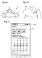
- FIG. 1A is a perspective view illustrating an embodiment of an electrocardiographic transmitter according to the present invention
- FIG. 1B is an explanatory diagram illustrating an example of a state in which the electrocardiographic transmitter is mounted on a chest of a subject
- FIG. 1C is an explanatory diagram showing an example of a state in which an electrocardiogram is displayed on a display of the terminal.
- 2A is a plan view
- FIG. 2B is a bottom view showing a state where an electrode pad is removed, showing an example of an external appearance of a main body of the electrocardiographic transmitter.
- FIG. 2 is a block diagram illustrating an example of an electrical configuration of an electrocardiographic transmitter. It is a lineblock diagram showing one embodiment of an electrocardiogram measurement system concerning the present invention.
- FIG. 9 is a graph illustrating an example of an electrocardiogram waveform
- FIG. 9B is a graph illustrating an example of a synchronization pulse of the electrocardiogram waveform.
- 11 is a flowchart illustrating still another example of the operation of the electrocardiographic transmitter and the terminal.
- 5 is a flowchart illustrating an example of the operation of the heart rate monitor and the terminal.
- FIG. 1A is a perspective view showing an embodiment of an electrocardiographic transmitter 1 according to the present invention.
- FIG. 1B is an explanatory diagram illustrating an example of a state in which the electrocardiographic transmitter 1 is mounted on the chest of the subject PA.
- FIG. 1C is an explanatory diagram illustrating an example of a state in which an electrocardiogram is displayed on the display 51 of the terminal 50.
- a power switch 11 is provided on the main body 10 of the electrocardiographic transmitter 1, and three electrode pads 2, 3, 4 can be mounted on the back side of the main body 10.
- Such an electrocardiographic transmitter 1 is mounted so that the electrode pads 2, 3, and 4 are electrically connected to the chest of the subject PA, so that an electrocardiographic signal can be measured.
- the external shape of the electrocardiographic transmitter 1 is not limited at all, as long as the electrocardiographic signal of the subject PA can be measured.
- the electrode pads 2, 3, and 4 cannot be attached to and detached from the main body 10. It may have a body shape, and the number of electrode pads may be two or three or more.
- the electrocardiographic transmitter 1 is, for example, Bluetooth (registered trademark) (Near Field Communication), NFC (Near Field Communication), personal area network (Personal Area Network: PAN), wireless LAN (Local Area Network), WiFi ( It is wirelessly connected to the terminal 50 via a wireless communication standard that assumes a relatively short distance such as Wireless Fidelity.
- Bluetooth registered trademark
- NFC Near Field Communication
- PAN Personal Area Network
- PAN Personal Area Network
- wireless LAN Local Area Network
- WiFi It is wirelessly connected to the terminal 50 via a wireless communication standard that assumes a relatively short distance such as Wireless Fidelity.
- the terminal 50 includes, for example, a smartphone, a handheld computer, a tablet PC, a desktop PC, and the like, and various software can be installed therein. Among them, by installing dedicated software specialized for the electrocardiographic measurement system according to the present invention, Receives an electrocardiographic signal wirelessly transmitted from the electrocardiographic transmitter 1, performs signal processing, and stores the electrocardiogram and various electrocardiographic parameters (for example, the respiratory rate RR and the heart rate HR) of the subject PA in a memory. Or display on the display 51 or transfer to an external host device (not shown).
- the terminal 50 wirelessly communicates with the host device via a wireless communication standard that assumes a relatively long distance, such as a wireless LAN (Local Area Network), WiFi (Wireless Fidelity), 3G, 4G (LTE), 5G, or the Internet. Connected.
- a wireless communication standard that assumes a relatively long distance, such as a wireless LAN (Local Area Network), WiFi (Wireless Fidelity), 3G, 4G (LTE), 5G, or the Internet. Connected.
- FIG. 2A and 2B show an example of the external appearance of the main body 10 of the electrocardiographic transmitter 1
- FIG. 2A is a plan view
- FIG. 2B is a bottom view showing a state in which electrode pads are removed.
- the main body 10 of the electrocardiographic transmitter 1 has a generally triangular shape with rounded corners, and a slide-type power switch 11 is provided on a side surface.
- terminals 12, 13, and 14 electrically connected to the electrode pads 2, 3, and 4 are provided on the bottom surface, and the electrode pads 2, 13, and 14 are provided near the terminals 12, 13, and 14, respectively.
- a pair of fasteners 12a, 13a, 14a mechanically connected to 3, 4 respectively are provided.
- a battery cover 15 for storing a battery (for example, a button-type battery) is provided at the center of the bottom surface.
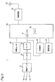
- FIG. 3 is a block diagram showing an example of an electrical configuration of the electrocardiographic transmitter 1.
- the electrocardiographic transmitter 1 includes a differential amplifier 21, a filter 22, an amplifier 23, and an R-wave detection circuit 24 connected to terminals 12, 13, and 14 as an electrocardiogram signal detection circuit. It includes a sensor 25, a CPU (central processing unit) 30 having a built-in A / D (analog-digital) converter 31 and a memory 32, a wireless communication circuit 26, an antenna 27, a power supply circuit 33, and the like.
- the differential amplifier 21 has a function of detecting an electrocardiographic signal by amplifying a difference between a potential generated at the electrode pad 2 and a potential generated at the electrode pad 4 using a potential generated at the electrode pad 3 located at the center as a ground potential. Have. Thereby, the in-phase component which is noise can be suppressed, and the negative-phase component which is signal can be amplified.
- the filter 22 includes a high-pass filter that suppresses low-frequency noise such as drift noise, a low-pass filter that suppresses high-frequency noise such as electromyogram signals, and a notch filter that suppresses specific frequency components such as commercial power supply noise. .
- the amplifier 23 has a function of amplifying the electrocardiographic signal and matching it with the input range of the A / D converter 31.
- the A / D converter 31 converts the electrocardiographic signal into a digital signal, and the digital signal is stored in the memory 32.
- the R-wave detection circuit 24 detects the position of the R-wave having the steepest peak in the electrocardiogram waveform (FIG. 9A), generates a synchronization pulse SYN (FIG. 9B) thereof, and provides it to the CPU 30. Based on the detected position of the R wave, the CPU 30 calculates various electrocardiographic parameters such as RR (millisecond: ms), which is the peak interval of the R wave, and heart rate HR (beats / minute: bpm) per unit time. Can be calculated. The CPU 30 can also wirelessly transmit the synchronization pulse SYN synchronized with the R wave to the terminal 50 via the wireless communication circuit 26.
- RR millisecond: ms
- HR heart rate
- the vibration sensor 25 includes a three-axis acceleration sensor, detects the respiration rate, the number of steps, the activity level, and the like of the subject PA, and provides the detected information to the CPU 30 via the A / D converter 31.
- the CPU 30 operates according to a preset program, and has a function of controlling signal processing such as an electrocardiographic signal and the operation of the entire apparatus.
- the wireless communication circuit 26 modulates a digital signal such as an electrocardiogram signal or a communication command of the CPU 30 into a high-frequency signal or converts a high-frequency signal received from the terminal 50 into a digital signal according to the above-described wireless communication standard such as Bluetooth (registered trademark). It has the function of demodulating.
- a digital signal such as an electrocardiogram signal or a communication command of the CPU 30 into a high-frequency signal or converts a high-frequency signal received from the terminal 50 into a digital signal according to the above-described wireless communication standard such as Bluetooth (registered trademark). It has the function of demodulating.
- the antenna 27 has a function of transmitting a high-frequency signal from the wireless communication circuit 26 and a function of receiving a high-frequency signal from the terminal 50.
- the power supply circuit 33 includes the power switch 11, a battery, and the like.
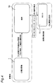
- FIG. 4 is a configuration diagram showing an embodiment of an electrocardiographic measurement system according to the present invention.
- the electrocardiographic measurement system includes the above-described electrocardiographic transmitter 1, a terminal 50 that wirelessly communicates with the electrocardiographic transmitter 1, and a host device 70 that wirelessly communicates with the terminal 50.
- the electrocardiographic transmitter 1 and the terminal 50 are installed near a patient, while the host device 70 is installed near a medical worker usually waiting at a location remote from the patient.
- the electrocardiographic transmitter 1 statistically processes an electrocardiographic signal and calculates an average value HRav of the heart rate HR within a predetermined time.
- the electrocardiographic transmitter 1 continuously transmits electrocardiogram data based on the electrocardiographic signal to the terminal 50.
- the terminal 50 receives the electrocardiogram data and transfers it to the host device 70 as it is.
- the host device 70 saves the transferred electrocardiogram data and provides it for diagnosis of a medical worker.
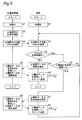
- FIG. 5 is a flowchart showing an example of the operation of the electrocardiographic transmitter 1 and the terminal 50.
- the terminal 50 determines whether the average value HRav is normal or abnormal.
- initialization is performed in step a1
- the interval for calculating the average value HRav of the heart rate HR is initially set. Is set.
- initialization is performed in step b1.
- the upper limit and lower limit of the normal range of the average value HRav of the heart rate HR, the threshold value of the non-transmission time of the electrocardiogram data, the electrocardiogram Initially, a data amount of a partial transmission of data is set.
- at least the upper and lower limits of the normal range of the average value HRav of the heart rate HR and the threshold value of the non-transmission time of the electrocardiogram data are arbitrary, for example, by the subject PA or a medical worker. May be set by In the case of Bluetooth (registered trademark), communication between the electrocardiographic transmitter 1 and the terminal 50 is established during initialization and data transmission (the same applies to other flowcharts).
- the electrocardiographic transmitter 1 starts measuring the electrocardiographic signal in step a2, calculates an average value HRav of the heart rate HR within a predetermined time (for example, one minute) in step a3, and sends the average value HRav to the terminal 50. Send.
- the terminal 50 receives the average value HRav of the heart rate HR transmitted from the electrocardiographic transmitter 1 in step b2, and then determines in step b3 whether the average value HRav is within a normal range (for example, 30 to 160 bpm). Is determined. If the average value HRav is within the normal range, the process returns to step b2 via step b6 (details will be described later). Thus, when the average value HRav is normal, the subject PA can be judged to be in a lucrative state, so that the power required for data transmission can be saved by not transmitting the electrocardiogram data having a huge data amount to the terminal 50.
- a normal range for example, 30 to 160 bpm
- step b3 if the average value HRav is out of the normal range in step b3, the subject PA can be determined to be in a serious condition, and the process proceeds to step b4, and the terminal 50 transmits the electrocardiogram data to the electrocardiogram transmission. Request to machine 1.
- the ECG transmitter 1 After receiving the ECG data request command in step a4, the ECG transmitter 1 continuously transmits the ECG data based on the ECG signal to the terminal 50.
- the terminal 50 receives the electrocardiogram data transmitted continuously in step b5, and transfers it to the host device 70 as it is. In this way, when the average value HRav is abnormal, it becomes possible to provide the medical staff with all the electrocardiogram data of the subject PA.
- step b6 will be described.
- the terminal 50 determines whether or not the non-transmission time of the electrocardiogram data has exceeded a predetermined time T1 (for example, one hour) in step b6. If the untransmitted time of the electrocardiogram data exceeds the time T1, the process proceeds to step b7, and the terminal 50 requests the electrocardiographic transmitter 1 to transmit a part (for example, 10 beats) of the electrocardiogram data. . After receiving the ECG data request command in step a5, the ECG transmitter 1 transmits only a part of the ECG data to the terminal 50.
- a predetermined time T1 for example, one hour
- the terminal 50 receives a part of the electrocardiogram data in step b8 and transfers it to the host device 70 as it is, and then returns to step b2. In this way, the medical worker can simply diagnose the electrocardiogram of the subject PA.
- the electrocardiographic transmitter 1 calculates the average value HRav of the heart rate HR.
- the biological signal information such as the number of R waves measured by the electrocardiographic transmitter 1 is transmitted to the terminal 50.
- software in the terminal 50 can calculate the average value HRav of the heart rate HR.
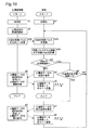
- FIG. 6 is a flowchart showing another example of the operation of the electrocardiographic transmitter 1 and the terminal 50.
- the electrocardiographic transmitter 1 determines whether the average value HRav is normal or abnormal will be described.
- initialization is performed in step c1, for example, the interval for calculating the average value HRav of the heart rate HR, the heart rate
- the upper limit and the lower limit of the normal range of the average value HRav of the HR are initially set.
- step c1 When the dedicated software installed in the terminal 50 is started, initialization is performed in step c1, and for example, a threshold value of the non-transmission time of the electrocardiogram data, a data amount of a partial transmission of the electrocardiogram data, and the like are initialized.
- a threshold value of the non-transmission time of the electrocardiogram data For example, a data amount of a partial transmission of the electrocardiogram data, and the like are initialized.
- the normal range of the average value HRav of the heart rate HR can also be initialized by inputting it at the terminal 50 and transmitting it to the electrocardiographic transmitter 1.
- the electrocardiographic transmitter 1 starts measuring an electrocardiographic signal in step c2, calculates an average value HRav of the heart rate HR within a predetermined time (for example, 1 minute) in step c3, Send.
- the terminal 50 receives the average value HRav of the heart rate HR transmitted from the electrocardiographic transmitter 1 in step d2.
- step c4 the electrocardiographic transmitter 1 determines whether or not the average value HRav is within a normal range (for example, 30 to 160 bpm). If the average value HRav is within the normal range, the process returns to step c3. Thus, when the average value HRav is normal, the subject PA can be judged to be in a lucrative state, so that the power required for data transmission can be saved by not transmitting the electrocardiogram data having a huge data amount to the terminal 50.
- a normal range for example, 30 to 160 bpm
- step c4 when the average value HRav is out of the normal range in step c4, the subject PA can be determined to be in a serious condition, and the process proceeds to step c5, where the electrocardiographic transmitter 1 determines the average heart rate HR.
- the terminal 50 is notified that the value HRav is abnormal.
- the terminal 50 requests the electrocardiogram transmitter 1 to transmit electrocardiogram data in step d4.
- the electrocardiogram transmitter 1 After receiving the request command for the electrocardiogram data in step c6, the electrocardiogram transmitter 1 continuously transmits electrocardiogram data based on the electrocardiogram signal to the terminal 50.
- the terminal 50 receives the electrocardiogram data continuously transmitted in step d5, and transfers it to the host device 70 as it is. In this way, when the average value HRav is abnormal, it becomes possible to provide the medical staff with all the electrocardiogram data of the subject PA.
- step d3 will be described.
- the terminal 50 determines in step d3 whether the untransmitted time of the electrocardiogram data has exceeded a predetermined time T1 (for example, one hour).
- a predetermined time T1 for example, one hour.
- the process proceeds to step d6, and the terminal 50 requests the electrocardiographic transmitter 1 to transmit a part (for example, 10 beats) of the electrocardiogram data.
- the electrocardiographic transmitter 1 After receiving the request command for the electrocardiogram data in step c7, the electrocardiographic transmitter 1 transmits only a part of the electrocardiogram data to the terminal 50.
- the terminal 50 receives a part of the electrocardiogram data in step d7 and transfers it to the host device 70 as it is, and then returns to step d2. In this way, the medical worker can simply diagnose the electrocardiogram of the subject PA.
- the electrocardiographic transmitter 1 calculates the average value HRav of the heart rate HR
- the biological signal information such as the number of R waves measured by the electrocardiographic transmitter 1 is transmitted to the terminal 50
- the average value HRav of the heart rate HR can be calculated by software in the terminal 50.
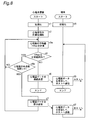
- FIG. 7 is a flowchart showing still another example of the operation of the electrocardiographic transmitter 1 and the terminal 50.
- step d2 is omitted from the flowchart of FIG. 6, and instead of step c3, the average value HRav of the heart rate HR within a predetermined time (for example, one minute) is calculated, but data transmission is omitted.
- Step c3a is performed.
- the electrocardiographic transmitter 1 determines the threshold value of the average value HRav in the next step c4, but does not transmit anything to the terminal 50 when the average value HRav is normal.
- partial transmission of the electrocardiogram data is performed (step c7). As a result, the frequency of data communication is reduced, thereby reducing power consumption and extending the life of the battery.
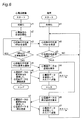
- FIG. 8 is a flowchart showing still another example of the operation of the electrocardiographic transmitter 1 and the terminal 50.
- the electrocardiographic transmitter 1 determines whether the average value HRav is normal or abnormal, and also determines the non-transmission time of the electrocardiogram data.
- initialization is performed in step c1, for example, the interval for calculating the average value HRav of the heart rate HR, the heart rate
- the upper limit and the lower limit of the normal range of the average value HRav of the HR are initially set.
- step c1 When the dedicated software installed in the terminal 50 is started, initialization is performed in step c1, and for example, a threshold value of the non-transmission time of the electrocardiogram data, a data amount of a partial transmission of the electrocardiogram data, and the like are initialized.
- a threshold value of the non-transmission time of the electrocardiogram data For example, a data amount of a partial transmission of the electrocardiogram data, and the like are initialized.
- the normal range of the average value HRav of the heart rate HR can also be initialized by inputting it at the terminal 50 and transmitting it to the electrocardiographic transmitter 1.
- the electrocardiographic transmitter 1 starts measuring the electrocardiographic signal in step c2, and calculates an average value HRav of the heart rate HR within a predetermined time (for example, one minute) in step c3a. Is not performed.
- step c4 the electrocardiographic transmitter 1 determines whether or not the average value HRav is within a normal range (for example, 30 to 160 bpm). If the average value HRav is within the normal range, the process returns to step c3a via step c4a (details will be described later). Thus, when the average value HRav is normal, the subject PA can be judged to be in a lucrative state, so that the power required for data transmission can be saved by not transmitting the electrocardiogram data having a huge data amount to the terminal 50.
- a normal range for example, 30 to 160 bpm
- step c4 the electrocardiographic transmitter 1 determines based on the electrocardiographic signal.
- the ECG data is continuously transmitted to the terminal 50.
- the terminal 50 receives the electrocardiogram data continuously transmitted in step d5, and transfers it to the host device 70 as it is. In this way, when the average value HRav is abnormal, it becomes possible to provide the medical staff with all the electrocardiogram data of the subject PA.
- step c4a will be described.
- the electrocardiographic transmitter 1 determines whether or not the untransmitted time of the electrocardiogram data has exceeded a predetermined time T1 (for example, one hour) in step c4a.
- a predetermined time T1 for example, one hour
- the process proceeds to step c7, and the electrocardiographic transmitter 1 transmits only a part (for example, 10 beats) of the electrocardiogram data to the terminal 50.
- the terminal 50 receives a part of the electrocardiogram data in step d7 and transfers it to the host device 70 as it is, and then returns after step d1. In this way, the medical worker can simply diagnose the electrocardiogram of the subject PA.
- FIG. 10 is a flowchart showing still another example of the operation of the electrocardiographic transmitter 1 and the terminal 50.
- the electrocardiographic transmitter 1 generates a synchronization pulse SYN of an electrocardiogram waveform and wirelessly transmits the synchronization pulse SYN
- the terminal 50 calculates an average value HRav from the synchronization pulse SYN, and determines whether it is normal or abnormal.
- initialization is performed in step a1, and, for example, an R-wave detection threshold is initialized.
- step b1 When the dedicated software installed in the terminal 50 is started, initialization is performed in step b1, for example, the interval for calculating the average value HRav of the heart rate HR, the upper limit of the normal range of the average value HRav of the heart rate HR, and The lower limit, the threshold value of the untransmitted time of the electrocardiogram data, the data amount of partial transmission of the electrocardiogram data, and the like are initialized.
- the upper and lower limits of the normal range of the average value HRav of the heart rate HR and the threshold value of the non-transmission time of the electrocardiogram data are arbitrary, for example, by the subject PA or a medical worker. May be set by
- the electrocardiographic transmitter 1 starts measuring an electrocardiographic signal in step a2, generates an R-wave synchronization pulse SYN in step a3a, and transmits it to the terminal 50.
- the terminal 50 receives the synchronization pulse SYN transmitted from the electrocardiographic transmitter 1 in step b2a, calculates an average value HRav of the heart rate HR from the synchronization pulse SYN in step b2b, and then calculates the average value HRav in step b3. It is determined whether the value HRav is within a normal range (for example, 30 to 160 bpm). If the average value HRav is within the normal range, the process returns to step b2 via step b6 (for details, see the description of steps b6 to b8 in FIG. 5). Thus, when the average value HRav is normal, the subject PA can be judged to be in a lucrative state, so that the power required for data transmission can be saved by not transmitting the electrocardiogram data having a huge data amount to the terminal 50.
- a normal range for example, 30 to 160 bpm
- step b3 if the average value HRav is out of the normal range in step b3, the subject PA can be determined to be in a serious condition, and the process proceeds to step b4, and the terminal 50 transmits the electrocardiogram data to the electrocardiogram transmission. Request to machine 1.
- the ECG transmitter 1 After receiving the ECG data request command in step a4, the ECG transmitter 1 continuously transmits the ECG data based on the ECG signal to the terminal 50.
- the terminal 50 receives the electrocardiogram data transmitted continuously in step b5, and transfers it to the host device 70 as it is. In this way, when the average value HRav is abnormal, it becomes possible to provide the medical staff with all the electrocardiogram data of the subject PA.
- the synchronization pulse SYN synchronized with the R wave is generated.
- the synchronization pulse SYN synchronized with the P wave, Q wave, S wave or T wave of the electrocardiogram waveform shown in FIG. 9A is generated. It is also possible.
- the heart rate meter has a function of measuring a heart rate by optically detecting a change in blood flow in a blood vessel instead of an electrocardiographic signal, and is attached to, for example, a chest, a wrist, an arm, or a neck.
- FIG. 11 is a flowchart illustrating an example of the operation of the heart rate monitor and the terminal. This flowchart omits steps c6, c7, d2 to d7 in the flowchart of FIG. 6, performs step c2a for starting heart rate measurement instead of step c2, and further performs predetermined time instead of step c3.
- the average value HRav of the heart rate HR within the period (for example, for one minute) is calculated, but step c3a in which data transmission is omitted is performed.
- the heart rate monitor determines the threshold value of the average value HRav in the next step c4. However, if the average value HRav is normal, it does not transmit anything to the terminal 50, and if the average value HRav is abnormal, Is notified to the terminal 50 (step c5), and the terminal 50 receives the abnormality notification of the average value HRav (step d10). This further reduces the frequency of data communication, thereby reducing power consumption and extending the life of the battery.
- the method of simply monitoring the state of the subject PA using the average value HRav of the heart rate HR as the statistic of the electrocardiographic signal has been exemplified.
- At least one parameter selected from the group consisting of the average value, the minimum value, the maximum value, the median value, the mode value, the variance, and the standard deviation of the heart rate within may be used.
- the average value is a value obtained by dividing the total value of data by the number of data.
- the minimum value is the smallest value in the data.
- the maximum value is the largest value in the data.
- the median value is a value located at the center when the data is arranged in ascending order. When the data is an even number, the average of two values near the center is calculated.
- the mode is the value of the data with the highest frequency.
- the variance is the mean of the squares of the difference between the mean and the individual data. Standard deviation is the positive square root of the variance.
- the present invention is extremely useful industrially in that the heart condition of a subject can be monitored over a long period of time.
Abstract
1)心電送信機(1)は、心電信号を統計処理して、予め定めた時間内における心拍数HRの平均値HRavを計算する。心拍数HRの平均値HRavが異常である場合、心電送信機(1)は、心電信号に基づいた心電図データを端末(50)に連続送信する。2)端末(50)は、心電図データを受信して、そのままホスト装置(70)に転送する。3)ホスト装置(70)は、転送された心電図データを保存し、医療従事者の診断のために提供する。これにより被検者の心臓状態を長期間に渡って監視できる。
Description
本発明は、被検者の心臓状態を監視できる心電計測システムおよび該システムで使用される心電送信機に関する。
心臓疾患を有する被検者に、通信機能を備えた携帯型心電計を装着して、心電図データをリアルタイムで移動端末に連続送信し、さらにサーバーが、移動端末から送信される心電図データを受信し、そして被検者に不整拍動が発生した場合、サーバー上で不整拍動発生時刻をマーキングして医師の診断を促進するための心電図監視システムが提案されている(例えば、特許文献1)。
また、不整脈が発生した場合、被検者に装着された検出装置が、計測中の心電図内に不整脈を示す異常波形が含まれていることを検出して、検出信号を被検者の周囲の通信端末に向けて送信することによって、被検者の周囲の人に注意を促し、不整脈に対して迅速に対処するよう促すことができるアラームシステムが提案されている(例えば、特許文献2)。
特許文献1に係るシステムでは、携帯型心電計は心電図データをリアルタイムで移動端末に連続して送信しているため、消費電力が大きくなる傾向がある。消費電力の増大は、長期間(例えば、1ヶ月以上)連続して測定することの障壁となり、これを実現するためには、電池と電池を内蔵する携帯型心電計の大型化や重量増加が避けられない。長期間連続して身体へ装着される携帯型心電計の大型化や重量増加は、被検者にとって取扱いの不便に繋がる。
特許文献2に係るシステムでは、携帯型検出装置は、計測中の心電図内に不整脈を示す異常波形が含まれていることをリアルタイムで検出して、検出信号を使用者の周囲の通信端末に向けて送信している。そのため不整脈を検出するための信号処理やアルゴリズムが極めて複雑になり、同様に消費電力が大きくなる傾向がある。さらに、心電図を外部へ送信する機能がないため、医師が心電図を詳細に診断することはできない。
本発明の目的は、被検者の心臓状態を長期間に渡って監視できる心電計測システムを提供することである。
また本発明の目的は、消費電力が少なく、電池および装置の小型化、軽量化が図られる心電送信機を提供することである。
上記目的を達成するために、本発明は、心電信号を検出する心電信号検出回路、および心電信号を無線送信する無線通信回路を含み、被検者の身体に装着される装着型の心電送信機と、
前記心電送信機から無線送信される心電信号を受信する端末と、を備えた心電計測システムであって、
前記心電送信機は、心電信号を統計処理して統計量を演算し、該統計量を前記端末に送信し、
前記端末は、受信した前記統計量が予め定めた範囲外であるか否かを判断し、
前記心電送信機は、前記統計量が予め定めた範囲外である場合に心電信号に基づいた心電図データを前記端末に送信し、一方、前記統計量が予め定めた範囲内である場合には該心電図データを前記端末に送信しないことを特徴とする。
前記心電送信機から無線送信される心電信号を受信する端末と、を備えた心電計測システムであって、
前記心電送信機は、心電信号を統計処理して統計量を演算し、該統計量を前記端末に送信し、
前記端末は、受信した前記統計量が予め定めた範囲外であるか否かを判断し、
前記心電送信機は、前記統計量が予め定めた範囲外である場合に心電信号に基づいた心電図データを前記端末に送信し、一方、前記統計量が予め定めた範囲内である場合には該心電図データを前記端末に送信しないことを特徴とする。
また本発明は、心電信号を検出する心電信号検出回路、および心電信号を無線送信する無線通信回路を含み、被検者の身体に装着される装着型の心電送信機と、
前記心電送信機から無線送信される心電信号を受信する端末と、を備えた心電計測システムであって、
前記心電送信機は、心電信号を統計処理して統計量を演算し、該統計量が予め定めた範囲外であるか否かを判断し、前記統計量が予め定めた範囲外である場合に心電信号に基づいた心電図データを前記端末に送信し、一方、前記統計量が予め定めた範囲内である場合には該心電図データを前記端末に送信しないことを特徴とする。
前記心電送信機から無線送信される心電信号を受信する端末と、を備えた心電計測システムであって、
前記心電送信機は、心電信号を統計処理して統計量を演算し、該統計量が予め定めた範囲外であるか否かを判断し、前記統計量が予め定めた範囲外である場合に心電信号に基づいた心電図データを前記端末に送信し、一方、前記統計量が予め定めた範囲内である場合には該心電図データを前記端末に送信しないことを特徴とする。
また本発明は、心電信号を検出する心電信号検出回路、および心電信号を無線送信する無線通信回路を含み、被検者の身体に装着される装着型の心電送信機と、
前記心電送信機から無線送信される心電信号を受信する端末と、を備えた心電計測システムであって、
前記心電送信機は、心電信号に同期した同期信号を生成し、該同期信号を前記端末に送信し、
前記端末は、受信した同期信号から心電信号の統計量を演算し、該統計量が予め定めた範囲外であるか否かを判断し、
前記心電送信機は、前記統計量が予め定めた範囲外である場合に心電信号に基づいた心電図データを前記端末に送信し、一方、前記統計量が予め定めた範囲内である場合には該心電図データを前記端末に送信しないことを特徴とする。
前記心電送信機から無線送信される心電信号を受信する端末と、を備えた心電計測システムであって、
前記心電送信機は、心電信号に同期した同期信号を生成し、該同期信号を前記端末に送信し、
前記端末は、受信した同期信号から心電信号の統計量を演算し、該統計量が予め定めた範囲外であるか否かを判断し、
前記心電送信機は、前記統計量が予め定めた範囲外である場合に心電信号に基づいた心電図データを前記端末に送信し、一方、前記統計量が予め定めた範囲内である場合には該心電図データを前記端末に送信しないことを特徴とする。
本発明によれば、心電信号を統計処理して統計量を演算しているため、信号処理やアルゴリズムが簡素化できる。また、統計量が予め定めた範囲内(例えば、正常な範囲内)である場合には心電図データを端末に送信しないことによって、データ送信に要する電力を節約できる。そのため、消費電力が少なく、電池および装置の小型化、軽量化が図られ、被検者の心臓状態を長期間に渡って監視することが可能になる。
本発明において、前記端末から無線送信される心電図データを受信して保存するホスト装置をさらに備えることが好ましい。
本態様によれば、ホスト装置に心電図データが保存されるため、ホスト装置を心電送信機および端末から遠隔な場所に設置した場合でも、医師が被検者の心電図を遠隔的かつ詳細に診断することが可能になる。
本発明において、前記統計量は、予め定めた時間内における心拍数の平均値、最小値、最大値、メジアン値、最頻値、分散および標準偏差からなるグループから選択された少なくとも1つのパラメータであることが好ましい。
本態様によれば、これらの統計量は、簡素な信号処理やアルゴリズムで演算できるため、消費電力を低減できる。
本発明において、前記心電送信機は、前記統計量が予め定めた範囲内である場合でも、予め定めた時間間隔で心電図データの一部を前記端末に送信することが好ましい。
本態様によれば、統計量が予め定めた範囲内である場合でも、予め定めた時間間隔で心電図データの一部を端末に送信することによって、被検者の心電図を簡略的に診断することが可能になる。
また本発明は、心電信号を検出する心電信号検出回路と、
心電信号を外部の端末に無線送信する無線通信回路とを備え、被検者の身体に装着される装着型の心電送信機であって、
心電信号を統計処理して統計量を演算し、該統計量を前記端末に送信し、
前記統計量が予め定めた範囲外である場合に心電信号に基づいた心電図データを前記端末に送信し、一方、前記統計量が予め定めた範囲内である場合には該心電図データを前記端末に送信しないことを特徴とする。
心電信号を外部の端末に無線送信する無線通信回路とを備え、被検者の身体に装着される装着型の心電送信機であって、
心電信号を統計処理して統計量を演算し、該統計量を前記端末に送信し、
前記統計量が予め定めた範囲外である場合に心電信号に基づいた心電図データを前記端末に送信し、一方、前記統計量が予め定めた範囲内である場合には該心電図データを前記端末に送信しないことを特徴とする。
また本発明は、心電信号を検出する心電信号検出回路と、
心電信号を外部の端末に無線送信する無線通信回路とを備え、被検者の身体に装着される装着型の心電送信機であって、
心電信号を統計処理して統計量を演算し、該統計量が予め定めた範囲外であるか否かを判断し、前記統計量が予め定めた範囲外である場合に心電信号に基づいた心電図データを前記端末に送信し、一方、前記統計量が予め定めた範囲内である場合には該心電図データを前記端末に送信しないことを特徴とする。
心電信号を外部の端末に無線送信する無線通信回路とを備え、被検者の身体に装着される装着型の心電送信機であって、
心電信号を統計処理して統計量を演算し、該統計量が予め定めた範囲外であるか否かを判断し、前記統計量が予め定めた範囲外である場合に心電信号に基づいた心電図データを前記端末に送信し、一方、前記統計量が予め定めた範囲内である場合には該心電図データを前記端末に送信しないことを特徴とする。
また本発明は、
心電信号を検出する心電信号検出回路と、
心電信号を外部の端末に無線送信する無線通信回路とを備え、被検者の身体に装着される装着型の心電送信機であって、
心電信号に同期した同期信号を生成し、該同期信号を前記端末に送信し、
前記端末によって該同期信号から演算された心電信号の統計量が予め定めた範囲外である場合に心電信号に基づいた心電図データを前記端末に送信し、一方、前記統計量が予め定めた範囲内である場合には該心電図データを前記端末に送信しないことを特徴とする。
心電信号を検出する心電信号検出回路と、
心電信号を外部の端末に無線送信する無線通信回路とを備え、被検者の身体に装着される装着型の心電送信機であって、
心電信号に同期した同期信号を生成し、該同期信号を前記端末に送信し、
前記端末によって該同期信号から演算された心電信号の統計量が予め定めた範囲外である場合に心電信号に基づいた心電図データを前記端末に送信し、一方、前記統計量が予め定めた範囲内である場合には該心電図データを前記端末に送信しないことを特徴とする。
本発明によれば、心電信号を統計処理して統計量を演算しているため、信号処理やアルゴリズムが簡素化できる。また、統計量が予め定めた範囲内(例えば、正常な範囲内)である場合には心電図データを端末に送信しないことによって、データ送信に要する電力を節約できる。そのため、消費電力が少なく、電池および装置の小型化、軽量化が図られ、被検者の心臓状態を長期間に渡って監視することが可能になる。
本発明において、前記統計量は、予め定めた時間内における心拍数の平均値、最小値、最大値、メジアン値、最頻値、分散および標準偏差からなるグループから選択された少なくとも1つのパラメータであることが好ましい。
本態様によれば、これらの統計量は、簡素な信号処理やアルゴリズムで演算できるため、消費電力を低減できる。
本発明によれば、被検者の心臓状態を長期間に渡って監視できる心電計測システムを提供できる。また消費電力が少なく、電池および装置の小型化、軽量化が図られる心電送信機を提供できる。
以下、本発明の実施の形態について、図面を参照して具体的に説明する。
図1Aは、本発明に係る心電送信機1の一実施形態を示す斜視図である。図1Bは、心電送信機1が被検者PAの胸部に装着された状態の一例を示す説明図である。図1Cは、端末50のディスプレイ51に心電図が表示される状態の一例を示す説明図である。
心電送信機1の本体10には電源スイッチ11が設けられており、本体10の裏面側には3つの電極パッド2,3,4を装着することができる。こうした心電送信機1は、電極パッド2,3,4が被検者PAの胸部と電気的に接続されるように装着され、心電信号を計測することが可能になる。なお、被検者PAの心電信号を計測することが可能であれば、心電送信機1の外観形状は何ら限定されず、例えば、電極パッド2,3,4は本体10と着脱できない一体型であってもよく、電極パッドの数は2つ乃至3つ以上であってもよい。心電送信機1は、例えば、ブルートゥース(登録商標)(Bluetooth(登録商標))、NFC(Near Field Communication)、パーソナルエリアネットワーク(Personal Area Network: PAN)、無線LAN(Local Area Network)、WiFi(Wireless Fidelity)など、比較的近距離を想定した無線通信規格を経由して端末50と無線接続される。
端末50は、例えば、スマートフォン、ハンドヘルドコンピュータ、タブレットPC、デスクトップPCなどで構成され、種々のソフトウェアがインストール可能であり、そのうち本発明に係る心電計測システムに特化した専用ソフトウェアをインストールすることによって、心電送信機1から無線送信される心電信号を受信して信号処理を施し、被検者PAの心電図や各種心電パラメータ(例えば、呼吸数RR、心拍数HRなど)をメモリに保存したり、ディスプレイ51に表示したり、外部のホスト装置(不図示)に転送することができる。端末50は、例えば、無線LAN(Local Area Network)、WiFi(Wireless Fidelity)、3G、4G(LTE)、5G、インターネットなど、比較的遠距離を想定した無線通信規格を経由してホスト装置と無線接続される。
図2Aと図2Bは、心電送信機1の本体10の外観の一例を示すものであり、図2Aは平面図、図2Bは電極パッドを取り外した状態を示す底面図である。
心電送信機1の本体10は、全体的に隅丸三角形状をなし、側面にはスライド式の電源スイッチ11が設けられる。図2Bに示すように、底面には電極パッド2,3,4と電気的にそれぞれ接続される端子12,13,14が設けられ、各端子12,13,14の近傍には電極パッド2,3,4と機械的にそれぞれ接続される一対のファスナ12a,13a,14aが設けられる。底面の中央には電池(例えば、ボタン型電池)を収納するための電池カバー15が設けられる。
図3は、心電送信機1の電気的構成の一例を示すブロック図である。心電送信機1は、心電信号検出回路として、端子12,13,14と接続された差動アンプ21と、フィルタ22と、アンプ23と、R波検出回路24とを備え、さらに、振動センサ25と、A/D(アナログデジタル)変換器31およびメモリ32を内蔵したCPU(中央処理装置)30と、無線通信回路26と、アンテナ27と、電源回路33などを備える。
差動アンプ21は、中央に位置する電極パッド3で生ずる電位をグランド電位として、電極パッド2で生ずる電位と電極パッド4で生ずる電位との差分を増幅して、心電信号を検出する機能を有する。これによりノイズである同相成分を抑制し、信号である逆相成分を増幅できる。
フィルタ22は、ドリフトノイズなどの低周波ノイズを抑制するハイパスフィルタと、筋電図信号などの高周波ノイズを抑制するローパスフィルタと、商用電源ノイズなどの特定の周波数成分を抑制するノッチフィルタなどを備える。
アンプ23は、心電信号を増幅して、A/D変換器31の入力レンジに整合させる機能を有する。A/D変換器31は、心電信号をデジタル信号に変換し、デジタル信号はメモリ32に保存される。
R波検出回路24は、心電図波形(図9A)のうち最も急峻なピークを有するR波の位置を検出して、その同期パルスSYN(図9B)を生成してCPU30に提供する。CPU30は、検出したR波の位置に基づいて、R波のピーク間隔であるRR(ミリ秒: ms)、単位時間当りの心拍数HR(拍動/分: bpm)などの各種心電パラメータを算出できる。CPU30はまた、R波に同期した同期パルスSYNを無線通信回路26を経由して端末50に無線送信することも可能である。
振動センサ25は、3軸加速度センサを備え、被検者PAの呼吸数、歩数、活動レベルなど検出して、A/D変換器31を介してCPU30に提供する。
CPU30は、予め設定されたプログラムに従って動作し、心電信号などの信号処理および装置全体の動作を制御する機能を有する。
無線通信回路26は、ブルートゥース(登録商標)など、上述した無線通信規格に従って、心電信号などのデジタル信号やCPU30の通信コマンドを高周波信号に変調したり、端末50から受信した高周波信号をデジタル信号に復調する機能を有する。
アンテナ27は、無線通信回路26からの高周波信号を送信したり、端末50からの高周波信号を受信する機能を有する。
電源回路33は、電源スイッチ11、電池などを備える。
図4は、本発明に係る心電計測システムの一実施形態を示す構成図である。心電計測システムは、上述した心電送信機1と、心電送信機1と無線通信する端末50と、端末50と無線通信するホスト装置70とを備える。心電送信機1および端末50は、患者の近くに設置され、一方、ホスト装置70は、通常は患者から遠隔の場所に待機している医療従事者の近くに設置される。
図4を参照して、システム全体の動作について説明する。最初に、1)心電送信機1は、心電信号を統計処理して、予め定めた時間内における心拍数HRの平均値HRavを計算する。心拍数HRの平均値HRavが異常である場合、心電送信機1は、心電信号に基づいた心電図データを端末50に連続送信する。2)端末50は、心電図データを受信して、そのままホスト装置70に転送する。3)ホスト装置70は、転送された心電図データを保存し、医療従事者の診断のために提供する。
図5は、心電送信機1および端末50の動作の一例を示すフローチャートである。ここでは、端末50が平均値HRavの正常または異常を判断する場合を説明する。心電送信機1を被検者PAの胸部に装着して、電源スイッチ11をオンにすると、ステップa1において初期化が行われ、例えば、心拍数HRの平均値HRavを計算する間隔などが初期設定される。また、端末50にインストールされた専用ソフトウェアを起動すると、ステップb1において初期化が行われ、例えば、心拍数HRの平均値HRavの正常範囲の上限および下限、心電図データの未送信時間の閾値、心電図データの一部送信のデータ量などが初期設定される。これら初期設定された数値のうち、少なくとも、心拍数HRの平均値HRavの正常範囲の上限および下限、心電図データの未送信時間の閾値は、例えば、被検者PAや医療従事者など人によって任意で設定される場合がある。なお、ブルートゥース(登録商標)の場合、初期化およびデータ送信の際に心電送信機1と端末50との間の通信確立が行われる(他のフローチャートも同様)。
次に心電送信機1は、ステップa2において心電信号の計測を開始し、ステップa3において予め定めた時間内(例えば、1分間)における心拍数HRの平均値HRavを計算し、端末50に送信する。
端末50は、ステップb2において心電送信機1から送信された心拍数HRの平均値HRavを受信し、続いてステップb3において平均値HRavが正常範囲(例えば、30~160bpm)内であるか否かが判断される。平均値HRavが正常範囲内であれば、ステップb6(詳細は後述する)を経由してステップb2に戻る。こうして平均値HRavが正常である場合、被検者PAは小康状態であると判断できるため、膨大なデータ量を有する心電図データを端末50に送信しないことによって、データ送信に要する電力を節約できる。
一方、ステップb3において平均値HRavが正常範囲外である場合、被検者PAは重篤状態であると判断できるため、ステップb4に移行して、端末50は、心電図データの送信を心電送信機1に要求する。心電送信機1は、ステップa4において心電図データの要求命令を受信した後、心電信号に基づいた心電図データを端末50に連続的に送信する。端末50は、ステップb5において連続的に送信される心電図データを受信し、そのままホスト装置70に転送する。こうして平均値HRavが異常である場合、被検者PAの心電図データをもれなく医療従事者に提供することが可能になる。
次にステップb6について説明する。ここでは、平均値HRavが正常範囲内であっても、心電図データの一部を端末50に送信する。即ち、端末50は、ステップb6において心電図データの未送信時間が予め定めた時間T1(例えば、1時間)を超えたか否かを判断する。心電図データの未送信時間が時間T1を超えた場合、ステップb7に移行して、端末50は、心電図データの一部(例えば、10拍分)を送信することを心電送信機1に要求する。心電送信機1は、ステップa5において心電図データの要求命令を受信した後、心電図データの一部だけを端末50に送信する。続いて端末50は、ステップb8において心電図データの一部を受信し、そのままホスト装置70に転送した後、ステップb2に戻る。こうして医療従事者は、被検者PAの心電図を簡略的に診断することが可能になる。
なお、ここでは心電送信機1が心拍数HRの平均値HRavを計算する場合を説明したが、心電送信機1が計測したR波の数等の生体信号情報を端末50に送信し、端末50で受信した生体信号情報を用いて、端末50内のソフトウェアが心拍数HRの平均値HRavを算出することもできる。
図6は、心電送信機1および端末50の動作の他の例を示すフローチャートである。ここでは、心電送信機1が平均値HRavの正常または異常を判断する場合を説明する。心電送信機1を被検者PAの胸部に装着して、電源スイッチ11をオンにすると、ステップc1において初期化が行われ、例えば、心拍数HRの平均値HRavを計算する間隔、心拍数HRの平均値HRavの正常範囲の上限および下限などが初期設定される。また、端末50にインストールされた専用ソフトウェアを起動すると、ステップc1において初期化が行われ、例えば、心電図データの未送信時間の閾値、心電図データの一部送信のデータ量などが初期設定される。なお、心拍数HRの平均値HRavの正常範囲は、端末50で入力し、心電送信機1に送信することによって初期設定することも可能である。
次に心電送信機1は、ステップc2において心電信号の計測を開始し、ステップc3において予め定めた時間内(例えば、1分間)における心拍数HRの平均値HRavを計算し、端末50に送信する。端末50は、ステップd2において心電送信機1から送信された心拍数HRの平均値HRavを受信する。
続いて心電送信機1は、ステップc4において平均値HRavが正常範囲(例えば、30~160bpm)内であるか否かが判断される。平均値HRavが正常範囲内であれば、ステップc3に戻る。こうして平均値HRavが正常である場合、被検者PAは小康状態であると判断できるため、膨大なデータ量を有する心電図データを端末50に送信しないことによって、データ送信に要する電力を節約できる。
一方、ステップc4において平均値HRavが正常範囲外である場合、被検者PAは重篤状態であると判断できるため、ステップc5に移行して、心電送信機1は、心拍数HRの平均値HRavが異常であることを端末50に通知する。端末50は、ステップd4において心電図データの送信を心電送信機1に要求する。心電送信機1は、ステップc6において心電図データの要求命令を受信した後、心電信号に基づいた心電図データを端末50に連続的に送信する。端末50は、ステップd5において連続的に送信される心電図データを受信し、そのままホスト装置70に転送する。こうして平均値HRavが異常である場合、被検者PAの心電図データをもれなく医療従事者に提供することが可能になる。
次にステップd3について説明する。ここでは、平均値HRavが正常範囲内であっても、心電図データの一部を端末50に送信する。即ち、端末50は、ステップd3において心電図データの未送信時間が予め定めた時間T1(例えば、1時間)を超えたか否かを判断する。心電図データの未送信時間が時間T1を超えた場合、ステップd6に移行して、端末50は、心電図データの一部(例えば、10拍分)を送信することを心電送信機1に要求する。心電送信機1は、ステップc7において心電図データの要求命令を受信した後、心電図データの一部だけを端末50に送信する。続いて端末50は、ステップd7において心電図データの一部を受信し、そのままホスト装置70に転送した後、ステップd2に戻る。こうして医療従事者は、被検者PAの心電図を簡略的に診断することが可能になる。
なお、ここでは心電送信機1が心拍数HRの平均値HRavを計算する場合を説明したが、心電送信機1が計測したR波の数等の生体信号情報を端末50に送信し、端末50が受信した生体信号情報を用いて、端末50内のソフトウェアで心拍数HRの平均値HRavを算出することもできる。
図7は、心電送信機1および端末50の動作のさらに他の例を示すフローチャートである。このフローチャートは、図6のフローチャートにおいてステップd2を省略し、ステップc3の代わりに、予め定めた時間内(例えば、1分間)における心拍数HRの平均値HRavを計算するが、データ送信を省略したステップc3aを行う。心電送信機1は、次のステップc4において平均値HRavの閾値判断を行うが、平均値HRavが正常である場合には端末50に何も送信しない。但し、心電図データの部分送信は実施する(ステップc7)。これによりデータ通信の頻度が減少して、消費電力の削減、電池の長寿命化が図られる。
図8は、心電送信機1および端末50の動作のさらに他の例を示すフローチャートである。ここでは、心電送信機1が平均値HRavの正常または異常を判断するとともに、心電図データの未送信時間も判断する場合を説明する。心電送信機1を被検者PAの胸部に装着して、電源スイッチ11をオンにすると、ステップc1において初期化が行われ、例えば、心拍数HRの平均値HRavを計算する間隔、心拍数HRの平均値HRavの正常範囲の上限および下限などが初期設定される。また、端末50にインストールされた専用ソフトウェアを起動すると、ステップc1において初期化が行われ、例えば、心電図データの未送信時間の閾値、心電図データの一部送信のデータ量などが初期設定される。なお、心拍数HRの平均値HRavの正常範囲は、端末50で入力し、心電送信機1に送信することによって初期設定することも可能である。
次に心電送信機1は、ステップc2において心電信号の計測を開始し、ステップc3aにおいて予め定めた時間内(例えば、1分間)における心拍数HRの平均値HRavを計算するが、データ送信は行わない。
続いて心電送信機1は、ステップc4において平均値HRavが正常範囲(例えば、30~160bpm)内であるか否かが判断される。平均値HRavが正常範囲内であれば、ステップc4a(詳細は後述する)を経由してステップc3aに戻る。こうして平均値HRavが正常である場合、被検者PAは小康状態であると判断できるため、膨大なデータ量を有する心電図データを端末50に送信しないことによって、データ送信に要する電力を節約できる。
一方、ステップc4において平均値HRavが正常範囲外である場合、被検者PAは重篤状態であると判断できるため、ステップc6に移行して、心電送信機1は、心電信号に基づいた心電図データを端末50に連続的に送信する。端末50は、ステップd5において連続的に送信される心電図データを受信し、そのままホスト装置70に転送する。こうして平均値HRavが異常である場合、被検者PAの心電図データをもれなく医療従事者に提供することが可能になる。
次にステップc4aについて説明する。ここでは、平均値HRavが正常範囲内であっても、心電図データの一部を端末50に送信する。即ち、心電送信機1は、ステップc4aにおいて心電図データの未送信時間が予め定めた時間T1(例えば、1時間)を超えたか否かを判断する。心電図データの未送信時間が時間T1を超えた場合、ステップc7に移行して、心電送信機1は、心電図データの一部(例えば、10拍分)だけを端末50に送信する。続いて端末50は、ステップd7において心電図データの一部を受信し、そのままホスト装置70に転送した後、ステップd1の後に戻る。こうして医療従事者は、被検者PAの心電図を簡略的に診断することが可能になる。
図10は、心電送信機1および端末50の動作のさらに他の例を示すフローチャートである。ここでは、心電送信機1が心電図波形の同期パルスSYNを生成して無線送信し、端末50がこの同期パルスSYNから平均値HRavを計算し、その正常または異常を判断する場合を説明する。心電送信機1を被検者PAの胸部に装着して、電源スイッチ11をオンにすると、ステップa1において初期化が行われ、例えば、R波の検出閾値などが初期設定される。また、端末50にインストールされた専用ソフトウェアを起動すると、ステップb1において初期化が行われ、例えば、心拍数HRの平均値HRavを計算する間隔、心拍数HRの平均値HRavの正常範囲の上限および下限、心電図データの未送信時間の閾値、心電図データの一部送信のデータ量などが初期設定される。これら初期設定された数値のうち、少なくとも、心拍数HRの平均値HRavの正常範囲の上限および下限、心電図データの未送信時間の閾値は、例えば、被検者PAや医療従事者など人によって任意で設定される場合がある。
次に心電送信機1は、ステップa2において心電信号の計測を開始し、ステップa3aにおいてR波の同期パルスSYNを生成して端末50に送信する。
端末50は、ステップb2aにおいて心電送信機1から送信された同期パルスSYNを受信し、次にステップb2bにおいてこの同期パルスSYNから心拍数HRの平均値HRavを計算し、続いてステップb3において平均値HRavが正常範囲(例えば、30~160bpm)内であるか否かが判断される。平均値HRavが正常範囲内であれば、ステップb6(詳細は図5のステップb6~b8に関する説明を参照)を経由してステップb2に戻る。こうして平均値HRavが正常である場合、被検者PAは小康状態であると判断できるため、膨大なデータ量を有する心電図データを端末50に送信しないことによって、データ送信に要する電力を節約できる。
一方、ステップb3において平均値HRavが正常範囲外である場合、被検者PAは重篤状態であると判断できるため、ステップb4に移行して、端末50は、心電図データの送信を心電送信機1に要求する。心電送信機1は、ステップa4において心電図データの要求命令を受信した後、心電信号に基づいた心電図データを端末50に連続的に送信する。端末50は、ステップb5において連続的に送信される心電図データを受信し、そのままホスト装置70に転送する。こうして平均値HRavが異常である場合、被検者PAの心電図データをもれなく医療従事者に提供することが可能になる。
なお、ここではR波に同期した同期パルスSYNを生成する場合を例示したが、代替として、図9Aに示す心電図波形のP波、Q波、S波またはT波に同期した同期パルスSYNを生成することも可能である。
次に心電送信機1を応用した通信型の心拍計について説明する。心拍計は、心電信号の代わりに、血管内の血流量の変化を光学的に検出して心拍数を計測する機能を有し、例えば、胸、手首、腕、首などに装着される。図11は、心拍計および端末の動作の一例を示すフローチャートである。このフローチャートは、図6のフローチャートにおいてステップc6,c7,d2~d7を省略し、ステップc2の代わりに、心拍数の計測を開始するステップc2aを行い、さらにステップc3の代わりに、予め定めた時間内(例えば、1分間)における心拍数HRの平均値HRavを計算するが、データ送信を省略したステップc3aを行う。心拍計は、次のステップc4において平均値HRavの閾値判断を行うが、平均値HRavが正常である場合には端末50に何も送信せず、平均値HRavが異常である場合には、異常であることを端末50に通知し(ステップc5)、端末50は平均値HRavの異常通知を受信する(ステップd10)。これによりデータ通信の頻度がさらに減少して、消費電力の削減、電池の長寿命化が図られる。
上述の実施形態では、心電信号の統計量として心拍数HRの平均値HRavを用いて被検者PAの状態を簡易的に監視する手法を例示したが、こうした統計量は、予め定めた時間内における心拍数の平均値、最小値、最大値、メジアン値、最頻値、分散および標準偏差からなるグループから選択された少なくとも1つのパラメータを使用してもよい。なお、平均値は、データの合計値をデータ数で除算した値である。最小値は、データの中で最も小さな値である。最大値は、データの中で最も大きな値である。メジアン値は、データを小さい順に並べたとき中央に位置する値であり、データが偶数個の場合は中央に近い2つの値の平均をとる。最頻値は、度数が最も多く現れるデータの値である。分散は、平均値と個々のデータとの差の2乗の平均値である。標準偏差は、分散の正の平方根である。
本発明は、被検者の心臓状態を長期間に渡って監視できる点で、産業上極めて有用である。
1 心電送信機、 2,3,4 電極パッド、 10 本体、
11 電源スイッチ、 12,13,14 端子、
12a,13a,14a ファスナ、 15 電池カバー、
21 差動アンプ、 22 フィルタ、 23 アンプ、
24 R波検出回路、 25 振動センサ、 26 無線通信回路、
27 アンテナ、 30 CPU、 31 A/D変換器、
32 メモリ、 33 電源回路、 50 端末、
51 ディスプレイ、 70 ホスト装置、 PA 被検者、
SYN 同期パルス
11 電源スイッチ、 12,13,14 端子、
12a,13a,14a ファスナ、 15 電池カバー、
21 差動アンプ、 22 フィルタ、 23 アンプ、
24 R波検出回路、 25 振動センサ、 26 無線通信回路、
27 アンテナ、 30 CPU、 31 A/D変換器、
32 メモリ、 33 電源回路、 50 端末、
51 ディスプレイ、 70 ホスト装置、 PA 被検者、
SYN 同期パルス
Claims (10)
- 心電信号を検出する心電信号検出回路、および心電信号を無線送信する無線通信回路を含み、被検者の身体に装着される装着型の心電送信機と、
前記心電送信機から無線送信される心電信号を受信する端末と、を備えた心電計測システムであって、
前記心電送信機は、心電信号を統計処理して統計量を演算し、該統計量を前記端末に送信し、
前記端末は、受信した前記統計量が予め定めた範囲外であるか否かを判断し、
前記心電送信機は、前記統計量が予め定めた範囲外である場合に心電信号に基づいた心電図データを前記端末に送信し、一方、前記統計量が予め定めた範囲内である場合には該心電図データを前記端末に送信しないことを特徴とする心電計測システム。 - 心電信号を検出する心電信号検出回路、および心電信号を無線送信する無線通信回路を含み、被検者の身体に装着される装着型の心電送信機と、
前記心電送信機から無線送信される心電信号を受信する端末と、を備えた心電計測システムであって、
前記心電送信機は、心電信号を統計処理して統計量を演算し、該統計量が予め定めた範囲外であるか否かを判断し、前記統計量が予め定めた範囲外である場合に心電信号に基づいた心電図データを前記端末に送信し、一方、前記統計量が予め定めた範囲内である場合には該心電図データを前記端末に送信しないことを特徴とする心電計測システム。 - 心電信号を検出する心電信号検出回路、および心電信号を無線送信する無線通信回路を含み、被検者の身体に装着される装着型の心電送信機と、
前記心電送信機から無線送信される心電信号を受信する端末と、を備えた心電計測システムであって、
前記心電送信機は、心電信号に同期した同期信号を生成し、該同期信号を前記端末に送信し、
前記端末は、受信した同期信号から心電信号の統計量を演算し、該統計量が予め定めた範囲外であるか否かを判断し、
前記心電送信機は、前記統計量が予め定めた範囲外である場合に心電信号に基づいた心電図データを前記端末に送信し、一方、前記統計量が予め定めた範囲内である場合には該心電図データを前記端末に送信しないことを特徴とする心電計測システム。 - 前記端末から無線送信される心電図データを受信して保存するホスト装置をさらに備える請求項1~3のいずれかに記載の心電計測システム。
- 前記統計量は、予め定めた時間内における心拍数の平均値、最小値、最大値、メジアン値、最頻値、分散および標準偏差からなるグループから選択された少なくとも1つのパラメータである請求項1~3のいずれかに記載の心電計測システム。
- 前記心電送信機は、前記統計量が予め定めた範囲内である場合でも、予め定めた時間間隔で心電図データの一部を前記端末に送信する請求項1~3のいずれかに記載の心電計測システム。
- 心電信号を検出する心電信号検出回路と、
心電信号を外部の端末に無線送信する無線通信回路とを備え、被検者の身体に装着される装着型の心電送信機であって、
心電信号を統計処理して統計量を演算し、該統計量を前記端末に送信し、
前記統計量が予め定めた範囲外である場合に心電信号に基づいた心電図データを前記端末に送信し、一方、前記統計量が予め定めた範囲内である場合には該心電図データを前記端末に送信しないことを特徴とする心電送信機。 - 心電信号を検出する心電信号検出回路と、
心電信号を外部の端末に無線送信する無線通信回路とを備え、被検者の身体に装着される装着型の心電送信機であって、
心電信号を統計処理して統計量を演算し、該統計量が予め定めた範囲外であるか否かを判断し、前記統計量が予め定めた範囲外である場合に心電信号に基づいた心電図データを前記端末に送信し、一方、前記統計量が予め定めた範囲内である場合には該心電図データを前記端末に送信しないことを特徴とする心電送信機。 - 心電信号を検出する心電信号検出回路と、
心電信号を外部の端末に無線送信する無線通信回路とを備え、被検者の身体に装着される装着型の心電送信機であって、
心電信号に同期した同期信号を生成し、該同期信号を前記端末に送信し、
前記端末によって該同期信号から演算された心電信号の統計量が予め定めた範囲外である場合に心電信号に基づいた心電図データを前記端末に送信し、一方、前記統計量が予め定めた範囲内である場合には該心電図データを前記端末に送信しないことを特徴とする心電送信機。 - 前記統計量は、予め定めた時間内における心拍数の平均値、最小値、最大値、メジアン値、最頻値、分散および標準偏差からなるグループから選択された少なくとも1つのパラメータである請求項7~9のいずれかに記載の心電送信機。
Priority Applications (5)
| Application Number | Priority Date | Filing Date | Title |
|---|---|---|---|
| US17/258,031 US20210228077A1 (en) | 2018-07-06 | 2019-06-18 | Ecg measurement system and ecg transmitter |
| JP2020528772A JP7216092B2 (ja) | 2018-07-06 | 2019-06-18 | 心電計測システムおよび心電送信機 |
| CN201980045037.7A CN112384142A (zh) | 2018-07-06 | 2019-06-18 | 心电测量系统及心电发射器 |
| EP19830641.7A EP3818931A4 (en) | 2018-07-06 | 2019-06-18 | ECG MEASUREMENT SYSTEM AND ECG TRANSMITTER |
| US18/350,809 US20230346219A1 (en) | 2018-07-06 | 2023-07-12 | Ecg measurement system and ecg transmitter |
Applications Claiming Priority (2)
| Application Number | Priority Date | Filing Date | Title |
|---|---|---|---|
| JP2018129081 | 2018-07-06 | ||
| JP2018-129081 | 2018-07-06 |
Related Child Applications (2)
| Application Number | Title | Priority Date | Filing Date |
|---|---|---|---|
| US17/258,031 A-371-Of-International US20210228077A1 (en) | 2018-07-06 | 2019-06-18 | Ecg measurement system and ecg transmitter |
| US18/350,809 Division US20230346219A1 (en) | 2018-07-06 | 2023-07-12 | Ecg measurement system and ecg transmitter |
Publications (1)
| Publication Number | Publication Date |
|---|---|
| WO2020008864A1 true WO2020008864A1 (ja) | 2020-01-09 |
Family
ID=69060209
Family Applications (1)
| Application Number | Title | Priority Date | Filing Date |
|---|---|---|---|
| PCT/JP2019/024104 WO2020008864A1 (ja) | 2018-07-06 | 2019-06-18 | 心電計測システムおよび心電送信機 |
Country Status (5)
| Country | Link |
|---|---|
| US (2) | US20210228077A1 (ja) |
| EP (1) | EP3818931A4 (ja) |
| JP (1) | JP7216092B2 (ja) |
| CN (1) | CN112384142A (ja) |
| WO (1) | WO2020008864A1 (ja) |
Families Citing this family (4)
| Publication number | Priority date | Publication date | Assignee | Title |
|---|---|---|---|---|
| JP1663031S (ja) * | 2019-11-20 | 2020-07-06 | ||
| TWD209299S (zh) * | 2020-03-03 | 2021-01-11 | 廣達電腦股份有限公司 | 具心肺音量測聽診功能之無線隨身心電圖量測器 |
| TWD207562S (zh) * | 2020-03-09 | 2020-10-01 | 廣達電腦股份有限公司 | 心電圖紀錄器與充電座組 |
| TWD209225S (zh) * | 2020-05-06 | 2021-01-01 | 廣達電腦股份有限公司 | 心電圖紀錄器與充電座組 |
Citations (4)
| Publication number | Priority date | Publication date | Assignee | Title |
|---|---|---|---|---|
| JP2006136405A (ja) * | 2004-11-10 | 2006-06-01 | Harada Denshi Kogyo Kk | 装着型無線伝送式心電計 |
| WO2016024495A1 (ja) * | 2014-08-11 | 2016-02-18 | 日本電信電話株式会社 | 生体信号測定システム、生体情報測定装置および生体情報抽出アルゴリズム変更方法 |
| JP2017209482A (ja) | 2016-03-15 | 2017-11-30 | 日本光電工業株式会社 | 検出装置及び当該検出装置を備えるアラームシステム |
| JP2018019840A (ja) | 2016-08-02 | 2018-02-08 | 株式会社フジキン | 心電図監視システム及びこのシステムで使用する携帯型心電計 |
Family Cites Families (3)
| Publication number | Priority date | Publication date | Assignee | Title |
|---|---|---|---|---|
| US20150313502A1 (en) * | 2014-05-02 | 2015-11-05 | Xerox Corporation | Determining arterial pulse wave transit time from vpg and ecg/ekg signals |
| CN104921710A (zh) * | 2015-06-18 | 2015-09-23 | 深圳市润安科技发展有限公司 | 学生静态生理参数远程监控系统及其远程监控方法 |
| CN105125207A (zh) * | 2015-09-22 | 2015-12-09 | 吉林大学 | 一种移动式心电监测终端 |
-
2019
- 2019-06-18 JP JP2020528772A patent/JP7216092B2/ja active Active
- 2019-06-18 CN CN201980045037.7A patent/CN112384142A/zh active Pending
- 2019-06-18 US US17/258,031 patent/US20210228077A1/en not_active Abandoned
- 2019-06-18 WO PCT/JP2019/024104 patent/WO2020008864A1/ja unknown
- 2019-06-18 EP EP19830641.7A patent/EP3818931A4/en active Pending
-
2023
- 2023-07-12 US US18/350,809 patent/US20230346219A1/en active Pending
Patent Citations (4)
| Publication number | Priority date | Publication date | Assignee | Title |
|---|---|---|---|---|
| JP2006136405A (ja) * | 2004-11-10 | 2006-06-01 | Harada Denshi Kogyo Kk | 装着型無線伝送式心電計 |
| WO2016024495A1 (ja) * | 2014-08-11 | 2016-02-18 | 日本電信電話株式会社 | 生体信号測定システム、生体情報測定装置および生体情報抽出アルゴリズム変更方法 |
| JP2017209482A (ja) | 2016-03-15 | 2017-11-30 | 日本光電工業株式会社 | 検出装置及び当該検出装置を備えるアラームシステム |
| JP2018019840A (ja) | 2016-08-02 | 2018-02-08 | 株式会社フジキン | 心電図監視システム及びこのシステムで使用する携帯型心電計 |
Also Published As
| Publication number | Publication date |
|---|---|
| JPWO2020008864A1 (ja) | 2021-07-08 |
| US20230346219A1 (en) | 2023-11-02 |
| CN112384142A (zh) | 2021-02-19 |
| EP3818931A1 (en) | 2021-05-12 |
| US20210228077A1 (en) | 2021-07-29 |
| JP7216092B2 (ja) | 2023-01-31 |
| EP3818931A4 (en) | 2022-07-27 |
Similar Documents
| Publication | Publication Date | Title |
|---|---|---|
| WO2020008864A1 (ja) | 心電計測システムおよび心電送信機 | |
| US20220015647A1 (en) | Apparatus and system for monitoring | |
| US9179864B2 (en) | Wearable health monitoring device and methods for fall detection | |
| US20050080322A1 (en) | Monitoring method and monitoring system for assessing physiological parameters of a subject | |
| JP2007520273A (ja) | 適合型生理学的モニタリングシステム及びこのシステムを使用する方法 | |
| JP2007520273A5 (ja) | ||
| WO2012015818A2 (en) | A system and method for reducing false alarms and negatives | |
| WO2023142707A1 (zh) | 生理特征检测装置、生理特征检测系统及照护系统 | |
| US20040243005A1 (en) | Remote speaker microphone having vital sign monitoring capability | |
| TW202133193A (zh) | 生理訊號量測裝置動態閾值調校系統 | |
| US20210121133A1 (en) | System and method for risk detection and intervention to prevent sudden death | |
| KR20130082878A (ko) | 생체 신호 송신 장치, 이를 이용하는 생체 신호 모니터링 시스템 및 그 방법 | |
| CN113303804A (zh) | 生理讯号测量装置动态阈值调校系统 | |
| AU2018206855A1 (en) | Apparatus and system for monitoring | |
| CN111329471B (zh) | 一种心内科便携式监护装置 | |
| JP7208843B2 (ja) | 医用テレメータシステム | |
| JP7222616B2 (ja) | センサ、および生体情報監視システム | |
| Agarwal | An Embedded system for determining arrhythmia | |
| CN114129174A (zh) | 一种可穿戴式心电监测装置 | |
| AU2022291482A1 (en) | Apparatus and system for monitoring |
Legal Events
| Date | Code | Title | Description |
|---|---|---|---|
| 121 | Ep: the epo has been informed by wipo that ep was designated in this application |
Ref document number: 19830641 Country of ref document: EP Kind code of ref document: A1 |
|
| ENP | Entry into the national phase |
Ref document number: 2020528772 Country of ref document: JP Kind code of ref document: A |
|
| NENP | Non-entry into the national phase |
Ref country code: DE |