WO2020008864A1 - Système de mesure ecg et émetteur ecg - Google Patents
Système de mesure ecg et émetteur ecg Download PDFInfo
- Publication number
- WO2020008864A1 WO2020008864A1 PCT/JP2019/024104 JP2019024104W WO2020008864A1 WO 2020008864 A1 WO2020008864 A1 WO 2020008864A1 JP 2019024104 W JP2019024104 W JP 2019024104W WO 2020008864 A1 WO2020008864 A1 WO 2020008864A1
- Authority
- WO
- WIPO (PCT)
- Prior art keywords
- electrocardiographic
- terminal
- signal
- transmitter
- statistic
- Prior art date
Links
Images


Classifications
-
- A—HUMAN NECESSITIES
- A61—MEDICAL OR VETERINARY SCIENCE; HYGIENE
- A61B—DIAGNOSIS; SURGERY; IDENTIFICATION
- A61B5/00—Measuring for diagnostic purposes; Identification of persons
- A61B5/24—Detecting, measuring or recording bioelectric or biomagnetic signals of the body or parts thereof
- A61B5/316—Modalities, i.e. specific diagnostic methods
- A61B5/318—Heart-related electrical modalities, e.g. electrocardiography [ECG]
- A61B5/346—Analysis of electrocardiograms
- A61B5/349—Detecting specific parameters of the electrocardiograph cycle
-
- A—HUMAN NECESSITIES
- A61—MEDICAL OR VETERINARY SCIENCE; HYGIENE
- A61B—DIAGNOSIS; SURGERY; IDENTIFICATION
- A61B5/00—Measuring for diagnostic purposes; Identification of persons
- A61B5/0002—Remote monitoring of patients using telemetry, e.g. transmission of vital signals via a communication network
- A61B5/0004—Remote monitoring of patients using telemetry, e.g. transmission of vital signals via a communication network characterised by the type of physiological signal transmitted
- A61B5/0006—ECG or EEG signals
-
- A—HUMAN NECESSITIES
- A61—MEDICAL OR VETERINARY SCIENCE; HYGIENE
- A61B—DIAGNOSIS; SURGERY; IDENTIFICATION
- A61B5/00—Measuring for diagnostic purposes; Identification of persons
- A61B5/02—Detecting, measuring or recording pulse, heart rate, blood pressure or blood flow; Combined pulse/heart-rate/blood pressure determination; Evaluating a cardiovascular condition not otherwise provided for, e.g. using combinations of techniques provided for in this group with electrocardiography or electroauscultation; Heart catheters for measuring blood pressure
- A61B5/024—Detecting, measuring or recording pulse rate or heart rate
- A61B5/02438—Detecting, measuring or recording pulse rate or heart rate with portable devices, e.g. worn by the patient
-
- A—HUMAN NECESSITIES
- A61—MEDICAL OR VETERINARY SCIENCE; HYGIENE
- A61B—DIAGNOSIS; SURGERY; IDENTIFICATION
- A61B5/00—Measuring for diagnostic purposes; Identification of persons
- A61B5/02—Detecting, measuring or recording pulse, heart rate, blood pressure or blood flow; Combined pulse/heart-rate/blood pressure determination; Evaluating a cardiovascular condition not otherwise provided for, e.g. using combinations of techniques provided for in this group with electrocardiography or electroauscultation; Heart catheters for measuring blood pressure
- A61B5/024—Detecting, measuring or recording pulse rate or heart rate
- A61B5/0245—Detecting, measuring or recording pulse rate or heart rate by using sensing means generating electric signals, i.e. ECG signals
-
- A—HUMAN NECESSITIES
- A61—MEDICAL OR VETERINARY SCIENCE; HYGIENE
- A61B—DIAGNOSIS; SURGERY; IDENTIFICATION
- A61B5/00—Measuring for diagnostic purposes; Identification of persons
- A61B5/24—Detecting, measuring or recording bioelectric or biomagnetic signals of the body or parts thereof
- A61B5/316—Modalities, i.e. specific diagnostic methods
- A61B5/318—Heart-related electrical modalities, e.g. electrocardiography [ECG]
- A61B5/332—Portable devices specially adapted therefor
-
- A—HUMAN NECESSITIES
- A61—MEDICAL OR VETERINARY SCIENCE; HYGIENE
- A61B—DIAGNOSIS; SURGERY; IDENTIFICATION
- A61B5/00—Measuring for diagnostic purposes; Identification of persons
- A61B5/24—Detecting, measuring or recording bioelectric or biomagnetic signals of the body or parts thereof
- A61B5/316—Modalities, i.e. specific diagnostic methods
- A61B5/318—Heart-related electrical modalities, e.g. electrocardiography [ECG]
- A61B5/346—Analysis of electrocardiograms
-
- A—HUMAN NECESSITIES
- A61—MEDICAL OR VETERINARY SCIENCE; HYGIENE
- A61B—DIAGNOSIS; SURGERY; IDENTIFICATION
- A61B5/00—Measuring for diagnostic purposes; Identification of persons
- A61B5/68—Arrangements of detecting, measuring or recording means, e.g. sensors, in relation to patient
- A61B5/6801—Arrangements of detecting, measuring or recording means, e.g. sensors, in relation to patient specially adapted to be attached to or worn on the body surface
- A61B5/6813—Specially adapted to be attached to a specific body part
- A61B5/6823—Trunk, e.g., chest, back, abdomen, hip
-
- A—HUMAN NECESSITIES
- A61—MEDICAL OR VETERINARY SCIENCE; HYGIENE
- A61B—DIAGNOSIS; SURGERY; IDENTIFICATION
- A61B5/00—Measuring for diagnostic purposes; Identification of persons
- A61B5/68—Arrangements of detecting, measuring or recording means, e.g. sensors, in relation to patient
- A61B5/6801—Arrangements of detecting, measuring or recording means, e.g. sensors, in relation to patient specially adapted to be attached to or worn on the body surface
- A61B5/683—Means for maintaining contact with the body
- A61B5/6832—Means for maintaining contact with the body using adhesives
- A61B5/6833—Adhesive patches
-
- H—ELECTRICITY
- H04—ELECTRIC COMMUNICATION TECHNIQUE
- H04B—TRANSMISSION
- H04B1/00—Details of transmission systems, not covered by a single one of groups H04B3/00 - H04B13/00; Details of transmission systems not characterised by the medium used for transmission
- H04B1/02—Transmitters
-
- A—HUMAN NECESSITIES
- A61—MEDICAL OR VETERINARY SCIENCE; HYGIENE
- A61B—DIAGNOSIS; SURGERY; IDENTIFICATION
- A61B2560/00—Constructional details of operational features of apparatus; Accessories for medical measuring apparatus
- A61B2560/02—Operational features
- A61B2560/0204—Operational features of power management
- A61B2560/0209—Operational features of power management adapted for power saving
Definitions
- the present invention relates to an electrocardiographic measurement system capable of monitoring the heart condition of a subject and an electrocardiographic transmitter used in the system.
- a patient with heart disease is equipped with a portable electrocardiograph equipped with a communication function, continuously transmits electrocardiogram data to the mobile terminal in real time, and the server receives electrocardiogram data transmitted from the mobile terminal
- an electrocardiogram monitoring system has been proposed for marking the time of occurrence of the irregular heartbeat on a server to facilitate a doctor's diagnosis (for example, Patent Document 1). .
- the detection device attached to the subject detects that an abnormal waveform indicating the arrhythmia is included in the electrocardiogram being measured, and outputs a detection signal around the subject.
- an alarm system which can alert a person around a subject by transmitting it to a communication terminal to promptly deal with arrhythmia (for example, Patent Document 2).
- the portable electrocardiograph continuously transmits electrocardiogram data to the mobile terminal in real time, so that power consumption tends to increase.
- the increase in power consumption is a barrier to continuous measurement for a long period of time (for example, one month or more).
- a long period of time for example, one month or more.
- the size and weight of a battery and a portable electrocardiograph containing a battery are increased. Is inevitable.
- An increase in the size and weight of the portable electrocardiograph worn on the body continuously for a long period of time leads to inconvenience in handling for the subject.
- the portable detection device detects in real time that an abnormal waveform indicating an arrhythmia is included in the electrocardiogram being measured, and directs the detection signal to a communication terminal around the user. Sending. Therefore, signal processing and algorithms for detecting arrhythmia become extremely complicated, and power consumption tends to increase. Further, since there is no function of transmitting the electrocardiogram to the outside, a doctor cannot diagnose the electrocardiogram in detail.
- An object of the present invention is to provide an electrocardiographic measurement system capable of monitoring the heart condition of a subject over a long period of time.
- Another object of the present invention is to provide an electrocardiographic transmitter that consumes less power and that can reduce the size and weight of batteries and devices.
- the present invention includes an electrocardiographic signal detection circuit that detects an electrocardiographic signal, and a wireless communication circuit that wirelessly transmits an electrocardiographic signal, and is a wearable type that is worn on the body of the subject ECG transmitter,
- the present invention also includes an electrocardiogram signal detection circuit that detects an electrocardiogram signal, and a wireless communication circuit that wirelessly transmits the electrocardiogram signal, and a wearable electrocardiographic transmitter that is worn on the body of the subject,
- the ECG transmitter statistically processes the ECG signal to calculate a statistic, determines whether the statistic is outside a predetermined range, and determines that the statistic is outside the predetermined range.
- electrocardiogram data based on an electrocardiogram signal is transmitted to the terminal, while if the statistic is within a predetermined range, the electrocardiogram data is not transmitted to the terminal.
- the present invention also includes an electrocardiogram signal detection circuit that detects an electrocardiogram signal, and a wireless communication circuit that wirelessly transmits the electrocardiogram signal, and a wearable electrocardiographic transmitter that is worn on the body of the subject,
- the electrocardiographic signal is statistically processed to calculate the statistic
- the signal processing and the algorithm can be simplified.
- the statistics are within a predetermined range (for example, within a normal range)
- the power required for data transmission can be saved by not transmitting the electrocardiogram data to the terminal. Therefore, the power consumption is small, the size and weight of the battery and the device are reduced, and the heart condition of the subject can be monitored over a long period of time.
- a host device that receives and stores electrocardiogram data wirelessly transmitted from the terminal.
- the electrocardiogram data is stored in the host device, even when the host device is installed at a location remote from the electrocardiographic transmitter and the terminal, the doctor remotely and in detail diagnoses the electrocardiogram of the subject. It becomes possible to do.
- the statistic is at least one parameter selected from the group consisting of an average value, a minimum value, a maximum value, a median value, a mode value, a variance and a standard deviation of the heart rate within a predetermined time. Preferably, there is.
- these statistics can be calculated by simple signal processing and algorithms, so that power consumption can be reduced.
- the electrocardiographic transmitter transmits a part of the electrocardiogram data to the terminal at a predetermined time interval even when the statistic is within a predetermined range.
- the present invention also provides an electrocardiographic signal detection circuit for detecting an electrocardiographic signal, A wireless communication circuit that wirelessly transmits an electrocardiographic signal to an external terminal, a wearable electrocardiographic transmitter that is mounted on the body of the subject, Statistical processing of the electrocardiogram signal to calculate a statistic, the statistic is transmitted to the terminal, When the statistic is out of the predetermined range, the terminal transmits the electrocardiogram data based on the electrocardiogram signal to the terminal, while when the statistic is in the predetermined range, the terminal transmits the electrocardiogram data to the terminal. Is not transmitted to the server.
- the present invention also provides an electrocardiographic signal detection circuit for detecting an electrocardiographic signal, A wireless communication circuit that wirelessly transmits an electrocardiographic signal to an external terminal, a wearable electrocardiographic transmitter that is mounted on the body of the subject, Statistical processing of the electrocardiogram signal to calculate a statistic, determine whether the statistic is outside a predetermined range, and, based on the electrocardiogram signal when the statistic is outside the predetermined range, Transmitting the electrocardiogram data to the terminal, while not transmitting the electrocardiogram data to the terminal when the statistic is within a predetermined range.
- the present invention An electrocardiographic signal detection circuit for detecting an electrocardiographic signal, A wireless communication circuit that wirelessly transmits an electrocardiographic signal to an external terminal, a wearable electrocardiographic transmitter that is mounted on the body of the subject, Generating a synchronization signal synchronized with the electrocardiographic signal, transmitting the synchronization signal to the terminal, When the statistic of the ECG signal calculated from the synchronization signal by the terminal is out of a predetermined range, the terminal transmits ECG data based on the ECG signal to the terminal, while the statistic is predetermined. If it is within the range, the ECG data is not transmitted to the terminal.
- the electrocardiographic signal is statistically processed to calculate the statistic
- the signal processing and the algorithm can be simplified.
- the statistics are within a predetermined range (for example, within a normal range)
- the power required for data transmission can be saved by not transmitting the electrocardiogram data to the terminal. Therefore, the power consumption is small, the size and weight of the battery and the device are reduced, and the heart condition of the subject can be monitored over a long period of time.
- the statistic is at least one parameter selected from the group consisting of an average value, a minimum value, a maximum value, a median value, a mode value, a variance and a standard deviation of the heart rate within a predetermined time. Preferably, there is.
- these statistics can be calculated by simple signal processing and algorithms, so that power consumption can be reduced.
- an electrocardiographic measurement system capable of monitoring the heart condition of a subject over a long period of time.
- an electrocardiographic transmitter that consumes less power and that can reduce the size and weight of batteries and devices.
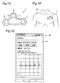
- FIG. 1A is a perspective view illustrating an embodiment of an electrocardiographic transmitter according to the present invention
- FIG. 1B is an explanatory diagram illustrating an example of a state in which the electrocardiographic transmitter is mounted on a chest of a subject
- FIG. 1C is an explanatory diagram showing an example of a state in which an electrocardiogram is displayed on a display of the terminal.
- 2A is a plan view
- FIG. 2B is a bottom view showing a state where an electrode pad is removed, showing an example of an external appearance of a main body of the electrocardiographic transmitter.
- FIG. 2 is a block diagram illustrating an example of an electrical configuration of an electrocardiographic transmitter. It is a lineblock diagram showing one embodiment of an electrocardiogram measurement system concerning the present invention.
- FIG. 9 is a graph illustrating an example of an electrocardiogram waveform
- FIG. 9B is a graph illustrating an example of a synchronization pulse of the electrocardiogram waveform.
- 11 is a flowchart illustrating still another example of the operation of the electrocardiographic transmitter and the terminal.
- 5 is a flowchart illustrating an example of the operation of the heart rate monitor and the terminal.
- FIG. 1A is a perspective view showing an embodiment of an electrocardiographic transmitter 1 according to the present invention.
- FIG. 1B is an explanatory diagram illustrating an example of a state in which the electrocardiographic transmitter 1 is mounted on the chest of the subject PA.
- FIG. 1C is an explanatory diagram illustrating an example of a state in which an electrocardiogram is displayed on the display 51 of the terminal 50.
- a power switch 11 is provided on the main body 10 of the electrocardiographic transmitter 1, and three electrode pads 2, 3, 4 can be mounted on the back side of the main body 10.
- Such an electrocardiographic transmitter 1 is mounted so that the electrode pads 2, 3, and 4 are electrically connected to the chest of the subject PA, so that an electrocardiographic signal can be measured.
- the external shape of the electrocardiographic transmitter 1 is not limited at all, as long as the electrocardiographic signal of the subject PA can be measured.
- the electrode pads 2, 3, and 4 cannot be attached to and detached from the main body 10. It may have a body shape, and the number of electrode pads may be two or three or more.
- the electrocardiographic transmitter 1 is, for example, Bluetooth (registered trademark) (Near Field Communication), NFC (Near Field Communication), personal area network (Personal Area Network: PAN), wireless LAN (Local Area Network), WiFi ( It is wirelessly connected to the terminal 50 via a wireless communication standard that assumes a relatively short distance such as Wireless Fidelity.
- Bluetooth registered trademark
- NFC Near Field Communication
- PAN Personal Area Network
- PAN Personal Area Network
- wireless LAN Local Area Network
- WiFi It is wirelessly connected to the terminal 50 via a wireless communication standard that assumes a relatively short distance such as Wireless Fidelity.
- the terminal 50 includes, for example, a smartphone, a handheld computer, a tablet PC, a desktop PC, and the like, and various software can be installed therein. Among them, by installing dedicated software specialized for the electrocardiographic measurement system according to the present invention, Receives an electrocardiographic signal wirelessly transmitted from the electrocardiographic transmitter 1, performs signal processing, and stores the electrocardiogram and various electrocardiographic parameters (for example, the respiratory rate RR and the heart rate HR) of the subject PA in a memory. Or display on the display 51 or transfer to an external host device (not shown).
- the terminal 50 wirelessly communicates with the host device via a wireless communication standard that assumes a relatively long distance, such as a wireless LAN (Local Area Network), WiFi (Wireless Fidelity), 3G, 4G (LTE), 5G, or the Internet. Connected.
- a wireless communication standard that assumes a relatively long distance, such as a wireless LAN (Local Area Network), WiFi (Wireless Fidelity), 3G, 4G (LTE), 5G, or the Internet. Connected.
- FIG. 2A and 2B show an example of the external appearance of the main body 10 of the electrocardiographic transmitter 1
- FIG. 2A is a plan view
- FIG. 2B is a bottom view showing a state in which electrode pads are removed.
- the main body 10 of the electrocardiographic transmitter 1 has a generally triangular shape with rounded corners, and a slide-type power switch 11 is provided on a side surface.
- terminals 12, 13, and 14 electrically connected to the electrode pads 2, 3, and 4 are provided on the bottom surface, and the electrode pads 2, 13, and 14 are provided near the terminals 12, 13, and 14, respectively.
- a pair of fasteners 12a, 13a, 14a mechanically connected to 3, 4 respectively are provided.
- a battery cover 15 for storing a battery (for example, a button-type battery) is provided at the center of the bottom surface.
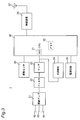
- FIG. 3 is a block diagram showing an example of an electrical configuration of the electrocardiographic transmitter 1.
- the electrocardiographic transmitter 1 includes a differential amplifier 21, a filter 22, an amplifier 23, and an R-wave detection circuit 24 connected to terminals 12, 13, and 14 as an electrocardiogram signal detection circuit. It includes a sensor 25, a CPU (central processing unit) 30 having a built-in A / D (analog-digital) converter 31 and a memory 32, a wireless communication circuit 26, an antenna 27, a power supply circuit 33, and the like.
- the differential amplifier 21 has a function of detecting an electrocardiographic signal by amplifying a difference between a potential generated at the electrode pad 2 and a potential generated at the electrode pad 4 using a potential generated at the electrode pad 3 located at the center as a ground potential. Have. Thereby, the in-phase component which is noise can be suppressed, and the negative-phase component which is signal can be amplified.
- the filter 22 includes a high-pass filter that suppresses low-frequency noise such as drift noise, a low-pass filter that suppresses high-frequency noise such as electromyogram signals, and a notch filter that suppresses specific frequency components such as commercial power supply noise. .
- the amplifier 23 has a function of amplifying the electrocardiographic signal and matching it with the input range of the A / D converter 31.
- the A / D converter 31 converts the electrocardiographic signal into a digital signal, and the digital signal is stored in the memory 32.
- the R-wave detection circuit 24 detects the position of the R-wave having the steepest peak in the electrocardiogram waveform (FIG. 9A), generates a synchronization pulse SYN (FIG. 9B) thereof, and provides it to the CPU 30. Based on the detected position of the R wave, the CPU 30 calculates various electrocardiographic parameters such as RR (millisecond: ms), which is the peak interval of the R wave, and heart rate HR (beats / minute: bpm) per unit time. Can be calculated. The CPU 30 can also wirelessly transmit the synchronization pulse SYN synchronized with the R wave to the terminal 50 via the wireless communication circuit 26.
- RR millisecond: ms
- HR heart rate
- the vibration sensor 25 includes a three-axis acceleration sensor, detects the respiration rate, the number of steps, the activity level, and the like of the subject PA, and provides the detected information to the CPU 30 via the A / D converter 31.
- the CPU 30 operates according to a preset program, and has a function of controlling signal processing such as an electrocardiographic signal and the operation of the entire apparatus.
- the wireless communication circuit 26 modulates a digital signal such as an electrocardiogram signal or a communication command of the CPU 30 into a high-frequency signal or converts a high-frequency signal received from the terminal 50 into a digital signal according to the above-described wireless communication standard such as Bluetooth (registered trademark). It has the function of demodulating.
- a digital signal such as an electrocardiogram signal or a communication command of the CPU 30 into a high-frequency signal or converts a high-frequency signal received from the terminal 50 into a digital signal according to the above-described wireless communication standard such as Bluetooth (registered trademark). It has the function of demodulating.
- the antenna 27 has a function of transmitting a high-frequency signal from the wireless communication circuit 26 and a function of receiving a high-frequency signal from the terminal 50.
- the power supply circuit 33 includes the power switch 11, a battery, and the like.
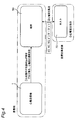
- FIG. 4 is a configuration diagram showing an embodiment of an electrocardiographic measurement system according to the present invention.
- the electrocardiographic measurement system includes the above-described electrocardiographic transmitter 1, a terminal 50 that wirelessly communicates with the electrocardiographic transmitter 1, and a host device 70 that wirelessly communicates with the terminal 50.
- the electrocardiographic transmitter 1 and the terminal 50 are installed near a patient, while the host device 70 is installed near a medical worker usually waiting at a location remote from the patient.
- the electrocardiographic transmitter 1 statistically processes an electrocardiographic signal and calculates an average value HRav of the heart rate HR within a predetermined time.
- the electrocardiographic transmitter 1 continuously transmits electrocardiogram data based on the electrocardiographic signal to the terminal 50.
- the terminal 50 receives the electrocardiogram data and transfers it to the host device 70 as it is.
- the host device 70 saves the transferred electrocardiogram data and provides it for diagnosis of a medical worker.
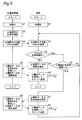
- FIG. 5 is a flowchart showing an example of the operation of the electrocardiographic transmitter 1 and the terminal 50.
- the terminal 50 determines whether the average value HRav is normal or abnormal.
- initialization is performed in step a1
- the interval for calculating the average value HRav of the heart rate HR is initially set. Is set.
- initialization is performed in step b1.
- the upper limit and lower limit of the normal range of the average value HRav of the heart rate HR, the threshold value of the non-transmission time of the electrocardiogram data, the electrocardiogram Initially, a data amount of a partial transmission of data is set.
- at least the upper and lower limits of the normal range of the average value HRav of the heart rate HR and the threshold value of the non-transmission time of the electrocardiogram data are arbitrary, for example, by the subject PA or a medical worker. May be set by In the case of Bluetooth (registered trademark), communication between the electrocardiographic transmitter 1 and the terminal 50 is established during initialization and data transmission (the same applies to other flowcharts).
- the electrocardiographic transmitter 1 starts measuring the electrocardiographic signal in step a2, calculates an average value HRav of the heart rate HR within a predetermined time (for example, one minute) in step a3, and sends the average value HRav to the terminal 50. Send.
- the terminal 50 receives the average value HRav of the heart rate HR transmitted from the electrocardiographic transmitter 1 in step b2, and then determines in step b3 whether the average value HRav is within a normal range (for example, 30 to 160 bpm). Is determined. If the average value HRav is within the normal range, the process returns to step b2 via step b6 (details will be described later). Thus, when the average value HRav is normal, the subject PA can be judged to be in a lucrative state, so that the power required for data transmission can be saved by not transmitting the electrocardiogram data having a huge data amount to the terminal 50.
- a normal range for example, 30 to 160 bpm
- step b3 if the average value HRav is out of the normal range in step b3, the subject PA can be determined to be in a serious condition, and the process proceeds to step b4, and the terminal 50 transmits the electrocardiogram data to the electrocardiogram transmission. Request to machine 1.
- the ECG transmitter 1 After receiving the ECG data request command in step a4, the ECG transmitter 1 continuously transmits the ECG data based on the ECG signal to the terminal 50.
- the terminal 50 receives the electrocardiogram data transmitted continuously in step b5, and transfers it to the host device 70 as it is. In this way, when the average value HRav is abnormal, it becomes possible to provide the medical staff with all the electrocardiogram data of the subject PA.
- step b6 will be described.
- the terminal 50 determines whether or not the non-transmission time of the electrocardiogram data has exceeded a predetermined time T1 (for example, one hour) in step b6. If the untransmitted time of the electrocardiogram data exceeds the time T1, the process proceeds to step b7, and the terminal 50 requests the electrocardiographic transmitter 1 to transmit a part (for example, 10 beats) of the electrocardiogram data. . After receiving the ECG data request command in step a5, the ECG transmitter 1 transmits only a part of the ECG data to the terminal 50.
- a predetermined time T1 for example, one hour
- the terminal 50 receives a part of the electrocardiogram data in step b8 and transfers it to the host device 70 as it is, and then returns to step b2. In this way, the medical worker can simply diagnose the electrocardiogram of the subject PA.
- the electrocardiographic transmitter 1 calculates the average value HRav of the heart rate HR.
- the biological signal information such as the number of R waves measured by the electrocardiographic transmitter 1 is transmitted to the terminal 50.
- software in the terminal 50 can calculate the average value HRav of the heart rate HR.
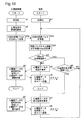
- FIG. 6 is a flowchart showing another example of the operation of the electrocardiographic transmitter 1 and the terminal 50.
- the electrocardiographic transmitter 1 determines whether the average value HRav is normal or abnormal will be described.
- initialization is performed in step c1, for example, the interval for calculating the average value HRav of the heart rate HR, the heart rate
- the upper limit and the lower limit of the normal range of the average value HRav of the HR are initially set.
- step c1 When the dedicated software installed in the terminal 50 is started, initialization is performed in step c1, and for example, a threshold value of the non-transmission time of the electrocardiogram data, a data amount of a partial transmission of the electrocardiogram data, and the like are initialized.
- a threshold value of the non-transmission time of the electrocardiogram data For example, a data amount of a partial transmission of the electrocardiogram data, and the like are initialized.
- the normal range of the average value HRav of the heart rate HR can also be initialized by inputting it at the terminal 50 and transmitting it to the electrocardiographic transmitter 1.
- the electrocardiographic transmitter 1 starts measuring an electrocardiographic signal in step c2, calculates an average value HRav of the heart rate HR within a predetermined time (for example, 1 minute) in step c3, Send.
- the terminal 50 receives the average value HRav of the heart rate HR transmitted from the electrocardiographic transmitter 1 in step d2.
- step c4 the electrocardiographic transmitter 1 determines whether or not the average value HRav is within a normal range (for example, 30 to 160 bpm). If the average value HRav is within the normal range, the process returns to step c3. Thus, when the average value HRav is normal, the subject PA can be judged to be in a lucrative state, so that the power required for data transmission can be saved by not transmitting the electrocardiogram data having a huge data amount to the terminal 50.
- a normal range for example, 30 to 160 bpm
- step c4 when the average value HRav is out of the normal range in step c4, the subject PA can be determined to be in a serious condition, and the process proceeds to step c5, where the electrocardiographic transmitter 1 determines the average heart rate HR.
- the terminal 50 is notified that the value HRav is abnormal.
- the terminal 50 requests the electrocardiogram transmitter 1 to transmit electrocardiogram data in step d4.
- the electrocardiogram transmitter 1 After receiving the request command for the electrocardiogram data in step c6, the electrocardiogram transmitter 1 continuously transmits electrocardiogram data based on the electrocardiogram signal to the terminal 50.
- the terminal 50 receives the electrocardiogram data continuously transmitted in step d5, and transfers it to the host device 70 as it is. In this way, when the average value HRav is abnormal, it becomes possible to provide the medical staff with all the electrocardiogram data of the subject PA.
- step d3 will be described.
- the terminal 50 determines in step d3 whether the untransmitted time of the electrocardiogram data has exceeded a predetermined time T1 (for example, one hour).
- a predetermined time T1 for example, one hour.
- the process proceeds to step d6, and the terminal 50 requests the electrocardiographic transmitter 1 to transmit a part (for example, 10 beats) of the electrocardiogram data.
- the electrocardiographic transmitter 1 After receiving the request command for the electrocardiogram data in step c7, the electrocardiographic transmitter 1 transmits only a part of the electrocardiogram data to the terminal 50.
- the terminal 50 receives a part of the electrocardiogram data in step d7 and transfers it to the host device 70 as it is, and then returns to step d2. In this way, the medical worker can simply diagnose the electrocardiogram of the subject PA.
- the electrocardiographic transmitter 1 calculates the average value HRav of the heart rate HR
- the biological signal information such as the number of R waves measured by the electrocardiographic transmitter 1 is transmitted to the terminal 50
- the average value HRav of the heart rate HR can be calculated by software in the terminal 50.
- FIG. 7 is a flowchart showing still another example of the operation of the electrocardiographic transmitter 1 and the terminal 50.
- step d2 is omitted from the flowchart of FIG. 6, and instead of step c3, the average value HRav of the heart rate HR within a predetermined time (for example, one minute) is calculated, but data transmission is omitted.
- Step c3a is performed.
- the electrocardiographic transmitter 1 determines the threshold value of the average value HRav in the next step c4, but does not transmit anything to the terminal 50 when the average value HRav is normal.
- partial transmission of the electrocardiogram data is performed (step c7). As a result, the frequency of data communication is reduced, thereby reducing power consumption and extending the life of the battery.
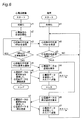
- FIG. 8 is a flowchart showing still another example of the operation of the electrocardiographic transmitter 1 and the terminal 50.
- the electrocardiographic transmitter 1 determines whether the average value HRav is normal or abnormal, and also determines the non-transmission time of the electrocardiogram data.
- initialization is performed in step c1, for example, the interval for calculating the average value HRav of the heart rate HR, the heart rate
- the upper limit and the lower limit of the normal range of the average value HRav of the HR are initially set.
- step c1 When the dedicated software installed in the terminal 50 is started, initialization is performed in step c1, and for example, a threshold value of the non-transmission time of the electrocardiogram data, a data amount of a partial transmission of the electrocardiogram data, and the like are initialized.
- a threshold value of the non-transmission time of the electrocardiogram data For example, a data amount of a partial transmission of the electrocardiogram data, and the like are initialized.
- the normal range of the average value HRav of the heart rate HR can also be initialized by inputting it at the terminal 50 and transmitting it to the electrocardiographic transmitter 1.
- the electrocardiographic transmitter 1 starts measuring the electrocardiographic signal in step c2, and calculates an average value HRav of the heart rate HR within a predetermined time (for example, one minute) in step c3a. Is not performed.
- step c4 the electrocardiographic transmitter 1 determines whether or not the average value HRav is within a normal range (for example, 30 to 160 bpm). If the average value HRav is within the normal range, the process returns to step c3a via step c4a (details will be described later). Thus, when the average value HRav is normal, the subject PA can be judged to be in a lucrative state, so that the power required for data transmission can be saved by not transmitting the electrocardiogram data having a huge data amount to the terminal 50.
- a normal range for example, 30 to 160 bpm
- step c4 the electrocardiographic transmitter 1 determines based on the electrocardiographic signal.
- the ECG data is continuously transmitted to the terminal 50.
- the terminal 50 receives the electrocardiogram data continuously transmitted in step d5, and transfers it to the host device 70 as it is. In this way, when the average value HRav is abnormal, it becomes possible to provide the medical staff with all the electrocardiogram data of the subject PA.
- step c4a will be described.
- the electrocardiographic transmitter 1 determines whether or not the untransmitted time of the electrocardiogram data has exceeded a predetermined time T1 (for example, one hour) in step c4a.
- a predetermined time T1 for example, one hour
- the process proceeds to step c7, and the electrocardiographic transmitter 1 transmits only a part (for example, 10 beats) of the electrocardiogram data to the terminal 50.
- the terminal 50 receives a part of the electrocardiogram data in step d7 and transfers it to the host device 70 as it is, and then returns after step d1. In this way, the medical worker can simply diagnose the electrocardiogram of the subject PA.
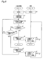
- FIG. 10 is a flowchart showing still another example of the operation of the electrocardiographic transmitter 1 and the terminal 50.
- the electrocardiographic transmitter 1 generates a synchronization pulse SYN of an electrocardiogram waveform and wirelessly transmits the synchronization pulse SYN
- the terminal 50 calculates an average value HRav from the synchronization pulse SYN, and determines whether it is normal or abnormal.
- initialization is performed in step a1, and, for example, an R-wave detection threshold is initialized.
- step b1 When the dedicated software installed in the terminal 50 is started, initialization is performed in step b1, for example, the interval for calculating the average value HRav of the heart rate HR, the upper limit of the normal range of the average value HRav of the heart rate HR, and The lower limit, the threshold value of the untransmitted time of the electrocardiogram data, the data amount of partial transmission of the electrocardiogram data, and the like are initialized.
- the upper and lower limits of the normal range of the average value HRav of the heart rate HR and the threshold value of the non-transmission time of the electrocardiogram data are arbitrary, for example, by the subject PA or a medical worker. May be set by
- the electrocardiographic transmitter 1 starts measuring an electrocardiographic signal in step a2, generates an R-wave synchronization pulse SYN in step a3a, and transmits it to the terminal 50.
- the terminal 50 receives the synchronization pulse SYN transmitted from the electrocardiographic transmitter 1 in step b2a, calculates an average value HRav of the heart rate HR from the synchronization pulse SYN in step b2b, and then calculates the average value HRav in step b3. It is determined whether the value HRav is within a normal range (for example, 30 to 160 bpm). If the average value HRav is within the normal range, the process returns to step b2 via step b6 (for details, see the description of steps b6 to b8 in FIG. 5). Thus, when the average value HRav is normal, the subject PA can be judged to be in a lucrative state, so that the power required for data transmission can be saved by not transmitting the electrocardiogram data having a huge data amount to the terminal 50.
- a normal range for example, 30 to 160 bpm
- step b3 if the average value HRav is out of the normal range in step b3, the subject PA can be determined to be in a serious condition, and the process proceeds to step b4, and the terminal 50 transmits the electrocardiogram data to the electrocardiogram transmission. Request to machine 1.
- the ECG transmitter 1 After receiving the ECG data request command in step a4, the ECG transmitter 1 continuously transmits the ECG data based on the ECG signal to the terminal 50.
- the terminal 50 receives the electrocardiogram data transmitted continuously in step b5, and transfers it to the host device 70 as it is. In this way, when the average value HRav is abnormal, it becomes possible to provide the medical staff with all the electrocardiogram data of the subject PA.
- the synchronization pulse SYN synchronized with the R wave is generated.
- the synchronization pulse SYN synchronized with the P wave, Q wave, S wave or T wave of the electrocardiogram waveform shown in FIG. 9A is generated. It is also possible.
- the heart rate meter has a function of measuring a heart rate by optically detecting a change in blood flow in a blood vessel instead of an electrocardiographic signal, and is attached to, for example, a chest, a wrist, an arm, or a neck.
- FIG. 11 is a flowchart illustrating an example of the operation of the heart rate monitor and the terminal. This flowchart omits steps c6, c7, d2 to d7 in the flowchart of FIG. 6, performs step c2a for starting heart rate measurement instead of step c2, and further performs predetermined time instead of step c3.
- the average value HRav of the heart rate HR within the period (for example, for one minute) is calculated, but step c3a in which data transmission is omitted is performed.
- the heart rate monitor determines the threshold value of the average value HRav in the next step c4. However, if the average value HRav is normal, it does not transmit anything to the terminal 50, and if the average value HRav is abnormal, Is notified to the terminal 50 (step c5), and the terminal 50 receives the abnormality notification of the average value HRav (step d10). This further reduces the frequency of data communication, thereby reducing power consumption and extending the life of the battery.
- the method of simply monitoring the state of the subject PA using the average value HRav of the heart rate HR as the statistic of the electrocardiographic signal has been exemplified.
- At least one parameter selected from the group consisting of the average value, the minimum value, the maximum value, the median value, the mode value, the variance, and the standard deviation of the heart rate within may be used.
- the average value is a value obtained by dividing the total value of data by the number of data.
- the minimum value is the smallest value in the data.
- the maximum value is the largest value in the data.
- the median value is a value located at the center when the data is arranged in ascending order. When the data is an even number, the average of two values near the center is calculated.
- the mode is the value of the data with the highest frequency.
- the variance is the mean of the squares of the difference between the mean and the individual data. Standard deviation is the positive square root of the variance.
- the present invention is extremely useful industrially in that the heart condition of a subject can be monitored over a long period of time.
Landscapes
- Health & Medical Sciences (AREA)
- Life Sciences & Earth Sciences (AREA)
- Engineering & Computer Science (AREA)
- Cardiology (AREA)
- Medical Informatics (AREA)
- Molecular Biology (AREA)
- Biophysics (AREA)
- Pathology (AREA)
- Biomedical Technology (AREA)
- Heart & Thoracic Surgery (AREA)
- Veterinary Medicine (AREA)
- Physics & Mathematics (AREA)
- Surgery (AREA)
- Animal Behavior & Ethology (AREA)
- General Health & Medical Sciences (AREA)
- Public Health (AREA)
- Physiology (AREA)
- Computer Networks & Wireless Communication (AREA)
- Signal Processing (AREA)
- Measurement And Recording Of Electrical Phenomena And Electrical Characteristics Of The Living Body (AREA)
Abstract
Dans la présente invention : 1) un émetteur ECG (1) traite statistiquement des signaux ECG et calcule une valeur moyenne (FCmoy) de la fréquence cardiaque (FC) au sein d'un laps de temps prédéfini, et si la valeur moyenne (FCmoy) de la fréquence cardiaque FC est anormale, l'émetteur ECG (1) envoie en continu, à un terminal (50), des données ECG basées sur les signaux ECG; 2) le terminal (50) reçoit les données ECG et transfère les données à un dispositif hôte (70); et 3) le dispositif hôte (70) stocke les données ECG transférées, et fournit les données à des fins de diagnostic par le personnel médical. Ainsi, l'état du cœur d'un sujet peut être surveillé sur une longue période.
Priority Applications (5)
| Application Number | Priority Date | Filing Date | Title |
|---|---|---|---|
| US17/258,031 US20210228077A1 (en) | 2018-07-06 | 2019-06-18 | Ecg measurement system and ecg transmitter |
| EP19830641.7A EP3818931A4 (fr) | 2018-07-06 | 2019-06-18 | Système de mesure ecg et émetteur ecg |
| CN201980045037.7A CN112384142A (zh) | 2018-07-06 | 2019-06-18 | 心电测量系统及心电发射器 |
| JP2020528772A JP7216092B2 (ja) | 2018-07-06 | 2019-06-18 | 心電計測システムおよび心電送信機 |
| US18/350,809 US20230346219A1 (en) | 2018-07-06 | 2023-07-12 | Ecg measurement system and ecg transmitter |
Applications Claiming Priority (2)
| Application Number | Priority Date | Filing Date | Title |
|---|---|---|---|
| JP2018129081 | 2018-07-06 | ||
| JP2018-129081 | 2018-07-06 |
Related Child Applications (2)
| Application Number | Title | Priority Date | Filing Date |
|---|---|---|---|
| US17/258,031 A-371-Of-International US20210228077A1 (en) | 2018-07-06 | 2019-06-18 | Ecg measurement system and ecg transmitter |
| US18/350,809 Division US20230346219A1 (en) | 2018-07-06 | 2023-07-12 | Ecg measurement system and ecg transmitter |
Publications (1)
| Publication Number | Publication Date |
|---|---|
| WO2020008864A1 true WO2020008864A1 (fr) | 2020-01-09 |
Family
ID=69060209
Family Applications (1)
| Application Number | Title | Priority Date | Filing Date |
|---|---|---|---|
| PCT/JP2019/024104 WO2020008864A1 (fr) | 2018-07-06 | 2019-06-18 | Système de mesure ecg et émetteur ecg |
Country Status (5)
| Country | Link |
|---|---|
| US (2) | US20210228077A1 (fr) |
| EP (1) | EP3818931A4 (fr) |
| JP (1) | JP7216092B2 (fr) |
| CN (1) | CN112384142A (fr) |
| WO (1) | WO2020008864A1 (fr) |
Families Citing this family (4)
| Publication number | Priority date | Publication date | Assignee | Title |
|---|---|---|---|---|
| JP1663031S (fr) * | 2019-11-20 | 2020-07-06 | ||
| TWD209299S (zh) * | 2020-03-03 | 2021-01-11 | 廣達電腦股份有限公司 | 具心肺音量測聽診功能之無線隨身心電圖量測器 |
| TWD207562S (zh) * | 2020-03-09 | 2020-10-01 | 廣達電腦股份有限公司 | 心電圖紀錄器與充電座組 |
| TWD209225S (zh) * | 2020-05-06 | 2021-01-01 | 廣達電腦股份有限公司 | 心電圖紀錄器與充電座組 |
Citations (4)
| Publication number | Priority date | Publication date | Assignee | Title |
|---|---|---|---|---|
| JP2006136405A (ja) * | 2004-11-10 | 2006-06-01 | Harada Denshi Kogyo Kk | 装着型無線伝送式心電計 |
| WO2016024495A1 (fr) * | 2014-08-11 | 2016-02-18 | 日本電信電話株式会社 | Système de mesure de signal biologique, dispositif de mesure d'informations biologiques et procédé de modification d'algorithme d'extraction d'informations biologiques |
| JP2017209482A (ja) | 2016-03-15 | 2017-11-30 | 日本光電工業株式会社 | 検出装置及び当該検出装置を備えるアラームシステム |
| JP2018019840A (ja) | 2016-08-02 | 2018-02-08 | 株式会社フジキン | 心電図監視システム及びこのシステムで使用する携帯型心電計 |
Family Cites Families (3)
| Publication number | Priority date | Publication date | Assignee | Title |
|---|---|---|---|---|
| US20150313502A1 (en) * | 2014-05-02 | 2015-11-05 | Xerox Corporation | Determining arterial pulse wave transit time from vpg and ecg/ekg signals |
| CN104921710A (zh) * | 2015-06-18 | 2015-09-23 | 深圳市润安科技发展有限公司 | 学生静态生理参数远程监控系统及其远程监控方法 |
| CN105125207A (zh) * | 2015-09-22 | 2015-12-09 | 吉林大学 | 一种移动式心电监测终端 |
-
2019
- 2019-06-18 CN CN201980045037.7A patent/CN112384142A/zh active Pending
- 2019-06-18 EP EP19830641.7A patent/EP3818931A4/fr active Pending
- 2019-06-18 US US17/258,031 patent/US20210228077A1/en not_active Abandoned
- 2019-06-18 JP JP2020528772A patent/JP7216092B2/ja active Active
- 2019-06-18 WO PCT/JP2019/024104 patent/WO2020008864A1/fr unknown
-
2023
- 2023-07-12 US US18/350,809 patent/US20230346219A1/en active Pending
Patent Citations (4)
| Publication number | Priority date | Publication date | Assignee | Title |
|---|---|---|---|---|
| JP2006136405A (ja) * | 2004-11-10 | 2006-06-01 | Harada Denshi Kogyo Kk | 装着型無線伝送式心電計 |
| WO2016024495A1 (fr) * | 2014-08-11 | 2016-02-18 | 日本電信電話株式会社 | Système de mesure de signal biologique, dispositif de mesure d'informations biologiques et procédé de modification d'algorithme d'extraction d'informations biologiques |
| JP2017209482A (ja) | 2016-03-15 | 2017-11-30 | 日本光電工業株式会社 | 検出装置及び当該検出装置を備えるアラームシステム |
| JP2018019840A (ja) | 2016-08-02 | 2018-02-08 | 株式会社フジキン | 心電図監視システム及びこのシステムで使用する携帯型心電計 |
Also Published As
| Publication number | Publication date |
|---|---|
| EP3818931A4 (fr) | 2022-07-27 |
| CN112384142A (zh) | 2021-02-19 |
| US20230346219A1 (en) | 2023-11-02 |
| EP3818931A1 (fr) | 2021-05-12 |
| US20210228077A1 (en) | 2021-07-29 |
| JP7216092B2 (ja) | 2023-01-31 |
| JPWO2020008864A1 (ja) | 2021-07-08 |
Similar Documents
| Publication | Publication Date | Title |
|---|---|---|
| WO2020008864A1 (fr) | Système de mesure ecg et émetteur ecg | |
| US20220015647A1 (en) | Apparatus and system for monitoring | |
| US9179864B2 (en) | Wearable health monitoring device and methods for fall detection | |
| US20050080322A1 (en) | Monitoring method and monitoring system for assessing physiological parameters of a subject | |
| JP2007520273A (ja) | 適合型生理学的モニタリングシステム及びこのシステムを使用する方法 | |
| JP2007520273A5 (fr) | ||
| WO2012015818A2 (fr) | Système et procédé pour réduire les fausses alarmes et les faux négatifs | |
| WO2023142707A1 (fr) | Appareil de détection de caractéristique physiologique, système de détection de caractéristique physiologique et système de soins | |
| US20040243005A1 (en) | Remote speaker microphone having vital sign monitoring capability | |
| TW202133193A (zh) | 生理訊號量測裝置動態閾值調校系統 | |
| US20210121133A1 (en) | System and method for risk detection and intervention to prevent sudden death | |
| KR20130082878A (ko) | 생체 신호 송신 장치, 이를 이용하는 생체 신호 모니터링 시스템 및 그 방법 | |
| CN113303804A (zh) | 生理讯号测量装置动态阈值调校系统 | |
| AU2018206855A1 (en) | Apparatus and system for monitoring | |
| CN111329471B (zh) | 一种心内科便携式监护装置 | |
| JP7208843B2 (ja) | 医用テレメータシステム | |
| JP7222616B2 (ja) | センサ、および生体情報監視システム | |
| Agarwal | An Embedded system for determining arrhythmia | |
| CN114129174A (zh) | 一种可穿戴式心电监测装置 | |
| AU2022291482A1 (en) | Apparatus and system for monitoring | |
| CN116847778A (zh) | 用于测量多个生物信号的可穿戴设备以及使用该设备的基于人工智能的远程监测系统 |
Legal Events
| Date | Code | Title | Description |
|---|---|---|---|
| 121 | Ep: the epo has been informed by wipo that ep was designated in this application |
Ref document number: 19830641 Country of ref document: EP Kind code of ref document: A1 |
|
| ENP | Entry into the national phase |
Ref document number: 2020528772 Country of ref document: JP Kind code of ref document: A |
|
| NENP | Non-entry into the national phase |
Ref country code: DE |