WO2020008852A1 - Roof rail device, support bracket, and roof rail mounting structure - Google Patents
Roof rail device, support bracket, and roof rail mounting structure Download PDFInfo
- Publication number
- WO2020008852A1 WO2020008852A1 PCT/JP2019/023967 JP2019023967W WO2020008852A1 WO 2020008852 A1 WO2020008852 A1 WO 2020008852A1 JP 2019023967 W JP2019023967 W JP 2019023967W WO 2020008852 A1 WO2020008852 A1 WO 2020008852A1
- Authority
- WO
- WIPO (PCT)
- Prior art keywords
- bracket
- roof
- support
- support bracket
- rail
- Prior art date
Links
Images


Classifications
-
- B—PERFORMING OPERATIONS; TRANSPORTING
- B60—VEHICLES IN GENERAL
- B60R—VEHICLES, VEHICLE FITTINGS, OR VEHICLE PARTS, NOT OTHERWISE PROVIDED FOR
- B60R9/00—Supplementary fittings on vehicle exterior for carrying loads, e.g. luggage, sports gear or the like
- B60R9/04—Carriers associated with vehicle roof
- B60R9/058—Carriers associated with vehicle roof characterised by releasable attaching means between carrier and roof
Definitions
- the present disclosure relates to a roof rail device, a support bracket, and a roof rail mounting structure.
- Patent Document 1 describes a roof rail.
- the roof rail is disposed on the roof and extends in the front-rear direction of the vehicle, a roof rail body, an end supporting leg for supporting an end of the roof rail body to the vehicle roof, and an intermediate portion of the roof rail body for the roof.
- the intermediate support leg has an intermediate support leg main body that supports a load acting on the roof rail main body.
- the intermediate support leg main body is made of metal having a roof mounting surface portion mounted on the roof via an intermediate cushion material and a rail mounting surface portion mounted on the bottom surface of the roof rail main body, and is formed by, for example, aluminum die casting.
- the roof mounting surface is provided with two through holes for inserting fastening members such as bolts, and is fixed to the roof by the fastening members inserted into the through holes.
- the rail mounting surface is provided with a through hole for inserting a fastening member such as a bolt, and a positioning projection formed to project upward and inserted into a positioning hole provided on the bottom surface of the roof rail body. I have. Then, the rail mounting surface portion is fixed to the bottom surface of the roof rail main body by a fastening member inserted through the through hole in a state where the positioning projection is inserted into the positioning hole and positioned.
- the intermediate support leg body (support bracket) is pre-assembled in a state of being positioned with respect to the roof rail body (roof rail). Assembled.
- the end support legs at the front and rear ends of the roof rail are fixed to the roof panel of the vehicle.
- the position of the through hole (mounting part) of the support bracket and the position of the through hole (mounting part) of the roof panel are shifted due to manufacturing errors of the support bracket and the support bracket, making it difficult to attach the roof rail to the roof panel. May be lost.
- the present disclosure can easily adjust the position of the mounting portion of the support bracket and the predetermined mounting position of the roof panel even in a state where the roof rail and the support bracket are pre-assembled and subassembled, and the roof rail can be mounted on the roof rail. It is an object of the present invention to provide a roof rail device, a support bracket, and a roof rail mounting structure that can be mounted on a panel.
- a first aspect of the present invention is a roof rail device attached to a roof panel of a vehicle, including a roof rail and a support bracket.
- the roof rail has a rail-side assembly portion and extends in the front-rear direction above the roof panel.
- the support bracket includes a bracket-side mounting portion that is movably mounted within a predetermined range in a direction intersecting the vertical direction with respect to the rail-side mounting portion of the roof rail, and a mounting portion that can be mounted on the roof panel. And is attached to the roof panel in a state where it is assembled in advance to the roof rail.
- the bracket-side assembly portion of the support bracket is movably attached to the rail-side assembly portion of the roof rail within a predetermined range in a direction crossing the vertical direction. For this reason, when installing the roof rail device, which is a sub-assembly in which the roof rail and the support bracket are pre-assembled and assembled, to the roof panel, the position of the mounting portion of the support bracket and the predetermined position Even when the mounting position is shifted in a direction crossing the vertical direction, manufacturing errors and the like of the roof rail and the support bracket can be absorbed within the above-described predetermined range.
- the roof rail can be easily attached to the roof panel, and the roof rail can be attached to the roof panel.
- a second aspect of the present invention is the roof rail device according to the first aspect, wherein one of the rail-side assembly part of the roof rail or the bracket-side assembly part of the support bracket intersects the vertical direction. And the other mounting part of the rail-side mounting part of the roof rail or the bracket-side mounting part of the support bracket is a supported part of the one mounting part in a vertically separated state. And upper and lower support portions for partitioning a space in which can be arranged. The supported portion of the one mounting portion is disposed in the space of the other mounting portion, and is vertically movable in the predetermined range in a direction intersecting the vertical direction. Supported by
- the support portion extending in the direction intersecting the vertical direction of one of the mounting portions is supported by the upper and lower support portions of the other mounting portion.
- a roof rail having a plate portion intersecting with the vertical direction and a bracket insertion hole penetrating the plate portion in the vertical direction is previously assembled, and the roof rail is attached to a roof panel of a vehicle.
- the first support bracket has an insertion portion through which the bracket insertion hole of the roof rail is inserted, and a first support bracket protruding from an upper end portion of the insertion portion toward the outside in the radial direction of the bracket insertion hole, is disposed above the plate portion of the roof rail, and And an upper supporting portion that comes into contact with or comes into contact with.
- the second support bracket is disposed below the plate-shaped portion of the roof rail, has a lower support portion that is close to or in contact with the plate-shaped portion, is disposed below the plate-shaped portion, and has a bracket insertion hole of the roof rail. It is fixed to the insertion portion of the first support bracket in the inserted state.
- the first support bracket or the second support bracket has a mounting portion that can be mounted on the roof panel. The upper support portion of the first support bracket and the lower support portion of the second support bracket support the plate-like portion of the roof rail movably within a predetermined range in a direction crossing the vertical direction.
- the insertion portion of the first support bracket is inserted into the bracket insertion hole of the roof rail from above, and the second support bracket is fixed to the insertion portion of the first support bracket projecting downward from the bracket insertion hole.
- the support bracket can be assembled to the roof rail.
- the upper support portion of the first support bracket and the lower support portion of the second support bracket movably support the plate-like portion of the roof rail within a predetermined range in a direction crossing the vertical direction. That is, the support bracket is mounted movably within a predetermined range in a direction crossing the vertical direction with respect to the roof rail. Therefore, when the roof rail and the support bracket are mounted on the roof panel in a sub-assembly state, the position of the mounting portion of the support bracket and the predetermined mounting position of the roof panel may be reduced due to a manufacturing error of the roof rail or the support bracket.
- a fourth aspect of the present invention is the support bracket according to the third aspect, wherein the first support bracket and the second support bracket are fixed and the first support bracket and the second support bracket are fixed. Is provided with a gap extending in the up-down direction and having both upper and lower sides open.
- a fifth aspect of the present invention is a roof rail mounting structure, which includes a roof panel, a roof rail, and a support bracket.
- the roof panel has a roof-side through hole that penetrates in the up-down direction and allows the fixing member to pass therethrough.
- the roof rail has a plate-shaped portion crossing the vertical direction and a bracket insertion hole penetrating the plate-shaped portion in the vertical direction, and extends in the front-rear direction above the roof panel.
- the support bracket has a first support bracket and a second support bracket fixed to the first support bracket, and is attached to the roof panel in a state where the support bracket is previously attached to the roof rail.
- the first support bracket has an insertion portion through which the bracket insertion hole of the roof rail is inserted, and a first support bracket protruding from an upper end portion of the insertion portion toward the outside in the radial direction of the bracket insertion hole, is disposed above the plate portion of the roof rail, and And an upper supporting portion that comes into contact with or comes into contact with.
- the second support bracket is disposed below the plate-shaped portion of the roof rail, has a lower support portion that is close to or in contact with the plate-shaped portion, is disposed below the plate-shaped portion, and has a bracket insertion hole of the roof rail. It is fixed to the insertion portion of the first support bracket in the inserted state.
- the upper support portion of the first support bracket and the lower support portion of the second support bracket support the plate-like portion of the roof rail movably within a predetermined range in a direction crossing the vertical direction.
- the first support bracket or the second support bracket includes a mounting portion disposed above the roof side through hole of the roof panel, and a bracket side through hole that vertically passes through the mounting portion and allows the fixing member to pass therethrough.
- the mounting portion of the support bracket is fixed to the roof panel by a fixing member inserted through the roof side through hole and the bracket side through hole.
- the area around the bracket-side through-hole on the lower surface of the support bracket mounting part is the area around the roof-side through-hole on the upper surface of the roof panel with the support bracket mounting part fixed to the roof panel. Surface contact.
- the upper support portion of the first support bracket and the lower support portion of the second support bracket movably support the plate-like portion of the roof rail within a predetermined range in a direction crossing the vertical direction.
- the support bracket is mounted movably within a predetermined range in a direction crossing the vertical direction with respect to the roof rail. Therefore, when the roof rail and the support bracket are mounted on the roof panel in a sub-assembly state, manufacturing errors and the like of the roof rail and the support bracket can be absorbed within the above-described predetermined range.
- the roof rail can be attached to the roof panel by easily adjusting the position of the part and the predetermined attachment position of the roof panel.
- the area around the bracket-side through hole on the lower surface of the support bracket mounting portion is the area around the roof-side through hole on the upper surface of the roof panel with the mounting portion of the support bracket fixed to the roof panel. , The sealability between the lower surface of the support bracket and the upper surface of the roof panel can be secured, and water can be suppressed from entering the roof side through hole of the roof panel.
- the support bracket is mounted so as to be movable within a predetermined range in a direction crossing the vertical direction with respect to the roof rail, the diameter of the bracket side through hole of the support bracket and the roof side through hole of the roof panel must be increased.
- the position of the through hole of the support bracket and the position of the roof side through hole of the roof panel can be matched.
- the diameter of the bracket-side through-hole of the support bracket or the roof-side through-hole of the roof panel does not need to be increased, the contact area between the lower surface of the support bracket and the upper surface of the roof panel is ensured accordingly. Therefore, the sealing property between the lower surface of the support bracket and the upper surface of the roof panel can be ensured.
- a sixth aspect of the present invention is the roof rail mounting structure according to the fifth aspect, further comprising a seal member.
- the seal member is disposed between an outer peripheral area surrounding the entire outer peripheral area of the lower surface of the mounting portion of the support bracket and in contact with the upper surface of the roof panel, and an upper surface of the roof panel. Seal between the roof panel and the upper surface.
- the seal member surrounds the entire outer periphery of a region (hereinafter, referred to as a contact region) of the lower surface of the mounting portion of the support bracket, which is in surface contact with the upper surface of the roof panel, and the roof panel.
- a seal is provided between the outer peripheral area and the upper surface of the roof panel.
- the position of the mounting portion of the support bracket and the predetermined mounting position of the roof panel can be easily adjusted, and the roof rail can be mounted on the roof. Can be attached to the panel.
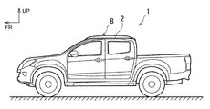
- FIG. 1 is a side view of a vehicle to which a roof rail is attached.
- FIG. 2 is a schematic explanatory view of the roof rail.
- FIG. 3 is an exploded perspective view of the intermediate bracket according to one embodiment of the present invention.
- FIG. 4 is a cross-sectional view showing a state where the roof rail is attached to a vehicle.
- FIG. 5 is a plan view showing a state where the roof rail is attached to the vehicle.
- FIG. 6 is a perspective view of the intermediate bracket from the inside in the vehicle width direction.
- FIG. 7 is a perspective view of the intermediate bracket from the outside in the vehicle width direction.
- FIG. 8 is a cross-sectional view corresponding to FIG. 4 when the mounting portion is provided on the second bracket.
- FIG. 4 is a side view of a vehicle to which a roof rail is attached.
- FIG. 2 is a schematic explanatory view of the roof rail.
- FIG. 3 is an exploded perspective view of the intermediate bracket according to one embodiment of the present
- FIG. 9 is a cross-sectional view corresponding to FIG. 4 in a case where a supported portion is provided on the intermediate bracket side and upper and lower support portions are provided on the roof rail side.
- FIG. 10 is a cross-sectional view corresponding to FIG. 4 in a case where a supported portion is provided on the intermediate bracket side and upper and lower support portions are provided on the roof rail side.
- FR indicates the front of the vehicle
- UP indicates the upper side
- IN indicates the inner side in the vehicle width direction.
- the front-rear direction means the front-rear direction of the vehicle
- the left-right direction means the left-right direction in a state where the vehicle faces the front.
- the roof rail device 8 As shown in FIG. 1, the roof rail device 8 according to the present embodiment is provided at a pair of left and right sides at both ends in the vehicle width direction of the roof panel 2 of the vehicle 1, and extends in a front-rear direction above the roof panel 2. It is attached to the roof panel 2.
- FIG. 1 shows only the left roof rail device 8. Further, since the roof rail device 8 is provided symmetrically on the left and right sides of the roof panel 2 and has substantially the same configuration, the left side will be described below and the right side description will be omitted.
- the roof rail device 8 includes a roof rail 10 extending in the front-rear direction above the roof panel 2, and a plurality of brackets 9 for attaching the roof rail 10 to the roof panel 2.
- the plurality of brackets 9 are attached to a pair of front and rear end brackets 5 attached to both front and rear ends of the roof rail 10, and the plurality of brackets 9 are attached to front and rear intermediate portions of the roof rail 10 in a state of being separated from each other (in the present embodiment, 2. ) Intermediate brackets (support brackets) 11.
- a roof rail 10 and a plurality of brackets 9 are sub-assembled.
- the roof rail mounting structure according to the present disclosure is applied to a mounting structure for mounting an intermediate portion of the roof rail 10 to the roof panel 2. Since the plurality of intermediate brackets 11 have substantially the same configuration, only one intermediate bracket 11 will be described below, and description of the other intermediate bracket 11 will be omitted.
- a groove 3 is formed at the outer end of the roof panel 2 in the vehicle width direction and extends in the front-rear direction while being recessed downward.
- a bolt insertion hole (roof-side through-hole) 4 is formed in the bottom plate 27 of the groove 3 of the roof panel 2 so as to penetrate in the vertical direction.
- the nut 6 is fixed to the lower surface of the bottom plate 27 at a position corresponding to the bolt insertion hole 4.
- the area around the bolt insertion hole 4 of the bottom plate 27 of the groove 3 of the roof panel 2 and the nut 6 function as a mounting portion 7 (a predetermined mounting position) for mounting the roof rail device 8.
- the roof rail 10 is arranged in the groove 3 of the roof panel 2 and is attached to the roof panel 2 via the intermediate bracket 11.
- the roof rail device 8 may be attached to the flat roof panel 2 without providing the groove 3 at the outer end of the roof panel 2 in the vehicle width direction.
- the roof rail 10 is formed in a substantially cylindrical shape extending in the front-rear direction.
- the upper rail portion 12 that partitions the upper part of the roof rail 10 and the lower rail plate portion (plate portion, supported portion, rail-side assembly portion) 13 that partitions the lower portion are vertically separated from each other.
- a generally rectangular bracket insertion hole 14 is formed in the rail upper plate portion 12 and penetrated in the up-down direction, and a bracket insertion hole of the rail lower plate portion 13 is formed in the rail lower plate portion 13 and penetrates in the vertical direction.
- a generally rectangular bracket insertion hole (rail-side assembly portion) 15 smaller than 14 is formed.
- the bracket insertion hole 14 of the rail upper plate portion 12 is formed to have a size that allows a first bracket 16 described later of the intermediate bracket 11 to be inserted into the roof rail 10 from above.
- the bracket insertion hole 14 of the rail upper plate portion 12 and the bracket insertion hole 15 of the rail lower plate portion 13 are arranged at positions vertically communicating with each other.
- the intermediate bracket 11 is composed of two brackets, a first bracket (first support bracket) 16 and a second bracket (second support bracket) 17.
- the first bracket 16 includes a lower plate portion (attachment portion) 18 that crosses the vertical direction, a first front plate portion (insertion portion) 19 that stands upright from the front edge of the lower plate portion 18 in the vehicle width direction, A front support plate portion (upper support portion, bracket-side assembling portion) 20 protruding forward from an upper end portion of the first front plate portion 19, and an upright standing along the vehicle width direction from a rear edge of the lower plate portion 18.
- a first rear plate portion (insertion portion) 21, a rear support plate portion (upper support portion, bracket-side assembly portion) 22 projecting rearward from an upper end of the first rear plate portion 21, and a lower plate portion 18.
- a thick-walled cylindrical portion (attaching portion) 23 projecting upward from the upper surface of the solid-state imaging device.
- the first bracket 16 is made of, for example, aluminum die-cast.
- the lower plate portion 18 of the first bracket 16 is formed in a substantially rectangular shape in a top view, having a size smaller than the bracket insertion hole 15 of the rail lower plate portion 13 of the roof rail 10.
- a bolt insertion hole (bracket-side through hole) 24 extending in the vertical direction is formed at a substantially central portion of the lower plate portion 18 of the first bracket 16.
- the bolt insertion hole 24 extends from the lower surface 25 of the lower plate portion 18 to the upper surface of a tubular portion 23 described later, and penetrates the lower plate portion 18 and the tubular portion 23 in the vertical direction.
- a protruding portion 26 protruding downward and having a rectangular shape as viewed from below is formed.
- the lower end of the bolt insertion hole 24 opens at a substantially central portion of the lower surface 25a of the protrusion 26.
- the lower surface 25a of the protruding portion 26 of the lower surface 25 of the lower plate portion 18 (the area around the bracket side through hole) is outside the protruding portion 26 of the lower surface 25 of the lower plate portion 18 (in the radial direction of the bolt insertion hole 24). (Outside), and is located below the outer peripheral region 25b surrounding the projecting portion 26 over the entire peripheral region.
- the first front plate portion 19 and the first rear plate portion 21 of the first bracket 16 are formed in a plate shape crossing the front-rear direction, and are provided symmetrically around the first bracket 16 and have substantially the same configuration.
- the first front plate portion 19 and the first rear plate portion 21 extend in a direction away from each other in a forward and backward direction from below to above and face each other. That is, the first front plate portion 19 and the first rear plate portion 21 are inclined with respect to the vertical direction.
- the first front plate portion 19 and the first rear plate portion 21 have a lower region 44 formed in an inverted trapezoidal shape that tapers downward from above in a front view (or a rear view), and an upper end of the lower region 44.
- the distance L1 in the front-rear direction between the front surface of the upper end portion of the upper region 45 of the first front plate portion 19 and the rear surface of the upper end portion of the upper region 45 of the first rear plate portion 21 is equal to the distance L1 of the bracket insertion hole 15 of the roof rail 10. It is less than the length (size) L2 in the front-rear direction.
- the length L3 in the vehicle width direction of the upper end of the lower region 44 of the first front plate portion 19 and the upper end of the lower region 44 of the first rear plate portion 21 is in the vehicle width direction of the bracket insertion hole 15 of the roof rail 10. Is less than the length (size) L4.
- the length L5 in the vehicle width direction of the upper end of the upper region 45 of the first front plate portion 19 and the upper end of the upper region 45 of the first rear plate portion 21 is the length of the upper end of the lower region 44 in the vehicle width direction.
- the length (size) L4 of the bracket insertion hole 15 of the roof rail 10 in the vehicle width direction is shorter than the length L3.
- a bottomed cylindrical first pin press-in hole 28 extending rearward from the front surface of the first front plate 19 is formed.
- the front support plate portion 20 and the rear support plate portion 22 of the first bracket 16 are formed in a plate shape crossing the vertical direction, and are provided symmetrically around the first bracket 16 and have substantially the same configuration.
- the length of the front support plate portion 20 and the rear support plate portion 22 in the vehicle width direction is the vehicle width of the upper end of the upper region 45 of the first front plate portion 19 and the upper end of the upper region 45 of the first rear plate portion 21.
- the length is substantially the same as the length L5 in the direction.
- the distance L6 between the front edge of the front support plate 20 and the rear edge of the rear support plate 22 in the front-rear direction is longer than the length (size) L2 of the bracket insertion hole 15 of the roof rail 10 in the front-rear direction. .
- the front support plate 20 and the rear support plate 22 are separated from the rail lower plate 13 of the roof rail 10.
- the front edge 13a defining the front of the bracket insertion hole 15 or the rear edge 13b defining the rear of the bracket insertion hole 15 in the rail lower plate portion 13 from above.
- the tubular portion 23 of the first bracket 16 is formed in a tubular shape extending in the up-down direction, and is disposed between the first front plate portion 19 and the first rear plate portion 21 to move upward from the upper surface of the lower plate portion 18. It protrudes and defines a bolt insertion hole 24 in the inner diameter part.
- the front end surface and the rear end surface of the cylindrical portion 23 are connected to the rear surface of the first front plate portion 19 or the front surface of the first rear plate portion 21 by a plate-shaped connecting portion 46 extending in the vertical direction.
- a thin plate-shaped sealing member 29 is attached to the upper surface of the cylindrical portion 23.
- the second bracket 17 is an aluminum die-cast, formed in a substantially rectangular cylindrical shape extending in the up-down direction, and defines an inner space 36 that allows the insertion of the first bracket 16 in an inner diameter portion.
- the second bracket 17 intersects the second front plate portion (lower support portion, bracket-side assembly portion) 30 intersecting the front-rear direction with the front-rear direction at a position separated rearward from the second front plate portion 30.
- the second rear plate portion (lower support portion, bracket-side assembly portion) 31 is connected to the vehicle width direction inner ends of the second front plate portion 30 and the second rear plate portion 31 across the vehicle width direction.
- an outer plate 33 intersecting the vehicle width direction and connecting outer ends of the second front plate 30 and the second rear plate 31 in the vehicle width direction.
- the inner space 36 of the second bracket 17 allows the first bracket 16 to be inserted from above.
- the second front plate portion 30 and the second rear plate portion 31 of the second bracket 17 are provided symmetrically around the second bracket 17 and have substantially the same configuration.
- the second front plate portion 30 and the second rear plate portion 31 extend in a direction in which they are separated from each other back and forth from below to above and face each other. That is, the second front plate portion 30 and the second rear plate portion 31 are inclined with respect to the vertical direction.
- the second front plate portion 30 and the second rear plate portion 31 are formed in an inverted trapezoidal shape that tapers downward from above in a front view (or a rear view).
- the distance L7 in the front-rear direction between the front surface of the upper end portion of the second front plate portion 30 and the rear surface of the upper end portion of the second rear plate portion 31 is the length (size) of the bracket insertion hole 15 of the roof rail 10 in the front-rear direction. ) Longer than L2.
- a second pin press-in hole 34 extending rearward from the front surface of the second front plate 30 and penetrating the second front plate 30 is formed.
- the second pin press-in hole 34 is formed at a position communicating with the first pin press-in hole 28 of the first front plate 19 of the first bracket 16 in a state where the first bracket 16 is inserted into the inner space 36 of the second bracket 17. Is done.
- the second bracket 17 and the first bracket 16 are connected to the second pin press-in hole 34 and the first bracket 16 from the front of the second front plate 30 in a state where the first bracket 16 is inserted into the inner space 36 of the second bracket 17.
- a protruding portion 42 that extends in the vehicle width direction while protruding downward is provided.
- the inner plate portion 32 of the second bracket 17 connects the upper ends of the second front plate portion 30 and the second rear plate portion 31 to each other.
- the upper surface of the inner plate portion 32 is disposed on substantially the same plane as the upper surfaces of the second front plate portion 30 and the second rear plate portion 31.
- the lower edge of the inner plate portion 32 is disposed above the lower ends of the second front plate portion 30 and the second rear plate portion 31.
- the outer plate portion 33 of the second bracket 17 connects the lower end portions of the second front plate portion 30 and the second rear plate portion 31 to each other.
- the upper edge of the outer plate portion 33 is disposed substantially at the center of the second front plate portion 30 and the second rear plate portion 31 in the height direction, and the lower edge of the outer plate portion 33 is formed by the second front plate portion 30 and It is arranged above the lower end of the second rear plate portion 31.
- a rail insertion space (space) 40 is defined between the lower surface of the rear support plate 22 and the lower surface of the rear support plate 22.
- the vertical size of the rail insertion space 40 is set slightly larger than the thickness of the rail lower plate portion 13 of the roof rail 10. That is, the distance between the upper surface of the second front plate portion 30 and the upper surface of the second rear plate portion 31 and the lower surface of the front support plate portion 20 and the lower surface of the rear support plate portion 22 is equal to the rail lower plate portion 13 of the roof rail 10. Is set to be longer than the plate thickness.
- a plurality of gaps 41 are provided between the first bracket 16 and the second bracket 17 so as to extend in the up-down direction and open on both upper and lower sides.
- the plurality of gaps 41 are the gap 41 a between the front surface of the first front plate portion 19 of the first bracket 16 and the rear surface of the second front plate portion 30 of the second bracket 17, and the first bracket 16.
- the gap 41b between the rear surface of the first rear plate portion 21 and the front surface of the second rear plate portion 31 of the second bracket 17, the inner edge of the lower plate portion 18 of the first bracket 16 in the vehicle width direction, and the second A gap 41c between the inner plate 32 of the bracket 17 and a gap 41d between the outer edge of the lower plate 18 of the first bracket 16 in the vehicle width direction and the outer plate 33 of the second bracket 17 are shown. .
- the plurality of gaps 41 allow water to flow from above to below, and the inside of the intermediate bracket 11 (e.g., above the lower plate portion 18 of the first bracket 16 in the inner space 36 of the second bracket 17) and the first It functions as a flow passage for discharging water that has entered between the bracket 16 and the second bracket 17 to the outside of the intermediate bracket 11.
- the first bracket 16 of the intermediate bracket 11 is inserted into the roof rail 10 from the bracket insertion hole 14 of the rail upper plate portion 12 of the roof rail 10, and The first front plate portion 19 and the first rear plate portion 21 of the bracket 16 are inserted into the bracket insertion holes 15 of the rail lower plate portion 13 from the lower plate portion 18 side.
- the first front plate 19, the first rear plate 21, the lower plate 18, and the cylindrical portion 23 of the first bracket 16 projecting downward from the bracket insertion hole 15 of the rail lower plate 13 of the roof rail 10.
- first bracket 16 and the second bracket 17 are assembled to the roof rail 10 in a state where they are fixed to each other, and the roof rail 10 and the intermediate bracket 11 are subassembled.
- the lower surface of the front support plate portion 20 and the lower surface of the rear support plate portion 22 of the first bracket 16 are close to or above the upper surface of the rail lower plate portion 13 of the roof rail 10.
- the upper surface of the second front plate portion 30, the upper surface of the second rear plate portion 31, and the upper surface of the inner plate portion 32 of the second bracket 17 are close to or below the lower surface of the rail lower plate portion 13 of the roof rail 10. Contact.
- the front support plate portion 20 and the rear support plate portion 22 of the first bracket 16 and the second front plate portion 30 and the second rear plate portion 31 of the second bracket 17 move the rail lower plate portion 13 of the roof rail 10 up and down.
- the rail lower plate 13 is disposed at a position to sandwich the rail lower plate 13 so as to be movable within a predetermined range in a direction crossing the vertical direction (for example, the front-rear direction or the left-right direction).
- the front surface of the first front plate portion 19 of the first bracket 16 is separated rearward from the front edge 13a of the rail lower plate portion 13 of the roof rail 10, and the rear surface of the first rear plate portion 21 of the first bracket 16 is , Away from the rear edge 13b of the rail lower plate portion 13 forward.
- the inner edges of the upper region 45 of the first front plate 19 and the first rear plate 21 of the first bracket 16 in the vehicle width direction are aligned with the bracket insertion holes 15 of the rail lower plate 13 of the roof rail 10 in the vehicle width direction.
- the outer edge of the upper side 45 of the first front plate portion 19 and the first rear plate portion 21 is separated from the inner edge portion 13c defining the inner side toward the outside in the vehicle width direction, and the outer edge of the rail lower plate portion 13
- the bracket insertion hole 15 is separated inward in the vehicle width direction from an outer edge portion 13d that defines the outside in the vehicle width direction. That is, the intermediate bracket 11 is subassembled in a state in which the intermediate bracket 11 can move within a predetermined range in a direction intersecting with the roof rail 10 in the vertical direction (the front-rear direction, the left-right direction, etc.).
- the roof rail device 8 When the roof rail device 8 is attached to the roof panel 2, first, the roof rail device 8 is disposed above the bottom plate 27 of the groove 3 with the roof rail 10 extending in the front-rear direction along the groove 3 of the roof panel 2. At this time, a thin plate-shaped sealing member 39 is interposed between the lower surface 25 of the lower plate portion 18 of the first bracket 16 and the upper surface of the bottom plate portion 27 of the roof panel 2.
- the seal member 39 is, for example, a thin plate-shaped seal member 39 formed of a porous material such as a sponge, and an opening (not shown) that exposes the protrusion 26 of the lower plate portion 18 of the first bracket 16 downward. Having.
- the sealing member 39 is a protrusion of the entire outer peripheral region 25 b of the lower surface 25 of the lower plate portion 18 of the first bracket 16 and the lower surface 43 of the second front plate portion 30 and the second rear plate portion 31 of the second bracket 17. It is formed in a size that covers the entire area 43b other than the area 42 from below.
- a seal member 39 is interposed so as to surround the projecting portion 26 over the entire peripheral area.
- the bracket 16 is inserted into the lower plate portion 18 of the bracket 16 and the bolt insertion hole 24 of the cylindrical portion 23 and screwed into the nut 6 on the lower surface side of the roof panel 2 to fasten and fix the intermediate bracket 11 and the roof panel 2. That is, the lower plate portion 18 and the cylindrical portion 23 of the first bracket 16 function as an attachment portion attached to the roof panel 2. Thus, the roof rail device 8 is attached to the roof panel 2.
- the intermediate bracket 11 is formed into a sub-assembly such that the intermediate bracket 11 can move within a predetermined range in a direction crossing the vertical direction (the front-rear direction, the left-right direction, or the like) with respect to the roof rail 10. Is done. Therefore, when the roof rail device 8 is attached to the roof panel 2, the position of the bolt insertion hole 24 of the intermediate bracket 11 and the position of the bolt insertion hole 4 of the roof panel 2 due to a manufacturing error of the roof rail 10 and the intermediate bracket 11. Even if the position is shifted in the direction crossing the vertical direction, manufacturing errors and the like of the roof rail 10 and the intermediate bracket 11 can be absorbed within the predetermined range. Therefore, the position of the bolt insertion hole 24 of the intermediate bracket 11 and the position of the bolt insertion hole 4 of the roof panel 2 can be easily matched, and the roof rail 10 can be attached to the roof panel 2.
- the rail lower plate portion 13 of the roof rail 10 is connected to the front support plate portion 20 and the rear support plate portion 22 of the first bracket 16 of the intermediate bracket 11 and the second front plate portion 30 and the second rear plate of the second bracket 17.
- the intermediate bracket 11 can be assembled to the roof rail 10 so as to be movable within the above-described predetermined range in a direction crossing the vertical direction with a simple structure in which the intermediate bracket 11 is vertically sandwiched and supported by the portion 31.
- the intermediate bracket 11 is constituted by the two brackets 16 and 17, the first front plate 19 and the first rear plate 21 of the first bracket 16 are inserted into the bracket insertion holes 15 of the roof rail 10, and the bracket insertion holes are provided.
- the intermediate bracket 11 can be easily assembled to the roof rail 10.
- a plurality of gaps 41 extending in the up-down direction and having both upper and lower sides open are provided.
- the plurality of gaps 41 allow water to flow from above to below, and the inside of the intermediate bracket 11 (e.g., above the lower plate portion 18 of the first bracket 16 in the inner space 36 of the second bracket 17) and the first It functions as a flow passage for discharging water that has entered between the bracket 16 and the second bracket 17 to the outside of the intermediate bracket 11. For this reason, water can be prevented from staying inside the intermediate bracket 11 or the like.
- the lower surface 25a of the protruding portion 26 of the lower plate portion 18 of the first bracket 16 is formed in a region around the bolt insertion hole 4 on the upper surface of the roof panel 2 (the bolt insertion portion of the upper surface 38 of the bottom plate 27 of the roof panel 2). (The area around the hole 4), so that the sealing property between the lower surface 25a of the protrusion 26 of the first bracket 16 and the upper surface 38 of the roof panel 2 can be ensured, and the bolt insertion of the roof panel 2 can be achieved. Intrusion of water into the hole 4 can be suppressed.
- the intermediate bracket 11 is attached to the roof rail 10 so as to be movable within a predetermined range in a direction crossing the vertical direction, the diameter of the bolt insertion hole 24 of the intermediate bracket 11 or the bolt insertion hole 4 of the roof panel 2. , The position of the bolt insertion hole 24 of the intermediate bracket 11 and the position of the bolt insertion hole 4 of the roof panel 2 can be easily adjusted. As described above, since the diameter of the bolt insertion hole 24 of the intermediate bracket 11 or the bolt insertion hole 4 of the roof panel 2 does not need to be increased, the lower surface 25 of the first bracket 16 and the upper surface 38 of the roof panel 2 are correspondingly increased. Large contact area can be secured, and the sealing property between the lower surface 25 of the first bracket 16 and the upper surface 38 of the roof panel 2 can be secured.
- a sealing member 39 is disposed between an outer peripheral region 25b of the lower surface 25 of the first bracket 16 that surrounds the entire periphery of the protruding portion 26 over the entire peripheral region and the upper surface 38 of the roof panel 2, and the outer peripheral region 25b The space between the roof panel 2 and the upper surface 38 is sealed. For this reason, the inflow of water between the lower surface 25a of the protrusion 26 of the first bracket 16 and the upper surface 38 of the roof panel 2 can be prevented by the seal member 39, and the roof member 2 can be inserted into the bolt insertion holes 4 of the roof panel 2. Intrusion of water can be reliably suppressed.
- the roof rail 10 and the intermediate bracket 11 are pre-assembled and sub-assembled, the position of the bolt insertion hole 24 of the intermediate bracket 11 and the bolt insertion hole 4 of the bottom plate 27 of the roof panel 2 are maintained. And the roof rail 10 can be attached to the roof panel 2.
- the sealing member 39 is not limited to the thin plate-shaped sealing member 39 formed of a porous material such as sponge, but is a lower surface 25 of the lower plate 18 of the first bracket 16 and an upper surface of the bottom plate 27 of the roof panel 2.
- the seal member may be made of another material or another shape as long as the seal member can be sealed between the first member and the second member.
- the seal member 39 may not be provided between the lower surfaces 25 and 43 of the intermediate bracket 11 and the upper surface 38 of the roof panel 2.
- the lower surface 25 of the lower plate portion 18 of the first bracket 16 is brought into surface contact with the area around the bolt insertion hole 4 on the upper surface 38 of the bottom plate portion 27 of the roof panel 2.
- a seal member may be interposed in the entire area between the lower surface 25 of the lower plate portion 18 and the upper surface 38 of the bottom plate portion 27 of the roof panel 2.
- a plurality of gaps 41a to 41d are provided between the first bracket 16 and the second bracket 17, but the gap 41 is not limited to this, and the plurality of gaps 41a to 41d are provided. Only one gap 41 of 41d may be provided. Alternatively, the gap 41 may not be provided between the first bracket 16 and the second bracket 17.
- the lower plate portion (attachment portion) 18 and the tubular portion (attachment portion) 23 are provided on the first bracket 16 as attachment portions for attaching the intermediate bracket 11 to the roof panel 2 side.
- the shape of the mounting portion is not limited to the above.
- only the lower plate portion 18 may function as the mounting portion without providing the first bracket 16 with the tubular portion 23.
- the mounting portion for mounting the intermediate bracket 11 to the roof panel 2 is provided on the first bracket 16.
- the first bracket (first support bracket) 51 of the intermediate bracket (support bracket) 50 includes a first front plate 19 and a first bracket 19 instead of the lower plate 18 and the tubular portion 23.
- a pair of left and right connection side plate portions 53 (only one connection side plate portion 53 is shown in FIG. 8) connecting the rear plate portion 21 is provided, and a second bracket (second support bracket) 52 is provided.
- a bottom plate ( (An attachment part) 54 In addition to the second front plate portion 30, the second rear plate portion 31, the inner plate portion 32, and the outer plate portion 33 (not shown in FIG. 8), a bottom plate ( (An attachment part) 54.
- the bottom plate portion 54 of the second bracket 52 has a bolt insertion hole (bracket side through hole) 55 penetrating vertically.
- the first bracket 16 has a first front plate portion (insertion portion) 19, a front support plate portion (upper support portion) 20, a first rear plate portion (insertion portion) 21, and a rear support plate.
- the portion (upper support portion) 22 is provided, the insertion portion of the first bracket 16 and the upper support portion are not limited thereto.
- left and right insertion portions that stand along both end edges of the lower plate portion 18 of the first bracket 16 in the vehicle width direction, and upper support portions that extend in directions away from the upper end edges of the left and right insertion portions. May be provided on the first bracket 16 instead of or in addition to the first front plate 19, the front support plate 20, the first rear plate 21, and the rear support plate 22.
- the second bracket 17 is formed in a substantially rectangular cylindrical shape extending in the vertical direction, but the shape of the second bracket 17 is not limited to this.
- the second bracket 17 only needs to have at least a lower support portion that is in proximity to or in contact with the lower surface of the rail lower plate portion 13 of the roof rail 10 while being fixed to the first bracket 16.
- the intermediate bracket 11 is configured by two brackets (the first bracket 16 and the second bracket 17), but may be configured by three or more brackets.
- the intermediate bracket 11 may be constituted by one bracket without being divided into a plurality of brackets.
- at least one of the roof rail 10 and the intermediate bracket may be provided with a structure capable of assembling the intermediate bracket movably within a predetermined range in a direction crossing the roof rail 10 in the vertical direction.
- the lower rail portion (supported portion, rail-side assembly portion) 13 of the roof rail 10 is connected to the front support plate portion (upper support portion) of the first bracket 16 of the intermediate bracket (support bracket) 11. , Bracket-side assembly part) 20 and rear support plate part (upper support part, bracket-side assembly part) 22, and second front plate part (lower support part, bracket-side assembly part) of the second bracket 17. ) 30 and the second rear plate portion (lower support portion, bracket-side assembly portion) 31, but the invention is not limited to this.
- the side assembly part) may be sandwiched and supported by upper and lower support parts (rail side assembly parts) provided on the roof rail 10 side.
- the plate portion (lower support portion, rail-side assembly portion) 62 allows the supported portion (bracket-side assembly portion) 64 of the intermediate bracket (support bracket) 63 to fall within a predetermined range in a direction crossing the vertical direction. May be movably supported.
- a bolt insertion hole 67 is formed in the lower rail portion 13 of the roof rail 10 instead of the bracket insertion hole 15, and a plurality of support members 65 ( FIG. 9 shows two support members 65.) are fixed by screws or welding.
- the support member 65 is disposed at a position spaced downward from the lower surface of the predetermined region 61 of the rail lower plate portion 13 to define a predetermined space 66 between the support member 65 and the predetermined region 61 of the rail lower plate portion 13.
- Each has a support plate portion 62.
- the intermediate bracket 63 has a tubular portion (attaching portion) 68 extending in the up-down direction, and a supported portion 64 projecting radially outward from the upper end of the tubular portion 68 in a flange shape.
- a bolt insertion hole (bracket side through hole) 69 penetrating in the vertical direction is formed in the cylindrical portion 68.
- the supported portion 64 of the intermediate bracket 63 is arranged in a space 66 between the predetermined region 61 of the rail lower plate portion 13 and the support plate portion 62 of the support member 65.
- the plate portion (lower support portion, rail-side assembly portion) 72 allows the supported portion (bracket-side assembly portion) 74 of the intermediate bracket (support bracket) 73 to fall within a predetermined range in a direction crossing the vertical direction. May be movably supported.
- a bolt insertion hole 67 is formed in the rail lower plate portion 13 of the roof rail 10 instead of the bracket insertion hole 15, and a support member 75 is screwed or welded to the lower surface side of the bolt insertion hole 67 of the rail lower plate portion 13. And so on.
- the support member 75 has a cylindrical portion 78 extending in the vertical direction, and a support plate portion 72 projecting radially outward from an upper end of the cylindrical portion 78 in a flange shape.
- the support plate portion 72 of the support member 75 is disposed at a position spaced downward from the lower surface of the predetermined region 71 of the rail lower plate portion 13, and a predetermined distance is provided between the support plate portion 72 and the predetermined region 71 of the rail lower plate portion 13.
- a space 76 is defined.
- the intermediate bracket 73 includes a bottom plate portion (attachment portion) 77, a plurality of side plate portions 80 rising from an outer edge of the bottom plate portion 77 (two side plate portions 80 are illustrated in FIG. 10), and a plurality of side plates.
- a plurality of supported portions 74 protruding from the upper end of the portion 80.
- a bolt insertion hole (bracket-side through-hole) 79 is formed at the center of the bottom plate portion 77 of the intermediate bracket 73 so as to penetrate vertically.
- a support member 75 on the roof rail 10 side is arranged between the plurality of side plate portions 80 of the intermediate bracket 73.
- the plurality of supported portions 74 of the intermediate bracket 73 project from upper end portions of the plurality of side plate portions 80 toward the support member 75 on the roof rail 10 side.
- the plurality of supported portions 74 of the intermediate bracket 73 are disposed in a space 76 between the predetermined region 71 of the rail lower plate portion 13 and the support plate portion 72 of the support member 75.
- two intermediate brackets 11 are provided at the intermediate portion of the roof rail 10, but one or three or more intermediate brackets 11 may be provided at the intermediate portion of the roof rail 10.
- the support bracket according to the present disclosure is applied to the intermediate bracket 11 for attaching the intermediate portion of the roof rail 10 to the roof panel 2, but the end of the roof rail 10 is attached to the roof panel 2. It may be applied to the end bracket 5 for attachment.
- the roof rail device, the support bracket, and the roof rail mounting structure according to the present disclosure can be widely applied to vehicles having a roof rail.
Landscapes
- Engineering & Computer Science (AREA)
- Mechanical Engineering (AREA)
- Body Structure For Vehicles (AREA)
- Fittings On The Vehicle Exterior For Carrying Loads, And Devices For Holding Or Mounting Articles (AREA)
Abstract
A roof rail 10 has a rail lower plate 13, and extends in a front-rear direction above a roof panel 2. A first bracket 16, which is an intermediate bracket 11, has a lower plate, a front support plate 20, a rear support plate 22, and a cylindrical part. A second bracket 17, which is an intermediate bracket 11, has a second front plate 30 and a second rear plate 31. The front support plate 20 and rear support plate 22 of the first bracket 16 and the second front plate 30 and second rear plate 31 of the second bracket 17 support the rail lower plate 13 in such a manner as to allow the rail lower plate 13 to move within a prescribed range in a direction that intersects with the vertical direction. The lower plate and cylindrical part of the first bracket 16 are mounted to the roof panel 2.
Description
本開示は、ルーフレール装置、サポートブラケット、及びルーフレール取付構造に関する。
The present disclosure relates to a roof rail device, a support bracket, and a roof rail mounting structure.
特許文献1には、ルーフレールが記載されている。ルーフレールは、ルーフ上に配置されて車両の前後方向に延びるルーフレール本体と、ルーフレール本体の端部を車両のルーフに対して支持する端部支持脚と、ルーフレール本体の中間部をルーフに対して支持する中間支持脚とを有している。中間支持脚は、ルーフレール本体に作用する荷重を支持する中間支持脚本体を有している。中間支持脚本体は、中間クッション材を介してルーフに取り付けられるルーフ取付面部と、ルーフレール本体の底面に取り付けられるレール取付面部とを有する金属製であり、例えば、アルミニウムダイキャスト等により形成される。ルーフ取付面部には、ボルト等の締結部材を挿通するための貫通孔が2個設けられており、この貫通孔に挿通された締結部材によってルーフに固定される。レール取付面部には、ボルト等の締結部材を挿通するための貫通孔と、上方に突出形成され、ルーフレール本体の底面に設けられた位置決め用穴に挿入される位置決め用突起部とが設けられている。そして、レール取付面部は、位置決め用突起部が前記位置決め用穴に挿入されて位置決めされた状態で、貫通孔に挿通された締結部材によってルーフレール本体の底面に固定される。ルーフレールを車両のルーフに組み付ける際には、ルーフレール本体の中間部に中間支持脚本体を組み付け、ルーフレール本体に組み付けられた中間支持脚本体を車両のルーフ上に締結部材により固定する。
Patent Document 1 describes a roof rail. The roof rail is disposed on the roof and extends in the front-rear direction of the vehicle, a roof rail body, an end supporting leg for supporting an end of the roof rail body to the vehicle roof, and an intermediate portion of the roof rail body for the roof. Intermediate supporting legs. The intermediate support leg has an intermediate support leg main body that supports a load acting on the roof rail main body. The intermediate support leg main body is made of metal having a roof mounting surface portion mounted on the roof via an intermediate cushion material and a rail mounting surface portion mounted on the bottom surface of the roof rail main body, and is formed by, for example, aluminum die casting. The roof mounting surface is provided with two through holes for inserting fastening members such as bolts, and is fixed to the roof by the fastening members inserted into the through holes. The rail mounting surface is provided with a through hole for inserting a fastening member such as a bolt, and a positioning projection formed to project upward and inserted into a positioning hole provided on the bottom surface of the roof rail body. I have. Then, the rail mounting surface portion is fixed to the bottom surface of the roof rail main body by a fastening member inserted through the through hole in a state where the positioning projection is inserted into the positioning hole and positioned. When assembling the roof rail to the roof of the vehicle, the intermediate support leg main body is assembled to an intermediate portion of the roof rail main body, and the intermediate support leg main body assembled to the roof rail main body is fixed on the roof of the vehicle by a fastening member.
特許文献1に記載のルーフレールでは、ルーフレールをルーフ(ルーフパネル)に対して固定する前に、中間支持脚本体(サポートブラケット)をルーフレール本体(ルーフレール)に対して位置決めされた状態で予め組み付けてサブアセンブリ化している。このように、ルーフレールに対してサポートブラケットをサブアセンブリ化した状態でルーフレールをルーフパネルに対して取り付ける場合、ルーフレールの前後の両端部の端部支持脚を車両のルーフパネルに対して固定すると、ルーフレールやサポートブラケットの製造誤差等によって、サポートブラケットの貫通孔(取付部)の位置とルーフパネルの貫通孔(被取付部)の位置とがずれてしまい、ルーフレールをルーフパネルに対して取り付け難くなってしまう可能性がある。
In the roof rail described in Patent Literature 1, before fixing the roof rail to the roof (roof panel), the intermediate support leg body (support bracket) is pre-assembled in a state of being positioned with respect to the roof rail body (roof rail). Assembled. As described above, when the roof rail is attached to the roof panel in a state where the support bracket is subassembled with the roof rail, the end support legs at the front and rear ends of the roof rail are fixed to the roof panel of the vehicle. The position of the through hole (mounting part) of the support bracket and the position of the through hole (mounting part) of the roof panel are shifted due to manufacturing errors of the support bracket and the support bracket, making it difficult to attach the roof rail to the roof panel. May be lost.
そこで、本開示は、ルーフレールとサポートブラケットとを予め組み付けてサブアセンブリ化した状態でも、サポートブラケットの取付部の位置とルーフパネルの所定の被取付位置とを容易に合わせることができ、ルーフレールをルーフパネルに対して取り付けることが可能なルーフレール装置、サポートブラケット、及びルーフレール取付構造の提供を目的とする。
Therefore, the present disclosure can easily adjust the position of the mounting portion of the support bracket and the predetermined mounting position of the roof panel even in a state where the roof rail and the support bracket are pre-assembled and subassembled, and the roof rail can be mounted on the roof rail. It is an object of the present invention to provide a roof rail device, a support bracket, and a roof rail mounting structure that can be mounted on a panel.
上記課題を解決するため、本発明の第1の態様は、車両のルーフパネルに対して取り付けられるルーフレール装置であって、ルーフレールとサポートブラケットとを備える。ルーフレールは、レール側組付部を有し、ルーフパネルの上方で前後方向に延びる。サポートブラケットは、ルーフレールのレール側組付部に対して上下方向と交叉する方向に所定の範囲内で移動可能に組み付けられるブラケット側組付部と、ルーフパネルに対して取り付け可能な取付部とを有し、ルーフレールに対して予め組み付けられた状態でルーフパネルに対して取り付けられる。
In order to solve the above problems, a first aspect of the present invention is a roof rail device attached to a roof panel of a vehicle, including a roof rail and a support bracket. The roof rail has a rail-side assembly portion and extends in the front-rear direction above the roof panel. The support bracket includes a bracket-side mounting portion that is movably mounted within a predetermined range in a direction intersecting the vertical direction with respect to the rail-side mounting portion of the roof rail, and a mounting portion that can be mounted on the roof panel. And is attached to the roof panel in a state where it is assembled in advance to the roof rail.
上記構成では、サポートブラケットのブラケット側組付部がルーフレールのレール側組付部に対して上下方向と交叉する方向に所定の範囲内で移動可能に組み付けられる。このため、ルーフレールとサポートブラケットとを予め組み付けてサブアセンブリ化したルーフレール装置をルーフパネルに対して取り付ける際に、ルーフレールやサポートブラケットの製造誤差等によってサポートブラケットの取付部の位置とルーフパネルの所定の被取付位置とが上下方向と交叉する方向にずれてしまう場合であっても、上記所定の範囲内でルーフレールやサポートブラケットの製造誤差等を吸収することができるので、サポートブラケットの取付部の位置とルーフパネルの上記被取付位置とを容易に合わせることができ、ルーフレールをルーフパネルに対して取り付けることができる。
In the above configuration, the bracket-side assembly portion of the support bracket is movably attached to the rail-side assembly portion of the roof rail within a predetermined range in a direction crossing the vertical direction. For this reason, when installing the roof rail device, which is a sub-assembly in which the roof rail and the support bracket are pre-assembled and assembled, to the roof panel, the position of the mounting portion of the support bracket and the predetermined position Even when the mounting position is shifted in a direction crossing the vertical direction, manufacturing errors and the like of the roof rail and the support bracket can be absorbed within the above-described predetermined range. The roof rail can be easily attached to the roof panel, and the roof rail can be attached to the roof panel.
本発明の第2の態様は、上記第1の態様のルーフレール装置であって、ルーフレールのレール側組付部またはサポートブラケットのブラケット側組付部の一方の組付部は、上下方向と交叉する方向に延びる被支持部を有し、ルーフレールのレール側組付部またはサポートブラケットのブラケット側組付部の他方の組付部は、上下に離間した状態で上記一方の組付部の被支持部を配置可能な空間を区画する上下の支持部を有する。上記一方の組付部の被支持部は、上記他方の組付部の空間内に配置され、上下方向と交叉する方向に上記所定の範囲で移動可能に他方の組付部の上下の支持部に支持される。
A second aspect of the present invention is the roof rail device according to the first aspect, wherein one of the rail-side assembly part of the roof rail or the bracket-side assembly part of the support bracket intersects the vertical direction. And the other mounting part of the rail-side mounting part of the roof rail or the bracket-side mounting part of the support bracket is a supported part of the one mounting part in a vertically separated state. And upper and lower support portions for partitioning a space in which can be arranged. The supported portion of the one mounting portion is disposed in the space of the other mounting portion, and is vertically movable in the predetermined range in a direction intersecting the vertical direction. Supported by
上記構成では、一方の組付部の上下方向と交叉する方向に延びる被支持部を、他方の組付部の上下の支持部によって支持するという簡易な構造で、サポートブラケットのブラケット側組付部をルーフレールのレール側組付部に対して、上下方向と交叉する方向に上記所定の範囲内で移動可能に組み付けることができる。
In the above configuration, the support portion extending in the direction intersecting the vertical direction of one of the mounting portions is supported by the upper and lower support portions of the other mounting portion. Can be movably mounted to the rail-side mounting portion of the roof rail within the above-described predetermined range in a direction crossing the vertical direction.
本発明の第3の態様は、上下方向と交叉する板状部と、板状部を上下方向に貫通するブラケット挿通孔とを有するルーフレールに対して予め組み付けられ、ルーフレールを車両のルーフパネルに対して取り付けるサポートブラケットであって、第1サポートブラケットと第2サポートブラケットとを備える。第1サポートブラケットは、ルーフレールのブラケット挿通孔を挿通する挿通部と、挿通部の上端部からブラケット挿通孔の径方向外側へ向かって突出してルーフレールの板状部の上方に配置され板状部に近接又は接触する上側の支持部とを有する。第2サポートブラケットは、ルーフレールの板状部の下方に配置されて板状部に近接又は接触する下側の支持部を有し、板状部よりも下方に配置され、ルーフレールのブラケット挿通孔を挿通した状態の第1サポートブラケットの挿通部に対して固定される。第1サポートブラケットまたは第2サポートブラケットは、ルーフパネルに対して取り付け可能な取付部を有する。第1サポートブラケットの上側の支持部と第2サポートブラケットの下側の支持部とは、ルーフレールの板状部を上下方向と交叉する方向に所定の範囲内で移動可能に支持する。
According to a third aspect of the present invention, a roof rail having a plate portion intersecting with the vertical direction and a bracket insertion hole penetrating the plate portion in the vertical direction is previously assembled, and the roof rail is attached to a roof panel of a vehicle. A first support bracket and a second support bracket. The first support bracket has an insertion portion through which the bracket insertion hole of the roof rail is inserted, and a first support bracket protruding from an upper end portion of the insertion portion toward the outside in the radial direction of the bracket insertion hole, is disposed above the plate portion of the roof rail, and And an upper supporting portion that comes into contact with or comes into contact with. The second support bracket is disposed below the plate-shaped portion of the roof rail, has a lower support portion that is close to or in contact with the plate-shaped portion, is disposed below the plate-shaped portion, and has a bracket insertion hole of the roof rail. It is fixed to the insertion portion of the first support bracket in the inserted state. The first support bracket or the second support bracket has a mounting portion that can be mounted on the roof panel. The upper support portion of the first support bracket and the lower support portion of the second support bracket support the plate-like portion of the roof rail movably within a predetermined range in a direction crossing the vertical direction.
上記構成では、第1サポートブラケットの挿通部をルーフレールのブラケット挿通孔に上方から挿通し、ブラケット挿通孔から下方に突出する第1サポートブラケットの挿通部に対して第2サポートブラケットを固定することによって、サポートブラケットをルーフレールに対して組み付けることができる。
In the above configuration, the insertion portion of the first support bracket is inserted into the bracket insertion hole of the roof rail from above, and the second support bracket is fixed to the insertion portion of the first support bracket projecting downward from the bracket insertion hole. The support bracket can be assembled to the roof rail.
また、第1サポートブラケットの上側の支持部と第2サポートブラケットの下側の支持部とは、ルーフレールの板状部を上下方向と交叉する方向に所定の範囲内で移動可能に支持する。すなわち、サポートブラケットは、ルーフレールに対して上下方向と交叉する方向に所定の範囲内で移動可能に組み付けられる。このため、ルーフレールとサポートブラケットとをサブアセンブリ化した状態でルーフパネルに対して取り付ける際に、ルーフレールやサポートブラケットの製造誤差等によってサポートブラケットの取付部の位置とルーフパネルの所定の被取付位置とが上下方向と交叉する方向にずれてしまう場合であっても、上記所定の範囲内でルーフレールやサポートブラケットの製造誤差等を吸収することができるので、サポートブラケットの取付部の位置とルーフパネルの上記被取付位置とを容易に合わせることができ、ルーフレールをルーフパネルに対して取り付けることができる。
上 側 The upper support portion of the first support bracket and the lower support portion of the second support bracket movably support the plate-like portion of the roof rail within a predetermined range in a direction crossing the vertical direction. That is, the support bracket is mounted movably within a predetermined range in a direction crossing the vertical direction with respect to the roof rail. Therefore, when the roof rail and the support bracket are mounted on the roof panel in a sub-assembly state, the position of the mounting portion of the support bracket and the predetermined mounting position of the roof panel may be reduced due to a manufacturing error of the roof rail or the support bracket. Even if it is displaced in the direction crossing the vertical direction, it is possible to absorb the manufacturing error of the roof rail and the support bracket within the above-mentioned predetermined range, so that the position of the mounting portion of the support bracket and the roof panel The mounting position can be easily adjusted, and the roof rail can be mounted on the roof panel.
本発明の第4の態様は、上記第3の態様のサポートブラケットであって、第1サポートブラケットと第2サポートブラケットとを固定した状態で、第1サポートブラケットと第2サポートブラケットとの間には、上下方向に延びて上下の両側が開放された間隙が設けられる。
A fourth aspect of the present invention is the support bracket according to the third aspect, wherein the first support bracket and the second support bracket are fixed and the first support bracket and the second support bracket are fixed. Is provided with a gap extending in the up-down direction and having both upper and lower sides open.
上記構成では、第1サポートブラケットと第2サポートブラケットとを固定した状態で、第1サポートブラケットと第2サポートブラケットとの間には、上下方向に延びて上下の両側が開放された間隙が設けられる。このため、例えば、ルーフレールのブラケット挿通孔から水が浸入しても、水が第1サポートブラケットと第2サポートブラケットとの間の間隙に流入すると、水は間隙内を下方へ流下して下側の開放端から外部へ排出される。このため、サポートブラケットの上面等への水の滞留を防止することができる。
In the above configuration, with the first support bracket and the second support bracket fixed, a gap is provided between the first support bracket and the second support bracket, the gap extending in the up-down direction and having both upper and lower sides open. Can be For this reason, for example, even if water intrudes from the bracket insertion hole of the roof rail, if water flows into the gap between the first support bracket and the second support bracket, the water flows down in the gap to the lower side. Is discharged to the outside from the open end. Therefore, it is possible to prevent water from staying on the upper surface of the support bracket or the like.
本発明の第5の態様は、ルーフレール取付構造であって、ルーフパネルとルーフレールとサポートブラケットとを備える。ルーフパネルは、上下方向に貫通して固定部材の挿通を許容するルーフ側貫通孔を有する。ルーフレールは、上下方向と交叉する板状部と、板状部を上下方向に貫通するブラケット挿通孔とを有し、ルーフパネルの上方で前後方向に延びる。サポートブラケットは、第1サポートブラケットと、第1サポートブラケットに対して固定される第2サポートブラケットとを有し、ルーフレールに対して予め組み付けられた状態でルーフパネルに対して取り付けられる。第1サポートブラケットは、ルーフレールのブラケット挿通孔を挿通する挿通部と、挿通部の上端部からブラケット挿通孔の径方向外側へ向かって突出してルーフレールの板状部の上方に配置され板状部に近接又は接触する上側の支持部とを有する。第2サポートブラケットは、ルーフレールの板状部の下方に配置されて板状部に近接又は接触する下側の支持部を有し、板状部よりも下方に配置され、ルーフレールのブラケット挿通孔を挿通した状態の第1サポートブラケットの挿通部に対して固定される。第1サポートブラケットの上側の支持部と第2サポートブラケットの下側の支持部とは、ルーフレールの板状部を上下方向と交叉する方向に所定の範囲内で移動可能に支持する。第1サポートブラケットまたは第2サポートブラケットは、ルーフパネルのルーフ側貫通孔の上方に配置される取付部と、取付部を上下方向に貫通して固定部材の挿通を許容するブラケット側貫通孔とを有する。サポートブラケットの取付部は、ルーフ側貫通孔及びブラケット側貫通孔を挿通する固定部材によってルーフパネルに対して固定される。サポートブラケットの取付部の下面のうちブラケット側貫通孔の周囲の領域は、サポートブラケットの取付部がルーフパネルに対して固定された状態で、ルーフパネルの上面のうちルーフ側貫通孔の周囲の領域に面接触する。
第 A fifth aspect of the present invention is a roof rail mounting structure, which includes a roof panel, a roof rail, and a support bracket. The roof panel has a roof-side through hole that penetrates in the up-down direction and allows the fixing member to pass therethrough. The roof rail has a plate-shaped portion crossing the vertical direction and a bracket insertion hole penetrating the plate-shaped portion in the vertical direction, and extends in the front-rear direction above the roof panel. The support bracket has a first support bracket and a second support bracket fixed to the first support bracket, and is attached to the roof panel in a state where the support bracket is previously attached to the roof rail. The first support bracket has an insertion portion through which the bracket insertion hole of the roof rail is inserted, and a first support bracket protruding from an upper end portion of the insertion portion toward the outside in the radial direction of the bracket insertion hole, is disposed above the plate portion of the roof rail, and And an upper supporting portion that comes into contact with or comes into contact with. The second support bracket is disposed below the plate-shaped portion of the roof rail, has a lower support portion that is close to or in contact with the plate-shaped portion, is disposed below the plate-shaped portion, and has a bracket insertion hole of the roof rail. It is fixed to the insertion portion of the first support bracket in the inserted state. The upper support portion of the first support bracket and the lower support portion of the second support bracket support the plate-like portion of the roof rail movably within a predetermined range in a direction crossing the vertical direction. The first support bracket or the second support bracket includes a mounting portion disposed above the roof side through hole of the roof panel, and a bracket side through hole that vertically passes through the mounting portion and allows the fixing member to pass therethrough. Have. The mounting portion of the support bracket is fixed to the roof panel by a fixing member inserted through the roof side through hole and the bracket side through hole. The area around the bracket-side through-hole on the lower surface of the support bracket mounting part is the area around the roof-side through-hole on the upper surface of the roof panel with the support bracket mounting part fixed to the roof panel. Surface contact.
上記構成では、第1サポートブラケットの上側の支持部と第2サポートブラケットの下側の支持部とは、ルーフレールの板状部を上下方向と交叉する方向に所定の範囲内で移動可能に支持する。すなわち、サポートブラケットは、ルーフレールに対して上下方向と交叉する方向に所定の範囲内で移動可能に組み付けられる。このため、ルーフレールとサポートブラケットとをサブアセンブリ化した状態でルーフパネルに対して取り付ける際に、上記所定の範囲内でルーフレールやサポートブラケットの製造誤差等を吸収することができるので、サポートブラケットの取付部の位置とルーフパネルの所定の被取付位置とを容易に合わせて、ルーフレールをルーフパネルに対して取り付けることができる。
In the above configuration, the upper support portion of the first support bracket and the lower support portion of the second support bracket movably support the plate-like portion of the roof rail within a predetermined range in a direction crossing the vertical direction. . That is, the support bracket is mounted movably within a predetermined range in a direction crossing the vertical direction with respect to the roof rail. Therefore, when the roof rail and the support bracket are mounted on the roof panel in a sub-assembly state, manufacturing errors and the like of the roof rail and the support bracket can be absorbed within the above-described predetermined range. The roof rail can be attached to the roof panel by easily adjusting the position of the part and the predetermined attachment position of the roof panel.
また、サポートブラケットの取付部の下面のうちブラケット側貫通孔の周囲の領域は、サポートブラケットの取付部がルーフパネルに対して固定された状態で、ルーフパネルの上面のうちルーフ側貫通孔の周囲の領域に面接触するので、サポートブラケットの下面とルーフパネルの上面との間のシール性を確保することができ、ルーフパネルのルーフ側貫通孔への水の侵入を抑えることができる。
The area around the bracket-side through hole on the lower surface of the support bracket mounting portion is the area around the roof-side through hole on the upper surface of the roof panel with the mounting portion of the support bracket fixed to the roof panel. , The sealability between the lower surface of the support bracket and the upper surface of the roof panel can be secured, and water can be suppressed from entering the roof side through hole of the roof panel.
また、サポートブラケットは、ルーフレールに対して上下方向と交叉する方向に所定の範囲内で移動可能に組み付けられるので、サポートブラケットのブラケット側貫通孔やルーフパネルのルーフ側貫通孔の径を大きくすることなく、サポートブラケットの貫通孔の位置とルーフパネルのルーフ側貫通孔の位置とを合わせることができる。このように、サポートブラケットのブラケット側貫通孔やルーフパネルのルーフ側貫通孔の径を大きくしなくてもよいので、その分だけサポートブラケットの下面とルーフパネルの上面との接触面積を大きく確保することができ、サポートブラケットの下面とルーフパネルの上面との間のシール性を確保することができる。
In addition, since the support bracket is mounted so as to be movable within a predetermined range in a direction crossing the vertical direction with respect to the roof rail, the diameter of the bracket side through hole of the support bracket and the roof side through hole of the roof panel must be increased. In addition, the position of the through hole of the support bracket and the position of the roof side through hole of the roof panel can be matched. As described above, since the diameter of the bracket-side through-hole of the support bracket or the roof-side through-hole of the roof panel does not need to be increased, the contact area between the lower surface of the support bracket and the upper surface of the roof panel is ensured accordingly. Therefore, the sealing property between the lower surface of the support bracket and the upper surface of the roof panel can be ensured.
本発明の第6の態様は、上記第5の態様のルーフレール取付構造であって、シール部材を備える。シール部材は、サポートブラケットの取付部の下面のうちルーフパネルの上面に面接触する上記領域の外側を全周域に亘って囲む外周領域とルーフパネルの上面との間に配置され、外周領域とルーフパネルの上面との間をシールする。
第 A sixth aspect of the present invention is the roof rail mounting structure according to the fifth aspect, further comprising a seal member. The seal member is disposed between an outer peripheral area surrounding the entire outer peripheral area of the lower surface of the mounting portion of the support bracket and in contact with the upper surface of the roof panel, and an upper surface of the roof panel. Seal between the roof panel and the upper surface.
上記構成では、シール部材が、サポートブラケットの取付部の下面のうちルーフパネルの上面に面接触する領域(以下、接触領域という。)の外側を全周域に亘って囲む外周領域とルーフパネルの上面との間に配置され、外周領域とルーフパネルの上面との間をシールする。このため、サポートブラケットの取付部の下面の接触領域とルーフパネルの上面との間への水の流入を、接触領域を囲むシール部材によって防止することができ、ルーフパネルのルーフ側貫通孔への水の侵入を確実に抑えることができる。
In the above configuration, the seal member surrounds the entire outer periphery of a region (hereinafter, referred to as a contact region) of the lower surface of the mounting portion of the support bracket, which is in surface contact with the upper surface of the roof panel, and the roof panel. A seal is provided between the outer peripheral area and the upper surface of the roof panel. For this reason, the inflow of water between the contact area on the lower surface of the mounting portion of the support bracket and the upper surface of the roof panel can be prevented by the seal member surrounding the contact area, and the roof panel can be prevented from flowing into the roof side through-hole. Intrusion of water can be reliably suppressed.
本開示によれば、ルーフレールとサポートブラケットとを予め組み付けてサブアセンブリ化した状態でも、サポートブラケットの取付部の位置とルーフパネルの所定の被取付位置とを容易に合わせることができ、ルーフレールをルーフパネルに対して取り付けることができる。
According to the present disclosure, even in a state where the roof rail and the support bracket are pre-assembled and assembled into a subassembly, the position of the mounting portion of the support bracket and the predetermined mounting position of the roof panel can be easily adjusted, and the roof rail can be mounted on the roof. Can be attached to the panel.
以下、本発明の一実施形態を図面に基づいて説明する。なお、各図において、FRは車両の前方を、UPは上方を、INは車幅方向内側をそれぞれ示す。また、以下の説明において、前後方向は車両の前後方向を意味し、左右方向は車両前方を向いた状態での左右方向を意味する。
Hereinafter, an embodiment of the present invention will be described with reference to the drawings. In each of the drawings, FR indicates the front of the vehicle, UP indicates the upper side, and IN indicates the inner side in the vehicle width direction. In the following description, the front-rear direction means the front-rear direction of the vehicle, and the left-right direction means the left-right direction in a state where the vehicle faces the front.
図1に示すように、本実施形態に係るルーフレール装置8は、車両1のルーフパネル2の車幅方向両端部に左右1対設けられ、ルーフパネル2の上方で前後方向に沿って延びる状態でルーフパネル2に対して取り付けられる。なお、図1には、左側のルーフレール装置8のみが図示されている。また、ルーフレール装置8は、ルーフパネル2の左右に対称的に設けられ、略同様の構成を有するため、以下では左側について説明し、右側の説明を省略する。
As shown in FIG. 1, the roof rail device 8 according to the present embodiment is provided at a pair of left and right sides at both ends in the vehicle width direction of the roof panel 2 of the vehicle 1, and extends in a front-rear direction above the roof panel 2. It is attached to the roof panel 2. FIG. 1 shows only the left roof rail device 8. Further, since the roof rail device 8 is provided symmetrically on the left and right sides of the roof panel 2 and has substantially the same configuration, the left side will be described below and the right side description will be omitted.
図2に示すように、ルーフレール装置8は、ルーフパネル2の上方で前後方向に沿って延びるルーフレール10と、ルーフレール10をルーフパネル2に対して取り付けるための複数のブラケット9とを備える。複数のブラケット9は、ルーフレール10の前後の両端部に組み付けられる前後1対の端部ブラケット5と、互いに前後に離間した状態でルーフレール10の前後の中間部に組み付けられる複数(本実施形態では2つ)の中間ブラケット(サポートブラケット)11とを有する。ルーフレール装置8は、ルーフレール10と複数のブラケット9とがサブアセンブリ化されている。本実施形態では、本開示に係るルーフレール取付構造を、ルーフレール10の中間部をルーフパネル2に対して取り付けるための取付構造に適用している。なお、複数の中間ブラケット11は、略同様の構成を有するため、以下では一つの中間ブラケット11について説明し、他方の中間ブラケット11の説明を省略する。
As shown in FIG. 2, the roof rail device 8 includes a roof rail 10 extending in the front-rear direction above the roof panel 2, and a plurality of brackets 9 for attaching the roof rail 10 to the roof panel 2. The plurality of brackets 9 are attached to a pair of front and rear end brackets 5 attached to both front and rear ends of the roof rail 10, and the plurality of brackets 9 are attached to front and rear intermediate portions of the roof rail 10 in a state of being separated from each other (in the present embodiment, 2. ) Intermediate brackets (support brackets) 11. In the roof rail device 8, a roof rail 10 and a plurality of brackets 9 are sub-assembled. In the present embodiment, the roof rail mounting structure according to the present disclosure is applied to a mounting structure for mounting an intermediate portion of the roof rail 10 to the roof panel 2. Since the plurality of intermediate brackets 11 have substantially the same configuration, only one intermediate bracket 11 will be described below, and description of the other intermediate bracket 11 will be omitted.
図4等に示すように、ルーフパネル2の車幅方向外端部には、下方へ凹んだ状態で前後方向に延びる溝部3が形成される。ルーフパネル2の溝部3の底板部27には、上下方向に貫通するボルト挿通孔(ルーフ側貫通孔)4が形成される。底板部27の下面には、ボルト挿通孔4に対応する位置にナット6が固定されている。ルーフパネル2の溝部3の底板部27のボルト挿通孔4の周囲の領域及びナット6は、ルーフレール装置8を取り付けるための被取付部7(所定の被取付位置)として機能する。ルーフレール10は、ルーフパネル2の溝部3に配置され、中間ブラケット11を介してルーフパネル2に対して取り付けられる。なお、ルーフパネル2の車幅方向外端部に溝部3を設けることなく、平面状のルーフパネル2に対してルーフレール装置8を取り付けてもよい。
溝 As shown in FIG. 4 and the like, a groove 3 is formed at the outer end of the roof panel 2 in the vehicle width direction and extends in the front-rear direction while being recessed downward. A bolt insertion hole (roof-side through-hole) 4 is formed in the bottom plate 27 of the groove 3 of the roof panel 2 so as to penetrate in the vertical direction. The nut 6 is fixed to the lower surface of the bottom plate 27 at a position corresponding to the bolt insertion hole 4. The area around the bolt insertion hole 4 of the bottom plate 27 of the groove 3 of the roof panel 2 and the nut 6 function as a mounting portion 7 (a predetermined mounting position) for mounting the roof rail device 8. The roof rail 10 is arranged in the groove 3 of the roof panel 2 and is attached to the roof panel 2 via the intermediate bracket 11. The roof rail device 8 may be attached to the flat roof panel 2 without providing the groove 3 at the outer end of the roof panel 2 in the vehicle width direction.
ルーフレール10は、前後方向に延びる略筒状に形成される。ルーフレール10の上方を区画するレール上板部12と、下方を区画するレール下板部(板状部、被支持部、レール側組付部)13とは、上下に互いに離間している。レール上板部12には、上下方向に貫通する上面視略矩形状のブラケット挿入孔14が形成され、レール下板部13には、上下方向に貫通してレール上板部12のブラケット挿入孔14よりも小さい上面視略矩形状のブラケット挿通孔(レール側組付部)15が形成される。レール上板部12のブラケット挿入孔14は、中間ブラケット11の後述する第1ブラケット16を上方からルーフレール10内に挿入可能な大きさに形成される。レール上板部12のブラケット挿入孔14とレール下板部13のブラケット挿通孔15とは、上下に互いに連通する位置に配置される。
The roof rail 10 is formed in a substantially cylindrical shape extending in the front-rear direction. The upper rail portion 12 that partitions the upper part of the roof rail 10 and the lower rail plate portion (plate portion, supported portion, rail-side assembly portion) 13 that partitions the lower portion are vertically separated from each other. A generally rectangular bracket insertion hole 14 is formed in the rail upper plate portion 12 and penetrated in the up-down direction, and a bracket insertion hole of the rail lower plate portion 13 is formed in the rail lower plate portion 13 and penetrates in the vertical direction. A generally rectangular bracket insertion hole (rail-side assembly portion) 15 smaller than 14 is formed. The bracket insertion hole 14 of the rail upper plate portion 12 is formed to have a size that allows a first bracket 16 described later of the intermediate bracket 11 to be inserted into the roof rail 10 from above. The bracket insertion hole 14 of the rail upper plate portion 12 and the bracket insertion hole 15 of the rail lower plate portion 13 are arranged at positions vertically communicating with each other.
図3~図7に示すように、中間ブラケット11は、第1ブラケット(第1サポートブラケット)16及び第2ブラケット(第2サポートブラケット)17の2つのブラケットによって構成される。
中間 As shown in FIGS. 3 to 7, the intermediate bracket 11 is composed of two brackets, a first bracket (first support bracket) 16 and a second bracket (second support bracket) 17.
第1ブラケット16は、上下方向と交叉する下板部(取付部)18と、下板部18の前端縁部から車幅方向に沿って起立する第1前板部(挿通部)19と、第1前板部19の上端部から前方へ突出する前支持板部(上側の支持部、ブラケット側組付部)20と、下板部18の後端縁部から車幅方向に沿って起立する第1後板部(挿通部)21と、第1後板部21の上端部から後方へ突出する後支持板部(上側の支持部、ブラケット側組付部)22と、下板部18の上面から上方へ突出する肉厚筒状の筒状部(取付部)23とを一体的に有する。第1ブラケット16は、たとえばアルミダイキャストからなる。
The first bracket 16 includes a lower plate portion (attachment portion) 18 that crosses the vertical direction, a first front plate portion (insertion portion) 19 that stands upright from the front edge of the lower plate portion 18 in the vehicle width direction, A front support plate portion (upper support portion, bracket-side assembling portion) 20 protruding forward from an upper end portion of the first front plate portion 19, and an upright standing along the vehicle width direction from a rear edge of the lower plate portion 18. A first rear plate portion (insertion portion) 21, a rear support plate portion (upper support portion, bracket-side assembly portion) 22 projecting rearward from an upper end of the first rear plate portion 21, and a lower plate portion 18. And a thick-walled cylindrical portion (attaching portion) 23 projecting upward from the upper surface of the solid-state imaging device. The first bracket 16 is made of, for example, aluminum die-cast.
第1ブラケット16の下板部18は、ルーフレール10のレール下板部13のブラケット挿通孔15よりも小さな大きさの上面視略矩形状に形成される。第1ブラケット16の下板部18の略中央部分には、上下方向に延びるボルト挿通孔(ブラケット側貫通孔)24が形成される。ボルト挿通孔24は、下板部18の下面25から後述する筒状部23の上面まで延びて、下板部18及び筒状部23を上下方向に貫通する。下板部18の下面25側の略中央部分には、下方へ突出する下面視矩形状の突出部26が形成される。ボルト挿通孔24の下端は、突出部26の下面25aの略中央部で開口する。下板部18の下面25のうち突出部26の下面25a(ブラケット側貫通孔の周囲の領域)は、下板部18の下面25のうち突出部26の外側(ボルト挿通孔24の径方向の外側)で突出部26を全周域に亘って囲む外周領域25bよりも下方に位置する。
The lower plate portion 18 of the first bracket 16 is formed in a substantially rectangular shape in a top view, having a size smaller than the bracket insertion hole 15 of the rail lower plate portion 13 of the roof rail 10. A bolt insertion hole (bracket-side through hole) 24 extending in the vertical direction is formed at a substantially central portion of the lower plate portion 18 of the first bracket 16. The bolt insertion hole 24 extends from the lower surface 25 of the lower plate portion 18 to the upper surface of a tubular portion 23 described later, and penetrates the lower plate portion 18 and the tubular portion 23 in the vertical direction. At a substantially central portion of the lower plate portion 18 on the lower surface 25 side, a protruding portion 26 protruding downward and having a rectangular shape as viewed from below is formed. The lower end of the bolt insertion hole 24 opens at a substantially central portion of the lower surface 25a of the protrusion 26. The lower surface 25a of the protruding portion 26 of the lower surface 25 of the lower plate portion 18 (the area around the bracket side through hole) is outside the protruding portion 26 of the lower surface 25 of the lower plate portion 18 (in the radial direction of the bolt insertion hole 24). (Outside), and is located below the outer peripheral region 25b surrounding the projecting portion 26 over the entire peripheral region.
第1ブラケット16の第1前板部19と第1後板部21とは、前後方向と交叉する板状に形成され、第1ブラケット16の前後に対称的に設けられ略同じ構成を有する。第1前板部19と第1後板部21とは、下方から上方へ向かって前後に互いに離間する方向へ延びて相対向する。すなわち、第1前板部19と第1後板部21とは、鉛直方向に対して傾斜する。第1前板部19及び第1後板部21は、前面視(または後面視)において上方から下方へ向かって先細りする逆台形状に形成される下側領域44と、下側領域44の上端縁の車幅方向の長さよりも短い幅で下側領域44の上端縁から連続して上方へ延びる前面視(または後面視)略矩形状の上側領域45とを有する。第1前板部19の上側領域45の上端部の前面と第1後板部21の上側領域45の上端部の後面との間の前後方向の距離L1は、ルーフレール10のブラケット挿通孔15の前後方向の長さ(大きさ)L2未満である。第1前板部19の下側領域44の上端部及び第1後板部21の下側領域44の上端部の車幅方向の長さL3は、ルーフレール10のブラケット挿通孔15の車幅方向の長さ(大きさ)L4未満である。第1前板部19の上側領域45の上端部及び第1後板部21の上側領域45の上端部の車幅方向の長さL5は、下側領域44の上端部の車幅方向の長さL3よりも短く、且つルーフレール10のブラケット挿通孔15の車幅方向の長さ(大きさ)L4よりも短い。第1前板部19の下端部には、第1前板部19の前面から後方へ延びる有底筒状の第1ピン圧入孔28が形成される。第1前板部19及び第1後板部21は、第1ブラケット16をルーフレール10に組み付ける際に、ルーフレール10のブラケット挿通孔15を挿通する。第1前板部19及び第1後板部21がルーフレール10のブラケット挿通孔15を挿通した状態では、第1前板部19及び第1後板部21の上側領域45がブラケット挿通孔15内に配置される。
The first front plate portion 19 and the first rear plate portion 21 of the first bracket 16 are formed in a plate shape crossing the front-rear direction, and are provided symmetrically around the first bracket 16 and have substantially the same configuration. The first front plate portion 19 and the first rear plate portion 21 extend in a direction away from each other in a forward and backward direction from below to above and face each other. That is, the first front plate portion 19 and the first rear plate portion 21 are inclined with respect to the vertical direction. The first front plate portion 19 and the first rear plate portion 21 have a lower region 44 formed in an inverted trapezoidal shape that tapers downward from above in a front view (or a rear view), and an upper end of the lower region 44. A substantially rectangular upper region 45 in front view (or rear view) extending continuously upward from the upper edge of the lower region 44 with a width shorter than the length of the edge in the vehicle width direction. The distance L1 in the front-rear direction between the front surface of the upper end portion of the upper region 45 of the first front plate portion 19 and the rear surface of the upper end portion of the upper region 45 of the first rear plate portion 21 is equal to the distance L1 of the bracket insertion hole 15 of the roof rail 10. It is less than the length (size) L2 in the front-rear direction. The length L3 in the vehicle width direction of the upper end of the lower region 44 of the first front plate portion 19 and the upper end of the lower region 44 of the first rear plate portion 21 is in the vehicle width direction of the bracket insertion hole 15 of the roof rail 10. Is less than the length (size) L4. The length L5 in the vehicle width direction of the upper end of the upper region 45 of the first front plate portion 19 and the upper end of the upper region 45 of the first rear plate portion 21 is the length of the upper end of the lower region 44 in the vehicle width direction. The length (size) L4 of the bracket insertion hole 15 of the roof rail 10 in the vehicle width direction is shorter than the length L3. At the lower end of the first front plate 19, a bottomed cylindrical first pin press-in hole 28 extending rearward from the front surface of the first front plate 19 is formed. When assembling the first bracket 16 to the roof rail 10, the first front plate 19 and the first rear plate 21 pass through the bracket insertion holes 15 of the roof rail 10. When the first front plate 19 and the first rear plate 21 are inserted through the bracket insertion holes 15 of the roof rail 10, the upper regions 45 of the first front plate 19 and the first rear plate 21 are inside the bracket insertion holes 15. Placed in
第1ブラケット16の前支持板部20と後支持板部22とは、上下方向と交叉する板状に形成され、第1ブラケット16の前後に対称的に設けられ略同じ構成を有する。前支持板部20及び後支持板部22の車幅方向の長さは、第1前板部19の上側領域45の上端部及び第1後板部21の上側領域45の上端部の車幅方向の長さL5と略同じ長さである。前支持板部20の前端縁と後支持板部22の後端縁との間の前後方向の距離L6は、ルーフレール10のブラケット挿通孔15の前後方向の長さ(大きさ)L2よりも長い。第1前板部19及び第1後板部21をルーフレール10のブラケット挿通孔15に挿通させた状態では、前支持板部20及び後支持板部22は、ルーフレール10のレール下板部13よりも上方に配置され、レール下板部13のうちブラケット挿通孔15の前方を区画する前端縁部13aまたはブラケット挿通孔15の後方を区画する後端縁部13bに対して上方から近接又は接触する。
The front support plate portion 20 and the rear support plate portion 22 of the first bracket 16 are formed in a plate shape crossing the vertical direction, and are provided symmetrically around the first bracket 16 and have substantially the same configuration. The length of the front support plate portion 20 and the rear support plate portion 22 in the vehicle width direction is the vehicle width of the upper end of the upper region 45 of the first front plate portion 19 and the upper end of the upper region 45 of the first rear plate portion 21. The length is substantially the same as the length L5 in the direction. The distance L6 between the front edge of the front support plate 20 and the rear edge of the rear support plate 22 in the front-rear direction is longer than the length (size) L2 of the bracket insertion hole 15 of the roof rail 10 in the front-rear direction. . When the first front plate 19 and the first rear plate 21 are inserted through the bracket insertion holes 15 of the roof rail 10, the front support plate 20 and the rear support plate 22 are separated from the rail lower plate 13 of the roof rail 10. Are also arranged above, and approach or come into contact with the front edge 13a defining the front of the bracket insertion hole 15 or the rear edge 13b defining the rear of the bracket insertion hole 15 in the rail lower plate portion 13 from above. .
第1ブラケット16の筒状部23は、上下方向に延びる筒状に形成され、第1前板部19と第1後板部21との間に配置されて下板部18の上面から上方へ突出し、内径部にボルト挿通孔24を区画する。筒状部23の前端面及び後端面は、上下方向に延びる板状の接続部46によって第1前板部19の後面または第1後板部21の前面に連結される。筒状部23の上面には薄板状のシール部材29が取り付けられる。
The tubular portion 23 of the first bracket 16 is formed in a tubular shape extending in the up-down direction, and is disposed between the first front plate portion 19 and the first rear plate portion 21 to move upward from the upper surface of the lower plate portion 18. It protrudes and defines a bolt insertion hole 24 in the inner diameter part. The front end surface and the rear end surface of the cylindrical portion 23 are connected to the rear surface of the first front plate portion 19 or the front surface of the first rear plate portion 21 by a plate-shaped connecting portion 46 extending in the vertical direction. A thin plate-shaped sealing member 29 is attached to the upper surface of the cylindrical portion 23.
第2ブラケット17は、アルミダイキャストであって、上下方向に延びる略矩形筒状に形成され、内径部に第1ブラケット16の挿入を許容する内側空間36を区画する。第2ブラケット17は、前後方向と交叉する第2前板部(下側の支持部、ブラケット側組付部)30と、第2前板部30から後方へ離間した位置で前後方向と交叉する第2後板部(下側の支持部、ブラケット側組付部)31と、車幅方向と交叉して第2前板部30及び第2後板部31の車幅方向内端部を連結する内板部32と、車幅方向と交叉して第2前板部30及び第2後板部31の車幅方向外端部を連結する外板部33とを一体的に有する。第2ブラケット17の内側空間36は、上方からの第1ブラケット16の挿入を許容する。
The second bracket 17 is an aluminum die-cast, formed in a substantially rectangular cylindrical shape extending in the up-down direction, and defines an inner space 36 that allows the insertion of the first bracket 16 in an inner diameter portion. The second bracket 17 intersects the second front plate portion (lower support portion, bracket-side assembly portion) 30 intersecting the front-rear direction with the front-rear direction at a position separated rearward from the second front plate portion 30. The second rear plate portion (lower support portion, bracket-side assembly portion) 31 is connected to the vehicle width direction inner ends of the second front plate portion 30 and the second rear plate portion 31 across the vehicle width direction. And an outer plate 33 intersecting the vehicle width direction and connecting outer ends of the second front plate 30 and the second rear plate 31 in the vehicle width direction. The inner space 36 of the second bracket 17 allows the first bracket 16 to be inserted from above.
第2ブラケット17の第2前板部30と第2後板部31とは、第2ブラケット17の前後に対称的に設けられ略同じ構成を有する。第2前板部30と第2後板部31とは、下方から上方へ向かって前後に互いに離間する方向へ延びて相対向する。すなわち、第2前板部30と第2後板部31とは、鉛直方向に対して傾斜する。第2前板部30及び第2後板部31は、前面視(または後面視)において上方から下方へ向かって先細りする逆台形状に形成される。第2前板部30の上端部の前面と第2後板部31の上端部の後面との間の前後方向の距離L7は、ルーフレール10のブラケット挿通孔15の前後方向の長さ(大きさ)L2よりも長い。第2前板部30の下端部には、第2前板部30の前面から後方へ延びて第2前板部30を貫通する第2ピン圧入孔34が形成される。第2ピン圧入孔34は、第1ブラケット16を第2ブラケット17の内側空間36に挿入した状態で第1ブラケット16の第1前板部19の第1ピン圧入孔28に連通する位置に形成される。第2ブラケット17と第1ブラケット16とは、第2ブラケット17の内側空間36に第1ブラケット16を挿入した状態で第2前板部30の前方から第2ピン圧入孔34及び第1ブラケット16の第1ピン圧入孔28へピン35を圧入することによって互いに固定される。第2前板部30の下面43の前端部及び第2後板部31の下面43の後端部には、下方へ突出した状態で車幅方向に延びる突出部42が設けられる。第2ブラケット17と第1ブラケット16とを固定した状態で、第2前板部30及び第2後板部31の突出部42の下面43aは、第1ブラケット16の下板部18の突出部26の下面25aと略同じ高さ位置に位置する。
2The second front plate portion 30 and the second rear plate portion 31 of the second bracket 17 are provided symmetrically around the second bracket 17 and have substantially the same configuration. The second front plate portion 30 and the second rear plate portion 31 extend in a direction in which they are separated from each other back and forth from below to above and face each other. That is, the second front plate portion 30 and the second rear plate portion 31 are inclined with respect to the vertical direction. The second front plate portion 30 and the second rear plate portion 31 are formed in an inverted trapezoidal shape that tapers downward from above in a front view (or a rear view). The distance L7 in the front-rear direction between the front surface of the upper end portion of the second front plate portion 30 and the rear surface of the upper end portion of the second rear plate portion 31 is the length (size) of the bracket insertion hole 15 of the roof rail 10 in the front-rear direction. ) Longer than L2. At the lower end of the second front plate 30, a second pin press-in hole 34 extending rearward from the front surface of the second front plate 30 and penetrating the second front plate 30 is formed. The second pin press-in hole 34 is formed at a position communicating with the first pin press-in hole 28 of the first front plate 19 of the first bracket 16 in a state where the first bracket 16 is inserted into the inner space 36 of the second bracket 17. Is done. The second bracket 17 and the first bracket 16 are connected to the second pin press-in hole 34 and the first bracket 16 from the front of the second front plate 30 in a state where the first bracket 16 is inserted into the inner space 36 of the second bracket 17. Are fixed to each other by press-fitting the pins 35 into the first pin press-fit holes 28. At the front end of the lower surface 43 of the second front plate portion 30 and at the rear end of the lower surface 43 of the second rear plate portion 31, a protruding portion 42 that extends in the vehicle width direction while protruding downward is provided. With the second bracket 17 and the first bracket 16 fixed, the lower surface 43a of the projection 42 of the second front plate 30 and the second rear plate 31 is formed by the projection of the lower plate 18 of the first bracket 16. 26 is located at approximately the same height as the lower surface 25a.
第2ブラケット17の内板部32は、第2前板部30及び第2後板部31の上端部同士を連結する。内板部32の上面は、第2前板部30及び第2後板部31の上面と略同一平面上に配置される。内板部32の下端縁は、第2前板部30及び第2後板部31の下端よりも上方に配置される。
内 The inner plate portion 32 of the second bracket 17 connects the upper ends of the second front plate portion 30 and the second rear plate portion 31 to each other. The upper surface of the inner plate portion 32 is disposed on substantially the same plane as the upper surfaces of the second front plate portion 30 and the second rear plate portion 31. The lower edge of the inner plate portion 32 is disposed above the lower ends of the second front plate portion 30 and the second rear plate portion 31.
第2ブラケット17の外板部33は、第2前板部30及び第2後板部31の下端部同士を連結する。外板部33の上端縁は、第2前板部30及び第2後板部31の高さ方向の略中央部に配置され、外板部33の下端縁は、第2前板部30及び第2後板部31の下端よりも上方に配置される。
外 The outer plate portion 33 of the second bracket 17 connects the lower end portions of the second front plate portion 30 and the second rear plate portion 31 to each other. The upper edge of the outer plate portion 33 is disposed substantially at the center of the second front plate portion 30 and the second rear plate portion 31 in the height direction, and the lower edge of the outer plate portion 33 is formed by the second front plate portion 30 and It is arranged above the lower end of the second rear plate portion 31.
第1ブラケット16と第2ブラケット17とを固定した状態では、第2ブラケット17の第2前板部30の上面及び第2後板部31の上面と、第1ブラケット16の前支持板部20の下面及び後支持板部22の下面との間にはレール挿入空間(空間)40が区画される。レール挿入空間40の上下方向の大きさは、ルーフレール10のレール下板部13の板厚よりも僅かに大きく設定される。すなわち、第2前板部30の上面及び第2後板部31の上面と前支持板部20の下面及び後支持板部22の下面との間の距離は、ルーフレール10のレール下板部13の板厚よりも長く設定される。また、第1ブラケット16と第2ブラケット17とを固定した状態では、第1ブラケット16と第2ブラケット17との間に、上下方向に延びて上下の両側が開放された複数の間隙41が設けられる。本実施形態では、複数の間隙41は、第1ブラケット16の第1前板部19の前面と第2ブラケット17の第2前板部30の後面との間の間隙41aと、第1ブラケット16の第1後板部21の後面と第2ブラケット17の第2後板部31の前面との間の間隙41bと、第1ブラケット16の下板部18の車幅方向内端縁と第2ブラケット17の内板部32との間の間隙41cと、第1ブラケット16の下板部18の車幅方向外端縁と第2ブラケット17の外板部33との間の間隙41dとである。複数の間隙41は、上方から下方への水の流通を許容し、中間ブラケット11の内部(第2ブラケット17の内側空間36の第1ブラケット16の下板部18の上方等)や、第1ブラケット16と第2ブラケット17との間などへ侵入した水を、中間ブラケット11の外部へ排出するための流通路として機能する。
When the first bracket 16 and the second bracket 17 are fixed, the upper surface of the second front plate portion 30 and the upper surface of the second rear plate portion 31 of the second bracket 17 and the front support plate portion 20 of the first bracket 16 A rail insertion space (space) 40 is defined between the lower surface of the rear support plate 22 and the lower surface of the rear support plate 22. The vertical size of the rail insertion space 40 is set slightly larger than the thickness of the rail lower plate portion 13 of the roof rail 10. That is, the distance between the upper surface of the second front plate portion 30 and the upper surface of the second rear plate portion 31 and the lower surface of the front support plate portion 20 and the lower surface of the rear support plate portion 22 is equal to the rail lower plate portion 13 of the roof rail 10. Is set to be longer than the plate thickness. In a state where the first bracket 16 and the second bracket 17 are fixed, a plurality of gaps 41 are provided between the first bracket 16 and the second bracket 17 so as to extend in the up-down direction and open on both upper and lower sides. Can be In the present embodiment, the plurality of gaps 41 are the gap 41 a between the front surface of the first front plate portion 19 of the first bracket 16 and the rear surface of the second front plate portion 30 of the second bracket 17, and the first bracket 16. The gap 41b between the rear surface of the first rear plate portion 21 and the front surface of the second rear plate portion 31 of the second bracket 17, the inner edge of the lower plate portion 18 of the first bracket 16 in the vehicle width direction, and the second A gap 41c between the inner plate 32 of the bracket 17 and a gap 41d between the outer edge of the lower plate 18 of the first bracket 16 in the vehicle width direction and the outer plate 33 of the second bracket 17 are shown. . The plurality of gaps 41 allow water to flow from above to below, and the inside of the intermediate bracket 11 (e.g., above the lower plate portion 18 of the first bracket 16 in the inner space 36 of the second bracket 17) and the first It functions as a flow passage for discharging water that has entered between the bracket 16 and the second bracket 17 to the outside of the intermediate bracket 11.
ルーフレール10と中間ブラケット11とをサブアセンブリ化する場合、先ず、中間ブラケット11の第1ブラケット16をルーフレール10のレール上板部12のブラケット挿入孔14からルーフレール10の内部に挿入し、更に第1ブラケット16の第1前板部19及び第1後板部21を下板部18側からレール下板部13のブラケット挿通孔15に挿通させる。次に、ルーフレール10のレール下板部13のブラケット挿通孔15から下方へ突出する第1ブラケット16の第1前板部19、第1後板部21、下板部18、及び筒状部23を第2ブラケット17の内側空間36に挿入し、第2ブラケット17の第2ピン圧入孔34及び第1ブラケット16の第1ピン圧入孔28へピン35を圧入する。これにより、第1ブラケット16と第2ブラケット17とが互いに固定された状態でルーフレール10に対して組み付けられて、ルーフレール10と中間ブラケット11とがサブアセンブリ化される。ルーフレール10と中間ブラケット11とをサブアセンブリ化した状態では、第1ブラケット16の前支持板部20の下面及び後支持板部22の下面は、ルーフレール10のレール下板部13の上面に近接又は接触し、また、第2ブラケット17の第2前板部30の上面、第2後板部31の上面、及び内板部32の上面は、ルーフレール10のレール下板部13の下面に近接又は接触する。第1ブラケット16の前支持板部20及び後支持板部22と、第2ブラケット17の第2前板部30及び第2後板部31とは、ルーフレール10のレール下板部13を上下に挟む位置に配置され、レール下板部13を上下方向と交叉する方向(前後方向や左右方向等)へ所定の範囲内で移動可能に支持する。また、第1ブラケット16の第1前板部19の前面は、ルーフレール10のレール下板部13の前端縁部13aから後方へ離間し、第1ブラケット16の第1後板部21の後面は、レール下板部13の後端縁部13bから前方へ離間する。また、第1ブラケット16の第1前板部19及び第1後板部21の上側領域45の車幅方向内端縁は、ルーフレール10のレール下板部13のブラケット挿通孔15の車幅方向内側を区画する内端縁部13cから車幅方向外側へ離間し、第1前板部19及び第1後板部21の上側領域45の車幅方向外端縁は、レール下板部13のブラケット挿通孔15の車幅方向外側を区画する外端縁部13dから車幅方向内側へ離間する。すなわち、中間ブラケット11は、ルーフレール10に対して上下方向と交叉する方向(前後方向や左右方向等)へ所定の範囲内で移動可能な状態でサブアセンブリ化される。
When subassembly of the roof rail 10 and the intermediate bracket 11 is performed, first, the first bracket 16 of the intermediate bracket 11 is inserted into the roof rail 10 from the bracket insertion hole 14 of the rail upper plate portion 12 of the roof rail 10, and The first front plate portion 19 and the first rear plate portion 21 of the bracket 16 are inserted into the bracket insertion holes 15 of the rail lower plate portion 13 from the lower plate portion 18 side. Next, the first front plate 19, the first rear plate 21, the lower plate 18, and the cylindrical portion 23 of the first bracket 16 projecting downward from the bracket insertion hole 15 of the rail lower plate 13 of the roof rail 10. Is inserted into the inner space 36 of the second bracket 17, and the pin 35 is pressed into the second pin press-in hole 34 of the second bracket 17 and the first pin press-in hole 28 of the first bracket 16. Thereby, the first bracket 16 and the second bracket 17 are assembled to the roof rail 10 in a state where they are fixed to each other, and the roof rail 10 and the intermediate bracket 11 are subassembled. In a state where the roof rail 10 and the intermediate bracket 11 are subassembled, the lower surface of the front support plate portion 20 and the lower surface of the rear support plate portion 22 of the first bracket 16 are close to or above the upper surface of the rail lower plate portion 13 of the roof rail 10. The upper surface of the second front plate portion 30, the upper surface of the second rear plate portion 31, and the upper surface of the inner plate portion 32 of the second bracket 17 are close to or below the lower surface of the rail lower plate portion 13 of the roof rail 10. Contact. The front support plate portion 20 and the rear support plate portion 22 of the first bracket 16 and the second front plate portion 30 and the second rear plate portion 31 of the second bracket 17 move the rail lower plate portion 13 of the roof rail 10 up and down. The rail lower plate 13 is disposed at a position to sandwich the rail lower plate 13 so as to be movable within a predetermined range in a direction crossing the vertical direction (for example, the front-rear direction or the left-right direction). Further, the front surface of the first front plate portion 19 of the first bracket 16 is separated rearward from the front edge 13a of the rail lower plate portion 13 of the roof rail 10, and the rear surface of the first rear plate portion 21 of the first bracket 16 is , Away from the rear edge 13b of the rail lower plate portion 13 forward. The inner edges of the upper region 45 of the first front plate 19 and the first rear plate 21 of the first bracket 16 in the vehicle width direction are aligned with the bracket insertion holes 15 of the rail lower plate 13 of the roof rail 10 in the vehicle width direction. The outer edge of the upper side 45 of the first front plate portion 19 and the first rear plate portion 21 is separated from the inner edge portion 13c defining the inner side toward the outside in the vehicle width direction, and the outer edge of the rail lower plate portion 13 The bracket insertion hole 15 is separated inward in the vehicle width direction from an outer edge portion 13d that defines the outside in the vehicle width direction. That is, the intermediate bracket 11 is subassembled in a state in which the intermediate bracket 11 can move within a predetermined range in a direction intersecting with the roof rail 10 in the vertical direction (the front-rear direction, the left-right direction, etc.).
ルーフレール装置8をルーフパネル2に対して取り付ける場合、先ず、ルーフレール10がルーフパネル2の溝部3に沿って前後方向に延びる状態で、ルーフレール装置8を溝部3の底板部27の上方に配置する。このとき、第1ブラケット16の下板部18の下面25とルーフパネル2の底板部27の上面との間に薄板状のシール部材39を介在させる。シール部材39は、例えば、スポンジ等の多孔質材料で形成される薄板状のシール部材39であって、第1ブラケット16の下板部18の突出部26を下方へ露出させる開口(図示省略)を有する。シール部材39は、第1ブラケット16の下板部18の下面25の外周領域25bの全域と、第2ブラケット17の第2前板部30及び第2後板部31の下面43のうち突出部42以外の領域43bの全域とを下方から覆う大きさに形成される。ルーフレール装置8を溝部3の底板部27の上方に載置した状態で、第1ブラケット16の下板部18の突出部26の下面25aは、ルーフパネル2の上面のうちボルト挿通孔4の周囲の領域(たとえば、ルーフパネル2の底板部27の上面38のうちボルト挿通孔4の周囲の領域)に面接触する。また、第1ブラケット16の下板部18の下面25のうち突出部26の外周領域25b、及び第2ブラケット17の第2前板部30及び第2後板部31の下面43のうち突出部42以外の領域43bと、ルーフパネル2の底板部27の上面38との間には、シール部材39が突出部26を全周域に亘って囲む状態で介在する。次に、第1ブラケット16のボルト挿通孔24の位置とルーフパネル2の底板部27のボルト挿通孔4の位置(所定の被取付位置)とを合わせ、ボルト(固定部材)37を上方から第1ブラケット16の下板部18及び筒状部23のボルト挿通孔24に挿入してルーフパネル2の下面側のナット6と螺合して、中間ブラケット11とルーフパネル2とを締結固定する。すなわち、第1ブラケット16の下板部18及び筒状部23は、ルーフパネル2に対して取り付けられる取付部として機能する。これにより、ルーフレール装置8がルーフパネル2に対して取り付けられる。
When the roof rail device 8 is attached to the roof panel 2, first, the roof rail device 8 is disposed above the bottom plate 27 of the groove 3 with the roof rail 10 extending in the front-rear direction along the groove 3 of the roof panel 2. At this time, a thin plate-shaped sealing member 39 is interposed between the lower surface 25 of the lower plate portion 18 of the first bracket 16 and the upper surface of the bottom plate portion 27 of the roof panel 2. The seal member 39 is, for example, a thin plate-shaped seal member 39 formed of a porous material such as a sponge, and an opening (not shown) that exposes the protrusion 26 of the lower plate portion 18 of the first bracket 16 downward. Having. The sealing member 39 is a protrusion of the entire outer peripheral region 25 b of the lower surface 25 of the lower plate portion 18 of the first bracket 16 and the lower surface 43 of the second front plate portion 30 and the second rear plate portion 31 of the second bracket 17. It is formed in a size that covers the entire area 43b other than the area 42 from below. With the roof rail device 8 placed above the bottom plate 27 of the groove 3, the lower surface 25 a of the projection 26 of the lower plate 18 of the first bracket 16 is located around the bolt insertion hole 4 in the upper surface of the roof panel 2. (For example, the area around the bolt insertion hole 4 in the upper surface 38 of the bottom plate 27 of the roof panel 2). Also, the outer peripheral region 25 b of the protruding portion 26 of the lower surface 25 of the lower plate portion 18 of the first bracket 16 and the protruding portion of the lower surface 43 of the second front plate portion 30 and the second rear plate portion 31 of the second bracket 17. Between the region 43b other than 42 and the upper surface 38 of the bottom plate portion 27 of the roof panel 2, a seal member 39 is interposed so as to surround the projecting portion 26 over the entire peripheral area. Next, the position of the bolt insertion hole 24 of the first bracket 16 and the position of the bolt insertion hole 4 (predetermined mounting position) of the bottom plate 27 of the roof panel 2 are matched, and the bolt (fixing member) 37 is moved from the top. The bracket 16 is inserted into the lower plate portion 18 of the bracket 16 and the bolt insertion hole 24 of the cylindrical portion 23 and screwed into the nut 6 on the lower surface side of the roof panel 2 to fasten and fix the intermediate bracket 11 and the roof panel 2. That is, the lower plate portion 18 and the cylindrical portion 23 of the first bracket 16 function as an attachment portion attached to the roof panel 2. Thus, the roof rail device 8 is attached to the roof panel 2.
上記のように構成されたルーフレール装置8では、中間ブラケット11は、ルーフレール10に対して上下方向と交叉する方向(前後方向や左右方向等)へ所定の範囲内で移動可能な状態でサブアセンブリ化される。このため、ルーフレール装置8をルーフパネル2に対して取り付ける際に、ルーフレール10や中間ブラケット11の製造誤差等によって中間ブラケット11のボルト挿通孔24の位置とルーフパネル2のボルト挿通孔4の位置とが上下方向と交叉する方向にずれてしまう場合であっても、上記所定の範囲内でルーフレール10や中間ブラケット11の製造誤差等を吸収することができる。従って、中間ブラケット11のボルト挿通孔24の位置とルーフパネル2のボルト挿通孔4の位置とを容易に合わせることができ、ルーフレール10をルーフパネル2に対して取り付けることができる。
In the roof rail device 8 configured as described above, the intermediate bracket 11 is formed into a sub-assembly such that the intermediate bracket 11 can move within a predetermined range in a direction crossing the vertical direction (the front-rear direction, the left-right direction, or the like) with respect to the roof rail 10. Is done. Therefore, when the roof rail device 8 is attached to the roof panel 2, the position of the bolt insertion hole 24 of the intermediate bracket 11 and the position of the bolt insertion hole 4 of the roof panel 2 due to a manufacturing error of the roof rail 10 and the intermediate bracket 11. Even if the position is shifted in the direction crossing the vertical direction, manufacturing errors and the like of the roof rail 10 and the intermediate bracket 11 can be absorbed within the predetermined range. Therefore, the position of the bolt insertion hole 24 of the intermediate bracket 11 and the position of the bolt insertion hole 4 of the roof panel 2 can be easily matched, and the roof rail 10 can be attached to the roof panel 2.
また、ルーフレール10のレール下板部13を、中間ブラケット11の第1ブラケット16の前支持板部20及び後支持板部22と、第2ブラケット17の第2前板部30及び第2後板部31とによって上下に挟んで支持するという簡易な構造で、中間ブラケット11をルーフレール10に対して、上下方向と交叉する方向に上記所定の範囲内で移動可能に組み付けることができる。
Further, the rail lower plate portion 13 of the roof rail 10 is connected to the front support plate portion 20 and the rear support plate portion 22 of the first bracket 16 of the intermediate bracket 11 and the second front plate portion 30 and the second rear plate of the second bracket 17. The intermediate bracket 11 can be assembled to the roof rail 10 so as to be movable within the above-described predetermined range in a direction crossing the vertical direction with a simple structure in which the intermediate bracket 11 is vertically sandwiched and supported by the portion 31.
また、中間ブラケット11を2つのブラケット16,17によって構成するので、第1ブラケット16の第1前板部19及び第1後板部21をルーフレール10のブラケット挿通孔15に挿通し、ブラケット挿通孔15から下方へ突出する第1ブラケット16の第1前板部19に対して第2ブラケット17を固定することによって、中間ブラケット11をルーフレール10に対して容易に組み付けることができる。
Further, since the intermediate bracket 11 is constituted by the two brackets 16 and 17, the first front plate 19 and the first rear plate 21 of the first bracket 16 are inserted into the bracket insertion holes 15 of the roof rail 10, and the bracket insertion holes are provided. By fixing the second bracket 17 to the first front plate portion 19 of the first bracket 16 protruding downward from 15, the intermediate bracket 11 can be easily assembled to the roof rail 10.
また、第1ブラケット16と第2ブラケット17とを固定した状態で、第1ブラケット16と第2ブラケット17との間には、上下方向に延びて上下の両側が開放された複数の間隙41が設けられる。複数の間隙41は、上方から下方への水の流通を許容し、中間ブラケット11の内部(第2ブラケット17の内側空間36の第1ブラケット16の下板部18の上方等)や、第1ブラケット16と第2ブラケット17との間などへ侵入した水を、中間ブラケット11の外部へ排出するための流通路として機能する。このため、中間ブラケット11の内部等への水の滞留を防止することができる。
Further, with the first bracket 16 and the second bracket 17 fixed, between the first bracket 16 and the second bracket 17, a plurality of gaps 41 extending in the up-down direction and having both upper and lower sides open are provided. Provided. The plurality of gaps 41 allow water to flow from above to below, and the inside of the intermediate bracket 11 (e.g., above the lower plate portion 18 of the first bracket 16 in the inner space 36 of the second bracket 17) and the first It functions as a flow passage for discharging water that has entered between the bracket 16 and the second bracket 17 to the outside of the intermediate bracket 11. For this reason, water can be prevented from staying inside the intermediate bracket 11 or the like.
また、第1ブラケット16の下板部18の突出部26の下面25aは、ルーフパネル2の上面のうちボルト挿通孔4の周囲の領域(ルーフパネル2の底板部27の上面38のうちボルト挿通孔4の周囲の領域)に面接触するので、第1ブラケット16の突出部26の下面25aとルーフパネル2の上面38との間のシール性を確保することができ、ルーフパネル2のボルト挿通孔4への水の侵入を抑えることができる。
The lower surface 25a of the protruding portion 26 of the lower plate portion 18 of the first bracket 16 is formed in a region around the bolt insertion hole 4 on the upper surface of the roof panel 2 (the bolt insertion portion of the upper surface 38 of the bottom plate 27 of the roof panel 2). (The area around the hole 4), so that the sealing property between the lower surface 25a of the protrusion 26 of the first bracket 16 and the upper surface 38 of the roof panel 2 can be ensured, and the bolt insertion of the roof panel 2 can be achieved. Intrusion of water into the hole 4 can be suppressed.
また、中間ブラケット11は、ルーフレール10に対して上下方向と交叉する方向へ所定の範囲内で移動可能に組み付けられるので、中間ブラケット11のボルト挿通孔24またはルーフパネル2のボルト挿通孔4の径を大きくすることなく、中間ブラケット11のボルト挿通孔24の位置とルーフパネル2のボルト挿通孔4の位置とを容易に合わせることができる。このように、中間ブラケット11のボルト挿通孔24またはルーフパネル2のボルト挿通孔4の径を大きくしなくてもよいので、その分だけ第1ブラケット16の下面25とルーフパネル2の上面38との接触面積を大きく確保することができ、第1ブラケット16の下面25とルーフパネル2の上面38との間のシール性を確保することができる。
Further, since the intermediate bracket 11 is attached to the roof rail 10 so as to be movable within a predetermined range in a direction crossing the vertical direction, the diameter of the bolt insertion hole 24 of the intermediate bracket 11 or the bolt insertion hole 4 of the roof panel 2. , The position of the bolt insertion hole 24 of the intermediate bracket 11 and the position of the bolt insertion hole 4 of the roof panel 2 can be easily adjusted. As described above, since the diameter of the bolt insertion hole 24 of the intermediate bracket 11 or the bolt insertion hole 4 of the roof panel 2 does not need to be increased, the lower surface 25 of the first bracket 16 and the upper surface 38 of the roof panel 2 are correspondingly increased. Large contact area can be secured, and the sealing property between the lower surface 25 of the first bracket 16 and the upper surface 38 of the roof panel 2 can be secured.
また、シール部材39が、第1ブラケット16の下面25のうち突出部26の外周を全周域に亘って囲む外周領域25bとルーフパネル2の上面38との間に配置され、外周領域25bとルーフパネル2の上面38との間をシールする。このため、第1ブラケット16の突出部26の下面25aとルーフパネル2の上面38との間への水の流入をシール部材39によって防止することができ、ルーフパネル2のボルト挿通孔4への水の侵入を確実に抑えることができる。
In addition, a sealing member 39 is disposed between an outer peripheral region 25b of the lower surface 25 of the first bracket 16 that surrounds the entire periphery of the protruding portion 26 over the entire peripheral region and the upper surface 38 of the roof panel 2, and the outer peripheral region 25b The space between the roof panel 2 and the upper surface 38 is sealed. For this reason, the inflow of water between the lower surface 25a of the protrusion 26 of the first bracket 16 and the upper surface 38 of the roof panel 2 can be prevented by the seal member 39, and the roof member 2 can be inserted into the bolt insertion holes 4 of the roof panel 2. Intrusion of water can be reliably suppressed.
従って、本実施形態によれば、ルーフレール10と中間ブラケット11とを予め組み付けてサブアセンブリ化した状態でも、中間ブラケット11のボルト挿通孔24の位置とルーフパネル2の底板部27のボルト挿通孔4の位置とを容易に合わせることができ、ルーフレール10をルーフパネル2に対して取り付けることができる。
Therefore, according to the present embodiment, even when the roof rail 10 and the intermediate bracket 11 are pre-assembled and sub-assembled, the position of the bolt insertion hole 24 of the intermediate bracket 11 and the bolt insertion hole 4 of the bottom plate 27 of the roof panel 2 are maintained. And the roof rail 10 can be attached to the roof panel 2.
なお、シール部材39は、スポンジ等の多孔質材料で形成される薄板状のシール部材39に限定されず、第1ブラケット16の下板部18の下面25とルーフパネル2の底板部27の上面38との間をシール可能であれば、他の材料や他の形状のシール部材であってもよい。或いは、中間ブラケット11の下面25,43とルーフパネル2の上面38との間にシール部材39を設けなくてもよい。
The sealing member 39 is not limited to the thin plate-shaped sealing member 39 formed of a porous material such as sponge, but is a lower surface 25 of the lower plate 18 of the first bracket 16 and an upper surface of the bottom plate 27 of the roof panel 2. The seal member may be made of another material or another shape as long as the seal member can be sealed between the first member and the second member. Alternatively, the seal member 39 may not be provided between the lower surfaces 25 and 43 of the intermediate bracket 11 and the upper surface 38 of the roof panel 2.
また、本実施形態では、第1ブラケット16の下板部18の下面25をルーフパネル2の底板部27の上面38のボルト挿通孔4の周囲の領域に面接触させたが、下板部18の下面25をルーフパネル2の底板部27の上面38に面接触させなくてもよい。例えば、下板部18の下面25とルーフパネル2の底板部27の上面38との間の全域にシール部材を介在させてもよい。
In the present embodiment, the lower surface 25 of the lower plate portion 18 of the first bracket 16 is brought into surface contact with the area around the bolt insertion hole 4 on the upper surface 38 of the bottom plate portion 27 of the roof panel 2. Of the bottom panel 27 of the roof panel 2 need not be in surface contact. For example, a seal member may be interposed in the entire area between the lower surface 25 of the lower plate portion 18 and the upper surface 38 of the bottom plate portion 27 of the roof panel 2.
また、本実施形態では、第1ブラケット16と第2ブラケット17との間に、複数の間隙41a~41dを設けたが、間隙41はこれに限定されるものではなく、上記複数の間隙41a~41dのうちのいずれか1つの間隙41のみを設けてもよい。或いは、第1ブラケット16と第2ブラケット17との間に、間隙41を設けなくてもよい。
Further, in the present embodiment, a plurality of gaps 41a to 41d are provided between the first bracket 16 and the second bracket 17, but the gap 41 is not limited to this, and the plurality of gaps 41a to 41d are provided. Only one gap 41 of 41d may be provided. Alternatively, the gap 41 may not be provided between the first bracket 16 and the second bracket 17.
また、本実施形態では、中間ブラケット11をルーフパネル2側に取り付けるための取付部として、第1ブラケット16に下板部(取付部)18及び筒状部(取付部)23を設けたが、取付部の形状は上記に限定されるものではなく、例えば、第1ブラケット16に筒状部23を設けることなく下板部18のみを取付部として機能させてもよい。
Further, in the present embodiment, the lower plate portion (attachment portion) 18 and the tubular portion (attachment portion) 23 are provided on the first bracket 16 as attachment portions for attaching the intermediate bracket 11 to the roof panel 2 side. The shape of the mounting portion is not limited to the above. For example, only the lower plate portion 18 may function as the mounting portion without providing the first bracket 16 with the tubular portion 23.
また、本実施形態では、ルーフパネル2に対して中間ブラケット11を取り付けるための取付部を第1ブラケット16に設けたが、これに限定されるものではなく、取付部を第2ブラケット17に設けてもよい。例えば、図8に示すように、中間ブラケット(サポートブラケット)50の第1ブラケット(第1サポートブラケット)51は、下板部18及び筒状部23に代えて第1前板部19と第1後板部21とを連結する左右1対の連結側板部53(図8には、一方の連結側板部53のみが図示されている。)を有し、第2ブラケット(第2サポートブラケット)52は、第2前板部30、第2後板部31、内板部32、及び外板部33(図8では図示省略している。)に加えて内側空間36の下方を塞ぐ底板部(取付部)54を有してもよい。第2ブラケット52の底板部54には、上下方向に貫通するボルト挿通孔(ブラケット側貫通孔)55が形成される。
In the present embodiment, the mounting portion for mounting the intermediate bracket 11 to the roof panel 2 is provided on the first bracket 16. However, the present invention is not limited to this, and the mounting portion is provided on the second bracket 17. May be. For example, as shown in FIG. 8, the first bracket (first support bracket) 51 of the intermediate bracket (support bracket) 50 includes a first front plate 19 and a first bracket 19 instead of the lower plate 18 and the tubular portion 23. A pair of left and right connection side plate portions 53 (only one connection side plate portion 53 is shown in FIG. 8) connecting the rear plate portion 21 is provided, and a second bracket (second support bracket) 52 is provided. In addition to the second front plate portion 30, the second rear plate portion 31, the inner plate portion 32, and the outer plate portion 33 (not shown in FIG. 8), a bottom plate ( (An attachment part) 54. The bottom plate portion 54 of the second bracket 52 has a bolt insertion hole (bracket side through hole) 55 penetrating vertically.
また、本実施形態では、第1ブラケット16に第1前板部(挿通部)19、前支持板部(上側の支持部)20、第1後板部(挿通部)21、及び後支持板部(上側の支持部)22を設けたが、第1ブラケット16の挿通部及び上側の支持部はこれに限定されるものではない。例えば、第1ブラケット16の下板部18の車幅方向の両端縁に沿って起立する左右の挿通部と、該左右の挿通部の上端縁部から互いに離間する方向へ延びる上側の支持部とを、第1前板部19、前支持板部20、第1後板部21、及び後支持板部22に代えて、或いは加えて第1ブラケット16に設けてもよい。
In the present embodiment, the first bracket 16 has a first front plate portion (insertion portion) 19, a front support plate portion (upper support portion) 20, a first rear plate portion (insertion portion) 21, and a rear support plate. Although the portion (upper support portion) 22 is provided, the insertion portion of the first bracket 16 and the upper support portion are not limited thereto. For example, left and right insertion portions that stand along both end edges of the lower plate portion 18 of the first bracket 16 in the vehicle width direction, and upper support portions that extend in directions away from the upper end edges of the left and right insertion portions. May be provided on the first bracket 16 instead of or in addition to the first front plate 19, the front support plate 20, the first rear plate 21, and the rear support plate 22.
また、本実施形態では、第2ブラケット17を上下方向に延びる略矩形筒状に形成したが、第2ブラケット17の形状はこれに限定されるものではない。第2ブラケット17は、第1ブラケット16に固定された状態でルーフレール10のレール下板部13の下面に近接又は接触する下側の支持部を少なくとも有していればよい。
Also, in the present embodiment, the second bracket 17 is formed in a substantially rectangular cylindrical shape extending in the vertical direction, but the shape of the second bracket 17 is not limited to this. The second bracket 17 only needs to have at least a lower support portion that is in proximity to or in contact with the lower surface of the rail lower plate portion 13 of the roof rail 10 while being fixed to the first bracket 16.
また、本実施形態では、中間ブラケット11を、2つのブラケット(第1ブラケット16及び第2ブラケット17)によって構成したが、3以上のブラケットによって構成してもよい。或いは、中間ブラケット11を、複数のブラケットに分割することなく、1つのブラケットによって構成してもよい。この場合、ルーフレール10及び中間ブラケットの少なくとも一方に、中間ブラケットをルーフレール10に対して上下方向と交叉する方向に所定の範囲で移動自在に組み付け可能な構造を設けてもよい。
Also, in the present embodiment, the intermediate bracket 11 is configured by two brackets (the first bracket 16 and the second bracket 17), but may be configured by three or more brackets. Alternatively, the intermediate bracket 11 may be constituted by one bracket without being divided into a plurality of brackets. In this case, at least one of the roof rail 10 and the intermediate bracket may be provided with a structure capable of assembling the intermediate bracket movably within a predetermined range in a direction crossing the roof rail 10 in the vertical direction.
また、本実施形態では、ルーフレール10のレール下板部(被支持部、レール側組付部)13を、中間ブラケット(サポートブラケット)11の第1ブラケット16の前支持板部(上側の支持部、ブラケット側組付部)20及び後支持板部(上側の支持部、ブラケット側組付部)22と、第2ブラケット17の第2前板部(下側の支持部、ブラケット側組付部)30及び第2後板部(下側の支持部、ブラケット側組付部)31とによって挟んで支持したが、これに限定されるものではなく、サポートブラケット側に設けた被支持部(ブラケット側組付部)を、ルーフレール10側に設けた上下の支持部(レール側組付部)によって挟んで支持してもよい。
In the present embodiment, the lower rail portion (supported portion, rail-side assembly portion) 13 of the roof rail 10 is connected to the front support plate portion (upper support portion) of the first bracket 16 of the intermediate bracket (support bracket) 11. , Bracket-side assembly part) 20 and rear support plate part (upper support part, bracket-side assembly part) 22, and second front plate part (lower support part, bracket-side assembly part) of the second bracket 17. ) 30 and the second rear plate portion (lower support portion, bracket-side assembly portion) 31, but the invention is not limited to this. The supported portion (bracket) provided on the support bracket side The side assembly part) may be sandwiched and supported by upper and lower support parts (rail side assembly parts) provided on the roof rail 10 side.
例えば、図9に示すように、ルーフレール10のレール下板部13の所定の領域(上側の支持部、レール側組付部)61と、レール下板部13に固定される支持部材65の支持板部(下側の支持部、レール側組付部)62とによって、中間ブラケット(サポートブラケット)63の被支持部(ブラケット側組付部)64を上下方向と交叉する方向に所定の範囲内で移動可能に支持してもよい。ルーフレール10のレール下板部13には、ブラケット挿通孔15に代えてボルト挿通孔67が形成され、レール下板部13のボルト挿通孔67の周囲の下面側には、複数の支持部材65(図9には2つの支持部材65が図示されている。)がビス止めや溶着等によって固定される。支持部材65は、レール下板部13の上記所定の領域61の下面から下方へ離間した位置に配置されてレール下板部13の上記所定の領域61との間に所定の空間66を区画する支持板部62をそれぞれ有する。中間ブラケット63は、上下方向に延びる筒状部(取付部)68と、筒状部68の上端部から径方向外側へ鍔状に突出する被支持部64とを有する。筒状部68には、上下方向に貫通するボルト挿通孔(ブラケット側貫通孔)69が形成される。中間ブラケット63の被支持部64は、レール下板部13の上記所定の領域61と支持部材65の支持板部62との間の空間66に配置される。
For example, as shown in FIG. 9, a predetermined region (upper support portion, rail-side assembly portion) 61 of the rail lower plate portion 13 of the roof rail 10 and a support of a support member 65 fixed to the rail lower plate portion 13. The plate portion (lower support portion, rail-side assembly portion) 62 allows the supported portion (bracket-side assembly portion) 64 of the intermediate bracket (support bracket) 63 to fall within a predetermined range in a direction crossing the vertical direction. May be movably supported. A bolt insertion hole 67 is formed in the lower rail portion 13 of the roof rail 10 instead of the bracket insertion hole 15, and a plurality of support members 65 ( FIG. 9 shows two support members 65.) are fixed by screws or welding. The support member 65 is disposed at a position spaced downward from the lower surface of the predetermined region 61 of the rail lower plate portion 13 to define a predetermined space 66 between the support member 65 and the predetermined region 61 of the rail lower plate portion 13. Each has a support plate portion 62. The intermediate bracket 63 has a tubular portion (attaching portion) 68 extending in the up-down direction, and a supported portion 64 projecting radially outward from the upper end of the tubular portion 68 in a flange shape. A bolt insertion hole (bracket side through hole) 69 penetrating in the vertical direction is formed in the cylindrical portion 68. The supported portion 64 of the intermediate bracket 63 is arranged in a space 66 between the predetermined region 61 of the rail lower plate portion 13 and the support plate portion 62 of the support member 65.
或いは、図10に示すように、ルーフレール10のレール下板部13の所定の領域(上側の支持部、レール側組付部)71と、レール下板部13に固定される支持部材75の支持板部(下側の支持部、レール側組付部)72とによって、中間ブラケット(サポートブラケット)73の被支持部(ブラケット側組付部)74を上下方向と交叉する方向に所定の範囲内で移動可能に支持してもよい。ルーフレール10のレール下板部13には、ブラケット挿通孔15に代えてボルト挿通孔67が形成され、レール下板部13のボルト挿通孔67の下面側には、支持部材75がビス止めや溶着等によって固定される。支持部材75は、上下方向に延びる筒状部78と、筒状部78の上端部から径方向外側へ鍔状に突出する支持板部72とを有する。支持部材75の支持板部72は、レール下板部13の上記所定の領域71の下面から下方へ離間した位置に配置され、レール下板部13の上記所定の領域71との間に所定の空間76を区画する。中間ブラケット73は、底板部(取付部)77と、底板部77の外縁部から起立する複数の側板部80(図10には2つの側板部80が図示されている。)と、複数の側板部80の上端部から突出する複数の被支持部74(図10には2つの被支持部74が図示されている。)とを有する。中間ブラケット73の底板部77の中央部には、上下方向に貫通するボルト挿通孔(ブラケット側貫通孔)79が形成される。中間ブラケット73の複数の側板部80の間には、ルーフレール10側の支持部材75が配置される。中間ブラケット73の複数の被支持部74は、複数の側板部80の上端部からルーフレール10側の支持部材75側へ向かって突出する。中間ブラケット73の複数の被支持部74は、レール下板部13の上記所定の領域71と支持部材75の支持板部72との間の空間76に配置される。
Alternatively, as shown in FIG. 10, a predetermined region (upper support portion, rail-side assembly portion) 71 of the rail lower plate portion 13 of the roof rail 10 and support of a support member 75 fixed to the rail lower plate portion 13. The plate portion (lower support portion, rail-side assembly portion) 72 allows the supported portion (bracket-side assembly portion) 74 of the intermediate bracket (support bracket) 73 to fall within a predetermined range in a direction crossing the vertical direction. May be movably supported. A bolt insertion hole 67 is formed in the rail lower plate portion 13 of the roof rail 10 instead of the bracket insertion hole 15, and a support member 75 is screwed or welded to the lower surface side of the bolt insertion hole 67 of the rail lower plate portion 13. And so on. The support member 75 has a cylindrical portion 78 extending in the vertical direction, and a support plate portion 72 projecting radially outward from an upper end of the cylindrical portion 78 in a flange shape. The support plate portion 72 of the support member 75 is disposed at a position spaced downward from the lower surface of the predetermined region 71 of the rail lower plate portion 13, and a predetermined distance is provided between the support plate portion 72 and the predetermined region 71 of the rail lower plate portion 13. A space 76 is defined. The intermediate bracket 73 includes a bottom plate portion (attachment portion) 77, a plurality of side plate portions 80 rising from an outer edge of the bottom plate portion 77 (two side plate portions 80 are illustrated in FIG. 10), and a plurality of side plates. And a plurality of supported portions 74 (two supported portions 74 are shown in FIG. 10) protruding from the upper end of the portion 80. A bolt insertion hole (bracket-side through-hole) 79 is formed at the center of the bottom plate portion 77 of the intermediate bracket 73 so as to penetrate vertically. A support member 75 on the roof rail 10 side is arranged between the plurality of side plate portions 80 of the intermediate bracket 73. The plurality of supported portions 74 of the intermediate bracket 73 project from upper end portions of the plurality of side plate portions 80 toward the support member 75 on the roof rail 10 side. The plurality of supported portions 74 of the intermediate bracket 73 are disposed in a space 76 between the predetermined region 71 of the rail lower plate portion 13 and the support plate portion 72 of the support member 75.
以上、本発明について、上記実施形態に基づいて説明を行ったが、本発明は上記実施形態の内容に限定されるものではなく、当然に本発明を逸脱しない範囲で適宜変更が可能である。すなわち、この実施形態に基づいて当業者等によりなされる他の実施形態、実施例および運用技術等は全て本発明の範疇に含まれることは勿論である。
Although the present invention has been described based on the above embodiments, the present invention is not limited to the contents of the above embodiments, and can be appropriately changed without departing from the present invention. That is, it goes without saying that all other embodiments, examples, operation techniques, and the like made by those skilled in the art based on this embodiment are included in the scope of the present invention.
例えば、上記実施形態では、ルーフレール10の中間部に2つの中間ブラケット11を設けたが、ルーフレール10の中間部に1つまたは3以上の中間ブラケット11を設けてもよい。
For example, in the above embodiment, two intermediate brackets 11 are provided at the intermediate portion of the roof rail 10, but one or three or more intermediate brackets 11 may be provided at the intermediate portion of the roof rail 10.
また、上記実施形態では、本開示に係るサポートブラケットを、ルーフレール10の中間部をルーフパネル2に対して取り付けるための中間ブラケット11に適用したが、ルーフレール10の端部をルーフパネル2に対して取り付けるための端部ブラケット5に適用してもよい。
Further, in the above embodiment, the support bracket according to the present disclosure is applied to the intermediate bracket 11 for attaching the intermediate portion of the roof rail 10 to the roof panel 2, but the end of the roof rail 10 is attached to the roof panel 2. It may be applied to the end bracket 5 for attachment.
本出願は、2018年7月4日付で出願された日本国特許出願(特願2018-127310)に基づくものであり、その内容はここに参照として取り込まれる。
This application is based on a Japanese patent application filed on July 4, 2018 (Japanese Patent Application No. 2018-127310), the contents of which are incorporated herein by reference.
本開示に係るルーフレール装置、サポートブラケット、及びルーフレール取付構造は、ルーフレールを有する車両に広く適用することができる。
The roof rail device, the support bracket, and the roof rail mounting structure according to the present disclosure can be widely applied to vehicles having a roof rail.
1:車両
2:ルーフパネル
4:ボルト挿通孔(ルーフ側貫通孔)
8:ルーフレール装置
10:ルーフレール
11,50,63,73:中間ブラケット(サポートブラケット)
13:レール下板部(板状部、被支持部、レール側組付部)
15:ブラケット挿通孔(レール側組付部)
16,51:第1ブラケット(第1サポートブラケット)
17,52:第2ブラケット(第2サポートブラケット)
18:下板部(取付部)
19:第1前板部(挿通部)
20:前支持板部(上側の支持部、ブラケット側組付部)
21:第1後板部(挿通部)
22:後支持板部(上側の支持部、ブラケット側組付部)
23,68:筒状部(取付部)
24,55,69,79:ボルト挿通孔(ブラケット側貫通孔)
25:下板部の下面(取付部の下面)
25a:突出部の下面(ブラケット側貫通孔の周囲の領域)
25b:外周領域
26:突出部
27:ルーフパネルの底板部
30:第2前板部(下側の支持部、ブラケット側組付部)
31:第2後板部(下側の支持部、ブラケット側組付部)
37:ボルト(固定部材)
38:ルーフパネルの底板部の上面(ルーフパネルの上面)
39:シール部材
40:レール挿入空間(空間)
41:間隙
54,77:底板部(取付部)
61,71:レール下板部の所定の領域(上側の支持部、レール側組付部)
62,72:支持板部(下側の支持部、レール側組付部)
64,74:被支持部(ブラケット側組付部)
66,76:空間 1: vehicle 2: roof panel 4: bolt insertion hole (roof side through hole)
8: Roof rail device 10: Roof rail 11, 50, 63, 73: Intermediate bracket (support bracket)
13: Rail lower plate part (plate-like part, supported part, rail side assembly part)
15: Bracket insertion hole (rail side assembly part)
16, 51: First bracket (first support bracket)
17, 52: Second bracket (second support bracket)
18: Lower plate part (mounting part)
19: 1st front plate part (insertion part)
20: Front support plate (upper support, bracket side assembly)
21: 1st rear plate part (insertion part)
22: Rear support plate (upper support, bracket-side assembly)
23, 68: cylindrical part (mounting part)
24, 55, 69, 79: bolt insertion holes (bracket side through holes)
25: Lower surface of lower plate (lower surface of mounting part)
25a: Lower surface of protrusion (area around bracket side through hole)
25b: outer peripheral region 26: projecting portion 27:bottom plate portion 30 of the roof panel: second front plate portion (lower support portion, bracket-side assembly portion)
31: 2nd rear plate part (lower support part, bracket side assembly part)
37: bolt (fixing member)
38: Upper surface of bottom panel of roof panel (upper surface of roof panel)
39: Seal member 40: Rail insertion space (space)
41:gap 54, 77: bottom plate part (mounting part)
61, 71: predetermined area of rail lower plate part (upper support part, rail side assembly part)
62, 72: support plate (lower support, rail-side assembly)
64, 74: Supported part (bracket side assembly part)
66, 76: Space
2:ルーフパネル
4:ボルト挿通孔(ルーフ側貫通孔)
8:ルーフレール装置
10:ルーフレール
11,50,63,73:中間ブラケット(サポートブラケット)
13:レール下板部(板状部、被支持部、レール側組付部)
15:ブラケット挿通孔(レール側組付部)
16,51:第1ブラケット(第1サポートブラケット)
17,52:第2ブラケット(第2サポートブラケット)
18:下板部(取付部)
19:第1前板部(挿通部)
20:前支持板部(上側の支持部、ブラケット側組付部)
21:第1後板部(挿通部)
22:後支持板部(上側の支持部、ブラケット側組付部)
23,68:筒状部(取付部)
24,55,69,79:ボルト挿通孔(ブラケット側貫通孔)
25:下板部の下面(取付部の下面)
25a:突出部の下面(ブラケット側貫通孔の周囲の領域)
25b:外周領域
26:突出部
27:ルーフパネルの底板部
30:第2前板部(下側の支持部、ブラケット側組付部)
31:第2後板部(下側の支持部、ブラケット側組付部)
37:ボルト(固定部材)
38:ルーフパネルの底板部の上面(ルーフパネルの上面)
39:シール部材
40:レール挿入空間(空間)
41:間隙
54,77:底板部(取付部)
61,71:レール下板部の所定の領域(上側の支持部、レール側組付部)
62,72:支持板部(下側の支持部、レール側組付部)
64,74:被支持部(ブラケット側組付部)
66,76:空間 1: vehicle 2: roof panel 4: bolt insertion hole (roof side through hole)
8: Roof rail device 10:
13: Rail lower plate part (plate-like part, supported part, rail side assembly part)
15: Bracket insertion hole (rail side assembly part)
16, 51: First bracket (first support bracket)
17, 52: Second bracket (second support bracket)
18: Lower plate part (mounting part)
19: 1st front plate part (insertion part)
20: Front support plate (upper support, bracket side assembly)
21: 1st rear plate part (insertion part)
22: Rear support plate (upper support, bracket-side assembly)
23, 68: cylindrical part (mounting part)
24, 55, 69, 79: bolt insertion holes (bracket side through holes)
25: Lower surface of lower plate (lower surface of mounting part)
25a: Lower surface of protrusion (area around bracket side through hole)
25b: outer peripheral region 26: projecting portion 27:
31: 2nd rear plate part (lower support part, bracket side assembly part)
37: bolt (fixing member)
38: Upper surface of bottom panel of roof panel (upper surface of roof panel)
39: Seal member 40: Rail insertion space (space)
41:
61, 71: predetermined area of rail lower plate part (upper support part, rail side assembly part)
62, 72: support plate (lower support, rail-side assembly)
64, 74: Supported part (bracket side assembly part)
66, 76: Space
Claims (6)
- 車両のルーフパネルに対して取り付けられるルーフレール装置であって、
レール側組付部を有し、前記ルーフパネルの上方で前後方向に延びるルーフレールと、
前記ルーフレールの前記レール側組付部に対して上下方向と交叉する方向に所定の範囲内で移動可能に組み付けられるブラケット側組付部と、前記ルーフパネルに対して取り付け可能な取付部とを有し、前記ルーフレールに対して予め組み付けられた状態で前記ルーフパネルに対して取り付けられるサポートブラケットと、を備えた
ことを特徴とするルーフレール装置。 A roof rail device attached to a roof panel of a vehicle,
A roof rail having a rail-side assembly portion and extending in a front-rear direction above the roof panel;
The roof rail has a bracket-side assembly portion movably mounted within a predetermined range in a direction intersecting the vertical direction with respect to the rail-side assembly portion, and a mounting portion mountable to the roof panel. And a support bracket attached to the roof panel in a state in which the roof bracket is assembled in advance to the roof rail. - 請求項1に記載のルーフレール装置であって、
前記ルーフレールの前記レール側組付部または前記サポートブラケットの前記ブラケット側組付部の一方の組付部は、上下方向と交叉する方向に延びる被支持部を有し、
前記ルーフレールの前記レール側組付部または前記サポートブラケットの前記ブラケット側組付部の他方の組付部は、上下に離間した状態で前記一方の組付部の前記被支持部を配置可能な空間を区画する上下の支持部を有し、
前記一方の組付部の前記被支持部は、前記他方の組付部の前記空間内に配置され、上下方向と交叉する方向に前記所定の範囲で移動可能に前記他方の組付部の前記上下の支持部に支持される
ことを特徴とするルーフレール装置。 The roof rail device according to claim 1,
One of the rail-side assembly portion of the roof rail or the bracket-side assembly portion of the support bracket has a supported portion extending in a direction crossing the vertical direction,
The other mounting portion of the rail-side mounting portion of the roof rail or the bracket-side mounting portion of the support bracket is a space in which the supported portion of the one mounting portion can be arranged in a vertically separated state. Having upper and lower support parts to partition
The supported portion of the one mounting portion is disposed in the space of the other mounting portion, and is movable in the predetermined range in a direction intersecting with the vertical direction of the other mounting portion. A roof rail device supported by upper and lower support portions. - 上下方向と交叉する板状部と、前記板状部を上下方向に貫通するブラケット挿通孔とを有するルーフレールに対して予め組み付けられ、前記ルーフレールを車両のルーフパネルに対して取り付けるサポートブラケットであって、
前記ルーフレールの前記ブラケット挿通孔を挿通する挿通部と、前記挿通部の上端部から前記ブラケット挿通孔の径方向外側へ向かって突出して前記ルーフレールの前記板状部の上方に配置され前記板状部に近接又は接触する上側の支持部とを有する第1サポートブラケットと、
前記ルーフレールの前記板状部の下方に配置されて前記板状部に近接又は接触する下側の支持部を有し、前記板状部よりも下方に配置され、前記ルーフレールの前記ブラケット挿通孔を挿通した状態の前記第1サポートブラケットの前記挿通部に対して固定される第2サポートブラケットと、を備え、
前記第1サポートブラケットまたは前記第2サポートブラケットは、前記ルーフパネルに対して取り付け可能な取付部を有し、
前記第1サポートブラケットの前記上側の支持部と前記第2サポートブラケットの前記下側の支持部とは、前記ルーフレールの前記板状部を上下方向と交叉する方向に所定の範囲内で移動可能に支持する
ことを特徴とするサポートブラケット。 A support bracket which is pre-assembled to a roof rail having a plate-shaped portion intersecting with the vertical direction and a bracket insertion hole penetrating the plate-shaped portion in the vertical direction, and which attaches the roof rail to a roof panel of a vehicle. ,
An insertion portion through which the bracket insertion hole of the roof rail is inserted, and the plate-like portion disposed above the plate-like portion of the roof rail and protruding from an upper end portion of the insertion portion toward the outside in the radial direction of the bracket insertion hole. A first support bracket having an upper support that is close to or in contact with the first support bracket;
The roof rail has a lower support portion disposed below and adjacent to or in contact with the plate portion of the roof rail, and is disposed below the plate portion, and the bracket insertion hole of the roof rail is A second support bracket fixed to the insertion portion of the first support bracket in an inserted state,
The first support bracket or the second support bracket has an attachment portion attachable to the roof panel,
The upper support portion of the first support bracket and the lower support portion of the second support bracket are movable within a predetermined range in a direction intersecting the plate-shaped portion of the roof rail with a vertical direction. A support bracket characterized by supporting. - 請求項3に記載のサポートブラケットであって、
前記第1サポートブラケットと前記第2サポートブラケットとを固定した状態で、前記第1サポートブラケットと前記第2サポートブラケットとの間には、上下方向に延びて上下の両側が開放された間隙が設けられる
ことを特徴とするサポートブラケット。 The support bracket according to claim 3, wherein
In a state where the first support bracket and the second support bracket are fixed, a gap is provided between the first support bracket and the second support bracket, the gap extending in the up-down direction and both upper and lower sides are open. A support bracket characterized in that: - 上下方向に貫通して固定部材の挿通を許容するルーフ側貫通孔を有するルーフパネルと、
上下方向と交叉する板状部と、前記板状部を上下方向に貫通するブラケット挿通孔とを有し、前記ルーフパネルの上方で前後方向に延びるルーフレールと、
第1サポートブラケットと、前記第1サポートブラケットに対して固定される第2サポートブラケットとを有し、前記ルーフレールに対して予め組み付けられた状態で前記ルーフパネルに対して取り付けられるサポートブラケットと、を備え、
前記第1サポートブラケットは、前記ルーフレールの前記ブラケット挿通孔を挿通する挿通部と、前記挿通部の上端部から前記ブラケット挿通孔の径方向外側へ向かって突出して前記ルーフレールの前記板状部の上方に配置され前記板状部に近接又は接触する上側の支持部とを有し、
前記第2サポートブラケットは、前記ルーフレールの前記板状部の下方に配置されて前記板状部に近接又は接触する下側の支持部を有し、前記板状部よりも下方に配置され、前記ルーフレールの前記ブラケット挿通孔を挿通した状態の前記第1サポートブラケットの前記挿通部に対して固定され、
前記第1サポートブラケットの前記上側の支持部と前記第2サポートブラケットの前記下側の支持部とは、前記ルーフレールの前記板状部を上下方向と交叉する方向に所定の範囲内で移動可能に支持し、
前記第1サポートブラケットまたは前記第2サポートブラケットは、前記ルーフパネルの前記ルーフ側貫通孔の上方に配置される取付部と、前記取付部を上下方向に貫通して前記固定部材の挿通を許容するブラケット側貫通孔とを有し、
前記サポートブラケットの前記取付部は、前記ルーフ側貫通孔及び前記ブラケット側貫通孔を挿通する前記固定部材によって前記ルーフパネルに対して固定され、
前記サポートブラケットの前記取付部の下面のうち前記ブラケット側貫通孔の周囲の領域は、前記サポートブラケットの前記取付部が前記ルーフパネルに対して固定された状態で、前記ルーフパネルの上面のうち前記ルーフ側貫通孔の周囲の領域に面接触する
ことを特徴とするルーフレール取付構造。 A roof panel having a roof-side through hole that penetrates in a vertical direction and allows a fixed member to be inserted,
A roof rail having a plate-shaped portion intersecting with the vertical direction, and a bracket insertion hole penetrating the plate-shaped portion in the vertical direction, and extending in a front-rear direction above the roof panel;
A first support bracket, a second support bracket fixed to the first support bracket, and a support bracket attached to the roof panel in a state in which the first support bracket is attached to the roof rail in advance. Prepare,
The first support bracket has an insertion portion through which the bracket insertion hole of the roof rail is inserted, and projects from an upper end portion of the insertion portion radially outward of the bracket insertion hole, above the plate-shaped portion of the roof rail. And an upper supporting portion which is disposed in proximity to or contacts the plate-shaped portion,
The second support bracket has a lower support portion that is disposed below the plate-shaped portion of the roof rail and is close to or in contact with the plate-shaped portion, and is disposed below the plate-shaped portion, Fixed to the insertion portion of the first support bracket in a state where the bracket insertion hole of the roof rail is inserted,
The upper support portion of the first support bracket and the lower support portion of the second support bracket are movable within a predetermined range in a direction intersecting the plate-shaped portion of the roof rail with a vertical direction. Support,
The first support bracket or the second support bracket is provided above the roof side through-hole of the roof panel, and vertically penetrates the mounting portion to allow the fixing member to pass therethrough. With a through hole on the bracket side,
The mounting portion of the support bracket is fixed to the roof panel by the fixing member inserted through the roof side through-hole and the bracket side through-hole,
A region around the bracket-side through-hole on the lower surface of the mounting portion of the support bracket is a portion of the upper surface of the roof panel in a state where the mounting portion of the support bracket is fixed to the roof panel. A roof rail mounting structure, which is in surface contact with an area around a roof side through hole. - 請求項5に記載のルーフレール取付構造であって、
前記サポートブラケットの前記取付部の下面のうち前記ルーフパネルの上面に面接触する前記領域の外側を全周域に亘って囲む外周領域と前記ルーフパネルの上面との間に配置され、前記外周領域と前記ルーフパネルの上面との間をシールするシール部材を備えた
ことを特徴とするルーフレール取付構造。 The roof rail mounting structure according to claim 5,
A lower surface of the mounting portion of the support bracket, which is disposed between an outer peripheral region surrounding the entire outer surface of the region that is in surface contact with the upper surface of the roof panel and an upper surface of the roof panel; A roof member mounting structure, comprising: a sealing member that seals a space between the roof rail and a top surface of the roof panel.
Priority Applications (1)
| Application Number | Priority Date | Filing Date | Title |
|---|---|---|---|
| CN201980042928.7A CN112368182B (en) | 2018-07-04 | 2019-06-17 | Roof rail device, support bracket, and roof rail mounting structure |
Applications Claiming Priority (2)
| Application Number | Priority Date | Filing Date | Title |
|---|---|---|---|
| JP2018127310A JP7089697B2 (en) | 2018-07-04 | 2018-07-04 | Roof rail device, support bracket, and roof rail mounting structure |
| JP2018-127310 | 2018-07-04 |
Publications (1)
| Publication Number | Publication Date |
|---|---|
| WO2020008852A1 true WO2020008852A1 (en) | 2020-01-09 |
Family
ID=69060206
Family Applications (1)
| Application Number | Title | Priority Date | Filing Date |
|---|---|---|---|
| PCT/JP2019/023967 WO2020008852A1 (en) | 2018-07-04 | 2019-06-17 | Roof rail device, support bracket, and roof rail mounting structure |
Country Status (3)
| Country | Link |
|---|---|
| JP (1) | JP7089697B2 (en) |
| CN (1) | CN112368182B (en) |
| WO (1) | WO2020008852A1 (en) |
Families Citing this family (2)
| Publication number | Priority date | Publication date | Assignee | Title |
|---|---|---|---|---|
| JP6933632B2 (en) * | 2018-12-12 | 2021-09-08 | 本田技研工業株式会社 | How to assemble the article fixing device and the article fixing structure |
| JP7412271B2 (en) * | 2020-05-14 | 2024-01-12 | 三菱自動車工業株式会社 | Fixed structure of vehicle parts |
Citations (3)
| Publication number | Priority date | Publication date | Assignee | Title |
|---|---|---|---|---|
| JP2007055359A (en) * | 2005-08-23 | 2007-03-08 | Aisin Seiki Co Ltd | Roof rail supporting leg, roof rail, and roof rail assembling method |
| WO2017005808A1 (en) * | 2015-07-07 | 2017-01-12 | Süddeutsche Aluminium Manufaktur GmbH | Roof rail for a motor vehicle, motor vehicle having a roof rail, and method for producing a roof rail |
| JP2017019457A (en) * | 2015-07-14 | 2017-01-26 | アイシン精機株式会社 | Roof rail device |
Family Cites Families (2)
| Publication number | Priority date | Publication date | Assignee | Title |
|---|---|---|---|---|
| JP4683061B2 (en) * | 2008-03-21 | 2011-05-11 | 日産自動車株式会社 | Roof rack mounting structure and roof rack mounting method |
| DE102015013598B4 (en) * | 2015-10-21 | 2021-04-08 | Audi Ag | Tolerance compensation element and associated motor vehicle body |
-
2018
- 2018-07-04 JP JP2018127310A patent/JP7089697B2/en active Active
-
2019
- 2019-06-17 CN CN201980042928.7A patent/CN112368182B/en active Active
- 2019-06-17 WO PCT/JP2019/023967 patent/WO2020008852A1/en active Application Filing
Patent Citations (3)
| Publication number | Priority date | Publication date | Assignee | Title |
|---|---|---|---|---|
| JP2007055359A (en) * | 2005-08-23 | 2007-03-08 | Aisin Seiki Co Ltd | Roof rail supporting leg, roof rail, and roof rail assembling method |
| WO2017005808A1 (en) * | 2015-07-07 | 2017-01-12 | Süddeutsche Aluminium Manufaktur GmbH | Roof rail for a motor vehicle, motor vehicle having a roof rail, and method for producing a roof rail |
| JP2017019457A (en) * | 2015-07-14 | 2017-01-26 | アイシン精機株式会社 | Roof rail device |
Also Published As
| Publication number | Publication date |
|---|---|
| CN112368182B (en) | 2023-06-16 |
| CN112368182A (en) | 2021-02-12 |
| JP7089697B2 (en) | 2022-06-23 |
| JP2020006741A (en) | 2020-01-16 |
Similar Documents
| Publication | Publication Date | Title |
|---|---|---|
| US8636396B2 (en) | Vehicle body front structure | |
| JP4202360B2 (en) | Vehicle door structure | |
| US6857691B2 (en) | Front structure for vehicle | |
| WO2020008852A1 (en) | Roof rail device, support bracket, and roof rail mounting structure | |
| CN110901362A (en) | Vehicle lower structure | |
| WO2017130840A1 (en) | Sunroof apparatus | |
| CN116494744A (en) | Frame structure for special vehicle | |
| JPH09240288A (en) | Battery frame structure for electric automobile | |
| JP6326690B2 (en) | Vehicle door structure | |
| JP3533644B2 (en) | Car seat mounting equipment | |
| KR101543004B1 (en) | Mounting unit for vehicle | |
| KR101563174B1 (en) | Stud bolt unit | |
| JP4151024B2 (en) | Vehicle front structure | |
| JP2006111162A (en) | Front part structure for vehicle | |
| CN109552423B (en) | Front body structure of vehicle | |
| JP5297054B2 (en) | Vehicle seat | |
| JP2018012412A (en) | Vehicle battery fixation structure | |
| WO2023175843A1 (en) | Vehicle body front part structure | |
| JP2020082859A (en) | Vehicle front part structure | |
| JP2018050661A (en) | Side frame structure of rack | |
| JP2002308151A (en) | Cab floor structure for cab-over type vehicle | |
| JP6508136B2 (en) | Vehicle front structure | |
| KR101388473B1 (en) | Mounting unit for sub-frame in vehicles | |
| JP7290134B2 (en) | electric vehicle undercarriage | |
| JP6525243B2 (en) | High roof mounting structure of vehicle |
Legal Events
| Date | Code | Title | Description |
|---|---|---|---|
| 121 | Ep: the epo has been informed by wipo that ep was designated in this application |
Ref document number: 19830858 Country of ref document: EP Kind code of ref document: A1 |
|
| NENP | Non-entry into the national phase |
Ref country code: DE |
|
| 122 | Ep: pct application non-entry in european phase |
Ref document number: 19830858 Country of ref document: EP Kind code of ref document: A1 |