WO2020008837A1 - トルクセンサ - Google Patents
トルクセンサ Download PDFInfo
- Publication number
- WO2020008837A1 WO2020008837A1 PCT/JP2019/023523 JP2019023523W WO2020008837A1 WO 2020008837 A1 WO2020008837 A1 WO 2020008837A1 JP 2019023523 W JP2019023523 W JP 2019023523W WO 2020008837 A1 WO2020008837 A1 WO 2020008837A1
- Authority
- WO
- WIPO (PCT)
- Prior art keywords
- torque
- torque transmitting
- flange
- peripheral surface
- space
- Prior art date
- Legal status (The legal status is an assumption and is not a legal conclusion. Google has not performed a legal analysis and makes no representation as to the accuracy of the status listed.)
- Ceased
Links
Images


Classifications
-
- G—PHYSICS
- G01—MEASURING; TESTING
- G01L—MEASURING FORCE, STRESS, TORQUE, WORK, MECHANICAL POWER, MECHANICAL EFFICIENCY, OR FLUID PRESSURE
- G01L3/00—Measuring torque, work, mechanical power, or mechanical efficiency, in general
- G01L3/02—Rotary-transmission dynamometers
- G01L3/04—Rotary-transmission dynamometers wherein the torque-transmitting element comprises a torsionally-flexible shaft
- G01L3/10—Rotary-transmission dynamometers wherein the torque-transmitting element comprises a torsionally-flexible shaft involving electric or magnetic means for indicating
Definitions
- the present invention relates to a torque sensor for detecting torque.
- a torque sensor that has a sensor element attached to the outer peripheral surface of a rotating shaft body and detects the magnitude of shear stress generated on the outer peripheral surface of the rotating shaft body by torque by a change in resistance value of the sensor element ( See, for example, Patent Document 1.
- the rotating shaft body comprises an outer cylinder portion and two flanges connected to both ends thereof, and each flange is provided with an inner cylinder portion connected via a disk-shaped torque transmitting portion.
- a torque sensor having a sensor element mounted on an outer peripheral surface is also known.
- a radial external force (tension or compression force) may be applied to only one end of the torque sensor.
- an output error occurs depending on the relationship between the direction of the external force and the position of the sensor element, and therefore, improvement is necessary.
- a method of reducing the output error of the torque sensor by providing a space in the torque transmitting unit and limiting the transmitting direction of the external force can be considered.
- the rigidity of the torque transmitting portion against twisting decreases as the space increases, and this twist causes an output error in the torque sensor.
- the present invention has been made to solve the above-described problems, and has as its object to provide a torque sensor capable of reducing an output error due to a twist of a torque transmitting unit having a space.
- the torque sensor according to the present invention includes an outer cylinder portion, a first flange connected to one end of the outer cylinder portion, a second flange connected to the other end of the outer cylinder portion, and the same axial center as the outer cylinder portion.
- An inner cylinder portion located above, a sensor element provided on the outer peripheral surface of the inner cylinder portion and having a resistance gauge oriented obliquely to the axis, and one end connected to the inner peripheral surface of the first flange;
- a first torque transmitting portion which is a thin plate member having the other end connected to the outer peripheral surface on one end side of the inner cylinder portion; one end connected to the inner peripheral surface of the second flange;
- a second torque transmitting portion which is a thin plate member connected to the outer peripheral surface of the motor.
- At least one of the first torque transmitting portion and the second torque transmitting portion has a sensor element in a radial direction with respect to the axis.
- a space exists in a direction except the direction in which the space exists, and at least a part of a radial position where the space exists And having a ledge.
- FIG. 1A and 1B are diagrams showing a configuration example of a torque sensor according to Embodiment 1 of the present invention.
- FIG. 1A is a front view
- FIG. 1B is a side sectional view.
- FIG. 4 is a front view showing another example of the configuration of the torque sensor according to Embodiment 1 of the present invention.
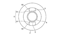
- 3A and 3B are diagrams showing another configuration example of the torque sensor according to Embodiment 1 of the present invention
- FIG. 3A is a front view
- FIG. 3B is a side sectional view.
- FIG. 3 is a diagram showing another configuration example of the torque sensor according to Embodiment 1 of the present invention.
- 5A and 5B are diagrams showing another configuration example of the torque sensor according to Embodiment 1 of the present invention.
- FIG. 1A is a front view
- FIG. 1B is a side sectional view.
- FIG. 3 is a diagram showing another configuration example of the torque sensor according to Embodiment 1 of the present
- FIG. 5A is a front view
- FIG. 5B is a side sectional view
- 6A and 6B are diagrams showing a configuration example of the torque sensor according to Embodiment 1 of the present invention
- FIG. 6A is a front view
- FIG. 6B is a side sectional view
- FIG. 4 is a front view showing another example of the configuration of the torque sensor according to Embodiment 1 of the present invention. It is a front view showing the example of composition of the torque sensor which has no projection in a torque transmission part.
- FIG. 1 is a diagram showing a configuration example of a torque sensor according to Embodiment 1 of the present invention.
- the torque sensor detects a torque.
- the torque sensor includes a flange (first flange) 2 connected to one end of the outer cylinder 1 and a flange (second flange) 3 connected to the other end of the outer cylinder 1.
- the outer cylinder part 1, the flange 2 and the flange 3 are made of, for example, stainless steel.
- a drive system such as a motor is connected to one of the flanges 2 and 3, and a load system such as a robot hand is connected to the other.
- the torque sensor has an inner cylinder 4 located on the same axis (including substantially the same meaning) as the outer cylinder 1.
- One or more sensor elements 5 are attached to the outer peripheral surface of the inner cylindrical portion 4.
- the sensor element 5 outputs a signal corresponding to an external shear stress.
- the sensor element 5 has a resistance gauge oriented obliquely (45 degrees) with respect to the axis. Note that the oblique direction is a 45-degree direction, but is not limited to this, and a certain degree of deviation (for example, a 44-degree direction or a 46-degree direction) is allowed. Further, as shown in FIG. 1, the two sensor elements 5 are provided so as to face each other with the inner cylindrical portion 4 interposed therebetween, so that the torque sensor can reduce interference with other axes. Further, as the sensor element 5, for example, a semiconductor strain gauge or a metal strain gauge can be used.
- the torque sensor has a torque transmitting portion (first torque transmitting portion) 6 having one end connected to the inner peripheral surface of the flange 2 and the other end connected to the outer peripheral surface on one end side of the inner cylindrical portion 4.
- the torque transmitting section 6 is a thin plate member for transmitting torque generated by an external force applied to the flange 2 to the sensor element 5 via the inner cylindrical section 4. Further, the torque transmitting portion 6 has a space in a direction excluding the direction in which the sensor element 5 is located in the radial direction with respect to the axis. Further, the torque transmitting section 6 has a projecting section. In FIG. 1, the torque transmitting section 6 is composed of four plate members 61 having a circumferentially undulating projection.
- the two plate members 61 of the four plate members 61 are respectively located in the direction in which the two sensor elements 5 are located in the radial direction with respect to the axis, and the remaining two plate members 61 are disposed. Are located in directions perpendicular to the direction in which the sensor element 5 is located.
- the protrusion of the torque transmitting section 6 does not need to be provided in the radial direction with respect to the axis, and may be in any direction.
- the torque sensor has a torque transmitting section (second torque transmitting section) 7 having one end connected to the inner peripheral surface of the flange 3 and the other end connected to the outer peripheral surface on the other end side of the inner cylindrical portion 4.
- the torque transmitting section 7 is a thin plate member for transmitting torque generated by an external force applied to the flange 3 to the sensor element 5 via the inner cylindrical section 4. Further, the torque transmitting portion 7 has a space in a direction other than the direction in which the sensor element 5 is located in the radial direction with respect to the axis.
- the torque transmitting section 7 has a protruding section.
- the torque transmitting portion 7 is constituted by four plate members 71 having a circumferentially wavy projecting portion.
- the two plate members 71 of the four plate members 71 are respectively positioned in the direction in which the two sensor elements 5 are positioned in the radial direction with respect to the axis, and the remaining two plate members 71 Are located in directions perpendicular to the direction in which the sensor element 5 is located.
- the protrusion of the torque transmitting section 7 does not need to be provided in the radial direction with respect to the axis, and may be in any direction.
- the torque sensor has a measuring unit 8 (not shown) that measures a signal output from the sensor element 5 as torque.
- the measurement unit 8 measures a calculated value of a signal output from each sensor element 5 as torque.
- the measuring unit 8 is realized by a processing circuit such as a system LSI (Large Scale Integration) or a CPU (Central Processing Unit) that executes a program stored in a memory or the like.
- the torque transmitting portion 6 is composed of four plate members 61 each having a circumferentially corrugated protrusion, and the plate members 61 are arranged in a cross shape.
- the shape and arrangement of the torque transmitting section 6 are not limited to this, and a space exists in a direction other than the direction in which the sensor element 5 is located in the radial direction with respect to the axis, and the radial direction in which the space exists is present. It is sufficient that at least a part of the position has a protruding portion, and for example, the shape and the arrangement as shown in FIGS.
- the torque transmitting portion 6 is composed of four plate members 61 having a linearly wavy projecting portion.
- the arrangement of each plate member 61 is the same as that in FIG.
- the torque transmitting portion 6 is constituted by four plate members 61 having a wide portion 62 as a projecting portion.
- the wide portion 62 extends in a direction perpendicular to the radial direction with respect to the axis.
- the arrangement of each plate member 61 is the same as that in FIG.
- the torque transmitting section 6 is constituted by two plate members 61 having a wide section 62 as a projecting section.
- the wide portion 62 extends in a direction perpendicular to the radial direction with respect to the axis.
- the plate member 61 is located in a direction in which two sensor elements 5 are located in a radial direction with respect to the axis.
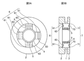
- the torque transmitting portion 6 is constituted by four plate members 61 having a thick portion 63 as a projecting portion.
- the arrangement of each plate member 61 is the same as that in FIG.
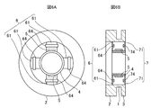
- the torque transmitting portion 6 is composed of four plate members 61, and a separate attaching member 64 is attached to the plate member 61 with an adhesive or the like to form a thick portion 63.
- the arrangement of each plate member 61 is the same as that in FIG.
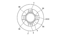
- the torque transmitting portion 6 is composed of a disk member 65 having a circumferentially wavy protruding portion, and arcuate concave portions 66 are formed in four directions on the outer peripheral surface of the disk member 65.
- the torque transmitting portion 6 is connected to the entire outer peripheral surface on one end side of the inner cylindrical portion 4 and is connected to a part of the inner peripheral surface of the flange 2.
- the torque transmission efficiency is improved as compared with the torque sensors shown in FIGS.
- Reference numeral 72 shown in FIG. 3 is a wide portion included in the torque transmitting unit 7.
- Reference numeral 73 shown in FIG. 5 is a thick portion provided in the torque transmitting unit 7.
- Reference numeral 74 shown in FIG. 6 is a retrofit member included in the torque transmission unit 7.
- the torque sensor shown in FIG. 8 has a configuration in which no protrusion is present in the torque transmitting unit 6 and the torque transmitting unit 7 of the torque sensor shown in FIG.
- the transmission direction of the external force is limited so as not to transmit the external force.
- this torque sensor it is possible to reduce the output error when a radial external force is applied to only one of the flanges 2 and 3.
- the rigidity of the torque transmitting unit 6 and the torque transmitting unit 7 against torsion decreases as the space increases, and an output error occurs in the torque sensor due to the torsion.
- the torque sensor in order to suppress the transmission of deformation of the external force to the sensor element 5, a space is provided between the torque transmitting unit 6 and the torque transmitting unit 7, and the torque transmitting unit 6 and the torque transmitting unit 7 Rigidity against torsion is important. Therefore, in the torque sensor according to the first embodiment, the space and the protrusion are provided in the torque transmitting unit 6 and the torque transmitting unit 7. Thus, despite the space, the torque transmitting unit 6 and the torque transmitting unit 7 have increased rigidity against torsion, and the torque sensor can realize a reduction in output error due to the torsion. Therefore, it is sufficient that the space and the protruding portion are provided only in the torque transmitting portion on the flange side of the torque transmitting portions 6 and 7 to which a tension or a compressive force is applied.
- the torque sensor includes the outer cylinder 1, the flange 2 connected to one end of the outer cylinder 1, and the flange 2 connected to the other end of the outer cylinder 1. 3, an inner cylinder part 4 located on the same axis as the outer cylinder part 1, and a sensor element 5 provided on the outer peripheral surface of the inner cylinder part 4 and having a resistance gauge directed obliquely to the axis.
- One end is connected to the inner peripheral surface of the flange 2, and the other end is a thin plate member connected to the outer peripheral surface on one end side of the inner cylindrical portion 4.
- a torque transmitting portion 7 which is a thin plate member, the other end of which is connected to the outer peripheral surface on the other end side of the inner cylindrical portion 4.
- At least one of the torque transmitting portion 6 and the torque transmitting portion 7 has a shaft.
- a space exists in a direction other than the direction in which the sensor element 5 is located in the radial direction with respect to the center, and the space exists. Having a ledge on at least a portion of that radial position.
- any constituent element of the embodiment can be modified or any constituent element of the embodiment can be omitted.
- the torque sensor according to the present invention can reduce an output error due to twisting of a torque transmitting unit having a space, and is suitable for use as a torque sensor for detecting torque.
Landscapes
- Physics & Mathematics (AREA)
- General Physics & Mathematics (AREA)
- Manipulator (AREA)
- Force Measurement Appropriate To Specific Purposes (AREA)
- Power Steering Mechanism (AREA)
Abstract
外筒部(1)と、外筒部(1)の一端に連結されたフランジ(2)と、外筒部(1)の他端に連結されたフランジ(3)と、外筒部(1)と同一の軸心上に位置する内筒部(4)と、内筒部(4)の外周面に設けられ、軸心に対して斜め方向を向いた抵抗ゲージを有するセンサ素子(5)と、一端がフランジ(2)の内周面に連結され、他端が内筒部(4)の一端側の外周面に連結された薄板部材であるトルク伝達部(6)と、一端がフランジ(3)の内周面に連結され、他端が内筒部(4)の他端側の外周面に連結された薄板部材であるトルク伝達部(7)とを備え、トルク伝達部(6)及びトルク伝達部(7)のうちの少なくとも一方は、軸心に対する径方向のうちのセンサ素子(5)が位置する方向を除く方向に空間が存在し、且つ、当該空間が存在する径方向位置の少なくとも一部に出っ張り部を有する。
Description
この発明は、トルクを検出するトルクセンサに関する。
従来から、回転軸体の外周面に取付けられたセンサ素子を有し、トルクにより回転軸体の外周面に生じるせん断応力の大きさを、センサ素子における抵抗値変化により検出するトルクセンサがある(例えば特許文献1参照)。
また、回転軸体を外筒部及びその両端に連結された2枚のフランジから構成し、各フランジにディスク状のトルク伝達部を介して連結された内筒部を設け、この内筒部の外周面にセンサ素子が取付けられたトルクセンサも知られている。
また、回転軸体を外筒部及びその両端に連結された2枚のフランジから構成し、各フランジにディスク状のトルク伝達部を介して連結された内筒部を設け、この内筒部の外周面にセンサ素子が取付けられたトルクセンサも知られている。
一方、トルクセンサには、用途によっては、一端のみに径方向の外力(張力又は圧縮力)が加わる場合がある。この場合、トルク伝達部を有するトルクセンサでは、外力の方向とセンサ素子の位置との関係によっては出力誤差が生じるため、改善が必要である。
これに対し、トルク伝達部に空間を設けて外力の伝達方向を限定することで、トルクセンサでの出力誤差を低減する方法が考えられる。しかしながら、トルク伝達部は空間が大きくなるとねじれに対する剛性が下がり、このねじれによってトルクセンサに出力誤差が生じる。
これに対し、トルク伝達部に空間を設けて外力の伝達方向を限定することで、トルクセンサでの出力誤差を低減する方法が考えられる。しかしながら、トルク伝達部は空間が大きくなるとねじれに対する剛性が下がり、このねじれによってトルクセンサに出力誤差が生じる。
この発明は、上記のような課題を解決するためになされたもので、空間を有するトルク伝達部のねじれによる出力誤差を低減可能とするトルクセンサを提供することを目的としている。
この発明に係るトルクセンサは、外筒部と、外筒部の一端に連結された第1フランジと、外筒部の他端に連結された第2フランジと、外筒部と同一の軸心上に位置する内筒部と、内筒部の外周面に設けられ、軸心に対して斜め方向を向いた抵抗ゲージを有するセンサ素子と、一端が第1フランジの内周面に連結され、他端が内筒部の一端側の外周面に連結された薄板部材である第1トルク伝達部と、一端が第2フランジの内周面に連結され、他端が内筒部の他端側の外周面に連結された薄板部材である第2トルク伝達部とを備え、第1トルク伝達部及び第2トルク伝達部のうちの少なくとも一方は、軸心に対する径方向のうちのセンサ素子が位置する方向を除く方向に空間が存在し、且つ、当該空間が存在する径方向位置の少なくとも一部に出っ張り部を有することを特徴とする。
この発明によれば、上記のように構成したので、空間を有するトルク伝達部のねじれによる出力誤差を低減可能となる。
以下、この発明の実施の形態について図面を参照しながら詳細に説明する。
実施の形態1.
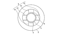
図1はこの発明の実施の形態1に係るトルクセンサの構成例を示す図である。
トルクセンサは、トルクを検出する。このトルクセンサは、図1に示すように、外筒部1の一端に連結されたフランジ(第1フランジ)2と、外筒部1の他端に連結されたフランジ(第2フランジ)3とを有している。外筒部1、フランジ2及びフランジ3は、例えばステンレスにより構成される。なお、フランジ2及びフランジ3のうちの一方にはモータ等の駆動系が接続され、他方には例えばロボットハンド等の負荷系が接続される。
実施の形態1.
図1はこの発明の実施の形態1に係るトルクセンサの構成例を示す図である。
トルクセンサは、トルクを検出する。このトルクセンサは、図1に示すように、外筒部1の一端に連結されたフランジ(第1フランジ)2と、外筒部1の他端に連結されたフランジ(第2フランジ)3とを有している。外筒部1、フランジ2及びフランジ3は、例えばステンレスにより構成される。なお、フランジ2及びフランジ3のうちの一方にはモータ等の駆動系が接続され、他方には例えばロボットハンド等の負荷系が接続される。
また、トルクセンサは、外筒部1と同一(略同一の意味を含む)の軸心上に位置する内筒部4を有している。この内筒部4の外周面には、1つ以上のセンサ素子5が貼付けられている。センサ素子5は、外部からのせん断応力に応じた信号を出力する。このセンサ素子5は、上記軸心に対して斜め方向(45度方向)を向いた抵抗ゲージを有する。なお、斜め方向は45度方向としているが、これに限らず、ある程度のずれ(例えば44度方向又は46度方向等)は許容される。また図1に示すように、内筒部4を挟んで対向するように2つのセンサ素子5が設けられることで、トルクセンサは他軸干渉を低減可能となる。また、センサ素子5としては、例えば半導体歪ゲージ又は金属歪ゲージを用いることができる。
また、トルクセンサは、一端がフランジ2の内周面に連結され、他端が内筒部4の一端側の外周面に連結されたトルク伝達部(第1トルク伝達部)6を有する。トルク伝達部6は、フランジ2に加えられた外力により生じるトルクを内筒部4を介してセンサ素子5に伝達するための薄板部材である。また、トルク伝達部6には、上記軸心に対する径方向のうちのセンサ素子5が位置する方向を除く方向に空間が存在する。また、トルク伝達部6は、出っ張り部を有している。図1では、トルク伝達部6が円周状に波形の出っ張り部を有する4枚の板部材61から構成されている。そして、4枚の板部材61のうちの2枚の板部材61は、上記軸心に対する径方向のうちの2つのセンサ素子5が位置する方向にそれぞれ位置し、残りの2枚の板部材61は、当該センサ素子5が位置する方向に対して垂直な方向にそれぞれ位置している。なお、トルク伝達部6が有する出っ張り部は上記軸心に対する径方向に設けられている必要はなく、任意の向きでよい。
また、トルクセンサは、一端がフランジ3の内周面に連結され、他端が内筒部4の他端側の外周面に連結されたトルク伝達部(第2トルク伝達部)7を有する。トルク伝達部7は、フランジ3に加えられた外力により生じるトルクを内筒部4を介してセンサ素子5に伝達するための薄板部材である。また、トルク伝達部7には、上記軸心に対する径方向のうちのセンサ素子5が位置する方向を除く方向に空間が存在する。また、トルク伝達部7は、出っ張り部を有している。図1では、トルク伝達部7が円周状に波形の出っ張り部を有する4枚の板部材71から構成されている。そして、4枚の板部材71のうちの2枚の板部材71は、上記軸心に対する径方向のうちの2つのセンサ素子5が位置する方向にそれぞれ位置し、残りの2枚の板部材71は、当該センサ素子5が位置する方向に対して垂直な方向にそれぞれ位置している。また、トルク伝達部7が有する出っ張り部は上記軸心に対する径方向に設けられている必要はなく、任意の向きでよい。
また、トルクセンサは、センサ素子5により出力された信号をトルクとして計測する計測部8(不図示)を有する。トルクセンサに2つ以上のセンサ素子5が設けられる場合には、計測部8は、各センサ素子5により出力された信号の演算値をトルクとして計測する。なお、計測部8は、システムLSI(Large Scale Integration)等の処理回路、又はメモリ等に記憶されたプログラムを実行するCPU(Central Processing Unit)等により実現される。
なお図1では、トルク伝達部6が円周状に波形の出っ張り部を有する4枚の板部材61から成り、各板部材61が十字に配置されている。しかしながら、トルク伝達部6の形状及び配置はこれに限らず、上記軸心に対する径方向のうちのセンサ素子5が位置する方向を除く方向に空間が存在し、且つ、当該空間が存在する径方向位置の少なくとも一部に出っ張り部を有していればよく、例えば図2~7に示すような形状及び配置としてもよい。
例えば図2では、トルク伝達部6が直線状に波形の出っ張り部を有する4枚の板部材61から構成されている。なお、各板部材61の配置は図1と同一である。
また図3では、トルク伝達部6が出っ張り部として幅広部62を有する4枚の板部材61から構成されている。幅広部62は、上記軸心に対する径方向に垂直な方向に延びている。なお、各板部材61の配置は図1と同一である。
また図4では、トルク伝達部6が出っ張り部として幅広部62を有する2枚の板部材61から構成されている。幅広部62は、上記軸心に対する径方向に垂直な方向に延びている。そして、この板部材61が、上記軸心に対する径方向のうちの2つのセンサ素子5が位置する方向にそれぞれ位置している。
また図4では、トルク伝達部6が出っ張り部として幅広部62を有する2枚の板部材61から構成されている。幅広部62は、上記軸心に対する径方向に垂直な方向に延びている。そして、この板部材61が、上記軸心に対する径方向のうちの2つのセンサ素子5が位置する方向にそれぞれ位置している。
また図5では、トルク伝達部6が出っ張り部として肉厚部63を有する4枚の板部材61から構成されている。なお、各板部材61の配置は図1と同一である。
また図6では、トルク伝達部6が4枚の板部材61から成り、この板部材61に対して別体の後付け部材64が接着剤等により取付けられることで肉厚部63が構成されている。なお、各板部材61の配置は図1と同一である。
また図6では、トルク伝達部6が4枚の板部材61から成り、この板部材61に対して別体の後付け部材64が接着剤等により取付けられることで肉厚部63が構成されている。なお、各板部材61の配置は図1と同一である。
また図7では、トルク伝達部6が円周状に波形の出っ張り部を有するディスク部材65から成り、ディスク部材65の外周面のうちの4方向に円弧状の凹部66が形成されている。これにより、トルク伝達部6は、内筒部4の一端側の外周面のうちの全周に連結され、且つ、フランジ2の内周面のうちの一部に連結される。その結果、図7に示すトルクセンサでは、図1~6に示すトルクセンサに対し、トルク伝達効率が向上する。
なお上記では、トルク伝達部6の形状及び配置について説明したが、トルク伝達部7の形状及び配置についても同様である。なお、図3に示す符号72はトルク伝達部7が有する幅広部である。また、図5に示す符号73はトルク伝達部7が有する肉厚部である。また、図6に示す符号74はトルク伝達部7が有する後付け部材である。
次に、実施の形態1に係るトルクセンサによる効果について説明する。なお、図8に示すトルクセンサは、図1に示すトルクセンサのトルク伝達部6及びトルク伝達部7に出っ張り部が存在しない構成である。
図8に示すトルクセンサでは、トルク伝達部6及びトルク伝達部7に空間を設けることで、上記軸心に対する径方向のうちのセンサ素子5が感度を有する方向に加えられた外力をセンサ素子5に伝達しないように外力の伝達方向を限定している。これにより、このトルクセンサでは、フランジ2及びフランジ3のうちの一方にのみに径方向の外力が加わった場合での出力誤差の低減を実現可能となる。しかしながら、この場合、トルク伝達部6及びトルク伝達部7は空間が大きくなるとねじれに対する剛性が下がり、このねじれによってトルクセンサに出力誤差が生じる。
図8に示すトルクセンサでは、トルク伝達部6及びトルク伝達部7に空間を設けることで、上記軸心に対する径方向のうちのセンサ素子5が感度を有する方向に加えられた外力をセンサ素子5に伝達しないように外力の伝達方向を限定している。これにより、このトルクセンサでは、フランジ2及びフランジ3のうちの一方にのみに径方向の外力が加わった場合での出力誤差の低減を実現可能となる。しかしながら、この場合、トルク伝達部6及びトルク伝達部7は空間が大きくなるとねじれに対する剛性が下がり、このねじれによってトルクセンサに出力誤差が生じる。
ここで、トルクセンサでは、上記外力のセンサ素子5への変形伝達を抑制するためには、トルク伝達部6及びトルク伝達部7の空間を設けることと、トルク伝達部6及びトルク伝達部7のねじれに対する剛性が重要となる。
そこで、実施の形態1に係るトルクセンサでは、トルク伝達部6及びトルク伝達部7に上記空間及び出っ張り部を設ける。これにより、空間があるにも関わらず、トルク伝達部6及びトルク伝達部7はねじれに対する剛性が増し、トルクセンサはこのねじれによる出力誤差の低減を実現可能となる。したがって、上記空間及び出っ張り部は、トルク伝達部6、7のうちの、張力又は圧縮力が加わるフランジ側のトルク伝達部にのみ設けられていれば十分である。
そこで、実施の形態1に係るトルクセンサでは、トルク伝達部6及びトルク伝達部7に上記空間及び出っ張り部を設ける。これにより、空間があるにも関わらず、トルク伝達部6及びトルク伝達部7はねじれに対する剛性が増し、トルクセンサはこのねじれによる出力誤差の低減を実現可能となる。したがって、上記空間及び出っ張り部は、トルク伝達部6、7のうちの、張力又は圧縮力が加わるフランジ側のトルク伝達部にのみ設けられていれば十分である。
以上のように、この実施の形態1によれば、トルクセンサは、外筒部1と、外筒部1の一端に連結されたフランジ2と、外筒部1の他端に連結されたフランジ3と、外筒部1と同一の軸心上に位置する内筒部4と、内筒部4の外周面に設けられ、軸心に対して斜め方向を向いた抵抗ゲージを有するセンサ素子5と、一端がフランジ2の内周面に連結され、他端が内筒部4の一端側の外周面に連結された薄板部材であるトルク伝達部6と、一端がフランジ3の内周面に連結され、他端が内筒部4の他端側の外周面に連結された薄板部材であるトルク伝達部7とを備え、トルク伝達部6及びトルク伝達部7のうちの少なくとも一方は、軸心に対する径方向のうちのセンサ素子5が位置する方向を除く方向に空間が存在し、且つ、当該空間が存在する径方向位置の少なくとも一部に出っ張り部を有する。これにより、実施の形態1に係るトルクセンサは、ねじれによる出力誤差を低減可能となる。
なお、本願発明はその発明の範囲内において、実施の形態の任意の構成要素の変形、もしくは実施の形態の任意の構成要素の省略が可能である。
この発明に係るトルクセンサは、空間を有するトルク伝達部のねじれによる出力誤差を低減可能となり、トルクを検出するトルクセンサに用いるのに適している。
1 外筒部
2 フランジ(第1フランジ)
3 フランジ(第2フランジ)
4 内筒部
5 センサ素子
6 トルク伝達部(第1トルク伝達部)
7 トルク伝達部(第2トルク伝達部)
8 計測部
61 板部材
62 幅広部
63 肉厚部
64 後付け部材
65 ディスク部材
66 凹部
71 板部材
72 幅広部
73 肉厚部
74 後付け部材
2 フランジ(第1フランジ)
3 フランジ(第2フランジ)
4 内筒部
5 センサ素子
6 トルク伝達部(第1トルク伝達部)
7 トルク伝達部(第2トルク伝達部)
8 計測部
61 板部材
62 幅広部
63 肉厚部
64 後付け部材
65 ディスク部材
66 凹部
71 板部材
72 幅広部
73 肉厚部
74 後付け部材
Claims (8)
- 外筒部と、
前記外筒部の一端に連結された第1フランジと、
前記外筒部の他端に連結された第2フランジと、
前記外筒部と同一の軸心上に位置する内筒部と、
前記内筒部の外周面に設けられ、前記軸心に対して斜め方向を向いた抵抗ゲージを有するセンサ素子と、
一端が前記第1フランジの内周面に連結され、他端が前記内筒部の一端側の外周面に連結された薄板部材である第1トルク伝達部と、
一端が前記第2フランジの内周面に連結され、他端が前記内筒部の他端側の外周面に連結された薄板部材である第2トルク伝達部とを備え、
前記第1トルク伝達部及び前記第2トルク伝達部のうちの少なくとも一方は、前記軸心に対する径方向のうちの前記センサ素子が位置する方向を除く方向に空間が存在し、且つ、当該空間が存在する径方向位置の少なくとも一部に出っ張り部を有する
ことを特徴とするトルクセンサ。 - 前記第1トルク伝達部及び前記第2トルク伝達部のうちの前記空間を有するトルク伝達部は、前記他端が、前記内筒部の外周面のうちの全周に連結された
ことを特徴とする請求項1記載のトルクセンサ。 - 前記第1トルク伝達部及び前記第2トルク伝達部のうちの前記空間を有するトルク伝達部は、前記一端が、前記第1フランジ及び前記第2フランジのうちの連結対象である一方のフランジの内周面のうちの一部に連結された
ことを特徴とする請求項1又は請求項2記載のトルクセンサ。 - 前記センサ素子は、前記内筒部を挟んで対向した2つのセンサ素子である
ことを特徴とする請求項1から請求項3のうちの何れか1項記載のトルクセンサ。 - 前記出っ張り部は波形である
ことを特徴とする請求項1から請求項4のうちの何れか1項記載のトルクセンサ。 - 前記第1トルク伝達部及び前記第2トルク伝達部のうちの前記空間を有するトルク伝達部は、幅広部を前記出っ張り部として有する板部材である
ことを特徴とする請求項1から請求項4のうちの何れか1項記載のトルクセンサ。 - 前記出っ張り部は、前記第1トルク伝達部及び前記第2トルク伝達部のうちの前記空間を有するトルク伝達部の肉厚部である
ことを特徴とする請求項1から請求項4のうちの何れか1項記載のトルクセンサ。 - 前記肉厚部は、前記薄板部材に別体の後付け部材が取付けられることで構成された
ことを特徴とする請求項7記載のトルクセンサ。
Priority Applications (2)
| Application Number | Priority Date | Filing Date | Title |
|---|---|---|---|
| CN201980040889.7A CN112334745B (zh) | 2018-07-03 | 2019-06-13 | 扭矩传感器 |
| KR1020207034887A KR102377663B1 (ko) | 2018-07-03 | 2019-06-13 | 토크 센서 |
Applications Claiming Priority (2)
| Application Number | Priority Date | Filing Date | Title |
|---|---|---|---|
| JP2018-126948 | 2018-07-03 | ||
| JP2018126948A JP7021835B2 (ja) | 2018-07-03 | 2018-07-03 | トルクセンサ |
Publications (1)
| Publication Number | Publication Date |
|---|---|
| WO2020008837A1 true WO2020008837A1 (ja) | 2020-01-09 |
Family
ID=69060801
Family Applications (1)
| Application Number | Title | Priority Date | Filing Date |
|---|---|---|---|
| PCT/JP2019/023523 Ceased WO2020008837A1 (ja) | 2018-07-03 | 2019-06-13 | トルクセンサ |
Country Status (4)
| Country | Link |
|---|---|
| JP (1) | JP7021835B2 (ja) |
| KR (1) | KR102377663B1 (ja) |
| CN (1) | CN112334745B (ja) |
| WO (1) | WO2020008837A1 (ja) |
Citations (5)
| Publication number | Priority date | Publication date | Assignee | Title |
|---|---|---|---|---|
| JPS4868592U (ja) * | 1971-12-01 | 1973-08-31 | ||
| US4608861A (en) * | 1984-11-07 | 1986-09-02 | Macleod Laboratories, Inc. | MWD tool for measuring weight and torque on bit |
| US5033314A (en) * | 1989-11-06 | 1991-07-23 | Spar Aerospace Limited | Force and moment sensor |
| JP2002502962A (ja) * | 1998-02-04 | 2002-01-29 | エス.エヌ.エール.ルールマン | 回転シャフトのためのトルクセンサ |
| WO2018041934A1 (de) * | 2016-08-31 | 2018-03-08 | Sensodrive Gmbh | Drehmomentsensor mit dichtungsmembran |
Family Cites Families (9)
| Publication number | Priority date | Publication date | Assignee | Title |
|---|---|---|---|---|
| JPS6033171A (ja) * | 1983-08-04 | 1985-02-20 | Komatsu Ltd | 装軌式車両のスプロケツト装置 |
| JP2002139391A (ja) * | 2000-11-02 | 2002-05-17 | Exedy Corp | トルク検出装置 |
| JP2003336689A (ja) * | 2002-05-21 | 2003-11-28 | Exedy Corp | フライホイール組立体 |
| JP2004132748A (ja) * | 2002-10-09 | 2004-04-30 | Unisia Jkc Steering System Co Ltd | 電動パワーステアリング装置のトルクセンサ |
| US7665373B2 (en) * | 2008-06-18 | 2010-02-23 | Kop-Flex Inc. | Torque measuring device with redundant torque transmission paths and fail-safe mechanism |
| JP5475918B1 (ja) * | 2013-10-24 | 2014-04-16 | 株式会社東京鋲兼 | トルクヒンジ又はトルクリミッタ |
| JP6293111B2 (ja) * | 2015-12-16 | 2018-03-14 | 本田技研工業株式会社 | トルク伝達装置 |
| JP2017172983A (ja) * | 2016-03-18 | 2017-09-28 | 株式会社安川電機 | ロボット及びトルクセンサ |
| DE102016010551B3 (de) * | 2016-08-31 | 2018-02-08 | Sensodrive Gmbh | Drehmomentsensor mit radialelastischer Momentübertragung |
-
2018
- 2018-07-03 JP JP2018126948A patent/JP7021835B2/ja active Active
-
2019
- 2019-06-13 WO PCT/JP2019/023523 patent/WO2020008837A1/ja not_active Ceased
- 2019-06-13 KR KR1020207034887A patent/KR102377663B1/ko active Active
- 2019-06-13 CN CN201980040889.7A patent/CN112334745B/zh active Active
Patent Citations (5)
| Publication number | Priority date | Publication date | Assignee | Title |
|---|---|---|---|---|
| JPS4868592U (ja) * | 1971-12-01 | 1973-08-31 | ||
| US4608861A (en) * | 1984-11-07 | 1986-09-02 | Macleod Laboratories, Inc. | MWD tool for measuring weight and torque on bit |
| US5033314A (en) * | 1989-11-06 | 1991-07-23 | Spar Aerospace Limited | Force and moment sensor |
| JP2002502962A (ja) * | 1998-02-04 | 2002-01-29 | エス.エヌ.エール.ルールマン | 回転シャフトのためのトルクセンサ |
| WO2018041934A1 (de) * | 2016-08-31 | 2018-03-08 | Sensodrive Gmbh | Drehmomentsensor mit dichtungsmembran |
Also Published As
| Publication number | Publication date |
|---|---|
| KR20210002719A (ko) | 2021-01-08 |
| JP2020008325A (ja) | 2020-01-16 |
| JP7021835B2 (ja) | 2022-02-17 |
| CN112334745B (zh) | 2022-03-04 |
| CN112334745A (zh) | 2021-02-05 |
| KR102377663B1 (ko) | 2022-03-24 |
Similar Documents
| Publication | Publication Date | Title |
|---|---|---|
| CN109642836B (zh) | 具有径向弹性力矩传递的扭矩传感器 | |
| KR102353857B1 (ko) | 션트 스포크를 구비하는 토크 센서 | |
| CN109661566B (zh) | 具有密封膜的扭矩传感器 | |
| JP2017172983A (ja) | ロボット及びトルクセンサ | |
| CN105606279B (zh) | 弹性力矩传感器 | |
| EP3822603A1 (en) | Torque sensor | |
| US20090056473A1 (en) | Torque sensor for a steering wheel | |
| JP2002139391A (ja) | トルク検出装置 | |
| WO2020008837A1 (ja) | トルクセンサ | |
| WO2020008836A1 (ja) | トルクセンサ | |
| CN112313490B (zh) | 扭矩传感器 | |
| JP7587041B2 (ja) | トルクセンサ | |
| JPH04230818A (ja) | トルク測定装置 | |
| JP7260095B2 (ja) | 荷重変換器 | |
| JP2023035339A (ja) | トルクセンサ | |
| JP2012127884A (ja) | トルクセンサ及びこれを備えた駆動装置 | |
| TW201726532A (zh) | 荷重檢測器 | |
| JP2021089239A (ja) | トルクセンサ | |
| JP2023035338A (ja) | トルクセンサ | |
| JP2021089199A (ja) | トルクセンサ | |
| JP2023157443A (ja) | トルクセンサ | |
| WO2024185440A1 (ja) | トルクセンサ | |
| WO2025084015A1 (ja) | トルクセンサ | |
| JP2019105559A (ja) | トルク検出機構 | |
| JP2023128933A (ja) | トルクセンサ |
Legal Events
| Date | Code | Title | Description |
|---|---|---|---|
| 121 | Ep: the epo has been informed by wipo that ep was designated in this application |
Ref document number: 19829992 Country of ref document: EP Kind code of ref document: A1 |
|
| ENP | Entry into the national phase |
Ref document number: 20207034887 Country of ref document: KR Kind code of ref document: A |
|
| NENP | Non-entry into the national phase |
Ref country code: DE |
|
| 122 | Ep: pct application non-entry in european phase |
Ref document number: 19829992 Country of ref document: EP Kind code of ref document: A1 |