WO2020008683A1 - 無線給電装置及び無線給電システム - Google Patents
無線給電装置及び無線給電システム Download PDFInfo
- Publication number
- WO2020008683A1 WO2020008683A1 PCT/JP2019/009515 JP2019009515W WO2020008683A1 WO 2020008683 A1 WO2020008683 A1 WO 2020008683A1 JP 2019009515 W JP2019009515 W JP 2019009515W WO 2020008683 A1 WO2020008683 A1 WO 2020008683A1
- Authority
- WO
- WIPO (PCT)
- Prior art keywords
- power supply
- signal
- weight
- antenna
- wireless power
- Prior art date
- Legal status (The legal status is an assumption and is not a legal conclusion. Google has not performed a legal analysis and makes no representation as to the accuracy of the status listed.)
- Ceased
Links
Images



Classifications
-
- H—ELECTRICITY
- H02—GENERATION; CONVERSION OR DISTRIBUTION OF ELECTRIC POWER
- H02J—ELECTRIC POWER NETWORKS; CIRCUIT ARRANGEMENTS OR SYSTEMS FOR SUPPLYING OR DISTRIBUTING ELECTRIC POWER; SYSTEMS FOR STORING ELECTRIC ENERGY
- H02J50/00—Circuit arrangements or systems for wireless supply or distribution of electric power
- H02J50/40—Circuit arrangements or systems for wireless supply or distribution of electric power using two or more transmitting or receiving devices
- H02J50/402—Circuit arrangements or systems for wireless supply or distribution of electric power using two or more transmitting or receiving devices the two or more transmitting or the two or more receiving devices being integrated in the same unit, e.g. power mats with several coils or antennas with several sub-antennas
-
- G—PHYSICS
- G06—COMPUTING OR CALCULATING; COUNTING
- G06K—GRAPHICAL DATA READING; PRESENTATION OF DATA; RECORD CARRIERS; HANDLING RECORD CARRIERS
- G06K7/00—Methods or arrangements for sensing record carriers, e.g. for reading patterns
- G06K7/10—Methods or arrangements for sensing record carriers, e.g. for reading patterns by electromagnetic radiation, e.g. optical sensing; by corpuscular radiation
-
- H—ELECTRICITY
- H01—ELECTRIC ELEMENTS
- H01Q—ANTENNAS, i.e. RADIO AERIALS
- H01Q21/00—Antenna arrays or systems
- H01Q21/06—Arrays of individually energised antenna units similarly polarised and spaced apart
-
- H—ELECTRICITY
- H01—ELECTRIC ELEMENTS
- H01Q—ANTENNAS, i.e. RADIO AERIALS
- H01Q3/00—Arrangements for changing or varying the orientation or the shape of the directional pattern of the waves radiated from an antenna or antenna system
- H01Q3/26—Arrangements for changing or varying the orientation or the shape of the directional pattern of the waves radiated from an antenna or antenna system varying the relative phase or relative amplitude of energisation between two or more active radiating elements; varying the distribution of energy across a radiating aperture
-
- H—ELECTRICITY
- H02—GENERATION; CONVERSION OR DISTRIBUTION OF ELECTRIC POWER
- H02J—ELECTRIC POWER NETWORKS; CIRCUIT ARRANGEMENTS OR SYSTEMS FOR SUPPLYING OR DISTRIBUTING ELECTRIC POWER; SYSTEMS FOR STORING ELECTRIC ENERGY
- H02J50/00—Circuit arrangements or systems for wireless supply or distribution of electric power
- H02J50/20—Circuit arrangements or systems for wireless supply or distribution of electric power using microwaves or radio frequency waves
-
- H—ELECTRICITY
- H02—GENERATION; CONVERSION OR DISTRIBUTION OF ELECTRIC POWER
- H02J—ELECTRIC POWER NETWORKS; CIRCUIT ARRANGEMENTS OR SYSTEMS FOR SUPPLYING OR DISTRIBUTING ELECTRIC POWER; SYSTEMS FOR STORING ELECTRIC ENERGY
- H02J50/00—Circuit arrangements or systems for wireless supply or distribution of electric power
- H02J50/80—Circuit arrangements or systems for wireless supply or distribution of electric power involving the exchange of data, concerning supply or distribution of electric power, between transmitting devices and receiving devices
-
- H—ELECTRICITY
- H02—GENERATION; CONVERSION OR DISTRIBUTION OF ELECTRIC POWER
- H02J—ELECTRIC POWER NETWORKS; CIRCUIT ARRANGEMENTS OR SYSTEMS FOR SUPPLYING OR DISTRIBUTING ELECTRIC POWER; SYSTEMS FOR STORING ELECTRIC ENERGY
- H02J7/00—Circuit arrangements for charging or discharging batteries or for supplying loads from batteries
-
- H—ELECTRICITY
- H04—ELECTRIC COMMUNICATION TECHNIQUE
- H04B—TRANSMISSION
- H04B5/00—Near-field transmission systems, e.g. inductive or capacitive transmission systems
- H04B5/40—Near-field transmission systems, e.g. inductive or capacitive transmission systems characterised by components specially adapted for near-field transmission
- H04B5/48—Transceivers
Definitions
- the present invention relates to a wireless power supply device and a wireless power supply system.
- the wireless data communication between the RFID tag and the RFID reader and the wireless power supply from the RFID reader to the RFID tag are performed by using the RFID (Radio Frequency IDentifier) technology.
- RFID Radio Frequency IDentifier
- For wireless data communication and wireless power supply for example, an array antenna in which a plurality of antenna elements are regularly arranged is provided in an RFID reader.
- JP 2015-164318 A Japanese Patent Publication No. 2008-204061
- Patent Document 1 the phase and the amplitude of the radio wave transmitted from each antenna element of the array antenna are searched according to a predetermined search algorithm.
- execution of a search by a search algorithm requires time. Therefore, the throughput is reduced, and it takes time to supply power.
- the method using the search algorithm adjusts the radio wave transmitted from each antenna element in response to the change in the propagation environment promptly.
- Patent Document 2 a search by a search algorithm is not performed, a signal from a power supply target device is received, a path difference between an antenna of the power supply target device and each antenna element is detected, and a feed signal of a power supply signal is detected in accordance with the path difference. The phase is being adjusted. However, the amplitude of the power supply signal is not controlled. That is, when power is supplied using the technology disclosed in Patent Document 2, the power supplied to the power supply target device is not maximized, and there is a possibility that the power may be supplied inefficiently.
- the present inventor has found that in the related art, the radio waves transmitted from each antenna element of the array antenna cannot be quickly and efficiently adjusted so as to be efficiently supplied.
- the present invention has been made in view of such circumstances, and an object of the present invention is to adjust radio waves transmitted from each antenna element of an array antenna so that power can be supplied quickly and efficiently. It is to provide a technology that can do it.
- the present invention employs the following configuration in order to solve the above-described problems.
- a wireless power supply device is a wireless power supply device including an array antenna formed from a plurality of antenna elements, and includes a power supply signal generation unit configured to generate a power supply signal; A propagation coefficient calculating unit that calculates respective propagation coefficients between the antenna of the target device and the power supply signal generated by the power supply signal generating unit based on the respective propagation coefficients calculated by the propagation coefficient calculation unit. Weight calculating means for calculating a weight for adjusting the phase and amplitude of a signal for each of the plurality of antenna elements; and the power supply generated by the power supply signal generating means based on the weight calculated by the weight calculating means.
- the phase and the amplitude of the signal are adjusted for each of the plurality of antenna elements, and the feed signal adjusted for each of the plurality of antenna elements is Feed signal distribution means for allocating to the antenna elements, the plurality of antenna elements forming the array antenna convert the distributed power supply signal into a power supply radio wave, and transmit the power supply radio wave to the power supply target device.
- Wireless power supply device Wireless power supply device.
- the weight is calculated based on the propagation coefficient between each antenna element of the wireless power supply apparatus and the antenna of the device to be fed, and the phase of the feed signal is adjusted based on the weight, whereby the phase is adjusted.
- the supplied power signal is distributed to each antenna element.
- the adjustment of the phase is not performed uniformly, but is performed for each of the plurality of antenna elements.
- the power supply signal is converted into a power supply radio wave, and the power supply radio wave is transmitted to the power supply target device.
- the configuration adjusts the phase of the power supply signal according to the propagation environment between each antenna element and the antenna of the power supply target device so that each power supply radio wave received by the power supply target device from each antenna element has the same phase. can do. Therefore, this configuration can improve power supply efficiency to the power supply target device.
- the amplitude of the power supply signal is also adjusted based on the weight. That is, the power supplied from each antenna element to the power supply target device is adjusted. That is, this configuration can maximize the power supplied to the power supply target device according to the propagation environment between each antenna element and the antenna of the power supply target device.
- the processing for adjusting the phase and amplitude of the power supply signal is executed on the wireless power supply apparatus side, not on the power supply target apparatus side.
- the processing for adjusting the phase and amplitude of the power supply signal such as calculation of the propagation coefficient and calculation of the weight
- the result calculated on the power supply target device side is used. It is necessary to transmit to the wireless power supply device side. When such transmission is performed, it is preferable to increase the SNR (Signal Noise Ratio) of the transmission radio wave.
- the power supply target device performs signal processing such as amplification of a transmission signal and removal of noise included in the transmission signal. And, these signal processings require electric power. On the other hand, according to the configuration, such signal processing becomes unnecessary. Therefore, power consumption on the power supply target device side can be reduced. Therefore, such a configuration is an effective configuration when the power supply target device is a device having no battery.
- a request signal for requesting a response to the power supply target device is transmitted to the power supply target device via the plurality of antenna elements forming the array antenna, and the request signal is transmitted to the power supply target device.
- a response signal from the power supply target device is received via the plurality of antenna elements, and the propagation coefficient calculating unit determines whether the plurality of antenna elements and the antenna of the power supply target device are based on the received response signal. May be calculated.
- transmission of the request signal to the power supply target device and reception of the response signal from the power supply target device with respect to the transmitted request signal include power supply to the power supply target device. May be performed each time.
- the configuration can promptly respond to a change in the propagation environment and suppress a decrease in communication reliability.
- the wireless power supply device further comprising a storage unit that sequentially stores the weights calculated by the weight calculation unit, wherein the weight calculation unit is configured to store the weight when the response signal is not received.
- the weight may be predicted based on the stored weights for the predetermined number of times, and the weight calculated based on the propagation coefficient may be substituted by the predicted weight.
- the weight can be predicted based on the weight calculated in the past and stored by the storage unit. Then, by replacing the weight calculated based on the propagation coefficient with the predicted weight, the phase and the amplitude of the power supply signal are adjusted even when the propagation coefficient cannot be calculated.
- the weight is predicted by multiplying a predetermined number of weights stored by the storage unit with a weight prediction coefficient corresponding to each of the predetermined number of weights.
- the weight calculation means when receiving the response signal earlier than when not receiving the response signal, performs the prediction of the weight in addition to the calculation of the weight based on the propagation coefficient, the calculated The weight prediction coefficient may be updated such that a difference between the weight based on the propagation coefficient and the predicted weight is minimized.
- the weight prediction coefficient is optimized so that the difference between the weight calculated based on the propagation coefficient and the predicted weight is minimized. Therefore, even when the weight cannot be calculated based on the propagation coefficient, the weight can be predicted with high accuracy using the weight prediction coefficient.
- the weight prediction coefficient is updated even when the weight is calculated based on the propagation coefficient. That is, even when the propagation environment changes, the accuracy of weight prediction is maintained.
- the power supply signal generation unit may generate a power supply signal to be transmitted to a plurality of power supply target devices.
- the wireless power supply device is a highly convenient device.
- a wireless power supply system includes an antenna, and a modulated signal generation module that, when receiving a radio wave from a device outside the system via the antenna, generates a modulation signal obtained by modulating the received radio wave.
- a wireless power supply apparatus according to the one aspect, further comprising a demodulation unit configured to demodulate the modulated signal when receiving the modulated signal from the powered apparatus. And may be provided.
- the power supply target device when the power supply target device receives the request signal from the wireless power supply device, the power supply target device can generate a modulation signal obtained by modulating the request signal and transmit the modulated signal to the wireless power supply device.
- the power supply target device can transmit a signal to the wireless power supply device without using the oscillator. That is, according to the configuration, power for operating the oscillator in the power supply target device is not required, and power saving is realized.
- the power supply target device can transmit a signal to the wireless power supply device without having a power storage unit that stores power for operating the oscillator, and the cost of parts can be reduced.
- the propagation coefficient calculating means calculates the propagation coefficient based on the request signal transmitted to the power supply target device and the modulation signal received from the power supply target device, and the modulation signal is the request signal. If the frequency is not a modulated signal, there is no difference between the frequency of the request signal and the frequency of the modulated signal, so that the propagation coefficient can be calculated without considering the difference. That is, the propagation coefficient calculation means can easily calculate the propagation coefficient.
- the power supply target device may further include a power storage unit.
- the power supply target device can perform a process that requires a predetermined power regardless of whether power is supplied from the wireless power supply device to the power supply target device.
- the processing requiring predetermined power refers to, for example, when the power supply target apparatus includes an oscillator, processing such as operation of the oscillator, signal amplification, noise removal, or communication with a wireless power supply apparatus.
- the antenna included in the power supply target device may be formed by a plurality of antenna elements.
- the propagation path (path) of the radio wave between the wireless power supply apparatus and the power supply target device is increased, and the radio wave propagated through a plurality of paths can be concentrated on the power supply target device. Therefore, power supply efficiency to the power supply target device is increased.
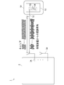
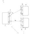
- FIG. 1 schematically illustrates an example of the outline of the wireless power supply system.
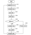
- FIG. 2 schematically illustrates an example of a flowchart showing an outline of the operation of the wireless power supply system.
- FIG. 3 schematically exemplifies an example of a flowchart showing details of a procedure for distributing a power supply signal in the case of initial power supply.
- FIG. 4 schematically illustrates an example of an outline in which a power receiving device generates a modulated signal obtained by modulating a received carrier and transmits the modulated signal to a power supply device.
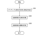
- FIG. 5 schematically illustrates an example of a flowchart illustrating a procedure for estimating a propagation coefficient.
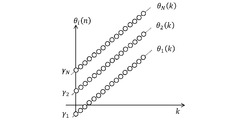
- FIG. 6 schematically illustrates an example of the phase obtained from the preamble portion.
- FIG. 7 schematically illustrates an example of the amplitude obtained from the preamble portion.
- FIG. 8 schematically illustrates an example of an outline of a wireless power feeding system including a power receiving device including a plurality of antenna elements.
- FIG. 9 schematically illustrates an example of the outline of a wireless power supply system that simultaneously supplies power to a plurality of power receiving apparatuses.
- FIG. 1 schematically illustrates an example of the outline of the wireless power supply system 1.
- the wireless power supply system 1 includes a power supply device 2 and a power receiving device 51.
- the power supply device 2 includes an array antenna 3 formed from a plurality of antenna elements 3A.
- the power receiving device 51 includes an antenna 52.
- the power supply device 2 includes a signal generator 4 that generates a power supply signal. Further, the power supply device 2 is provided with a propagation coefficient estimation unit 8 for estimating a propagation coefficient H i of radio waves between the antenna 52 of the i-th antenna element 3A and the power receiving device 51 of the array antenna 3.
- the propagation coefficient is a coefficient representing the amount of attenuation and the amount of phase change of a radio wave when the radio wave propagates between the transmitting and receiving antennas.
- the power supply device 2 includes on the basis of the propagation coefficients H i, the weight calculating unit 9 calculates the weight W i for adjusting the phase and amplitude of the power supply signal generated in the signal generator 4.
- Weight W i is a counterpart for each antenna element 3A, is set to be the relationship of conjugation to the propagation coefficients H i.
- the power supply device 2 adjusts the phase and amplitude of the power supply signal by multiplying the weight calculated by the weight calculation unit 9 by the power supply signal generated by the signal generator 4, and transmits the adjusted power supply signal to each antenna element 3A.
- a power supply signal distribution unit 11 for distributing the power to the power supply.
- each antenna element 3 ⁇ / b> A receives the power supply signal distributed in the power supply signal distribution unit 11 and transmits the distributed power supply signal to the antenna 52 of the power reception device 51, whereby the power reception device 51 Power supply.
- the above-described wireless power supply system 1 appropriately adjusts the phase and amplitude of the power supply signal according to the propagation environment between each antenna element 3A of the power supply device 2 and the antenna 52 of the power reception device 51, It is possible to improve power supply efficiency and maximize power supply.
- the wireless power supply system 1 includes a power supply device 2 and a power receiving device 51.
- the wireless power supply system 1 is an example of the “wireless power supply system” of the present invention.
- the power supply device 2 is an example of the “wireless power supply device” of the present invention.
- the power receiving device 51 is an example of the “power supply target device” of the present invention.
- the power supply device 2 is, for example, an RFID reader, and the power receiving device 51 is, for example, an RFID tag.
- the power receiving device 51 may include various sensor elements that detect a predetermined physical quantity.
- the power supply device 2 includes the array antenna 3.
- the array antenna 3 is formed from a plurality of regularly arranged antenna elements.
- the power supply device 2 includes a signal generator 4 that generates a power supply signal.
- the signal generator 4 is an example of the “feeding signal generating unit” of the present invention.
- the power supply device 2 includes an RF (Radio Frequency) transmission / reception circuit 5 that processes signals transmitted and received via the array antenna 3.
- the power supply device 2 includes a controller and a memory such as a ROM (Read Only Memory) or a RAM (Random Access Memory).
- the RF transmitting / receiving circuit 5 can perform mutual conversion between an RF (Radio Frequency) signal and a BB (Base Band) signal transmitted / received via the array antenna 3, for example. Further, the RF transmission / reception circuit 5 also performs, for example, A / D (Analogue / Digital) conversion processing. Through such mutual conversion processing, the power supply device 2 can perform low-speed digital processing. When receiving a modulated signal obtained by modulating a carrier transmitted from the array antenna 3, the RF transmitting / receiving circuit 5 also performs a process of demodulating the modulated signal.
- the RF transmission / reception circuit 5 is an example of the “demodulation unit” of the present invention.
- the power supply device 2 includes a propagation coefficient estimating unit 8 that estimates a propagation coefficient of a radio wave between the antenna element 3A of the array antenna 3 and the antenna 52 of the power receiving device 51.
- the propagation coefficient estimating unit 8 is an example of the “propagation coefficient calculating unit” of the present invention.
- the propagation coefficient is a coefficient representing the amount of attenuation and the amount of phase change of a radio wave when the radio wave propagates between the transmitting and receiving antennas.
- the propagation coefficient H i between the i-th antenna element 3A and the antenna 52 is expressed by the following equation (1).
- j represents an imaginary unit
- ⁇ i represents the amount of rotation of the phase of the radio wave on the propagation path
- C i represents the attenuation of the amplitude of the radio wave on the propagation path.
- the above-described propagation coefficient Hi is estimated according to the following equation (2).
- the power supply device 2 based on the propagation coefficient H i of the radio wave which is calculated according to equation (2), the weight calculation unit that calculates the weight W i for adjusting the phase and amplitude of the power supply signal generated in the signal generator 4 9 is provided.
- the weight calculator 9 is an example of the “weight calculator” of the present invention.
- the weight Wi is calculated according to the following equation (3).
- weight W i as shown in equation (3), are set so that the propagation coefficient H i and the conjugate.
- the weight W i is a value obtained by adding the squares of all weights W i is set to be 1.
- the power supply device 2 includes a storage unit 10 for storing the weight W i calculated in the weight calculating unit 9 in the memory.
- the storage unit 10 is an example of the “storage unit” of the present invention.
- the power supply device 2, the weight W i calculated in the weight calculating unit 9 adjusts the phase and amplitude of the feeding signal by multiplying the power supply signal generated in the signal generator 4, the antenna is adjusted supply signal
- a power supply signal allocating unit 11 for allocating to the element 3A is provided.
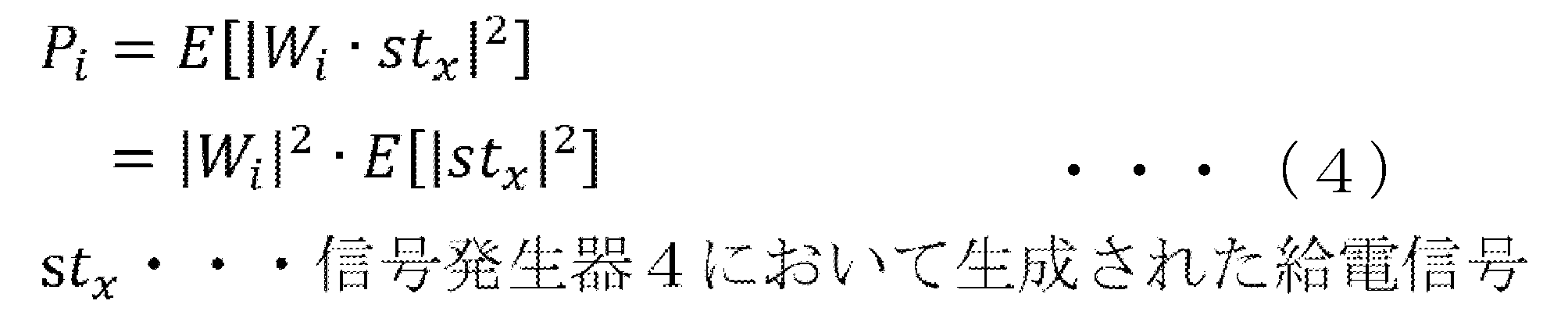
- the power supply signal distribution unit 11 is an example of the “power supply signal distribution unit” of the present invention. Feeding the signal distributing section 11 is distributed to the i-th antenna element 3A, the supplied power P i supplied to the power receiving apparatus 51 is expressed by the following equation (4).
- the power supply device 2 is configured such that the controller executes a control program stored in the memory, and the array antenna 3, the signal generator 4, the RF transmitting / receiving circuit 5, the propagation coefficient estimating unit 8, the weight calculating unit 9, the storage unit 10 , The processing in the power supply signal distribution unit 11 is realized.
- the power receiving device 51 includes an antenna 52.
- the power receiving device 51 is supplied with power by receiving the power supply signal transmitted from the power supply device 2 via the antenna 52.
- the power receiving device 51 includes an RF transmitting / receiving circuit 53.
- the RF transmitting / receiving circuit 53 provided in the power receiving device 51 includes a receiving circuit 55 having a switch 54, and processes a power supply signal received from the power supply device 2 via the antenna 52 and a signal transmitted to the power supply device 2.
- the receiving end circuit 55 is an example of the “modulated signal generating means” of the present invention.
- the power receiving device 51 includes a controller and a memory.
- the controller of the power receiving device 51 does not generate a transmission signal using its own oscillator.
- the controller instead controls the switch of the receiving end circuit 55 to open and short the receiving end circuit 55, modulates the received signal received from the power supply device 2, and transmits the modulated signal to the power supply device 2.
- the controller can control a switch of the receiving end circuit 55, modulate a received radio wave based on a signal generated or detected in the power receiving device 51, and transmit the modulated signal.
- the power receiving device 51 is a batteryless device having no battery.
- the wireless power supply system 1 implements the following operations by causing the controller of the power supply device 2 and the controller of the power receiving device 51 to execute control programs stored in the memories of the respective devices.
- FIG. 2 schematically illustrates an example of a flowchart showing an outline of the operation of the wireless power supply system 1.
- the processing procedure described below is merely an example, and each processing may be changed as much as possible. Further, in the processing procedure described below, steps can be omitted, replaced, or added as appropriate according to the embodiment.
- Step S101 As shown in FIG. 2, in step S101, the signal generator 4 generates an m-th power supply signal.
- the power supply signal is generated such that its power becomes the upper limit of the limit value specified by the Radio Law, for example.
- step S102 the power supply signal is adjusted by multiplying the power supply signal generated by the signal generator 4 by the weight Wi (m) represented by Expression (3) in the power supply signal distribution unit 11.
- the adjusted feed signal is distributed to each antenna element 3A.
- the power feeding signal weights W 1 (m) is multiplied by the power supply signal weights W 1 (m) is multiplied is allocated to the first antenna element 3A.
- the feeding signal weight W 2 (m) is multiplied by the power supply signal weighting W 2 (m) is multiplied is allocated to the second antenna element 3A.
- Such distribution of the power supply signal is executed corresponding to each of the antenna elements 3A.
- FIG. 3 schematically illustrates an example of a flowchart illustrating details of a procedure for calculating the weight Wi (1) in the case of the first power supply.
- the processing procedure described below is merely an example, and each processing may be changed as much as possible. Further, in the processing procedure described below, steps can be omitted, replaced, or added as appropriate according to the embodiment.
- Step S102-1 the weight calculator 9 selects an initial value of the weight for distributing the feed signal to the i-th antenna element 3A from the weight candidate values.
- the weight candidate values are prepared in advance.
- the initial value of the weight may be selected at random or may be selected according to a predetermined method.
- step S102-2 the feed signal generated by the signal generator 4 is multiplied by the initial value of the weight, and the feed signal multiplied by the initial value of the weight is distributed to each antenna element 3A. Such distribution of the power supply signal is executed corresponding to each of the antenna elements 3A.
- Step S102-3 the distributed power supply signal is converted to a high frequency in the RF transmission / reception circuit 5 before reaching the antenna element 3A. Then, a power supply radio wave is generated from the high frequency in each antenna element 3 ⁇ / b> A, and the power supply radio wave is transmitted to the power receiving device 51, thereby performing power supply.
- Step S102-4 a signal request from the power supply device 2 to the power receiving device 51 is executed.
- the request for a signal is realized by transmitting a carrier from each antenna element 3A to the antenna 52 of the power receiving device 51.
- the power receiving device 51 receives the carrier transmitted from the power feeding device 2.
- the opening and closing of the switch 54 of the receiving end circuit 55 is controlled, and the receiving end circuit 55 is opened and short-circuited to generate a modulation signal that modulates the received carrier. 2 is sent.
- FIG. 4 schematically illustrates an example of an outline in which the power receiving device 51 generates a modulated signal obtained by modulating a received carrier, and transmits the modulated signal to the power supply device 2.
- a modulated signal in which the phase and amplitude of the carrier are modulated is generated, and a modulated signal in which the frequency of the carrier is modulated is not generated.
- Step S102-5 the power supply device 2 determines whether a signal has been received from the power receiving device 51 in response to the signal request to the power receiving device 51 executed in step S102-4.
- Step S102-6 when it is determined in step S102-5 that the modulated signal of the carrier has been received from the power receiving device 51, the propagation coefficient estimating unit 8 determines whether the antenna element 3A between the antenna element 3A and the antenna 52 of the power receiving device 51 is present.
- the propagation coefficient Hi is estimated based on equation (2).
- the received signal from the power receiving device 51 to be used in the case of estimation of the propagation coefficient H i the preamble portion of the received signal is used.
- the replica of the received signal previously received from the power receiving device 51 in Expression (2) is generated in advance and stored in the memory.
- the modulated signal received from the power receiving device 51 is subjected to A / D conversion processing and conversion to a BB signal in the RF transmission / reception circuit 5, and is demodulated.
- the propagation coefficient is estimated by a digital circuit (not shown) provided in the power supply device 2.
- Step S102-7 the weight calculation section 9, based on the propagation coefficient H i estimated in step S102-6, the weight W i (1) is calculated.
- the method of calculating the weight from the propagation coefficient follows equation (3).
- Step S102-8 the storage unit 10 stores the calculated weight W i (1) in the memory.
- Step S102-9 if it is determined in step S102-5 that no carrier modulation signal has been received from the power receiving device 51, it is determined whether all of the previously prepared weight candidate values have been selected. When it is determined that all the weight candidate values have been selected, the initial setting of the weight W i (1) by which the power supply signal is multiplied ends. On the other hand, if it is determined that all the weight candidate values have not been selected, the process returns to step S102-1.
- Steps S102-1 to S102-9 are executed at the time of the first power supply in step S102.
- Step S103 the distributed power supply signal is converted to a high frequency in the RF transmission / reception circuit 5 before reaching the antenna element 3A. Then, a power supply radio wave is generated from the high frequency in each antenna element 3 ⁇ / b> A, and the power supply radio wave is transmitted to the power receiving device 51, thereby performing power supply.
- the power P i supplied from the i-th antenna element 3A to the power receiving device 51 is represented by Expression (4).
- Step S104 a request for a signal is made from the power supply apparatus 2 to the power receiving apparatus 51.
- the request for the signal is realized by transmitting the carrier from each antenna element 3A to the antenna 52 of the power receiving device 51.
- the power receiving device 51 receives the carrier transmitted from the power feeding device 2.
- the opening and closing of the switch 54 of the receiving end circuit 55 is controlled, and the receiving end circuit 55 is opened and short-circuited to generate a modulation signal that modulates the received carrier. 2 is sent.
- a modulated signal in which the phase and amplitude of the carrier are modulated is generated, and a modulated signal in which the frequency of the carrier is modulated is not generated.
- Step S105 the power supply device 2 determines whether a signal has been received from the power receiving device 51 in response to the signal request to the power receiving device 51 executed in step S104.
- Step S106 In step S106, in step S105, when the modulation signal of the carrier from the power receiving device 51 is determined to have been received, the propagation coefficient H i between the propagation coefficient estimation unit 8 and the respective antenna elements 3A and antenna 52 of the power receiving device 51 (M + 1) is estimated based on equation (2).
- the received signal from the power receiving device 51 to be used in the case of estimation of the propagation coefficient H i the preamble portion of the received signal is used.
- the replica of the received signal received from the power receiving device 51 in the past in Expression (2) is generated in advance and stored in the memory.
- the modulated signal received from the power receiving device 51 is subjected to A / D conversion processing and conversion to a BB signal in the RF transmission / reception circuit 5, and is demodulated.
- the propagation coefficient is estimated by a digital circuit (not shown) provided in the power supply device 2.
- step S107 the weight calculator 9, based on the estimated propagation coefficients H i (m + 1) in step S106, the weight W i (m + 1) is calculated.
- the method of calculating the weight from the propagation coefficient follows equation (3).
- step S107 the weight calculator 9, without using the estimated propagation coefficients H i (m + 1) in step S106, the estimated in the past, based on the weight W i stored in the memory, the prediction weights W i '(M + 1) is calculated.
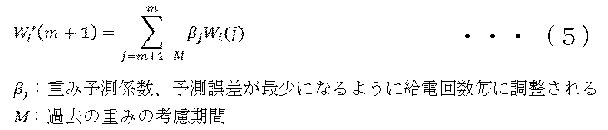
- the prediction weight Wi '(m + 1) is calculated according to the following equation (5).
- the weight prediction coefficient ⁇ j used in the equation (5) is a coefficient optimized for each number of times of power supply such that the prediction error W error calculated according to the following equation (6) is minimized.
- Step S108 In step S108, if it is determined from the power receiving device 51 and the reception signal is not in step S105, the propagation coefficient H i (m + 1) weight based on the W i (m + 1) is not calculated, as shown in Equation (5) prediction Only the weights Wi '(m + 1) are calculated.
- step S109 the storage unit 10 stores the calculated weight Wi (m + 1) and the predicted weight Wi '(m + 1) in the memory. Then, returning to step S101, the signal generator 4 generates the (m + 1) th power supply signal. Then, the above steps are repeatedly executed. However, when it is determined in step S105 that no modulated signal has been received from the power receiving device 51, the weight by which the power supply signal generated by the signal generator 4 is multiplied is replaced with the predicted weight W i ′ (m + 1).
- the power supply signal is adjusted by multiplying the power supply signal generated by the signal generator 4 by a weight, and the adjusted power supply signal is distributed to each antenna element 3A.
- the weight used for the adjustment of the power supply signal is calculated by calculating the propagation coefficient between each antenna element 3A of the power supply device 2 and the antenna 52 of the power reception device 51 according to the equation (2). It is calculated according to equation (3) so as to be conjugate.
- the adjustment is performed for each antenna element 3A. That is, the power supply device 2 adjusts the phase of the power supply signal by multiplying the power supply signal generated by the signal generator 4 by a weight that takes into account the propagation environment between each antenna element 3A and the power reception device 51.
- Each feed radio wave received by the antenna 52 of the power receiving device 51 from each antenna element 3A of the feed device 2 has the same phase. That is, the wireless power supply system 1 can improve power supply efficiency to the power receiving device 51.
- the amplitude of the power supply signal is adjusted by multiplying the power supply signal by the weight in consideration of the propagation environment.
- the supply power P i that is distributed to the i-th antenna element 3A after being adjusted and supplied to the power receiving device 51 is, as shown in Expression (4), the power supply signal P i generated by the signal generator 4. The value is obtained by multiplying the square of the amplitude by the square of the weight.
- the wireless power supply system 1 adjusts the amplitude of the power supply signal transmitted via each antenna element 3A so that the power supplied by the signal generator 4 is supplied to the power receiving device 51 without increasing or decreasing. You will be doing.
- the supply power generated by the signal generator 4 is the upper limit of the limit value defined by the Radio Law as shown in step S101. That is, in the wireless power supply system 1 described above, the maximum supply power that satisfies the provisions of the Radio Law is generated in the signal generator 4, and the maximum supply power is supplied to the power receiving device 51.
- a signal request is made once from the power supply device 2 to the power receiving device 51, and the propagation coefficient is calculated based on the signal received from the power receiving device 51. Therefore, the propagation coefficient is calculated quickly. Therefore, a decrease in the throughput in the power supply device 2 is suppressed, and the power supply time is saved.
- the wireless power supply system 1 As described above, a request for a signal from the power supply device 2 to the power receiving device 51 is performed each time power is supplied. Therefore, in the wireless power supply system 1 as described above, even when the propagation environment between the antenna element 3A of the power supply device 2 and the antenna 52 of the power reception device 51 changes, the change in the propagation environment is prompt.
- the detected radio wave supplied from the antenna element 3A is quickly adjusted. That is, a change in the propagation environment between the power supply device 2 and the antenna 52 of the power reception device 51 is promptly dealt with, and a decrease in the reliability of communication between the power supply device 2 and the power reception device 51 is suppressed.
- processes for adjusting the phase and amplitude of the power supply signal are performed on the power supply device 2 side, not on the power reception device 51.
- the power receiving device 51 side Needs to be transmitted to the power supply device 2 side.
- the power receiving device 51 needs to perform signal processing such as amplification of a transmission signal and removal of noise included in the transmission signal.
- the wireless power supply system 1 as described above As described above, such signal processing becomes unnecessary. Therefore, power consumption on the power receiving device 51 side can be reduced. Therefore, the wireless power supply system 1 as described above is, of course, an effective system when the power receiving device 51 is a device without a battery.
- the communication between the power supply device 2 and the power reception device 51 is interrupted, and a signal from the power reception device 51 in response to a request signal from the power supply device 2 cannot be received, and the propagation coefficient is calculated. Even when the weight cannot be calculated, the weight can be predicted using the weight calculated in the past and stored in the memory. Then, the phase and amplitude of the power supply signal can be adjusted using the predicted weight.
- the weighting prediction coefficient beta j is the prediction error W error is optimized for each feeding times to a minimum. Therefore, even if the propagation coefficient cannot be calculated because the signal from the power receiving device 51 cannot be received in response to the request signal from the power supply device 2, the prediction weight Wi ′ is calculated using the weight prediction coefficient ⁇ j. (M + 1) can be calculated with high accuracy. Even if the propagation environment changes, the accuracy of the prediction weight W i ′ (m + 1) is maintained because the weight prediction coefficient ⁇ j is optimized each time.
- the power reception device 51 modulates the carrier transmitted from the power supply device 2 by opening and closing the switch 54 of the reception circuit 55, and transmits the modulated signal to the power supply device 2.
- a signal can be transmitted to the power supply device 2 without using an oscillator, so that power saving is realized.
- such a signal transmission method can transmit a modulation signal responsive to a request signal to the power supply device 2 even if the power receiving device 51 does not have a battery or has no oscillator. . Therefore, the signal transmission method is a highly convenient signal transmission method.
- the power receiving device 51 when the power receiving device 51 includes various sensor elements that detect a predetermined physical quantity, the power receiving device 51 performs the signal transmission based on the signal corresponding to the predetermined physical quantity detected by the sensor element.
- the opening and closing of the switch 54 of the receiving end circuit 55 it is possible to control the opening and closing of the switch 54 of the receiving end circuit 55 to generate a modulated signal obtained by modulating the carrier received from the power supply device 2. That is, when responding to the power supply device 2, the power receiving device 51 can also transmit information detected by its own sensor together with the response signal. That is, when the power receiving device 51 includes a sensor element, the wireless power supply system 1 described above can save time and effort for transmitting information detected by the sensor to the power supply device 2.
- the power supply apparatus 2 receives from the power receiving apparatus 51 a modulated signal having the same frequency as the carrier frequency. Therefore, when calculating the propagation coefficient, the power supply apparatus 2 does not need to consider the difference between the carrier frequency and the modulation signal frequency. That is, the propagation coefficient is easily estimated.
- the wireless power supply system 1 when estimating the propagation coefficient, the preamble portion of the signal received from the power receiving device 51 is used. Therefore, the wireless power supply system 1 can easily estimate the propagation coefficient without adding a new process to the existing communication protocol.
- the power receiving device 51 may include a battery.
- the battery is an example of the “power storage unit” of the present invention.
- the power receiving device 51 receives a signal request from the power supply device 2 in step S102-4 or step S104, the power reception device 51 generates and transmits a modulated signal obtained by modulating the carrier received from the power supply device 2. Instead, a signal is generated in an oscillator built in its own controller and transmitted to the power supply device 2.
- the propagation coefficient estimation unit 8 replaces the equation (2). in accordance with estimation procedure below may estimate a propagation coefficient H i between the antenna 52 of the array antenna 3 and the power receiving device 51.
- Figure 5 illustrates an example of a flowchart showing the procedure of estimating the propagation coefficient H i schematically. Note that the estimation procedure described below is merely an example, and each processing may be changed as much as possible. Also, in the estimation procedure described below, steps can be omitted, replaced, and added as appropriate according to the embodiment.
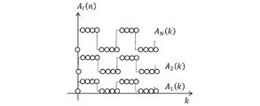
- step S201 the propagation coefficient estimating unit 8 extracts a preamble portion of a signal input from the RF transmitting / receiving circuit 5 of the power supply apparatus 2 to the i-th antenna element 3A. Then, the phase ⁇ i (k) and the amplitude A i (k) of the preamble portion are obtained.
- FIG. 6 schematically illustrates an example of the phase ⁇ i (k) obtained from the preamble portion.
- FIG. 7 schematically illustrates an example of the amplitude A i (k) obtained from the preamble portion.
- i is the index of the antenna element 3A
- k is the sample index of the extracted preamble portion.
- Step S202 the propagation coefficient estimation unit 8, the phase gamma i of the propagation coefficient H i which is expressed by the equation (1) is calculated.
- the phase gamma i of the phase theta i (k) and the propagation coefficient H i it is known that holds the relationship of formula (7) below.
- the propagation coefficient estimating unit 8 can generate a regression line for the phase ⁇ i (k) with respect to k from the data shown in FIG. 6 and calculate the phase ⁇ i using the regression line.
- Step S203 the propagation coefficient estimation unit 8, the amplitude C i of the propagation coefficient H i which is expressed by the equation (1) is calculated.
- the amplitude C i of the amplitude A i (k) and the propagation coefficient H i of preamble it is known that holds the relationship of formula (8) below.
- the propagation coefficient estimation unit 8 by substituting the equation (9) the data shown in Figure 7, it is possible to calculate the amplitude C i.
- the power reception device 51 In such a wireless power supply system, even when power is not supplied from the power supply device 2 to the power reception device 51, the power reception device 51 generates predetermined power such as operating an oscillator, amplifying a signal, and removing noise. Necessary processing can be performed. In addition, communication can be performed between the power supply device 2 and the power receiving device 51. Further, the power supply apparatus 2 receives a response signal having a frequency different from the request signal from the power receiving apparatus 51, but can estimate the propagation coefficient according to the equations (7) and (9). That is, such a wireless power supply system is a highly convenient system that can estimate a propagation coefficient and adjust a power supply signal even for the power receiving device 51 that transmits response signals of various frequencies.
- the antenna 52 of the power receiving device 51 of the wireless power supply system 1 may be an array antenna formed by a plurality of antenna elements 52A.
- FIG. 8 schematically illustrates an example of the outline of the wireless power supply system 1 including the power receiving device 51 including a plurality of antenna elements 52A.
- the RF transmitting / receiving circuit 53 is provided so as to correspond to each of the plurality of antenna elements 52A.
- the propagation coefficient is estimated by the number of combinations of each antenna element 3A of the power feeding device 2 and each antenna element 52A of the power receiving device 51. Then, the feed signal transmitted from each antenna element 3A of the power feeding device 2 to each antenna element 52A of the power receiving device 51 is adjusted based on the propagation coefficient.
- the propagation path (path) of the radio wave between the power supply device 2 and the power receiving device 51 is increased, and the radio wave propagated through a plurality of paths can be concentrated on the power receiving device 51. Therefore, the power supply efficiency to the power receiving device 51 increases.
- the power supply device 2 of the wireless power supply system 1 may supply power to a plurality of power reception devices 51.
- FIG. 9 schematically illustrates an example of the outline of the wireless power supply system 1 that supplies power to the plurality of power receiving devices 51.
- the antenna 52 included in each power receiving device 51 may be a single antenna or an array antenna formed from a plurality of antenna elements as in Modification ⁇ 4.2>.
- the propagation coefficient is estimated by the number of combinations of each antenna element 3A of the power feeding device 2 and each antenna element of each power receiving device 51. Then, a weight is calculated based on the propagation coefficient, and a power supply signal transmitted from each antenna element 3A of the power supply device 2 to each antenna element 52A of each power reception device 51 is adjusted based on the weight.
- the wireless power supply system 1 as described above is a highly convenient system that can supply power to a plurality of power receiving devices 51.
- the RF transmission / reception circuit 5 of the power supply apparatus 2 or the RF transmission / reception circuit 53 of the power receiving apparatus 51 mutual conversion between the RF signal and the BB signal is not performed, and the RF signal is directly converted into an A / D signal by high-speed A / D conversion processing. It may be converted.
- the number of circuits for performing the mutual conversion process between the RF signal and the BB signal is reduced, and the size of the RF transmission / reception circuit can be reduced. Therefore, the power supply device 2 and the power receiving device 51 can be reduced in size. Also, parts costs can be reduced.
- the estimation of the propagation coefficient is performed in the digital circuit, but the estimation of the propagation coefficient may be performed in the analog circuit.
- a propagation coefficient can be directly estimated from an RF signal received by an antenna and used for estimating a propagation coefficient without performing A / D conversion processing. Therefore, the estimation of the propagation coefficient is performed more easily.
- a wireless power supply (2) including an array antenna (3) formed from a plurality of antenna elements (3A), Power supply signal generation means (4) for generating a power supply signal; Propagation coefficient calculation means (8) for calculating respective propagation coefficients between the plurality of antenna elements (3A) and the antenna (52) of the power supply target device (51); Based on the respective propagation coefficients calculated by the propagation coefficient calculation means (8), the phase and the amplitude of the power supply signal generated by the power supply signal generation means (4) are changed to the plurality of antenna elements (3A).
- Weight calculating means (9) for calculating a weight to be adjusted for each; Adjusting the phase and the amplitude of the power supply signal generated by the power supply signal generation means (4) for each of the plurality of antenna elements (3A) based on the weight calculated by the weight calculation means (9); Feed signal distribution means (11) for distributing a feed signal adjusted for each of the plurality of antenna elements (3A) to the plurality of antenna elements (3A); The plurality of antenna elements (3A) forming the array antenna (3) convert the distributed power supply signal into a power supply radio wave and transmit the power supply radio wave to the power supply target device (51). Wireless power supply (2).
- a request signal requesting a response from the power supply target device (51) is transmitted to the power supply target device (51) via the plurality of antenna elements (3A) forming the array antenna (3), and the request signal is transmitted to the power supply target device (51).
- the propagation coefficient calculation means (8) calculates respective propagation coefficients between the plurality of antenna elements (3A) and the antenna (52) of the power supply target device (51) based on the received response signal.
- the wireless power supply device (2) according to the first aspect.
- ⁇ Invention 3> The transmission of the request signal to the power supply target device (51) and the reception of the response signal from the power supply target device (51) to the transmitted request signal are performed when the power supply to the power supply target device (51) is performed. Performed each time, The wireless power supply device (2) according to the second aspect.
- the weight prediction is performed by multiplying a predetermined number of weights stored by the storage means (10) by a weight prediction coefficient corresponding to each of the predetermined number of weights,
- the weight calculation means (9) predicts the weight in addition to calculating the weight based on the propagation coefficient when the response signal is received before the response signal is not received. Update the weight prediction coefficient so that the difference between the weight based on the calculated propagation coefficient and the predicted weight is minimized,
- the wireless power supply device (2) according to the fourth aspect.
- the power supply signal generating means (4) generates a power supply signal to be transmitted to a plurality of power supply target devices (51).
- the wireless power supply device (2) according to any one of Inventions 1 to 5.
- Power supply target device (51) The wireless power supply device (2) according to any one of inventions 1 to 6, wherein the demodulation means (5) demodulates the modulation signal when receiving the modulation signal from the power supply target device (51). ) Further comprising a wireless power supply device (2) further comprising: Wireless power supply system (1).
- the power supply target device (51) further includes a power storage unit.
- ⁇ Invention 9> The antenna (52) included in the power supply target device (51) is formed from a plurality of antenna elements (52A).
Landscapes
- Engineering & Computer Science (AREA)
- Power Engineering (AREA)
- Computer Networks & Wireless Communication (AREA)
- Physics & Mathematics (AREA)
- General Physics & Mathematics (AREA)
- Toxicology (AREA)
- Artificial Intelligence (AREA)
- Computer Vision & Pattern Recognition (AREA)
- General Health & Medical Sciences (AREA)
- Theoretical Computer Science (AREA)
- Electromagnetism (AREA)
- Health & Medical Sciences (AREA)
- Signal Processing (AREA)
- Variable-Direction Aerials And Aerial Arrays (AREA)
- Charge And Discharge Circuits For Batteries Or The Like (AREA)
- Near-Field Transmission Systems (AREA)
Abstract
本発明の無線給電装置は、給電信号を生成する給電信号生成手段と、複数のアンテナ素子と給電対象機器のアンテナとの間の夫々の伝搬係数を計算する伝搬係数計算手段と、夫々の伝搬係数に基づいて、給電信号生成手段によって生成された給電信号の位相及び振幅を、複数のアンテナ素子毎に調整する重みを計算する重み計算手段と、重み計算手段によって計算された重みに基づいて、給電信号生成手段によって生成された給電信号の位相及び振幅を複数のアンテナ素子毎に調整し、調整後の給電信号を複数のアンテナ素子へ配分する給電信号配分手段と、を備え、アレイアンテナを形成する複数のアンテナ素子は、給電信号を給電電波へ変換し、給電対象機器へ給電電波を送信する、無線給電装置である。
Description
本発明は、無線給電装置及び無線給電システムに関する。
RFID(Radio Frequency IDentifier)技術を使用し、RFIDタグとRFIDリーダとの間での無線データ通信や、RFIDリーダからRFIDタグへの無線給電が行われている。また、無線データ通信や無線給電のために、例えば複数のアンテナ素子が規則的に配列されたアレイアンテナをRFIDリーダに設けることが行われている。
アレイアンテナから電波を送信して無線給電を行う場合、アレイアンテナを形成する複数のアンテナ素子から送信される給電電波同士が干渉し、給電対象機器が受け取る供給電力が低下する虞がある。そこで、各アンテナ素子から送信される電波を調整する技術が開示されている(例えば特許文献1-2)。
特許文献1では、アレイアンテナの各アンテナ素子から送信される電波の位相と振幅が、所定の探索アルゴリズムに従い、探索されている。しかしながら、探索アルゴリズムによる探索の実行は、時間を要する。よって、スループットが低下し、給電に時間を要する。また、例えばアレイアンテナと給電対象機器のアンテナとの間の伝搬環境が変化した場合、探索アルゴリズムを使用した方法では、伝搬環境の変化に速やかに対応し、各アンテナ素子から送信される電波を調整し、通信の信頼性を保持することは困難である。
特許文献2では、探索アルゴリズムによる探索は行われず、給電対象機器からの信号を受信し、給電対象機器のアンテナと各アンテナ素子間との経路差を検出し、当該経路差に応じて給電信号の位相を調整している。しかしながら、給電信号の振幅は制御されていない。すなわち、特許文献2に開示の技術を使用して給電を行う場合、給電対象機器へ供給される電力が最大化されず、非効率な給電となる虞がある。
すなわち、本発明者は、従来技術では、アレイアンテナの各アンテナ素子から送信される電波を速やかに、かつ効率的な給電となるように調整することができないことを見出した。
本発明は、一側面では、このような実情を鑑みてなされたものであり、その目的は、アレイアンテナの各アンテナ素子から送信される電波を速やかに、かつ効率的な給電となるように調整することのできる技術を提供することである。
本発明は、上述した課題を解決するために、以下の構成を採用する。
すなわち本発明の一側面に係る無線給電装置は、複数のアンテナ素子から形成されるアレイアンテナを含む無線給電装置であって、給電信号を生成する給電信号生成手段と、前記複数のアンテナ素子と給電対象機器のアンテナとの間の夫々の伝搬係数を計算する伝搬係数計算手段と、前記伝搬係数計算手段によって計算された前記夫々の伝搬係数に基づいて、前記給電信号生成手段によって生成された前記給電信号の位相及び振幅を、前記複数のアンテナ素子毎に調整する重みを計算する重み計算手段と、前記重み計算手段によって計算された前記重みに基づいて、前記給電信号生成手段によって生成された前記給電信号の位相及び振幅を前記複数のアンテナ素子毎に調整し、前記複数のアンテナ素子毎に調整された給電信号を前記複数のアンテナ素子へ配分する給電信号配分手段と、を備え、前記アレイアンテナを形成する前記複数のアンテナ素子は、前記配分された給電信号を給電電波へ変換し、前記給電対象機器へ前記給電電波を送信する、無線給電装置である。
当該構成によれば、無線給電装置の各アンテナ素子と給電対象機器のアンテナとの間の伝搬係数に基づいて重みを計算し、当該重みに基づいて給電信号の位相を調整し、位相が調整された給電信号が各アンテナ素子へ配分される。また、当該位相の調整は、一律に行われるのではなく、複数のアンテナ素子毎に行われる。そして、各アンテナ素子では、当該給電信号が給電電波へ変換され、当該給電電波が給電対象機器へ送信される。すなわち、当該構成は、各アンテナ素子と給電対象機器のアンテナとの間の伝搬環境に応じて給電信号の位相を調整することにより、給電対象機器が各アンテナ素子から受信する各給電電波を同相とすることができる。よって、当該構成は、給電対象機器への給電効率を向上させることができる。
また、当該構成によれば、当該重みに基づいて給電信号の振幅も調整される。すなわち、各アンテナ素子から給電対象機器へ供給される電力は調整される。すなわち、当該構成は、各アンテナ素子と給電対象機器のアンテナとの間の伝搬環境に応じて給電対象機器への供給電力を最大化することができる。
また、当該構成によれば、伝搬係数の計算や重みの計算といった給電信号の位相及び振幅を調整するための処理は、給電対象機器側ではなく、無線給電装置側で実行される。ここで、当該構成とは異なり、伝搬係数の計算や重みの計算といった給電信号の位相及び振幅を調整するための処理が給電対象機器側で行われる場合、給電対象機器側で計算された結果を無線給電装置側へ送信する必要がある。そして、このような送信を行う場合、送信電波のSNR(Signal Noise Ratio)を大きくしておくことが好ましい。よって、給電対象機器側において送信信号の増幅や送信信号に含まれる雑音の除去といった信号処理を行うことが考えられる。そして、これらの信号処理には電力を要する。一方、当該構成によれば、このような信号処理は不要となる。よって、給電対象機器側の消費電力を節減することができる。よって、このような当該構成は、給電対象機器がバッテリーを備えていない機器である場合に有効な構成である。
上記一側面に係る無線給電装置において、前記給電対象機器へ応答を要求する要求信号が、前記アレイアンテナを形成する前記複数のアンテナ素子を介して前記給電対象機器へ送信され、前記要求信号に対する前記給電対象機器からの応答信号が、前記複数のアンテナ素子を介して受信され、前記伝搬係数計算手段は、前記受信した応答信号に基づき、前記複数のアンテナ素子と前記給電対象機器のアンテナとの間の夫々の伝搬係数を計算してもよい。
当該構成によれば、アレイアンテナを形成する各アンテナ素子と給電対象機器のアンテナとの間の電波の送受信を1度行い、当該電波の送受信によって得られた情報に基づいて伝搬係数を計算することができる。よって、手間や時間を要さずに速やかに伝搬係数は計算される。よって、スループットの低下は抑制され、給電時間は削減される。
上記一側面に係る無線給電装置において、前記給電対象機器への前記要求信号の送信、及び前記送信された要求信号に対する前記給電対象機器からの前記応答信号の受信は、前記給電対象機器への給電の都度行われてもよい。
当該構成によれば、アレイアンテナと給電対象機器のアンテナとの間の伝搬係数が変化した場合であっても、各アンテナ素子から送信される給電電波は、当該伝搬係数の変化に応じて速やかに調整される。すなわち、当該構成は、伝搬環境の変化に速やかに対応し、通信の信頼性の低下を抑制することができる。
上記一側面に係る無線給電装置において、前記重み計算手段によって計算された前記重みを順次記憶する記憶手段をさらに備え、前記重み計算手段は、前記応答信号を受信しなかった場合、前記記憶手段によって記憶された所定回数分の重みに基づいて重みを予測し、前記予測した重みで前記伝搬係数に基づいて計算される重みを代替してもよい。
当該構成によれば、応答信号を受信できずに伝搬係数を計算することができない場合であっても、過去に計算し、記憶手段によって記憶された重みに基づき、重みを予測することができる。そして、予測した重みで伝搬係数に基づいて計算する重みを代替することにより、伝搬係数を計算することができない場合であっても、給電信号の位相及び振幅は調整される。
上記一側面に係る無線給電装置において、前記重みの予測は、前記記憶手段によって記憶された所定回数分の重みに、前記所定回数分の重みの夫々に対応する重み予測係数を乗じることによって行われ、前記重み計算手段は、前記応答信号を受信しなかった場合よりも以前の前記応答信号を受信した場合に、前記伝搬係数に基づく重みの計算に加えて前記重みの予測を行い、前記計算した伝搬係数に基づく重みと前記予測した重みとの差が最小となるように前記重み予測係数を更新してもよい。
当該構成によれば、重み予測係数は、伝搬係数に基づき計算した重みと予測した重みとの差が最小となるように最適化される。よって、伝搬係数に基づき重みを計算できない場合であっても、当該重み予測係数を使用して、重みを精度高く予測することができる。また、重み予測係数は、伝搬係数に基づき重みが計算される場合であっても更新されている。すなわち、伝搬環境が変化した場合であっても、重みの予測の精度は保たれることとなる。
上記一側面に係る無線給電装置において、前記給電信号生成手段は、複数の給電対象機器へ送信する給電信号を生成してもよい。
当該構成によれば、複数の給電対象機器へ一度に給電することができる。すなわち、当該無線給電装置は、利便性の高い装置である。
また、本発明の一側面に係る無線給電システムは、アンテナと、前記アンテナを介して系外の機器から電波を受信した場合に、前記受信した電波を変調させた変調信号を生成する変調信号生成手段と、を有する給電対象機器と、上記一側面に係る無線給電装置であって、前記給電対象機器から前記変調信号を受信した場合に、前記変調信号を復調させる復調手段をさらに有する無線給電装置と、を備えてもよい。
当該構成によれば、給電対象機器は、無線給電装置から要求信号を受信した場合、当該要求信号を変調させた変調信号を生成し、当該変調信号を無線給電装置へ送信することができる。換言すれば、給電対象機器は、発振器を使用せずに無線給電装置へ信号を送信することができる。すなわち、当該構成によれば、給電対象機器において発振器を動作させるための電力は必要とされず、省電力化が実現される。また、給電対象機器は、発振器を動作させるための電力を蓄える蓄電手段を有さなくとも無線給電装置へ信号を送信することができ、部品コストの削減も実現される。
また、当該構成によれば、伝搬係数計算手段が、給電対象機器へ送信した要求信号と給電対象機器から受信した変調信号に基づいて伝搬係数を計算する場合であって、当該変調信号が要求信号の周波数を変調させた信号ではない場合、要求信号の周波数と変調信号の周波数に差はないため、当該差を考慮せずに伝搬係数を計算することができる。すなわち、伝搬係数計算手段は、伝搬係数を簡易に計算することができる。
上記一側面に係る無線給電システムにおいて、前記給電対象機器は、蓄電手段をさらに備えてもよい。
当該構成によれば、無線給電装置から給電対象機器への給電の有無に関わらず、所定の電力を要する処理を給電対象機器は行うことができる。所定の電力を要する処理とは、例えば、給電対象機器が発振器を備える場合には当該発振器の動作、信号の増幅、雑音除去といった処理、又は無線給電装置との通信といった処理のことである。
上記一側面に係る無線給電システムにおいて、前記給電対象機器が備える前記アンテナは、複数のアンテナ素子から形成されてもよい。
当該構成によれば、無線給電装置と給電対象機器との間の電波の伝搬経路(パス)が増え、より複数経路で伝搬される電波を給電対象機器に集中させることができる。よって、給電対象機器への給電効率が高まる。
本発明によれば、アレイアンテナの各アンテナ素子から送信される電波を速やかに、かつ効率的な給電となるように調整することのできる技術を提供することができる。
以下、本発明の一側面に係る実施の形態(以下、「本実施形態」とも表記する)を、図面に基づいて説明する。ただし、以下で説明する本実施形態は、あらゆる点において本発明の例示に過ぎない。本発明の範囲を逸脱することなく種々の改良や変形を行うことができることは言うまでもない。つまり、本発明の実施にあたって、実施形態に応じた具体的構成が適宜採用されてもよい。
§1 適用例
図1を用いて、本発明が適用される場面の一例について説明する。図1は、無線給電システム1の概要の一例を模式的に例示する。図1に示されるように、無線給電システム1は、給電装置2と受電装置51を備える。給電装置2は、複数のアンテナ素子3Aから形成されるアレイアンテナ3を備える。一方、受電装置51は、アンテナ52を備える。
図1を用いて、本発明が適用される場面の一例について説明する。図1は、無線給電システム1の概要の一例を模式的に例示する。図1に示されるように、無線給電システム1は、給電装置2と受電装置51を備える。給電装置2は、複数のアンテナ素子3Aから形成されるアレイアンテナ3を備える。一方、受電装置51は、アンテナ52を備える。
また、図1に示されるように、給電装置2は、給電信号を発生させる信号発生器4を備える。また、給電装置2は、アレイアンテナ3のi番目のアンテナ素子3Aと受電装置51のアンテナ52との間の電波の伝搬係数Hiを推定する伝搬係数推定部8を備える。ここで、伝搬係数とは、送受信アンテナ間において電波が伝搬した際の、電波の減衰量および位相変化量を表す係数である。
また、給電装置2は、伝搬係数Hiに基づいて、信号発生器4において発生した給電信号の位相及び振幅を調整する重みWiを計算する重み計算部9を備える。重みWiは、アンテナ素子3Aごとに対応するものであって、伝搬係数Hiとは共役の関係となるように設定される。
また、給電装置2は、重み計算部9において計算された重みを、信号発生器4において発生した給電信号に乗じて給電信号の位相及び振幅を調整し、調整された給電信号を各アンテナ素子3Aへ配分する給電信号配分部11を備える。
そして、給電装置2は、夫々のアンテナ素子3Aが、給電信号配分部11において配分された給電信号を受け取り、当該配分された給電信号を受電装置51のアンテナ52へ送信することにより、受電装置51の給電を行う。
すなわち、上記のような無線給電システム1は、給電装置2が備える夫々のアンテナ素子3Aと受電装置51のアンテナ52との間の伝搬環境に応じて、給電信号の位相及び振幅を適宜調整し、給電効率の向上や供給電力の最大化を行うことができる。
§2 構成例
次に、本実施形態に係る無線給電システムの一例について説明する。図1に示されるように、無線給電システム1は、給電装置2と受電装置51を備える。ここで、無線給電システム1は、本発明の「無線給電システム」の一例である。また、給電装置2は、本発明の「無線給電装置」の一例である。また、受電装置51は、本発明の「給電対象機器」の一例である。給電装置2は、例えばRFIDリーダであり、受電装置51は、例えばRFIDタグである。また、受電装置51には、所定の物理量を検出する各種センサ素子が備わっていてもよい。
次に、本実施形態に係る無線給電システムの一例について説明する。図1に示されるように、無線給電システム1は、給電装置2と受電装置51を備える。ここで、無線給電システム1は、本発明の「無線給電システム」の一例である。また、給電装置2は、本発明の「無線給電装置」の一例である。また、受電装置51は、本発明の「給電対象機器」の一例である。給電装置2は、例えばRFIDリーダであり、受電装置51は、例えばRFIDタグである。また、受電装置51には、所定の物理量を検出する各種センサ素子が備わっていてもよい。
また、給電装置2は、アレイアンテナ3を備える。アレイアンテナ3は、規則的に配列されている複数のアンテナ素子から形成される。また、給電装置2は、給電信号を発生させる信号発生器4を備える。ここで、信号発生器4は、本発明の「給電信号生成手段」の一例である。また、給電装置2は、アレイアンテナ3を介して送受信される信号の処理を行うRF(Radio Frequency)送受信回路5を備える。また、給電装置2は、図示しないが、コントローラと、ROM(Read Only Memory)やRAM(Random Access Memory)といったメモリを備える。
ここで、RF送受信回路5は、例えばアレイアンテナ3を介して送受信されるRF(Radio Frequency)信号とBB(Base Band)信号との相互変換を行うことができる。また、RF送受信回路5は、例えばA/D(Analogue/Digital)変換処理も行う。このような相互変換処理により、給電装置2において低速なデジタル処理を行えるようになる。また、RF送受信回路5は、アレイアンテナ3から送信されたキャリアを変調させた変調信号を受信した場合に、当該変調信号を復調させる処理も行う。また、RF送受信回路5は、本発明の「復調手段」の一例である。
また、図1に示されるように、給電装置2は、アレイアンテナ3のアンテナ素子3Aと受電装置51のアンテナ52との間の電波の伝搬係数を推定する伝搬係数推定部8を備える。伝搬係数推定部8は、本発明の「伝搬係数計算手段」の一例である。ここで、伝搬係数とは、送受信アンテナ間において電波が伝搬した際の電波の減衰量および位相変化量を表す係数である。例えば、i番目のアンテナ素子3Aとアンテナ52との間の伝搬係数Hiは、下記の式(1)のように表される。
Hi=Ciexp(jγi)・・・(1)
ここで、jは虚数単位、γiは伝搬路での電波の位相の回転量を表し、Ciは伝搬路での電波の振幅の減衰量を表す。
また、本実施形態では、上記の伝搬係数Hiは、下記の式(2)に従って推定される。

そして、給電装置2は、式(2)に従って計算される電波の伝搬係数Hiに基づいて、信号発生器4において発生した給電信号の位相及び振幅を調整する重みWiを計算する重み計算部9を備える。ここで、重み計算部9は、本発明の「重み計算手段」の一例である。重みWiは、下記の式(3)に従って、計算される。

ここで、mは給電回数、Nはアンテナ素子3Aの総数を表す。重みWiは、式(3)に示されるように、伝搬係数Hiと共役となるように設定される。また、重みWiは、全ての重みWiの二乗を足し合わせた値が1となるように設定される。
また、給電装置2は、重み計算部9において計算された重みWiをメモリに記憶する記憶部10を備える。ここで、記憶部10は、本発明の「記憶手段」の一例である。そして、給電装置2は、重み計算部9において計算された重みWiを、信号発生器4において発生した給電信号に乗じて給電信号の位相及び振幅を調整し、調整された給電信号を各アンテナ素子3Aへ配分する給電信号配分部11を備える。ここで、給電信号配分部11は、本発明の「給電信号配分手段」の一例である。給電信号配分部11においてi番目のアンテナ素子3Aへ配分され、受電装置51へ供給される供給電力Piは、以下の式(4)のように表される。
給電装置2は、コントローラがメモリに格納された制御プログラムを実行することで、上記のアレイアンテナ3、信号発生器4、RF送受信回路5、伝搬係数推定部8、重み計算部9、記憶部10、給電信号配分部11における処理を実現する。
一方、受電装置51は、アンテナ52を備える。受電装置51は、給電装置2から送信された給電信号を、アンテナ52を介して受信することにより、給電される。また、受電装置51は、RF送受信回路53を備える。
また、受電装置51に設けられるRF送受信回路53は、スイッチ54を有する受端回路55を備え、給電装置2からアンテナ52を介して受信した給電信号の処理や給電装置2へ送信する信号の処理を行う。ここで、受端回路55は、本発明の「変調信号生成手段」の一例である。また、受電装置51は、図示しないが、コントローラ及びメモリを備える。受電装置51のコントローラは、自身の発振器を用いて送信信号を生成しない。コントローラは、代わりに受端回路55のスイッチを制御して受端回路55を開放・短絡させ、給電装置2から受信した受信信号を変調させ、当該変調信号を給電装置2へ送信する。また、コントローラは、受端回路55のスイッチを制御し、受電装置51において生成や検出された信号に基づいて受信電波を変調させ、当該変調信号を送信することもできる。また、受電装置51は、バッテリーを備えていないバッテリーレスの装置である。
§3 動作例
次に、無線給電システム1の動作例を説明する。無線給電システム1は、給電装置2のコントローラ及び受電装置51のコントローラが、夫々の装置のメモリに格納された制御プログラムを実行することにより、以下の動作を実現する。
次に、無線給電システム1の動作例を説明する。無線給電システム1は、給電装置2のコントローラ及び受電装置51のコントローラが、夫々の装置のメモリに格納された制御プログラムを実行することにより、以下の動作を実現する。
図2は、無線給電システム1の動作の概要を示すフローチャートの一例を模式的に例示する。なお、以下で説明する処理手順は一例に過ぎず、各処理は可能な限り変更されてよい。また、以下で説明する処理手順について、実施の形態に応じて、適宜、ステップの省略、置換、及び追加が可能である。
(ステップS101)
図2に示されるように、ステップS101では、信号発生器4においてm回目の給電信号が生成される。給電信号は、その電力が例えば電波法の規定による制限値の上限となるように生成される。
図2に示されるように、ステップS101では、信号発生器4においてm回目の給電信号が生成される。給電信号は、その電力が例えば電波法の規定による制限値の上限となるように生成される。
(ステップS102)
ステップS102では、給電信号配分部11において、信号発生器4において生成された給電信号に、式(3)のように表される重みWi(m)が乗じられることによって、給電信号が調整され、調整された給電信号が各アンテナ素子3Aへ配分される。例えば、給電信号に重みW1(m)が乗じられ、重みW1(m)が乗じられた給電信号が1番目のアンテナ素子3Aへ配分される。次に、給電信号に重みW2(m)が乗じられ、重みW2(m)が乗じられた給電信号が2番目のアンテナ素子3Aへ配分される。このような給電信号の配分は、アンテナ素子3Aの夫々に対応して実行される。
ステップS102では、給電信号配分部11において、信号発生器4において生成された給電信号に、式(3)のように表される重みWi(m)が乗じられることによって、給電信号が調整され、調整された給電信号が各アンテナ素子3Aへ配分される。例えば、給電信号に重みW1(m)が乗じられ、重みW1(m)が乗じられた給電信号が1番目のアンテナ素子3Aへ配分される。次に、給電信号に重みW2(m)が乗じられ、重みW2(m)が乗じられた給電信号が2番目のアンテナ素子3Aへ配分される。このような給電信号の配分は、アンテナ素子3Aの夫々に対応して実行される。
ただし、初回の給電の場合(m=1)、無線給電システム1は、ステップS102において以下のように重みWi(1)を計算する。図3は、初回の給電の場合に重みWi(1)を計算する手順の詳細を示すフローチャートの一例を模式的に例示する。なお、以下で説明する処理手順は一例に過ぎず、各処理は可能な限り変更されてよい。また、以下で説明する処理手順について、実施の形態に応じて、適宜、ステップの省略、置換、及び追加が可能である。
(ステップS102-1)
図3に示されるように、重み計算部9において、重み候補値の中からi番目のアンテナ素子3Aへ給電信号を配分する重みの初期値が選択される。ここで、重み候補値は、予め用意しておかれる。また、重みの初期値の選択は、無作為に選択されてもよいし、所定の方法に従って選択されてもよい。
図3に示されるように、重み計算部9において、重み候補値の中からi番目のアンテナ素子3Aへ給電信号を配分する重みの初期値が選択される。ここで、重み候補値は、予め用意しておかれる。また、重みの初期値の選択は、無作為に選択されてもよいし、所定の方法に従って選択されてもよい。
(ステップS102-2)
ステップS102-2では、信号発生器4において生成された給電信号に重みの初期値が乗じられ、重みの初期値が乗じられた給電信号が各アンテナ素子3Aへ配分される。このような給電信号の配分は、アンテナ素子3Aの夫々に対応して実行される。
ステップS102-2では、信号発生器4において生成された給電信号に重みの初期値が乗じられ、重みの初期値が乗じられた給電信号が各アンテナ素子3Aへ配分される。このような給電信号の配分は、アンテナ素子3Aの夫々に対応して実行される。
(ステップS102-3)
ステップS102-3では、配分された給電信号は、アンテナ素子3Aへ達する前に、RF送受信回路5において高周波へ変換される。そして、各アンテナ素子3Aにおいて高周波から給電電波が生成され、給電電波が受電装置51へ送信されることによって、給電が実行される。
ステップS102-3では、配分された給電信号は、アンテナ素子3Aへ達する前に、RF送受信回路5において高周波へ変換される。そして、各アンテナ素子3Aにおいて高周波から給電電波が生成され、給電電波が受電装置51へ送信されることによって、給電が実行される。
(ステップS102-4)
ステップS102-4では、給電装置2から受電装置51へ信号の要求が実行される。信号の要求は、各アンテナ素子3Aから受電装置51のアンテナ52へキャリアが送信されることによって実現される。
ステップS102-4では、給電装置2から受電装置51へ信号の要求が実行される。信号の要求は、各アンテナ素子3Aから受電装置51のアンテナ52へキャリアが送信されることによって実現される。
受電装置51側では、給電装置2から送信されたキャリアを受信する。受電装置51においては、受端回路55のスイッチ54の開閉が制御され、受端回路55が開放・短絡されることによって、受信したキャリアを変調した変調信号が生成され、当該変調信号が給電装置2へ送信される。図4は、受電装置51が、受信したキャリアを変調させた変調信号を生成し、変調信号を給電装置2へ送信する概要の一例を模式的に例示する。ただし、受電装置51では、キャリアの位相や振幅が変調させられた変調信号が生成されるのであって、キャリアの周波数が変調させられた変調信号は生成されない。
(ステップS102-5)
ステップS102-5では、給電装置2において、ステップS102-4において実行された受電装置51への信号の要求に対し、受電装置51から信号の受信があったか否かの判定が行われる。
ステップS102-5では、給電装置2において、ステップS102-4において実行された受電装置51への信号の要求に対し、受電装置51から信号の受信があったか否かの判定が行われる。
(ステップS102-6)
ステップS102-6では、ステップS102-5において、受電装置51からキャリアの変調信号が受信されたと判定された場合、伝搬係数推定部8において各アンテナ素子3Aと受電装置51のアンテナ52との間の伝搬係数Hiが、式(2)に基づき推定される。ここで、伝搬係数Hiの推定の場合に使用される受電装置51からの受信信号には、受信信号の中のプリアンブル部分が使用される。また、式(2)中の、過去に受電装置51から受信した受信信号のレプリカは、予め生成され、メモリに記憶されている。また、受電装置51から受信した変調信号は、RF送受信回路5においてA/D変換処理やBB信号への変換が行われ、復調される。そして、伝搬係数の推定は、図示しないが給電装置2内に設けられたデジタル回路において実行される。
ステップS102-6では、ステップS102-5において、受電装置51からキャリアの変調信号が受信されたと判定された場合、伝搬係数推定部8において各アンテナ素子3Aと受電装置51のアンテナ52との間の伝搬係数Hiが、式(2)に基づき推定される。ここで、伝搬係数Hiの推定の場合に使用される受電装置51からの受信信号には、受信信号の中のプリアンブル部分が使用される。また、式(2)中の、過去に受電装置51から受信した受信信号のレプリカは、予め生成され、メモリに記憶されている。また、受電装置51から受信した変調信号は、RF送受信回路5においてA/D変換処理やBB信号への変換が行われ、復調される。そして、伝搬係数の推定は、図示しないが給電装置2内に設けられたデジタル回路において実行される。
(ステップS102-7)
ステップS102-7では、重み計算部9において、ステップS102-6において推定された伝搬係数Hiに基づき、重みWi(1)が計算される。伝搬係数から重みを計算する方法は、式(3)に従う。
ステップS102-7では、重み計算部9において、ステップS102-6において推定された伝搬係数Hiに基づき、重みWi(1)が計算される。伝搬係数から重みを計算する方法は、式(3)に従う。
(ステップS102-8)
ステップS102-8では、記憶部10において、計算された重みWi(1)がメモリへ格納される。
ステップS102-8では、記憶部10において、計算された重みWi(1)がメモリへ格納される。
(ステップS102-9)
ステップS102-9では、ステップS102-5において受電装置51からキャリアの変調信号の受信が無いと判定された場合、予め用意した重み候補値が全て選択されたか判定を行う。そして、重み候補値が全て選択されたと判定された場合、給電信号に乗じる重みWi(1)の初期設定を終了する。一方で、重み候補値が全て選択されていないと判定された場合、ステップS102-1へ戻る。
ステップS102-9では、ステップS102-5において受電装置51からキャリアの変調信号の受信が無いと判定された場合、予め用意した重み候補値が全て選択されたか判定を行う。そして、重み候補値が全て選択されたと判定された場合、給電信号に乗じる重みWi(1)の初期設定を終了する。一方で、重み候補値が全て選択されていないと判定された場合、ステップS102-1へ戻る。
上記のステップS102-1からステップS102-9は、ステップS102において、初回の給電時に実行される。
(ステップS103)
ステップS103では、配分された給電信号は、アンテナ素子3Aへ達する前に、RF送受信回路5において高周波へ変換される。そして、各アンテナ素子3Aにおいて高周波から給電電波が生成され、給電電波が受電装置51へ送信されることによって、給電が実行される。i番目のアンテナ素子3Aから受電装置51へ供給される電力Piは、式(4)のように表される。
ステップS103では、配分された給電信号は、アンテナ素子3Aへ達する前に、RF送受信回路5において高周波へ変換される。そして、各アンテナ素子3Aにおいて高周波から給電電波が生成され、給電電波が受電装置51へ送信されることによって、給電が実行される。i番目のアンテナ素子3Aから受電装置51へ供給される電力Piは、式(4)のように表される。
(ステップS104)
また、ステップS104では、給電装置2から受電装置51へ信号の要求が実行される。信号の要求は、各アンテナ素子3Aからキャリアが受電装置51のアンテナ52へ送信されることによって実現される。
また、ステップS104では、給電装置2から受電装置51へ信号の要求が実行される。信号の要求は、各アンテナ素子3Aからキャリアが受電装置51のアンテナ52へ送信されることによって実現される。
受電装置51側では、給電装置2から送信されたキャリアを受信する。受電装置51においては、受端回路55のスイッチ54の開閉が制御され、受端回路55が開放・短絡されることによって、受信したキャリアを変調した変調信号が生成され、当該変調信号が給電装置2へ送信される。ただし、受電装置51において、キャリアの位相や振幅が変調させられた変調信号が生成されるのであって、キャリアの周波数が変調させられた変調信号は生成されない。
(ステップS105)
ステップS105では、給電装置2において、ステップS104において実行された受電装置51への信号の要求に対し、受電装置51から信号の受信があったか否かの判定が行われる。
ステップS105では、給電装置2において、ステップS104において実行された受電装置51への信号の要求に対し、受電装置51から信号の受信があったか否かの判定が行われる。
(ステップS106)
ステップS106では、ステップS105において、受電装置51からキャリアの変調信号が受信されたと判定された場合、伝搬係数推定部8において各アンテナ素子3Aと受電装置51のアンテナ52との間の伝搬係数Hi(m+1)が、式(2)に基づき推定される。ここで、伝搬係数Hiの推定の場合に使用される受電装置51からの受信信号には、受信信号の中のプリアンブル部分が使用される。また、式(2)中の過去に受電装置51から受信した受信信号のレプリカは、予め生成され、メモリに記憶されている。また、受電装置51から受信した変調信号は、RF送受信回路5においてA/D変換処理やBB信号への変換が行われ、復調される。そして、伝搬係数の推定は、図示しないが給電装置2内に設けられたデジタル回路において実行される。
ステップS106では、ステップS105において、受電装置51からキャリアの変調信号が受信されたと判定された場合、伝搬係数推定部8において各アンテナ素子3Aと受電装置51のアンテナ52との間の伝搬係数Hi(m+1)が、式(2)に基づき推定される。ここで、伝搬係数Hiの推定の場合に使用される受電装置51からの受信信号には、受信信号の中のプリアンブル部分が使用される。また、式(2)中の過去に受電装置51から受信した受信信号のレプリカは、予め生成され、メモリに記憶されている。また、受電装置51から受信した変調信号は、RF送受信回路5においてA/D変換処理やBB信号への変換が行われ、復調される。そして、伝搬係数の推定は、図示しないが給電装置2内に設けられたデジタル回路において実行される。
(ステップS107)
ステップS107では、重み計算部9において、ステップS106において推定された伝搬係数Hi(m+1)に基づき、重みWi(m+1)が計算される。伝搬係数から重みを計算する方法は、式(3)に従う。
ステップS107では、重み計算部9において、ステップS106において推定された伝搬係数Hi(m+1)に基づき、重みWi(m+1)が計算される。伝搬係数から重みを計算する方法は、式(3)に従う。
また、ステップS107では、重み計算部9において、ステップS106において推定された伝搬係数Hi(m+1)を使用せず、過去に推定され、メモリに記憶された重みWiに基づき、予測重みWi’(m+1)が計算される。予測重みWi’(m+1)は下記の式(5)に従い、計算される。
ここで、式(5)で使用される重み予測係数βjは、以下の式(6)に従い計算される予測誤差Werrorが最小となるよう給電回数毎に最適化された係数である。

(ステップS108)
ステップS108では、ステップS105において受電装置51から信号の受信が無いと判定された場合、伝搬係数Hi(m+1)に基づく重みWi(m+1)は計算されず、式(5)に示される予測重みWi’(m+1)のみが計算される。
ステップS108では、ステップS105において受電装置51から信号の受信が無いと判定された場合、伝搬係数Hi(m+1)に基づく重みWi(m+1)は計算されず、式(5)に示される予測重みWi’(m+1)のみが計算される。
(ステップS109)
ステップS109では、記憶部10において、計算された重みWi(m+1)及び予測重みWi’(m+1)がメモリへ格納される。そして、ステップS101に戻り、信号発生器4においてm+1回目の給電信号が生成される。そして、上記のステップは繰り返し実行される。ただし、ステップS105において受電装置51から変調信号の受信が無いと判定された場合、信号発生器4において生成された給電信号に乗じる重みを、予測重みWi’(m+1)で代替する。
ステップS109では、記憶部10において、計算された重みWi(m+1)及び予測重みWi’(m+1)がメモリへ格納される。そして、ステップS101に戻り、信号発生器4においてm+1回目の給電信号が生成される。そして、上記のステップは繰り返し実行される。ただし、ステップS105において受電装置51から変調信号の受信が無いと判定された場合、信号発生器4において生成された給電信号に乗じる重みを、予測重みWi’(m+1)で代替する。
[作用・効果]
上記のような無線給電システム1であれば、信号発生器4において生成された給電信号に重みを乗じることによって、給電信号が調整され、調整された給電信号が各アンテナ素子3Aへ配分される。また、当該給電信号の調整に使用される重みは、給電装置2の各アンテナ素子3Aと受電装置51のアンテナ52との間の伝搬係数が式(2)に従って計算され、計算された伝搬係数と共役になるように式(3)に従って計算されている。また、当該調整は、アンテナ素子3A毎に行われる。すなわち、給電装置2が、各アンテナ素子3Aと受電装置51との間の伝搬環境を考慮した重みを、信号発生器4において生成された給電信号へ乗じて給電信号の位相を調整することにより、受電装置51のアンテナ52が給電装置2の各アンテナ素子3Aから受信する各給電電波は同相となる。すなわち、無線給電システム1は、受電装置51への給電効率を向上させることができる。
上記のような無線給電システム1であれば、信号発生器4において生成された給電信号に重みを乗じることによって、給電信号が調整され、調整された給電信号が各アンテナ素子3Aへ配分される。また、当該給電信号の調整に使用される重みは、給電装置2の各アンテナ素子3Aと受電装置51のアンテナ52との間の伝搬係数が式(2)に従って計算され、計算された伝搬係数と共役になるように式(3)に従って計算されている。また、当該調整は、アンテナ素子3A毎に行われる。すなわち、給電装置2が、各アンテナ素子3Aと受電装置51との間の伝搬環境を考慮した重みを、信号発生器4において生成された給電信号へ乗じて給電信号の位相を調整することにより、受電装置51のアンテナ52が給電装置2の各アンテナ素子3Aから受信する各給電電波は同相となる。すなわち、無線給電システム1は、受電装置51への給電効率を向上させることができる。
また、上記のような無線給電システム1によれば、伝搬環境を考慮した重みを給電信号に乗じることによって、給電信号の振幅も調整される。また、調整された後にi番目のアンテナ素子3Aへ配分され、受電装置51へ供給される供給電力Piは、式(4)に示されるように、信号発生器4において生成された給電信号の振幅の2乗に、重みの2乗を乗じた値となる。ここで、式(4)の両辺の和をとり、各アンテナ素子3Aから受電装置51へ供給される供給電力の総和を求めると、重みWiの2乗和は1であるから(式(3)より)、供給電力の総和は、信号発生器4において生成された給電信号の振幅の2乗に等しいこととなる。すなわち、無線給電システム1は、信号発生器4において生成された供給電力が、増加や減少なくそのまま受電装置51へ供給されるよう、各アンテナ素子3Aを介して送信される給電信号の振幅を調整していることとなる。ところで、信号発生器4において生成される供給電力は、ステップS101に示されるように、電波法の規定による制限値の上限となっている。すなわち、上記の無線給電システム1は、電波法の規定を満たす最大の供給電力が信号発生器4において生成され、その最大の供給電力を受電装置51へ供給していることとなる。
また、上記のような無線給電システム1であれば、給電装置2から受電装置51へ1度信号要求をし、受電装置51から受信した信号に基づいて伝搬係数が計算されている。よって伝搬係数は、速やかに計算される。よって、給電装置2におけるスループットの低下は抑制され、給電時間は節減される。
また、上記のような無線給電システム1は、給電装置2から受電装置51へ信号の要求が、給電の都度行われている。よって、上記のような無線給電システム1であれば、給電装置2のアンテナ素子3Aと受電装置51のアンテナ52との間の伝搬環境が変化した場合であっても、伝搬環境の変化は速やかに検知され、アンテナ素子3Aから給電される給電電波は速やかに調整される。すなわち、給電装置2と受電装置51のアンテナ52との間の伝搬環境の変化に速やかに対応し、給電装置2と受電装置51との間の通信の信頼性の低下は抑制される。
また、上記のような無線給電システム1は、伝搬係数の計算や重みの計算といった給電信号の位相及び振幅を調整するための処理は、受電装置51ではなく、給電装置2側で実行されている。ここで、上記のような無線給電システム1とは異なり、伝搬係数の計算や重みの計算といった給電信号の位相及び振幅を調整するための処理が受電装置51側で行われる場合、受電装置51側で計算された結果を給電装置2側へ送信する必要がある。そして、このような送信を行う場合、送信電波のSNRを大きくしておくことが好ましい。よって、受電装置51側において送信信号の増幅や送信信号に含まれる雑音の除去といった信号処理を行う必要がある。そして、これらの信号処理には電力を要する。一方、上記のような無線給電システム1によれば、このような信号処理は不要となる。よって、受電装置51側の消費電力を節減することができる。よって、上記のような無線給電システム1は、受電装置51がバッテリーを備えていない機器である場合に有効なシステムであることは勿論のことである。
また、上記のような無線給電システム1であれば、給電装置2と受電装置51との通信が途絶え、給電装置2からの要求信号に対する受電装置51からの信号が受信できずに伝搬係数を計算することができない場合であっても、過去に計算され、メモリに記憶された重みを使用して重みの予測を行うことができる。そして、予測した重みを使用し、給電信号の位相及び振幅を調整することができる。
また、上記のような無線給電システム1であれば、重み予測係数βjは、予測誤差Werrorが最小となるよう給電回数毎に最適化されている。よって、給電装置2からの要求信号に対する受電装置51からの信号が受信できずに伝搬係数を計算することができない場合であっても、重み予測係数βjを使用して、予測重みWi’(m+1)を精度高く計算することができる。また、伝搬環境が変化した場合であっても、重み予測係数βjは毎回最適化されているため、予測重みWi’(m+1)の精度は保たれることとなる。
また、受電装置51は、給電装置2からの信号要求に対し、給電装置2から送信されたキャリアを受端回路55のスイッチ54の開閉により変調させ、当該変調信号を給電装置2へ送信している。このような信号送信方法は、発振器を使用せず、給電装置2へ信号を送信することができるため、省電力化が実現される。また、このような信号送信方法は、受電装置51がバッテリーを有していない装置又は発振器を備えていない装置であっても、要求信号に応答する変調信号を給電装置2へ送信することができる。よって、当該信号送信方法は、利便性の高い信号送信方法である。
また、上記のような信号送信方法は、受電装置51が所定の物理量を検出する各種センサ素子を備えている場合、受電装置51は、センサ素子によって検出された所定の物理量に対応する信号に基づいて、受端回路55のスイッチ54の開閉を制御し、給電装置2から受信したキャリアを変調させた変調信号を生成することができる。すなわち、受電装置51は、給電装置2へ応答する場合に、自身が備えるセンサによって検出された情報も応答信号と共に送信することができる。すなわち、上記のような無線給電システム1は、受電装置51がセンサ素子を備える場合に、センサによって検出された情報を給電装置2へ送信するための手間や無駄を省くことができるシステムである。
また、給電装置2は、キャリアの周波数と同じ周波数の変調信号を受電装置51から受信することとなる。よって、給電装置2は、伝搬係数を計算する場合に、キャリアの周波数と変調信号の周波数との差を考慮せずに済む。すなわち、伝搬係数は、簡易に推定される。
また、上記のような無線給電システム1は、伝搬係数を推定する場合に、受電装置51からの受信信号のプリアンブル部分が使用されている。よって、無線給電システム1は、既存の通信プロトコルに新たな処理を加えることなく、伝搬係数を簡易に推定することができる。
§4 変形例
以上、本発明の実施の形態を詳細に説明してきたが、前述までの説明はあらゆる点において本発明の例示に過ぎない。本発明の範囲を逸脱することなく種々の改良や変形を行うことができることは言うまでもない。例えば、以下のような変更が可能である。なお、以下では、上記実施形態と同様の構成要素に関しては同様の符号を用い、上記実施形態と同様の点については、適宜説明を省略した。以下の変形例は適宜組み合わせ可能である。
以上、本発明の実施の形態を詳細に説明してきたが、前述までの説明はあらゆる点において本発明の例示に過ぎない。本発明の範囲を逸脱することなく種々の改良や変形を行うことができることは言うまでもない。例えば、以下のような変更が可能である。なお、以下では、上記実施形態と同様の構成要素に関しては同様の符号を用い、上記実施形態と同様の点については、適宜説明を省略した。以下の変形例は適宜組み合わせ可能である。
<4.1>
上記の無線給電システム1において受電装置51は、バッテリーを備えてもよい。ここで、バッテリーは、本発明の「蓄電手段」の一例である。そして、ステップS102-4やステップS104において、受電装置51が給電装置2からの信号要求を受信した場合、受電装置51は、給電装置2から受信したキャリアを変調させた変調信号を生成して送信するのではなく、自身のコントローラが内蔵する発振器において信号を生成し、給電装置2へ送信する。ここで、給電装置2の信号発生器4の発振器と受電装置51の発振器が異なる周波数の信号を生成する場合、給電装置2から受電装置51へ送信された要求信号の電波の周波数と、要求信号に応じて受電装置51から給電装置2へ送信された電波の周波数とは異なることとなる。そして、給電装置2から受電装置51へ送信された電波の周波数と、受電装置51から給電装置2へ送信された電波の周波数とが異なる場合、伝搬係数推定部8は、式(2)の代わりに下記の推定手順に従い、アレイアンテナ3と受電装置51のアンテナ52との間の伝搬係数Hiを推定してもよい。図5は、伝搬係数Hiの推定手順を示すフローチャートの一例を模式的に例示する。なお、以下で説明する推定手順は一例に過ぎず、各処理は可能な限り変更されてよい。また、以下で説明する推定手順について、実施の形態に応じて、適宜、ステップの省略、置換、及び追加が可能である。
上記の無線給電システム1において受電装置51は、バッテリーを備えてもよい。ここで、バッテリーは、本発明の「蓄電手段」の一例である。そして、ステップS102-4やステップS104において、受電装置51が給電装置2からの信号要求を受信した場合、受電装置51は、給電装置2から受信したキャリアを変調させた変調信号を生成して送信するのではなく、自身のコントローラが内蔵する発振器において信号を生成し、給電装置2へ送信する。ここで、給電装置2の信号発生器4の発振器と受電装置51の発振器が異なる周波数の信号を生成する場合、給電装置2から受電装置51へ送信された要求信号の電波の周波数と、要求信号に応じて受電装置51から給電装置2へ送信された電波の周波数とは異なることとなる。そして、給電装置2から受電装置51へ送信された電波の周波数と、受電装置51から給電装置2へ送信された電波の周波数とが異なる場合、伝搬係数推定部8は、式(2)の代わりに下記の推定手順に従い、アレイアンテナ3と受電装置51のアンテナ52との間の伝搬係数Hiを推定してもよい。図5は、伝搬係数Hiの推定手順を示すフローチャートの一例を模式的に例示する。なお、以下で説明する推定手順は一例に過ぎず、各処理は可能な限り変更されてよい。また、以下で説明する推定手順について、実施の形態に応じて、適宜、ステップの省略、置換、及び追加が可能である。
(ステップS201)
ステップS201では、伝搬係数推定部8において、給電装置2のRF送受信回路5からi番目のアンテナ素子3Aへ入力される信号のプリアンブル部分が抽出される。そして、プリアンブル部分の位相θi(k)と振幅Ai(k)が求められる。図6は、プリアンブル部分から求められた位相θi(k)の一例を模式的に例示する。また、図7は、プリアンブル部分から求められた振幅Ai(k)の一例を模式的に例示する。ここで、iはアンテナ素子3Aのインデックス、kは抽出したプリアンブル部分のサンプルインデックスである。
ステップS201では、伝搬係数推定部8において、給電装置2のRF送受信回路5からi番目のアンテナ素子3Aへ入力される信号のプリアンブル部分が抽出される。そして、プリアンブル部分の位相θi(k)と振幅Ai(k)が求められる。図6は、プリアンブル部分から求められた位相θi(k)の一例を模式的に例示する。また、図7は、プリアンブル部分から求められた振幅Ai(k)の一例を模式的に例示する。ここで、iはアンテナ素子3Aのインデックス、kは抽出したプリアンブル部分のサンプルインデックスである。
(ステップS202)
ステップS202では、伝搬係数推定部8において、式(1)のように表される伝搬係数Hiの位相γiが計算される。ここで、位相θi(k)と伝搬係数Hiの位相γiとの間には、以下の式(7)の関係が成り立つことが知られている。
ステップS202では、伝搬係数推定部8において、式(1)のように表される伝搬係数Hiの位相γiが計算される。ここで、位相θi(k)と伝搬係数Hiの位相γiとの間には、以下の式(7)の関係が成り立つことが知られている。
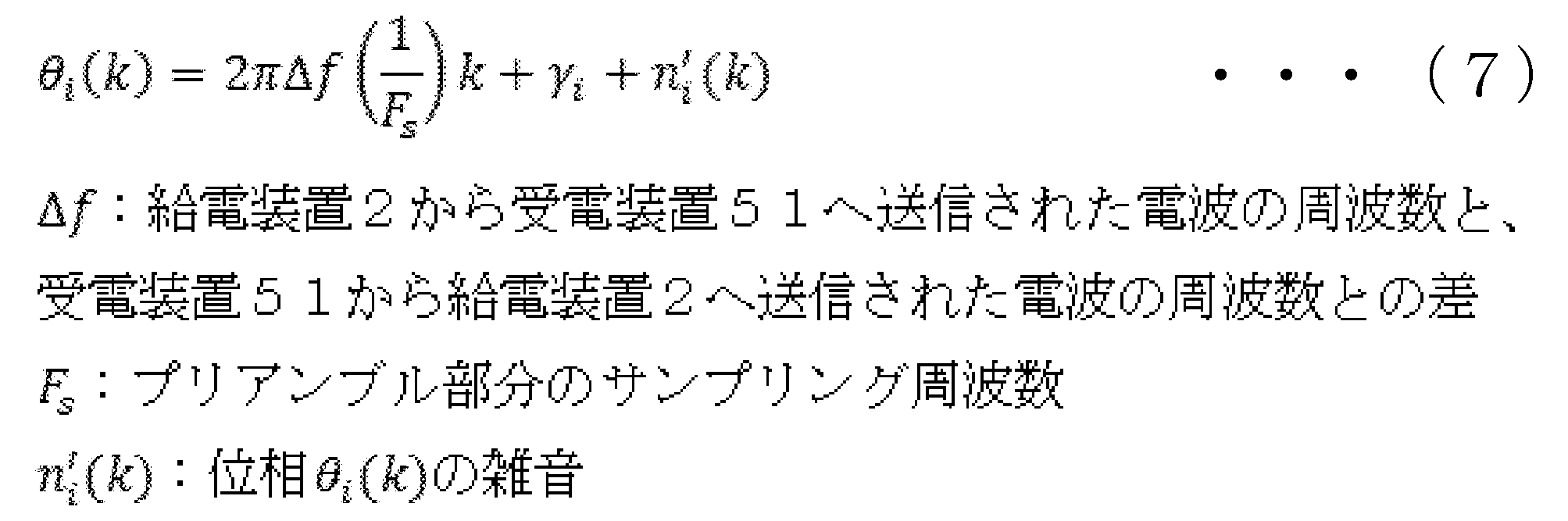
よって、伝搬係数推定部8は、図6に示されるデータから、位相θi(k)のkに関する回帰直線を生成し、当該回帰直線を使用して位相γiを演算することができる。
(ステップS203)
ステップS203では、伝搬係数推定部8において、式(1)のように表される伝搬係数Hiの振幅Ciが計算される。ここで、プリアンブル部分の振幅Ai(k)と伝搬係数Hiの振幅Ciとの間には、以下の式(8)の関係が成り立つことが知られている。
ステップS203では、伝搬係数推定部8において、式(1)のように表される伝搬係数Hiの振幅Ciが計算される。ここで、プリアンブル部分の振幅Ai(k)と伝搬係数Hiの振幅Ciとの間には、以下の式(8)の関係が成り立つことが知られている。

また、上記の雑音が、例えば0を中心として一様にばらつく雑音とみなされる場合、振幅Ciは下記の式(9)に従い、簡易に計算される。

よって、伝搬係数推定部8は、図7に示されるデータを式(9)に代入することにより、振幅Ciを演算することができる。
[作用・効果]
このような無線給電システムであれば、給電装置2から受電装置51へ給電されない場合であっても、受電装置51は、発振器を動作させることや、信号の増幅、雑音除去といった、所定の電力を要する処理を行うことができる。また、給電装置2と受電装置51へとの間で通信を行うこともできる。また、給電装置2は、受電装置51から要求信号とは異なる周波数の応答信号を受信することとなるが、式(7)、式(9)に従い、伝搬係数を推定することができる。すなわち、このような無線給電システムは、様々な周波数の応答信号を発信する受電装置51に対しても、伝搬係数を推定し、給電信号を調整することのできる利便性の高いシステムである。
このような無線給電システムであれば、給電装置2から受電装置51へ給電されない場合であっても、受電装置51は、発振器を動作させることや、信号の増幅、雑音除去といった、所定の電力を要する処理を行うことができる。また、給電装置2と受電装置51へとの間で通信を行うこともできる。また、給電装置2は、受電装置51から要求信号とは異なる周波数の応答信号を受信することとなるが、式(7)、式(9)に従い、伝搬係数を推定することができる。すなわち、このような無線給電システムは、様々な周波数の応答信号を発信する受電装置51に対しても、伝搬係数を推定し、給電信号を調整することのできる利便性の高いシステムである。
<4.2>
また、無線給電システム1の受電装置51のアンテナ52は、複数のアンテナ素子52Aから形成されるアレイアンテナでもよい。図8は、複数のアンテナ素子52Aを備える受電装置51を含む無線給電システム1の概要の一例を模式的に例示する。図8に示されるような受電装置51の場合、RF送受信回路53は、複数のアンテナ素子52A毎に対応するよう設けられる。また、図8に示される無線給電システムでは、伝搬係数は、給電装置2の各アンテナ素子3Aと、受電装置51の各アンテナ素子52Aとの組み合わせの数だけ推定されることとなる。そして、当該伝搬係数に基づき、給電装置2の各アンテナ素子3Aから受電装置51の各アンテナ素子52Aへ送信される給電信号は、各々調整される。
また、無線給電システム1の受電装置51のアンテナ52は、複数のアンテナ素子52Aから形成されるアレイアンテナでもよい。図8は、複数のアンテナ素子52Aを備える受電装置51を含む無線給電システム1の概要の一例を模式的に例示する。図8に示されるような受電装置51の場合、RF送受信回路53は、複数のアンテナ素子52A毎に対応するよう設けられる。また、図8に示される無線給電システムでは、伝搬係数は、給電装置2の各アンテナ素子3Aと、受電装置51の各アンテナ素子52Aとの組み合わせの数だけ推定されることとなる。そして、当該伝搬係数に基づき、給電装置2の各アンテナ素子3Aから受電装置51の各アンテナ素子52Aへ送信される給電信号は、各々調整される。
[作用・効果]
上記のような無線給電システム1は、給電装置2と受電装置51との間の電波の伝搬経路(パス)が増え、より複数経路で伝搬される電波を受電装置51に集中させることができる。よって、受電装置51への給電効率が高まる。
上記のような無線給電システム1は、給電装置2と受電装置51との間の電波の伝搬経路(パス)が増え、より複数経路で伝搬される電波を受電装置51に集中させることができる。よって、受電装置51への給電効率が高まる。
<4.3>
また、無線給電システム1の給電装置2は、複数の受電装置51へ給電してもよい。図9は、複数の受電装置51へ給電する無線給電システム1の概要の一例を模式的に例示する。ここで、各受電装置51が備えるアンテナ52は、単数であっても変形例<4.2>のように複数のアンテナ素子から形成されるアレイアンテナであってもよい。また、図9に示される無線給電システムでは、伝搬係数は、給電装置2の各アンテナ素子3Aと、各受電装置51の各アンテナ素子との組み合わせの数だけ推定されることとなる。そして、当該伝搬係数に基づいて重みが計算され、給電装置2の各アンテナ素子3Aから各受電装置51の各アンテナ素子52Aへ送信される給電信号は、当該重みに基づいて各々調整される。
また、無線給電システム1の給電装置2は、複数の受電装置51へ給電してもよい。図9は、複数の受電装置51へ給電する無線給電システム1の概要の一例を模式的に例示する。ここで、各受電装置51が備えるアンテナ52は、単数であっても変形例<4.2>のように複数のアンテナ素子から形成されるアレイアンテナであってもよい。また、図9に示される無線給電システムでは、伝搬係数は、給電装置2の各アンテナ素子3Aと、各受電装置51の各アンテナ素子との組み合わせの数だけ推定されることとなる。そして、当該伝搬係数に基づいて重みが計算され、給電装置2の各アンテナ素子3Aから各受電装置51の各アンテナ素子52Aへ送信される給電信号は、当該重みに基づいて各々調整される。
[作用・効果]
上記のような無線給電システム1は、複数の受電装置51へ給電することのできる利便性の高いシステムである。
上記のような無線給電システム1は、複数の受電装置51へ給電することのできる利便性の高いシステムである。
また、上記の給電装置2のRF送受信回路5又は受電装置51のRF送受信回路53において、RF信号とBB信号の相互変換が行われず、高速なA/D変換処理によってRF信号が直接A/D変換されてもよい。このような無線給電システム1であれば、RF信号とBB信号との相互変換処理が実行される回路が削減され、RF送受信回路の小型化が可能となる。よって、給電装置2や受電装置51の小型化が可能なる。また、部品コストも削減することができる。
また、上記の無線給電システム1の給電装置2において、伝搬係数の推定はデジタル回路において実行されているが、伝搬係数の推定は、アナログ回路において実行されてもよい。このような無線給電システム1であれば、アンテナにおいて受信し、伝搬係数の推定に使用されるRF信号から、A/D変換処理されずに伝搬係数を直接推定することができる。よって、伝搬係数の推定はより簡易に実行される。
以上で開示した実施形態や変形例はそれぞれ組み合わせる事ができる。
なお、以下には本発明の構成要件と実施例の構成とを対比可能とするために、本発明の構成要件を図面の符号付きで記載しておく。
<発明1>
複数のアンテナ素子(3A)から形成されるアレイアンテナ(3)を含む無線給電装置(2)であって、
給電信号を生成する給電信号生成手段(4)と、
前記複数のアンテナ素子(3A)と給電対象機器(51)のアンテナ(52)との間の夫々の伝搬係数を計算する伝搬係数計算手段(8)と、
前記伝搬係数計算手段(8)によって計算された前記夫々の伝搬係数に基づいて、前記給電信号生成手段(4)によって生成された前記給電信号の位相及び振幅を、前記複数のアンテナ素子(3A)毎に調整する重みを計算する重み計算手段(9)と、
前記重み計算手段(9)によって計算された前記重みに基づいて、前記給電信号生成手段(4)によって生成された前記給電信号の位相及び振幅を前記複数のアンテナ素子(3A)毎に調整し、前記複数のアンテナ素子(3A)毎に調整された給電信号を前記複数のアンテナ素子(3A)へ配分する給電信号配分手段(11)と、を備え、
前記アレイアンテナ(3)を形成する前記複数のアンテナ素子(3A)は、前記配分された給電信号を給電電波へ変換し、前記給電対象機器(51)へ前記給電電波を送信する、
無線給電装置(2)。
<発明2>
前記給電対象機器(51)へ応答を要求する要求信号が、前記アレイアンテナ(3)を形成する前記複数のアンテナ素子(3A)を介して前記給電対象機器(51)へ送信され、前記要求信号に対する前記給電対象機器(51)からの応答信号が、前記複数のアンテナ素子(3A)を介して受信され、
前記伝搬係数計算手段(8)は、前記受信した応答信号に基づき、前記複数のアンテナ素子(3A)と前記給電対象機器(51)のアンテナ(52)との間の夫々の伝搬係数を計算する、
発明1に記載の無線給電装置(2)。
<発明3>
前記給電対象機器(51)への前記要求信号の送信、及び前記送信された要求信号に対する前記給電対象機器(51)からの前記応答信号の受信は、前記給電対象機器(51)への給電の都度行われる、
発明2に記載の無線給電装置(2)。
<発明4>
前記重み計算手段(9)によって計算された前記重みを順次記憶する記憶手段(10)をさらに備え、
前記重み計算手段(9)は、前記応答信号を受信しなかった場合、前記記憶手段(10)によって記憶された所定回数分の重みに基づいて重みを予測し、前記予測した重みで前記伝搬係数に基づいて計算される重みを代替する、
発明2又は3に記載の無線給電装置(2)。
<発明5>
前記重みの予測は、前記記憶手段(10)によって記憶された所定回数分の重みに、前記所定回数分の重みの夫々に対応する重み予測係数を乗じることによって行われ、
前記重み計算手段(9)は、前記応答信号を受信しなかった場合よりも以前の前記応答信号を受信した場合に、前記伝搬係数に基づく重みの計算に加えて前記重みの予測を行い、前記計算した伝搬係数に基づく重みと前記予測した重みとの差が最小となるように前記重み予測係数を更新する、
発明4に記載の無線給電装置(2)。
<発明6>
前記給電信号生成手段(4)は、複数の給電対象機器(51)へ送信する給電信号を生成する、
発明1から5のうち何れか一つに記載の無線給電装置(2)。
<発明7>
アンテナ(52)と、前記アンテナ(52)を介して系外の機器から電波を受信した場合に、前記受信した電波を変調させた変調信号を生成する変調信号生成手段(55)と、を有する給電対象機器(51)と、
発明1から6のうち何れか1つに記載の無線給電装置(2)であって、前記給電対象機器(51)から前記変調信号を受信した場合に、前記変調信号を復調させる復調手段(5)をさらに有する無線給電装置(2)と、を備える、
無線給電システム(1)。
<発明8>
前記給電対象機器(51)は、蓄電手段をさらに備える、
発明7に記載の無線給電システム(1)。
<発明9>
前記給電対象機器(51)が備える前記アンテナ(52)は、複数のアンテナ素子(52A)から形成される、
発明7又は8に記載の無線給電システム(1)。
<発明1>
複数のアンテナ素子(3A)から形成されるアレイアンテナ(3)を含む無線給電装置(2)であって、
給電信号を生成する給電信号生成手段(4)と、
前記複数のアンテナ素子(3A)と給電対象機器(51)のアンテナ(52)との間の夫々の伝搬係数を計算する伝搬係数計算手段(8)と、
前記伝搬係数計算手段(8)によって計算された前記夫々の伝搬係数に基づいて、前記給電信号生成手段(4)によって生成された前記給電信号の位相及び振幅を、前記複数のアンテナ素子(3A)毎に調整する重みを計算する重み計算手段(9)と、
前記重み計算手段(9)によって計算された前記重みに基づいて、前記給電信号生成手段(4)によって生成された前記給電信号の位相及び振幅を前記複数のアンテナ素子(3A)毎に調整し、前記複数のアンテナ素子(3A)毎に調整された給電信号を前記複数のアンテナ素子(3A)へ配分する給電信号配分手段(11)と、を備え、
前記アレイアンテナ(3)を形成する前記複数のアンテナ素子(3A)は、前記配分された給電信号を給電電波へ変換し、前記給電対象機器(51)へ前記給電電波を送信する、
無線給電装置(2)。
<発明2>
前記給電対象機器(51)へ応答を要求する要求信号が、前記アレイアンテナ(3)を形成する前記複数のアンテナ素子(3A)を介して前記給電対象機器(51)へ送信され、前記要求信号に対する前記給電対象機器(51)からの応答信号が、前記複数のアンテナ素子(3A)を介して受信され、
前記伝搬係数計算手段(8)は、前記受信した応答信号に基づき、前記複数のアンテナ素子(3A)と前記給電対象機器(51)のアンテナ(52)との間の夫々の伝搬係数を計算する、
発明1に記載の無線給電装置(2)。
<発明3>
前記給電対象機器(51)への前記要求信号の送信、及び前記送信された要求信号に対する前記給電対象機器(51)からの前記応答信号の受信は、前記給電対象機器(51)への給電の都度行われる、
発明2に記載の無線給電装置(2)。
<発明4>
前記重み計算手段(9)によって計算された前記重みを順次記憶する記憶手段(10)をさらに備え、
前記重み計算手段(9)は、前記応答信号を受信しなかった場合、前記記憶手段(10)によって記憶された所定回数分の重みに基づいて重みを予測し、前記予測した重みで前記伝搬係数に基づいて計算される重みを代替する、
発明2又は3に記載の無線給電装置(2)。
<発明5>
前記重みの予測は、前記記憶手段(10)によって記憶された所定回数分の重みに、前記所定回数分の重みの夫々に対応する重み予測係数を乗じることによって行われ、
前記重み計算手段(9)は、前記応答信号を受信しなかった場合よりも以前の前記応答信号を受信した場合に、前記伝搬係数に基づく重みの計算に加えて前記重みの予測を行い、前記計算した伝搬係数に基づく重みと前記予測した重みとの差が最小となるように前記重み予測係数を更新する、
発明4に記載の無線給電装置(2)。
<発明6>
前記給電信号生成手段(4)は、複数の給電対象機器(51)へ送信する給電信号を生成する、
発明1から5のうち何れか一つに記載の無線給電装置(2)。
<発明7>
アンテナ(52)と、前記アンテナ(52)を介して系外の機器から電波を受信した場合に、前記受信した電波を変調させた変調信号を生成する変調信号生成手段(55)と、を有する給電対象機器(51)と、
発明1から6のうち何れか1つに記載の無線給電装置(2)であって、前記給電対象機器(51)から前記変調信号を受信した場合に、前記変調信号を復調させる復調手段(5)をさらに有する無線給電装置(2)と、を備える、
無線給電システム(1)。
<発明8>
前記給電対象機器(51)は、蓄電手段をさらに備える、
発明7に記載の無線給電システム(1)。
<発明9>
前記給電対象機器(51)が備える前記アンテナ(52)は、複数のアンテナ素子(52A)から形成される、
発明7又は8に記載の無線給電システム(1)。
1・・・無線給電システム
2・・・給電装置
3・・・アレイアンテナ
3A・・・アンテナ素子
4・・・信号発生器
5・・・RF送受信回路
8・・・伝搬係数推定部
9・・・重み計算部
10・・・記憶部
11・・・給電信号配分部
51・・・受電装置
52・・・アンテナ
52A・・・アンテナ素子
53・・・RF送受信回路
54・・・スイッチ
55・・・受端回路
2・・・給電装置
3・・・アレイアンテナ
3A・・・アンテナ素子
4・・・信号発生器
5・・・RF送受信回路
8・・・伝搬係数推定部
9・・・重み計算部
10・・・記憶部
11・・・給電信号配分部
51・・・受電装置
52・・・アンテナ
52A・・・アンテナ素子
53・・・RF送受信回路
54・・・スイッチ
55・・・受端回路
Claims (9)
- 複数のアンテナ素子から形成されるアレイアンテナを含む無線給電装置であって、
給電信号を生成する給電信号生成手段と、
前記複数のアンテナ素子と給電対象機器のアンテナとの間の夫々の伝搬係数を計算する伝搬係数計算手段と、
前記伝搬係数計算手段によって計算された前記夫々の伝搬係数に基づいて、前記給電信号生成手段によって生成された前記給電信号の位相及び振幅を、前記複数のアンテナ素子毎に調整する重みを計算する重み計算手段と、
前記重み計算手段によって計算された前記重みに基づいて、前記給電信号生成手段によって生成された前記給電信号の位相及び振幅を前記複数のアンテナ素子毎に調整し、前記複数のアンテナ素子毎に調整された給電信号を前記複数のアンテナ素子へ配分する給電信号配分手段と、を備え、
前記アレイアンテナを形成する前記複数のアンテナ素子は、前記配分された給電信号を給電電波へ変換し、前記給電対象機器へ前記給電電波を送信する、
無線給電装置。 - 前記給電対象機器へ応答を要求する要求信号が、前記アレイアンテナを形成する前記複数のアンテナ素子を介して前記給電対象機器へ送信され、前記要求信号に対する前記給電対象機器からの応答信号が、前記複数のアンテナ素子を介して受信され、
前記伝搬係数計算手段は、前記受信した応答信号に基づき、前記複数のアンテナ素子と前記給電対象機器のアンテナとの間の夫々の伝搬係数を計算する、
請求項1に記載の無線給電装置。 - 前記給電対象機器への前記要求信号の送信、及び前記送信された要求信号に対する前記給電対象機器からの前記応答信号の受信は、前記給電対象機器への給電の都度行われる、
請求項2に記載の無線給電装置。 - 前記重み計算手段によって計算された前記重みを順次記憶する記憶手段をさらに備え、
前記重み計算手段は、前記応答信号を受信しなかった場合、前記記憶手段によって記憶された所定回数分の重みに基づいて重みを予測し、前記予測した重みで前記伝搬係数に基づいて計算される重みを代替する、
請求項2又は3に記載の無線給電装置。 - 前記重みの予測は、前記記憶手段によって記憶された所定回数分の重みに、前記所定回数分の重みの夫々に対応する重み予測係数を乗じることによって行われ、
前記重み計算手段は、前記応答信号を受信しなかった場合よりも以前の前記応答信号を受信した場合に、前記伝搬係数に基づく重みの計算に加えて前記重みの予測を行い、前記計算した伝搬係数に基づく重みと前記予測した重みとの差が最小となるように前記重み予測係数を更新する、
請求項4に記載の無線給電装置。 - 前記給電信号生成手段は、複数の給電対象機器へ送信する給電信号を生成する、
請求項1から5のうち何れか1項に記載の無線給電装置。 - アンテナと、前記アンテナを介して系外の機器から電波を受信した場合に、前記受信した電波を変調させた変調信号を生成する変調信号生成手段と、を有する給電対象機器と、
請求項1から6のうち何れか1項に記載の無線給電装置であって、前記給電対象機器から前記変調信号を受信した場合に、前記変調信号を復調させる復調手段をさらに有する無線給電装置と、を備える、
無線給電システム。 - 前記給電対象機器は、蓄電手段をさらに備える、
請求項7に記載の無線給電システム。 - 前記給電対象機器が備える前記アンテナは、複数のアンテナ素子から形成される、
請求項7又は8に記載の無線給電システム。
Priority Applications (1)
| Application Number | Priority Date | Filing Date | Title |
|---|---|---|---|
| CN201980038779.7A CN112292799B (zh) | 2018-07-06 | 2019-03-08 | 无线供电装置和无线供电系统 |
Applications Claiming Priority (2)
| Application Number | Priority Date | Filing Date | Title |
|---|---|---|---|
| JP2018129058A JP7087742B2 (ja) | 2018-07-06 | 2018-07-06 | 無線給電装置及び無線給電システム |
| JP2018-129058 | 2018-07-06 |
Publications (1)
| Publication Number | Publication Date |
|---|---|
| WO2020008683A1 true WO2020008683A1 (ja) | 2020-01-09 |
Family
ID=69060780
Family Applications (1)
| Application Number | Title | Priority Date | Filing Date |
|---|---|---|---|
| PCT/JP2019/009515 Ceased WO2020008683A1 (ja) | 2018-07-06 | 2019-03-08 | 無線給電装置及び無線給電システム |
Country Status (4)
| Country | Link |
|---|---|
| JP (1) | JP7087742B2 (ja) |
| CN (1) | CN112292799B (ja) |
| TW (1) | TW202007046A (ja) |
| WO (1) | WO2020008683A1 (ja) |
Cited By (1)
| Publication number | Priority date | Publication date | Assignee | Title |
|---|---|---|---|---|
| CN115004565A (zh) * | 2020-02-06 | 2022-09-02 | 欧姆龙株式会社 | 无线供电装置及无线供电系统 |
Families Citing this family (5)
| Publication number | Priority date | Publication date | Assignee | Title |
|---|---|---|---|---|
| CN115411847A (zh) * | 2021-05-29 | 2022-11-29 | 华为技术有限公司 | 一种无线充电系统、装置及待充电设备 |
| CN113890002B (zh) * | 2021-12-02 | 2022-04-22 | 北京华科海讯科技有限公司 | 基于四象限相控阵天线供电和波束控制的方法 |
| JP7754390B2 (ja) * | 2022-06-22 | 2025-10-15 | ミネベアミツミ株式会社 | 給電装置、及び、給電方法 |
| JP7859263B2 (ja) * | 2022-09-05 | 2026-05-15 | ミネベアミツミ株式会社 | アンテナ装置、給電装置、及び給電方法 |
| EP4648456A1 (en) * | 2023-01-06 | 2025-11-12 | Guangdong Oppo Mobile Telecommunications Corp., Ltd. | Communication methods, and devices |
Citations (4)
| Publication number | Priority date | Publication date | Assignee | Title |
|---|---|---|---|---|
| JPH09219615A (ja) * | 1996-02-14 | 1997-08-19 | Toshiba Corp | アダプティブアレイ送受信装置の指向性制御方法と無線通信システムおよびアダプティブアレイ送受信装置 |
| JP2009065514A (ja) * | 2007-09-07 | 2009-03-26 | Denso Wave Inc | Rfタグシステム及びrfタグ |
| US20170302109A1 (en) * | 2016-04-19 | 2017-10-19 | Samsung Electronics Co., Ltd. | Wireless power transmitter utilizing phase and amplitude control algorithm and wireless power receiver |
| JP2017212849A (ja) * | 2016-05-27 | 2017-11-30 | マクセルホールディングス株式会社 | 送電装置および受電装置 |
Family Cites Families (3)
| Publication number | Priority date | Publication date | Assignee | Title |
|---|---|---|---|---|
| KR100468820B1 (ko) * | 1997-08-04 | 2005-03-16 | 삼성전자주식회사 | 가중치기억장치를이용한적응위상배열안테나 |
| JP3285022B2 (ja) * | 1998-11-19 | 2002-05-27 | 日本電信電話株式会社 | 適応アレーアンテナ装置 |
| WO2015186628A1 (ja) * | 2014-06-02 | 2015-12-10 | 三菱電機株式会社 | 電波監視装置 |
-
2018
- 2018-07-06 JP JP2018129058A patent/JP7087742B2/ja active Active
-
2019
- 2019-03-07 TW TW108107638A patent/TW202007046A/zh unknown
- 2019-03-08 CN CN201980038779.7A patent/CN112292799B/zh active Active
- 2019-03-08 WO PCT/JP2019/009515 patent/WO2020008683A1/ja not_active Ceased
Patent Citations (4)
| Publication number | Priority date | Publication date | Assignee | Title |
|---|---|---|---|---|
| JPH09219615A (ja) * | 1996-02-14 | 1997-08-19 | Toshiba Corp | アダプティブアレイ送受信装置の指向性制御方法と無線通信システムおよびアダプティブアレイ送受信装置 |
| JP2009065514A (ja) * | 2007-09-07 | 2009-03-26 | Denso Wave Inc | Rfタグシステム及びrfタグ |
| US20170302109A1 (en) * | 2016-04-19 | 2017-10-19 | Samsung Electronics Co., Ltd. | Wireless power transmitter utilizing phase and amplitude control algorithm and wireless power receiver |
| JP2017212849A (ja) * | 2016-05-27 | 2017-11-30 | マクセルホールディングス株式会社 | 送電装置および受電装置 |
Cited By (2)
| Publication number | Priority date | Publication date | Assignee | Title |
|---|---|---|---|---|
| CN115004565A (zh) * | 2020-02-06 | 2022-09-02 | 欧姆龙株式会社 | 无线供电装置及无线供电系统 |
| US12107437B2 (en) | 2020-02-06 | 2024-10-01 | Omron Corporation | Wireless power transmitter and wireless power transmission system with adjusted power amplification during communication |
Also Published As
| Publication number | Publication date |
|---|---|
| CN112292799A (zh) | 2021-01-29 |
| JP2020010485A (ja) | 2020-01-16 |
| TW202007046A (zh) | 2020-02-01 |
| JP7087742B2 (ja) | 2022-06-21 |
| CN112292799B (zh) | 2023-09-08 |
Similar Documents
| Publication | Publication Date | Title |
|---|---|---|
| JP7087742B2 (ja) | 無線給電装置及び無線給電システム | |
| Gong et al. | Backscatter relay communications powered by wireless energy beamforming | |
| US9685702B2 (en) | Beamforming method, apparatus for polarized antenna array and radio communication device and system thereof | |
| US9413474B2 (en) | Efficient large-scale multiple input multiple output communications | |
| JP4455483B2 (ja) | 信号補正装置及び方法を実現するスマートアンテナ通信システム | |
| KR101019521B1 (ko) | 어레이 안테나 전송링크의 조정장치 및 방법 | |
| KR20080019174A (ko) | 무선 통신 장치 및 무선 통신 방법 | |
| US11888236B2 (en) | Method and device for selecting reception beam on basis of artificial neural network | |
| US20210152022A1 (en) | Apparatus and method for performing transmission and reception of wireless power | |
| JP2006005525A (ja) | 送信装置 | |
| KR102709853B1 (ko) | 최적의 빔을 결정하기 위한 방법 및 그 전자 장치 | |
| CN115396073B (zh) | 无线通信方法、装置和设备 | |
| Luo et al. | Reconfigurable intelligent sensing surface aided wireless powered communication networks: A sensing-then-reflecting approach | |
| CN115913310B (zh) | 一种智能反射表面辅助反向散射通信方法及系统 | |
| JP4744965B2 (ja) | 無線通信装置 | |
| EP3895512B1 (en) | Apparatus and methods for temperature control management in electronic devices | |
| EP1143559B1 (en) | Adaptive array apparatus for correcting phase for forming directional pattern and correction method | |
| US11979209B2 (en) | Electronic device with antennas and method of the same | |
| Rosabal et al. | Energy-efficient analog beamforming for RF-WET with charging time constraint | |
| CN114845363B (zh) | 一种反射面辅助的低功耗数据卸载方法及系统 | |
| US20180139031A1 (en) | Device and method of generating self-interference cancellation signal for full-duplex communication device | |
| CN121055992A (zh) | 一种电磁干扰下ris辅助去蜂窝大规mimo的联合预编码和波束赋形方法 | |
| Mumtaz et al. | Near-field energy harvesting using XL-MIMO over non-stationary channels | |
| JP6672846B2 (ja) | 無線装置、及び、位相制御方法 | |
| JP2017147630A (ja) | アレーアンテナシステム、アレー制御方法、アンテナ装置およびアレー制御装置 |
Legal Events
| Date | Code | Title | Description |
|---|---|---|---|
| 121 | Ep: the epo has been informed by wipo that ep was designated in this application |
Ref document number: 19830381 Country of ref document: EP Kind code of ref document: A1 |
|
| NENP | Non-entry into the national phase |
Ref country code: DE |
|
| 122 | Ep: pct application non-entry in european phase |
Ref document number: 19830381 Country of ref document: EP Kind code of ref document: A1 |