WO2020008550A1 - 省エネ管理装置、省エネ管理システム、省エネ管理方法及びプログラム - Google Patents
省エネ管理装置、省エネ管理システム、省エネ管理方法及びプログラム Download PDFInfo
- Publication number
- WO2020008550A1 WO2020008550A1 PCT/JP2018/025324 JP2018025324W WO2020008550A1 WO 2020008550 A1 WO2020008550 A1 WO 2020008550A1 JP 2018025324 W JP2018025324 W JP 2018025324W WO 2020008550 A1 WO2020008550 A1 WO 2020008550A1
- Authority
- WO
- WIPO (PCT)
- Prior art keywords
- information
- air conditioner
- temperature
- energy saving
- power consumption
- Prior art date
- Legal status (The legal status is an assumption and is not a legal conclusion. Google has not performed a legal analysis and makes no representation as to the accuracy of the status listed.)
- Ceased
Links
Images







Classifications
-
- F—MECHANICAL ENGINEERING; LIGHTING; HEATING; WEAPONS; BLASTING
- F24—HEATING; RANGES; VENTILATING
- F24F—AIR-CONDITIONING; AIR-HUMIDIFICATION; VENTILATION; USE OF AIR CURRENTS FOR SCREENING
- F24F11/00—Control or safety arrangements
- F24F11/30—Control or safety arrangements for purposes related to the operation of the system, e.g. for safety or monitoring
- F24F11/46—Improving electric energy efficiency or saving
-
- F—MECHANICAL ENGINEERING; LIGHTING; HEATING; WEAPONS; BLASTING
- F24—HEATING; RANGES; VENTILATING
- F24F—AIR-CONDITIONING; AIR-HUMIDIFICATION; VENTILATION; USE OF AIR CURRENTS FOR SCREENING
- F24F11/00—Control or safety arrangements
- F24F11/30—Control or safety arrangements for purposes related to the operation of the system, e.g. for safety or monitoring
- F24F11/46—Improving electric energy efficiency or saving
- F24F11/47—Responding to energy costs
-
- F—MECHANICAL ENGINEERING; LIGHTING; HEATING; WEAPONS; BLASTING
- F24—HEATING; RANGES; VENTILATING
- F24F—AIR-CONDITIONING; AIR-HUMIDIFICATION; VENTILATION; USE OF AIR CURRENTS FOR SCREENING
- F24F11/00—Control or safety arrangements
- F24F11/62—Control or safety arrangements characterised by the type of control or by internal processing, e.g. using fuzzy logic, adaptive control or estimation of values
- F24F11/63—Electronic processing
- F24F11/64—Electronic processing using pre-stored data
-
- F—MECHANICAL ENGINEERING; LIGHTING; HEATING; WEAPONS; BLASTING
- F25—REFRIGERATION OR COOLING; COMBINED HEATING AND REFRIGERATION SYSTEMS; HEAT PUMP SYSTEMS; MANUFACTURE OR STORAGE OF ICE; LIQUEFACTION SOLIDIFICATION OF GASES
- F25D—REFRIGERATORS; COLD ROOMS; ICE-BOXES; COOLING OR FREEZING APPARATUS NOT OTHERWISE PROVIDED FOR
- F25D13/00—Stationary devices, e.g. cold-rooms
Definitions
- the present invention relates to an energy saving management device, an energy saving management system, an energy saving management method, and a program.
- ESCO Electronic Service Company
- Patent Literature 1 discloses an energy saving evaluation support device that evaluates an energy saving effect when an energy saving measure introduced in another building in the past is introduced based on information on a building to which the energy saving measure is introduced. I have. With the energy-saving evaluation support device of Patent Document 1, it is possible to estimate the energy-saving effect before introducing an energy-saving measure.
- the energy-saving evaluation support device of Patent Document 1 has a problem that the energy-saving effect cannot be accurately estimated. In the estimation by the energy-saving evaluation support device of Patent Document 1, sufficient accuracy cannot be obtained because no consideration is given to the air-conditioning condition in the building to be introduced. In particular, when introducing an energy-saving measure to a low-temperature warehouse, there is a problem because the condition of the air conditioning can greatly affect the energy-saving effect.
- An object of the present invention is to provide an energy saving management device or the like that accurately estimates an energy saving effect in view of the above circumstances.
- the energy saving management device includes: Layout storage means for storing layout information that is layout information of the low-temperature warehouse; An air conditioner information acquisition unit that acquires air conditioner information that is information of an air conditioner that performs air conditioning of the low-temperature warehouse, Entry / exit information acquisition means for acquiring entry / exit information which is information on entry / exit of luggage entering / exiting the low-temperature warehouse, Power amount acquisition means for acquiring a first power consumption amount which is a power consumption amount of the air conditioner; Temperature distribution estimating means for estimating the temperature distribution of the low-temperature warehouse by performing airflow analysis and operation simulation of the air conditioner based on the layout information, the air conditioner information, and the entry / exit information, Improvement point determining means for determining an improvement point of the air conditioner for energy saving based on the air conditioner information and the temperature distribution, Based on the layout information, the air conditioner information, the entry / exit information, and the improvement points, apply the improvement points by performing an airflow analysis and an operation simulation of the
- the energy saving effect is calculated based on the result of the airflow analysis and the operation simulation of the air conditioner, the energy saving effect can be accurately estimated.
- FIG. 1 is a diagram illustrating an example of a hardware configuration of an energy saving management apparatus according to an embodiment of the present invention.
- movement of the energy-saving effect calculation by the energy-saving management apparatus which concerns on embodiment of this invention The figure which shows an example of the notification screen of the energy saving measure and the energy saving effect displayed on the terminal which communicates with the energy saving management apparatus which concerns on embodiment of this invention.
- the energy-saving management system 1 uses the energy-saving management device 10 to determine an energy-saving measure for the air conditioner 20 that air-conditions the low-temperature warehouse 2, and estimates the energy-saving effect of the energy-saving measure.
- an ESCO company can present an energy saving measure and the energy saving effect of the energy saving measure to the owner of the low-temperature warehouse 2 as a customer.
- the energy saving management system 1 is an example of the energy saving management system according to the present invention.
- the method of estimating the energy saving effect by the energy saving management system 1 is an example of the energy saving management method according to the present invention.
- the utility cost that can be reduced by introducing energy saving measures is estimated as the energy saving effect.
- an index other than the utility cost may be estimated as the energy saving effect.
- the amount of power consumption that can be reduced by introducing an energy saving measure may be estimated as an energy saving effect.
- the energy-saving management system 1 includes an energy-saving management device 10, an air conditioner 20, an electricity meter 23, a plurality of temperature sensors 24, a gateway 25, a terminal 3, and a weather server 4.
- the air conditioner 20, the watt-hour meter 23, the temperature sensor 24, and the gateway 25 are provided in the low-temperature warehouse 2.
- the energy saving management device 10 communicates with the gateway 25, the terminal 3, and the weather server 4 via the Internet NT.
- the air conditioner 20, the watt hour meter 23, and the temperature sensor 24 are communicably connected to the gateway 25. Although only one air conditioner 20 is shown in FIG. 1, a plurality of air conditioners 20 may be provided.
- the energy saving management device 10 is a device that determines an energy saving measure for the air conditioner 20 and estimates an energy saving effect of the energy saving measure.
- the energy saving management device 10 is, for example, a cloud server operated by an ESCO company.
- the energy saving measures are determined by determining the points of improvement of the air conditioner 20 for energy saving.
- the improvements of the air conditioner 20 include, for example, a change in the wind direction and a change to the latest model.
- the energy saving management device 10 is an example of the energy saving management device according to the present invention. The functional configuration of the energy saving management device 10 will be described later.
- Low-temperature warehouse 2 is a warehouse for storing packages at low temperature.
- the low-temperature warehouse 2 is, for example, a freezing warehouse for storing food items at a low temperature of about ⁇ 20 ° C.
- the low-temperature warehouse 2 is an example of the low-temperature warehouse according to the present invention.
- the air conditioner 20 is an air conditioner that air-conditions the low-temperature warehouse 2.
- the air conditioner 20 is, for example, a refrigerating air conditioner installed by an ESCO company.
- the air conditioner 20 includes a unit cooler 21 as an indoor unit and a condensing unit 22 as an outdoor unit.
- the unit cooler 21 is installed in the low-temperature warehouse 2.
- the condensing unit 22 is installed outside the low-temperature warehouse 2.
- Some unit coolers 21 can change the wind direction by a control signal depending on the model, while others can change the wind direction only by manual operation.
- the air conditioner 20 periodically transmits to the gateway 25 operation information such as operation time, operation rate, refrigerant temperature, and refrigeration capacity, which can dynamically change during operation of the air conditioner.
- the refrigeration capacity is operating information because it varies depending on the operating state, such as the air volume, the suction temperature, and the blowing temperature.
- the air conditioner 20 is an example of the air conditioner according to the present invention.
- the watt-hour meter 23 measures the power consumption of the low-temperature warehouse 2.
- the watt-hour meter 23 is, for example, a smart meter installed by an ESCO operator. Since it is considered that most of the power consumption of the low-temperature warehouse 2 is due to the operation of the air conditioner 20, the power consumption measured by the watt-hour meter 23 is substantially equal to the power consumption of the air conditioner 20.
- the watt-hour meter 23 periodically transmits the measured power consumption to the gateway 25.
- Each of the plurality of temperature sensors 24 measures the air temperature around itself.
- the temperature sensor 24 is installed in the low-temperature warehouse 2.
- Each temperature sensor 24 is, for example, a smart thermometer installed by an ESCO operator.
- the plurality of temperature sensors 24 can measure the air temperature at a plurality of locations. Therefore, a rough temperature distribution in the low-temperature warehouse 2 can be measured by the plurality of temperature sensors 24.
- Each temperature sensor 24 periodically transmits the measured air temperature to the gateway 25. As the number of the temperature sensors 24 increases, the temperature distribution can be measured more accurately, but the installation cost of the temperature sensors 24 increases.
- the temperature sensor 24 is mainly installed in a place where temperature changes easily occur, such as a doorway, a place where a lot of luggage is placed, and the like.
- the temperature sensor 24 is an example of the temperature sensor according to the present invention.
- the gateway 25 is a device that integrally controls the air conditioner 20, the watt hour meter 23, and the temperature sensors 24.
- the gateway 25 is installed near the low-temperature warehouse 2 by, for example, an ESCO company.
- the gateway 25 receives operation information, power consumption, and air temperature from the air conditioner 20, the watt hour meter 23, and each temperature sensor 24.
- the gateway 25 various kinds of information necessary for calculating an energy saving effect described later are registered in advance.
- the above various information includes information on the position, the wind direction, the air volume, the performance and the model of the unit cooler 21, the information on the performance and the model of the condensing unit 22, and the information on the installation position of each temperature sensor 24. These pieces of information are registered in the gateway 25 by the ESCO company after the installation of the air conditioner 20, the temperature sensor 24, and the gateway 25, for example.
- the gateway 25 transmits the operation information received from the air conditioner 20 and the information on the air conditioner 20 among the registered information to the energy saving management apparatus 10 as the air conditioner information.
- the gateway 25 transmits to the energy-saving management apparatus 10 power information in which the power consumption received from the watt-hour meter 23 and the measurement date and time are associated.
- the gateway 25 transmits to the energy-saving management apparatus 10 temperature information that associates the air temperature, the measurement date and time, and the installation position of each temperature sensor 24 received from each temperature sensor 24.
- the terminal 3 is a device that transmits and receives various information to and from the energy saving management device 10.
- the user of the terminal 3 is, for example, the owner of the low-temperature warehouse 2.
- the terminal 3 is, for example, a personal computer, a smartphone, a tablet terminal, or the like.
- the terminal 3 is layout information that is information on the layout of the low-temperature warehouse 2, entry and exit information that is information on the loading and unloading of luggage entering and exiting the low-temperature warehouse 2, and information on an electricity rate table applied to the low-temperature warehouse 2.
- the charge table information is transmitted to the energy saving management apparatus 10.
- the terminal 3 receives, from the energy saving management apparatus 10, information on the energy saving measure determined by the energy saving management apparatus 10 and information on the estimation of the energy saving effect of the energy saving measure.
- the terminal 3 notifies the user of the content indicated by the received information.
- the user of the terminal 3 checks the energy saving measure notified by the terminal 3 and the estimation of the energy saving effect by the energy saving measure, and determines whether or not to introduce the energy saving measure.
- the weather server 4 is a server for distributing weather information.
- the weather server 4 is, for example, a server operated by the Meteorological Agency.
- the weather server 4 transmits weather information of an area where the low-temperature warehouse 2 is installed to the energy saving management device 10.
- the weather information includes the outside air temperature and the amount of solar radiation.
- the energy saving management device 10 includes a communication unit 100, a storage unit 110, and a control unit 120.
- the communication unit 100 communicates with the gateway 25, the terminal 3, and the weather server 4 via the Internet NT.
- the control unit 120 and each functional unit of the control unit 120 to be described later exchange information with the gateway 25, the terminal 3, and the weather server 4 via the communication unit 100.
- the storage unit 110 stores the layout information, the air conditioner information, the entry / exit information, the power amount information as the power consumption amount information, the temperature information, the weather information, the charge table information, and the points to be improved. And information of the air conditioner 20 after improvement, which is information of the air conditioner 20 when it is assumed that the air conditioner is applied to the air conditioner.
- information of the air conditioner 20 after improvement which is information of the air conditioner 20 when it is assumed that the air conditioner is applied to the air conditioner.
- the layout information is information on the layout of the low-temperature warehouse 2.
- the layout information is, for example, information representing an architectural drawing of the low-temperature warehouse 2.
- the indoor space represented by the layout information is a space to be subjected to an airflow analysis described later.
- the storage unit 110 stores layout information, and thus is an example of a layout storage unit according to the present invention.
- the air conditioner information is information on the air conditioner 20, and includes information on the unit cooler 21 and information on the condensing unit 22.
- the information of the unit cooler 21 includes an identifier for individually identifying the installed unit cooler 21, the model of the unit cooler 21, the position of the unit cooler 21, the wind direction of the unit cooler 21, and the information of the unit cooler 21.
- the information includes information indicating the air volume, the performance of the unit cooler 21, and the identifier of the condensing unit 22 connected to the unit cooler 21.
- the identifier for example, a production number can be adopted.
- a character string automatically generated by the energy saving management device 10 may be employed.
- the performance of the unit cooler 21 is, for example, the performance indicated in a product catalog of the unit cooler 21.
- the information of the unit cooler 21 also includes information of a model that is not installed in the low-temperature warehouse 2.
- FIG. 3 shows information on the unit cooler 21 of the model U3 for which an identifier is not set. Since the model of the unit cooler 21 may be changed in the determination of an improvement point described later, the storage unit 110 also stores information of a model that is not installed. Such information is prepared in advance by an ESCO operator, for example.
- the information of the condensing unit 22 includes an identifier for individually identifying the installed condensing unit 22, the type of the condensing unit 22, the operation rate of the condensing unit 22, and the The information includes information indicating the refrigerating capacity, the set temperature of the condensing unit 22, and the performance of the condensing unit 22.
- the identifier and the performance are the same as in the case of the unit cooler 21.
- the information indicating the performance of the condensing unit 22 includes a COP (Coefficient Of Performance) indicating the energy consumption efficiency of the condensing unit 22.
- the COP is used when estimating power consumption described later.
- the information of the condensing unit 22 includes information of a model not installed.
- the entry / exit information is information on entry / exit of luggage entering / exiting the low-temperature warehouse 2.
- the entry / exit information includes information on the date / time of entry / exit, information indicating whether entry / exit is performed, information on the position of the package, information on the weight of the package, and information indicating the temperature state of the package. ,including.
- the position of the luggage is a position where the luggage is placed when the luggage is stored, and is a position where the luggage was placed before the luggage is left when the luggage is left.
- the temperature state of the package is a state indicating whether the package is at room temperature or frozen.
- the storage unit 110 stores the entry / exit information in chronological order.
- the power amount information is information in which the power consumption amount of the low-temperature warehouse 2 is associated with the measurement date and time of the power consumption amount. As described above, the power consumption is substantially equal to the power consumption of the air conditioner 20.
- the storage unit 110 stores the electric energy information in chronological order.
- the temperature information is information on the air temperature measured by each temperature sensor 24. As shown in FIG. 6, the temperature information includes information indicating the measurement date and time of the air temperature, the position of the temperature sensor 24, and the measured air temperature.
- the storage unit 110 stores the temperature information in time series.
- the weather information stored in the storage unit 110 is weather information of the area where the low-temperature warehouse 2 is installed, which is distributed by the weather server.
- the weather information includes information indicating the date and time, the outside air temperature at the date and time, and the amount of solar radiation at the date and time.
- the storage unit 110 stores weather information in time series.
- the charge table information is information on an electric charge table applied to the low-temperature warehouse 2.
- the example illustrated in FIG. 8 indicates that the electricity rate is set according to the month and the time zone.
- the charge table information may include information such as a basic charge and a discount condition.
- the storage unit 110 stores the charge table information, and thus is an example of a charge table storage unit according to the present invention.
- the post-improvement air conditioner information is information of the air conditioner 20 when it is assumed that an improvement point for energy saving is applied.
- the information indicated by the improved air conditioner information is the same as the air conditioner information.
- the post-improvement air conditioner information is information of the air conditioner to which the improvement points are applied, and therefore has a different content from the air conditioner information. For example, when the change of the wind direction of the unit cooler 21 is included in the improvement point, the information indicating the wind direction of the unit cooler 21 is different between the air conditioner information and the improved air conditioner information.
- the control unit 120 performs overall control of the energy saving management device 10.
- the control unit 120 includes an air conditioner information acquisition unit 121, an entry / exit information acquisition unit 12, a temperature acquisition unit 123, a weather information acquisition unit 124, a temperature distribution estimation unit 125, an improvement point determination unit 126, an electric energy An acquisition unit 127, a power amount estimation unit 128, and an energy saving effect calculation unit 129 are provided.
- the air conditioner information acquisition unit 121 acquires the air conditioner information from the gateway 25 and stores the information in the storage unit 110.
- the air conditioner information acquisition unit 121 is an example of an air conditioner information acquisition unit according to the present invention.
- the entry / exit information acquisition unit 12 acquires entry / exit information from the terminal 3 and stores it in the storage unit 110.
- the entry / exit information acquisition unit 12 is an example of an entry / exit information acquisition unit according to the present invention.
- the temperature acquisition unit 123 acquires temperature information from the gateway 25 and stores it in the storage unit 110.
- the temperature obtaining unit 123 is an example of a temperature obtaining unit according to the present invention.
- the weather information acquisition unit 124 acquires weather information from the weather server 4 and stores it in the storage unit 110.
- the weather information acquisition unit 124 is an example of a weather information acquisition unit according to the present invention.
- the temperature distribution estimating unit 125 estimates the temperature distribution of the low-temperature warehouse 2 by performing an airflow analysis and an operation simulation of the air conditioner 20.
- the temperature distribution estimating unit 125 acquires the layout information, the air conditioner information, the temperature information, and the weather information from the storage unit 110.
- the temperature distribution estimating unit 125 determines a time zone for which the airflow analysis and the operation simulation are performed.
- the temperature distribution estimating unit 125 simulates the flow of air and the movement of heat in the low-temperature warehouse 2 in the target time zone by performing airflow analysis.
- a method of airflow analysis for example, a method based on thermal fluid analysis can be adopted.
- the temperature distribution estimating unit 125 performs airflow analysis and operation simulation based on layout information, air conditioner information, temperature information, and weather information.
- the temperature distribution estimating unit 125 can obtain the temperature distribution of the low-temperature warehouse 2 as a result of the airflow analysis. The obtained temperature distribution becomes the estimated temperature distribution.
- the temperature distribution estimating unit 125 is an example of a temperature distribution estimating unit according to the present invention.
- the improvement point determination unit 126 determines an improvement point of the air conditioner 20 for energy saving.
- the improvement point determination unit 126 determines an improvement point of the air conditioner 20 based on the air conditioner information and the temperature distribution estimated by the temperature distribution estimation unit 125.
- the improvement point determination unit 126 creates air conditioner information after improvement, which is air conditioner information when it is assumed that the determined improvement point is applied to the air conditioner 20, and stores the information in the storage unit 110.
- the improvement point determination unit 126 is an example of an improvement point determination unit according to the present invention.
- the power amount acquisition unit 127 acquires power amount information from the gateway 25 and stores it in the storage unit 110.
- the power amount acquisition unit 127 is an example of a power amount acquisition unit according to the present invention.
- the power consumption indicated by the power consumption information acquired by the power consumption acquisition unit 127 is an example of the first power consumption according to the present invention.
- the power amount estimating unit 128 performs the airflow analysis of the power consumption of the air conditioner 20 after applying the improvement point determined by the improvement point determining unit 126 and the operation simulation of the air conditioner 20 after applying the improvement point. Estimate by The electric energy estimating unit 128 acquires the layout information, the improved air conditioner information, the temperature information, and the weather information from the storage unit 110. The power amount estimating unit 128 performs the airflow analysis and the operation simulation in parallel, similarly to the temperature distribution estimating unit 125. The electric energy estimation unit 128 performs airflow analysis and operation simulation based on the layout information, the improved air conditioner information, the temperature information, and the weather information. The power amount estimating unit 128 estimates the power consumption amount of the improved air conditioner 20 that changes in a time series during the operation simulation. The power amount estimating unit 128 is an example of a power amount estimating unit according to the present invention. The power consumption estimated by the power estimation unit 128 is an example of the second power consumption according to the present invention.
- the energy saving effect calculation unit 129 estimates the energy saving effect by applying the improvement to the air conditioner 20.
- the energy saving effect calculation unit 129 acquires the electric energy information and the charge table information from the storage unit 110.
- the power amount information indicates a power consumption amount before improvement that changes in a time series.
- the energy saving effect calculation unit 129 is configured to reduce the electricity rate by applying the improvement points based on the power consumption before the improvement, the power consumption after the improvement estimated by the power consumption estimation unit 128, and the charge table information. Is calculated as the energy saving effect.
- the energy saving effect calculator 129 is an example of an energy saving effect calculator according to the present invention.
- the control unit 120 acquires the layout information from the terminal 3 and stores it in the storage unit 110.
- the control unit 120 determines an energy saving measure based on the air conditioner information stored in the storage unit 110 and the air conditioner information after improvement, and transmits information on the determined energy saving measure to the terminal 3.
- the control unit 120 transmits information on the energy saving effect calculated by the energy saving effect calculation unit 129 to the terminal 3.
- the energy saving management device 10 illustrated in FIG. 9 is realized by a computer such as a personal computer and a blade server.
- the energy-saving management device 10 includes a processor 1001, a memory 1002, an interface 1003, and a secondary storage device 1004, which are connected to each other via a bus 1000.
- the processor 1001 is, for example, a CPU (Central Processing Unit: central processing unit). Each function of the energy saving management apparatus 10 is realized by the processor 1001 reading the management program stored in the secondary storage device 1004 into the memory 1002 and executing it. The function of the temperature distribution estimating unit 125 may be realized by calling and executing an airflow analysis program described later from the management program.
- CPU Central Processing Unit
- the memory 1002 is, for example, a main storage device including a RAM (Random Access Memory).
- the memory 1002 stores a program read by the processor 1001 from the secondary storage device 1004.
- the memory 1002 functions as a work memory when the processor 1001 executes a program.
- the interface 1003 is an I / O (Input / Output) interface such as a serial port, a USB (Universal Serial Bus), and a network interface.
- I / O Input / Output
- serial port such as a serial port, a USB (Universal Serial Bus), and a network interface.
- USB Universal Serial Bus
- the ⁇ secondary storage device 1004 is, for example, a flash memory, a hard disk drive (HDD), or a solid state drive (SSD).
- the secondary storage device 1004 stores a management program executed by the processor 1001. When the airflow analysis program is called from the management program, the airflow analysis program is also stored. As the airflow analysis program, a commercially available airflow analysis program may be employed.
- the function of the storage unit 110 is realized by the secondary storage device 1004.
- the operation shown in FIG. 10 may be performed periodically, such as every month or every season, or may be performed at an arbitrary timing by an ESCO operator who is the operator of the energy saving management apparatus 10.
- the storage unit 110 already stores layout information, air conditioner information, entry / exit information, weather information, and temperature information necessary for executing the operation shown in FIG. It is assumed that
- the temperature distribution estimating unit 125 of the control unit 120 of the energy saving management apparatus 10 determines a time zone to be subjected to the airflow analysis (Step S101).
- this time zone is referred to as “analysis time zone”.
- the temperature distribution estimating unit 125 determines from 24 hours before the present to the present as the analysis time zone.
- the temperature distribution estimating unit 125 may determine a daytime time zone on a weekday when it is estimated that the frequency of loading and unloading is high as the analysis time zone.
- the temperature distribution estimating unit 125 acquires the layout information, the air conditioner information, the entry / exit information, and the weather information from the storage unit 110 (step S102).
- the temperature distribution estimating unit 125 only needs to acquire, out of the entry / exit information, only the entry / exit information in which the date / time of entry / exit is included in the analysis time zone.
- the temperature distribution estimating unit 125 only needs to obtain, from the weather information, only the weather information whose date and time are included in the analysis time zone.
- the temperature distribution estimating unit 125 acquires the temperature information at the beginning of the analysis time zone from the storage unit 110 (Step S103). For example, when the beginning of the analysis time zone is 0:00 on July 30, 2018, the temperature distribution estimating unit 125 acquires the temperature information whose measurement date and time is closest to 0:00 on July 30, 2018. . With this operation, a rough temperature distribution of the low-temperature warehouse 2 at the beginning of the analysis time zone can be obtained.
- starting period The end of the analysis time zone is simply referred to as “end”.
- the temperature distribution estimating unit 125 determines parameters to be used in the airflow analysis (Step S104).
- the parameters to be determined include the heat insulation coefficient of the wall surface of the low-temperature warehouse 2, the heat capacity of luggage entering and leaving the low-temperature warehouse 2, the heat capacity of workers entering and exiting the low-temperature warehouse 2, and the like. These parameters may be predetermined values based on empirical rules, or may be values input by the owner of the low-temperature warehouse 2 or the ESCO operator.
- the temperature distribution estimating unit 125 analyzes the airflow and simulates the operation of the air conditioner 20 based on the acquired layout information, air conditioner information, entry / exit information, weather information, and initial temperature information, and the parameters determined in step S104. Of the temperature distribution of the low-temperature warehouse 2 is performed (step S105). More specifically, the temperature distribution estimating unit 125 executes the simulation based on the airflow analysis and the operation simulation of the air conditioner 20 in parallel from the beginning to the end, and estimates the temperature distribution of the low-temperature warehouse 2.
- the temperature distribution estimating unit 125 determines the temperature distribution of the low-temperature warehouse 2 at the beginning. That is, the initial value used for the analysis is determined. Although the air temperature in a place where the temperature sensor 24 is not installed is unknown, for example, the temperature measured by the closest temperature sensor 24 is adopted. Next, the temperature distribution estimating unit 125 executes each analysis described below in parallel.
- the temperature distribution estimating unit 125 analyzes heat flowing from outside the low-temperature warehouse 2 by heat conduction based on the layout information, the heat insulation coefficient, and the weather information.
- the heat flowing in by heat conduction includes heat flowing in from outside air through a wall surface, heat flowing in from a wall surface heated by solar radiation, and the like.
- the outside temperature and the amount of solar radiation can be known from the weather information, and the position of the wall surface can be known from the layout information. Therefore, the temperature distribution estimating unit 125 can perform an analysis based on such information.
- the temperature distribution estimating unit 125 analyzes the airflow of the air flowing into and out of the entrance of the low-temperature warehouse 2 and the heat transfer by the airflow based on the layout information, the weather information, and the entry / exit information.
- the date and time when the entrance of the low-temperature warehouse 2 was opened can be estimated from the date and time of entry and exit contained in the entry and exit information.
- From the layout information the position and size of the entrance can be known. Further, the movable range of the airflow can be known from the layout information.
- the outside temperature can be found from the weather information. Therefore, the temperature distribution estimating unit 125 can perform an analysis based on such information.
- the temperature distribution estimating unit 125 analyzes the heat transfer caused by the entry / exit of the package and the entry / exit of the worker based on the layout information, the entry / exit information, and the heat capacity.
- the temperature distribution estimating unit 125 can estimate the movement of the package and the worker from the layout information and the entry / exit information. Then, the temperature distribution estimating unit 125 can analyze heat transfer from the estimated movement and heat capacity.
- the temperature distribution estimating unit 125 calculates the airflow of the air blown from the unit cooler 21 and the heat transfer by the airflow based on the layout information, the air conditioner information, the weather information, and the operation simulation of the air conditioner 20 performed in parallel. To analyze. From the air conditioner information, the direction and amount of air blown from the unit cooler 21 can be known. Further, from the operation simulation, the temperature of the air blown from the unit cooler 21 can be found. Therefore, the temperature distribution estimating unit 125 can perform an analysis based on such information.
- the operation simulation of the air conditioner 20 is performed based on the ambient temperature of the unit cooler 21 obtained by the air conditioner information, the weather information, and the airflow analysis.
- the air conditioner information includes information indicating the operation rate, cooling capacity, set temperature, and performance of the condensing unit 22. Accordingly, the temperature of the air blown out of the unit cooler 21 can be determined by the driving simulation based on the information, the outside temperature indicated by the weather information, and the ambient temperature of the unit cooler 21 obtained by the airflow analysis.
- the temperature distribution estimating unit 125 can obtain the temperature distribution of the low-temperature warehouse 2 at the end by executing the simulation based on each of the above analysis from the beginning to the end. For example, a temperature distribution shown in FIG. 11 is obtained as a result of the simulation.
- FIG. 11 is a contour diagram showing temperature contours of the low-temperature warehouse 2.
- FIG. 11 is a plan view, which shows a temperature distribution at a certain height, and actually obtains a temperature distribution in a three-dimensional space.
- the temperature distribution estimating unit 125 acquires the final temperature information (step S106).
- the temperature distribution estimating unit 125 determines whether an error between the air temperature at each location corresponding to the location where the temperature sensor 24 is installed in the estimated temperature distribution and the air temperature at each location indicated by the final temperature information is within an allowable range. It is determined whether or not it is (Step S107). That is, the temperature distribution estimating unit 125 determines whether the error between the estimated temperature distribution and the actually measured value is within an allowable range.
- the term “within the allowable range” means, for example, that the error is 2 ° C. or less at all the points to be determined. Alternatively, the error may be 2 ° C. or less at 90% of all the locations. This operation corresponds to determining whether the estimation result is appropriate.
- step S107 When it is determined that the error is within the allowable range (step S107: Yes), the temperature distribution estimating unit 125 ends the operation of temperature distribution estimation.
- the estimated temperature distribution is used for determination of an improvement point described later.
- the temperature distribution estimating unit 125 repeats the flow of the operation from the parameter determination in Step S104.
- the temperature distribution estimating unit 125 determines the parameters based on the error. For example, when an error occurs as a whole, the temperature distribution estimating unit 125 adjusts the parameter of the adiabatic coefficient.
- the temperature distribution estimating unit 125 adjusts the parameter of the heat capacity in consideration of the installation state of the load around the location where the error occurs. In any case, the temperature distribution estimating unit 125 adjusts the parameters to reduce the error.
- the temperature distribution estimating unit 125 may endlessly repeat the flow of the operation from step S104 to step S107 depending on the airflow analysis method or the parameter adjustment method. In order to avoid this repetition, the temperature distribution estimating unit 125 may sequentially widen the allowable range in step S107, or may end the operation after performing the determination in step S107 a certain number of times or more.
- the improvement point determination unit 126 of the control unit 120 of the energy saving management device 10 determines whether the air temperature of the entire low-temperature warehouse 2 is lower than the set temperature of the condensing unit 22 by T1 ° C. or more based on the estimated temperature distribution. (Step S201). This operation corresponds to determining whether the entire low-temperature warehouse 2 is excessively cooled. T1 ° C. is, for example, 2 ° C.
- the determination target may be only the air temperature in a space region having a certain height or less, instead of the air temperature in the low-temperature warehouse 2 as a whole. For example, only the air temperature in a space area equal to or less than the maximum height at which the load is loaded may be set as the determination target.
- the improvement point determination unit 126 determines to increase the set temperature of the condensing unit 22 as an improvement point (Step S202).
- the improvement point determination unit 126 determines, for example, increasing the set temperature by 1 ° C. as an improvement point. By increasing the set temperature of the condensing unit 22, excessive cooling can be prevented, so that an energy saving effect can be expected.
- the improvement point determination unit 126 executes the operation after step S203.
- the improvement point determination unit 126 performs the operation after step S203 as it is.
- the improvement point determination unit 126 determines whether the difference between the highest temperature and the lowest temperature among the air temperatures in the low-temperature warehouse 2 is T2 ° C. or more based on the estimated temperature distribution (Step S203). This operation corresponds to determining whether or not the temperature unevenness in the low-temperature warehouse 2 is equal to or more than a certain value. T2 ° C is, for example, 3 ° C. As in the case of step S201, instead of the air temperature of the low-temperature warehouse 2 as a whole, only the air temperature in a space area having a certain height or less may be set as the determination target.
- the improvement point determination unit 126 changes the wind direction and the position of the unit cooler 21 to reduce the temperature unevenness. It is determined as an improvement point (step S204). Since the cooling efficiency is improved by reducing the temperature unevenness, an energy saving effect can be expected.
- the wind direction and position of the unit cooler 21 are determined based on the estimated temperature distribution. For example, the improvement point determination unit 126 determines the wind direction and the position of the unit cooler 21 in order to mainly cool a location where the air temperature is high. The improvement point determination unit 126 determines the change of only the wind direction of the unit cooler 21 as an improvement point if possible. However, if it is difficult to reduce the temperature unevenness unless the position of the unit cooler 21 is changed, the unit Changing the position of the cooler 21 is also determined as an improvement.
- the improvement point determination unit 126 executes the operation after step S205.
- the improvement point determination unit 126 executes the operation after Step S205 as it is.
- the improvement point determination unit 126 determines whether or not there is a condensing unit 22 whose operation rate is equal to or less than the threshold based on the air conditioner information (Step S205).
- the threshold value is, for example, 40%.
- the improvement point determination unit 126 determines an item necessary for improving the operation rate as an improvement point (step S206). .
- the improvement point determination unit 126 determines the stop of the condensing unit 22 having a low operation rate as an improvement point.
- the improvement point determination unit 126 performs the operation after step S207.
- the improvement point determination unit 126 executes the operation after step S207 as it is.
- the improvement point determination unit 126 determines whether the currently installed condensing unit 22 can be replaced with the latest model based on the air conditioner information (step S207). For example, the improvement point determination unit 126 determines whether the condensing unit 22 has the same horsepower as the currently installed condensing unit 22 and has the latest model with improved energy efficiency. It is determined whether the model can be replaced.
- step S207: Yes the improvement point determination unit 126 determines the model change of the condensing unit 22 as an improvement point (step S208). After the determination, the improvement point determination unit 126 performs the operation after step S209. When it is determined that the condensing unit 22 is not replaceable with the latest model (step S207: No), the improvement point determination unit 126 executes the operation after step S209 as it is.
- the improvement point determination unit 126 creates improved air conditioner information, which is information of the air conditioner 20 when it is assumed that the improvement point determined by the above operation is applied to the air conditioner 20, and stores the information in the storage unit 110. (Step S209). Then, the improvement point determination unit 126 ends the operation of the improvement point determination.
- the power amount estimating unit 128 of the control unit 120 of the energy saving management apparatus 10 acquires the layout information, the air conditioner information after improvement, the entry / exit information, the weather information, and the initial temperature information from the storage unit 110 (step S301).
- the power estimation unit 128 estimates the power consumption of the air conditioner 20 after the improvement by performing the airflow analysis and the operation simulation of the air conditioner 20 after the improvement in parallel (step S302).
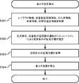
- the air flow analysis and the operation simulation performed by the power amount estimation unit 128 are substantially the same as the air flow analysis and the operation simulation performed by the temperature distribution estimation unit 125. However, the difference is that the power consumption of the improved air conditioner 20 is estimated during the operation simulation. Since the air conditioner information after the improvement includes the cooling capacity and COP of the air conditioner 20 after the improvement, the power amount estimating unit 128 uses the operation simulation to perform the air conditioning after the improvement that changes in time series from the beginning to the end. Power consumption of the device 20 can be estimated.
- the energy saving effect calculation unit 129 of the control unit 120 refers to the power amount information stored in the storage unit 110 and acquires the power consumption amount of the air conditioner 20 before the improvement that changes in a time series from the beginning to the end of the analysis time zone. (Step S303). Since the power consumption of the air conditioner 20 before the improvement is stored in the storage unit 110 in association with the measurement date and time, the energy saving effect calculation unit 129 determines the power consumption before the improvement that changes in a time series from the beginning to the end. You can get the quantity.
- the energy saving effect calculation unit 129 refers to the charge table information stored in the storage unit 110, and converts the power consumption after the improvement estimated by the power amount estimation unit 128, the power consumption before the improvement, and the charge table information. On the basis of this, the electricity rate reduced by applying the improvement to the air conditioner 20 is calculated as the energy saving effect (step S304), and the operation of the energy saving effect calculation ends. Since both the estimated power consumption after the improvement and the acquired power consumption before the improvement include a time-series change, it is possible to calculate the electricity rate based on the electricity rate table.
- the control unit 120 determines an energy saving measure based on the air conditioner information and the improved air conditioner information, and transmits the energy saving measure information and the calculated energy saving effect information to the terminal. Send to 3.
- the terminal 3 receiving the information notifies the user of the energy saving measure and the energy saving effect by displaying a screen for notifying the energy saving measure and the energy saving effect shown in FIG.
- the energy saving management system 1 has been described above.
- the energy saving management apparatus 10 estimates a temperature distribution by performing an airflow analysis and an operation simulation of the air conditioner 20, and determines an improvement point of the air conditioner 20 for energy saving based on the estimated temperature distribution.
- the energy saving management apparatus 10 estimates the power consumption of the air conditioner 20 after applying the improvement points by performing the airflow analysis and the operation simulation of the air conditioner 20 after applying the improvement points.
- the energy saving management device 10 calculates the energy saving effect based on the power consumption of the air conditioner 20 before the application of the improvement and the power consumption of the air conditioner 20 after the application of the improvement. That is, the energy saving management apparatus 10 calculates the energy saving effect based on the result of the airflow analysis and the operation simulation of the air conditioner 20. Therefore, according to the energy saving management system 1, it is possible to accurately estimate the energy saving effect by applying the improvement points.
- the energy-saving management device 10 estimates the temperature distribution of the low-temperature warehouse 2 by airflow analysis. Therefore, the energy-saving management device 10 can obtain the temperature distribution of the low-temperature warehouse 2 without installing many temperature sensors 24. Therefore, the installation cost of the temperature sensor 24 can be reduced.
- the unit cooler 21 installed in the low-temperature warehouse 2 is a model that can control the wind direction by an electric signal, and when the determined improvement is only for changing the wind direction of the unit cooler 21, the unit cooler 21 By remotely controlling the wind direction, energy can be saved.
- the control unit 120 of the energy saving management apparatus 10 transmits a command for changing the wind direction of the unit cooler 21 to the gateway 25 with reference to the improved air conditioner information stored in the storage unit 110.
- the gateway 25 that has received the command changes the wind direction of the unit cooler 21 by controlling the controller.
- the control unit 120 controls the unit cooler 21 of the air conditioner 20, it is an example of an air conditioning control unit according to the present invention.
- the improvement point determination unit 126 may determine an improvement point based on the humidity distribution estimated by the temperature distribution estimation unit 125. For example, the improvement point determination unit 126 may determine to change the wind direction to a location with high humidity. Frost, mold, and the like are likely to be generated in a high-humidity location, and the occurrence of these can be prevented by blowing a lot of wind. In this case, it can be said that the temperature distribution estimating unit 125 acquires the information of the humidity, and thus is an example of the humidity acquiring unit according to the present invention.
- a humidity sensor is installed in the low-temperature warehouse 2 and the control unit 120 sends the humidity information, which is information of the humidity measured by the humidity sensor from the gateway 25 from the gateway 25.
- the improvement point determination unit 126 may determine an improvement point based on the humidity information.
- the control unit 120 is an example of a humidity acquisition unit according to the present invention.
- the energy saving effect calculation unit 129 calculates the reduced electricity rate as the energy saving effect based on the power consumption amount and the rate table information that change in time series from the beginning to the end of the analysis time zone. However, when adopting the reduced power consumption instead of the reduced electricity rate as the energy saving effect, the energy saving effect calculator 129 determines the energy saving effect based on the difference between the power consumption at the beginning and the power consumption at the end. Can be calculated. That is, the energy-saving effect calculation unit 129 can calculate the energy-saving effect only from the power consumption at the beginning and the power consumption at the end.
- the temperature distribution estimating unit 125 refers to the temperature information acquired from the temperature sensor 24 and the weather information acquired from the weather server 4 at the time of the airflow analysis and the operation simulation of the air conditioner 20, but such information is not essential. is not. Even if there is no such information, for example, a predetermined temperature or solar radiation based on an empirical rule can be adopted as the temperature information or the weather information.
- the temperature distribution estimating unit 125 determines an error between the estimated temperature distribution and the actually measured value, and adjusts the parameter if the error is large.
- this determination and adjustment are not necessarily essential. For example, if it is desired to increase the analysis speed instead of sacrificing some accuracy, error determination and parameter adjustment may be omitted.
- the electric energy acquisition unit 127 acquires electric energy information including the electric energy measured by the electric energy meter 23 from the gateway 25.
- the temperature distribution estimating unit 125 also estimates the power consumption of the air conditioner 20 when performing the operation simulation of the air conditioner 20, and the power acquisition unit 127 determines the estimated power consumption and the date and time to be simulated. May be acquired. That is, the power consumption acquisition unit 127 may acquire the power consumption estimated at the time of the driving simulation as the first power consumption. Even when the low-temperature warehouse 2 is not provided with the watt-hour meter 23, the power-amount obtaining unit 127 obtains the power consumption estimated at the time of the driving simulation as the first power consumption.
- the power amount acquisition unit 127 can acquire the first power consumption.
- the energy saving management device 10 includes a secondary storage device 1004.
- the present invention is not limited thereto, and the secondary storage device 1004 may be provided outside the energy saving management device 10, and the energy saving management device 10 and the secondary storage device 1004 may be connected via the interface 1003.
- a removable medium such as a USB flash drive or a memory card can be used as the secondary storage device 1004.
- the energy saving management device 10 may be configured by a dedicated circuit using an ASIC (Application Specific Integrated Circuit), an FPGA (Field Programmable Gate Array), or the like. Good. Further, in the hardware configuration illustrated in FIG. 9, some of the functions of the energy saving management apparatus 10 may be realized by a dedicated circuit connected to the interface 1003, for example.
- ASIC Application Specific Integrated Circuit
- FPGA Field Programmable Gate Array
- the programs used in the energy-saving management device 10 are stored and distributed on a computer-readable recording medium such as a CD-ROM (Compact Disc Only Memory), a DVD (Digital Versatile Disc), a USB flash drive, a memory card, and an HDD. It is possible. By installing such a program on a specific or general-purpose computer, the computer can function as the energy saving management device 10.
- a computer-readable recording medium such as a CD-ROM (Compact Disc Only Memory), a DVD (Digital Versatile Disc), a USB flash drive, a memory card, and an HDD.
- the above-described program may be stored in a storage device of another server on the Internet, and the program may be downloaded from the server.
- the present invention is suitable for estimating the energy saving effect.
- 1 energy saving management system 2 low temperature warehouse, 3 terminal, 4 weather server, 10 energy saving device, 20 air conditioner, 21 unit cooler, 22 condensing unit, 23 power meter, 24 temperature sensor, 25 gateway, 100 communication unit, 110 storage unit, 120 control unit, 121 air conditioner information acquisition unit, 122 entry / exit information acquisition unit, 123 temperature acquisition unit, 124 weather information acquisition unit, 125 temperature distribution estimation unit, 126 improvement point determination unit, 127 electric energy acquisition unit , 128 power consumption estimator, 129 energy saving effect calculator, 1000 bus, 1001 processor, 1002 memory, 1003 interface, 1004 secondary storage, NT Internet.
Landscapes
- Engineering & Computer Science (AREA)
- Chemical & Material Sciences (AREA)
- Combustion & Propulsion (AREA)
- Mechanical Engineering (AREA)
- General Engineering & Computer Science (AREA)
- Signal Processing (AREA)
- Physics & Mathematics (AREA)
- Fuzzy Systems (AREA)
- Mathematical Physics (AREA)
- Thermal Sciences (AREA)
- Air Conditioning Control Device (AREA)
- Devices That Are Associated With Refrigeration Equipment (AREA)
Abstract
省エネ管理装置(10)は、気流解析と空調機(20)の運転シミュレーションとを行うことにより、低温倉庫(2)の温度分布を推定する。省エネ管理装置(10)は、推定した温度分布に基づいて、省エネのための空調機(20)の改善点を決定する。省エネ管理装置(10)は、気流解析と、改善点を適用した後の空調機(20)の運転シミュレーションとを行うことにより、改善点を適用した後の空調機(20)の消費電力量を推定する。省エネ管理装置(10)は、改善前の空調機(20)の消費電力量と、推定した改善後の空調機(20)の消費電力量と、電気料金テーブルの情報である料金テーブル情報とに基づいて、改善点の適用により削減される電気料金を省エネ効果として算出する。
Description
本発明は、省エネ管理装置、省エネ管理システム、省エネ管理方法及びプログラムに関する。
顧客が省エネ施策を導入する際に要する費用を、光熱水費の削減分で賄うESCO(Energy Service COmpany)事業が知られている。顧客及びESCO事業者は、光熱水費の削減分の一部を利益として得る。
ESCO事業の契約方式には、顧客の利益を一定額保証するものがある。当該契約下では、省エネ施策による省エネ効果が不十分である場合、十分に光熱水費を削減できないので、ESCO事業者が損害を被る。そのため、実際に省エネ施策を導入する前に省エネ効果を見積もる技術が必要とされている。
特許文献1には、省エネ施策の導入対象となる建物の情報に基づいて、過去に他の建物にて導入された省エネ施策を導入した場合の省エネ効果を評価する省エネルギー評価支援装置が開示されている。特許文献1の省エネルギー評価支援装置により、省エネ施策を導入する前に省エネ効果を見積もることができる。
しかし、特許文献1の省エネルギー評価支援装置では、精度良く省エネ効果を見積もることができないという問題がある。特許文献1の省エネルギー評価支援装置による見積もりでは、導入対象となる建物内の空調状況については何ら考慮されないので、十分な精度を得ることができない。特に、低温倉庫に省エネ施策を導入する場合には、空調状況が省エネ効果に大きな影響を及ぼし得るため、問題となる。
本発明の目的は、上記の事情に鑑み、省エネ効果を精度良く見積もる省エネ管理装置等を提供することにある。
上記の目的を達成するため、本発明に係る省エネ管理装置は、
低温倉庫のレイアウトの情報であるレイアウト情報を記憶するレイアウト記憶手段と、
前記低温倉庫の空調を行う空調機の情報である空調機情報を取得する空調機情報取得手段と、
前記低温倉庫を出入りする荷物の入出庫の情報である入出庫情報を取得する入出庫情報取得手段と、
前記空調機の消費電力量である第1の消費電力量を取得する電力量取得手段と、
前記レイアウト情報と前記空調機情報と前記入出庫情報とに基づいて、気流解析と前記空調機の運転シミュレーションとを行うことにより、前記低温倉庫の温度分布を推定する温度分布推定手段と、
前記空調機情報と前記温度分布とに基づいて、省エネのための前記空調機の改善点を決定する改善点決定手段と、
前記レイアウト情報と前記空調機情報と前記入出庫情報と前記改善点とに基づいて、気流解析と前記改善点を適用した後の前記空調機の運転シミュレーションとを行うことにより、前記改善点を適用した後の前記空調機の消費電力量である第2の消費電力量を推定する電力量推定手段と、
前記第1の消費電力量と前記第2の消費電力量とに基づいて省エネ効果を算出する省エネ効果算出手段と、
を備える。
低温倉庫のレイアウトの情報であるレイアウト情報を記憶するレイアウト記憶手段と、
前記低温倉庫の空調を行う空調機の情報である空調機情報を取得する空調機情報取得手段と、
前記低温倉庫を出入りする荷物の入出庫の情報である入出庫情報を取得する入出庫情報取得手段と、
前記空調機の消費電力量である第1の消費電力量を取得する電力量取得手段と、
前記レイアウト情報と前記空調機情報と前記入出庫情報とに基づいて、気流解析と前記空調機の運転シミュレーションとを行うことにより、前記低温倉庫の温度分布を推定する温度分布推定手段と、
前記空調機情報と前記温度分布とに基づいて、省エネのための前記空調機の改善点を決定する改善点決定手段と、
前記レイアウト情報と前記空調機情報と前記入出庫情報と前記改善点とに基づいて、気流解析と前記改善点を適用した後の前記空調機の運転シミュレーションとを行うことにより、前記改善点を適用した後の前記空調機の消費電力量である第2の消費電力量を推定する電力量推定手段と、
前記第1の消費電力量と前記第2の消費電力量とに基づいて省エネ効果を算出する省エネ効果算出手段と、
を備える。
本発明によれば、気流解析と空調機の運転シミュレーションとを行った結果に基づいて省エネ効果を算出するので、精度良く省エネ効果を見積もることができる。
以下、図面を参照しながら、本発明の実施の形態に係る省エネ管理システム等を説明する。各図面においては、同一又は同等の部分に同一の符号を付す。
(実施の形態)
図1を参照しながら、実施の形態に係る省エネ管理システム1を説明する。省エネ管理システム1は、省エネ管理装置10により、低温倉庫2を空調する空調機20についての省エネ施策を決定し、その省エネ施策による省エネ効果を見積もる。省エネ管理システム1により、例えば、ESCO事業者が、省エネ施策及びその省エネ施策による省エネ効果を、顧客である低温倉庫2の所有者に提示することができる。省エネ管理システム1は、本発明に係る省エネ管理システムの一例である。また、省エネ管理システム1によって省エネ効果を見積もる方法は、本発明に係る省エネ管理方法の一例である。
図1を参照しながら、実施の形態に係る省エネ管理システム1を説明する。省エネ管理システム1は、省エネ管理装置10により、低温倉庫2を空調する空調機20についての省エネ施策を決定し、その省エネ施策による省エネ効果を見積もる。省エネ管理システム1により、例えば、ESCO事業者が、省エネ施策及びその省エネ施策による省エネ効果を、顧客である低温倉庫2の所有者に提示することができる。省エネ管理システム1は、本発明に係る省エネ管理システムの一例である。また、省エネ管理システム1によって省エネ効果を見積もる方法は、本発明に係る省エネ管理方法の一例である。
なお、本実施の形態においては、省エネ施策の導入により削減できる光熱水費を省エネ効果として見積もる。しかし、光熱水費以外の指標を省エネ効果として見積もってもよい。例えば、省エネ施策の導入により削減できる消費電力量を省エネ効果として見積もってもよい。
省エネ管理システム1は、省エネ管理装置10と、空調機20と、電力量計23と、複数の温度センサ24と、ゲートウェイ25と、端末3と、気象サーバ4と、を備える。空調機20、電力量計23、温度センサ24及びゲートウェイ25は、低温倉庫2に設けられている。省エネ管理装置10は、インターネットNTを介して、ゲートウェイ25、端末3及び気象サーバ4と通信する。空調機20、電力量計23及び温度センサ24は、ゲートウェイ25と通信可能に接続されている。図1では、空調機20は1つのみ示されているが、空調機20は複数であってもよい。
省エネ管理装置10は、空調機20についての省エネ施策を決定し、その省エネ施策による省エネ効果を見積もる装置である。省エネ管理装置10は、例えばESCO事業者が運営するクラウドサーバである。省エネ施策は、省エネのための空調機20の改善点を決定することにより定められる。空調機20の改善点とは、例えば、風向の変更、最新機種への変更などである。省エネ管理装置10は、本発明に係る省エネ管理装置の一例である。省エネ管理装置10の機能的構成については後述する。
低温倉庫2は、荷物を低温で保存するための倉庫である。低温倉庫2は、例えば、食料品を-20℃程度の低温で冷凍保存するための冷凍倉庫である。低温倉庫2は、本発明に係る低温倉庫の一例である。
空調機20は、低温倉庫2を空調する空調機である。空調機20は、例えば、ESCO事業者により設置された冷凍用の空調機である。空調機20は、室内機であるユニットクーラ21と、室外機であるコンデンシングユニット22と、を備える。ユニットクーラ21は、低温倉庫2内に設置される。コンデンシングユニット22は、低温倉庫2外に設置される。ユニットクーラ21には、機種に応じて、制御信号により風向を変更できるものもあれば、人手によらなければ風向を変更できないものもある。空調機20は、運転時間、稼働率、冷媒温度、冷凍能力など、空調機の運転中に動的に変動し得る情報である運転情報を定期的にゲートウェイ25に送信する。冷凍能力は、風量、吸い込み温度、吹き出し温度など運転中の状況に応じて変動するので、運転情報である。空調機20は、本発明に係る空調機の一例である。
電力量計23は、低温倉庫2の消費電力量を測定する。電力量計23は、例えば、ESCO事業者により設置されたスマートメータである。低温倉庫2の消費電力量のうちほとんどが空調機20の運転によるものであると考えられるので、電力量計23により測定される消費電力量は、空調機20の消費電力量とほぼ等しくなる。電力量計23は、測定した消費電力量を定期的にゲートウェイ25に送信する。
複数の温度センサ24のそれぞれは、自身の周囲の空気温度を測定する。温度センサ24は、低温倉庫2内に設置されている。各温度センサ24は、例えば、ESCO事業者により設置されたスマート温度計である。複数の温度センサ24により複数箇所の空気温度を測定することができる。そのため、複数の温度センサ24により、低温倉庫2内の大まかな温度分布を測定することができる。各温度センサ24は、測定した空気温度を定期的にゲートウェイ25に送信する。温度センサ24が多いほど、温度分布を精度良く測定することができるが、温度センサ24の設置コストが高くなる。そのため、温度センサ24は、出入り口、荷物が多く置かれる箇所など、温度変化が起こりやすい箇所に重点的に設置されることが好ましい。温度センサ24は、本発明に係る温度センサの一例である。
ゲートウェイ25は、空調機20、電力量計23及び各温度センサ24を統括管理する装置である。ゲートウェイ25は、例えば、ESCO事業者により低温倉庫2の近辺に設置される。ゲートウェイ25は、空調機20、電力量計23及び各温度センサ24から、運転情報、消費電力量及び空気温度を受信する。
ゲートウェイ25には、後述の省エネ効果算出の際に必要となる各種情報が予め登録されている。上記の各種情報は、ユニットクーラ21の位置、風向、風量、性能及び機種に関する情報、コンデンシングユニット22の性能及び機種に関する情報、各温度センサ24の設置位置に関する情報を含む。これらの情報は、例えば、空調機20、温度センサ24及びゲートウェイ25の設置後に、ESCO事業者によりゲートウェイ25に登録される。
ゲートウェイ25は、空調機20から受信した運転情報と、登録されている情報のうち空調機20に関する情報とを、空調機情報として省エネ管理装置10に送信する。ゲートウェイ25は、電力量計23から受信した消費電力量と測定日時とを関連付けた電力量情報を省エネ管理装置10に送信する。ゲートウェイ25は、各温度センサ24から受信した空気温度と測定日時と各温度センサ24の設置位置とを関連付けた温度情報を省エネ管理装置10に送信する。
端末3は、各種情報を省エネ管理装置10と送受信する装置である。端末3のユーザは、例えば低温倉庫2の所有者である。端末3は、例えば、パーソナルコンピュータ、スマートフォン、タブレット端末などである。端末3は、低温倉庫2のレイアウトの情報であるレイアウト情報と、低温倉庫2を出入りする荷物の入出庫の情報である入出庫情報と、低温倉庫2に適用される電気料金テーブルの情報である料金テーブル情報と、を省エネ管理装置10に送信する。端末3が省エネ管理装置10に送信するこれらの情報は、例えば、端末3のユーザである低温倉庫2の所有者によって入力される。
端末3は、省エネ管理装置10から、省エネ管理装置10により決定された省エネ施策に関する情報と、当該省エネ施策による省エネ効果の見積もりに関する情報とを受信する。端末3は、受信したこれらの情報が示す内容をユーザに報知する。端末3のユーザは、端末3にて報知された省エネ施策及び当該省エネ施策による省エネ効果の見積もりを確認し、省エネ施策を導入するか否かを判断する。
気象サーバ4は、気象情報を配信するためのサーバである。気象サーバ4は、例えば気象庁が運営するサーバである。気象サーバ4は、低温倉庫2の設置された地域の気象情報を省エネ管理装置10に送信する。気象情報は、外気温と日射量とを含む。
図2を参照しながら、省エネ管理装置10の機能的構成を説明する。省エネ管理装置10は、通信部100と、記憶部110と、制御部120と、を備える。
通信部100は、インターネットNTを介して、ゲートウェイ25、端末3及び気象サーバ4と通信する。制御部120及び後述する制御部120の各機能部は、通信部100を介して、ゲートウェイ25、端末3及び気象サーバ4と情報の送受信をすることとなる。
記憶部110は、レイアウト情報と、空調機情報と、入出庫情報と、消費電力量の情報である電力量情報と、温度情報と、気象情報と、料金テーブル情報と、改善点を空調機20に適用したと仮定したときの空調機20の情報である改善後空調機情報と、を記憶する。以下、記憶部110が記憶する各情報を説明する。
レイアウト情報は、低温倉庫2のレイアウトの情報である。レイアウト情報は、例えば、低温倉庫2の建築図面を表す情報である。レイアウト情報により表される室内空間が、後述の気流解析の対象となる空間である。記憶部110は、レイアウト情報を記憶するので、本発明に係るレイアウト記憶手段の一例である。
空調機情報は、空調機20の情報であり、ユニットクーラ21の情報とコンデンシングユニット22の情報とを含む。
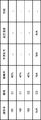
図3を参照しながら、空調機情報に含まれる、ユニットクーラ21の情報を説明する。図3に示すとおり、ユニットクーラ21の情報は、設置されたユニットクーラ21を個別に識別するための識別子、ユニットクーラ21の機種、ユニットクーラ21の位置、ユニットクーラ21の風向、ユニットクーラ21の風量、ユニットクーラ21の性能及びユニットクーラ21と接続されたコンデンシングユニット22の識別子を示す情報を含む。識別子としては、例えば製造番号が採用可能である。あるいは、省エネ管理装置10により自動的に生成された文字列を採用してもよい。ユニットクーラ21の性能は、例えば、ユニットクーラ21の製品カタログにて示された性能である。
なお、ユニットクーラ21の情報は、低温倉庫2に設置されていない機種の情報も含む。例えば、図3には、識別子が設定されていない機種U3のユニットクーラ21の情報が示されている。後述の改善点の決定において、ユニットクーラ21の機種を変更する場合があるため、記憶部110は、設置されていない機種の情報も記憶する。これらの情報は、例えば、ESCO事業者により予め準備される。
図4を参照しながら、空調機情報に含まれる、コンデンシングユニット22の情報を説明する。図4に示すとおり、コンデンシングユニット22の情報は、設置されたコンデンシングユニット22を個別に識別するための識別子、コンデンシングユニット22の機種、コンデンシングユニット22の稼働率、コンデンシングユニット22の冷凍能力、コンデンシングユニット22の設定温度及びコンデンシングユニット22の性能を示す情報を含む。識別子及び性能に関しては、ユニットクーラ21の場合と同様である。ただし、コンデンシングユニット22の性能を示す情報は、コンデンシングユニット22のエネルギー消費効率を示すCOP(Coefficient Of Performance)を含む。COPは、後述の消費電力推定の際に使用される。また、ユニットクーラ21の場合と同様の理由により、コンデンシングユニット22の情報は、設置されていない機種の情報を含む。
図5を参照しながら、入出庫情報を説明する。入出庫情報は、低温倉庫2を出入りする荷物の入出庫の情報である。図5に示すとおり、入出庫情報は、入出庫の日時の情報と、入庫か出庫かを示す情報と、荷物の位置の情報と、荷物の重量の情報と、荷物の温度状態を示す情報と、を含む。荷物の位置とは、荷物が入庫される場合は入庫された荷物が置かれた位置であり、荷物が出庫される場合は出庫前に荷物が置かれていた位置である。荷物の温度状態とは、荷物が常温であるか冷凍されているかを表す状態である。記憶部110は、入出庫情報を時系列的に記憶する。
電力量情報は、低温倉庫2の消費電力量と、消費電力量の測定日時とが関連付けられた情報である。上述のとおり、当該消費電力量は、空調機20の消費電力量とほぼ等しい。記憶部110は、電力量情報を時系列的に記憶する。
図6を参照しながら、温度情報を説明する。温度情報は、各温度センサ24が測定した空気温度の情報である。図6に示すとおり、温度情報は、空気温度の測定日時、温度センサ24の位置及び測定された空気温度を示す情報を含む。記憶部110は、温度情報を時系列的に記憶する。
図7を参照しながら、気象情報を説明する。記憶部110が記憶する気象情報は、気象サーバが配信する、低温倉庫2が設置された地域の気象情報である。気象情報は、日時、当該日時における外気温及び当該日時における日射量を示す情報を含む。記憶部110は、気象情報を時系列的に記憶する。
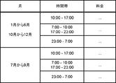
図8を参照しながら、料金テーブル情報を説明する。料金テーブル情報は、低温倉庫2に適用される電気料金テーブルの情報である。図8に示す例では、月及び時間帯に応じて電気料金が設定されていることが示されている。図8に示す例に限らず、料金テーブル情報は、基本料金、割引条件などの情報を含んでもよい。記憶部110は、料金テーブル情報を記憶するので、本発明に係る料金テーブル記憶手段の一例である。
改善後空調機情報は、省エネのための改善点を適用したと仮定したときの空調機20の情報である。改善後空調機情報が示す情報は、空調機情報と同様である。ただし、改善後空調機情報は、改善点を適用した場合の空調機の情報であるので、空調機情報とは内容が異なる。例えば、ユニットクーラ21の風向変更が改善点に含まれる場合、当該ユニットクーラ21の風向を示す情報が、空調機情報と改善後空調機情報とで異なる。
再び図2を参照する。制御部120は、省エネ管理装置10を統括制御する。制御部120は、空調機情報取得部121と、入出庫情報取得部12と、温度取得部123と、気象情報取得部124と、温度分布推定部125と、改善点決定部126と、電力量取得部127と、電力量推定部128と、省エネ効果算出部129と、を備える。
空調機情報取得部121は、ゲートウェイ25から空調機情報を取得し、記憶部110に保存する。空調機情報取得部121は、本発明に係る空調機情報取得手段の一例である。
入出庫情報取得部12は、端末3から入出庫情報を取得し、記憶部110に保存する。入出庫情報取得部12は、本発明に係る入出庫情報取得手段の一例である。
温度取得部123は、ゲートウェイ25から温度情報を取得し、記憶部110に保存する。温度取得部123は、本発明に係る温度取得手段の一例である。
気象情報取得部124は、気象サーバ4から気象情報を取得し、記憶部110に保存する。気象情報取得部124は、本発明に係る気象情報取得手段の一例である。
温度分布推定部125は、気流解析と空調機20の運転シミュレーションとを行うことにより、低温倉庫2の温度分布を推定する。温度分布推定部125は、記憶部110から、レイアウト情報、空調機情報、温度情報及び気象情報を取得する。温度分布推定部125は、気流解析及び運転シミュレーションを行う対象とする時間帯を決定する。温度分布推定部125は、対象とした時間帯における低温倉庫2の空気の流れ及び熱の移動を、気流解析を行うことによりシミュレーションする。気流解析の方法として、例えば熱流体解析による方法が採用可能である。気流解析の際、並行して空調機20の運転シミュレーションも行うことにより、ユニットクーラ21から吹き出す空気も気流解析の対象とすることができる。温度分布推定部125は、レイアウト情報、空調機情報、温度情報及び気象情報に基づいて気流解析及び運転シミュレーションを行う。温度分布推定部125は、気流解析の結果として、低温倉庫2の温度分布を得ることができる。得られた温度分布が、推定された温度分布となる。温度分布推定部125は、本発明に係る温度分布推定手段の一例である。
改善点決定部126は、省エネのための空調機20の改善点を決定する。改善点決定部126は、空調機情報と温度分布推定部125が推定した温度分布とに基づいて、空調機20の改善点を決定する。改善点決定部126は、決定した改善点を空調機20に適用したと仮定したときの空調機情報である改善後空調機情報を作成し、記憶部110に保存する。改善点決定部126は、本発明に係る改善点決定手段の一例である。
電力量取得部127は、ゲートウェイ25から電力量情報を取得し、記憶部110に保存する。電力量取得部127は、本発明に係る電力量取得手段の一例である。電力量取得部127により取得される電力量情報にて示される消費電力量は、本発明に係る第1の消費電力量の一例である。
電力量推定部128は、改善点決定部126が決定した改善点を適用した後の空調機20の消費電力量を、気流解析と改善点を適用した後の空調機20の運転シミュレーションとを行うことにより推定する。電力量推定部128は、記憶部110から、レイアウト情報、改善後空調機情報、温度情報及び気象情報を取得する。電力量推定部128は、温度分布推定部125と同様に、気流解析と運転シミュレーションとを並行して行う。電力量推定部128は、レイアウト情報、改善後空調機情報、温度情報及び気象情報に基づいて気流解析及び運転シミュレーションを行う。電力量推定部128は、運転シミュレーションの際に、時系列的に変化する改善後の空調機20の消費電力量を推定する。電力量推定部128は、本発明に係る電力量推定手段の一例である。電力量推定部128により推定される消費電力量は、本発明に係る第2の消費電力量の一例である。
省エネ効果算出部129は、空調機20への改善点の適用による省エネ効果を見積もる。省エネ効果算出部129は、記憶部110から電力量情報と料金テーブル情報とを取得する。電力量情報は、時系列的に変化する改善前の消費電力量を示す。省エネ効果算出部129は、改善前の消費電力量と、電力量推定部128が推定した改善後の消費電力量と、料金テーブル情報と、に基づいて、改善点の適用により削減された電気料金を省エネ効果として算出する。省エネ効果算出部129は、本発明に係る省エネ効果算出手段の一例である。
制御部120は、端末3からレイアウト情報を取得して、記憶部110に保存する。制御部120は、記憶部110が記憶する空調機情報と改善後空調機情報とに基づいて省エネ施策を決定し、決定した省エネ施策の情報を端末3に送信する。制御部120は、省エネ効果算出部129が算出した省エネ効果の情報を端末3に送信する。
次に、省エネ管理装置10のハードウェア構成の一例を、図9を参照しながら説明する。図9に示す省エネ管理装置10は、例えばパーソナルコンピュータ、ブレードサーバなどのコンピュータにより実現される。
省エネ管理装置10は、バス1000を介して互いに接続された、プロセッサ1001と、メモリ1002と、インタフェース1003と、二次記憶装置1004と、を備える。
プロセッサ1001は、例えばCPU(Central Processing Unit: 中央演算装置)である。プロセッサ1001が、二次記憶装置1004に記憶された管理プログラムをメモリ1002に読み込んで実行することにより、省エネ管理装置10の各機能が実現される。なお、当該管理プログラムから後述の気流解析用プログラムが呼び出されて実行されることにより、温度分布推定部125の機能が実現されてもよい。
メモリ1002は、例えば、RAM(Random Access Memory)により構成される主記憶装置である。メモリ1002は、プロセッサ1001が二次記憶装置1004から読み込んだプログラムを記憶する。また、メモリ1002は、プロセッサ1001がプログラムを実行する際のワークメモリとして機能する。
インタフェース1003は、例えばシリアルポート、USB(Universal Serial Bus)、ネットワークインタフェースなどのI/O(Input/Output)インタフェースである。
二次記憶装置1004は、例えば、フラッシュメモリ、HDD(Hard Disk Drive)、SSD(Solid State Drive)である。二次記憶装置1004は、プロセッサ1001が実行する管理プログラムを記憶する。また、当該管理プログラムから気流解析用プログラムが呼び出される場合、当該気流解析用のプログラムも記憶する。当該気流解析用プログラムとして、市販の気流解析用プログラムを採用することもできる。また、二次記憶装置1004により、記憶部110の機能が実現される。
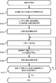
次に、図10を参照しながら、省エネ管理装置10による温度分布推定の動作の一例を説明する。図10に示す動作を、1月ごと、季節ごとなど、定期的に実行されるものでもよいし、省エネ管理装置10の運営者であるESCO事業者により任意のタイミングで実行されるものでもよい。また、図10に示す動作が実行されるとき、すでに記憶部110には、図10に示す動作を実行するために必要なレイアウト情報、空調機情報、入出庫情報、気象情報及び温度情報が保存されているものとする。
省エネ管理装置10の制御部120の温度分布推定部125は、気流解析を行う対象とする時間帯を決定する(ステップS101)。以下、この時間帯を「解析時間帯」という。例えば、温度分布推定部125は、現在より24時間前から現在までを、解析時間帯として決定する。あるいは、温度分布推定部125は、荷物の出入りの頻度が高いと推測される平日の日中時間帯を解析時間帯として決定してもよい。
温度分布推定部125は、記憶部110から、レイアウト情報、空調機情報、入出庫情報及び気象情報を取得する(ステップS102)。温度分布推定部125は、入出庫情報のうち、入出庫の日時が解析時間帯に含まれる入出庫情報のみを取得すればよい。同様に、温度分布推定部125は、気象情報のうち、日時が解析時間帯に含まれる気象情報のみを取得すればよい。
温度分布推定部125は、記憶部110から、解析時間帯の始期の温度情報を取得する(ステップS103)。例えば、解析時間帯の始期が2018年7月30日0時0分である場合、温度分布推定部125は、測定日時が2018年7月30日0時0分に最も近い温度情報を取得する。この動作により、解析時間帯の始期における低温倉庫2の大まかな温度分布を取得できる。以下、解析時間帯の始期を単に「始期」という。また、解析時間帯の終期を単に「終期」という。
温度分布推定部125は、気流解析にて使用するパラメータを決定する(ステップS104)。決定されるパラメータは、低温倉庫2の壁面の断熱係数、低温倉庫2を出入りする荷物の熱容量、低温倉庫2を出入りする作業者の熱容量などである。これらのパラメータは、経験則に基づいて予め定められる値であってもよいし、低温倉庫2の所有者またはESCO事業者により入力される値であってもよい。
温度分布推定部125は、取得したレイアウト情報、空調機情報、入出庫情報、気象情報及び始期の温度情報と、ステップS104にて決定したパラメータとに基づいて、気流解析及び空調機20の運転シミュレーションによる低温倉庫2の温度分布の推定を行う(ステップS105)。より具体的には、温度分布推定部125は、始期から終期までを対象として、気流解析によるシミュレーション及び空調機20の運転シミュレーションを並行して実行し、低温倉庫2の温度分布を推定する。
以下、温度分布推定部125が行う気流解析の一例を説明する。まず、温度分布推定部125は、始期における低温倉庫2の温度分布を決定する。つまり、解析に使用される初期値を決定する。温度センサ24が設置されていない場所の空気温度は不明であるが、例えば最も近い温度センサ24による測定温度を採用する。次に、温度分布推定部125は、以下に説明する各解析を並行して実行する。
温度分布推定部125は、レイアウト情報と断熱係数と気象情報とに基づいて、熱伝導により低温倉庫2の外部から流入する熱を解析する。熱伝導により流入する熱とは、外気から壁面を通じて流入する熱、日射により熱せられた壁面から流入する熱などである。気象情報から外気温と日射量がわかり、レイアウト情報から壁面の位置がわかる。したがって、温度分布推定部125は、これらの情報に基づく解析をすることができる。
温度分布推定部125は、レイアウト情報と気象情報と入出庫情報とに基づいて、低温倉庫2の出入り口を出入りする空気の気流及び気流による熱移動を解析する。入出庫情報に含まれる入出庫の日時から、低温倉庫2の出入り口が開かれた日時が推定できる。レイアウト情報から、出入り口の位置及び大きさがわかる。また、レイアウト情報から、気流の移動可能範囲もわかる。気象情報から外気温がわかる。したがって、温度分布推定部125は、これらの情報に基づく解析することができる。
温度分布推定部125は、レイアウト情報と入出庫情報と熱容量とに基づいて、荷物の出入り及び作業者の出入りによる熱移動を解析する。温度分布推定部125は、レイアウト情報と入出庫情報から、荷物及び作業者の動きが推定できる。そして、温度分布推定部125は、推定した動きと熱容量から熱移動を解析できる。
温度分布推定部125は、レイアウト情報、空調機情報及び気象情報と、並行して行われる空調機20の運転シミュレーションとに基づいて、ユニットクーラ21から吹き出される空気の気流及び気流による熱移動を解析する。空調機情報から、ユニットクーラ21から吹き出される空気の風向及び風量がわかる。また、運転シミュレーションから、ユニットクーラ21から吹き出される空気の吹き出し温度がわかる。したがって、温度分布推定部125は、これらの情報に基づく解析をすることができる。
空調機20の運転シミュレーションは、空調機情報、気象情報及び気流解析により得られるユニットクーラ21の周囲温度に基づいて行われる。空調機情報は、コンデンシングユニット22の稼働率、冷却能力、設定温度及び性能を示す情報を含む。したがって、運転シミュレーションにより、これらの情報と気象情報が示す外気温と気流解析により得られるユニットクーラ21の周囲温度とに基づいて、ユニットクーラ21から吹き出される空気の吹き出し温度を求めることができる。
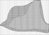
温度分布推定部125は、上記の各解析によるシミュレーションを始期から終期まで実行することにより、終期における低温倉庫2の温度分布を得ることができる。例えば、シミュレーションの結果、図11に示す温度分布が得られる。図11は、低温倉庫2の温度等高線を示すコンター図である。図11は平面図であるが、これはある高さにおける温度分布を示すものであり、実際には三次元空間における温度分布が得られる。
温度分布推定部125は、終期の温度情報を取得する(ステップS106)。温度分布推定部125は、推定した温度分布のうち温度センサ24が設置された位置に相当する各箇所の空気温度と、終期の温度情報が示す各箇所の空気温度との誤差が許容範囲内か否かを判定する(ステップS107)。つまり、温度分布推定部125は、推定した温度分布と実測値との誤差が許容範囲か否かを判定する。許容範囲内とは、例えば、判定対象となる全ての箇所で誤差が2℃以下となっていることである。あるいは、全箇所のうち9割の箇所で誤差が2℃以下となっていることとしてもよい。この動作は、推定結果が妥当か否かを判定することに相当する。
誤差が許容範囲内であると判定したとき(ステップS107:Yes)、温度分布推定部125は、温度分布推定の動作を終了する。推定した温度分布は、後述の改善点決定に用いられる。
誤差が許容範囲内ではないと判定したとき(ステップS107:No)、温度分布推定部125は、ステップS104のパラメータ決定からの動作の流れを繰り返す。パラメータを再び決定する際に、温度分布推定部125は、誤差に基づいてパラメータを決定する。例えば、全体的に誤差が生じている場合、温度分布推定部125は、断熱係数のパラメータを調整する。局所的に誤差が生じている場合、温度分布推定部125は、誤差が生じている箇所の周辺の荷物の設置状況を考慮し、熱容量のパラメータを調整する。いずれの場合も、温度分布推定部125は、誤差を減らすためにパラメータを調整する。パラメータ調整後再び温度分布を推定することにより、誤差の少ない温度分布が得られることが期待できる。
なお、気流解析の方法あるいはパラメータの調整方法次第では、温度分布推定部125は、ステップS104からステップS107までの動作の流れを無限に繰り返してしまうおそれがある。この繰り返しを回避するため、温度分布推定部125は、ステップS107における許容範囲を順次広げてもよいし、一定回数以上ステップS107の判定を行ったら動作を終了してもよい。
次に、図12を参照しながら、省エネ管理装置10による改善点決定の動作の一例を説明する。この動作により、省エネのために空調機20に適用すべき改善点が決定される。図12に示す動作は、例えば上述の温度分布の推定の終了後に実行される。
省エネ管理装置10の制御部120の改善点決定部126は、推定された温度分布に基づいて、低温倉庫2全体の空気温度がコンデンシングユニット22の設定温度よりT1℃以上低いか否かを判定する(ステップS201)。この動作は、低温倉庫2全体を過剰に冷却しているか否かを判定することに相当する。T1℃は、例えば2℃である。なお、冷気は下にたまりやすい性質があることから、低温倉庫2全体の空気温度ではなく、一定の高さ以下の空間領域の空気温度のみを判定対象としてもよい。例えば、荷物が積まれる最大の高さ以下の空間領域の空気温度のみを判定対象としてもよい。
低温倉庫2全体の空気温度が設定温度よりT1℃以上低いと判定したとき(ステップS201:Yes)、改善点決定部126は、コンデンシングユニット22の設定温度を上げることを改善点として決定する(ステップS202)。改善点決定部126は、例えば、設定温度を1℃上げることを改善点として決定する。コンデンシングユニット22の設定温度を上げることにより過剰な冷却を防ぐことができるので、省エネ効果が期待できる。
決定後、改善点決定部126は、ステップS203以降の動作を実行する。ステップS201にてNoと判定したとき、改善点決定部126は、そのままステップS203以降の動作を実行する。
改善点決定部126は、推定された温度分布に基づいて、低温倉庫2全体の空気温度のうち、最高温度と最低温度との差がT2℃以上あるか否かを判定する(ステップS203)。この動作は、低温倉庫2に一定以上の温度ムラが存在するか否かを判定することに相当する。T2℃は、例えば3℃である。ステップS201の場合と同様に、低温倉庫2全体の空気温度ではなく、一定の高さ以下の空間領域の空気温度のみを判定対象としてもよい。
最高温度と最低温度との差がT2℃以上あると判定した時(ステップS203:Yes)、改善点決定部126は、温度ムラを減少させるためにユニットクーラ21の風向及び位置を変更することを改善点として決定する(ステップS204)。温度ムラを減少させることにより冷却効率が改善するので、省エネ効果が期待できる。ユニットクーラ21の風向及び位置は、推定された温度分布に基づいて決定する。例えば、改善点決定部126は、空気温度が高い箇所を重点的に冷却するために、ユニットクーラ21の風向及び位置を決定する。改善点決定部126は、可能であればユニットクーラ21の風向のみの変更を改善点として決定するが、ユニットクーラ21の位置を変更しなければ温度ムラの減少が困難である場合には、ユニットクーラ21の位置の変更も改善点として決定する。
決定後、改善点決定部126は、ステップS205以降の動作を実行する。最高温度と最低温度との差がT2℃未満であると判定した時(ステップS203:No)、改善点決定部126は、そのままステップS205以降の動作を実行する。
改善点決定部126は、空調機情報に基づいて、稼働率が閾値以下のコンデンシングユニット22があるか否かを判定する(ステップS205)。閾値は、例えば40%である。
稼働率が閾値以下のコンデンシングユニット22があると判定したとき(ステップS205:Yes)、改善点決定部126は、稼働率の改善のために必要な事項を改善点として決定する(ステップS206)。稼働率の低いコンデンシングユニット22が複数存在する場合、稼働率の低いコンデンシングユニット22の一部または全部の動作を停止させ、動作を停止させていないコンデンシングユニット22の稼働率を高くすることにより、低温倉庫2に設けられた空調機20全体のエネルギー効率を改善できる。そのため、改善点決定部126は、稼働率の低いコンデンシングユニット22の停止を改善点として決定する。
この際、一部のコンデンシングユニット22の動作を停止させることにより、当該コンデンシングユニット22と接続されたユニットクーラ21からの送風が停止される。そのため、当該ユニットクーラ21により本来空調されていた空間を空調するために、他のユニットクーラ21の風向を変更することも改善点として決定する。
決定後、改善点決定部126は、ステップS207以降の動作を実行する。稼働率が閾値以下のコンデンシングユニット22がないと判定したとき(ステップS205:No)、改善点決定部126は、そのままステップS207以降の動作を実行する。
改善点決定部126は、空調機情報に基づいて、現在設置されているコンデンシングユニット22を最新機種に交換可能か否かを判定する(ステップS207)。例えば、改善点決定部126は、現在設置されているコンデンシングユニット22と同馬力であり、エネルギー効率が改善されている最新機種があるか否かを判定することにより、コンデンシングユニット22を最新機種に交換可能か否かを判定する。
コンデンシングユニット22を最新機種に交換可能であると判定したとき(ステップS207:Yes)、改善点決定部126は、コンデンシングユニット22の機種変更を改善点として決定する(ステップS208)。決定後、改善点決定部126は、ステップS209以降の動作を実行する。コンデンシングユニット22を最新機種に交換可能ではないと判定したとき(ステップS207:No)、改善点決定部126は、そのままステップS209以降の動作を実行する。
改善点決定部126は、上記の動作にて決定した改善点を空調機20に適用したと仮定した場合の空調機20の情報である改善後空調機情報を作成し、記憶部110に保存する(ステップS209)。そして改善点決定部126は、改善点決定の動作を終了する。
次に、図13を参照しながら、省エネ管理装置10による省エネ効果算出の動作の一例を説明する。図13に示す動作は、例えば上記の改善点決定の終了後に実行される。
省エネ管理装置10の制御部120の電力量推定部128は、記憶部110から、レイアウト情報、改善後空調機情報、入出庫情報、気象情報及び始期の温度情報を取得する(ステップS301)。
電力量推定部128は、気流解析及び改善後の空調機20の運転シミュレーションを並行して行うことにより、改善後の空調機20の消費電力量を推定する(ステップS302)。電力量推定部128により行われる気流解析及び運転シミュレーションは、概ね温度分布推定部125により行われる気流解析及び運転シミュレーションと同様である。ただし、運転シミュレーションの際に、改善後の空調機20の消費電力量を推定する点が異なる。改善後の空調機情報には、改善後の空調機20の冷却能力及びCOPが含まれるので、電力量推定部128は、運転シミュレーションにより、始期から終期まで時系列的に変化する改善後の空調機20の消費電力量を推定することができる。
制御部120の省エネ効果算出部129は、記憶部110が記憶する電力量情報を参照し、解析時間帯の始期から末期まで時系列的に変化する改善前の空調機20の消費電力量を取得する(ステップS303)。記憶部110には、改善前の空調機20の消費電力量が測定日時と関連付けて保存されているため、省エネ効果算出部129は、始期から末期まで時系列的に変化する改善前の消費電力量を取得できる。
省エネ効果算出部129は、記憶部110が記憶する料金テーブル情報を参照し、電力量推定部128により推定された改善後の消費電力量と、改善前の消費電力量と、料金テーブル情報とに基づいて、改善点を空調機20に適用することにより削減される電気料金を省エネ効果として算出し(ステップS304)、省エネ効果算出の動作を終了する。推定された改善後の消費電力量及び取得した改善前の消費電力量のいずれも、時系列的な変化も含むものであるため、電気料金テーブルに基づいて電気料金を算出することができる。
上記の省エネ効果算出の動作の終了後、制御部120は、空調機情報と改善後空調機情報とに基づいて省エネ施策を決定し、省エネ施策の情報と算出された省エネ効果の情報とを端末3に送信する。当該情報を受信した端末3は、図14に示す省エネ施策及び省エネ効果を報知する画面を表示することにより、省エネ施策及び省エネ効果をユーザに報知する。
以上、実施の形態に係る省エネ管理システム1を説明した。まず、省エネ管理装置10が、気流解析と空調機20の運転シミュレーションとを行うことにより温度分布を推定し、推定した温度分布に基づいて省エネのための空調機20の改善点を決定する。次に、省エネ管理装置10が、気流解析と改善点を適用した後の空調機20の運転シミュレーションとを行うことにより、改善点を適用した後の空調機20の消費電力量を推定する。そして、省エネ管理装置10が、改善点適用前の空調機20の消費電力量と改善点適用後の空調機20の消費電力量とに基づいて省エネ効果を算出する。つまり、省エネ管理装置10は、気流解析と空調機20の運転シミュレーションとを行った結果に基づいて省エネ効果を算出する。そのため、省エネ管理システム1によれば、改善点の適用による省エネ効果を精度良く見積もることができる。
また、省エネ管理システム1によれば、省エネ管理装置10は、気流解析により低温倉庫2の温度分布を推定する。そのため、温度センサ24を多く設置しなくとも、省エネ管理装置10は低温倉庫2の温度分布を得ることができる。そのため、温度センサ24の設置コストを削減できる。
(変形例)
上記の実施の形態では、決定した改善点に基づく省エネ施策及び省エネ効果を顧客に提示するのみであるが、決定した改善点に基づいて空調機20を制御してもよい。
上記の実施の形態では、決定した改善点に基づく省エネ施策及び省エネ効果を顧客に提示するのみであるが、決定した改善点に基づいて空調機20を制御してもよい。
例えば、低温倉庫2に設置されているユニットクーラ21が、電気信号により風向制御可能な機種である場合、かつ決定した改善点がユニットクーラ21の風向を変更するもののみである場合、ユニットクーラ21の風向を遠隔制御することにより、省エネを図ることができる。
例えば、空調機20にコントローラが接続されており、ゲートウェイ25がコントローラを制御することでユニットクーラ21の風向を変更できる場合を考える。この場合、省エネ管理装置10の制御部120は、記憶部110が記憶する改善後空調機情報を参照して、ユニットクーラ21の風向を変更するためのコマンドをゲートウェイ25に送信する。当該コマンドを受信したゲートウェイ25は、コントローラを制御してユニットクーラ21の風向を変更する。この場合、制御部120は空調機20のユニットクーラ21を制御するので、本発明に係る空調制御手段の一例である。
また、温度分布推定部125による気流解析及び空調機20の運転シミュレーションでは、温度分布のみではなく湿度分布も推定できる。そこで、改善点決定部126は、温度分布推定部125により推定された湿度分布に基づいて改善点を決定してもよい。例えば、改善点決定部126は、湿度の高い箇所に風向を変更することを決定してもよい。湿度の高い箇所は霜、カビなどが発生しやすいため、風を多く当てることによりこれらの発生を防ぐことができる。この場合、温度分布推定部125は、湿度の情報を取得するともいえるので、本発明に係る湿度取得手段の一例である。
また、気流解析及び空調機20の運転シミュレーションにより湿度分布を推定する代わりに、低温倉庫2に湿度センサを設置し、制御部120がゲートウェイ25から当該湿度センサが測定した湿度の情報である湿度情報を取得し、改善点決定部126は当該湿度情報に基づいて改善点を決定してもよい。この場合、制御部120が本発明に係る湿度取得手段の一例である。
また、省エネ効果算出部129は、解析時間帯の始期から終期まで時系列的に変化する消費電力量と料金テーブル情報とに基づいて、削減される電気料金を省エネ効果として算出した。しかし、省エネ効果として削減される電気料金ではなく削減される消費電力量を採用する場合、省エネ効果算出部129は、始期における消費電力量と終期における消費電力量との差分に基づいて省エネ効果を算出できる。つまり、省エネ効果算出部129は、始期における消費電力量及び終期における消費電力量のみで省エネ効果を算出できる。
また、温度分布推定部125は、気流解析及び空調機20の運転シミュレーションの際に、温度センサ24から取得した温度情報及び気象サーバ4から取得した気象情報を参照するが、これらの情報は必ずしも必須ではない。これらの情報がない場合であっても、例えば経験則に基づいて予め定められた温度あるいは日射量を温度情報あるいは気象情報として採用可能である。
また、温度分布推定部125は、推定した温度分布と実測値との誤差を判定し、誤差が大きい場合にはパラメータを調整するが、この判定及び調整は必ずしも必須ではない。例えば、精度を多少犠牲にしてもよい代わりに解析速度を高速にしたい場合には、誤差判定及びパラメータの調整を省略してもよい。
また、電力量取得部127は、電力量計23が測定した電力量を含む電力量情報をゲートウェイ25から取得した。しかし、温度分布推定部125が、空調機20の運転シミュレーションを行う際に空調機20の消費電力量も推定し、電力量取得部127は、推定された消費電力量とシミュレーション対象となる日時とが関連付けられた電力量情報を取得してもよい。つまり、電力量取得部127は、運転シミュレーションの際に推定される消費電力量を第1の消費電力量として取得してもよい。電力量取得部127が、運転シミュレーションの際に推定される消費電力量を第1の消費電力量として取得することにより、低温倉庫2に電力量計23が設けられていない場合であっても、電力量取得部127は、第1の消費電力量を取得することができる。
図9に示すハードウェア構成においては、省エネ管理装置10が二次記憶装置1004を備えている。しかし、これに限らず、二次記憶装置1004を省エネ管理装置10の外部に設け、インタフェース1003を介して省エネ管理装置10と二次記憶装置1004とが接続される形態としてもよい。この形態においては、USBフラッシュドライブ、メモリカードなどのリムーバブルメディアも二次記憶装置1004として使用可能である。
また、図9に示すハードウェア構成に代えて、ASIC(Application Specific Integrated Circuit: 特定用途向け集積回路)、FPGA(Field Programmable Gate Array)などを用いた専用回路により省エネ管理装置10を構成してもよい。また、図9に示すハードウェア構成において、省エネ管理装置10の機能の一部を、例えばインタフェース1003に接続された専用回路により実現してもよい。
省エネ管理装置10で用いられるプログラムは、CD-ROM(Compact Disc Read Only Memory)、DVD(Digital Versatile Disc)、USBフラッシュドライブ、メモリカード、HDD等のコンピュータ読み取り可能な記録媒体に格納して配布することが可能である。そして、かかるプログラムを特定の又は汎用のコンピュータにインストールすることによって、当該コンピュータを省エネ管理装置10として機能させることが可能である。
また、上述のプログラムをインターネット上の他のサーバが有する記憶装置に格納しておき、当該サーバから上述のプログラムがダウンロードされるようにしてもよい。
本発明は、本発明の広義の精神と範囲を逸脱することなく、様々な実施の形態及び変形が可能とされるものである。また、上述した実施の形態は、本発明を説明するためのものであり、本発明の範囲を限定するものではない。つまり、本発明の範囲は、実施の形態ではなく、請求の範囲によって示される。そして、請求の範囲内及びそれと同等の発明の意義の範囲内で施される様々な変形が、本発明の範囲内とみなされる。
本発明は、省エネ効果の見積もりに好適である。
1 省エネ管理システム、2 低温倉庫、3 端末、4 気象サーバ、10 省エネ管理装置、20 空調機、21 ユニットクーラ、22 コンデンシングユニット、23 電力量計、24 温度センサ、25 ゲートウェイ、100 通信部、110 記憶部、120 制御部、121 空調機情報取得部、122 入出庫情報取得部、123 温度取得部、124 気象情報取得部、125 温度分布推定部、126 改善点決定部、127 電力量取得部、128 電力量推定部、129 省エネ効果算出部、1000 バス、1001 プロセッサ、1002 メモリ、1003 インタフェース、1004 二次記憶装置、NT インターネット。
Claims (12)
- 低温倉庫のレイアウトの情報であるレイアウト情報を記憶するレイアウト記憶手段と、
前記低温倉庫の空調を行う空調機の情報である空調機情報を取得する空調機情報取得手段と、
前記低温倉庫を出入りする荷物の入出庫の情報である入出庫情報を取得する入出庫情報取得手段と、
前記空調機の消費電力量である第1の消費電力量を取得する電力量取得手段と、
前記レイアウト情報と前記空調機情報と前記入出庫情報とに基づいて、気流解析と前記空調機の運転シミュレーションとを行うことにより、前記低温倉庫の温度分布を推定する温度分布推定手段と、
前記空調機情報と前記温度分布とに基づいて、省エネのための前記空調機の改善点を決定する改善点決定手段と、
前記レイアウト情報と前記空調機情報と前記入出庫情報と前記改善点とに基づいて、気流解析と前記改善点を適用した後の前記空調機の運転シミュレーションとを行うことにより、前記改善点を適用した後の前記空調機の消費電力量である第2の消費電力量を推定する電力量推定手段と、
前記第1の消費電力量と前記第2の消費電力量とに基づいて省エネ効果を算出する省エネ効果算出手段と、
を備える省エネ管理装置。 - 前記低温倉庫の空気温度を測定する温度センサから前記空気温度の情報である温度情報を取得する温度取得手段をさらに備え、
前記温度分布推定手段は、温度分布を推定した後、推定した温度分布と前記温度センサの設置位置と前記温度情報とに基づいて、気流解析に使用されるパラメータを変更し、温度分布の推定を再度行う、
請求項1に記載の省エネ管理装置。 - 前記改善点決定手段は、前記温度分布の温度ムラを減らすための前記空調機の改善点を決定する、
請求項1または2に記載の省エネ管理装置。 - 前記改善点決定手段は、前記空調機の稼働率を改善するための前記空調機の改善点を決定する、
請求項1から3のいずれか1項に記載の省エネ管理装置。 - 前記低温倉庫の設置された地域の気象情報を取得する気象情報取得手段をさらに備え、
前記温度分布推定手段は、前記気象情報も加味して気流解析と前記空調機の運転シミュレーションとを行う、
請求項1から4のいずれか1項に記載の省エネ管理装置。 - 前記低温倉庫の湿度の情報である湿度情報を取得する湿度取得手段をさらに備え、
前記改善点決定手段は、さらに、前記湿度情報が示す湿度を閾値以下にするための前記空調機の改善点を決定する、
請求項1から5のいずれか1項に記載の省エネ管理装置。 - 電気料金テーブルの情報である料金テーブル情報を記憶する料金テーブル記憶手段をさらに備え、
前記省エネ効果算出手段は、前記第1の消費電力量と前記第2の消費電力量と前記料金テーブル情報とに基づいて、前記改善点を前記空調機に適用することにより削減できる電気料金を省エネ効果として算出する、
請求項1から6のいずれか1項に記載の省エネ管理装置。 - 前記温度分布推定手段は、前記空調機の運転シミュレーションにより前記空調機の消費電力量を推定し、
前記電力量取得手段は、前記温度分布推定手段により推定された消費電力量を前記第1の消費電力量として取得する、
請求項1から7のいずれか1項に記載の省エネ管理装置。 - 前記改善点に基づいて前記空調機を制御する空調制御手段をさらに備える、
請求項1から8のいずれか1項に記載の省エネ管理装置。 - 低温倉庫の空調を行う空調機と、省エネ管理装置と、を備え、
前記省エネ管理装置は、
前記低温倉庫のレイアウトの情報であるレイアウト情報を記憶するレイアウト記憶手段と、
前記空調機の情報である空調機情報を取得する空調機情報取得手段と、
前記低温倉庫を出入りする荷物の入出庫の情報である入出庫情報を取得する入出庫情報取得手段と、
前記空調機の消費電力量である第1の消費電力量を取得する電力量取得手段と、
前記レイアウト情報と前記空調機情報と前記入出庫情報とに基づいて、気流解析と前記空調機の運転シミュレーションとを行うことにより、前記低温倉庫の温度分布を推定する温度分布推定手段と、
前記空調機情報と前記温度分布とに基づいて、省エネのための前記空調機の改善点を決定する改善点決定手段と、
前記レイアウト情報と前記空調機情報と前記入出庫情報と前記改善点とに基づいて、気流解析と前記改善点を適用した後の前記空調機の運転シミュレーションとを行うことにより、前記改善点を適用した後の前記空調機の消費電力量である第2の消費電力量を推定する電力量推定手段と、
前記第1の消費電力量と前記第2の消費電力量とに基づいて省エネ効果を算出する省エネ効果算出手段と、
を備える省エネ管理システム。 - 低温倉庫のレイアウトの情報であるレイアウト情報を取得し、
前記低温倉庫の空調を行う空調機の情報である空調機情報を取得し、
前記低温倉庫を出入りする荷物の入出庫の情報である入出庫情報を取得し、
前記空調機の消費電力量である第1の消費電力量を取得し、
前記レイアウト情報と前記空調機情報と前記入出庫情報とに基づいて、気流解析と前記空調機の運転シミュレーションとを行うことにより、前記低温倉庫の温度分布を推定し、
前記空調機情報と前記温度分布とに基づいて、省エネのための前記空調機の改善点を決定し、
前記レイアウト情報と前記空調機情報と前記入出庫情報と前記改善点とに基づいて、気流解析と前記改善点を適用した後の前記空調機の運転シミュレーションとを行うことにより、前記改善点を適用した後の前記空調機の消費電力量である第2の消費電力量を推定し、
前記第1の消費電力量と前記第2の消費電力量とに基づいて省エネ効果を算出する、
省エネ管理方法。 - コンピュータを、
低温倉庫のレイアウトの情報であるレイアウト情報を記憶するレイアウト記憶手段、
前記低温倉庫の空調を行う空調機の情報である空調機情報を取得する空調機情報取得手段、
前記低温倉庫を出入りする荷物の入出庫の情報である入出庫情報を取得する入出庫情報取得手段、
前記空調機の消費電力量である第1の消費電力量を取得する電力量取得手段、
前記レイアウト情報と前記空調機情報と前記入出庫情報とに基づいて、気流解析と前記空調機の運転シミュレーションとを行うことにより、前記低温倉庫の温度分布を推定する温度分布推定手段、
前記空調機情報と前記温度分布とに基づいて、省エネのための前記空調機の改善点を決定する改善点決定手段、
前記レイアウト情報と前記空調機情報と前記入出庫情報と前記改善点とに基づいて、気流解析と前記改善点を適用した後の前記空調機の運転シミュレーションとを行うことにより、前記改善点を適用した後の前記空調機の消費電力量である第2の消費電力量を推定する電力量推定手段、
前記第1の消費電力量と前記第2の消費電力量とに基づいて省エネ効果を算出する省エネ効果算出手段、
として機能させるプログラム。
Priority Applications (2)
| Application Number | Priority Date | Filing Date | Title |
|---|---|---|---|
| JP2020528591A JP7019044B2 (ja) | 2018-07-04 | 2018-07-04 | 省エネ管理装置、省エネ管理システム、省エネ管理方法及びプログラム |
| PCT/JP2018/025324 WO2020008550A1 (ja) | 2018-07-04 | 2018-07-04 | 省エネ管理装置、省エネ管理システム、省エネ管理方法及びプログラム |
Applications Claiming Priority (1)
| Application Number | Priority Date | Filing Date | Title |
|---|---|---|---|
| PCT/JP2018/025324 WO2020008550A1 (ja) | 2018-07-04 | 2018-07-04 | 省エネ管理装置、省エネ管理システム、省エネ管理方法及びプログラム |
Publications (1)
| Publication Number | Publication Date |
|---|---|
| WO2020008550A1 true WO2020008550A1 (ja) | 2020-01-09 |
Family
ID=69060821
Family Applications (1)
| Application Number | Title | Priority Date | Filing Date |
|---|---|---|---|
| PCT/JP2018/025324 Ceased WO2020008550A1 (ja) | 2018-07-04 | 2018-07-04 | 省エネ管理装置、省エネ管理システム、省エネ管理方法及びプログラム |
Country Status (2)
| Country | Link |
|---|---|
| JP (1) | JP7019044B2 (ja) |
| WO (1) | WO2020008550A1 (ja) |
Cited By (5)
| Publication number | Priority date | Publication date | Assignee | Title |
|---|---|---|---|---|
| JP2021124246A (ja) * | 2020-02-05 | 2021-08-30 | 株式会社大林組 | 空調システム、および、空調機の制御方法 |
| WO2021229713A1 (ja) * | 2020-05-13 | 2021-11-18 | 三菱電機株式会社 | 空調制御装置 |
| WO2022054122A1 (ja) * | 2020-09-08 | 2022-03-17 | 三菱電機株式会社 | 空調システム |
| WO2022215418A1 (ja) * | 2021-04-06 | 2022-10-13 | 株式会社日立製作所 | 冷凍倉庫の管理システムおよび管理方法、並びにプログラム |
| EP4235048A4 (en) * | 2020-10-21 | 2023-12-06 | Mitsubishi Electric Corporation | AIR CONDITIONING CONTROL DEVICE |
Citations (4)
| Publication number | Priority date | Publication date | Assignee | Title |
|---|---|---|---|---|
| JP2002235977A (ja) * | 2001-02-07 | 2002-08-23 | Sanki Service:Kk | 蓄熱制御を利用したデマンド制御システム |
| JP2012063055A (ja) * | 2010-09-15 | 2012-03-29 | Taisei Corp | 空調環境モニタリングシステム |
| JP2014231951A (ja) * | 2013-05-29 | 2014-12-11 | 三菱電機株式会社 | 空調機制御装置、空調機制御システム、空調機制御方法及びプログラム |
| WO2017141388A1 (ja) * | 2016-02-18 | 2017-08-24 | 三菱電機株式会社 | 冷凍システム |
-
2018
- 2018-07-04 JP JP2020528591A patent/JP7019044B2/ja active Active
- 2018-07-04 WO PCT/JP2018/025324 patent/WO2020008550A1/ja not_active Ceased
Patent Citations (4)
| Publication number | Priority date | Publication date | Assignee | Title |
|---|---|---|---|---|
| JP2002235977A (ja) * | 2001-02-07 | 2002-08-23 | Sanki Service:Kk | 蓄熱制御を利用したデマンド制御システム |
| JP2012063055A (ja) * | 2010-09-15 | 2012-03-29 | Taisei Corp | 空調環境モニタリングシステム |
| JP2014231951A (ja) * | 2013-05-29 | 2014-12-11 | 三菱電機株式会社 | 空調機制御装置、空調機制御システム、空調機制御方法及びプログラム |
| WO2017141388A1 (ja) * | 2016-02-18 | 2017-08-24 | 三菱電機株式会社 | 冷凍システム |
Cited By (13)
| Publication number | Priority date | Publication date | Assignee | Title |
|---|---|---|---|---|
| JP2021124246A (ja) * | 2020-02-05 | 2021-08-30 | 株式会社大林組 | 空調システム、および、空調機の制御方法 |
| JP7380276B2 (ja) | 2020-02-05 | 2023-11-15 | 株式会社大林組 | 空調システム、および、空調機の制御方法 |
| CN115516475A (zh) * | 2020-05-13 | 2022-12-23 | 三菱电机株式会社 | 空气调节控制装置 |
| WO2021229713A1 (ja) * | 2020-05-13 | 2021-11-18 | 三菱電機株式会社 | 空調制御装置 |
| JPWO2021229713A1 (ja) * | 2020-05-13 | 2021-11-18 | ||
| JP7357783B2 (ja) | 2020-05-13 | 2023-10-06 | 三菱電機株式会社 | 空調制御装置 |
| GB2610323A (en) * | 2020-05-13 | 2023-03-01 | Mitsubishi Electric Corp | Air-conditioning control device |
| WO2022054122A1 (ja) * | 2020-09-08 | 2022-03-17 | 三菱電機株式会社 | 空調システム |
| JPWO2022054122A1 (ja) * | 2020-09-08 | 2022-03-17 | ||
| EP4235048A4 (en) * | 2020-10-21 | 2023-12-06 | Mitsubishi Electric Corporation | AIR CONDITIONING CONTROL DEVICE |
| JP2022160176A (ja) * | 2021-04-06 | 2022-10-19 | 株式会社日立製作所 | 冷凍倉庫の管理システムおよび管理方法、並びにプログラム |
| WO2022215418A1 (ja) * | 2021-04-06 | 2022-10-13 | 株式会社日立製作所 | 冷凍倉庫の管理システムおよび管理方法、並びにプログラム |
| JP7543200B2 (ja) | 2021-04-06 | 2024-09-02 | 株式会社日立製作所 | 冷凍倉庫の管理システムおよび管理方法、並びにプログラム |
Also Published As
| Publication number | Publication date |
|---|---|
| JP7019044B2 (ja) | 2022-02-14 |
| JPWO2020008550A1 (ja) | 2021-02-15 |
Similar Documents
| Publication | Publication Date | Title |
|---|---|---|
| JP7019044B2 (ja) | 省エネ管理装置、省エネ管理システム、省エネ管理方法及びプログラム | |
| US10354345B2 (en) | Optimizing and controlling the energy consumption of a building | |
| CN107923645B (zh) | 空气调节运行分析装置以及记录有程序的非临时性计算机可读取记录介质 | |
| JP5943255B2 (ja) | エネルギー管理装置及びエネルギー管理システム | |
| US10180672B2 (en) | Demand control device and computer readable medium | |
| JP6295867B2 (ja) | 空調制御システム及び空調制御方法 | |
| Fernandez et al. | Energy savings potential from improved building controls for the US commercial building sector | |
| CN105959975B (zh) | 一种大规模基站节能工程节能量自动评估方法 | |
| CN106705381B (zh) | 基于空调的能耗预测方法及预测装置 | |
| CN115875809A (zh) | 机房换热设备的节能方法、装置及计算机可读存储介质 | |
| JPWO2017217131A1 (ja) | 建物熱モデル生成装置、建物熱モデル生成方法および建物熱モデル生成プログラム | |
| US20230296278A1 (en) | Air-conditioning control device | |
| EP4040063B1 (en) | Residual value calculation system for air conditioner | |
| KR20150084196A (ko) | 건물 에너지 절감을 위한 실시간 에너지진단 시스템 및 방법 | |
| CN119353766B (zh) | 一种空调节能方法、装置、电子设备及存储介质 | |
| CA3058316A1 (en) | Systems and methods of predicting energy usage | |
| JP7543200B2 (ja) | 冷凍倉庫の管理システムおよび管理方法、並びにプログラム | |
| JP5635220B1 (ja) | 蓄熱量予測装置、蓄熱量予測方法およびプログラム | |
| US20200278130A1 (en) | Operation control method, storage medium, and operation control device | |
| JP7325444B2 (ja) | 省エネ管理装置、省エネ管理方法及びプログラム | |
| JP5395536B2 (ja) | 省エネルギー効果量算出装置および方法 | |
| CN101393084A (zh) | 一种房间空气调节器可靠性试验剖面 | |
| EP3232130A1 (en) | Systems and methods for minimizing compressor use in hvac systems | |
| CN108224548B (zh) | 一种供能天数计算方法 | |
| JP5997671B2 (ja) | 空調制御方法および空調制御システム |
Legal Events
| Date | Code | Title | Description |
|---|---|---|---|
| 121 | Ep: the epo has been informed by wipo that ep was designated in this application |
Ref document number: 18925490 Country of ref document: EP Kind code of ref document: A1 |
|
| ENP | Entry into the national phase |
Ref document number: 2020528591 Country of ref document: JP Kind code of ref document: A |
|
| NENP | Non-entry into the national phase |
Ref country code: DE |
|
| 122 | Ep: pct application non-entry in european phase |
Ref document number: 18925490 Country of ref document: EP Kind code of ref document: A1 |