WO2020008533A1 - データ処理装置およびデータ処理方法 - Google Patents
データ処理装置およびデータ処理方法 Download PDFInfo
- Publication number
- WO2020008533A1 WO2020008533A1 PCT/JP2018/025252 JP2018025252W WO2020008533A1 WO 2020008533 A1 WO2020008533 A1 WO 2020008533A1 JP 2018025252 W JP2018025252 W JP 2018025252W WO 2020008533 A1 WO2020008533 A1 WO 2020008533A1
- Authority
- WO
- WIPO (PCT)
- Prior art keywords
- time
- segment
- data
- unit
- similarity
- Prior art date
- Legal status (The legal status is an assumption and is not a legal conclusion. Google has not performed a legal analysis and makes no representation as to the accuracy of the status listed.)
- Ceased
Links
Images






Classifications
-
- G—PHYSICS
- G05—CONTROLLING; REGULATING
- G05B—CONTROL OR REGULATING SYSTEMS IN GENERAL; FUNCTIONAL ELEMENTS OF SUCH SYSTEMS; MONITORING OR TESTING ARRANGEMENTS FOR SUCH SYSTEMS OR ELEMENTS
- G05B23/00—Testing or monitoring of control systems or parts thereof
- G05B23/02—Electric testing or monitoring
- G05B23/0205—Electric testing or monitoring by means of a monitoring system capable of detecting and responding to faults
- G05B23/0218—Electric testing or monitoring by means of a monitoring system capable of detecting and responding to faults characterised by the fault detection method dealing with either existing or incipient faults
- G05B23/0224—Process history based detection method, e.g. whereby history implies the availability of large amounts of data
- G05B23/024—Quantitative history assessment, e.g. mathematical relationships between available data; Functions therefor; Principal component analysis [PCA]; Partial least square [PLS]; Statistical classifiers, e.g. Bayesian networks, linear regression or correlation analysis; Neural networks
-
- G—PHYSICS
- G05—CONTROLLING; REGULATING
- G05B—CONTROL OR REGULATING SYSTEMS IN GENERAL; FUNCTIONAL ELEMENTS OF SUCH SYSTEMS; MONITORING OR TESTING ARRANGEMENTS FOR SUCH SYSTEMS OR ELEMENTS
- G05B23/00—Testing or monitoring of control systems or parts thereof
- G05B23/02—Electric testing or monitoring
- G05B23/0205—Electric testing or monitoring by means of a monitoring system capable of detecting and responding to faults
- G05B23/0218—Electric testing or monitoring by means of a monitoring system capable of detecting and responding to faults characterised by the fault detection method dealing with either existing or incipient faults
- G05B23/0221—Preprocessing measurements, e.g. data collection rate adjustment; Standardization of measurements; Time series or signal analysis, e.g. frequency analysis or wavelets; Trustworthiness of measurements; Indexes therefor; Measurements using easily measured parameters to estimate parameters difficult to measure; Virtual sensor creation; De-noising; Sensor fusion; Unconventional preprocessing inherently present in specific fault detection methods like PCA-based methods
-
- G—PHYSICS
- G05—CONTROLLING; REGULATING
- G05B—CONTROL OR REGULATING SYSTEMS IN GENERAL; FUNCTIONAL ELEMENTS OF SUCH SYSTEMS; MONITORING OR TESTING ARRANGEMENTS FOR SUCH SYSTEMS OR ELEMENTS
- G05B23/00—Testing or monitoring of control systems or parts thereof
- G05B23/02—Electric testing or monitoring
- G05B23/0205—Electric testing or monitoring by means of a monitoring system capable of detecting and responding to faults
- G05B23/0218—Electric testing or monitoring by means of a monitoring system capable of detecting and responding to faults characterised by the fault detection method dealing with either existing or incipient faults
- G05B23/0224—Process history based detection method, e.g. whereby history implies the availability of large amounts of data
- G05B23/0227—Qualitative history assessment, whereby the type of data acted upon, e.g. waveforms, images or patterns, is not relevant, e.g. rule based assessment; if-then decisions
- G05B23/0235—Qualitative history assessment, whereby the type of data acted upon, e.g. waveforms, images or patterns, is not relevant, e.g. rule based assessment; if-then decisions based on a comparison with predetermined threshold or range, e.g. "classical methods", carried out during normal operation; threshold adaptation or choice; when or how to compare with the threshold
-
- G—PHYSICS
- G06—COMPUTING OR CALCULATING; COUNTING
- G06F—ELECTRIC DIGITAL DATA PROCESSING
- G06F11/00—Error detection; Error correction; Monitoring
- G06F11/30—Monitoring
-
- G—PHYSICS
- G06—COMPUTING OR CALCULATING; COUNTING
- G06F—ELECTRIC DIGITAL DATA PROCESSING
- G06F17/00—Digital computing or data processing equipment or methods, specially adapted for specific functions
- G06F17/10—Complex mathematical operations
- G06F17/18—Complex mathematical operations for evaluating statistical data, e.g. average values, frequency distributions, probability functions, regression analysis
-
- G—PHYSICS
- G05—CONTROLLING; REGULATING
- G05B—CONTROL OR REGULATING SYSTEMS IN GENERAL; FUNCTIONAL ELEMENTS OF SUCH SYSTEMS; MONITORING OR TESTING ARRANGEMENTS FOR SUCH SYSTEMS OR ELEMENTS
- G05B23/00—Testing or monitoring of control systems or parts thereof
-
- G—PHYSICS
- G06—COMPUTING OR CALCULATING; COUNTING
- G06F—ELECTRIC DIGITAL DATA PROCESSING
- G06F11/00—Error detection; Error correction; Monitoring
- G06F11/30—Monitoring
- G06F11/3003—Monitoring arrangements specially adapted to the computing system or computing system component being monitored
- G06F11/3006—Monitoring arrangements specially adapted to the computing system or computing system component being monitored where the computing system is distributed, e.g. networked systems, clusters, multiprocessor systems
-
- G—PHYSICS
- G06—COMPUTING OR CALCULATING; COUNTING
- G06F—ELECTRIC DIGITAL DATA PROCESSING
- G06F11/00—Error detection; Error correction; Monitoring
- G06F11/30—Monitoring
- G06F11/3065—Monitoring arrangements determined by the means or processing involved in reporting the monitored data
-
- G—PHYSICS
- G06—COMPUTING OR CALCULATING; COUNTING
- G06F—ELECTRIC DIGITAL DATA PROCESSING
- G06F11/00—Error detection; Error correction; Monitoring
- G06F11/30—Monitoring
- G06F11/32—Monitoring with visual or acoustical indication of the functioning of the machine
- G06F11/324—Display of status information
-
- Y—GENERAL TAGGING OF NEW TECHNOLOGICAL DEVELOPMENTS; GENERAL TAGGING OF CROSS-SECTIONAL TECHNOLOGIES SPANNING OVER SEVERAL SECTIONS OF THE IPC; TECHNICAL SUBJECTS COVERED BY FORMER USPC CROSS-REFERENCE ART COLLECTIONS [XRACs] AND DIGESTS
- Y02—TECHNOLOGIES OR APPLICATIONS FOR MITIGATION OR ADAPTATION AGAINST CLIMATE CHANGE
- Y02P—CLIMATE CHANGE MITIGATION TECHNOLOGIES IN THE PRODUCTION OR PROCESSING OF GOODS
- Y02P90/00—Enabling technologies with a potential contribution to greenhouse gas [GHG] emissions mitigation
- Y02P90/02—Total factory control, e.g. smart factories, flexible manufacturing systems [FMS] or integrated manufacturing systems [IMS]
Definitions
- the present invention relates to a technique for analyzing time-series data.
- a control system for controlling a plant process is introduced in a power plant such as a thermal power plant, a hydropower plant, and a nuclear power plant, a chemical plant, a steel plant, and a water and sewage plant.
- a control system for controlling air conditioning, electricity, lighting, water supply and drainage, and the like has been introduced.
- various time-series data observed over time by sensors attached to the device are accumulated.
- time-series data in which values such as stock prices or sales are recorded over time are accumulated.
- time-series data is divided into, for example, sub-sequences for each operation mode of a plant or equipment (hereinafter, referred to as segments), and segments of the same operation mode are separated from each other.
- segments sub-sequences for each operation mode of a plant or equipment
- Patent Literature 1 discloses a data analysis device that analyzes data in each manufacturing process for a plurality of products, in which data of each manufacturing process fluctuates along a time axis or may fluctuate.
- series data there is disclosed a data analysis device that divides along a time axis based on an event occurrence timing in a schedule of a manufacturing process that generates the time series data, and calculates a feature amount for the divided segments. I have.
- the present invention has been made to solve the above-described problem, and has an object to accurately extract a segment for each driving mode even when there is no event information indicating an event occurrence timing. I do.
- the data processing apparatus includes: an extraction condition input unit that receives input of waveform data including a change point of a state of a device, parameter information of the waveform data, and transition information of the device; A similarity calculation unit that calculates a similarity with the waveform data received by the condition input unit; an operation mode determination unit that sets a device state based on the device transition information received by the extraction condition input unit; Based on the similarity calculated by the calculation unit and the state of the device determined by the operation mode determination unit, a change point is detected from the time-series data of the device, and the start time and segment of the segment that is a sub-sequence of the time-series data A change point detection unit that sets the end time of the device, an information output unit that outputs the state of the device, the start time of the segment, and the end time of the segment as segment information. Provided.
- FIG. 2 is a block diagram showing a configuration of the data processing device according to the first embodiment.
- 2A and 2B are diagrams illustrating an example of a hardware configuration of the data processing device.
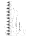
- FIG. 3 is a diagram showing an example of time-series data of the data processing device according to the first embodiment.
- FIG. 3 is a diagram showing change point waveform data of the data processing device according to the first embodiment.
- FIG. 3 is a diagram showing a parameter list of the data processing device according to the first embodiment.
- FIG. 4 is a diagram showing operation mode transition information of the data processing device according to the first embodiment. 4 is a flowchart illustrating an operation of an operation process of the data processing device according to the first embodiment.
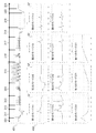
- FIG. 4 is a diagram showing an output example of a similarity time series of the data processing device according to the first embodiment.
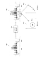
- FIG. 4 is a diagram illustrating the concept of an abnormality determination process and a deterioration determination process by a determination unit of the data processing device according to the first embodiment.
- FIG. 9 is a block diagram showing a configuration of a data processing device according to a second embodiment.
- FIG. 14 is an explanatory diagram showing a processing operation of a GUI of the data processing device according to the second embodiment.
- 9 is a flowchart illustrating an operation of an extraction condition input unit of the data processing device according to the second embodiment.
- FIG. 1 is a block diagram showing a configuration of the data processing device 100 according to the first embodiment.
- the data processing device 100 includes an extraction condition input unit 101, an extraction condition storage unit 102, a time-series data input unit 103, a segment extraction unit 104, a determination unit 109, and a determination result output unit 110.
- the segment extraction unit 104 includes a similarity calculation unit 105, a change point detection unit 106, a driving mode determination unit 107, and an information output unit 108.
- the extraction condition input unit 101 and the extraction condition storage unit 102 have a configuration for performing a preparation process before the data processing device 100 starts the detection process.
- the time-series data input unit 103, the segment extraction unit 104, the determination unit 109, and the determination result output unit 110 when receiving the input of the time-series data, perform a partial sequence (hereinafter, referred to as segment This is a configuration for performing an operation process of extracting abnormalities and deterioration of a device to be analyzed.
- the extraction condition input unit 101 receives an input of a segment extraction condition.
- the extraction condition input unit 101 causes the extraction condition storage unit 102 to store the received segment extraction conditions.
- the segment extraction condition includes change point waveform data (waveform data), a parameter list (parameter information), and operation mode transition information (transition information of equipment). Details of the segment extraction conditions described above will be described later.
- the extraction condition storage unit 102 is a storage area for storing segment extraction conditions.
- the time-series data input unit 103 receives an input of time-series data of a device to be analyzed.
- the time-series data input unit 103 outputs the received time-series data to the similarity calculation unit 105 of the segment extraction unit 104.
- the time series data is a sequence of values obtained by sequentially observing the device to be analyzed as time elapses.
- the time series data of the device to be analyzed will be described as an example, but the time series data may be of any type.
- the data may be time-series data accumulated in a control system for controlling a process of a power plant such as a thermal power plant, a hydroelectric power plant or a nuclear power plant, a chemical plant, a steel plant or a water and sewage plant.
- the time series data may be accumulated in a control system such as air conditioning, electricity, lighting, and water supply / drainage of a facility (for example, a building or a factory).
- the time-series data may be accumulated in a device on a factory line, a device mounted on an automobile, or a device mounted on a railway vehicle. Further, the data may be time-series data stored in an information system related to economy or management. A specific example of the time-series data will be described later.
- the segment extraction unit 104 extracts a segment from the time-series data received by the time-series data input unit 103 according to the segment extraction conditions stored in the extraction condition storage unit 102. Specifically, the similarity calculation unit 105 calculates the similarity at each time with respect to the input time-series data and the waveform data of each change point stored in the extraction condition storage unit 102. The similarity calculation unit 105 outputs the time series data and the calculated similarity to the change point detection unit 106. The change point detection unit 106 detects a change point of the state of the time-series data based on the input similarity. The change point detection unit 106 outputs information on the detected change point and information on the operation mode of the device to the information output unit 108.
- the operation mode determination unit 107 refers to the operation mode transition information stored in the extraction condition storage unit 102, and sets the current operation mode of the device and the next operation mode to which transition from the current operation mode is possible. Note that the operation mode determination unit 107 may set a plurality of the following operation modes.
- the change point detection unit 106 detects a change point based on the current operation mode of the device set by the operation mode determination unit 107 and the next operation mode of the device.
- the information output unit 108 sets the current operation mode, the start time of the segment, and the end time of the segment as segment information. Output to the determination unit 109.
- the determination unit 109 analyzes the input segment information, and determines an abnormality of the device or a deterioration of the device based on the degree of deviation of the data or the tendency of the data.
- the determination unit 109 outputs the determination result to the determination result output unit 110.
- the determination result output unit 110 outputs the input determination result to the outside.
- 2A and 2B are diagrams illustrating an example of a hardware configuration of the data processing device 100.
- the extraction condition input unit 101, the time series data input unit 103, the similarity calculation unit 105, the change point detection unit 106, the operation mode determination unit 107, the information output unit 108, the determination unit 109, and the determination result output unit 110 in the data processing device 100 Are realized by the processing circuit. That is, the data processing device 100 includes a processing circuit for realizing each of the above functions.
- the processing circuit may be a processing circuit 100a that is dedicated hardware as shown in FIG. 2A, or a processor 100b that executes a program stored in a memory 100c as shown in FIG. 2B. Good.
- the extraction condition input unit 101 As shown in FIG. 2A, the extraction condition input unit 101, the time-series data input unit 103, the similarity calculation unit 105, the change point detection unit 106, the driving mode determination unit 107, the information output unit 108, the determination unit 109, and the determination result output
- the processing circuit 100a includes, for example, a single circuit, a composite circuit, a programmed processor, a parallel programmed processor, an ASIC (Application Specific Integrated Circuit), and an FPGA (Field-programmable Gate). Array), or a combination of these.
- Function of each part of extraction condition input unit 101, time series data input unit 103, similarity calculation unit 105, change point detection unit 106, driving mode determination unit 107, information output unit 108, determination unit 109, and determination result output unit 110 May be realized by a processing circuit, or the functions of the respective units may be collectively realized by a single processing circuit.
- the extraction condition input unit 101 As shown in FIG. 2B, the extraction condition input unit 101, the time-series data input unit 103, the similarity calculation unit 105, the change point detection unit 106, the driving mode determination unit 107, the information output unit 108, the determination unit 109, and the determination result output
- the unit 110 is the processor 100b
- the function of each unit is realized by software, firmware, or a combination of software and firmware.
- Software or firmware is described as a program and stored in the memory 100c.
- the processor 100b reads out and executes the program stored in the memory 100c, so that the extraction condition input unit 101, the time series data input unit 103, the similarity calculation unit 105, the change point detection unit 106, the operation mode determination unit 107, The functions of the information output unit 108, the determination unit 109, and the determination result output unit 110 are realized. That is, the extraction condition input unit 101, the time series data input unit 103, the similarity calculation unit 105, the change point detection unit 106, the driving mode determination unit 107, the information output unit 108, the determination unit 109, and the determination result output unit 110 A memory 100c for storing a program that results in execution of each step shown in FIG. 7 described below when executed by 100b.
- These programs include an extraction condition input unit 101, a time series data input unit 103, a similarity calculation unit 105, a change point detection unit 106, a driving mode determination unit 107, an information output unit 108, a determination unit 109, and a determination result output. It can also be said that the computer executes the procedure or method of the unit 110.
- the processor 100b is, for example, a CPU (Central Processing Unit), a processing device, an arithmetic device, a processor, a microprocessor, a microcomputer, a DSP (Digital Signal Processor), or the like.
- the memory 100c may be a nonvolatile or volatile semiconductor memory such as a RAM (Random Access Memory), a ROM (Read Only Memory), a flash memory, an EPROM (Erasable Programmable ROM), and an EEPROM (Electrically EPROM).
- it may be a magnetic disk such as a hard disk or a flexible disk, or an optical disk such as a mini disk, a CD (Compact Disc), or a DVD (Digital Versatile Disc).
- Each function of the extraction condition input unit 101, the time series data input unit 103, the similarity calculation unit 105, the change point detection unit 106, the driving mode determination unit 107, the information output unit 108, the determination unit 109, and the determination result output unit 110 May be realized partly by dedicated hardware, and partly by software or firmware.
- the processing circuit in the data processing device 100 can realize each of the above-described functions by hardware, software, firmware, or a combination thereof.
- FIG. 3 is a diagram showing an example of time-series data of the data processing device 100 according to the first embodiment.
- a production line for a product of small-quantity multi-product production a plurality of types of products having different specifications are produced on the same production line.
- the product manufacturing procedure includes a plurality of steps, and the device for manufacturing the product switches its operation according to the recipe.
- Data measured by a sensor installed in equipment used in the production line shows a characteristic waveform for each process.
- the time-series data of the data measured by the sensor installed in the device has the following two-layer structure.
- First tier product patterns corresponding to each product lot (first lot 301, second lot 302, third lot 303 in FIG. 3)
- Second layer process pattern corresponding to the process (first process 311 to eleventh process 321 in FIG. 3)
- An idling period 331 exists between the first lot 301 and the second lot 302, and an idling period 332 exists between the second lot 302 and the third lot 303.
- FIG. 3 shows the idling 332 as an eleventh step 321.
- Each process described above corresponds to each operation mode.
- the determination unit 109 In order for the determination unit 109 to accurately detect, for example, a device abnormality or device deterioration from the time-series data shown in FIG. 3, the time-series data is divided into segments corresponding to each operation mode and compared. Is valid.
- the segment extraction condition includes change point waveform data (FIG. 4), a parameter list (FIG. 5), and operation mode transition information (FIG. 6).
- the basic idea of segment extraction is to register a waveform of a change point of a segment as a condition and determine that the operation mode has been switched when a pattern similar to the change point appears on the time-series data. By judging the switching of the operation mode on the condition of the waveform of the change point, the segment can be extracted by focusing on only the change point even in the case of the operation mode in which the duration is variable. Also, even when a pattern different from the normal pattern temporarily appears due to a device abnormality or the like in the middle of a segment, it can be determined only at the change point, and the segment is not affected by the device abnormality or the like. Can be extracted.
- FIG. 4 is a diagram showing change point waveform data of the data processing device 100 according to the first embodiment.
- the waveform data at the change point is selected from the data in a healthy state immediately after the maintenance of the device and at the time when the device starts to operate stably.
- the time series data 401 of the first lot 301 selected from FIG. 3 is selected.
- a change point of each step is detected from the time series data 401, and waveform data 402 of the detected change point is selected.
- the waveform data 402 at the change point becomes the waveform data of each operation mode.
- the waveform data labeled as the first operation mode means "pattern when changing from the eleventh operation mode to the first operation mode". Note that the waveform data of the change point may be selected for a plurality of lots.
- FIG. 5 is a diagram showing a parameter list of the data processing device 100 according to the first embodiment.
- the parameter list contains the following elements: -Operation mode 501: Information indicating the corresponding operation mode-Number of change point waveforms 502: Information indicating the number of waveform data at the change point (may be omitted if the number of waveform data can be fixed)
- a change point waveform length 503 information indicating the length of the change point waveform (may be omitted from the change point waveform data because it can be determined).
- -Distance index 504 information indicating an index of similarity (may be omitted if the default value is clear)
- -Threshold 505 of similarity Information indicating the threshold of similarity (when the similarity exceeds the threshold 505, it is determined to be a change point of the operation mode)
- Normalization method 506 Information indicating normalization (may be omitted if the default value is clear) The details of the normalization method 506 will be described later.
- FIG. 6 is a diagram illustrating operation mode transition information of the data processing device 100 according to the first embodiment.
- the operation mode transition information is information in which the dependence between operation modes is recorded in the form of an adjacent matrix.
- the first row of the table shown in FIG. 6 represents identification information of the previous operation mode, and the first column represents identification information of the next operation mode.
- “1” shown in the second row and the third column means “the second operation mode is next to the first operation mode”.
- the description of “*” in the table means that it is the first operation mode.
- the first operation mode is, for example, the first operation mode immediately after the idling periods 331 and 332 in the time-series data illustrated in FIG.
- FIG. 6 shows an example in which the operation mode transition information is recorded in the form of an adjacency matrix, but the format is not limited as long as the same information can be recorded. When there is only one type of operation mode dependency, the operation mode transition information may not be provided.
- the time-series data is a sequence of real numbers having an order represented by the following equation (1).
- T t 1 , t 2 ,..., T i (1)
- t i (1 ⁇ i ⁇ n) is the observation value at time i.
- n is the length of the time series data.
- a partial sequence obtained by cutting out a part of the time-series data is represented by the following equation (2).
- T i, w t i, t i + 1, ⁇ , t i + w-1 (2)
- w represents the length of the subsequence.
- the Euclidean distance When the Euclidean distance is applied as an index of the similarity, the closer the value is to “0”, the more similar the two waveforms are (the higher the similarity), and the larger the value, the more the two waveforms are separated. (Similarity is low).
- DTW Dynamic Time Warping
- a correlation coefficient may be used as an index of the similarity.
- Equation (5) is min-max normalization for converting the range of the subsequence from 0 to 1.
- Expression (6) is a z-normalization that performs a conversion in which the value range of the subsequence is 0 on average and 1 standard deviation.
- Equation (7) is level normalization that performs conversion that sets the average of subsequences to zero.
- the time series data obtained by normalizing the time series data T is denoted as TN .
- the function min, the function max, the function mean, and the function std represent the minimum value, the maximum value, the average value, and the standard deviation of Ti , w , respectively.
- min-max normalization shown in equation (5) or z shown in equation (6) When the normalization (6) is applied, the ability to detect a change point is high.
- the level normalization shown in Expression (7) is applied. High ability to detect change points.
- FIG. 7 is a flowchart showing the operation of the operation processing of the data processing device 100 according to the first embodiment.
- the time-series data input unit 103 receives the input and collectively processes the time-series data for a preset period.
- the time-series data input unit 103 receives an input of the time-series data (length: n) from which the segment is to be extracted (step ST1).
- the time-series data input unit 103 outputs the received time-series data to the similarity calculation unit 105. Subsequent steps are executed in accordance with the conditions stored in the extraction condition storage unit 102.
- the similarity calculation unit 105 refers to the input time-series data and the waveform data of each change point stored in the extraction condition storage unit 102, and determines the similarity between the time-series data at each time and the waveform data of the change point.
- the degree is calculated (step ST2).
- the operation mode determination unit 107 accepts the input of the current operation mode together with the input of the extraction condition input unit 101 or the time-series data input unit 103 and sets the input to the initial value. (Step ST3). For example, if the time-series data for segment extraction starts from the idle state of the device, the 11th operation mode shown in FIG. 4 is set as the current operation mode. Further, the first operation mode may always be set as a default value.
- the operation mode determination unit 107 refers to the operation mode transition information stored in the extraction condition storage unit 102, and sets the next operation mode to an operation mode that can transition from the current operation mode (step ST4). .
- the operation mode transition information shown in FIG. 6 if the current operation mode is the eleventh operation mode, the first operation mode is set as the next operation mode. As the next operation mode, a plurality of operation modes may be set.
- the operation mode determination unit 107 outputs the set next operation mode to the change point detection unit 106.
- Change point detection section 106 searches for a change point of the next input operation mode (step ST5).
- the change point detection unit 106 determines whether a change point has been detected (step ST6). If no change point is detected (step ST6; NO), the change point detection unit 106 ends the processing. Depending on the target device, an unusual behavior may appear in the time-series data due to predetermined maintenance even during stable operation. Therefore, when the change point is not detected, the operation mode determination unit 107 sets the next operation mode again as the first operation mode (the first operation mode in the example of FIG. 6) and restarts from the process of step ST5. It may be.
- step ST6 when a change point is detected (step ST6; YES), the change point detection unit 106 outputs the current operation mode, the segment start time, and the segment end time to the information output unit 108 (step ST7).
- the mode determination unit 107 is notified that a change point has been detected (step ST8).
- the information output unit 108 outputs a set of the current operation mode, the start time of the segment, and the end time of the segment to the determination unit 109 as the segment information (step ST9).
- the operation mode determination unit 107 sets the next operation mode set in step ST4 to the current operation mode based on the notification indicating that the change point has been detected (step ST10). Thereafter, the flowchart returns to the process of step ST4, and repeats the above-described process.
- the similarity calculation unit 105 reads the waveform data Q k of the change point of each operation mode k and the length w k of the waveform data of the change point (the length 503 of the change point waveform shown in FIG. 5) from the extraction condition storage unit 102. ), A similarity index (distance index 504 shown in FIG. 5) and a normalization method (normalization method shown in FIG. 5).
- the time i is changed from 1 to n ⁇ w k +1 to obtain a similarity time series S k .
- S k i dist (T i , wk, Q k) (8)
- FIG. 8 is a diagram illustrating an output example of the similarity time series of the data processing apparatus 100 according to the first embodiment.
- the similarity time series S 1 calculated from the first waveform data Q 1 to the fourth waveform data Q 4 at the changing points from the first operation mode to the fourth operation mode shown in FIG. shows an output example of the similarity time series S 4 from.
- the calculated similarity time series takes a minimum value at a change point of the operation mode.
- the change point detection unit 106 searches from the start time start of the similarity time series S k of the next operation mode k, and finds that the first change point, that is, S k is the minimum value, and the similarity threshold (see FIG. 5).
- a time j which is equal to or less than the similarity threshold 505) is set as the end time end of the current segment.
- the similarity index (the distance index 504 shown in FIG. 5) is DTW
- the minimum value may be selected in the same manner, and in the case of the correlation coefficient, the maximum value may be selected.
- step ST6 when the time j is set to the end time end of the current segment, in the process of step ST6, [eleventh operation mode, start time start "1", end time end "j"] as segment information. Is output.
- the current operation mode is set to the first operation mode, and "j + 1" is set to the segment start time start in order to restart the search from the time following the time j.
- FIG. 9 is a diagram illustrating the concept of the abnormality determination process and the deterioration determination process by the determination unit 109 of the data processing device 100 according to the first embodiment.
- the segment information 902 is extracted by the segment extraction unit 104.
- FIG. 9 shows an example of segment extraction in the fifth operation mode.
- the abnormality determination process 903 determines an abnormality based on a degree of deviation of data in a corresponding operation mode from a normal range of data.
- the determination unit 109 determines the segment value or the range of the feature amount of the segment during the period when the device is operating normally and stably (for example, one week after maintenance or until 100 lots of products are produced).
- the determining unit 109 determines that the device is abnormal.
- the deterioration determination processing 904 determines the deterioration of the device from the tendency of the data of the segment.
- the determination unit 109 plots the value of the segment or the feature amount of the segment for each product lot in chronological order, and determines that the device has deteriorated if the deviation increases as time elapses.
- the abnormality determination result and the deterioration determination result by the determination unit 109 are output to the outside via the determination result output unit 110.
- the segment extraction unit 104 may not be able to correctly extract the segment due to the influence of the abnormality and the signs of deterioration included in the time series data. In that case, the segment extraction unit 104 extracts segments that have a dependency relationship with the time-series data of the abnormality determination target and the deterioration determination target and are not affected by the device abnormality and deterioration. Further, the segment extraction unit 104 may be configured to apply the extracted segment information to the time-series data of the abnormality determination target and the deterioration determination target to extract a segment.
- the segment extraction unit 104 Segment extraction using time series data of pressure.
- the segment extracting unit 104 cuts out a torque segment using the extracted segment information, and determines abnormality of the device and deterioration of the device.
- the change point waveform data of the operation mode is newly selected from the data when the device is stably operated after the maintenance, and the parameters shown in FIG. Only by storing the data in the unit 102, the segment can be extracted.
- time-series data may be sequentially processed using the same configuration.
- time-series data is input to the time-series data input unit 103 for each observation sampling cycle.
- the similarity calculation unit 105 adds the similarity between T j ⁇ wk + 1, wk and Q k to the similarity time series S k .
- the change point detection unit 106 may search for a time corresponding to the change point between the segment start time start and the time j ⁇ wk + 1.
- the extraction condition input unit 101 that receives the input of the waveform data including the change point of the device state, the parameter information of the waveform data, and the transition information of the device, Data, a similarity calculation unit 105 for calculating the similarity between the waveform data, an operation mode determination unit 107 for setting the state of the device based on the transition information of the device, the calculated similarity, and the determined similarity.
- a change point detecting unit 106 that detects a change point from the time-series data of the device based on the state of the device, and sets a segment start time and a segment end time, which are subsequences of the time-series data; , And an information output unit 108 that outputs a segment start time and a segment end time as segment information.
- similarity calculation section 105 determines similarity by using the Eugrid distance between a partial sequence cut out from time-series data and time-series data having the same length as the partial sequence. Since the configuration is such that the degree is calculated, it is possible to generate highly accurate segment information, and it is possible to accurately determine a device abnormality, a device deterioration, or the like.
- the change point detecting unit 106 determines the minimum similarity and the similarity from the similarity time series composed of the similarities calculated by the similarity calculating unit 105 for each time of the time series data. Since the time at which the degree is equal to or less than the predetermined threshold is detected as a change point, the degree of similarity can be accurately determined.
- FIG. 10 is a block diagram illustrating a configuration of a data processing device 100A according to the second embodiment.
- the data processing device 100A according to the second embodiment includes an extraction condition input unit 101a in which the segment extraction unit 104a of the data processing device 100 described in the first embodiment has a new GUI 111 and is replaced with the extraction condition input unit 101. Make up.
- portions that are the same as or correspond to the components of the data processing device 100 according to the first embodiment are denoted by the same reference numerals as those used in the first embodiment, and descriptions thereof are omitted or simplified. .
- the segment extraction unit 104a includes the GUI 111 described below to reduce the load of the preparation process before starting the detection process.
- the GUI 111 receives the input of the time-series data from the time-series data input unit 103 and performs control to display the time-series data 1001 during a period in which the device is operating normally and stably on a display device (not shown) such as a display.
- the GUI 111 performs control for enlarging time-series data in a time-series range designated by a user with respect to the displayed time-series data and displaying the enlarged time-series data on a display device.
- the extraction condition input 101a causes the extraction condition storage unit 102 to store the waveform data of the change point selected by the user and the segment extraction condition of the waveform data.
- the GUI 111 and the extraction condition input unit 101a in the data processing device 100A are the processing circuit 100a illustrated in FIG. 2A or the processor 100b that executes a program stored in the memory 100c illustrated in FIG. 2B.
- FIG. 11 is an explanatory diagram illustrating a processing operation of the GUI 111 of the data processing device 100A according to the second embodiment.
- the GUI 111 displays, on a display device such as a display, time-series data 1001 during a period when the device is operating normally and stably.
- the user selects a range 1002 of time-series data corresponding to one lot of a product from an appearance pattern of a waveform of the displayed time-series data 1001 using an input device (not shown) such as a mouse.
- the GUI 111 performs control for enlarging the time-series data 1003 in the range 1002 selected by the user and displaying the data on the display device.
- the user specifies a change point of the operation mode from the enlarged and displayed time-series data 1003, and selects a range 1004 including the change point using the input device.
- the GUI 111 performs control to enlarge and display the waveform data 1005 in the range 1004 including the selected change point.
- the user checks the enlarged and displayed waveform data 1005, and if there is no problem with the waveform data 1005, performs an operation for attaching an operation mode label and registering the label as an extraction condition.
- the extraction condition input unit 101a causes the extraction condition storage unit 102 to store the segment extraction condition.
- FIG. 12 is a flowchart showing the operation of the extraction condition input unit 101a of the data processing device 100A according to the second embodiment.
- the extraction condition input 101 stores the waveform data (waveform data 1005 in FIG. 11) of the selected change point in the extraction condition storage. It is stored in the unit 102 (step ST22).
- the extraction condition input 101 refers to the parameter list (for example, FIG. 5) stored in the extraction condition storage unit 102, and determines whether there is an entry of the operation mode corresponding to the operation mode 501 (step ST23). . If there is no operation mode entry corresponding to the operation mode 501 (step ST23; NO), the extraction condition input 101 newly creates the corresponding operation mode 501 (step ST24). Further, the extraction condition input unit 101a sets “1” to the number 502 of transition point waveforms in the newly created operation mode 501, and sets the data length of the transition point waveform data selected as the transition point waveform length 503. Is set (step ST25).
- step ST23 when the entry of the operation mode corresponding to the operation mode 501 exists (step ST23; YES), the extraction condition input unit 101a adds “1” to the number 502 of the change point waveforms of the operation mode 501, and The data length of the selected transition point waveform data is added to the transition point waveform length 503 (step ST26).
- step ST25 or ST26 When the process of step ST25 or ST26 is completed, the process returns to step ST21, and the above process is repeated.
- step ST26 When adding the data length of the selected transition point waveform data to the transition point waveform length 503 in step ST26 described above, for example, a plurality of data lengths are stored as a list in the transition point waveform length 503 of FIG. Is done.
- the GUI 111 that receives the selection of the display range with respect to the time-series data of the device and performs control for enlarging and displaying a partial row of the selected display range is provided.
- the configuration 101 sets the waveform data and the parameter information of the sub-sequence in the selected range, so that the load of the preparation processing before the data processing apparatus starts the detection processing can be reduced.
- the present invention may include, in the scope of the present invention, a free combination of the embodiments, a modification of an arbitrary component of each embodiment, or an omission of an arbitrary component in each embodiment. It is possible.
- the data processing device according to the present invention is applied to a control system for controlling a process using time-series data of devices.
- 100, 100A ⁇ data processing device 101, 101a ⁇ extraction condition input unit, 102 # extraction condition storage unit, 103 # time series data input unit, 104, 104a ⁇ segment extraction unit, 105 ⁇ similarity calculation unit, 106 # change point detection unit, 107 # operation mode Judgment unit, 108 # information output unit, 109 # judgment unit, 110 # judgment result output unit, 111 # GUI.
Landscapes
- Engineering & Computer Science (AREA)
- Physics & Mathematics (AREA)
- General Physics & Mathematics (AREA)
- Theoretical Computer Science (AREA)
- Mathematical Physics (AREA)
- General Engineering & Computer Science (AREA)
- Automation & Control Theory (AREA)
- Quality & Reliability (AREA)
- Data Mining & Analysis (AREA)
- Pure & Applied Mathematics (AREA)
- Computing Systems (AREA)
- Computational Mathematics (AREA)
- Mathematical Analysis (AREA)
- Mathematical Optimization (AREA)
- Evolutionary Computation (AREA)
- Artificial Intelligence (AREA)
- Evolutionary Biology (AREA)
- Probability & Statistics with Applications (AREA)
- Algebra (AREA)
- Databases & Information Systems (AREA)
- Software Systems (AREA)
- Operations Research (AREA)
- Bioinformatics & Computational Biology (AREA)
- Bioinformatics & Cheminformatics (AREA)
- Life Sciences & Earth Sciences (AREA)
- Testing And Monitoring For Control Systems (AREA)
- Debugging And Monitoring (AREA)
Abstract
Description
同様に、経済または経営等に関する情報システムにおいても、株価または売上等の値を時間の経過に従い記録した時系列データが、蓄積されている。
実施の形態1.
図1は、実施の形態1に係るデータ処理装置100の構成を示すブロック図である。
データ処理装置100は、抽出条件入力部101、抽出条件記憶部102、時系列データ入力部103、セグメント抽出部104、判定部109および判定結果出力部110を備える。また、セグメント抽出部104は、類似度算出部105、変化点検出部106、運転モード判定部107および情報出力部108で構成される。
具体的に、類似度算出部105は、入力された時系列データと、抽出条件記憶部102に記憶された各変化点の波形データに対して、各時刻の類似度を算出する。類似度算出部105は、時系列データと、算出した類似度とを変化点検出部106に出力する。変化点検出部106は、入力された類似度に基づいて、時系列データの状態の変化点を検出する。変化点検出部106は、検出した変化点の情報と、機器の運転モードの情報とを情報出力部108に出力する。
図2Aおよび図2Bは、データ処理装置100のハードウェア構成例を示す図である。
データ処理装置100における抽出条件入力部101、時系列データ入力部103、類似度算出部105、変化点検出部106、運転モード判定部107、情報出力部108、判定部109および判定結果出力部110の各機能は、処理回路により実現される。即ち、データ処理装置100は、上記各機能を実現するための処理回路を備える。当該処理回路は、図2Aに示すように専用のハードウェアである処理回路100aであってもよいし、図2Bに示すようにメモリ100cに格納されているプログラムを実行するプロセッサ100bであってもよい。
メモリ100cは、例えば、RAM(Random Access Memory)、ROM(Read Only Memory)、フラッシュメモリ、EPROM(Erasable Programmable ROM)、EEPROM(Electrically EPROM)等の不揮発性または揮発性の半導体メモリであってもよいし、ハードディスク、フレキシブルディスク等の磁気ディスクであってもよいし、ミニディスク、CD(Compact Disc)、DVD(Digital Versatile Disc)等の光ディスクであってもよい。
図3は、実施の形態1に係るデータ処理装置100の時系列データの一例を示す図である。
少量多品種生産の製品の製造ラインでは、同じ製造ラインで仕様が異なる複数種類の製品が生産される。製品の製造手順は複数の工程から構成されており、製品を製造するための機器はレシピに従って動作を切り替える。当該製造ラインで使用される機器に設置されたセンサで計測されるデータは工程毎に特徴的な波形を示す。製造手順が変化すると、波形そのもの、工程毎の波形の継続時間および出現順序等が変化する。機器に設置されたセンサで計測されるデータの時系列データは、以下に示す2階層の構造を持つ。
第2階層:工程に対応した工程パターン(図3における第1工程311から第11工程321)
第1のロット301と第2のロット302との間にアイドリング期間331が存在し、第2のロット302と第3のロット303との間にアイドリング期間332が存在する。図3ではアイドリング332を第11工程321として示している。
上述した各工程が、各運転モードに対応する。判定部109において、例えば図3で示した時系列データから機器の異常または機器の劣化等を精度よく検出するためには、時系列データを各運転モードに対応したセグメントに分割して比較することが有効である。
セグメント抽出条件は、変化点波形データ(図4)、パラメータリスト(図5)、運転モード遷移情報(図6)からなる。
セグメント抽出の基本的な考え方は、セグメントの変化点の波形を条件として登録しておき、時系列データ上に当該変化点と類似したパターンが出現した場合に、運転モードが切り替わったと判断する。変化点の波形を条件として運転モードの切り替わりを判断することにより、継続時間が可変な運転モードの場合にも変化点のみに着目し、セグメントを抽出することができる。また、セグメントの途中で、機器の異常等の要因により通常とは異なるパターンが一時的に出現した場合でも、変化点のみで判断することができ、機器の異常等の影響を受けることなく、セグメントを抽出することができる。
変化点の波形データは、機器のメンテナンスが行われた直後の健全な状態であって、当該機器が安定して稼動し始めた時期のデータから選択する。図4の例では、図3から選択した第1のロット301の時系列データ401を選択する。当該時系列データ401の中から各工程の変化点を検出し、検出した変化点の波形データ402を選択する。上述したが、各工程は運転モードに対応することから、変化点の波形データ402は、各運転モードの波形データとなる。図4で示した波形データ402のうち、第1の運転モードとラベル付けされた波形データは、「第11の運転モードから第1の運転モードに変化するときのパターン」を意味している。なお、変化点の波形データは、複数ロット分を選択してもよい。
パラメータリストは以下の要素を含む。
・運転モード501:対応する運転モードを示す情報
・変化点波形の数502:変化点の波形データの数を示す情報(波形データの数が固定可能な場合は省略してもよい)
・変化点波形の長さ503:変化点の波形の長さを示す情報(変化点の波形データから判断可能なため、省略してもよい)。
・距離指標504:類似度の指標を示す情報(既定値が明らかな場合は省略してもよい)
・類似度の閾値505:類似度の閾値を示す情報(類似度が、当該閾値505を越えている場合に運転モードの変化点と判断する)
・正規化方法506:正規化を示す情報である(既定値が明らかな場合は省略してもよい)
なお、正規化方法506の詳細については後述する。
運転モード遷移情報は、運転モード間の依存関係を隣接行列の形式で記録した情報である。図6で示した表の1行目は前の運転モードの識別情報、1列目は次の運転モードの識別情報を表す。例えば、2行3列目に示した「1」は「第1運転モードの次は、第2運転モード」であることを意味している。
また、表中の「※」との記載は、最初の運転モードであることを意味している。最初の運転モードとは、例えば図3で示した時系列データにおいて、アイドリング期間331,332の直後の最初の運転モードである。一方、表中に値が示されていない要素は、該当する運転モード間に直接の依存関係がないことを意味している。図6では運転モード遷移情報を隣接行列の形式で記録した場合を例に示したが、同様の情報を記録可能であれば形式は問わない。また、運転モードの依存関係が1種類のみの場合は、運転モード遷移情報を備えていなくてもよい。
まず、時系列データは、以下の式(1)で示す順序がある実数値の列である。
T = t1, t2,・・・, ti (1)
上述した式(1)において、ti(1≦i≦n)は時刻iの観測値である。nは時系列データの長さである。
Ti,w = ti, ti+1,・・・, ti+w-1 (2)
上述した式(2)において、1≦i≦(n-w+1)である。wは部分列の長さを表す。
Q = q1, q2, ・・・, qw (3)

ユークリッド距離の他にも、マンハッタン距離、時間方向の伸縮を許容する場合には、類似度の指標としてDTW(Dynamic Time Warping:動的時間伸縮)も適用可能である。また、変化傾向の類似性で判断する場合は、類似度の指標として相関係数を利用してもよい。なお、以下では、類似度の指標としてユークリッド距離を適用した場合を例に説明する。
変化点の波形データの選択は、変化点の前後の特徴を捉えられるように選択することが望ましい。例えば、図4で示した変化点波形データにおいて、第1運転モードの変化点の波形データでは、実際の変化点がX=840の時点である。当該変化点(X=840)の直前はほぼ一定値で推移しているため、変化点の直前の波形データを、長さ60の期間(X=780~840)で切り出している。一方、変化点(X=840)の直後は上下の変化が続くため、長さ120の期間 (X=840~960)で切り出している。このように選ぶことにより、ほぼ一定値が続いた後に、大きく急上昇、急下降し、最終的に緩やかに低下する、第1運転モードの変化点に特有の波形を切り出すことができる。
時系列データと変化点の波形データとの類似度の計算においては、何らかの正規化を適用するほうが望ましい場合がある。正規化の例を以下の式(5)から式(7)に示す。式(5)は、部分列の値域を0から1に変換するmin-max正規化である。



経験的には、第9の運転モードのように単純な波形であれば正規化をしない方が変化点の検出能力が高い。一方で、第5の運転モードのように繰り返し上下に振動していて、その振幅に揺らぎがある場合には式(5)で示したmin-max正規化、または式(6)で示したz正規化(6)を適用すると変化点の検出能力が高い。時系列データが、外気温などの外的要因の影響を受ける場合であって、且つ波形には変化がないが値域に揺らぎがある場合は、式(7)で示したレベル正規化を適用すると変化点の検出能力が高い。
図7は、実施の形態1に係るデータ処理装置100の運用処理の動作を示すフローチャートである。なお、図7では、時系列データ入力部103が入力を受け付けた時系列データを、予め設定された期間まとめて一括して処理するものとして説明する。
時系列データ入力部103は、セグメント抽出対象の時系列データ(長さ:n)の入力を受け付ける(ステップST1)。時系列データ入力部103は、受け付けた時系列データを類似度算出部105に出力する。以降のステップは、抽出条件記憶部102に記憶された条件に従って実行される。
図6で示した運転モード遷移情報の例では、現在の運転モードを第11の運転モードとすると、次の運転モードに第1の運転モードを設定する。次の運転モードとして、複数の運転モードを設定してもよい。運転モード判定部107は、設定した次の運転モードを変化点検出部106に出力する。
まず、上述したステップST2で示した処理の詳細について説明する。
類似度算出部105は、抽出条件記憶部102から、各運転モードkの変化点の波形データQk、変化点の波形データの長さwk(図5で示した変化点波形の長さ503)、類似度指標(図5で示した距離指標504)および正規化方法(図5で示した正規化方法)を取得する。次に、以下の式(8)において、時刻iを1からn-wk+1まで変化させ、類似度時系列Skを取得する。
Sk i = dist(Ti,wk, Qk) (8)
Sk i = min(Sk1 i , ・・・, Skm i) (9)
図8は、実施の形態1に係るデータ処理装置100の類似度時系列の出力例を示す図である。
図8では、図4で示した第1の運転モードから第4の運転モードの変化点の、第1の波形データQ1から第4の波形データQ4について計算した、類似度時系列S1から類似度時系列S4の出力例を示している。計算された類似度時系列は、運転モードの変化点で極小値を取る。
変化点検出部106は、次の運転モードkの類似度時系列Skの開始時刻startから探索して、最初の変化点、すなわちSkが極小値であり、類似度の閾値(図5で示した類似度の閾値505)以下である時刻jを現在のセグメントの終了時刻endに設定する。次の運転モードが複数ある場合は、最初に条件を満たした運転モードであると判断する。なお、類似度指標(図5で示した距離指標504)がDTWの場合は、同様に極小値を選択すればよいし、相関係数の場合は逆に極大値を選択すればよい。
時系列データ入力部103が時系列データ901の入力を受け付けると、セグメント抽出部104によりセグメント情報902が抽出される。なお、図9では、第5の運転モードのセグメント抽出例を示している。
異常判定処理903は、該当する運転モードにおけるデータの正常範囲からのデータの外れ度合いにより異常を判定する。まず、判定部109は、機器が正常に安定稼働している期間(例えば、メンテナンス後の1週間、または製品が100ロット生産されるまで)のセグメントの値、またはセグメントの特徴量の範囲を、該当する運転モードの正常範囲903aとして設定する。その後、判定部109は、セグメント抽出部104が抽出したセグメント情報902のセグメントの値またはセグメント特徴量が正常範囲903aから外れている場合には、機器の異常と判定する。
判定部109による異常判定結果および劣化判定結果は、判定結果出力部110を介して外部に出力される。
例えば、観測のサンプリング周期毎に、時系列データ入力部103に時系列データの入力があるとする。時刻jのデータが入力された時、類似度算出部105は、類似度時系列SkにTj-wk+1,wkとQkとの類似度を追加する。変化点検出部106は、セグメントの開始時刻startと時刻j-wk+1の間で、変化点に該当する時刻を探索すればよい。
この実施の形態2では、GUI(Graphical User Interface)を備える構成を示す。 図10は、実施の形態2に係るデータ処理装置100Aの構成を示すブロック図である。
実施の形態2のデータ処理装置100Aは、実施の形態1で示したデータ処理装置100のセグメント抽出部104aがGUI111を新たに備え、抽出条件入力部101に替えた抽出条件入力部101aを備えて構成している。なお、以下では、実施の形態1に係るデータ処理装置100の構成要素と同一または相当する部分には、実施の形態1で使用した符号と同一の符号を付して説明を省略または簡略化する。
データ処理装置100AにおけるGUI111および抽出条件入力部101aは、図2Aで示した処理回路100a、または図2Bで示したメモリ100cに格納されるプログラムを実行するプロセッサ100bである。
図11は、実施の形態2に係るデータ処理装置100AのGUI111の処理動作を示す説明図である。
GUI111は、機器が正常に安定稼働している期間の時系列データ1001をディスプレイ等の表示装置に表示する。ユーザは、表示された時系列データ1001の波形の出現パターン等から、製品1ロット分に相当する時系列データの範囲1002を、マウス等の入力装置(図示しない)を用いて選択する。GUI111は、ユーザによって選択された範囲1002の時系列データ1003を拡大して表示装置に表示させる制御を行う。
図12は、実施の形態2に係るデータ処理装置100Aの抽出条件入力部101aの動作を示すフローチャートである。
抽出条件入力101は、運転モードのラベルが付された抽出条件の登録操作が入力されると(ステップST21)、選択された変化点の波形データ(図11における波形データ1005)を、抽出条件記憶部102に記憶させる(ステップST22)。
上述したステップST26において、変化点波形の長さ503に選択された変化点の波形データのデータ長を追加する場合、例えば図5の変化点波形の長さ503に複数のデータ長がリストとして記憶される。
Claims (7)
- 機器の状態の変化点を含む波形データ、当該波形データのパラメータ情報、および前記機器の遷移情報の入力を受け付ける抽出条件入力部と、
前記機器の時系列データと、前記抽出条件入力部が受け付けた前記波形データとの類似度を算出する類似度算出部と、
前記抽出条件入力部が受け付けた前記機器の遷移情報に基づいて、前記機器の状態を設定する運転モード判定部と、
前記類似度算出部が算出した類似度、および前記運転モード判定部が判定した前記機器の状態に基づいて、前記機器の時系列データから、前記変化点を検出し、前記時系列データの部分列であるセグメントの開始時刻および前記セグメントの終了時刻を設定する変化点検出部と、
前記機器の状態、前記セグメントの開始時刻および前記セグメントの終了時刻をセグメント情報として出力する情報出力部とを備えたデータ処理装置。 - 前記情報出力部が出力した前記セグメント情報に基づいて、データの外れ度合い、またはデータの傾向を判定する判定部を備えたことを特徴とする請求項1記載のデータ処理装置。
- 前記類似度算出部は、前記時系列データから切り出した部分列と、当該部分列と同一の長さの前記時系列データとのユーグリット距離を用いて、前記類似度を算出することを特徴とする請求項1または請求項2記載のデータ処理装置。
- 前記類似度算出部は、前記時系列データから切り出した部分列と、当該部分列と同一の長さの前記時系列データとを正規化した後に、前記類似度を算出することを特徴とする請求項1または請求項2記載のデータ処理装置。
- 前記変化点検出部は、前記類似度算出部が前記時系列データの時刻毎に算出した類似度からなる類似度時系列から、前記類似度が極小値、且つ前記類似度が所定の閾値以下の時刻を、前記変化点として検出することを特徴とする請求項3または請求項4記載のデータ処理装置。
- 前記機器の時系列データに対して表示範囲の選択を受け付け、前記選択された表示範囲の部分列を拡大表示させる制御を行うGUIを備え、
前記抽出条件入力部は、前記選択された範囲の部分列の前記波形データおよび前記パラメータ情報を設定することを特徴とする請求項1または請求項2記載のデータ処理装置。 - 抽出条件入力部が、機器の状態の変化点を含む波形データ、当該波形データのパラメータ情報、および前記機器の遷移情報の入力を受け付けるステップと、
類似度算出部が、前記機器の時系列データと、前記波形データとの類似度を算出するステップと、
運転モード判定部が、前記機器の遷移情報に基づいて、前記機器の状態を設定するステップと、
変化点検出部が、前記算出された類似度、および前記設定された前記機器の状態に基づいて、前記機器の時系列データから、前記変化点を検出し、前記時系列データの部分列であるセグメントの開始時刻および前記セグメントの終了時刻を設定するステップと、
情報出力部が、前記機器の状態、前記セグメントの開始時刻および前記セグメントの終了時刻をセグメント情報として出力するステップとを備えたデータ処理方法。
Priority Applications (7)
| Application Number | Priority Date | Filing Date | Title |
|---|---|---|---|
| CN201880095139.5A CN112368683B (zh) | 2018-07-03 | 2018-07-03 | 数据处理装置以及数据处理方法 |
| DE112018007712.8T DE112018007712B4 (de) | 2018-07-03 | 2018-07-03 | Datenverarbeitungseinrichtung und datenverarbeitungsverfahren |
| PCT/JP2018/025252 WO2020008533A1 (ja) | 2018-07-03 | 2018-07-03 | データ処理装置およびデータ処理方法 |
| KR1020207036750A KR102238867B1 (ko) | 2018-07-03 | 2018-07-03 | 데이터 처리 장치 및 데이터 처리 방법 |
| JP2020528577A JP6786016B2 (ja) | 2018-07-03 | 2018-07-03 | データ処理装置およびデータ処理方法 |
| TW108110456A TWI727289B (zh) | 2018-07-03 | 2019-03-26 | 資料處理裝置及資料處理方法 |
| US17/119,222 US11294364B2 (en) | 2018-07-03 | 2020-12-11 | Data processing device and data processing method |
Applications Claiming Priority (1)
| Application Number | Priority Date | Filing Date | Title |
|---|---|---|---|
| PCT/JP2018/025252 WO2020008533A1 (ja) | 2018-07-03 | 2018-07-03 | データ処理装置およびデータ処理方法 |
Related Child Applications (1)
| Application Number | Title | Priority Date | Filing Date |
|---|---|---|---|
| US17/119,222 Continuation US11294364B2 (en) | 2018-07-03 | 2020-12-11 | Data processing device and data processing method |
Publications (1)
| Publication Number | Publication Date |
|---|---|
| WO2020008533A1 true WO2020008533A1 (ja) | 2020-01-09 |
Family
ID=69060967
Family Applications (1)
| Application Number | Title | Priority Date | Filing Date |
|---|---|---|---|
| PCT/JP2018/025252 Ceased WO2020008533A1 (ja) | 2018-07-03 | 2018-07-03 | データ処理装置およびデータ処理方法 |
Country Status (7)
| Country | Link |
|---|---|
| US (1) | US11294364B2 (ja) |
| JP (1) | JP6786016B2 (ja) |
| KR (1) | KR102238867B1 (ja) |
| CN (1) | CN112368683B (ja) |
| DE (1) | DE112018007712B4 (ja) |
| TW (1) | TWI727289B (ja) |
| WO (1) | WO2020008533A1 (ja) |
Cited By (3)
| Publication number | Priority date | Publication date | Assignee | Title |
|---|---|---|---|---|
| CN112098836A (zh) * | 2020-08-14 | 2020-12-18 | 贵州乌江水电开发有限责任公司东风发电厂 | 一种基于电气畸变分析的电动机非稳数据排除方法及系统 |
| WO2021210185A1 (ja) * | 2020-04-18 | 2021-10-21 | 三菱電機株式会社 | ロギングデータ表示プログラム、ロギングデータ表示装置およびロギングデータ表示方法 |
| KR20230010773A (ko) | 2020-07-03 | 2023-01-19 | 미쓰비시덴키 가부시키가이샤 | 데이터 처리 장치 |
Families Citing this family (4)
| Publication number | Priority date | Publication date | Assignee | Title |
|---|---|---|---|---|
| GB2580950A (en) * | 2019-01-31 | 2020-08-05 | Datalytyx Ltd | Data processing system |
| KR20210127358A (ko) * | 2020-04-14 | 2021-10-22 | 삼성에스디에스 주식회사 | 시계열 데이터의 패턴 추출 및 예측 방법 |
| EP4219138A1 (en) * | 2022-01-31 | 2023-08-02 | Ricoh Company, Ltd. | Information processing apparatus, information processing system, information processing method, and carrier medium |
| KR102867332B1 (ko) * | 2022-12-13 | 2025-10-01 | 삼성전자주식회사 | 반도체 제조용 시계열 데이터 처리 방법 및 이를 수행하기 위한 장치 |
Citations (4)
| Publication number | Priority date | Publication date | Assignee | Title |
|---|---|---|---|---|
| JP2006338373A (ja) * | 2005-06-02 | 2006-12-14 | Toshiba Corp | 多変数時系列データ分析装置、方法およびプログラム |
| JP2015075821A (ja) * | 2013-10-07 | 2015-04-20 | 横河電機株式会社 | 状態診断方法および状態診断装置 |
| WO2015159377A1 (ja) * | 2014-04-16 | 2015-10-22 | 株式会社日立製作所 | 設計支援装置 |
| WO2016117021A1 (ja) * | 2015-01-20 | 2016-07-28 | 株式会社日立製作所 | 機械診断装置および機械診断方法 |
Family Cites Families (19)
| Publication number | Priority date | Publication date | Assignee | Title |
|---|---|---|---|---|
| JPH05204991A (ja) * | 1992-01-30 | 1993-08-13 | Hitachi Ltd | 時系列データ検索方法およびこれを用いた検索システム |
| JP3483113B2 (ja) * | 1998-05-29 | 2004-01-06 | 日本電信電話株式会社 | 時系列画像検索方法、装置、および時系列画像検索プログラムを記録した記録媒体 |
| JP3995569B2 (ja) * | 2002-09-20 | 2007-10-24 | 昌一 手島 | 波形パターンデータから設備の診断・監視のための特徴を抽出する方法及びプログラム |
| JP4180960B2 (ja) | 2003-04-11 | 2008-11-12 | キヤノンItソリューションズ株式会社 | データ分析装置及びその制御方法、並びにコンピュータプログラム及びコンピュータ可読記憶媒体 |
| JP4224095B2 (ja) | 2006-09-28 | 2009-02-12 | 株式会社東芝 | 情報処理装置、情報処理プログラムおよび情報処理システム |
| CN102033486B (zh) * | 2009-09-25 | 2012-05-30 | 卡西欧计算机株式会社 | 时刻信息取得装置和电波钟表 |
| JP5277185B2 (ja) | 2010-01-26 | 2013-08-28 | 株式会社日立製作所 | 情報処理システム |
| WO2012103485A2 (en) * | 2011-01-28 | 2012-08-02 | The Board Of Regents Of The Nevada System Of Higher Education On Behalf Of The Desert Research Institute | Signal identification methods and systems |
| WO2013051101A1 (ja) | 2011-10-04 | 2013-04-11 | 株式会社日立製作所 | 時系列データ管理システム,および方法 |
| US10054933B2 (en) * | 2012-03-27 | 2018-08-21 | Sirqul, Inc. | Controlling distributed device operations |
| US10282676B2 (en) * | 2014-10-06 | 2019-05-07 | Fisher-Rosemount Systems, Inc. | Automatic signal processing-based learning in a process plant |
| TR201903636T4 (tr) * | 2014-05-01 | 2019-04-22 | Sicpa Holding Sa | Dinamik olarak konfigüre edilebilir üretim ve/veya dağıtım hattı kontrol sistemi ve buna yönelik yöntem. |
| JP2016091512A (ja) * | 2014-11-11 | 2016-05-23 | ルネサスエレクトロニクス株式会社 | 接続関係検出システム、情報処理装置、及び接続関係検出方法 |
| JP6613828B2 (ja) * | 2015-11-09 | 2019-12-04 | 富士通株式会社 | 画像処理プログラム、画像処理装置、及び画像処理方法 |
| JP6767166B2 (ja) * | 2016-05-25 | 2020-10-14 | アズビル株式会社 | 監視装置、監視方法、およびプログラム |
| US10739764B2 (en) * | 2016-07-15 | 2020-08-11 | Ricoh Company, Ltd. | Diagnostic apparatus, diagnostic system, diagnostic method, and recording medium |
| JP6532845B2 (ja) * | 2016-07-26 | 2019-06-19 | 双葉電子工業株式会社 | 計測装置、計測方法、プログラム |
| EP3279737A1 (en) * | 2016-08-05 | 2018-02-07 | ASML Netherlands B.V. | Diagnostic system for an industrial process |
| GB2553514B (en) * | 2016-08-31 | 2022-01-26 | Green Running Ltd | A utility consumption signal processing system and a method of processing a utility consumption signal |
-
2018
- 2018-07-03 JP JP2020528577A patent/JP6786016B2/ja active Active
- 2018-07-03 KR KR1020207036750A patent/KR102238867B1/ko active Active
- 2018-07-03 DE DE112018007712.8T patent/DE112018007712B4/de active Active
- 2018-07-03 WO PCT/JP2018/025252 patent/WO2020008533A1/ja not_active Ceased
- 2018-07-03 CN CN201880095139.5A patent/CN112368683B/zh active Active
-
2019
- 2019-03-26 TW TW108110456A patent/TWI727289B/zh active
-
2020
- 2020-12-11 US US17/119,222 patent/US11294364B2/en active Active
Patent Citations (4)
| Publication number | Priority date | Publication date | Assignee | Title |
|---|---|---|---|---|
| JP2006338373A (ja) * | 2005-06-02 | 2006-12-14 | Toshiba Corp | 多変数時系列データ分析装置、方法およびプログラム |
| JP2015075821A (ja) * | 2013-10-07 | 2015-04-20 | 横河電機株式会社 | 状態診断方法および状態診断装置 |
| WO2015159377A1 (ja) * | 2014-04-16 | 2015-10-22 | 株式会社日立製作所 | 設計支援装置 |
| WO2016117021A1 (ja) * | 2015-01-20 | 2016-07-28 | 株式会社日立製作所 | 機械診断装置および機械診断方法 |
Cited By (4)
| Publication number | Priority date | Publication date | Assignee | Title |
|---|---|---|---|---|
| WO2021210185A1 (ja) * | 2020-04-18 | 2021-10-21 | 三菱電機株式会社 | ロギングデータ表示プログラム、ロギングデータ表示装置およびロギングデータ表示方法 |
| KR20230010773A (ko) | 2020-07-03 | 2023-01-19 | 미쓰비시덴키 가부시키가이샤 | 데이터 처리 장치 |
| CN112098836A (zh) * | 2020-08-14 | 2020-12-18 | 贵州乌江水电开发有限责任公司东风发电厂 | 一种基于电气畸变分析的电动机非稳数据排除方法及系统 |
| CN112098836B (zh) * | 2020-08-14 | 2021-05-14 | 贵州乌江水电开发有限责任公司东风发电厂 | 一种基于电气畸变分析的电动机非稳数据排除方法及系统 |
Also Published As
| Publication number | Publication date |
|---|---|
| KR102238867B1 (ko) | 2021-04-09 |
| JPWO2020008533A1 (ja) | 2020-12-17 |
| JP6786016B2 (ja) | 2020-11-18 |
| TWI727289B (zh) | 2021-05-11 |
| CN112368683A (zh) | 2021-02-12 |
| DE112018007712T5 (de) | 2021-04-08 |
| US20210096556A1 (en) | 2021-04-01 |
| TW202006488A (zh) | 2020-02-01 |
| CN112368683B (zh) | 2024-03-26 |
| US11294364B2 (en) | 2022-04-05 |
| KR20210002748A (ko) | 2021-01-08 |
| DE112018007712B4 (de) | 2024-08-01 |
Similar Documents
| Publication | Publication Date | Title |
|---|---|---|
| JP6786016B2 (ja) | データ処理装置およびデータ処理方法 | |
| CN113168171B (zh) | 异常探测装置以及异常探测方法 | |
| CN1098512C (zh) | 冷却器压缩机电机过热的预测方法 | |
| JP7126256B2 (ja) | 異常診断装置、異常診断方法、及びプログラム | |
| EP2857917A1 (en) | State diagnosing method and state diagnosing apparatus | |
| JP6895816B2 (ja) | 異常診断装置、異常診断方法及び異常診断プログラム | |
| TWI747055B (zh) | 狀態推斷裝置以及狀態推斷方法 | |
| CN113330379B (zh) | 异常原因推定装置、异常原因推定方法及介质 | |
| CN119026002B (zh) | 一种负荷事件识别方法及系统 | |
| JP6848546B2 (ja) | 変化点検出装置および変化点検出方法 | |
| US10359401B2 (en) | Malfunction diagnosing apparatus, malfunction diagnosing method, and recording medium | |
| TWI861824B (zh) | 異常診斷方法、異常診斷裝置以及異常診斷程式 | |
| CN116258281A (zh) | 基于云平台管理的物联网消防监测及调控系统 | |
| CN118395345A (zh) | 一种涂布机多级热回收与能量监控系统 | |
| CN110163451B (zh) | 暖通系统的健康度预测方法、系统和计算机可读存储介质 | |
| EP3303835B1 (en) | Method for windmill farm monitoring | |
| JP6648747B2 (ja) | 異常原因特定方法および異常原因特定装置 | |
| JP6347771B2 (ja) | 異常診断装置、異常診断方法及び異常診断プログラム | |
| JP5817323B2 (ja) | 異常診断装置 | |
| JP6995100B2 (ja) | 情報処理装置、算出方法および算出プログラム | |
| CN118277943B (zh) | 一种电机运行状态的快速检测方法 | |
| CN120558165B (zh) | 一种用于隧道的变形监测预警方法及系统 | |
| Loss et al. | Vibration-based methods for circuit breaker monitoring and prognostics | |
| CN121638867A (zh) | 一种基于数据分析的工业物联网风险预警方法 | |
| CN120231873A (zh) | 齿轮箱润滑系统的异常识别方法和控制器 |
Legal Events
| Date | Code | Title | Description |
|---|---|---|---|
| 121 | Ep: the epo has been informed by wipo that ep was designated in this application |
Ref document number: 18925127 Country of ref document: EP Kind code of ref document: A1 |
|
| ENP | Entry into the national phase |
Ref document number: 2020528577 Country of ref document: JP Kind code of ref document: A |
|
| ENP | Entry into the national phase |
Ref document number: 20207036750 Country of ref document: KR Kind code of ref document: A |
|
| 122 | Ep: pct application non-entry in european phase |
Ref document number: 18925127 Country of ref document: EP Kind code of ref document: A1 |