WO2020005008A1 - 배터리 냉각기 - Google Patents
배터리 냉각기 Download PDFInfo
- Publication number
- WO2020005008A1 WO2020005008A1 PCT/KR2019/007882 KR2019007882W WO2020005008A1 WO 2020005008 A1 WO2020005008 A1 WO 2020005008A1 KR 2019007882 W KR2019007882 W KR 2019007882W WO 2020005008 A1 WO2020005008 A1 WO 2020005008A1
- Authority
- WO
- WIPO (PCT)
- Prior art keywords
- tube
- header
- tank component
- end portion
- heat exchanger
- Prior art date
- Legal status (The legal status is an assumption and is not a legal conclusion. Google has not performed a legal analysis and makes no representation as to the accuracy of the status listed.)
- Ceased
Links
Images


Classifications
-
- H—ELECTRICITY
- H01—ELECTRIC ELEMENTS
- H01M—PROCESSES OR MEANS, e.g. BATTERIES, FOR THE DIRECT CONVERSION OF CHEMICAL ENERGY INTO ELECTRICAL ENERGY
- H01M10/00—Secondary cells; Manufacture thereof
- H01M10/60—Heating or cooling; Temperature control
- H01M10/65—Means for temperature control structurally associated with the cells
- H01M10/655—Solid structures for heat exchange or heat conduction
- H01M10/6554—Rods or plates
-
- H—ELECTRICITY
- H01—ELECTRIC ELEMENTS
- H01M—PROCESSES OR MEANS, e.g. BATTERIES, FOR THE DIRECT CONVERSION OF CHEMICAL ENERGY INTO ELECTRICAL ENERGY
- H01M10/00—Secondary cells; Manufacture thereof
- H01M10/60—Heating or cooling; Temperature control
- H01M10/65—Means for temperature control structurally associated with the cells
- H01M10/655—Solid structures for heat exchange or heat conduction
- H01M10/6556—Solid parts with flow channel passages or pipes for heat exchange
-
- F—MECHANICAL ENGINEERING; LIGHTING; HEATING; WEAPONS; BLASTING
- F28—HEAT EXCHANGE IN GENERAL
- F28D—HEAT-EXCHANGE APPARATUS, NOT PROVIDED FOR IN ANOTHER SUBCLASS, IN WHICH THE HEAT-EXCHANGE MEDIA DO NOT COME INTO DIRECT CONTACT
- F28D1/00—Heat-exchange apparatus having stationary conduit assemblies for one heat-exchange medium only, the media being in contact with different sides of the conduit wall, in which the other heat-exchange medium is a large body of fluid, e.g. domestic or motor car radiators
- F28D1/02—Heat-exchange apparatus having stationary conduit assemblies for one heat-exchange medium only, the media being in contact with different sides of the conduit wall, in which the other heat-exchange medium is a large body of fluid, e.g. domestic or motor car radiators with heat-exchange conduits immersed in the body of fluid
- F28D1/04—Heat-exchange apparatus having stationary conduit assemblies for one heat-exchange medium only, the media being in contact with different sides of the conduit wall, in which the other heat-exchange medium is a large body of fluid, e.g. domestic or motor car radiators with heat-exchange conduits immersed in the body of fluid with tubular conduits
- F28D1/053—Heat-exchange apparatus having stationary conduit assemblies for one heat-exchange medium only, the media being in contact with different sides of the conduit wall, in which the other heat-exchange medium is a large body of fluid, e.g. domestic or motor car radiators with heat-exchange conduits immersed in the body of fluid with tubular conduits the conduits being straight
- F28D1/0535—Heat-exchange apparatus having stationary conduit assemblies for one heat-exchange medium only, the media being in contact with different sides of the conduit wall, in which the other heat-exchange medium is a large body of fluid, e.g. domestic or motor car radiators with heat-exchange conduits immersed in the body of fluid with tubular conduits the conduits being straight the conduits having a non-circular cross-section
-
- F—MECHANICAL ENGINEERING; LIGHTING; HEATING; WEAPONS; BLASTING
- F28—HEAT EXCHANGE IN GENERAL
- F28F—DETAILS OF HEAT-EXCHANGE AND HEAT-TRANSFER APPARATUS, OF GENERAL APPLICATION
- F28F1/00—Tubular elements; Assemblies of tubular elements
- F28F1/02—Tubular elements of cross-section which is non-circular
- F28F1/022—Tubular elements of cross-section which is non-circular with multiple channels
-
- F—MECHANICAL ENGINEERING; LIGHTING; HEATING; WEAPONS; BLASTING
- F28—HEAT EXCHANGE IN GENERAL
- F28F—DETAILS OF HEAT-EXCHANGE AND HEAT-TRANSFER APPARATUS, OF GENERAL APPLICATION
- F28F9/00—Casings; Header boxes; Auxiliary supports for elements; Auxiliary members within casings
- F28F9/02—Header boxes; End plates
- F28F9/0219—Arrangements for sealing end plates into casing or header box; Header box sub-elements
- F28F9/0224—Header boxes formed by sealing end plates into covers
- F28F9/0226—Header boxes formed by sealing end plates into covers with resilient gaskets
-
- F—MECHANICAL ENGINEERING; LIGHTING; HEATING; WEAPONS; BLASTING
- F28—HEAT EXCHANGE IN GENERAL
- F28F—DETAILS OF HEAT-EXCHANGE AND HEAT-TRANSFER APPARATUS, OF GENERAL APPLICATION
- F28F9/00—Casings; Header boxes; Auxiliary supports for elements; Auxiliary members within casings
- F28F9/02—Header boxes; End plates
- F28F9/04—Arrangements for sealing elements into header boxes or end plates
-
- F—MECHANICAL ENGINEERING; LIGHTING; HEATING; WEAPONS; BLASTING
- F28—HEAT EXCHANGE IN GENERAL
- F28F—DETAILS OF HEAT-EXCHANGE AND HEAT-TRANSFER APPARATUS, OF GENERAL APPLICATION
- F28F9/00—Casings; Header boxes; Auxiliary supports for elements; Auxiliary members within casings
- F28F9/02—Header boxes; End plates
- F28F9/04—Arrangements for sealing elements into header boxes or end plates
- F28F9/16—Arrangements for sealing elements into header boxes or end plates by permanent joints, e.g. by rolling
-
- H—ELECTRICITY
- H01—ELECTRIC ELEMENTS
- H01M—PROCESSES OR MEANS, e.g. BATTERIES, FOR THE DIRECT CONVERSION OF CHEMICAL ENERGY INTO ELECTRICAL ENERGY
- H01M10/00—Secondary cells; Manufacture thereof
- H01M10/60—Heating or cooling; Temperature control
- H01M10/61—Types of temperature control
- H01M10/613—Cooling or keeping cold
-
- H—ELECTRICITY
- H01—ELECTRIC ELEMENTS
- H01M—PROCESSES OR MEANS, e.g. BATTERIES, FOR THE DIRECT CONVERSION OF CHEMICAL ENERGY INTO ELECTRICAL ENERGY
- H01M10/00—Secondary cells; Manufacture thereof
- H01M10/60—Heating or cooling; Temperature control
- H01M10/62—Heating or cooling; Temperature control specially adapted for specific applications
- H01M10/625—Vehicles
-
- H—ELECTRICITY
- H01—ELECTRIC ELEMENTS
- H01M—PROCESSES OR MEANS, e.g. BATTERIES, FOR THE DIRECT CONVERSION OF CHEMICAL ENERGY INTO ELECTRICAL ENERGY
- H01M10/00—Secondary cells; Manufacture thereof
- H01M10/60—Heating or cooling; Temperature control
- H01M10/65—Means for temperature control structurally associated with the cells
- H01M10/656—Means for temperature control structurally associated with the cells characterised by the type of heat-exchange fluid
- H01M10/6567—Liquids
-
- F—MECHANICAL ENGINEERING; LIGHTING; HEATING; WEAPONS; BLASTING
- F28—HEAT EXCHANGE IN GENERAL
- F28D—HEAT-EXCHANGE APPARATUS, NOT PROVIDED FOR IN ANOTHER SUBCLASS, IN WHICH THE HEAT-EXCHANGE MEDIA DO NOT COME INTO DIRECT CONTACT
- F28D21/00—Heat-exchange apparatus not covered by any of the groups F28D1/00 - F28D20/00
- F28D2021/0019—Other heat exchangers for particular applications; Heat exchange systems not otherwise provided for
- F28D2021/0028—Other heat exchangers for particular applications; Heat exchange systems not otherwise provided for for cooling heat generating elements, e.g. for cooling electronic components or electric devices
-
- F—MECHANICAL ENGINEERING; LIGHTING; HEATING; WEAPONS; BLASTING
- F28—HEAT EXCHANGE IN GENERAL
- F28F—DETAILS OF HEAT-EXCHANGE AND HEAT-TRANSFER APPARATUS, OF GENERAL APPLICATION
- F28F2230/00—Sealing means
-
- H—ELECTRICITY
- H01—ELECTRIC ELEMENTS
- H01M—PROCESSES OR MEANS, e.g. BATTERIES, FOR THE DIRECT CONVERSION OF CHEMICAL ENERGY INTO ELECTRICAL ENERGY
- H01M2220/00—Batteries for particular applications
- H01M2220/20—Batteries in motive systems, e.g. vehicle, ship, plane
-
- Y—GENERAL TAGGING OF NEW TECHNOLOGICAL DEVELOPMENTS; GENERAL TAGGING OF CROSS-SECTIONAL TECHNOLOGIES SPANNING OVER SEVERAL SECTIONS OF THE IPC; TECHNICAL SUBJECTS COVERED BY FORMER USPC CROSS-REFERENCE ART COLLECTIONS [XRACs] AND DIGESTS
- Y02—TECHNOLOGIES OR APPLICATIONS FOR MITIGATION OR ADAPTATION AGAINST CLIMATE CHANGE
- Y02E—REDUCTION OF GREENHOUSE GAS [GHG] EMISSIONS, RELATED TO ENERGY GENERATION, TRANSMISSION OR DISTRIBUTION
- Y02E60/00—Enabling technologies; Technologies with a potential or indirect contribution to GHG emissions mitigation
- Y02E60/10—Energy storage using batteries
Definitions
- Battery coolers are generally known in the art for cooling batteries or batteries of an electric vehicle or similar device.
- the present disclosure relates to a battery cooler, such as the battery cooler described in DE 10 2018 208 473.4 using a wide extrusion tube inserted between battery cells, the tube enters the tank component, and then the tank component is connected to the tube. It is connected to the hose to provide a cooling fluid.
- Current designs of such battery coolers require a rather complicated and burdensome connection to be formed between the tank components on the one hand and the tube on the other.
- an object is to facilitate connecting a tank component to a tube.
- an object is to provide a cheaper solution compared to previous designs.
- connection between the tube and the tank component may allow the tube to be insulated, in particular electrically insulated, by a coating applied to the tube before the assembly, in particular before the connection between the tube and the tank component is effected.
- a fourth aspect of the present disclosure is to provide an alternative design and assembly method for the design and assembly method described in DE 10 2018 208 473.4.
- the tube and tank components are assembled mechanically without the use of soldering or welding during the assembly process. This process is first easier to carry out during the manufacture of the battery cooler.
- mechanical assembly which does not require soldering or welding in the actual assembly steps, allows the tube to be coated by an insulating coating (electrically or otherwise) or by any other coating that may be temperature sensitive. . That is, the mechanical assembly according to the present disclosure allows any coating to be provided to the tube or made of any material, which is potentially destroyed or damaged by high temperatures such as those experienced during soldering or welding.
- assembling the tube and tank components includes providing a tube, placing a header on the tube, and placing a gasket on the tube.
- the gasket and header are disposed on the tube in such a way that the (free) end of the tube, which is the end to be connected to the tank component by the gasket and header, is accessible for the next step of the assembly process.
- the gasket and header may be disposed on the tube via an end to be connected with the tank component, but it is of course also possible to place the gasket and header on the tube via the opposite end of the tube (if present).
- the end of the tube, to which the tube is connected to the tank component is disposed between the gasket and the header on the one hand and between the tank component on the other hand (later).
- the tube end to be connected to the tank component is expanded. This can be accomplished by expanding each tube end using a punching knife or similar object.
- the tube end can extend over the entire circumference of the tube, but it is also possible that the tube end only partially extends. Extending the tube end over its entire circumference allows for a more stable connection of the tube and the tank component.
- the amount of expansion at the tube end can be in particular 0.1 mm to 2.0 mm, especially in battery coolers for electric vehicles, since the tube expansion mentioned above on the one hand provides sufficient strength in the connection between the tube and the tank component. desirable. On the other hand, the expansion is not so large that the tube material is not damaged by the expansion, and the connection between the tube and the tank component is kept tight.
- the gasket may have a general torus shape, such as an O-ring or a modified O-ring.
- This means that the gasket may be a ring, an ellipse, a racetrack, or may be deformed in plan view and in a cross sectional view of a portion of the gasket, which may be circular, elliptical or deformed. Shape variations are possible.
- the gasket may have a circular, elliptical or racetrack shape, or even follow the contour of a polygon, in particular a rectangle.
- the above-mentioned plan view will be a view along the main extension of the tube, ie parallel to the tube central axis and onto the end to be connected to the tank component. .
- the gasket can be sized to allow the unexpanded tube to fit into the gasket (round, oval or racetrack shape).
- the tube may be tightly engaged with the gasket or may be shaped to be expanded to firmly engage with the gasket. The tube compresses the gasket outward when the gasket is moved to the tube end and the tube end is fully extended as described above.
- the tool for expanding the tube end can be removed and the tank component to be connected to the tube can be placed on the extended end of the tube.
- the gasket and header can be moved towards the tube end to contact the tank component.
- the header and tank components that ultimately cooperate to form a connection between the tube and the tank component move towards each other and finally contact each other, and the gasket is not only between the header and the tank component but also between the header and the tube component. Is placed.
- the extended end portion of the tube is surrounded by additional elements such as the header or tank component, or both and potentially a gasket.
- the gasket is compressed in the radial direction with respect to the tube axis, between the expanded tube end on the one hand and the header on the other.
- the tank component also contacts the header and the header and tank component are crimped together. Possible ways of crimping the tank component and the header together are wavy crimping or tap crimping.
- the tank component at least partially disposed on the expanded tube end is configured to have a shape that allows the tube to contact the tank component.
- the tank component may include a recess for receiving the expanded tube end, which may have a similar element or shape for contacting an inner step, a flange, or the end of the tube.
- the header may be shaped and sized to fit firmly on the unexpanded tube and to be movable along the tube axis.
- the shape and size of the header may be selected to avoid moving the expanded tube end through the header. That is, the opening of the header to receive the tube may be sized to allow the expanded end of the tube to move through the opening, while being too rigid to move through the opening.
- the gasket may also be designed to provide sufficient force to securely maintain the connection between the tank component and the tube accordingly.
- the gasket can be designed to exert a radial compressive force on the tube when the header and tank components are crimped together, such that the radial end of the tube has an extended tube end on the one hand and a tube on the other hand under real circumstances. Can be chosen high enough so that it cannot be pulled from the connection between the tank component and / or the header.
- FIG. 2 illustrates an exploded view of the elements to be assembled for the assembly of FIG. 1.
- FIG. 3 illustrates some of the elements of FIG. 2 at a stage of the assembly method.
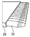
- FIG. 5 illustrates a tool for extending the tube end to connect to a tank component.
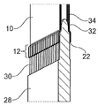
- FIG. 6 illustrates the tool also shown in FIG. 5 extending the end of the tube to be connected to the tank component.
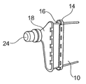
- FIG. 7 illustrates the elements of FIG. 2 in a further step of the assembly method.
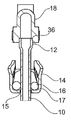
- FIG. 8 illustrates a cross-sectional view of the elements in the steps illustrated in FIG. 7.
- FIG. 9 illustrates the elements of FIG. 2 in a further step of the assembly method.
- FIG. 10 illustrates a cross-sectional view of the elements in the steps illustrated in FIG. 9.
- FIG. 11 is an enlarged view of a portion of the example of FIG. 10.
- FIG. 12 illustrates aspects of an easily assembled connection of a tube and a tank component as shown in FIG. 10.
- FIGS. 1 to 12 are described in more detail as examples or embodiments of the ideas described in the above summary. It should be noted that like reference numerals are used to like elements throughout the description of the embodiments and methods illustrated in FIGS.
- Tank component 18 has a tank opening 24 that allows fluid to cool a battery or other device into tube 10.
- FIG. 2 illustrates an exploded view of the assembly 26 of FIG. 1.
- the tube 10 has a tube end portion 12 to be connected to the tank component 18.
- This tube end portion 12 is located at the open end of the tube 10 and extends further downstream to a portion of the tube 10, ie away from the open end.
- the tube 10 has a flat configuration, in this example comprises a plurality of individual partial tubes, which are 18 individual partial tubes, each of which has individual openings 22 in the tube end portion 12, and the partial tubes are tubes It is integrally formed to constitute 10.
- the partial tubes, in this embodiment, are dimensioned to have a substantially square cross section.
- the partial tubes can have different shapes and dimensions, and the present disclosure is also applicable to a single tube, ie a single tube in which the outer wall is the only wall of the tube without a plurality of partial tubes being formed in the tube or in the outer wall. .
- the header 14 has a portion of the tube 10, that is, an unexpanded portion of the tube 10, fitted through the opening 15 of the header 14, surrounding the tube 10 and radially outward of the header 14.
- Tube 10 surrounded by tube 10 and header 14 and surrounded by gasket 16 allowing opening of gasket 16 around opening 15 intended to be surrounded by wall 17. It is dimensioned to compress between the radially outer walls 17 of and within the opening 15 of the header 14, which will be described in more detail below and illustrated in some of the figures below.
- the tank component 18 further illustrates a tank component 18 crimped to the header crimp portion 20.
- the tank component 18 has a tank crimp portion 21 that is configured to cooperate with the header crimp portion 20 to establish a form fit, ie having a size and a shape.
- the embodiment illustrated in the figures herein illustrates a wavy crimp connection between the header 14 and the tank component 18.
- FIG. 3 illustrates an assembly step of the assembly 26 illustrated in FIG. 1.
- the header 14 is disposed on the tube 10 to surround the tube 10 and is moved from the open end of the tube 10 to be connected to the tank component 18 so that this end of the tube 10 is moved. Make it accessible for further processing.
- the gasket 16 is disposed on the tube 10 to surround the tube 10 and is received by the header 14.
- the gasket 16 is disposed radially with respect to the tube axis between the tube 10 and the header 14, in particular the outer wall 17 of the header 14.
- 3 illustrates a partially assembled configuration of header 14, gasket 16, and tube 10, header 14, and gasket 16.
- FIG. 3 also illustrates the tube openings 22 of the partial tubes of the tube 10, where the gasket 16 and the header 14 are disposed on the tube 10, the tube to be connected to the tank component 18. It can be seen in FIG. 3 that the end of is not yet expanded but has approximately the same diameter as the rest of the tube 10. This diameter of the end of the tube is sized to allow the header 14, in particular the opening 15 and the gasket 16, to accept and surround the tube 10 in a fitting manner from the free end of the tube.
- the tool 28 includes a plurality of protrusions 30 to be inserted into the tube openings 22 at the free end of the tube 10.
- the tube 10 comprises 18 partial tubes.
- the tool 28 includes 18 protrusions 30, each of which is sized and arranged to push into one of the openings 22 of the tube 10, such that the openings 22 Each receive one protrusion 30 and expand radially to form an extended tube end portion 12 after the gasket 16 and header 14 slide over the free end of the tube 10. .
- FIG. 4 also illustrates the expanded tube end portion 12, ie the portion of the tube 10 that is connected to the tank component 18.
- FIG. 5 is a further illustration of the tool 28 and protrusions 30 thereof.
- the protrusions have a diameter where the free ends of the protrusions 13 to be inserted into the openings 22 of the tube 10 are smaller than the ends of the protrusions 30.
- 30 has a tapered configuration that is attached to a common base of tool 28.
- the tapering of the protrusions 30 is performed step by step.
- This may be the first tapered or cut, starting at a smaller diameter (less than the diameter of the opening 22) and ending with a diameter that may have, for example, the same or similar diameter as the corresponding opening 22 in the tube 10. It means that a cone exists.
- This truncated cone shape facilitates insertion of the protrusion 30 into the opening 22 of the tube 10.
- the projection may not be cylindrical, ie not tapered, to form an extended tube end portion 12 having the same diameter along the tube axis.
- the expansion of the tube 10, more precisely the expanded tube end 12, is in the range of 0.1 mm to 2.0 mm, especially for the configurations of the tube 10 used for cooling car batteries for electric vehicles, for example. Up to amount can be performed.
- FIG. 6 illustrates the tool 28 and the protrusions 30 when inserted into the free end of the tube 10, each of the openings 22 receiving one of the protrusions 30 of the tool 28. .
- an expanded tube end portion 12 is formed.
- the expanded tube end portion 12 is formed by plastically deforming the tube 10 (partial tubes of the tube).
- the tube 10 is a multilayer tube.
- the tube base 34 is made of a first material and can be used as a substrate for the coating 32 provided on the outer wall of the tube 10.
- the coating 32 can be, for example, an insulating coating, for example an electrically insulating coating that is particularly useful when the tube 10 is used for cooling batteries, which means that the tube 10 is a tank component ( 18) or already on the tube 10 before being connected to another device. Because the method according to the invention does not require soldering or welding steps that are naturally associated with high temperatures that can damage or even destroy coatings, the tube before the connection between the tube 10 and the tank component 18 is provided. It is possible to apply temperature-sensitive coatings 32 on the substrate 34 of 10. This reduces the efforts to provide a coated battery cooler or other tube connected to the tank component 18 to a potentially significant extent. That is, the method allows to provide assemblies with coated tubes at a relatively low cost.
- the tube 10 is provided with a gasket 16 and a header 14, and the expanded tube end portion 12 is formed by the tool 28 illustrated for example in FIGS. 5 and 6 and described above.
- the tube 10 After retracting the tool 28, the tube 10 maintains the expanded configuration at its end 12. That is, the expanded tube end portion 12 is formed by plastically deforming the tube 10 (partial tubes of the tube) and does not return to its original size after retracting the tool 28.
- the tank component 18 After the tool 28 is retracted from the end portion 12 of the tube 10, the tank component 18 is disposed on at least a partially expanded tube end end 12. The tank component 18 at least partially receives the expanded tube end portion 12 so that the interior of the tank component 18 has a tank opening 24 with openings of the tube 10 (partial tubes of the tube). 22) allow fluid communication with it.
- FIG. 8 illustrates a cross-sectional view of the configuration of FIG. 7.
- the expanded tube end portion 12 is partially received in the tank component 18 and in contact with the internal step 36 (described in more detail below) of the tank component 18. .
- the header 14 and the gasket 16 can be moved towards the tank component 18 to contact and crimp the tank component 18. have.
- FIG. 9 illustrates the configuration of the tube 10, the header 14 including the gasket 16 and the tank component 18 in an assembled state as in FIG. 1.
- the header crimp portion 20 and the tank crimp portion 21 form a wavy crimp connection and thus form conformation.
- a tap crimp configuration is also possible for the present disclosure.
- FIG. 10 illustrates a cross-sectional view of the assembled configuration of the header 14 and tank component 18.
- the tank crimp portion 21 and the header crimp portion 20 are arranged adjacent to each other, so that it is possible to crimp the header crimp portion 20 into the tank crimp portion 21.
- the header 14 is firmly connected to the tank component 18.
- an external step 38 is provided in FIG. 10 that provides form fit for the header crimp portion 20 configured as a wavy crimp. That is, the header crimp portion 20 is not only crimped to the tank crimp portion 21, but also shaped by the outer step 38 and the header crimp portion 20.
- the internal step 36 mentioned above in connection with the contact of the end of the tube 10 contained in the tank component 18 is illustrated.
- the gasket 16 is compressed between the outer wall 17 of the header 14 on the one hand and the expanded tube end portion 12 on the other.
- the gasket 16 is also squeezed between the axial end wall of the header 14 on the one hand and the tank component 18 on the other hand. In this way, a secure and secure connection between the tube 10 and the tank component 18 is provided.
- FIG. 11 illustrates a further enlarged view of the assembly in an assembled configuration.
- the expanded tube end portion 12 illustrates and compresses the gasket 16 against the radially outer wall 17 of the header 14.
- the gasket 16 is illustrated to overlap the expanded tube end portion 12.
- the gasket 16 is modified to fit between the expanded tube end portion 12 and the radially outer wall 17 as well as between the radially outer wall of the header 14 and the tank component 18.
- the tube 10 is coated before deforming the tube 10 to form an extended tube end portion 12 and connecting the tube 10 by the header 14 and the gasket 16 to the tank component 18. It can be seen in FIG. 11 that the tube base 34 on which the 32 is formed is included.
- FIG. 12 illustrates the configuration of FIGS. 9 to 11 in additional cross sectional view.
- DT represents the outer diameter of the tube 10 at the expanded tube end portion 12.
- DH refers to the diameter of the opening 15 of the header 14 to allow the tube 10 to be led into the interior of the tank component 18.
- the outer diameter DT of the tube 10 is larger than the diameter DH of the opening 15 such that there is a conformation that prevents the tube 10 from being retracted from the header 14.
- the inner step 36 allows the tube 10 to be pushed further into the tank component 18 and the relative positions of the tank component 18 on the one hand and the header 14 on the other hand on the one hand of the header ( Between the radial end wall of 14 and the tank component 18 on the other hand to ensure it is secured by the elastic forces of the outer step 38, the header crimp portion 20, the tank crimp portion 21 and the gasket 16. .
- the drawings of the present application illustrate a particularly preferred embodiment of the tube and tank component assembly and a method of mechanically assembling the tube and tank component, which allows to reliably connect the tube and tank component without soldering or welding steps.
- the present disclosure allows a temperature sensitive material, in particular a coating, to be applied to the tube 10 or other element of the assembly before completing an assembly method that improves reliability and reduces cost while providing an inexpensive and reliable manufacturing process.
- the present invention provides a battery cooler that cools a battery in batteries or similar environments of an electric vehicle.
Landscapes
- Engineering & Computer Science (AREA)
- Electrochemistry (AREA)
- Manufacturing & Machinery (AREA)
- Chemical & Material Sciences (AREA)
- Chemical Kinetics & Catalysis (AREA)
- General Chemical & Material Sciences (AREA)
- Physics & Mathematics (AREA)
- Thermal Sciences (AREA)
- Mechanical Engineering (AREA)
- General Engineering & Computer Science (AREA)
- Geometry (AREA)
- Battery Mounting, Suspending (AREA)
- Cooling, Air Intake And Gas Exhaust, And Fuel Tank Arrangements In Propulsion Units (AREA)
- Gasket Seals (AREA)
Abstract
본 출원은 특히 배터리 냉각기인 열 교환기(26)에 관한 것이고, 튜브(10) ― 튜브(10)는 튜브(10)의 개방 단부에 위치되는 튜브 단부 부분(12)을 갖고, 튜브 단부 부분(12)으로부터 더 멀리 튜브(10)의 확장되지 않은 부분에 대해 적어도 부분적으로 확장됨 ―, 개구(15) 및 방사상 외측 벽(17)을 갖는 헤더(14) ― 튜브(10)의 확장되지 않은 부분은 개구(15)를 통해 끼워짐 ―, 튜브(10)와 헤더(14)의 방사상 외측 벽(17) 사이에서 압축되도록 헤더(14)에 의해 수용되는 개스킷(16), 및 헤더(14)를 통해 튜브 단부 부분(12)에 연결되는 탱크 컴포넌트(18)를 포함한다. 본 출원에 따르면, 개스킷은 O-링이다. 본 출원은 추가로, 이러한 열 교환기를 조립하는 방법에 관한 것이다.
Description
현재 자동차 산업에서 전자 이동성을 향해 발생하는 일반적인 경향은 전기차와 같은 차량의 전기 시스템에서 배터리의 높은 용량, 고전력 출력 및 고전류를 향한 일반적인 경향을 도출한다. 제한된 차원들의 시스템 내에서 전력에서의 증가가 제공되도록 요구되는 다른 기술 분야들에서도 유사한 경향들이 관찰될 수 있다. 이러한 경향은 특히 배터리들 및 이들의 주변부로부터 발생하는 열 에너지에서의 증가를 초래한다. 따라서, 전기 자동차의 배터리들 또는 유사한 환경에서 배터리를 냉각시키는 것이 요구된다.
전기 자동차 또는 유사한 디바이스의 배터리 또는 배터리들을 냉각시키기 위해, 배터리 냉각기들이 당업계에 일반적으로 공지되어 있다.
본 개시가 적용될 수 있는 바람직한 배터리 냉각기의 예는 2018년 5월 29일에 출원된 대한민국 대전시 대덕구 306-230 신일서로 95 번지의 HANON SYSTEMS의 독일 특허 출원 DE 10 2018 208 473.4호에 개시되어 있다.
열 교환기(본원에서 "배터리 냉각기"로 지칭됨)의 사용, 냉각 본체(본 명세서에서 "튜브"로 지칭됨)의 형상, 크기, 재료, 코팅 및 제조, 매니폴드(본 명세서에서 "탱크 컴포넌트"로 지칭됨)의 형상, 크기, 재료, 코팅 및 제조, 매니폴드 베이스(본 명세서에서 "헤더"로 지칭됨)의 형상, 크기, 재료, 코팅 및 제조, 개스킷(본 명세서에서 "개스킷"로 지칭됨)의 형상, 크기, 재료, 코팅 및 제조와 관련된 DE 10 2018 208 473.4호의 설명은 참조로 본원에 각각 통합되어 있다.
본 개시는 배터리 셀들 사이에 삽입된 넓은 압출 튜브를 사용하는 DE 10 2018 208 473.4호에 설명된 배터리 냉각기와 같은 배터리 냉각기에 관한 것이며, 튜브는 탱크 컴포넌트로 진입하고, 그 다음, 탱크 컴포넌트는 튜브에 냉각 유체를 제공하기 위해 호스에 연결된다. 이러한 배터리 냉각기들의 현재의 설계들은 한편으로는 탱크 컴포넌트들과 다른 한편으로는 튜브 사이에 형성될 다소 복잡하고 부담스러운 연결을 요구한다. 본 개시의 제1 양상에 따르면, 목적은 탱크 컴포넌트를 튜브에 연결하는 것을 용이하게 하는 것이다. 본 개시의 제2 양상에 따르면, 목적은 이전의 설계들과 비교하여 더 저렴한 솔루션을 제공하는 것이다. 본 개시의 제3 양상에 따르면, 튜브와 탱크 컴포넌트 사이의 연결은, 조립체 전에, 특히 튜브와 탱크 컴포넌트 사이의 연결을 실시하기 전에 튜브에 인가된 코팅에 의해 튜브가 절연, 특히 전기 절연되도록 허용할 것이다. 본 개시의 제4 양상은 DE 10 2018 208 473.4호에 설명된 설계 및 조립 방법에 관한 대안적인 설계 및 조립 방법을 제공하는 것이다.
본 발명은 독립항들에서 정의되며, 바람직한 추가적인 특징들은 종속항들에 종속된다.
본 개시에 따르면, 튜브 및 탱크 컴포넌트는 조립 공정 동안 납땜 또는 용접을 사용하지 않고 기계적으로 조립된다. 이러한 공정은 먼저, 배터리 냉각기의 제조 동안 수행되기가 더 쉽다. 둘째로, 실제 조립 단계들에서 납땜 또는 용접을 요구하지 않는 기계적 조립은, 튜브가 (전기적으로 또는 다른 방법으로) 절연 코팅에 의해 또는 온도에 민감할 수 있는 임의의 다른 코팅에 의해 코팅되도록 허용한다. 즉, 본 개시에 따른 기계적 조립은 튜브에 임의의 코팅이 제공되거나 임의의 재료로 제조되도록 허용하며, 이는 납땜 또는 용접 동안 경험되는 것들과 같은 고온에 의해 잠재적으로 파괴 또는 손상된다.
본 개시에 따르면, 튜브 및 탱크 컴포넌트를 조립하는 단계는 튜브를 제공하는 단계, 튜브 상에 헤더를 배치하는 단계 및 튜브 상에 개스킷을 배치하는 단계를 포함한다.
개스킷 및 헤더는, 개스킷 및 헤더에 의해 탱크 컴포넌트에 연결될 단부인 튜브의 (자유) 단부가 조립체 공정의 다음 단계를 위해 액세스 가능한 방식으로 튜브 상에 배치된다. 개스킷 및 헤더는 탱크 컴포넌트와 연결될 단부를 통해 튜브 상에 배치될 수 있지만, 개스킷 및 헤더를 튜브의 대향 단부(존재하는 경우)를 통해 튜브 상에 배치하는 것이 물론 또한 가능하다.
본 개시에 따르면, 튜브가 탱크 컴포넌트에 연결되는 튜브의 단부는 개스킷과 한편으로는 헤더 사이에, 그리고 다른 한편으로는 (추후에) 탱크 컴포넌트 사이에 배치된다.
추가적 단계에서, 탱크 컴포넌트에 연결될 튜브 단부가 확장된다. 이것은 펀칭 나이프 또는 유사한 물체를 사용하여 각각의 튜브 단부를 확장시킴으로써 달성될 수 있다. 튜브 단부는 튜브의 전체 둘레에 걸쳐 확장될 수 있지만, 튜브 단부가 오직 부분적으로만 확장되는 것이 또한 가능하다. 튜브 단부를 전체 둘레에 걸쳐 확장하는 것은 튜브와 탱크 컴포넌트의 보다 안정적인 연결을 허용한다.
튜브 단부의 확장량은 특히 전기 자동차들을 위한 배터리 냉각기들에서 특히 0.1 mm 내지 2.0 mm일 수 있는데, 상기 언급된 튜브 확장량은, 한편으로는 튜브와 탱크 컴포넌트 사이의 연결에서 충분한 강도를 제공하기 때문에 바람직하다. 한편, 확장은 너무 크지 않아서 튜브 재료는 확장에 의해 손상되지 않고, 튜브와 탱크 컴포넌트 사이의 연결은 기밀하게 유지된다.
개스킷은 O-링 또는 변형된 O-링과 같은 일반적인 토러스 형태를 가질 수 있다. 이는, 개스킷이 링, 타원, 레이스트랙일 수 있거나, 평면도에서 그리고 개스킷의 일부의 단면도에서 변형될 수 있고, 이는 원형, 타원형일 수 있거나 변형될 수 있음을 의미한다. 형상의 변형들이 가능하다. 평면도에서, 개스킷은 원형, 타원형 또는 레이스트랙 형상을 가질 수 있거나, 또는 심지어 다각형, 특히 직사각형의 외형을 어느 정도 따를 수 있다. 본 개시와 관련하여, 개스킷이 튜브 및 헤더와 맞물릴 수 있는 방법을 고려하면, 앞서 언급된 평면도는 튜브의 메인 확장부를 따라, 즉 튜브 중심 축에 평행하고 탱크 컴포넌트에 연결될 단부 상으로의 뷰일 것이다.
개스킷은 확장되지 않은 튜브가 개스킷(원형, 타원형 또는 레이스트랙 형상)에 피팅(fit)되도록 허용하는 크기를 가질 수 있다. 튜브는 개스킷과 견고하게 맞물릴 수 있거나, 개스킷과 견고하게 맞물리도록 확장되어야 하는 형상일 수 있다. 개스킷이 튜브 단부로 이동되어 튜브 단부가 상술한 바와 같이 충분히 확장되면 튜브는 개스킷을 외측으로 압축한다.
튜브 단부가 확장된 경우, 튜브 단부를 확장시키기 위한 툴은 제거될 수 있고 튜브에 연결될 탱크 컴포넌트는 튜브의 확장된 단부 상에 배치될 수 있다. 사전에, 이후에 또는 동시에, 개스킷 및 헤더는 탱크 컴포넌트와 접촉하도록 튜브 단부를 향해 이동될 수 있다. 이러한 방식으로, 튜브와 탱크 컴포넌트 사이의 연결을 형성하기 위해 궁극적으로 협력하는 헤더 및 탱크 컴포넌트는 서로를 향해 이동하고 마지막으로 서로 접촉하며, 개스킷은 헤더와 탱크 컴포넌트 사이에 뿐만 아니라 헤더와 튜브 사이에 배치된다.
헤더 및 탱크 컴포넌트가 서로 접촉하는 경우, 튜브의 확장된 단부 부분은 헤더 또는 탱크 컴포넌트, 또는 둘 모두 및 잠재적으로 개스킷과 같은 추가적인 엘리먼트들에 의해 둘러싸인다. 이러한 구성에서, 개스킷은 튜브 축에 대해 방사상 방향으로, 한편으로는 확장된 튜브 단부와 다른 한편으로는 헤더 사이에서 압축된다. 또한, 탱크 컴포넌트는 헤더와 접촉하고 헤더와 탱크 컴포넌트는 함께 크림핑된다(crimped). 탱크 컴포넌트와 헤더를 함께 크링핑하는 가능한 방법들은 물결 모양 크림핑 또는 탭 크림핑이 있다.
헤더 및/또는 탱크 컴포넌트와 튜브 사이에서 탱크 컴포넌트 및/또는 헤더 및 개스킷에 의해 둘러싸인 확장된 튜브로 탱크 컴포넌트와 헤더를 함께 크림핑함으로써, 튜브와 탱크 컴포넌트 사이의 견고한 연결이 제공된다.
본 개시의 바람직한 개시에 따르면, 확장된 튜브 단부 상에 적어도 부분적으로 배치되는 탱크 컴포넌트는 튜브가 탱크 컴포넌트와 접하도록 허용하는 형상을 갖도록 구성된다. 예를 들어, 탱크 컴포넌트는 확장된 튜브 단부를 수용하기 위한 리세스를 포함할 수 있으며, 리세스는 내부 스텝, 플랜지, 또는 튜브의 단부에 접하기 위한 유사한 엘리먼트 또는 형상을 가질 수 있다. 따라서, 이는 튜브와 탱크 컴포넌트 사이의 연결 이후 튜브가 탱크 컴포넌트 내로 밀릴 수 없는 것이 보장된다. 또한, 이것은 튜브 단부가 탱크 컴포넌트 내로 정확하게 삽입되는 명확하게 정의된 단부 위치를 제공하는 것을 허용한다. 이러한 위치에서, 탱크 컴포넌트와 헤더의 크림핑이 수행될 수 있고, 제조 에러들, 부정확도들 및 잠재적 결과로서 디바이스의 고장의 위험이 신뢰가능하게 방지될 수 있다.
추가로, 헤더는 확장되지 않은 튜브 상에서 견고하게 피팅되고 튜브 축을 따라 이동가능하도록 하는 형상 및 크기일 수 있다. 헤더의 형상 및 크기는 확장된 튜브 단부가 헤더를 통해 이동하는 것을 회피하도록 선택될 수 있다. 즉, 튜브를 수용하기 위한 헤더의 개구는 튜브의 확장된 단부가 개구를 통해 이동하기에는 너무 견고하지만 확장되지 않은 튜브가 개구를 통해 이동하도록 허용하는 크기일 수 있다.
이는 튜브가 탱크 컴포넌트로부터 분리되는 것을 신뢰 가능하게 방지한다. 헤더 및 튜브의 이러한 설계에 대한 추가로 또는 대안으로, 개스킷은 또한 그에 따라 탱크 컴포넌트와 튜브 사이의 연결을 확고하게 유지하기에 충분한 힘을 제공하도록 설계될 수 있다. 이와 관련하여, 개스킷은 헤더 및 탱크 컴포넌트가 함께 크림핑되는 경우 튜브 상에 방사상 압축력을 가하도록 설계될 수 있으며, 이러한 방사상 압축력은, 확장된 튜브 단부가 실제 환경 하에서 한편으로는 튜브와 다른 한편으로는 탱크 컴포넌트 및/또는 헤더 사이의 연결로부터 당겨질 수 없도록 충분히 높게 선택될 수 있다.
전술한 방법으로 인해, 한편으로는 배터리 냉각기 또는 임의의 유사한 디바이스의 튜브 및 다른 한편으로는 탱크 컴포넌트 또는 다른 단자 엘리먼트를 연결하는 비교적 저렴하고, 용이하고 또한 매우 신뢰가능한 방법을 제공하는 것이 가능하다. 추가로, 이 방법은 상당한 열 영향 없는 순수한 기계적 조립 방법이기 때문에, 조립 전에 튜브 상에 코팅을 제공하는 것이 가능하며, 이는 코팅이 상당히 더 효율적인 방식으로 튜브 상에 제공되도록 허용한다.
다음은 다음 도면들에 예시되는 상기 아이디어의 예의 설명이다.
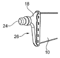
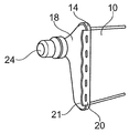
도 1은 튜브 및 탱크 컴포넌트의 완성된 조립체를 예시한다.
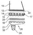
도 2는 도 1의 조립체를 위해 조립될 엘리먼트들의 분해도를 예시한다.
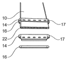
도 3은 조립 방법의 단계에서 도 2의 엘리먼트들 중 일부를 예시한다.
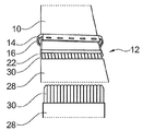
도 4는 조립 방법의 추가적 단계를 위한 엘리먼트들을 예시한다.
도 5는 탱크 컴포넌트에 연결되도록 튜브 단부를 확장하기 위한 툴을 예시한다.
도 6은 탱크 컴포넌트에 연결될 튜브의 단부를 확장하는 도 5에 또한 도시된 툴을 예시한다.
도 7은 조립 방법의 추가적 단계에서 도 2의 엘리먼트들을 예시한다.
도 8은 도 7에 예시된 단계에서 엘리먼트들의 단면도를 예시한다.
도 9는 조립 방법의 추가적 단계에서 도 2의 엘리먼트들을 예시한다.
도 10은 도 9에 예시된 단계에서 엘리먼트들의 단면도를 예시한다.
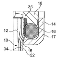
도 11은 도 10의 예시의 일부에 대한 확대도이다.
도 12는 도 10에 도시된 바와 같이 튜브와 탱크 컴포넌트의 용이하게 조립된 연결의 양상들을 예시한다.
이하에서, 도 1 내지 도 12는 상기 개요에서 설명된 아이디어의 예 또는 실시예로서 더 상세하게 설명된다. 도 1 내지 도 12에 예시된 실시예 및 방법의 설명 전반에 걸쳐 동일한 엘리먼트들에 대해 동일한 참조 부호들이 사용되는 것을 주목해야 한다.
도 1은 튜브(10) 및 탱크 컴포넌트(18)의 조립체(26)를 예시한다. 탱크 컴포넌트(18)는 배터리 또는 다른 디바이스를 냉각시키기 위한 유체가 튜브(10) 내로 공급될 수 있게 하는 탱크 개구(24)를 갖는다.
도 2는 도 1의 조립체(26)의 분해도를 예시한다. 도 2에서 볼 수 있는 바와 같이, 튜브(10)는 탱크 컴포넌트(18)에 연결될 튜브 단부 부분(12)을 갖는다. 이러한 튜브 단부 부분(12)은 튜브(10)의 개방 단부에 위치되며, 튜브(10)의 일부에 대해 더 먼 하류로, 즉 개방 단부로부터 멀리 확장된다. 튜브(10)는 평탄한 구성을 갖고, 이러한 예에서는 18개의 개별적인 부분적 튜브들인 복수의 개별적인 부분적 튜브들을 포함하고, 이들 각각은 튜브 단부 부분(12)에서 개별적인 개구(22)를 갖고, 부분적 튜브들은 튜브(10)를 구성하도록 일체형으로 형성된다. 부분적 튜브들은, 본 실시예에서, 실질적으로 정사각형 단면을 갖도록 치수화된다. 튜브(10)의 공통 외측 벽 내에 얼마나 많은 부분적 튜브들이 있는지는 튜브(10)의 외부로부터 항상 결정될 수는 없지만, 본 개시는 많은 상이한 종류들의 튜브들(10)에 대해 사용될 수 있다. 특히, 본 실시예에서와 같이 각각 개별적인 튜브인 복수의 병치된 부분적 튜브들을 갖는 평탄한 구성이 선호되는 구성인데, 이는, 이러한 구성이, 대량의 냉각 유체가 냉각될 배터리를 따라 전도되도록 허용하여, 냉각될 엘리먼트, 예를 들어, 배터리와 냉각 유체 사이에서 매우 효율적인 열 전달을 허용하기 때문이다. 그러나, 더 많거나 더 적은 부분적 튜브들이 튜브(10)에서 사용되는 것이 물론 가능하다. 부분적 튜브들이 다른 형상들 및 치수들을 갖는 것이 또한 가능하며, 본 개시는 또한 단일 튜브, 즉 튜브 내에 또는 외측 벽 내에 복수의 부분적 튜브들이 형성되지 않고 외측 벽이 튜브의 유일한 벽인 단일 튜브에 적용가능하다.
도 2는 헤더(14)와 일체형으로 형성되는 헤더 크림프 부분(20)을 갖는 헤더(14)를 추가로 예시한다. 헤더(14)는 튜브(10)의 일부, 즉 튜브(10)의 확장되지 않은 부분이 헤더(14)의 개구(15)를 통해 피팅되고, 튜브(10)를 둘러싸고 헤더(14)의 방사상 외측 벽(17)에 의해 둘러싸이도록 의도된 개구(15) 주위에서 개스킷(16)을 수용하도록 허용하여, 튜브(10)와 헤더(14)에 의해 둘러싸이고 개스킷(16)에 의해 둘러싸인 튜브(10)의 방사상 외측 벽(17) 사이에서 그리고 헤더(14)의 개구(15) 내에서 압축되도록 치수화되며, 이는 아래에서 더 상세히 설명될 것이고 하기 도면들 중 일부에서 예시되어 있다.
도 2는 헤더 크림프 부분(20)에 크림핑되는 탱크 컴포넌트(18)를 추가로 예시한다. 이러한 목적을 위해, 탱크 컴포넌트(18)는 형태 맞춤(fit)을 확립하기 위해 헤더 크림프 부분(20)과 협력하도록 구성되는, 즉, 크기 및 형상을 갖는 탱크 크림프 부분(21)을 갖는다. 본원의 도면들에 예시된 실시예는 헤더(14)와 탱크 컴포넌트(18) 사이의 물결 모양의 크림프 연결을 예시한다.
도 3은 도 1에 예시된 조립체(26)의 조립 단계를 예시한다. 이러한 단계에서, 헤더(14)는 튜브(10)를 둘러싸도록 튜브(10) 상에 배치되고 탱크 컴포넌트(18)에 연결될 튜브(10)의 개방 단부로부터 이동되어, 튜브(10)의 이러한 단부가 추가적인 처리를 위해 액세스 가능하게 한다. 또한, 개스킷(16)은 튜브(10)를 둘러싸도록 튜브(10) 상에 배치되고, 헤더(14)에 의해 수용된다. 따라서, 개스킷(16)은 튜브(10)와 헤더(14), 특히 헤더(14)의 외측 벽(17) 사이에서 튜브 축에 대해 방사상 방향으로 배치된다. 도 3은 헤더(14), 개스킷(16), 및 튜브(10), 헤더(14) 및 개스킷(16)의 부분적으로 조립된 구성을 예시한다. 도 3은 또한 튜브(10)의 부분적 튜브들의 튜브 개구들(22)을 예시하며, 개스킷(16) 및 헤더(14)가 튜브(10) 상에 배치되는 경우, 탱크 컴포넌트(18)에 연결될 튜브의 단부는 아직 확장되지 않지만 튜브(10)의 나머지와 대략 동일한 직경을 가짐을 도 3에서 볼 수 있다. 튜브의 단부의 이러한 직경은, 헤더(14), 특히 개구(15) 및 개스킷(16)이 튜브의 자유 단부로부터 튜브(10)를 피팅 방식으로 수용하고 둘러싸도록 허용하는 크기를 갖는다.
도 4는 탱크 컴포넌트(18)에 연결되도록 튜브(10)의 단부를 확장시켜 확장된 튜브 단부 부분(12)을 형성하기 위해 사용될 수 있는 펀칭 나이프와 같은 툴(28)을 예시한다. 도 4에서 알 수 있는 바와 같이, 툴(28)은 튜브(10)의 자유 단부에서 튜브 개구들(22) 내로 삽입될 복수의 돌출부들(30)을 포함한다. 본원의 도면들에 예시된 실시예에서, 튜브(10)는 18개의 부분적 튜브들을 포함한다. 따라서, 툴(28)은 18개의 돌출부들(30)을 포함하며, 돌출부(30) 각각은 튜브(10)의 개구들(22) 중 하나에 푸시되도록 하는 크기를 갖고 배열되어, 개구들(22) 각각은 하나의 돌출부(30)를 수용하고, 개스킷(16) 및 헤더(14)가 튜브(10)의 자유 단부 위로 미끄러진 이후, 확장된 튜브 단부 부분(12)을 형성하도록 방사상으로 확장된다.
따라서, 도 4는 또한 확장된 튜브 단부 부분(12), 즉 탱크 컴포넌트(18)에 연결되는 튜브(10)의 부분을 예시한다.
도 5는 툴(28) 및 이의 돌출부들(30)의 추가적인 예시이다. 도 5에서 볼 수 있는 바와 같이, 돌출부들은 튜브(10)의 개구(22)들 내로 삽입될 돌출부들(13)의 자유 단부들이 돌출부들(30)의 단부들보다 작은 직경을 갖고, 여기서 돌출부들(30)은 툴(28)의 공통 베이스에 부착되는 테이퍼링된(tapered) 구성을 갖는다.
도 5에 예시된 구성에서, 돌출부들(30)의 테이퍼링은 단계적으로 수행된다. 이것은, 작은 직경(개구(22)의 직경보다 작음)에서 시작하여, 예를 들어 튜브(10) 내의 대응하는 개구(22)와 동일하거나 유사한 직경을 가질 수 있는 직경으로 끝나는 제1 테이퍼 또는 절단된 원뿔이 존재함을 의미한다. 이러한 절단된 원뿔 형상은 돌출부(30)를 튜브(10)의 개구(22) 내로 삽입하는 것을 용이하게 한다. 돌출부(30)의 자유 단부로부터 더 멀리 떨어져서, 돌출부(30)가 튜브(10) 내로 더 삽입될 때 튜브 개구(22) 및 튜브(10)의 단부를 확장시키기 위한 제2 테이퍼가 존재할 수 있다. 돌출부(30)의 자유 단부로부터 더 멀리 떨어져서, 돌출부는 튜브 축을 따라 동일한 직경을 갖는 확장된 튜브 단부 부분(12)를 형성하기 위해 원통형, 즉 테이퍼링되지 않을 수 있다.
튜브(10), 더욱 정확하게는 확장된 튜브 단부(12)의 확장은, 특히 예를 들어, 전기차에 대한 자동차 배터리들을 냉각시키기 위해 사용되는 튜브(10)의 구성들에 대해 0.1 mm 내지 2.0 mm의 양까지 수행될 수 있다.
도 6은 튜브(10)의 자유 단부 내로 삽입되는 경우 툴(28) 및 돌출부들(30)을 예시하며, 개구들(22) 각각은 툴(28)의 돌출부들(30) 중 하나를 수용한다. 이러한 방식으로, 확장된 튜브 단부 부분(12)이 형성된다. 확장된 튜브 단부 부분(12)은 튜브(10)(튜브의 부분적 튜브들)를 소성 변형시킴으로써 형성된다.
도 6에서 추가로 알 수 있는 바와 같이, 튜브(10)는 다층 튜브이다. 튜브 베이스(34)는 제1 재료로 제조되며, 튜브(10)의 외측 벽 상에 제공된 코팅(32)을 위한 기판으로서 사용될 수 있다. 코팅(32)은 예를 들어, 절연 코팅일 수 있는데, 예를 들어, 튜브(10)가 냉각 배터리들에 대해 사용되면 특히 유용한 전기 절연 코팅일 수 있고, 이는, 튜브(10)가 탱크 컴포넌트(18) 또는 다른 디바이스에 연결되기 전에 이미 튜브(10) 상에 제공된다. 본 발명에 따른 방법은 코팅들을 손상시키거나 심지어 파괴할 수 있는 고온들과 자연적으로 연관된 납땜 또는 용접 단계들을 요구하지 않기 때문에, 튜브(10)와 탱크 컴포넌트(18) 사이의 연결이 제공되기 전에 튜브(10)의 기판(34) 상에 온도-감응 코팅들(32)을 적용하는 것이 가능하다. 이는, 잠재적으로 상당한 범위까지 탱크 컴포넌트(18)에 연결된 코팅된 배터리 냉각기 또는 다른 튜브를 제공하기 위한 노력들을 감소시킨다. 즉, 본 방법은 비교적 저렴한 비용으로 코팅된 튜브들을 갖는 조립체들을 제공하도록 허용한다.
도 7은 본 개시에 따른 조립 방법의 추가적인 단계를 예시한다. 튜브(10)에는 개스킷(16) 및 헤더(14)가 제공되고, 확장된 튜브 단부 부분(12)은 예를 들어 도 5 및 도 6에 예시되고 앞서 설명된 툴(28)에 의해 형성된다.
툴(28)를 후퇴시킨 후에, 튜브(10)는 그 단부(12)에서 확장된 구성을 유지한다. 즉, 확장된 튜브 단부 부분(12)은 튜브(10)(튜브의 부분적 튜브들)를 소성 변형시킴으로써 형성되고, 툴(28)를 후퇴시킨 후 원래의 크기로 복귀하지 않는다. 툴(28)이 튜브(10)의 단부 부분(12)으로부터 후퇴된 후, 탱크 컴포넌트(18)는 적어도 부분적으로 확장된 튜브 단부 단부(12) 상에 배치된다. 탱크 컴포넌트(18)는 확장된 튜브 단부 부분(12)을 적어도 부분적으로 수용하여, 탱크 컴포넌트(18)의 내부는 탱크 개구(24)가 튜브(10)(튜브의 부분적 튜브들)의 개구들(22)과 유체 연통되도록 허용한다.
도 8은 도 7의 구성의 단면도를 예시한다. 도 8에서 알 수 있는 바와 같이, 확장된 튜브 단부 부분(12)은 탱크 컴포넌트(18)에 부분적으로 수용되고 탱크 컴포넌트(18)의 내부 스텝(36)(아래에서 더 상세히 설명됨)과 접촉한다. 탱크 컴포넌트(18)가 튜브(10)의 단부와 접촉하는 경우, 헤더(14) 및 개스킷(16)은 탱크 컴포넌트(18)를 향해 이동되어, 탱크 컴포넌트(18)와 접촉하고 그에 크림핑될 수 있다.
도 9는 도 1에서와 같이 조립된 상태의 튜브(10), 개스킷(16)을 포함하는 헤더(14) 및 탱크 컴포넌트(18)의 구성을 예시한다. 도 9에서 알 수 있는 바와 같이, 헤더 크림프 부분(20) 및 탱크 크림프 부분(21)은 물결 모양 크림프 연결을 형성하고 그에 따라 형태 맞춤을 형성한다. 물결 모양 크림프에 대한 대안으로서 또는 그에 추가하여, 또한 탭 크림프 구성이 본 개시에 대해 가능하다. 헤더(14)를 탱크 컴포넌트(18)에 크림핑함으로써, 본 기술 분야의 유체 기밀성에 대한 요건에 부합하는 적어도 유체 기밀인 연결이 달성된다.
도 10은 헤더(14) 및 탱크 컴포넌트(18)의 조립된 구성의 단면도를 예시한다. 도 10에서 알 수 있는 바와 같이, 탱크 크림프 부분(21) 및 헤더 크림프 부분(20)은 서로 인접하게 배치되어, 헤더 크림프 부분(20)을 탱크 크림프 부분(21)로 크림핑하는 것이 가능하다. 따라서, 헤더(14)는 탱크 컴포넌트(18)에 견고하게 연결된다. 헤더(14) 및 탱크 컴포넌트(18)가 조립된 구성인 경우, 물결 모양 크림프로서 구성된 헤더 크림프 부분(20)에 대한 형태 맞춤을 제공하는 외부 스텝(38)이 도 10에 예시되어 있다. 즉, 헤더 크림프 부분(20)은 탱크 크림프 부분(21)에 크림핑될 뿐만 아니라 외부 스텝(38) 및 헤더 크림프 부분(20)에 의해 형태 맞춤이 제공된다.
탱크 컴포넌트(18)의 내부에는, 탱크 컴포넌트(18)에 수용된 튜브(10)의 단부의 접촉과 관련하여 앞서 언급된 내부 스텝(36)이 예시되어 있다. 추가로, 개스킷(16)은 한편으로는 헤더(14)의 외측 벽(17)과 다른 한편으로는 확장된 튜브 단부 부분(12) 사이에서 압착되는 것을 도 10에서 알 수 있다. 개스킷(16)은 또한 한편으로는 헤더(14)의 축방향 단부 벽과 다른 한편으로는 탱크 컴포넌트(18) 사이에서 압착된다. 이러한 방식으로, 튜브(10)와 탱크 컴포넌트(18) 사이의 견고하고 안전한 연결이 제공된다.
도 11은 조립된 구성에서 조립체의 추가적인 확대도를 예시한다. 확장된 튜브 단부 부분(12)은 개스킷(16)을 헤더(14)의 방사상 외측 벽(17)에 대해 예시하고 압축한다. 개스킷(16)은 확장된 튜브 단부 부분(12)과 중첩하도록 예시되어 있다. 조립 시에, 개스킷(16)은 확장된 튜브 단부 부분(12)과 방사상 외측 벽(17) 사이 뿐만 아니라 헤더(14)의 방사상 외측 벽과 탱크 컴포넌트(18) 사이에 끼워지도록 변형된다. 튜브(10)는, 확장된 튜브 단부 부분(12)을 형성하도록 튜브(10)를 변형시키고 튜브(10)를 헤더(14) 및 개스킷(16)에 의해 탱크 컴포넌트(18)에 연결하기 전에 코팅(32)이 형성되는 튜브 베이스(34)를 포함하는 것을 도 11에서 알 수 있다.
도 12는 도 9 내지 도 11의 구성을 추가적인 단면도로 예시한다. 도 12에서, "DT"는 확장된 튜브 단부 부분(12)에서 튜브(10)의 외경을 나타낸다. "DH"는 튜브(10)가 탱크 컴포넌트(18)의 내부로 인도되도록 하는 헤더(14)의 개구(15)의 직경을 나타낸다.
튜브(10)의 외경 DT는 튜브(10)가 헤더(14)로부터 후퇴될 수 없게 하는 형태 맞춤이 존재하도록 개구(15)의 직경 DH보다 큰 것을 알 수 있다. 내부 스텝(36)은, 튜브(10)가 탱크 컴포넌트(18) 내로 추가로 밀릴 수 없고, 한편으로는 탱크 컴포넌트(18) 및 다른 한편으로는 헤더(14)의 상대적 위치들이 한편으로는 헤더(14)의 방사상 단부 벽과 다른 한편으로는 탱크 컴포넌트(18) 사이에서 외부 스텝(38), 헤더 크림프 부분(20), 탱크 크림프 부분(21) 및 개스킷(16)의 탄성력에 의해 고정되도록 보장한다.
본 출원의 도면들은 튜브 및 탱크 부품 조립체의 특히 바람직한 실시예 및 튜브 및 탱크 컴포넌트를 기계적으로 조립하는 방법을 예시하며, 이는 납땜 또는 용접 단계들 없이 튜브 및 탱크 컴포넌트를 신뢰가능하게 연결시키도록 허용한다. 본 개시는 저렴하고 신뢰가능한 제조 공정을 제공함과 동시에, 신뢰성을 개선하고 비용을 감소시키는 조립 방법을 완료하기 전에 튜브(10) 또는 조립체의 다른 엘리먼트에 온도 감응 재료, 특히 코팅이 적용되도록 허용한다.
본 발명은 전기 자동차의 배터리들 또는 유사한 환경에서 배터리를 냉각시키는 배터리 냉각기를 제공한다.
Claims (13)
- 특히 배터리 냉각기인 열 교환기(26)로서,튜브(10) ― 상기 튜브(10)는 상기 튜브(10)의 개방 단부에 위치되는 튜브 단부 부분(12)을 갖고, 상기 튜브 단부 부분(12)으로부터 더 멀리 상기 튜브(10)의 확장되지 않은 부분에 대해 적어도 부분적으로 확장됨 ―,개구(15) 및 방사상 외측 벽(17)을 갖는 헤더(14) ― 상기 튜브(10)의 확장되지 않은 부분은 상기 개구(15)를 통해 끼워짐 ―,상기 튜브(10)와 상기 헤더(14)의 방사상 외측 벽(17) 사이에서 압축되도록 상기 헤더(14)에 의해 수용되는 개스킷(16), 및상기 헤더(14)를 통해 상기 튜브 단부 부분(12)에 연결되는 탱크 컴포넌트(18)를 포함하고,상기 개스킷은 O-링인,열 교환기(26).
- 제1항에 있어서,상기 개스킷(16)은 타원형 형태, 레이스트랙 형태 또는 다각형 형태를 갖도록 평면도에서 변형되는,열 교환기(26).
- 제1항에 있어서,상기 개스킷(16)은, 상기 헤더(14) 및 상기 탱크 컴포넌트(18)가 함께 크림핑되는 경우, 상기 튜브 상에 방사상 압축력을 가하고,바람직하게는 상기 헤더(14)의 방사상 단부 벽과 상기 탱크 컴포넌트(18) 사이에 탄성력을 가하도록 구성되는,열 교환기(26).
- 제1항에 있어서,상기 튜브(10)는 상기 튜브 단부 부분(12)에 튜브 개구(22)를 각각 갖는 복수의 부분적 튜브들로 구성되고,상기 부분적 튜브들은 바람직하게는 병치되고,상기 부분적 튜브들은 바람직하게는 정사각형 단면을 갖는,열 교환기(26).
- 제1항에 있어서,상기 튜브(10)는 평탄한,열 교환기(26).
- 제1항에 있어서,상기 헤더(14)는 헤더 크림프 부분(20)을 포함하고, 상기 탱크 컴포넌트(18)는 탱크 크림프 부분(21)을 갖고,상기 탱크 크림프 컴포넌트(21)는 상기 헤더 크림프 부분(20)과 협력하여 형태 맞춤, 특히 상기 헤더(14)와 상기 탱크 컴포넌트(18) 사이의 물결 모양 크림프 연결을 확립하는,열 교환기(26).
- 제1항에 있어서,상기 개스킷(16)은 상기 탱크 컴포넌트(18)와 상기 헤더(14) 사이에서 압축되는,열 교환기(26).
- 제1항에 있어서,상기 탱크 컴포넌트(18)는, 상기 튜브(10)가 상기 탱크 컴포넌트(18)와 접촉하는 상기 확장된 튜브 단부 부분(12)을 수용하기 위한 리세스를 포함하는,열 교환기(26).
- 제1항에 있어서,상기 탱크 컴포넌트(18)는, 상기 확장된 튜브 단부 부분(12)과의 접촉을 위한 내부 스텝(36) 또는 플랜지를 포함하고,상기 확장된 튜브 단부 부분(12)과의 접촉을 위한 상기 내부 스텝(36) 또는 플랜지는 바람직하게는 상기 확장된 튜브 단부 부분(12)을 수용하기 위한 리세스 내에 제공되는,열 교환기(26).
- 제1항에 있어서,상기 헤더(14)의 개구(15)는, 상기 확장된 튜브 단부 부분(12)이 상기 개구(15)를 통해 이동하기에는 너무 견고하지만 상기 확장되지 않은 튜브 부분이 상기 개구(15)를 향해 이동하도록 허용하는 크기를 갖는,열 교환기(26).
- 열 교환기(26)를 조립하는 방법으로서,튜브(10)의 개방 단부에 위치되는 튜브 단부 부분(12)을 갖는 튜브(10)를 제공하는 단계;상기 튜브가 헤더(14)의 개구(15)를 통해 끼워지도록 개구(15) 및 방사상 외측 벽(17)을 갖는 상기 헤더(14)를 상기 튜브(10) 상에 배치하는 단계;상기 튜브(10)와 상기 방사상 외측 벽(17) 사이에서 상기 헤더(14)에 의해 수용되도록 상기 튜브(10) 상에 O-링인 개스킷(16)을 배치하는 단계;상기 튜브 단부 부분(12)을 적어도 부분적으로 확장시키는 단계;상기 헤더(14)와 접촉하도록 상기 확장된 튜브 단부 부분(12) 상에 탱크 컴포넌트(18)를 배치하는 단계 ― 상기 개스킷(16)은 상기 헤더(14)와 상기 탱크 컴포넌트(18) 사이에 배치됨 ―; 및상기 탱크 컴포넌트(18) 및/또는 헤더(14)에 의해 둘러싸인 상기 확장된 튜브 단부 부분(12)과 함께 상기 헤더(14) 및 상기 탱크 컴포넌트(18)를 크림핑하는 단계를 포함하는,방법.
- 제11항에 있어서,상기 열 교환기(26)는 제1항 내지 제10항 중 어느 한 항의 열 교환기인,방법.
- 제11항에 있어서,상기 튜브 단부 부분(12)은 상기 튜브 단부 부분(12)을 통해 상기 튜브(10)에 펀칭 나이프를 삽입함으로써 확장되는,방법.
Priority Applications (2)
| Application Number | Priority Date | Filing Date | Title |
|---|---|---|---|
| US17/054,406 US11967691B2 (en) | 2018-06-29 | 2019-06-28 | Battery cooler including O-ring compressed between pipe and radial outside wall of head part, and method of assembling the same |
| CN201980028651.2A CN112041629B (zh) | 2018-06-29 | 2019-06-28 | 电池冷却器 |
Applications Claiming Priority (4)
| Application Number | Priority Date | Filing Date | Title |
|---|---|---|---|
| DE102018115804.1 | 2018-06-29 | ||
| DE102018115804 | 2018-06-29 | ||
| DE102018219171.9 | 2018-11-09 | ||
| DE102018219171.9A DE102018219171A1 (de) | 2018-06-29 | 2018-11-09 | Batteriekühler |
Publications (1)
| Publication Number | Publication Date |
|---|---|
| WO2020005008A1 true WO2020005008A1 (ko) | 2020-01-02 |
Family
ID=68886439
Family Applications (1)
| Application Number | Title | Priority Date | Filing Date |
|---|---|---|---|
| PCT/KR2019/007882 Ceased WO2020005008A1 (ko) | 2018-06-29 | 2019-06-28 | 배터리 냉각기 |
Country Status (5)
| Country | Link |
|---|---|
| US (1) | US11967691B2 (ko) |
| KR (1) | KR102188116B1 (ko) |
| CN (1) | CN112041629B (ko) |
| DE (1) | DE102018219171A1 (ko) |
| WO (1) | WO2020005008A1 (ko) |
Families Citing this family (3)
| Publication number | Priority date | Publication date | Assignee | Title |
|---|---|---|---|---|
| DE102019129828A1 (de) * | 2019-11-05 | 2021-05-06 | Norma Germany Gmbh | Verbinder und Verbinderanordnung für Mehrkammerprofile und/oder -leitungen |
| DE102020202962A1 (de) | 2020-03-09 | 2021-09-09 | Hanon Systems | Sammler eines Wärmeübertragers für ein Fahrzeug und derartiger Wärmeübertrager |
| EP4332421B1 (en) * | 2022-08-29 | 2025-06-25 | Valeo Systemes Thermiques | A battery cooler |
Citations (5)
| Publication number | Priority date | Publication date | Assignee | Title |
|---|---|---|---|---|
| JP2005121350A (ja) * | 2003-05-29 | 2005-05-12 | Denso Corp | 熱交換器およびその製造方法 |
| KR20110032021A (ko) * | 2009-09-22 | 2011-03-30 | 한라공조주식회사 | 열교환기 |
| KR20110097166A (ko) * | 2010-02-24 | 2011-08-31 | 한라공조주식회사 | 라디에이터 |
| KR20110121021A (ko) * | 2010-04-30 | 2011-11-07 | 한라공조주식회사 | 라디에이터 |
| KR20170142733A (ko) * | 2016-06-20 | 2017-12-28 | 갑을오토텍(주) | 열교환기 |
Family Cites Families (16)
| Publication number | Priority date | Publication date | Assignee | Title |
|---|---|---|---|---|
| DE3841470A1 (de) * | 1988-12-09 | 1990-06-13 | Sueddeutsche Kuehler Behr | Wasserkastenklemmverbindung |
| DE4445590C2 (de) * | 1994-12-20 | 2001-02-01 | Behr Gmbh & Co | Verfahren zum Aufweiten der Rohrenden von Rohren eines Wärmetauschers, Werkzeug zur Durchführung des Verfahrens sowie nach dem Verfahren und mit dem Werkzeug hergestellter Wärmetauscher |
| FR2789758B1 (fr) * | 1998-11-30 | 2001-04-27 | Valeo Thermique Moteur Sa | Procede d'assemblage d'un echangeur de chaleur, en particulier de vehicule automobile, et echangeur ainsi obtenu |
| DE10114078A1 (de) * | 2001-03-22 | 2002-09-26 | Modine Mfg Co | Wärmetauscher und Herstellungsverfahren |
| JP2004063654A (ja) * | 2002-07-26 | 2004-02-26 | Hitachi Cable Ltd | 電子機器冷却装置 |
| FR2873800B1 (fr) * | 2004-07-30 | 2006-11-24 | Valeo Thermique Moteur Sas | Echangeur de chaleur a assemblage mecanique et joint d'etancheite pour cet echangeur de chaleur |
| FR2875592B1 (fr) * | 2004-09-17 | 2007-02-16 | Valeo Thermique Moteur Sas | Echangeur de chaleur a boite collectrice sertie et procede d'assemblage |
| DE102010032899A1 (de) * | 2010-07-30 | 2012-02-02 | Valeo Klimasysteme Gmbh | Kühlvorrichtung für eine Fahrzeugbatterie sowie Fahrzeugbatteriebaugruppe mit einer solchen Kühlvorrichtung |
| FR2967764B1 (fr) | 2010-11-19 | 2012-12-21 | Valeo Systemes Thermiques | Boite collectrice et echangeur de chaleur correspondant |
| KR101932205B1 (ko) * | 2012-08-27 | 2018-12-26 | 한온시스템 주식회사 | 열교환기 |
| CN202866976U (zh) * | 2012-08-30 | 2013-04-10 | 长城汽车股份有限公司 | 扩口式冷却管及汽车散热器 |
| JP6394202B2 (ja) | 2013-11-27 | 2018-09-26 | 株式会社デンソー | 熱交換器 |
| FR3020671B1 (fr) * | 2014-05-05 | 2016-06-10 | Valeo Systemes Thermiques | Collecteur pour un echangeur thermique de vehicule automobile |
| FR3054729B1 (fr) | 2016-07-27 | 2019-12-13 | Valeo Systemes Thermiques | Dispositif de refroidissement de batteries et procede de fabrication correspondant |
| DE202018102555U1 (de) * | 2018-05-08 | 2018-07-12 | Qingdao Auto Radiator Co., Ltd. | Hocheffektiver Rohr/Wellrippen-Kühler aus Aluminium mit geringer Ionenfreisetzung |
| DE102018208473B4 (de) | 2018-05-29 | 2022-09-15 | Hanon Systems | Wärmetauscher sowie Verfahren zum Herstellen eines Wärmetauschers |
-
2018
- 2018-11-09 DE DE102018219171.9A patent/DE102018219171A1/de active Pending
-
2019
- 2019-05-16 KR KR1020190057374A patent/KR102188116B1/ko active Active
- 2019-06-28 US US17/054,406 patent/US11967691B2/en active Active
- 2019-06-28 CN CN201980028651.2A patent/CN112041629B/zh active Active
- 2019-06-28 WO PCT/KR2019/007882 patent/WO2020005008A1/ko not_active Ceased
Patent Citations (5)
| Publication number | Priority date | Publication date | Assignee | Title |
|---|---|---|---|---|
| JP2005121350A (ja) * | 2003-05-29 | 2005-05-12 | Denso Corp | 熱交換器およびその製造方法 |
| KR20110032021A (ko) * | 2009-09-22 | 2011-03-30 | 한라공조주식회사 | 열교환기 |
| KR20110097166A (ko) * | 2010-02-24 | 2011-08-31 | 한라공조주식회사 | 라디에이터 |
| KR20110121021A (ko) * | 2010-04-30 | 2011-11-07 | 한라공조주식회사 | 라디에이터 |
| KR20170142733A (ko) * | 2016-06-20 | 2017-12-28 | 갑을오토텍(주) | 열교환기 |
Also Published As
| Publication number | Publication date |
|---|---|
| KR102188116B1 (ko) | 2020-12-08 |
| US20210249711A1 (en) | 2021-08-12 |
| US11967691B2 (en) | 2024-04-23 |
| CN112041629A (zh) | 2020-12-04 |
| KR20200002600A (ko) | 2020-01-08 |
| CN112041629B (zh) | 2022-05-10 |
| DE102018219171A1 (de) | 2020-01-02 |
Similar Documents
| Publication | Publication Date | Title |
|---|---|---|
| US10014600B1 (en) | Terminal crimping structure and connector with cable | |
| US20130084741A1 (en) | Electromagnetic Shielding Device | |
| US7763808B2 (en) | Hermetic electrical feedthrough assembly for a compressor and method for making the same | |
| WO2020005008A1 (ko) | 배터리 냉각기 | |
| US7695331B2 (en) | Electrical contact assembly including a sleeve member | |
| EP2996210B1 (en) | Hyperboloid electrical contact | |
| EP0597579A2 (en) | Coaxial cable-to-cable splice connector | |
| KR100530580B1 (ko) | 커넥터 조립체 및 케이블 접지 방법 | |
| KR20190045306A (ko) | 전기 플러그 커넥터용 전기 전도성 접촉 요소 | |
| US6100467A (en) | Water cooled kickless electrical cable | |
| WO2019231209A1 (ko) | 열 교환기 및 열 교환기 제조 방법 | |
| EP3828037A1 (en) | Arrangement for attaching an insulator sleeve to an electrical conductor | |
| JP2024160968A (ja) | 電気接続部材、電気接続アセンブリ、および充電台アセンブリ | |
| US20060270285A1 (en) | Connector assembly and method of making same | |
| US9293868B2 (en) | Attachment ring for attaching a shield of a cable to a shell | |
| EP0022627A1 (en) | Electrical connector for terminating coaxial electrical cable | |
| JPH0492378A (ja) | 同軸ケーブルの接続装置および接続方法 | |
| CN115051194B (zh) | 连接器及电子设备 | |
| US20240396276A1 (en) | Power conector system | |
| US20220181818A1 (en) | Cable connector and method for manufacturing cable connector | |
| JPH0247573Y2 (ko) | ||
| US20110097916A1 (en) | Device for preventing the establishment of an electric arc between two conductive elements | |
| JP2000030830A (ja) | ガス絶縁電気機器の導体接続部 |
Legal Events
| Date | Code | Title | Description |
|---|---|---|---|
| 121 | Ep: the epo has been informed by wipo that ep was designated in this application |
Ref document number: 19824734 Country of ref document: EP Kind code of ref document: A1 |
|
| 122 | Ep: pct application non-entry in european phase |
Ref document number: 19824734 Country of ref document: EP Kind code of ref document: A1 |