WO2020004609A1 - 音波処理装置、および超音波システム - Google Patents
音波処理装置、および超音波システム Download PDFInfo
- Publication number
- WO2020004609A1 WO2020004609A1 PCT/JP2019/025772 JP2019025772W WO2020004609A1 WO 2020004609 A1 WO2020004609 A1 WO 2020004609A1 JP 2019025772 W JP2019025772 W JP 2019025772W WO 2020004609 A1 WO2020004609 A1 WO 2020004609A1
- Authority
- WO
- WIPO (PCT)
- Prior art keywords
- unit
- correlation
- value
- data
- wave
- Prior art date
- Legal status (The legal status is an assumption and is not a legal conclusion. Google has not performed a legal analysis and makes no representation as to the accuracy of the status listed.)
- Ceased
Links
Images


























Classifications
-
- G—PHYSICS
- G01—MEASURING; TESTING
- G01S—RADIO DIRECTION-FINDING; RADIO NAVIGATION; DETERMINING DISTANCE OR VELOCITY BY USE OF RADIO WAVES; LOCATING OR PRESENCE-DETECTING BY USE OF THE REFLECTION OR RERADIATION OF RADIO WAVES; ANALOGOUS ARRANGEMENTS USING OTHER WAVES
- G01S15/00—Systems using the reflection or reradiation of acoustic waves, e.g. sonar systems
- G01S15/02—Systems using the reflection or reradiation of acoustic waves, e.g. sonar systems using reflection of acoustic waves
- G01S15/06—Systems determining the position data of a target
- G01S15/08—Systems for measuring distance only
- G01S15/32—Systems for measuring distance only using transmission of continuous waves, whether amplitude-, frequency-, or phase-modulated, or unmodulated
-
- G—PHYSICS
- G01—MEASURING; TESTING
- G01S—RADIO DIRECTION-FINDING; RADIO NAVIGATION; DETERMINING DISTANCE OR VELOCITY BY USE OF RADIO WAVES; LOCATING OR PRESENCE-DETECTING BY USE OF THE REFLECTION OR RERADIATION OF RADIO WAVES; ANALOGOUS ARRANGEMENTS USING OTHER WAVES
- G01S7/00—Details of systems according to groups G01S13/00, G01S15/00, G01S17/00
- G01S7/52—Details of systems according to groups G01S13/00, G01S15/00, G01S17/00 of systems according to group G01S15/00
- G01S7/537—Counter-measures or counter-counter-measures, e.g. jamming, anti-jamming
Definitions
- the present invention relates to a sonicator and an ultrasonic system.
- an ultrasonic system which measures a distance to an obstacle by measuring a time TOF (Time $ Of Flight) from generation of a sound wave to return of a reflected wave from the obstacle.
- TOF Time $ Of Flight
- an ultrasonic system is often mounted on a vehicle, and an on-vehicle clearance sonar is known as an example.
- waveform data (reference data) expected to be received is prepared, and a correlation convolution integration process is performed based on the reference data and the actually received signal to perform reflection.
- a method that emphasizes waves is also called a pulse compression method and can improve the S / N ratio.
- the pulse compression method is described in, for example, Patent Document 1.
- JP 2005-152450 A (paragraph 0011 and the like)
- the frequency of the ultrasonic wave to be transmitted and the waveform frequency of the reference data are fixed values that do not perform frequency modulation. Therefore, there is no characteristic in the ultrasonic wave, and it is difficult to distinguish between the ultrasonic wave of the same frequency transmitted from another ultrasonic system and the reflected wave transmitted from the own ultrasonic system and reflected by the object. However, there is a risk that the distance is erroneously detected.
- an object of the present invention is to provide a sound wave processing device capable of avoiding interference by sound waves transmitted from another system.
- the sonicator includes: A transmission signal generation unit that generates a transmission signal for transmitting a sound wave, A reception signal output unit that outputs a reception signal based on reception of a sound wave, A correlation convolution integration processing unit that performs a correlation convolution integration processing based on the received signal and the reference data, A threshold determination unit that compares the correlation convolution integration result with a threshold, Has,
- the transmission signal is configured by arranging a plurality of unit blocks in time series, Frequency modulation setting is possible for each unit block,
- the correlation convolution integration processing unit performs a correlation convolution integration process corresponding to each unit block
- the threshold determination unit is configured to perform comparison with a threshold for each result of the correlation convolution integration processing (first configuration).
- the center frequency is fc
- At least one of the patterns of rising and falling toward the end point and maintaining at fc, fc + ⁇ f, and fc ⁇ f can be set for each of the unit blocks, and the frequency is continuous through all of the unit blocks.
- the wave number in the unit block may be switchable (third configuration).
- the correlation convolution integration processing unit may include: A shift register that stores the received signal corresponding to the unit block, a multiplication unit that calculates a correlation value by multiplying an output from the shift register and the reference data, and a correlation processing unit that includes: A correlation value summation unit that calculates the sum of the correlation values for each shift register; (Fourth configuration).
- the reception signal output unit may include at least an A / D converter that performs A / D conversion based on an electric signal output from a sound wave reception unit. (Fifth configuration).
- the received signal having the first predetermined number of bits output from the received signal output unit is expressed by a second predetermined number of bits smaller than the first predetermined number of bits.
- the correlation convolution integral processing section may perform a correlation convolution integral processing based on the clipping data and the reference data (sixth configuration).
- the second predetermined number of bits may be one (seventh configuration).
- the fifth configuration when data obtained by removing a sign bit in the reception signal of a predetermined number of bits output from the reception signal output unit is equal to or more than a predetermined value, clipping data is output in accordance with the code bit.
- the correlation convolution integral processing section may perform a correlation convolution integral processing based on the clipping data and the reference data (eighth configuration).
- the clipping unit converts the clipped data to a predetermined positive value in accordance with the code bit. If the value is a predetermined value or a predetermined negative value, and there is no 1 at least a predetermined bit from the least significant bit, the clipping data may be set to 0 (ninth configuration).
- the correlated convolution integral processing unit performs a correlated convolution integral processing based on the clipping data for each of a plurality of sections, and is connected in series to an individual section processing unit. (Tenth configuration).
- the correlation convolution integral processing unit may further include an entire interval processing unit that performs a correlation convolution integration process based on the clipping data of all intervals that is a sum of the plurality of intervals.
- Good (eleventh configuration).
- the threshold value determination unit may include: An individual threshold comparing unit that performs a comparison process with an individual threshold based on the correlation convolution integral value output from each of the individual section processing units; An all-section threshold comparing section that performs comparison processing with a predetermined threshold based on the correlation convolution integral value output from the all-section processing section,
- the image processing apparatus may further include an AND unit that calculates a logical product of the output of the individual threshold comparing unit and the output of the all-section threshold comparing unit (twelfth configuration).
- the wave number of the reference data used for each individual section processing unit may be equal (a thirteenth configuration).
- a TOF (Time Of Flight) measuring unit having a counter is further provided, and the TOF measuring unit holds a count value of the counter according to an output from the AND unit. (14th configuration).
- the reception signal output unit shifts a level so that a positive or negative sign is added to an output of the A / D converter and outputs the reception signal. (A fifteenth configuration).
- the plurality of pieces of reference data having a waveform having a frequency corresponding to a different assumed moving speed of the moving body are stored.
- a data holding unit for holding may be further provided (sixteenth configuration).
- the correlation convolution integral processing unit may further include a selection unit that selects a maximum value from among the correlation convolution integral values calculated for each of the plurality of reference data (a seventeenth configuration). Constitution).
- the plurality of reference data may be a waveform whose frequency is adjusted in accordance with a different assumed moving speed of the moving object with respect to a frequency of a frequency-modulated sound wave to be transmitted. (Eighteenth configuration).
- the apparatus further includes a TOF (Time @ Of @ Flight) measuring unit having a counter, and the threshold value is variably set to decrease as a count value of the counter increases. It may be performed (a nineteenth configuration).
- TOF Time @ Of @ Flight
- the apparatus further includes a TOF (Time (Of Flight) measurement unit having a counter, and all the correlation convolution integration processing results have exceeded the threshold value by the threshold value determination unit.
- the TOF measurement unit may hold the count value of the counter at that time (twentieth configuration).
- the twentieth configuration further includes an interface for performing communication with the outside, and when the interface receives a transmission command from the outside, the transmission signal generation unit starts outputting the transmission signal.
- the counter may start counting (a twenty-first configuration).
- a first external terminal that enables connection between the transmission signal generation unit and an external ultrasonic transmission / reception device, and connection between the ultrasonic transmission / reception device and the reception signal output unit And a second external terminal that enables the following (22nd configuration).
- an ultrasonic system including the sonic processing device having the twenty-second configuration and the ultrasonic transmitting / receiving device may be provided (a twenty-third configuration).
- the correlation convolution integral processing unit performs correlation convolution integration processing corresponding to each of the unit blocks, and further includes one of all the unit blocks. Correlation convolution integration processing is performed for two blocks,
- the threshold determination unit compares the correlation convolution integration result corresponding to the one block with a threshold, in addition to performing a comparison with a threshold for each correlation convolution integration result corresponding to each unit block. Then, the logical product of the result of the comparison may be calculated (24th configuration).
- any one of the first to the twenty-second or the twenty-fourth configuration further comprising a random number generation circuit including a pseudo random number generation circuit for generating a random number of a plurality of bits, and a reference data setting unit
- the random number generation circuit obtains random number data corresponding to the unit block at a bit position of the random number
- the transmission signal generation unit generates the transmission signal modulated by a frequency modulation pattern corresponding to bit data for each bit position of the random number data
- the reference data setting unit may set the reference data modulated by a frequency modulation pattern determined based on the random number data (a twenty-fifth configuration).
- the random number generation circuit may include a plurality of the pseudo random number generation circuits, and acquire the random number data including the random numbers generated for each of the pseudo random number generation circuits. 26 configuration).
- clocks input to the pseudorandom number generation circuits may be asynchronous with each other (a twenty-seventh configuration).
- a nonvolatile memory for storing an initial value used in the pseudo-random number generation circuit may be further provided, and the initial value may be different between the pseudo-random number generation circuits.
- the apparatus further includes a non-volatile memory for storing an initial value used in the pseudorandom number generation circuit, wherein the initial value differs between individuals of the sound processing apparatus. (29th configuration).
- any one of the first to twenty-second or twenty-fourth to twenty-ninth configurations may be mounted on a vehicle (a thirtieth configuration).
- an ultrasonic system including the first ultrasonic system including the sonic processing device having the thirtieth configuration, and at least one other second ultrasonic system, which can be mounted on the vehicle,
- the first ultrasonic system and the second ultrasonic system may be an ultrasonic system that performs ultrasonic wave transmission and TOF (Time $ Of Flight) measurement in parallel (31st configuration).
- the sound wave processing device a transmission signal generation unit that generates a transmission signal for transmitting a sound wave
- a reception signal output unit that outputs a digital reception signal of a first predetermined number of bits based on reception of a sound wave
- a clipping unit that limits the digital reception signal to a maximum value or less and a minimum value or more of a representation value in a second predetermined number of bits smaller than a first predetermined number of bits, and outputs limited clipping data
- a correlation convolution integration processing unit that performs a correlation convolution integration processing based on the clipping data and the reference data, And a threshold value determination unit that performs a comparison process with a threshold value based on the result of the correlation convolution integration process (33rd configuration).
- the sound wave processing device a transmission signal generation unit that generates a transmission signal for transmitting a sound wave
- a reception signal output unit that outputs a digital reception signal of a predetermined number of bits based on reception of a sound wave, If the data except for the sign bit in the digital received signal is equal to or greater than a predetermined value, the clipping data is set to a predetermined positive value or a predetermined negative value in accordance with the code bit, and if less than the predetermined value, the clipping data
- the clipping unit when the clipping unit removes the code bit and there is a 1 or more from the least significant bit to a predetermined bit or more, the clipping unit converts the clipping data to a predetermined positive value in accordance with the code bit.
- the clipping data may be set to 0 when the value is a predetermined value or a predetermined negative value, and 1 does not exist from the least significant bit to a predetermined bit or more (35th configuration).
- the sonic processing device is a sonic processing device that can be mounted on a moving body, A reception signal output unit that outputs a reception signal based on reception of a sound wave, A data holding unit that holds a plurality of reference data having a waveform of a frequency corresponding to a different assumed moving speed of the moving body, A correlation convolution integral processing unit that performs a correlation convolution integral processing based on the received signal and the reference data is provided (a thirty-sixth configuration).
- the sonic processing device of the present invention it is possible to avoid interference due to sound waves transmitted from other systems.
- FIG. 9 is a diagram for explaining an example of a correlation process.
- FIG. 9 is a diagram for explaining an example of a correlation process.
- FIG. 3 is a block diagram illustrating a configuration of an ultrasonic system on a simulation.
- FIG. 4 is a diagram illustrating a circuit configuration of a correlation processing unit on a simulation.
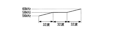
- FIG. 4 is a diagram illustrating an example of frequency modulation of a transmission signal in a simulation.
- 9 is a graph illustrating a correlation convolution integration result according to a first example of a simulation result. It is a graph which shows the correlation convolution integration result concerning the 2nd example of a simulation result.
- FIG. 11 is a diagram illustrating a processing configuration in a correlation processing unit and a correlation value summing unit corresponding to the operation example illustrated in FIG. 10. It is a figure showing an example of operation in a sonic processing device concerning one embodiment of the present invention.
- FIG. 13 is a diagram illustrating a processing configuration in a correlation processing unit and a correlation value summing unit corresponding to the operation example illustrated in FIG. 12. It is a figure showing composition of an ultrasonic system using a sonic processing device concerning a modification of the present invention.
- FIG. 11 is a diagram illustrating a processing configuration in a correlation processing unit and a correlation value summing unit corresponding to the operation example illustrated in FIG. 10. It is a figure showing composition of an ultrasonic system using a sonic processing device concerning a modification of the present invention.
- FIG. 3 is a diagram illustrating a configuration example of a random number generation circuit.
- FIG. 3 is a diagram illustrating an example of a frequency modulation table. It is a figure showing an example of application to a vehicle of an ultrasonic system. It is a figure showing an example of application to a vehicle of an ultrasonic system.
- FIG. 6 is a diagram illustrating a configuration of a self-wave detection system provided in an ultrasonic system according to a first comparative example.
- FIG. 20 is a diagram illustrating an example of a time transition of the output of the LPF in FIG. 19. It is a figure showing the composition of the self-wave detection system with which the ultrasonic system concerning a 2nd comparative example is provided.
- FIG. 6 is a diagram illustrating a configuration of a self-wave detection system provided in an ultrasonic system according to a first comparative example.
- FIG. 20 is a diagram illustrating an example of a time transition of the output of the LPF in FIG. 19. It is
- FIG. 22 is a diagram illustrating an example of a time transition of the output of the LPF in FIG. 21.
- FIG. 9 is a diagram for explaining an example of a correlation process.
- FIG. 9 is a diagram for explaining an example of a correlation process. It is a figure showing the composition of the ultrasonic system using the sonic processing device concerning one embodiment of the present invention. It is a figure showing composition of a self wave detection part contained in a sonic processing device concerning one embodiment of the present invention.
- FIG. 4 is a diagram illustrating a specific configuration of an all-section correlation convolution integration processing unit. It is a figure showing the concrete composition of the 1st section correlation convolution integral processing part and the 2nd section correlation convolution integral processing part.
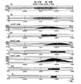
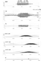
- 9 is a timing chart showing a first simulation result according to a comparative example.
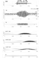
- 9 is a timing chart illustrating a second simulation result according to a comparative example.
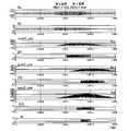
- 6 is a timing chart showing a first simulation result according to the embodiment of the present invention.
- 9 is a timing chart showing a second simulation result according to the embodiment of the present invention.
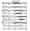
- 9 is a timing chart showing a third simulation result according to the embodiment of the present invention.
- 9 is a timing chart showing a fourth simulation result according to the embodiment of the present invention.
- 9 is a timing chart showing a fifth simulation result according to the embodiment of the present invention.
- 15 is a timing chart showing a sixth simulation result according to the embodiment of the present invention.
- FIG. 3 is a block diagram illustrating a configuration of a first ultrasonic system on a simulation.
- FIG. 3 is a block diagram illustrating a configuration of a first ultrasonic system on a simulation.
- 3 is a diagram illustrating a circuit configuration of a correlation processing unit. It is a figure showing the 1st example of the simulation result in the 1st ultrasonic system. 7 is a graph showing a calculation result of a correlation convolution integral value in a first example of a simulation result in a time series. It is a figure showing the 2nd example of the simulation result in the 1st ultrasonic system. 9 is a graph showing a calculation result of a correlation convolution integral value in a second example of a simulation result in a time series. It is a block diagram showing the composition of the 2nd ultrasonic system on simulation. It is a figure showing the 3rd example of the simulation result in the 2nd ultrasonic system.
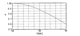
- FIG. 12 is a graph showing a calculation result of a correlation convolution integral value in a third example of a simulation result in a time series. It is a figure showing the 4th example of the simulation result in the 2nd ultrasonic system. It is the graph which showed the calculation result of the correlation convolution integral value in the 4th example of a simulation result in time series. It is a figure which shows an example of frequency modulation of transmission. It is a graph which shows the relationship between the gain of the correlation convolution integral value with the reference data of 0 km / h assumption, and receiving frequency. It is a graph which shows the relationship between the gain of the correlation convolution integral value with each reference data of 0 km / h, 10 km / h, and 20 km / h, and receiving frequency.
- FIG. 2 is a diagram illustrating an example of mounting an ultrasonic system including a plurality of sonication devices on a vehicle. It is a figure for explaining a problem caused by a Doppler effect. It is a figure for explaining a problem caused by a Doppler effect. It is a figure showing the composition of the ultrasonic system using the sonic processing device concerning the modification of a 1st embodiment. It is a figure showing the composition of the ultrasonic system using the sonic processing device concerning the modification of a 4th embodiment.
- the ultrasonic system according to the embodiment described below is assumed to be mounted on a vehicle as an example, and an alarm function, an automatic braking function, and an automatic parking function by measuring a distance between the vehicle and an object. Can be used for functions, etc.
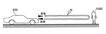
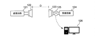
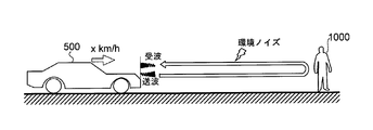
- FIG. 1 shows a vehicle 500 equipped with an ultrasonic system (not shown) and an object (obstacle) 1000.
- Ultrasonic waves transmitted from the ultrasonic system are reflected by the object 1000 and received as reflected waves by the ultrasonic system.
- the ultrasonic system also receives the environmental noise N.
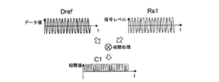
- reference data Dref is prepared in advance.
- the reference data Dref is waveform data of a reflected wave expected to be received, and has the same frequency as the frequency of a transmitted sound wave.
- the frequency of the received reflected wave Rs1 shown in FIG. 2 is the same as the transmission frequency. Therefore, in the correlation result C1 obtained by the correlation process of multiplying the reference data Dref and the reflected wave Rs1, the correlation value is always a positive value as shown in FIG. Thereby, the convolution integral value obtained by temporally integrating the correlation result C1 increases, and the reflected wave is emphasized.
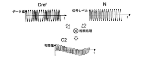
- the frequency of the received environmental noise N shown in FIG. 3 is shifted from the transmission frequency. That is, the frequency of the environmental noise N is shifted from the frequency of the reference data Dref. Therefore, as shown in FIG. 3, a period in which the correlation value is negative occurs in the correlation result C2, and the convolution integral value becomes smaller than that in FIG. In this way, it is possible to distinguish a reflected wave based on a transmitted wave from environmental noise.
- FIG. 4 is a block diagram showing a configuration of an ultrasonic system on a simulation.
- the ultrasonic system includes a transmission processing unit 100, a sound source 150, a reception processing unit 200, and a reception unit 250. That is, the transmission processing unit 100, the sound source 150, the reception processing unit 200, and the reception unit 250 are mounted on the vehicle 500 in FIG.
- the transmission processing unit 100 includes a transmission pattern generation circuit 100A, a transmission signal generation circuit 100B, a DA circuit 100C, and a reference data generation circuit 100D.
- the transmission pattern generation circuit 100A receives a transmission instruction and generates a transmission pattern.
- the transmission pattern generation circuit 100A can change the frequency and wave number of the generated transmission pattern. As described later, a chirp wave that has been subjected to frequency modulation as a transmission pattern can be generated.
- the transmission signal generation circuit 100B generates the transmission signal fout (t) based on the transmission pattern generated by the transmission pattern generation circuit 100A.
- the DA circuit 100C D / A converts the transmission signal fout (t) from a digital signal to an analog signal and outputs the signal to the sound source 150.
- the sound source 150 generates and transmits a sound wave based on the transmission signal converted into an analog signal.
- the reference data generation circuit 100D generates reference data according to the transmission pattern generated by the transmission pattern generation circuit 100A. Specifically, the reference data generation circuit 100D generates, as reference data, waveform data having the same frequency and the same wave number as the transmission signal fout (t).
- the reference data may be determined in consideration of the data accuracy, the data amount, and the like. For example, the reference data is data having five values (-1, -0.5, 0, 0.5, 1).
- the receiving unit 250 receives a sound wave and outputs a received signal to the AD circuit 200A. Note that, as shown in FIG. 1, it is possible to include environmental noise in the received signal in simulation. That is, a noise component can be included in a reflected wave of a sound wave transmitted from the sound source 150 and reflected by the object 1000.
- the AD circuit 200A A / D converts a received signal output from the receiving unit 250 from an analog signal to a digital signal and outputs the signal as a received signal fin (t).
- the correlation processing unit 200B performs a correlation process by multiplying the received signal fin (t) and the reference data Table sent from the reference data generation circuit 100D to the received signal processing unit 200.
- FIG. 5 is a diagram illustrating a circuit configuration of the correlation processing unit 200B.
- the correlation processing unit 200B includes a shift register SR, multiplication units M0 to Mn, and a reference data register Rg.
- the shift register SR has flip-flop groups DF0 to DFn.
- Each of the flip-flop groups DF0 to DFn is composed of D flip-flops having the number of bits of the received signal fin (t). For example, when the reception signal fin (t) has 12 bits, each of the flip-flop groups DF0 to DFn includes 12 D flip-flops.
- the flip-flop groups DF0 to DFn are arranged in order from the preceding stage.
- a reception signal fin (t) is input to an input terminal of the flip-flop group DF0.
- the output terminal of the preceding stage is connected to the input terminal of the subsequent stage.
- a clock signal CK is input to a clock terminal of each of the flip-flop groups DF0 to DF.
- each output of the flip-flop groups DF0 to DFn is bit-shifted from the former stage to the latter stage.
- Outputs fin (t-0) to fin (tn) of flip-flop groups DF0 to DFn are input to multipliers M0 to Mn, respectively.
- the reference data Table (0) to Table (n) stored in the reference data register Rg are also input to the multiplication units M0 to Mn. Therefore, the bit data of the received signals fin (t-0) to fin (tn) stored by the shift register SR and the reference data Table (0) to Table (n) are multiplied by the multiplication unit M0. Multiplied by Mn, correlation values fconv (t-0) to fconv (tn) are output.
- the number of (n + 1) is set based on the transmission time of the transmission signal and the sampling frequency of the reception signal, and is desirably set so as to capture at least the reception signal for the transmission time. .
- the correlation value summation unit 200C shown in FIG. 4 calculates the sum of the obtained correlation values fconv (t-0) to fconv (tn), thereby obtaining the correlation convolution integral value. Is output.
- a chirp wave having a center frequency of 58 kHz was used.
- the reference data is a chirp wave having the same frequency and the same wave number as the transmission signal.
- the receiving unit 250 receives the environmental noise together with the reflected wave of the ultrasonic wave transmitted from the sound source 150 based on the transmitted signal and the object 1000. Therefore, the received signal fin (t) has a waveform including the reflected wave component and the environmental noise component.
- the correlation processing unit 200B As a result of performing the correlation processing by multiplication of the received signal and the reference data by the correlation processing unit 200B, the correlation result is calculated, and the sum of the correlation results is calculated by the correlation value summation unit 200C, whereby the correlation convolution integration is performed. The value is output.
- FIG. 7 shows a calculation result of the correlation convolution integral value in a time series.
- the peak value of the correlation convolution integration value changes at a small value, and the correlation gradually increases from the timing at which the reflected wave based on the transmitted ultrasonic wave starts to be received.
- the peak value of the convolution integral value increases, and the peak value of the correlation convolution integral value becomes maximum at the timing (around 0 ⁇ s) when the entire reflected wave is captured by the shift register SR.
- the peak value of the correlation convolution integral value gradually decreases.
- the frequency modulation of the received signal based on the reflected wave does not deviate from the frequency modulation of the reference data. Therefore, by performing a correlation process on the reflected wave buried in noise with the reference data, the reflection is performed. Can amplify waves.
- FIG. 8 is a graph showing the result of performing the correlation convolution integration processing by the correlation processing unit 200B and the correlation value summation unit 200C based on the received signal and the reference data in this case.
- FIG. 8 is a diagram showing the correlation convolution integral value in a time series, similarly to FIG. Since the frequency of the received signal is a fixed value and the frequency is shifted from that of the frequency-modulated reference data, the peak of the correlation convolution integral value slowly changes while keeping the low level as shown in FIG.
- the reflected wave due to the ultrasonic wave transmitted from the own system can be distinguished from the ultrasonic wave transmitted from another system and detected. It is possible to do.
- the calculated convolution convolution integral value is compared with a predetermined threshold to detect a reflected wave due to its own transmission, thereby avoiding interference due to ultrasonic waves transmitted from another system. it can.
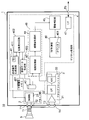
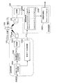
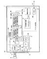
- FIG. 9 is a diagram showing a configuration of an ultrasonic system 10 using the sonic processing device 1 according to one embodiment of the present invention.
- the ultrasonic system 10 includes the ultrasonic processing device 1, the ultrasonic transmitting / receiving device 5, and the transformer Tr.
- the ultrasonic transmitting / receiving device 5 is externally connected to the sonic processing device 1 via a transformer Tr. Note that the transformer Tr is not necessarily provided.
- the sound wave processing device 1 is a semiconductor device having the driver unit 2, the analog front end 3, and the digital processing unit 4 integrated on one chip.
- the driver unit 2 has a DA circuit 21.
- the DA circuit 21 performs D / A conversion of the transmission signal output from the transmission signal generation circuit 41 included in the digital processing unit 4 from a digital signal to an analog signal.
- the DA circuit 21 is connected to the primary side of the transformer Tr via the external terminals T1 and T2.
- An ultrasonic transceiver 5 is connected to the secondary side of the transformer Tr1.
- the ultrasonic transmission / reception device 5 has a piezoelectric element (not shown) and transmits and receives ultrasonic waves. That is, the ultrasonic transmitting and receiving device 5 functions as both a sound source and a receiving unit.
- the analog front end 3 (received signal output unit) includes an LNA (low noise amplifier) 31, an LPF (low pass filter) 32, and an A / D converter 33.
- the primary side of the transformer Tr is connected to the LNA 31 via external terminals T3 and T4.
- the output of the LNA 31 is input to the A / D converter 33 via the LPF 32.
- the digital processing unit 4 includes a transmission signal generation circuit 41, a register 42, a correlation processing unit 43, a correlation value summation unit 44, a threshold determination unit 45, a TOF measurement unit 46, and a serial interface 47.
- the correlation processing section 43 and the correlation value summation section 44 constitute a correlation convolution integration processing section 48.
- the reference data is stored in the register 42.
- the correlation processing unit 43 performs a correlation process based on the received signal output from the A / D converter 33 and the reference data.
- the correlation value summation unit 44 outputs a correlation convolution integral value by calculating the sum of the correlation processing results by the correlation processing unit 43.
- the negative value of the calculated result may be a value obtained by truncating the negative value that is set to 0.
- the threshold determining unit 45 compares the correlation convolution integral value with a predetermined threshold. The details of the correlation processing unit 43, the correlation value summing unit 44, and the threshold value determination unit 45 will be described later.
- the TOF measuring unit 46 measures the time (TOF) from the transmission of the ultrasonic wave to the reception of the reflected wave due to the reflection on the target object, using the counter 461.
- the serial interface 47 conforms to LIN (Local Interconnect Network) as an example, and communicates with an external ECU (vehicle electronic control unit) (not shown) via an external terminal T5.
- LIN Local Interconnect Network
- ECU vehicle electronic control unit
- the transmission signal generation circuit 41 receives a transmission command from the ECU via the serial interface 47, the transmission signal generation circuit 41 outputs a transmission signal to the DA circuit 21. Thereby, the ultrasonic wave is transmitted from the ultrasonic transmission / reception device 5.
- the transmission signal generation circuit 41 generates a transmission signal configured by arranging a plurality of unit blocks each having a predetermined wave number in a time series, and performs frequency modulation for each unit block in the transmission signal. That is, the transmission signal generated by the transmission signal generation circuit 41 is a chirp wave.
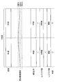
- FIG. 10 is a diagram illustrating an operation example of the sonic processing device 1.
- the transmission signal is configured by arranging eight unit blocks each including 16 waves, and includes a total of 128 waves.
- the frequency is maintained at 58 kHz in the first unit block, linearly increases from 58 kHz to 60 kHz in the second unit block, In the unit block of the eye, it linearly falls from 60 kHz to 58 kHz, in the fourth unit block, it falls linearly from 58 kHz to 56 kHz, in the fifth unit block, it rises linearly from 56 kHz to 58 kHz, and the sixth unit block It linearly drops from 58 kHz to 56 kHz in the unit block, linearly increases from 56 kHz to 58 kHz in the seventh unit block, and linearly increases from 58 kHz to 60 kHz in the eighth unit block.
- the center frequency is set to 58 kHz, and the frequency is maintained at 58 kHz in the first unit block, linearly decreases from 58 kHz to 56 kHz in the second unit block, and becomes 3 kHz.
- 56 kHz is maintained in the fifth unit block, linearly increases from 56 kHz to 58 kHz in the fourth unit block, linearly decreases from 58 kHz to 56 kHz in the fifth unit block, and 56 kHz in the sixth unit block.
- the frequency modulation of various patterns can be set by setting each pattern of ascending and descending to and maintaining each of fc, fc + ⁇ f, and fc ⁇ f for each unit block.
- the frequency modulation pattern is set so that the frequency changes continuously through all unit blocks. Setting such a frequency modulation pattern is equivalent to assigning an ID to the sonic processing device 1 (the ultrasonic system 10).
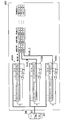
- the processing configuration in the correlation processing unit 43 and the correlation value summing unit 44 is as shown in FIG.
- the correlation processing unit 43 has a configuration in which shift registers SR1 to SR8 are connected in order from the previous stage.
- the A / D converter 33 arranges eight unit blocks each composed of 16 waves. The received wave signal is output.
- the shift register SR8 at the rearmost stage in FIG. 11 corresponds to the storage of the first unit block in the received signal
- the shift register SR7 at the previous stage corresponds to the storage of the second unit block in the received signal
- the first-stage shift register SR1 corresponds to the storage of the eighth unit block in the received signal.
- FIG. 11 shows reference data Dref1 to Dref8 corresponding to shift registers SR1 to SR8, respectively, and reference data Dref1 to Dref8 are stored in register 42.
- the reference data Dref1 to Dref8 have waveform data obtained by performing the same frequency modulation as the frequency modulation of each unit block of the transmission signal. That is, in the case of the first example of frequency modulation, for example, the reference data Dref8 has waveform data that has been subjected to frequency modulation while maintaining 58 kHz in the first unit block, and the reference data Dref1 has the eighth data. Has waveform data on which frequency modulation for linearly increasing from 58 kHz to 60 kHz in the unit block has been performed.
- the output from the D flip-flop group constituting each of the shift registers SR1 to SR8 is multiplied by the reference data Dref1 to Dref8 to calculate a correlation value. Then, the sum of the correlation values calculated for each of the shift registers SR1 to SR8 is calculated by each of the sum processing units 441 to 448, and the correlation convolution integral value is output.
- the sum processing units 441 to 448 are included in the correlation value sum unit 44.
- the correlation convolution integrated values output from each of the summation processing units 441 to 448 are compared with thresholds by the threshold determination unit 45, respectively.
- the threshold determination unit 45 determines that all correlation convolution integral values exceed the threshold, it is detected that a reflected wave based on the transmitted ultrasonic wave has been received. That is, it is detected that an ultrasonic wave matching the ID set in the own ultrasonic system 10 has been received.
- FIG. 10 shows a case where it is determined that all the correlation convolution integral values exceed the threshold value.
- the TOF measurement unit 46 starts counting by the counter 461 at the timing when the transmission command is issued, and counts when at least one correlation convolution integral value is equal to or less than the threshold value by the threshold value determination unit 45.
- the threshold determination unit 45 determines that all the correlation convolution integral values exceed the threshold value, the count value at that timing is held.
- the held count value corresponds to the TOF, and the distance to the target can be specified by the TOF and the sound speed.
- the held count value is sent to the ECU by the interface 47.
- the present embodiment when an ultrasonic wave transmitted from a system different from the own ultrasonic system 10 is received, a received signal different from the frequency modulation pattern that is the own ID is output. Therefore, it is determined that at least one correlation convolution integral value is smaller than the threshold value, and it is possible to avoid interference from another system.
- FIG. 12 shows another example of the operation of the sonic processing device 1.
- the total wave number of the transmitted signal is 128 waves, which is the same as that of FIG. 10 described above, but the wave number per unit block is 64 waves, which is larger than 16 waves in FIG. That is, a transmission signal is configured by arranging two unit blocks each composed of 64 waves.
- the frequency is linearly increased from 58 kHz to 60 kHz in the first unit block and linearly decreased from 60 kHz to 58 kHz in the second unit block.
- the frequency change in each unit block can be made gentler than in the case shown in FIG. 10, and it becomes possible to cope with the ultrasonic transmission / reception device 5 with low responsiveness.
- the number of unit blocks since the number of unit blocks is larger, the number of frequency modulation patterns can be increased. That is, the number of IDs that can be assigned can be increased.
- the processing configuration in the correlation processing unit 43 and the correlation value summing unit 44 is as shown in FIG.
- the correlation processing unit 43 has shift registers SR11 and SR12 each corresponding to storing a unit block of a received signal.
- the shift register SR12 is connected to the subsequent stage of the shift register SR11.
- Reference data Dref11 and Dref12 are prepared corresponding to the shift registers SR11 and SR12, respectively.
- the reference data Dref11 and Dref12 are stored in the register 42.
- the sum of the correlation processing results obtained by multiplying the output from the D flip-flop group constituting the shift register SR11 and the reference data Dref11 is calculated by the addition processing unit 4411, and the correlation convolution integral value is output.
- the sum of the correlation processing results obtained by multiplying the output from the D flip-flop group forming the shift register SR12 and the reference data Dref12 is calculated by the addition processing unit 4412, and the correlation convolution integral value is output.
- the sum processing units 4411 and 4412 are included in the correlation value sum unit 44.
- the threshold value determination unit 45 compares the correlation convolution integral value output from each of the addition processing units 4411 and 4412 with the threshold value.
- the total wave number of the transmission signal may be 128 waves, and the wave number of each unit block may be 8 waves or 128 waves.
- the transmission signal is composed of 16 unit blocks, and when the wave number of the unit block is 128, the transmission signal is composed of one unit block.
- the sound wave processing device 1 As a specification of the sound wave processing device 1, as described above, only one pattern among various patterns in which the wave number is changed in the unit block of the transmission signal may be supported. May be switched. That is, for example, the pattern shown in FIG. 10 and the pattern shown in FIG. 12 may be switched. In this case, the correlation processing unit 43, the correlation value summing unit 44, and the threshold value determination unit 45 need to switch the processing configuration shown in FIG. 11 or FIG. As a result, switching can be performed in accordance with the response performance of the externally attached ultrasonic transmission / reception device 5.
- switching may be performed, for example, by setting using an external terminal not shown in FIG. 9 or by setting from the ECU via the interface 47.
- the correlation convolution integration processing corresponding to one block (all sections) including all the unit blocks is performed. May go. For example, as shown in FIG. 10 and FIG. 11 described above, in addition to calculating a correlation convolution integral value for each 16-wave unit block, a correlation convolution integration value is calculated corresponding to one block of 128 waves. At this time, in addition to the configuration of the correlation convolution integral processing unit shown in FIG. 11, a configuration corresponding to storage of a block of 128 waves in the configuration shown in FIG. 5 is provided.
- the threshold determination unit 45 performs the threshold determination for each of the eight correlation convolution integral processing values obtained for each of the 16 wave unit blocks, and obtains the threshold for each of the 128 wave blocks. It is sufficient to provide an AND circuit that performs a threshold value determination for one correlation convolution integral value and calculates a logical product of the determination results of these threshold value determinations. Thereby, for example, when an ultrasonic wave having an ID different from that of the self is received, even if all the correlation convolution integral values exceed the threshold value in the threshold determination of the individual section, the correlation convolution integral value is not determined in the threshold determination of all sections. By falling below the threshold value, erroneous detection can be avoided, and the accuracy of the received wave determination can be further improved.
- FIG. 14 is a diagram showing a configuration of an ultrasonic system 10 using a sonic processing device 1 according to a modification of the present invention.
- the sound wave processing device 1 illustrated in FIG. 14 includes a nonvolatile memory 401, a random number generation circuit 402, and a reference data setting unit 403.
- FIG. 15 is a diagram showing a configuration example of the random number generation circuit 402.
- the random number generation circuit 402 shown in FIG. 15 has LFSRs (linear feedback shift registers: linear feedback shift registers) 402A to 402C.
- the LFSR is an example of a pseudo-random number generation circuit, and is a shift register to which exclusive OR of bits from a plurality of predetermined bit positions is input to one end.
- a 16-bit shift register in which the exclusive OR of bits from each bit position of the 16th, 14th, 13th, and 11th bits is input to one end It has become.
- a database DB is composed of the register 42 and the nonvolatile memory 401.
- the nonvolatile memory 401 stores an initial value.
- the initial value is set to a value other than 00.
- the initial values stored in the nonvolatile memory 401 are read into the LFSRs 402A to 402C.
- the data of the shift register is shifted every time a clock pulse (not shown) is input, so that the 16-bit data is rewritten and a random number is generated.
- the data of the LFSR 402A is read from the bus BUS_A and obtained as 16-bit data of bit data BUS_A_1 to BUS_A_16.
- the data of the LFSR 402B is read from the bus BUS_B and obtained as 16-bit data of the bit data BUS_B_1 to BUS_B_16.
- the data of the LFSR 402C is read from the bus BUS_C and obtained as 16-bit data of bit data BUS_C_1 to BUS_C_16. That is, random data of 16 bits ⁇ 3 columns is generated.
- the transmission signal generation circuit 41 (FIG. 14) has a frequency modulation table 411 as shown in FIG. 16, for example.
- the frequency modulation table 411 defines a correspondence between a combination of bit data and a frequency modulation pattern in the same modulation section.
- FIG. 16 shows a first modulation example and a second modulation example as an example as a frequency modulation pattern.
- the frequency is maintained at 56 kHz. , From 56 kHz to 58 kHz.
- the transmission signal generation circuit 41 generates a transmission signal modulated in each modulation section (each unit block) by the random number data generated by the random number generation circuit 402 and the frequency modulation pattern determined based on the frequency modulation table 411. I do. For example, when one modulation section is composed of eight waves, a transmission signal of 128 waves is generated.
- the reference data setting unit 403 sets the reference data modulated by the frequency modulation pattern determined based on the random number data generated by the random number generation circuit 402 in the register 42.
- the frequency modulation pattern here is the same as the pattern determined by the frequency modulation table 411 described above.
- a transmission signal with a different ID is generated between vehicles of the same vehicle type equipped with the sonic processing device 1, and interference due to transmission from a vehicle different from the own vehicle can be suppressed.
- the input clock pulses are asynchronous with each other.
- the initial value to be stored in the nonvolatile memory 401 is common to each individual of the sound wave processing apparatus 1, the initial value is read out to the LFSRs 402A to 402C and the same random number is generated among the individuals when the first random number data is generated. Data is generated.
- the time until reception is different between individuals depending on the flight time of the transmitted ultrasonic wave, and the random number data generated at the next transmission after detection of the reception is There is a high possibility that it differs between individuals.
- the initial value stored in the nonvolatile memory 401 be different between individuals.
- the initial value is not limited to be common to the LFSRs 402A to 402C, and may be different from each other for the LFSRs 402A to 402C.
- the operation of the LFSRs 402A to 402C is started by the clock pulse, and when a disable signal is input, the operations of the LFSRs 402A to 402C are stopped.
- the data of 402C may be obtained as random number data. In this case, it is preferable that the period from the input of the enable signal to the input of the disable signal differs between individuals. Further, the period may be sequentially changed in the same individual as time elapses.
- FIG. 17 schematically illustrates a vehicle 20 equipped with the ultrasonic system 10 including the sonic processing device 1 according to the present embodiment.
- the ultrasonic system 10 is disposed at a rear end 201 (for example, a rear bumper) of the vehicle 20, and the ultrasonic system 10 is used as a rear sensor.
- the ultrasonic wave transmitted from the ultrasonic system 10 is reflected by the object and received by the ultrasonic system 10 as a reflected wave.
- the ultrasonic wave W may be transmitted from another ultrasonic system mounted on a vehicle 25 different from the vehicle 20.
- the ultrasonic wave W has a frequency different from the frequency modulation pattern as the ID set in its own ultrasonic system 10, so the correlation convolution integration processing
- the threshold determination unit 45 By the determination by the threshold determination unit 45, interference by the ultrasonic wave W from another ultrasonic system can be avoided.
- the ultrasonic system 10 may be used as a front sensor by, for example, being arranged at the front end (for example, a front bumper) of the vehicle 20.
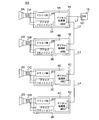
- FIG. 18 shows a state in which a plurality of ultrasonic systems including the ultrasonic system 10 are mounted on the front end of the vehicle 30.
- ultrasonic systems 301 to 303 are mounted on the vehicle 30.
- Each of the ultrasonic system 10 and the ultrasonic systems 301 to 303 may sequentially transmit the ultrasonic waves and measure the TOF, but in that case, the frequency of the distance measurement to the object decreases, and for example, the vehicle 30 May unnecessarily approach the object.
- the ultrasonic system 10 and the ultrasonic systems 301 to 303 perform ultrasonic wave transmission and TOF measurement in parallel.
- the ultrasonic waves transmitted from the ultrasonic system 10 are transmitted from the other ultrasonic systems 301 and 302 in addition to the reflected waves reflected by the object 61.
- the ultrasound system 10 receives the reflected waves of the ultrasonic waves reflected by the objects 62 and 63, respectively.
- the correlation convolution integration processing and the threshold By the determination by the determination unit 45, interference by ultrasonic waves from the other ultrasonic systems 301 and 302 can be avoided.
- the reflected wave (self) based on the ultrasonic wave transmitted from the own ultrasonic system depends on whether or not the correlation convolution integral value calculated by the correlation convolution integration processing exceeds a predetermined threshold value. (Wave) or ultrasonic waves (other waves) transmitted from another ultrasonic system can be distinguished.
- the calculated correlation convolution integration value should originally have a threshold value. Does not exceed. However, if the frequency of the signal received by another wave is near the resonance frequency, the amplitude of the received signal will increase, and the correlation convolution integral value will increase, exceeding the threshold value, erroneously detecting that the own wave has been received. Was likely to occur. Also, when another wave is received from another system that is close in distance, the amplitude of the received signal increases, and the same problem may occur.
- FIG. 1 described above shows a vehicle 500 equipped with an ultrasonic system (not shown) and an object (obstacle) 1000.
- Ultrasonic waves transmitted from the ultrasonic system are reflected by the object 1000 and received by the ultrasonic system as reflected waves (own waves).
- the ultrasonic system measures the distance from the transmission of the ultrasonic wave to the reception of its own wave due to reflection at the object 1000 (TOF), thereby measuring the distance to the object.
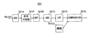
- FIG. 19 is a diagram illustrating a configuration of the own-wave detection system 101 provided in the ultrasonic system according to the first comparative example.
- a self-wave detection system 101 shown in FIG. 19 includes an ADC (AD converter) 101A, a BPF (bandpass filter) 101B, an absolute value extraction unit 101C, an LPF (low-pass filter) 101D, a comparator 101E, and a sign addition unit. 101F.
- ADC AD converter
- BPF bandpass filter
- LPF low-pass filter
- comparator 101E comparator
- sign addition unit. 101F sign addition unit.
- the ADC 101A receives a received signal Rs101 that is output by receiving an ultrasonic wave by an ultrasonic receiving device (not shown) included in the ultrasonic system, A / D converts the received received signal Rs101, and performs digital conversion.
- the signal is output to sign adding section 101F.
- the sign adding unit 101F adds positive and negative signs to the input digital signal by performing a level shift so that the center becomes 0.
- the digital signal to which the code has been added is input to the BPF 101B.
- a signal in a specific range of frequencies is extracted by the BPF 101B, an absolute value is extracted by the absolute value extracting unit 101C, and a low frequency component is extracted by the LPF 101D.
- the comparator 101E compares the output of the LPF 101D with the threshold Th101.
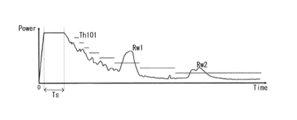
- FIG. 20 is a diagram illustrating an example of a time transition of the output of the LPF 101D.
- FIG. 20 shows a case where the ultrasonic receiving device in the ultrasonic system also has a configuration for transmitting ultrasonic waves.
- the ultrasonic receiver transmits an ultrasonic wave
- a reception signal is generated by the transmission at the same time, and the output of the LPF 101D rises sharply and is maintained at a high level during the transmission time Ts.
- the output of the LPF 101D is generated by receiving reverberation immediately after transmission or noise due to irregular reflection from the ground or the like, but the reverberation and noise level attenuate as time elapses. Therefore, the output of the LPF 101D also decreases as time elapses.
- the level of the received own wave attenuates as the transmitted ultrasonic wave travels in the atmosphere for a longer time.
- the threshold value Th101 used by the comparator 101E is set so as to decrease as time passes.
- the comparator 101E detects that the output of the LPF 101D has risen and has exceeded the threshold value Th101. Can be detected.
- FIG. 21 is a diagram illustrating a configuration of the own-wave detection system 102 provided in the ultrasonic system according to the second comparative example.
- ⁇ Self-wave detection system 102 shown in FIG. 21 includes ADC 102A, correlation convolution integral processing section 102B, LPF 102C, comparator 102D, and sign adding section 102E.
- the ADC 102A receives a received signal Rs102, which is output by receiving an ultrasonic wave by an ultrasonic receiving device (not shown) included in the ultrasonic system, A / D converts the received signal Rs102, and encodes the code. Output to addition section 102E.
- the sign adding unit 102E adds positive and negative signs by level-shifting the input digital signal so that the center becomes 0.
- the digital signal to which the sign has been added is input to the correlation convolution integral processing unit 102B.
- reference data Dref is prepared in advance.
- the reference data Dref is waveform data of a reflected wave (own wave) expected to be received, and has the same frequency as the frequency of the transmitted ultrasonic wave.
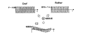
- the received received signal Rself shown in FIG. 23 is a received signal when the own wave is received, and the frequency of the received signal Rself is the same as the transmission frequency, that is, the frequency of the reference data Dref. Therefore, in the correlation result C1 obtained by the correlation process of multiplying the reference data Dref and the received signal Rself, the correlation value is always a positive value as shown in FIG.
- the received signal Rother shown in FIG. 24 is a received signal when another wave is received, and the frequency of the received signal Rother is shifted from the transmission frequency, that is, the frequency of the reference data Dref. Therefore, as shown in FIG. 24, in the correlation result C2, a period in which the correlation value is negative occurs.
- the correlation convolution integral value obtained by temporally integrating the correlation value is also different. This makes it possible to distinguish the own wave from other waves.
- the correlation convolution integral processing section 102B performs convolution integral processing based on the digital signal input from the sign adding section 102E and the reference data, and a value of 0 or more in the convolution integral value obtained by the processing is a negative value. Outputs the processing result of 0 to the LPF 102C. That is, the correlation convolution integral processing unit 102B rounds down the negative value of the obtained convolution integral value.
- the LPF 102C performs a filtering process on the input processing result to extract a low frequency component.
- the comparator 102D compares the output of the LPF 102C with the threshold Th102, and outputs a comparison result.
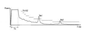
- FIG. 22 is a diagram showing an example of a time transition of the output of the LPF 102C.
- FIG. 22 shows a case where the ultrasonic receiving device in the ultrasonic system also has a configuration for transmitting an ultrasonic wave.
- the ultrasonic receiver transmits an ultrasonic wave
- a reception signal is generated at the same time as the transmission, and the output of the LPF 102C sharply rises and is maintained at a high level during the transmission time Ts.
- the output of the LPF 102C is generated by receiving reverberation immediately after transmission or noise due to irregular reflection from the ground or the like, but the reverberation and noise level attenuate as time passes. Therefore, the output of the LPF 102C also decreases as time passes. On the other hand, the level of the received own wave attenuates as the transmitted ultrasonic wave travels in the atmosphere for a longer time.
- the threshold value Th102 used by the comparator 102D is set so as to decrease as time passes. Thereby, as shown in FIG. 22, for example, when the own wave Rw1 or the own wave Rw2 is received, the comparator 102D detects that the output of the LPF 102C has risen and has exceeded the threshold value Th102. Can be detected.
- the received signal having a frequency different from its own transmission frequency and having a level equal to or lower than the level of the received signal when receiving the own wave attenuated by the attenuation degree at the current elapsed time is received.
- the output of the LPF 102C does not exceed the threshold Th102, so that the own wave and the other wave can be distinguished.
- the output of the LPF 102C becomes the threshold Th102. Erroneous detection may occur when the own wave is received.
- Such a case is, for example, a case where another wave near the resonance frequency is received, or a case where another wave is received from another system located at a short distance from itself.
- the threshold value Th102 needs to be set in accordance with the passage of time as in the first comparative example, and there is a problem that the threshold value setting is not easy.
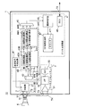
- FIG. 25 is a diagram showing a configuration of an ultrasonic system 10 using the sonic processing device 1 according to one embodiment of the present invention.
- the ultrasonic system 10 includes the ultrasonic processing device 1, the ultrasonic transmitting / receiving device 5, and the transformer Tr.
- the ultrasonic transmitting / receiving device 5 is externally connected to the sonic processing device 1 via a transformer Tr. Note that the transformer Tr is not necessarily provided.
- the sound wave processing device 1 is a semiconductor device having the driver unit 2, the analog front end 3, and the digital processing unit 4 integrated on one chip.
- the driver unit 2 has a DA circuit 21.
- the DA circuit 21 performs D / A conversion of the transmission signal output from the transmission signal generation circuit 41 included in the digital processing unit 4 from a digital signal to an analog signal.
- the DA circuit 21 is connected to the primary side of the transformer Tr via the external terminals T1 and T2.
- An ultrasonic transceiver 5 is connected to the secondary side of the transformer Tr1.
- the ultrasonic transmission / reception device 5 has a piezoelectric element (not shown) and transmits and receives ultrasonic waves. That is, the ultrasonic transmitting and receiving device 5 functions as both a sound source and a receiving unit.
- the analog front end 3 has an LNA (low noise amplifier) 31, an LPF 32, and an ADC 33.
- the primary side of the transformer Tr is connected to the LNA 31 via external terminals T3 and T4.
- the output of the LNA 31 is input to the ADC 33 via the LPF 32.
- the digital processing unit 4 includes a transmission signal generation circuit 41, a sign addition unit 42, a clipping unit 43, a register 44, a correlation convolution integration processing unit 45, a threshold determination unit 46, a TOF measurement unit 47, a serial An interface 48.
- the ADC 33 converts a received signal as an analog signal generated on the primary side of the transistor Tr into a digital received signal Rd1, which is digital data of a first predetermined number of bits, and outputs it.
- the digital received signal Rd1 is data of 0 or more. If the first predetermined number of bits is, for example, 12 bits, the digital received signal Rd1 is data of 0 to 4095.
- the sign adding unit 42 shifts the level so that a positive or negative sign is added to the digital received signal Rd1, and outputs the digital received signal Rd2.
- the digital reception signal Rd1 is 12-bit data of 0 to 4095
- the digital reception signal shifted to data of ⁇ 2047 to ⁇ 1, 0, +1 to +2047 (that is, center 0).
- the wave signal Rd2 is output.
- the method of level shifting the data by the sign adding unit 42 is not limited to this.
- the analog front end 3 and the sign addition unit 42 constitute an example of a reception signal output unit.
- the clipping unit 43 limits the digital reception signal Rd2 input from the sign addition unit 42 to the maximum value or less and the minimum value or more of the expression value in the second predetermined number of bits, and outputs the clipping data Rc after the limitation.
- the second predetermined number of bits is smaller than the first predetermined number of bits. That is, when the digital reception signal Rd2 is equal to or more than the maximum value of the expression value in the second predetermined number of bits, the clipping unit 43 sets the clipping data Rc to the maximum value and sets the digital reception signal Rd2 to the second predetermined number of bits. If the expression value is not more than the minimum value, the clipping data Rc is set to the minimum value.
- the digital reception signal Rd2 of ⁇ 2047 to ⁇ 1, 0, +1 to +2047 becomes ⁇ 16 to ⁇ 1, It is limited to clipping data Rc of +1 to +16.
- the digital received signal Rd1 of ⁇ 2047 to ⁇ 1, 0, +1 to +2047 is clipped by ⁇ 1 or +1. Limited to data Rc.
- the register 44 stores reference data.
- the correlation convolution integral processing unit 45 includes a correlation processing unit 45A and a correlation value summing unit 45B.
- the correlation processing unit 45A performs a correlation process of multiplying the clipping data Rc of a predetermined section by the reference data.
- the correlation value summing unit 45B outputs the correlation convolution integral value by calculating the sum of the correlation processing results by the correlation processing unit 45A.
- the threshold determination unit 46 detects the own wave by performing a threshold determination process based on the correlation convolution integral value. The details of the correlation convolution integral processing unit 45 and the threshold value judgment unit 46 will be described later.
- the TOF measuring unit 47 uses the counter 471 to measure a time (TOF) from transmission of an ultrasonic wave to reception of a reflected wave due to reflection on an object.
- TOF time
- the serial interface 48 is compliant with, for example, LIN (Local Interconnect Network) and communicates with an external ECU (vehicle electronic control unit) (not shown) via an external terminal T5.
- LIN Local Interconnect Network
- the transmission signal generation circuit 41 receives a transmission command from the ECU via the serial interface 48, the transmission signal generation circuit 41 outputs a transmission signal to the DA circuit 21. Thereby, the ultrasonic wave is transmitted from the ultrasonic transmission / reception device 5.
- the TOF measuring unit 47 starts counting by the counter 471 at the timing when the wave transmission command is issued, and continues counting while the threshold determining unit 46 does not determine that the own wave is detected. When it is determined that the own wave has been detected, the count value at that timing is held. The held count value corresponds to the TOF, and the distance to the target can be specified by the TOF and the sound speed. The held count value is sent to the ECU by the interface 48.
- FIG. 26 is a diagram illustrating a configuration of the own wave detection unit 400 included in the sonic processing device 1.
- the own-wave detecting section 400 shown in FIG. 26 includes a sign adding section 42, a clipping section 43, a first section correlation convolution integral processing section 451, a second section correlation convolution integral processing section 452, and a full section correlation convolution integral processing.
- the first section correlation convolution integral processing section 451, the second section correlation convolution integral processing section 452, and the full section correlation convolution integral processing section 453 are included in the correlation convolution integral processing section 45 shown in FIG.
- the first threshold value comparing unit 461, the second threshold value comparing unit 462, the third threshold value comparing unit 463, and the AND unit 464 are included in the threshold value determining unit 46 shown in FIG.
- the first section reference data 441, the second section reference data 442, and the entire section reference data 443 shown in FIG. 9 are stored in the register 44 shown in FIG.
- the ultrasound transmitted from the ultrasound system 10 includes a second section having a second predetermined frequency at a second predetermined frequency, and a second section having a first predetermined frequency immediately after the second section.
- the first section reference data 441 is waveform data of a first predetermined frequency at a first predetermined frequency
- the second section reference data 442 is waveform data of a second predetermined wave number at a second predetermined frequency.
- the first section correlation convolution integral processing section 451 sequentially captures the first section in the clipping data Rc, and performs the correlation convolution integration processing based on the acquired data of the first section and the first section reference data 441.
- the first section correlation convolution integral processing section 451 outputs the correlation convolution integral value conv1_sum obtained by the processing to the first threshold comparing section 461.
- the second section correlation convolution integral processing section 452 is disposed after the first section correlation convolution integral processing section 451, sequentially acquires the second section in the clipping data Rc, and acquires the acquired second section data and second section reference data. 442 to perform a correlation convolution integration process.
- the second section correlation convolution integral processing section 452 outputs the correlation convolution integral value conv2_sum obtained by the processing to the second threshold comparing section 462.
- All section reference data 443 is waveform data in which first section reference data 441 and second section reference data 442 are arranged.
- the whole section correlation convolution integral processing section 453 sequentially takes in all sections consisting of the first section and the second section in the clipping data Rc, and performs correlation convolution integration processing based on the taken whole section data and all section reference data 443. I do.
- the all-section correlation convolution integral processing unit 453 outputs the correlation convolution integral value conv3_sum obtained by the processing to the third threshold comparing unit 463.
- FIG. 27 is a diagram illustrating a specific configuration of the all-period correlation convolution integration processing unit 453.
- the whole section correlation convolution integral processing unit 453 includes a correlation processing unit 453A and a correlation value summation unit 453B.
- the correlation processing unit 453A has a shift register SR and multiplication units M0 to Mn.
- the shift register SR has flip-flop groups DF0 to DFn.
- Each of the flip-flop groups DF0 to DFn includes D flip-flops having the number of bits of the input signal fin (t).
- the input signal fin (t) is clipping data Rc.
- each of the flip-flop groups DF0 to DFn includes five D flip-flops. . Since the number of bits is limited by the clipping data Rc, the number of D flip-flops to be used can be reduced.
- the flip-flop groups DF0 to DFn are arranged in order from the preceding stage.
- the input signal fin (t) is input to the input terminal of the flip-flop group DF0.
- the output terminal of the preceding stage is connected to the input terminal of the subsequent stage.
- a clock signal CK is input to a clock terminal of each of the flip-flop groups DF0 to DF.
- each output of the flip-flop groups DF0 to DFn is bit-shifted from the former stage to the latter stage.
- Outputs fin (t-0) to fin (tn) of flip-flop groups DF0 to DFn are input to multipliers M0 to Mn, respectively.
- all-section reference data 443 (Table (0) to Table (n)) stored in the register 44 is also input to the multiplication units M0 to Mn. Therefore, the bit data of the input signals fin (t-0) to fin (tn) stored by the shift register SR and the reference data Table (0) to Table (n) of the entire section are multiplied by the multiplication unit. Multiplied by M0 to Mn, correlation values fconv (t-0) to fconv (tn) are output. Since the number of bits is limited by the clipping data Rc, the circuit size of the multiplier can be reduced.
- the (n + 1) numbers correspond to a wave number that is the sum of the first predetermined wave number and the second predetermined wave number.
- FIG. 27 shows a case where both the first predetermined wave number and the second predetermined wave number are 16 waves as an example.
- the correlation value summation unit 453B outputs the correlation convolution integral value conv3_sum by calculating the sum of the obtained correlation values fconv (t-0) to fconv (tn).
- the all-period correlation convolution integral processing unit 453 outputs a correlation convolution integral value conv3_sum which is a value of 0 or more in the correlation convolution integral value obtained as described above and a negative value of 0 as a correlation convolution integral value conv3_sum. That is, the whole section correlation convolution integral processing section 453 rounds down the negative value of the obtained correlation convolution integral value.
- FIG. 28 is a diagram showing a specific configuration of the first section correlation convolution integral processing section 451 and the second section correlation convolution integration processing section 452.
- the first section correlation convolution integral processing section 451 includes a correlation processing section 451A and a correlation value summing section 451B.
- the correlation processing unit 451A has a shift register SR1.
- the number of D flip-flop groups included in shift register SR1 corresponds to the first predetermined wave number.
- FIG. 28 shows a case where both the first predetermined wave number and the second predetermined wave number are 16 waves as an example.
- the second section correlation convolution integral processing section 452 includes a correlation processing section 452A and a correlation value summing section 452B.
- the correlation processing unit 452A has a shift register SR2.
- the number of D flip-flop groups included in shift register SR2 corresponds to the second predetermined wave number.
- the shift register SR2 is connected to the subsequent stage of the shift register SR1.
- the correlation processing unit 451A multiplies the captured first section clipping data Rc by the first section reference data 441.
- the correlation value summation unit 451B outputs the correlation convolution integral value conv1_sum by calculating the sum of the correlation values obtained by the multiplication of the correlation processing unit 451A.
- the correlation processing unit 452A multiplies the captured second section clipping data Rc by the second section reference data 442.
- the correlation value summation unit 452B outputs the correlation convolution integral value conv2_sum by calculating the sum of the correlation values obtained by the multiplication of the correlation processing unit 452A.
- the first section correlation convolution integral processing section 451 and the second section correlation convolution integration processing section 452 each set the value of the correlation convolution integral value obtained as described above equal to or greater than 0 to 0, and the negative value to 0.
- the processing results are output as correlation convolution integral values conv1_sum and conv2_sum. That is, the first section correlation convolution integral processing section 451 and the second section correlation convolution integral processing section 452 round down negative values of the obtained correlation convolution integral values.
- the first threshold comparing unit 461 compares the correlation convolution integral value conv1_sum with a predetermined first threshold Th1, and outputs a comparison result CP1.
- the comparison result CP1 becomes High; otherwise, the comparison result CP1 becomes Low.
- the second threshold comparing unit 462 compares the correlation convolution integral value conv2_sum with a predetermined second threshold Th2, and outputs a comparison result CP2.
- the comparison result CP2 becomes High; otherwise, the comparison result CP2 becomes Low.
- the third threshold value comparing unit 463 compares the correlation convolution integral value conv3_sum with a predetermined third threshold value Th3, and outputs a comparison result CP3.
- the comparison result CP3 becomes High; otherwise, the comparison result CP3 becomes Low.
- AND section 464 outputs the logical product of comparison results CP1, CP2, and CP3 as determination result A1.
- the comparison result A1 becomes High, it is determined that the own wave has been detected.
- Simulation verification> A simulation was performed to verify the effect of the self wave detection unit 400 according to the present embodiment.
- FIG. 29 shows a transmission / reception system for actually measuring a received signal.
- the transmission sensor 122 and the reception sensor 123 are arranged at an interval of a predetermined distance D.
- the transmission sensor 122 was driven by the transmission circuit 121, and the transmission sensor 122 transmitted ultrasonic waves.
- the transmitted ultrasonic wave was received by the reception sensor 123, the sensor voltage of the reception sensor 123 was measured by the oscilloscope 125, and the measurement result was stored as actually measured waveform data.
- the simulation was performed by reading the stored measured waveform data into the simulation environment 126.
- FIG. 30 and FIG. 31 show the results of a simulation performed for comparison with the present embodiment, specifically, the results in the case where clipping of a digital received signal is not performed. That is, in this case, the digital reception signal Rd is input to each correlation convolution integration processing unit.
- the first predetermined frequency and the second predetermined frequency are both 56 kHz, and the first predetermined wave number and the second predetermined wave number are both 16 waves.
- FIG. 30 shows an example in which the second predetermined frequency is set to 56 kHz and the second predetermined wave number is set to 16 in the second section, and the first predetermined frequency is set to 56 kHz and the first predetermined wave number is set to 16 in the first section.
- This is a result of reading the actually measured waveform data Rv obtained in the case into the simulation environment. That is, FIG. 30 shows a simulation result when the own wave is received.
- a place where the amplitude is large in the measured waveform data Rv indicates a place where the transmitted ultrasonic wave is received.
- Correlation convolution integrals conv1_sum and conv3_sum start rising near the timing at which the transmitted ultrasonic wave starts to be received, and receive the first section and receive the second section of the transmitted ultrasonic wave.
- the correlation convolution integral value conv2_sum starts rising near the timing of starting the wave. Then, near the timing when all the transmitted ultrasonic waves are received, the correlation convolution integral values conv1_sum to conv3_sum are all near the maximum value.
- the first threshold Th1 and the second threshold Th2 are equal, and the third threshold Th3 is twice the first threshold Th1. Value.
- the correlation convolution integral values conv1_sum to conv3_sum all have periods exceeding the first to third threshold values Th1 to Th3, and a period occurs in which the comparison results CP1 to CP3 are all High, so that the determination result A1 is obtained. Also, there is a period during which the signal becomes High. Therefore, it can be determined that the own wave has been detected.
- FIG. 31 shows an ultrasonic wave in which the second predetermined frequency is 58 kHz and the second predetermined wave number is 16 in the second section, and the first predetermined frequency is 58 kHz and the first predetermined wave number is 16 in the first section.
- the second predetermined frequency is 58 kHz and the second predetermined wave number is 16 in the second section
- the first predetermined frequency is 58 kHz and the first predetermined wave number is 16 in the first section.
- FIGS. 32 and 33 are timing charts showing simulation results according to the present embodiment corresponding to FIGS. 30 and 31 according to the comparative example described above.
- the measured waveform data Rv shown in FIG. 32 and FIG. 33 are the same as those in FIG. 30 and FIG. 31, respectively.
- the digital received signal Rd shown in FIGS. 30 and 31 was clipped, and clipping data Rc was input to each correlation convolution integral processing unit. Specifically, as an example, clipping was performed so as to limit the 12-bit digital received signal Rd to 5 bits (that is, -16 to -1, +1 to +16).
- each of the correlation convolution integral values conv1_sum to conv3_sum has a period exceeding the first threshold Th1 to the third threshold Th3, and the determination result A1 A High period occurs, and it can be determined that the own wave has been detected.
- FIG. 33 unlike FIG. 31, even if the amplitude of the measured waveform data Rv is large because 58 kHz is near the resonance frequency, the amplitude of the clipping data Rc is limited. And the frequency of the reference data, the correlation convolution integral values conv1_sum and conv2_sum exceed the first threshold value Th1 and the second threshold value Th2, but the correlation convolution integral value conv3_sum does not have a period exceeding the third threshold value Th3. There is no High period in the result A1, and it is possible to avoid erroneous determination that the own wave has been detected.
- the amplitude of the digital received signal is limited by clipping and then the correlation convolution integration process is performed. Therefore, another wave near the resonance frequency is received at a frequency different from its own transmission frequency.
- the correlation convolution integral value is set to the threshold value. Can be suppressed, and erroneous determination that the own wave has been detected can be avoided.
- the received signal generated by the environmental noise or the transmitted ultrasonic wave is clipped without depending on the environmental noise or the attenuation with time of the transmitted ultrasonic wave, so that the correlation convolution integral value and There is no need to set a threshold value for comparison with the passage of time, and the threshold value can be easily set.
- the ultrasonic wave to be transmitted is divided into two sections, and each section has 16 waves having the same wave number.
- the threshold set by the correlation convolution integral processing section for each section is the same, and the threshold set by the correlation convolution integration processing section for all sections is the threshold of the above section.
- a threshold value can be easily set as the number of sections.
- the correlation convolution integral processing units for each of the divided sections in series (FIG. 28)
- the correlation convolution integral value starts to exceed or fall below the threshold value for each section as shown in FIG. Since the timing is shifted, the own wave detection period can be shortened as a result of the AND operation.
- FIGS. 34 and 35 show the simulation results when clipping is limited to one bit, corresponding to FIGS. 32 and 33.
- FIG. Therefore, in FIGS. 34 and 35, the clipping data Rc is limited to a value of either ⁇ 1 or +1.
- the correlation convolution integral values conv1_sum to conv3_sum all exceed the first to third threshold values Th1 to Th3, and a period in which the determination result A1 becomes High occurs, and it is determined that the own wave has been detected. is made of.
- the correlation convolution integral value conv3_sum does not exceed the third threshold value, and the correlation convolution integral values conv1_sum and conv2_sum do not exceed the first threshold value Th1 and the second threshold value Th2. In the result A1, no High period occurs, and erroneous determination of own wave detection can be avoided.
- FIGS. 36 and 37 show simulation results when clipping is limited by one bit, as in FIGS. 34 and 35.
- the difference from FIG. 34 and FIG. The difference from FIG. 34 and FIG. , The second predetermined frequency is 56 kHz, the first predetermined frequency is 60 kHz, and both the first predetermined wave number and the second predetermined wave number are 16 waves.
- the second predetermined frequency is 56 kHz
- the second predetermined wave number is 16 waves
- the first predetermined frequency is 60 kHz and the first predetermined wave number is 16 waves in the first section.
- the period in which the correlation convolution integral values conv1_sum to conv3_sum exceed the first threshold value Th1 to the third threshold value Th3 is shortened, and the period in which the determination result A1 becomes High is shortened.
- the detection period can be further shortened. In this manner, by performing modulation with a different frequency for each section, the own wave detection period can be further reduced.
- FIG. 37 shows an example in which the second predetermined frequency is 58 kHz and the second predetermined wave number is 16 in the second section, and the first predetermined frequency is 58 kHz and the first predetermined wave number is 16 in the first section. This is a result of reading the actually measured waveform data Rv obtained in the case of waving into a simulation environment. That is, FIG. 37 shows a simulation result when another wave is received.
- the correlation convolution integral values conv1_sum to conv3_sum do not exceed the first to third threshold values Th1 to Th3, and a period in which the determination result A1 is High does not occur, thereby preventing erroneous determination of own wave detection.
- this embodiment may be implemented in combination with the first embodiment. That is, more specifically, a clipping unit may be added to the sonicator 1 according to the first embodiment shown in FIG. In this case, the clipping data generated by the clipping unit may be input to the correlation processing unit 43. Accordingly, in an embodiment in which frequency modulation can be performed for each unit block of a transmission signal, correlation convolution integration processing can be performed for each unit block based on clipping data generated from a reception signal.
- the ultrasonic system 10 including the sonic processing device 1 according to the present embodiment may be mounted on the vehicle 20 shown in FIG. 17 or the ultrasonic system shown in FIG. You may apply to a system.
- the ultrasonic wave transmitted from the ultrasonic system mounted on the vehicle 500 is reflected by the object (obstacle) 1000 and received by the ultrasonic system as a reflected wave. (F1 in FIG. 38).
- the transmitted ultrasonic wave may be reflected on a road surface and received as a reflected wave (F2 in FIG. 38).
- FIG. 39 is a diagram showing an example of extracting an envelope of a digital received signal.
- FIG. 39 shows the reception of the noise NS, the reception of the reflected wave Rw11 on the road surface, and the reception of the reflected wave Rw12 on the object.
- the directivity angle of the wave receiving sensor is narrow, and if the wave is shifted from the front, the received signal level is greatly attenuated. Thereby, as shown in FIG. 39, the reception level of the reflected wave Rw11 on the road surface becomes smaller than that of the reflected wave Rw12 on the target object.
- the convolution integration value is as shown in FIG. That is, the same limitation is applied to the signal received by the reflected wave Rw11 on the road surface and the signal received by the reflected wave Rw12 on the target object (for example, -1 or +1 for 1 bit). As shown, a difference in the level of the correlation convolution integral value is unlikely to occur, and there is a risk that the reception by the reflected wave on the road surface may be erroneously determined.
- the configuration of the present embodiment is the same as the configuration of the second embodiment shown in FIGS. 25 and 26, and the processing performed by the clipping unit 43 is different from that of the second embodiment.
- FIG. 42 shows an example for specifically explaining the clipping process according to the present embodiment.
- the digital received signal Rd2 is 12 bits
- the correspondence between the binary notation and the decimal notation of the digital received signal Rd2 is shown.
- the leftmost bit of the 12 bits is a sign bit, and the other 11 bits indicate an absolute value.
- the sign bit “0” indicates positive and “1” indicates negative.
- the clipping data Rc is set to “+1”.
- the sign bit is “1” and “1” exists in the fifth or more bits from the least significant bit of the digital reception signal Rd2, that is, in the case of “ ⁇ 16” to “ ⁇ 2047”
- the clipping data Rc is "-1" is assumed. If “1” does not exist in the fifth or more bits from the least significant bit of the digital reception signal Rd2, that is, in the case of “ ⁇ 15” to “+15”, the clipping data Rc is set to “0”.
- the clipping unit 43 sets the data obtained by removing the sign bit in the reception signal of a predetermined number of bits (12 bits in the above example) output from the reception signal output unit to a predetermined value (16 in the above example).
- the clipping data is set to a predetermined positive value (+1 in the above example) or a predetermined negative value (-1 in the above example) in accordance with the sign bit, and if less than the predetermined value, the clipping data is set to 0. Will be performed.
- FIG. 43 shows a simulation result of the present embodiment corresponding to FIG. 34 described above.
- clipping data Rc including “+1”, “0”, and “ ⁇ 1” is generated by performing the clipping process described with reference to FIG. 42 on the received signal Rd.
- a predetermined range not less than -15 and not more than +15 in the example of FIG. 43
- FIG. 44 is a simulation result of this embodiment corresponding to FIG. 35 described above, and the clipping process is the same as that of FIG.
- the effects of the noise NS and the road surface reflection Rw11 can be removed by the clipping processing according to the present embodiment, and as shown in FIG. 41, the correlation corresponding to the reflected wave Rw12 from the target object is obtained. Since the correlation convolution integral value corresponding to the noise NS and the road surface reflection Rw11 can be suppressed as compared with the convolution integral value, the threshold value of the correlation convolution integral value can be set, and erroneous reception determination due to road surface reflection can be avoided.
- the above-described ultrasonic system that transmits and receives sound waves is mounted on a moving body such as an automobile, and the ultrasonic system moves.
- the object obstacle
- the frequency of the received reflected wave changes from the frequency of the transmitted sound wave, so that an expected correlation processing result cannot be obtained.
- f ((V ⁇ v 0 ) (V + v s )) / ((V + v 0 ) (V ⁇ v s )) ⁇ f 0 (1)
- V speed of sound
- v s sound velocity
- v 0 object velocity
- f 0 transmit frequency
- FIGS. 63 and 64 a vehicle 500 equipped with an ultrasonic system (not shown) and an object 1000 are described.
- the ultrasonic system has a sound source for transmitting a sound wave and a receiving unit for receiving the sound wave.
- the sound wave transmitted from the sound source is reflected by the object 1000, becomes a reflected wave, and is received by the receiving unit.
- reference data Dref is prepared in advance.
- the reference data Dref is waveform data having the same frequency as the frequency of the sound wave to be transmitted.
- FIG. 63 shows a case where both the vehicle 500 and the object 1000 are stopped, and the frequency of the received reflected wave Rs1 shown in FIG. 63 is the same as the transmission frequency according to the above equation (1). Therefore, in the correlation result C1 obtained by the correlation processing of multiplying the reference data Dref and the reflected wave Rs1, the correlation value is always a positive value as shown in FIG. Thereby, the convolution integral value obtained by temporally integrating the correlation result C1 increases, and the reflected wave is emphasized.
- FIG. 64 shows a case where the vehicle 500 is moving so as to approach the object 1000 stopped in the direction of the arrow AR.
- the frequency of the received reflected wave Rs2 shown in FIG. 64 varies from the transmission frequency according to the above equation (1). That is, the frequency of the reflected wave Rs2 fluctuates more than the frequency of the reference data Dref. Therefore, as shown in FIG. 64, a period in which the correlation value is negative occurs in the correlation result C2, and the convolution integral value becomes smaller than that in FIG. Due to such attenuation of the convolution integral result, when detecting the reception of the reflected wave by comparing the convolution integral value with the threshold value, there is a possibility that a problem may occur in the detection.
- Simulation study> First, a description will be given of a simulation study performed in developing the sonication device according to the present invention.
- FIG. 45 is a schematic diagram illustrating a simulation environment.
- An ultrasonic system (not shown) is mounted on a vehicle 500 shown in FIG.
- the sound wave transmitted from the ultrasonic system is reflected by the object 1000 and received by the ultrasonic system as a reflected wave.
- environmental noise can be included in the received signal wave in simulation.
- FIG. 46 is a block diagram showing a configuration of an ultrasonic system on a simulation.
- the ultrasonic system includes a transmission processing unit 100, a sound source 150, a reception processing unit 200, and a reception unit 250. That is, the transmission processing unit 100, the sound source 150, the reception processing unit 200, and the reception unit 250 are mounted on the vehicle 500 in FIG.
- the transmission processing unit 100 includes a transmission pattern generation circuit 100A, a transmission signal generation circuit 100B, a DA circuit 100C, and a reference data generation circuit 100D.
- the transmission pattern generation circuit 100A receives a transmission instruction and generates a transmission pattern. On the simulation, it is possible to generate a transmission pattern with variable frequency and wave number.
- the transmission signal generation circuit 100B generates the transmission signal fout (t) based on the transmission pattern generated by the transmission pattern generation circuit 100A.
- the DA circuit 100C D / A converts the transmission signal fout (t) from a digital signal to an analog signal and outputs the signal to the sound source 150.
- the sound source 150 generates and transmits a sound wave based on the transmission signal converted into an analog signal.
- the reference data generation circuit 100D generates reference data according to the transmission pattern generated by the transmission pattern generation circuit 100A. Specifically, the reference data generation circuit 100D generates, as reference data, waveform data having the same frequency and the same wave number as the transmission signal fout (t).
- the reference data may be determined in consideration of the data accuracy, the data amount, and the like. For example, the reference data is data having five values (-1, -0.5, 0, 0.5, 1).
- the receiving unit 250 receives a sound wave and outputs a received signal to the AD circuit 200A.
- the environmental noise in the received signal in the simulation. That is, a noise component can be included in a reflected wave of a sound wave transmitted from the sound source 150 and reflected by the object 1000.
- the vehicle 500 shown in FIG. 5 is movable with respect to the stopped object 1000, and it is possible to consider, in a simulation, the frequency fluctuation of the received signal due to the Doppler effect according to the moving speed of the vehicle 500. ing.
- the AD circuit 200A A / D converts a received signal output from the receiving unit 250 from an analog signal to a digital signal and outputs the signal as a received signal fin (t).
- the correlation processing unit 200B performs a correlation process by multiplying the received signal fin (t) and the reference data Table sent from the reference data generation circuit 100D to the received signal processing unit 200.
- FIG. 47 is a diagram illustrating a circuit configuration of the correlation processing unit 200B.
- the correlation processing unit 200B includes a shift register SR, multiplication units M0 to Mn, and a reference data register Rg.
- the shift register SR has flip-flop groups DF0 to DFn.
- Each of the flip-flop groups DF0 to DFn is composed of D flip-flops having the number of bits of the received signal fin (t). For example, when the reception signal fin (t) has 12 bits, each of the flip-flop groups DF0 to DFn includes 12 D flip-flops.
- the flip-flop groups DF0 to DFn are arranged in order from the preceding stage.
- a reception signal fin (t) is input to an input terminal of the flip-flop group DF0.
- the output terminal of the preceding stage is connected to the input terminal of the subsequent stage.
- a clock signal CK is input to a clock terminal of each of the flip-flop groups DF0 to DF.
- each output of the flip-flop groups DF0 to DFn is bit-shifted from the previous stage to the subsequent stage.
- Outputs fin (t-0) to fin (tn) of flip-flop groups DF0 to DFn are input to multipliers M0 to Mn, respectively.
- the reference data Table (0) to Table (n) stored in the reference data register Rg are also input to the multiplication units M0 to Mn. Therefore, the bit data of the received signals fin (t-0) to fin (tn) stored by the shift register SR and the reference data Table (0) to Table (n) are multiplied by the multiplication unit M0. Multiplied by Mn, correlation values fconv (t-0) to fconv (tn) are output.
- the number of (n + 1) is set based on the transmission time of the transmission signal and the sampling frequency of the reception signal, and is desirably set so as to capture at least the reception signal for the transmission time. .
- the correlation value summation unit 200C shown in FIG. 46 calculates the sum of the obtained correlation values fconv (t-0) to fconv (tn) as shown in FIG. Is output.
- the transmission signal Fo1 generated by the transmission pattern generation circuit 100A has a fixed frequency of 58 kHz, no frequency modulation, and a wave number of 16 waves.
- the reference data Dref1 is waveform data with a fixed frequency of 58 kHz and a wave number of 16 waves.
- the vehicle 500 equipped with the ultrasonic system is assumed to be stopped with respect to the stopped object 1000. That is, in FIG. 45, the moving speed of the vehicle 500 is set to 0 km / h.
- the frequency of the received signal Ds1 due to the reflected wave in consideration of the Doppler effect shown in FIG. 48 is the same as the frequency of the transmitted signal Fo1 according to the above equation (1), and does not vary from the frequency of the transmitted signal Fo1.
- reception of environmental noise N1 was considered.
- the received signal Fi1 has a waveform including the received signal Ds1 and the environmental noise N1 in consideration of the Doppler effect. That is, the reflected wave reflected by the object 1000 is buried in environmental noise.
- a correlation result Fconv1 shown in FIG. 48 is calculated.
- the sum of the correlation results Fconv1 is calculated by the correlation value summation unit 200C, so that the correlation convolution integral value is output.
- FIG. 49 shows a calculation result of the correlation convolution integral value in a time series.
- the peak value of the correlation convolution integrated value changes with a small value, and the correlation convolution gradually starts from the timing at which the reflected wave based on the transmitted sound wave starts to be received.
- the peak value of the integrated value becomes large, and the peak value of the correlation convolution integrated value becomes maximum at the timing (around 0 ⁇ s) when the entire reflected wave is captured by the shift register SR, and thereafter, a part of the reflected wave is captured by the shift register SR.
- the peak value of the correlation convolution integral value gradually decreases.
- the frequency of the received signal Ds1 due to the reflected wave does not fluctuate more than the frequency of the reference data Dref1, so that the correlation processing with the reference data Dref1 is performed on the reflected wave buried in noise.
- the reflected wave can be amplified.
- the correlation value is substantially positive in the calculation range.
- the maximum value of the peak value of the correlation convolution integral value can be increased. Therefore, the reflected wave buried in the noise can be detected by comparing the correlation convolution integral value with the threshold value.
- the transmission signal Fo1 and the reference data Dref1 are the same as in FIG. That is, the frequency of the transmission signal Fo1 and the reference data Dref1 is a fixed value of 58 kHz, and the wave number is 16 waves.
- FIG. 50 is different from FIG. 48 in that the vehicle 500 is moving so as to approach the stopped object 1000.
- the moving speed of the vehicle 500 in FIG. 45 is set to 20 km / h.
- the frequency of the received signal Ds11 due to the reflected wave in consideration of the Doppler effect is 60 kHz according to the above equation (1), and fluctuates by +2 kHz from 58 kHz which is the frequency of the transmitted signal Fo1 and the reference data Dref1.
- FIG. 52 shows the configuration of an ultrasonic system according to this simulation.
- the wave transmission processing unit 100 has first to third reference data generation circuits 100D1 to 100D3.
- the first reference data generation circuit 100D1 outputs the first reference data Table1 corresponding to the case where the moving speed of the vehicle 500 (FIG. 45) is the first moving speed
- the second reference data generation circuit 100D2 outputs the moving speed of the vehicle 500.
- the third reference data generation circuit 100D3 generates the third reference data Table3 corresponding to the case where the moving speed of the vehicle 500 is the third moving speed. I do.
- the reference data is generated as waveform data having the same frequency as the frequency of the received signal due to the reflected wave according to the assumed moving speed of the vehicle 500.
- the wave reception processing unit 200 has a first correlation processing unit 200B1 to a third correlation processing unit 200B3.
- the first correlation processing unit 200B1 performs a correlation process by multiplying the received signal fin (t) output from the AD circuit 200A by the first reference data Table1 output from the first reference data generation circuit 100D1.
- the second correlation processing unit 200B2 performs a correlation process by multiplying the received signal fin (t) output from the AD circuit 200A by the second reference data Table2 output from the second reference data generation circuit 100D2.
- the third correlation processing unit 200B3 performs a correlation process by multiplying the received signal fin (t) output from the AD circuit 200A and the third reference data Table3 output from the third reference data generation circuit 100D3.
- the reception processing unit 200 includes a first correlation value summation unit 200C1 to a third correlation value summation unit 200C3.
- the first correlation value summation unit 200C1 calculates the sum of the correlation results obtained by the first correlation processing unit 200B1, and outputs a correlation convolution integral value.
- the second correlation value summation unit 200C2 calculates the sum of the correlation results obtained by the second correlation processing unit 200B2, and outputs a correlation convolution integral value.
- the third correlation value summation unit 200C3 calculates the sum of the correlation results obtained by the third correlation processing unit 200B3, and outputs a correlation convolution integral value.
- the transmission signal Fo1 is the same as in FIGS. 48 and 50. That is, the frequency of the transmission signal Fo1 is a fixed value of 58 kHz, and the wave number is 16 waves.
- the first reference data Dref11 is reference data corresponding to the case where the moving speed of the vehicle 500 is 0 km / h (first moving speed)
- the second reference data Dref12 is the vehicle 500
- the reference data corresponding to the case where the moving speed of the vehicle 500 is 10 km / h (second moving speed) and the third reference data Dref13 correspond to the case where the moving speed of the vehicle 500 is 20 km / h (third moving speed).
- Reference data That is, according to the above equation (1), the frequency of the first reference data Dref11 is 58 kHz, the frequency of the second reference data Dref12 is 59 kHz, and the frequency of the third reference data Dref13 is 60 kHz.
- Each reference data has 16 waves.
- the moving speed of the vehicle 500 was set to 20 km / h as in FIG. 50, and the frequency of the received signal Ds11 due to the reflected wave in consideration of the Doppler effect is 60 kHz.
- the first correlation result Fconv11 is calculated by performing a correlation process on the received signal Fi11 including the received signal Ds11 and the environmental noise N11 with the first reference data Dref11, and the second correlation data Fref12 is calculated.
- the second correlation result Fconvv112 is calculated by performing the correlation processing described above, and the third correlation result Fconv113 is calculated by performing the correlation processing with the third reference data Dref13.
- the frequency of the reflected wave included in the actually received signal Fi11 is 60 kHz, and the frequency variation is +2 kHz. Since the correlation value is large, in the first correlation result Fconv111, a period in which the correlation value is a negative value occurs longer in the calculation range.
- the frequency of the reflected wave included in the received signal Fi11 actually received is 60 kHz, and the frequency variation is +1 kHz. Therefore, although the period of the second correlation result Fconv 112 is shorter than that of the first correlation result Fconv 111, a period in which the correlation value is a negative value occurs in the calculation range.
- the frequency of the reflected wave included in the actually received wave signal Fi11 is 60 kHz, so that there is no frequency fluctuation.
- the correlation value is substantially positive in the calculation range.
- FIG. 54 shows a correlation convolution integral value based on the first correlation result Fconv111 (dashed line), a correlation convolution integral value based on the second correlation result Fconv112 (dashed line), and a correlation convolution integral value based on the third correlation result Fconv113.
- Solid line is a graph showing time series, and also shows an enlarged view of a region where the peak value of the correlation convolution integral value is near the maximum.
- the maximum value of the peak value of the correlation convolution integration value based on the first correlation result Fconv111 is suppressed to a small value, but the peak value of the correlation convolution integration value based on the third correlation result Fconv113 is reduced.
- the maximum value is a large value. That is, even if the moving speed of the vehicle 500 is 20 km / h, by preparing the third reference data Dref13 corresponding to the moving speed in advance, the reflection buried in the noise by the correlation processing using the third reference data Dref13. Wave amplification becomes possible.
- the moving speed of the vehicle 500 is 0 km / h
- the reflected wave can be amplified by the correlation process using the first reference data Dref11. If the moving speed of the vehicle 500 is 10 km / h, The reflected wave can be amplified by the correlation processing using the second reference data Dref12.
- FIG. 55 is a diagram showing the simulation results.
- the transmission signal Fo2 shown in FIG. 55 is a chirp wave. More specifically, as shown in FIG. 57, the transmission signal Fo2 has a configuration using three 32 waves, the frequency is linearly increased from 56 kHz to 58 kHz in the first 32 waves, and the frequency is increased in the middle 32 waves. Was maintained at 58 kHz and the frequency was increased linearly from 58 Hz to 60 kHz in the last 32 waves.
- the first reference data Dref21 is reference data corresponding to the case where the moving speed of the vehicle 500 is 0 km / h (first moving speed)
- the second reference data Dref22 is the vehicle 500
- the reference data corresponding to the case where the moving speed of the vehicle 500 is 10 km / h (the second moving speed) and the third reference data Dref23 correspond to the case where the moving speed of the vehicle 500 is 20 km / h (the third moving speed). Reference data.
- the frequency of the first reference data Dref21 changes as shown in FIG.
- the frequency of the second reference data Dref22 changes at +1 kHz with respect to FIG. That is, the frequency was linearly increased from 57 kHz to 59 kHz in the first 32 waves, the frequency was maintained at 59 kHz in the middle 32 waves, and the frequency was linearly increased from 59 Hz to 61 kHz in the last 32 waves.
- the frequency of the third reference data Dref23 changes at +2 kHz with respect to FIG.
- the frequency was increased linearly from 58 kHz to 60 kHz in the first 32 waves, the frequency was maintained at 60 kHz in the middle 32 waves, and the frequency was increased linearly from 60 Hz to 62 kHz in the last 32 waves.
- the moving speed of the vehicle 500 is set at 20 km / h, so that the frequency of the received signal Ds2 due to the reflected wave considering the Doppler effect is +2 kHz with respect to FIG. To change. That is, the frequency rises linearly from 58 kHz to 60 kHz in the first 32 waves, the frequency is maintained at 60 kHz in the middle 32 waves, and the frequency rises linearly from 60 Hz to 62 kHz in the last 32 waves.
- a first correlation result Fconv21 is calculated by performing a correlation process on the received signal Fi2 including the received signal Ds2 and the environmental noise N2 with the first reference data Dref21, and the second reference data Dref22 and the second reference data Dref22 are calculated.
- the second correlation result Fconv22 is calculated, and by performing the correlation processing with the third reference data Dref23, the third correlation result Fconv23 is calculated.
- the first correlation In the result Fconv21 a period in which the correlation value is a negative value occurs longer in the calculation range.
- the second correlation In the result Fconv22 the period is shorter than the first correlation result Fconv21, but a period in which the correlation value is a negative value occurs in the calculation range.
- the frequency of the third reference data Dref23 set corresponding to the moving speed of 20 km / h With respect to the frequency of the third reference data Dref23 set corresponding to the moving speed of 20 km / h, the frequency of the reflected wave included in the received signal Fi2 actually received no longer fluctuates, so the third correlation result Fconv23 In, the correlation value becomes substantially positive in the calculation range.
- FIG. 56 shows a correlation convolution integral value based on the first correlation result Fconv21 (broken line), a correlation convolution integral value based on the second correlation result Fconv22 (dashed-dotted line), and a correlation convolution integral value based on the third correlation result Fconv23.
- Solid line is a graph showing the time series.
- the maximum value of the peak value of the correlation convolution integration value based on the first correlation result Fconv21 is suppressed to a small value, but the maximum value of the peak value of the correlation convolution integration value based on the third correlation result Fconv23 is maximum.
- the value is a large value. That is, even if the moving speed of the vehicle 500 is 20 km / h, the reflection buried in the noise by the correlation processing using the third reference data Dref23 is prepared by preparing the third reference data Dref23 corresponding to the moving speed in advance. Wave amplification becomes possible. Therefore, even when a frequency-modulated chirp wave is used as the sound wave to be transmitted, the influence of the Doppler effect can be suppressed. As shown in FIG. 56, the slope of the peak value of the correlation convolution integral value based on the third correlation result Fconv23 can be made steep.
- An ideal receiving wave G is represented by using an attenuation coefficient ⁇ , an amplitude coefficient ⁇ , and a receiving frequency f.
- G (t, f) ⁇ sin2 ⁇ ft [t: time from start of receiving] It is expressed as
- the reception frequency when the vehicle is traveling at 10 km / h and 20 km / h is calculated by the above equation (1) of the Doppler effect.
- f (340 + 2.78) / (340 ⁇ 2.78) ⁇ 58 kHz ⁇ 59 kHz
- the frequency range that can be received is 58 kHz to 60 kHz.
- the relationship between the gain ⁇ of the correlation convolution integral value with each reference data of 10 km / h assumption (59 kHz) and 20 km / h assumption (60 kHz) and the reception frequency f is represented by the graph shown in FIG. Become.
- the broken line corresponds to the assumption of 10 km / h
- the dashed line corresponds to the assumption of 20 km / h.
- the gain ⁇ can be maintained at a high value by further increasing the reference data.
- the reference data can be adjusted according to the allowable value of the gain ⁇ and the corresponding speed range of the vehicle.
- FIG. 60 is a diagram showing a configuration of an ultrasonic system 10 using the sonic processing device 1 according to one embodiment of the present invention.
- the ultrasonic system 10 includes the ultrasonic processing device 1, the ultrasonic transmitting / receiving device 5, and the transformer Tr.
- the ultrasonic transmitting / receiving device 5 is externally connected to the sonic processing device 1 via a transformer Tr. Note that the transformer Tr is not necessarily provided.
- the sound wave processing device 1 is a semiconductor device having the driver unit 2, the analog front end 3, and the digital processing unit 4 integrated on one chip.
- the driver unit 2 has a DA circuit 21.
- the DA circuit 21 performs D / A conversion of the transmission signal output from the transmission signal generation circuit 41 included in the digital processing unit 4 from a digital signal to an analog signal.
- the DA circuit 21 is connected to the primary side of the transformer Tr via the external terminals T1 and T2.
- An ultrasonic transceiver 5 is connected to the secondary side of the transformer Tr1.
- the ultrasonic transmission / reception device 5 has a piezoelectric element (not shown) and transmits and receives ultrasonic waves. That is, the ultrasonic transmitting and receiving device 5 functions as both a sound source and a receiving unit.
- the analog front end 3 (received signal output unit) includes an LNA (low noise amplifier) 31, an LPF (low pass filter) 32, and an A / D converter 33.
- the primary side of the transformer Tr is connected to the LNA 31 via external terminals T3 and T4.
- the output of the LNA 31 is input to the A / D converter 33 via the LPF 32.
- the digital processing unit 4 includes a transmission signal generation circuit 41, a register 42, a first correlation processing unit 43A to a third correlation processing unit 43C, a first correlation value summing unit 44A to a third correlation value summing unit 44C. , A selector 45, a threshold determination unit 46, a TOF measurement unit 47, and a serial interface 48.
- a correlation convolution integral processing section 49 is composed of the first correlation processing section 43A to the third correlation processing section 43C and the first correlation value summing section 44A to the third correlation value summing section 44C.
- the register 42 (data holding unit) stores the first reference data, the second reference data, and the third reference data.
- the first correlation processing unit 43A performs a correlation process based on the received signal output from the A / D converter 33 and the first reference data.
- the first correlation value summing unit 44A outputs a correlation convolution integral value by calculating the sum of the correlation processing results by the first correlation processing unit 43A.
- the second correlation processing unit 43B performs a correlation process based on the received signal output from the A / D converter 33 and the second reference data.
- the second correlation value summing unit 44B outputs the correlation convolution integral value by calculating the sum of the correlation processing results by the second correlation processing unit 43B.
- the third correlation processing unit 43C performs a correlation process based on the received signal output from the A / D converter 33 and the third reference data.
- the third correlation value summation unit 44C calculates the sum of the correlation processing results by the third correlation processing unit 43C, and outputs a correlation convolution integral value.
- the selector 45 selects and outputs the maximum value of the correlation convolution integral values output from each of the first correlation value summation unit 44A to the third correlation value summation unit 44C.
- the threshold determination unit 46 compares the correlation convolution integral value selected by the selector 45 with a predetermined threshold.
- the TOF measuring unit 47 uses the counter 471 to measure a time (TOF) from transmission of the ultrasonic wave to reception of a reflected wave due to reflection on the target object.
- the serial interface 48 is compliant with DSI3 as an example, and communicates with an external ECU (vehicle electronic control unit) (not shown) via an external terminal T5.
- ECU vehicle electronic control unit
- the transmission signal generation circuit 41 receives a transmission command from the ECU via the serial interface 48, the transmission signal generation circuit 41 outputs a transmission signal to the DA circuit 21. Thereby, the ultrasonic wave is transmitted from the ultrasonic transmission / reception device 5.
- the TOF 47 starts counting by the counter 471 at the timing when the transmission command is issued.
- the ultrasonic transmission / reception device 5 sends an electric signal based on the received sound wave to the analog front end 3 via the transformer Tr.
- the A / D converter 33 outputs a received signal after the A / D conversion.
- the ultrasonic transmission / reception device 5 receives not only the reflected wave of the transmitted ultrasonic wave from the target object but also environmental noise. That is, the A / D converter 33 outputs a received signal including an environmental noise component and a reflected wave component.
- the register 42 holds first to third reference data corresponding to different assumed moving speeds of the vehicle equipped with the ultrasonic system 10 in advance as in the simulation described above.
- the received signal corresponding to the actual moving speed of the vehicle can be amplified by at least one of the first to third correlation processing units 43A to 43C. Therefore, by selecting the maximum value of the correlation convolution integral value by the selector 45, it is possible to detect the reflected wave regardless of the moving speed of the vehicle.
- the threshold determination unit 46 determines that a reflected wave has been detected when the correlation convolution integral value output from the selector 45 exceeds the threshold. Accordingly, the TOF measurement unit 47 holds the count value of the counter 471 at the timing when the reflected wave is detected by the threshold value determination unit 46. The held count value corresponds to the TOF, and the distance to the target can be specified by the TOF and the sound speed.
- the threshold value of the threshold value determination unit 46 is not limited to a fixed value, and may be, for example, a variable setting that decreases as the count by the counter 471 increases.
- the count value held by the TOF measuring unit 47 is transmitted to the ECU via the serial interface 48.
- the ultrasonic waves transmitted by the transmission signal generation circuit 41 may be not only a burst wave having a fixed frequency but also a frequency-modulated chirp wave.
- the first to third reference data in consideration of the assumed moving speed of the vehicle with respect to the frequency of the chirp wave to be transmitted may be held in the register 42.
- Doppler effect countermeasure method a method of measuring the frequency of an actual received signal and transforming reference data serving as a correlation source to perform a correlation process is considered.
- it is necessary to mount a frequency measurement circuit and a reference data frequency adjustment circuit so that the circuit may be increased in size.
- the reference data is prepared in advance, it is not necessary to mount a frequency measurement circuit and a reference data frequency adjustment circuit, and the circuit can be downsized.
- the present embodiment may be implemented in combination with the first embodiment. More specifically, in an embodiment in which frequency modulation can be performed for each unit block of a transmission signal, correlation convolution integration processing is performed for each unit block of the first to third reference data, and the same unit block is processed. The largest one of the obtained three correlation convolution integration processing results is selected, and the selected correlation convolution integration processing result is compared with a threshold. That is, the result of the correlation convolution process selected and obtained for each unit block is compared with the threshold value.
- FIG. 61 is a configuration diagram illustrating an example of an ultrasonic system including a plurality of sonication devices.
- An ultrasonic system 101 shown in FIG. 61 includes a set including a sonic processing device 1A, a transformer TrA, and an ultrasonic transmitting / receiving device 5A, a set including a sonic processing device 1B, a transformer TrB, and an ultrasonic transmitting / receiving device 5B, and a sonic processing device.
- the sonicators 1A to 1D have the same configuration as the configuration of the sonicator 1 (FIG. 60) described above.
- the sonic processing apparatuses 1A to 1D include driver units 2A to 2D, analog front ends 3A to 3D, and digital processing units 4A to 4D, respectively.
- the driver sections 2A to 2D and the analog front ends 3A to 3D are connected to the ultrasonic transmitting and receiving apparatuses 5A to 5D via the transformers TrA to TrD, respectively.
- the ultrasonic transmission / reception devices 5A to 5D are arranged horizontally in a rear end portion 201 (for example, a rear bumper) of the vehicle 20 and used as rear sensors, as shown in FIG. 62, for example.
- the ultrasonic transmission / reception devices 5A to 5D are not arranged at the left and right ends of the rear end portion 201.
- some ultrasonic transmission / reception devices may be arranged at the left and right ends and used as rear corner sensors.
- the ultrasonic transmission / reception devices 5A to 5D may be arranged at the front end (for example, a front bumper) of the vehicle 20 and used as a front sensor.
- the digital processing units 48A to 48D have serial interfaces 48A to 48D, respectively. If the serial interfaces 48A to 48D are made to conform to the DSI3 or the like, a daisy chain connection with the ECU 15 as described below becomes possible.
- One terminal of the serial interface 48A is connected to the serial interface 151 of the ECU 15 via a wiring L1.
- the other terminal of the serial interface 48A is connected to one terminal of the serial interface 48B by a wiring L2.
- the other terminal of the serial interface 48B is connected to one terminal of the serial interface 48C by a wiring L3.
- the other terminal of the serial interface 48C is connected to one terminal of the serial interface 48D by a wiring L4.
- the connection between the ECU and each serial interface is not limited to a daisy chain.
- the ECU 15 sends a transmission command from the serial interface 151 to the serial interface 48A via the wiring L1. Then, the transmission command is sequentially transmitted to the serial interfaces 48B to 48D via the wirings L2 to L4.
- the digital processing unit 4A sends a transmission signal to the driver unit 2A, and starts transmission of ultrasonic waves from the ultrasonic transmission / reception device 5A.
- the digital processing units 4A to 4D start counting for TOF measurement. That is, the ultrasonic transceivers 5B to 5D are not used for transmitting waves.
- the digital processing units 4A to 4D perform a correlation convolution integration process based on the received signals output from the analog front ends 3A to 3D, and monitor whether the correlation convolution integration value exceeds a threshold value.
- the digital processing units 4A to 4D detect the reflected wave due to the transmitted ultrasonic wave because the correlation convolution integral value exceeds the threshold value, the digital processing units 4A to 4D hold the count value at that time as a value corresponding to the TOF.
- the digital processing units 4A to 4D send the held count values to the ECU 15 via the wirings L1 to L4.
- the ECU 15 can identify the position of the target by grasping each distance from the ultrasonic transmission / reception devices 5A to 5D to the target.
- the operation method of the ultrasonic system 101 is not limited to the above.
- an ultrasonic wave is first transmitted from the ultrasonic transmission / reception device 5A by the digital processing unit 4A, and the count value corresponding to the TOF is transmitted by the digital processing unit 4A based on the reception of the ultrasonic transmission / reception device 5A.
- the transmission from the ultrasonic transmission / reception devices 5B to 5D by the digital processing units 4B to 4D and the retention of the count value may be performed in order by the transmission command sequentially transmitted from the ECU 15. That is, the distance measurement by each set of the sonication devices 1A to 1D and the ultrasonic transmission / reception devices 5A to 5D may be sequentially performed.
- the ultrasonic processing apparatus according to the first to third embodiments can be applied to an ultrasonic system including a plurality of ultrasonic processing apparatuses described with reference to FIG.
- the sign adding unit 40 is added similarly to the configuration shown in FIG. 25 according to the second embodiment, and the configuration shown in FIG. Good.
- a sign adding unit may be added in the same manner.
- a configuration shown in FIG. 60 according to the fourth embodiment a configuration shown in FIG.
- the reference data is converted to the first to fourth data in accordance with the received moving speed information. It is also possible to select from the third reference data and perform the correlation convolution integration process based on only the selected reference data. In this case, the selector 45 becomes unnecessary.
- the driver unit 2 may be connected to an ultrasonic transmitter for transmitting waves
- the analog front end 3 may be connected to an ultrasonic receiver for receiving waves different from the ultrasonic transmitter. . That is, the sound source and the receiving unit need not be the same device.
- the ultrasonic system including the sonic processing device can be mounted on a moving object other than the vehicle, and may be mounted on, for example, an unmanned transfer robot or a service robot that transports luggage.
- the present invention can be used for, for example, a vehicle-mounted ultrasonic system.
Landscapes
- Engineering & Computer Science (AREA)
- Physics & Mathematics (AREA)
- Radar, Positioning & Navigation (AREA)
- Remote Sensing (AREA)
- Computer Networks & Wireless Communication (AREA)
- General Physics & Mathematics (AREA)
- Acoustics & Sound (AREA)
- Measurement Of Velocity Or Position Using Acoustic Or Ultrasonic Waves (AREA)
- Manufacturing Of Electrical Connectors (AREA)
- Multi-Conductor Connections (AREA)
- Coupling Device And Connection With Printed Circuit (AREA)
Abstract
音波の送波のための送波信号を生成する送波信号生成部と、音波の受波に基づく受波信号を出力する受波信号出力部と、前記受波信号と参照データに基づいて相関畳み込み積分処理を行う相関畳み込み積分処理部と、相関畳み込み積分処理結果を閾値と比較する閾値判定部と、を有し、前記送波信号は、複数の単位ブロックが時系列に並べられて構成され、前記単位ブロックごとに周波数変調設定が可能であり、前記相関畳み込み積分処理部は、前記単位ブロックごとに対応して相関畳み込み積分処理を行い、前記閾値判定部は、前記相関畳み込み積分処理結果ごとに閾値との比較を行う、音波処理装置。
Description
本発明は、音波処理装置、および超音波システムに関する。
従来から、音波を発生させて障害物からの反射波が返ってくるまでの時間TOF(Time Of Flight)を計測することにより障害物までの距離を測定する超音波システムが知られている。従来、このような超音波システムは車両に搭載されることが多く、一例として車載用クリアランスソナーが知られている。
このような従来の超音波システムの一例として、受波すると予想される波形データ(参照データ)を用意し、当該参照データと実際に受波した受信信号とに基づく相関畳み込み積分処理を行って反射波を強調する方式がある。このような方式は、パルス圧縮方式とも呼ばれ、S/N比を向上できる。なお、パルス圧縮方式については、例えば特許文献1に記載されている。
しかしながら、上記従来の超音波システムでは、送波させる超音波の周波数および参照データの波形周波数は、周波数変調を行わない固定値としていた。従って、超音波に特徴が無く、他の超音波システムから送波される同様の周波数の超音波と、自己の超音波システムから送波して対象物で反射した反射波との区別がつきにくく、距離を誤検出する虞があった。
特に、車載用クリアランスソナーは、昨今、搭載される車種および搭載される目的が増加しており、他のソナーから送波される超音波による干渉が問題となっている。
上記状況に鑑み、本発明は、他のシステムから送波される音波による干渉を回避することができる音波処理装置を提供することを目的とする。
本発明の第1態様に係る音波処理装置は、
音波の送波のための送波信号を生成する送波信号生成部と、
音波の受波に基づく受波信号を出力する受波信号出力部と、
前記受波信号と参照データに基づいて相関畳み込み積分処理を行う相関畳み込み積分処理部と、
相関畳み込み積分処理結果を閾値と比較する閾値判定部と、
を有し、
前記送波信号は、複数の単位ブロックが時系列に並べられて構成され、
前記単位ブロックごとに周波数変調設定が可能であり、
前記相関畳み込み積分処理部は、前記単位ブロックごとに対応して相関畳み込み積分処理を行い、
前記閾値判定部は、前記相関畳み込み積分処理結果ごとに閾値との比較を行う、構成としている(第1の構成)。
音波の送波のための送波信号を生成する送波信号生成部と、
音波の受波に基づく受波信号を出力する受波信号出力部と、
前記受波信号と参照データに基づいて相関畳み込み積分処理を行う相関畳み込み積分処理部と、
相関畳み込み積分処理結果を閾値と比較する閾値判定部と、
を有し、
前記送波信号は、複数の単位ブロックが時系列に並べられて構成され、
前記単位ブロックごとに周波数変調設定が可能であり、
前記相関畳み込み積分処理部は、前記単位ブロックごとに対応して相関畳み込み積分処理を行い、
前記閾値判定部は、前記相関畳み込み積分処理結果ごとに閾値との比較を行う、構成としている(第1の構成)。
また、上記第1の構成において、中心周波数をfcとして、fcとfc+Δfとの間の前記単位ブロックの始点から終点にかけての上昇・下降、fcとfc-Δfとの間の前記単位ブロックの始点から終点にかけての上昇・下降、およびfc、fc+Δf、fc-Δfそれぞれでの維持の各パターンのうち少なくともいずれかのパターンを前記単位ブロックごとに設定可能であり、全ての前記単位ブロックを通じて周波数は連続的に変化することとしてもよい(第2の構成)。
また、上記第1または第2の構成において、前記単位ブロックにおける波数を切替え可能であることとしてもよい(第3の構成)。
また、上記第1から第3のいずれかの構成において、前記相関畳み込み積分処理部は、
前記単位ブロックに対応した前記受波信号を格納するシフトレジスタと、前記シフトレジスタからの出力と前記参照データとの乗算を行って相関値を算出する乗算部と、を有する相関処理部と、
前記相関値の総和を前記シフトレジスタごとに算出する相関値和算部と、
を有することとしてもよい(第4の構成)。
前記単位ブロックに対応した前記受波信号を格納するシフトレジスタと、前記シフトレジスタからの出力と前記参照データとの乗算を行って相関値を算出する乗算部と、を有する相関処理部と、
前記相関値の総和を前記シフトレジスタごとに算出する相関値和算部と、
を有することとしてもよい(第4の構成)。
また、上記第1から第4のいずれかの構成において、前記受波信号出力部は、音波受信部から出力される電気信号に基づいてA/D変換を行うA/Dコンバータを少なくとも有することとしてもよい(第5の構成)。
また、上記第5の構成において、前記受波信号出力部から出力される第1所定ビット数の前記受波信号を、前記第1所定ビット数よりも小さい第2所定ビット数での表現値の最大値以下且つ最小値以上に制限し、制限後のクリッピングデータを出力するクリッピング部をさらに有し、
前記相関畳み込み積分処理部は、前記クリッピングデータと前記参照データに基づいて相関畳み込み積分処理を行うこととしてもよい(第6の構成)。
前記相関畳み込み積分処理部は、前記クリッピングデータと前記参照データに基づいて相関畳み込み積分処理を行うこととしてもよい(第6の構成)。
また、上記第6の構成において、前記第2所定ビット数は、1ビットであることとしてもよい(第7の構成)。
また、上記第5の構成において、前記受波信号出力部から出力される所定ビット数の前記受波信号において符号ビットを除いたデータが、所定値以上の場合、前記符号ビットに応じてクリッピングデータを所定の正値または所定の負値とし、前記所定値未満の場合、前記クリッピングデータを0とするクリッピング部をさらに有し、
前記相関畳み込み積分処理部は、前記クリッピングデータと前記参照データに基づいて相関畳み込み積分処理を行うこととしてもよい(第8の構成)。
前記相関畳み込み積分処理部は、前記クリッピングデータと前記参照データに基づいて相関畳み込み積分処理を行うこととしてもよい(第8の構成)。
また、上記第8の構成において、前記クリッピング部は、前記符号ビットを除いたデータにおいて、最下位ビットから所定ビット目以上に1が存在する場合、前記符号ビットに応じてクリッピングデータを所定の正値または所定の負値とし、最下位ビットから所定ビット目以上に1が存在しない場合、前記クリッピングデータを0とすることとしてもよい(第9の構成)。
また、上記第7から第9のいずれかの構成において、前記相関畳み込み積分処理部は、複数の区間ごとの前記クリッピングデータに基づいて相関畳み込み積分処理を行って直列に接続される個別区間処理部を有することとしてもよい(第10の構成)。
また、上記第10の構成において、前記相関畳み込み積分処理部は、前記複数の区間の総和である全区間の前記クリッピングデータに基づいて相関畳み込み積分処理を行う全区間処理部をさらに有することとしてもよい(第11の構成)。
また、上記第11の構成において、前記閾値判定部は、
前記個別区間処理部ごとから出力される相関畳み込み積分値に基づいて個別の閾値との比較処理を行う個別閾値比較部と、
前記全区間処理部から出力される相関畳み込み積分値に基づいて所定の閾値との比較処理を行う全区間閾値比較部と、
前記個別閾値比較部の出力と前記全区間閾値比較部の出力の論理積をとるAND部と、を有することとしてもよい(第12の構成)。
前記個別区間処理部ごとから出力される相関畳み込み積分値に基づいて個別の閾値との比較処理を行う個別閾値比較部と、
前記全区間処理部から出力される相関畳み込み積分値に基づいて所定の閾値との比較処理を行う全区間閾値比較部と、
前記個別閾値比較部の出力と前記全区間閾値比較部の出力の論理積をとるAND部と、を有することとしてもよい(第12の構成)。
また、上記第12の構成において、前記個別区間処理部ごとに用いられる前記参照データの波数は等しいこととしてもよい(第13の構成)。
また、上記第12または第13の構成において、カウンタを有するTOF(Time Of Flight)計測部をさらに有し、前記AND部からの出力に応じて前記TOF計測部は、前記カウンタによるカウント値を保持することとしてもよい(第14の構成)。
また、上記第6から第14のいずれかの構成において、前記受波信号出力部は、前記A/Dコンバータの出力に対して正負の符号を付加するようレベルをシフトして前記受波信号とする符号付加部を有することとしてもよい(第15の構成)。
また、移動体に搭載可能な上記第1から第15のいずれかの構成とした音波処理装置であって、前記移動体の異なる想定移動速度に応じた周波数の波形を有する複数の前記参照データを保持するデータ保持部をさらに有することとしてもよい(第16の構成)。
また、上記第16の構成において、前記相関畳み込み積分処理部によって複数の前記参照データごとに算出された相関畳み込み積分値のうち最大値を選択する選択部をさらに有することとしてもよい(第17の構成)。
また、上記第16または第17の構成において、複数の前記参照データは、送波される周波数変調された音波の周波数に対して前記移動体の異なる想定移動速度に応じて周波数を調整された波形を有することとしてもよい(第18の構成)。
また、上記第16から第18のいずれかの構成において、カウンタを有するTOF(Time Of Flight)計測部をさらに有し、前記閾値は、前記カウンタによるカウント値が増加するほど、減少する可変設定が行われることとしてもよい(第19の構成)。
また、上記第1から第19のいずれかの構成において、カウンタを有するTOF(Time Of Flight)計測部をさらに有し、前記閾値判定部によって全ての前記相関畳み込み積分処理結果が前記閾値を上回ったことが判定されると、前記TOF計測部は、そのときの前記カウンタによるカウント値を保持することとしてもよい(第20の構成)。
また、上記第20の構成において、外部との通信を行うインタフェースをさらに有し、前記インタフェースが外部から送波命令を受けると、前記送波信号生成部が前記送波信号の出力を開始するとともに、前記カウンタがカウントを開始することとしてもよい(第21の構成)。
また、上記第21の構成において、前記送波信号生成部と外部の超音波送受信装置との接続を可能とする第1外部端子と、前記超音波送受信装置と前記受波信号出力部との接続を可能とする第2外部端子と、を有することとしてもよい(第22の構成)。
また、上記第22の構成とした音波処理装置と、前記超音波送受信装置と、を有する超音波システムとしてもよい(第23の構成)。
また、上記第1から第22のいずれかの構成において、前記相関畳み込み積分処理部は、前記単位ブロックごとに対応して相関畳み込み積分処理を行うことに加えて、全ての前記単位ブロックからなる1つのブロックに対応して相関畳み込み積分処理を行い、
前記閾値判定部は、前記単位ブロックごとに対応した前記相関畳み込み積分処理結果ごとに閾値との比較を行うことに加えて、前記1つのブロックに対応した相関畳み込み積分処理結果と閾値との比較を行い、前記比較の結果の論理積をとることとしてもよい(第24の構成)。
前記閾値判定部は、前記単位ブロックごとに対応した前記相関畳み込み積分処理結果ごとに閾値との比較を行うことに加えて、前記1つのブロックに対応した相関畳み込み積分処理結果と閾値との比較を行い、前記比較の結果の論理積をとることとしてもよい(第24の構成)。
また、上記第1から第22のいずれか、または上記第24の構成において、複数ビットの乱数を発生させる擬似乱数発生回路を含む乱数発生回路と、参照データ設定部と、をさらに有し、
前記乱数発生回路は、前記乱数のビット位置が前記単位ブロックに対応する乱数データを取得し、
前記送波信号生成部は、前記乱数データのビット位置ごとのビットデータに対応した周波数変調パターンにて変調した前記送波信号を生成し、
前記参照データ設定部は、前記乱数データに基づいて決定された周波数変調パターンにて変調した前記参照データを設定することとしてもよい(第25の構成)。
前記乱数発生回路は、前記乱数のビット位置が前記単位ブロックに対応する乱数データを取得し、
前記送波信号生成部は、前記乱数データのビット位置ごとのビットデータに対応した周波数変調パターンにて変調した前記送波信号を生成し、
前記参照データ設定部は、前記乱数データに基づいて決定された周波数変調パターンにて変調した前記参照データを設定することとしてもよい(第25の構成)。
また、上記第25の構成において、前記乱数発生回路は、前記擬似乱数発生回路を複数含み、前記擬似乱数発生回路ごとに生成された前記乱数からなる前記乱数データを取得することとしてもよい(第26の構成)。
また、上記第26の構成において、前記擬似乱数発生回路ごとに入力されるクロックは、互いに非同期であることとしてもよい(第27の構成)。
また、上記第26または第27の構成において、前記擬似乱数発生回路に用いられる初期値を格納する不揮発性メモリをさらに有し、前記初期値は、前記擬似乱数発生回路間で互いに異なることとしてもよい(第28の構成)。
また、上記第25から第28のいずれかの構成において、前記擬似乱数発生回路に用いられる初期値を格納する不揮発性メモリをさらに有し、前記初期値は、当該音波処理装置の個体間で異なることとしてもよい(第29の構成)。
また、上記第1から第22のいずれか、または上記第24から第29のいずれかの構成において、車両に搭載可能であることとしてもよい(第30の構成)。
また、上記第30の構成とした音波処理装置を含んだ第1超音波システムと、その他の少なくとも一つの第2超音波システムと、を有して前記車両に搭載可能な超音波システムであり、前記第1超音波システムと前記第2超音波システムは、超音波の送波およびTOF(Time Of Flight)計測を並行して行う超音波システムとしてもよい(第31の構成)。
また、前記送波信号生成部と、前記相関畳み込み積分処理部と、前記相関畳み込み積分処理部の算出結果に基づいてTOF(Time Of Flight)に対応したカウント値を保持するTOF計測部と、外部との通信を行うインタフェースと、を含むデジタル処理部をさらに有する上記第1から第21のいずれか、または上記第24から第30のいずれかの構成とした音波処理装置を複数有し、前記インタフェースは、制御装置とデイジーチェーン接続される超音波システムとしてもよい(第32の構成)。
また、本発明の第2態様に係る音波処理装置は、音波の送波のための送波信号を生成する送波信号生成部と、
音波の受波に基づく第1所定ビット数のデジタル受波信号を出力する受波信号出力部と、
前記デジタル受波信号を第1所定ビット数よりも小さい第2所定ビット数での表現値の最大値以下且つ最小値以上に制限し、制限後のクリッピングデータを出力するクリッピング部と、
前記クリッピングデータと参照データに基づいて相関畳み込み積分処理を行う相関畳み込み積分処理部と、
相関畳み込み積分処理結果に基づき閾値との比較処理を行う閾値判定部と、を有する構成としている(第33の構成)。
音波の受波に基づく第1所定ビット数のデジタル受波信号を出力する受波信号出力部と、
前記デジタル受波信号を第1所定ビット数よりも小さい第2所定ビット数での表現値の最大値以下且つ最小値以上に制限し、制限後のクリッピングデータを出力するクリッピング部と、
前記クリッピングデータと参照データに基づいて相関畳み込み積分処理を行う相関畳み込み積分処理部と、
相関畳み込み積分処理結果に基づき閾値との比較処理を行う閾値判定部と、を有する構成としている(第33の構成)。
また、本発明の第3態様に係る音波処理装置は、音波の送波のための送波信号を生成する送波信号生成部と、
音波の受波に基づく所定ビット数のデジタル受波信号を出力する受波信号出力部と、
前記デジタル受波信号において符号ビットを除いたデータが、所定値以上の場合、前記符号ビットに応じてクリッピングデータを所定の正値または所定の負値とし、前記所定値未満の場合、前記クリッピングデータを0とするクリッピング部と、
前記クリッピングデータと参照データに基づいて相関畳み込み積分処理を行う相関畳み込み積分処理部と、
相関畳み込み積分処理結果に基づき閾値との比較処理を行う閾値判定部と、
を有する構成としている(第34の構成)。
音波の受波に基づく所定ビット数のデジタル受波信号を出力する受波信号出力部と、
前記デジタル受波信号において符号ビットを除いたデータが、所定値以上の場合、前記符号ビットに応じてクリッピングデータを所定の正値または所定の負値とし、前記所定値未満の場合、前記クリッピングデータを0とするクリッピング部と、
前記クリッピングデータと参照データに基づいて相関畳み込み積分処理を行う相関畳み込み積分処理部と、
相関畳み込み積分処理結果に基づき閾値との比較処理を行う閾値判定部と、
を有する構成としている(第34の構成)。
また、上記第34の構成において、前記クリッピング部は、前記符号ビットを除いたデータにおいて、最下位ビットから所定ビット目以上に1が存在する場合、前記符号ビットに応じてクリッピングデータを所定の正値または所定の負値とし、最下位ビットから所定ビット目以上に1が存在しない場合、前記クリッピングデータを0とすることとしてもよい(第35の構成)。
また、本発明の第4態様に係る音波処理装置は、移動体に搭載可能な音波処理装置であって、
音波の受波に基づく受波信号を出力する受波信号出力部と、
前記移動体の異なる想定移動速度に応じた周波数の波形を有する複数の参照データを保持するデータ保持部と、
前記受波信号と前記参照データに基づいて相関畳み込み積分処理を行う相関畳み込み積分処理部と、を有する構成としている(第36の構成)。
音波の受波に基づく受波信号を出力する受波信号出力部と、
前記移動体の異なる想定移動速度に応じた周波数の波形を有する複数の参照データを保持するデータ保持部と、
前記受波信号と前記参照データに基づいて相関畳み込み積分処理を行う相関畳み込み積分処理部と、を有する構成としている(第36の構成)。
本発明の音波処理装置によると、他のシステムから送波される音波による干渉を回避することができる。
以下に本発明の一実施形態について図面を参照して説明する。なお、以下説明する実施形態に係る超音波システムは、一例として車両に搭載することを想定しており、車両と対象物との間の距離を測定することによる警報機能、自動ブレーキ機能および自動駐車機能等に利用できる。
また、以下の説明では便宜上、各実施形態で使用される同じ符号で異なる構成を示す場合がある。
<<第1実施形態>>
<1. 相関処理について>
まず、本発明の超音波システムで用いる相関処理の概要について説明する。図1には、超音波システム(不図示)を搭載した車両500と、対象物(障害物)1000とが示されている。超音波システムから送波された超音波は、対象物1000で反射して反射波として超音波システムにより受波される。このとき、超音波システムは、環境ノイズNの受波も行う。
<1. 相関処理について>
まず、本発明の超音波システムで用いる相関処理の概要について説明する。図1には、超音波システム(不図示)を搭載した車両500と、対象物(障害物)1000とが示されている。超音波システムから送波された超音波は、対象物1000で反射して反射波として超音波システムにより受波される。このとき、超音波システムは、環境ノイズNの受波も行う。
ここで、相関処理について、図2および図3を用いて説明する。図2では、参照データDrefが予め用意される。参照データDrefは、受波が予想される反射波の波形データであり、送波する音波の周波数と同じ周波数の波形データである。図2に示す受波した反射波Rs1の周波数は、送波周波数と同じとなる。従って、参照データDrefと反射波Rs1とを乗算する相関処理によって得られる相関結果C1では、図2に示すように常に相関値が正の値となる。これにより、相関結果C1を時間的に積分して得られる畳み込み積分値は大きくなり、反射波が強調される。
一方、図3に示す受波した環境ノイズNの周波数は、送波周波数からずれている。すなわち、環境ノイズNの周波数は、参照データDrefの周波数よりずれてしまう。従って、図3に示すように、相関結果C2では、相関値が負となる期間が生じることとなり、畳み込み積分値が図2に比べて小さくなる。このようにして、送波に基づく反射波と、環境ノイズとを区別することができる。
<2. シミュレーション検討>
次に、本発明に係る音波処理装置を開発するにあたって行ったシミュレーション検討について説明する。
次に、本発明に係る音波処理装置を開発するにあたって行ったシミュレーション検討について説明する。
<2.1 シミュレーション環境>
図4は、シミュレーション上の超音波システムの構成を示すブロック図である。図4に示すように、超音波システムは、送波処理部100と、音源150と、受波処理部200と、受信部250と、を有する。すなわち、送波処理部100と、音源150と、受波処理部200と、受信部250とが、図1における車両500に搭載される。
図4は、シミュレーション上の超音波システムの構成を示すブロック図である。図4に示すように、超音波システムは、送波処理部100と、音源150と、受波処理部200と、受信部250と、を有する。すなわち、送波処理部100と、音源150と、受波処理部200と、受信部250とが、図1における車両500に搭載される。
送波処理部100は、送波パターン生成回路100Aと、送波信号生成回路100Bと、DA回路100Cと、参照データ生成回路100Dと、を有する。送波パターン生成回路100Aは、送波命令を受けて送波パターンを生成する。送波パターン生成回路100Aは、生成する送波パターンの周波数および波数を変更可能である。なお、後述するように、送波パターンとして周波数変調を行ったチャープ波を生成可能である。
送波信号生成回路100Bは、送波パターン生成回路100Aにより生成された送波パターンに基づき送波信号fout(t)を生成する。DA回路100Cは、送波信号fout(t)をデジタル信号からアナログ信号へD/A変換して音源150へ出力する。音源150は、アナログ信号へ変換後の送波信号に基づき音波を生成して送波する。
参照データ生成回路100Dは、送波パターン生成回路100Aにより生成された送波パターンに応じて参照データを生成する。具体的には、参照データ生成回路100Dは、送波信号fout(t)と同じ周波数、同じ波数の波形データを参照データとして生成する。なお、参照データは、データ精度やデータ量などを考慮して決めればよく、一例として、五値(-1,-0.5,0,0.5,1)からなるデータとする。
受信部250は、音波を受波して受波信号をAD回路200Aへ出力する。なお、図1でも示したように、シミュレーション上、受波信号に環境ノイズを含ませることが可能である。すなわち、音源150から送波された音波が対象物1000で反射した反射波にノイズ成分を含ませることができる。
AD回路200Aは、受信部250から出力される受波信号をアナログ信号からデジタル信号へA/D変換して受波信号fin(t)として出力する。
相関処理部200Bは、受波信号fin(t)と、参照データ生成回路100Dから受波処理部200へ送られる参照データTableとの乗算による相関処理を行う。ここで、図5は、相関処理部200Bの回路構成を示す図である。相関処理部200Bは、シフトレジスタSRと、乗算部M0~Mnと、参照データレジスタRgと、を有する。
シフトレジスタSRは、フリップフロップ群DF0~DFnを有する。フリップフロップ群DF0~DFnは、それぞれ受波信号fin(t)のビット数の個数のDフリップフロップから構成される。例えば、受波信号fin(t)が12ビットである場合は、フリップフロップ群DF0~DFnは、それぞれ12個のDフリップフロップから構成される。
フリップフロップ群DF0~DFnは、前段から順に配置される。フリップフロップ群DF0の入力端には、受波信号fin(t)が入力される。フリップフロップ群DF0~DFnにおいては、前段の出力端と後段の入力端とが接続される。フリップフロップ群DF0~DFのそれぞれにおけるクロック端には、クロック信号CKが入力される。
このようなシフトレジスタSRにより、クロック信号CKのパルスが入力されるたびに、フリップフロップ群DF0~DFnの各出力は前段側から後段側へビットシフトする。フリップフロップ群DF0~DFnの出力fin(t-0)~fin(t-n)は、それぞれ乗算部M0~Mnへ入力される。また、乗算部M0~Mnには、参照データレジスタRgに格納された参照データTable(0)~Table(n)も入力される。従って、シフトレジスタSRにより(n+1)個分格納された受波信号fin(t-0)~fin(t-n)のビットデータと参照データTable(0)~Table(n)とが乗算部M0~Mnにより乗算されて相関値fconv(t-0)~fconv(t-n)が出力される。
なお、(n+1)個の個数は、送波信号の送波時間と受波信号のサンプリング周波数とに基づいて設定され、送波時間分の受波信号を少なくとも取り込めるように設定されることが望ましい。
そして、図4に示す相関値和算部200Cは、図5に示すように、得られた相関値fconv(t-0)~fconv(t-n)の総和を算出することで相関畳み込み積分値を出力する。
<2.2 シミュレーション結果1>
このような構成の超音波システムによるシミュレーション結果の一例について説明する。ここでは、送波パターン生成回路100Aにより生成される送波パターンに基づく送波信号fout(t)を周波数変調を行ったチャープ波とした。
このような構成の超音波システムによるシミュレーション結果の一例について説明する。ここでは、送波パターン生成回路100Aにより生成される送波パターンに基づく送波信号fout(t)を周波数変調を行ったチャープ波とした。
具体的には、図6に示すように、中心周波数を58kHzとしたチャープ波とした。送波信号を28波×3=84波からなる波形とし、周波数は、最初の28波で56kHzから58kHzまで線形に上昇させ、中間の28波で58kHzを維持し、最後の28波で58kHzから60kHzまで上昇させた。
このような送波信号に応じて、参照データは、送波信号と同じ周波数および同じ波数のチャープ波とした。
そして、送波信号に基づいて音源150から送波された超音波が対象物1000で反射した反射波とともに環境ノイズを受信部250が受波することとした。従って、受波信号fin(t)は、反射波成分と環境ノイズ成分を含んだ波形となる。
そして、受波信号と参照データとの乗算による相関処理を相関処理部200Bにより行った結果、相関結果が算出され、相関値和算部200Cにより相関結果の総和が算出されることで相関畳み込み積分値が出力される。
このようなシミュレーション条件での相関畳み込み積分結果を図7のグラフに示す。図7は、相関畳み込み積分値の算出結果を時系列で示したものである。図7に示すように、環境ノイズのみが受波される期間では相関畳み込み積分値のピーク値は小さい値で推移し、送波した超音波に基づく反射波が受波され始めるタイミングから徐々に相関畳み込み積分値のピーク値は大きくなり、反射波全体がシフトレジスタSRにより取り込まれたタイミング(0μs付近)で相関畳み込み積分値のピーク値は最大となり、その後、反射波の一部がシフトレジスタSRにより取り込まれなくなると、相関畳み込み積分値のピーク値は徐々に小さくなる。
上記シミュレーション条件では反射波に基づく受波信号の周波数変調は、参照データの周波数変調とのずれがないので、ノイズに埋もれている反射波に対して参照データとの相関処理を行うことで、反射波を増幅できる。
<2.3 シミュレーション結果2>
また、別のシミュレーション条件として、受信部250が他の超音波システムから送波された超音波を受信した場合のシミュレーションも行った。ここでは、音源150から送波されるチャープ波とは異なる58kHzで周波数固定のバースト波を受信部250が受信するとした。
また、別のシミュレーション条件として、受信部250が他の超音波システムから送波された超音波を受信した場合のシミュレーションも行った。ここでは、音源150から送波されるチャープ波とは異なる58kHzで周波数固定のバースト波を受信部250が受信するとした。
この場合の受波信号と参照データに基づく相関処理部200Bおよび相関値和算部200Cによる相関畳み込み積分処理を行った結果を図8のグラフに示す。図8は、図7と同様に、相関畳み込み積分値を時系列で示した図である。受波信号の周波数は固定値であり、周波数変調された参照データとは周波数がずれるので、図8に示すように、相関畳み込み積分値のピークは低いレベルのまま緩やかに変動する。
従って、送波信号および参照データを周波数変調したチャープ波として特徴を持たせることにより、自己のシステムから送波した超音波による反射波を、他のシステムから送波された超音波と区別して検出することが可能となる。図7および図8に示す結果より、算出された相関畳み込み積分値を所定の閾値と比較することで自己の送波による反射波を検出し、他システムから送波された超音波による干渉を回避できる。
<3.音波処理装置>
次に、本発明の一実施形態に係る音波処理装置を用いた超音波システムについて説明する。図9は、本発明の一実施形態に係る音波処理装置1を用いた超音波システム10の構成を示す図である。
次に、本発明の一実施形態に係る音波処理装置を用いた超音波システムについて説明する。図9は、本発明の一実施形態に係る音波処理装置1を用いた超音波システム10の構成を示す図である。
超音波システム10は、音波処理装置1と、超音波送受信装置5と、トランスTrと、を有する。超音波送受信装置5は、音波処理装置1に対してトランスTrを介して外付けに接続される。なお、トランスTrは、必ずしも設けなくてもよい。
音波処理装置1は、ドライバ部2と、アナログフロントエンド3と、デジタル処理部4と、を1つのチップに集積して有する半導体装置である。ドライバ部2は、DA回路21を有する。DA回路21は、デジタル処理部4に含まれる送波信号生成回路41から出力される送波信号をデジタル信号からアナログ信号へD/A変換する。DA回路21は、外部端子T1,T2を介してトランスTrの1次側に接続される。
トランスTr1の2次側には超音波送受信装置5が接続される。超音波送受信装置5は、不図示の圧電素子を有し、超音波の送波および受波を行う。すなわち、超音波送受信装置5は、音源としても受信部としても機能する。
アナログフロントエンド3(受波信号出力部)は、LNA(ローノイズアンプ)31と、LPF(ローパスフィルタ)32と、A/Dコンバータ33と、を有する。トランスTrの1次側は、外部端子T3,T4を介してLNA31に接続される。LNA31の出力は、LPF32を介してA/Dコンバータ33に入力される。
デジタル処理部4は、送波信号生成回路41と、レジスタ42と、相関処理部43と、相関値和算部44と、閾値判定部45と、TOF計測部46と、シリアルインタフェース47と、を有する。相関処理部43と相関値和算部44とから相関畳み込み積分処理部48が構成される。
レジスタ42には、参照データが格納される。相関処理部43は、A/Dコンバータ33から出力される受波信号と、参照データに基づき相関処理を行う。相関値和算部44は、相関処理部43による相関処理結果の総和を算出することで相関畳み込み積分値を出力する。なお、出力する相関畳み込み積分値としては、算出された結果の負値は0とする負値を切り捨てたものとしてもよい。閾値判定部45は、相関畳み込み積分値と所定の閾値とを比較する。なお、相関処理部43、相関値和算部44、および閾値判定部45の詳細については後述する。
TOF計測部46は、カウンタ461を用いて、超音波を送波してから対象物での反射による反射波を受波するまでの時間(TOF)を計測する。
シリアルインタフェース47は、一例としてLIN(Local Interconnect Network)に準拠し、外部端子T5を介して不図示の外部のECU(車両電子制御ユニット)との間で通信を行う。
このような構成の音波処理装置1の動作について説明する。まず、ECUからシリアルインタフェース47を介して送波信号生成回路41が送波命令を受けると、送波信号生成回路41は、送波信号をDA回路21へ出力する。これにより、超音波送受信装置5から超音波が送波される。
このとき、送波信号生成回路41は、所定の波数からなる単位ブロックを複数時系列に並べて構成される送波信号を生成し、当該送波信号において、単位ブロックごとに周波数変調が行われる。すなわち、送波信号生成回路41により生成される送波信号は、チャープ波となる。
ここで、図10は、音波処理装置1の動作例を示す図である。図10に示す例では、送波信号は、16波からなる単位ブロックが8個並べられて構成され、合計128波で構成される。
そして、周波数変調の第1例としては、中心周波数を58kHzとして、周波数は、1つ目の単位ブロックにおいて58kHzを維持され、2つ目の単位ブロックにおいて58kHzから60kHzへ線形に上昇し、3つ目の単位ブロックにおいて60kHzから58kHzへ線形に下降し、4つ目の単位ブロックにおいて58kHzから56kHzへ線形に下降し、5つ目の単位ブロックにおいて56kHzから58kHzへ線形に上昇し、6つ目の単位ブロックにおいて58kHzから56kHzへ線形に下降し、7つ目の単位ブロックにおいて56kHzから58kHzへ線形に上昇し、8つ目の単位ブロックにおいて58kHzから60kHzへ線形に上昇する。
また、周波数変調の第2例としては、中心周波数を58kHzとして、周波数は、1つ目の単位ブロックにおいて58kHzを維持され、2つ目の単位ブロックにおいて58kHzから56kHzへ線形に下降し、3つ目の単位ブロックにおいて56kHzを維持され、4つ目の単位ブロックにおいて56kHzから58kHzへ線形に上昇し、5つ目の単位ブロックにおいて58kHzから56kHzへ線形に下降し、6つ目の単位ブロックにおいて56kHzから58kHzへ線形に上昇し、7つ目の単位ブロックにおいて58kHzから60kHzへ線形に上昇し、8つ目の単位ブロックにおいて60kHzから58kHzへ線形に下降する。
すなわち、中心周波数をfcとして、fcとfc+Δf(上記例ではΔf=2kHz)との間の単位ブロックの始点から終点にかけての上昇・下降、fcとfc-Δfとの間の単位ブロックの始点から終点にかけての上昇・下降、およびfc、fc+Δf、fc-Δfそれぞれでの維持の各パターンを単位ブロックごとに設定することで、種々のパターンの周波数変調を設定可能となる。ただし、全ての単位ブロックを通じて周波数が連続的に変化するように周波数変調パターンは設定される。このような周波数変調パターンの設定により、音波処理装置1(超音波システム10)にIDを付与することと同等となる。
図10に示す動作例に対応して、相関処理部43および相関値和算部44における処理構成は、図11に示すようになる。図11に示すように、相関処理部43は、シフトレジスタSR1~SR8を前段側から順に接続した構成を有する。ここで、図10に示すように、送波した超音波に基づく反射波が超音波送受信装置5により受波された場合、A/Dコンバータ33からは16波からなる単位ブロックを8つ並べて構成される受波信号が出力される。
図11における最も後段のシフトレジスタSR8は、受波信号における1つ目の単位ブロックの格納に対応し、1つ前段側のシフトレジスタSR7は、受波信号における2つ目の単位ブロックの格納に対応し、同様に続いて、最も前段のシフトレジスタSR1は、受波信号における8つ目の単位ブロックの格納に対応する。
また、図11には、シフトレジスタSR1~SR8のそれぞれに対応した参照データDref1~Dref8が示され、参照データDref1~Dref8はレジスタ42に格納される。参照データDref1~Dref8は、送波信号の単位ブロックごとの周波数変調と同様の周波数変調を行った波形データを有する。すなわち、周波数変調の第1例の場合は、例えば、参照データDref8は、1つ目の単位ブロックにおける58kHzを維持した周波数変調が行われた波形データを有し、参照データDref1は、8つ目の単位ブロックにおける58kHzから60kHzへ線形に上昇させる周波数変調が行われた波形データを有する。
そして、シフトレジスタSR1~SR8のそれぞれを構成するDフリップフロップ群からの出力と参照データDref1~Dref8とが乗算されて相関値が算出される。そして、シフトレジスタSR1~SR8のそれぞれについて算出された相関値が和算処理部441~448のそれぞれによって総和を算出されて相関畳み込み積分値が出力される。和算処理部441~448は、相関値和算部44に含まれる。
和算処理部441~448のそれぞれから出力された相関畳み込み積分値は、それぞれ閾値判定部45によって閾値と比較される。閾値判定部45によって全ての相関畳み込み積分値が閾値を上回ると判定された場合、送波した超音波に基づく反射波が受波されたと検出される。すなわち、自己の超音波システム10に設定されたIDと一致する超音波を受波したことが検出される。図10は、全ての相関畳み込み積分値が閾値を上回ると判定された場合を示している。
ここで、送波命令があったタイミングでTOF計測部46は、カウンタ461によるカウントを開始し、閾値判定部45によって少なくとも1つの相関畳み込み積分値が閾値以下であると判定された場合はカウントが継続され、閾値判定部45によって全ての相関畳み込み積分値が閾値を上回ると判定された場合、そのタイミングでのカウント値を保持する。保持したカウント値は、TOFに対応し、TOFと音速によって対象物までの距離が特定可能となる。保持されたカウント値は、インタフェース47によってECUへ送られる。
このような本実施形態によれば、自己の超音波システム10とは別のシステムから送波された超音波を受波した場合、自己のIDである周波数変調パターンとは異なる受波信号が出力されるので、少なくとも1つの相関畳み込み積分値が閾値を下回る判定となり、別のシステムからの干渉を回避することが可能となる。
また、図12には、音波処理装置1における別の動作例を示す。図12では、先述した図10と比べて送波信号における全体の波数は128波で同じであるが、単位ブロックごとの波数を64波と図10の16波よりも増やしている。すなわち、64波からなる単位ブロックが2個並んで送波信号が構成される。
図12に示すように、周波数変調の一例として、周波数は、1つ目の単位ブロックにおいては58kHzから60kHzへ線形に上昇させ、2つ目の単位ブロックにおいて60kHzから58kHzへ線形に下降させる。このようにすれば、図10に示す場合と比べて、単位ブロックごとの周波数変化を緩やかにすることができ、応答性の低い超音波送受信装置5に対応することが可能となる。ただし、図10に示す例の方が、単位ブロックの数が多くなるので、周波数変調パターンのパターン数を増やすことができる。すなわち、付与可能なIDの数を増やすことができる。
図12に示す動作例に対応して、相関処理部43および相関値和算部44における処理構成は、図13に示すようになる。図13に示すように、相関処理部43は、それぞれ受波信号の単位ブロックの格納に対応したシフトレジスタSR11、SR12を有する。シフトレジスタSR11の後段にシフトレジスタSR12が接続される。
また、シフトレジスタSR11、SR12それぞれに対応して参照データDref11,Dref12が用意される。参照データDref11,Dref12は、レジスタ42に格納される。シフトレジスタSR11を構成するDフリップフロップ群からの出力と参照データDref11との乗算による相関処理結果は、和算処理部4411により総和を算出されて相関畳み込み積分値が出力される。同様に、シフトレジスタSR12を構成するDフリップフロップ群からの出力と参照データDref12との乗算による相関処理結果は、和算処理部4412により総和を算出されて相関畳み込み積分値が出力される。和算処理部4411、4412は、相関値和算部44に含まれる。
これにより、閾値判定部45は、和算処理部4411、4412からそれぞれ出力される相関畳み込み積分値ごとに閾値との比較を行う。
なお、図10,図12で示した例以外にも、例えば、送波信号の全体の波数を128波として、単位ブロックごとの波数を8波や128波としてもよい。単位ブロックの波数が8波の場合は、16個の単位ブロックから送波信号が構成され、単位ブロックの波数が128波の場合は、1個の単位ブロックから送波信号が構成される。
また、音波処理装置1の仕様として、上述したように送波信号の単位ブロックにおける波数を変化させた各種パターンのうち1つのパターンのみに対応するようにしてもよいが、複数のパターン間でパターンを切替えられるようにしてもよい。すなわち、例えば、図10で示したパターンと、図12で示したパターンとを切替えられるようにしてもよい。この場合、相関処理部43、相関値和算部44および閾値判定部45は、図11または図13で示した処理構成を切替える必要がある。これにより、外付けである超音波送受信装置5の応答性能に応じた切替えを行える。
なお、このような切替えは、例えば、図9で不図示の外部端子を用いた設定によって行ってもよいし、インタフェース47を介したECUからの設定によって行ってもよい。
また、先述したような単位ブロックごと(個別区間)に対応して相関畳み込み積分処理を行うことに加えて、全ての単位ブロックからなる1つのブロック(全区間)に対応して相関畳み込み積分処理を行ってもよい。例えば、先述した図10および図11のように16波の単位ブロックごとに相関畳み込み積分値を算出することに加えて、128波の1つのブロックに対応して相関畳み込み積分値を算出する。このとき、図11に示す相関畳み込み積分処理部の構成に加えて、図5に示す構成で128波のブロックの格納に対応するものを設ける。そして、この場合、閾値判定部45では、16波の単位ブロックごとに対応して得られた8つの相関畳み込み積分処理値ごとに閾値判定を行うとともに、128波のブロックに対応して得られた1つの相関畳み込み積分値に対して閾値判定を行い、これらの各閾値判定の判定結果の論理積をとるAND回路を設ければよい。これにより、例えば、自己とは異なるIDの超音波を受波した場合に、個別区間の閾値判定では相関畳み込み積分値が全て閾値を上回ったとしても、全区間の閾値判定では相関畳み込み積分値が閾値を下回ることで、誤検出を回避することが可能となり、受波判定の精度をより向上させることができる。
<4.音波処理装置の変形例>
図14は、本発明の一変形例に係る音波処理装置1を用いた超音波システム10の構成を示す図である。図14に示す音波処理装置1は、不揮発性メモリ401と、乱数発生回路402と、参照データ設定部403と、を有する。
図14は、本発明の一変形例に係る音波処理装置1を用いた超音波システム10の構成を示す図である。図14に示す音波処理装置1は、不揮発性メモリ401と、乱数発生回路402と、参照データ設定部403と、を有する。
図15は、乱数発生回路402の一構成例を示す図である。図15に示す乱数発生回路402は、LFSR(linear feedback shift register :線形帰還シフトレジスタ)402A~402Cを有する。LFSRは、擬似乱数発生回路の一例であり、所定の複数のビット位置からのビットの排他的論理和を一端に入力されるシフトレジスタである。LFSR402A~402Cでは、一例として、16ビットのシフトレジスタであり、16ビット目、14ビット目、13ビット目、11ビット目の各ビット位置からのビットの排他的論理和を一端に入力されるものとなっている。
また、図15に示すように、レジスタ42と不揮発性メモリ401からデータベースDBが構成される。不揮発性メモリ401には、初期値が格納される。なお、LFSRでは、00設定禁止であるので、初期値は00以外に設定される。例えば車両の起動時に、不揮発性メモリ401に格納された初期値がLFSR402A~402Cに読み込まれる。LFSR402A~402Cでは、不図示のクロックパルスが入力されるごとにシフトレジスタのデータがシフトすることにより、16ビットのデータが書き換えられて乱数が生成される。
一例として、所定数のクロックパルスが入力されるごとに、LFSR402Aのデータは、バスBUS_Aから読み出されて、ビットデータBUS_A_1~BUS_A_16の16ビットデータとして取得される。また、上記LFSR402Aのデータ読出しタイミングにて、LFSR402Bのデータは、バスBUS_Bから読み出されて、ビットデータBUS_B_1~BUS_B_16の16ビットデータとして取得される。同様に、上記LFSR402Aのデータ読出しタイミングにて、LFSR402Cのデータは、バスBUS_Cから読み出されて、ビットデータBUS_C_1~BUS_C_16の16ビットデータとして取得される。すなわち、16ビット×3列の乱数データが生成される。
上記で取得された乱数データにおいて、1ビット目は変調区間1を表し、2ビット目は変調区間2を表し、以下同様に16ビット目まで各ビット位置は、変調区間を表す。ここで、送波信号生成回路41(図14)は、例えば図16に示すような周波数変調テーブル411を有する。周波数変調テーブル411は、同じ変調区間におけるビットデータの組み合わせと周波数変調パターンとの対応関係を規定する。図16では、周波数変調パターンとして、一例として第1変調例と第2変調例を示している。
例えば、第1変調例である場合は、変調区間1のBUS_A_1、BUS_B_1、BUS_C_1が「000」の場合は、56kHzの維持とされ、変調区間2のBUS_A_2、BUS_B_2、BUS_C_2が「001」の場合は、56kHzから58kHzへの線形の上昇とされる。
送波信号生成回路41は、乱数発生回路402により生成された乱数データと周波数変調テーブル411に基づいて決定された周波数変調パターンにて各変調区間(各単位ブロック)で変調した送波信号を生成する。例えば、一つの変調区間が8波である場合は、128波の送波信号が生成される。
また、このとき、参照データ設定部403は、乱数発生回路402により生成された乱数データに基づいて決定された周波数変調パターンにて変調した参照データをレジスタ42に設定する。ここでの周波数変調パターンは、上記の周波数変調テーブル411により決定されるパターンと同様となる。
これにより、例えば音波処理装置1を備えた同じ車種の車両間で、異なるIDの送波信号が生成され、自己とは別の車両からの送波による干渉を抑制することができる。
なお、LFSR402A~402Cで、入力されるクロックパルスは互いに非同期であることが好ましい。
また、不揮発性メモリ401に格納させる初期値が仮に音波処理装置1の各個体間で共通の場合は、初期値がLFSR402A~402Cに読み出されて初回の乱数データ生成時には、個体間で同じ乱数データが生成される。但し、その後は、送波させた超音波の飛行時間によって受波検出までの時間が個体間で異なる可能性が高く、受波検出してから次の送波の際に生成される乱数データは個体間で異なる可能性が高い。
但し、上記のように初回の乱数データ生成時に個体間で同じ乱数データが生成されることを回避する点では、不揮発性メモリ401に格納させる初期値を個体間で異ならせることが好ましい。
また、初期値は、LFSR402A~402Cで共通とすることに限らず、LFSR402A~402Cで互いに異なる値としてもよい。
また、送波する際にイネーブル信号が入力されたときにLFSR402A~402Cのクロックパルスによる動作が開始され、ディスエーブル信号が入力されたときにLFSR402A~402Cの動作が停止され、そのときのLFSR402A~402Cのデータが乱数データとして取得されるようにしてもよい。この場合、イネーブル信号入力からディスエーブル信号入力までの期間が個体間で異なることが好ましい。また、当該期間を同じ個体において時間経過に応じて逐次変化させてもよい。
<5.車両への適用>
図17は、本実施形態に係る音波処理装置1を含んだ超音波システム10を搭載した車両20を模式的に図示している。図17の例では、車両20の後端部201(例えばリアバンパー)に超音波システム10が配置され、超音波システム10はリアセンサーとして用いられる。
図17は、本実施形態に係る音波処理装置1を含んだ超音波システム10を搭載した車両20を模式的に図示している。図17の例では、車両20の後端部201(例えばリアバンパー)に超音波システム10が配置され、超音波システム10はリアセンサーとして用いられる。
超音波システム10から送波された超音波は対象物で反射して反射波として超音波システム10に受波される。このとき、図17に示すように、車両20とは別の車両25に搭載された他の超音波システムから超音波Wが送波される場合がある。この場合に超音波システム10が超音波Wを受波したとしても、超音波Wは、自己の超音波システム10に設定されたIDとしての周波数変調パターンと異なる周波数を有するので、相関畳み込み積分処理および閾値判定部45による判定により、他の超音波システムからの超音波Wによる干渉を回避できる。
なお、超音波システム10は、例えば車両20の前端部(例えばフロントバンパー)に配置してフロントセンサーとして用いてもよい。
また、図18には、車両30の前端部に超音波システム10を含む複数の超音波システムが搭載された状態を示す。超音波システム10の他に、超音波システム301~303が車両30に搭載される。超音波システム10、および超音波システム301~303の各々が順番に超音波の送波およびTOF計測を行ってもよいが、その場合、対象物までの距離測定の頻度が低下し、例えば車両30が対象物に不要に接近する虞がある。
そこで、超音波システム10、および超音波システム301~303は、超音波の送波およびTOF計測を並行して行うことが好ましい。このような場合、例えば図18に示すように、超音波システム10から送波された超音波が対象物61で反射した反射波の他に、他の超音波システム301,302から送波された超音波が対象物62,63でそれぞれ反射した反射波を超音波システム10が受波する虞がある。
しかしながら、この場合でも、超音波システム301,302から送波された超音波は、自己の超音波システム10に設定されたIDとしての周波数変調パターンと異なる周波数を有するので、相関畳み込み積分処理および閾値判定部45による判定により、他の超音波システム301,302からの超音波による干渉を回避できる。
<<第2実施形態>>
次に、本発明の第2実施形態について説明する。
次に、本発明の第2実施形態について説明する。
ここで、従来の超音波システムでは、相関畳み込み積分処理により算出される相関畳み込み積分値が所定の閾値を上回るか否かによって、自己の超音波システムから送波した超音波に基づく反射波(自波)を受波したか、他の超音波システムから送波された超音波(他波)を受波したかを区別できる。
自己の参照データの波形周波数とは異なる周波数の他波を受波した場合、受波信号と参照データとに基づく相関畳み込み積分処理を行うと、本来は、算出される相関畳み込み積分値が閾値を上回らない。しかしながら、他波による受波信号の周波数が共振周波数付近であると、受波信号の振幅が大きくなり、相関畳み込み積分値が大きくなることで閾値を上回って、自波を受波したと誤検出を生じる虞があった。また、距離の近い他のシステムからの他波を受波した場合も、受波信号の振幅が大きくなり、同様の問題が生じる虞があった。
上記状況に鑑み、本発明の第2実施形態では、他のシステムから送波される音波による干渉をより精度良く回避することができる音波処理装置を提供することを目的とする。以下、本実施形態について具体的に説明する。
<1.超音波システムについて>
まず、超音波システムの概要について説明する。ここで説明する内容は、後述する本発明の実施形態、および本発明との比較例に共通する内容である。
まず、超音波システムの概要について説明する。ここで説明する内容は、後述する本発明の実施形態、および本発明との比較例に共通する内容である。
先述した図1には、超音波システム(不図示)を搭載した車両500と、対象物(障害物)1000とが示されている。超音波システムから送波された超音波は、対象物1000で反射して反射波(自波)として超音波システムにより受波される。
超音波システムは、超音波を送波してから対象物1000での反射による自波を受波するまでの時間(TOF)を計測することで、対象物までの距離を測定する。
<2.第1比較例>
ここで、本発明の実施形態について説明する前に、本発明の実施形態との比較のための第1比較例について説明する。図19は、第1比較例に係る超音波システムに備えられる自波検出システム101の構成を示す図である。
ここで、本発明の実施形態について説明する前に、本発明の実施形態との比較のための第1比較例について説明する。図19は、第1比較例に係る超音波システムに備えられる自波検出システム101の構成を示す図である。
図19に示す自波検出システム101は、ADC(ADコンバータ)101Aと、BPF(バンドパスフィルタ)101Bと、絶対値抽出部101Cと、LPF(ローパスフィルタ)101Dと、コンパレータ101Eと、符号付加部101Fと、を有する。
ADC101Aは、超音波システムに含まれる超音波受信装置(不図示)により超音波が受波されて出力される受波信号Rs101を受信し、受信した受波信号Rs101をA/D変換し、デジタル信号を符号付加部101Fへ出力する。符号付加部101Fは、入力されるデジタル信号に対して中心を0とするようにレベルシフトすることにより正負の符号を付加する。符号を付加後のデジタル信号は、BPF101Bへ入力される。
BPF101Bへ入力されたデジタル信号は、BPF101Bによって特定範囲の周波数の信号が抽出され、絶対値抽出部101Cによって絶対値を抽出され、LPF101Dによって低周波数成分が抽出される。コンパレータ101Eは、LPF101Dの出力と閾値Th101とを比較する。
図20は、LPF101Dの出力の時間推移の一例を示す図である。なお、図20は、超音波システムにおける上記超音波受信装置が超音波を送波する構成も兼ねている場合を示す。超音波受信装置が超音波を送波すると、同時に送波による受波信号が発生し、LPF101Dの出力は急峻に上昇し、送波時間Tsにおいて高いレベルを維持される。
送波時間Tsが終了すると、送波直後の残響や、地面等からの乱反射等によるノイズを受波することによりLPF101Dの出力が生成されるが、残響やノイズレベルは時間が経過するにつれて減衰するので、LPF101Dの出力も時間経過に応じて低下する。一方、受波される自波のレベルは、送波した超音波が大気を飛行する飛行時間が長くなるにつれて減衰する。
そこで、図20に示すように、コンパレータ101Eが用いる閾値Th101は、時間が経過するにつれて低下するように設定される。これにより、図20に示すように、例えば自波Rw1または自波Rw2が受波されたときに、LPF101Dの出力が上昇して閾値Th101を上回ったことをコンパレータ101Eが検出することにより、自波を受波したことを検出できる。
しかしながら、このような第1比較例では、他の超音波システムから送波された超音波(他波)を受波した場合でも、LPF101Dの出力が上昇して閾値Th101を上回り、自波を受波したと誤検出が生じる虞がある。また、上述のように、閾値Th101は、時間経過に応じて設定する必要があり、閾値設定が容易でないという問題もある。
<3.第2比較例>
さらにここでは、本発明の実施形態との比較のための第2比較例について説明する。図21は、第2比較例に係る超音波システムに備えられる自波検出システム102の構成を示す図である。
さらにここでは、本発明の実施形態との比較のための第2比較例について説明する。図21は、第2比較例に係る超音波システムに備えられる自波検出システム102の構成を示す図である。
図21に示す自波検出システム102は、ADC102Aと、相関畳み込み積分処理部102Bと、LPF102Cと、コンパレータ102Dと、符号付加部102Eと、を有する。
ADC102Aは、超音波システムに含まれる超音波受信装置(不図示)により超音波が受波されて出力される受波信号Rs102を受信し、受信した受波信号Rs102をA/D変換し、符号付加部102Eへ出力する。符号付加部102Eは、入力されるデジタル信号に対して中心を0とするようにレベルシフトすることにより正負の符号を付加する。符号を付加後のデジタル信号は、相関畳み込み積分処理部102Bへ入力される。
ここで、相関処理について、図23および図24を用いて説明する。図23では、参照データDrefが予め用意される。参照データDrefは、受波が予想される反射波(自波)の波形データであり、送波する超音波の周波数と同じ周波数の波形データである。図23に示す受波した受波信号Rselfは、自波を受波した場合の受波信号であり、受波信号Rselfの周波数は、送波周波数、すなわち参照データDrefの周波数と同じとなる。従って、参照データDrefと受波信号Rselfとを乗算する相関処理によって得られる相関結果C1では、図23に示すように常に相関値が正の値となる。
一方、図24に示す受波信号Rotherは、他波を受波した場合の受波信号であり、受波信号Rotherの周波数は、送波周波数、すなわち参照データDrefの周波数からずれている。従って、図24に示すように、相関結果C2では、相関値が負となる期間が生じることとなる。このように、図23と図24とで相関結果が異なるので、相関値を時間的に積分して得られる相関畳み込み積分値も異なる。これにより、自波と他波とを区別できる。
相関畳み込み積分処理部102Bは、符号付加部102Eから入力されるデジタル信号と参照データに基づいて畳み込み積分処理を行い、処理により得られた畳み込み積分値で0以上の値はその値として、負値は0とした処理結果をLPF102Cへ出力する。すなわち、相関畳み込み積分処理部102Bは、得られた畳み込み積分値の負値を切り捨てる。LPF102Cは、入力される処理結果に対してフィルタ処理を行って低周波成分を抽出する。コンパレータ102Dは、LPF102Cの出力と閾値Th102とを比較し、比較結果を出力する。
図22は、LPF102Cの出力の時間推移の一例を示す図である。なお、図22は、超音波システムにおける上記超音波受信装置が超音波を送波する構成も兼ねている場合を示す。超音波受信装置が超音波を送波すると、同時に送波による受波信号が発生し、LPF102Cの出力は急峻に上昇し、送波時間Tsにおいて高いレベルを維持される。
送波時間Tsが終了すると、送波直後の残響や、地面等からの乱反射等によるノイズを受波することによりLPF102Cの出力が生成されるが、残響やノイズレベルは時間が経過するにつれて減衰するので、LPF102Cの出力も時間経過に応じて低下する。一方、受波される自波のレベルは、送波した超音波が大気を飛行する飛行時間が長くなるにつれて減衰する。
そこで、図22に示すように、コンパレータ102Dが用いる閾値Th102は、時間が経過するにつれて低下するように設定される。これにより、図22に示すように、例えば自波Rw1または自波Rw2が受波されたときに、LPF102Cの出力が上昇して閾値Th102を上回ったことをコンパレータ102Dが検出することにより、自波を受波したことを検出できる。
また、第2比較例では、自己の送波周波数と異なる周波数を有し、現在の経過時間での減衰度合いで減衰する自波を受波した場合の受波信号と同等以下のレベルの受波信号が生成される他波を受波した場合は、LPF102Cの出力は閾値Th102を上回ることはないので、自波と他波の区別ができる。しかしながら、現在の経過時間での減衰度合いで減衰する自波を受波した場合の受波信号を上回るレベルの受波信号が生成される他波を受波した場合は、LPF102Cの出力が閾値Th102を上回り、自波を受波したと誤検出が生じる虞がある。このような場合は、例えば、共振周波数付近の他波を受波した場合や、自己から近い距離に位置する他のシステムからの他波を受波した場合である。
また、上述のように、閾値Th102は、第1比較例と同様に時間経過に応じて設定する必要があり、閾値設定が容易でないという問題もある。
そこで、後述する本発明の実施形態では、上述した第1比較例および第2比較例における課題を解決する構成とした。
<4.音波処理装置>
本発明の一実施形態に係る音波処理装置を用いた超音波システムについて説明する。図25は、本発明の一実施形態に係る音波処理装置1を用いた超音波システム10の構成を示す図である。
本発明の一実施形態に係る音波処理装置を用いた超音波システムについて説明する。図25は、本発明の一実施形態に係る音波処理装置1を用いた超音波システム10の構成を示す図である。
超音波システム10は、音波処理装置1と、超音波送受信装置5と、トランスTrと、を有する。超音波送受信装置5は、音波処理装置1に対してトランスTrを介して外付けに接続される。なお、トランスTrは、必ずしも設けなくてもよい。
音波処理装置1は、ドライバ部2と、アナログフロントエンド3と、デジタル処理部4と、を1つのチップに集積して有する半導体装置である。ドライバ部2は、DA回路21を有する。DA回路21は、デジタル処理部4に含まれる送波信号生成回路41から出力される送波信号をデジタル信号からアナログ信号へD/A変換する。DA回路21は、外部端子T1,T2を介してトランスTrの1次側に接続される。
トランスTr1の2次側には超音波送受信装置5が接続される。超音波送受信装置5は、不図示の圧電素子を有し、超音波の送波および受波を行う。すなわち、超音波送受信装置5は、音源としても受信部としても機能する。
アナログフロントエンド3は、LNA(ローノイズアンプ)31と、LPF32と、ADC33と、を有する。トランスTrの1次側は、外部端子T3,T4を介してLNA31に接続される。LNA31の出力は、LPF32を介してADC33に入力される。
デジタル処理部4は、送波信号生成回路41と、符号付加部42と、クリッピング部43と、レジスタ44と、相関畳み込み積分処理部45と、閾値判定部46と、TOF計測部47と、シリアルインタフェース48と、を有する。
ADC33は、トランジスタTrの1次側に発生するアナログ信号としての受波信号を、第1所定ビット数のデジタルデータであるデジタル受波信号Rd1に変換して出力する。デジタル受波信号Rd1は、0以上のデータとなり、上記第1所定ビット数が例えば12ビットであれば、デジタル受波信号Rd1は、0~4095のデータとなる。
符号付加部42は、デジタル受波信号Rd1に正負の符号を付すようレベルをシフトしてデジタル受波信号Rd2を出力する。上記のように例えば、デジタル受波信号Rd1が0~4095の12ビットのデータである場合は、-2047~-1、0、+1~+2047のデータ(すなわち中心=0)にシフトさせたデジタル受波信号Rd2を出力する。なお、符号付加部42によるデータのレベルシフト方法は、これに限らない。
すなわち、アナログフロントエンド3と符号付加部42とから、受波信号出力部の一例が構成される。
クリッピング部43は、符号付加部42から入力されるデジタル受波信号Rd2を第2所定ビット数での表現値の最大値以下且つ最小値以上に制限し、制限後のクリッピングデータRcを出力する。第2所定ビット数は、第1所定ビット数よりも小さい。すなわち、クリッピング部43は、デジタル受波信号Rd2が第2所定ビット数での表現値の最大値以上の場合、クリッピングデータRcを上記最大値とし、デジタル受波信号Rd2が第2所定ビット数での表現値の最小値以下の場合、クリッピングデータRcを上記最小値とする。
例えば、第1所定ビット数が12ビットであり、第2所定ビット数が5ビットである場合、-2047~-1、0、+1~+2047のデジタル受波信号Rd2が、-16~-1、+1~+16のクリッピングデータRcに制限される。また、第1所定ビット数が12ビットであり、第2所定ビット数が1ビットである場合、-2047~-1、0、+1~+2047のデジタル受波信号Rd1が、-1または+1のクリッピングデータRcに制限される。
レジスタ44には、参照データが格納される。相関畳み込み積分処理部45は、相関処理部45Aと、相関値和算部45Bと、を有する。相関処理部45Aは、所定区間のクリッピングデータRcと参照データとを乗算する相関処理を行う。相関値和算部45Bは、相関処理部45Aによる相関処理結果の総和を算出することで相関畳み込み積分値を出力する。
閾値判定部46は、相関畳み込み積分値に基づく閾値判定処理を行うことで、自波を検出する。なお、相関畳み込み積分処理部45および閾値判定部46の詳細については後述する。
TOF計測部47は、カウンタ471を用いて、超音波を送波してから対象物での反射による反射波を受波するまでの時間(TOF)を計測する。
シリアルインタフェース48は、一例としてLIN(Local Interconnect Network)に準拠し、外部端子T5を介して不図示の外部のECU(車両電子制御ユニット)との間で通信を行う。
このような構成の音波処理装置1の動作について説明する。まず、ECUからシリアルインタフェース48を介して送波信号生成回路41が送波命令を受けると、送波信号生成回路41は、送波信号をDA回路21へ出力する。これにより、超音波送受信装置5から超音波が送波される。
送波命令があったタイミングでTOF計測部47は、カウンタ471によるカウントを開始し、閾値判定部46によって自波が検出されたと判定されていない間は、カウントが継続され、閾値判定部46によって自波が検出されたと判定された場合、そのタイミングでのカウント値を保持する。保持したカウント値は、TOFに対応し、TOFと音速によって対象物までの距離が特定可能となる。保持されたカウント値は、インタフェース48によってECUへ送られる。
<5.自波検出構成>
次に、音波処理装置1における自波を検出する構成について、より具体的に説明する。図26は、音波処理装置1に含まれる自波検出部400の構成を示す図である。図26に示す自波検出部400は、符号付加部42と、クリッピング部43と、第1区間相関畳み込み積分処理部451と、第2区間相関畳み込み積分処理部452と、全区間相関畳み込み積分処理部453と、第1閾値比較部461と、第2閾値比較部462と、第3閾値比較部463と、AND部464と、を有する。
次に、音波処理装置1における自波を検出する構成について、より具体的に説明する。図26は、音波処理装置1に含まれる自波検出部400の構成を示す図である。図26に示す自波検出部400は、符号付加部42と、クリッピング部43と、第1区間相関畳み込み積分処理部451と、第2区間相関畳み込み積分処理部452と、全区間相関畳み込み積分処理部453と、第1閾値比較部461と、第2閾値比較部462と、第3閾値比較部463と、AND部464と、を有する。
第1区間相関畳み込み積分処理部451と、第2区間相関畳み込み積分処理部452と、全区間相関畳み込み積分処理部453と、は、図8に示す相関畳み込み積分処理部45に含まれる。第1閾値比較部461と、第2閾値比較部462と、第3閾値比較部463と、AND部464と、は、図8に示す閾値判定部46に含まれる。また、図9に示す第1区間参照データ441、第2区間参照データ442、および全区間参照データ443は、図8に示すレジスタ44に格納される。
本実施形態では、一例として、超音波システム10から送波される超音波は、第2所定周波数で第2所定波数の第2区間と、第2区間の直後に位置して第1所定周波数で第1所定波数である第1区間と、を有する。これに対応し、第1区間参照データ441は、第1所定周波数で第1所定波数の波形データであり、第2区間参照データ442は、第2所定周波数で第2所定波数の波形データである。
第1区間相関畳み込み積分処理部451は、クリッピングデータRcにおける第1区間を逐次取り込み、取り込んだ第1区間のデータと第1区間参照データ441とに基づいて相関畳み込み積分処理を行う。第1区間相関畳み込み積分処理部451は、処理によって取得される相関畳み込み積分値conv1_sumを第1閾値比較部461へ出力する。
第2区間相関畳み込み積分処理部452は、第1区間相関畳み込み積分処理部451の後段に配置され、クリッピングデータRcにおける第2区間を逐次取り込み、取り込んだ第2区間のデータと第2区間参照データ442とに基づいて相関畳み込み積分処理を行う。第2区間相関畳み込み積分処理部452は、処理によって取得される相関畳み込み積分値conv2_sumを第2閾値比較部462へ出力する。
全区間参照データ443は、第1区間参照データ441と第2区間参照データ442とを並べた波形データである。全区間相関畳み込み積分処理部453は、クリッピングデータRcにおける第1区間と第2区間とからなる全区間を逐次取り込み、取り込んだ全区間のデータと全区間参照データ443とに基づいて相関畳み込み積分処理を行う。全区間相関畳み込み積分処理部453は、処理によって取得される相関畳み込み積分値conv3_sumを第3閾値比較部463へ出力する。
ここで、図27は、全区間相関畳み込み積分処理部453の具体的な構成を示す図である。全区間相関畳み込み積分処理部453は、相関処理部453Aと、相関値和算部453Bと、を有する。
相関処理部453Aは、シフトレジスタSRと、乗算部M0~Mnと、を有する。シフトレジスタSRは、フリップフロップ群DF0~DFnを有する。フリップフロップ群DF0~DFnは、それぞれ入力信号fin(t)のビット数の個数のDフリップフロップから構成される。入力信号fin(t)は、すなわちクリッピングデータRcであり、例えば、入力信号fin(t)が5ビットである場合は、フリップフロップ群DF0~DFnは、それぞれ5個のDフリップフロップから構成される。クリッピングデータRcによってビット数が制限されているので、使用するDフリップフロップの個数を削減できる。
フリップフロップ群DF0~DFnは、前段から順に配置される。フリップフロップ群DF0の入力端には、入力信号fin(t)が入力される。フリップフロップ群DF0~DFnにおいては、前段の出力端と後段の入力端とが接続される。フリップフロップ群DF0~DFのそれぞれにおけるクロック端には、クロック信号CKが入力される。
このようなシフトレジスタSRにより、クロック信号CKのパルスが入力されるたびに、フリップフロップ群DF0~DFnの各出力は前段側から後段側へビットシフトする。フリップフロップ群DF0~DFnの出力fin(t-0)~fin(t-n)は、それぞれ乗算部M0~Mnへ入力される。また、乗算部M0~Mnには、レジスタ44に格納された全区間参照データ443(Table(0)~Table(n))も入力される。従って、シフトレジスタSRにより(n+1)個分格納された入力信号fin(t-0)~fin(t-n)のビットデータと全区間参照データTable(0)~Table(n)とが乗算部M0~Mnにより乗算されて相関値fconv(t-0)~fconv(t-n)が出力される。クリッピングデータRcによってビット数が制限されているので、乗算部の回路サイズを削減できる。
なお、(n+1)個の個数は、第1所定波数と第2所定波数との和である波数に対応する。図27では、第1所定波数、第2所定波数ともに一例として16波とした場合を示す。
そして、相関値和算部453Bは、得られた相関値fconv(t-0)~fconv(t-n)の総和を算出することで相関畳み込み積分値conv3_sumを出力する。但し、全区間相関畳み込み積分処理部453は、上記で得られた相関畳み込み積分値で0以上の値はその値として、負値は0とした処理結果を相関畳み込み積分値conv3_sumとして出力する。すなわち、全区間相関畳み込み積分処理部453は、得られた相関畳み込み積分値の負値を切り捨てる。
図28は、第1区間相関畳み込み積分処理部451および第2区間相関畳み込み積分処理部452の具体的な構成を示す図である。第1区間相関畳み込み積分処理部451は、相関処理部451Aと、相関値和算部451Bと、を有する。相関処理部451Aは、シフトレジスタSR1を有する。シフトレジスタSR1に含まれるDフリップフロップ群の個数は、第1所定波数に対応する。図28は、第1所定波数、第2所定波数ともに一例として16波とした場合を示す。
第2区間相関畳み込み積分処理部452は、相関処理部452Aと、相関値和算部452Bと、を有する。相関処理部452Aは、シフトレジスタSR2を有する。シフトレジスタSR2に含まれるDフリップフロップ群の個数は、第2所定波数に対応する。
シフトレジスタSR2は、シフトレジスタSR1の後段に接続される。これにより、クロック信号CKのパルスが入力されるたびに、第1区間および第2区間のクリッピングデータRcがそれぞれ逐次取り込まれる。相関処理部451Aは、取り込まれた第1区間のクリッピングデータRcと第1区間参照データ441との乗算を行う。相関値和算部451Bは、相関処理部451Aの乗算によって得られた相関値の総和を算出することで相関畳み込み積分値conv1_sumを出力する。相関処理部452Aは、取り込まれた第2区間のクリッピングデータRcと第2区間参照データ442との乗算を行う。相関値和算部452Bは、相関処理部452Aの乗算によって得られた相関値の総和を算出することで相関畳み込み積分値conv2_sumを出力する。但し、第1区間相関畳み込み積分処理部451および第2区間相関畳み込み積分処理部452は、それぞれ、上記で得られた相関畳み込み積分値で0以上の値はその値として、負値は0とした処理結果を相関畳み込み積分値conv1_sum、conv2_sumとして出力する。すなわち、第1区間相関畳み込み積分処理部451および第2区間相関畳み込み積分処理部452は、得られた相関畳み込み積分値の負値を切り捨てる。
第1閾値比較部461は、相関畳み込み積分値conv1_sumを所定の第1閾値Th1と比較し、比較結果CP1を出力する。相関畳み込み積分値conv1_sumが第1閾値Th1を上回ると、比較結果CP1はHighとなり、そうでない場合に比較結果CP1はLowとなる。
第2閾値比較部462は、相関畳み込み積分値conv2_sumを所定の第2閾値Th2と比較し、比較結果CP2を出力する。相関畳み込み積分値conv2_sumが第2閾値Th2を上回ると、比較結果CP2はHighとなり、そうでない場合に比較結果CP2はLowとなる。
第3閾値比較部463は、相関畳み込み積分値conv3_sumを所定の第3閾値Th3と比較し、比較結果CP3を出力する。相関畳み込み積分値conv3_sumが第3閾値Th3を上回ると、比較結果CP3はHighとなり、そうでない場合に比較結果CP3はLowとなる。
AND部464は、比較結果CP1,CP2,CP3の論理積を判定結果A1として出力する。比較結果A1がHighとなった場合に、自波を検出したと判定される。
<6.シミュレーション検証>
このような本実施形態に係る自波検出部400による効果を検証するため、シミュレーションを実施した。
このような本実施形態に係る自波検出部400による効果を検証するため、シミュレーションを実施した。
シミュレーションを実施するに当たり、受波信号の実測を行った。図29は、受波信号の実測を行うための送受信システムを示す。図29に示す構成では、送信センサ122と受信センサ123とを所定距離Dの間隔を介して配置させた。送信回路121によって送信センサ122を駆動し、送信センサ122から超音波を送波させた。送波された超音波を受信センサ123によって受信させ、受信センサ123のセンサ電圧をオシロスコープ125によって測定し、測定結果を実測波形データとして保存した。保存された実測波形データをシミュレーション環境126に読み込ませてシミュレーションを実施した。
以下、図30~図37のタイミングチャートを参照してシミュレーション結果について説明する。なお、図30~図37においては、送波波形、実測波形データ(受波信号)Rv、実測波形データRvをA/D変換したデジタル受波信号Rd、実測波形データRvをクリッピングしたクリッピングデータRc、相関畳み込み積分値conv1_sum~conv3_sum(負値は切り捨て)、比較結果CP1~CP3、および判定結果A1を適宜示している。
まず、図30および図31は、本実施形態との比較のために行ったシミュレーションの結果であり、具体的には、仮にデジタル受波信号のクリッピングを行わない場合の結果である。すなわち、この場合、デジタル受波信号Rdが各相関畳み込み積分処理部に入力される。
また、図30および図31では、参照データにおいて、第1所定周波数および第2所定周波数ともに56kHz、第1所定波数および第2所定波数ともに16波としている。
図30は、第2区間において第2所定周波数を56kHz、第2所定波数を16波とし、第1区間において第1所定周波数を56kHz、第1所定波数を16波とした超音波を受波した場合に得られた実測波形データRvをシミュレーション環境に読み込んだ結果である。すなわち、図30は、自波を受波した場合のシミュレーション結果である。
実測波形データRvにおける振幅の大きな箇所は、送波された超音波を受波した箇所を示す。送波された超音波を受波し始めたタイミング付近から相関畳み込み積分値conv1_sumおよびconv3_sumが上昇を開始し、送波された超音波のうち第2区間分を受波して第1区間を受波し始めるタイミング付近から相関畳み込み積分値conv2_sumが上昇を開始する。そして、送波された超音波を全て受波したタイミング付近で、相関畳み込み積分値conv1_sum~conv3_sumは、いずれも最大値付近となる。
ここで、図30において、第1区間および第2区間ともに波数は16波で等しいので、第1閾値Th1と第2閾値Th2は等しくし、第3閾値Th3は、第1閾値Th1の2倍の値とした。
図30では、相関畳み込み積分値conv1_sum~conv3_sumは、いずれも第1閾値Th1~第3閾値Th3を上回る期間を有し、比較結果CP1~CP3がいずれもHightとなる期間が生じるので、判定結果A1もHighとなる期間が生じる。従って、自波を検出したことを判定できている。
これに対し、図31は、第2区間において第2所定周波数を58kHz、第2所定波数を16波とし、第1区間において第1所定周波数を58kHz、第1所定波数を16波とした超音波を受波した場合に得られた実測波形データRvをシミュレーション環境に読み込んだ結果である。すなわち、図31は、他波を受波した場合のシミュレーション結果である。
この場合、受波した超音波の周波数は、参照データの周波数からずれるので、本来は、相関畳み込み積分値conv1_sum~conv3_sumは、いずれも第1閾値Th1~第3閾値Th3を上回らないことが望ましい。しかしながら、図31での58kHzは共振周波数付近であり、実測波形データRvの振幅が図30と比べて大きくなっている。その影響から、デジタル受波信号Rdの振幅も大きくなり、相関畳み込み積分値conv1_sum~conv3_sumは、いずれも第1閾値Th1~第3閾値Th3を上回っている。これにより、判定結果A1にHighとなる期間が生じ、自波を検出したと誤判定されている。
これに対し、図32および図33は、上述した比較例に係る図30および図31に対応した本実施形態に係るシミュレーション結果を示すタイミングチャートである。図32および図33にそれぞれ示す実測波形データRvは、図30および図31のそれぞれと同様である。
図32および図33では、図30および図31に示すデジタル受波信号RdをクリッピングしてクリッピングデータRcを各相関畳み込み積分処理部に入力させた。具体的には、一例として、12ビットのデジタル受波信号Rdを5ビット(すなわち-16~-1、+1~+16)に制限するようクリッピングを行った。
図32では、実測波形データRvの周波数と参照データの周波数が一致するので、相関畳み込み積分値conv1_sum~conv3_sumは、いずれも第1閾値Th1~第3閾値Th3を上回る期間を有し、判定結果A1にHighとなる期間が生じ、自波を検出したことを判定できている。
一方、図33では、図31と異なり、実測波形データRvの振幅が58kHzが共振周波数付近であるために大きくなっていても、クリッピングデータRcの振幅が制限されるので、実測波形データRvの周波数と参照データの周波数のずれにより、相関畳み込み積分値conv1_sum、conv2_sumは第1閾値Th1,第2閾値Th2を上回るものの、相関畳み込み積分値conv3_sumは第3閾値Th3を上回る期間を有さないので、判定結果A1にHighとなる期間は生じず、自波を検出したと誤判定されることが回避できている。
このように、本実施形態では、デジタル受波信号をクリッピングによって振幅を制限してから相関畳み込み積分処理を行うので、自己の送波周波数とは異なる周波数で共振周波数付近の他波を受波することの他、自己の送波周波数とは異なる周波数で距離の近い他システムから他波を受波すること等により、アナログの受波信号の振幅が大きくなった場合でも、相関畳み込み積分値が閾値を上回ることを抑制し、自波を検出したと誤判定されることを回避できる。
また、本実施形態では、環境ノイズまたは送波した超音波の時間経過に応じた減衰に依らず、環境ノイズまたは送波した超音波により生じる受波信号はクリッピングされるので、相関畳み込み積分値と比較するための閾値を時間経過に応じて設定する必要が無く、閾値設定が容易となる。
また、図32および図33では、一例として送波させる超音波を2つの区間に分け、いずれの区間も同じ波数の16波としている。このように、複数の区間のいずれも同じ波数とすると、区間ごとの相関畳み込み積分処理部で設定する閾値を同じとして、全区間の相関畳み込み積分処理部で設定する閾値を上記区間ごとの閾値の区間数倍として、容易に閾値を設定できる。
また、図33に示すように、区間ごとの相関畳み込み積分処理部に加えて、全区間の相関畳み込み積分処理部を設けることで、判定精度を向上できる。
また、分割した区間ごとの相関畳み込み積分処理部を直列に接続して配置することで(図28)、図32に示すように、区間ごとに相関畳み込み積分値が閾値を上回り始める、または下回り始めるタイミングがずれるので、論理積をとった判定結果としては自波検出期間を短縮することができる。
次に、図34および図35は、図32および図33に対応して、クリッピングを1ビットで制限するように行った場合のシミュレーション結果を示す。従って、図34および図35では、クリッピングデータRcは、-1または+1のいずれかの値に制限される。
これにより、図34では、相関畳み込み積分値conv1_sum~conv3_sumは、いずれも第1閾値Th1~第3閾値Th3を上回っており、判定結果A1にHighとなる期間が生じ、自波を検出したと判定できている。また、図35では、図33と異なり、相関畳み込み積分値conv3_sumが第3閾値を上回らないだけでなく、相関畳み込み積分値conv1_sum、conv2_sumも第1閾値Th1、第2閾値Th2を上回らないので、判定結果A1はHighとなる期間が生じず、自波検出の誤判定を回避できている。
このように、クリッピングを1ビットに制限するよう行うことで、自波と他波とで相関畳み込み積分値の差が大きくなり、閾値の設定が容易となる。また、送波した超音波の飛行時間がなるべく長くなって減衰度が大きくなっても、受波信号のクリッピングが可能となる。
次に、図36および図37は、図34および図35と同様に、クリッピングを1ビットで制限するように行った場合のシミュレーション結果を示すが、図34および図35と異なるのは、参照データにおいて、第2所定周波数を56kHz、第1所定周波数を60kHz、第1所定波数および第2所定波数ともに16波としている。
そして、図36では、第2区間において第2所定周波数を56kHz、第2所定波数を16波とし、第1区間において第1所定周波数を60kHz、第1所定波数を16波とした超音波を受波した場合に得られた実測波形データRvをシミュレーション環境に読み込んだ結果である。すなわち、図36は、自波を受波した場合のシミュレーション結果である。
図36では、相関畳み込み積分値conv1_sum~conv3_sumともに第1閾値Th1~第3閾値Th3を上回る期間を短くし、判定結果A1がHighとなる期間を短くすることで、図34に比して自波検出期間をさらに短縮できている。このように、区間ごとに異なる周波数とする変調を行うことで、自波検出期間をより短縮することができる。
また、図37は、第2区間において第2所定周波数を58kHz、第2所定波数を16波とし、第1区間において第1所定周波数を58kHz、第1所定波数を16波とした超音波を受波した場合に得られた実測波形データRvをシミュレーション環境に読み込んだ結果である。すなわち、図37は、他波を受波した場合のシミュレーション結果である。
図37では、相関畳み込み積分値conv1_sum~conv3_sumともに第1閾値Th1~第3閾値Th3を上回ることなく、判定結果A1はHighとなる期間が生じず、自波検出の誤判定を回避できている。
<7.その他>
なお、本実施形態を第1実施形態と組み合わせて実施してもよい。すなわち、より具体的には、図9に示す第1実施形態に係る音波処理装置1にクリッピング部を追加してもよい。この場合、クリッピング部により生成されるクリッピングデータを相関処理部43に入力すればよい。これにより、送波信号の単位ブロックごとに周波数変調が可能な実施形態において、受波信号から生成されるクリッピングデータに基づき単位ブロックごとに相関畳み込み積分処理を行うことができる。
なお、本実施形態を第1実施形態と組み合わせて実施してもよい。すなわち、より具体的には、図9に示す第1実施形態に係る音波処理装置1にクリッピング部を追加してもよい。この場合、クリッピング部により生成されるクリッピングデータを相関処理部43に入力すればよい。これにより、送波信号の単位ブロックごとに周波数変調が可能な実施形態において、受波信号から生成されるクリッピングデータに基づき単位ブロックごとに相関畳み込み積分処理を行うことができる。
また、本実施形態に係る音波処理装置1を含んだ超音波システム10は、第1実施形態と同様に、図17に示した車両20に搭載してもよいし、図18に示した超音波システムに適用してもよい。
<<第3実施形態>>
次に、本発明の第3実施形態について説明する。ここで、図38に示すように、車両500に搭載された超音波システムから送波された超音波は、対象物(障害物)1000で反射して反射波として超音波システムにより受波される(図38のF1)。一方で、図38に示すように、送波された超音波は、路面で反射して反射波として受波される場合もある(図38のF2)。
次に、本発明の第3実施形態について説明する。ここで、図38に示すように、車両500に搭載された超音波システムから送波された超音波は、対象物(障害物)1000で反射して反射波として超音波システムにより受波される(図38のF1)。一方で、図38に示すように、送波された超音波は、路面で反射して反射波として受波される場合もある(図38のF2)。
図39は、デジタル受波信号の包絡線を抽出した一例を示す図である。図39には、ノイズNSの受波、路面での反射波Rw11の受波、対象物での反射波Rw12の受波をそれぞれ示す。ここで、受波センサは指向角が狭く、受波が正面からずれると受波信号レベルは大きく減衰する。これにより、図39に示すように、対象物での反射波Rw12よりも路面での反射波Rw11の受波レベルは小さくなる。
ここで、図39に対応する受波信号に対して先述した第2実施形態の方法によってクリッピングデータを生成して、相関畳み込み積分処理を行うと、畳み込み積分値は図40に示すようになる。すなわち、路面での反射波Rw11による受波信号と、対象物での反射波Rw12による受波信号とで同じように制限をかけるので(例えば1ビットであれば-1または+1)、図40に示すように、相関畳み込み積分値のレベルの差が生じにくく、路面での反射波による受波を誤って受波判定してしまう虞がある。
そこで、本実施形態では、以下のようなクリッピング処理を行う。本実施形態の構成自体は、第2実施形態の図25、図26に示す構成と同様であり、クリッピング部43で行う処理が第2実施形態と異なる。
図42は、本実施形態に係るクリッピング処理を具体的に説明するための一例を示す。図42では、一例として、デジタル受波信号Rd2が12ビットである場合、デジタル受波信号Rd2の2進数表記と10進数表記との対応を示す。図42で12ビットのうち左端のビットが符号ビットであり、それ以外の11ビットが絶対値を示す。ここでは、例として、符号ビット「0」が正、「1」が負を示している。
そして、図42に示すように、符号ビットが「0」で且つデジタル受波信号Rd2の最下位ビットから5ビット目以上に「1」が存在する場合、すなわち、「+16」~「+2047」の場合は、クリッピングデータRcを「+1」とする。符号ビットが「1」で且つデジタル受波信号Rd2の最下位ビットから5ビット目以上に「1」が存在する場合、すなわち、「-16」~「-2047」の場合は、クリッピングデータRcを「-1」とする。デジタル受波信号Rd2の最下位ビットから5ビット目以上に「1」が存在しない場合、すなわち、「-15」~「+15」の場合は、クリッピングデータRcを「0」とする。
これは言い換えれば、クリッピング部43は、受波信号出力部から出力される所定ビット数(上記例では12ビット)の受波信号において符号ビットを除いたデータが、所定値(上記例では16)以上の場合、符号ビットに応じてクリッピングデータを所定の正値(上記例では+1)または所定の負値(上記例では-1)とし、上記所定値未満の場合、クリッピングデータを0とする処理を行うこととなる。
ここで、図43は、先述した図34に対応する本実施形態のシミュレーション結果を示す。図43に示すように、受波信号Rdに対して図42で説明したようなクリッピング処理を行うことで、「+1」「0」「-1」からなるクリッピングデータRcを生成している。このように、デジタル受波信号Rdのうち所定範囲内(図43の例では-15以上且つ+15以下)は「0」とすることで、ノイズや路面反射の影響を取り除くことができる。なお、図44は、先述した図35に対応する本実施形態のシミュレーション結果であり、クリッピング処理は図43と同様である。
先述した図39に示す例に関して言えば、本実施形態によるクリッピング処理により、ノイズNSや路面反射Rw11の影響を取り除くことができ、図41に示すように対象物での反射波Rw12に対応する相関畳み込み積分値に比べて、ノイズNSや路面反射Rw11に対応する相関畳み込み積分値を抑制できるので、相関畳み込み積分値の閾値設定が可能となり、路面反射による誤った受波判定を回避できる。
<<第4実施形態>>
次に、本発明の第4実施形態について説明する。
次に、本発明の第4実施形態について説明する。
ここで、従来の相関畳み込み積分処理を行う超音波システムにおいては、音波の送波・受波を行う上記超音波システムが自動車等の移動体に搭載されて、当該超音波システムが移動する場合や対象物(障害物)が移動する場合に、受波した反射波の周波数が送波した音波の周波数から変化することで、期待した相関処理結果が得られない問題があった。
ドップラー効果による周波数変動は、下記(1)式として表される。
f=((V-v0)(V+vs))/((V+v0)(V-vs))・f0 (1)
ただし、f:受波周波数、V:音速、vs:音源速度、v0:対象物速度、f0:送波周波数
f=((V-v0)(V+vs))/((V+v0)(V-vs))・f0 (1)
ただし、f:受波周波数、V:音速、vs:音源速度、v0:対象物速度、f0:送波周波数
図63、64を用いて具体的に説明すると、図63、64の例では、超音波システム(不図示)を搭載した車両500と、対象物1000が記載されている。超音波システムは、音波を送波する音源と音波を受波する受信部とを有する。音源から送波された音波は、対象物1000で反射して反射波となって受信部で受波される。
図63では、参照データDrefが予め用意される。参照データDrefは、送波する音波の周波数と同じ周波数の波形データである。図63では、車両500と対象物1000ともに停止している場合を示しており、図63に示す受波した反射波Rs1の周波数は、上記(1)式より送波周波数と同じとなる。従って、参照データDrefと反射波Rs1とを乗算する相関処理によって得られる相関結果C1では、図63に示すように常に相関値が正の値となる。これにより、相関結果C1を時間的に積分して得られる畳み込み積分値は大きくなり、反射波が強調される。
一方、図64では、車両500が矢印ARの向きに停止する対象物1000に対して近づくよう移動している場合を示す。この場合、図64で示す受波した反射波Rs2の周波数は、上記(1)式より送波周波数より変動する。すなわち、反射波Rs2の周波数は、参照データDrefの周波数より変動してしまう。従って、図64に示すように、相関結果C2では、相関値が負となる期間が生じることとなり、畳み込み積分値が図63に比べて小さくなる。このような畳み込み積分結果の減衰により、畳み込み積分値を閾値と比較して反射波の受波を検出する場合に、検出に不具合が生じる虞があった。
上記状況に鑑み、本発明の第4実施形態では、反射波の受波の検出精度へのドップラー効果による影響を抑制できる音波処理装置を提供することを目的とする。以下、本実施形態について具体的に説明する。
<1.シミュレーション検討>
まず、本発明に係る音波処理装置を開発するにあたって行ったシミュレーション検討について説明する。
まず、本発明に係る音波処理装置を開発するにあたって行ったシミュレーション検討について説明する。
<1.1 シミュレーション環境>
図45は、シミュレーションの想定環境を示す模式図である。図45に示す車両500には不図示の超音波システムが搭載される。超音波システムから送波された音波は、対象物1000で反射して反射波として超音波システムに受波される。このとき、受波する信号波に環境ノイズをシミュレーション上、含ませることが可能となっている。
図45は、シミュレーションの想定環境を示す模式図である。図45に示す車両500には不図示の超音波システムが搭載される。超音波システムから送波された音波は、対象物1000で反射して反射波として超音波システムに受波される。このとき、受波する信号波に環境ノイズをシミュレーション上、含ませることが可能となっている。
図46は、シミュレーション上の超音波システムの構成を示すブロック図である。図46に示すように、超音波システムは、送波処理部100と、音源150と、受波処理部200と、受信部250と、を有する。すなわち、送波処理部100と、音源150と、受波処理部200と、受信部250とが、図45における車両500に搭載される。
送波処理部100は、送波パターン生成回路100Aと、送波信号生成回路100Bと、DA回路100Cと、参照データ生成回路100Dと、を有する。送波パターン生成回路100Aは、送波命令を受けて送波パターンを生成する。シミュレーション上、周波数および波数を可変とした送波パターンを生成可能である。
送波信号生成回路100Bは、送波パターン生成回路100Aにより生成された送波パターンに基づき送波信号fout(t)を生成する。DA回路100Cは、送波信号fout(t)をデジタル信号からアナログ信号へD/A変換して音源150へ出力する。音源150は、アナログ信号へ変換後の送波信号に基づき音波を生成して送波する。
参照データ生成回路100Dは、送波パターン生成回路100Aにより生成された送波パターンに応じて参照データを生成する。具体的には、参照データ生成回路100Dは、送波信号fout(t)と同じ周波数、同じ波数の波形データを参照データとして生成する。なお、参照データは、データ精度やデータ量などを考慮して決めればよく、一例として、五値(-1,-0.5,0,0.5,1)からなるデータとする。
受信部250は、音波を受波して受波信号をAD回路200Aへ出力する。なお、図45でも示したように、シミュレーション上、受波信号に環境ノイズを含ませることが可能である。すなわち、音源150から送波された音波が対象物1000で反射した反射波にノイズ成分を含ませることができる。
また、図5に示す車両500は停止した対象物1000に対して移動可能であり、車両500の移動速度に応じたドップラー効果による受波信号の周波数変動をシミュレーション上、考慮することが可能となっている。
AD回路200Aは、受信部250から出力される受波信号をアナログ信号からデジタル信号へA/D変換して受波信号fin(t)として出力する。
相関処理部200Bは、受波信号fin(t)と、参照データ生成回路100Dから受波処理部200へ送られる参照データTableとの乗算による相関処理を行う。ここで、図47は、相関処理部200Bの回路構成を示す図である。相関処理部200Bは、シフトレジスタSRと、乗算部M0~Mnと、参照データレジスタRgと、を有する。
シフトレジスタSRは、フリップフロップ群DF0~DFnを有する。フリップフロップ群DF0~DFnは、それぞれ受波信号fin(t)のビット数の個数のDフリップフロップから構成される。例えば、受波信号fin(t)が12ビットである場合は、フリップフロップ群DF0~DFnは、それぞれ12個のDフリップフロップから構成される。
フリップフロップ群DF0~DFnは、前段から順に配置される。フリップフロップ群DF0の入力端には、受波信号fin(t)が入力される。フリップフロップ群DF0~DFnにおいては、前段の出力端と後段の入力端とが接続される。フリップフロップ群DF0~DFのそれぞれにおけるクロック端には、クロック信号CKが入力される。
このようシフトレジスタSRにより、クロック信号CKのパルスが入力されるたびに、フリップフロップ群DF0~DFnの各出力は前段側から後段側へビットシフトする。フリップフロップ群DF0~DFnの出力fin(t-0)~fin(t-n)は、それぞれ乗算部M0~Mnへ入力される。また、乗算部M0~Mnには、参照データレジスタRgに格納された参照データTable(0)~Table(n)も入力される。従って、シフトレジスタSRにより(n+1)個分格納された受波信号fin(t-0)~fin(t-n)のビットデータと参照データTable(0)~Table(n)とが乗算部M0~Mnにより乗算されて相関値fconv(t-0)~fconv(t-n)が出力される。
なお、(n+1)個の個数は、送波信号の送波時間と受波信号のサンプリング周波数とに基づいて設定され、送波時間分の受波信号を少なくとも取り込めるように設定されることが望ましい。
そして、図46に示す相関値和算部200Cは、図47に示すように、得られた相関値fconv(t-0)~fconv(t-n)の総和を算出することで相関畳み込み積分値を出力する。
<1.2 シミュレーション結果1>
このような構成の超音波システムによるシミュレーション結果の一例について図48を用いて説明する。図48に示すシミュレーション条件では、送波パターン生成回路100Aにより生成される送波信号Fo1は、周波数は58kHzの固定値で周波数変調なしとし、波数は16波とした。これに応じて、参照データDref1は、周波数を58kHzの固定値とし、波数を16波とした波形データとなる。
このような構成の超音波システムによるシミュレーション結果の一例について図48を用いて説明する。図48に示すシミュレーション条件では、送波パターン生成回路100Aにより生成される送波信号Fo1は、周波数は58kHzの固定値で周波数変調なしとし、波数は16波とした。これに応じて、参照データDref1は、周波数を58kHzの固定値とし、波数を16波とした波形データとなる。
また、超音波システムを搭載した車両500は停止した対象物1000に対して停止している条件とした。すなわち、図45において、車両500の移動速度は0km/hとした。図48に示すドップラー効果を考慮した反射波による受波信号Ds1の周波数は、上記(1)式により、送波信号Fo1の周波数と同じとなり、送波信号Fo1の周波数よりの変動はない。さらに、図48に示すように、環境ノイズN1の受波を考慮した。これにより、図48に示すように、受波信号Fi1は、ドップラー効果を考慮した受波信号Ds1と環境ノイズN1とを含んだ波形となる。すなわち、対象物1000で反射した反射波は、環境ノイズに埋もれた状態となる。
そして、受波信号Fi1と参照データDref1との乗算による相関処理を相関処理部200Bにより行った結果、図48に示す相関結果Fconv1が算出される。そして、相関値和算部200Cにより相関結果Fconv1の総和が算出されることで相関畳み込み積分値が出力される。
図48に示すシミュレーション条件での相関畳み込み積分結果を図49のグラフに示す。図49は、相関畳み込み積分値の算出結果を時系列で示したものである。図49に示すように、環境ノイズのみが受波される期間では相関畳み込み積分値のピーク値は小さい値で推移し、送波した音波に基づく反射波が受波され始めるタイミングから徐々に相関畳み込み積分値のピーク値は大きくなり、反射波全体がシフトレジスタSRにより取り込まれたタイミング(0μs付近)で相関畳み込み積分値のピーク値は最大となり、その後、反射波の一部がシフトレジスタSRにより取り込まれなくなると、相関畳み込み積分値のピーク値は徐々に小さくなる。
図48のシミュレーション条件では反射波による受波信号Ds1の周波数は、参照データDref1の周波数より変動がないので、ノイズに埋もれている反射波に対して参照データDref1との相関処理を行うことで、反射波を増幅できる。図48の相関結果Fconv1に示すように、相関値は演算範囲においてほぼ正の値となる。これにより、図49に示すように、相関畳み込み積分値のピーク値の最大値を大きくすることができる。従って、相関畳み込み積分値を閾値と比較することにより、ノイズに埋もれた反射波の検出を行うことができる。
<1.3 シミュレーション結果2>
次に、先述した図48とは別のシミュレーション条件によるシミュレーション結果について図50を用いて説明する。
次に、先述した図48とは別のシミュレーション条件によるシミュレーション結果について図50を用いて説明する。
図50に示すシミュレーション条件では、送波信号Fo1および参照データDref1は、図48と同様である。すなわち、送波信号Fo1および参照データDref1の周波数は58kHzで固定値であり、波数は16波である。
図50では、図48との相違点として、車両500が停止している対象物1000に対して近づくように移動している状態とした。具体的には、図45における車両500の移動速度を20km/hとした。これにより、ドップラー効果を考慮した反射波による受波信号Ds11の周波数は、上記(1)式により60kHzとなり、送波信号Fo1および参照データDref1の周波数である58kHzより+2kHzだけ変動する。
そして、受波信号Ds11と環境ノイズN1を含めた受波信号Fi11に対して参照データDref1との相関処理を行い、相関結果Fconv11を算出した。上述したように、ドップラー効果を考慮した反射波による受波信号Ds11の周波数は、参照データDref1の周波数より変動するので、相関処理を行ったときに相関結果Fconv11に示すように、相関値が演算範囲において負の値となる期間が生じる。これにより、図50に示すシミュレーション条件に対応する相関畳み込み積分結果である図51に示すように、相関畳み込み積分値のピーク値の最大値が図49に比べて小さくなっている。すなわち、ノイズに埋もれた反射波の増幅が弱まって、反射波の検出が困難となる虞がある結果となった。
<1.4 ドップラー効果を考慮した参照データを用いた構成>
上記シミュレーション結果を受けて、ドップラー効果を考慮した周波数の異なる参照データを予め複数用意した構成でのシミュレーションを検討した。本シミュレーションに係る超音波システムの構成を図52に示す。
上記シミュレーション結果を受けて、ドップラー効果を考慮した周波数の異なる参照データを予め複数用意した構成でのシミュレーションを検討した。本シミュレーションに係る超音波システムの構成を図52に示す。
図52に示す超音波システムでは、送波処理部100は、第1参照データ生成回路100D1~第3参照データ生成回路100D3を有する。第1参照データ生成回路100D1は、車両500(図45)の移動速度が第1移動速度である場合に対応した第1参照データTable1を、第2参照データ生成回路100D2は、車両500の移動速度が第2移動速度である場合に対応した第2参照データTable2を、第3参照データ生成回路100D3は、車両500の移動速度が第3移動速度である場合に対応した第3参照データTable3を生成する。より具体的には、車両500の想定移動速度に応じた反射波による受波信号の周波数と同じ周波数の波形データとして参照データが生成される。
また、図52に示す超音波システムでは、受波処理部200は、第1相関処理部200B1~第3相関処理部200B3を有する。第1相関処理部200B1は、AD回路200Aから出力される受波信号fin(t)と、第1参照データ生成回路100D1から出力される第1参照データTable1とを乗算して相関処理を行う。第2相関処理部200B2は、AD回路200Aから出力される受波信号fin(t)と、第2参照データ生成回路100D2から出力される第2参照データTable2とを乗算して相関処理を行う。第3相関処理部200B3は、AD回路200Aから出力される受波信号fin(t)と、第3参照データ生成回路100D3から出力される第3参照データTable3とを乗算して相関処理を行う。
また、図52に示す超音波システムでは、受波処理部200は、第1相関値和算部200C1~第3相関値和算部200C3を有する。第1相関値和算部200C1は、第1相関処理部200B1による相関結果の総和を算出して相関畳み込み積分値を出力する。第2相関値和算部200C2は、第2相関処理部200B2による相関結果の総和を算出して相関畳み込み積分値を出力する。第3相関値和算部200C3は、第3相関処理部200B3による相関結果の総和を算出して相関畳み込み積分値を出力する。
<1.5 シミュレーション結果3>
次に、上述したような図52に示す超音波システムによるシミュレーション結果の一例について図53を用いて説明する。
次に、上述したような図52に示す超音波システムによるシミュレーション結果の一例について図53を用いて説明する。
図53に示すシミュレーション条件では、送波信号Fo1は、図48および図50と同様である。すなわち、送波信号Fo1の周波数は58kHzで固定値であり、波数は16波である。
また、図53に示すシミュレーション条件では、第1参照データDref11は、車両500の移動速度が0km/h(第1移動速度)である場合に対応した参照データ、第2参照データDref12は、車両500の移動速度が10km/h(第2移動速度)である場合に対応した参照データ、第3参照データDref13は、車両500の移動速度が20km/h(第3移動速度)である場合に対応した参照データとした。すなわち、上記(1)式により、第1参照データDref11の周波数は58kHz、第2参照データDref12の周波数は59kHz、第3参照データDref13の周波数は60kHzとなる。また、いずれの参照データも波数は16波のデータである。
そして、図53に示すシミュレーション条件では、図50と同様に車両500の移動速度は20km/hとしたので、ドップラー効果を考慮した反射波による受波信号Ds11の周波数は60kHzとなる。
そして、受波信号Ds11と環境ノイズN11とを含めた受波信号Fi11に対して、第1参照データDref11との相関処理を行うことで第1相関結果Fconv111が算出され、第2参照データDref12との相関処理を行うことで第2相関結果Fconv112が算出され、第3参照データDref13との相関処理を行うことで第3相関結果Fconv113が算出される。
移動速度0km/hに対応して設定される第1参照データDref11の周波数58kHzに対して、実際に受波した受波信号Fi11に含まれる反射波の周波数は60kHzであり、周波数変動は+2kHzと大きいので、第1相関結果Fconv111では相関値が負の値となる期間が演算範囲において長く発生する。
移動速度10km/hに対応して設定される第2参照データDref12の周波数59kHzに対して、実際に受波した受波信号Fi11に含まれる反射波の周波数は60kHzであり、周波数変動は+1kHzとなるので、第2相関結果Fconv112では第1相関結果Fconv111よりも期間は短いが、相関値が負の値となる期間が演算範囲において発生する。
移動速度20km/hに対応して設定される第3参照データDref12の周波数60kHzに対して、実際に受波した受波信号Fi11に含まれる反射波の周波数は60kHzであり、周波数変動はなくなるので、第3相関結果Fconv113では相関値は演算範囲においてほぼ正の値となる。
ここで、図54は、第1相関結果Fconv111に基づく相関畳み込み積分値(一点鎖線)、第2相関結果Fconv112に基づく相関畳み込み積分値(破線)、および第3相関結果Fconv113に基づく相関畳み込み積分値(実線)を時系列で示したグラフであり、相関畳み込み積分値のピーク値が最大付近となる領域の拡大図も併せて示す。
上記拡大図に示すように、第1相関結果Fconv111に基づく相関畳み込み積分値のピーク値の最大値は小さい値に抑えられてしまうが、第3相関結果Fconv113に基づく相関畳み込み積分値のピーク値の最大値は、大きな値となる。すなわち、車両500の移動速度が20km/hであっても、当該移動速度に対応した第3参照データDref13を予め用意することで、第3参照データDref13を用いた相関処理によってノイズに埋もれた反射波の増幅が可能となる。同様に、仮に車両500の移動速度が0km/hの場合は、第1参照データDref11を用いた相関処理によって反射波の増幅が可能となり、仮に車両500の移動速度が10km/hの場合は、第2参照データDref12を用いた相関処理によって反射波の増幅が可能となる。
従って、周波数の異なる参照データを複数用意することで、ドップラー効果による影響を抑える対策が可能となる。
<1.6 シミュレーション結果4>
次に、図52に示す超音波システムにおける別のシミュレーション結果について説明する。本シミュレーションでは、送波させる音波として周波数を時間的に連続的に変化させたチャープ波を用いる。図55は、本シミュレーション結果を示す図である。
次に、図52に示す超音波システムにおける別のシミュレーション結果について説明する。本シミュレーションでは、送波させる音波として周波数を時間的に連続的に変化させたチャープ波を用いる。図55は、本シミュレーション結果を示す図である。
図55に示す送波信号Fo2は、チャープ波としている。より具体的には、図57に示すように、送波信号Fo2は32波を3つ用いる構成であり、最初の32波で周波数を56kHzから58kHzへ線形に上昇させ、中間の32波で周波数を58kHzで維持し、最後の32波で周波数を58Hzから60kHzへ線形に上昇させた。
また、図55に示すシミュレーション条件では、第1参照データDref21は、車両500の移動速度が0km/h(第1移動速度)である場合に対応した参照データ、第2参照データDref22は、車両500の移動速度が10km/h(第2移動速度)である場合に対応した参照データ、第3参照データDref23は、車両500の移動速度が20km/h(第3移動速度)である場合に対応した参照データとした。
すなわち、第1参照データDref21の周波数は図57に示す通りに変化する。第2参照データDref22の周波数は図57に対して+1kHzで変化する。すなわち、最初の32波で周波数を57kHzから59kHzへ線形に上昇させ、中間の32波で周波数を59kHzで維持し、最後の32波で周波数を59Hzから61kHzへ線形に上昇させた。第3参照データDref23の周波数は図57に対して+2kHzで変化する。すなわち、最初の32波で周波数を58kHzから60kHzへ線形に上昇させ、中間の32波で周波数を60kHzで維持し、最後の32波で周波数を60Hzから62kHzへ線形に上昇させた。
そして、図55に示すシミュレーション条件では、図50と同様に車両500の移動速度は20km/hとしたので、ドップラー効果を考慮した反射波による受波信号Ds2の周波数は、図57に対して+2kHzで変化する。すなわち、最初の32波で周波数が58kHzから60kHzへ線形に上昇し、中間の32波で周波数が60kHzで維持し、最後の32波で周波数が60Hzから62kHzへ線形に上昇する。
そして、受波信号Ds2と環境ノイズN2とを含めた受波信号Fi2に対して、第1参照データDref21との相関処理を行うことで第1相関結果Fconv21が算出され、第2参照データDref22との相関処理を行うことで第2相関結果Fconv22が算出され、第3参照データDref23との相関処理を行うことで第3相関結果Fconv23が算出される。
移動速度0km/hに対応して設定される第1参照データDref21の周波数に対して、実際に受波した受波信号Fi2に含まれる反射波の周波数の変動は+2kHzと大きいので、第1相関結果Fconv21では相関値が負の値となる期間が演算範囲において長く発生する。
移動速度10km/hに対応して設定される第2参照データDref22の周波数に対して、実際に受波した受波信号Fi2に含まれる反射波の周波数の変動は+1kHzとなるので、第2相関結果Fconv22では第1相関結果Fconv21よりも期間は短いが、相関値が負の値となる期間が演算範囲において発生する。
移動速度20km/hに対応して設定される第3参照データDref23の周波数に対して、実際に受波した受波信号Fi2に含まれる反射波の周波数の変動はなくなるので、第3相関結果Fconv23では相関値は演算範囲においてほぼ正の値となる。
ここで、図56は、第1相関結果Fconv21に基づく相関畳み込み積分値(破線)、第2相関結果Fconv22に基づく相関畳み込み積分値(一点鎖線)、および第3相関結果Fconv23に基づく相関畳み込み積分値(実線)を時系列で示したグラフである。
図56に示すように、第1相関結果Fconv21に基づく相関畳み込み積分値のピーク値の最大値は小さい値に抑えられてしまうが、第3相関結果Fconv23に基づく相関畳み込み積分値のピーク値の最大値は、大きな値となる。すなわち、車両500の移動速度が20km/hであっても、当該移動速度に対応した第3参照データDref23を予め用意することで、第3参照データDref23を用いた相関処理によってノイズに埋もれた反射波の増幅が可能となる。従って、送波させる音波として周波数変調したチャープ波を用いる場合でも、ドップラー効果の影響を抑えることができる。なお、図56に示すように、第3相関結果Fconv23に基づく相関畳み込み積分値のピーク値の傾きを急峻にすることが可能である。
<2.相関畳み込み積分値の利得について>
ここで、音源が送波Sを出力し、送波Sが対象物で反射した反射波を受信部で受波する環境において、受波Gと参照データ(ベースデータ)Bとの相関畳み込み積分を行うシステムを考える。
ここで、音源が送波Sを出力し、送波Sが対象物で反射した反射波を受信部で受波する環境において、受波Gと参照データ(ベースデータ)Bとの相関畳み込み積分を行うシステムを考える。
理想的な送波Sは、振幅係数κ、送波周波数f0を用いると
S(t,f0)=κsin2πf0t [t:送波開始からの時間]
と表される。
S(t,f0)=κsin2πf0t [t:送波開始からの時間]
と表される。
理想的な受波Gは、減衰係数ζ、振幅係数κ、受波周波数fを用いると
G(t,f)=ζκsin2πft [t:受波開始からの時間]
と表される。
G(t,f)=ζκsin2πft [t:受波開始からの時間]
と表される。
また、相関元となる参照データBは、受波すると想定される波形の離散データのため、ベース波形周波数fref、サンプリング周波数fs、およびデータサイズMを用いると、
B(n,fref)=sin2πfrefn
[n:離散データのアドレス(=0,1,2,・・・M-1)]
と表される。
B(n,fref)=sin2πfrefn
[n:離散データのアドレス(=0,1,2,・・・M-1)]
と表される。
参照データBと受波Gから成る相関畳み込み積分値Eは、音波の送波時間をwとおくと、

と表される。この相関畳み込み積分値Eが最大となるのは、f=frefとなる場合なので、そのときの相関畳み込み積分値は、

と表される。
この相関畳み込み積分値E(w,f)、E(w, fref)について、利得をαとすると、

となる。この利得αはベース波形周波数frefと受波周波数fの関数とみなせるので、利得αが小さくならないようにベース波形周波数frefを決定することで、相関畳み込み積分値の減衰を抑制できる。
<3.相関畳み込み積分値の利得についての具体的検討>
ここで、超音波速度340m/s、周波数58kHz、送波数16波の超音波システム搭載の車両が20km/h以下で走行する場合の、0km/h想定(58kHz)の参照データとの相関畳み込み積分値の利得と、10km/h、20km/h想定の各参照データを用意したときの利得を比較する。なお、サンプリング周波数は、1GHzとする。
ここで、超音波速度340m/s、周波数58kHz、送波数16波の超音波システム搭載の車両が20km/h以下で走行する場合の、0km/h想定(58kHz)の参照データとの相関畳み込み積分値の利得と、10km/h、20km/h想定の各参照データを用意したときの利得を比較する。なお、サンプリング周波数は、1GHzとする。
まず、車両が10km/h、20km/hで走行していた場合の受波周波数は、ドップラー効果の上記(1)式により、
10km/hの時:f=(340+2.78)/(340-2.78)×58kHz≒59kHz
20km/hの時:f=(340+5.56)/(340-5.56)×58kHz≒60kHz
となるため、受波のとりうる周波数範囲は58kHz~60kHzであることが分かる。
10km/hの時:f=(340+2.78)/(340-2.78)×58kHz≒59kHz
20km/hの時:f=(340+5.56)/(340-5.56)×58kHz≒60kHz
となるため、受波のとりうる周波数範囲は58kHz~60kHzであることが分かる。
ここで、0km/h想定(58kHz)の参照データとの相関畳み込み積分値の利得αを受波周波数fとの関係で表すと、

と表される。ただし、送波時間=16波/58kHz≒276μsである。
上記関係式をグラフ化したものを図58に示す。図58に示すように、車両の走行速度が0km/h(f=58kHz)のときに利得αが1となり、走行速度が速くなる程、利得αは減衰し、走行速度が20km/h(f=60kHz)のときは利得αが60%程度まで減衰することが分かる。
10km/h想定(59kHz)、20km/h想定(60kHz)の各参照データとの相関畳み込み積分値の利得αと受波周波数fとの関係についても同様にグラフ化すると、図59に示すグラフとなる。なお、図59において、破線は10km/h想定に対応し、一点鎖線は20km/h想定に対応する。
図59に示す結果から、0km/h、10km/h、20km/h想定の各参照データを用意することで、車両の走行速度が0km/h~20km/hの間では、相関畳み込み積分値の利得αを95%以上に保つことが可能となる。
なお、図59において例えば利得αの許容値が80%である場合、車両の走行速度が0km/h~20km/hの間では、20km/h想定の参照データ(一点鎖線)を用意せずとも利得αを許容値以上に保つことができる。すなわち、利得αの許容値が低いのであれば、用意すべき参照データの個数を減らすことができる。
また、図59において例えば車両の対応速度範囲のうち最速値が20km/hよりも速い速度である場合は、参照データをさらに増やして用意すれば、利得αを高い値で保つことができる。
すなわち、利得αの許容値および車両の対応速度範囲に応じて参照データを調整することができる。
<4.音波処理装置>
次に、本発明の一実施形態に係る音波処理装置を用いた超音波システムについて説明する。図60は、本発明の一実施形態に係る音波処理装置1を用いた超音波システム10の構成を示す図である。
次に、本発明の一実施形態に係る音波処理装置を用いた超音波システムについて説明する。図60は、本発明の一実施形態に係る音波処理装置1を用いた超音波システム10の構成を示す図である。
超音波システム10は、音波処理装置1と、超音波送受信装置5と、トランスTrと、を有する。超音波送受信装置5は、音波処理装置1に対してトランスTrを介して外付けに接続される。なお、トランスTrは、必ずしも設けなくてもよい。
音波処理装置1は、ドライバ部2と、アナログフロントエンド3と、デジタル処理部4と、を1つのチップに集積して有する半導体装置である。ドライバ部2は、DA回路21を有する。DA回路21は、デジタル処理部4に含まれる送波信号生成回路41から出力される送波信号をデジタル信号からアナログ信号へD/A変換する。DA回路21は、外部端子T1,T2を介してトランスTrの1次側に接続される。
トランスTr1の2次側には超音波送受信装置5が接続される。超音波送受信装置5は、不図示の圧電素子を有し、超音波の送波および受波を行う。すなわち、超音波送受信装置5は、音源としても受信部としても機能する。
アナログフロントエンド3(受波信号出力部)は、LNA(ローノイズアンプ)31と、LPF(ローパスフィルタ)32と、A/Dコンバータ33と、を有する。トランスTrの1次側は、外部端子T3,T4を介してLNA31に接続される。LNA31の出力は、LPF32を介してA/Dコンバータ33に入力される。
デジタル処理部4は、送波信号生成回路41と、レジスタ42と、第1相関処理部43A~第3相関処理部43Cと、第1相関値和算部44A~第3相関値和算部44Cと、セレクタ45と、閾値判定部46と、TOF計測部47と、シリアルインタフェース48と、を有する。第1相関処理部43A~第3相関処理部43Cと、第1相関値和算部44A~第3相関値和算部44Cと、から相関畳み込み積分処理部49が構成される。
レジスタ42(データ保持部)には、第1参照データ、第2参照データ、および第3参照データが格納される。第1相関処理部43Aは、A/Dコンバータ33から出力される受波信号と、第1参照データに基づき相関処理を行う。第1相関値和算部44Aは、第1相関処理部43Aによる相関処理結果の総和を算出することで相関畳み込み積分値を出力する。第2相関処理部43Bは、A/Dコンバータ33から出力される受波信号と、第2参照データに基づき相関処理を行う。第2相関値和算部44Bは、第2相関処理部43Bによる相関処理結果の総和を算出することで相関畳み込み積分値を出力する。第3相関処理部43Cは、A/Dコンバータ33から出力される受波信号と、第3参照データに基づき相関処理を行う。第3相関値和算部44Cは、第3相関処理部43Cによる相関処理結果の総和を算出することで相関畳み込み積分値を出力する。
セレクタ45は、第1相関値和算部44A~第3相関値和算部44Cのそれぞれから出力される相関畳み込み積分値のうち最大値を選択して出力する。閾値判定部46は、セレクタ45によって選択された相関畳み込み積分値と所定の閾値とを比較する。TOF計測部47は、カウンタ471を用いて、超音波を送波してから対象物での反射による反射波を受波するまでの時間(TOF)を計測する。
シリアルインタフェース48は、一例としてDSI3に準拠し、外部端子T5を介して不図示の外部のECU(車両電子制御ユニット)との間で通信を行う。
このような構成の音波処理装置1の動作について説明する。まず、ECUからシリアルインタフェース48を介して送波信号生成回路41が送波命令を受けると、送波信号生成回路41は、送波信号をDA回路21へ出力する。これにより、超音波送受信装置5から超音波が送波される。また、送波命令があったタイミングでTOF47は、カウンタ471によるカウントを開始する。
超音波送受信装置5は、受波した音波に基づく電気信号をトランスTrを介してアナログフロントエンド3へ送る。A/Dコンバータ33からは、A/D変換された後の受波信号が出力される。なお、超音波送受信装置5は、送波した超音波が対象物で反射した反射波のみでなく、環境ノイズを受波する。すなわち、A/Dコンバータ33からは、環境ノイズ成分と反射波成分が含まれた受波信号が出力される。
レジスタ42には、先述したシミュレーションのように、超音波システム10を搭載した車両の異なる想定移動速度に対応した第1~第3参照データが予め保持される。これにより、車両の実際の移動速度に応じた受波信号は、第1相関処理部43A~第3相関処理部43Cの少なくともいずれかによって増幅が可能となる。従って、セレクタ45による相関畳み込み積分値の最大値の選択により、車両の移動速度に依らず反射波の検出が可能となる。
閾値判定部46は、セレクタ45の出力する相関畳み込み積分値が閾値を超えた場合に、反射波を検出したと判定する。これにより、TOF計測部47は、閾値判定部46によって反射波が検出されたタイミングでのカウンタ471のカウント値を保持する。当該保持されたカウント値は、TOFに対応し、TOFと音速によって対象物までの距離が特定可能となる。
なお、対象物までの距離が長い程、受波信号の強度が減衰するので、相関畳み込み積分値が小さくなり、閾値は小さく設定することが望ましい。従って、閾値判定部46の閾値は、固定値に限らず、例えばカウンタ471によるカウントが長くなる程、減少させる可変設定としてもよい。
TOF計測部47によって保持されたカウント値は、シリアルインタフェース48を介してECUに送信される。
このように、本実施形態に係る音波処理装置1によれば、車両の移動速度によるドップラー効果の影響を抑えて、反射波の検出をより確実に行うことが可能となる。また、送波信号生成回路41により送波させる超音波は、周波数が固定値であるバースト波のみでなく、周波数変調をしたチャープ波としてもよい。この場合は、先述したシミュレーションのように、送波させるチャープ波の周波数に対して車両の想定移動速度を考慮した第1~第3参照データをレジスタ42に保持すればよい。
なお、他のドップラー効果対策方法として、実際の受波信号の周波数を測定し、相関元となる参照データを変形して相関処理を行う方法が考えられる。しかしながら、この場合は、周波数測定回路や参照データ周波数調整回路を搭載する必要があるため回路が大型化する虞がある。これに対し、本実施形態では、参照データを予め用意するので、周波数測定回路や参照データ周波数調整回路を搭載する必要が無くなり、回路を小型化できる。
また、上記他の対策方法では、送波させる超音波を周波数変調させる場合、受波信号の周波数を測定しても、環境ノイズの周波数であるのか周波数変調による周波数であるのかの区別がつきにくい問題もある。
また、本実施形態を第1実施形態と組み合わせて実施してもよい。より具体的には、送波信号の単位ブロックごとに周波数変調が可能な実施形態において、第1参照データ~第3参照データのそれぞれの単位ブロックごとに相関畳み込み積分処理を行い、同じ単位ブロックについて得られる3つの相関畳み込み積分処理結果のうち最大のものを選択し、選択された相関畳み込み積分処理結果を閾値と比較する。すなわち、単位ブロックごとに選択して得られる相関畳み込み積分処理結果が閾値と比較される。
<5.複数の音波処理装置を用いた実施形態>
本発明の実施形態に係る音波処理装置は、車両に複数搭載されてもよい。図61は、複数の音波処理装置を含んだ超音波システムの一例を示す構成図である。図61に示す超音波システム101は、音波処理装置1A、トランスTrA、および超音波送受信装置5Aからなる組と、音波処理装置1B、トランスTrB、および超音波送受信装置5Bからなる組と、音波処理装置1C、トランスTrC、および超音波送受信装置5Cからなる組と、音波処理装置1D、トランスTrD、および超音波送受信装置5Dからなる組と、を有する。
本発明の実施形態に係る音波処理装置は、車両に複数搭載されてもよい。図61は、複数の音波処理装置を含んだ超音波システムの一例を示す構成図である。図61に示す超音波システム101は、音波処理装置1A、トランスTrA、および超音波送受信装置5Aからなる組と、音波処理装置1B、トランスTrB、および超音波送受信装置5Bからなる組と、音波処理装置1C、トランスTrC、および超音波送受信装置5Cからなる組と、音波処理装置1D、トランスTrD、および超音波送受信装置5Dからなる組と、を有する。
音波処理装置1A~1Dは、それぞれ先述した音波処理装置1(図60)の構成と同様の構成を有する。具体的には、音波処理装置1A~1Dは、それぞれドライバ部2A~2D、アナログフロントエンド3A~3D、およびデジタル処理部4A~4Dを有する。ドライバ部2A~2Dおよびアナログフロントエンド3A~3Dは、それぞれトランスTrA~TrDを介して超音波送受信装置5A~5Dと接続される。
超音波送受信装置5A~5Dは、例えば、図62に示すように、車両20の後端部201(例えばリアバンパー)に水平方向に配列されてリアセンサとして用いられる。図62では、超音波送受信装置5A~5Dは、後端部201の左右端には配置されていないが、一部の超音波送受信装置を当該左右端に配置させてリアコーナーセンサとして用いてもよい。また、超音波送受信装置5A~5Dを車両20の前端部(例えばフロントバンパー)に配置させてフロントセンサとして用いてもよい。
デジタル処理部48A~48Dは、それぞれシリアルインタフェース48A~48Dを有する。シリアルインタフェース48A~48DをDSI3等に準拠するようにすれば、以下説明するようなECU15とのデイジーチェーン接続が可能となる。シリアルインタフェース48Aが有する一方の端子は、配線L1によってECU15の有するシリアルインタフェース151に接続される。シリアルインタフェース48Aが有する他方の端子は、配線L2によってシリアルインタフェース48Bの有する一方の端子に接続される。シリアルインタフェース48Bが有する他方の端子は、配線L3によってシリアルインタフェース48Cの有する一方の端子に接続される。シリアルインタフェース48Cが有する他方の端子は、配線L4によってシリアルインタフェース48Dの有する一方の端子に接続される。なお、ECUと各シリアルインタフェースとの接続は、デイジーチェーンに限ることはない。
このような構成の超音波システム101における動作の一例について説明する。まず、ECU15がシリアルインタフェース151から配線L1を介してシリアルインタフェース48Aへ送波命令を送る。すると、送波命令は、配線L2~L4を介してシリアルインタフェース48B~48Dへ順に送られる。
これにより、デジタル処理部4Aは、ドライバ部2Aへ送波信号を送り、超音波送受信装置5Aからの超音波の送波を開始させる。また、このとき、デジタル処理部4A~4Dは、TOF計測用のカウントを開始する。すなわち、超音波送受信装置5B~5Dは、送波には用いられない。
その後、デジタル処理部4A~4Dは、アナログフロントエンド3A~3Dから出力される受波信号に基づいて相関畳み込み積分処理を行い、相関畳み込み積分値が閾値を超えるかを監視する。そして、デジタル処理部4A~4Dは、相関畳み込み積分値が閾値を超えたことにより、送波した超音波による反射波を検出すると、そのときのカウント値をTOFに対応するものとして保持する。デジタル処理部4A~4Dは、保持したカウント値を配線L1~L4を介してECU15へ送る。これにより、ECU15は、超音波送受信装置5A~5Dから対象物までの各距離を把握することで対象物の位置を特定できる。
なお、超音波システム101の動作方法は上記に限られない。例えば、ECU15からの送波命令によって、まずデジタル処理部4Aによって超音波送受信装置5Aから超音波が送波され、超音波送受信装置5Aの受波に基づきデジタル処理部4AによってTOFに対応するカウント値が保持され、その後、ECU15から順次送られる送波命令によって、デジタル処理部4B~4Dによる超音波送受信装置5B~5Dからの送波、およびカウント値の保持が順に行われるようにしてもよい。すなわち、音波処理装置1A~1Dと超音波送受信装置5A~5Dとからなる各組による距離測定が順次行われるようにしてもよい。
なお、図61で説明した複数の音波処理装置を含んだ超音波システムには、第1実施形態~第3実施形態に係る音波処理装置を適用することも可能である。
<<その他>>
以上、本発明の実施形態について説明したが、本発明の趣旨の範囲内であれば、実施形態は種々の変形が可能である。また、矛盾が生じない限りにおいて、第1実施形態~第4実施形態は任意に組み合わせて実施可能である。
以上、本発明の実施形態について説明したが、本発明の趣旨の範囲内であれば、実施形態は種々の変形が可能である。また、矛盾が生じない限りにおいて、第1実施形態~第4実施形態は任意に組み合わせて実施可能である。
例えば、第1実施形態に係る図9に示した音波処理装置において、第2実施形態に係る図25に示す構成と同様に符号付加部40を追加して、図65に示すような構成としてもよい。なお、図14に示した構成について、同様に符号付加部を追加してもよい。また、第4実施形態に係る図60に示した音波処理装置において、符号付加部40を追加して、図66に示すような構成としてもよい。
また、例えば、上記図60に示した第4実施形態に係る音波処理装置1において、車両の移動速度情報を外部より受信可能であれば、受信した移動速度情報に応じて参照データを第1~第3参照データから選択し、選択した参照データのみに基づいた相関畳み込み積分処理を行うようにしてもよい。この場合、セレクタ45が不要となる。
また、ドライバ部2には、送波用の超音波送信装置を接続し、アナログフロントエンド3には、上記超音波送信装置とは別の受波用の超音波受信装置を接続してもよい。すなわち、音源と受信部とは同じ装置でなくてもよい。
また、音波処理装置を含んだ超音波システムは、車両以外の移動体に搭載することも可能であり、例えば荷物を運搬する無人搬送ロボットやサービスロボット等に搭載してもよい。
本発明は、例えば車載用の超音波システムに利用することができる。
1 音波処理装置
2、ドライバ部
21 DA回路
3 アナログフロントエンド
31 LNA
32 LPF
33 A/Dコンバータ
4 デジタル処理部
41 送波信号生成回路
42 レジスタ
43 相関処理部
44 相関値和算部
45 閾値判定部
46 TOF計測部
461 カウンタ
47 シリアルインタフェース
48 相関畳み込み積分処理部
5 超音波送受信装置
10、301~303 超音波システム
20、25、30 車両
201 後端部
61~63 対象物
Tr トランス
T1~T5 外部端子
401 不揮発性メモリ
402 乱数発生回路
402A~402C LFSR(linear feedback shift register)
403 参照データ設定部
2、ドライバ部
21 DA回路
3 アナログフロントエンド
31 LNA
32 LPF
33 A/Dコンバータ
4 デジタル処理部
41 送波信号生成回路
42 レジスタ
43 相関処理部
44 相関値和算部
45 閾値判定部
46 TOF計測部
461 カウンタ
47 シリアルインタフェース
48 相関畳み込み積分処理部
5 超音波送受信装置
10、301~303 超音波システム
20、25、30 車両
201 後端部
61~63 対象物
Tr トランス
T1~T5 外部端子
401 不揮発性メモリ
402 乱数発生回路
402A~402C LFSR(linear feedback shift register)
403 参照データ設定部
Claims (36)
- 音波の送波のための送波信号を生成する送波信号生成部と、
音波の受波に基づく受波信号を出力する受波信号出力部と、
前記受波信号と参照データに基づいて相関畳み込み積分処理を行う相関畳み込み積分処理部と、
相関畳み込み積分処理結果を閾値と比較する閾値判定部と、
を有し、
前記送波信号は、複数の単位ブロックが時系列に並べられて構成され、
前記単位ブロックごとに周波数変調設定が可能であり、
前記相関畳み込み積分処理部は、前記単位ブロックごとに対応して相関畳み込み積分処理を行い、
前記閾値判定部は、前記相関畳み込み積分処理結果ごとに閾値との比較を行う、
音波処理装置。 - 中心周波数をfcとして、fcとfc+Δfとの間の前記単位ブロックの始点から終点にかけての上昇・下降、fcとfc-Δfとの間の前記単位ブロックの始点から終点にかけての上昇・下降、およびfc、fc+Δf、fc-Δfそれぞれでの維持の各パターンのうち少なくともいずれかのパターンを前記単位ブロックごとに設定可能であり、全ての前記単位ブロックを通じて周波数は連続的に変化する、請求項1に記載の音波処理装置。
- 前記単位ブロックにおける波数を切替え可能である、請求項1または請求項2に記載の音波処理装置。
- 前記相関畳み込み積分処理部は、
前記単位ブロックに対応した前記受波信号を格納するシフトレジスタと、前記シフトレジスタからの出力と前記参照データとの乗算を行って相関値を算出する乗算部と、を有する相関処理部と、
前記相関値の総和を前記シフトレジスタごとに算出する相関値和算部と、
を有する、請求項1から請求項3のいずれか1項に記載の音波処理装置。 - 前記受波信号出力部は、音波受信部から出力される電気信号に基づいてA/D変換を行うA/Dコンバータを少なくとも有する、請求項1から請求項4のいずれか1項に記載の音波処理装置。
- 前記受波信号出力部から出力される第1所定ビット数の前記受波信号を、前記第1所定ビット数よりも小さい第2所定ビット数での表現値の最大値以下且つ最小値以上に制限し、制限後のクリッピングデータを出力するクリッピング部をさらに有し、
前記相関畳み込み積分処理部は、前記クリッピングデータと前記参照データに基づいて相関畳み込み積分処理を行う、請求項5に記載の音波処理装置。 - 前記第2所定ビット数は、1ビットである、請求項6に記載の音波処理装置。
- 前記受波信号出力部から出力される所定ビット数の前記受波信号において符号ビットを除いたデータが、所定値以上の場合、前記符号ビットに応じてクリッピングデータを所定の正値または所定の負値とし、前記所定値未満の場合、前記クリッピングデータを0とするクリッピング部をさらに有し、
前記相関畳み込み積分処理部は、前記クリッピングデータと前記参照データに基づいて相関畳み込み積分処理を行う、請求項5に記載の音波処理装置。 - 前記クリッピング部は、前記符号ビットを除いたデータにおいて、最下位ビットから所定ビット目以上に1が存在する場合、前記符号ビットに応じてクリッピングデータを所定の正値または所定の負値とし、最下位ビットから所定ビット目以上に1が存在しない場合、前記クリッピングデータを0とする、請求項8に記載の音波処理装置。
- 前記相関畳み込み積分処理部は、複数の区間ごとの前記クリッピングデータに基づいて相関畳み込み積分処理を行って直列に接続される個別区間処理部を有する、請求項6から請求項9のいずれか1項に記載の音波処理装置。
- 前記相関畳み込み積分処理部は、前記複数の区間の総和である全区間の前記クリッピングデータに基づいて相関畳み込み積分処理を行う全区間処理部をさらに有する、請求項10に記載の音波処理装置。
- 前記閾値判定部は、
前記個別区間処理部ごとから出力される相関畳み込み積分値に基づいて個別の閾値との比較処理を行う個別閾値比較部と、
前記全区間処理部から出力される相関畳み込み積分値に基づいて所定の閾値との比較処理を行う全区間閾値比較部と、
前記個別閾値比較部の出力と前記全区間閾値比較部の出力の論理積をとるAND部と、
を有する、請求項11に記載の音波処理装置。 - 前記個別区間処理部ごとに用いられる前記参照データの波数は等しい、請求項12に記載の音波処理装置。
- カウンタを有するTOF(Time Of Flight)計測部をさらに有し、
前記AND部からの出力に応じて前記TOF計測部は、前記カウンタによるカウント値を保持する、請求項12または請求項13に記載の音波処理装置。 - 前記受波信号出力部は、前記A/Dコンバータの出力に対して正負の符号を付加するようレベルをシフトして前記受波信号とする符号付加部を有する、請求項5から請求項14のいずれか1項に記載の音波処理装置。
- 移動体に搭載可能な請求項1から請求項15のいずれか1項に記載の音波処理装置であって、
前記移動体の異なる想定移動速度に応じた周波数の波形を有する複数の前記参照データを保持するデータ保持部をさらに有する、音波処理装置。 - 前記相関畳み込み積分処理部によって複数の前記参照データごとに算出された相関畳み込み積分値のうち最大値を選択する選択部をさらに有する、請求項16に記載の音波処理装置。
- 複数の前記参照データは、送波される周波数変調された音波の周波数に対して前記移動体の異なる想定移動速度に応じて周波数を調整された波形を有する、請求項16または請求項17に記載の音波処理装置。
- カウンタを有するTOF(Time Of Flight)計測部をさらに有し、
前記閾値は、前記カウンタによるカウント値が増加するほど、減少する可変設定が行われる、請求項16から請求項18のいずれか1項に記載の音波処理装置。 - カウンタを有するTOF(Time Of Flight)計測部をさらに有し、
前記閾値判定部によって全ての前記相関畳み込み積分処理結果が前記閾値を上回ったことが判定されると、前記TOF計測部は、そのときの前記カウンタによるカウント値を保持する、請求項1から請求項19のいずれか1項に記載の音波処理装置。 - 外部との通信を行うインタフェースをさらに有し、
前記インタフェースが外部から送波命令を受けると、前記送波信号生成部が前記送波信号の出力を開始するとともに、前記カウンタがカウントを開始する、請求項20に記載の音波処理装置。 - 前記送波信号生成部と外部の超音波送受信装置との接続を可能とする第1外部端子と、
前記超音波送受信装置と前記受波信号出力部との接続を可能とする第2外部端子と、を有する、請求項21に記載の音波処理装置。 - 請求項22に記載の音波処理装置と、前記超音波送受信装置と、を有する、超音波システム。
- 前記相関畳み込み積分処理部は、前記単位ブロックごとに対応して相関畳み込み積分処理を行うことに加えて、全ての前記単位ブロックからなる1つのブロックに対応して相関畳み込み積分処理を行い、
前記閾値判定部は、前記単位ブロックごとに対応した前記相関畳み込み積分処理結果ごとに閾値との比較を行うことに加えて、前記1つのブロックに対応した相関畳み込み積分処理結果と閾値との比較を行い、前記比較の結果の論理積をとる、請求項1から請求項22のいずれか1項に記載の音波処理装置。 - 複数ビットの乱数を発生させる擬似乱数発生回路を含む乱数発生回路と、参照データ設定部と、をさらに有し、
前記乱数発生回路は、前記乱数のビット位置が前記単位ブロックに対応する乱数データを取得し、
前記送波信号生成部は、前記乱数データのビット位置ごとのビットデータに対応した周波数変調パターンにて変調した前記送波信号を生成し、
前記参照データ設定部は、前記乱数データに基づいて決定された周波数変調パターンにて変調した前記参照データを設定する、請求項1から請求項22のいずれか1項、または請求項24に記載の音波処理装置。 - 前記乱数発生回路は、前記擬似乱数発生回路を複数含み、前記擬似乱数発生回路ごとに生成された前記乱数からなる前記乱数データを取得する、請求項25に記載の音波処理装置。
- 前記擬似乱数発生回路ごとに入力されるクロックは、互いに非同期である、請求項26に記載の音波処理装置。
- 前記擬似乱数発生回路に用いられる初期値を格納する不揮発性メモリをさらに有し、
前記初期値は、前記擬似乱数発生回路間で互いに異なる、請求項26または請求項27に記載の音波処理装置。 - 前記擬似乱数発生回路に用いられる初期値を格納する不揮発性メモリをさらに有し、
前記初期値は、当該音波処理装置の個体間で異なる、請求項25から請求項28のいずれか1項に記載の音波処理装置。 - 車両に搭載可能である請求項1から請求項22のいずれか1項、または請求項24から請求項29のいずれか1項に記載の音波処理装置。
- 請求項30に記載の音波処理装置を含んだ第1超音波システムと、その他の少なくとも一つの第2超音波システムと、を有して前記車両に搭載可能な超音波システムであり、
前記第1超音波システムと前記第2超音波システムは、超音波の送波およびTOF(Time Of Flight)計測を並行して行う、超音波システム。 - 前記送波信号生成部と、前記相関畳み込み積分処理部と、前記相関畳み込み積分処理部の算出結果に基づいてTOF(Time Of Flight)に対応したカウント値を保持するTOF計測部と、外部との通信を行うインタフェースと、を含むデジタル処理部をさらに有する請求項1から請求項22のいずれか1項、または請求項24から請求項30のいずれか1項に記載の音波処理装置を複数有し、
前記インタフェースは、制御装置とデイジーチェーン接続される、超音波システム。 - 音波の送波のための送波信号を生成する送波信号生成部と、
音波の受波に基づく第1所定ビット数のデジタル受波信号を出力する受波信号出力部と、
前記デジタル受波信号を第1所定ビット数よりも小さい第2所定ビット数での表現値の最大値以下且つ最小値以上に制限し、制限後のクリッピングデータを出力するクリッピング部と、
前記クリッピングデータと参照データに基づいて相関畳み込み積分処理を行う相関畳み込み積分処理部と、
相関畳み込み積分処理結果に基づき閾値との比較処理を行う閾値判定部と、
を有する、音波処理装置。 - 音波の送波のための送波信号を生成する送波信号生成部と、
音波の受波に基づく所定ビット数のデジタル受波信号を出力する受波信号出力部と、
前記デジタル受波信号において符号ビットを除いたデータが、所定値以上の場合、前記符号ビットに応じてクリッピングデータを所定の正値または所定の負値とし、前記所定値未満の場合、前記クリッピングデータを0とするクリッピング部と、
前記クリッピングデータと参照データに基づいて相関畳み込み積分処理を行う相関畳み込み積分処理部と、
相関畳み込み積分処理結果に基づき閾値との比較処理を行う閾値判定部と、
を有する、音波処理装置。 - 前記クリッピング部は、前記符号ビットを除いたデータにおいて、最下位ビットから所定ビット目以上に1が存在する場合、前記符号ビットに応じてクリッピングデータを所定の正値または所定の負値とし、最下位ビットから所定ビット目以上に1が存在しない場合、前記クリッピングデータを0とする、請求項34に記載の音波処理装置。
- 移動体に搭載可能な音波処理装置であって、
音波の受波に基づく受波信号を出力する受波信号出力部と、
前記移動体の異なる想定移動速度に応じた周波数の波形を有する複数の参照データを保持するデータ保持部と、
前記受波信号と前記参照データに基づいて相関畳み込み積分処理を行う相関畳み込み積分処理部と、を
有する、音波処理装置。
Priority Applications (2)
| Application Number | Priority Date | Filing Date | Title |
|---|---|---|---|
| CN201980043841.1A CN112334789B (zh) | 2018-06-28 | 2019-06-28 | 声波处理装置以及超声波系统 |
| JP2020527676A JP7066845B2 (ja) | 2018-06-28 | 2019-06-28 | 音波処理装置、および超音波システム |
Applications Claiming Priority (8)
| Application Number | Priority Date | Filing Date | Title |
|---|---|---|---|
| JP2018122819 | 2018-06-28 | ||
| JP2018-122819 | 2018-06-28 | ||
| JP2018-127653 | 2018-07-04 | ||
| JP2018127653 | 2018-07-04 | ||
| JP2018-215328 | 2018-11-16 | ||
| JP2018215328 | 2018-11-16 | ||
| JP2019001770 | 2019-01-09 | ||
| JP2019-001770 | 2019-01-09 |
Publications (1)
| Publication Number | Publication Date |
|---|---|
| WO2020004609A1 true WO2020004609A1 (ja) | 2020-01-02 |
Family
ID=68984932
Family Applications (1)
| Application Number | Title | Priority Date | Filing Date |
|---|---|---|---|
| PCT/JP2019/025772 Ceased WO2020004609A1 (ja) | 2018-06-28 | 2019-06-28 | 音波処理装置、および超音波システム |
Country Status (3)
| Country | Link |
|---|---|
| JP (1) | JP7066845B2 (ja) |
| CN (1) | CN112334789B (ja) |
| WO (1) | WO2020004609A1 (ja) |
Cited By (6)
| Publication number | Priority date | Publication date | Assignee | Title |
|---|---|---|---|---|
| WO2022185594A1 (ja) * | 2021-03-03 | 2022-09-09 | 株式会社村田製作所 | 物体検知システム |
| CN115219184A (zh) * | 2022-07-27 | 2022-10-21 | 中国科学技术大学 | 一种基于声学指纹的断路器机械状态检测系统及方法 |
| JPWO2022260031A1 (ja) * | 2021-06-09 | 2022-12-15 | ||
| WO2023013285A1 (ja) * | 2021-08-04 | 2023-02-09 | ローム株式会社 | 信号処理装置、超音波システム、及び車両 |
| JPWO2023026666A1 (ja) * | 2021-08-25 | 2023-03-02 | ||
| WO2024190065A1 (ja) * | 2023-03-10 | 2024-09-19 | ローム株式会社 | 駆動装置、信号処理装置、超音波センサ、及び車両 |
Families Citing this family (3)
| Publication number | Priority date | Publication date | Assignee | Title |
|---|---|---|---|---|
| JP7334846B2 (ja) * | 2020-02-28 | 2023-08-29 | 日本電信電話株式会社 | 通信伝送装置、音声障害検出方法、および、プログラム |
| JP7472820B2 (ja) * | 2021-02-16 | 2024-04-23 | 株式会社Soken | 物体検知装置 |
| CN114384528B (zh) * | 2022-01-20 | 2025-09-02 | 琻捷电子科技(江苏)股份有限公司 | 超声波测距方法、装置、计算机设备、存储介质和产品 |
Citations (4)
| Publication number | Priority date | Publication date | Assignee | Title |
|---|---|---|---|---|
| JPS6345579A (ja) * | 1986-08-12 | 1988-02-26 | Tokyo Keiki Co Ltd | 超音波による距離測定方法およびその装置 |
| US4998224A (en) * | 1984-10-01 | 1991-03-05 | The United States Of America As Represented By The Secretary Of The Navy | System for providing improved reverberation limited sonar performance |
| JP2006284257A (ja) * | 2005-03-31 | 2006-10-19 | Nec Corp | 音波伝搬距離推定方法及び音波伝搬距離推定装置 |
| JP2008544228A (ja) * | 2005-06-20 | 2008-12-04 | ウインドビッドコ ピーティーワイ エルティーデー | 下層大気のソーダよる観測 |
Family Cites Families (11)
| Publication number | Priority date | Publication date | Assignee | Title |
|---|---|---|---|---|
| US5251248A (en) * | 1989-06-30 | 1993-10-05 | Nippon Telegraph And Telephone Corporation | Telephone network having personal numbers for position-independent |
| JPH0774826B2 (ja) * | 1990-01-05 | 1995-08-09 | 古野電気株式会社 | パルス圧縮信号検出回路 |
| JPH07104063A (ja) * | 1993-10-04 | 1995-04-21 | Matsushita Electric Ind Co Ltd | 超音波物体計測装置 |
| JP2560624B2 (ja) * | 1993-10-25 | 1996-12-04 | 日本電気株式会社 | ソーナー装置 |
| JP2001296360A (ja) | 2000-04-11 | 2001-10-26 | Nec Corp | アクティブ信号検出装置 |
| JP3969703B2 (ja) | 2001-12-21 | 2007-09-05 | 古野電気株式会社 | 受信信号処理装置および距離測定装置 |
| CA2480846A1 (en) * | 2002-04-10 | 2003-11-06 | Nanotron Technologies Gmbh | Transceiver device |
| JP5251591B2 (ja) | 2009-02-24 | 2013-07-31 | 日本電気株式会社 | パルス圧縮装置 |
| JP5704552B2 (ja) | 2009-03-03 | 2015-04-22 | 国立大学法人電気通信大学 | レーダ装置 |
| JP5493582B2 (ja) | 2009-08-18 | 2014-05-14 | 日本電気株式会社 | 水中目標物探索システム、水中目標物探索方法及び水中目標物探索用プログラム |
| US10092192B2 (en) | 2014-12-24 | 2018-10-09 | Bahman LASHKARI | Methods for generating multiple mismatched coded excitation signals |
-
2019
- 2019-06-28 JP JP2020527676A patent/JP7066845B2/ja active Active
- 2019-06-28 WO PCT/JP2019/025772 patent/WO2020004609A1/ja not_active Ceased
- 2019-06-28 CN CN201980043841.1A patent/CN112334789B/zh active Active
Patent Citations (4)
| Publication number | Priority date | Publication date | Assignee | Title |
|---|---|---|---|---|
| US4998224A (en) * | 1984-10-01 | 1991-03-05 | The United States Of America As Represented By The Secretary Of The Navy | System for providing improved reverberation limited sonar performance |
| JPS6345579A (ja) * | 1986-08-12 | 1988-02-26 | Tokyo Keiki Co Ltd | 超音波による距離測定方法およびその装置 |
| JP2006284257A (ja) * | 2005-03-31 | 2006-10-19 | Nec Corp | 音波伝搬距離推定方法及び音波伝搬距離推定装置 |
| JP2008544228A (ja) * | 2005-06-20 | 2008-12-04 | ウインドビッドコ ピーティーワイ エルティーデー | 下層大気のソーダよる観測 |
Cited By (15)
| Publication number | Priority date | Publication date | Assignee | Title |
|---|---|---|---|---|
| JPWO2022185594A1 (ja) * | 2021-03-03 | 2022-09-09 | ||
| WO2022185594A1 (ja) * | 2021-03-03 | 2022-09-09 | 株式会社村田製作所 | 物体検知システム |
| US12326501B2 (en) | 2021-03-03 | 2025-06-10 | Murata Manufacturing Co., Ltd. | Object detection system |
| JP7409551B2 (ja) | 2021-03-03 | 2024-01-09 | 株式会社村田製作所 | 物体検知システム |
| JP7846105B2 (ja) | 2021-06-09 | 2026-04-14 | ローム株式会社 | 音波処理装置、および超音波システム |
| JPWO2022260031A1 (ja) * | 2021-06-09 | 2022-12-15 | ||
| WO2022260031A1 (ja) * | 2021-06-09 | 2022-12-15 | ローム株式会社 | 音波処理装置、および超音波システム |
| US20240201354A1 (en) * | 2021-08-04 | 2024-06-20 | Rohm Co., Ltd. | Signal processing device, ultrasonic system, and vehicle |
| WO2023013285A1 (ja) * | 2021-08-04 | 2023-02-09 | ローム株式会社 | 信号処理装置、超音波システム、及び車両 |
| JPWO2023026666A1 (ja) * | 2021-08-25 | 2023-03-02 | ||
| US20240192362A1 (en) * | 2021-08-25 | 2024-06-13 | Rohm Co., Ltd. | Signal processing device, sound wave system, and vehicle |
| WO2023026666A1 (ja) * | 2021-08-25 | 2023-03-02 | ローム株式会社 | 信号処理装置、音波システム、及び車両 |
| JP7835767B2 (ja) | 2021-08-25 | 2026-03-25 | ローム株式会社 | 信号処理装置、音波システム、及び車両 |
| CN115219184A (zh) * | 2022-07-27 | 2022-10-21 | 中国科学技术大学 | 一种基于声学指纹的断路器机械状态检测系统及方法 |
| WO2024190065A1 (ja) * | 2023-03-10 | 2024-09-19 | ローム株式会社 | 駆動装置、信号処理装置、超音波センサ、及び車両 |
Also Published As
| Publication number | Publication date |
|---|---|
| CN112334789A (zh) | 2021-02-05 |
| JPWO2020004609A1 (ja) | 2021-06-24 |
| JP7066845B2 (ja) | 2022-05-13 |
| CN112334789B (zh) | 2024-06-25 |
Similar Documents
| Publication | Publication Date | Title |
|---|---|---|
| WO2020004609A1 (ja) | 音波処理装置、および超音波システム | |
| US11644555B2 (en) | Threshold generation for coded ultrasonic sensing | |
| US9448300B2 (en) | Signal-based data compression | |
| JP2005530164A (ja) | 物体検出用システムにおける妨害を抑制するための方法 | |
| JP2021524910A (ja) | コード化された超音波送信に対する飛行時間及びコードシグネチャ検出 | |
| US11249186B2 (en) | Distance detection apparatus and object detection apparatus | |
| CN105319535A (zh) | 雷达数据压缩系统和方法 | |
| CN109490889B (zh) | 车载雷达以及判断车载雷达是否被遮挡的方法、装置 | |
| CN108291957A (zh) | 配置为减小干扰的车辆雷达系统 | |
| US20210302574A1 (en) | Object detection system and object detection device | |
| JP2020148701A (ja) | 音波処理装置、および超音波システム | |
| US20210302571A1 (en) | Object detection system | |
| KR101001011B1 (ko) | 반복된 pn 시퀀스를 이용한 거리측정 방법 및 그 장치 | |
| JP6976189B2 (ja) | 物体検出装置 | |
| JP7846105B2 (ja) | 音波処理装置、および超音波システム | |
| KR102096530B1 (ko) | 도약 주파수 코딩 기반 송수신 방법 및 장치 | |
| CN119224775A (zh) | 激光雷达芯片、激光雷达及激光雷达芯片的数据处理方法 | |
| US20250172694A1 (en) | Object detection device | |
| US11914082B2 (en) | Ranging device, ranging method, and recording medium | |
| WO2020138108A1 (ja) | 検知装置及び検知方法 | |
| US20240192362A1 (en) | Signal processing device, sound wave system, and vehicle | |
| JP7835768B2 (ja) | 信号処理装置、音波システム、及び車両 | |
| JP2023031336A (ja) | 信号処理装置、音波システム、及び車両 | |
| WO2023013285A1 (ja) | 信号処理装置、超音波システム、及び車両 | |
| WO2019159996A1 (ja) | 検知システム、センサシステム、及び検知方法 |
Legal Events
| Date | Code | Title | Description |
|---|---|---|---|
| 121 | Ep: the epo has been informed by wipo that ep was designated in this application |
Ref document number: 19827371 Country of ref document: EP Kind code of ref document: A1 |
|
| ENP | Entry into the national phase |
Ref document number: 2020527676 Country of ref document: JP Kind code of ref document: A |
|
| NENP | Non-entry into the national phase |
Ref country code: DE |
|
| 122 | Ep: pct application non-entry in european phase |
Ref document number: 19827371 Country of ref document: EP Kind code of ref document: A1 |