WO2020004561A1 - 熱延鋼板、高強度冷延鋼板およびそれらの製造方法 - Google Patents
熱延鋼板、高強度冷延鋼板およびそれらの製造方法 Download PDFInfo
- Publication number
- WO2020004561A1 WO2020004561A1 PCT/JP2019/025644 JP2019025644W WO2020004561A1 WO 2020004561 A1 WO2020004561 A1 WO 2020004561A1 JP 2019025644 W JP2019025644 W JP 2019025644W WO 2020004561 A1 WO2020004561 A1 WO 2020004561A1
- Authority
- WO
- WIPO (PCT)
- Prior art keywords
- steel sheet
- rolled steel
- less
- cold
- rolling
- Prior art date
- Legal status (The legal status is an assumption and is not a legal conclusion. Google has not performed a legal analysis and makes no representation as to the accuracy of the status listed.)
- Ceased
Links
Images


Classifications
-
- B—PERFORMING OPERATIONS; TRANSPORTING
- B21—MECHANICAL METAL-WORKING WITHOUT ESSENTIALLY REMOVING MATERIAL; PUNCHING METAL
- B21B—ROLLING OF METAL
- B21B1/00—Metal-rolling methods or mills for making semi-finished products of solid or profiled cross-section; Sequence of operations in milling trains; Layout of rolling-mill plant, e.g. grouping of stands; Succession of passes or of sectional pass alternations
- B21B1/22—Metal-rolling methods or mills for making semi-finished products of solid or profiled cross-section; Sequence of operations in milling trains; Layout of rolling-mill plant, e.g. grouping of stands; Succession of passes or of sectional pass alternations for rolling plates, strips, bands or sheets of indefinite length
-
- B—PERFORMING OPERATIONS; TRANSPORTING
- B21—MECHANICAL METAL-WORKING WITHOUT ESSENTIALLY REMOVING MATERIAL; PUNCHING METAL
- B21B—ROLLING OF METAL
- B21B1/00—Metal-rolling methods or mills for making semi-finished products of solid or profiled cross-section; Sequence of operations in milling trains; Layout of rolling-mill plant, e.g. grouping of stands; Succession of passes or of sectional pass alternations
- B21B1/22—Metal-rolling methods or mills for making semi-finished products of solid or profiled cross-section; Sequence of operations in milling trains; Layout of rolling-mill plant, e.g. grouping of stands; Succession of passes or of sectional pass alternations for rolling plates, strips, bands or sheets of indefinite length
- B21B1/24—Metal-rolling methods or mills for making semi-finished products of solid or profiled cross-section; Sequence of operations in milling trains; Layout of rolling-mill plant, e.g. grouping of stands; Succession of passes or of sectional pass alternations for rolling plates, strips, bands or sheets of indefinite length in a continuous or semi-continuous process
- B21B1/26—Metal-rolling methods or mills for making semi-finished products of solid or profiled cross-section; Sequence of operations in milling trains; Layout of rolling-mill plant, e.g. grouping of stands; Succession of passes or of sectional pass alternations for rolling plates, strips, bands or sheets of indefinite length in a continuous or semi-continuous process by hot-rolling, e.g. Steckel hot mill
-
- B—PERFORMING OPERATIONS; TRANSPORTING
- B21—MECHANICAL METAL-WORKING WITHOUT ESSENTIALLY REMOVING MATERIAL; PUNCHING METAL
- B21B—ROLLING OF METAL
- B21B3/00—Rolling materials of special alloys so far as the composition of the alloy requires or permits special rolling methods or sequences ; Rolling of aluminium, copper, zinc or other non-ferrous metals
-
- C—CHEMISTRY; METALLURGY
- C21—METALLURGY OF IRON
- C21D—MODIFYING THE PHYSICAL STRUCTURE OF FERROUS METALS; GENERAL DEVICES FOR HEAT TREATMENT OF FERROUS OR NON-FERROUS METALS OR ALLOYS; MAKING METAL MALLEABLE, e.g. BY DECARBURISATION OR TEMPERING
- C21D8/00—Modifying the physical properties of ferrous metals or ferrous alloys by deformation combined with, or followed by, heat treatment
- C21D8/02—Modifying the physical properties of ferrous metals or ferrous alloys by deformation combined with, or followed by, heat treatment during manufacturing of plates or strips
- C21D8/0221—Modifying the physical properties of ferrous metals or ferrous alloys by deformation combined with, or followed by, heat treatment during manufacturing of plates or strips characterised by the working steps
- C21D8/0226—Hot rolling
-
- C—CHEMISTRY; METALLURGY
- C21—METALLURGY OF IRON
- C21D—MODIFYING THE PHYSICAL STRUCTURE OF FERROUS METALS; GENERAL DEVICES FOR HEAT TREATMENT OF FERROUS OR NON-FERROUS METALS OR ALLOYS; MAKING METAL MALLEABLE, e.g. BY DECARBURISATION OR TEMPERING
- C21D9/00—Heat treatment, e.g. annealing, hardening, quenching or tempering, adapted for particular articles; Furnaces therefor
- C21D9/46—Heat treatment, e.g. annealing, hardening, quenching or tempering, adapted for particular articles; Furnaces therefor for sheet metals
-
- C—CHEMISTRY; METALLURGY
- C22—METALLURGY; FERROUS OR NON-FERROUS ALLOYS; TREATMENT OF ALLOYS OR NON-FERROUS METALS
- C22C—ALLOYS
- C22C38/00—Ferrous alloys, e.g. steel alloys
-
- C—CHEMISTRY; METALLURGY
- C22—METALLURGY; FERROUS OR NON-FERROUS ALLOYS; TREATMENT OF ALLOYS OR NON-FERROUS METALS
- C22C—ALLOYS
- C22C38/00—Ferrous alloys, e.g. steel alloys
- C22C38/001—Ferrous alloys, e.g. steel alloys containing N
-
- C—CHEMISTRY; METALLURGY
- C22—METALLURGY; FERROUS OR NON-FERROUS ALLOYS; TREATMENT OF ALLOYS OR NON-FERROUS METALS
- C22C—ALLOYS
- C22C38/00—Ferrous alloys, e.g. steel alloys
- C22C38/18—Ferrous alloys, e.g. steel alloys containing chromium
- C22C38/40—Ferrous alloys, e.g. steel alloys containing chromium with nickel
- C22C38/42—Ferrous alloys, e.g. steel alloys containing chromium with nickel with copper
-
- C—CHEMISTRY; METALLURGY
- C22—METALLURGY; FERROUS OR NON-FERROUS ALLOYS; TREATMENT OF ALLOYS OR NON-FERROUS METALS
- C22C—ALLOYS
- C22C38/00—Ferrous alloys, e.g. steel alloys
- C22C38/18—Ferrous alloys, e.g. steel alloys containing chromium
- C22C38/40—Ferrous alloys, e.g. steel alloys containing chromium with nickel
- C22C38/58—Ferrous alloys, e.g. steel alloys containing chromium with nickel with more than 1.5% by weight of manganese
-
- C—CHEMISTRY; METALLURGY
- C21—METALLURGY OF IRON
- C21D—MODIFYING THE PHYSICAL STRUCTURE OF FERROUS METALS; GENERAL DEVICES FOR HEAT TREATMENT OF FERROUS OR NON-FERROUS METALS OR ALLOYS; MAKING METAL MALLEABLE, e.g. BY DECARBURISATION OR TEMPERING
- C21D9/00—Heat treatment, e.g. annealing, hardening, quenching or tempering, adapted for particular articles; Furnaces therefor
- C21D9/46—Heat treatment, e.g. annealing, hardening, quenching or tempering, adapted for particular articles; Furnaces therefor for sheet metals
- C21D9/48—Heat treatment, e.g. annealing, hardening, quenching or tempering, adapted for particular articles; Furnaces therefor for sheet metals deep-drawing sheets
-
- Y—GENERAL TAGGING OF NEW TECHNOLOGICAL DEVELOPMENTS; GENERAL TAGGING OF CROSS-SECTIONAL TECHNOLOGIES SPANNING OVER SEVERAL SECTIONS OF THE IPC; TECHNICAL SUBJECTS COVERED BY FORMER USPC CROSS-REFERENCE ART COLLECTIONS [XRACs] AND DIGESTS
- Y02—TECHNOLOGIES OR APPLICATIONS FOR MITIGATION OR ADAPTATION AGAINST CLIMATE CHANGE
- Y02P—CLIMATE CHANGE MITIGATION TECHNOLOGIES IN THE PRODUCTION OR PROCESSING OF GOODS
- Y02P10/00—Technologies related to metal processing
- Y02P10/20—Recycling
Definitions
- the present invention relates to a high-strength cold-rolled steel sheet and a hot-rolled steel sheet having excellent formability, and more particularly, to draw out a high-strength cold-rolled steel sheet having ductility that can withstand severe processing such as deep drawing and excellent formability. Hot-rolled steel sheet and a method for producing the same.
- a manufacturing method such as a so-called hot press method may be used.
- the hot press method has the advantage that the amount of springback is extremely small and the shape is freezingly good because the steel sheet is softened in a high temperature environment and hot pressed.
- Another advantage is that parts having very high strength can be provided with high precision by the quenching effect at the time of hot pressing.
- the hot press method has the above-mentioned advantages, it also has a drawback that the work efficiency is generally extremely low and the cost is high. Further, there is another drawback that the press molding die comes into contact with the heated steel plate, so that the life of the die is relatively short, which also causes an increase in manufacturing cost.
- display frame parts used for mobile phones, notebook computers, and the like are often formed as cold-rolled steel sheets using a so-called cold press.
- Such cold working is generally a method of working in a temperature environment of 720 ° C. or lower, and also has a feature that the metal structure of the steel sheet becomes dense.
- Patent Document 1 high-strength and high-ductility materials (hereinafter, also referred to as “TRIP steel”) as exemplified in Patent Documents 1 to 4 have been proposed.
- TRIP steel high-strength and high-ductility materials
- a hot-rolled steel sheet having a tensile strength of 1000 MPa or less is cold-rolled at a rolling rate of 60% or more in total to form a cold-rolled steel sheet, and further, an annealing treatment is performed at a soaking temperature of 750 ° C. or more.
- a high-strength cold-rolled steel sheet having a tensile strength of 1280 MPa or more and a breaking elongation of 3% or more can be obtained by cooling at a temperature of 3 ° C./s to 100 ° C./s.
- Patent Documents 1 to 4 cannot satisfy the needs of the market, and have the following problems.
- the high-strength cold-rolled steel sheet disclosed in Patent Literature 1 certainly has excellent properties in which both strength and ductility are compatible.
- a high-strength cold-rolled steel sheet having higher ductility is required. It is expected that a high strength cold rolled steel sheet will be desired.
- Patent Documents 2 to 4 which disclose TRIP steel are referred to as having excellent formability, practical evaluations such as deep drawing formability have hardly been performed, and the contents of the examples are also limited. The limit draw ratio is described in some documents, and the evaluation of formability is clearly insufficient. In addition, in these documents, regarding the evaluation of retained austenite which is a key element in TRIP steel, the amount of retained austenite is only described to the extent described, and such a TRIP steel may cause local cracking and the like. There is still room for improvement.
- the present invention has been made in view of solving such problems as an example, and has a small load at the time of cold working, and furthermore, formability and ductility satisfying certain conditions with respect to evaluation of formability and retained austenite. It is an object of the present invention to provide a high-strength cold-rolled steel sheet excellent in heat resistance, a hot-rolled steel sheet as a material thereof, and a method for producing these.
- a method for producing a hot-rolled steel sheet as a material for a high-strength cold-rolled steel sheet includes the following steps: (1) C: 0.1 to 0 0.3%, Si: 1.0 to 2.0%, Mn: 1.0 to 2.5%, Cr: 0.5% or less, Ni: 1.0% or less, P: 0.01% or less, S: 0.006% or less, N: 0.015% or less, Cu: 0.5% or less, the remainder being a rolling material having a composition of Fe and unavoidable impurities at a rolling reduction of 30% or more in total.
- the average draft per rolling mill in the pre-finishing stage is 40% or more;
- a method for manufacturing a high-strength cold-rolled steel sheet according to an embodiment of the present invention is obtained by the method for manufacturing a hot-rolled steel sheet according to any one of the above (1) to (3).
- the hot-rolled steel sheet may be cold-rolled at a rolling reduction of 60% or more in total. preferable.
- the cold-rolled steel sheet is annealed at a soaking temperature equal to or higher than the Ac point and then cooled and held.
- the method further includes a fifth step.
- the hot-rolled steel sheet has a thickness of 1.2 to 3.0 mm, It is preferable that the thickness of the rolled steel sheet is 0.01 to 0.6 mm.
- the hot-rolled steel sheet according to one embodiment of the present invention has a content of (8) mass% of C: 0.1 to 0.3% and Si: 1.0 to 1.0%. 2.0%, Mn: 1.0 to 2.5%, Cr: 0.5% or less, Ni: 1.0% or less, P: 0.01% or less, S: 0.006% or less, N: 0.015% or less, Cu: 0.5% or less, the balance has a composition of Fe and inevitable impurities, the thickness is 1.2 to 3.0 mm, and the tensile strength is 900 MPa or less.
- the high-strength cold-rolled steel sheet according to one embodiment of the present invention has a content of (9) mass% of C: 0.1 to 0.3%, Si: 1. 0 to 2.0%, Mn: 1.0 to 2.5%, Cr: 0.5% or less, Ni: 1.0% or less, P: 0.01% or less, S: 0.006% or less, N: 0.015% or less, Cu: 0.5% or less, the balance has a composition of Fe and inevitable impurities, the main phase is a bainite structure, and in addition to the bainite structure, a ferrite structure, a martensite structure, and a residual One or more residual austenite grains having an austenite structure and having a particle size of less than 10 ⁇ m per unit area of 10 ⁇ m square are dispersed, and a tensile strength TS is 700 MPa or more and 1400 MPa or less, and when the elongation at break is EL%, TS ⁇ 1400 -
- the content is the same as described above in terms of mass%, the thickness is 1.2 to 3.0 mm, and the tensile strength is It is preferable to use a hot-rolled steel sheet having a strength of 900 MPa or less as a material.
- the n value indicating the work hardening property of the high-strength cold-rolled steel sheet is 0.20 or more.
- the volume ratio of the retained austenite structure is 8% or more.
- the high-strength cold-rolled steel sheet preferably has a thickness of 0.01 to 0.6 mm.
- a critical overhang height of the high-strength cold-rolled steel sheet is 6.5 mm or more.
- the critical drawing ratio of the high-strength cold-rolled steel sheet is 2.0 or more.
- ⁇ r in the high-strength cold-rolled steel sheet is in a range of ⁇ 0.7.
- the ear ratio of the high-strength cold-rolled steel sheet is preferably 10% or less.
- the present invention it is possible to realize an excellent high-strength cold-rolled steel sheet which has a small load at the time of cold working and can achieve both high formability and high strength in a high dimension.
- a hot-rolled steel sheet as a material for realizing such an excellent high-strength cold-rolled steel sheet.
- a slab piece having a specific composition can be used as the rolled material used in the method for manufacturing a high-strength cold-rolled steel sheet and the hot-rolled steel sheet as the material of the present embodiment.
- the composition as content in mass%, C: 0.1 to 0.3%, Si: 1.0 to 2.0%, Mn: 1.0 to 2.5%, Cr: 0. 5% or less, Ni: 1.0% or less, P: 0.01% or less, S: 0.006% or less, N: 0.015% or less, Cu: 0.5% or less, the balance being Fe and inevitable Impurities.
- C carbon
- the content of C is required to be 0.1 to 0.3%. If the C content is less than 0.1%, the required stability of the retained austenite structure cannot be obtained. On the other hand, if the C content exceeds 0.3%, for example, when a steel plate is welded, there is a problem that the welded portion is excessively hardened and is easily broken from the welded portion.
- Si is also an important element for stabilizing the retained austenite structure.
- the amount of Si a content of 1.0 to 2.0% is required as described above.
- Si is an element that also contributes to improvement of the strength of the steel sheet by solid solution strengthening.
- the reason for defining the Si content as described above in the present embodiment is as follows. That is, when the Si content is less than 1.0%, the composite structure and material properties of the steel sheet required for the present embodiment cannot be obtained. On the other hand, if the amount of Si exceeds 2.0%, a favorable balance between the strength of the steel sheet and the ductility required for the present embodiment cannot be obtained. Further, from the viewpoint of cost reduction, in the present embodiment, the upper limit of the amount of Si is set to 2.0%.
- Mn manganese
- the amount of Mn needs to be 1.0 to 2.5% as described above.
- the amount of Mn is less than 1.0, the amount of ferrite increases and high steel sheet strength cannot be obtained.
- the amount of Mn exceeds 2.5%, martensite is easily generated, and a composite structure required in the present embodiment cannot be obtained. Therefore, in the present embodiment, the above-described Mn amount is defined.
- the amount of Cr (chromium) needs to be 0.5% or less as described above. This is because when the Cr content exceeds 0.5%, the Ac1 transformation point rises, and there is a problem that the cost increases when annealing is performed at the Ac1 transformation point or higher. Therefore, in the present embodiment, the above-described amount of Cr is defined.
- Ni nickel
- the amount of Ni (nickel) needs to be 1.0% or less as described above.
- the strength of the steel sheet can be improved by adding Ni. If the Ni content exceeds 1.0%, martensite is likely to be generated, and a composite structure required in the present embodiment cannot be obtained.
- Ni is defined as described above from the viewpoint of cost.
- the P content is set to 0.01% or less.
- the S amount is set to 0.006% or less.
- N nitrogen
- the reason for setting the N content to 0.015% or less in the present embodiment is that if the N content exceeds 0.015%, the weldability of the steel sheet is reduced.
- Cu copper
- Cu is an element necessary for improving the strength by solid solution strengthening or precipitation strengthening, so that a certain amount can be added.
- the reason for setting the Cu content to 0.5% or less in the present embodiment is that there is a possibility that embrittlement may occur during hot rolling.
- the balance is Fe and inevitable impurities.
- the unavoidable impurities refer to components that are included even without intentional addition. Specific examples of such inevitable impurities include Zn: 0.03% or less, and Sn: 0.3% or less.
- the method for manufacturing a high-strength cold-rolled steel sheet according to the present embodiment includes a hot rolling step described below and a cold rolling step. Further, in particular, in the method for producing a high-strength cold-rolled steel sheet and a hot-rolled steel sheet as a material of the present embodiment, in the hot rolling step, the rolling material having the above composition is rolled at a rolling reduction of 30% or more in total. A first step of roughly rolling the material, and after the first step, a plurality of different diameters different from each other in a temperature environment of 800 ° C.
- a method for producing the high-strength cold-rolled steel sheet and a hot-rolled steel sheet as a material thereof will be described in detail.
- a slab (rolled material) adjusted to the above component range by a known method is prepared.
- Known equipment such as a converter and an electric furnace can be used for preparing the slab.
- the hot rolling process in the present embodiment includes a rough rolling process, a finish rolling process, and a winding process, as described later.
- the obtained rolled material is first heated to 1100 ° C. or more, and then roughly rolled at a rolling reduction of 30% or more in total (first step). If the heating temperature of the rolled material is lower than 1100 ° C., it is not preferable because the active decomposition and solid solution of N is insufficient and the hot rolling load is increased.
- the rolled material is finish-rolled under a temperature environment of 800 ° C. or more using a plurality of rolls having different diameters with a total reduction of 40% or more (second step). .
- finish rolling using, for example, a six rolling mill or a seven rolling mill.
- the finishing pre-rolling mills 1 to 3 in the case of six rolling mills
- the finishing pre-rolling mills 1 to 4 in the case of seven rolling mills
- Rolling can be performed at an average draft of 40% or more.
- the cumulative strain under the rolling of the finishing third rolling mill is 0.5 or more. If the cumulative strain is less than 0.5, the agglomeration and grains of the retained austenite become large, and the shape of the retained austenite grains becomes rolled flat, which is not preferable because it causes a large anisotropy. .
- the “cumulative distortion” is obtained by weighting and integrating the distortion in each stage (each pass) of the subsequent three stands in consideration of the strength of the influence on the metal structure.
- the strain ⁇ is the difference between the thickness h 0 of the steel sheet at the entrance side of each stand (each step or each pass at the time of rough rolling) and the thickness h 1 at the exit side as an average thickness of both.
- ⁇ (h 0 ⁇ h 1 ) / ⁇ (h 0 + h 1 ) / 2 ⁇ Can be represented by
- the topmost portion of the above-mentioned rolled material is subjected to the first-stage rolling mills 1 to 5 (in the case of six-stage finishing rolling mill) or the first-stage rolling mills 1 to 6 (in the case of seven-stage finishing rolling mill) as necessary.
- the rolling reduction is performed by adding a rolling reduction of 10% or less of the planned rolling reduction (original rolling reduction for predetermined rolling) of the rolling mill.
- a special high grip roll as a work roll of the first to third rolling mills from the final rolling mill.
- a roll or the like disclosed in Japanese Patent No. 5214905 can be appropriately used.
- the different-diameter roll used in the present embodiment for example, a known different-diameter roll as disclosed in JP-A-2007-33017 can be used. That is, the different-diameter roll refers to a pair of upper and lower work rolls in which the diameter is not equal, and the average roll diameter of each pair of work rolls is less than 600 mm in diameter. Since such a different-diameter roll has a small work roll diameter, high-pressure rolling can be performed with a low rolling load.
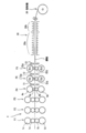
- FIG. 1 schematically illustrates an example of a suitable finishing mill in the present embodiment.
- the finishing mill 1 is a finishing rolling mill having six stages (six stands). As shown in the figure, the three stands in the first stage are provided with so-called CVC mills F1, F2 and F3.
- the mill F1 is a quadruple rolling mill composed of work rolls 1a and 1b and backup rolls 1c and 1d as shown in FIG. 1, and the work rolls 1a and 1b are relatively moved (shifted) in the axial direction. Appropriate crowns (CVCs or continuous changes in diameter) are applied to the roll surface to allow control of the shape of the steel sheet.
- CVCs or continuous changes in diameter are applied to the roll surface to allow control of the shape of the steel sheet.
- the above configuration can be similarly applied to the other two-stage CVC mills F2 and F3. By using such mills F1, F2, F3, the shape accuracy of the steel sheet obtained through the subsequent mills F4, F5, F6 can be increased.
- the different-diameter roll mill F4 which is the fourth stand counted from the mill 1, is a quadruple rolling mill composed of work rolls 4a and 4b and backup rolls 4c and 4d as shown in FIG. As shown in the figure, different diameters are used. Only the lower large-diameter roll 4b of the work rolls 4a and 4b is rotationally driven by a motor or the like (not shown), and the upper small-diameter roll 4a is rotatable so that no driving force is applied. And in addition, such a configuration can be the same for the other two-stage roll mills F5 and F6 provided at the rear. As for the rear mill, a CVC mill may be used similarly to the front mill. The stand intervals of all six stands may be equal or different.
- the roll rolls F4, F5, and F6 with three rear stands have a relatively low rolling load because the roll diameter is small and a shear force acts on the steel plate to drive only one of the work rolls (4b, etc.).
- high rolling reduction can be performed. Specifically, it is possible to realize, for example, rolling close to a draft of 50%. As a result, there is an advantage that problems such as roll flattening and edge drop do not occur because the rolling load is small.
- curtain wall type water cooling means 11, 12, and 13 may be arranged on the respective outlet sides of the three stand different-diameter roll mills F4, F5, and F6 arranged at the subsequent stage. Further, also in the run-out table 20 arranged on the downstream side of the finishing mill 1, water cooling means 20a and 20b may be arranged so that the steel sheet can be effectively cooled. In addition, it is preferable that the temperature of the steel sheet on the outlet side of the finishing mill be 800 ° C. or higher.
- the steel sheet that has been finish-rolled as described above is air-cooled for about several seconds (for example, 2 to 6 seconds), it is cooled with water and wound up.
- the main feature of the present embodiment is that the winding temperature at this time is set to 700 ° C. or higher. If the winding temperature is lower than 700 ° C., the strength of the steel sheet is increased, so that the cold rolling performed after the hot rolling disadvantageously occurs. From the above viewpoint, in the present embodiment, it is important that the winding temperature after hot rolling is set to 700 ° C. or higher.
- the upper limit of the winding temperature in the present embodiment is preferably 900 ° C. or less. The reason for setting the upper limit of the winding temperature is that if the temperature is too high, scale formation is promoted, and it takes time to remove the scale in the subsequent pickling.
- a hot-rolled steel sheet having a thickness of 1.2 mm to 3.0 mm can be obtained as an example.
- the thickness of the hot-rolled steel sheet may be less than 1.2 mm, it is necessary to keep in mind that if the thickness is less than 1.2 mm, the load applied to the rolling roll during hot rolling may be excessively increased. .
- the thickness of the hot-rolled steel sheet may exceed 3.0 mm. However, when the thickness exceeds 3.0 mm, it is noted that the load applied to the rolling rolls in the subsequent cold rolling step also increases too much. There is a need.
- the tensile strength of the hot-rolled steel sheet obtained as described above is preferably 900 MPa or less. If the tensile strength exceeds 900 MPa, the load applied to the rolling rolls during the cold rolling process performed after the hot rolling is undesirably increased.
- the hot-rolled steel sheet obtained as described above is subjected to cold rolling.
- the cold rolling is performed at a rolling reduction (reduction rate) of 60% or more in total once or a plurality of times.
- the method of cold rolling and the number of times of cold rolling are not particularly limited, and can be appropriately selected according to the target plate thickness.
- the thickness of the finally obtained cold-rolled steel sheet is not particularly limited, but is preferably, for example, in the range of 0.01 mm to 0.6 mm. It should be noted that when the thickness of the final cold-rolled steel sheet is less than 0.01 mm, the rigidity of the obtained cold-rolled steel sheet decreases. Therefore, it should be noted that the shape is easily deformed when used for products such as gaskets of gasoline engines of automobiles. On the other hand, when the thickness exceeds 0.6 mm, it is necessary to pay attention to the fact that the product may be heavier than the designed value or a required miniaturization may not be realized.
- the work-hardened steel sheet can be softened, or the distortion of the steel sheet during the cold rolled steel sheet can be removed.
- the annealing step in this embodiment may be continuous annealing or batch annealing. In the case of performing the cold rolling a plurality of times in the above-described cold rolling step, annealing can be performed each time.
- the temperature at the time of annealing is preferably 500 ° C or more. If the temperature is lower than 500 ° C., recrystallization does not occur in the steel sheet, and if the steel sheet is not softened, the rolling load in the next step increases, which is not preferable.
- the last annealing includes a soaking step and a cooling step.
- the soaking step and the cooling step (1) the main phase exceeding 50% of the structure of the steel sheet is made bainite, and further, as phases other than bainite, for example, a ferrite phase, a martensite phase, a retained austenite phase, and the like are provided.
- phases other than bainite for example, a ferrite phase, a martensite phase, a retained austenite phase, and the like are provided.
- the steel sheet structure can be in a state where the retained austenite grains are uniformly dispersed.
- a high-strength cold-rolled steel sheet having high strength and good formability can be obtained by controlling the retained austenite grains in the above-described dispersed state.
- "retained austenite grains are uniformly dispersed in the structure of the steel sheet” means that a given number of retained austenite grains of less than 10 ⁇ m are contained in an arbitrary region of the steel sheet. Define what you say. More specifically, when an arbitrary 10 ⁇ m ⁇ 10 ⁇ m region of a steel sheet is defined as a unit area, a case where one or more retained austenite grains are included per arbitrary unit area is uniformly dispersed. . At this time, it is further preferable that the ratio of the retained austenite structure to the steel sheet is not less than a certain value. More specifically, in the uniformly dispersed state, it can be said that the volume ratio of the retained austenite structure to the steel sheet is more preferably 8% or more.
- the retained austenite grains in order to achieve both high strength and excellent ductility in a high dimension, for example, several ⁇ m order exceeding 0.1 ⁇ m (a size exceeding 0.1 ⁇ m and less than 10 ⁇ m, which are particularly significant) are dispersed in the structure of the steel sheet in the above-mentioned state.
- the “size of retained austenite grains” described above means a particle size in the present embodiment. Specifically, when one residual austenite grain is included per arbitrary unit area, the longest part of the grain is defined as the grain size. Further, when a plurality of retained austenite grains are contained per arbitrary unit area, the grain size is measured for each of them in the same manner as in the case of one piece, and the average value thereof is adopted.
- the soaking temperature of the steel sheet is preferably set to the Ac1 transformation point or higher and 1000 ° C or lower, and the soaking is preferably maintained for 30 seconds or longer. If the soaking temperature is lower than the Ac1 transformation point, the steel sheet has a microstructure having ferrite as a matrix, and thus the steel sheet strength required in the present embodiment cannot be obtained. On the other hand, when the soaking temperature exceeds 1000 ° C., there is no particular advantage and there is a disadvantage in cost. Therefore, the soaking temperature is set to 1000 ° C. in the present embodiment.
- the cooling step in this embodiment is a step subsequent to the above-mentioned soaking step. After cooling the steel sheet at a cooling rate of 10 ° C./s to 100 ° C./s to a holding temperature of 350 to 500 ° C., the cooling step is performed for 60 seconds or more to 720 °. Preferably, the step is to hold for not more than seconds.
- the cooling rate is less than 10 ° C./s, the steel sheet has a microstructure mainly composed of ferrite, so that the steel sheet strength required in the present embodiment cannot be obtained.
- cooling equipment such as water cooling is required instead of gas cooling, which increases costs, which is not preferable.
- the holding time is less than 60 seconds or exceeds 720 seconds, the amount of retained austenite ( ⁇ R amount) required for the TRIP effect decreases.
- the holding temperature is lower than 350 ° C., the ratio of the martensite structure increases, and the steel sheet elongation required in the present embodiment cannot be obtained.
- the holding temperature exceeds 500 ° C., the ferrite phase of the steel sheet increases, so that the strength of the steel sheet required in the present embodiment cannot be obtained.
- the cold-rolled steel sheet obtained as described above may be subjected to temper rolling for surface roughness adjustment, electroplating of Zn, Ni, Sn or the like for rust prevention and chemical conversion treatment as necessary. Can be.
- ⁇ Laminate> The tempered rolled sheet obtained as described above, the cold-rolled steel sheet obtained by performing the electroplating and the chemical conversion treatment, if necessary, a thermoplastic resin film or a thermosetting resin on at least one side of the steel sheet.
- the film can be coated.
- thermoplastic resin used for such a film examples include (1) olefin-based resin films such as polyethylene, polypropylene, ethylene-propylene copolymer, ethylene-vinyl acetate copolymer, ethylene-acrylic ester copolymer, and ionomer; ) Polyesters such as polyethylene terephthalate, polyethylene naphthalate, polybutylene terephthalate, ethylene terephthalate / isophthalate copolymer, (3) polyamides such as nylon 6, nylon 6.6, nylon 11, nylon 12, and (4) polyvinyl chloride And polyvinylidene chloride.
- thermosetting resin examples include an epoxy resin and a vinyl ester resin.
- thermoplastic resins or thermosetting resins include, for the purpose of improving properties such as strength, inorganic fibers such as glass fiber, carbon fiber, boron fiber, silicon carbide fiber, and alumina fiber, aramid fiber, and polyparaphenylene benzobis.
- a fiber reinforcing agent such as an organic fiber such as an oxazole fiber, an aluminum fiber, an alumina fiber, a SUS fiber, a metal fiber such as a copper fiber may be mixed.
- examples of the form of the reinforcing fiber include a nonwoven fabric, a chopped fiber, a combination of a nonwoven fabric and a woven or knitted fabric, and the like.
- thermoplastic resin films or thermosetting resin films have different characteristics in terms of heat resistance, corrosion resistance, impact resistance, and adhesion to a steel plate, but can be used properly depending on the application.
- an adhesive can be used as necessary, such as an epoxy-based adhesive, a phenol-based adhesive, and an amide-based adhesive.
- the cold rolled steel sheet obtained as described above can be applied as a material for press forming.
- the cold rolled steel sheet in the present embodiment is obtained by the above-described manufacturing method.
- the composition of the cold rolled steel sheet in the present embodiment is as follows: C: 0.1 to 0.3%, Si: 1.0 to 2.0%, Mn: 1.0 to 2. 5%, Cr: 0.5% or less, Ni: 1.0% or less, P: 0.01% or less, S: 0.006% or less, N: 0.015% or less, Cu: 0.5% or less
- the balance has the composition of Fe and inevitable impurities.
- the content of each element is the same as the description of the above-mentioned rolled material, and thus the description is omitted here.
- the cold-rolled steel sheet according to the present embodiment is characterized in that, in its structure, the main phase has a bainite structure, and further, as phases other than the bainite, for example, a ferrite phase, a martensite phase, and a retained austenite phase. Further, the cold-rolled steel sheet according to the present embodiment is characterized in that retained austenite grains having a size of less than 10 ⁇ m are present in an arbitrary region of the steel sheet.
- the cold-rolled steel sheet according to the present embodiment is characterized in that the retained austenite grains are uniformly dispersed. That is, the cold-rolled steel sheet according to the present embodiment is characterized in that an arbitrary region contains a predetermined number or more of retained austenite grains having a grain size of less than 10 ⁇ m. Specifically, when an arbitrary area of 10 ⁇ m ⁇ 10 ⁇ m of the cold-rolled steel sheet of the present embodiment is defined as a unit area, one or more residual austenite grains having a particle size of less than 10 ⁇ m are included per arbitrary unit area. It is characterized by the following.
- the unit area contains one or more residual austenite grains having a particle size of 0.1 ⁇ m to less than 10 ⁇ m (more preferably, more than 1 ⁇ m to less than 10 ⁇ m, which is particularly significant). preferable. More preferably, the number is eight or more.
- the retained austenite grains having a particle size in the above-described range to the cold-rolled steel sheet, a cold-rolled steel sheet having higher strength and higher ductility can be obtained. As a result, they have found that both the formability and the strength can be achieved even when the thickness of the cold-rolled steel sheet of the present embodiment is reduced or when the cold-rolled steel sheet is formed into a small part.
- the above-mentioned particle size is measured by the EBSD method (measuring device: as an example, TSL Solutions Co., Ltd., OIM analysis, measurement range: 50 ⁇ 50 ⁇ m, measurement STEP: 0.1 ⁇ m, CI value: 0.05)
- the measurement can be performed using the “CleanUP processing: measured by GrainDilation”.
- FIG. 2 is a photograph of a cross-sectional structure of a cold-rolled steel sheet (Example 10) manufactured in the scope of the present invention according to the EBSD method.
- FIG. 3 is a photograph of a cross-sectional structure of a cold-rolled steel sheet (Comparative Example 11) manufactured outside the scope of the present invention, as measured by the EBSD method. From this figure, it is confirmed that one or more residual austenite grains having a particle size of less than 10 ⁇ m are not present per unit area of 10 ⁇ m ⁇ 10 ⁇ m.
- the ratio of the retained austenite grains in the steel sheet structure is preferably equal to or more than a certain value. That is, when a large number of retained austenite grains are present, the TRIP phenomenon occurs, and good strength and formability can be obtained.
- the volume ratio of the retained austenite structure to the steel sheet is preferably 8% or more.
- the cold-rolled steel sheet according to the present embodiment is further characterized in that the tensile strength TS is 700 MPa or more and 1400 MPa or less. Furthermore, when the breaking elongation is EL%, the following formula is satisfied. TS ⁇ 1400- (30 ⁇ EL) The above-described tensile strength and elongation at break can be measured according to JIS Z 2241.
- the cold-rolled steel sheet of the present embodiment preferably further has a work-hardening index n value, which is a value indicating work-hardening characteristics, of 0.20 or more.
- the work hardening index n value is a numerical value that is considered to be good as the bending workability increases as the value increases, and takes a value of 0 ⁇ n ⁇ 1 (Ichi Sudo: Material Testing Method, Uchida Ritsuruhosha, ( 1976), p.
- the cold-rolled steel sheet of the present embodiment preferably has a work hardening index (n value) of 0.20 or more in a direction parallel to the rolling direction.
- the cold-rolled steel sheet of the present embodiment has the above-described configuration, it has excellent formability when processed.
- the cold rolled steel sheet of the present embodiment preferably has a critical overhang height of 6.5 mm or more. That is, when the overhang test is performed based on JIS Z 2247 and measured, the height at which a crack occurs during overhang is defined as the overhang height, and the overhang height is 6.5 mm or more. Is preferred.
- the cold-rolled steel sheet of the present embodiment preferably has a critical drawing ratio of 2.0 or more. That is, the ratio (D / d) of the maximum blank diameter D obtained in the deep drawing test and drawn without breaking and the punch diameter d is defined as the limit drawing ratio (LDR). In the present embodiment, when LDR ⁇ 2.0, it is determined that the deep drawability is good.
- ⁇ r (r 0 ⁇ r 90 ) / 2 ⁇ r 45
- r 0 is a value obtained by cutting out a No. 5 test piece from the cold-rolled annealed sheet from the L direction (rolling direction) and conforming to JIS Z2254.
- r 45 and r 90 No. 5 test pieces from the cold-rolled annealed sheet in the D direction (a direction at 45 ° to the rolling direction) and the C direction (a direction at 90 ° to the rolling direction), respectively. Is a value obtained in accordance with JIS Z2254.
- Example 1 Molten steel having the components shown in Table 1 was used as a slab (rolled material) by a continuous casting method. The thickness of the slab was 230 mm. Subsequently, the slab was heated to 1250 ° C., and then roughly rolled at a rolling reduction of 80%. Thereafter, finish rolling was performed at 1050 ° C. using a six-roll mill shown in FIG. The finishing pre-rolling mills 1 to 3 were used, and the average rolling reduction per finishing pre-rolling mill was 43%. The cumulative strain under the rolling of the finishing three-stage rolling mill was 0.5. The temperature of the steel sheet on the exit side of the finishing mill was 900 ° C.
- the Rigaku RINT2000 / PC software Instructions for the residual austenite determination program According to the procedure described in the book, smoothing treatment, background removal, strength calculation, and quantitative calculation were respectively performed to determine the volume ratio of retained austenite. Table 3 shows the obtained results. In the present invention, when the volume ratio of the retained austenite grains is 8% or more, it can be determined that the phase structure is good.
- the distribution state of the retained austenite grains was measured by an EBSD (electron back scattering difference) method using a scanning electron microscope (SEM). As a measuring device, TSL Solutions OIM analysis was used. A scanning electron microscope (FE-SEM (SU8020) manufactured by Hitachi High-Technologies Corporation) was measured using the same sample as the measurement sample in the X-ray diffraction method. In Example 1, as an example, ⁇ was given when eight or more retained austenite grains having a particle size of less than 10 ⁇ m per unit area of 10 ⁇ m ⁇ 10 ⁇ m were included, and ⁇ was given when none of them was included. Further, the average value of the particle diameters of all the retained austenite grains observed per unit area was calculated. Table 3 shows the results.
- n value was calculated based on JIS Z 2253 using the results obtained by the tensile test. Table 3 shows the results of the obtained n values. In the present invention, when the n value is 0.20 or more, it can be determined that the moldability is good.
- Example 2 ⁇ Examples 2 to 21, Comparative Examples 1 to 13>
- Example 2 to 21 and Comparative Examples 1 to 13 were performed.
- the cold-rolled steel sheets to be used had the components shown in Table 1, and were subjected to the same conditions as in Example 1 except that the rolling was performed under the conditions shown in Table 3 or Table 4. The obtained results are shown in Tables 3 and 4, respectively.
- Table 2 shows the mechanical properties of the hot-rolled steel sheet after hot rolling.
- steel types 1 to 3 are slab pieces falling within the component range of the present invention, while steel types 4 to 6 are slab pieces outside the component range of the present invention. Using the slab pieces of these steel types 1 to 6, respective values of the examples and comparative examples were obtained.
- the winding temperature (CT) of steel type 4 was as low as 480 ° C
- the tensile strength (TS) was as high as 1034 MPa.
- CT winding temperature
- TS tensile strength
- the thickness could not be reduced to the target of 0.6 mm or less, and cracks occurred when the number of times of rolling and the rolling load were increased, so the cold rolling was stopped.
- the test in which the winding temperature was changed was not performed because the winding temperature was low and the steel might be hardened and cracked during cold rolling.
- the hot-rolled steel sheet and the cold-rolled steel sheet of the present invention and the method for producing them it is possible to obtain a high-strength cold-rolled steel sheet excellent in formability and a hot-rolled steel sheet as a material thereof.
- the high-strength cold-rolled steel sheet of the present invention has excellent formability without cracking even when it is formed into a small part by press forming or the like as a thin plate.
- the high-strength cold-rolled steel sheet of the present invention can realize a demand for miniaturization and weight reduction of a molded product, and has extremely high industrial applicability.
- the high-strength cold-rolled steel sheet of the present invention can be used for gaskets of gasoline engines of automobiles, housings of notebook computers and smartphones, frame parts of electronic devices, and the like.
Landscapes
- Chemical & Material Sciences (AREA)
- Engineering & Computer Science (AREA)
- Mechanical Engineering (AREA)
- Materials Engineering (AREA)
- Metallurgy (AREA)
- Organic Chemistry (AREA)
- Physics & Mathematics (AREA)
- Thermal Sciences (AREA)
- Crystallography & Structural Chemistry (AREA)
- Heat Treatment Of Sheet Steel (AREA)
- Metal Rolling (AREA)
- Heat Treatment Of Steel (AREA)
Abstract
合計で30%以上の圧下率で圧延素材を粗圧延する第1ステップと、800℃以上の温度環境下において互いに径の異なる複数の異径ロールを用いて合計で40%以上の圧下率で圧延素材を仕上げ圧延する第2ステップと、700℃以上の温度環境下において巻き取りを行う第3ステップと、をそれぞれ含む、冷間加工時の負荷が少なく、しかも成形性及び残留オーステナイトの評価に関して一定の条件を満たす成形性と延性に優れた高強度冷延鋼板及びその素材となる熱延鋼板並びにこれらの製造方法。
Description
本発明は、成形性に優れた高強度の冷延鋼板及び熱延鋼板に関し、より詳細には深絞り加工など厳しい加工に耐え得る延性を備えた高強度冷延鋼板及び優れた成形性を引出すための熱延鋼板並びにその製造方法に関する。
例えば現代の移動手段として不可欠な自動車は、強度の高い鋼板をプレス成形して製造された部品が用いられている。かような高強度鋼板を製造するにあたっては、いわゆるホットプレス法といった製造方法が用いられることがある。
ホットプレス法は、鋼板を高温環境下において軟質化させて熱間でプレス加工をするのでスプリングバックの発生量は極めて少なく、形状凍結性が良いという利点を有する。また、ホットプレスの際の焼入れ効果で、非常に高い強度をもった部品を高精度で提供できるという利点もある。
ホットプレス法は、鋼板を高温環境下において軟質化させて熱間でプレス加工をするのでスプリングバックの発生量は極めて少なく、形状凍結性が良いという利点を有する。また、ホットプレスの際の焼入れ効果で、非常に高い強度をもった部品を高精度で提供できるという利点もある。
しかしながら、上記したホットプレス法においては、プレス加工前に鋼板を高温となるように加熱することが必須であり、また、ホットプレス後にスケールを落とす作業が必要となる。従って、ホットプレス法は、上述したメリットはあるものの、一般的に作業効率が非常に悪くコスト高となってしまうといった難点も存在する。さらには、プレス成形用の金型が加熱した鋼板と接するため金型の寿命が比較的短いことも欠点として存在し、これも製造コストを増加させる一因となっている。
一方、上記した自動車用部品に加え、例えば携帯電話やノートパソコン等に用いられるディスプレイ用のフレーム部品などは、いわゆる冷間プレスを用いて冷延鋼板として成形されることも多い。かような冷間加工は、一般に720℃以下の温度環境下で加工を行う方法であり、鋼板の持つ金属組織が緻密になるといった特徴も有している。
ここで、近年における情報機器や自動車部品には軽量化や小型化の厳しい要求もあり、これらの部品を低コストで軽量化して小型化するためには冷延鋼板を薄くする必要がある。そして薄板化した鋼板においては同じ強度ではプレス部品としての強度を確保できないため、薄板かつ高強度を有する高強度鋼板を提供する必要がある。他方、強度だけを追求してしまうと延性が低下してしまい、プレス成形時などに割れが生じてしまう点にも配慮する必要がある。
このような要請に応えるべく、例えば特許文献1~4に例示されるごとき高強度高延性材(以下、「TRIP鋼」とも称する)が提案されている。
例えば特許文献1では、引張強度が1000MPa以下の熱間圧延鋼板を合計で60%以上の圧延率で冷間圧延を行って冷延鋼板とし、さらに均熱温度を750℃以上として焼鈍処理を行った上で3℃/s~100℃/sで冷却することで、引張強度が1280MPa以上で破断伸びが3%以上の高強度冷延鋼板を得られるということが開示されている。
例えば特許文献1では、引張強度が1000MPa以下の熱間圧延鋼板を合計で60%以上の圧延率で冷間圧延を行って冷延鋼板とし、さらに均熱温度を750℃以上として焼鈍処理を行った上で3℃/s~100℃/sで冷却することで、引張強度が1280MPa以上で破断伸びが3%以上の高強度冷延鋼板を得られるということが開示されている。
しかしながら上記した特許文献1~4を含む従来の技術では市場のニーズを満たしているとは言えず、以下に述べる課題が存在する。
まず特許文献1で開示される高強度冷延鋼板は、たしかに強度と延性とを両立した優れた性質を備えているが、更なる軽量化や小型化のためにはより高い延性を兼ね備えた高強度冷延鋼板が希求されることが予想される。
まず特許文献1で開示される高強度冷延鋼板は、たしかに強度と延性とを両立した優れた性質を備えているが、更なる軽量化や小型化のためにはより高い延性を兼ね備えた高強度冷延鋼板が希求されることが予想される。
また、TRIP鋼を開示する特許文献2~4に関しては、成形性に優れるとの言及はあるものの、例えば深絞り成形性といった実際の評価が殆ど実施されておらず、実施例の内容としても一部の文献で限界絞り比が記載されている程度に留まっており成形性の評価としては明らかに不十分である。加えてこれらの文献においては、TRIP鋼でキーエレメントとなる残留オーステナイトの評価に関しても、残留オーステナイト量が記載されている程度に留まっており、かようなTRIP鋼では局所的な割れ等を引き起こす可能性がある為、改善の余地が多分にある。
本発明は、かような課題を一例として解決することを鑑みてなされたものであり、冷間加工時の負荷が少なく、しかも成形性及び残留オーステナイトの評価に関して一定の条件を満たす成形性と延性に優れた高強度冷延鋼板及びその素材となる熱延鋼板並びにこれらの製造方法を提供することを目的とする。
上記課題を解決するため、本発明の一実施形態にかかる高強度冷延鋼板の素材となる熱延鋼板の製造方法は、(1)質量%での含有量として、C:0.1~0.3%、Si:1.0~2.0%、Mn:1.0~2.5%、Cr:0.5%以下、Ni:1.0%以下、P:0.01%以下、S:0.006%以下、N:0.015%以下、Cu:0.5%以下、残部がFeおよび不可避的不純物の組成となる圧延素材を、合計で30%以上の圧下率で前記圧延素材を粗圧延する第1ステップと、前記第1ステップの後、冷延・焼鈍後の残留オーステナイトの凝集や粗粒化を抑制するため800℃以上の温度環境下において互いに径の異なる複数の異径ロールを用いて合計で40%以上の圧下率で前記圧延素材を仕上げ圧延する第2ステップと、前記第2ステップの後、700℃以上の温度環境下において前記圧延素材の巻き取りを行うことで引張強度が900MPa以下で熱延鋼板を製造する第3ステップと、を含むことを特徴とする。
なお上記(1)に記載の熱延鋼板の製造方法においては、(2)前記第1ステップにおいては、1100℃以上の温度環境下において前記圧延素材に対して粗圧延を行うことが好ましい。
また、上記(1)又は(2)に記載の熱延鋼板の製造方法においては、(3)前記第2ステップにおいては、仕上げ前段における圧延機1台当りの平均圧下率が40%以上となり、且つ、仕上げ後段における圧延機による圧下の累積歪が0.5以上となるように仕上げ圧延を行うことが好ましい。
そして上記課題を解決するため、本発明の一実施形態にかかる高強度冷延鋼板の製造方法は、上記した(1)~(3)のいずれかに記載の熱延鋼板の製造法により得られた熱延鋼板を、冷間圧延して冷延鋼板を製造する第4ステップを含むことを特徴とする。
なお、上記した(4)に記載の高強度冷延鋼板の製造方法においては、(5)前記第4ステップにおいて、合計で60%以上の圧下率で前記熱延鋼板を冷間圧延することが好ましい。
また、上記した(5)に記載の高強度冷延鋼板の製造方法においては、(6)前記第4ステップの後、Ac1点以上の均熱温度で前記冷延鋼板を焼鈍した後に冷却保持する第5ステップを更に有することが好ましい。
また、上記した(4)~(6)のいずれかに記載の高強度冷延鋼板の製造方法においては、(7)前記熱延鋼板の厚みが1.2~3.0mmであり、前記冷延鋼板の厚みが0.01~0.6mmであることが好ましい。
さらに上記した課題を解決するため、本発明の一実施形態にかかる熱延鋼板は、(8)質量%での含有量として、C:0.1~0.3%、Si:1.0~2.0%、Mn:1.0~2.5%、Cr:0.5%以下、Ni:1.0%以下、P:0.01%以下、S:0.006%以下、N:0.015%以下、Cu:0.5%以下、残部がFeおよび不可避的不純物の組成を有し、厚さが1.2~3.0mmであり、引張強度が900MPa以下であることを特徴とする。
さらに上記した課題を解決するため、本発明の一実施形態にかかる高強度冷延鋼板は、(9)質量%での含有量として、C:0.1~0.3%、Si:1.0~2.0%、Mn:1.0~2.5%、Cr:0.5%以下、Ni:1.0%以下、P:0.01%以下、S:0.006%以下、N:0.015%以下、Cu:0.5%以下、残部がFeおよび不可避的不純物の組成を有し、主相をベイナイト組織とし、さらに前記ベイナイト組織以外にフェライト組織、マルテンサイト組織及び残留オーステナイト組織を含み、10μm平方の単位面積当たりに10μm未満の残留オーステナイト粒が1個以上分散され、引張り強度TSが700MPa以上1400MPa以下であり、且つ、破断伸びをEL%としたとき、TS≧1400-(30×EL)を満足することを特徴とする。
なお上記した(9)に記載の高強度冷延鋼板を得るためには、質量%での含有量として上記と同様の組成を有し、厚さが1.2~3.0mmであり、引張強度が900MPa以下である熱延鋼板を素材とすることが好ましい。
なお上記した(9)に記載の高強度冷延鋼板を得るためには、質量%での含有量として上記と同様の組成を有し、厚さが1.2~3.0mmであり、引張強度が900MPa以下である熱延鋼板を素材とすることが好ましい。
また、上記した(9)に記載の高強度冷延鋼板においては、(10)前記高強度冷延鋼板における加工硬化の特性を示すn値が0.20以上であることが好ましい。
また、上記した(9)又は(10)に記載の高強度冷延鋼板においては、(11)前記残留オーステナイト組織が占める体積割合が8%以上であることが好ましい。
また、上記した(9)~(11)のいずれかに記載の高強度冷延鋼板においては、(12)前記高強度冷延鋼板における厚みが0.01~0.6mmであることが好ましい。
また、上記した(9)~(12)のいずれかに記載の高強度冷延鋼板においては、(13)前記高強度冷延鋼板における限界張出高さが6.5mm以上であることが好ましい。
また、上記した(9)~(13)のいずれかに記載の高強度冷延鋼板においては、(14)前記高強度冷延鋼板における限界絞り比が2.0以上であることが好ましい。
また、上記した(9)~(14)のいずれかに記載の高強度冷延鋼板においては、(15)前記高強度冷延鋼板におけるΔrが±0.7の範囲であることが好ましい。
また、上記した(9)~(15)のいずれかに記載の高強度冷延鋼板においては、(16)前記高強度冷延鋼板における耳率が10%以下であることが好ましい。
本発明によれば、冷間加工時の負荷が少なく、しかも高い成形性と高い強度を高次元で両立できる優れた高強度冷延鋼板を実現できる。あるいは本発明によれば、かような優れた高強度冷延鋼板を実現するための素材となる熱延鋼板を提供することができる。
高強度でいて延性にも優れた鋼板について鋭意研究を行った結果、発明者らは、適正な成分組成、熱延条件、冷延条件、および焼鈍条件などの採用で、理想的な延性も具備した好ましい高強度鋼板が得られることを見出した。すなわち、適正な成分範囲を有するスラブを、熱間圧延における粗圧延で高圧下圧延を施し、さらに仕上げ圧延での後段高ひずみ圧延を高温で終了し、そして所定時間(例えば数秒)の空冷をした後に冷却を開始し、その後に適正な温度環境下で冷却した鋼板を巻き取ることで、冷間加工しやすく組織の均一性に優れた熱延鋼板を得ることが出来るといった知見を得た。さらにこの熱延鋼板に対して適切な冷間圧延を施し、そして適切な条件で最終焼鈍を行うことで、成形性に優れた高強度冷延鋼板を製造することができることが判明した。
以下、上記知見を具現化した本実施形態における鋼板などの詳細を説明する。
以下、上記知見を具現化した本実施形態における鋼板などの詳細を説明する。
<圧延素材>
本実施形態の高強度冷延鋼板及びその素材となる熱延鋼板の製造方法に用いられる圧延素材としては、特定の組成を有するスラブ片を使用することができる。前記組成としては、質量%での含有量として、C:0.1~0.3%、Si:1.0~2.0%、Mn:1.0~2.5%、Cr:0.5%以下、Ni:1.0%以下、P:0.01%以下、S:0.006%以下、N:0.015%以下、Cu:0.5%以下、残部がFeおよび不可避的不純物、とすることができる。
本実施形態の高強度冷延鋼板及びその素材となる熱延鋼板の製造方法に用いられる圧延素材としては、特定の組成を有するスラブ片を使用することができる。前記組成としては、質量%での含有量として、C:0.1~0.3%、Si:1.0~2.0%、Mn:1.0~2.5%、Cr:0.5%以下、Ni:1.0%以下、P:0.01%以下、S:0.006%以下、N:0.015%以下、Cu:0.5%以下、残部がFeおよび不可避的不純物、とすることができる。
C(炭素)は、本実施形態における特徴である残留オーステナイト組織を安定化させるために重要な元素である。C量としては、上述したように0.1~0.3%の含有量が必要である。C量が0.1%未満である場合、必要とされる残留オーステナイト組織の安定度を得ることができない。一方で、C量が0.3%を超える場合、例えば鋼板を溶接した場合に溶接部が硬化しすぎて溶接部から破断しやすくなる、等の問題があるため、好ましくない。
Si(シリコン)も、残留オーステナイト組織を安定化させるために重要な元素である。Si量としては、上述したように1.0~2.0%の含有量が必要である。また、Siは固溶強化による鋼板の強度の向上にも寄与する元素である。Si量が増加するほど鋼板の残留オーステナイト組織の安定性及びその体積割合が増加するが、本実施形態においてSi量を上記のように規定した理由は以下のとおりである。すなわち、Si量が1.0%未満の場合、本実施形態に必要とされる鋼板の複合組織と材料特性を得ることができない。一方で、Si量が2.0%を超えた場合には、本実施形態に必要とされる鋼板の強度と延性の好ましいバランスが得られない。また、コスト低減の観点から、本実施形態においてはSi量の上限を2.0%とした。
Mn(マンガン)は鋼板強度を高くするために必要とされる元素である。Mn量としては、上述のように1.0~2.5%であることが必要である。Mn量が1.0未満の場合、フェライト量が増加し、高い鋼板強度を得ることができない。一方で、Mn量が2.5%を超えた場合、マルテンサイトが生成しやすくなり、本実施形態において必要とされる複合組織を得ることができない。そのため、本実施形態においては上述のMn量を規定することとした。
Cr(クロム)量は上述のように0.5%以下であることが必要である。Cr量が0.5%を超える場合にはAc1変態点が上昇し、Ac1変態点以上での焼鈍を行う際にコスト上昇につながるという問題があるためである。そのため、本実施形態においては上述のCr量を規定することとした。
Ni(ニッケル)量は上述のように1.0%以下であることが必要である。Niの添加により鋼板の強度を向上させることができる。Ni量が1.0%を超える場合にはマルテンサイトが生成しやすくなり、本実施形態において必要とされる複合組織を得ることができない。また、コストの観点から、本実施形態においてはNiを上述のように規定した。
P(リン)は、鋼板の溶接性向上のためにできるだけ少なくすることが必要である。従って、本実施形態においてはP量を0.01%以下とする。
S(硫黄)も、鋼板の溶接性向上のためにできるだけ少なくすることが必要である。従って、本実施形態においてはS量を0.006%以下とする。
N(窒素)は、炭素と同様にオーステナイト組織の安定化に必要な元素である。一方で本実施形態においてN量を0.015%以下とした理由としては、0.015%を超えた場合には鋼板の溶接性を低下させるためである。
Cu(銅)は、固溶強化もしくは析出強化によって強度を向上させるために必要な元素であることから一定量を添加することができる。一方で本実施形態においてCu量を0.5%以下とした理由としては、熱間圧延時の脆化を引き起こす恐れがあるためである。
本実施形態の圧延素材の組成としては、残部は、Feおよび不可避的不純物である。不可避的不純物とは、意図的に添加しなくても含まれてしまう成分を指す。かような不可避的不純物の具体例としては、Zn:0.03%以下、Sn:0.3%以下、等が挙げられる。
<高強度冷延鋼板及びその素材となる熱延鋼板の製造方法>
本実施形態における高強度冷延鋼板の製造方法は、下記に述べる熱間圧延の工程と、さらに冷間圧延の工程と、を有する。また特に本実施形態の高強度冷延鋼板及びその素材となる熱延鋼板の製造方法は、前記熱間圧延の工程において、上記組成からなる圧延素材を合計で30%以上の圧下率で前記圧延素材を粗圧延する第1ステップと、前記第1ステップの後、冷延・焼鈍後の残留オーステナイトの凝集や粗粒化を抑制するため800℃以上の温度環境下において互いに径の異なる複数の異径ロールを用いて合計で40%以上の圧下率で前記圧延素材を仕上げ圧延する第2ステップと、前記第2ステップの後、700℃以上の温度環境下において前記圧延素材の巻き取りを行うことで引張強度が900MPa以下の熱延鋼板を製造する第3ステップと、を含むことを特徴とする。
以下、この高強度冷延鋼板及びその素材となる熱延鋼板の製造方法について詳細に説明する。
本実施形態における高強度冷延鋼板の製造方法は、下記に述べる熱間圧延の工程と、さらに冷間圧延の工程と、を有する。また特に本実施形態の高強度冷延鋼板及びその素材となる熱延鋼板の製造方法は、前記熱間圧延の工程において、上記組成からなる圧延素材を合計で30%以上の圧下率で前記圧延素材を粗圧延する第1ステップと、前記第1ステップの後、冷延・焼鈍後の残留オーステナイトの凝集や粗粒化を抑制するため800℃以上の温度環境下において互いに径の異なる複数の異径ロールを用いて合計で40%以上の圧下率で前記圧延素材を仕上げ圧延する第2ステップと、前記第2ステップの後、700℃以上の温度環境下において前記圧延素材の巻き取りを行うことで引張強度が900MPa以下の熱延鋼板を製造する第3ステップと、を含むことを特徴とする。
以下、この高強度冷延鋼板及びその素材となる熱延鋼板の製造方法について詳細に説明する。
<製鋼>
まず、公知の方法により上記した成分範囲に調整したスラブ(圧延素材)を準備する。スラブの準備には、転炉や電気炉等の公知の設備を使用することができる。
まず、公知の方法により上記した成分範囲に調整したスラブ(圧延素材)を準備する。スラブの準備には、転炉や電気炉等の公知の設備を使用することができる。
<熱間圧延>
本実施形態における熱間圧延の工程は、後述するように、粗圧延の工程、仕上げ圧延の工程、及び巻き取りの工程を含む。
本実施形態における熱間圧延の工程は、後述するように、粗圧延の工程、仕上げ圧延の工程、及び巻き取りの工程を含む。
得られた圧延素材を、まず1100℃以上に加熱した後、合計で30%以上の圧下率で粗圧延する(第1ステップ)。圧延素材の加熱温度が1100℃未満の場合、Nの積極的分解固溶が不足すること、及び、熱延負荷が高くなることから好ましくない。
前記第1ステップの後、800℃以上の温度環境下において互いに径の異なる複数の異径ロールを用いて、合計で40%以上の圧下率で、前記圧延素材を仕上げ圧延する(第2ステップ)。具体的には、例えば6台圧延機や7台圧延機を用いて仕上げ圧延を行うことが好ましい。
この際、仕上げ前段圧延機1~3圧延機(6台圧延機の場合)、或いは仕上げ前段圧延機1~4圧延機(7台圧延機の場合)を用い、仕上げ前段圧延機一台当たりの平均圧下率40%以上で圧延を行うことができる。またその際、仕上げ後段3圧延機の圧下の累積歪は0.5以上であることが好ましい。上記累積歪が0.5未満である場合、残留オーステナイトの凝集ならびに粒が大きくなり、且つ前記残留オーステナイト粒の形が圧延された扁平となり、異方性の大きな原因となるため好ましくないからである。
なお、上記「累積歪み」とは、後段3スタンドの各段(各パス)での歪みを金属組織に対する影響の強さを考慮して加重積算したもので、最終段(最終パス)とその前段(前パス)・前々段(前々パス)での歪みをそれぞれεn、εn-1、εn-2とするとき、
εC=εn+εn-1/2+εn-2/4
で表されるεCをいうものとする。
また、歪みεとは、各スタンド(各段、または粗圧延時の各パス)の入側での鋼板の厚さh0と出側での厚さh1の差を両者の平均厚さで除した
ε=(h0-h1)/{(h0+h1)/2}
で表すことができる。
εC=εn+εn-1/2+εn-2/4
で表されるεCをいうものとする。
また、歪みεとは、各スタンド(各段、または粗圧延時の各パス)の入側での鋼板の厚さh0と出側での厚さh1の差を両者の平均厚さで除した
ε=(h0-h1)/{(h0+h1)/2}
で表すことができる。
仕上げ圧延の際には、前記圧延素材の最トップ部の圧延機への噛み込みより5m以内は、鋼板の圧延ロールへの噛み込み不良を抑制する必要がある。そのため、前記圧延素材の最トップ部を、必要に応じ、前段圧延機1~5圧延機(仕上げ圧延機6段の場合)あるいは前段圧延機1~6圧延機(仕上げ圧延機7段の場合)に、その圧延機の予定圧下量(所定の圧延のための本来の圧下量)の10%以下の圧下量を付加して圧下することが好ましい。
さらには、圧延中の圧延素材と圧延ロールとのスリップ発生防止の為、仕上げ最終圧延機より1~3圧延機の作業ロールとしては、特殊ハイグリップロールを使用することが好ましい。なお前記特殊ハイグリップロールに関しては、特許5214905号公報に開示されているロール等を適宜使用することができる。
次に、上記した異径ロールについて説明する。本実施形態に用いられる異径ロールは、例えば特開2007-331017号公報に開示されるような公知の異径ロールを使用することが可能である。すなわち異径ロールとは、上下一対のワークロールについて直径が等しくなく、各一対のワークロールの平均ロール径が直径で600mm未満のものをいう。このような異径ロールはワークロール径が小さいために、低い圧延荷重で高圧下の圧延を行うことができる。
図1に、本実施形態において好適な仕上げ圧延機の例について模式的に図示する。
仕上げ圧延機1は、6段(6スタンド)の仕上げ圧延機である。図のとおりミルF1~F6で構成され、まず前段の3スタンドには、いわゆるCVCミルF1・F2・F3を設けている。ミルF1は、図1のようにワークロール1a・1bとバックアップロール1c・1dとからなる4重の圧延機とし、ワークロール1a・1bには、軸長方向へ相対移動(シフト)させることによって鋼板の形状制御を可能にする適切なクラウン(CVCすなわち直径の連続的変化)をロール表面に付与している。以上の構成は、他の2段のCVCミルF2・F3でも同様とすることができる。こうしたミルF1・F2・F3を使用することにより、後段のミルF4・F5・F6を経て得られる鋼板の形状精度を高くすることができる。
仕上げ圧延機1は、6段(6スタンド)の仕上げ圧延機である。図のとおりミルF1~F6で構成され、まず前段の3スタンドには、いわゆるCVCミルF1・F2・F3を設けている。ミルF1は、図1のようにワークロール1a・1bとバックアップロール1c・1dとからなる4重の圧延機とし、ワークロール1a・1bには、軸長方向へ相対移動(シフト)させることによって鋼板の形状制御を可能にする適切なクラウン(CVCすなわち直径の連続的変化)をロール表面に付与している。以上の構成は、他の2段のCVCミルF2・F3でも同様とすることができる。こうしたミルF1・F2・F3を使用することにより、後段のミルF4・F5・F6を経て得られる鋼板の形状精度を高くすることができる。
続く後段の3スタンドとしては、いわゆる異径ロールミルF4・F5・F6を配置している。ミル1から数えて第4番目のスタンドである異径ロールミルF4は、図1のようにワークロール4a・4bとバックアップロール4c・4dとからなる4重の圧延機とし、ワークロール4a・4bとして図のように互いに直径の異なるものを使用している。そしてワークロール4a・4bのうち下部にある大径のロール4bのみをモータ等(図示せず)にて回転駆動し、上部の小径のロール4aについては、回転自在にして駆動力をかけないこととする。また、こうした構成は、後方に設けた他の2段の異径ロールミルF5・F6も同じとすることができる。後方のミルに関しても、前方のミルと同じくCVCミルとしてもよい。全6スタンドのスタンド間隔は、各々等しくしても良いし、異なっていてもよい。
これら後方3スタンドの異径ロールミルF4・F5・F6は、ロール径が細いことと、一方のワークロール(4b等)のみを駆動するため鋼板に剪断力が作用することから、比較的低い圧延荷重でも圧下率の高い圧延を実施できる。具体的には、例えば圧下率50%に近い圧延を実現できる。その結果として、圧延荷重が小さいために、ロール偏平やエッジドロップ等の問題が発生しない、というメリットがある。
後段に配置した3スタンドの異径ロールミルF4・F5・F6の各出側には、カーテンウォール型の水冷手段11・12・13を配置してもよい。また、仕上げ圧延機1の下流側に配置したランアウトテーブル20においても、鋼板を効果的に冷却できるよう水冷手段20aおよび20bを配置してもよい。
なお、仕上げ圧延機の出口側の鋼板の温度は、800℃以上となるようにすることが好ましい。
なお、仕上げ圧延機の出口側の鋼板の温度は、800℃以上となるようにすることが好ましい。
上記のように仕上げ圧延をした鋼板を、数秒程度(例えば2秒~6秒)の間空冷をしたのち、水冷冷却し、巻き取りを行う。本実施形態においては、この際の巻き取り温度を700℃以上に設定していることが主な特徴となっている。この巻き取り温度が700℃未満である場合、鋼板の高強度化を引き起こすため、熱間圧延に次いで行う冷間圧延に不都合が生じることから好ましくない。以上の観点から、本実施形態においては熱間圧延後の巻き取り温度を700℃以上とすることが重要である。一方で本実施形態における巻き取り温度の上限としては、900℃以下となることが好ましい。このような巻き取り温度の上限を規定する理由としては、温度を上げすぎるとスケール生成が促進されてしまい、その後の酸洗での脱スケールに時間を要してしまうためである。
以上に述べた熱間圧延の工程により、一例として厚さ1.2mm~3.0mmの熱延鋼板を得ることができる。この熱延鋼板の厚さが1.2mm未満でもよいが、厚さが1.2mm未満の場合には熱間圧延時の圧延ロールにかかる負荷が増えすぎることがある点に留意する必要がある。なお、熱延鋼板の厚みは3.0mmを超えてもよいが、3.0mmを超える場合にはその後に続く冷間圧延の工程においてやはり圧延ロールにかかる負荷が増えすぎてしまう点に留意する必要がある。
また、上記のようにして得られた熱延鋼板の引張強度は、900MPa以下であることが好ましい。引張強度が900MPaを超えると、熱間圧延に引き続いて行われる冷間圧延の工程の際に、圧延ロールにかかる負荷が増大するため好ましくない。
<酸洗>
得られた熱延鋼板は、熱間圧延工程において生成した表面のスケールを除去するため、公知の方法により酸洗される。
得られた熱延鋼板は、熱間圧延工程において生成した表面のスケールを除去するため、公知の方法により酸洗される。
<冷間圧延>
次いで、上記のようにして得られた熱延鋼板に対して冷間圧延が施される。本実施形態における冷延鋼板の工程では、1回又は複数回に分けて合計60%以上の圧延率(圧下率)で冷間圧延が施されることが好ましい。また、本実施形態において、冷間圧延の方法や冷間圧延の回数は、特に制限されるものではなく、目的とする板厚に応じて適宜選択することができる。
次いで、上記のようにして得られた熱延鋼板に対して冷間圧延が施される。本実施形態における冷延鋼板の工程では、1回又は複数回に分けて合計60%以上の圧延率(圧下率)で冷間圧延が施されることが好ましい。また、本実施形態において、冷間圧延の方法や冷間圧延の回数は、特に制限されるものではなく、目的とする板厚に応じて適宜選択することができる。
最終的に得られる冷延鋼板の厚みとしては、特に厳密に制限されるものではないが、例えば0.01mm~0.6mmの範囲であることが好ましい。なお、最終的な冷延鋼板の厚みが0.01mm未満の場合には、得られた冷延鋼板の剛性が小さくなる点に留意する必要はある。そのため、自動車のガソリンエンジンのガスケット等の製品に用いたときに、形状が変形しやすくなるという点も留意する。一方で、上記厚みが0.6mmを超える場合には、製品にしたときに設計値よりも重量が大きい、あるいは、要求される小型化が実現できない場合がある点には留意が必要である。
<焼鈍>
上記した冷延鋼板の工程に次いで、焼鈍を行うことによって、加工硬化した鋼板を軟質化させ、あるいは、冷延鋼板時における鋼板の歪みを除去することができる。本実施形態における焼鈍の工程は、連続焼鈍でもバッチ焼鈍であってもよい。また、上記した冷間圧延の工程において、複数回の冷間圧延を行う場合には、その都度焼鈍を行うことができる。
上記した冷延鋼板の工程に次いで、焼鈍を行うことによって、加工硬化した鋼板を軟質化させ、あるいは、冷延鋼板時における鋼板の歪みを除去することができる。本実施形態における焼鈍の工程は、連続焼鈍でもバッチ焼鈍であってもよい。また、上記した冷間圧延の工程において、複数回の冷間圧延を行う場合には、その都度焼鈍を行うことができる。
焼鈍の際の温度としては、500℃以上であることが好ましい。500℃未満の場合、鋼板中で再結晶がおこらず、軟質化しない場合には次工程の圧延負荷が増大するため好ましくないからである。
なお、本実施形態においては、最後の焼鈍において、均熱ステップ及び冷却ステップを有することが好ましい。この均熱ステップ及び冷却ステップにより、(1)鋼板の組織のうち50%の割合を超える主相をベイナイトとし、さらにベイナイト以外の相として、例えばフェライト相、マルテンサイト相、残留オーステナイト相などを有するとともに、(2)鋼板の任意の領域中に10μm未満の残留オーステナイト粒を有する状態とすることが可能となる。
さらに、上記した均熱ステップ及び冷却ステップにより、前記鋼板組織中には、前記残留オーステナイト粒が均一に分散している状態とすることができる。そして本実施形態においては、残留オーステナイト粒を上記のような分散状態に制御することにより、高い強度と良好な成形性を有する高強度冷延鋼板を得ることができるものである。
なお、本実施形態において「残留オーステナイト粒が鋼板組織中に均一に分散している」とは、鋼板の任意の領域中に、10μm未満の残留オーステナイト粒が一定の個数以上含まれていることを言うものと定義する。より具体的には、鋼板の任意の10μm×10μmの領域を単位面積とした場合、任意の単位面積当たり、残留オーステナイト粒が1個以上含まれている場合を均一に分散しているものとしている。
このとき、さらに残留オーステナイト組織の鋼板に占める割合が一定以上であることがさらに好ましい。より具体的には、上記均一に分散した状態において、残留オーステナイト組織の鋼板に占める体積割合が8%以上であることがさらに好ましいと言える。
このとき、さらに残留オーステナイト組織の鋼板に占める割合が一定以上であることがさらに好ましい。より具体的には、上記均一に分散した状態において、残留オーステナイト組織の鋼板に占める体積割合が8%以上であることがさらに好ましいと言える。
このように本実施形態では、高い強度と優れた延性を高次元で両立させるためには、例えば0.1μmを超えた数μmオーダー(0.1μmを超えて10μm未満の大きさであり、より好ましくは特に影響が大きい1μm超~10μm未満の大きさ)の残留オーステナイト粒が鋼板組織中に上記した状態で分散していることが重要である点に帰結した。
なお、上記した「残留オーステナイト粒の大きさ」は、本実施形態においては粒径を意味するものとする。具体的には、任意の単位面積当たり残留オーステナイト粒が1個含まれていた場合にはその粒の最も長い部分を粒径とする。また、任意の単位面積当たり残留オーステナイト粒が複数個含まれていた場合には、それら各々について上記1個の場合に準じて粒径を測定し、それらの平均値を採用するものとする。
なお、上記した「残留オーステナイト粒の大きさ」は、本実施形態においては粒径を意味するものとする。具体的には、任意の単位面積当たり残留オーステナイト粒が1個含まれていた場合にはその粒の最も長い部分を粒径とする。また、任意の単位面積当たり残留オーステナイト粒が複数個含まれていた場合には、それら各々について上記1個の場合に準じて粒径を測定し、それらの平均値を採用するものとする。
まず上記した均熱ステップについて詳細に説明する。本実施形態における均熱ステップにおいては、鋼板の均熱温度をAc1変態点以上1000℃以下として、30秒以上均熱保持をすることが好ましい。上記均熱温度がAc1変態点未満である場合、鋼板はフェライトを母相とする組織形態になるため、本実施形態において要求される鋼板の強度を得ることができない。一方で上記均熱温度が1000℃を超えた場合には特にメリットはなく、コスト的にデメリットとなるため、本実施形態では均熱温度を1000℃と規定した。
次いで上記した冷却ステップについて説明する。本実施形態における冷却ステップは、上述の均熱ステップに次ぐステップであり、上記鋼板を冷却速度10℃/s~100℃/sで保持温度350~500℃まで冷却した後、60秒以上~720秒以下保持するステップであることが好ましい。前記冷却速度が10℃/s未満である場合、鋼板はフェライトを主相とする組織形態になるため、本実施形態において要求される鋼板の強度を得ることができない。一方で上記した冷却速度が100℃/sを超えた場合、ガス冷却でなく水冷などの冷却設備等が必要になりコスト増となるため好ましくない。また、前記保持時間が60秒を下回ったり、720秒を超えたりすると、TRIP効果に必要な残留オーステナイト量(γR量)が低下してしまうためである。
また、前記保持温度が350℃未満である場合、マルテンサイト組織の割合が増加し、本実施形態において要求される鋼板の伸びを得ることができない。一方で前記保持温度が500℃を超えた場合、鋼板のフェライト相が増加するため、本実施形態で要求される鋼板の強度を得ることができない。
<調質圧延等>
上記のようにして得られた冷延鋼板は、必要に応じて、表面粗度調節のための調質圧延や、防錆のためのZn、Ni、Sn等の電気めっき及び化成処理を行うことができる。
上記のようにして得られた冷延鋼板は、必要に応じて、表面粗度調節のための調質圧延や、防錆のためのZn、Ni、Sn等の電気めっき及び化成処理を行うことができる。
<ラミネート>
上記のようにして得られた調質圧延板、電気めっき及び化成処理を施して得られた冷延鋼板は、必要に応じて、この鋼板の少なくとも片面側に熱可塑性樹脂フィルム又は熱硬化性樹脂フィルムを被覆することができる。
上記のようにして得られた調質圧延板、電気めっき及び化成処理を施して得られた冷延鋼板は、必要に応じて、この鋼板の少なくとも片面側に熱可塑性樹脂フィルム又は熱硬化性樹脂フィルムを被覆することができる。
かようなフィルムに用いる熱可塑性樹脂としては(1)ポリエチレン、ポリプロピレン、エチレンープロピレン共重合体、エチレンー酢酸ビニル共重合体、エチレンーアクリルエステル共重合体、アイオノマー等のオレフィン系樹脂フィルム、(2)ポリエチレンテレフタレート、ポリエチレンナフタレート、ポリブチレンテレフタレート、エチレンテレフタレート/イソフタレート共重合体等のポリエステル、(3)ナイロン6、ナイロン6・6、ナイロン11、ナイロン12等のポリアミド、(4)ポリ塩化ビニル、ポリ塩化ビニリデン等をあげることができる。
また熱硬化性樹脂としては、エポキシ樹脂、ビニルエステル樹脂等をあげることができる。
また熱硬化性樹脂としては、エポキシ樹脂、ビニルエステル樹脂等をあげることができる。
これらの熱可塑性樹脂又は熱硬化性樹脂には、強度等の特性改善を目的に、ガラス繊維、炭素繊維、ボロン繊維、炭化ケイ素繊維、アルミナ繊維等の無機繊維、アラミド繊維、ポリパラフェニレンベンゾビスオキサゾール繊維等の有機繊維、アルミ繊維、アルミナ繊維、SUS繊維、銅繊維等の金属繊維のような繊維強化剤を混入させてもよい。強化繊維の形態としては、不織布、チョップド繊維、不織布と織物または編物の組合せ等が挙げられる。また、上記繊維強化剤の他にも、染料、難燃剤、抗菌剤、酸化防止剤、可塑剤、滑剤等の公知の添加剤を混入させても良い。
これらの熱可塑性樹脂フィルム又は熱硬化性樹脂フィルムは、耐熱性、耐食性、耐衝撃性、鋼板との接着性の点において、それぞれ、異なる特徴を有するが、用途に応じて使い分けることができる。
これらの熱可塑性樹脂フィルム又は熱硬化性樹脂フィルムは、耐熱性、耐食性、耐衝撃性、鋼板との接着性の点において、それぞれ、異なる特徴を有するが、用途に応じて使い分けることができる。
また、これらの熱可塑性樹脂フィルム又は熱硬化性樹脂フィルムで鋼板を被覆する場合には、必要に応じて接着剤を用いることができ、例えば、エポキシ系接着剤、フェノール系接着剤、アミド系接着剤、ウレタン系接着剤、酸変性オレフィン樹脂系接着剤、コポリアミド系接着剤、コポリエステル系接着剤、これらのブレンド物などを介在させることもできる。
<プレス成形>
上記のようにして得られた冷延鋼板は、プレス成形用の素材として適用できる。
上記のようにして得られた冷延鋼板は、プレス成形用の素材として適用できる。
<冷延鋼板>
次に、本実施形態における冷延鋼板について詳細に説明する。本実施形態の冷延鋼板は、上記に述べた製造方法により得られるものである。
本実施形態における冷延鋼板の組成としては、質量%での含有量として、C:0.1~0.3%、Si:1.0~2.0%、Mn:1.0~2.5%、Cr:0.5%以下、Ni:1.0%以下、P:0.01%以下、S:0.006%以下、N:0.015%以下、Cu:0.5%以下、残部がFeおよび不可避的不純物の組成を有するものである。各元素の含有量については、上記圧延素材での説明と同一であるため、ここでは説明を省略する。
次に、本実施形態における冷延鋼板について詳細に説明する。本実施形態の冷延鋼板は、上記に述べた製造方法により得られるものである。
本実施形態における冷延鋼板の組成としては、質量%での含有量として、C:0.1~0.3%、Si:1.0~2.0%、Mn:1.0~2.5%、Cr:0.5%以下、Ni:1.0%以下、P:0.01%以下、S:0.006%以下、N:0.015%以下、Cu:0.5%以下、残部がFeおよび不可避的不純物の組成を有するものである。各元素の含有量については、上記圧延素材での説明と同一であるため、ここでは説明を省略する。
本実施形態における冷延鋼板は、その組織中において、主相をベイナイト組織とし、さらに前記ベイナイト以外の相として、例えばフェライト相、マルテンサイト相、残留オーステナイト相を有することを特徴としている。さらに本実施形態における冷延鋼板は、鋼板の任意の領域中に10μm未満の残留オーステナイト粒が存在することを特徴とする。
さらに本実施形態における冷延鋼板は、前記残留オーステナイト粒が均一に分散していることを特徴とする。すなわち、本実施形態の冷延鋼板においては、任意の領域中に、粒径10μm未満の残留オーステナイト粒が一定の個数以上含まれていることを特徴とする。具体的には、本実施形態の冷延鋼板の任意の10μm×10μmの領域を単位面積とした場合、任意の単位面積当たり、粒径10μm未満の大きさの残留オーステナイト粒が1個以上含まれることを特徴とする。
本実施形態において、より好ましくは、上記単位面積に粒径0.1μm~10μm未満(さらに好ましくは特に影響の大きい1μm超~10μm未満)の大きさの残留オーステナイト粒が1個以上含まれることが好ましい。より好ましくは8個以上である。このように、上記した範囲の粒径を有する残留オーステナイト粒が冷延鋼板に分布していることにより、より高強度及び高延性の冷延鋼板を得ることができる。その結果として、本実施形態の冷延鋼板の厚みをより薄くした場合や、小型部品に成形した際にも、成形性及び強度を両立させることができることを見出したものである。
なお本実施形態においては、上記した粒径は、EBSD法(測定装置:一例として、(株)TSLソリューションズ OIM analysisを用い、測定範囲50×50μm、測定STEP:0.1μm CI値:0.05以上 CleanUP処理:GrainDilationにて測定)を用いて測定することができる。図2は、本発明の本発明の範囲において製造した冷延鋼板(実施例10)のEBSD法による断面組織写真である。本例においては残留オーステナイトが白色で示されており、10μm×10μmの単位面積当たり、粒径10μm未満の大きさの残留オーステナイト粒が1個以上含まれていることが示されている(図2右側参照)。図3は本発明の範囲外で製造した冷延鋼板(比較例11)のEBSD法による断面組織写真である。同図から、10μm×10μmの単位面積当たり、粒径10μm未満の大きさの残留オーステナイト粒が1個以上存在していないことが確認される。
さらに、本実施形態の冷延鋼板においては、前記残留オーステナイト粒の鋼板組織に占める割合が一定以上であることが好ましい。すなわち、残留オーステナイト粒が多く存在する場合に、TRIP現象が発現し、良好な強度及び成形性を得ることができる。本実施形態においては、残留オーステナイト組織の鋼板に占める体積割合が8%以上であることが好ましい。このような組成とすることにより、目的とする鋼板強度と延性を高次元で両立させた冷延鋼板を得ることが可能となる。
本実施形態の冷延鋼板はさらに、引張り強度TSが700MPa以上1400MPa以下であることを特徴とする。さらには、破断伸びをEL%としたとき、以下の式を満足することを特徴とする。
TS≧1400-(30×EL)
なお、上記した引張り強度及び破断伸びは、JIS Z 2241に準拠して測定することが可能である。
TS≧1400-(30×EL)
なお、上記した引張り強度及び破断伸びは、JIS Z 2241に準拠して測定することが可能である。
また、本実施形態の冷延鋼板はさらに、加工硬化の特性を示す値である加工硬化指数n値が0.20以上であることが好ましい。なお、この加工硬化指数n値は、大きいほど曲げ加工性が良好になるとされる数値であり、0≦n≦1の値をとる(須藤一著:材料試験法、内田老鶴圃社、(1976)、p.34)。本実施形態の冷延鋼板においては、優れた強度及び延性、成形性等を実現するため、特に圧延方向に平行な方向における加工硬化指数(n値)が0.20以上であることが好ましい。
本実施形態の冷延鋼板はさらに、上記のような構成を有するため、加工した際には優れた成形性を有する。具体的には、本実施形態の冷延鋼板は、限界張出高さが6.5mm以上であることが好ましい。すなわち、JIS Z 2247に基づいて張出試験を行って測定した際に、張出時に割れが生じた際の高さを限界張出高さとし、限界張出高さが6.5mm以上であることが好ましい。
本実施形態の冷延鋼板はさらに、限界絞り比が2.0以上であることが好ましい。すなわち、深絞り成形試験において得られる、破断せずに絞り抜けた最大ブランク直径Dと、ポンチ径dの比(D/d)を限界絞り比(LDR)とする。本実施形態においては、LDR≧2.0の場合を深絞り性が良好と判断する。
本実施形態の冷延鋼板はさらに、下記で表されるΔrの値が±0.7の範囲であることが好ましい。Δrの値が大きいと成形時に不要な耳が発生してしまうため、出来るだけ小さい値をとることが好ましい。
Δr=(r0-r90)/2-r45
ここで、r0は冷延焼鈍板からL方向(圧延方向)から5号試験片を切り出し、JIS Z2254の規定に準拠して求められる値である。また、r45、r90、についても同様に、冷延焼鈍板からD方向(圧延方向と45°をなす方向)及びC方向(圧延方向と90°をなす方向)からそれぞれの5号試験片を切り出し、JIS Z2254の規定に準拠して求められる値である。
Δr=(r0-r90)/2-r45
ここで、r0は冷延焼鈍板からL方向(圧延方向)から5号試験片を切り出し、JIS Z2254の規定に準拠して求められる値である。また、r45、r90、についても同様に、冷延焼鈍板からD方向(圧延方向と45°をなす方向)及びC方向(圧延方向と90°をなす方向)からそれぞれの5号試験片を切り出し、JIS Z2254の規定に準拠して求められる値である。
本実施形態の冷延鋼板はさらに、深絞り成形後の耳率が10%以下であることが好ましい。すなわち、深絞り成形試験において円筒絞り試験を行い、成形後の耳の高さを測定し、次式で表される耳率を測定する。
耳率=Δh(hMax-hMin)/hAve×100
hMax:最大耳高さ、hMin:最少耳高さ、hAve:平均耳高さ
耳率は値が低いほど平坦な耳であり、成形性が良好と判断できる。本実施形態においては耳率が10%以下であることが好ましい。
耳率=Δh(hMax-hMin)/hAve×100
hMax:最大耳高さ、hMin:最少耳高さ、hAve:平均耳高さ
耳率は値が低いほど平坦な耳であり、成形性が良好と判断できる。本実施形態においては耳率が10%以下であることが好ましい。
<実施例>
以下に実施例を挙げて本発明について具体的に説明するが、本発明はこれら実施例に限定されるものではない。
以下に実施例を挙げて本発明について具体的に説明するが、本発明はこれら実施例に限定されるものではない。
<実施例1>
表1に示す成分を有する溶鋼を、連続鋳造法によりスラブ(圧延素材)とした。スラブの厚さは230mmとした。続いてこのスラブを1250℃に加熱した後、80%の圧下率で粗圧延した。その後、図1に示す6台圧延機を用いて1050℃において仕上げ圧延を行った。仕上げ前段圧延機1~3圧延機を用い、仕上げ前段圧延機一台当たりの平均圧下率を43%とした。仕上げ後段3圧延機の圧下の累積歪は0.5とした。仕上げ圧延機の出口側の鋼板の温度は900℃とした。
表1に示す成分を有する溶鋼を、連続鋳造法によりスラブ(圧延素材)とした。スラブの厚さは230mmとした。続いてこのスラブを1250℃に加熱した後、80%の圧下率で粗圧延した。その後、図1に示す6台圧延機を用いて1050℃において仕上げ圧延を行った。仕上げ前段圧延機1~3圧延機を用い、仕上げ前段圧延機一台当たりの平均圧下率を43%とした。仕上げ後段3圧延機の圧下の累積歪は0.5とした。仕上げ圧延機の出口側の鋼板の温度は900℃とした。
上記のように仕上げ圧延をした鋼板を3秒間空冷した後、水冷冷却し、750℃で巻き取りを行った。このようにして厚さ1.8mmの熱延鋼板を得た。得られた熱延鋼板の引張強度は700MPaであった。
上記のようにして得られた熱延鋼板を酸洗した後、2回に分けて合計83%の圧延率で冷間圧延を行った。冷間圧延後の焼鈍において、800℃で60秒間の均熱ステップの後、冷却速度60℃/sで保持温度400℃まで冷却した後、180秒間保持する冷却ステップを経て、最終的に厚さ0.3mmの冷延鋼板を得た。
[残留オーステナイト粒の体積割合の測定]
得られた冷延鋼板における残留オーステナイト粒の体積割合の測定は、X線回折法により行った。測定機器は、XRD:Rigaku社製SmartLabを使用した。
得られた冷延鋼板を、表面から1/4厚みの位置まで湿式研磨した後、化学研磨により仕上げ研磨したものを測定試料とした。X線源はCu管球を用い、測定は40~140°(2θ/θ)、入側スリットは2mm、入側、受光スリット1/5deg.とした。
得られた冷延鋼板における残留オーステナイト粒の体積割合の測定は、X線回折法により行った。測定機器は、XRD:Rigaku社製SmartLabを使用した。
得られた冷延鋼板を、表面から1/4厚みの位置まで湿式研磨した後、化学研磨により仕上げ研磨したものを測定試料とした。X線源はCu管球を用い、測定は40~140°(2θ/θ)、入側スリットは2mm、入側、受光スリット1/5deg.とした。
さらに、フェライト相の(200)、(211)面とオーステナイト相の(200)、(220)、(311)面の5方位の積分強度を測定後、Rigaku RINT2000/PCソフトウェア 残留オーステナイト定量プログラム取扱い説明書に記載の手順に従って、平滑化処理、バックグラウンド除去、強度計算、定量計算をそれぞれ実施し、残留オーステナイトの体積割合を求めた。
得られた結果を表3に示す。なお本発明においては、残留オーステナイト粒の体積割合が8%以上の場合に、良好な相構成であると判断できる。
得られた結果を表3に示す。なお本発明においては、残留オーステナイト粒の体積割合が8%以上の場合に、良好な相構成であると判断できる。
[残留オーステナイト粒の分布状態及び粒径の測定]
残留オーステナイト粒の分布状態は、走査電子顕微鏡(SEM)によるEBSD(electron back scattering diffraction)法により測定した。測定機器は、(株)TSLソリューションズ OIM analysisを使用した。上記X線回折法における測定試料と同一の試料を用いて走査電子顕微鏡(日立ハイテクノロジーズ社製FE-SEM(SU8020))の測定を行った。
なお実施例1においては、一例として、任意の10μm×10μmの単位面積当たりにおける粒径10μm未満の残留オーステナイト粒が8個以上含まれる場合○、含まれない場合を×とした。また、上記単位面積当たりにおいて観察された全ての残留オーステナイト粒の粒径の平均値を算出した。結果を表3に示す。
残留オーステナイト粒の分布状態は、走査電子顕微鏡(SEM)によるEBSD(electron back scattering diffraction)法により測定した。測定機器は、(株)TSLソリューションズ OIM analysisを使用した。上記X線回折法における測定試料と同一の試料を用いて走査電子顕微鏡(日立ハイテクノロジーズ社製FE-SEM(SU8020))の測定を行った。
なお実施例1においては、一例として、任意の10μm×10μmの単位面積当たりにおける粒径10μm未満の残留オーステナイト粒が8個以上含まれる場合○、含まれない場合を×とした。また、上記単位面積当たりにおいて観察された全ての残留オーステナイト粒の粒径の平均値を算出した。結果を表3に示す。
[機械的特性(引張試験)]
得られた冷延鋼板より、引張方向が鋼板の圧延方向と平行方向となるようにサンプルを採取し、JIS13B号試験片を準備した。得られた試験片を用いて、JIS Z 2241に準拠して引張試験を行い、引張強度(TS)、破断伸び(EL)を測定した。得られた引張強度(TS)及び破断伸び(EL)の値より、「引張強度(TS)≧1400-30×破断伸び(EL)」の式を満たす場合を○、満たさない場合を×とした。結果を表3に示す。
得られた冷延鋼板より、引張方向が鋼板の圧延方向と平行方向となるようにサンプルを採取し、JIS13B号試験片を準備した。得られた試験片を用いて、JIS Z 2241に準拠して引張試験を行い、引張強度(TS)、破断伸び(EL)を測定した。得られた引張強度(TS)及び破断伸び(EL)の値より、「引張強度(TS)≧1400-30×破断伸び(EL)」の式を満たす場合を○、満たさない場合を×とした。結果を表3に示す。
[機械的特性(n値)]
上記引張試験により得られた結果を用い、JIS Z 2253に基づいてn値を算出した。得られたn値の結果を表3に示す。なお本発明においては、n値が0.20以上の場合を成形性良好と判断できる。
上記引張試験により得られた結果を用い、JIS Z 2253に基づいてn値を算出した。得られたn値の結果を表3に示す。なお本発明においては、n値が0.20以上の場合を成形性良好と判断できる。
[成形性評価(限界張出高さ)]
得られた冷延鋼板を用いて、JIS Z 2247に基づいて張出試験を行い、限界張出高さの値を得た。張出試験は、パンチ径が10mmのものを用いて行った。張出時に割れが生じた際の高さを限界張出高さとした。得られた数値を表3に示す。
なお、張出試験によれば、鋼板の全伸び特性と局部延性の両方による複合効果を評価できる。また、本発明においては限界張出高さが6.5mm以上の場合、成形性が良好と判断できる。
得られた冷延鋼板を用いて、JIS Z 2247に基づいて張出試験を行い、限界張出高さの値を得た。張出試験は、パンチ径が10mmのものを用いて行った。張出時に割れが生じた際の高さを限界張出高さとした。得られた数値を表3に示す。
なお、張出試験によれば、鋼板の全伸び特性と局部延性の両方による複合効果を評価できる。また、本発明においては限界張出高さが6.5mm以上の場合、成形性が良好と判断できる。
[成形性評価(限界絞り比)]
得られた冷延鋼板を用いて深絞り成形試験を行い、限界絞り比(LDR)の値を得た。深絞り成形試験は円筒絞り試験で行った。試験条件としては、パンチ径:30mm、Rp:3.0mm、ダイス径:30.7mm、Rd:2.5mm、しわ押さえ力:10kN、成形速度:2.5mm/s、とした。潤滑は潤滑油及びポリエチレンシートを用いて、高潤滑条件で実施した。破断せずに絞り抜けた最大ブランク直径Dと、ポンチ径dの比(D/d)を限界絞り比(LDR)とした。得られた結果を表3に示す。なお、本発明ではLDR≧2.0以上の場合を深絞り性が良好と判断できる。
得られた冷延鋼板を用いて深絞り成形試験を行い、限界絞り比(LDR)の値を得た。深絞り成形試験は円筒絞り試験で行った。試験条件としては、パンチ径:30mm、Rp:3.0mm、ダイス径:30.7mm、Rd:2.5mm、しわ押さえ力:10kN、成形速度:2.5mm/s、とした。潤滑は潤滑油及びポリエチレンシートを用いて、高潤滑条件で実施した。破断せずに絞り抜けた最大ブランク直径Dと、ポンチ径dの比(D/d)を限界絞り比(LDR)とした。得られた結果を表3に示す。なお、本発明ではLDR≧2.0以上の場合を深絞り性が良好と判断できる。
[成形性評価(Δr)]
Δrの値は以下のように得た。得られた冷延鋼板を用いて、L方向(圧延方向)、D方向(圧延方向と45°をなす方向)およびC方向(圧延方向と90°をなす方向)からそれぞれの5号試験片を切り出した。JIS Z 2254の規定に準拠して、それぞれのr値(rL=r0、rD=r45、rC=r90)を求め、下記式によりΔr値を算出した。
Δr=(r0-r90)/2-r45
得られた結果を表3に示す。なお、本発明においてはΔrが±0.7の範囲内である場合が成形性良好と判断できる。
Δrの値は以下のように得た。得られた冷延鋼板を用いて、L方向(圧延方向)、D方向(圧延方向と45°をなす方向)およびC方向(圧延方向と90°をなす方向)からそれぞれの5号試験片を切り出した。JIS Z 2254の規定に準拠して、それぞれのr値(rL=r0、rD=r45、rC=r90)を求め、下記式によりΔr値を算出した。
Δr=(r0-r90)/2-r45
得られた結果を表3に示す。なお、本発明においてはΔrが±0.7の範囲内である場合が成形性良好と判断できる。
[成形性評価(耳率)]
耳率は、以下のように算出した。得られた冷延鋼板を用いて、上記と同様に深絞り成形試験を行った。深絞り成形後の耳の高さを測定し、耳率を下記の式を用いて算出した。
耳率=Δh(hMax-hMin)/hAve×100
hMax:最大耳高さ、hMin:最少耳高さ、hAve:平均耳高さ
得られた結果を表3に示す。なお、本発明では耳率が10%以下の場合、成形性が良好と判断できる。
耳率は、以下のように算出した。得られた冷延鋼板を用いて、上記と同様に深絞り成形試験を行った。深絞り成形後の耳の高さを測定し、耳率を下記の式を用いて算出した。
耳率=Δh(hMax-hMin)/hAve×100
hMax:最大耳高さ、hMin:最少耳高さ、hAve:平均耳高さ
得られた結果を表3に示す。なお、本発明では耳率が10%以下の場合、成形性が良好と判断できる。
<実施例2~実施例21、比較例1~比較例13>
実施例1と同様にして、実施例2~実施例21、及び、比較例1~比較例13を行った。使用する冷延鋼板は、表1に示す成分のものを使用し、表3又は表4に示す条件で圧延を行った以外は、実施例1と同様の条件とした。得られた結果を表3と表4にそれぞれ示す。また、熱間圧延後の熱延鋼板の機械的特性を表2に示す。
実施例1と同様にして、実施例2~実施例21、及び、比較例1~比較例13を行った。使用する冷延鋼板は、表1に示す成分のものを使用し、表3又は表4に示す条件で圧延を行った以外は、実施例1と同様の条件とした。得られた結果を表3と表4にそれぞれ示す。また、熱間圧延後の熱延鋼板の機械的特性を表2に示す。


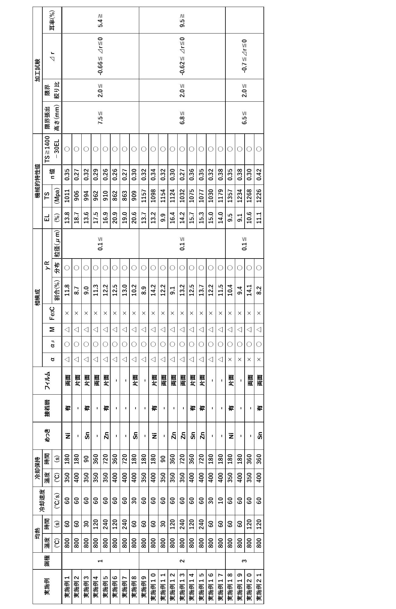
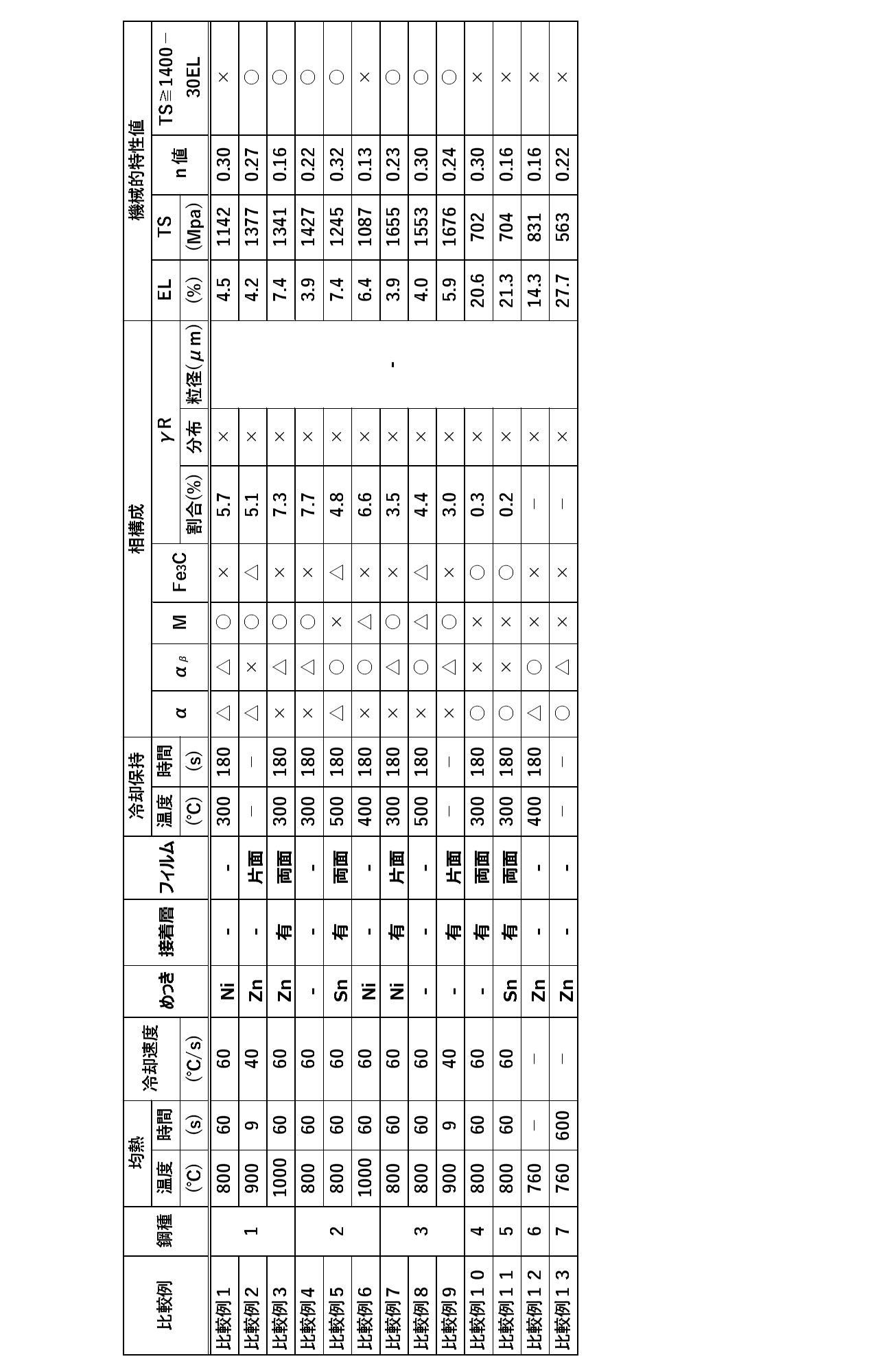
表1に示すスラブ片の鋼種について、鋼種1~3は本発明の成分範囲に入るスラブ片であるが、鋼種4~6は本発明の成分範囲外のスラブ片である。これら鋼種1~6のスラブ片を用いて実施例及び比較例の各値を得た。
表2に示す熱間圧延後の熱延鋼板の機械的特性に関して、鋼種2と鋼種4について特性を示した。鋼種2は、巻取り温度(CT)が700℃以上であるため、引張強度(TS)が900MPa以下の特性を得ることができている。
一方で、鋼種4は巻取り温度(CT)が480℃と低い為、引張強度(TS)が1034MPaと高くなった。その結果、その後の冷間圧延の際に目標とする0.6mm以下まで薄くすることができず、圧延回数と圧延荷重を増大させると割れが生じたため、冷間圧延を中止した。なお、鋼種5~7については、巻き取り温度が低いため硬質化して冷間圧延時に割れが生じる可能性があるため、巻き取り温度を変化させた試験は不実施とした。本発明では、冷延時の負荷を低減する為に、熱間圧延後の引張強度が900MPa以下である場合を良好と判断した。
また表2において、「FT(Finishing Temperature)」は仕上げ圧延機出側のコイル温度を示し、「YP(Yield Point)」は降伏点を示し、「EL(Elongation)は破断伸びを示している。
表4に示す結果に関して、比較例1,3,4,7は、均熱ステップの際の保持温度が300℃と低い為、主相がマルテンサイトとなった。その結果、一定以上の残留オーステナイト粒が確保できず、結果的に伸びが不足したため好ましくない結果となった。
比較例2及び比較例9は、均熱ステップに次ぐ冷却ステップにおいて、一定時間の保持を行わなかったため、一定以上の残留オーステナイト粒が確保できず、特性を満足しなかった。
比較例5及び比較例8は、冷却ステップにおける保持温度が高すぎる為、一定以上の残留オーステナイト粒が確保できず特性を満足しなかった。
比較例6は、均熱ステップにおける均熱温度がAc3変態点以上であったため、Ac3変態点以下の場合とは相構成が異なり、結果的に残留オーステナイト粒の量を満足することができなかった。
比較例10及び比較例11は、スラブ片にCrを一定量以上添加したため、Ac1変態点が上昇した。その結果、800℃の均熱温度では、ベイナイト相及びオーステナイト相が得られず、フェライト相が主相となった。結果的に強度・延性バランスを満足する冷延鋼板を得ることができなかった。
比較例12は、スラブ片においてオーステナイト安定元素であるSiが不足している為、一定の残留オーステナイト粒が確保できなかった。結果的に、強度・延性バランスを満足する冷延鋼板を得ることができなかった。
比較例13はC量及びSi量が少ないため、一定の残留オーステナイト粒が得られず、フェライトが主相となった。その結果、強度を満足する冷延鋼板を得ることができなかった。
以上から明らかなとおり、本発明の実施例では表に示す相構成、機械的特性値、成形性の基準を満たすことで、成形性に優れた高強度冷延鋼板が得られている。一方で、比較例では適正な条件で製造していないため、相構成、機械的特性、成形性の基準のいずれかを満たしておらず、成形性に優れた高強度冷延鋼板として満足しないものであると判断された。
なお上記した実施形態と各実施例は、本発明の趣旨を逸脱しない範囲で種々の変形が可能であることは言うまでもない。
以上説明したように、本発明の熱延鋼板及び冷延鋼板並びにこれらの製造方法によれば、成形性に優れた高強度冷延鋼板やその素材となる熱延鋼板を得ることができる。このうち本発明の高強度冷延鋼板は、薄板としてプレス成形等で小型部品等に成形した場合でも割れが生じることなく成形性に優れる。さらに本発明の高強度冷延鋼板は、成形品の小型化及び軽量化の要請を実現することができ、産業上の利用可能性が極めて高い。
本発明の高強度冷延鋼板は、自動車のガソリンエンジンのガスケット、ノートパソコンやスマートフォンの筐体、電子機器のフレーム部品等に用いることができる。
本発明の高強度冷延鋼板は、自動車のガソリンエンジンのガスケット、ノートパソコンやスマートフォンの筐体、電子機器のフレーム部品等に用いることができる。
1 仕上げ圧延機
F4・F5・F6 異径ロールミル
4a・4b ワークロール
4c・4d バックアップロール
11・12・13 水冷手段
20a・20b 水冷手段
F4・F5・F6 異径ロールミル
4a・4b ワークロール
4c・4d バックアップロール
11・12・13 水冷手段
20a・20b 水冷手段
Claims (16)
- 質量%での含有量として、C:0.1~0.3%、Si:1.0~2.0%、Mn:1.0~2.5%、Cr:0.5%以下、Ni:1.0%以下、P:0.01%以下、S:0.006%以下、N:0.015%以下、Cu:0.5%以下、残部がFeおよび不可避的不純物の組成となる圧延素材を、
合計で30%以上の圧下率で前記圧延素材を粗圧延する第1ステップと、
前記第1ステップの後、800℃以上の温度環境下において互いに径の異なる複数の異径ロールを用いて合計で40%以上の圧下率で前記圧延素材を仕上げ圧延する第2ステップと、
前記第2ステップの後、700℃以上の温度環境下において前記圧延素材の巻き取りを行うことで引張強度が900MPa以下の熱延鋼板を製造する第3ステップと、
を含むことを特徴とする熱延鋼板の製造方法。 - 前記第1ステップにおいては、1100℃以上の温度環境下において前記圧延素材に対して粗圧延を行う請求項1に記載の熱延鋼板の製造方法。
- 前記第2ステップにおいては、仕上げ前段における圧延機1台当りの平均圧下率が40%以上となり、且つ、仕上げ後段における圧延機による圧下の累積歪が0.5以上となるように仕上げ圧延を行う請求項1または2に記載の熱延鋼板の製造方法。
- 請求項1~3のいずれか一項に記載の熱延鋼板の製造法により得られた熱延鋼板を、冷間圧延して冷延鋼板を製造する第4ステップを含むことを特徴とする高強度冷延鋼板の製造方法。
- 前記第4ステップにおいて、合計で60%以上の圧下率で前記熱延鋼板を冷間圧延する請求項4に記載の高強度冷延鋼板の製造方法。
- 前記第4ステップの後、Ac1点以上の均熱温度で前記冷延鋼板を焼鈍した後に冷却保持する第5ステップを更に有する請求項5に記載の高強度冷延鋼板の製造方法。
- 前記熱延鋼板の厚みが1.2~3.0mmであり、前記冷延鋼板の厚みが0.01~0.6mmである請求項4~6のいずれか一項に記載の高強度冷延鋼板の製造方法。
- 質量%での含有量として、C:0.1~0.3%、Si:1.0~2.0%、Mn:1.0~2.5%、Cr:0.5%以下、Ni:1.0%以下、P:0.01%以下、S:0.006%以下、N:0.015%以下、Cu:0.5%以下、残部がFeおよび不可避的不純物の組成を有し、
厚さが1.2~3.0mmであり、引張強度が900MPa以下であることを特徴とする熱延鋼板。 - 質量%での含有量として、C:0.1~0.3%、Si:1.0~2.0%、Mn:1.0~2.5%、Cr:0.5%以下、Ni:1.0%以下、P:0.01%以下、S:0.006%以下、N:0.015%以下、Cu:0.5%以下、残部がFeおよび不可避的不純物の組成を有し、
主相をベイナイト組織とし、さらに前記ベイナイト組織以外にフェライト組織、マルテンサイト組織及び残留オーステナイト組織を含み、
10μm平方の単位面積当たりに10μm未満の残留オーステナイト粒が1個以上分散され、
引張り強度TSが700MPa以上1400MPa以下であり、且つ、
破断伸びをEL%としたとき、
TS≧1400-(30×EL)
を満足することを特徴とする高強度冷延鋼板。 - 前記高強度冷延鋼板における加工硬化の特性を示すn値が0.20以上である請求項9に記載の高強度冷延鋼板。
- 前記残留オーステナイト組織が占める体積割合が8%以上である請求項9又は10に記載の高強度冷延鋼板。
- 前記高強度冷延鋼板における厚みが0.01~0.6mmである請求項9~11のいずれか一項に記載の高強度冷延鋼板。
- 前記高強度冷延鋼板における限界張出高さが6.5mm以上である請求項9~12のいずれか一項に記載の高強度冷延鋼板。
- 前記高強度冷延鋼板における限界絞り比が2.0以上である請求項9~13のいずれか一項に記載の高強度冷延鋼板。
- 前記高強度冷延鋼板におけるΔrが±0.7の範囲である請求項9~14のいずれか一項に記載の高強度冷延鋼板。
- 前記高強度冷延鋼板における耳率が10%以下である請求項9~15のいずれか一項に記載の高強度冷延鋼板。
Priority Applications (3)
| Application Number | Priority Date | Filing Date | Title |
|---|---|---|---|
| CN201980043236.4A CN112313352B (zh) | 2018-06-29 | 2019-06-27 | 热轧钢板、高强度冷轧钢板及它们的制造方法 |
| JP2020527642A JP7217274B2 (ja) | 2018-06-29 | 2019-06-27 | 熱延鋼板、高強度冷延鋼板およびそれらの製造方法 |
| KR1020207037927A KR102685387B1 (ko) | 2018-06-29 | 2019-06-27 | 열연 강판, 고강도 냉연 강판, 및 그것들의 제조 방법 |
Applications Claiming Priority (2)
| Application Number | Priority Date | Filing Date | Title |
|---|---|---|---|
| JP2018124343 | 2018-06-29 | ||
| JP2018-124343 | 2018-06-29 |
Publications (1)
| Publication Number | Publication Date |
|---|---|
| WO2020004561A1 true WO2020004561A1 (ja) | 2020-01-02 |
Family
ID=68984637
Family Applications (1)
| Application Number | Title | Priority Date | Filing Date |
|---|---|---|---|
| PCT/JP2019/025644 Ceased WO2020004561A1 (ja) | 2018-06-29 | 2019-06-27 | 熱延鋼板、高強度冷延鋼板およびそれらの製造方法 |
Country Status (5)
| Country | Link |
|---|---|
| JP (1) | JP7217274B2 (ja) |
| KR (1) | KR102685387B1 (ja) |
| CN (1) | CN112313352B (ja) |
| TW (1) | TWI809136B (ja) |
| WO (1) | WO2020004561A1 (ja) |
Cited By (1)
| Publication number | Priority date | Publication date | Assignee | Title |
|---|---|---|---|---|
| WO2022234760A1 (ja) * | 2021-05-07 | 2022-11-10 | 株式会社神戸製鋼所 | 冷間圧延用の鋼板の製造方法および冷間圧延鋼板の製造方法 |
Citations (9)
| Publication number | Priority date | Publication date | Assignee | Title |
|---|---|---|---|---|
| JP2004183057A (ja) * | 2002-12-04 | 2004-07-02 | Nippon Steel Corp | 形状凍結性に優れた鋼板及びその製造方法 |
| JP2005230896A (ja) * | 2004-02-23 | 2005-09-02 | Nakayama Steel Works Ltd | 高強度薄鋼板およびその製造方法 |
| JP2005262255A (ja) * | 2004-03-17 | 2005-09-29 | Kawasaki Heavy Ind Ltd | 熱延鋼帯製造設備、同設備の構成方法および熱延鋼帯製造方法 |
| JP2006207018A (ja) * | 2004-12-28 | 2006-08-10 | Kobe Steel Ltd | 耐水素脆化特性に優れた超高強度薄鋼板 |
| JP2011168861A (ja) * | 2010-02-22 | 2011-09-01 | Jfe Steel Corp | 高強度熱延鋼板およびその製造方法 |
| WO2011111333A1 (ja) * | 2010-03-09 | 2011-09-15 | Jfeスチール株式会社 | 高強度プレス部材およびその製造方法 |
| WO2013047819A1 (ja) * | 2011-09-30 | 2013-04-04 | 新日鐵住金株式会社 | 引張最大強度980MPa以上を有する材質異方性の少ない成形性に優れた高強度溶融亜鉛めっき鋼板、高強度合金化溶融亜鉛めっき鋼板及びその製造方法 |
| JP2015151576A (ja) * | 2014-02-13 | 2015-08-24 | 新日鐵住金株式会社 | 引張最大強度1300MPa以上を有する成形性に優れた高強度鋼板、高強度溶融亜鉛めっき鋼板、及び、高強度合金化溶融亜鉛めっき鋼板とそれらの製造方法 |
| JP2017128750A (ja) * | 2016-01-18 | 2017-07-27 | 新日鐵住金株式会社 | クラッド板および誘導加熱調理器用器物 |
Family Cites Families (14)
| Publication number | Priority date | Publication date | Assignee | Title |
|---|---|---|---|---|
| JPS5717631U (ja) | 1980-07-04 | 1982-01-29 | ||
| JP4292986B2 (ja) * | 2003-04-16 | 2009-07-08 | Jfeスチール株式会社 | 高張力冷延鋼板およびその製造方法 |
| JP5214905B2 (ja) * | 2007-04-17 | 2013-06-19 | 株式会社中山製鋼所 | 高強度熱延鋼板およびその製造方法 |
| JP5040475B2 (ja) * | 2007-06-29 | 2012-10-03 | Jfeスチール株式会社 | 加工性に優れ、かつ熱処理後の強度靭性に優れた厚肉熱延鋼板およびその製造方法 |
| WO2011004554A1 (ja) * | 2009-07-08 | 2011-01-13 | 東洋鋼鈑株式会社 | プレス成形性に優れた冷延鋼板の製造方法及び冷延鋼板 |
| JP5719545B2 (ja) | 2010-08-13 | 2015-05-20 | 新日鐵住金株式会社 | 伸びとプレス成形安定性に優れた高強度薄鋼板 |
| JP5685166B2 (ja) | 2011-03-31 | 2015-03-18 | 株式会社神戸製鋼所 | 加工性に優れた高強度鋼板およびその製造方法 |
| JP5440672B2 (ja) | 2011-09-16 | 2014-03-12 | Jfeスチール株式会社 | 加工性に優れた高強度鋼板およびその製造方法 |
| JP5884476B2 (ja) * | 2011-12-27 | 2016-03-15 | Jfeスチール株式会社 | 曲げ加工性に優れた高張力熱延鋼板およびその製造方法 |
| US20160068937A1 (en) * | 2013-04-15 | 2016-03-10 | Jfe Steel Corporation | High-strength hot-rolled steel sheet and method for producing the same (as amended) |
| JP5821912B2 (ja) * | 2013-08-09 | 2015-11-24 | Jfeスチール株式会社 | 高強度冷延鋼板およびその製造方法 |
| JP6306481B2 (ja) * | 2014-03-17 | 2018-04-04 | 株式会社神戸製鋼所 | 延性及び曲げ性に優れた高強度冷延鋼板および高強度溶融亜鉛めっき鋼板、並びにそれらの製造方法 |
| WO2016194272A1 (ja) * | 2015-05-29 | 2016-12-08 | Jfeスチール株式会社 | 高強度冷延鋼板、高強度めっき鋼板及びこれらの製造方法 |
| TWI622654B (zh) * | 2016-12-08 | 2018-05-01 | Nippon Steel & Sumitomo Metal Corp | High strength steel plate |
-
2019
- 2019-06-27 JP JP2020527642A patent/JP7217274B2/ja active Active
- 2019-06-27 WO PCT/JP2019/025644 patent/WO2020004561A1/ja not_active Ceased
- 2019-06-27 KR KR1020207037927A patent/KR102685387B1/ko active Active
- 2019-06-27 CN CN201980043236.4A patent/CN112313352B/zh active Active
- 2019-06-28 TW TW108122857A patent/TWI809136B/zh active
Patent Citations (9)
| Publication number | Priority date | Publication date | Assignee | Title |
|---|---|---|---|---|
| JP2004183057A (ja) * | 2002-12-04 | 2004-07-02 | Nippon Steel Corp | 形状凍結性に優れた鋼板及びその製造方法 |
| JP2005230896A (ja) * | 2004-02-23 | 2005-09-02 | Nakayama Steel Works Ltd | 高強度薄鋼板およびその製造方法 |
| JP2005262255A (ja) * | 2004-03-17 | 2005-09-29 | Kawasaki Heavy Ind Ltd | 熱延鋼帯製造設備、同設備の構成方法および熱延鋼帯製造方法 |
| JP2006207018A (ja) * | 2004-12-28 | 2006-08-10 | Kobe Steel Ltd | 耐水素脆化特性に優れた超高強度薄鋼板 |
| JP2011168861A (ja) * | 2010-02-22 | 2011-09-01 | Jfe Steel Corp | 高強度熱延鋼板およびその製造方法 |
| WO2011111333A1 (ja) * | 2010-03-09 | 2011-09-15 | Jfeスチール株式会社 | 高強度プレス部材およびその製造方法 |
| WO2013047819A1 (ja) * | 2011-09-30 | 2013-04-04 | 新日鐵住金株式会社 | 引張最大強度980MPa以上を有する材質異方性の少ない成形性に優れた高強度溶融亜鉛めっき鋼板、高強度合金化溶融亜鉛めっき鋼板及びその製造方法 |
| JP2015151576A (ja) * | 2014-02-13 | 2015-08-24 | 新日鐵住金株式会社 | 引張最大強度1300MPa以上を有する成形性に優れた高強度鋼板、高強度溶融亜鉛めっき鋼板、及び、高強度合金化溶融亜鉛めっき鋼板とそれらの製造方法 |
| JP2017128750A (ja) * | 2016-01-18 | 2017-07-27 | 新日鐵住金株式会社 | クラッド板および誘導加熱調理器用器物 |
Cited By (3)
| Publication number | Priority date | Publication date | Assignee | Title |
|---|---|---|---|---|
| WO2022234760A1 (ja) * | 2021-05-07 | 2022-11-10 | 株式会社神戸製鋼所 | 冷間圧延用の鋼板の製造方法および冷間圧延鋼板の製造方法 |
| JP2022172888A (ja) * | 2021-05-07 | 2022-11-17 | 株式会社神戸製鋼所 | 冷間圧延用の鋼板の製造方法および冷間圧延鋼板の製造方法 |
| JP7770781B2 (ja) | 2021-05-07 | 2025-11-17 | 株式会社神戸製鋼所 | 冷間圧延用の鋼板の製造方法および冷間圧延鋼板の製造方法 |
Also Published As
| Publication number | Publication date |
|---|---|
| TWI809136B (zh) | 2023-07-21 |
| KR20210028610A (ko) | 2021-03-12 |
| CN112313352B (zh) | 2023-06-27 |
| JP7217274B2 (ja) | 2023-02-02 |
| CN112313352A (zh) | 2021-02-02 |
| JPWO2020004561A1 (ja) | 2021-08-02 |
| KR102685387B1 (ko) | 2024-07-17 |
| TW202012642A (zh) | 2020-04-01 |
Similar Documents
| Publication | Publication Date | Title |
|---|---|---|
| JP4738735B2 (ja) | 超高張力鋼シート、超高張力鋼シートの製造方法、及び前記方法により得られた超高張力鋼シート | |
| CN104093873B (zh) | 热镀锌钢板及其制造方法 | |
| CN110959049B (zh) | 具有良好耐老化性的扁钢产品及其制造方法 | |
| CN104114731B (zh) | 钢板、镀敷钢板和它们的制造方法 | |
| CN111684091B (zh) | 高强度冷轧钢板、高强度镀敷钢板以及它们的制造方法 | |
| KR102302471B1 (ko) | 드로잉 캔용 냉연 강판 및 그 제조 방법 | |
| KR101431316B1 (ko) | 굽힘 가공성이 우수한 냉연 강판, 그 제조 방법 및 그것을 사용한 부재 | |
| CN111527224A (zh) | 高强度钢板及其制造方法 | |
| CN104284995B (zh) | 高强度钢板及其制造方法 | |
| JP5930144B1 (ja) | 絞り缶用鋼板及びその製造方法 | |
| CN104114729B (zh) | 冷轧钢板、镀敷钢板和它们的制造方法 | |
| TW201718906A (zh) | 合金化熔融鍍鋅鋼板及其製造方法 | |
| JPWO2016080344A1 (ja) | 絞り缶用鋼板及びその製造方法 | |
| CN102119235B (zh) | 外观优良的高强度热镀锌钢板及其制造方法 | |
| CN114729427A (zh) | 钢板及镀覆钢板 | |
| JP6699310B2 (ja) | 絞り缶用冷延鋼板及びその製造方法 | |
| JP5094888B2 (ja) | 延性に優れた高強度低比重鋼板の製造方法 | |
| CN111527228B (zh) | 高温特性和常温加工性优异的冷轧钢板及其制造方法 | |
| CN102712982B (zh) | 成形性和形状冻结性优良的冷轧钢板及其制造方法 | |
| JP7564419B2 (ja) | ホットスタンプ部品の製造方法 | |
| JP7217274B2 (ja) | 熱延鋼板、高強度冷延鋼板およびそれらの製造方法 | |
| WO2020080015A1 (ja) | フェライト系ステンレス鋼板およびその製造方法 | |
| CN119932422A (zh) | 一种厚规格屈服强度500MPa级镀锌低合金高强钢带及其生产方法 | |
| WO2023032339A1 (ja) | 鋼板及びその製造方法 | |
| JPH06220546A (ja) | 深絞り性に優れた高強度冷延鋼板の製造方法 |
Legal Events
| Date | Code | Title | Description |
|---|---|---|---|
| 121 | Ep: the epo has been informed by wipo that ep was designated in this application |
Ref document number: 19826394 Country of ref document: EP Kind code of ref document: A1 |
|
| ENP | Entry into the national phase |
Ref document number: 2020527642 Country of ref document: JP Kind code of ref document: A |
|
| NENP | Non-entry into the national phase |
Ref country code: DE |
|
| 122 | Ep: pct application non-entry in european phase |
Ref document number: 19826394 Country of ref document: EP Kind code of ref document: A1 |