WO2020004482A1 - ステータおよびモータ - Google Patents
ステータおよびモータ Download PDFInfo
- Publication number
- WO2020004482A1 WO2020004482A1 PCT/JP2019/025419 JP2019025419W WO2020004482A1 WO 2020004482 A1 WO2020004482 A1 WO 2020004482A1 JP 2019025419 W JP2019025419 W JP 2019025419W WO 2020004482 A1 WO2020004482 A1 WO 2020004482A1
- Authority
- WO
- WIPO (PCT)
- Prior art keywords
- tooth
- radial
- teeth
- stator
- radially
- Prior art date
- Legal status (The legal status is an assumption and is not a legal conclusion. Google has not performed a legal analysis and makes no representation as to the accuracy of the status listed.)
- Ceased
Links
Images



Classifications
-
- H—ELECTRICITY
- H02—GENERATION; CONVERSION OR DISTRIBUTION OF ELECTRIC POWER
- H02K—DYNAMO-ELECTRIC MACHINES
- H02K1/00—Details of the magnetic circuit
- H02K1/06—Details of the magnetic circuit characterised by the shape, form or construction
- H02K1/12—Stationary parts of the magnetic circuit
- H02K1/14—Stator cores with salient poles
Definitions
- the present invention relates to a stator and a motor.
- a motor includes a rotor and a stator.
- the motor can reduce vibration and noise by reducing cogging torque.
- a step skew is provided on a rotor and a stator to reduce cogging torque.
- an object of the present invention is to provide a stator and a motor that can reduce cogging torque without complicating a manufacturing process.
- stator includes an annular core back having a center axis as a center, a first tooth extending radially inward from a radial inner surface of the core back, and a radially inner surface of the core back.
- a second tooth extending inward in the radial direction and arranged in the axial direction with the first tooth, and having a radial inner surface of the first tooth and a radial direction of the second tooth in a cross section perpendicular to the central axis.
- Each of the inner surfaces has an arc shape, and in the cross section, a radius of curvature of a radial inner surface of the first tooth and a radius of curvature of a radial inner surface of the second tooth are different from each other.
- One aspect of the present invention is a motor including the above-described stator, and a rotor that faces the stator with a gap in the radial direction, wherein a radially outer surface of the rotor and the first teeth are formed.
- the radial dimension of the gap provided between the radial inner surface and the radial dimension of the gap provided between the radial outer surface of the rotor and the radial inner surface of the second teeth Are the same as each other.
- the cogging torque can be reduced without complicating the manufacturing process.
- FIG. 1 is a schematic cross-sectional view of a stator and a motor according to one embodiment.
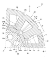
- FIG. 2 is an enlarged cross-sectional view showing a part of the II-II cross section of FIG.
- FIG. 3 is an enlarged sectional view showing a part of the section taken along the line III-III of FIG.
- FIG. 4 is a graph showing a waveform of a cogging torque of the motor according to the embodiment.
- FIG. 5 is a schematic diagram illustrating an electric power steering device using a motor according to one embodiment.
- the axial direction of the central axis J that is, a direction parallel to the vertical direction is simply referred to as “axial direction”
- the radial direction around the central axis J is simply referred to as “radial direction”
- the upper side (+ Z) corresponds to one side in the axial direction
- the lower side (-Z) corresponds to the other side in the axial direction.
- the terms “upper direction”, “upper side” and “lower side” are simply names for describing the relative positional relationships of the respective parts, and the actual arrangement relations and the like are arrangement relations other than the arrangement relations and the like indicated by these names. You may.
- the motor 10 of the present embodiment includes a rotor 20, a stator 30, a housing 11, and a plurality of bearings 15, 16.
- the rotor 20 faces the stator 30 with a gap in the radial direction.
- the rotor 20 includes a shaft 21 having a central axis J, a rotor core 22, and a plurality of magnet parts 23.
- the shaft 21 extends vertically along the central axis J.
- the shaft 21 has a cylindrical shape extending in the axial direction.
- the shaft 21 is rotatably supported around a central axis J by a plurality of bearings 15 and 16.
- the plurality of bearings 15 and 16 are arranged at intervals in the axial direction, and are supported by the housing 11.
- the housing 11 is cylindrical.
- the shaft 21 is fixed to the rotor core 22 by press-fitting or bonding. That is, the rotor core 22 is fixed to the shaft 21.
- the shaft 21 may be fixed to the rotor core 22 via a resin member or the like. That is, the shaft 21 is directly or indirectly fixed to the rotor core 22.
- the shaft 21 is not limited to the above-mentioned cylindrical shape, and may be, for example, a cylindrical shape.
- the rotor core 22 is, for example, a laminated steel sheet formed by laminating a plurality of electromagnetic steel sheets in the axial direction.
- the rotor core 22 is cylindrical.
- the outer shape of the rotor core 22 is polygonal when viewed from the axial direction.
- the radially outer surface of the rotor core 22 has a plurality of flat portions 22a arranged in the circumferential direction.
- the outer shape of the rotor core 22 is an octagon.
- the radial outer surface of the rotor core 22 has eight flat portions 22a arranged in the circumferential direction.
- the flat portion 22a has a flat shape extending in a direction perpendicular to the radial direction.
- the flat portion 22a has a square shape when viewed from the outside in the radial direction.
- the flat portion 22a extends in the axial direction on a radially outer surface of the rotor core 22.
- the flat portion 22a is disposed on the radially outer surface of the rotor core 22 over the entire length in the axial direction.
- the axial length of the flat portion 22a is larger than the circumferential length.
- the rotor core 22 has a through hole 22h, a hole 22b, and a groove 22c. When viewed from the axial direction, the through hole 22h is arranged at the center of the rotor core 22. The through hole 22h penetrates the rotor core 22 in the axial direction. The shaft 21 is inserted into the through hole 22h.
- the hole 22b penetrates the rotor core 22 in the axial direction.
- the plurality of holes 22b are arranged on the rotor core 22 at intervals in the circumferential direction.
- the holes 22b are arranged in the rotor core 22 at equal intervals in the circumferential direction.
- the hole 22b has a circular shape. According to the present embodiment, the rotor core 22 is lightened by the holes 22b, so that the weight and material cost of the rotor core 22 can be reduced.
- the groove 22c is recessed radially inward from the radially outer surface of the rotor core 22 and extends in the axial direction.
- the groove 22c is arranged on the radially outer surface of the rotor core 22 over the entire length in the axial direction.
- the groove portion 22c is arranged between a pair of circumferentially adjacent flat portions 22a on the radially outer surface of the rotor core 22 and opens radially outward.
- the plurality of grooves 22c are arranged on the rotor core 22 at intervals in the circumferential direction.
- the grooves 22c are arranged on the rotor core 22 at equal intervals in the circumferential direction.
- the groove width of the groove portion 22c decreases toward the outside in the radial direction. When viewed from the axial direction, the groove 22c has a wedge shape.
- the magnet unit 23 is a permanent magnet.
- the plurality of magnet portions 23 are provided on the radially outer surface of the rotor core 22.
- the plurality of magnet portions 23 are arranged in a circumferential direction on a radially outer surface of the rotor core 22.
- the plurality of magnet units 23 are arranged at intervals in the circumferential direction. In the present embodiment, the plurality of magnet units 23 are arranged at equal intervals in the circumferential direction.
- the magnet portion 23 is disposed on the radially outer surface of the rotor core 22 over the entire length in the axial direction.
- the magnet part 23 is provided on the flat part 22a.
- the axial length of the magnet portion 23 is the same as the axial length of the flat portion 22a.
- the circumferential width of the magnet portion 23 is smaller than the circumferential width of the flat portion 22a.
- the circumferential positions at both ends in the circumferential direction of the flat portion 22a are respectively slightly outside in the circumferential direction than the circumferential positions at both ends in the circumferential direction of the magnet portion 23.
- a groove 22c is arranged between a pair of magnets 23 adjacent in the circumferential direction.
- the magnet part 23 constitutes a part (part) of the radially outer surface of the rotor 20. That is, the radial outer surface 23a of the magnet portion 23 is a part of the radial outer surface of the rotor 20.
- the magnet section 23 of the present embodiment is a surface magnet type (Surface @ Permanent @ Magnet: SPM).
- the magnet part 23 has a plate shape.
- the plate surface of the magnet unit 23 faces in the radial direction.
- the magnet 23 has a square shape when viewed from the radial direction.
- the magnet portion 23 has a circumferential length greater than a radial length. The thickness of the magnet portion 23 in the radial direction increases from both ends in the circumferential direction of the magnet portion 23 toward the center portion in the circumferential direction (inward in the circumferential direction).
- the radially inner side surface of the magnet portion 23 is straight.
- the radially inner side surface of the magnet portion 23 has a flat shape extending in a direction perpendicular to the radial direction.
- the radially inner side surface of the magnet portion 23 has a square shape when viewed from the radially inner side.
- the radially inner side surface of the magnet portion 23 contacts the flat portion 22a.
- the radially outer surface 23a of the magnet portion 23 has a convex curve shape.
- the radially outer surface 23a of the magnet portion 23 has a curved surface that is radially outwardly convex in a cross section. 2 and 3 is an imaginary circle passing through at least a part of the radial outer surface 23a of the magnet portion 23 and having the center axis J as a center in the cross section.
- the radially outer surface 23a of the magnet portion 23 extends along the virtual circle VC.
- the radial outer surface 23a of the magnet portion 23 is located on the virtual circle VC over the entire circumferential area of the radial outer surface 23a in the cross section. That is, in the cross section, the radius of curvature of the radially outer surface 23a and the radius of the virtual circle VC are the same.
- the radial outer surface 23a has a square shape when viewed from the radial outside.
- the radially outer surface 23a radially opposes first teeth 33 and second teeth 34 of the stator 30, which will be described later. That is, the radial outer surface of the rotor 20 faces the first teeth 33 and the second teeth 34 in the radial direction.
- the stator 30 has a stator core 31, an insulator 30Z, and a plurality of coils 30C.
- Stator core 31 is annular with center axis J as the center.
- Stator core 31 surrounds rotor 20 radially outside rotor 20.
- the stator core 31 faces the rotor 20 with a gap in the radial direction.
- the stator core 31 is, for example, a laminated steel sheet formed by laminating a plurality of electromagnetic steel sheets in the axial direction.
- Stator core 31 has core back 32, first teeth 33, and second teeth 34. That is, the stator 30 includes the core back 32, the first teeth 33, and the second teeth 34.
- the core back 32 has an annular shape centered on the central axis. In the present embodiment, the core back 32 is cylindrical.
- the core back 32 may be, for example, a polygonal cylinder when viewed from the axial direction.
- the radially outer surface of the core back 32 is fixed to the inner peripheral surface of the peripheral wall of the housing 11.
- the core back 32 includes a first core back portion 37 and a second core back portion 38.
- the first core back portion 37 and the second core back portion 38 are arranged side by side in the axial direction.
- the first core back portion 37 and the second core back portion 38 are in contact with each other in the axial direction.
- the first core back portion 37 is annular with the center axis J as the center.
- the first core back portion 37 is disposed in a first portion (first step, first region) S1 of the stator 30 along the axial direction.
- the first core back portion 37 has a first groove 39s on a radially outer surface.
- the first groove 39s is recessed radially inward on the radially outer surface of the first core back portion 37 and extends in the axial direction.
- the first groove 39s extends over the entire length in the axial direction on the radially outer surface of the first core back portion 37.
- the plurality of first grooves 39s are arranged on the radially outer surface of the first core back portion 37 at intervals in the circumferential direction. When viewed from the radial direction, the first groove 39s is arranged so as to overlap the first teeth 33.
- the second core back portion 38 has an annular shape centered on the central axis J.
- the second core back portion 38 is disposed in a second portion (second step, second region) S2 of the stator 30 that is different from the first portion S1 along the axial direction.
- the second core back portion 38 has a second groove 39t on a radially outer surface.
- the second groove 39t is recessed radially inward on the radially outer surface of the second core back portion 38 and extends in the axial direction.
- the second groove 39t extends over the entire length in the axial direction on the radially outer surface of the second core back portion 38.
- the plurality of second grooves 39t are arranged on the radially outer surface of the second core back portion 38 at intervals in the circumferential direction.
- the second groove 39t When viewed from the radial direction, the second groove 39t is arranged so as to overlap the second tooth 34. When viewed from the axial direction, the first groove 39s and the second groove 39t are arranged so as to overlap. The first groove 39s and the second groove 39t are connected in the axial direction.
- the first teeth 33 extend radially inward from the radial inner surface of the first core back portion 37. That is, the first teeth 33 extend radially inward from the radially inner side surface of the core back 32.
- the plurality of first teeth 33 are provided on the radially inner side surface of the first core back portion 37.
- the plurality of first teeth 33 are arranged on the radially inner side surface of the first core back portion 37 at intervals in the circumferential direction. That is, a plurality of the first teeth 33 are arranged in the first portion S1 along the axial direction at intervals in the circumferential direction. In the present embodiment, the plurality of first teeth 33 are arranged at equal intervals in the circumferential direction.
- the first tooth 33 has a first umbrella 35.
- the first umbrella 35 is arranged at a radially inner end of the first teeth 33.
- the first umbrella 35 protrudes from both sides (one side and the other side) in the circumferential direction at a radially inner end of the first tooth 33 than a part other than the radially inner end.
- the radial inner surface of the first umbrella 35 is the radial inner surface 33 a of the first tooth 33.
- a circumferential gap D1 is provided between a pair of first umbrellas 35 adjacent in the circumferential direction. That is, the gap D1 is provided between the pair of first teeth 33 adjacent in the circumferential direction in the first portion S1.
- the gap D1 may be referred to as a first slot open D1.
- the radially inner side surface of the first umbrella 35 is arc-shaped. That is, in the cross section, the radially inner side surface 33a of the first tooth 33 has an arc shape. In the present embodiment, in the cross section, the radially inner side surface 33a of the first tooth 33 has an arc shape that protrudes radially inward. That is, in a cross-sectional view perpendicular to the central axis J, the radially inner surface 33a has a convex arc shape.
- a radial inner surface of the first umbrella 35 radially opposes a radial outer surface 23a of the magnet portion 23. That is, the radial inner surface 33a of the first tooth 33 radially opposes the radial outer surface of the rotor 20.
- a radial gap G1 is provided between the radial inner surface 33a of the first tooth 33 and the radial outer surface of the rotor 20.
- the gap G1 is, for example, between a portion located on the radially inner side of the radially inner side surface 33a of the first tooth 33 and a portion located on the radially outer side of the radially outer surface of the rotor 20. This is the radial distance.
- the gap G1 is formed between the circumferential central portion of the radially inner side surface 33a of the first tooth 33 and the radially outer side surface 23a of the magnet portion 23 located on the virtual circle VC. This is the radial distance.
- the second teeth 34 extend radially inward from the radial inner surface of the second core back portion 38. That is, the second teeth 34 extend radially inward from the radially inner side surface of the core back 32.
- the plurality of second teeth 34 are provided on a radially inner side surface of the second core back portion 38.
- the plurality of second teeth 34 are arranged on the radially inner surface of the second core back portion 38 at intervals in the circumferential direction. That is, a plurality of the second teeth 34 are arranged in the second portion S2 along the axial direction at intervals in the circumferential direction. In the present embodiment, the plurality of second teeth 34 are arranged at equal intervals in the circumferential direction.
- the second tooth 34 has a second umbrella 36.
- the second umbrella 36 is arranged at a radially inner end of the second tooth 34.
- the second umbrella 36 protrudes from the radially inner end of the second tooth 34 to both sides in the circumferential direction than a portion other than the radially inner end.
- the radial inner surface of the second umbrella 36 is a radial inner surface 34 a of the second tooth 34.
- a circumferential gap D2 is provided between the pair of second umbrellas 36 that are adjacent in the circumferential direction. That is, the gap D2 is provided between the pair of second teeth 34 adjacent in the circumferential direction in the second portion S2.
- the gap D2 may be referred to as a second slot open D2.
- the radially inner side surface of the second umbrella 36 is arc-shaped. That is, in the cross section, the radially inner side surface 34a of the second tooth 34 has an arc shape. In the present embodiment, in the cross section, the radially inner side surface 34a of the second tooth 34 has an arc shape that protrudes radially inward. That is, in a cross-sectional view perpendicular to the central axis J, the radially inner side surface 34a has a convex arc shape.
- a radial inner surface of the second umbrella 36 radially opposes a radial outer surface 23a of the magnet portion 23. That is, the radial inner surface 34a of the second tooth 34 radially opposes the radial outer surface of the rotor 20.
- a radial gap G2 is provided between the radial inner surface 34a of the second tooth 34 and the radial outer surface of the rotor 20.
- the gap G2 is, for example, between a portion located on the radially innermost side of the radially inner side surface 34a of the second tooth 34 and a portion located on the radially outermost side of the radially outer surface of the rotor 20. This is the radial distance.
- the gap G2 is formed between the central portion in the circumferential direction on the radial inner surface 34a of the second tooth 34 and the radial outer surface 23a of the magnet portion 23 located on the virtual circle VC. This is the radial distance.
- the first teeth 33 and the second teeth 34 are arranged in the axial direction. When viewed from the axial direction, the first teeth 33 and the second teeth 34 are arranged so as to overlap each other. In a cross section perpendicular to the central axis J, the radius of curvature of the radial inner side surface 33a of the first tooth 33 and the radius of curvature of the radial inner side surface 34a of the second tooth 34 are different from each other. In the example of the present embodiment, the radius of curvature of the radially inner side surface 33a of the first tooth 33 in the cross section is larger than the radius of curvature of the radially inner side surface 34a of the second tooth 34. The radial thickness of the first teeth 33 in the first umbrella 35 is smaller than the radial thickness of the second teeth 34 in the second umbrella 36.
- FIG. 4 is a graph showing the waveform of the cogging torque of the motor 10 including the stator 30 of the present embodiment.
- an anti-phase is generated in the cogging torque without applying a skew to the magnet section 23 or applying a skew to the first teeth 33 and the second teeth 34.
- the waveform C1 of the cogging torque generated in the first portion S1 and the waveform C2 of the cogging torque generated in the second portion S2 are generated in phases opposite to each other.
- the fluctuation width of CS (the difference between the maximum value and the minimum value of the combined cogging torque waveform CS) can be suppressed to a small value. Therefore, according to the present embodiment, the cogging torque can be reduced without complicating the manufacturing process. Then, vibration and noise generated by the motor 10 can be reduced.
- the radial position of the radially innermost portion of the radial inner side surface 33a of the first tooth 33 and the radial position of the radially innermost portion of the radial inner side surface 34a of the second tooth 34 are the same as each other. That is, the radial position of the circumferential central portion on the radial inner surface of the first umbrella 35 and the radial position of the circumferential central portion on the radial inner surface of the second umbrella 36 are the same as each other.
- the radial dimension of the gap G1 provided between the radial outer surface of the rotor 20 and the radial inner surface 33a of the first teeth 33, and the radial direction of the radial outer surface of the rotor 20 and the radial direction of the second teeth 34 The radial dimension of the gap G2 provided between the inner surface 34a and the inner surface 34a is the same. Therefore, the above-described operation and effect of the present embodiment can be more stably obtained.
- the width dimension W1 of the radial inner surface 33a of the first tooth 33 along the circumferential direction is the same as the width dimension W2 of the radial inner surface 34a of the second tooth 34 along the circumferential direction. That is, the circumferential length of the radial inner surface of the first umbrella 35 and the circumferential length of the radial inner surface of the second umbrella 36 are the same as each other. Further, the circumferential dimension of the gap D1 provided between the pair of first teeth 33 adjacent in the circumferential direction in the first portion S1 and the distance between the pair of second teeth 34 adjacent in the circumferential direction in the second portion S2. Are the same as each other in the circumferential direction.
- the nozzle of the automatic winding machine (not shown) can be easily moved around the first teeth 33 and the second teeth 34 when the stator 30 is manufactured. That is, the moving path of the nozzle can be simplified, and the conductive wire of the coil 30C can be easily wound around the first teeth 33 and the second teeth 34. Therefore, the manufacture of the stator 30 becomes easy.
- the first teeth 33 and the second teeth 34 arranged in the axial direction are arranged such that their central portions in the circumferential direction overlap with each other when viewed from the axial direction.
- the circumferential position of the circumferential center of the radial inner surface 33a of the first tooth 33 and the circumferential position of the circumferential center of the radial inner surface 34a of the second tooth 34 are the same as each other.
- the first teeth 33 and the second teeth 34 arranged in the axial direction are arranged such that both ends in the circumferential direction overlap with each other when viewed from the axial direction.
- the circumferential positions of both ends in the circumferential direction on the radial inner side surface 33a of the first tooth 33 and the circumferential positions of both circumferential ends on the radial inner side surface 34a of the second tooth 34 are the same as each other. That is, in the first teeth 33 and the second teeth 34 arranged in the axial direction, the circumferential position of one circumferential end of the radial inner surface 33a of the first teeth 33 and the radial direction of the second teeth 34 The circumferential position of one end in the circumferential direction on the inner side surface 34a is the same as each other.
- the circumferential position of the other end in the radial direction on the radial inner surface 33a of the first tooth 33 and the circumferential position of the other end in the circumferential direction on the radial inner surface 34a of the second tooth 34. are the same as each other. That is, the first teeth 33 and the second teeth 34 are not skewed, and the first teeth 33 and the second teeth 34 are arranged straight in the axial direction. According to this embodiment, since the teeth 33 and 34 are not skewed, the manufacture of the stator 30 is easy.
- the number of the first portions S1 and the number of the second portions S2 are the same.
- the first portion S1 and the second portion S2 are arranged alternately in the axial direction and are arranged by the same number.
- the number of the first portions S1 is one and the number of the second portions S2 is one.
- the present invention is not limited to this, and the number of the first portions S1 may be two or more, and the number of the second portions S2 may be two or more.
- the axial length of the first teeth 33 and the axial length of the second teeth 34 are the same as each other.
- the axial length of the first umbrella 35 and the axial length of the second umbrella 36 are the same.
- the axial length of the radial inner surface 33a of the first tooth 33 and the axial length of the radial inner surface 34a of the second tooth 34 are the same. According to the present embodiment, the structure of the stator 30 can be easily simplified. In addition, the above-described effect of reducing the cogging torque can be more stably obtained.
- the insulator 30 ⁇ / b> Z is mounted on the stator core 31.
- the insulator 30 ⁇ / b> Z has a portion that covers the first teeth 33 and the second teeth 34.
- the material of the insulator 30Z is, for example, an insulating material such as a resin.
- the coil 30C is attached to the stator core 31.
- the plurality of coils 30C are mounted on the stator core 31 via the insulator 30Z.
- the plurality of coils 30C are configured by winding a conductor around each set of the first teeth 33 and the second teeth 34 arranged in the axial direction via the insulator 30Z.
- the electric power steering device 100 is mounted on a steering mechanism of a vehicle wheel.
- the electric power steering device 100 is a device that reduces the steering force by hydraulic pressure.
- the electric power steering apparatus 100 includes the motor 10, a steering shaft 114, an oil pump 116, and a control valve 117.
- the steering shaft 114 transmits an input from the steering 111 to an axle 113 having wheels 112.
- the oil pump 116 generates a hydraulic pressure in the power cylinder 115 that transmits the driving force of the hydraulic pressure to the axle 113.
- the control valve 117 controls the oil of the oil pump 116.
- the motor 10 is mounted as a drive source of the oil pump 116.
- the electric power steering device 100 according to the present embodiment includes the motor 10 according to the present embodiment. For this reason, the electric power steering device 100 having the same effect as the above-described motor 10 can be obtained.
- the present invention is not limited to the above-described embodiment, and for example, as described below, a configuration change or the like can be made without departing from the spirit of the present invention.
- the stator 30 may include a total of three at least one first portion S1 and at least one second portion S2 arranged in the axial direction. Note that the sum of the axial lengths of the radial inner side surfaces 33a of the first teeth 33 of each first portion S1 and the axial length of the radial inner side surfaces 34a of the second teeth 34 of each second portion S2. The sum of the lengths is preferably the same.
- the radially outer surface 23a of the magnet portion 23 extends in the circumferential direction on the virtual circle VC centered on the central axis J in the cross section perpendicular to the central axis J.
- the radius of curvature of the radially outer surface 23a may be smaller than the radius of the virtual circle VC.
- the radially outer surface 23a in the cross section has, for example, a circumferential central portion located on the virtual circle VC and going from the circumferential central portion to both sides (one side and the other side) in the circumferential direction. It is located radially inward from the virtual circle VC.
- the radially outer surface 23a of the magnet portion 23 is located radially outward at the central portion in the circumferential direction, and radially inward from the central portion in the circumferential direction toward both sides in the circumferential direction. Also in this case, the operation and effect of the present invention can be obtained.
- the magnet portion 23 is a surface magnet type, and the radial outer surface 23a of the magnet portion 23 forms a part of the radial outer surface of the rotor 20, but is not limited thereto. That is, the rotor 20 may have a magnet unit of an interior magnet type (Interior Permanent Magnet: IPM). In this case, the radial outer surface of the rotor core 22 forms a part of the radial outer surface of the rotor 20.
- IPM Interior Permanent Magnet
- the example in which the first umbrella 35 protrudes from the radially inner end portion of the first tooth 33 to both sides in the circumferential direction from a portion other than the radially inner end portion has been described.
- the circumferential length (width dimension) of the radially inner end of the first tooth 33 and the circumferential length of a portion other than the radially inner end may be the same.
- an example has been given in which the second umbrella 36 protrudes from the radially inner end of the second tooth 34 to both sides in the circumferential direction from a portion other than the radially inner end but the present invention is not limited to this.
- the circumferential length of the radially inner end of the second tooth 34 and the circumferential length of a portion other than the radially inner end may be the same.
- the radial inner side surface 33a of the first tooth 33 and the radial inner side surface 34a of the second tooth 34 are formed in an arc shape that protrudes radially inward. Yes, but not limited to.
- the radial inner side surface 33a of the first tooth 33 and the radial inner side surface 34a of the second tooth 34 may have an arcuate shape recessed outward in the radial direction.
- the radius of curvature of the radially inner side surface 33a of the first tooth 33 and the radius of curvature of the radially inner side surface 34a of the second tooth 34 are different from each other.
- the radially innermost portion of the radially inner side surface 33a of the first tooth 33 is, for example, both ends in the circumferential direction.
- the radially innermost portions of the radially inner side surfaces 34a of the second teeth 34 are, for example, both ends in the circumferential direction.
- the radial positions of both ends in the circumferential direction on the radial inner surface 33a of the first teeth 33 and the radial positions of both circumferential ends on the radial inner surface 34a of the second teeth 34 are the same. is there.
- the motor 10 can be used for various devices such as a pump, a brake, a clutch, a vacuum cleaner, a dryer, a ceiling fan, a washing machine, and a refrigerator.
- DESCRIPTION OF SYMBOLS 10 ... Motor, 20 ... Rotor, 23a ... Radial outside surface, 30 ... Stator, 32 ... Core back, 33 ... 1st teeth, 33a ... Radial inside surface of 1st teeth, 34 ... 2nd teeth, 34a ... No. Radial inner surface of two teeth, D1: gap between a pair of first teeth adjacent in the circumferential direction, D2: gap between a pair of second teeth adjacent in the circumferential direction, G1: radial inner surface of the first tooth G2: A gap between the radially inner surface of the second tooth and the radially outer surface of the rotor, J: A central axis, S1: a first portion, S2 ... The second portion, W1... The width dimension along the circumferential direction of the radially inner surface of the first tooth, W2... The width dimension along the circumferential direction of the radially inner surface of the second tooth
Landscapes
- Engineering & Computer Science (AREA)
- Power Engineering (AREA)
- Iron Core Of Rotating Electric Machines (AREA)
Abstract
本発明のステータの一つの態様は、中心軸を中心とする環状のコアバックと、コアバックの径方向内側面から径方向内側に延びる第1ティースと、コアバックの径方向内側面から径方向内側に延び、第1ティースと軸方向に並ぶ第2ティースと、を備える。中心軸に垂直な横断面において、第1ティースの径方向内側面および第2ティースの径方向内側面は、それぞれ円弧状である。横断面において、第1ティースの径方向内側面の曲率半径と、第2ティースの径方向内側面の曲率半径とが、互いに異なる。
Description
本発明は、ステータおよびモータに関する。
一般に、モータは、ロータとステータとを備える。モータは、コギングトルクを低減させることにより、振動や騒音を抑えることができる。従来のモータは、例えば日本国公開公報特開2004-159492号公報に記載されるように、ロータおよびステータに段スキューを設けてコギングトルクを低減している。
スキューを掛けると製造工程が増えて、生産性が低下する。
本発明は、上記事情に鑑みて、製造工程を複雑にすることなくコギングトルクを低減できるステータおよびモータを提供することを目的の一つとする。
本発明のステータの一つの態様は、中心軸を中心とする環状のコアバックと、前記コアバックの径方向内側面から径方向内側に延びる第1ティースと、前記コアバックの径方向内側面から径方向内側に延び、前記第1ティースと軸方向に並ぶ第2ティースと、を備え、前記中心軸に垂直な横断面において、前記第1ティースの径方向内側面および前記第2ティースの径方向内側面は、それぞれ円弧状であり、前記横断面において、前記第1ティースの径方向内側面の曲率半径と、前記第2ティースの径方向内側面の曲率半径とが、互いに異なる。
また、本発明の一つの態様は、上述のステータと、前記ステータと径方向に隙間をあけて対向するロータと、を備えるモータであって、前記ロータの径方向外側面と前記第1ティースの径方向内側面との間に設けられる隙間の径方向の寸法と、前記ロータの径方向外側面と前記第2ティースの径方向内側面との間に設けられる隙間の径方向の寸法とが、互いに同じである。
本発明の一つの態様のステータおよびモータによれば、製造工程を複雑にすることなくコギングトルクを低減できる。
以下の説明においては、中心軸Jの軸方向、すなわち上下方向と平行な方向を単に「軸方向」と呼び、中心軸Jを中心とする径方向を単に「径方向」と呼び、中心軸Jを中心とする周方向を単に「周方向」と呼ぶ。本実施形態において、上側(+Z)は、軸方向一方側に相当し、下側(-Z)は、軸方向他方側に相当する。なお、上下方向、上側および下側とは、単に各部の相対位置関係を説明するための名称であり、実際の配置関係等は、これらの名称で示される配置関係等以外の配置関係等であってもよい。
図1に示すように、本実施形態のモータ10は、ロータ20と、ステータ30と、ハウジング11と、複数のベアリング15,16と、を備える。ロータ20は、ステータ30と径方向に隙間をあけて対向する。図1~図3に示すように、ロータ20は、中心軸Jを有するシャフト21と、ロータコア22と、複数のマグネット部23と、を備える。
シャフト21は、中心軸Jに沿って上下方向に延びる。本実施形態の例では、シャフト21が、軸方向に延びる円柱状である。シャフト21は、複数のベアリング15,16により、中心軸J回りに回転自在に支持される。複数のベアリング15,16は、軸方向に互いに間隔をあけて配置され、ハウジング11に支持される。ハウジング11は、筒状である。
シャフト21は、ロータコア22に対して、圧入や接着などによって固定される。つまりロータコア22は、シャフト21と固定される。なお、シャフト21は、ロータコア22に対して、樹脂部材などを介して固定されてもよい。すなわち、シャフト21は、ロータコア22と直接または間接的に固定される。シャフト21は、上記円柱状に限らず、例えば筒状でもよい。
ロータコア22は、例えば、複数の電磁鋼板が軸方向に積層されて構成される積層鋼板である。ロータコア22は、筒状である。ロータコア22は、軸方向から見て、外形が多角形状である。ロータコア22の径方向外側面は、周方向に並ぶ複数の平面部22aを有する。本実施形態の例では、ロータコア22の外形が、8角形状である。ロータコア22の径方向外側面は、周方向に並ぶ8つの平面部22aを有する。平面部22aは、径方向に垂直な方向に広がる平面状である。平面部22aは、径方向外側から見て、四角形状である。平面部22aは、ロータコア22の径方向外側面において、軸方向に延びる。平面部22aは、ロータコア22の径方向外側面に、軸方向全長にわたって配置される。本実施形態の例では、平面部22aの軸方向の長さが、周方向の長さよりも大きい。
ロータコア22は、貫通孔22hと、孔部22bと、溝部22cと、を有する。軸方向から見て、貫通孔22hは、ロータコア22の中心部に配置される。貫通孔22hは、ロータコア22を軸方向に貫通する。貫通孔22hには、シャフト21が挿入される。
孔部22bは、ロータコア22を軸方向に貫通する。孔部22bは、ロータコア22に周方向に互いに間隔をあけて複数配置される。本実施形態の例では、孔部22bが、ロータコア22に周方向に等間隔に配列する。軸方向から見て、孔部22bは、円形状である。本実施形態によれば、孔部22bによりロータコア22を肉抜きして、ロータコア22の軽量化および材料費削減を図ることができる。
溝部22cは、ロータコア22の径方向外側面から径方向内側に窪み、軸方向に延びる。溝部22cは、ロータコア22の径方向外側面に、軸方向全長にわたって配置される。溝部22cは、ロータコア22の径方向外側面において、周方向に隣り合う一対の平面部22a同士の間に配置され、径方向外側に開口する。溝部22cは、ロータコア22に周方向に互いに間隔をあけて複数配置される。溝部22cは、ロータコア22に周方向に等間隔に配列する。溝部22cは、径方向外側に向かうにしたがい溝幅が小さくなる。軸方向から見て、溝部22cは、くさび形状である。
マグネット部23は、永久磁石である。マグネット部23は、ロータコア22の径方向外側面に複数設けられる。複数のマグネット部23は、ロータコア22の径方向外側面において、周方向に配列する。複数のマグネット部23は、周方向に互いに間隔をあけて配置される。本実施形態では、複数のマグネット部23が、周方向に等間隔に配列する。マグネット部23は、ロータコア22の径方向外側面に、軸方向全長にわたって配置される。
マグネット部23は、平面部22aに設けられる。マグネット部23の軸方向の長さは、平面部22aの軸方向の長さと同じである。本実施形態の例では、マグネット部23の周方向の幅寸法が、平面部22aの周方向の幅寸法よりも小さい。つまり、平面部22aの周方向の両端の各周方向位置が、マグネット部23の周方向の両端の各周方向位置よりも、それぞれ僅かに周方向の外側に配置される。周方向に隣り合う一対のマグネット部23同士の間には、溝部22cが配置される。マグネット部23は、ロータ20の径方向外側面の一部(部分)を構成する。つまり、マグネット部23の径方向外側面23aは、ロータ20の径方向外側面の一部である。本実施形態のマグネット部23は、表面磁石型(Surface Permanent Magnet:SPM)である。
マグネット部23は、板状である。マグネット部23の板面は、径方向を向く。マグネット部23は、径方向から見て、四角形状である。軸方向から見て、マグネット部23は、周方向の長さが径方向の長さよりも大きい。マグネット部23は、マグネット部23の周方向の両端部から、周方向の中央部側(周方向の内側)に向かうにしたがい、径方向の厚さが大きくなる。
中心軸Jに垂直な横断面(以下、単に横断面という場合がある)において、マグネット部23の径方向内側面は、直線状である。マグネット部23の径方向内側面は、径方向に垂直な方向に広がる平面状である。マグネット部23の径方向内側面は、径方向内側から見て、四角形状である。マグネット部23の径方向内側面は、平面部22aと接触する。
横断面において、マグネット部23の径方向外側面23aは、凸曲線状である。マグネット部23の径方向外側面23aは、横断面において径方向外側に凸となる曲面状である。図2および図3に符号VCで示すものは、横断面において、マグネット部23の径方向外側面23aの少なくとも一部を通り、中心軸Jを中心とする仮想円である。横断面において、マグネット部23の径方向外側面23aは、仮想円VCに沿って延びる。本実施形態の例では、横断面においてマグネット部23の径方向外側面23aが、径方向外側面23aの周方向の全域にわたって、仮想円VC上に位置する。つまり横断面において、径方向外側面23aの曲率半径と、仮想円VCの半径とは、互いに同じである。径方向外側面23aは、径方向外側から見て、四角形状である。径方向外側面23aは、ステータ30の後述する第1ティース33および第2ティース34と、径方向に対向する。つまり、ロータ20の径方向外側面は、第1ティース33および第2ティース34と、径方向に対向する。
ステータ30は、ステータコア31と、インシュレータ30Zと、複数のコイル30Cと、を有する。ステータコア31は、中心軸Jを中心とする環状である。ステータコア31は、ロータ20の径方向外側においてロータ20を囲む。ステータコア31は、ロータ20と径方向に隙間をあけて対向する。ステータコア31は、例えば、複数の電磁鋼板が軸方向に積層されて構成される積層鋼板である。
ステータコア31は、コアバック32と、第1ティース33と、第2ティース34と、を有する。つまり、ステータ30は、コアバック32と、第1ティース33と、第2ティース34と、を有する。コアバック32は、中心軸を中心とする環状である。本実施形態では、コアバック32が円筒状である。コアバック32は、例えば、軸方向から見て多角形の筒状等でもよい。コアバック32の径方向外側面は、ハウジング11の周壁部の内周面と固定される。
コアバック32は、第1コアバック部37と、第2コアバック部38と、を有する。第1コアバック部37と第2コアバック部38とは、軸方向に並んで配置される。第1コアバック部37と第2コアバック部38とは、軸方向に互いに接触する。
第1コアバック部37は、中心軸Jを中心とする環状である。第1コアバック部37は、ステータ30のうち、軸方向に沿う第1の部分(第1の段、第1の領域)S1に配置される。第1コアバック部37は、径方向外側面に第1溝39sを有する。第1溝39sは、第1コアバック部37の径方向外側面において径方向内側に窪み、軸方向に延びる。第1溝39sは、第1コアバック部37の径方向外側面において軸方向の全長にわたって延びる。第1溝39sは、第1コアバック部37の径方向外側面に、周方向に互いに間隔をあけて複数配置される。径方向から見て、第1溝39sは、第1ティース33と重なって配置される。
第2コアバック部38は、中心軸Jを中心とする環状である。第2コアバック部38は、ステータ30のうち、軸方向に沿う第1の部分S1と異なる第2の部分(第2の段、第2の領域)S2に配置される。第2コアバック部38は、径方向外側面に第2溝39tを有する。第2溝39tは、第2コアバック部38の径方向外側面において径方向内側に窪み、軸方向に延びる。第2溝39tは、第2コアバック部38の径方向外側面において軸方向の全長にわたって延びる。第2溝39tは、第2コアバック部38の径方向外側面に、周方向に互いに間隔をあけて複数配置される。径方向から見て、第2溝39tは、第2ティース34と重なって配置される。軸方向から見て、第1溝39sと第2溝39tとは、重なって配置される。第1溝39sと第2溝39tとは、軸方向に繋がる。
第1ティース33は、第1コアバック部37の径方向内側面から、径方向内側に延びる。つまり第1ティース33は、コアバック32の径方向内側面から径方向内側に延びる。第1ティース33は、第1コアバック部37の径方向内側面に複数設けられる。複数の第1ティース33は、第1コアバック部37の径方向内側面に、周方向に互いに間隔をあけて複数配置される。つまり第1ティース33は、軸方向に沿う第1の部分S1に、周方向に互いに間隔をあけて複数配置される。本実施形態では、複数の第1ティース33が、周方向に等間隔に配列する。
第1ティース33は、第1アンブレラ35を有する。第1アンブレラ35は、第1ティース33の径方向内端部に配置される。第1アンブレラ35は、第1ティース33の径方向内端部において、径方向内端部以外の部位よりも周方向の両側(一方側および他方側)に突出する。第1アンブレラ35の径方向内側面は、第1ティース33の径方向内側面33aである。周方向に隣り合う一対の第1アンブレラ35同士の間には、周方向の隙間D1が設けられる。つまり、第1の部分S1において周方向に隣り合う一対の第1ティース33間には、隙間D1が設けられる。隙間D1は、第1スロットオープンD1と言い換えてもよい。
中心軸Jに垂直な横断面において、第1アンブレラ35の径方向内側面は、円弧状である。つまり横断面において、第1ティース33の径方向内側面33aは、円弧状である。本実施形態では、横断面において、第1ティース33の径方向内側面33aが、径方向内側に突出する円弧状である。すなわち、中心軸Jに垂直な横断面視で、径方向内側面33aは、凸円弧状である。
第1アンブレラ35の径方向内側面は、マグネット部23の径方向外側面23aと、径方向に対向する。つまり、第1ティース33の径方向内側面33aは、ロータ20の径方向外側面と、径方向に対向する。第1ティース33の径方向内側面33aとロータ20の径方向外側面との間には、径方向の隙間G1が設けられる。隙間G1は、例えば、第1ティース33の径方向内側面33aのうち最も径方向内側に位置する部分と、ロータ20の径方向外側面のうち最も径方向外側に位置する部分と、の間の径方向の距離である。本実施形態の例では、隙間G1が、第1ティース33の径方向内側面33aにおける周方向の中央部と、仮想円VC上に位置するマグネット部23の径方向外側面23aと、の間の径方向の距離である。
第2ティース34は、第2コアバック部38の径方向内側面から、径方向内側に延びる。つまり第2ティース34は、コアバック32の径方向内側面から径方向内側に延びる。第2ティース34は、第2コアバック部38の径方向内側面に複数設けられる。複数の第2ティース34は、第2コアバック部38の径方向内側面に、周方向に互いに間隔をあけて複数配置される。つまり第2ティース34は、軸方向に沿う第2の部分S2に、周方向に互いに間隔をあけて複数配置される。本実施形態では、複数の第2ティース34が、周方向に等間隔に配列する。
第2ティース34は、第2アンブレラ36を有する。第2アンブレラ36は、第2ティース34の径方向内端部に配置される。第2アンブレラ36は、第2ティース34の径方向内端部において、径方向内端部以外の部位よりも周方向の両側に突出する。第2アンブレラ36の径方向内側面は、第2ティース34の径方向内側面34aである。周方向に隣り合う一対の第2アンブレラ36同士の間には、周方向の隙間D2が設けられる。つまり、第2の部分S2において周方向に隣り合う一対の第2ティース34間には、隙間D2が設けられる。隙間D2は、第2スロットオープンD2と言い換えてもよい。
中心軸Jに垂直な横断面において、第2アンブレラ36の径方向内側面は、円弧状である。つまり横断面において、第2ティース34の径方向内側面34aは、円弧状である。本実施形態では、横断面において、第2ティース34の径方向内側面34aが、径方向内側に突出する円弧状である。すなわち、中心軸Jに垂直な横断面視で、径方向内側面34aは、凸円弧状である。
第2アンブレラ36の径方向内側面は、マグネット部23の径方向外側面23aと、径方向に対向する。つまり、第2ティース34の径方向内側面34aは、ロータ20の径方向外側面と、径方向に対向する。第2ティース34の径方向内側面34aとロータ20の径方向外側面との間には、径方向の隙間G2が設けられる。隙間G2は、例えば、第2ティース34の径方向内側面34aのうち最も径方向内側に位置する部分と、ロータ20の径方向外側面のうち最も径方向外側に位置する部分と、の間の径方向の距離である。本実施形態の例では、隙間G2が、第2ティース34の径方向内側面34aにおける周方向の中央部と、仮想円VC上に位置するマグネット部23の径方向外側面23aと、の間の径方向の距離である。
第1ティース33と第2ティース34とは、軸方向に並ぶ。軸方向から見て、第1ティース33と第2ティース34とは、互いに重なって配置される。中心軸Jに垂直な横断面において、第1ティース33の径方向内側面33aの曲率半径と、第2ティース34の径方向内側面34aの曲率半径とは、互いに異なる。本実施形態の例では、横断面において第1ティース33の径方向内側面33aの曲率半径が、第2ティース34の径方向内側面34aの曲率半径よりも大きい。また、第1ティース33の第1アンブレラ35の径方向の厚さが、第2ティース34の第2アンブレラ36の径方向の厚さよりも小さい。
図4は、本実施形態のステータ30を備えるモータ10の、コギングトルクの波形を示すグラフである。図4に示すように、本実施形態によれば、マグネット部23にスキューを掛けなくても、また第1ティース33および第2ティース34にスキューを掛けなくても、コギングトルクに逆位相を発生させることができる。すなわち、第1の部分S1に発生するコギングトルクの波形C1と、第2の部分S2に発生するコギングトルクの波形C2とが、互いに逆位相で生じるため、これらが互いに打ち消し合い、合成コギングトルク波形CSの変動幅(合成コギングトルク波形CSの最大値と最小値との差)を、小さく抑えることができる。したがって本実施形態によれば、製造工程を複雑にすることなくコギングトルクを低減できる。そして、モータ10が発する振動および騒音を低減できる。
第1ティース33の径方向内側面33aのうち最も径方向内側に位置する部分の径方向位置と、第2ティース34の径方向内側面34aのうち最も径方向内側に位置する部分の径方向位置とは、互いに同じである。すなわち、第1アンブレラ35の径方向内側面における周方向の中央部の径方向位置と、第2アンブレラ36の径方向内側面における周方向の中央部の径方向位置とが、互いに同じである。そして、ロータ20の径方向外側面と第1ティース33の径方向内側面33aとの間に設けられる隙間G1の径方向の寸法と、ロータ20の径方向外側面と第2ティース34の径方向内側面34aとの間に設けられる隙間G2の径方向の寸法とが、互いに同じである。したがって、上述した本実施形態の作用効果がより安定して得られる。
第1ティース33の径方向内側面33aの周方向に沿う幅寸法W1と、第2ティース34の径方向内側面34aの周方向に沿う幅寸法W2とは、互いに同じである。すなわち、第1アンブレラ35の径方向内側面の周方向の長さと、第2アンブレラ36の径方向内側面の周方向の長さとが、互いに同じである。また、第1の部分S1において周方向に隣り合う一対の第1ティース33間に設けられる隙間D1の周方向の寸法と、第2の部分S2において周方向に隣り合う一対の第2ティース34間に設けられる隙間D2の周方向の寸法とが、互いに同じである。本実施形態によれば、ステータ30の製造時に、図示しない自動巻線機のノズルを第1ティース33および第2ティース34回りに移動させやすい。すなわち、ノズルの移動経路を簡素化でき、第1ティース33および第2ティース34にコイル30Cの導線を巻き回しやすくできる。したがって、ステータ30の製造が容易となる。
軸方向に並ぶ第1ティース33と第2ティース34とは、それぞれの周方向の中心部同士が、軸方向から見て互いに重なって配置される。第1ティース33の径方向内側面33aにおける周方向の中心部の周方向位置と、第2ティース34の径方向内側面34aにおける周方向の中心部の周方向位置とは、互いに同じである。また、軸方向に並ぶ第1ティース33と第2ティース34とは、それぞれの周方向の両端部同士が、軸方向から見て互いに重なって配置される。第1ティース33の径方向内側面33aにおける周方向の両端部の周方向位置と、第2ティース34の径方向内側面34aにおける周方向の両端部の周方向位置とは、互いに同じである。すなわち、軸方向に並ぶ第1ティース33と第2ティース34とにおいて、第1ティース33の径方向内側面33aにおける周方向の一方側の端部の周方向位置と、第2ティース34の径方向内側面34aにおける周方向の一方側の端部の周方向位置とは、互いに同じである。また、第1ティース33の径方向内側面33aにおける周方向の他方側の端部の周方向位置と、第2ティース34の径方向内側面34aにおける周方向の他方側の端部の周方向位置とは、互いに同じである。すなわち、第1ティース33および第2ティース34にスキューは掛けられておらず、第1ティース33と第2ティース34とは、軸方向に真っ直ぐに配列する。本実施形態によれば、ティース33,34にスキューが掛けられていないので、ステータ30の製造が容易である。
ステータ30において、第1の部分S1の数と第2の部分S2の数とは、互いに同じである。第1の部分S1および第2の部分S2は、軸方向に交互に並んで同じ数ずつ配置される。本実施形態の例では、第1の部分S1の数が1つであり、第2の部分S2の数が1つである。ただしこれに限らず、第1の部分S1の数が2つ以上であり、第2の部分S2の数が2つ以上であってもよい。また、第1ティース33の軸方向の長さと、第2ティース34の軸方向の長さとは、互いに同じである。第1アンブレラ35の軸方向の長さと、第2アンブレラ36の軸方向の長さとが、互いに同じである。すなわち、第1ティース33の径方向内側面33aの軸方向の長さと、第2ティース34の径方向内側面34aの軸方向の長さとが、同一である。本実施形態によれば、ステータ30の構造を簡素化しやすい。そして、コギングトルクを低減できるという上述の作用効果が、より安定して得られやすい。
インシュレータ30Zは、ステータコア31に装着される。インシュレータ30Zは、第1ティース33および第2ティース34を覆う部分を有する。インシュレータ30Zの材料は、例えば樹脂などの絶縁材料である。
コイル30Cは、ステータコア31に取り付けられる。複数のコイル30Cは、インシュレータ30Zを介してステータコア31に装着される。複数のコイル30Cは、インシュレータ30Zを介して、軸方向に並ぶ第1ティース33および第2ティース34の各組に導線が巻き回されることにより構成される。
次に、本実施形態のモータ10を搭載する装置の一例について説明する。本実施形態においては、モータ10を電動パワーステアリング装置に搭載した例について説明する。
図5に示すように、電動パワーステアリング装置100は、自動車の車輪の操舵機構に搭載される。電動パワーステアリング装置100は、操舵力を油圧により軽減する装置である。本実施形態の電動パワーステアリング装置100は、モータ10と、操舵軸114と、オイルポンプ116と、コントロールバルブ117と、を備える。
操舵軸114は、ステアリング111からの入力を、車輪112を有する車軸113に伝える。オイルポンプ116は、車軸113に油圧による駆動力を伝えるパワーシリンダ115に油圧を発生させる。コントロールバルブ117は、オイルポンプ116のオイルを制御する。電動パワーステアリング装置100において、モータ10は、オイルポンプ116の駆動源として搭載される。
本実施形態の電動パワーステアリング装置100は、本実施形態のモータ10を備える。このため、上述のモータ10と同様の効果を奏する電動パワーステアリング装置100が得られる。
なお、本発明は前述の実施形態に限定されず、例えば下記に説明するように、本発明の趣旨を逸脱しない範囲において構成の変更等が可能である。
前述の実施形態では、ステータ30において第1の部分S1の数と第2の部分S2の数とが、互いに同じである例を挙げたが、これに限らない。第1の部分S1の数と第2の部分S2の数とが、互いに異なっていてもよい。この場合においても、本発明の作用効果が得られる。具体的には、例えば、ステータ30に、少なくとも1つの第1の部分S1および少なくとも1つの第2の部分S2が、軸方向に並んで計3つ配置されてもよい。なお、各第1の部分S1の第1ティース33の径方向内側面33aの軸方向の長さの和と、各第2の部分S2の第2ティース34の径方向内側面34aの軸方向の長さの和とは、互いに同じであることが好ましい。
また、前述の実施形態では、中心軸Jに垂直な横断面において、マグネット部23の径方向外側面23aが、中心軸Jを中心とする仮想円VC上を周方向に延びる例を挙げたが、これに限らない。例えば、横断面において、径方向外側面23aの曲率半径が、仮想円VCの半径より小さくてもよい。この場合、横断面において径方向外側面23aは、例えば周方向の中央部が仮想円VC上に位置し、周方向の中央部から周方向の両側(一方側および他方側)に向かうにしたがい、仮想円VCから径方向内側に離れて位置する。すなわち、マグネット部23の径方向外側面23aは、周方向の中央部が最も径方向外側に位置し、周方向の中央部から周方向の両側に向かうにしたがい径方向内側に位置する。この場合においても、本発明の作用効果が得られる。
また、前述の実施形態では、マグネット部23が表面磁石型であり、マグネット部23の径方向外側面23aが、ロータ20の径方向外側面の一部を構成するが、これに限らない。すなわち、ロータ20は、埋込磁石型(Interior Permanent Magnet:IPM)のマグネット部を有していてもよい。この場合、ロータコア22の径方向外側面が、ロータ20の径方向外側面の一部を構成する。
また、前述の実施形態では、第1アンブレラ35が、第1ティース33の径方向内端部において、径方向内端部以外の部位よりも周方向の両側に突出する例を挙げたが、これに限らない。第1ティース33の径方向内端部の周方向の長さ(幅寸法)と、径方向内端部以外の部位の周方向の長さとが、互いに同じであってもよい。また、第2アンブレラ36が、第2ティース34の径方向内端部において、径方向内端部以外の部位よりも周方向の両側に突出する例を挙げたが、これに限らない。第2ティース34の径方向内端部の周方向の長さと、径方向内端部以外の部位の周方向の長さとが、互いに同じであってもよい。
また、前述の実施形態では、中心軸Jに垂直な横断面において、第1ティース33の径方向内側面33aおよび第2ティース34の径方向内側面34aが、径方向内側に突出する円弧状であるが、これに限らない。中心軸Jに垂直な横断面において、第1ティース33の径方向内側面33aおよび第2ティース34の径方向内側面34aが、径方向外側に凹む円弧状であってもよい。そして横断面において、第1ティース33の径方向内側面33aの曲率半径と、第2ティース34の径方向内側面34aの曲率半径とが、互いに異なる。この場合、第1ティース33の径方向内側面33aのうち最も径方向内側に位置する部分は、例えば周方向の両端部である。また、第2ティース34の径方向内側面34aのうち最も径方向内側に位置する部分は、例えば周方向の両端部である。そして、第1ティース33の径方向内側面33aにおける周方向の両端部の径方向位置と、第2ティース34の径方向内側面34aにおける周方向の両端部の径方向位置とが、互いに同じである。
また、前述の実施形態では、モータ10が電動パワーステアリング装置100に搭載される一例を挙げたが、これに限らない。モータ10は、例えば、ポンプ、ブレーキ、クラッチ、掃除機、ドライヤ、シーリングファン、洗濯機および冷蔵庫などの多様な機器に用いることができる。
その他、本発明の趣旨から逸脱しない範囲において、前述の実施形態、変形例およびなお書き等で説明した各構成(構成要素)を組み合わせてもよく、また、構成の付加、省略、置換、その他の変更が可能である。また本発明は、前述した実施形態によって限定されず、特許請求の範囲によってのみ限定される。
10…モータ、20…ロータ、23a…径方向外側面、30…ステータ、32…コアバック、33…第1ティース、33a…第1ティースの径方向内側面、34…第2ティース、34a…第2ティースの径方向内側面、D1…周方向に隣り合う一対の第1ティース間の隙間、D2…周方向に隣り合う一対の第2ティース間の隙間、G1…第1ティースの径方向内側面とロータの径方向外側面との間の隙間、G2…第2ティースの径方向内側面とロータの径方向外側面との間の隙間、J…中心軸、S1…第1の部分、S2…第2の部分、W1…第1ティースの径方向内側面の周方向に沿う幅寸法、W2…第2ティースの径方向内側面の周方向に沿う幅寸法
Claims (12)
- 中心軸を中心とする環状のコアバックと、
前記コアバックの径方向内側面から径方向内側に延びる第1ティースと、
前記コアバックの径方向内側面から径方向内側に延び、前記第1ティースと軸方向に並ぶ第2ティースと、を備え、
前記中心軸に垂直な横断面において、前記第1ティースの径方向内側面および前記第2ティースの径方向内側面は、それぞれ円弧状であり、
前記横断面において、前記第1ティースの径方向内側面の曲率半径と、前記第2ティースの径方向内側面の曲率半径とが、互いに異なる、ステータ。 - 請求項1に記載のステータであって、
前記横断面において、前記第1ティースの径方向内側面および前記第2ティースの径方向内側面が、径方向内側に突出する円弧状である、ステータ。 - 請求項1に記載のステータであって、
前記横断面において、前記第1ティースの径方向内側面および前記第2ティースの径方向内側面が、径方向外側に凹む円弧状である、ステータ。 - 請求項1~3のいずれか一項に記載のステータであって、
前記第1ティースの径方向内側面のうち最も径方向内側に位置する部分の径方向位置と、前記第2ティースの径方向内側面のうち最も径方向内側に位置する部分の径方向位置とが、互いに同じである、ステータ。 - 請求項1~4のいずれか一項に記載のステータであって、
前記第1ティースの径方向内側面の周方向に沿う幅寸法と、前記第2ティースの径方向内側面の周方向に沿う幅寸法とが、互いに同じである、ステータ。 - 請求項1~5のいずれか一項に記載のステータであって、
前記第1ティースは、軸方向に沿う第1の部分に、周方向に互いに間隔をあけて複数配置され、
前記第2ティースは、軸方向に沿う前記第1の部分と異なる第2の部分に、周方向に互いに間隔をあけて複数配置され、
前記第1の部分において周方向に隣り合う一対の前記第1ティース間に設けられる隙間の周方向の寸法と、前記第2の部分において周方向に隣り合う一対の前記第2ティース間に設けられる隙間の周方向の寸法とが、互いに同じである、ステータ。 - 請求項1~6のいずれか一項に記載のステータであって、
前記第1ティースの径方向内側面における周方向の中心部の周方向位置と、前記第2ティースの径方向内側面における周方向の中心部の周方向位置とが、互いに同じである、ステータ。 - 請求項1~7のいずれか一項に記載のステータであって、
前記第1ティースの径方向内側面における周方向の両端部の周方向位置と、前記第2ティースの径方向内側面における周方向の両端部の周方向位置とが、互いに同じである、ステータ。 - 請求項1~8のいずれか一項に記載のステータであって、
前記第1ティースは、軸方向に沿う第1の部分に、周方向に互いに間隔をあけて複数配置され、
前記第2ティースは、軸方向に沿う前記第1の部分と異なる第2の部分に、周方向に互いに間隔をあけて複数配置され、
前記第1の部分の数と前記第2の部分の数とが、互いに同じである、ステータ。 - 請求項9に記載のステータであって、
前記第1の部分の数が1つであり、前記第2の部分の数が1つである、ステータ。 - 請求項1~8のいずれか一項に記載のステータであって、
前記第1ティースは、軸方向に沿う第1の部分に、周方向に互いに間隔をあけて複数配置され、
前記第2ティースは、軸方向に沿う前記第1の部分と異なる第2の部分に、周方向に互いに間隔をあけて複数配置され、
前記第1の部分の数と前記第2の部分の数とが、互いに異なる、ステータ。 - 請求項1~11のいずれか一項に記載のステータと、
前記ステータと径方向に隙間をあけて対向するロータと、を備えるモータであって、
前記ロータの径方向外側面と前記第1ティースの径方向内側面との間に設けられる隙間の径方向の寸法と、前記ロータの径方向外側面と前記第2ティースの径方向内側面との間に設けられる隙間の径方向の寸法とが、互いに同じである、モータ。
Priority Applications (2)
| Application Number | Priority Date | Filing Date | Title |
|---|---|---|---|
| CN201980043815.9A CN112400268A (zh) | 2018-06-28 | 2019-06-26 | 定子和马达 |
| JP2020527587A JPWO2020004482A1 (ja) | 2018-06-28 | 2019-06-26 | ステータおよびモータ |
Applications Claiming Priority (2)
| Application Number | Priority Date | Filing Date | Title |
|---|---|---|---|
| JP2018123573 | 2018-06-28 | ||
| JP2018-123573 | 2018-06-28 |
Publications (1)
| Publication Number | Publication Date |
|---|---|
| WO2020004482A1 true WO2020004482A1 (ja) | 2020-01-02 |
Family
ID=68986609
Family Applications (1)
| Application Number | Title | Priority Date | Filing Date |
|---|---|---|---|
| PCT/JP2019/025419 Ceased WO2020004482A1 (ja) | 2018-06-28 | 2019-06-26 | ステータおよびモータ |
Country Status (3)
| Country | Link |
|---|---|
| JP (1) | JPWO2020004482A1 (ja) |
| CN (1) | CN112400268A (ja) |
| WO (1) | WO2020004482A1 (ja) |
Citations (4)
| Publication number | Priority date | Publication date | Assignee | Title |
|---|---|---|---|---|
| DE102009019555A1 (de) * | 2009-04-30 | 2010-11-04 | Minebea Co., Ltd. | Eisenkern für eine elektrische Maschine |
| JP2014110660A (ja) * | 2012-11-30 | 2014-06-12 | Daikin Ind Ltd | モータ及び圧縮機 |
| JP2016046879A (ja) * | 2014-08-21 | 2016-04-04 | 三菱電機株式会社 | 回転電機 |
| JP2016167907A (ja) * | 2015-03-09 | 2016-09-15 | 三菱電機株式会社 | 回転電機および電動パワーステアリング装置 |
-
2019
- 2019-06-26 CN CN201980043815.9A patent/CN112400268A/zh active Pending
- 2019-06-26 WO PCT/JP2019/025419 patent/WO2020004482A1/ja not_active Ceased
- 2019-06-26 JP JP2020527587A patent/JPWO2020004482A1/ja not_active Withdrawn
Patent Citations (4)
| Publication number | Priority date | Publication date | Assignee | Title |
|---|---|---|---|---|
| DE102009019555A1 (de) * | 2009-04-30 | 2010-11-04 | Minebea Co., Ltd. | Eisenkern für eine elektrische Maschine |
| JP2014110660A (ja) * | 2012-11-30 | 2014-06-12 | Daikin Ind Ltd | モータ及び圧縮機 |
| JP2016046879A (ja) * | 2014-08-21 | 2016-04-04 | 三菱電機株式会社 | 回転電機 |
| JP2016167907A (ja) * | 2015-03-09 | 2016-09-15 | 三菱電機株式会社 | 回転電機および電動パワーステアリング装置 |
Also Published As
| Publication number | Publication date |
|---|---|
| JPWO2020004482A1 (ja) | 2021-07-08 |
| CN112400268A (zh) | 2021-02-23 |
Similar Documents
| Publication | Publication Date | Title |
|---|---|---|
| JP7131564B2 (ja) | ロータ、モータおよび電動パワーステアリング装置 | |
| WO2003084033A1 (en) | Electric machine with inner and outer rotor | |
| US11418075B2 (en) | Rotor, motor, and electric power steering device | |
| WO2019171099A1 (ja) | 回転電機のロータおよび回転電機の口一タコア支持構造 | |
| JP2019126102A (ja) | 回転子および回転電機 | |
| WO2019189728A1 (ja) | ロータ、モータおよび電動パワーステアリング装置 | |
| JP7615913B2 (ja) | 回転電機 | |
| US20230208220A1 (en) | Electromagnetic pole for a rotary electric machine and rotor and rotary electric machine comprising such an electromagnetic pole | |
| JP7363783B2 (ja) | ロータおよびモータ | |
| CN114868322A (zh) | 电动机及具有该电动机的车辆用动力装置、发电机及具有该发电机的带有发电机的车轮用轴承 | |
| WO2019069547A1 (ja) | ロータ、モータおよび電動パワーステアリング装置 | |
| JPWO2020004482A1 (ja) | ステータおよびモータ | |
| WO2019189599A1 (ja) | ロータ、モータおよび電動パワーステアリング装置 | |
| JP7131563B2 (ja) | ロータ、モータおよび電動パワーステアリング装置 | |
| JP2021164263A (ja) | モータ | |
| CN113472169B (zh) | 马达 | |
| CN113472168B (zh) | 马达 | |
| WO2019064747A1 (ja) | ロータ及びそのロータを備えたモータ | |
| CN113472110B (zh) | 马达 | |
| CN111742467A (zh) | 转子、马达以及电动助力转向装置 | |
| WO2019064746A1 (ja) | ロータ及びそのロータを備えたモータ | |
| WO2016152480A1 (ja) | モータコアおよびアキシャルギャップ型モータ |
Legal Events
| Date | Code | Title | Description |
|---|---|---|---|
| 121 | Ep: the epo has been informed by wipo that ep was designated in this application |
Ref document number: 19825953 Country of ref document: EP Kind code of ref document: A1 |
|
| ENP | Entry into the national phase |
Ref document number: 2020527587 Country of ref document: JP Kind code of ref document: A |
|
| NENP | Non-entry into the national phase |
Ref country code: DE |
|
| 122 | Ep: pct application non-entry in european phase |
Ref document number: 19825953 Country of ref document: EP Kind code of ref document: A1 |