WO2020004268A1 - 視覚アプローチ適性検査方法 - Google Patents
視覚アプローチ適性検査方法 Download PDFInfo
- Publication number
- WO2020004268A1 WO2020004268A1 PCT/JP2019/024723 JP2019024723W WO2020004268A1 WO 2020004268 A1 WO2020004268 A1 WO 2020004268A1 JP 2019024723 W JP2019024723 W JP 2019024723W WO 2020004268 A1 WO2020004268 A1 WO 2020004268A1
- Authority
- WO
- WIPO (PCT)
- Prior art keywords
- icon
- icons
- arrangement
- visual approach
- areas
- Prior art date
- Legal status (The legal status is an assumption and is not a legal conclusion. Google has not performed a legal analysis and makes no representation as to the accuracy of the status listed.)
- Ceased
Links
Images


Classifications
-
- G—PHYSICS
- G09—EDUCATION; CRYPTOGRAPHY; DISPLAY; ADVERTISING; SEALS
- G09B—EDUCATIONAL OR DEMONSTRATION APPLIANCES; APPLIANCES FOR TEACHING, OR COMMUNICATING WITH, THE BLIND, DEAF OR MUTE; MODELS; PLANETARIA; GLOBES; MAPS; DIAGRAMS
- G09B7/00—Electrically-operated teaching apparatus or devices working with questions and answers
- G09B7/06—Electrically-operated teaching apparatus or devices working with questions and answers of the multiple-choice answer-type, i.e. where a given question is provided with a series of answers and a choice has to be made from the answers
- G09B7/066—Electrically-operated teaching apparatus or devices working with questions and answers of the multiple-choice answer-type, i.e. where a given question is provided with a series of answers and a choice has to be made from the answers with answer indicating cards, blocks
-
- G—PHYSICS
- G09—EDUCATION; CRYPTOGRAPHY; DISPLAY; ADVERTISING; SEALS
- G09B—EDUCATIONAL OR DEMONSTRATION APPLIANCES; APPLIANCES FOR TEACHING, OR COMMUNICATING WITH, THE BLIND, DEAF OR MUTE; MODELS; PLANETARIA; GLOBES; MAPS; DIAGRAMS
- G09B5/00—Electrically-operated educational appliances
- G09B5/02—Electrically-operated educational appliances with visual presentation of the material to be studied, e.g. using film strip
-
- A—HUMAN NECESSITIES
- A61—MEDICAL OR VETERINARY SCIENCE; HYGIENE
- A61B—DIAGNOSIS; SURGERY; IDENTIFICATION
- A61B5/00—Measuring for diagnostic purposes; Identification of persons
- A61B5/16—Devices for psychotechnics; Testing reaction times ; Devices for evaluating the psychological state
-
- A—HUMAN NECESSITIES
- A61—MEDICAL OR VETERINARY SCIENCE; HYGIENE
- A61B—DIAGNOSIS; SURGERY; IDENTIFICATION
- A61B5/00—Measuring for diagnostic purposes; Identification of persons
- A61B5/16—Devices for psychotechnics; Testing reaction times ; Devices for evaluating the psychological state
- A61B5/167—Personality evaluation
-
- G—PHYSICS
- G08—SIGNALLING
- G08B—SIGNALLING SYSTEMS, e.g. PERSONAL CALLING SYSTEMS; ORDER TELEGRAPHS; ALARM SYSTEMS
- G08B19/00—Alarms responsive to two or more different undesired or abnormal conditions, e.g. burglary and fire, abnormal temperature and abnormal rate of flow
-
- G—PHYSICS
- G09—EDUCATION; CRYPTOGRAPHY; DISPLAY; ADVERTISING; SEALS
- G09B—EDUCATIONAL OR DEMONSTRATION APPLIANCES; APPLIANCES FOR TEACHING, OR COMMUNICATING WITH, THE BLIND, DEAF OR MUTE; MODELS; PLANETARIA; GLOBES; MAPS; DIAGRAMS
- G09B19/00—Teaching not covered by other main groups of this subclass
-
- G—PHYSICS
- G16—INFORMATION AND COMMUNICATION TECHNOLOGY [ICT] SPECIALLY ADAPTED FOR SPECIFIC APPLICATION FIELDS
- G16H—HEALTHCARE INFORMATICS, i.e. INFORMATION AND COMMUNICATION TECHNOLOGY [ICT] SPECIALLY ADAPTED FOR THE HANDLING OR PROCESSING OF MEDICAL OR HEALTHCARE DATA
- G16H50/00—ICT specially adapted for medical diagnosis, medical simulation or medical data mining; ICT specially adapted for detecting, monitoring or modelling epidemics or pandemics
- G16H50/20—ICT specially adapted for medical diagnosis, medical simulation or medical data mining; ICT specially adapted for detecting, monitoring or modelling epidemics or pandemics for computer-aided diagnosis, e.g. based on medical expert systems
-
- G—PHYSICS
- G16—INFORMATION AND COMMUNICATION TECHNOLOGY [ICT] SPECIALLY ADAPTED FOR SPECIFIC APPLICATION FIELDS
- G16H—HEALTHCARE INFORMATICS, i.e. INFORMATION AND COMMUNICATION TECHNOLOGY [ICT] SPECIALLY ADAPTED FOR THE HANDLING OR PROCESSING OF MEDICAL OR HEALTHCARE DATA
- G16H50/00—ICT specially adapted for medical diagnosis, medical simulation or medical data mining; ICT specially adapted for detecting, monitoring or modelling epidemics or pandemics
- G16H50/30—ICT specially adapted for medical diagnosis, medical simulation or medical data mining; ICT specially adapted for detecting, monitoring or modelling epidemics or pandemics for calculating health indices; for individual health risk assessment
-
- G—PHYSICS
- G06—COMPUTING OR CALCULATING; COUNTING
- G06Q—INFORMATION AND COMMUNICATION TECHNOLOGY [ICT] SPECIALLY ADAPTED FOR ADMINISTRATIVE, COMMERCIAL, FINANCIAL, MANAGERIAL OR SUPERVISORY PURPOSES; SYSTEMS OR METHODS SPECIALLY ADAPTED FOR ADMINISTRATIVE, COMMERCIAL, FINANCIAL, MANAGERIAL OR SUPERVISORY PURPOSES, NOT OTHERWISE PROVIDED FOR
- G06Q10/00—Administration; Management
- G06Q10/10—Office automation; Time management
- G06Q10/105—Human resources
Definitions
- the present invention relates to a method for grasping and judging the mental field of a person from various aspects through visual information, and particularly to a visual approach aptitude test method for judging how suitable a subject is for a specific occupation.
- Prosocial behavior refers to an action that maximizes the sum of oneself and others and minimizes the difference, an individualistic action that maximizes oneself, and a competitive action that maximizes the difference between oneself and others. It is different from (competitive) behavior.
- the absolute value of the reward difference is correlated with the activity of the amygdala in the prosocial behavior, and the amygdala of the prosocial is activated when the absolute value of the reward difference is large.
- the results of the final proposal game experiment and the trust game experiment support the above theory, and social disparity and depression may be related.
- the prefrontal cortex frontal lobe cortex
- the neocortex expresses guilt
- the evolutionarily primitive amygdala and nucleus accumbens develop inequality. It turned out to be expressive.
- One third of the cerebral cortex is involved in vision.
- the frontal lobe (neocortex) is related to conscious information processing
- the amygdala is related to information processing for emotions such as fear and joy
- the septum / hippocampus is related to memory and suppression of emotions.
- a person has two hearts, one is a conscious, judgeable mind, which is centered on the frontal lobe, and the other is the heart of unconscious emotions Yes, it exists around the amygdala.
- perception and behavioral decisions including human subjective consciousness, are made in the frontal lobe (neocortex).
- Emotions (amygdala reactions), on the other hand, are not directly conscious.
- the frontal lobe differs in development between adults and children. In other words, in the case of a child, it is considered that the reaction by the frontal lobe (neocortex) is small.
- the consciousness senses the result of expressing the emotion on the body, recognizes one's emotion by comparing it with past experiences, and expresses this as emotion. It is also said that there are some behaviors that are not conscious like customs but are performed reflexively.
- the main documents referred to by the present invention are as follows. ⁇ 1> Progress model based on psychological requirements and degree of decision making Non-patent document 1 ⁇ 2> Observation of stress Non-patent documents 2, 3, 4 ⁇ 3> Edge effect Non-patent documents 5, 6 ⁇ 4> Moire phenomenon Non-Patent Documents 7, 8, and 9 ⁇ 5> Human Performance Non-Patent Documents 10 and 11 ⁇ 6> Stress theory Non-patent documents 12, 13, 14 ⁇ 7> Psychological and physiological approaches to emotions Non-patent documents 15, 16, 17 ⁇ 8> General adaptation syndrome (GAS) theory Non-patent document 18 ⁇ 9> Information from brain science, cognitive science, and neuroscience
- an object of the present invention is to grasp human mental structure from various aspects through visual information, and to accurately and objectively grasp a subject's tendency such as occupational suitability.
- the visual approach suitability inspection method includes a check sheet formed of a figure having a large number of areas formed by boundary elements drawn in an inspection area without a frame and having no meaning in itself, and a seal sheet.
- An icon selected from a plurality of icons arranged in a plurality of icons is affixed, and a method of determining the mental structure of the subject based on the affixed position and the number of affixed icons, the storage means of the computer in advance the check sheet Table 1 in which the definition of the set boundary element is predetermined, Table 2 in which the definition of the type and the number of the icons and the meaning thereof are predetermined, and the meaning of the icon on the check sheet in the pasting position is predefined.
- the computer reads the test data and the test subject ID consisting of the pasting position and the number of pasting, and then performs a count-up process of the read pasting icons. It is determined whether or not it corresponds to the definition of the table, the result obtained from each of the above determinations is stored in the computer, and the evaluation data of the aptitude test of the subject based on the number of icons of the test object and the overall shape of the test object It is characterized by the following.
- the visual approach suitability inspection method according to the present invention according to claim 2 is the visual approach suitability inspection method according to claim 1, wherein the boundary element is all or a part of a line or a corner.
- a visual approach suitability inspection method according to the second aspect, wherein the line is a straight line, a curved line, or a part of a broken line.
- the visual approach suitability inspection method according to the present invention according to claim 4 is the visual approach suitability inspection method according to claim 2 or 3, wherein the corner is a corner of a frame, or all or one of the contacts that are intersections of lines.
- a visual approach suitability inspection method according to the present invention according to claim 5 is the visual approach suitability inspection method according to any one of claims 1 to 4, wherein the headquarters computer further stores a plurality of icons or icons in the storage means.
- the visual approach suitability inspection method according to the present invention according to claim 6 is the visual approach suitability inspection method according to any one of claims 1 to 5, wherein the headquarters computer further includes a pasting icon indicating a specific pattern in the storage means.
- the visual approach suitability inspection method according to the present invention according to claim 7 is the visual approach suitability inspection method according to any one of claims 1 to 6, wherein the headquarters computer further stores the meaning by the appearance of a specific icon in the storage means. A table 6 in which attachments are defined in advance is stored, and a determination is made as to whether or not a specific icon appears.
- the visual approach suitability inspection method according to the present invention according to claim 8 is the visual approach suitability inspection method according to claim 6, wherein the specific pattern is densely arranged, dispersedly arranged, balancedly arranged, deviatedly arranged, bottom arranged, top arranged, up and down.
- the visual approach suitability inspection method according to the present invention according to claim 9 is the visual approach suitability inspection method according to claim 5, characterized in that the icon relationship is superposition, joining, line joining, and / or proximity.
- the visual approach aptitude test method information obtained by the subject from the visual sense, that is, the state of sticking of the icons on the check sheet, specifically, the number of icons to be stuck and the position of the stuck icons, the inner surface of the subject through the image
- the potential consciousness can be expressed visually. Therefore, the mental structure of the subject can be grasped from various aspects through the visual sense.
- the amygdala which is called the emotional brain and controls the emotion, responds earlier than the neocortex, which is said to perform cognitive processing.
- the response of the amygdala to the stimulus is 100 ms after receiving the stimulus and 100 ms ahead of the neocortical response occurring 200 ms after receiving the stimulus.
- the present invention can express the unconscious potential consciousness by utilizing the rapid reaction time of the amygdala. This is because the potential consciousness of the subject can be grasped before the correction by the neocortex (control under consciousness), and thereby the suitability of the subject can be understood.
- the icons are visually recognized (i.e., the eyes) and at the same time stimulate the amygdala belonging to the old brain. This stimulation of the amygdala precedes the stimulation of the frontal lobe.
- neocortex frontal lobe
- amygdala response emotional response
- the icon has no facial expression even in the case of a human icon, and is recognized as a graphic.
- the icons affect the subconsciousness of the frontal lobe without stimulating the emotional system.
- the icon test evokes the subconsciousness of the frontal lobe, and an icon assignment operation is expressed as a response.
- amygdala that responds before 100 ms, although there is little immediate response that affects the frontal lobe, accumulation of emotions may affect the frontal lobe, and this difference appears in the icon response.
- the present invention utilizes the time difference between the reactions.
- the present invention grasps the profession suitability and propensity of the subject based on such basis.
- the internal and potential consciousness of the subject can be expressed through vision, and thus the mental structure of the subject can be grasped from various aspects. Therefore, it can be used as it is to evaluate the character and suitability of the subject from the test results.
- the determination regarding the specific pattern or the icon relationship can be made more accurate, and therefore, it is more effective for grasping the suitability and tendency of the subject. .
- FIG. 1B is a diagram for explaining FIG. 1A. It is a figure showing an example of an icon used for a visual approach suitability inspection method by the present invention.
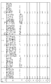
- FIG. 2 is a diagram illustrating templates of lines, corners, areas, and contact points described on a check sheet in FIG. 1. It is a conversion table of a template.
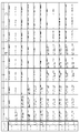
- FIG. 2B is a continuation of FIG. 2B. It is a code table which shows the meaning of each icon, and the display when each icon is placed in each line, each contact, each corner, and each area.
- FIG. 3B is a continuation of FIG. 3A.
- FIG. 3A is a continuation of FIG. 3A.
- FIG. 3C is a continuation of FIG. 3B.
- FIG. 3C is a continuation of FIG. 3C.
- FIG. 3D is a continuation of FIG. 3D.
- FIG. 3C is a continuation of FIG. 3E.
- FIG. 3C is a continuation of FIG. 3F.
- FIG. 3G is a continuation of FIG. 3G.
- FIG. 3C is a continuation of FIG. 3H.
- FIG. 3C is a continuation of FIG. 3I.
- FIG. 3C is a continuation of FIG. 3J.
- FIG. 3C is a continuation of FIG. 3K. It is a figure which shows the meaning of the "polymerization" of an icon.
- FIG. 4B is a continuation of FIG. 4A.
- FIG. 4B is a continuation of FIG. 4B.
- FIG. 4B is a continuation of FIG. 4B.
- FIG. 4C is a continuation of FIG. 4C. It is a code table (single) of a logic comment of a visual approach suitability inspection method by the present invention.
- FIG. 5B is a continuation of FIG. 5A.
- FIG. 5B is a continuation of FIG. 5B.
- It is a code table (polymerization) of the logic comment of the visual approach suitability inspection method by the present invention.
- It is a master sheet for inspection analysis of the visual approach suitability inspection method according to the present invention.
- FIG. 7B is a continuation of FIG. 7A.
- FIG. 7B is a continuation of FIG. 7B. It is a master sheet for the headquarters computer of the visual approach aptitude test method by this invention. It is a figure showing the calculation logic of "dense arrangement".
- FIG. 10 is a diagram illustrating calculation logic of “protruding arrangement”. It is a figure showing the calculation logic of “doll (DOLL) arrangement”. It is a figure which shows the reference
- FIG. 1 shows an embodiment of the visual aptitude suitability inspection method according to the present invention, showing a scanner input image of an icon attached to a check sheet by a subject, and (B) shows the location of the input data in (A) in a computer.
- FIG. (A) shows another embodiment of the visual approach suitability inspection method according to the present invention, showing a scanner input image of an icon affixed to a check sheet by a subject, and (B) shows the input data according to (A) in a computer.
- FIG. (A) shows another embodiment of the visual approach suitability inspection method according to the present invention, showing a scanner input image of an icon affixed to a check sheet by a subject, and (B) shows the input data according to (A) in a computer.
- FIG. (A) shows another embodiment of the visual approach suitability inspection method according to the present invention, showing a scanner input image of an icon affixed to a check sheet by a subject, and (B) shows the input data according to (A) in a computer.
- FIG. (A) shows another embodiment of the visual approach suitability inspection method according to the present invention, showing a scanner input image of an icon affixed to a check sheet by a subject, and (B) shows the input data according to (A) in a computer.
- FIG. 19B is a diagram showing templates of lines, corners, areas, and contact points written on the check sheet of FIG. 19A.
- FIG. 9 is a view showing still another embodiment of the check sheet used in the visual approach suitability inspection method according to the present invention.
- FIG. 9 is a view showing still another embodiment of the check sheet used in the visual approach suitability inspection method according to the present invention.
- FIG. 1 shows check sheets and icons used in the visual approach suitability inspection method according to the present invention.
- an area formed by combining boundary elements which will be described later, is drawn in an inspection area without a frame, which is a so-called open sheet.
- the area displayed on the screen is regarded as a window when the check sheet is considered as a part of the spherical body.
- this window is shown by a two-dot chain line in FIG.
- the check sheet is provided with areas composed of a large number of circle-like figures and polygon-like figures by appropriately combining lines consisting of straight lines, curves, and dashed lines, thereby providing closed spaces, open spaces, circular open spaces, and trapezoidal portions.
- the subject is provided with a paper check sheet shown in FIG. 1A and an icon sheet on which the icon shown in FIG. 1C is removably attached.
- the head office computer (not shown) stores the same graphic and area as the check sheet of FIG. 1A and the icon of FIG. 1C.
- the head office computer also stores the template of FIG. 2A and the conversion table of FIG. 2B.
- boundary elements shown in FIG. 1 will be outlined. A detailed explanation is given in the following paragraphs. Different types of boundary elements are drawn in the window 1 shown by two-dot chain lines for convenience.
- the boundary elements are a circular figure 5 having a notch 4 on the upper right side of the circumference of the curve 3 and a triangular figure 7 having a notch 6 at the apex, and hypotenuses 8 and 9 as opposing straight lines.
- FIG. 2A shows a template of lines, corners, areas and contacts described on a check sheet
- FIGS. 2B and 2C show conversion tables thereof.
- Table 1A shows lines L1 to L18.
- Table 1B shows corners C1 to C4.
- Table 1C shows areas A1 to A-13.
- Table 1D shows the contacts X1 to X8.
- Table 2 shows the shapes, names and colors of the icons.
- Tables 3A and 3B show the relationship between the icons and the meaning of the image for each system of A to H.
- Table 4 shows the definition of the meaning of the total number of selected icons.
- Table 5 shows a definition of a specific pattern (described later) grasped as a specific situation.
- Table 6 provides definitions for the interpretation of these specific patterns.
- Table 7 is a template indicating the meaning of the icon (described later).
- the head office computer stores in advance the information of FIGS. 1 to 11 (described later), FIGS. 18A to 18M, and Tables 1A to 8.
- Table 8 shows the relationship between Tables 1 to 6 and each table and each figure.
- the designated comments in Table 3A, Table 3B, Table 4, Table 5, and Table 6 are based on knowledge obtained from statistical processing of test result data.
- the subject selects and affixes the icon to the check sheet shown in FIG.
- the same icon as the icon shown in FIG. 1 is stored in a computer (not shown).
- the number of icons to be attached is limited, and is set to 10 or more and 15 or less.
- the reason is that, in the present invention, it is necessary to assume a large number of subjects rather than looking at the situation of each individual alone, and therefore, the number of pasted items is limited. Therefore, in the present invention, the icons are reduced in size to such an extent that no frustration occurs even at the lower limit.
- the icon when the icon is attached to the check sheet, the space occupancy becomes small and the degree of freedom of the attachment is lost. Therefore, the icon itself is reduced in order to secure the degree of freedom of the attachment. This is because the space recognition when affixed to the check sheet is expanded.
- the definitions of the lines, areas, corners and contacts described on the check sheet described above are stored in advance as a table 1, and the types of the icons described above and the meanings of the icons are described.
- the definition is stored as Table 2.
- the table 3 of the storage means has meanings as shown in FIGS. 3A to 3L depending on which position of the check sheet, that is, which line, each corner, each area and each contact has the icon.
- the defined definition and code number are stored.
- the table 4 of the storage means stores definitions and code numbers given as meanings as shown in FIGS. 4A to 4D by a relationship (icon relationship) between a plurality of icons or a positional relationship between icons and lines.
- FIGS. 5A to 5C are code tables (single) of the logic comment of Table 3 described above
- FIG. 6 is a code table (superimposed) of the logic comment of Table 3 described above
- 7A to 7C show a master sheet for inspection analysis
- FIG. 8 shows a master sheet for a head office computer.
- Table 5 of the storage means specific patterns defined as shown in Tables 5 and 7 are stored as specific situations. The ten specific patterns will be described later with reference to FIGS. 9A to 9G.
- Table 5 of the storage means also stores specific patterns defined for "superposition", “joining", “line joining” and “proximity” described later in Table 6.
- a type human type: face I want to relate to people. There are people who want to be targeted. I can't ignore people. There is an important person. There is a disgusting person.
- B system circle, ellipse Circle: Gentleness. Warmth. It was relaxed. I'm not nervous. Calm. Ellipse: gentle. good person. People (humans). Eggs, raw warm. I can feel safe.
- C system three-dimensional system: donut, cylinder, cube Donut: discomfort. There is a hole. I want to escape. I want to hide. Move. car. Run. Column: I want to be fulfilled.
- the “specific situations” shown in Table 5 define the following 10 types of specific patterns. It is described next.
- 9A to 9G are specifications for a specific situation of the table 5, FIG. 9A is a calculation logic of “dense arrangement”, FIG. 9B is a calculation logic of “distributed arrangement”, FIG. 9C is a calculation logic of “deviation arrangement”, 9D shows the calculation logic of the “bottom arrangement”, FIG. 9E shows the calculation logic of the “top arrangement”, FIG. 9F shows the calculation logic of the “outside arrangement”, and FIG. 9G shows the calculation logic of the “doll (DOLL) arrangement”.
- FIG. 9A is a calculation logic of “dense arrangement”
- FIG. 9B is a calculation logic of “distributed arrangement”
- FIG. 9C is a calculation logic of “deviation arrangement”
- 9D shows the calculation logic of the “bottom arrangement”
- FIG. 9E shows the calculation logic of the “top arrangement”
- FIG. 9F shows the calculation logic of the “outside arrangement”
- FIG. 9G shows the calculation logic of the “doll (DOLL) arrangement”.
- the definition and calculation logic of each specific situation are shown below.
- the dense arrangement means a case where the centers of gravity of all icons exist in two adjacent areas or three adjacent areas. For example, areas A2, A10, and A9.
- the calculation logic is as follows. (A) The area A4 is determined as a part of either the area A1 or the area A8. The area A5 is determined as a part of either the area A3 or the area A8. (A) When there is an icon that does not belong to the areas A1 to A13, it is not the “dense arrangement”. There are the following 58 combinations of adjacent areas.
- the distributed arrangement refers to a case where one or two icons exist in an area not close to the line. In this case, the areas A1, A2, and A3 are not targeted for the adjacent lines.
- the calculation logic is as follows. (A) If there are two or more icons in any of the areas A1, A2, A3, (B) When there is an icon that does not belong to A1 to A13, (C) If there are three or more icons in any of A4 to A13, it is not a distributed arrangement. (D) Also, ⁇ 1> when there is at least one icon belonging to the areas A6 and A7, ⁇ 2> when at least one icon belongs to the areas A6 and A8, and ⁇ 3> icons that belong to the areas A6 and A13.
- the balance arrangement means a case where only one icon at most exists in one area.
- the calculation logic is as follows. In the following cases, it is not "balanced arrangement". ⁇ 1> When there is an icon that does not belong to the areas A1 to A13, ⁇ 2> When there are two or more icons in one area, ⁇ 3> When there are icons equal to or less than the specified number, but not less than the specified number
- the deviation arrangement refers to a case where all icons exist in the two outermost areas. However, areas A4 and A5 are determined as area A8.
- the calculation logic is as follows. The following cases are deviation arrangements. (FIG. 9C) ⁇ 1> Icon exists in all areas A6 and A7 ⁇ 2> Icon exists in areas A6 and A13 ⁇ 3> Icon exists in areas A7 and A8 ⁇ 4> Icon exists in areas A8 and A9 ⁇ 5> Icon exists in all areas A9 and A10 ⁇ 6> Icon exists in all areas A10 and A11 ⁇ 7> Icon exists in all areas A11 and A12 ⁇ 8> Icon exists in areas A12 and A13 If all exist,
- the bottom side arrangement refers to a case where all the icons exist in the bottom side areas A11, A12, and A13. Therefore, there are the following seven combinations of the bottom side arrangement by this calculation logic (FIG. 9D). ⁇ 1> Area A11 ⁇ 2> Area A12 ⁇ 3> Area A13 ⁇ 4> Areas A11 and A12 ⁇ 5> Areas A11 and A13 ⁇ 6> Areas A12 and A13 ⁇ 7> Areas A11, A12 and A13
- the upper layout refers to a case where all the icons exist in the upper areas A7, A8, and A9. Therefore, there are the following seven combinations of the upper arrangement by the calculation logic (FIG. 9E). ⁇ 1> Area A7 ⁇ 2> Area A8 ⁇ 3> Area A9 ⁇ 4> Areas A7 and A8 ⁇ 5> Areas A7 and A9 ⁇ 6> Areas A8 and A9 ⁇ 7> Areas A7, A8 and A9
- the protruding arrangement refers to a case where all the icons are stepping on any one of the outer lines L-1 to L-7 or are protruding outside.
- the protruding arrangement calculation logic is determined based on the area and line information from the analysis engine, not on the position of the center of gravity of the icon. All icons have eight areas shown in FIG. 9F, that is, ⁇ 1> OUT U / L ⁇ 2> OUT U ⁇ 3> OUT U / R ⁇ 4> OUT R ⁇ 5> OUT D / R ⁇ 6> OUT D ⁇ 7> OUT D / L ⁇ 8> OUT L If the flag is ON (ON), it is determined to be "protruding arrangement".
- the vertical arrangement means that all icons exist in the upper areas A-7, A-8 and A-9 and the lower areas A-13, A-12 and A-11, and this is the calculation logic. .
- the left and right arrangement means that all icons are present in the left areas A-7, A-6 and A-13 and the right areas A-9, A-10 and A-11, and this is the calculation logic. .
- the doll (DOLL) arrangement refers to a case where an icon serving as a DOLL face exists in the areas A4 and A5.
- the calculation logic of the doll (DOLL) arrangement is as follows. First, icons that can be faces Face (icon number 11) Circle (icon number 1) Ellipse (icon number 5) Donut (icon number 13) Star (icon number 18).
- FIG. 10 shows a reference provided separately for determining the details of the DOLL arrangement. This is also stored in the storage means of the computer.
- Table 7 is a template showing the meaning of the icons input to the computer. Based on Table 7, the presence or absence of the icon sticker picked up by the subject and affixed to the check sheet is input. If the computer cannot judge the status of the attachment of the icon, the person in charge may perform the determination based on Table 7 in some cases.
- Dense arrangement When many icons are gathered in some area (contact / stacking) and pasted (see typical example in FIG. 18A)
- Distributed arrangement When icons are almost dispersedly attached (see a typical example in FIG. 18B)
- Balance arrangement When affixed to each area in a well-balanced manner (see a typical example in FIG. 18C)
- Deviation arrangement In the case where icons are pasted together so that there are clusters (see the typical example in FIG. 18D)
- Bottom arrangement When three or more icons are attached to the bottom (including the bottom) (see a typical example in FIG.
- Top arrangement When three or more icons are attached to the upper part (see a typical example in FIG. 18F) Top and bottom arrangement: icons are affixed to the top and bottom sides and there are no icons in the middle layer (other than top and bottom) (see typical example in FIG. 18G) Left and right arrangement: when icons are attached to the right and left sides and there are no icons in the middle (other than left and right) parts (see typical example in FIG. 18H) Protruding arrangement: the case where the icon is pasted out of the line of the outer frame and the case where the icon is stepped on the line of the outer frame are also included (see the typical example of FIG. 18I).
- DOLL arrangement a case where a face and a circular icon are pasted at a designated position (A4 / A5), and a case where they are pasted like a doll (head and torso) at other positions (see a typical example of FIG. 18J).
- Superposition When icons are pasted together (see the typical example in FIG. 18K)
- Joining When the icons are pasted in contact with each other at a line, surface, or point (see a typical example in FIG. 18L).
- Proximity When three or more icons are pasted so that they are likely to touch each other (see a typical example in FIG. 18M).
- 18A to 18M show typical examples described in the “sample” column of Table 7.
- one item is usually selected, but it is set so that up to two items may be selected. Thereby, the arrangement status can be grasped first. However, there is a combination that does not cause inconsistency even in the polymerization for those indicating the upper, lower, left, and right positions, so that the combination is set to be recognized.
- the mental structure of the subject is determined using the computer having the above configuration.
- the subject pastes a desired number of icons (10 or more and 15 or less) at desired positions on the check sheet within a time limit (about 5 minutes).
- the check sheet to which this icon is attached is computer-processed based on the flowchart of FIG. 12 through the steps from S1 to S16.
- the processing procedure by the computer will be described with reference to FIG. First, the check sheet with the icon attached is read into the head office computer (S1). Next, the total number of the pasted icons is counted (“count up” ⁇ S2).
- the determination of the specific situation is “dense arrangement” (S3), “distributed arrangement” (S4), “balanced arrangement” (S5), “deviation arrangement” (S6), “bottom arrangement” (S7), “top arrangement” ( S8) Whether or not it corresponds to all or a part of the “protruding arrangement” (S9), the “doll (DOLL) arrangement” (S10), the “vertical arrangement” (S11), and the “horizontal arrangement” (S12). It is a judgment.
- the series of “specific situation” (S3 to S12) determination steps is a step of extracting an icon pasting situation.
- Dense arrangement strong request. Strong commitment. Aggression. Deflection. Envy ashamedy. Dense power. I can't do it. Distributed arrangement: Scatter. Distraction. I can't break the shell. Unknown anxiety. I can't rely on it. Balance arrangement: equal consciousness, average consciousness. Sense of balance, relief of anxiety. Anxiety dispersion. Subdivision awareness. Deviation arrangement: distracted feeling. I like it. suitable. Consciousness deviation. Indecision. Bottom arrangement: stability-oriented. Dependence. Seeking peace of mind. have confidence. Strong awareness of the current situation. Do not transfer. Protruding arrangement: over-consciousness, sloppy. Hot flashes.
- the determination of the doll (DOLL) arrangement is made by the table 6 (FIG. 10) in which the definition of the formation of the face and the torso is stored. Regarding this determination, the person in charge manually corrects the processing result based on the above criteria as necessary.
- the evaluation by counting up which counts the total number of icons, is as follows. ⁇ 1> When the number of count-ups is not limited, the evaluation is performed as follows. 0: Equivalent to rejection of response and evaluated as no response or simple rejection (do not want to). 1 to 17: Evaluate motivation, self-expression, and self-assertion (many: high). 18 (ALL): Self-assertion (very high), high motivation, high interest. ⁇ 2> There is a case where the count-up number is limited (10 or more and 18 or less) 9 or less: Evaluate as misunderstanding, low response or simple rejection (do not want). 10 to 17 (designated): Evaluated as motivation, self-expression, self-assertion (many: high). 18 (ALL): Misunderstanding, self-assertion (very high), high motivation, high interest.
- the mental structure that is, the function of the mind, can be regarded as a response of the amygdala, and a response of the neocortex.
- the response of the amygdala precedes the response of the neocortex by about 100 ms.
- Amygdala reactions include likes and dislikes, perception of danger, disgust, discomfort, and the like.
- the amygdala emits a danger signal for foreign substances (including unknown substances) entering the body, and reflexes and the like are immediately performed without passing through the neocortex.
- neocortical responses are recognized as being affected by the experience and knowledge of specific individuals.
- the present invention is based on the recognition that in the analysis of the selected and arranged icons, some are determined only by the amygdala response and others are reached by the neocortical response.
- Polymerization indicates a state in which a plurality of icons are overlapped, and is regarded as a reaction of the amygdala.
- the icons that are selected and pasted are recognized as representatives of people and objects, and the superimposition reveals hidden consciousness and tendencies such as hiding and crushing.
- “Joining” indicates a state where the peripheral portions of the icons are in contact with each other, and is regarded as a reaction of the neocortex. Although this indicates a close relationship, it can be regarded as a reaction that cannot be taken until polymerization.
- Line joining indicates a state in which the line of the check sheet is in contact with the periphery of the icon, and is regarded as a reaction of the amygdala. This is a rare reaction that represents strangeness. The neocortical response can be considered as an unconscious response that does not work much.
- Proximity indicates a state in which the icon is in contact with another icon and the line component of the check sheet, and is a reaction of the neocortex.
- the only difference between the icons is that they can be moved, and the response of the amygdala precedes the response of the neocortex by 100 ms.
- the context of selective pasting will be affected. That is, The interaction between the icons means that the meaning of the existence of the icons alone is separated, and a relationship between the icons is generated. For example, the star icon and the moon icon are recognized as being located at the top from recognition as celestial bodies. The combination of the round and square icons reminds of a doll from its shape.
- Dense arrangement means that icons are concentrated on a specific area or point.
- the clustering includes a clustering clustering, a junction clustering, and a polymerizing clustering in stages, which indicates an introversion and includes a request to hide itself in a cluster. This reaction comes from likes and dislikes, and the amygdala reaction has priority.
- Balance arrangement is a case where the objects are arranged in a well-balanced manner, such as one by one in the area. This is a special state of distributed arrangement, a neocortical response. If there is no sense of balance in the neocortex, no balance arrangement is formed.
- the deviation arrangement is not as dense as the arrangement, and is a state in which the icons are slightly concentrated in an area.
- the deviation arrangement is a case where the distribution of the icons is biased, and the reaction of the amygdala has priority and influences.
- the neocortex has little effect as it requires subsequent correction.
- Bottom layout is when the icon is located at the bottom of the frame.
- the bottom placement is a response for stability, a response by the neocortex that lags behind the amygdala.
- Top arrangement is where icons are concentrated in the top three areas.
- the arrangement at the top retains a natural feeling, and the relationship with the icons is important.
- stars and moons are originally located in the upper sky and usually represent a sense. When a star or moon icon is placed at the bottom, it can be evaluated that there is some influence on the neocortex. When many icons are arranged at the top, this indicates anxiety. Anxiety is a response of the neocortex, and it can be seen that the influence of the later reaction is increasing.
- the icons are located in the upper and lower areas, and there are not many icons in the center and center.
- the vertical arrangement is expressed as a result of being influenced by likes and dislikes and a sense of discomfort. That is, the reaction of the amygdala is prioritized.
- the left and right arrangement is a case where the icon is located in the left and right areas, and is a logical reaction, and therefore a neocortical reaction.
- the frequency of vertical and horizontal reactions is low.
- the protruding layout is classified into complete protruding from the frame and partial protruding.
- Complete protrusion is a reaction in which the response of the amygdala is prioritized, and what was potentially present is interpreted as having responded to the presence of an expression field.
- Partial protrusion is a reaction in which the neocortical response is prioritized over the amygdala response, and a hesitant state can be regarded as this response.
- Doll arrangement is a case where the icons located below are squares and the icons located above are circulars.
- the doll configuration is a neocortical response, which is what the latent neocortical response originally manifested.
- the sensory system responds first before thinking, analyzing and judging by the neocortex. That is, the retina responds to the visual information and is transmitted to the amygdala. At this time, the brain also responds to the neocortex, producing a potential response.
- the pasting of icons may become tired of reaction over time, but if interest or motivation is high, the reaction will continue and the number of pasting will increase. Even when the number of count-ups is limited, the neocortex responds similarly within the range limits.
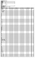
- FIG. 11 shows the contents of the processing specification table stored in the storage means, and the processing result is output as an inspection result as follows.
- Icon part Counter: Number of stickers
- Icon part specific situation
- Icon section Purposition status of icon pasting
- Icon section single and combined status of hiring icons
- the data processed by the computer is stored in the head office computer as the inspection result according to the present invention.
- FIG. 11 The arrangement order of the icons shown in FIG. 11 will be described.
- icons that are gradually rounded from the rounded icons are arranged in order from left to right.
- the setting of the icon number 12 (month), the icon number 18 (star), and the icon number 16 (heart figure) are separate, and the arrangement order is from left to right in the above order. .
- FIGS. 13 to 17 show examples by the subject.
- (A) shows an example of pasting of an icon by the subject
- (B) shows processing of data in a computer in which the locations of the pasted icons are totaled.
- the subject 0001 is determined at this stage as follows.
- the subject 0002 is determined at this stage as follows.
- the subject 0003 is determined at this stage as follows.
- the subject 0004 is determined at this stage as follows.
- the subject 0005 is determined at this stage as follows.
- the standard test time for providing an icon according to the present invention is about 5 minutes.
- there is an age limit for persons to be inspected and persons who have reached a workable age and who are up to 60 years old can be examined, and are particularly suitable for persons up to about 45 years old.
- the present invention is not limited to the above embodiment.
- the figure shape in which the area is defined is not limited to the shape as shown in FIG. 1, and various shapes are conceivable.
- the shape may be defined by the figure as shown in FIGS. 19A and 20.
- the boundary elements drawn in the rectangular window 1 composed of the virtual window lines 1a to 1d are a circular figure 5 having a notch 4 at the upper part of the circumference as the curve 3, and a notch 6 at the vertex.
- a figure having an intermediate side 11 as a straight line parallel to a base 10 as a straight line between hypotenuses 8 and 9 as opposing straight lines, and a window virtual from the right end of the intermediate side 11 A straight line (inclined straight line) 13 inclined downward to the right to the line 1b, a broken line (inclined broken line) 14 inclined upward from the middle of the inclined straight line 13 to the lower part of the circular figure 5, and an intermediate portion of the base 10 , And an S-shaped curve 15 rising to the window virtual line 1d.
- the above-described area is divided into three sections in the horizontal direction and the vertical direction into a total of nine sections.
- the notch 4 is formed upward, and the notch 6 is formed downward.
- the boundary elements drawn in the rectangular window 1 composed of the virtual window 1a to the virtual window 1d are a circular figure 5 having a notch 4 at the upper right side of the circumference as the curve 3, and a vertex A figure having a notch 6, a figure 7 having a middle side 11 as a straight line parallel to a base 10 as a straight line between oblique sides 8 and 9 as opposite straight lines, A straight line (inclined straight line) 13 inclined upward to the right from the right end to the virtual window line 1a, and a broken line (inclined broken line) 14 inclined upward to the left from the end of the base 10 on the side opposite to the inclined straight line 13 from the left end to the virtual window line 1c.
- FIG. 21 shows a case where a part of the above-described boundary elements is used.
- the boundary element is made up of orthogonal straight lines 18a and 18b in the window 1, and a rectangular hole 20 having an open upper part 19 is arranged on the left side in parallel with straight lines 21a and 21b and the straight lines 21a and 21b.
- a U-shaped hole 24 having a semicircular curve 22 connecting the lower ends of 21a and 21b and having an open upper portion 23 is disposed on the right side.
- the visual approach aptitude test method according to the present invention can be used to judge the suitability of human resources according to the type of job, such as a company or government office entrance examination (including mid-career recruitment examination) and a promotion examination. Can be used for appraisal.
Landscapes
- Engineering & Computer Science (AREA)
- Health & Medical Sciences (AREA)
- Business, Economics & Management (AREA)
- Physics & Mathematics (AREA)
- General Physics & Mathematics (AREA)
- Theoretical Computer Science (AREA)
- Life Sciences & Earth Sciences (AREA)
- Educational Technology (AREA)
- Medical Informatics (AREA)
- Public Health (AREA)
- Biomedical Technology (AREA)
- Educational Administration (AREA)
- General Health & Medical Sciences (AREA)
- Pathology (AREA)
- Human Resources & Organizations (AREA)
- Entrepreneurship & Innovation (AREA)
- Psychiatry (AREA)
- Psychology (AREA)
- Data Mining & Analysis (AREA)
- Strategic Management (AREA)
- Hospice & Palliative Care (AREA)
- Heart & Thoracic Surgery (AREA)
- Molecular Biology (AREA)
- Surgery (AREA)
- Animal Behavior & Ethology (AREA)
- Veterinary Medicine (AREA)
- Biophysics (AREA)
- Social Psychology (AREA)
- Developmental Disabilities (AREA)
- Child & Adolescent Psychology (AREA)
- Primary Health Care (AREA)
- Epidemiology (AREA)
- Databases & Information Systems (AREA)
- Marketing (AREA)
- Operations Research (AREA)
- Quality & Reliability (AREA)
- Tourism & Hospitality (AREA)
- General Business, Economics & Management (AREA)
- Economics (AREA)
- Measurement Of The Respiration, Hearing Ability, Form, And Blood Characteristics Of Living Organisms (AREA)
Priority Applications (4)
| Application Number | Priority Date | Filing Date | Title |
|---|---|---|---|
| EP19825073.0A EP3816898A4 (en) | 2018-06-27 | 2019-06-21 | VISUAL APPROACH BASED PROFIT TESTING PROCEDURE |
| KR1020217000489A KR102640583B1 (ko) | 2018-06-27 | 2019-06-21 | 시각 어프로치 적성 검사 방법 |
| CN201980042519.7A CN112567404A (zh) | 2018-06-27 | 2019-06-21 | 视觉方法才能检验方法 |
| US17/133,182 US20210118319A1 (en) | 2018-06-27 | 2020-12-23 | Visual approach-based aptitude testing method |
Applications Claiming Priority (2)
| Application Number | Priority Date | Filing Date | Title |
|---|---|---|---|
| JP2018-121575 | 2018-06-27 | ||
| JP2018121575A JP6895411B2 (ja) | 2018-06-27 | 2018-06-27 | 視覚アプローチ適性検査方法 |
Related Child Applications (1)
| Application Number | Title | Priority Date | Filing Date |
|---|---|---|---|
| US17/133,182 Continuation US20210118319A1 (en) | 2018-06-27 | 2020-12-23 | Visual approach-based aptitude testing method |
Publications (2)
| Publication Number | Publication Date |
|---|---|
| WO2020004268A1 true WO2020004268A1 (ja) | 2020-01-02 |
| WO2020004268A9 WO2020004268A9 (ja) | 2020-07-30 |
Family
ID=68986837
Family Applications (1)
| Application Number | Title | Priority Date | Filing Date |
|---|---|---|---|
| PCT/JP2019/024723 Ceased WO2020004268A1 (ja) | 2018-06-27 | 2019-06-21 | 視覚アプローチ適性検査方法 |
Country Status (6)
| Country | Link |
|---|---|
| US (1) | US20210118319A1 (https=) |
| EP (1) | EP3816898A4 (https=) |
| JP (1) | JP6895411B2 (https=) |
| KR (1) | KR102640583B1 (https=) |
| CN (1) | CN112567404A (https=) |
| WO (1) | WO2020004268A1 (https=) |
Citations (2)
| Publication number | Priority date | Publication date | Assignee | Title |
|---|---|---|---|---|
| JPH11285483A (ja) * | 1998-04-02 | 1999-10-19 | Aesop:Kk | 心理状態分析装置 |
| KR20150145844A (ko) * | 2014-06-19 | 2015-12-31 | 주식회사 티앤티인재개발원 | 도형 및 문항 검사를 통한 온라인 심리분석 서비스 방법 |
Family Cites Families (8)
| Publication number | Priority date | Publication date | Assignee | Title |
|---|---|---|---|---|
| US4058911A (en) * | 1976-08-18 | 1977-11-22 | The United States Of America As Represented By The Secretary Of The Department Of Transportation | Road-runner alcohol safety interlock system |
| US5973692A (en) * | 1997-03-10 | 1999-10-26 | Knowlton; Kenneth Charles | System for the capture and indexing of graphical representations of files, information sources and the like |
| BRPI0511299A (pt) * | 2004-05-21 | 2007-12-04 | Pressco Tech Inc | interface de preparação de usuário para re-inspeção gráfica |
| KR20110055215A (ko) * | 2009-11-19 | 2011-05-25 | 정효경 | 다중지능을 이용한 적성 검사 방법 및 이를 이용한 온라인 직업 적성 검사 방법 및 시스템 |
| JP5033217B2 (ja) * | 2010-04-26 | 2012-09-26 | 株式会社夢のみずうみ社 | 生涯学習支援システム |
| US20140066802A1 (en) * | 2012-08-31 | 2014-03-06 | Greatbatch Ltd. | Cognition and Usability Aptitude Evaluations for Clinician Programmers |
| TWI590143B (zh) * | 2013-03-26 | 2017-07-01 | Mitac Int Corp | Graphical questionnaire production method and questionnaire method |
| KR101860026B1 (ko) * | 2017-07-06 | 2018-05-21 | 주식회사 로로아트플랜 | 멀티 미로영역 상의 사용자 이동정보를 이용한 심리적성검사 시스템 |
-
2018
- 2018-06-27 JP JP2018121575A patent/JP6895411B2/ja active Active
-
2019
- 2019-06-21 WO PCT/JP2019/024723 patent/WO2020004268A1/ja not_active Ceased
- 2019-06-21 EP EP19825073.0A patent/EP3816898A4/en active Pending
- 2019-06-21 CN CN201980042519.7A patent/CN112567404A/zh active Pending
- 2019-06-21 KR KR1020217000489A patent/KR102640583B1/ko active Active
-
2020
- 2020-12-23 US US17/133,182 patent/US20210118319A1/en not_active Abandoned
Patent Citations (2)
| Publication number | Priority date | Publication date | Assignee | Title |
|---|---|---|---|---|
| JPH11285483A (ja) * | 1998-04-02 | 1999-10-19 | Aesop:Kk | 心理状態分析装置 |
| KR20150145844A (ko) * | 2014-06-19 | 2015-12-31 | 주식회사 티앤티인재개발원 | 도형 및 문항 검사를 통한 온라인 심리분석 서비스 방법 |
Non-Patent Citations (9)
| Title |
|---|
| "Phonology", vol. I, BASIL BLACKWALL, article "A Grammar of Old English" |
| ANONYMOUS: "Applicability inspection for web application test (TAL)", KONPAN, 7 March 2010 (2010-03-07), pages 1 - 9, XP055667963, Retrieved from the Internet <URL:http://konpan.com/panlog/20100307/web-test-tal> [retrieved on 20190722] * |
| ANONYMOUS: "Marky WEB", WEB PROPER INSPECTION (TAL), 11 August 2012 (2012-08-11), pages 1 - 5, XP055667953, Retrieved from the Internet <URL:https://ameblo.jp/secom-desu/entry-11288062986.html> [retrieved on 20190722] * |
| JOHANNA PAULAMONIQUE FIKKERTHAIKE JACOBS, LANGUAGE ARTS & DISCIPLINES, 2003, pages 463 |
| KARASEKTHEORELL, PSYCHOLOGICAL DEMAND/DECISION LATITUDE MODEL, 1990 |
| LAZARUS, RSFOLKMAN, S: "Stress, Appraisal, and Coping", 1984, SPRINGER |
| METRICAL STRESS THEORY: PRINCIPLES AND CASE STUDIES, 1995 |
| ROBERT T. KELLER, THE ACADEMY OF MANAGEMENT JOURNAL, vol. 44, no. 3, June 2001 (2001-06-01), pages 547 - 555 |
| See also references of EP3816898A4 |
Also Published As
| Publication number | Publication date |
|---|---|
| WO2020004268A9 (ja) | 2020-07-30 |
| EP3816898A1 (en) | 2021-05-05 |
| US20210118319A1 (en) | 2021-04-22 |
| EP3816898A4 (en) | 2022-03-16 |
| JP2020003982A (ja) | 2020-01-09 |
| KR102640583B1 (ko) | 2024-02-27 |
| JP6895411B2 (ja) | 2021-06-30 |
| KR20210025043A (ko) | 2021-03-08 |
| CN112567404A (zh) | 2021-03-26 |
Similar Documents
| Publication | Publication Date | Title |
|---|---|---|
| WO2020004265A1 (ja) | 視覚アプローチ適性検査システム | |
| WO2020004268A1 (ja) | 視覚アプローチ適性検査方法 | |
| WO2020004267A1 (ja) | 視覚アプローチ適性検査方法 | |
| WO2020004266A1 (ja) | 視覚アプローチ適性検査方法 | |
| WO2020004263A1 (ja) | 視覚アプローチ適性検査システム | |
| WO2020004264A1 (ja) | 視覚アプローチ適性検査システム | |
| WO2020004262A1 (ja) | 視覚アプローチ適性検査システム | |
| WO2020004261A1 (ja) | 視覚アプローチ適性検査システム | |
| HK40048899A (zh) | 视觉方法才能检验方法 | |
| HK40048465A (en) | Visual approach-based aptitude testing system | |
| HK40049459A (en) | Visual approach-based aptitude testing system | |
| HK40048466A (en) | Visual approach-based aptitude testing system | |
| HK40049458A (en) | Visual approach-based aptitude testing method | |
| HK40048890A (en) | Visual approach–based aptitude testing system |
Legal Events
| Date | Code | Title | Description |
|---|---|---|---|
| 121 | Ep: the epo has been informed by wipo that ep was designated in this application |
Ref document number: 19825073 Country of ref document: EP Kind code of ref document: A1 |
|
| NENP | Non-entry into the national phase |
Ref country code: DE |
|
| ENP | Entry into the national phase |
Ref document number: 20217000489 Country of ref document: KR Kind code of ref document: A |
|
| ENP | Entry into the national phase |
Ref document number: 2019825073 Country of ref document: EP Effective date: 20210127 |